Performance Pipe, a Division of Chevron Phillips Chemical Company LP 5085 W. Park Blvd Suite 500 Plano, TX Phone: Fax:
|
|
|
- Brett Bates
- 6 years ago
- Views:
Transcription


1 Manual PP-750 December 2012 December 2012 supersedes all previous editions
2 PERFORMANCE PIPE HEAT FUSION JOINING PROCEDURES INTRODUCTION Performance Pipe, a Division of Chevron Phillips Chemical Company LP, is the functional successor to the operations of Plexco and Driscopipe PE piping. As a result, some Performance Pipe products may have the markings of the Plexco, Driscopipe or DriscoPlex PE piping brands. This Manual describes procedures and guidelines for joining Performance Pipe products using butt fusion, saddle fusion and socket fusion joining techniques. All procedures and guidelines in this document are in alignment with ASTM F2620 Standard Practice for Heat Fusion Joining of Polyethylene Pipe and Fittings QUALIFICATION OF PROCEDURE When used to join Performance Pipe polyethylene gas distribution pipe and fittings, Performance Pipe fusion joining procedures are qualified in accordance with U.S. Department of Transportation Regulation 49 CFR, Part 192, (b). GAS DISTRIBUTION PRODUCTS DriscoPlex 6500 PE Piping Driscopipe 6800 Piping Plexco Plexstripe II PE 3408 Mining Pipe Driscopipe 6500 PE Piping Driscopipe 8100 PE Piping Plexco Yellowstripe PE 3408 Piping DriscoPlex 6800 Piping Plexco Yellow Pipe PE 2406 Piping YELLOWSTRIPE 8300 PE Piping All Gas Distribution products listed above are compatible with these procedures. Do not join Driscopipe 7000 or 8000 PE Piping using these procedures. WATER, SPECIALTY, MUNICIPAL AND INDUSTRIAL PRODUCTS DriscoPlex 1000 PE Piping DriscoPlex 4000 PE Piping DriscoPlex 5300 PE Piping DriscoPlex 1100 PE Piping DriscoPlex 4100 PE Piping DriscoPlex 6300 PE Piping DriscoPlex 1700 PE Piping DriscoPlex 4600 PE Piping DriscoPlex 6400 PE Piping PlatinumStripe 1800 PE-RT Piping DriscoPlex 4700 PE Piping DriscoPlex 9200 PE Piping DriscoPlex 3100 PE Piping DriscoPlex 4800 PE Piping All Water, Specialty, Municipal and Industrial products listed above are compatible with these procedures. Do not join Driscopipe 7600 or 8600 PE Piping using these procedures. Manual PP-750 September 2017 Page 1 of 29 September 2017 supersedes all previous editions
3 OVERVIEW In heat fusion joining, mating surfaces are prepared and simultaneously melted with a hot-plate heater. The heater is then removed and the melted surfaces are pressed together and held under pressure. As the molten materials cool, they mix and fuse into a permanent, monolithic joint. Heat fusion procedures require specific tools and equipment based on the fusion type and the sizes of pipe and fittings being joined. Butt fusion is used to make end-to-end joints between butt or plain-end pipes and fittings that have the same outside diameter and like wall thickness. Like wall thickness means that the pipe or fitting ends being butt fused do not exceed one SDR difference (e.g. SDR 9.0 to SDR 11.0). Per ASTM, standard dimension ratio (SDR) is when the outside diameter divided by the minimum wall thickness equals one of the following values: 6.0, 7.3, 9.0, 11.0, 13.5, 17.0, 21.0, 26.0, 32.5 or Saddle (sidewall) fusion is used to install a branch outlet fitting to the top or side of a pipe main. Tapping tee fittings are usually installed on top of the pipe main, while branch or service saddle fittings are installed on the side of the main. After the fusion area has cooled, the main pipe wall is pierced (tapped) to enable flow through the branch. Hot tapping is saddle fusion to a live or pressurized main. Socket fusion is used to join 4 IPS and smaller tubing and pipe to socket fittings. Socket fittings are available for certain Performance Pipe PE materials. CAUTION Performance Pipe polyethylene piping products cannot be joined with adhesives or solvent cement. Joining by hot air (hot gas) welding or extrusion welding techniques and joining by pipe threading are not recommended for pressure service. PRECAUTIONS STATIC ELECTRICITY Polyethylene plastic pipe does not readily conduct electricity. A static electricity charge can build up on inside and outside surfaces and stay on the pipe surface until some grounding device such as a tool or a person comes close enough for the static electricity to discharge to the grounding device. Discharging one part of the pipe surface will not affect other charged areas because static electricity does not flow readily from one area to another. Polyethylene pipe cannot be discharged by attaching grounding wires to the pipe. WARNING Fire or Explosion Static electricity discharge can ignite a flammable gas or combustible dust atmosphere. A static electricity discharge to a person, a tool or a grounded object close to the pipe surface can cause an electric shock or a spark. That can then ignite a flammable gas or combustible dust atmosphere causing fire or explosion. Manual PP-750 September 2017 Page 2 of 29 September 2017 supersedes all previous editions
4 In gas utility applications, static electricity can be a potential safety hazard. Where a flammable gas-air mixture may be encountered and static charges may be present, such as when repairing a leak, squeezing-off an open pipe, purging, making a connection, etc., arc preventing safety precautions are necessary. 1 Observe all Company (pipeline operator, utility, contractor, etc.) procedures for static electricity safety and control, including procedures for discharging static electricity and requirements for personal protection. Take steps to discharge static electricity from the surface of a polyethylene gas pipe. Such steps include wetting the entire exposed pipe surface with a conductive anti-static liquid or a dilute soap and water solution, then covering or wrapping the entire wetted, exposed pipe surface with grounded wet burlap, conductive poly film or wet tape conductor. The external covering should be kept wet by occasional re-wetting with anti-static solution. The covering or tape should be suitably grounded such as to a metal pin driven into the ground. Steps that discharge the outer surface do not discharge the inner surface of the pipe. Squeeze-off, purging, venting, cutting, etc., can still result in a static electricity discharge. When appropriate, ground tools and remove all potential sources of ignition. Appropriate safety equipment should be used. Do not use polyethylene pipe for handling dry grain or coal where a static electricity discharge may ignite a combustible dust atmosphere and cause an explosion or fire. Polyethylene pipe is not recommended for pneumatic slurry applications. ELECTRIC TOOLS WARNING Fire or Explosion Electric tools or fusion equipment may not be explosionproof and may ignite a flammable gas or flammable dust atmosphere. DO NOT operate electrical devices that are not explosion proof in a flammable gas or flammable dust atmosphere. When a flammable gas-air mixture may be present, observe all gas system operator (pipeline or utility company and contractor) safety procedures for the use of electric tools and equipment. LIQUID HYDROCARBON PERMEATION When present, liquid hydrocarbons may permeate (solvate) polyethylene pipe. Liquid hydrocarbon permeation may occur when: 1) liquid hydrocarbons are present in the pipe; 2) where soil surrounding the pipe is contaminated with liquid hydrocarbons; or 3) where liquid hydrocarbon condensates can form in gas pipelines. Heat fusion joining to liquid hydrocarbon permeated pipes may result in a low strength joint. 1 See the AGA Plastic Pipe Manual For Gas Service 2000, American Gas Association, 1515 Wilson Boulevard, Arlington, VA Manual PP-750 September 2017 Page 3 of 29 September 2017 supersedes all previous editions
5 CAUTION Once polyethylene pipe has been permeated with liquid hydrocarbons, heat fusion or electrofusion joining is not recommended because liquid hydrocarbons will leach out during heating and contaminate the joint. Liquid hydrocarbon permeated polyethylene pipe should be joined using suitable mechanical connection methods. Contact the mechanical joining product manufacturer for connection and installation procedures. Liquid hydrocarbon contamination is indicated by a rough, sandpaper-like, bubbly or pockmarked surface when a fusion heating iron is removed from the pipe surface, and may be indicated by discoloration or by a hydrocarbon fuel odor. See the PPI Handbook of Polyethylene Pipe for additional information on permeation and chemical resistance. LEAKAGE AT FUSION JOINTS WARNING Correctly made fusion joints do not leak. When pressurized, leakage at a faulty fusion joint may immediately precede catastrophic separation and result in violent and dangerous movement of piping or parts and the release of pipeline contents under pressure. Never approach or attempt to repair or stop leaks while the pipeline is pressurized. Always depressurize the pipeline before making corrections. Faulty fusion joints must be cut out and redone. HANDLING Polyethylene piping is a tough, robust material, but it is not immune to damage. Improper handling or abuse can damage piping, compromise system performance and result in injury or property damage. Polyethylene piping should be unloaded and moved with proper handling and lifting equipment. Use fabric slings. Do not use chains or wire ropes. Do not roll or drop pipe off the truck or drag piping over sharp rocks or other abrasive objects. Store piping so that the possibility of mechanical damage is minimized. Visit for additional information on handling and storage. FUSION IN COLD WEATHER In cold weather, polyethylene becomes more sensitive to impact and is less flexible. Use additional care in handling. When temperatures are cold, avoid sharp impact such as dropping the pipe from moderate heights. Cold pipes will be harder to bend or uncoil. Butt, Saddle, or Socket Fusion is generally not recommended below -4 F (-20 C) without special provisions such as a portable shelter or trailer or other suitable protective measures with auxiliary heating. In inclement weather and especially in windy conditions, the fusion operation should be shielded to avoid precipitation or blowing snow and excessive heat loss from wind chill. Remove all frost, ice or snow from the OD and ID surfaces of areas to be fused. Surfaces must be clean and dry before fusing. Maintain the specified heating tool surface temperature. Do not increase heating tool surface temperature. Do not apply pressure during zero pressure butt or saddle fusion heating steps. Manual PP-750 September 2017 Page 4 of 29 September 2017 supersedes all previous editions
6 Do not increase butt or saddle fusion joining pressure. When making a butt fusion joint with the ambient temperature below 3 F(-16 C), pre-heat the pipe ends using a heating blanket or warm air device to elevate the pipe temperature to improve the heating starting condition. o With pipe mounted in the fusion machine, an alternate method of pre-heating is to stop the pipe ends within inches ( mm) of the heater plate face to allow the pipe ends to warm for 30 seconds to 2 minutes, depending on the pipe size and wall thickness. CAUTION - The use of direct application open flame devices, such as torches, for heating polyethylene pipe is prohibited due to the lack of adequate heating control and possibility of damage to the pipe ends. When fusing coiled pipe when the ambient temperature is below 32 F (0 C), it may be required to remove an end section of pipe from the coil and butt fuse on a straight section of pipe to enable correct pipe alignment. Completed joints shall be allowed to cool to ambient temperature before any stress is applied. When fusing in cold weather, the time required to obtain the proper melt may increase. In butt fusion, melt bead size determines heating time. As a result, the procedure automatically compensates when cold pipe requires longer time to form the proper melt bead size. For saddle fusion, establish the necessary cold weather heating time by making trial melt patterns in the field on non-pressurized, excess pipe that is at field temperature. Use the standard heating time, plus additional heating time in 3-second increments during bead-up, until the proper melt pattern is established on the pipe. A clean wood board or heat shield ( flyswatter ) should be used between the saddle fitting and the heater to avoid heating the fitting when making trial melt patterns. In socket fusion, it will be more difficult to fit a cold socket fitting into the heating tool socket face because polyethylene pipe and fittings will contract slightly in the cold. One way to compensate is to warm the socket fitting in the cab of the service truck before use. For the pipe, establish the necessary heating time by making trial patterns on excess pipe that is at field temperature. Use the recommended heating time, plus additional heating time in 3-second increments, until the proper melt pattern is established. Additional information on fusion in cold weather can be found in Annex 1 of ASTM F2620 Standard Practice for Heat Fusion Joining of Polyethylene Pipe and Fittings. KEY FACTORS FOR QUALITY FUSIONS Quality fusion requires using all of the required tools and equipment, and following all of the steps in the procedure in the correct sequence. Faulty fusion is caused by improper or defective equipment, omitting steps or doing things out of sequence. Training and experience provide knowledge and proficiency in what to do, what to expect and recognizing potential problems in advance. Inadequately trained or inexperienced persons can produce poor quality fusions and may expose themselves or others to hazards. Federal safety regulations require Manual PP-750 September 2017 Page 5 of 29 September 2017 supersedes all previous editions
7 that persons making joints in gas systems must be qualified in the pipeline operator s qualified fusion procedures (CFR 49, Part 192). The key factors below are necessary for quality fusion: Fusion tools and equipment must be correct for the job and in proper working order. Each fusion procedure requires specific tools and equipment to do the job properly. Incorrect or poorly maintained or damaged fusion tools or equipment or using the wrong tools or equipment can cause a poor fusion and may be hazardous. Use only the correct tools and equipment for the job. Do not use defective or improper tools or equipment. Follow the equipment manufacturer s procedures for equipment maintenance. The fusion operator must be proficient in tool and equipment use and operation, and proficient in fusion procedure. The operator should be thoroughly familiar with the tools and equipment and their use and operation. Improper use or an incorrect operating sequence can cause a poor fusion and may be hazardous. Know how to use the equipment and observe the manufacturer s instructions. Pipe and fitting surfaces must be clean and properly prepared. Dirty, contaminated or poorly prepared surfaces that do not mate together properly cannot produce a quality fusion. Clean and prepare the surfaces before joining. If contamination is reintroduced, clean the surfaces again. Heating tool surfaces must be clean, undamaged and at the correct surface temperature. Heating tool faces have non-stick coatings for quick, complete release from melted polyethylene. Dirty or contaminated heating tool faces can cause poor fusion and damaged coatings may not release properly from the melt. Use only wooden implements and clean, dry, lint-free, non-synthetic (cotton) cloths, or paper towels, to clean heating tool faces. Never use spray chemicals or metal tools on heating tool faces. Heating tool temperatures are specified for each procedure. (Butt fusion and saddle fusion heating tool temperatures are different.) The specified temperature is the temperature on the surfaces that contact the pipe or fitting being joined, not the heating tool thermometer temperature. Use a pyrometer or infrared thermometer to check for uniform temperature across both of the component contact surfaces. (Temperature indication crayons are not preferred. If used, temperature-indicating crayons must never be applied to a surface that contacts a pipe or fitting.) Uneven temperature may indicate a faulty heater. The heater thermometer measures the internal temperature, which is usually higher than surface temperature; however, heating tool temperature can be verified by checking the thermometer to ensure that the heating tool is maintaining temperature. When checking surface temperature with a pyrometer or infrared thermometer, note the heating tool thermometer reading. Check the heating tool thermometer reading before each fusion to verify that the heating tool is maintaining temperature properly. Incorrect or non-uniform temperature can cause poor fusion; low heating tool temperature can lead to a blowout during hot tap saddle fusion. Manual PP-750 September 2017 Page 6 of 29 September 2017 supersedes all previous editions
8 BEFORE YOU START: Inspect pipe lengths and fittings for unacceptable cuts, gouges, deep scratches or other deleterious defects. Damaged products should not be used. Remove surface damage at pipe ends that could compromise the joining surfaces or interfere with fusion tools or equipment. Be sure all required tools and equipment are on site, in proper working order and fueled up. The pipe and fitting surfaces where tools and equipment are fitted must be clean and dry to facilitate proper fusion and avoid contaminating fusion machine parts. Guidance on proper cleaning of PE pipe before fusion is given in ASTM F2620 Appendix X1. Use clean, dry, lint-free, non-synthetic (cotton) cloths, or paper towels, to remove dirt, snow, water and other contamination. Before installing the pipe in the fusion machine, 90% or greater isopropyl alcohol may be used to to remove bar oil from cut pipe ends or clean extremely dirty pipe before facing.the use of alcohol after facing the pipe ends is not recommended since a properly faced surface should be pure. If isopropyl alcohol is used to clean the pipe, it must be rinsed clean with water and dried thoroughly with clean, dry, lint-free, non-synthetic (cotton) cloths on the pipe ends, ID, and OD. Shield heated fusion equipment and surfaces from inclement weather and winds. A temporary shelter over fusion equipment and the fusion operation may be required. Relieve tension in the line before making connections. When joining coiled pipe, making an s-curve between pipe coils can relieve tension. In some cases, it may be necessary to allow pipe to equalize to the temperature of its surroundings. Allow pulled-in pipes to relax for several hours to recover from tensile stresses. Pipes must be correctly aligned before making connections. WARNING Impact Hazard Do not bend pipe into alignment against open butt fusion clamps. The pipe may spring out and cause injury or damage. Pipe must be aligned before placing it into butt fusion equipment. BUTT FUSION SET-UP PARAMETERS HEATING TOOL SURFACE TEMPERATURE - MINIMUM 400 F MAXIMUM 450 F ( C) Heating tool surfaces must be clean and up to temperature before beginning the fusion procedure. All points on both heating tool surfaces where the heating tool surfaces will contact the pipe or fitting ends must be within the prescribed minimum and maximum temperatures. GAUGE PRESSURE Gauge pressure is the pressure required for fusion. For hydraulic machines, the gauge pressure is a function of interfacial pressure, fusion surface area, machine s carriage cylinder size and drag pressure. Manual PP-750 September 2017 Page 7 of 29 September 2017 supersedes all previous editions
9 When calculated, gauge pressure is what the operator will input into the fusion machine. The total effective piston area can be obtained from the machine manufacturer. The drag pressure is the pressure that is required to overcome movement in the carriage. Interfacial pressure and gauge pressure are not the same. Manually operated machines do not require a calculation for gauge pressure. Below is the equation used to calculate for Gauge Pressure in psi. A slide rule or a gauge pressure calculator obtained from the machine s manufacturer can be a substitute for this calculation. PROCEDURE 1. Secure. Clean the inside and outside of the component (pipe or fitting) ends by wiping with a clean, dry, lint-free, non-synthetic (cotton) cloth, or paper towel. Remove all foreign matter. Align the components with the machine, place them in the clamps and then close the clamps. Do not force pipes into alignment against open fusion machine clamps. (When working with coiled pipe, if possible S the pipes on each side of the machine to compensate for coil curvature and make it easier to join.) Component ends should protrude past the clamps enough so that facing will be complete. Bring the ends together and check high-low alignment. Adjust alignment as necessary by tightening the high side down. 2. Face. Place the facing tool between the component ends and face them to establish smooth, clean, parallel mating surfaces. Complete facing produces continuous circumferential shavings from both ends. Face until there is a minimal distance between the fixed and moveable clamps. Some machines have facing stops. If stops are present, face down to the stops. Remove the facing tool and clear all shavings and pipe chips from the component ends. Do not touch the component ends with your hands after facing. 3. Align. Bring the component ends together, check alignment and check for slippage against fusion pressure. Look for complete contact all around both ends with no detectable gaps and outside diameters in high-low alignment. The maximum high-low misalignment is to be less than 10% of the pipe minimum wall thickness. If necessary, adjust the high side by tightening the high side clamp. Do not loosen the low side clamp because components may slip during fusion. Re-face if high-low alignment is adjusted. 4. Melt. Verify that the heating tool is maintaining the correct temperature. Place the heating tool between the component ends and move the ends against the heating tool. The initial contact should be under moderate pressure to ensure full contact then reduce to contact pressure only. On larger sizes (14 and larger), hold fusion pressure until an indication of melt is observed around the pipe ends before reducing pressure. PG OD DR IFP PD = Gauge Pressure, psi = Outside Diameter, in. = Dimension Ratio = Interfacial Pressure, psi ( bar) = Drag Pressure, psi TEPA = Total Effective Piston Area, in 2 Manual PP-750 September 2017 Page 8 of 29 September 2017 supersedes all previous editions
10 Hold the ends against the heating tool without force. Beads of melted polyethylene will form against the heating tool at the component ends. Use Table 1 to determine the minimum melt bead size from the pipe OD. When the proper melt bead size is formed, quickly separate the ends and remove the heating tool. This process should be completed within the recommended time in Table 2. Table 1: Minimum Melt Bead Size Pipe OD, in. (mm) Minimum Melt Bead Size, in. (mm) < 2.37 (60) 1/32 (1) 2.37 (60) 3.5 (89) 1/16 (1.5) > 3.5 (89) 8.62 (219) 3/16 (5) > 8.62 (219) to (324) 1/4 (6) > (324) to 24 (610) 3/8 (10) > 24 (610) to 36 (900) 7/16 (11) > 36 (900) to 65 (1625) 9/16 (14) Table 2: Maximum Heater Plate Removal Times Field Applications Pipe Wall Thickness, in. (mm) Common Gas Pipe OD Sizes Maximum Heater Plate Removal Time (Seconds) 0.17 to 0.36 (5 to 9) 2 DR 11.0; 3 DR 11.5; 3 DR > 0.36 to 0.55 (9 to 14) 4 DR 11.0; 4 DR 11.5; 6 DR > 0.55 to 1.18 (14 to 30) 6 DR 11.0 & 11.5; 8, 10, 12 DR 11.0; 11.5; > 1.18 to 2.5 (30 to 64) 20 > 2.5 to 4.5 (64 to 114) 25 To calculate for Wall Thickness, divide Actual Pipe OD by DR. Wall thickness values are also given in Performance Pipe Size and Dimension Charts. Important: The maximum heater plate removal time for ½ in. CTS to 1 ½ in. IPS is 4 seconds. Important: For 14 and larger pipes, a minimum heat soak time of 4.5 minutes per inch of pipe wall thickness and the minimum melt bead size must be achieved. During heating, the melt bead will expand out flush to the heating tool surface or may curl slightly away from the surface. If the melt bead curls significantly away from the heating tool surface, unacceptable pressure during heating may be indicated. 5. Join. Immediately after heating tool removal, quickly inspect the melted ends, which should be flat, smooth and completely melted. If the melt surfaces are acceptable, immediately and in a continuous motion, bring the ends together and apply the correct joining force. Do not slam. Apply enough joining force to roll both melt beads over to the pipe surface. A concave melt surface is unacceptable; it indicates pressure during heating. See Figure 1. Do not continue. Allow the component ends to cool and start over at Step 1. Manual PP-750 September 2017 Page 9 of 29 September 2017 supersedes all previous editions

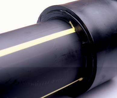
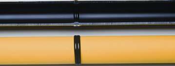
11 Figure 1 Unacceptable Concave Melt Appearance 1 INCORRECT The correct joining force will form a double bead that is rolled over to the surface on both ends. 6. Hold. Hold joining force against the ends until the joint is cool. Maintain fusion pressure against the pipe ends at a minimum cool time rate of 11 minutes per inch of pipe wall thickness. For ambient temperatures above 100 F, additional cooling time may be needed. Do not try to shorten cooling time by applying water, wet cloths or the like. Avoid pulling, installation, pressure testing and rough handling for at least an additional 30 minutes after removal from the fusion machine. For 1 IPS and smaller pipe sizes, only 10 minutes of additional cooling time is required. Heavier wall thickness pipes require longer cooling times. 7. Inspect. On both sides, the double bead should be rolled over to the surface and be uniformly rounded and consistent in size all around the joint. Butt fusion bead dimensional guidelines can be seen in Figure 2. When butt fusing to molded fittings, the fitting-side bead may have an irregular appearance due to the molded part cooling and knit lines. This is acceptable provided the pipe-side bead is correct. One bead may be larger than the other when fusing two dissimilar materials. This is acceptable provided both bead sizes are uniform around their respective pipes. It is not necessary for the internal bead to roll over to the inside surface of the pipe. Manual PP-750 September 2017 Page 10 of 29 September 2017 supersedes all previous editions
12 Figure 2 Butt Fusion Bead Proportions (ASTM F2620) Manual PP-750 September 2017 Page 11 of 29 September 2017 supersedes all previous editions


13 Table 3: Butt Fusion Bead Troubleshooting Guide Observed Condition Double bead v-groove too deep Non-uniform bead size around pipe One bead larger than the other Beads too small Beads too large Rough, sandpaper-like, bubbly, or pockmarked melt bead surface Possible Causes Pressure applied during the heating cycle. Misalignment; defective heating tool; worn equipment; incomplete facing Different bead sizes are expected when joining different material types, such as heat fusion joining MDPE to HDPE pipes. If the two materials being joined are the same, then having one bead being larger than the other bead may be a sign that the component slipped in clamp; that the heating tool may be defective or that there may be incomplete facing; Insufficient heating; insufficient joining force Excessive heating time Hydrocarbon contamination Acceptable Fusions Proper double roll-back bead 2. Proper alignment 3. Proper double roll-back bead Proper alignment 5. No gaps or voids when bent Manual PP-750 September 2017 Page 12 of 29 September 2017 supersedes all previous editions


14 Unacceptable Fusions INCORRECT 2 1 INCORRECT 1. Insufficient heat time; melt bead too small 2. Excessive heat time or pressure applies during heating; melt bead too large 3 4 INCORRECT INCORRECT 3. Pipe angled into fusion unit 4. Improper High-Low alignment INCORRECT INCORRECT Incomplete face off or failure to remove faced off ribbons 6. Incomplete face off Manual PP-750 September 2017 Page 13 of 29 September 2017 supersedes all previous editions
15 BEND BACK TESTING OF BUTT FUSED JOINTS FOR GAS UTILITIES, REFER TO DOT CFR FOR QUALIFYING PERSONS TO MAKE JOINTS. 1. Allow sample joints to cool for no less than one hour. 2. Prepare and cut joint samples into test straps. Please refer to Figure 3 below. For these qualifying procedures, limit the joint samples to pipe wall thickness of no greater than 1 in. (25 mm). WARNING Bend testing of pipes with a wall thickness greater than 1 in. (25 mm) can be dangerous and should be done with an approved bending fixture that supports and contains the pipe during testing. 3. Visually inspect the cut joint for any indications of voids, gaps, misalignment of surfaces that have not been properly bonded during the fusion process. 4. Bend each test strap at the fusion joint with the inside of the pipe facing out until the ends touch. The test strap must be free of cracks and separations within the fusion joint zone. 5. If flaws are observed in the fusion zone, compare appearance with pictures of unacceptable joints. Prepare a new sample joint using correct joining procedure and repeat the qualifying procedure. Figure 3 Butt Bent Strap Test Specimen t = wall thickness Manual PP-750 September 2017 Page 14 of 29 September 2017 supersedes all previous editions
16 SADDLE FUSION SADDLE FUSION TO A PRESSURIZED MAIN (HOT TAPPING) As identified in the introduction, this saddle fusion procedure applies to field fusion of Performance Pipe service saddles, tapping tees and branch saddles. WARNING: The possibility of gas main blowout increases when internal pressure is higher, when the pipe wall is thinner (higher DR) and when the temperature of the main is elevated. When saddle fusing to a pressurized gas main, gas main internal pressure must not exceed pressure limits specified in Federal regulations (MAOP). For Federally regulated gas applications in the United States, main pressure must be reduced for elevated temperature when the main temperature exceeds 100 F (38 C). For Federally regulated gas applications in Canada, main pressure must be reduced for elevated temperature when the main temperature exceeds 23 C (73 F). Saddle fusion to pressurized gas mains is not recommended for 3 IPS (89mm) mains with DR s above 13.5 and 4 IPS (110 mm) and larger mains with DR s above 17. REQUIRED EQUIPMENT A saddle fusion machine (application tool/unit) with appropriate clamps for the main pipe and saddle fitting. Use a main bolster or support for 6 IPS (160 mm) and smaller main pipes. Important: When saddle fusing to a pressurized main, the saddle fusion machine must have a gauge or mechanism that indicates the force applied when the saddle base is pressed against the heating tool or the main. A heating tool with faces contoured and correctly sized for the main pipe and the fitting base. Both serrated and smooth heater faces will produce quality saddle fusions with the serrated heater faces being preferred grit utility cloth. Timing equipment such as a stopwatch or watch with a sweep second hand when fusing to 2 IPS and smaller mains. WARNING: Using improper or faulty equipment, or failing to follow correct saddle fusion procedure during saddle fusion to a pressurized main can result in death, serious injury or property damage. Important: Saddle fusion machines, tools and equipment from different manufacturers will operate differently. Follow the machine manufacturer's instructions for proper use and operation of the equipment. Manual PP-750 September 2017 Page 15 of 29 September 2017 supersedes all previous editions
17 SET-UP PARAMETERS HEATING TOOL SURFACE TEMPERATURE - MINIMUM 490 F MAXIMUM 510 F ( C) Low heating tool temperature can lead to a blowout during saddle fusion to a pressurized main. Before you begin, all points on both heating tool surfaces must be within the prescribed minimum and maximum temperatures where the heating tool surfaces will contact the main or the fitting. Heating tool surfaces must be clean. SADDLE FUSION PARAMETERS Important: Saddle fusion bead-up force, heating force and joining force are printed on the fitting label and can be found in the Performance Pipe fusion force document online. Bead-Up Force. During bead-up, force is applied to form an initial melt pattern on the main and the fitting base. Bead-up ends when melt is visible at the top center of the main on both sides of the heating tool. Bead-up force is usually applied for 3 5 seconds, but no more than about 1/3 of the total heating time. The bead-up force in pounds is the first number (XXX) on the fitting label. See Figure 4. Heating Force. The heating force is always zero. During heating, the fitting, heating tool and main are held together, but without applying force. The heating force is the second number on the fitting label (as depicted in Figure 4 as 0 ). Joining Force. Joining force is applied to the fitting against the main immediately after the heating tool is removed. Joining force is half the bead-up force. The joining force is the third number (ZZZ) on the fitting label. See Figure 4. Joining force must be maintained for the duration of the first cooling period. Caution Never reduce joining force during the first cooling time period. Reducing joining force during the first cooling time period may result in blowout during hot tapping. If the saddle fusion machine force gauge reading rises during the minimum cooling time period, allow it to do so, see Step 4 of the Saddle Fusion Procedure section for minimum cooling time. Maximum Heating Time. The heating tool will be placed on the main. Once the fitting is moved against the heater face AND the Initial Heat Force (see fitting label) is applied, the heating time is started. The heating time ends when the heating tool is removed from in-between the main and the fitting. When hot tapping 2 IPS and smaller mains, a timing device such as a stopwatch or watch with a sweep second hand is necessary for measuring heating time. See Table 4 for Maximum Heating Time. WARNING When saddle fusing to a pressurized main, blowout may occur if maximum heating time is exceeded. Minimum Cooling Time. Cooling time is two successive cooling time periods. During the first cooling time period, joining force is applied with the saddle fusion equipment. At the end of the first cooling time period, the application tool may be removed. During the second cooling time period, the joint must be allowed to cool undisturbed. After the second cooling time period, the service or branch line may be connected, or pressure leak tests or tapping may be conducted. See Step 4 in the procedure for Minimum Cooling Time. WARNING Never reduce joining force during the first cooling time period, even if joining force increases on its own. Manual PP-750 September 2017 Page 16 of 29 September 2017 supersedes all previous editions

18 Figure 4 Example Fitting Label PROCEDURE 1. Prepare. The area of the main pipe where the saddle fusion machine and the fitting will be located must be clean, dry and free of deleterious nicks, gouges or cuts 2. The application tool must fit on the main pipe without interference or restriction from components or appurtenances, fusion beads or the like. Remove dirt and foreign materials from the main pipe surface. If below grade, the excavation must be large enough to install and operate the Saddle Fusion Machine. The main pipe must not be curved tighter than 100 pipe diameters bending radius. WARNING Observe all applicable codes, regulations and safety precautions when working in trenches or other excavations and when working with pressurized gas lines. Install the saddle application tool on the main pipe according to the tool manufacturer s instructions. The saddle application tool should be centered at the location where the fitting will be fused. Abrade the fusion surface of the fitting base and the mating fusion surface of the main pipe with grit utility cloth. On the main surface, abrade a surface area that is the size of the fitting base plus about 1/2-in (13 mm) per side all around. It is necessary to completely remove a thin layer of material from both surfaces. After abrading, brush the residue away with a clean, dry, lintfree, non-synthetic (cotton) cloth. Do not touch abraded and cleaned surfaces with your hands. Regular replacement of the utility cloth is necessary. Worn or dirty utility cloth will not abrade the surface properly. Poor surface preparation can cause poor fusion quality. Install and lightly clamp the fitting in the saddle application tool. (Tapping tee caps may need tightening.) Move the fitting base against the main pipe and apply moderate force (around 100 lbs) to seat the fitting against the main pipe and in the application tool. It may be necessary to wiggle the fitting a little to be sure it is completely seated and squarely aligned against the main. While maintaining force, secure the fitting in the saddle application tool. Move the fitting away from the main pipe. 2. Heat. Verify that the heating tool is between 490 F F. Place the heating tool on the pipe centered beneath the fitting base and immediately lower the fitting against the heater face. Do not slam the fitting against the heating tool. Quickly apply the calculated Initial heat force and begin timing. At the first visual indication of melt between heating tool face and the crown of the pipe, 2 If used, alcohol wipes are used only before abrading the surface, never after abrading the surface. The surface should be wiped dry with a clean, dry, lint-free, non-synthetic (cotton) cloth, or paper towel after using the alcohol wipe. Manual PP-750 September 2017 Page 17 of 29 September 2017 supersedes all previous editions
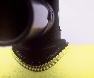
19 reduce force to heat soak force (zero force) and continue timing. Heat the pipe and fitting until the indicated total heating time expires or a melt bead of 1/16 is visible around the fitting base. See Table 4. Important: Use a Flexible Heat Shield for large fittings (>IPS 3 outlet) and large mains (>IPS 6 ) A Flexible Heat Shield prevents the fitting from overheating while heating a thick main pipe. Place the heating tool on the main centered beneath the fitting base, and then place the Flexible Heat Shield between the heating tool and fitting base. (It may be necessary to have an assistant handle the Heat Shield.) Apply initial heat force, then when a melt bead is first visible on the main all around the heating tool faces, release the initial heat force, raise the fitting slightly, remove the Heat Shield, move the fitting against the heating tool face, apply initial heat force and start the heat time. When a melt bead is first visible all around the fitting base (usually about 3 to 5 seconds), reduce to heat soak force (zero). Maintain heat soak force until at least a 1/16 inch bead is present around the fitting base. WARNING Heating and fusing must be performed accurately and quickly, especially when saddle fusing to a pressurized main pipe. Overheating or excessive time between actions can cause a blowout. WARNING Do not interrupt heating to inspect the melt pattern on the main pipe. When fusing to a pressurized main, this can overheat the main pipe and cause a blowout. 3. Join. When the heating time ends, separate the heating tool from the fitting and the pipe and remove the heating tool. Quickly inspect the melt on the pipe and fitting base. Within 3 seconds move the fitting against the pipe and apply the calculated fusion force. 4. Hold. Maintain the fusion force for 5 minutes on IPS 1¼ (42 mm) and for 10 minutes on larger sizes. Cool undisturbed for an additional 30 minutes. During this time avoid pressure testing, rough handling, tapping and connecting to the branch outlet. WARNING Blowout Always join the fitting to a pressurized main pipe after heating. If the fitting is not joined to the main pipe immediately after heating, the pressurized main pipe may rupture. After fusion joining force has been applied, NEVER reduce fusion joining force until the first cooling time period has ended. Do not reduce the application tool joining force setting if the value on the application tool gauge rises. The saddle fusion machine may be removed after the first cooling time period has ended. 5. Inspect. Visually check the fusion bead around the entire fitting base at the main pipe. The fusion bead should be uniformly sized all around the fitting base and should have a characteristic threebead shape. Refer to Image #1 under the Acceptable Fusion section. The first bead is the fitting Manual PP-750 September 2017 Page 18 of 29 September 2017 supersedes all previous editions
20 base melt bead. The second or outermost bead is produced by the edge of the heating tool face on the main. The third or center bead is the main pipe melt bead. The first and third beads should be about the same size all around the fitting base. If the melt on the main pipe or the fitting base was unacceptable, the saddle fusion should not be placed in service. Please see Table 5 for troubleshooting of irregular bead performance and/or appearance. Table 4: Saddle Fusion Parameters Sequence Heater Adapter Surface Temperature Initial Interfacial Pressure Heat Soak Interfacial Pressure Fusion Interfacial Pressure Total Heating Time on Pressure Main 1-1/4 IPS Total Heating Time on Pressure Main 2 IPS Total Heating Time on Non Pressure Main 1-1/4 and 2 IPS Total Heating Time on Pressure/Non Pressure Main 3 IPS and Larger Parameter 500 ± 10 F (260 ± 6 C) 60 ± 6 psi (4.14 ± 0.41 bar); Calculate or See Fitting Label 0 psi; Calculate or See Fitting Label 30 ± 3 psi (2.07 ± 0.20 bar); Calculate or See Fitting Label 15 seconds Max 25 to 35 seconds Max Look for a 1/16 in (1.6 mm) bead around the fitting base Table 5: Saddle Fusion Bead Troubleshooting Guide Observed Condition Non-uniform bead size around fitting base One bead larger than the other Beads too small Beads too large No second bead (or outermost bead) Serrated bead appearance Smooth bead appearance Pressurized main pipe blowout (beside base or through fitting center) Rough, sandpaper-like, bubbly, or pockmarked melt bead surface No third (or center) bead Possible Cause Misalignment; defective heating tool; loose or contaminated heating tool saddle faces; worn equipment; fitting not secured in application tool; heating tool faces not within specified temperature Misalignment; component slipped in clamp; worn equipment; defective heating tool; loose or contaminated heating tool saddle faces; heating tool faces not within specified temperature Insufficient heating; insufficient joining force Excessive heating time; excessive force Incorrect pipe main heating tool face Normal for serrated heating tool faces Normal for smooth heating tool faces Overheating; incorrect heating tool faces; heating tool faces not within specified temperature; taking too much time to start heating (Step 2e), or to remove the heating tool and join the fitting to the main pipe (Step 3g); Hydrocarbon contamination Insufficient joining force Manual PP-750 September 2017 Page 19 of 29 September 2017 supersedes all previous editions


21 Acceptable Fusions 1 ST BEAD 3 RD BEAD 2 ND BEAD Proper alignment, force and melt 2. Proper pipe surface preparation 3. Proper alignment, force and melt 4. Proper pipe surface preparation Melt bead below or parallel with top of fitting base 6. Material pulled from pipe when impact tested No gap or voids when bent 8. No gaps or voids at fusion interface Manual PP-750 September 2017 Page 20 of 29 September 2017 supersedes all previous editions


22 Unacceptable Fusions INCORRECT INCORRECT Insufficient melt and misaligned INCORRECT 2. Bead above base of fitting 3. Excessive melt and force INCORRECT Excessive melt and force 5. Insufficient melt Manual PP-750 September 2017 Page 21 of 29 September 2017 supersedes all previous editions
23 BEND BACK TESTING OF SADDLE FUSED JOINTS FOR GAS UTILITIES, REFER TO DOT CFR FOR QUALIFYING PERSONS TO MAKE JOINTS. 1. Prepare fusion joint samples. Pipe on either side of the fitting should extend at least 6 (150 mm) or 15 times the wall thickness in length. Please refer to Figure 5 below. For these qualifying procedures, limit the joint samples to pipe wall thickness of no greater than 1 in. (25 mm). Observe the joining process to determine that the correct procedure is being followed. WARNING Bend testing of pipes with a wall thickness greater than 1 in. (25 mm) can be dangerous and should be done with an approved bending fixture that supports and contains the pipe during testing. 2. Allow the sample joints to cool for no less than one hour. 3. Cut sample joint lengthwise along the main pipe and through the saddle fitting to prepare a test strap. Please refer to Figure Visually inspect the cut joint for any indications of voids, gaps, misalignment of surfaces that have not been properly bonded during the fusion process. 5. Bend test straps at the fusion joint as pictured above. The test strap joint must be free of cracks and separations within the fusion zone. 6. If flaws are observed in the fusion zone, compare appearance with pictures of unacceptable joints. Prepare new sample joints using correct joining procedure and repeat the qualifying procedure. Alternate Bend Back Testing of Saddle Fused Joints Test a sample joint by impact against the saddle fitting. Failure must occur by tearing the fitting or bending the fitting at least 45º or removing a section of wall from the main pipe. Failure along the fusion bond line is not acceptable. (Federal regulations require impact tests for procedure qualification, but not for individual qualification.) Refer to ASTM F905. Figure 5 Saddle Bent Strap Test Specimen t = wall thickness Manual PP-750 September 2017 Page 22 of 29 September 2017 supersedes all previous editions
24 SOCKET FUSION REQUIRED EQUIPMENT This procedure requires: Chamfering tool, depth gauge (some manufacturers combine chamfering tool and depth gauge), cold ring clamp, heating tool with male and female socket faces, and timing equipment (such as a watch with a second hand). Holding tools are desirable for 2 IPS (90 mm OD) and larger pipe and fittings. Clean work gloves are suggested. Heating tool male and female socket faces should meet ASTM F1056 Socket Fusion Tools for Use in Socket Fusion Joining Polyethylene Pipe or Tubing and Fittings. SET-UP PARAMETERS HEATING TOOL SURFACE TEMPERATURE - MINIMUM 490 F MAXIMUM 510 F ( C) Where heating tool surfaces will contact the main or the fitting, all points on both heating tool surfaces must be within the prescribed minimum and maximum temperatures before you begin. Molten PE material may be cleaned from heating tool faces with a wooden implement such as a tongue depressor. To remove burned or charred material from socket faces, heat the faces, insert a short length of pipe or tubing into the female face and a socket fitting onto the male face. Then unplug the heating iron and let it cool completely. When the pipe or tubing and the fitting are removed from the cold heating tool, the burned or charred material will come off with them. PROCEDURE 1. Clean and Cut. Clean the inside and outside of the pipe and fitting with a clean, dry, lint-free, nonsynthetic (cotton) cloth, or paper towel. Do not touch cleaned surface with your hands. The pipe or tubing end must be squarely cut. If the end is not squarely cut, use a plastic pipe cutter or hand saw and cut the pipe or tubing end squarely. When using a wheel-type pipe cutter, be sure the cutter wheel does not thread down the pipe cut off all partial cuts before fusion. On larger pipes, toe-in may need to be removed before fusion 2. Chamfer. For all pipe and tubing sizes, chamfer the end to remove the sharp outer edge on the OD. Remove all burrs from inside of pipe ends. Make sure the pipe or tubing end is clean, dry and free of foreign substances. Wipe with a clean, dry, lint-free, non-synthetic (cotton) cloth, or paper towel. Do not touch cleaned surfaces with your hands. 3. Round. Place the depth gauge snugly over the chamfered end of the pipe and clamp the cold ring clamp on the pipe OD immediately behind the depth gauge. Remove the depth gauge In socket fusion, there is an interference fit between the pipe or tubing and the socket, that is, the socket is slightly smaller than the pipe. They won t fit together cold. Heating tool faces are tapered which produces a tapered melt. Therefore, the pipe or tubing and the fitting will tend to push away from the heating tool during heating and will tend to push apart Manual PP-750 September 2017 Page 23 of 29 September 2017 supersedes all previous editions
25 when first joined together. It is necessary to hold the pipe and fitting against the heater faces during heating and to hold them together when fusing. When using a socket coupling to join coiled pipe, if possible S the pipes on either side of the coupling to compensate for coil curvature and make it easier to join the second pipe to the coupling. 4. Heat. Verify that the heating tool is between 490 F- 510 F. Push the socket fitting onto the male socket face. DO NOT TWIST. The socket fitting must bottom out completely and be held against the back surface of the male heater face. Then and only then, push the pipe or tubing end into the female socket face. DO NOT TWIST. The cold ring clamp must be completely against the female socket face and held in place. Heating time starts when the cold ring is against the female heater face and when pipe and fitting are fully inserted. Heat the pipe end and the fitting socket for the time required in Table 6. Important: For socket fusion joining of medium density to high density, pre-heat the high density component. This pre-heat time can be found by subtracting the shorter heating time (medium density) from the longer heating time (high density). If heating times are within 10% of each other, the longer heating time may be used for both components Join. At the end of the heating time, quickly remove the pipe and fitting from the Heating Tool simultaneously using a snap action. DO NOT TWIST. Inspect the melt pattern on the pipe and fitting socket. The surfaces should be 100% melted with no cold spots. Within 3 seconds after removing from the heating tool, firmly push the pipe end and the fitting socket straight together, DO NOT TWIST PIPE OR FITTING, until the cold ring clamp makes firm contact with the end of the fitting socket. Important: Remove the pipe and the fitting straight out from the heating tool faces. Do not displace the melt. If the pipe or fitting are removed at an angle or twisted, melt can be displaced, and the joint may leak or fail. Grasp the pipe behind the cold ring clamp. Pulling on the cold ring clamp handle can cause slippage or displace the melt. If the melt is not complete, do not continue with the joint. Cut off the melted pipe end, use a new fitting and start over from Step 1. Do not re-use a melted fitting. If the melt is correct, continue the joining procedure. Grasp the pipe behind the cold ring clamp. Pushing on the cold ring clamp handle can cause slippage or a crooked joint. 3 The Guideline for the joining of unlike materials is based on PPI TN-13/2007 General Guidelines for Butt, Saddle, and Socket Fusion of unlike Polyethylene Pipes and Fittings. Manual PP-750 September 2017 Page 24 of 29 September 2017 supersedes all previous editions
26 6. Hold. Hold the pipe and socket fitting firmly together until the Table 6 cooling time has been met. DO NOT TWIST PIPE OR FITTING. For ambient temperatures 100 F and higher, additional cooling time may be needed. Remove the rounding clamp and inspect the end of the socket fitting at the pipe for a complete impression of the rounding clamp in the melt surface. Allow the joint to cool for an additional 5 minutes before exposing the joint to any type of stress (ex: burial, testing or fusing the other end of the fitting, etc.). Important: Push the pipe and fitting straight together. If joined at an angle or misaligned, the joint may leak or fail. Clean heater faces carefully after each fusion with a wooden implement such as a tongue depressor to remove any molten PE from the male and female socket faces. 7. Inspect. Inspect the end of the socket fitting at the pipe. There should be a clear impression of the cold ring clamp into the melt ring at the end of the fitting with no visible gaps or voids around the pipe at the socket melt ring. The pipe and fitting should be aligned straight with each other. Use Table 7 for common socket fusion problems. If flaws are observed in the joint, find the cause of the flaw and repeat the procedures to prepare a new joint. Important: For installation purposes, the pipe bend radius should be kept to 100 times the outside diameter when a socket fusion fitting is present to avoid over stressing the pipe and/or fitting connection Table 6: Socket Fusion Heating & Cooling Times Pipe Size PE 2406 / PE 2708 PE 3408 / PE 3608 / PE 4710 Heating Time, seconds Cooling Time, seconds Heating Time, seconds Cooling Time, seconds 1/2 CTS /4 CTS CTS /4 CTS /2 IPS /4 IPS IPS /4 IPS /2 IPS IPS IPS IPS Manual PP-750 September 2017 Page 25 of 29 September 2017 supersedes all previous editions
27 Table 7: Socket Fusion Troubleshooting Guide Observed Condition No cold-ring impression in socket fitting melt bead Gaps or voids around pipe at socket fitting edge Wrinkled or collapsed pipe or tubing end (when viewed from inside, or when qualifying lengthwise cut joint) Voids in fusion bond area (when qualifying lengthwise cut joint) Unbonded area on pipe or tubing at end of pipe or tubing (when qualifying lengthwise cut joint) Socket melt extends past end of pipe or tubing (when qualifying lengthwise cut joint) Rough, sandpaper-like, bubbly, or pockmarked melt bead surface Possible Cause Depth gauge not used; cold ring not used, or set at incorrect depth; Insufficient heat time Pipe or fitting not removed straight from heater face (twisting or removing from heater face at an angle); pipe or fitting not inserted straight into each other when fusing; Joining together at an angle; twisting while joining pipe and fitting together; cold ring not used or set too deep Incorrect heating sequence always push the pipe or tubing into the heater after the fitting has been pushed on the heater (inserting the tubing first heats the tubing too long); cold ring set too deep; cold ring not used Pipe or fitting not removed straight from heater face (twisting or removing from heater face at an angle); pipe or fitting not inserted straight into each other when fusing; joining together at an angle; twisting while joining pipe and fitting together; cold ring not used or set too deep Cold ring not used or set too deep Cold ring set too shallow Hydrocarbon contamination Acceptable Appearance Manual PP-750 September 2017 Page 26 of 29 September 2017 supersedes all previous editions


28 Acceptable Fusions Melt bead flattened by cold ring 2. No gaps or voids 3. No gap or voids 4. Proper insertion depth 5. Acceptable internal fusion bead 6. Complete internal melt bead No gap or voids 8. Melt bead flattened by cold ring Manual PP-750 September 2017 Page 27 of 29 September 2017 supersedes all previous editions


29 Unacceptable Fusions 1 2 INCORRECT 1. Improper insertion depth/short stab depth 2. Misalignment INCORRECT INCORRECT INCORRECT Excessive heating 4. Melt bead not flattened against fitting/no cold ring 5. Improper insertion depth/no cold ring 6. Excessive heating 6 Manual PP-750 September 2017 Page 28 of 29 September 2017 supersedes all previous editions
30 BEND BACK TESTING OF SOCKET FUSED JOINTS FOR GAS UTILITIES, REFER TO DOT CFR FOR QUALIFYING PERSONS TO MAKE JOINTS. 1. Prepare fusion joint samples. Pipe on either side of the fitting should extend at least 6 (150 mm) or 15 times the wall thickness in length. Please refer to Figure 6 below. For these qualifying procedures, limit the joint samples to pipe wall thickness of no greater than 1 in. (25 mm). Observe the joining process to determine that the correct procedure is being followed. WARNING Bend testing of pipes with a wall thickness greater than 1 in. (25 mm) can be dangerous and should be done with an approved bending fixture that supports and contains the pipe during testing. 2. Allow the sample joints to cool for no less than one hour. 3. Cut sample joint lengthwise along the main pipe and through the saddle fitting to prepare a test strap. Please refer to Figure Visually inspect the cut joint for any indications of voids, gaps, misalignment of surfaces that have not been properly bonded during the fusion process. 5. Bend test straps at the fusion joint as pictured above. The test strap joint must be free of cracks and separations within the fusion zone. 6. If flaws are observed in the fusion zone, compare appearance with pictures of unacceptable joints. Prepare new sample joints using correct joining procedure and repeat the qualifying procedure. Figure 6 Socket Bent Strap Test Specimen t = wall thickness Manual PP-750 September 2017 Page 29 of 29 September 2017 supersedes all previous editions

31 Contact Information Performance Pipe A division of Chevron Phillips Chemical Company LP 5085 W. Park Blvd., Suite 500, Plano, TX Phone: Fax: Visit Performance Pipe on the web for the latest literature updates: NOTE: By using any Technical Information contained herein, Recipient agrees that said Technical Information is given by Performance Pipe, a division of Chevron Phillips Chemical Company LP for convenience only, without any warranty or guarantee of any kind, and is accepted and used at your sole risk. Recipients are encouraged to verify independently any such information to their reasonable satisfaction. As used in this paragraph, "Technical Information" includes any technical advice, recommendations, testing, or analysis, including, without limitation, information as it may relate to the selection of a product for a specific use and application.
Table of Contents Topic Page Introduction 1 Gas Distribution Products Overview 2 Federal Regulations for Gas Pipe Joining 2 Precautions
 Table of Contents Topic Page Introduction 1 Gas Distribution Products 1 Overview 2 Federal Regulations for Gas Pipe Joining 2 Precautions 3 Static Electricity 3 Electric Tools 4 Protection Against Shear
METROPOLITAN Construction Standard No: UTILITIES DISTRICT
 Page: 1 of 8 A. GENERAL * The Plastic Pipe Institute (PPI) developed standardized butt-fusion procedures which are labeled by the industry as Generic Butt-Fusion Procedures. These procedures have been
Qualification Procedures for making PE 3408 Extra High Molecular Weight Polyethylene Heat Fusion Joints
 Qualification Procedures for making PE 3408 Extra High Molecular Weight YELLOWSTRIPE@ Polyethylene Heat Fusion Joints. BULLETIN NO.106 . Fusion Butt Photographs Fusion Joints. of Qualification Procedures.
Socket Heat Fusion Techniques. A Guide for Instruction and Training in Vanguard Socket Heat Fusion
 Socket Heat Fusion Techniques A Guide for Instruction and Training in Vanguard Socket Heat Fusion TABLE OF CONTENTS This brochure has been developed to assist those responsible for socket fusion joining
HDPE FUSION MANUAL ISCO-PIPE.COM. 100 Witherspoon Street 2West Louisville, Kentucky T F
 ISCO-PIPE.COM HDPE FUSION MANUAL 100 Witherspoon Street 2West Louisville, Kentucky 40202 T. 800.345.4726 F. 800.831.4726 Copyright 2018 ISCO Industries, Inc. All rights reserved. Copyright 2018 ISCO Industries,
HDPE FUSION MANUAL ISCO-PIPE.COM. 100 Witherspoon Street 2West Louisville, Kentucky T F
 ISCO-PIPE.COM HDPE FUSION MANUAL 100 Witherspoon Street 2West Louisville, Kentucky 40202 T. 800.345.4726 F. 800.831.4726 Q3 2017 Welcome to the ISCO Industries, Inc. (ISCO) Fusion Manual. After gathering
THE GOOD GUIDE TO BUTT FUSION JOINTING....Connect
 THE GOOD GUIDE TO BUTT FUSION JOINTING...Connect THE GOOD GUIDE TO BUTT FUSION JOINTING This guide will provide basic information to enable the operative to: Equipment required: Understand the equipment
Proweld Equipment Owner & Maintenance Manual Halar Shop 6 W900 (Widos)
") Proweld Equipment Owner & Maintenance Manual Halar Shop 6 W900 (Widos) 35 Green Street, PO Box 653, Malden, MA 02148 Tel: (781) 321-5409 - Fax (781) 321-4421 - Toll Free: (800) 343-3618 www.asahi-america.com
Proweld Equipment Owner & Maintenance Manual Halar Shop 6 W900 (Widos) 35 Green Street, PO Box 653, Malden, MA 02148 Tel: (781) 321-5409 - Fax (781) 321-4421 - Toll Free: (800) 343-3618 www.asahi-america.com
PRODUCT CATALOGUE Avenue Edmonton, AB Canada T6E 5Z7. Toll Free: Phone: (780) Fax: (780)
 Fax: (780)") PRODUCT CATALOGUE 9333 45 Avenue Edmonton, AB Toll Free: 1-800-272-9693 Phone: (780) 436-1930 Fax: (780) 435-4849 info@can-con.com BUTT FUSION EQUIPMENT MicroMax weighs only 3.5 pounds (1.6kg) for ½ CTS
PRODUCT CATALOGUE 9333 45 Avenue Edmonton, AB Toll Free: 1-800-272-9693 Phone: (780) 436-1930 Fax: (780) 435-4849 info@can-con.com BUTT FUSION EQUIPMENT MicroMax weighs only 3.5 pounds (1.6kg) for ½ CTS
Installation Instructions. For the 18 Built-In Dishwasher and Front Color Panels
 Installation Instructions For the 18 Built-In Dishwasher and Front Color Panels Printed in USA 154232102 Before You Begin DO NOT INSTALL DISHWASHER UNTIL YOU HAVE READ ALL INSTRUCTIONS. FOR YOUR SAFETY,
Proweld Equipment Owner & Maintenance Manual
 Proweld Equipment Owner & Maintenance Manual FIELD 12 TRENCH (Widos 4900) Tel: (781) 321-5409 - Fax (781) 321-4421 - Toll Free: (800) 343-3618 www.asahi-america.com - asahi@asahi-america.com Direct Sales:
Bar Fridge USER MANUAL MB46W
 Bar Fridge USER MANUAL MB46W CONTENTS Safety information... 2-3 Identifying parts of the fridge... 4 Transporting... 5 Installation... 5 Reversing the door... 6 Operating instructions... 7 Cleaning &
Proweld Equipment Owner & Maintenance Manual Maxiplast (Widos Shop 6)
") Proweld Equipment Owner & Maintenance Manual Maxiplast (Widos Shop 6) Tel: (781) 321-5409 - Fax (781) 321-4421 - Toll Free: (800) 343-3618 www.asahi-america.com - asahi@asahi-america.com Direct Sales:
Proweld Equipment Owner & Maintenance Manual Maxiplast (Widos Shop 6) Tel: (781) 321-5409 - Fax (781) 321-4421 - Toll Free: (800) 343-3618 www.asahi-america.com - asahi@asahi-america.com Direct Sales:
ENRGY CURB APPLICATION GUIDE FOR TPO ROOFING SYSTEMS
 1. Introduction The ENRGY Curb mounting system is a lightweight, nonpenetrating, roof-integrated, photovoltaic (PV) mounting system designed to maintain roof integrity and maximize power density. This
Flame Retardant Polyethylene Tubing
 Flame Retardant Polyethylene Tubing Classified Under U.L. 1820. Performance Pipe DRISCOPLEX 2600 Instube Flame Retardant (FR) Polyethylene Tubing For Pneumatic Instrument Controls PERFORMANCE PIPE is the
K 2.97 M. Specifications Operating pressure, max PSI Water volume GPM Voltage V Amp draw AMPS
 K 2.97 M High Pressure Washer Operator Manual Overview... 2 Important Precautions... 3-4 Assembly Instructions... 4 Operating Instructions... 5 GFCI Instructions... 6 Using the Accessories... 6 Working
STATIC ELIMINATOR I443A INSTRUCTION MANUAL
 STATIC ELIMINATOR I443A INSTRUCTION MANUAL Thank you for purchasing a Static Eliminator. It is designed to eliminate the static charge from a charged object. Please read this manual before operating the
Installation Instructions Part No
 Heat Exchanger Cell Kit Cancels: New Installation Instructions Part No. 326600-751 IIK-310A-45-6 6-02 NOTE: Read the entire instruction manual before starting the installation. SAFETY CONSIDERATIONS Installing
K Specifications. Max. Water Volume
 K 2.75 High Pressure Washer Operator Manual Overview... 2 Precautions... 2-4 Assembly Instructions... 4 Operating Instructions... 5 Using the Accessories... 6 Working with Detergents... 7 Shut Down and
Installation Instructions
 Installation Instructions For the 18" Built-In Dishwasher Sears, Roebuck and Co. Sears Canada, Inc. Hoffman Estates, IL 60179 U.S.A. Toronto, Ontario, Canada M5B 2B8 154435201 Before You Begin DO NOT INSTALL
Pneumatic Tubing POLYTUBING O.D. 5/32"
 Pneumatic Tubing POLYTUBING O.D. 5/32" 1/4" 3/8" 1/2" PART NR COLOR COIL LENGTH MASTER PACK MASTER PACK WT. 1063636 TWIN TUBE 500' 1000' 16# 1063635 BLACK 500' 2000' 17# 1063641 BLUE 500' 2000' 17# 1063765
DUOPEX WATER MANUAL mm
 DUOPEX WATER MANUAL 32-63mm The DUOPEX WATER Pipe and Fitting System is designed for 32mm- 63mm potable hot and cold water applications. This revolutionary alternative for the professional plumber, makes
Cased Aluminum Coils "Dedicated Upflow / Downflow" Convertible to horizontal with separately purchased kit
 18-AD32D1-3 Cased Aluminum Coils "Dedicated Upflow / Downflow" Convertible to horizontal with separately purchased kit Upflow models: 4PXCAU24BS3HAA 4PXCBU24BS3HAA 4PXCBU30BS3HAA 4PXCCU30BS3HAA 4PXCBU36BS3HAA
POTABLE PIPING SYSTEM
 POTABLE PIPING SYSTEM Designed Especially for Contractors PRODUCT INSTALLATION GUIDE BOW SUPERPEX JUne 2017 PRODUCT INSTALLATION GUIDE IMPORTANT NOTICE The information in this manual was gathered from
2/4TXCC037BC3HCA 2/4TXCB042BC3HCA 4TXCC044BC3HCA 2/4TXCC043BC3HCA 2/4TXCB048BC3HCA
 18- AH39D1-4 Cased Aluminum "Convertible" Coils 2/4TXCA018BC3HCA 2/4TXCA024BC3HCA 2/4TXCB025BC3HCA 2/4TXCB031BC3HCA 4TXCB032BC3HCA 2/4TXCB036BC3HCA ALL phases of this installation must comply with NATIONAL,
INSTALLATION GUIDE Dual Fuel Ranges
 INSTALLATION GUIDE Dual Fuel Ranges Contents Wolf Dual Fuel Ranges......................... 3 Safety Instructions............................ 4 Dual Fuel Range Specifications.................. 5 Dual Fuel
Model K 280 M Part No
 Model K 280 M Part No. 1.189-205.0 High Pressure Washer Operator Manual Overview...................................1 Precautions................................1-3 Assembly Instructions.........................3
INSTRUCTIONS FOR USE PORTABLE VACUUM SYSTEM LEI Part # s / , , , IMPORTANT INFORMATION
 INSTRUCTIONS FOR USE PORTABLE VACUUM SYSTEM LEI Part # s / 27-009, 27-010, 27-015, 27-020 IMPORTANT INFORMATION UNATHORIZED CHANGES OR ALTERATIONS TO ANY LINCOLN PORTABLE VACUUM SYSTEM WILL AUTOMATICALLY
K Specifications. Max. Water Volume
 K 2.35 High Pressure Washer Operator Manual Overview... 2 Precautions... 2-4 Assembly Instructions... 4 Operating Instructions... 5 Using the Accessories... 6 Working with Detergents... 7 Shut Down and
Installation Manual. Vent Kit for Condensing Tankless Gas Water Heater
 Installation Manual NORITZ AMERICA CORPORATION Vent Kit for Condensing Tankless Gas Water Heater Model: N-FlexKit2"-35 Applicable Model NRC663-FSV Potential dangers from accidents during installation and
INSTALLATION MANUAL. Split-type Air Conditioner (Cooling and Heating) Outdoor Unit UQB09JJWC UQB12JJWC. Indoor Unit AQB09JJWC AQB12JJWC
 Outdoor Unit UQB09JJWC UQB12JJWC. Indoor Unit AQB09JJWC AQB12JJWC") AQB09JJ6WC_IM_E_2585 2006.4.17 4:26 PM Page 17 INSTALLATION MANUAL Indoor Unit AQB09JJWC AQB12JJWC Outdoor Unit UQB09JJWC UQB12JJWC ENGLISH FRANÇAIS ESPAÑOL Split-type Air Conditioner (Cooling and Heating)
AQB09JJ6WC_IM_E_2585 2006.4.17 4:26 PM Page 17 INSTALLATION MANUAL Indoor Unit AQB09JJWC AQB12JJWC Outdoor Unit UQB09JJWC UQB12JJWC ENGLISH FRANÇAIS ESPAÑOL Split-type Air Conditioner (Cooling and Heating)
INSTRUCTION MANUAL W-400
 USE and MAINTENANCE INSTRUCTION MANUAL Bellaria WBX WB GRAVITY SPRAY GUN Series LPH-400 WB en it fr es pt de se TECHNICAL DATA Classic Plus Series LPH-400 (LVLP) Classic Plus Nozzle_Needle set Combination
infrared paraffin / kerosene / diesel heater
 instructions for infrared paraffin / kerosene / diesel heater model no: IR20.V3 Thank you for purchasing a Sealey product. Manufactured to a high standard, this product will, if used according to these
Owner s Manual. FMI BRANDS INC th Avenue Surrey, B.C. Canada V3Z 3V7 Toll Free Fax Model number FMPPC2A
 Owner s Manual Model number FMPPC2A Series number 890 FMI BRANDS INC. 309-19133 26th Avenue Surrey, B.C. Canada V3Z 3V7 Toll Free 1-888-514-1663 Fax 1-888-797-9931 Owner & Safety Manual Model number FMPPC2A,
Gas Connector Installation Instructions
 Gas Connector Installation Instructions 6015 Enterprise Drive Export, PA 15632 USA 1-800-DORMONT (367-6668) (724) 733-4800 Fax (724) 733-4808 www.dormont.com Safety Precautions - Read warnings carefully
INSTALLATION INSTRUCTIONS TXV Coils for Manufactured Housing EMA
 TXV Coils for Manufactured Housing EMA NOTE: Read the entire instruction manual before starting the installation. SAFETY CONSIDERATIONS Improper installation, adjustment, alteration, service, maintenance,
Cased Aluminum "Convertible" Coils 4TXCB003CC3HC** 4TXCB004CC3HC** 4TXCC005CC3HC** 4TXCC006CC3HC**
 18- AH44D1-4 Cased Aluminum "Convertible" Coils 4TXCB003CC3HC 4TXCB004CC3HC 4TXCC005CC3HC 4TXCC006CC3HC 4TXCC007CC3HC 4TXCC008CC3HC 4TXCD009CC3HC 4TXCD010CC3HC May be "A" or "B" ALL phases of this installation
model No: ir20.v2 FUSE
 InstructioNS for: model No: ir20.v2 INFRARED PARAFfIN / KEROSENE / diesel HEATER 70000Btu 230V Thank you for purchasing a Sealey product. Manufactured to a high standard this product will, if used according
English. Your Model Number is: HD1500 IMPORTANT
 Your Model Number is: HD1500 IMPORTANT Attention Valued Customer: The serial number of your machine and date of purchase is necessary information to facilitate warranty claims and the ordering of replacement
Easy-Lam School Budget Roll Laminator
 DO NOT DISCARD BOX! (If for any reason you need to ship your machine back and you discard your box you will be responsible for purchasing another one plus any freight charges to ship the box to you) Easy-Lam
Installation Instructions
 Installation Instructions Built-In Dishwasher If you have questions, call 800-944-9400(US),800-245-8352(Canada)or visit our website at: www.frigidaire.com BEFORE YOU BEGIN Read these instructions completely
HOUSEHOLD FREEZER 048-GM-48303/048-GM-48304/048-GM-48305
 HOUSEHOLD FREEZER 048-GM-48303/048-GM-48304/048-GM-48305 TABLE OF CONTENTS NAMES OF THE PARTS 2 IMPORTANT SAFETY INSTRUCTIONS 3 INSTALLATION INSTRUCTIONS BEFORE USING YOUR FREEZER. 3 INSTALLING YOUR FREEZER
Operator s Manual. Fusion Machine SIDEWINDER. Manual: SW00301 Revision: M 05/17. Patent No. 4,533,424
 Operator s Manual Fusion Machine SIDEWINDER Patent No. 4,533,424 Manual: SW00301 Revision: M 05/17 This product and other products could be protected by patents or have patents pending. All the latest
TROUBLESHOOTING VANGUARD
 TROUBLESHOOTING VANGUARD IMPORTANT: Only a qualified Service Person should service internal components or electrical wiring. WARNING: Disconnect electrical power to the Unit to prevent personal injury
INSTALLATION MANUAL. Split-type Air Conditioner (Cooling and Heating) Indoor Unit AQB18J6WC AQB24J2WC. Outdoor Unit UQB18J6WC UQB24J2WC
 Indoor Unit AQB18J6WC AQB24J2WC. Outdoor Unit UQB18J6WC UQB24J2WC") AQB8J6WC_IM_E_25864 2006.4.4 3:29 PM Page 7 INSTALLATION MANUAL Indoor Unit AQB8J6WC AQB24J2WC Outdoor Unit UQB8J6WC UQB24J2WC ENGLISH FRANÇAIS ESPAÑOL Split-type Air Conditioner (Cooling and Heating)
AQB8J6WC_IM_E_25864 2006.4.4 3:29 PM Page 7 INSTALLATION MANUAL Indoor Unit AQB8J6WC AQB24J2WC Outdoor Unit UQB8J6WC UQB24J2WC ENGLISH FRANÇAIS ESPAÑOL Split-type Air Conditioner (Cooling and Heating)
Multi-Function Cooktop
 INSTALLATION GUIDE Multi-Function Cooktop Contents Wolf Multi-Function Cooktop.................... 3 Multi-Function Cooktop Specifications............ 4 Multi-Function Cooktop Installation...............
Installation Requirements for Models:
 900 & 9100 Series Refrigerators Installation Requirements for Models: 9162 9163 9182 9183 962 963 982 983 WARNING Improper installation, adjustment, alteration, service, or maintenance can cause injury
Please read the following installation instructions first after purchasing this product or transporting it to another location.
 9 Installation Overview Please read the following installation instructions first after purchasing this product or transporting it to another location. 1 Unpacking your refrigerator 2 Choosing the proper
WHEELED STORED PRESSURE
 OWNERS SERVICE MANUAL NO. 19795 INSTALLATION, OPERATING & SERVICING INSTRUCTIONS All fire extinguishers should be installed, inspected and maintained in accordance with the National Fire Protection Association
INFRARED PARAFfIN / KEROSENE / model No: ir20.v2 1. SAFETY INSTRUCTIONS RECOMMENDED FUSE RATING: 5AMP
 InstructioNS for: INFRARED PARAFfIN / KEROSENE / diesel HEATER model No: ir20.v2 Thank you for purchasing a Sealey product. Manufactured to a high standard this product will, if used according to these
TT3000 and TT5000 Series
 TT3000 and TT5000 Series Bulk Sensing Cable Installation Instructions General Notes Do s and Don ts General Information These instructions detail techniques used to install TT3000 or TT5000 bulk sensing
INSTALLATION INSTRUCTIONS TXV Horizontal Duct Coils EHD
 TXV Horizontal Duct s EHD These instructions must be read and understood completely before attempting installation. It is important that the Blower and Duct System be properly sized to allow the system
Installation, Operation and Maintenance LOK-FLANGE Multitube Heat Exchangers
 Bulletin 1200/4 (Revised 5/12) Installation, Operation and Maintenance LOK-FLANGE Multitube Heat Exchangers INNOVATORS IN HEAT TRANSFER I. INSTALLATION OF HEAT EXCHANGERS A. HEAT EXCHANGER SETTINGS 1)
Air Filter. Filter for Removing Dust and Drain in Compressed Air. Filter for Drain and Dust (Filtering Accuracy: 5µm)
") http://www.pisco.co.jp AIR PREPARATION ACTUATOR PLARAILCHAIN HARMO ROBOT PARTS Filter for Removing Dust and Drain in Compressed Air Air Filter 220 Filter for Drain and Dust (Filtering Accuracy: 5µm) Resin-made
http://www.pisco.co.jp AIR PREPARATION ACTUATOR PLARAILCHAIN HARMO ROBOT PARTS Filter for Removing Dust and Drain in Compressed Air Air Filter 220 Filter for Drain and Dust (Filtering Accuracy: 5µm) Resin-made
Top Control Dishwasher
 INSTALLATION GUIDE Top Control Dishwasher NS-DWH2BS8/NS-DWH2SS8/NS-DWR2BS8/NS-DWR2WH8/NS-DWR2SS8 Before using your new product, please read these instructions to prevent any damage. Contents Introduction......................................................................................................
Avery Dennison Troubleshooting Guide Instructional Bulletin #8.34 Revised: May 2011
 Introduction Screen printing is one of the most complex means of image reproduction due to the many variables in substrate, ink chemistries, and application techniques. Continual adjustments are frequently
Installation. Leveling
 Your refrigerator was packed carefully for shipment. Remove and discard shelf packaging and tape. Do not remove the serial plate. Location Do not install refrigerator near oven, radiator or other heat
Model ESFR-17 Dry Type Pendent Sprinklers Early Suppression Fast Response 16.8 K-factor General Description
 Technical Services 800-381-9312 +1-401-781-8220 www.tyco-fire.com Model ESFR-17 Dry Type Pendent Sprinklers Early Suppression Fast Response 16.8 K-factor General Description The TYCO Model ESFR-17 Dry
Model K 330 M Part No
 Model K 330 M Part No. 1.994-916.0 High Pressure Washer Operator Manual Overview..................................1 Precautions...............................1-3 Assembly Instructions.........................3
GEOMEMBRANE FIELD INSTALLATION
 GEOMEMBRANE FIELD INSTALLATION CONTENTS Introduction Quality Control and Quality Assurance Types of lining systems Basic Lining Design Executive Lining Design Basic Lining Design Specification Executive
TECHNICAL DATA. Wet 26a. February 22, 2009
 February 22, 2009 Wet 26a 1. DESCRIPTION The Viking Alarm Check Valve serves as a check valve by trapping pressurized water above the clapper and preventing reverse flow from sprinkler piping. The valve
positions, side by side, end to end and Tee configurations. and utility pedestals
 The TOASTER Infrared Ground Thawing Equipment by Serious Thermal Products Ltd., is a propanefired, electrically operated infra-red ground thawing device specifically designed to remove frost from frozen
Owner s Manual. FMI BRANDS INC th Avenue Surrey, B.C. Canada V3Z 3V7 Toll Free Fax Model number FMPPC2F
 Owner s Manual Model number FMPPC2F Series number 863 D.863.000.V0 FMI BRANDS INC. 309-19133 26th Avenue Surrey, B.C. Canada V3Z 3V7 Toll Free 1-888-514-1663 Fax 1-888-797-9931 Owner & Safety Manual Model
Dishwasher Installation Instructions DW 24XT/DW 24XV
 Dishwasher Installation Instructions DW 24XT/DW 24XV Installation Instructions Dishwasher BEFORE YOU BEGIN Read these instructions completely and carefully. IMPORTANT Observe all governing codes and ordinances.
Built-In Dishwasher. Installation Instructions. BEFORE YOU BEGIN Read these instructions completely and carefully. IMPORTANT The dishwasher MUST be
 Installation Instructions Built-In Dishwasher If you have questions, call 800.GE.CARES (800.432.2737) or visit our website at: www.ge.com BEFORE YOU BEGIN Read these instructions completely and carefully.
DAIKIN AIR CONDITIONER
 3P226011-1A M07B242A DAIKIN AIR CONDITIONER Two-dimensional bar code is a code for manufacturing. Safety Precautions (1) Read these Safety Precautions carefully to ensure correct installation. This manual
Wall Mount Electric Fireplace
 Wall Mount Electric Fireplace User Guide Thank you for purchasing the Ivation Wall Mount Electric Fireplace. This User Guide is intended to provide you with guidelines to ensure that operation of this
Model K 520 M Part No
 Model K 520 M Part No. 1.069-680.0 High Pressure Washer Operator Manual Overview... 2 Precautions... 2-4 Assembly Instructions... 4 Operating Instructions... 5 Using the Accessories... 6 Working with Detergents...
Model No: Little Devil II (inc ss)
") GAS HEATER Model No: Little Devil II (inc ss) PART NO: 6926020, 6926025 (SS) OPERATION & MAINTENANCE INSTRUCTIONS LS1213 INTRODUCTION Thank you for purchasing this CLARKE Gas Heater. Before attempting
GAS HEATER Model No: Little Devil II (inc ss) PART NO: 6926020, 6926025 (SS) OPERATION & MAINTENANCE INSTRUCTIONS LS1213 INTRODUCTION Thank you for purchasing this CLARKE Gas Heater. Before attempting
Owner s Manual OUTDOOR LIVING PERFECTED TONGA TORCH PORTABLE PROPANE
 Owner s Manual OUTDOOR LIVING PERFECTED LP Cylinder not included Model number FMTT-1000 FMI BRANDS INC. 107 19052 26th Avenue Surrey, B.C. Canada V3Z 3V7 Toll Free 1-888-514-1663 Fax 1-888-797-9931 Owner
ELECTRIC STOVE HEATER Models: FS2213B
 ELECTRIC STOVE HEATER Models: FS2213B OWNER S MANUAL WARNING Read and understand this entire owner s manual, including all safety information, before plugging in or using this product. Failure to do so
Installation Instructions
 GE Consumer & Industrial Appliances Installation Instructions Junction Box Cover Within this user bag, you will find a junction box cover and a #10 hex head screw used to attach the junction box cover
INSTALLATION GUIDE AND CHECKLIST
 INSTALLATION GUIDE AND CHECKLIST CLOCK SPRING SNAP WRAP November 2017 Copyright Clock Spring Company, L.C. TABLE OF CONTENTS a Snap Wrap Information...i Inspection Checklist...iii Snap Wrap Contents...1
ELECTRIC FLAT PANEL FIREPLACE HEATER
 ELECTRIC FLAT PANEL FIREPLACE HEATER Model Numbers: 80-2000A-42 OWNER S MANUAL AC 120V 60Hz 1500W WARNING Read and understand this entire owner s manual, including all safety information, before plugging
CT-930CH, CT-930LPCH and CT-940CH TABLE OF CONTENTS
 CT-930CH, CT-930LPCH and CT-940CH PA22141A01 Rev. 03 5-2012 REMOTE HYDRAULIC COMPRESSION TOOLS Panduit Corp. 2012 TABLE OF CONTENTS SYSTEM SPECIFICATIONS... 1 OPTIONAL ACCESSORIES... 2 PRECAUTIONS AND
ULTRASONIC HUMIDIFIER
 To Buy: Visit www.sylvane.com or call (800) 934-9194 For Product Support: Contact Sunpentown at 1-800-330-0388 ULTRASONIC HUMIDIFIER [ADORABLE MONKEY] To prolong the life of this humidifier, using distilled
INSTANT HOT WATER DISPENSER
 INSTANT HOT WATER DISPENSER Tank Installation Materials required (not provided) 2 mounting bracket screws (and 2 plastic anchors if attaching to drywall) Shut-Off valve and T fitting Components When you
Continental Industries STEEL COUPLINGS or FAX Visit
 Continental Industries STEEL COUPLINGS 1-800-558-1373 or FAX 1-800-788-1668 Visit www.conind.com ABOUT US Our Company Continental Industries, headquartered in Tulsa, Oklahoma, was formed in 1958 and is
INSTALLATION INSTRUCTIONS TXV Horizontal Duct Coils EHD
 TXV Horizontal Duct s EHD These instructions must be read and understood completely before attempting installation. It is important that the Blower and Duct System be properly sized to allow the system
IMPORTANT SAFETY INFORMATION! WARNING ALWAYS keep electric cords, home furnishings, drapes, clothing, papers, or other combustibles at least 3 feet (0
 Electric Fireplace Factory Model: EF-30D CONSUMER SAFETY INFORMATION Read this manual before installing and operating this appliance Failure to follow these instructions may result in electric shock, fire
USE and MAINTENANCE INSTRUCTION MANUAL GRAVITY. WS-400 EVO LS-400 Entech. SPRAY GUN Series. en it fr es pt de se
 USE and MAINTANCE INSTRUCTION MANUAL WS-400 EVO LS-400 Entech GRAVITY SPRAY GUN Series en it fr es pt de se TECHNICAL DATA WS-400 WS-400 EVO WS-400 Clear WS-400 Base WS-400-1301 EVO 1.3 170 365 260 WS-400-1401
For cleaning machines, parts & supplies click/visit Electrolux Home Care Products Ltd.
 Sanitaire 1.5 GALLON Carpet Spotter SC6075A Part No. SC6075A Rev 2 (9/13) Owner s Guide IMPORTANT Do not return this product to the store. Call 1-800-800-8975* Monday - Friday 8:00 AM to 7:30 PM and Saturday
DSSLF2X04H 2 IN 1. Intelligent Lead Free Soldering Station. OPERATION and MAINTENANCE MANUAL
 401H000898 DSSLFX04H Intelligent Lead Free Soldering Station IN 1 OPERATION and MAINTENANCE MANUAL Thank you for purchasing a lead free soldering station. It is designed for lead free soldering. Please
DUAL VOLTAGE ICE BOX CONVERSION SYSTEM 120 VOLTS A.C. & 12/24 VOLTS D.C. MODELS: SCQT-4408F-U1-L SCQT-4408F-U1-I OWNER'S GUIDE
 DUAL VOLTAGE ICE BOX CONVERSION SYSTEM 120 VOLTS A.C. & 12/24 VOLTS D.C. MODELS: SCQT-4408F-U1-L SCQT-4408F-U1-I OWNER'S GUIDE SAWAFUJI ELECTRIC CO., LTD. GENERAL: This appliance is designed to convert
"S" SERIES IMMERSIBLE PUMP OWNER'S MANUAL INSTALLATION OPERATION PARTS Models S12 S16
 Webster Pumps "S" SERIES IMMERSIBLE PUMP OWNER'S MANUAL INSTALLATION OPERATION PARTS Models S12 S16 PLEASE READ THE FOLLOWING INFORMATION PRIOR TO INSTALLING AND USING Webster PUMPS or HAYWARD VALVES,
INSTALLATION INSTRUCTIONS TXV Horizontal Slab Coils WLSH
 TXV Horizontal Slab Coils WLSH These instructions must be read and understood completely before attempting installation. It is important that the Blower and Duct System be properly sized to allow the system
Model K205 M Plus Part No
 Model K205 M Plus Part No. 1.223-820.0 High Pressure Washer Operator Manual Overview..................................1 Precautions...............................1-3 Assembly Instructions.........................3
Patterson/AMT Inline Circulator Pump Refer to pump manual for General Operating and Safety Instructions.
 Please read and save this Repair Parts Manual. Read this manual and the General Operating Instructions carefully before attempting to assemble, install, operate or maintain the product described. Protect
OWNER'S SERVICE MANUAL NO INSPECTION, MAINTENANCE AND RECHARGE
 FOAM FIRE EXTINGUISHERS MODEL 254-6 LITER AFFF FOAM WITH SPRAY NOZZLE Model 250 2 ½ GAL.LON AFFF FOAM WITH ASPIRATED NOZZLE MODEL 252 2 ½ GAL.LON FFFP (ALCOHOL RESISTANT) FOAM WITH ASPIRATED NOZZLE OWNER'S
ELECTRIC HEDGE TRIMMER
 ELECTRIC HEDGE TRIMMER 60-3014-6 Owner's Manual TOLL-FREE HELPLINE: 1 866 523-5218 IMPORTANT: Read all safety rules and instructions carefully before using this product. TABLE OF CONTENTS SPECIFICATIONS...
Owner s Manual. FMI BRANDS INC Avenue Surrey, B.C. Canada V3Z 3V7 Toll Free Fax Model number FMPPC2F
 Owner s Manual Model number FMPPC2F Series number 863 2017 FMI Brands Inc. Patent Pending D.863.000.V3 FMI BRANDS INC. 107 19052 26 Avenue Surrey, B.C. Canada V3Z 3V7 Toll Free 1-888-514-1663 Fax 1-888-797-9931
1993 Specifications CSJ SPECIAL SPECIFICATION ITEM Impermeable Liner
 1993 Specifications CSJ 0128-01-085 SPECIAL SPECIFICATION ITEM 5327 Impermeable Liner 1. Description. This Item shall govern for the furnishing and installation of the impermeable liner (geomembrane) shown
Packaged Heat Pumps. Owner s Guide to Operating and Maintaining Your Heat Pump
 Packaged Heat Pumps Owner s Guide to Operating and Maintaining Your Heat Pump NOTE TO EQUIPMENT OWNER: For your convenience, please record the model and serial numbers of your new equipment in the spaces
INSTALLATION, OPERATION, AND MAINTENANCE MANUAL
 INSTALLATION, OPERATION, AND MAINTENANCE MANUAL TUBE AXIAL FANS BTA, WTA, HTA, DDA The purpose of this manual is to aid in the proper installation and operation of the fans. These instructions are intended
K 3.97 M. Specifications or visit our website: In USA call: Part No
 K 3.97 M High Pressure Washer Operator Manual Overview... 2 Precautions... 2-4 Assembly Instructions... 4-5 Operating Instructions... 5-6 GFCI Instructions... 6 Using the Accessories... 6 Working with
Installation Instructions
 Installation Instructions Built-In Dishwasher If you have questions, call 800-GECARES or visit our website at: www.geappliances.com BEFORE YOU BEGIN Read these instructions completely and carefully. IMPORTANT
SENJU SPRINKLER CO., LTD.
 Page:1 of 8 SENJU SPRINKLER CO., LTD. Residential, Pendent Sprinkler Model FR-RES K-Factor: 4.9 SIN: SS4451 GENERAL DESCRIPTION The Model FR-RES Residential Pendent and Recessed Pendent Sprinklers are
INSTALLATION. Glass Panel Doors (select models) CAUTION
 CAUTION") Location Do not install refrigerator near oven, radiator or other heat source. If not possible, shield refrigerator with cabinet material. Do not install where temperature falls below 55 F (13 C) or rises
Location Do not install refrigerator near oven, radiator or other heat source. If not possible, shield refrigerator with cabinet material. Do not install where temperature falls below 55 F (13 C) or rises
Danfoss Self-limiting Heating Cables SLPG-10/26/33, SLPG-18, SLHW-55/70, SLPH-10
 MAKING MODERN LIVING POSSIBLE Installation Guide SLPG-10/26/33, SLPG-18, SLHW-55/70, SLPH-10 www.eh.danfoss.com Table of Contents 1 Introduction............................................. 3 1.1 Self-limiting
Joining Large PE Pipes in No Time at All: Integration of large connecting lines made easy
 SAFE JOINING TECHNOLOGY ON A GRAND SCALE FRIALEN XL Offprint Joining Large PE Pipes in No Time at All: Integration of large connecting lines made easy by Dipl.-Ing. (FH) Robert Eckert Technical journal