SolaStat TM -Plus-ET. Installation Guide FOR QUALIFIED PERSONNEL ONLY
|
|
|
- Adam George
- 6 years ago
- Views:
Transcription


1 SolaStat TM -Plus-ET Installation Guide FOR QUALIFIED PERSONNEL ONLY Version1.2 July 2011
2 Table of Contents The Display Panel... 1 Functions... 2 Using Your SolaStat TM -Plus-ET... 4 Before Installation... 6 Mounting the SolaStat TM -Plus-ET... 9 Mounting the Sensors Installation and Wiring Powering Up Installer Programming Sensor Maintenance SolaStat TM -Plus-ET Plumbing Issues Trouble Shooting Guide SolaStat TM -Plus-ET Specifications For technical help contact your distributor. Distributor Details: Contact: Phone: Address: Senztek Holdings Ltd Table of Contents Installation Guide


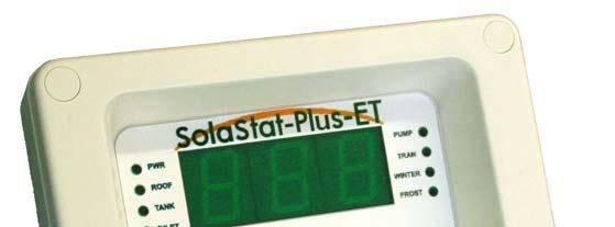
3 THE DISPLAY PANEL When the ROOF light is on, the temperature of the collector sensor in 0 C will be displayed. When the TANK light is on, the temperature of the tank in 0 C will be displayed. Power light indicates that the unit has power. When the t appears at the left side of the screen, it indicates the tank has reached the preset max temperature. The PUMP light is on when solar heated collector water is being transferred to the tank. The TRAN light indicates that Energy Transfer Pump is turned on to circulate water to an external load. It will be turned off when the Energy Transfer Off temperature is reached. When the INLET light is on, the temperature of the inlet in 0 C will be displayed. The WINTER light indicates that the Winter Mode is triggered. When it is off, the unit is in Summer Mode. PUMP Button Press and hold to make the pump run. During programming this button is used to increase value. When the PUMP and FROST lights are on, the pump is circulating water to stop the collector from freezing. TRAN Button Press it to initiate an energy transfer when the tank temperature is above the parameter ET off value. During programming this button is used to decrease value. NEXT Button Press to obtain next displayed value, or move to the next setting during programming. TEST Button Press and release to self test and display the number of times the pump has been running since installation. Version 1.2 July 2011 Page 1
4 FUNCTIONS It s Smart! The SolaStat TM -Plus-ET is a solar hot water controller that efficiently manages your hot water system. It measures water temperatures at three different places in the system and turns on a water pump at the optimum time. The pump moves hot water from the solar collector into the hot water tank. This controller also allows intelligent control heat transfer of excess stored hot water. The SolaStat TM Plus-ET has advanced features that protect the system from damage, run self diagnostics, self correction of some problems. It will also keep you informed of the measurement and the decisions it is making. Principle of Operation There are three key things to remember: 1. The solar collector sensor is called ROOF. 2. The upper hot water tank sensor is called TANK. 3. The lower hot water tank sensor is called INLET. The controller measures the temperature at the ROOF and compares that to the INLET temperature. If the difference is too great, then, during normal operation, the pump turns on and transfers heated water from the solar collector to the tank and replaces this with cooler water from the bottom of the tank. When the heat difference is reduced to acceptable levels the pump turns off. This cycle repeats continuously to heat up the tank. Continued on next page Version 1.2 July 2011 Page 2
5 FUNCTIONS CONTINUED Smart Functions There are a number of built in functions that enable the SolaStat TM -Plus-ET to manage temperature and power usage efficiently: ENERGY TRANSFER function allows excess hot water to be transferred to an external load when the tank reaches to an adjustable preset temperature. An external load can be swimming pool, under floor heating, spa pool, etc. FROST function will protect the solar collector from freezing in mild frost areas. This will turn on the pump to move a small amount of water through the collector. PUMP TIMER function is to assist in pump cavitation recovery. After the pump has run continuously for approximately ten minutes, it will turn off for one minute. The one minute turn off period helps any accumulated air to escape from the pump and has been effective as a backup in exceptional conditions. This feature can help prevent the pump running for hours in a locked up state, increasing the installation reliability. This will not affect normal operation in a standard hot water collector and cylinder installation. Also refer Plumbing Issues, Cavitation. SMART SHUTDOWN function will shut the system down in the case of a shorted sensor or wire, or where the temperature at either sensor is outside the specified temperature range of -40ºC to 150ºC. TOPOUT function will protect the hot water tank from over heating which can lead to pressure problems. WINTER MODE function allows different external load to be set up. 20ºC LOCKOUT function is activated if the collector is equivalent or less than 20ºC since the collector will not contribute any useful heat, even to cold water. The controller will not turn the pump on under differential conditions unless FROST condition is detected. Hysteresis applies. Low Voltage Option makes it possible to safely run the unit near the water but still have a remote mains powered pump. Version 1.2 July 2011 Page 3


6 USING YOUR SOLASTAT TM -PLUS-ET Reading the Display There are 3 parameters that can be displayed individually: ROOF Temperature TANK Temperature INLET Temperature To read each reading, follow the steps below. 1. When switching on the power, the TANK light will be on, and the tank temperature will be displayed, in this case 65 º C. 2. Press to proceed to the next reading. 3. The INLET light is on and the inlet temperature will be displayed, in this case 60 º C 4. Press to proceed to the next reading. Continued on next page Version 1.2 July 2011 Page 4


7 USING YOUR SOLASTAT TM -PLUS-ET, CONTINUED 5. The ROOF light is on and the Roof temperature is displayed, in this case 70 º C. 6. Press to proceed and the display will return to the tank temperature display. Version 1.2 July 2011 Page 5


8 BEFORE INSTALLATION Assemble the components you will need The SolaStat TM -Plus-ET solar hot water controller includes the following components: Roof sensor TANK sensor INLET sensor SolaStat TM -Plus -ET Controller Associated screws Mounting guide Screw covers Continued on next page Version 1.2 July 2011 Page 6
9 BEFORE INSTALLATION, CONTINUED Assemble the tools you will need You will need the following tools to install the SolaStat TM -Plus-ET: Philips1 screwdriver for lid screws Pozi2 screwdriver for mounting screws Note: These tools are needed to mount the SolaStat TM - Plus-ET only, and other tools may be needed for the remainder of the installation including the sensors. READ THESE SAFETY PRECAUTIONS and LIMIT OF LIABILITY BEFORE INSTALLATION The following pages contain instructions for qualified personnel only and involve potentially hazardous adjustments and high voltage mains wiring information. General Safety Precautions 1. This installation guide is for the installation of SolaStat TM -Plus-ET solar hot water controllers only and is not an installation guide for any other part. 2. The complete installation should be checked at least annually for damage or malfunction. 3. All servicing to be carried out by an authorised service agent only. 4. All aspects of the installation must comply with local electrical and plumbing regulations (and any special solar hot water regulations). Installation Precautions 1. Must be installed away from water sources such as rain, leaking pipes, or wet floors and must not be installed in damp areas like bathrooms. 2. Must be installed away from direct sunlight, flammable liquids or radiant heat sources. 3. Power leads must be facing directly down, not sideways or upwards. 4. Must be in a safe environment for users to inspect display panel. 5. Failure to mount sensors correctly can lead to a poorly controlled solar water system with safety issues such as: overheating and over pressure damage to the plumbing and the tank freezing damage to the solar collector. 6. Alteration of installer level program values outside those recommended values recommended by SolaStat TM / Senztek TM and other parts suppliers (especially hot water tank manufacturer s maximum recommended temperature) can lead to dangerous conditions and/ or damage to parts of the solar hot water system. Continued on next page Version 1.2 July 2011 Page 7
10 BEFORE INSTALLATION, CONTINUED CAUTION: Dangerous Voltages may be present. The SolaStat TM has no user serviceable parts. Protective enclosure only to be opened by qualified personnel. Remove ALL power sources before removing protective cover. Electrical Precautions: 1. All mains voltage electrical work to be carried out by a qualified electrician, especially external power outlet socket installation. 2. A readily accessible disconnect device, over current device and RCD Protection rated to suit the size of the pump plus 5VA must be incorporated in the power supply wiring. The over current device for a 1500W, 240Vac pump must not exceed 10Amps. 3. It is recommended that sensor leads be kept 300mm away from mains and comms cables. 4. Do not use mains power extension cords unless approved by the manufacturer. Water resistant plugs and sockets should be used. 5. The SolaStat -Plus-ET controlled output (PUMP and TRANSFER) is connected to the input power supply wiring and is not isolated from it. Supply voltages will be output through that outlet during activation. 6. Always use within specified voltage and load ranges. Never use with damaged leads, plugs or sockets. 7. Do not allow the sensor cable to come within 10mm of the high voltage connectors or components inside the enclosure. 8. Comply with local special electrical regulations for hot water tank. Warning These products are not designed for use in, and should not be used for, patient connected applications. In any critical installation an independent failsafe back-up system must always be implemented. Version 1.2 July 2011 Page 8
11 MOUNTING THE SOLASTAT TM -PLUS-ET Where to mount the SolaStat TM - Plus-ET The SolaStat TM -Plus-ET must be mounted so that: 1. it is against a flat surface with sufficient strength to hold the enclosure and any additional weight from the plugs, sockets and cables, 2. power leads are facing directly down, not sideways or up, 3. it is not in direct rain or sunlight, 4. it is safe for users to inspect, 5. the display can be easily read and buttons accessed, and 6. allowance is made for cable runs, location of power outlets and lengths of wires. Mounting the SolaStat TM - Plus-ET Note that there is no need to open the enclosure during a standard installation. For a standard installation follow these steps: 1. Allow for the enclosure dropping 5mm from screw centres once mounted (keyhole mounting). 2. Place drill guide template against wall, checking for level alignment. 4 screws are supplied, 2 are chipboard screws and 2 are combination plasterboard/wood screws. It is recommended that all mounting holes are used with at least 2 firmly secured into wood. The outer plastic plasterboard anchors will self tap into plasterboard and their inner metal screws fix into the centre of the plastic anchors. 3. Mark and drill/screw as appropriate leaving the heads of the screws above the surface by approximately 3mm. 4. Place unit over the 4 screw heads, unit should slide down 5mm into the key slots and become secured to the wall. You will need to adjust screw height to obtain a secure fit. Version 1.2 July 2011 Page 9
12 MOUNTING THE SENSORS Where to mount the Sensors Correct mounting is critical to the success of the installation. The sensors are the only way the SolaStat TM -Plus-ET can efficiently control and protect the system. Please note: 1. The 10m Roof Sensor (Labelled ROOF SENSOR - connects to solar collector) is best fitted into a metal immersion pocket just inside the solar collector in the hot water outlet pipe. Liberally apply heat transfer compound between the sensor and the lining of the pocket. Sensor should be sealed with neutral cure sealant and externally lagged. Also, the cable should be insulated from the bare pipe. Heat transfer compound is available from your distributor or Senztek Ltd. BEWARE: Some collectors can exceed the 120ºC rating of a standard sensor. In this case ensure a high temperature sensor is used. 2. The 2m Tank Sensor (Labelled TANK SENSOR - connects to the top of the hot water tank) is best fitted into a metal immersion pocket in the upper region of the hot water tank. Senztek also offer mounting solution called an S3. For the SolaStat TM -Plus-ET, the position of the tank sensor will establish the control point the energy transfer function works from. Of course hot water rises so as this position cools any water hotter from below this point will rise to take its place. If TOPOUT is required, caution should be exercised to allow for stratification of hot water in the tank. For Topout Adjustable Value in Installer Programming Mode, we recommend a conservative value somewhat lower than the hot water tank manufacturer s maximum temperature. Liberally apply heat transfer compound between the sensor and the lining of the pocked or in the case of the S3, against the copper foot. 3. The 2m Inlet Sensor (Labelled INLET SENSOR - connects to the bottom of the hot water tank) is best fitted into a metal immersion pocket in the lower region of the hot water tank.. Continued on next page Version 1.2 July 2011 Page 10
13 MOUNTING THE SENSORS, CONTINUED Warning When mounting the sensors please note the following points carefully: 1. Removing or cutting the cladding may void hot water tank warranty. 2. Sensors must not be immersed in water 3. It is recommended that sensor leads be kept 300mm away from mains and comms cables. 4. Ensure the correct sensors are mounted in the correct place. 5. Failure to properly mount the Tank and Inlet Sensor as prescribed in the method above can result in: i. The system not operating at greatest efficiency. ii. Inaccurate tank and inlet temperature readings on the display. iii. Inaccurate TOPOUT sensing and causing damage of components. 6. Failure to correctly mount the Roof Sensor as prescribed in the method above can result in: i. The system not operating at greatest efficiency. ii. Failure to detect Frost conditions. Collector can burst. iii. Misleading hot water readings on the display. iv. The pump running on too long. 7. Do not mount sensors in direct rain or sunlight. Version 1.2 July 2011 Page 11

14 INSTALLATION AND WIRING Connect the Pump Plug in the pump to the PUMP socket on the SolaStat TM -Plus-ET. This should not exceed the 2hp load rating as specified on the label on the side of the enclosure. Connect the ET Pump Plug in the pump to the TRAN socket on the SolaStat TM -Plus-ET. This should not exceed the 2hp load rating as specified on the label on the side of the enclosure. Installation A possible way to install the SolaStat TM -Plus-ET is shown below. This diagram is only to be used as a general guide and not all the required components are shown. Each installation needs to be customised to suit its situation. Always use best plumbing and electrical practices, and comply with any regulatory requirements. The roof, tank and inlet sensor will be wired to the collector, upper tank and lower tank respectively. The power plug will connect to mains. After collector and inlet temperature are measured, SolaStat TM -Plus-ET then decides if turning on the pump to circulate the water is necessary to heat up the tank. It also decides to turn on the energy transfer pump to circulate the stored water to an external load when the tank reaches to the energy transfer temperature. The arrow indicates the direction of the water flow. Continued on next page Version 1.2 July 2011 Page 12
15 POWERING UP Before you Connect the Power Make sure you have read the safety instructions, warnings and limit of liability and that you have completed installation, and securely mounted the unit in place before you connect power to the unit. Ensure suitable over-current protection and RCD Protection for the SolaStat TM -Plus-ET is in place.check that there is no water, metal shavings or other electrical hazards to contaminate the plug, socket, wiring or surrounding environment. Only when all of the above has been done, should you plug in the unit and turn it on. What you will see When you power up the unit you will see: A digital readout of the TANK temperature in ºC. The PWR light and the TANK light should be on. Right lights will be on indicating how the system is operating. Testing The collector pump operation can be tested by pressing the PUMP button. This will turn the pump on as long as the button is held down, unless of course the pump is already on in normal operation. The ET pump can be tested by pressing the TRAN button. If the tank temperature is higher than Energy Transfer Off value, the ET pump can be manually turned on or off. If it is lower, the ET light will flash. The SolaStat TM -Plus-ET is now installed and should be working. It would be best to observe some solar hot water pump cycles but this will rely on the sun shining. Check all functions are working correctly before leaving the installation. Note 1. See The Display Panel section for display explanation. Note 2. See Trouble shooting section if system not working correctly. Version 1.2 July 2011 Page 13
16 INSTALLER PROGRAMMING Adjustable Values - Overview There are eight parameters that can be adjusted. This programming is to be performed by qualified installers only. Incorrect values can cause deficiencies in the system, or cause damage to the system voiding the warranty. In addition, these values directly affect safety and must be programmed correctly to avoid injury, illness or worse. The parameters are: 1. Pump Off 2. Pump On 3. Energy Transfer Off in Summer 4. Energy Transfer On in Summer 5. Energy Transfer Off in Winter 6. Energy Transfer On in Winter 7. Frost 8. Topout These are explained in more detail below. Heating Mode Heating Mode triggers heating of the tank and involves two values: Pump Off the ROOF sensor temperature minus the INLET sensor temperature, at which the pump turns off. Pump On the ROOF sensor temperature minus the INLET sensor temperature, at which the pump turns on. Note: The Pump On value must always be higher than the Pump Off value. Example: Pump On = 12ºC and Pump Off = 6ºC. When the solar collector temperature has risen to 12ºC hotter then the inlet temperature, the pump turns on to move the hot water from the collector into the tank. When the temperature difference between the collector and the inlet has dropped to only 6ºC the pump will turn off. Continued on next page Version 1.2 July 2011 Page 14
17 INSTALLER PROGRAMMING, CONTINUED Energy Transfer Mode Energy Transfer Mode Triggers the Energy Transfer Pump to circulate the isolated heated water stored in the tank to an external load such as swimming pool, under floor heating or spa pool, etc. It triggers at different temperatures in summer and winter to allow choosing different loads. There are four values involved: Energy Transfer On in Summer The temperature to turn on the energy transfer pump in summer. Energy Transfer Off in Summer The temperature to turn off the energy transfer pump in summer. Energy Transfer On in Winter The temperature to turn on the energy transfer pump in winter. Energy Transfer Off in Winter The temperature to turn off the energy transfer pump in winter. To enter Winter Mode, press PUMP and TRAN buttons at the same time for at least 3 second. WINTER led will be on to indicate the Winter Mode is activated. Repeat this to go back to Summer Mode. Example: Energy Transfer Off in Summer = 60ºC, Energy Transfer On in Summer = 70ºC. When the tank temperature has reached to 70ºC, the energy transfer pump turns on to pass the stored water to the load. Note: 1. The Energy Transfer On value must always be higher than the the Energy Transfer Off value. 2. Pressing the TRAN button will manually initiate an energy transfer from the Hot Water Tank. However if the temperature at the tank sensor is below the Energy Transfer Off value then no operation can take place. Frost This is the temperature at which the pump turns on to stop the collector from freezing. This is critical to avoid damage to the solar collector. The appropriate value depends on variables such as geographic location, angle and type of solar collector, sensor placement, fluid used, etc. All of these must be considered when determining frost value. This is the installer s responsibility. We recommend 4ºC as a minimum in mild frost areas only, but this may need to be increased for some installations. Frost can be disabled if necessary and it is indicated as OFF. Continued on next page Version 1.2 July 2011 Page 15
18 INSTALLER PROGRAMMING, CONTINUED Topout This is the value stored as the maximum allowable hot water tank temperature. If the tank reaches to the topout temperature, t will be displayed at the left side of the screen for ROOF/TANK/INLET reading. The pump will be disabled until the temperature drops at least 2ºC lower. It is shown as followed: Continued on next page Version 1.2 July 2011 Page 16
19 INSTALLER PROGRAMMING, CONTINUED Adjustable Values Worksheet The unit will need to be programmed where the adjustable values from the factory are inappropriate for the installation. Once new values are stored, they are permanently written into memory and will be retained when power is removed. Immediately after programming (at installation or after any change in program adjustable values) please fill out the Programming Table for Adjustable Values below. Programming Table for Adjustable Values Adjustable Values Light Indication Typical (Factory Values) Range Disabled Installation Values Pump Off PUMP Flashing 6ºC 1ºC 20ºC N/A ºC Pump On PUMP Steady 12ºC 2ºC 21ºC N/A ºC Energy Transfer Off in Summer Energy Transfer On in Summer TRAN Flashing Slow 60ºC 1ºC 70ºC <1ºC = OFF ºC TRAN Flashing Fast 70ºC 2ºC 90ºC N/A ºC Energy Transfer Off in Winter Energy Transfer On in Winter TRAN Flashing Slow + WINTER Steady TRAN Flashing Fast + WINTER Steady 40ºC 1ºC 70ºC <1ºC = OFF ºC 55ºC 2ºC 90ºC N/A ºC Frost FROST Steady 4ºC 1ºC 10ºC >10ºC = OFF ºC Topout PUMP + TRAN + WINTER + FROST Steady 80ºC 1ºC 120ºC <1ºC = OFF ºC Continued on next page Version 1.2 July 2011 Page 17
 To enter")


20 INSTALLER PROGRAMMING, CONTINUED How to program Adjustable Values A) To enter Installer Programming Mode follow these steps: 1. Press the key. 2. All the display lights will come on for a few seconds. Wait for the pump counter to display. 3. After all lights have finished flashing, only then press. 4. Then press. 5. Finally press. 6. Pr9 will flash on the display every 5 seconds. You are now in Installer Programming mode. 7. Pump light will flash to indicate the first parameter is now able to be adjusted. Continued on next page Version 1.2 July 2011 Page 18


21 INSTALLER PROGRAMMING, CONTINUED B) Enter Adjustable Values Note 1: The PUMP light will be flashing. The unit is now ready to accept the first value entry. Note 2: After each key press, you have a minute to press another key before the unit times out. 1. Use and to increase or decrease values to desired setting as detailed on your worksheet. 2. Use the button to proceed to the second setting, and repeat until all values are entered. 3. Finally press to store values entered. The controller will return to run mode. See next page for an example. Continued on next page Version 1.2 July 2011 Page 19
22 INSTALLER PROGRAMMING, CONTINUED For example: Pump Off 6ºC Pump On 12ºC Energy Transfer Off in Summer 60ºC Energy Transfer On in Summer 70ºC Energy Transfer Off in Winter 40ºC Energy Transfer On in Winter 55ºC Frost 4ºC Topout 80ºC Step 1: Press to increase or to decrease Pump Off value to 6. Step 2: Press to enter value and proceed to next setting. Press to increase or to decrease Pump On value to 12. Step 3: Press. Press to increase or to decrease Energy Transfer Off in Summer value to 60. Step 4: Press. Press to increase or to decrease Energy Transfer On in Summer value to 70. Step 5: Press. Press to increase or to decrease Energy Transfer Off in Winter value to 40. Step 6: Press. Press to increase or to decrease Energy Transfer On in Winter value to 55. Step 7: Press. Press to increase or to decrease Frost value to 4. Step 8: Press. Press to increase or to decrease Topout value to 80. Step 9: Press to store the values entered. SolaStat TM -Plus-ET will now return to normal operational mode. Version 1.2 July 2011 Page 20
23 SENSOR MAINTENANCE Lengthening Sensor Wire Poor connections or induced interference can cause false temperature readings. The sensor wire can be lengthened within certain guidelines: The sensor is not polarized it can be connected either way around. The wire normally used for sensor lengthening is twin 0.5mm^2 stranded speaker wire. Firmly attach wires to each other by either soldering (heatshrink over each joint) or by quality screw terminals. Joints must be kept dry. It is recommended that sensor leads be kept 300mm away from mains and comms cables. Over 20m, care must be taken to avoid electrical interference being picked up. In noisier electrical environments, screened cable may be required. The absolute maximum cable length is 100m. CAUTION: Dangerous Voltages may be present. The SolaStat TM has no user serviceable parts. Protective enclosure only to be opened by qualified personnel. Remove ALL power sources before removing protective cover. Version 1.2 July 2011 Page 21
24 Replacing a Sensor If a damaged sensor needs to be replaced then the cover of the enclosure will need to be opened unless the choice is made to join the wires externally (see Lengthening Sensor Wire section above). 1. Remove the mains power supply. Make sure no other power source is feeding back through other connections. 2. Remove the 4 screw covers on each corner of the lid of the enclosure. This will require a fine tipped tool such as a screw driver. Be careful not to damage the lid. Always press the tool away from you to avoid injury if you slip. 3. Remove the 4 screws that hold the lid on. 4. Unscrew the damaged sensor from the terminal block. 5. Loosen the cable clamp for the sensor leads. 6. Carefully pull the wire back through the opening in the bottom case. 7. Thread the new sensor wire back through where the old one came from. 8. Place the wires of the new sensor into the terminal block where the old sensor came from and retighten the screws. Continued on next page Version 1.2 July 2011 Page 22
25 SENSOR MAINTENANCE, CONTINUED Replacing a Sensor, continued 9. Do not allow the sensor cable to come within 10mm of the high voltage connectors or components inside the enclosure. Tighten the screws on the cable clamp. 10. Replace the lid, replace the 4 screws and tighten. 11. Push in 4 new screw covers available from your distributor or Senztek Ltd. Note: there are locating lugs to ensure correct orientation. 12. Reconnect the SolaStat TM -Plus-ET and turn on the power. 13. Check sensor is reading correctly and check SolaStat TM -Plus-ET operation as per What You Will See section of this manual. Sensor Resistances The table below has the correct resistance values of the sensor at different temperatures. The sensor must be removed from the SolaStat TM -Plus-ET to measure these values correctly. Follow the above procedure for removal of a sensor. Sensor Resistances Temperature Resistance in k A short circuit can be 0C caused by the sensor wires being connected together. 25C Check the wires are not partially cut and that moisture 50C is not getting into the sensor causing corrosion. 75C An open circuit can be 100C Above 150C or short SSd on display Sensor light on Below -40C or open SSd on display Sensor light flashing <0.300 >200 caused by the sensor wires being broken. Check the wires are not broken and that moisture is not getting into the sensor causing corrosion. Version 1.2 July 2011 Page 23
26 SOLASTAT TM -PLUS-ET PLUMBING ISSUES Disclaimer For full information on compliance and safety standards for solar hot water systems the appropriate local standards must be referred to. All plumbing to be carried out by qualified plumbers only. We provide the following information as a guideline only to help obtain the greatest efficiency from the system. Any information supplied here is based on feedback to us by experienced solar hot water professionals and in no way represents a complete guide to plumbing such a system, as we are not plumbers and do not represent ourselves as such. Best plumbing practices must be used in all instances. Introduction Any solar hot water system involves professional level plumbing and water much hotter than would normally be seen in standard domestic hot water systems. For this reason Senztek NZ Ltd recommends any installation is carried out by a registered and qualified plumber. All parts including the pump must be rated for the elevated temperatures found in solar hot water systems. Non Return Valve / System Hot water rises and cold water falls. If the solar collector is colder than the tank, such as during the night, the hot water from the tank can self thermosiphon up to the collector. The collector now radiates the heat to the cool night air and the water descends back down to the tank. To stop this loss of hot water at night or during cloudy skies there has to be a one way or non return valve fitted. The failure of this non return valve is a common problem with solar hot water systems. The orientation of the valve as per manufacturer s instructions is critical. Also the valve sometimes will not close when swarf or other debris get caught in the valve seat. Pressure Relief Valve / System Solar hot water systems can run much hotter than standard domestic hot water systems. Hotter water expands more and needs high quality pressure relief valves to avoid possible catastrophic rupturing somewhere in the system, probably the tank. Qualified plumbers using best industry practice must decide on adequate pressure relief valves, the number and placement of them. Continued on next page Version 1.2 July 2011 Page 24
27 SOLASTATTM-PLUS-ET PLUMBING ISSUES, CONTINUED Air Relief Valves / Vacuum Break Cavitation It is important that air relief valves are fitted (especially in a low pressure system) to the highest point of both the feed to and the return from the solar water collectors. Otherwise air locks can occur within the piping etc., and not just the pump. (An air lock in the system will increase the head that the pump is working against and for some installations this is too much and the water ceases to circulate. For systems where air locks occur, the pump may need to be set to a higher speed or a higher head pump installed). A pump is used to circulate the water between the tank and the collector. If the pressure at the inlet or impellor of the pump falls below the vapour pressure of the liquid being pumped, cavitation will occur. Cavitation in a pump is more likely to occur as the temperature of the water rises and/or the pressure of the water decreases. Bubbles form when the water is sucked into the pumps impellor and collapse again as small implosions when the water is ejected out of the impellor which can be so rapid that a rumbling/cracking noise is produced (it sounds like stones passing through the pump) and there can be damage to the impellor and other sensitive components as well as a drop in water volume moved. Mains pressure solar hot water systems are less susceptible to cavitation than low pressure systems as the extra pressure will make it less likely that vapour bubbles will form.as cavitation gets worse, less and less water is moved, often reaching a point where no water at all moves. Since the solar warm water controller is still reading a differential requiring water to flow, then the pump stays on until the vapour point drops. The vapour point drops either by water pressure increasing or water temperature decreasing. When the pump is cavitating it may run continuously for several hours. Continued on next page Version 1.2 July 2011 Page 25
28 SOLASTATTM-PLUS-ET PLUMBING ISSUES, CONTINUED Minimising Cavitation To minimise cavitation: 1. Make sure the pump is appropriate for the installation. 2. If a variable speed pump is used then select the best setting (a slower speed that still has enough head pressure is best as this will create the lowest pressure difference in the pump). 3. Mount the pump as low as possible to achieve highest water pressure out of the tank feeding into the pump. 4. Lower the resistance to water flow into the pump, such as less bends or more gradual bends, or wider diameter pipes. Recommended minimum diameter pipe 1/2. 5. In exceptional cases a larger pump with a larger impellor may need to be fitted to reduce vacuum at the impellor. 6. Convert the system to mains pressure. Version 1.2 July 2011 Page 26
29 TROUBLE SHOOTING GUIDE Symptom Cause Solution No operation, no display and a. No power 1. Check mains outlet. no lights. 2. Check fuses. POWER light ON but no display or corrupted display. Display on, pump not running and yet is sunny outside. PUMP light is ON. Display on, pump not running and yet is sunny outside. PUMP light is OFF. t is not shown on the screen. Display on, pump will not operate and yet is sunny outside. PUMP light is OFF. t is shown on the screen. Pump running for very long periods. a. Power brown out (power not running at full voltage) b. Unit damaged a. Pump faulty or disconnected. b. Pump Timer has turned pump off a. Sensor not mounted properly. b. Water not hot enough yet. c. Roof sensor reads Hi on display. a. Topout temperature has been exceeded. a. May be normal operation. b. Pump is cavitating. c. Settings incorrect. d. Airlock. 1. Switch off power while mains power is in brown out condition 2. Switch off power for 10 minutes, switch on power and see if unit is operating. If not, unit needs repair. 1. Check for pump becoming unplugged. 2. Wait one minute for pump to restart. 1. Check sensor is thermally bonded to solar collector outlet. 2. Check temperatures of Roof and Pool, they need to be greater then the difference programmed for pump ON. Wait. 3. Normal operation, pump disabled. 1. If Pool temperature is greater then User Adjustable Topout temperature, then unit is working normally. 1. Check with the installer. This might be a special installation where long pump on times are normal. 2. If pump is making noise like stones passing through it, then it is cavitating. See Plumbing Issues. 3. Check programming is correct. 4. Air Relief Valves not installed/functioning. Pump runs at night. FROST a. Frost outside. 1. Normal operation. light is ON. Pump runs at night. FROST light is OFF. a. System is reverse thermosiphoning. 1. The non-return valve is not fitted correctly or is faulty. Plumbing measures required to solve this problem. Hot water drops significantly overnight yet little or no draw a. System is reverse themosiphoning. 1. The non-return valve is no fitted correctly or is faulty. Plumbing measures required to solve this problem. off of how water by the user b. System is in an high frost area. 2. Discuss non frost sensitive options with provider. c. Tank is losing heat. 3. Install better insulation on hot water tank. Lo on display a. Sensor below -20C. 1. Check outside temperature. Hi on display a. Sensor above 140C. 1. Check Collector has water in it. SSd on display. a. Wire to Roof sensor broken. 1. Repair wire. ROOF light flashing. b. Roof Sensor damaged. 2. Replace Roof Sensor. SSd on display. ROOF light is ON. SSd on display. TANK flashing. SSd on display. TANK light is ON. SSd on display. INLET light flashing. SSd on display. INLET light is ON. c. Roof Sensor below -40C. a. Wire to Roof Sensor shorted. b. Roof Sensor damaged. c. Roof Sensor above 150C. a. Wire to Tank Sensor broken. b. Tank Sensor damaged. a. Wire to Tank Sensor shorted. b. Tank Sensor damaged. a. Wire to Inlet sensor broken. b. Inlet Sensor damaged c. Wire to Inlet Sensor shorted. d. Inlet Sensor damaged. 3. Check outside temperature. 1. Repair wire. 2. Replace Roof Sensor. 3. Check Collector has water in it. 1. Repair wire. 2. Replace Pool Sensor. 1. Repair wire. 2. Replace Pool Sensor. 1. Repair wire. 2. Replace inlet Sensor. 3. Repair wire. 4. Replace Inlet Sensor. Version 1.2 July 2011 Page 27
30 SOLASTAT TM -PLUS-ET SPECIFICATIONS Power Supply. Supply Voltage. -H 85~264Vac/dc (Standard model) -M 22~85Vdc. (Must be specified at time of ordering.) -L 10~28Vac/dc. (Must be specified at time of ordering.) Max power usage. 5VA + external loads. Relay Outputs Three options are available (All ratings at 240Vac) Supply Voltage hp motor 10A resistive flexible wiring -2 2x1hp motor. 1hp combined load 10A resistive combined load flexible wiring Sensors. Display range -20 ~ +140ºC Control Range -40 ~ +150ºC Stainless steel tip -40 ~ +150ºC; 6mm diameter x 30mm PVC Sensor cable -40 ~ +105ºC; 4mm diameter, UV resistant. (Standard Models) Silicon Sensor cable -40 ~ +150ºC; 4mm diameter, UV resistant. (Special Order) Accuracy 25ºC Installer Adjustable Values Range (Adjustable in Installer Programming Mode) Pump On 2 21ºC (Roof Inlet Sensor) Pump Off 1 20ºC (Roof Inlet Sensor) Energy Transfer Off in Summer 1 70ºC Energy Transfer On in Summer 2 90ºC Energy Transfer Off in Winter 1 70ºC Energy Transfer On in Winter 2 90ºC Frost Protection 1 10ºC with +2ºC hysteresis or OFF Topout 1 120ºC with +2ºC hysteresis or OFF EMC and Safety Compliances. Emissions: EN A, CTick. Immunity: EN Safety Compliance: EN 60950, CTick. General Specifications. (Unless otherwise stated in other input specifications.) Operating Temperature: 0~60C Operating Humidity: 90% RH Max. Non-Condensing Enclosure Construction Polycarbonate - Impact Resistant UL94 V-2 Non Burning, UV Stabilized Water resistant or rear entry option available. Dimensions L=167, W=142, H=40mm, excluding glands and cables Weight. Standard model + sensors + packaging = 1200grams Product Liability. This information describes our products. It does not constitute guaranteed properties and is not intended to affirm the suitability of a product for a particular application. Due to ongoing research and development, designs, specifications, and documentation are subject to change without notification. Regrettably, omissions and exceptions cannot be completely ruled out. No liability will be accepted for errors, omissions or amendments to this specification. Technical data are always specified by their average values and are based on Standard Calibration Units at 25C, unless otherwise specified. Each product is subject to the Conditions of Sale. Version 1.2 July 2011 Page 28
AlphaStat-Plus. Installation Guide. Z ISO9001 TECHNOLOGY & QUALITY S U P P
 AlphaStat-Plus REGI STERED ISO9001 S U P P I L R E TECHNOLOGY & QUALITY AWAR D Z495 Installation Guide. 19.08-1 AlphaStat-Plus Installation Guide Index. Description, Ordering and Specifications. Index
SolaStat-Plus. Installation Guide. Z ISO9001 TECHNOLOGY & QUALITY S U P P
 SolaStat-Plus REGI STERED ISO9001 S U P P I L R E TECHNOLOGY & QUALITY AWAR D Z495 Installation Guide. 19.01-1 SolaStat-Plus Installation Guide Index. Description, Ordering and Specifications. Index page
SolaStat -1-3 An Intelligent Technology Solution for Water Heating USER GUIDE
 SolaStat -1-3 An Intelligent Technology Solution for Water Heating USER GUIDE Table of Contents Introducing your SolaStat Controller... 1 The Display Panel... 2 Using your SolaStat Controller... 3 Trouble
SolaStat An Intelligent Technology Solution for Water Heating USER GUIDE
 SolaStat -2-3 An Intelligent Technology Solution for Water Heating USER GUIDE Table of Contents Introducing your SolaStat Controller... 1 The Display Panel... 2 Saving Power with SolaStat... 3 Using your
GUIDE BOOK FROSTIE FROST FIGHTING CONTROLLER
 GUIDE BOOK FROSTIE FROST FIGHTING CONTROLLER TABLE OF CONTENTS Introduction 3 How the Display and Buttons Work 4 The Humidity Menu - monitoring the humidity 5 The Dew Point Menu - monitoring the dew point
Aqua-Gen 3 INSTRUCTIONS
 Aqua-Gen 3 INSTRUCTIONS DESCRIPTION: The Aqua-Gen 3 is a premium automatic solar controller with temperature adjustment, manual, winter and tropical mode features. All configurable items are retained after
Installation Instructions. For the 18 Built-In Dishwasher and Front Color Panels
 Installation Instructions For the 18 Built-In Dishwasher and Front Color Panels Printed in USA 154232102 Before You Begin DO NOT INSTALL DISHWASHER UNTIL YOU HAVE READ ALL INSTRUCTIONS. FOR YOUR SAFETY,
TRI-PLATE B INSTALLATION, OPERATION, AND MAINTENANCE INSTRUCTIONS PART NO EFFECTIVE MARCH 1, 1983 REPRINT APRIL 16, 1999
 TRI-PLATE B INSTALLATION, OPERATION, AND MAINTENANCE INSTRUCTIONS PART NO. 8801469 EFFECTIVE MARCH 1, 1983 REPRINT APRIL 16, 1999 THE MILK COOLING SYSTEMS SPECIALISTS TM FRE-HEATER Part No. 8801469 Table
HP727S. Single speed swimming pool heat pump controller Operation manual TABLE OF CONTENTS
 HP727S Single speed swimming pool heat pump controller Operation manual TABLE OF CONTENTS 1. General Description 2. Specifications 3. Installation Instructions 4. Electrical Wiring 5. Instrument Wiring
EN Z Subject to change due to technical improvements! Operating instructions
 SOLARTHERMIE - SOLAR THERMAL - SOLAR TÉRMICO - SOLAIRE THERMIQUE Operating instructions Temperature differential controller 3 inputs, 1 output These operating instructions are part of the product. Read
User Manual. Electric Heating Element MEG DRY MOA REG 2 REG 3
 User Manual Electric Heating Element MEG DRY MOA REG 2 REG 3 User Manual Our products have been designed and manufactured in such a way to ensure that all quality, functionality and aesthetic requirements
DISHWASHER. Models DW2432 and DW2432SS. Installation Manual. Write Serial Number (on inner door of unit) here:
 here:") DISHWASHER Models DW2432 and DW2432SS Installation Manual Write Serial Number (on inner door of unit) here: Felix Storch, Inc. Summit Appliance Division 770 Garrison Avenue Bronx, New York 10474 www.summitappliance.com
DISHWASHER Models DW2432 and DW2432SS Installation Manual Write Serial Number (on inner door of unit) here: Felix Storch, Inc. Summit Appliance Division 770 Garrison Avenue Bronx, New York 10474 www.summitappliance.com
GeyserWise MAX. Thermostat instruction manual. SANS 181 compliant. All in one hot water management
 GeyserWise MAX Thermostat instruction manual SANS 181 compliant All in one hot water management Before operating and installation, carefully read all instructions. Do not discard this manual. Index Warranty
Dual Column Dehydrating Breather Manual
 Dual Column Dehydrating Breather Manual DCB-MANUAL 1.6 Read and understand this manual prior to operating or servicing the products. SPX Transformer Solutions, Inc., Service & Components Division U.S.
INSTALLATION AND OPERATION MANUAL
 F OR I NGROUND P OOLS INSTALLATION AND OPERATION MANUAL How Solar Pool Heating Works Why SunHeater TM Works Best Using your pool pump, water is automatically pumped through the solar collectors. The water
Retrofit an evacuated tube collector to an existing cylinder Updated
 Run On Sun Australia Retrofit an evacuated tube collector to an existing cylinder Updated 2-8-2018 To contact Run On Sun Australia Pty Ltd Phone Andrew on (02) 6734 6322 Email: andrew@runonsun.com.au Website:
Installation Instructions
 Installation Instructions For the 18" Built-In Dishwasher Sears, Roebuck and Co. Sears Canada, Inc. Hoffman Estates, IL 60179 U.S.A. Toronto, Ontario, Canada M5B 2B8 154435201 Before You Begin DO NOT INSTALL
MICROtrac MICROPROCESSOR BASED WATER TREATMENT CONTROLLER. Installation and Operation Manual REV. L
 MICROtrac MICROPROCESSOR BASED WATER TREATMENT CONTROLLER Installation and Operation Manual MICROtrac Warranty Pulsafeeder, Inc. warrants MICROtrac control systems (including the conductivity sensor) of
Solar water heating system
 Solar water heating system Perhaps the most popular application of solar systems is for domestic water heating. The popularity of these systems is based on the fact that relatively simple systems are involved
Installation and operating instructions. Temperature difference controller 6 inputs, 3 outputs, integrated data logger for SD card
 SOLARTHERMIE - SOLAR THERMAL - SOLAR TÉRMICO - SOLAIRE THERMIQUE - SOLARE TERMICO Installation and operating instructions Temperature difference controller 6 inputs, 3 outputs, integrated data logger for
Operating instructions
 SOLARTHERMIE - SOLAR THERMAL - SOLAR TÉRMICO - SOLAIRE THERMIQUE Operating instructions Temperature Differential Controller inputs, 1 output These operating instructions are part of the product. US Read
User s Manual. For the SHORE POWER CONNECTION MONITOR MODEL 9151
 User s Manual For the SHORE POWER CONNECTION MONITOR MODEL 9151 Table of Contents: Product Description... 3 Installation... 4 Optional Remote Alarm Installation... 7 Operator Test... 8 Alarms... 9 Figures...
Installation Instructions and Operation & Maintenance Guide
 Installation Instructions and Operation & Maintenance Guide The SOLAV is the first Integrated Polymer Based Solar Water Heater, made of Polypropylene. This type of plastic is FDA approved for direct contact
AUS. Devireg TM 535 Installation and user manual
 AUS Devireg TM 535 Installation and user manual 1 Congratulations with... your DEVI floor heating system Your property has been installed with a DEVI heating system. DEVI is Europe s leading floor heating
TH100 Three in One Instant Hot Water Tap
 TH100 Three in One Instant Hot Water Tap Installation, Use and Maintenance Customer Care Department The Group Ltd. Harby Road Langar Nottinghamshire NG13 9HY T : 01949 862 012 F : 01949 862 003 E : customer.care@cda.eu
Electronically controlled instantaneous water heater. CEX 9-U: C models. Installation instructions
 Electronically controlled instantaneous water heater CEX 9-U: 27910-50 C models Installation instructions For 50 ºC models, the appliance delivers water not exceeding 50 ºC in accordance with AS3498. 1.
Installation & Service Manual. Models ALF 20, 30, 40, 50, 60, 80
 Installation & Service Manual Models ALF 20, 30, 40, 50, 60, 80 IMPORTANT! Read all safety instructions before installing, using, or servicing the heater. Installation & servicing should only be carried
Convection Panel Heater
 Convection Panel Heater INSTRUCTION MANUAL MODEL: JCPH-2000 AFTER SALES SUPPORT (AU) 1300 886 649 (NZ) 0800 836 761 Contents Important Safety Instructions 3 Product Overview 6 Getting Started 8 Operating
EVACUATED TUBE SOLAR HOT WATER SYSTEMS OWNERS MANUAL JULY 2013 BROCMISC100.1
 EVACUATED TUBE SOLAR HOT WATER SYSTEMS OWNERS MANUAL JULY 2013 BROCMISC100.1 Thermann Solar Hot Water System - Owners Manual Thank You Thank you for purchasing a Thermann solar hot water system. Please
M770 ph Controller Owner s Manual
 M770 ph Controller Owner s Manual Table of Contents I. Introduction page 2 A. Water Chemistry page 2 B. Safety page 3 C. System Components page 4 D. Specifications page 7 E. Controller Panel Descriptions
SERVICE MANUAL. Ecoboiler Model range: T20 ( ) T30 ( )
 T30 ( )") SERVICE MANUAL Ecoboiler Model range: T20 (1000662) T30 (1000663) Marco Beverage Systems Ltd. 63d Heather Road, Sandyford Industrial Estate, Dublin 18, Republic of Ireland Ireland Tel: (01) 295 2674 Ireland
SERVICE MANUAL Ecoboiler Model range: T20 (1000662) T30 (1000663) Marco Beverage Systems Ltd. 63d Heather Road, Sandyford Industrial Estate, Dublin 18, Republic of Ireland Ireland Tel: (01) 295 2674 Ireland
INFRARED IP55 HEATER INSTRUCTIONS FOR: MODEL:- QZWP45N 1. SAFETY INSTRUCTIONS
 INSTRUCTIONS FOR: INFRARED IP55 HEATER MODEL:- QZWP45N Thank you for purchasing a Consort Claudgen product. Manufactured to a high standard this product will, if used according to these instructions and
INSTRUCTION MANUAL PORTABLE FRIDGE/FREEZER. Models: RVX-35 / RVX-45 / RVX-50 RVX-55 / RVX-65 / RVX-75
 INSTRUCTION MANUAL PORTABLE FRIDGE/FREEZER Models: RVX-35 / RVX-45 / RVX-50 RVX-55 / RVX-65 / RVX-75 PLEASE READ THIS INSTRUCTION MANUAL CAREFULLY BEFORE CONNECTING AND OPERATING THE APPLIANCE. SAVE IT
MSPA-MP METAPACK SERVICE MANUAL. Visual step-by-step guide to easily identify & correct technical problems! Gecko Electronics Inc.
 MSPA-MP METAPACK SERVICE MANUAL Gecko Electronics Inc. Visual step-by-step guide to easily identify & correct technical problems! Table of Contents Power & Ground Check Tools and Parts 3 Electrical Wiring
ONE. User Manual. Heating Element and Electric Radiator
 ONE User Manual Heating Element and Electric Radiator Electric radiator Guide to safe installation 1. Do not install the radiator over or under an electrical socket point. 2. Your electric heater should
Duct and Rough Service Carbon Monoxide Sensor
 Product Identification and Overview Duct and Rough Service Carbon Monoxide Sensor BAPI s Carbon Monoxide Sensor offers enhanced electrochemical sensing with outstanding accuracy at low concentrations.
VADA - Rain2Main Automatic Rainwater Controller
 PRODUCT OVERVIEW / APPLICATION The Vada Rain2Main is designed to select between stored rainwater (when available) and mains supply water, and send this water to your toilet cistern, washing machine, garden
Owner s Guide and. Gas Continuous Flow Water Heater 27L Gas Water Heater 874 & 872 Series, 627 Models
 Owner s Guide and Installation Instructions Gas Continuous Flow Water Heater 27L Gas Water Heater 874 & 872 Series, 627 Models This water heater must be installed and serviced by an authorised person.
WAILEA OWNER S MANUAL
 WAILEA OWNER S MANUAL The blades in each pack are matched for equal weight to assure smooth fan operation. If more than one fan is being installed, be careful not to mix blades from different cartons.
CHAMPION PUMP OWNER S MANUAL
 CHAMPION PUMP OWNER S MANUAL IMPORTANT SAFETY INSTRUCTIONS READ AND FOLLOW ALL INSTRUCTIONS SAVE THESE INSTRUCTIONS WARNING: Before installing this product, read and follow all warning notices and instructions
INSTALLATION, OPERATION AND MAINTENANCE MANUAL FOR COMMERCIAL INDIRECT POWERED WATER HEATER
 INSTALLATION, OPERATION AND MAINTENANCE MANUAL FOR COMMERCIAL INDIRECT POWERED WATER HEATER ELECTRIC HEATER COMPANY BASE MODEL T Edition 0 HUBBELL ELECTRIC HEATER COMPANY P.O. BOX 88 STRATFORD, CT 0665
Autofill wall mounted water. boiler. Getting the best from your water. boiler. Please read and keep these instructions
 Autofill wall mounted water boiler Please read and keep these instructions For Burco wall mounted boilers 76700 (SKU 444448534), 76702 (SKU 444448546), & 76704 (SKU444448548) Getting the best from your
40cm Pedestal Fan with Remote Control
 Instruction Manual 40cm Pedestal Fan with Remote Control Model: HF40BRG READ AND SAVE THESE INSTRUCTIONS Please read and follow the instructions in this user manual even if you feel you are familiar with
Rise. Digital. Bath with overflow filler. Rise Digital Bath installation instuctions page 1
 Rise Digital Bath with overflow filler The Waste Electrical and Electronic Equipment (Producer Responsibility) Regulation 2004 This product is outside the scope of the European Waste Electrical and Electronic
10L Dehumidifier. Model Number: LDH V AC 50/60Hz 290W
 10L Dehumidifier Model Number: LDH1001 220-240V AC 50/60Hz 290W For Customer Services & Spare Parts please call 0345 209 7461 Opening times: Monday - Friday 8am 8pm & Saturday 9am 1pm Or visit us at www.productcare.co.uk
Koolbreeze. Portable Air-conditioner User s Manual. For Model : CLIMATEASY 14 P14HCP. Downloaded from manuals search engine
 Koolbreeze Portable Air-conditioner User s Manual For Model : CLIMATEASY 14 P14HCP Table of Contents 1. Installation.. 2 2. General Safety Reqirements.. 4 3. Product safety.... 5 4. Safety Awareness....
Installation and Operation Manual For Hunter Ceiling Fans
 Installation and Operation Manual For Hunter Ceiling Fans 1 2 CONGRATULATIONS! Your new Hunter ceiling fan is an addition to your home or office that will provide comfort and performance for many years.
OWNER S MANUAL. Solar Collector DELUXE
 OWNER S MANUAL Solar Collector DELUXE 2011_V2 page 1 of 11 Basic safety precautions are always observed. Errors caused by not following the instructions below could result in serious injury or serious
GeyserWise MAX. Instruction manual. All in one hot water management
 GeyserWise MAX All in one hot water management Before operating and installation, carefully read all instructions. Do not discard this manual. DISPLAY The display is the feedback mechanism to the user
IMPORTANT SAFETY INSTRUCTIONS READ AND FOLLOW ALL INSTRUCTIONS SAVE THESE INSTRUCTIONS. Table of Contents WARNING.
 Eagle Pump Owners Manual IMPORTANT SAFETY INSTRUCTIONS READ AND FOLLOW ALL INSTRUCTIONS SAVE THESE INSTRUCTIONS Table of Contents SECTION I. INSTALLATION... 2 SECTION II. OPERATION & MAINTENANCE... 2 SECTION
ECONO FLO 2.7HP VARIABLE SPEED PUMP OWNER S MANUAL
 ECONO FLO 2.7HP VARIABLE SPEED PUMP OWNER S MANUAL IMPORTANT SAFETY INSTRUCTIONS READ AND FOLLOW ALL INSTRUCTIONS SAVE THESE INSTRUCTIONS WARNING: Before installing this product, read and follow all warning
Installation GUIDE VDWU524SS VDWU524WSSS FDWU524WS FDWU524 VDWU324SS FDWU324
 Installation GUIDE VDWU524SS VDWU524WSSS FDWU524WS FDWU524 VDWU324SS FDWU324 To prevent accidents, which could cause serious injury or death, as well as machine damage read these instructions before installation
Low Water Cutoff (LWCO) IQ Option Card p/n , for Hot Water Boilers
 IQ Option Card p/n , for Hot Water Boilers") Low Water Cutoff (LWCO) IQ Option Card p/n 102711-01, 102714-01 for Hot Water Boilers Instruction Sheet 102-360 APPLICATION The Low Water Cutoff (LWCO) IQ Option Cards are advanced, microprocessor based
Low Water Cutoff (LWCO) IQ Option Card p/n 102711-01, 102714-01 for Hot Water Boilers Instruction Sheet 102-360 APPLICATION The Low Water Cutoff (LWCO) IQ Option Cards are advanced, microprocessor based
20L Dehumidifier. Model Number: LDH V AC 50/60Hz 440W
 20L Dehumidifier Model Number: LDH2002 220-240V AC 50/60Hz 440W For Customer Services & Spare Parts please call 0345 209 7461 Opening times: Monday - Friday 8am 8pm & Saturday 9am 1pm Or visit us at www.productcare.co.uk
MANUAL. OEM (Unit) OZONE GENERATOR (100VA, 200VA and 300VA) INDEX
 OZONE GENERATOR (100VA, 200VA and 300VA) INDEX") MANUAL OEM (Unit) OZONE GENERATOR (100VA, 200VA and 300VA) INDEX 1) Technical Specifications: (100VA, 200VA, 300VA) 2) Introduction 3) Construction 4) Operation and maintenance a) Operating Procedure b)
MANUAL OEM (Unit) OZONE GENERATOR (100VA, 200VA and 300VA) INDEX 1) Technical Specifications: (100VA, 200VA, 300VA) 2) Introduction 3) Construction 4) Operation and maintenance a) Operating Procedure b)
CONCEALED THERMOSTATIC TOUCH SHOWER MIXER VALVE Installation & Aftercare Instructions (1) (2) PLEASE READ BEFORE INSTALLATION
 (2) PLEASE READ BEFORE INSTALLATION") CONCEALED THERMOSTATIC TOUCH SHOWER MIXER VALVE Installation & Aftercare Instructions INTRODUCTION This guide provides instruction for the installation operation and maintenance of concealed touch control
CONCEALED THERMOSTATIC TOUCH SHOWER MIXER VALVE Installation & Aftercare Instructions INTRODUCTION This guide provides instruction for the installation operation and maintenance of concealed touch control
52 CEILING FAN READ AND SAVE THESE INSTRUCTIONS FAN RATING AC 120V.
 Irene 52 CEILING FAN READ AND SAVE THESE INSTRUCTIONS FAN RATING AC 120V. 60Hz TABLE OF CONTENTS Tools and Materials Required... 1 Package Contents... 1 Safety Rules... 2 Mounting Options... 3 Hanging
1.1 Controller General Information
 1.1 Controller General Information The Aestiva S1000 controller is differential controller specifically designed for forced circulation solar system. It incorporates a microprocessor driven PCB board and
2 SPEED PUMP INSTRUCTION MANUAL READ THIS MANUAL CAREFULLY BEFORE USING YOUR 2 SPEED PUMP
 2 SPEED PUMP INSTRUCTION MANUAL READ THIS MANUAL CAREFULLY BEFORE USING YOUR 2 SPEED PUMP 8308 PUMP PARTS BREAKDOWN Ref # Part # Manf. # Descrip on 1 NEP2134 AC 81361 PUMP LID 2 NEP2135 AC 81396 PUMP LID
Installation Instructions
 Installation Instructions Collector Kit Collectors with Screwed Fittings NPT200 SOLAR COLLECTOR WARNING: Plumber Be Aware Use copper pipe ONLY. Plastic pipe MUST NOT be used. It is a requirement of a solar
Thanks for shopping with Improvements! Solar Pool Heater XF Item #
 Thanks for shopping with Improvements! Solar Pool Heater XF Item # 417912 To order, call 1-800-642-2112 West Chester, OH 45069 If you have any questions regarding this product, call 1-800-642-2112 and
Orrin. Instruction Manual. Includes our new CoolTouch TM Control System Looks permanent, but goes wherever you go! U.S.
 Includes our new CoolTouch TM Control System Looks permanent, but goes wherever you go! U.S. Patent Pending Orrin A Kichler Select ceiling fan Kichler Lighting 7711 East Pleasant Valley Road P.O. Box 318010
COMPASS HIGH-EFFICIENCY WET-ROTOR CIRCULATORS
 COMPASS HIGH-EFFICIENCY WET-ROTOR CIRCULATORS INSTALLATION AND OPERATING INSTRUCTIONS File No: 10.895 Date: march 8, 014 Supersedes: 10.895 Date: december 10, 013 1.0 Symbols used in this document 1.0
Ecoboiler T20 & T30 SERVICE MANUAL. Marco Beverage Systems Ltd. 63d Heather Road, Sandyford Industrial Estate, Dublin 18, Republic of Ireland
 Ecoboiler T20 & T30 SERVICE MANUAL Marco Beverage Systems Ltd. 63d Heather Road, Sandyford Industrial Estate, Dublin 18, Republic of Ireland Ireland Tel: (01) 295 2674 Ireland Fax: (01) 295 3715 UK Tel:
INSTALLATION INSTRUCTIONS OWNERS GUIDE & WARRANTY STATEMENT
 315050B APR 2018 INSTALLATION INSTRUCTIONS OWNERS GUIDE & WARRANTY STATEMENT RHEEM ELECTRIC DAIRY HOT WATER HEATER Congratulations for choosing a Rheem Water Heater It is important that you take a few
25 per cent of energy used in the home is used to heat water.
 Water heating accounts for 25 per cent of the energy used in an average home and is responsible for 23 per cent of the total greenhouse gas emissions from home energy use. Reducing your hot water use and
ECONO FLO VSA 165 VARIABLE SPEED PUMP OWNER S MANUAL
 ECONO FLO VSA 165 VARIABLE SPEED PUMP OWNER S MANUAL IMPORTANT SAFETY INSTRUCTIONS READ AND FOLLOW ALL INSTRUCTIONS SAVE THESE INSTRUCTIONS WARNING: Before installing this product, read and follow all
User Guide. Please read carefully before use. Your Hoover Guarantee. Your Hoover Guarantee. Contents. IMPORTANT Safety Reminders
 Your Hoover Guarantee Contents Your Hoover Guarantee During year 1 HOOVER engineers will replace or repair all defective parts free of charge, except for parts subject to fair wear and tear such as belts,
Ozone Generator Systems
 PZ2-1 & PZ2-2 - Commercial and Residential Pools & Spas Ozone Generator Systems INSTALLATION GUIDE and OPERATION MANUAL T. O3 NATURAL TECHNOLOGY Reduces Chemical Usage, Improves Sanitation Produces Crystal
Product waste disposal - Protection of the environment:
 Product waste disposal - Protection of the environment: In accordance with the provisions of the Waste Electrical and Electronic Equipment (WEEE - 2002/ 96/ EC) Directive, used electric and electronic
CARVER CASCADE 2 & CASCADE 2 GE CARAVAN WATER HEATER INSTALLATION INSTRUCTIONS LEAVE THESE INSTRUCTIONS WITH THE USER
 CARVER - CASCADE 2 & CASCADE 2 GE CARAVAN WATER HEATER INSTALLATION INSTRUCTIONS LEAVE THESE INSTRUCTIONS WITH THE USER 1:0 SPECIFICATIONS Water capacity Water connections Water supply 9 litres (2 gallons)
TQ Series. Electronic Control Pump Instruction Manual. 50Hz. ISO 9001 Certified Walrus Pump Co., Ltd.
 TQ Series Electronic Control Pump Instruction Manual 50Hz ISO 9001 Certified Walrus Pump Co., Ltd. EC Declaration of Conformity Manufacturer: Walrus Pump Co., Ltd. Address: No. 83-14, Dapiantou, Sanjhih
SMF PUMP OWNER S MANUAL
 SMF PUMP OWNER S MANUAL IMPORTANT SAFETY INSTRUCTIONS READ AND FOLLOW ALL INSTRUCTIONS SAVE THESE INSTRUCTIONS WARNING: Before installing this product, read and follow all warning notices and instructions
SAFETY AND OPERATING MANUAL
 SAFETY AND OPERATING MANUAL HOT WATER ELECTRIC WATER BLASTERS Read Safety & Operating Instructions Before Commencing Operation THESE INSTRUCTIONS MUST BE READ AND ADHERED TO BEFORE OPERATING THIS MACHINE.
Quartz. Digital. Bath with bath waste filler. Quartz Digital Bath with bath waste filler installation instuctions page 1
 Quartz Digital Bath with bath waste filler The Waste Electrical and Electronic Equipment (Producer Responsibility) Regulation 2004 This product is outside the scope of the European Waste Electrical and
Sundance Spas SPA EQUIPMENT SYSTEM. Installation Instructions. P/N Rev. A
 Sundance Spas SPA EQUIPMENT SYSTEM Installation Instructions P/N 6530-456 Rev. A Contents Important Notices 1 Important Safety Instructions 2 Where to Place the Equipment System 3 Connecting Pipes Between
HEAVY DUTY BRASS SHOWER PUMPS
 HEAVY DUTY BRASS SHOWER PUMPS YOUR GUARANTEE IS AT RISK IF PUMP NOT INSTALLED CORRECTLY. SEE SECTION 2 IMPORTANT INSTRUCTIONS Performance Shower Products SERVICE HELPLINE TEL: 01883 730339 1. GENERAL Your
Installation and Operation Manual For Hunter Ceiling Fans /16/2004
 Installation and Operation Manual For Hunter Ceiling Fans 1 2 CONGRATULATIONS! Your new Hunter ceiling fan is an addition to your home or office that will provide comfort and performance for many years.
SOLARMATIC TM. Solar Pool Heating Controller OWNERS MANUAL. Manufactured in Australia By
 SOLARMATIC TM Solar Pool Heating Controller OWNERS MANUAL Manufactured in Australia By EMAIL: info@monarchpoolsystems.com WEB: http://www.monarchpoolsystems.com SOLARMATIC Congratulations! You are now
Owner s Guide and Installation Manual
 Tribeca Owner s Guide and Installation Manual English Form# M6000-01 20120416 2012 Casablanca Fan Co. Welcome Your new Casablanca ceiling fan is an addition to your home or office that will provide comfort
Owner s Guide and Installation Manual
 For Your Records and Warranty Assistance For reference, also attach your receipt or a copy of your receipt to the manual. Model Name Type 2 Models Owner s Guide and Installation Manual Model No. Catalog
READ AND SAVE THESE INSTRUCTIONS
 Instruction Manual 45cm Pedestal Fan Model: PED45CG READ AND SAVE THESE INSTRUCTIONS Please read and follow the instructions in this user manual even if you feel you are familiar with the product, and
Radiant Heater. Instruction Manual QH-200 N13275
 Radiant Heater Instruction Manual QH-200 N13275 2 Contents Important Safety Instructions 3 Product Overview 6 Getting Started 7 Instructions 8 Other Useful Information 10 Important Safety Instructions
INSTALLATION, OPERATING & MAINTENANCE INSTRUCTIONS FOR 350 SERIES CIRCULATION HEATERS
 INDEECO Circulation Heaters are designed to provide years of trouble free operation if properly installed and maintained. Please read and follow these instructions for installing and maintaining the heater.
PERFORMANCE SHOWER PRODUCTS
 INSTALLER PLEASE LEAVE INSTRUCTIONS WITH CUSTOMER PERFORMANCE SHOWER PRODUCTS INSTALLATION INSTRUCTIONS FOR REGENERATIVE MAINS SHOWER PUMP Model: PR35D Medium pressure twin PR50D Medium pressure twin PR50S
STEAMPRO. Steam Generator Troubleshooting and Service Guide
 STEAMPRO Steam Generator Troubleshooting and Service Guide TABLE OF CONTENTS Page PREFACE... 1 I. STEAMPRO STEAM GENERATOR SYSTEM...2 II. PLUMBING AND ELECTRICAL...3-4 III. SYSTEM OVERVIEW... 5-10 IV.
DRAFT INSTALLATION INSTRUCTIONS. Solid-State Series !! NOTE!! Covers the following models: Refer to INSERT for additional information
 INSTALLATION INSTRUCTIONS Solid-State Series!! NOTE!! Covers the following models: " CS6100 - CS7100 " CS6200 - CS9200 " CS6220 - CS9220 " CS6230 - CS9230 " CS6500 - CS7500 " CS6330 - CS9300 " CS9400 -
48 TAYLOR CEILING FAN
 48 TAYLOR CEILING FAN Owner s Manual Models #20554 If a problem cannot be remedied or you are experiencing difficulty in installation, please contact the Service Department: 1-877-459-3267, 9 a.m.- 5 p.m.
Dishwasher Installation Manual
 Dishwasher Installation Manual DW 51600 SS DW 51600 FBI DWT 51600 SS DWT 51600 FBI DWT 81800 FBI DWT 81800 SS DWT 81800 SSIH DWT 81800 SSWS DWT 52600 WIH DWT 52600 SSIH DWT 52600 BIH DWT 52800 WIH DWT
ONE. User Manual. Electric Heating Element
 ONE User Manual Electric Heating Element Electric radiator & Electric Heating Element General rules. 1. Electric heater is not a toy. Children under the age of 3 should not be allowed within close proximity
AQUARIUS 45 MARINE SERVICE MANUAL
 AQUARIUS 45 MARINE SERVICE MANUAL CONTENTS: PAGE 1. INTRODUCTION 3 2. SAFETY INSTRUCTIONS 4 3. BASIC INSTRUCTIONS 5 3.1. Installation Details 5 3.2. Operating the Boiler for the First Time 6 3.3. Troubleshooting
SolarPRO CURVE HEATER OWNER S MANUAL
 SolarPRO CURVE HEATER OWNER S MANUAL MODEL 4721 ENGLISH IMPORTANT SAFETY RULES Read all instructions BEFORE assembling and using this product. KEEP THIS MANUAL. IMPORTANT DO NOT RETURN PRODUCT TO STORE
Owners Manual OWNERS MANUAL. Australia s original Outdoor brand. Part No. Comp830Li. SAI Global Cert. SAI AS
 Owners Manual AQUACUBE LOGIC Li RECHARGEABLE CAMP SHOWER Part No. Comp830Li SAI Global Cert. SAI - 400135 AS 2658-2008 OWNERS MANUAL Australia s original Outdoor brand INTRODUCTION Important: Read these
Contents. Specifications. Description SV HP 55 SV HP 90. Specifications Warnings Introduction Overview... 4
 Contents Specifications Specifications... 1 Warnings... 2 Introduction... 3 Overview... 4 Installation Instructions... 5 Cable Connections... 6 Plumbing Diagram... 7 Electrical Wiring Diagram... 8 SV System
COMMERCIAL STRENGTH POLYMER MEDIA FILTER OWNERS MANUAL
 COMMERCIAL STRENGTH POLYMER MEDIA FILTER OWNERS MANUAL INTRODUCTION Congratulations on choosing the Poolrite S6000 mk2, S5000 mk2, S8000 mk1 or S9000 mk4 High Rate Media Filter fitted with the exclusive
Tempco Part Number PCT30006 Temperature Control Enclosure with Relay Output for Tote Tank Heating Applications
 Instruction Manual Tempco Part Number PCT30006 Temperature Control Enclosure with Relay Output for Tote Tank Heating Applications Manual PCT30006, Revision 9/20/2016 The PCT30006 control enclosure incorporates
Autofill counter top water boiler
 Autofill counter top water boiler Please read and keep these instructions For Burco counter top water boilers 76500 (SKU 444448531) and 76502 (SKU 444448533) Getting the best from your water boiler Remove
C-IV 60 CEILING FAN READ AND SAVE THESE INSTRUCTIONS. FAN RATING AC 120V. 60Hz
 C-IV 60 CEILING FAN READ AND SAVE THESE INSTRUCTIONS FAN RATING AC 120V. 60Hz Please do not use any electric or battery powered tools in the assembly and installation of this or any Matthews Fan Company
Instruction Manual. for. Intelligent Temperature Controlled Soldering Station LF-2000 (U)
") Instruction Manual for Intelligent Temperature Controlled Soldering Station LF-2000 (U) For Lead-free soldering application and rework on professional SMD electronics. 1 INTRODUCTION Thank you for purchasing
Instruction Manual for Intelligent Temperature Controlled Soldering Station LF-2000 (U) For Lead-free soldering application and rework on professional SMD electronics. 1 INTRODUCTION Thank you for purchasing
ZD-985 Desoldering Station
 ZD-985 Desoldering Station 2 Contents Contents... 3 Unpacking and Setting Up Your ZD-985 Desoldering Station... 4 Setting Up the Unit... 5 Auto Tip Saver Function... 8 Tips and Techniques... 8 Alloy Melt