HTDM 90+ OMEGA Series
|
|
|
- Piers Hood
- 6 years ago
- Views:
Transcription
1 HTDM 90+ Omega Series Installation, Operation, Maintenance Manual HTDM 90+ OMEGA Series Installation, Operation, Maintenance Manual Models: 200, 400, 600, 1000, 1500 ATTENTION: Read this manual, unit submittal sheets and all labels attached to the unit carefully before attempting to install, operate or service these units! Check unit data plates for type of gas, model number and serial numbers. Retain this document for future reference. INSTALLERS RESPONSIBILITY Installer please note: This equipment has been test fired and inspected. It has been shipped free from defects from our factory. However, during shipment and installation, problems such as loose wires, leaks or loose fasteners may occur. It is the installer s responsibility to inspect and correct any problems that may be found. Name: Installer/Service Contractor Information Company: Telephone:
2 Table of Contents IMPORTANT! Read Before Proceeding!... 5 RECEIVING AND WAREHOUSING... 6 GENERAL HANDLING INSTRUCTIONS... 6 GENERAL INSTALLATION NOTES... 7 MOUNTING & PLACEMENT... 8 CLEARANCE TO COMBUSTIBLE MATERIALS in inches (mm)... 8 INDOOR FLOOR MOUNTING... 9 OUTDOOR PAD MOUNTING EXTERIOR ROOF TOP MOUNTED VERTICAL FLUE GAS VENT INSTALLATION NOTES HORIZONTAL FLUE GAS VENTING INSTALLATION NOTES CONNECTING THE FLUE (VENTING) PROCEDURE FOR USING THE INDIVIDUAL VENT TABLE CONNECTING THE FLUE (COMBUSTION) HEAT EXCHANGER CONDENSATE DRAIN INSTALLATION OF THE CONDENSATE DRAIN / TRAP (Shipped Loose) CONDENSATE DRAINAGE/NEUTRALIZER INSTALLATION INSTRUCTIONS CONDENSATE NEUTRALIZATION TANK INSTALLATION INSTRUCTIONS CONDENSATE OPERATION AND MAINTENANCE OPERATION MAINTENANCE LIMITED WARRENTY ELECTRICAL CONNECTIONS GAS PIPING GAS PIPING/REGULATOR VENTING NATURAL GAS AND PROPANE INSTALLATION: HEAT TRANSFER FLUIDS COOLING COILS GENERAL OPERATING INSTRUCTION START-UP PROCEDURES PRE-CHECKS
3 START-UP SHUT DOWN MAINTENANCE RECOMMENDED QUARTERLY MAINTENANCE RECOMMENDED YEARLY MAINTENANCE NORMAL START-UP SEQUENCE HEAT MODES How ICECON Controller Responds to External Modulation Control Switching From ma control signal to VDC AVAILABLE OPTIONS (Software controlled) ERROR SIGNALS Trouble Shooting Tachometer Test Procedure Discharge Sensor and RSP (Remote Set Point) Test Wiring Programming the HTDM ICECON controller Software identification Setting up the Software The Main Interface System Tune Interface I/O View ICECON III Configuration Set Points Combustion Set Points Altering Combustion Set Points Calibrating the Tachometer Adjusting Combustion Points Saving a ICECON Program Uploading a ICECON File to a Controller Error Codes of the ICECON Controller
4 TABLE OF ILLUSTRATIONS Figure 1 Indoor Floor Mounting... 9 Figure 2 Indoor Pad Mounting... 9 Figure 3 Outdoor Pad Mounting Side View Figure 4 Outdoor Pad Mounting Top View Figure 5 Detail Figure 6 Assembly Recommendation Figure 7 Secondary Recommendation Figure 8 Roof Curb Cross Section Figure 9 Vertical Venting Figure 10 Horizontal Venting Figure 11 Installation of Condensate Trap Figure 12 P-trap Installation Figure 13 Standard Wiring Diagram Figure 14 Standard Wiring Diagram Figure 15 Standard Wiring Diagram Figure 16 ICECON Interface Figure 17 System Tune Interface Figure 18 Diagnostics Interface Figure 19 ICECON Controller Table 1 Flue Vent Ǿ Sizes Table 2 Individual Vents Table 3 HTDM 200 Air Flow Table 4 HTDM 400 Air Flow Table 5 HTDM 600 Air Flow Table 6 HTDM 1000 Air Flow Table 7 HTDM 1500 Air Flow
5 IMPORTANT! Read Before Proceeding! This equipment is a relatively complicated apparatus. During installation, operation, maintenance or service, individuals may be exposed to certain components or conditions including but not limited to: oils, and materials under pressure, rotating components and both high and low voltage. Each of these items has the potential, if misused or handled improperly, to cause bodily injury or death. It is the obligation and responsibilities of the operating/service personnel to identify and recognize these inherent hazards to protect themselves, and proceed safely in completing their tasks. Failure to comply with any of these requirements could result in serious damage to the equipment and the property, in which it is situated, as well as severe personal injury or death to themselves and people at the site. This document is intended for use by ownerauthorized operating/service personnel. It is expected that this individual possesses independent training that will enable them to perform their assigned tasks properly and safely. It is essential that, prior to performing any task on this equipment, this individual shall have read and understood this document and any referenced materials. This individual shall also be familiar with and comply with all applicable governmental standards and regulations pertaining to the task in question. Failure to fellow safety warnings exactly could result in serious injury, death or property damage. - Be sure to read and understand the installation operation and service instructions in the manual. Improper installation, adjustment alteration, service or maintenance can cause serious injury, death or property damages. - Do not store or use gasoline or other flammable vapors and liquids in the vicinity of this or any other appliance. WHAT TO DO IF SMALL GAS Do not try to light any appliance. Do not touch any electrical switch; do not use any phone in your building. Leave the building immediately. Immediately call your gas supplier from a phone remote from the building. Follow the gas supplier s instructions. If you cannot reach your gas supplier, call the Fire department. - Installation ans service must be performed by a qualified installer, service agency or gas supplier. Installing/servicing this unit could result in exposure to electrical and mechanical hazards. - Before installing/servicing this unit, technicians must put on all Personal Protective Equipment (PPE) recommended for the work being undertaken. ALWAYS refer to appropriate MSDS sheets and OSHA guideline for proper PPE. - If there is a risk of arc or flash, technicians MUST put on all necessary Personal Protective Equipment (PPE) in accordance with NFPA70E or CSAZ462 for arc/flash protection PRIOR to servicing the unit. Proper Field Wiring and Grounding Required! All filed wring MUST be performed by qualified personnel. Improperly installed and grounded field wiring poses FIRE and ELECTROCUTION hazards. 5
6 RECEIVING AND WAREHOUSING Inspect the unit upon arrival for any shipping damage. If any part is missing or damaged, Mark bill of lading as to damage and notify the carrier at once. If the unit cannot be installed immediately, store it and its accessories in: A clean and dry area An area where the unit will not be damaged An area where surface water does not accumulate GENERAL HANDLING INSTRUCTIONS A qualified and experienced crane operator must do all rigging. General rigging methods should be followed in all cases: Spreader bars must be used when lifting equipment. Equipment must be lifted simultaneously by all eye bolts or channel slots provided on each section at the same time to distribute the loading properly. Damage or injury may result if all provisions for lifting are not utilized at time of lift. When multiple lifting eyes are furnished they are to share the weight of the lift evenly via spreader bar(s). Lifting eyes and channel slots are designed to be lifted vertically. The MAXIMUM angle from a vertical lift, which is permitted, is 30 degrees. Single sections only are to be lifted at one time and stacked from the lowest section upward. Sections are designed to be self-supporting in compression only. Do not attempt to hang multiple sections from any structure. The total perimeter base and all frame structure must be supported, and leveled, on high-density concrete or sufficient I-beam steel. For some models the heating and blower sections may be shipped separately. Assemble the sections by aligning the base frames and/or the pre-drilled flanges and secure the assembly with the fasteners provided. Use gasketing material to prevent infiltration at the joints. 6
7 WARNING FAILURE TO COMPLY WITH THE GENERAL REQUIREMENTS MAY RESULT IN EXTENSIVE PROPERTY DAMAGE, SEVERE PERSONAL INJURY OR DEATH. GENERAL INSTALLATION NOTES Installation shall conform with local building codes or, in the absence of local codes, with the National Fuel Gas Code, ANSI Z223.1 / NFPA 54, or the National Gas and Propane Installation Code, CSA B No alterations are to be made on this equipment. Install indoor units in such a way that the gas ignition control system is not directly exposed to water spray, water mist, or dripping water. The furnace and operating equipment of the furnace, must not be operated in the prescence of chlorine vapours, When such vapors mix with products of combustion, highly corrosive conpounds will result. These compounds can be the cause of pre-mature equipment failure, and serious equipment damage. In such an event, equipment factory warranty is void. WARNING FAILURE TO COMPLY WITH THE GENERAL REQUIREMENTS MAY RESULT IN EXTENSIVE PROPERTY DAMAGE, SEVERE PERSONAL INJURY OR DEATH. 7
8 MOUNTING & PLACEMENT Units must be mounted on a stable leveled surface to ensure there won t be any operational damages, water being trapped in the drain pans, or decreased indoor air quality. Make sure there is sufficient amount of clearance for doors to open and components to be taken out without any obstructions. Ducts connected to the furnace shall have removable access panels on both the upstream and downstream sides of the furnace. These openings shall be accessible when the furnace is installed and shall be sized to allow the observation of smoke or reflected light inside the casing to indicate the presence of leaks in the heat exchanger. The covers for the openings shall be attached in such manner as to prevent leaks. CLEARANCE TO COMBUSTIBLE MATERIALS in inches (mm) MODEL TOP FRONT BACK FLOOR SIDES FLUE HTDM (0) 0 (0) 0(0) 3(76) 0(0) 18(457) HTDM 400 6(152) 6(152) 4(102) 3(76) 4(102) 18(457) HTDM 600 6(152) 6(152) 4(102) 3(76) 4(102) 18(457) HTDM (152) 6(152) 6(152) 3(76) 6(152) 18(457) HTDM (152) 6(152) 6(152) 3(76) 6(152) 18(457) All units installed on the floor has a minimum clearance of 3" (76mm) provided by the base frames of each individual unit. Refer to (Figure 1) for an example base frame. For service it is advisable to maintain a sufficient area to open all hinges doors fully, refer to (Figure 2). If this unit is to be operated within a confined space or within a building of unusually tight construction, air for combustion and ventilation must be obtained from outdoors or other spaces freely communicating with the outdoors. Refer to current United States and Canadian Fuel Codes. 8


9 Figure 1 Indoor Floor Mounting INDOOR FLOOR MOUNTING Figure 2 Indoor Pad Mounting Please refer to (Figure 2) for reference if you are going to mount the unit inside of a building. 9
10 OUTDOOR PAD MOUNTING Please refer to (Figure 3) and (Figure 4) for reference if you are going to mount the unit on a pad on the exterior side of a building. Also refer to (Figure 5) before you put the unit into place. Figure 3 Outdoor Pad Mounting Side View Figure 4 Outdoor Pad Mounting Top View 10
11 Figure 5 Detail EXTERIOR ROOF TOP MOUNTED Roof curb should be fully assembled and properly installed onto the roof structure, using best practice techniques. (Note: Roof-Curb Detail Drawings in Section 3 of Unit Manual which you can also refer to (Figure 1) for example.) Please Note Following Assembly Recommendation (Figure 6). Figure 6 Assembly Recommendation 11
12 Please Note Following Assembly Secondary Recommendation (Figure 7). Figure 7 Secondary Recommendation Please Note Following Assembly Detail (Figure 8). Figure 8 Roof Curb Cross Section WARNING LIFT RIGGING OF UNIT SHALL ONLY BE PERFORMED BY A QUILFIED CRANE RIGGING OPERATOR, OR CONTRATOR. FAILURE TO DO SO MAY RESULT IN: SERIOUS INJURY OR DEATH. VERTICAL FLUE GAS VENT INSTALLATION NOTES 12
13 Use UL listed category II (2) or category IV (4) for venting pipe. Follow pipe Manufacturers sizing guide to ensure accurate selection of venting pipe. Horizontal pipe runs MUST have at least ¼ inch (6mm) rise per 12 inch (305mm) of vent pipe run to ensure proper operation of equipment. Where horizontal vent pipe run intersects the vertical vent pipe run, a vent connection tee must be installed. The lowest end of the vent tee must be equipped with a condensate drain connection nipple. A corrosion resistant, ph neutral flexible hose shall be plumbed into the condensate drainage connection prior to the condensate neutralization tank. Installer should design the vent pipe runs in such a fashion as to minimize the amount of pipe elbows. (Note: each elbow is equivalent to five (5) feet of straight vent pipe run.) Refer to (Figure 9) Contractor is expected to use most current and best installation practices. Where venting is run through unheated indoor spaces, vent pipe shall be insulated with approved Insulation wrap to prevent flue gas condensation inside the vent pipe run. Insulation shall be a minimum of ½ (12mm) thick, 1-1/2 lb density foil faced fibre glass type. Dampers MUST NOT be used in the flue vent run. Spillage, leakage, of flue vent gasses can result in serious injury, death, or equipment damage. Vent connectors, serving Category-1 heaters, must not be connected into any portion of a mechanical draft system operating under positive pressures. Figure 9 Vertical Venting 13
14 HORIZONTAL FLUE GAS VENTING INSTALLATION NOTES Use UL listed category II (2) or category IV (4) for venting pipe. Use category I (1) charts for sizing diameter for category II (2) & IV (4). Refer to (Table 1). Horizontal pipe runs MUST have at least ¼ rise per 12 ft of vent pipe to ensure proper operation of equipment. Where horizontal vent pipe run intersects the vertical vent pipe run, a vent connection tee must be installed. The lowest end of the vent tee must be equipped with a condensate drain connection nipple. PVC or CPVC pipe material or other suitable for corrosive condensate fluid shall be plumbed into the condensate drainage connection up stream to the condensate neutralization tank. Installer should design the vent pipe runs in such a fashion as to minimize the amount of pipe elbows. (Note: each elbow is equivalent to five (5) feet of straight vent pipe run.) (Figure 10) Contractor is expected to use most current and best installation practices. Where venting is run through unheated indoor spaces, vent pipe shall be insulated with approved Insulation wrap to prevent flue gas condensation inside the vent pipe run. Insulation shall be a minimum of ½ (12mm) thick, 1-1/2 lb density foil faced fiber glass type. Dampers MUST NOT is used in the flue vent run. Spillage, leakage, of flue vent gasses can result in serious injury, death, or equipment damage. Vent connectors, serving Category-1 heaters, must not be connected into any portion of a mechanical draft system operating under positive pressures. Table 1 Flue Vent Ǿ Sizes 14
15 Figure 10 Horizontal Venting The total equivalent length of vent pipe must not exceed 50 ft(15.25m).equivalent to length is the total length of straight sections, plus 5 ft (1.52m) for each 90 elbow and 2.5 ft (0.76m) for each 45 elbow. An approved Breident Type L, Field Starkap or equivalent vent cap must be provided. Vent cap diameter must be the same as the required vent pipe diameter. The vent terminal must be least 12 in (305mm) from the exterior wall that it passes through to prevent degradation of building material by flue gases. The vent terminal must be located at least 1 ft (305mm) above grade, or in snow areas, at least 3 ft (1m) above snow line to prevent blockage. Additionally, the vent terminals must be installed with a minimum horizontal clearance of 4 ft (1.2m) from electrical meters, gas meters, regulators or relief equipment. 15
16 Through the wall, vents shall not terminate over public walkways, or over an area where condensate or vapor could create a nuisance or hazard. Provide vent termination clearances to building or structure features as follows. Structure Door, Window or gravity inlet Forced air inlet within 10 ft Adjoining building or parapet Adjacent public walkway Minimum clearance 4ft below 4 ft horizontally 1 ft above 3 ft above 6 ft 7 ft above grade CONNECTING THE FLUE (VENTING) When making flue connection to the unit, observe the following recommendations. The HTDM series of units requires UL listed category II (2) or category IV (4) for venting pipe and/or vent connector. All connections must conform to the requirements of current United States and Canadian codes (Gas Fires Units), and be in accordance with local authorities, which include, but are not limited to: The flue must be securely attached to the unit with tight joints. The pipe from the unit to the flue should rise at least ¼ per foot, (76 mm). Note: For horizontal runs only The flue must be sized to have a cross-sectional area not less than that of the flue collar at the unit, unless the category I (1) chimney chart shows a reduction in diameter being suitable because of the vertical rise. Other appliances must not be connected so as to vent through the flue vent run of this unit, refer to category I (1) venting charts for multiple appliances, if multiple appliances of being vented to a common chimney. Do not support the weight of the stack on the flue connection of the heating section. Minimize connecting pipe length and the number of bends by locating the unit as close to the flue pipe as possible. Maintain clearances between the flue pipe and combustible material that are acceptable to the local authorities having jurisdiction. For indoor/outdoor application the flues condensate deposal pipe, located on the unit, shall be piped to an approved condensate neutralization tank and plumbed into appropriate drain. Confirm with local codes and authorities. 16
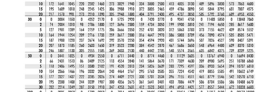
17 PROCEDURE FOR USING THE INDIVIDUAL VENT TABLE To determine the proper size for an individual vent, apply the table as follows: Determine total vent height and length of lateral, based on appliance and vent location and height to top of vent, as indicated in (Table II). If gas appliances, such as a furnace, have not been chosen or installed, estimate height beginning at 6' above the floor. Read down the height column to a height equal to or less than the estimated total height (Table II). Select the horizontal row for the appropriate lateral (L) length. (Table II) 17

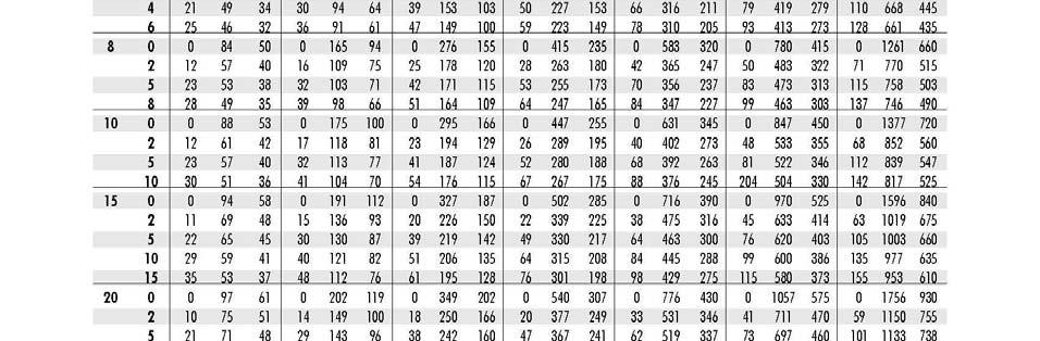
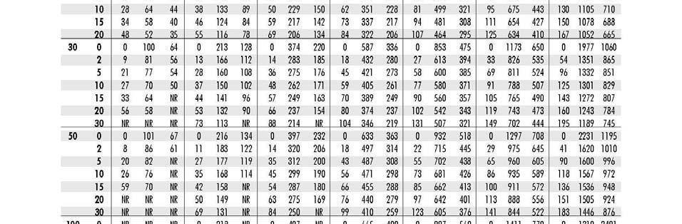

18 Table 2 Individual Vents 18

19 19
20 CONNECTING THE FLUE (COMBUSTION) OUTDOOR INSTALLATIONS AIR FOR COMBUSTION Openings for combustion air must be provided in a panel (door) with direct access to the vestibule area where the burners and draft inducer are located. This air opening must be of sufficient size to provide a suitable supply of air for combustion to the burner compartment, but not less than one (1) square inch free area per every 800 Btu per hour of the specified maximum input rate. The minimum dimension of any air opening should not be less than 3 inches. Heating appliance must be installed so that air access to inlet opening is unobstructed. VENTING The vent termination must be located in accordance with the National Fuel Codes (ANSI Z223.2) in the US or CAN/CGA-B149 Installation code in Canada. The venting system for outdoor units is a Category 1, with vent products at positive pressure and up to 500 F. The cross-section area of the vent duct or pipe must be at least equal to the discharge area of the draft inducer. The discharge opening must always be located in the same pressure zone as the combustion air inlet. For horizontal discharge, the outlet should be located on the same side of the unit as the combustion air inlet. Never locate the vent outlet on the opposite side from the combustion air inlet opening. For horizontal discharge where the flue gases need to be vented vertically, the preferred flue gas discharge should terminate in an exterior flue riser that extends at least to the top of the cabinet and is open at the top and bottom. The riser must be located on the same side of the appliances as the combustion air opening. INDOOR INSTALLATIONS AIR FOR COMBUSTION The furnace must be installed in a location with adequate clearances to provide for an adequate combustion air space, service and inspection, and proper clearance for combustible construction. The furnace shall be located in such a manor that it does not interfere with the circulation of air in the heated space. All fuel burning equipment must be supplied with air that enters into combustion process and is then vented outdoors. Sufficient air must enter the appliances location to replace the air exhausted through the vent system. Do not install appliances in a confirmed space without providing wall opening to and from this space, if building construction is such that the normal infiltration does not provide sufficient air for combustion and venting, outside air must be introduced in accordance with ANSI Z223.1 (Sect and ).Install air openings that provide a total free area in accordance with the following. 20
21 1. Air from inside the building- Opening of a 1 square inch (sq.in) per 1000 Btuh of input, but never less than 100 sq.in. 2. Air from outside (ducted) Opening of 1 sq.in. per 2000 Btuh 3. Air from inside (Direct opening) Opening of 1 sq.in.per 4000 Btuh. 21

22 HEAT EXCHANGER CONDENSATE DRAIN The Heat Exchanger unit is provided with a condensate drain. The 3/8 (PLC w/ Braided S.S.) condensate drain connection is located on the underside of the flue discharge box of the heat exchanger. Both indoor and outdoor units must have the heat exchanger condensate piped to sanitary sewer drain. The drain line shall be installed in accordance with all plumbing codes. When the heat exchanger is located outdoors, the drain must be run inside the provided condensate drain-line chase of the unit, refer to (Figure 10). The chase shall provide piping access to the interior of the building space (preferably a mechanical room or maintenance room), where the condensate tank will be located for easy maintenance and service. All drain lines from the heat exchanger must be protected from freezing. WARNING! Failure to connect the condensate drain can result in uncontrolled condensate drainage into building and/or unit, resulting in standing condensate drainage fluid, which can cause damage to equipment and/or building damage, injury or death. Condensate fluid is high in ph, and is known to corrode and damage, equipment & structure, and may cause other unforeseeable operating problems. WARNING! In areas that experience prolonged below freezing outdoor temperatures, the condensate drain line must be routed through a heated space, as provided with condensate drain chase. Failure to protect the condensate drainage pipes from freezing can result in line freeze, condensate freeze-up in/at unit heat exchanger, causing equipment, building, or other damage, injury, or death. DO NOT DRAIN CONDENSATE ONTO ROOF AREA 22
23 INSTALLATION OF THE CONDENSATE DRAIN / TRAP (Shipped Loose) NOTE: the condensate trap is shipped loose with unit, and requires installation as per plumbing codes before operation of the heat exchanger appliance. DO NOT connect the unit gas lines to heater until all the following instructions have been completed. Before unit is placed on roof curb, ensure there is opening to building space (through provided condensate drain chase in unit and roof curb, refer to (Figure 11). Once the unit has been placed on the curb, locate the condensate collection header (located in the condensate drainage chase area). Connect the plumbing drop lines to the provided stainless steel connection nipple at the Heat Exchanger condensate collection header. Figure 11 Installation of Condensate Trap In an event of an indoor installation, the condensate neutralization tank must be located at a lower point then the unit condensate drainage connection center line. A p-trap must also be installed, refer to (Figure 12). Determine an appropriate location for condensate neutralization tank to be located in either a mechanical or maintenance room & rigidly mount onto wall or appropriate structure. Ensure there is adequate access area around the condensate 23
24 neutralization tank for service & maintenance. Connect the condensate trap to the intake nipple of the condensate neutralization tank. Connect the condensate drop line from the unit s heat exchanger condensate collection header outlet, to the intake end of the condensate neutralization tank. Connect a drainage line to the discharge nipple on the condensate neutralization tank, run drainage line to sanitary sewer connection as per National and Local plumbing codes. Seal all joints and connections with high temperature sealant caulking. Figure 12 P trap Installation CONDENSATE DRAINAGE/NEUTRALIZER INSTALLATION INSTRUCTIONS All plumbing line for condensate drainage from Heat Exchanger appliance MUST adhere to national and local plumbing codes. Extend condensate drain line from unit, through the condensate drainage chase of unit into the building space. (Preferably a maintenance or mechanical equipment area.) Drainage line sizes are to be minimum of ¾ pipe & fitting size. PVC or CPVC pipe material or other suitable for corrosive condensate fluid. The condensate line runs shall be sloped (at minimum of 2%) toward the sanitary floor drain. 24
25 The condensate PVC drain line and fittings shall conform to ASTM D1785 / CSA b137 The condensate CPVC drain line and fittings shall conform to ASTM 2855 / CSA B Use approved methods and material; install all drain lines in accordance with local and National codes. CONDENSATE NEUTRALIZATION TANK INSTALLATION INSTRUCTIONS NOTE - Check with your local water authority for regulations regarding discharge of treated condensate to the drain or sewer system. WARNING! RISK OF DAMAGE TO APPLIANCE! The neutralization kit inlet and discharge must be at a lower elevation than the condensate drain from appliance. WARNING! DO NOT ALLOW EXHAUST FLUE GASSES TO MIGRATE THROUGH THE NEUTRALIZATION TANK. All condensate drains must have a trap to prevent flue gas leakage. Flue gas leakage can cause injury or death from carbon monoxide. WARNING! Connection to the appliance and neutralization kit must be installed to ensure that no condensate backflow into the appliance can occur. The inlet has a center inlet connection port and the outlet connection is off center. Mount the neutralization capsule on the wall or floor securing it with the provided brackets. When mounting capsule in the horizontal position rotate the tube so the outlet is at its lowest point (Figure 10 and 11). The preferred mounting method is in the horizontal position. Connections to the appliance and neutralization kit must be installed to ensure that no condensate backflow can occur. Figure 10 and 11) 25
26 Connect the provided hose or corrosion resistant piping and secure it to the floor or wall to prevent movement. Do not route the condensate line through any area that is exposed to freezing temperatures. If traffic poses a risk, install some protection to prevent movement and/or damage. The Y provided is a safety overflow in the event that the condensate drain becomes clogged. Mount as per installation diagram. Ensure that the condensate will flow freely from the appliance drain into the tank then to the drain. Access to the discharge is necessary for proper maintenance in order to check the effectiveness of the neutralizing media, using ph test strips. If there is no gravity drain available, install a condensate removal pump (by others) designed for use on condensing boilers and furnaces. The condensate pump must be equipped with an over flow switch to prevent the appliance from running should a failure occur. CONDENSATE OPERATION AND MAINTENANCE Operation When the appliance is in operating mode the condensate will flow through the neutralizing media, raising the ph of the condensate to levels that will aid in preventing corrosion of the domestic drain and the public sewer system. Maintenance Monitor the level of the neutralization media in the capsule periodically. Check the ph level at the outlet of the neutralizing kit annually and use a suitable ph test strip paper or an electronic ph meter for precise measurement. The neutralizing media should be replaced when the ph level drops below the minimum level of the local water authority. For replacement media contact your local supplier or factory outlet. RECOMMENDED CONDENSATE NEUTRALIZTION TANK MAINTENANCE SCHEDULE UNIT ph JAN FEB MAR APR MAY JUN JUL AUG SEPT OCT NOV DEC ph ph ph ph ph LIMITED WARRENTY The condensate tank (if provided with unit) is warranted against defects in materials and workmanship for one year. 26
27 ELECTRICAL CONNECTIONS When installed, the appliance must be electrically grounded in accordance with local codes, or in the absence of local codes, with the National Electrical Code, ANSI/NFPA, and/or the Canadian Electrical Code, CSA C22.1, if an external source is utilized. Control voltage is as indicted on the rating plate. Follow the wiring diagram supplied with the unit, (NOTE: when submittal wiring diagrams are provided, the submittal diagrams shall only be used for equipment wiring reference.) If a space thermostat is used with the furnace, locate the thermostat so the cold drafts and hot discharge air streams do not affect the performance of the unit. Do no mount the thermostat on the casing of the unit, as it will be affected by radiated and conducted heat. Refer to the instruction furnished with the thermostat for further details. If any of the original wires as supplied with the unit must be replaced, it must be replaced with type TEW 105 degrees or its equivalent except where noted. Temperature controllers, limit controllers, remote selector switches, door switches or any other auxiliary electrical items must be connected to the terminals provided as shown on the wiring diagram. For units shipped in multiple sections, electrical connections between sections are to be made by the installer in the field. Field wiring to be done by the installer is denoted by dotted lines on the wiring diagram. Solid lines on the wiring diagram indicate factory wiring by the manufacturer. The unit must be electrically grounded in accordance with local codes, or in the absence of local codes, with the National Electrical Code, ANSI/NFPA 70, and/or the CSA.C22.1 Canadian Electrical code. NOTE: Due to the nature of transport, installer shall check all contacts and termination points for tightness, and or loose wires. 27
28 Figure 13 Standard Wiring Diagram 1 28
29 Figure 14 Standard Wiring Diagram 2 29
30 Figure 15 Standard Wiring Diagram 3 30
31 GAS PIPING All gas piping should be in accordance with NFPA, National Gas Code, and CAN 1- B149 with the regulation of local authorities having jurisdiction. An emergency manual shut down valve shall be provided upstream of the piping to unit and should be labeled for quick identification. Color coding of gas piping is also recommended. The appliance and the appliances individual shut off valve MUST be disconnected from supply gas piping system during any pressure testing of the supply gas line system when pressures are in excess of ½ p.s.i. [3.5 kpa]. The appliance must be isolated from gas supply piping system by closing its individual manual shut-off valve during any pressure testing of the gas supply piping system at pressures less than or equal to ½ p.s.i. [3.5 kpa]. Carefully check the unit rating plate for fuel type and supply pressure. If required, locate the high-pressure regulator at least five feet from the unit. Gas lines must not be located in such a way as to hinder access to the unit. A minimum 1/8" NPT tapping plug, accessible for testing gauge connection, must be installed immediately upstream of the gas supply connection to the appliance. Check for gas leaks with soap and water solution. Never use open flame to check for gas leaks. The appliance and its individual shut-off valve must be disconnected from the gas supply piping system during any pressure testing of that system at test pressures of ½ psi (3.5 kpa). The appliance must be isolated from the gas supply system by closing its individual manual shut-off valve during any pressure testing of the gas supply piping system at test pressures equal to or less than ½ psi (3.5 kpa GAS PIPING/REGULATOR VENTING High gas pressure regulator (if required), low pressure regulator, pilot pressure regulator, gas pressure switch (if supplied), and normally open vent valve (if supplied) must be vented outside of building for an indoor unit (check with authorities having jurisdiction). 31
32 NATURAL GAS AND PROPANE INSTALLATION: Installation must be made in accordance with the requirements of the authorities having jurisdiction in the area. Check the unit rating plate and confirm fuel type, supply pressure, input rating, and temperature rise. Refer to the heater rating plate for determining the minimum gas supply pressure for obtaining the maximum gas capacity for which this heater is specified Gas supply pressure higher than the unit rating plate requires an additional field supplied gas regulator. Install an approved shutoff valve on the gas supply in accordance with the requirements of the authorities having jurisdiction. Manufactures specification states a minimum of 3ft from the gas connection (union). Gas lines shall not interfere with unit access. The gas line connection at the heater shall have an approved drip leg with screwed cap. A minimum 1/8 inch NPT plugged tapping, accessible for test gauge connection, must be installed immediately upstream of the gas supply connection to the unit. On indoor units any control device (regulator, diaphragm valve, high and low pressure switch, etc.) that requires a bleed or vent line, must be vented in accordance with applicable codes. To obtain specific temperature rise settings, Temperature rise is directly affected by the air flow across the heat exchanger. The unit shall be air balanced (by an approved air balancing contractor) as to provide specified air flow. (see Figures 16 through 20) TEMPERATURE RISE AIR FLOW TABLES Table 3 HTDM 200 Air Flow MODEL INPUT/OUTPUT MBH Inlet Pressure Natural Gas WC Inlet Pressure Propane WC AIR CAPACITY CFM TEMPERATURE RISE (Deg-F) HTDM plus OMEGA 200/
33 Table 4 HTDM 400 Air Flow MODEL INPUT/OUTPUT MBH Inlet Pressure Natural Gas WC Inlet Pressure Propane WC AIR CAPACITY CFM TEMPERATURE RISE (Deg-F) HTDM plus OMEGA 400/ Table 5 HTDM 600 Air Flow MODEL INPUT/OUTPUT MBH Inlet Pressure Natural Gas WC Inlet Pressure Propane WC AIR CAPACITY CFM TEMPERATURE RISE (Deg-F) HTDM plus OMEGA 600/
34 Table 6 HTDM 1000 Air Flow MODEL INPUT/OUTPUT MBH Inlet Pressure Natural Gas WC Inlet Pressure Propane WC AIR CAPACITY CFM TEMPERATURE RISE (Deg-F) HTDM plus OMEGA 1000/ Table 7 HTDM 1500 Air Flow MODEL INPUT/OUTPUT MBH Inlet Pressure Natural Gas WC Inlet Pressure Propane WC AIR CAPACITY CFM TEMPERATURE RISE (Deg-F) HTDM plus OMEGA 1500/
35 NOTE: AIR-FLOW REQUIEMENTS MAY DIFFER FROM ABOVE BASE CHARTS. FOR SPECIFIC AIR FLOW AND TEMPERATURE RISE REFER TO EQUIPMENT SUBMITTAL PACKAGE, OR CONSULT FACTORY. HEAT TRANSFER FLUIDS The coil(s) (when provided) have been selected for use with a specific heat transfer fluid as shown on the Submittal Record. Use of other fluids will result in different performance and can damage the coil(s). It is imperative to properly select and apply heat transfer fluids used in heating and cooling systems. Untreated, improperly treated or improper use of fluids or use of fluids not approved for use in commercial heating and cooling systems can damage coils and system components. For selection and application of heat transfer fluids, always follow the manufacturers recommendations including treatment, mixing and filling. Warranty will be void if coil damage results from misapplication or improper treatment of the heat transfer fluid. Some systems may use CPVC piping. Do not use propylene glycol with CPVC. COOLING COILS Cooling coils (when provided) are installed in the air stream, condensation will form on coil surface and provisions must be made to properly dispose of condensate liquid. Condensate drains are located on the exterior of the unit (See Submittal Package for Details). The condensate should be disposed of according to local or national plumbing codes. 35
36 GENERAL OPERATING INSTRUCTION 1) Refer to the rating plate for fuel input and supply pressures. 2) Do not attempt to start the burner if the unit is full of vapor or gas, or if the combustion chamber is very hot. 3) Do not leave combustible material near the unit. 4) Shut off the manual fuel supply valve if the burner has been shut down for an extended period of time. 5) Do not start unit unless all the access doors are securely in place. 6) Refer to literature regarding controls, gas valves and other components. START-UP PROCEDURES PRE CHECKS 1. Ensure the main disconnect switch is in the off position. 2. Ensure the burner on-off switch is in the off position. 3. Check all electrical and gas connections and tighten if necessary 4. Check main rating plate voltage against the supplied voltage to disconnect. 5. Check main blower by rotating blower shaft by hand to ensure it is free to turn. 6. Tighten bearing set screws, and pulley set screws. 7. Remove shipping blocks from vibration isolators (if equipped) 8. Check for loose items shipped inside blower section (if supplied) and remove. 9. Check heater outlets for obstruction. 10. Check all fuse blocks to determine that correct fusing is installed. 11. Check the supply fan motor thermal overload setting against the rating plate value. 12. Check building system gas supplies and be sure all lines are purged of air, 13. Check building system gas supply pressure. 36
37 CAUTION GAS UNITS At maximum input the gas pressure must fall within the range specified on the unit rating plate. Optional high and low gas pressure switched (if supplied) must be reset. 14. Check all piping for tightness and correct any signs of leaks. WARNING Fire or explosion hazard can cause property damage, severe injury, or death. Check for gas leaks with rich soap and water solution any time work is done on a gas line. Never use an open flame to detect gas leaks. START-UP 1) Turn on power to the unit. 2) Enable the unit (Fan Only) 3) Ensure supply blower rotation is correct. 4) Check supply blower motor amps against rating plate values. If actual figure is significantly different that the rating plate value, take corrective actions with respect to duct work and accessories external to the unit 5) Set thermal overloads to appropriate motor performance after all adjustments have been made. 6) Enable burner. 7) Verify unit s sequence of operation corresponds to sequence provided in the supplied literature. 8) Refer to start-up check list and field report for settings that are to be checked on the unit. Note: Factory set pre purged timer is set to 65 seconds. 37
38 9) Combustion analysis must be completed, to ensure proper operation of heat exchanger. 10) Disable burner. Ensure the burner shuts down as per the sequence of operation. 11) Disable unit. Ensure the unit shuts down as per the sequence of operation. SHUT DOWN 1. EMERGENCY SHUT DOWN a) Set disconnect switch to "off' position. b) Close the manual main fuel valve. c) Set the unit controls to the off position. 2. SERVICE SHUT DOWN a) Set the unit controls to the off position. b) Close the manual main fuel valve. MAINTENANCE Regular maintenance is necessary to ensure the efficient operation and long life of this unit. This maintenance should be performed by or supervised by qualified service personnel. A maintenance schedule should be prepared for the unit based on its application and location. 1. For checking gas leak tightness of safety, use a rich soap and water solution and spray/apply on the points of connection. 2. Turn shut off valve on and wait, if air bubbles form, turn shut off valve closed. 3. Repeat steps 1 and 2 until no more air bubbles form. Note: It is important to check at least an annual basis. 38
39 RECOMMENDED QUARTERLY MAINTENANCE WARNING Fire or explosion hazard can cause property damage, severe injury, or death. Check for gas leaks with rich soap and water solution any time work is done on a gas line. Never use an open flame to detect gas leaks. 1) Replace air filters if necessary. Replace filters only with type equivalent to those supplied with the unit by the factory. Location of filter access panels are marked on the unit. To replace filters, remove service panel or open blower door, slide out dirty filters and replace with same size filters in order to prevent possibility of dust collecting inside of unit. Filter sizes are written on the filters and rating plate. For a complete list of filters sizes, contact manufacturer. 2) Inspect blower wheels and housing, clean if necessary. 3) Check for loose connections in the wiring. 4) Check the voltage at the unit while it is in operation. 5) Inspect all contactor to ensure that they are clean and making good contact. 6) Check all belts. Adjust or replace as necessary. 7) Check motor amperage draws against rating plate values. 8) Check all bearings and lubricate if necessary. 9) Check all dampers, linkages and damper actuators; adjust and tighten as required. 10) Inspect combustion fan assembly for wear, 11) Inspect combustion blower wheel for cleanliness. 39
40 12) Check the fuel supply pressure to the unit. 13) Check operation of all safety controls. 14) Check the flame sensor signal. 15) Check the manifold pressure. RECOMMENDED YEARLY MAINTENANCE WARNING Fire or explosion hazard can cause property damage, severe injury, or death. Check for gas leaks with rich soap ans water solution any time work is done on a gas line. Never use an open flame to detect gas leaks. 1) Perform the recommended quarterly maintenance. 2) Check Flame Sensor and Igniter. a. Remove attached wires; be sure to note the terminals so as to ensure proper reassembly. b. Remove flame sensor and igniter from the burner assembly, using appropriate tools. c. Visually inspect the flame sensor and igniter for cracks in the porcelain, warping of the rods, or corrosion build up. If these parts show any ware it s the manufacture recommendation to replace this device(s). 3) Complete a combustion analysis report, to ensure proper operation of heat exchanger. 4) Ensure the unit shuts down as per the sequence of operation. 40
41 5) Inspect Burner assembly, clean & service if required. 6) Ensure gas has been turned off to the unit and a site specific lock out procedure is in place. 7) Remove flame sensor and igniter 8) Remove gas line connection at burner assembly. 9) Remove the combustion fan. 10) Remove all fastening bolts from the burner box and keep at hand for re-use. 11) Remove burner box from unit. 12) Remove all old gasket material from burner box flanges, and attachment flanges. 13) Inspect burner and burner orifices for residue, debris or corrosion. Note: Orifices shall be cleaned with an approved orifice cleaning tool. (DO NOT DRILL, REEM, OR ALTER THE ORIFICES IN ANY WAY.) 14) Ensure no debris from cleaning process is left inside the burner box. 15) Re-install the burner box. Install a new burner box gasket. Ensue all mounting bolts are in place. Use high temperature silicone to seal the burner to the mounting flanges. 16) Re-install combustion fan. Install a new gasket. Ensue all mounting bolts are in place. 17) Re-install flame rod and igniter. 41
42 HTDM 90+ Omega Series Installation, Operation, Maintenance Manual WARNING Failure to replace all fasteners, seals, or removed components may result in serious injury, death, and/or severe equipment damage. 18) Redo combustion analysis report and compare to previous one, to ensure proper operation of heat exchanger. 19) Inspect and clean the condensate collection and disposal systems to ensure proper drainage. 20) Ensure the unit shuts down as per the sequence of operation. 42

43 HTDM 90+ Omega Series Installation, Operation, Maintenance Manual 43
44 HTDM 90+ Omega Series Installation, Operation, Maintenance Manual NORMAL START-UP SEQUENCE 1) Call For Heat The ICECON controller will indicate power by illuminating the power LED (light emitting diode). The combustion blower is ramped to full speed. Upon proof of closer of the modulating gas valve the auto heating light is energized. 24VAC power is sent to the purge timer coil. Upon the timing out of the purge timer the combustion blower will ramp to minimum speed for trial for ignition. 2) Trial for Ignition Upon timing out the combustion blower drops to low speed and the ignition controller is powered. The pilot line solenoid is powered opening the pilot gas flow to the burner. Simultaneously the ignition controller initiates spark. Upon proof of flame ignition controller opens the main gas valves allowing gas to flow to the modulating gas valve, simultaneously sending a 24VAC signal to the ICECON2 controller. Upon receiving the 24VAC signal the board will enter System Preheat. 3) System Preheat System preheat is indicated by a flashing Heat Mode LED. During this stage the ICECON controller will ramp the firing valve and combustion blower to midrange without energizing the main supply fan. Preheat lasts approximately 60 seconds. Upon completion of the system pre-heat the main supply fan energizes and the unit will begin to operate in one of the following modulation modes HEAT MODES 1) Factory Set Discharge Temperature, no field adjustment. The unit will adjust the firing rate to maintain the factory set discharge temperate. The Power, Heat Mode and Auto LEDs are illuminated to indicate this condition. 2) RTS (Remote Temperature Selector) There are two temperature ranges for the RTS, 40-90F and F. The unit will modulate to maintain the temperature selected on the RTS. 44
45 3) External Modulation Control The ICECON controller is capable of responding to a 0-10Vdc or 4-20mA signals. To configure the ICECON controller to respond to an external signal the RSP and Mod/std check boxes (In the software interface) must not be checked. The control signal connects to terminals J3-25 and J3-26. The ICECON controller will remain in control of errors and will lock out if any error condition occurs. The BMS has complete control over the discharge temperature. The BMS supplier must supply the ICECON controller with either 0-10 VDC or 4-20 ma signal. The signal is to be supplied to terminals J25 and J26. After normal startup sequence is finished the auto led will remain de-energized. The unit will now only respond to the BMS signal and is unable to self adjust to changes in conditions. The ICECON controller will respond to the incoming signals and modulate to a corresponding firing rate. The firing curve is composed of discrete steps. Each step is controlled by a trigger voltage or current that once reached the combustion will move to the next combustion step. When tuning a BMS system the following points must be considered: How ICECON Controller Responds to External Modulation Control The ICECON controller automatically scales the incoming signal to the internal combustion curve that has been programmed at the factory. The curve is made of discrete steps. There are dead- bands in the signal in which the unit will not modulate with an increase or decrease in the control signal. Once a signal is received the controller will modulate to the corresponding firing point. During this transition the ICECON controller will not respond to changes in the control signal. As a result the Control system must be tuned for a very slow response. Poor temperature control will result if the system is not tuned correctly. Switching From ma control signal to VDC Remove the ICECON control cover plate. In the lower right hand area of the circuit board there is a small black jumper labeled 4-20mA enable. This jumper is left in place when receiving a 4-10 ma signal and is removed when using a 0-10 Vdc signal. 45
46 AVAILABLE OPTIONS (Software controlled) 1) Space Override Units equipped with this option will modulate normally in one of the above heat modes until continuity is sensed between terminals J19 and J21. Upon sensing continuity unit will de- energize the auto indicator LED and ramp to full fire until the contacts are opened. Regular heat mode operation will be resumed once the contacts between J19 and J21 are opened. 2) Low Limit The unit will shut down the supply fan if the duct temperature falls below the factory set point. 3) System Preheat The unit can use a built in time delay before the contacts to the main supply fan are energized. This will allow a preheating of the heat exchanger to insure that only warm air will be supplied to the space. Preheat operation begins with a normal trial for ignition. Once flame has proven the unit will modulate to the midpoint of the firing range. The heat mode led will indicate the preheat cycle by flashing. The unit will remain at the midpoint until the preheat cycle is ended. Once ended the main supply fan contacts will energize and normal heat mode operation will begin. 4) Standby mode Standby mode is to be used in conjunction with an on/off thermostat or when periodic heating is required. In Standby mode the ICECON is continually powered. The unit will indicate standby mode by flashing the power LED. In this mode the heat cycle will remain powered down until there is a call for heat from indicated by a 24VAC signal on terminal J22. Upon a call for heat a normal start up sequence is ran and the unit will then enter heat mode. Once the call for heat is satisfied and the 24VAC signal is lost on terminal J22 the ICECON controller will exit heat. The unit will enter a post heat purge. During this time the combustion blower and firing valve are ramped to full fire. Upon completion of the post heat purge the burner and combustion blower are shut down. The main supply fan will remain in operation for a period of time to allow for cooling of the heat exchanger. 5) Fan on in Standby Mode With this option the main supply fan will remain in operation regardless of the call for heat when the Standby option is selected. During transition between heat and standby operation the supply fan may cycle on and off for a short duration. 46
47 HTDM 90+ Omega Series Installation, Operation, Maintenance Manual ERROR SIGNALS 1) High Limit Error This condition will occur when the ICECON controller has a duct temperature greater than the factory set point or the discharge sensor contacts are in the open condition. This condition is indicated by the illumination of LED numbers 5 and 8. The unit will indicate the high limit error and will lock until reset. Led numbers 5 and 8 will illuminate. The main supply blower will remain energized until the duct temperature falls below the factory set safe shut down temperature. The combustion blower will remain at max RPM until the unit is reset. 2) Low Limit Error The low limit lock out condition occurs when the air temperature in the duct work has fallen below a factory set position. This condition is indicated by the illumination of LED numbers 5, 6 and 7. Upon a drop in duct air temperature the unit will lock out and shut down the burner. The main supply fan will be de-energized to stop the flow of unheated air form entering the space. The combustion blower will run at the max RPM setting. 3) Air Proving Error Air proving error occurs when the tachometer stops sending a signal to the ICECON controller. This condition is indicated by the illumination of LED numbers 5 and 6. The fan operation must be checked as well as the function of the tachometer sensor itself. Improper operation will cause poor and irregular combustion. The unit must be reset to reinitiate. 4) Flame Error Flame error occurs when the flame signal is lost to the ICECON controller. Lock occurs after the fourth attempt during trial for ignition and in any instance in which flame is lost after heat mode has been achieved. The unit must be reset to reinitiate. 5) Valve Error Valve error occurs when the ICECON controller looses communication with the modulating gas valve or abnormal operation of the modulating gas valve has been detected. This condition is indicated by the illumination of LED numbers 5, 6 and 8. The unit will lock out and will require resetting to reinitiate. 47
48 Trouble Shooting AIR PROVING ERROR FLAME ERROR HIGH LIMIT ERROR LOW LIMIT ERROR VALVE ERROR The ICECON controller has lost the Tachometer signal. Check combustion blower operation. Check tachometer sensor operation (see section ******). Check ICECON fuses The ICECON controller has lost the 24 VAC on terminal J22. Check gas supply Check ignition module for proper operation Check all fail safes for proper operation Check valves, manual and solenoid, for proper operation Check ICECON fuses The ICECON controller has received a temperature reading above the factory set value. Check main blower and dampers for proper operation. Check discharge sensor for correct attachment. Open contacts on the Discharge sensor terminals will cause indication of a high limit condition. Check ICECON fuses The ICECON controller has detected a temperature below that set by the as the low limit. Check unit for proper operation. Check discharge sensor. Continuity between the white and black terminals will return a 51 degree F signal. Check ICECON fuses The ICECON controller has 48
49 lost communication with the modulating gas valve. Check that valve is powered and operating correctly. Check for signal (0-10VDC) on terminal J11. The unit will not fire until valve has proven closed (<=2.0 VDC signal on terminal J11) Check ICECON fuses NO DISPLAY ON ICECON2 CONTROLER BOARD WILL NOT ENTER HEAT MODE UNIT WILL NOT MODULATE SUPPLY FAN DOES NOT INGAGE Board requires 24VAC on terminal J2 for operation. Check fuses on both the control panel and Circuit board and replace as necessary. Verify correct wiring, wiring connections and grounding of the electrical components. ICECON requires 24VAC on terminal J12 to enter heat mode. Board requires a 2.0 VDC signal on terminal J11 before initiating trial for ignition. Flame has not proven. (ICECON) requires a 24VAC signal on terminal J22 before entering heat mode. The controller will use 4 trials for ignition before indicating flame error. Check for free rotation of the modulating valve Check for correct feedback signal Check for power on terminal J5 on the ICECON controller. If power is trace unit wiring as per diagram to determine fault. Check for power on terminal J6. If power is not present trace wiring as per diagram to determine fault. If power is present on J6 but not J5 the system is not calling for the supply air. 49
50 Tachometer Test Procedure Disconnect power to the combustion blower. Engage a heat cycle so that the board locks out on an air proving error. Verify approximately 5 VDC between terminals J2-17 and J2-18. If voltage is not present disconnect all tachometer leads from the board and recheck. If power is now present replace the tachometer and verify wiring is correct. If power is still absent replace the ICECON controller and verify wiring. Ensure that the magnet is not aligned with the end of the tachometer. Approximately 5Vdc should be between J2-18 and J2-16. Rotate the combustion blower wheel until the magnet is aligned with the tachometer. The voltage between J2-18 and J2-16 should now be zero. If this is not the case check the distance from the tachometer and the magnet. This space should not exceed 1/8 th of an inch. If required adjust to the correct pacing. If the systems remain the same the magnet will have to be remove and reversed as the tachometer is polarity sensitive. Discharge Sensor and RSP (Remote Set Point) Test Once the combustion curve has been set up and the board configured for stand alone the operation of the discharge sensor and RSP must be verified. To accomplish this the computer must be connected to an active ICECON controller. With the system in heat mode activate the Tools pull down menu and select I/O view. A new screen is no displayed. On the lower right there are three buttons, Read, 5 second read and Exit. Read performs a one-time read of the variables. 5 second read performs a read function every 5 seconds. Exit closes the I/O screen. Click the 5 second read button. Compare the value of the discharge sensor reading with a known temperature. At this time if a discharge reading of 281 F is displayed there is an open circuit in the discharge sensor circuit and the unit will lock out on High Limit Error. The discharge sensor reading should be stable with less than 1-2 fluctuations at steady state conditions. Turn the RSP counter clockwise until the physical stop is reached. A value of 40 when a F RSP is being used and 90 when a F RSP is used should be displayed in the RSP value (This may take up to 30 seconds). Turn RSP clockwise until the physical stop is reached. The upper limit of the RSP should be displayed. Verify a mid point and align the pot to the correct temperature scale position. To do this, use a small screwdriver to loosen the knob and reposition such that the arrow points to the correct temperature. Retighten the knob. The low temperature scale should have an ohm range of Ω resistance range. The High temperature range RSP should have 100kΩ-200kΩ resistance range. 50
51 HTDM 90+ Omega Series Wiring Installation, Operation, Maintenance Manual J1 J2 J3 J4 J5 24 VAC Neutral 24 VAC Normally opened contact to purge timer coil 24VAC for purge timer common Normally opened contact to supply fan J6 24VAC for supply fan common J7 Solid state relay (+ VDC) J8 Solid state relay (- VDC) J9 Modulating gas valve control signal(2-10 VDC) J10 Modulating gas valve ground (24VAC common) J11 Modulating gas valve feedback signal (2-10 VDC) J12 Heat mode/ Standby (Switched 24VAC) J13 Temperature Sensor Ground (-VDC) J14 Temperature Sensor Supply (+ 5VDC) J15 Temperature Sensor Signal (+VDC) J16 Tachometer Sensor Signal (+VDC) J17 Tachometer Sensor Supply (+ 5VDC) J18 Tachometer Sensor Ground (-VDC) J19 Space override contact J20 System Ground J21 Space override contact J22 Flame detect in (24VAC) J23 Remote temperature selector contact J24 Remote temperature selector contact J25 Building management in J26 Building management in 51
52 HTDM 90+ Omega Series Programming the HTDM ICECON controller Installation, Operation, Maintenance Manual To correctly configure the ICECON series of controllers the ICECON software must be used to communicate with the controller. Factory training is required. Changes to the control program can cause poor combustion, improper or undesired operation. Software identification For the ICECON controllers the icecon1.7b version of the software must be used. This software can be identified by the seven configuration check boxes in the top right hand corner of the main screen. The original software only had 3 configuration boxes. Setting up the Software To establish communication ensure that the ICECON controller is in either Stand-By mode (indicated by flashing power led), in Heat Mode (indicated by both Power and Heat Mode leds illuminated) or locked in an error condition When first installed the program will not be configure to your system. To properly configure the software you must chose the correct COM port for the serial cable connection on your computer. To begin activate the Settings pull down menu and select ComPort. Select the COM port if known. If the COM port configuration on you computer is not known you must connect to an active ICECON controller. Once this is accomplished activate the Settings pull down menu and select ComPort. Begin by selecting the initial COM port COM 1. Allow seconds for the software to communicate. If the board continues to indicate Board not communicating then try another COM port. If communication cannot be established ensure that only one application of the ICECON software is running. Check that the correct communication cable is being used (9-pin, straight through cable with gender changer) and is connected to both the computer and ICECON controller. Once configured the software will store the correct COM port. This procedure will only be necessary upon initial installation of the software. 52
53 HTDM 90+ Omega Series Installation, Operation, Maintenance Manual The Main Interface This screen provides a view of the current settings contained in the ICECON controller.various control values such as the high and low limits can be adjusted in this environment. The options that the controller is currently configured with are displayed in the upper right corner and are indicated by a check mark in the corresponding box. The combustion curve settings, six in total, located at the bottom of the screen cannot be adjusted in this environment. Figure 16 ICECON Interface Kp and Ki are factory set control values that effect the system response time and accuracy. Check boxes control which factory set options have been selected and programmed. Changing these will effect the required inputs and outputs of the unit. Factory Set Discharge Temperature Factory Set High Limit Factory Set Safe Shut Down Factory Set Low Limit Displays all six combustion points from which the firing curve is calculated. Displays the corresponding RPM value for each point of the combustion curve. 53

54 HTDM 90+ Omega Series Installation, Operation, Maintenance Manual System Tune Interface To access the combustion settings activate the tools pull down menu and select the system tune option. The screen displayed in figure 2 is now visible. Adjustments to the combustion curve can be made to any of the six points. The previous screen will not be updated until the user has left system tune mode. Figure 17 System Tune Interface The Fan box allows the adjustment of the combustion blower set point at one of the 6 set points. By adjusting this value up or down the fan speed can be increased or decreased. Each point must increase in value or the system will lock out in set up error. The valve box allows for the adjustment of the valve/gas flow at the set point in question. The value indicated in this box will be the output voltage to the modulating gas valve. When highlighted this will proceed to the previous point. When selected the program will move to the next point. Sends displayed values to the ICECON controller. 54

55 HTDM 90+ Omega Series Installation, Operation, Maintenance Manual I/O View The I/O view option located in the tools menu is used as a real time diagnostic tool. The system will communicate a provide status of system safeties and operating points. Figure 18 Diagnostics Interface Air proving and flame detect provide information on the combustion blower and flame signal. ON indicates normal operation while OFF will confirm a loss of signal. The bottom four values display the current values of fan speed, valve voltage, discharge temperature and RSP. The bottom four values display the current values of fan speed, valve voltage, discharge temperature and RSP. The READ option will do a one time real time read of the system operation at that time. 5 SEC READ will perform a real time read every five seconds after it is initiated. ICECON III Configuration The main configuration for the board is contained in the seven check boxes located in the top right corner of the main screen. 1. ByPass System Preheat Once checked the preheat cycle will be eliminated. The preheat cycle will take place once main flame has been established. The burner will be ramped to a mid point in the firing range and remain there for approximately 45 seconds. Once complete the output on J1-5(usually used to energize the supply fan) will be energized. The ICECON controller is now ready for modulation. 2. RSP Once checked the ICECON II controller will look for a remote temperature dial for the temperature set point. The remote temperature dials are available in two ranges F and F. This is only used during standalone operation and cannot be used when a building management system (BMS) or other source is being used to provide the modulation control. When not checked the ICECON II controller will maintain the temperature indicated in the Discharge Temperature set point box. 3. Mod/std. This when checked activates the internal modulation control routines. When checked the system will not respond to a BMS signal. 55
56 HTDM 90+ Omega Series Installation, Operation, Maintenance Manual 4. Space Override When checked the ICECON controller will monitor terminals J3-20 and J3-21 for continuity. When continuity is detected the system will ramp to full fire and remain at this point, regardless of discharge temperature, until continuity is lost. 5. Standby Mode When checked the ICECON controller will operate in both heating and non-heating modes. To enter a heating cycle 24 VAC must be present on terminal J2-12. When not checked board is only to be power during a heating cycle. 6. System Fan on in Standby Once checked the output on J1-5 will be energized in both Standby and Heat modes. A delay will be experienced during transitions between the two modes. 7. Low Limit When checked the low limit sensing routines are energized. During Heat Mode if a temperature is sensed below the low limit set point the J1-5 output will be deenergized. There is a non-adjustable 3-minute delay upon initiation of a heat cycle. Set Points Located beneath the ICECON logo are six set points. They are as follows: 1. Discharge Temperature. This box is used to introduce a positive offset from the RSP set point. It is used for calibration of the discharge sensor and in the event that no RSP is being used will indicate the temperature to be maintained. 2. Upper Limit.This temperature is the set point at which the ICECON controller will deenergize J1-3 (Burner on output) to shut off the heat when the discharge sensor detect any temperature above this value. Once this has occurred the unit will indicate High Limit Error. 3. Safe Shut Down.Upon tripping on a High Limit Error J1-5 (Supply fan output) will remain energized until the discharge sensor detects a temperature below this set point. 4. Kp. This is used for controlling the aggressiveness of the temperature response. The higher this value the faster the response and greater chance of temperature overshot. The default value is Ki. This is used to control the temperature response and is an error multiplication factor. The default is 2. 56
57 HTDM 90+ Omega Series Installation, Operation, Maintenance Manual 6. Low Limit. When a temperature below this set point is detected, after a 3-minute interval time delay, the ICECON controller will de-energize J1-5 and J1-3 and lock out on Low Limit Error. Combustion Set Points Located across the bottom of the main screen of the ICECON application are the six combustion set points. Each point has three parameters that describe each point. The Fan box contains a number that controls the cycle time of the solid-state relay and trial control signal. This number will determine the speed at which the combustion fan will rotate when firing at the corresponding firing point. The fan rotation speed is indicated by the RPM box. This value is read in from the tachometer sensor as the combustion points are configured. This value is used by the software as a reference to ensure that the correct fan speed is maintained. Once configured the RPM values must maintain a 200-rpm separation between points and increase as you move from left to right across the screen. The Valve box contains the valve set points. This will represent actual DC voltage being sent to the modulating gas valve. These points must increase as you transition from left to right across the main screen. The valve functioning range is 2 to 10 VDC. Altering Combustion Set Points Calibrating the Tachometer Before altering any points the main firing valve should be switched to the closed position. When adjusting combustion points it is possible to override the internal stepping functions. To begin setting up the combustion curve access the Tools pull down menu and select the System tune function. This gives direct access to the combustion curve set points. The first point (low fire) is displayed. To override the system and force the system to low fire press the Send button. The combustion fan will adjust to the appropriate speed and the modulation gas valve will track to the correct voltage. It is important to notice that the valve voltage does not correspond to the voltage that was displayed on the main screen, it is in fact double. This is just how it is at this time so live with it. When the main screen is displayed the actual voltage to being sent the valve is displayed (1/2 system tune voltage). Once the valve has reached the low fire set point allow 10 seconds for sufficient sampling time of the fan speed. Click the Next button and the system will now display the second combustion point. Press Send to drive the system to this combustion point. Allow the actuator to travel and stop at the correct voltage. Allow 10 seconds to achieve an accurate rpm reading. Repeat the process until the high fire set point is reached. Press Exit to return to the main screen. After a few second the system will update the combustion points and the updated tachometer readings will be displayed. 57
58 HTDM 90+ Omega Series Installation, Operation, Maintenance Manual Adjusting Combustion Points The following tachometer and valve set points provide a rough guideline. Point #1: rpm, 2.5Vdc (5.0Vdc in system tune) Point #2: rpm, 3.5Vdc (7.0Vdc in system tune) Point #3: rpm, 4.5Vdc (9.0Vdc in system tune) Point #4: rpm, 5.5Vdc (11.0Vdc in system tune) Point #5: rpm, 6.5Vdc (13.0Vdc in system tune) Point #6: rpm, 8.0Vdc (16.0Vdc in system tune) It is very critical to maintain a minimum 200rpm separation between combustion points. Once this rough curve has been established override this system to high fire. Open the firing valve and set the manifold pressure. Shut the firing valve and force the system to low fire. Reopen the firing valve when the system is at low fire. Walk the system through each point in the combustion curve and check combustion making adjustments to the gas valve voltage as necessary. Once complete exit system tune and recheck complete curve. If the curve is satisfactory press the Write button. Confirm that the program has been updated by clicking the Read button. High fire should be running between 5-7% oxygen, 7-9% CO2 while at low fire that number will vary from 18-20% oxygen, 0.1-1% CO2. Remember as the dirt accumulates the combustion fan performance will drop off so allow excess oxygen during initial factory set up. Saving a ICECON Program Once a HTDM has been configured and all the combustion points have been set (these will vary from unit to unit) it is time to save an electronic copy. Activate the file pull down and click Save as. A new screen will pop up displaying the directory in which the file will be saved, the type of file being saved (*.ice..don t change this) and the name of the file to be saved. Change the name of the file to something meaningful (job number for example). Click the save button and the file has been saved. This should be done whenever working on a unit that has been in operation and should be used as a base line for adjustments. Uploading a ICECON File to a Controller Connect the computer to the ICECON controller and establish communication. At this time the program that has been stored in the controller will be displayed. To load an existing program open the File pull down menu and click the Open function. Locate the file to be loaded and select it. At this time the program to be loaded is displayed on the ICECON interface screen. To upload this to the board click the Write button. This will overwrite the information stored with the program displayed on the interface. To confirm that the information has been uploaded press the Read button and the stored information will be displayed. Some programs may not be compatible and will cause the Board not communicating to be displayed. Try an alternate program. 58

59 HTDM 90+ Omega Series Error Codes of the ICECON Controller Installation, Operation, Maintenance Manual 1. High Limit Error. The high limit error will occur when the discharge sensor detects a temperature above the upper limit set point. A false high limit trip can occur when the discharge sensor in not connected, as an open circuit in will default the temperature reading to 281 F. This is characterized by the system entering heat cycle, purging, lighting and approximately 5 seconds after main flame has proven, locking out on high limit. 2. Low Limit Error. This occurs when the discharge sensor detects a temperature below the low limit set point. A false reading can be created if there is continuity (i.e. a dead short) between terminals J2-13 and J2-15. In this case the board will be receiving and false temperature reading of - 58 F. 3. Valve Error. This will occur if the ICECON controller loses communication with the ball valve. To operate the controller must receive the feedback signal form the ball vale whenever the ICECON III controller is powered. 4. Air Proving Error. If the signal from the tachometer is lost the board will lock out on this condition. To check for proper operation of the tachometer perform the Tachometer test located in the following section. 5. Flame Detect Error. If the ICECON controller has not detected a flame (i.e. receiver a 24Vac signals on terminal J3-22). 6. Setup Error. This error occurs when the Combustion points have been incorrectly configured. Figure 19 ICECON Controller 59
HTDM 80+ OMEGA Series
 HTDM 80+ OMEGA Series Installation, Operation, Maintenance Manual Models: 1500 ATTENTION: Read this manual, unit submittal sheets and all labels attached to the unit carefully before attempting to install,
HTDM 80+ OMEGA Series
 ICE WESTERN SALES LTD. 9765 54 Street SE Calgary, AB T2C 5J6 Phone: (403) 252-5577 Fax: (403) 252-5556 HTDM 80+ OMEGA Series Installation, Operation, Maintenance Manual Models: 200,400,600,1000,1500,2000,2500,3000
HTDM INSTALLATION, OPERATION AND MAINTAINANCE MANUAL
 ICE WESTERN SALES LTD. 9765 54 Street SE Calgary, AB T2C 5J6 Phone: (403) 252-5577 Fax: (403) 252-5556 HTDM INSTALLATION, OPERATION AND MAINTAINANCE MANUAL ATEENTION: Read this manual, unit submittal sheets
MTI INSTALLATION, OPERATION AND MAINTAINANCE MANUAL
 Industrial Commercial Equipment Manufacturing LTD. 51 Aikins Street Winnipeg, MB Canada, R2W 4E3 MTI INSTALLATION, OPERATION AND MAINTAINANCE MANUAL ATEENTION: Read this manual, unit submittal sheets and
SERVICE AND INSTALLATION MANUAL MODELS HDO(H) OIL FOR YOUR SAFETY
 OIL FOR YOUR SAFETY") Bousquet Technologies Inc. 2121, Nobel, Ste Julie, Quebec, Canada, J3E1Z9 SERVICE AND INSTALLATION MANUAL MODELS HDO(H) OIL Oil-Fired air heater for industrial and commercial use. FOR YOUR SAFETY Do not
Bousquet Technologies Inc. 2121, Nobel, Ste Julie, Quebec, Canada, J3E1Z9 SERVICE AND INSTALLATION MANUAL MODELS HDO(H) OIL Oil-Fired air heater for industrial and commercial use. FOR YOUR SAFETY Do not
Internet Version for Reference Only INDUCED DRAFT COMMERCIAL WATER HEATERS SUPPLEMENT INSTRUCTIONS TO PART #
 INDUCED DRAFT COMMERCIAL WATER HEATERS SUPPLEMENT INSTRUCTIONS TO PART #238-39387-00 THIS INSTRUCTION SUPPLEMENT IS ONLY INTENDED TO GIVE INSTALLATION INSTRUCTIONS AND INFORMATION RELATED TO THE INDUCED
51 Aikins Street Winnipeg, Manitoba Canada, R2W 4E3
 51 Aikins Street Winnipeg, Manitoba Canada, R2W 4E3 MTI SERIES INSTALLATION, OPERATION AND MAINTENANCE MANUAL ATTENTION: Read this manual, unit submittal sheets and all labels attached to the unit carefully
Columbia Boiler Company
 EMG Series Boilers Available in Natural Gas & Propane Rev 12012 Columbia Boiler Company PO Box 1070 Pottstown, PA 19464 Tel (610) 473-8457 Fax (610) 367-6800 Website www.columbiaboiler.com Email cbcsales@ptd.net
INSTALLATION, OPERATION & MAINTENANCE MANUAL INDIRECT GAS-FIRED DUCT FURNACE
 INSTALLATION, OPERATION & MAINTENANCE MANUAL FOR COMMERCIAL APPLICATIONS IN-KI INDOOR SERIES RT-NO ROOFTOP SERIES WWW.RENEWAIRE.COM IMPORTANT SAFETY INFORMATION WARNING WARNING Risk of fire or explosion!
Standard and CELDEK Evaporative Cooler Modules Installation, Operation, and Maintenance Manual
 Standard and CELDEK Evaporative Cooler Modules Installation, Operation, and Maintenance Manual Standard Evaporative Cooler CELDEK Evaporative Cooler RECEIVING AND INSPECTION Upon receiving unit, check
INSTALLATION AND SERVICE MANUAL
 INSTALLATION AND SERVICE MANUAL VERTICAL COMBUSTION AIR INLET KITS CATEGORY III VENTING FOR SEPARATED COMBUSTION TUBULAR GAS FIRED UNIT HEATERS USE 5 INCH KIT FOR UNITS WITH CAPACITIES 100,000 TO 250,000
Standard and CELDEK Evaporative Cooler Modules Installation, Operation, and Maintenance Manual
 Standard and CELDEK Evaporative Cooler Modules Installation, Operation, and Maintenance Manual Standard Evaporative Cooler CELDEK Evaporative Cooler RECEIVING AND INSPECTION Upon receiving unit, check
CELDEK Evaporative Cooler Module Installation, Operation, and Maintenance Manual. CELDEK Evaporative Cooler
 CELDEK Evaporative Cooler Module Installation, Operation, and Maintenance Manual CELDEK Evaporative Cooler RECEIVING AND INSPECTION Upon receiving unit, check for any interior and exterior damage, and
Installation, Operation and Maintenance Manual **FOR YOUR SAFETY**
 MODEL IGX Make-Up Air Unit Installation, Operation and Maintenance Manual Part # 462876 **FOR YOUR SAFETY** If you smell gas: 1. Open windows. 2. Don t touch electrical switches. 3. Extinguish any open
Mighty Venter Power Vent System
 Installation and Operation Instructions Document 7008B Installation and Operation Instructions for Mighty Venter Power Vent System Models MV2, MV3, MV4, and MV5 for Mighty Therm Sizes 500-1825 FOR YOUR
INSTALLATION AND SERVICE MANUAL
 INSTALLATION AND SERVICE MANUAL HORIZONTAL COMBUSTION AIR INLET KITS CATEGORY III VENTING FOR SEPARATED COMBUSTION TUBULAR GAS FIRED UNIT HEATERS USE 5 INCH KIT FOR UNITS WITH CAPACITIES 100,000 TO 250,000
Indirect gas-fired air heater
 Indirect gas-fired air heater SERIES HD INSTALLATION AND SERVICE MANUAL MANUFACTURED BY : BROTHERS LIMITED WARNING Improper installation, modification, adjustment or maintenance may cause damage, injury
SAMPLE SPECIFICATION FOR RIELLO ARRAY MODULATING BOILER
 SAMPLE SPECIFICATION FOR RIELLO ARRAY MODULATING BOILER PART 1 GENERAL 1.01 RELATED DOCUMENTS A. ANSI Z21.13 American National Standard for Gas-Fired Low Pressure Steam and Hot Water Boilers B. ASME Section
MODELS LFP4218/LFP6018 TOP VENT GAS FIREPLACE
 MODELS LFP4218/LFP6018 TOP VENT GAS FIREPLACE PFS APPROVED FOR NATURAL GAS OR PROPANE GAS Z21.50-2014 If your plans do not allow for the venting system as outlined previously in the installing chimney/vent
Direct Fired Heater Model AD Specification
 Direct Fired Heater Model AD Specification Description A Direct-fired gas heating and ventilating unit(s), as indicated on the drawings shall be furnished. Unit(s) shall be tested in accordance with ANSI
INSTALLATION INSTRUCTIONS
 INSTALLATION INSTRUCTIONS VERTICAL COMBUSTION AIR INLET KITS CATEGORY III VENTING FOR SEPARATED COMBUSTION TUBULAR GAS FIRED DUCT FURNACES USE 5" KIT FOR UNITS WITH CAPACITIES 100,000 TO 200,000 BTU/HR
LGB Gas fired boiler
 LGB Gas fired boiler Control Supplement LGB-5 Series 2 Propane gas CSD-1 Control System Part Number 550-110-682/0304 Please read this page first Hazard definitions To the installer... The following terms
POWER VENTER. Model: PVE Series
 POWER VENTER Model: PVE Series CONTENTS Typical Venting System Components... System Operation... Power Venter Sizing... Installation Safety Instructions... Installation of Power Venter... Connecting Power
USER S INFORMATION MANUAL
 2017 Lennox Industries Inc. Dallas, Texas, USA 506737-01 04/2017 Supersedes 03/2017 USER S INFORMATION MANUAL EL195UHE SERIES GAS FURNACE Improper installation, adjustment, alteration, service or maintenance
LATTNER BOILER COMPANY 9.5 HP Low-NOx Installation and Start-Up Checklist for Dry Cleaners
 1 1. General Installation Information (to be completed by technician) Date installed: Location (city & state): Cleaner s name: National Board number (boiler): Installed by (company): Installed by (technician):
POWER VENTER SYSTEM. Model: PVO-300, PVO-600
 POWER VENTER SYSTEM Model: PVO-300, PVO-600 Included is one ETL and cetl listed Power Venter to be used primarily with a single 120VAC controlled oil fired furnace, boiler, or water heater. The PVO may
ML180UH SERIES GAS FURNACE WARNING WARNING
 2017 Lennox Industries Inc. Dallas, Texas, USA 506525-01 04/2017 Supersedes 10/2015 ML180UH SERIES GAS FURNACE Improper installation, adjustment, alteration, service or maintenance can cause property damage,
INSTALLATION INSTRUCTIONS
 INSTALLATION INSTRUCTIONS HORIZONTAL COMBUSTION AIR INLET KITS CATEGORY III VENTING FOR SEPARATED COMBUSTION TUBULAR GAS FIRED DUCT FURNACES USE 5 KIT FOR UNITS WITH CAPACITIES 100,000 TO 200,000 BTU/HR
USER S INFORMATION MANUAL
 USER S INFORMATION MANUAL UPFLOW & DOWNFLOW/HORIZONTAL CONDENSING GAS FURNACES SAFETY Recognize this symbol as an indication of Important Safety Information If not installed, operated and maintained in
GENERAL BASIC INSTALLATION INSTRUCTIONS DIRECT FIRED HOT WATER BOILERS PARKER BOILER CO.
 GENERAL BASIC INSTALLATION INSTRUCTIONS DIRECT FIRED HOT WATER BOILERS PARKER BOILER CO. GBI 201-5 3C For a proper installation and in order to receive the best in operating life and efficiency from your
WARNING FIRE OR EXPLOSION HAZARD.
 2017 Lennox Industries Inc. Dallas, Texas, USA 506897-01 04/2017 Supersedes 10/2015 EL280DF SERIES GAS FURNACE Improper installation, adjustment, alteration, service or maintenance can cause property damage,
User s Information Manual
 Gas-fired Water boiler Series 2 NOTICE: Series 1/Series 2 identification Read the boiler rating plate to determine the series number. The rating plate is located on the right side of the boiler. User s
Bosch 80% AFUE Gas Furnace BGS80 Model
 Bosch 80% AFUE Gas Furnace BGS80 Model 4-Way Multipoise Category I Fan-Assisted Furnace User's Information Manual 3124627 2 Bosch 80% AFUE Gas Furnace User's Information Manual Data subject to change 06.2018
MANUAL WARNING FIRE OR EXPLOSION HAZARD. SL280UHNV SERIES WHAT TO DO IF YOU SMELL GAS:
 U S E R S I N F O R M AT I O N MANUAL 2017 Lennox Industries Inc. Dallas, Texas, USA SL280UHNV SERIES 507650-01 10/2017 Improper installation, adjustment, alteration, service or maintenance can cause property
ASX7-4-IOM-6 J
 INSTALLATION INSTRUCTIONS 4" COMBUSTION AIR INLET KIT TUBULAR GAS FIRED DIRECT SPARK PROPELLER UNIT HEATERS UNIT CONVERSION & CATEGORY III VENTING FOR SEPARATED COMBUSTION For 30,000 to 75,000 BTU/HR SUPPLEMENT
USER S, MAINTENANCE and SERVICE INFORMATION MANUAL
 CONTENTS SAFETY INFORMATION................ 2 FOR YOUR SAFETY....................... 2 SYSTEM OPERATION.................. 2 THERMOSTATS.......................... 2 INTERMITTENT IGNITION DEVICE...........
KEES, INC. Installation & Maintenance Manual DFG Series Direct Gas Fired Make-up Air Heaters. Table of Contents FOR YOUR SAFETY.
 KEES, INC. Installation & Maintenance Manual DFG Series Direct Gas Fired Make-up Air Heaters Table of Contents FOR YOUR SAFETY Page # Topic If you smell gas: 1 Description of Operation 1 Receiving the
INSTALLATION AND OPERATION MANUAL GAS SKILLETS MODELS: GTS-30 GTS-40
 INSTALLATION AND OPERATION MANUAL GAS SKILLETS MODELS: GTS-30 GTS-40 CROWN FOOD SERVICE EQUIPMENT LTD. 70 OAKDALE ROAD, DOWNSVIEW, (TORONTO), ONTARIO, CANADA, M3N 1V9 TELEPHONE: (416) 746-2358, FAX: (416)
SIERRA RADIANT HEAT MAJESTIC OAK VENTED GAS LOG KIT INSTALLATION AND OPERATING INSTRUCTIONS
 SIERRA RADIANT HEAT MAJESTIC OAK VENTED GAS LOG KIT INSTALLATION AND OPERATING INSTRUCTIONS WARNING: If the information in this manual is not followed exactly, a fire or explosion may result causing property
ZG Shown READ ALL INSTRUCTIONS IN THIS MANUAL AND RETAIN FOR FUTURE REFERENCE WARNING
 See unit nameplate for manufacturer and address. 507258-04 7/2018 Supersedes 10/2017 ZG 036, 048, 060, 072, 074 (3, 4, 5 and 6 Tons) ZG 092, 102, 120, 150 (7-1/2, 8-1/2, 10 and 12 Tons) ROOFTOP UNITS ZG
LGB. Control Supplement. Gas fired boiler. Universal Control System. Series 2 Propane gas. Contents
 LGB Gas fired boiler Control Supplement LGB-6 to LGB-23 Series 2 Propane gas Universal Control System Contents I. New installation... 2 II. Existing installation... 4 III. Gas piping... 5 IV. Wiring...
CYLINDER NOT INCLUDED
 OPERATING INSTRUCTIONS AND OWNER S MANUAL Model # HS125NG / MH125LP / HS125LP READ INSTRUCTIONS CAREFULLY: Read and follow all instructions. Place instructions in a safe place for future reference. Do
Universal Fire Tube Boiler Wall Mount Models
 Universal Fire Tube Boiler Wall Mount Models USER S INFORMATION MANUAL Models WBRU**80W / 100W / 120W / 140W / 175W / 199W **NG denotes Natural Gas Model, LP Denotes Propane Model Heat Exchanger Bears
USER S INFORMATION MANUAL
 USER S INFORMATION MANUAL HOT WATER HEATING BOILERS DOMESTIC WATER HEATERS 150,000-300,000 Btu/hr MODELS EB-EWU-02 IMPORTANT INSTALLER - AFFIX INSTALLATION MANUAL ADJACENT TO THE BOILER CONSUMER - RETAIN
PVE SERIES POWER VENTER SYSTEM MANUAL
 PVE SERIES POWER VENTER SYSTEM MANUAL Contents Page I. Typical Venting System Components 2 II. System Operation 3 III. Power Venter Sizing 3,4 IV. Installation Safety Instructions 5,6 V. Installation of
ASX7-5-IOM-3 J
 INSTALLATION INSTRUCTIONS 5" CONCENTRIC VENT TERMINAL KIT TUBULAR GAS FIRED DIRECT SPARK PROPELLER UNIT HEATERS UNIT CONVERSION & CATEGORY III VENTING FOR SEPARATED COMBUSTION For 90,000 to 120,000 BTU/HR
NAVIEN AMERICA INC FITCH AVENUE IRVINE, CALIFORNIA, USA
 Navien America Inc. Specification Details for the Navien models: CR-210 CR-210A For Indoor Installation Only For Potable Water Heating and Space Heating NAVIEN AMERICA INC. 17855 FITCH AVENUE IRVINE, CALIFORNIA,
Owner s Guide Installation & Operation
 Owner s Guide Installation & Operation Hot Top HHT Series Hestan Commercial Corporation 3375 E. La Palma Ave Anaheim, CA 92806 (888) 905-7463 RETAIN THIS MANUAL FOR FUTURE REFERENCE P/N 002130 REV 1 IMPORTANT
Revitalize Building Mechanical Systems (4619)
") SECTION 235216 FIRE-TUBE CONDENSING BOILERS PART 1 - GENERAL 1.1 RELATED DOCUMENTS A. Drawings and general provisions of the Contract, including General and Supplementary Conditions and Division 01 Specification
SECTION 235216 FIRE-TUBE CONDENSING BOILERS PART 1 - GENERAL 1.1 RELATED DOCUMENTS A. Drawings and general provisions of the Contract, including General and Supplementary Conditions and Division 01 Specification
Installation & Service Instructions for Jackson & Church Flexaire Packaged Furnaces SDF-125 thru SDF-400 Gas Firing
 Installation & Service Instructions for Jackson & Church Flexaire Packaged Furnaces SDF-125 thru SDF-400 Gas Firing Important: To protect the unit and avoid damage to the heat exchanger, the blower speed
OPERATING INSTRUCTIONS MANUAL (Please retain for future reference) FVN/P-400 INDIRECT FIRED SPACE HEATERS
 FVN/P-400 INDIRECT FIRED SPACE HEATERS") OPERATING INSTRUCTIONS MANUAL (Please retain for future reference) For FVN/P-400 INDIRECT FIRED SPACE HEATERS CERTIFIED FOR USE IN CANADA AND U.S.A. As per Standard ANSI Z83.7/CSA 21.4 2000 Gas Fired Construction
OPERATING INSTRUCTIONS MANUAL (Please retain for future reference) For FVN/P-400 INDIRECT FIRED SPACE HEATERS CERTIFIED FOR USE IN CANADA AND U.S.A. As per Standard ANSI Z83.7/CSA 21.4 2000 Gas Fired Construction
T-CLASS GAS-FIRED UNIT HEATERS Separated Combustion - Direct Vent - Horizontal - 60 HZ. Thermal Efficiency - up to 82% Input - 40,000 to 300,000 Btuh
 PRODUCT SPECIFICATIONS GAS UNIT HEATERS / DUCT FURNACES TU T-CLASS GAS-FIRED UNIT HEATERS Separated Combustion - Direct Vent - Horizontal - 60 HZ Bulletin No. 20402 November 207 Supersedes November 206
SLP98UH SERIES VARIABLE CAPACITY GAS FURNACE WARNING WARNING
 2015 Lennox Industries Inc. Dallas, Texas, USA 506443-01 01/2015 Supersedes 08/2012 SLP98UH SERIES VARIABLE CAPACITY GAS FURNACE Improper installation, adjustment, alteration, service or maintenance can
WARNING FIRE OR EXPLOSION HAZARD.
 2017 Lennox Industries Inc. Dallas, Texas, USA 506698-01 04/2017 Supersedes 10/2015 SL280DFV SERIES GAS FURNACE Improper installation, adjustment, alteration, service or maintenance can cause property
Gas-Fired Indoor and Outdoor Duct Furnaces
 July, 2008 Gas-Fired Indoor and Outdoor Duct Furnaces INDOOR GRAVITY VENTED DFG, DBG, DCG INDOOR SEPARATED COMBUSTION DFS, DBS, DCS OUTDOOR GRAVITY AND POWER EXHAUSTED H Series table of contents A complete
TO DO IF YOU SMELL GAS
 User's Information Document 1125B User's Information Manual for Endurance EBP Series Modulating Combination Boiler (natural or propane gas) EDP Series Modulating Hydronic Boiler (natural or propane gas)
GENERAL BASIC INSTALLATION INSTRUCTIONS INDIRECT GAS FIRED WATER HEATERS PARKER BOILER CO.
 GENERAL BASIC INSTALLATION INSTRUCTIONS INDIRECT GAS FIRED WATER HEATERS PARKER BOILER CO. GBI 210 3C For a proper installation and in order to receive the best in operating life and efficiency from your
Tankless Water Heater
 Tankless Water Heater USER S INFORMATION MANUAL Models WGRT**150 / WGRT**199 / WGRTC**199 **A suffix of LP denotes propane gas **A suffix of NG denotes natural gas NOTICE: Westinghouse reserves the right
SERVICE FACTS WARNING M801-SF-1C. Gas Furnaces Upflow & Downflow Induced Draft 1 Stage Heat Models: DISCONNECT POWER BEFORE SERVICING M801P040AU24AA
 SERVICE FACTS Gas Furnaces Upflow & Downflow Induced Draft Stage Heat Models: M80P00AU2AA M80P060AU2AA M80P060AU36AA M80P080BU36AA M80P080BU8AA M80P00BU36AA M80P00CU8AA M80P00CU60AA M80PDU60AA M80P0DU60AA
USER'S MANUAL PGE Single Package Rooftop
 USER'S MANUAL PGE Single Package Rooftop Gas Heating/Electric Cooling Units Sizes 036-150 3 to 12-1/2 Tons NOTE TO INSTALLER: This manual should be left with the equipment owner. WARNING: If the information
USER S INFORMATION MANUAL
 USER S INFORMATION MANUAL UPFLOW/HORIZONTAL & DOWNFLOW TWO STAGE INDUCED DRAFT GAS FURNACES Recognize this symbol as an indication of Important Safety Information If the information in this manual is not
INSTALLATION AND OPERATING INSTRUCTIONS TABLE OF CONTENTS IMPORTANT
 C US This manual must be left with owner and should be hung on or adjacent to the boilerfor reference. COMMON VENTING MODELS CHS-300 through CHS-399 INSTALLATION AND OPERATING INSTRUCTIONS TABLE OF CONTENTS
THC 85N / 175N INDUSTRIAL / COMMERCIAL SPACE HEATER
 THC 85N / 175N INDUSTRIAL / COMMERCIAL SPACE HEATER Certified to / Certifié à CGA 2.14 M2000 Conforms to / Conforme à ANSI std Z83.7 2000 Suitable for indoor or outdoor installation / Unvented / Unattended
Internal ridged board 1" x 1.5 foil face installation shall be installed on roof, walls and base of casing.
 A-D WITH MPU SPECIFICATION WRITTEN SPECIFICATION Description A Modular Packaged Heating, Cooling and ventilating unit(s), as indicated on the drawings shall be furnished. Direct Fired Gas Unit(s) shall
HIGH-EFFICIENCY UPFLOW FURNACE INSTALLER'S INFORMATION MANUAL
 HIGH-EFFICIENCY UPFLOW FURNACE INSTALLER'S INFORMATION MANUAL Model Numbers WMVSA054NH3R WMVSA072NH3R, WMVSA072NH4R WMVSA090NH3R, WMVSA090NH4R WMVSA108NH5R DESIGN WMVSA126NH5R C E R TI F I ED ATTENTION,
Residential Gas Hybrid Water Heater
 Residential Gas Hybrid Water Heater USER S INFORMATION MANUAL WGRGH20NG75F / WGRGH20NG76F / WGRGH20NG100F WGRGHNG75F / WGRGHNG76F / WGRGHNG100F Models* *A suffix of LP denotes propane gas NOTICE: Westinghouse
OPERATING INSTRUCTIONS MANUAL (Please retain for future reference) FVN/P-400 INDIRECT FIRED SPACE HEATERS
 FVN/P-400 INDIRECT FIRED SPACE HEATERS") OPERATING INSTRUCTIONS MANUAL (Please retain for future reference) For FVN/P-400 INDIRECT FIRED SPACE HEATERS CERTIFIED FOR USE IN CANADA AND U.S.A. As per Standard ANSI Z83.7/CSA 21.4 2000 Gas Fired Construction
OPERATING INSTRUCTIONS MANUAL (Please retain for future reference) For FVN/P-400 INDIRECT FIRED SPACE HEATERS CERTIFIED FOR USE IN CANADA AND U.S.A. As per Standard ANSI Z83.7/CSA 21.4 2000 Gas Fired Construction
Packaged Gas/Electric Units. Owner s Guide to Operating and Maintaining Your Gas/Electric Unit
 Packaged Gas/Electric Units Owner s Guide to Operating and Maintaining Your Gas/Electric Unit ELECTRICAL SHOCK HAZARD. FIRE OR EXPLOSION HAZARD Disconnect power at fuse box or service panel before performing
KGA092 SHOWN READ ALL INSTRUCTIONS IN THIS MANUAL AND RETAIN FOR FUTURE REFERENCE WARNING
 See unit nameplate for manufacturer and address. 506380 01 11/2009 KGA024, 030, 036, 048, 060, 072 (2, 2 1/2, 3, 4, 5, and 6 Tons) KGA092, 102, 120, 150 (7 1/2, 8-1/2, 10, and 12 Tons) KGA180, 210, 240,
EUTECTIC EC-10DV Series
 EUTECTIC EC-10DV Series DIRECT VENT OIL-FIRED WATER BOILER/NO. 2 OIL VENTING INSTALLATION INSTRUCTIONS CONTENTS..........................................PAGE Basic Guidelines..........................................1
User s Information Manual
 User s Information Manual Gas-Fired Storage Water Heater, Tankless Water Heater, Heating Appliance, and Combination Appliance Models IF THE INFORMATION IN THIS MANUAL IS NOT FOLLOWED EXACTLY, A FIRE OR
USER S, MAINTENANCE and SERVICE INFORMATION MANUAL
 CONTENTS SAFETY INFORMATION................ 2 FOR YOUR SAFETY...................... 2 SYSTEM OPERATION.................. 2 THERMOSTATS.......................... 2 INTERMITTENT IGNITION DEVICE..........
OPERATING INSTRUCTIONS MANUAL (Please retain for future reference) F-1500T DUAL FUEL CONSTRUCTION HEATER
 F-1500T DUAL FUEL CONSTRUCTION HEATER") OPERATING INSTRUCTIONS MANUAL (Please retain for future reference) For F-1500T DUAL FUEL CONSTRUCTION HEATER CERTIFIED FOR USE IN CANADA AND U.S.A. As per Standard ANSI Z83.7 2000/ CSA 2.14 2000 Gas Fired
OPERATING INSTRUCTIONS MANUAL (Please retain for future reference) For F-1500T DUAL FUEL CONSTRUCTION HEATER CERTIFIED FOR USE IN CANADA AND U.S.A. As per Standard ANSI Z83.7 2000/ CSA 2.14 2000 Gas Fired
ECLIPSE INFORMATION GUIDE
 ECLIPSE INFORMATION GUIDE JUNIOR INDUSTRIAL BURNERS Models 0 & 6 JIB Info 80 0/9 Easy to install and operate. Rugged construction for long life in industrial environments. Protection against overheating
Preventative Maintenance Tables
 Preventative Maintenance Tables Table of Contents I. Table : Gas Fired Domestic Hot Water Heater II. III. IV. Table : Circulating Pump Table : Convectors Table 4: Grille and Diffusors V. Table 5: Unit
VENTING CLEARANCES. BBT NORTH AMERICA Bosch Group. Bosch Water Heating 340 Mad River Park, Waitsfield, VT TWH-V-26 page 1 of 6 rev 01/06
 page 1 of 6 VENTING CLEARANCES The vents should not be obstructed and all joints properly fitted. Floors, ceilings and walls must be cut or framed to provide necessary clearance to vents. Metal strippings
INSTALLATION, OPERATION & MAINTENANCE AVANTCO SERIES 177AG OWNER S MANUAL
 INSTALLATION, OPERATION & MAINTENANCE AVANTCO SERIES 177AG OWNER S MANUAL Manual Griddles: Radiant Charbroilers: Hot Plates: 177AG24MG 177AG36MG 177AG24RC 177AG36RC 177AGR212 All equipment manufactured
FOR YOUR SAFETY WARNING FOR YOUR SAFETY. high efficiency, separated combustion gas-fired unit heaters models PTC and BTC
 6-563.7 5H0807150000 November, 2014 Model PTC installation and service manual high efficiency, separated combustion gas-fired unit heaters models PTC and BTC WARNING 1. Improper installation, adjustment,
INFRARED RADIANT HEATER RSCA SERIES CERAMIC HEATERS NATURAL GAS PROPANE GAS DATE: PROJECT: ARCHITECT/ENGINEER: CONTRACTOR: SUBMITTED BY:
 INFRARED RADIANT HEATER RSCA SERIES CERAMIC HEATERS NATURAL GAS (CHECK ONE) PROPANE GAS PROJECT: ARCHITECT/ENGINEER: NAME: ADDRESS: NAME: ADDRESS: DATE: CONTRACTOR: SUBMITTED BY: NAME: ADDRESS: EQUIPMENT
OPERATING INSTRUCTIONS MANUAL (Please retain for future reference) FVO-200 INDIRECT FIRED SPACE HEATERS
 FVO-200 INDIRECT FIRED SPACE HEATERS") OPERATING INSTRUCTIONS MANUAL (Please retain for future reference) For FVO-200 INDIRECT FIRED SPACE HEATERS CERTIFIED FOR USE IN CANADA AND U.S.A. As per CSA B140.8 Portable Oil Fired Heaters / CSA B140.02003
OPERATING INSTRUCTIONS MANUAL (Please retain for future reference) For FVO-200 INDIRECT FIRED SPACE HEATERS CERTIFIED FOR USE IN CANADA AND U.S.A. As per CSA B140.8 Portable Oil Fired Heaters / CSA B140.02003
RSIF power venter USA CAN READ AND SAVE THESE INSTRUCTIONS! Installation and operation manual. Product information Chapters 1 + 2
 3002239 RSIF 2014-04-04 Installation and operation manual RSIF power venter READ AND SAVE THESE INSTRUCTIONS! Product information Chapters 1 + 2 Mechanical installation Chapter 3 Electrical installation
Series RE Infrared Heater
 Series RE Infrared Heater Installation, Operation and Service Instructions WARNING: If the information in these instructions are not followed exactly, a fire or explosion may result causing property damage,
USER S INFORMATION MANUAL (2,4)SG13B
SG13B") USER S INFORMATION MANUAL (2,4)SG13B Series Gas Heating/Electric Cooling Package Unit Congratulations......your outdoor heating/cooling package unit is a valuable piece of equipment, designed and manufactured
USER S INFORMATION MANUAL (2,4)SG13B Series Gas Heating/Electric Cooling Package Unit Congratulations......your outdoor heating/cooling package unit is a valuable piece of equipment, designed and manufactured
NT1-P CONDENSATE NEUTRALIZATION TANK WITH PUMP INSTALLATION, OPERATION, AND MAINTENANCE INSTRUCTIONS
 NT1-P CONDENSATE NEUTRALIZATION TANK WITH PUMP INSTALLATION, OPERATION, AND MAINTENANCE INSTRUCTIONS NOTE - Check with your local water authority for regulations regarding discharge of treated condensate
THC 85 INDUSTRIAL / COMMERCIAL SPACE HEATER
 A Division of THC 85 INDUSTRIAL / COMMERCIAL SPACE HEATER Certified to / Certifié à CGA 2.14 M2000 Conforms to / Conforme à ANSI std Z83.7 2000 Suitable for indoor or outdoor installation / Unvented /
PBG PACKAGED GAS BURNER
 INSTRUCTIONS PBG PACKAGED GAS BURNER WARNING These instructions are intended for use only by experienced, qualified combustion start-up personnel. Adjustment of this equipment and its components by unqualified
THC 85 / 175 INDUSTRIAL / COMMERCIAL SPACE HEATER
 THC 85 / 175 INDUSTRIAL / COMMERCIAL SPACE HEATER Certified to / Certifié à CGA 2.14 M2000 Conforms to / Conforme à ANSI std Z83.7 2000 Suitable for indoor or outdoor installation / Unvented / Unattended
ClearFire. Startup Guide. Model CFH. Horizontal Steam Boiler
 ClearFire Model CFH Horizontal Steam Boiler Startup Guide 750-293 www.cleaverbrooks.com Improper installation, adjustment, service, or maintenance can cause equipment damage, personal injury, or death.
INSTALLATION OPERATING, AND SERVICE INSTRUCTIONS FOR SUBURBAN DIRECT VENT SEALED COMBUSTION GAS HEATER MODEL GT-10D
 INSTALLATION OPERATING, AND SERVICE INSTRUCTIONS FOR SUBURBAN DIRECT VENT SEALED COMBUSTION GAS HEATER MODEL GT-10D FOR YOUR SAFETY FOR YOUR SAFETY IF YOU SMELL GAS: DO NOT STORE OR USE GASOLINE 1. OPEN
P.O. Box , Dallas, TX USER'S INFORMATION MANUAL Single-Stage Warm Air Gas Furnaces
 P.O. Box 799900, Dallas, TX 75379-9900 USER'S INFORMATION MANUAL Single-Stage Warm Air Gas Furnaces This is a safety alert symbol and should never be ignored. When you see this symbol on labels or in manuals,
Manual installation AW-D. Direct Gas Fired Make-Up Air Series. Revision: v001 Issue Date: 12/12/ Price Industries Limited. All rights reserved.
 Manual installation AW-D Direct Gas Fired Make-Up Air Series Revision: v001 Issue Date: 12/12/14 2014 Price Industries Limited. All rights reserved. Table of contents Overview General Safety Information...1
RSIF Power Venter USA CAN. Product Information. ... Chapters Mechanical Installation. ... Chapter 3. Electrical Installation. ...
 Installation & Operating Manual RSIF Power Venter USA CAN Product Information... Chapters 1 + 2 Mechanical Installation... Chapter 3 Electrical Installation... Chapter 4 Start Up and Configuration... Chapter
24 VAC SYSTEM CONTROL KIT
 24 VAC SYSTEM CONTROL KIT Model: CK-91F and CK-91FG Designed for use with the SWG Series Power Venter for controlling Natural Gas or L.P. Gas draft induced appliances with a 24 VAC Gas Valve and a 30-millivolt
S150 S300 CONSTRUCTION HEATERS. Rev: August 15, 2008 SERVICE AND MAINTENANCE MANUAL No PLEASE RETAIN FOR FUTURE REFERENCE PRODUCTS
 S150 & S300 CONSTRUCTION HEATERS Rev: 2.7.2 August 15, 2008 SERVICE AND MAINTENANCE MANUAL No. 934-6637 PLEASE RETAIN FOR FUTURE REFERENCE PRODUCTS A DIVISION OF HAUL-ALL EQUIPMENT LTD. 4115-18 Avenue
KG 092 SHOWN READ ALL INSTRUCTIONS IN THIS MANUAL AND RETAIN FOR FUTURE REFERENCE WARNING
 See unit nameplate for manufacturer and address. 507350-03 3/2016 Supersedes 9/2015 KG 024, 030, 036, 048, 060, 072, 074, 090 (2, 2-1/2, 3, 4, 5, 6 and 7-1/2 Tons) KG 092, 102, 120, 150 (7-1/2, 8 1/2,
CROWN. Boiler Co. Santa-Fe Series. Hydronic Air Handlers INSTALLATION, OPERATION & MAINTENANCE INSTRUCTIONS
 CROWN Boiler Co Santa-Fe Series Hydronic Air Handlers INSTALLATION, OPERATION & MAINTENANCE INSTRUCTIONS These instructions must be affixed on or adjacent to the air handler Models: SAC049A20 SAC059A25
THC 85N / 175N INDUSTRIAL / COMMERCIAL SPACE HEATER
 THC 85N / 175N INDUSTRIAL / COMMERCIAL SPACE HEATER Certified to / Certifié à CGA 2.14 M2000 Conforms to / Conforme à ANSI std Z83.7 2000 Suitable for indoor or outdoor installation / Unvented / Unattended
Installation Instructions T 9822 Gas Dryer. en - US, CA. To prevent accidents
 Installation Instructions T 9822 Gas Dryer To prevent accidents en - US, CA and appliance damage read these instructions before installation or use. M.-Nr. 07 431 110 2 WARNING For your safety the information
Gas Fired Residential Combi Boiler Floor and Wall Mount Models
 Gas Fired Residential Combi Boiler Floor and Wall Mount Models USER S INFORMATION MANUAL Models WBRC**140W WBRC**199W WBRC**140F WBRC**199F ** NG Refers to Natural Gas Operation LP Refers to Propane Gas
ELECTRONIC FIREPLACE DAMPER
 ELECTRONIC FIREPLACE DAMPER Model: FSE Low Profile Series The Flue Sentinel Electronic Fireplace Damper is designed to increase the comfort and energy efficiency of residential homes with gas-fired fireplaces.