Gas Interchangeability Testing Report
|
|
|
- Earl Watkins
- 6 years ago
- Views:
Transcription
1 Gas Interchangeability Testing Report Report Prepared for: Air Conditioning, Heating and Refrigeration Institute (AHRI) American Gas Association (A.G.A.) Association of Home Appliance Manufactures (AHAM) November 12, 2009 Date of Testing: February 2008 to April 2009
2 Program Objective The objective of this program was to investigate the operation of current designs of gas appliances when tested on four (4) different test gases representing possible gas mixtures that may be utilized in the United States in coming years. An advisory committee assembled by GAMA/AHRI and funded through various industry groups did the selection of gas composition. The four tests gases are presented as variations of their Wobbe Index (See the Appendix for a definition of Wobbe Index and its significance to appliance safety). The test program detailed in this report used 78 new (from stock), current production products and technologies. The program did not review products that are no longer produced, often referred to as legacy products, but rather focused on products currently in production and available to the consumer. A list of products by sample number only (manufacturers names omitted) is contained in the tables at the end of this report. Since the manufacturers supplied the samples without cost to the program, it is believed that anonymity of the test results is appropriate. The testing was conducted in a manner that represents what would be required for that product to meet the national safety and performance tests that are outlined in the various ANSI standards that govern the design, testing and production of those products. The appliance industry has 80+ years of evaluating products per the protocols outlined in these standards and believes that compliance with these test procedures insures the upmost safety to the consumer over the life of the product when installed, maintained and serviced per the manufacturer s instructions. 2
3 Test Results Contained at the end of this report is a section labeled Tables and those tables contain the consolidated results in a condensed format along with a list of products submitted (by sample number only manufacturers names withheld). The actual data for each sample tested has been provided to the sponsors and is not included herein due to its voluminous nature (approx. 430 pages) When reviewing the individual data sheets, please be advised that any value of CO (carbon monoxide) recorded as 1050 ppm means that the upper CO range of the instrument has been exceeded. It was not determined how far above 1050 ppm the actual value was, but the 1050 value was used for computational purposes in determining the minimum Air Free CO value that the results could have been, hence there are times where the CO values may be recorded (air free) on the data sheets as 1200, 2000, or more ppm. This is just the result of the mathematics of using 1050 ppm (maximum range of instrument) inserted into the air free calculation. Hence, the value is at least the number shown and may be much higher. Most likely any recorded CO air free value over 1100 ppm in the tables (attached) were generated because the measured CO was above 1050 ppm 1. Some comments are in order when reviewing the consolidated data sheets (Tables). The individual sample data is presented with the lowest Wobbe Index gas (E) shown on the top row of data and the highest Wobbe Index gas (D) is shown as the fifth row of data, with test gas A in the middle or 3d row. The column labeled Measured Input is the measured input after any orifice or pressure change adjustments were made to bring the appliance within specifications as explained below. The column labeled % of Data Plate Input is the Measured Input column divided by the Data Plate Input. It is the data in the third row for gas A that should be within the specifications of tolerance detailed in the appropriate standard and as explained below in the test procedure write up. The column labeled % of Test Gas A Input reflects the change in input that occurred as the various Wobbe Index gas are used. By definition Test Gas A will always be 100.0%. In some cases the values do not follow the expected increase in input. This may have been human error in recording the results. But some of the reason may be that with some appliance designs, on a hotter gas such as gas D, there may have been conditions in which the actual heat on the manifold pipe or orifice increased to a point where the gas within the appliance 1 To make that determination: Multiply the stated value in the table by 12.2% and then divide the resultant value by the recorded CO 2. This will give the reader the base CO value used for the calculation. 3
4 piping system became hot. Such a condition causes a density change in the gas before it travels through the flow control orifices, with the result that the measured gas input is reduced. It is expected that there will always be some density change of the gas in the appliance plumbing as the unit runs longer, and for this reason the appliance standards detail when the input rate is to be recorded. Ranges, water heaters and some boilers are very prone to rate reduction issues over elapsed time from a cold start. It was also noted that gas pressure regulator settings were changing by just changing the gas selection. This may be due to changes in mass flow through the regulators on products that are near the limit capacity of the regulator design. The word Fail is utilized in the test data as a way of stating the unit is not in compliance with the test criteria. This only means that the unit has exceeded the permissible values for some test parameter (CO, NOx, temperature, time for ignition, etc.) as detailed in the appropriate ANSI Z21 standard for that product type. It should not be taken in a negative context but only in the sense that most gas appliance testing has to meet a pass/fail criteria and this test program is utilizing these criteria to assist in the decision process. Of the 79 products tested that worked satisfactorily on Test Gas A, 40 units encountered some form of non-compliance on the remaining 4 test gases (B, C, D, & E). Or stated another way, within the scope of this limited testing, 39 units successfully met the established pass/fail criteria on all gas mixtures. Yet, even within those 39 units that were under the established CO generation limits, many exhibited increased CO generation as the Wobbe Index increased. 4
5 Test Protocols General The following is to assist the reader in understanding some of the tests that were performed on the various test appliances and what some of the notes and comments in the presented data may be referring to. The discussions in this section are more generic in nature and specific deviations (by product type) from this general discussion can be found in each section detailing specific appliances. The actual tests procedures for conducting the tests noted below are found in the appropriate ANSI standard. For instance, gas furnaces are tested to ANSI Z21.47, boilers are tested per ANSI Z21.13, domestic water heaters to Z , etc. See the Appendix for a complete list of the appropriate standards and their full titles. The normal test sequence for gas appliances as tested under this program was: 1. Rate the product to match the data plate input (Btu/Hr) in accordance with the procedures outlined in the appropriate ANSI standard for that appliance type using test gas A. In all cases that input had to be within either ±2% or ±5% depending upon product type. 2. Run ignition evaluation under a series of different adverse conditions to prove the reliability of safe ignition of the gas over the expected life of the product 3. Run Burner Operating Characteristics (B.O.C.) to prove the continued safe and satisfactory operation of the burners under a series of adverse conditions that proves the reliability of the product for the consumer 4. Evaluation of Carbon Monoxide (CO) emissions from the appliance under a series of conditions that proves the safety of the product under conditions of variability that are historically considered to provide safe operation of gas appliance over the life of the product. 5. Conduct NOx 2 emission testing for products subject to state or regional NOx regulations (furnaces, boilers, water heaters) or where specified, by the ANSI standard such as for vent free heaters. 6. On some furnaces, additional data was accumulated concerning metal heat exchanger temperatures, but the test procedure utilized does not represent the full, and very in depth, manner of looking at possible heat exchanger fatigue as detailed in the ANSI Z21.47 standard. The goal of this program was to look at trends rather than absolute values. A more in depth discussion of the appropriate test procedure is found in discussions below. Procedures for Placing the Appliance On Rate The appliance rate (input) was measured upon receipt of the appliance to verify that it was within the specifications detailed in the appropriate ANSI standard. As an example, 2 NOx = Nitrous oxide + Nitrogen dioxide or NOx = NO + NO 2 5
6 a furnace must be within ± 2% of the input as stated on the data plate as measured 15 minutes after starting the appliance from a cold start (room temperature). To achieve those tolerances a slight variance of the manifold pressure is permitted (± 0.3 w.c.) from the nominal manifold pressure that is also stated on the data plate. If varying the manifold pressure will not meet the ± 2% value, then the tester must install new orifices that achieve this requirement. For safety reasons the testers goal is to be between 0.0 and + 2% rather than drift into the - 2% value. Basically, this is because the higher the input during testing, the harder it is to meet the other safety requirements laid out in the ANSI standard. By striving for the 0 to + 2% value, additional safety is ensured for the end user over the life of the product. For this test program, a very defined gas (Test Gas A ) was used that has a Wobbe Index that is representative of the average Wobbe Index of natural gas in the U.S. Of some historical interest, it should also be noted that this gas also mimics the traditional test gas available in Cleveland, Ohio, and in the Appendix is a sample analysis with typical constituents of Cleveland pipeline gas. The significance of this location is that in the late 1920 s, Cleveland was the location where the gas utilities of the United States set up and funded the primary American Gas Association (A.G.A.) Testing Laboratory for gas appliance testing. Until the mid 1990 s this facility traditionally performed the vast majority of the household and light duty commercial gas appliance testing/listing programs. Along with Test Gas A (Wobbe= 1345), four additional gases were used for testing input, ignition, BOC and combustions; the remaining four gases are designated alphabetically: B Gas Wobbe = 1405 or 4.4% higher than Gas A C Gas Wobbe = 1209 or 4.09% lower than Gas A D Gas Wobbe = 1430 or 6.32% higher than Gas A E Gas Wobbe = 1230 or 8.55% lower than Gas A Each gas has its own distinct composition and Wobbe Index.. Please review the table in the Appendix for gas composition, heating value and Wobbe Indexes. As the other test gases (B through E) are tested, no adjustment of rate or manifold pressure was made. Testing for Flue Product Emissions The major testing issue/concept that relates to safety of gas appliances concerns the carbon monoxide emissions in the flue gases. Most of the ANSI standards require a carbon monoxide amount lower than 400 ppm (0.04%) Air-Free CO emissions with the exception of cooking products which permit 800 ppm (0.08%)Air-Free and unvented heating products which only permit 200 ppm (0.02%) Air-Free. (For a discussion of Air Free measurement procedures and their significance see the Appendix) 6
7 The CO and CO 2 emissions were measured using Siemens Ultramat model 23 Non- Dispersive Infra Red (NDIR) gas analyzers which were calibrated daily using NIST traceable calibration gases. The carbon dioxide (CO 2 ) and carbon monoxide (CO) effluent from the appliances were pumped from the appliance, through a conditioning system (to remove water vapor) and then into the analyzers. In the case of gas ranges, a siphon bottle technique was used for some top burner designs as a means of averaging the value of the effluent. NOx emission testing, when the protocol called for it, was measured using either a Thermal Electron Corp. 10A or 42C chemiluminescent analyzer and was calibrated daily using EPA protocol gases containing known quantities of NO and NOx. Emission compounds such as NOx and CO will be presented as ppm (parts per million) as these are the types of values the instruments read in and the values most often seen in publications. The ANSI standards most often give the allowable values as %. To convert from ppm to % simply shift the decimal point 4 digits to the left. Hence, 400 ppm becomes 0.04%. Test Apparatus All appliances were set up and connected to one of three test stations designed specifically for this test program. The stations had six gases piped directly to solenoid valves used for switching from five specific gas mixes: A, B, C, D, E and local city gas. The term local city gas refers to the local gas supply provided by Dominion East Ohio Gas Company. The temporary use of local city gas is done to reduce the consumption of test gases during initial start up and warm up procedures along with extended run time situations. Because the test gas mixtures had up to 8 components they were expensive to have blended and analyzed. Therefore, the use of this test apparatus allowed for conservation of the expensive gases by not using it for heating up the appliance for extended test runs as called for under some conditions of test in the ANSI procedures. By using short gas lines from the test cart to the appliance being tested and preset pressure regulators to quickly switch from normal pressure to reduced and then increased inlet pressure conditions, conservation of the expensive test gases was successful. Sufficient time was always allowed when switching from city gas to the test gas to make sure the appliance was in fact operating on the test gas and not some blend of test gas and city gas. In some cases there were marked differences in flame appearance and noise levels as the gas compositions changed. Hence, it became easy to tell when the fuel mixtures were changing in the gas lines to the appliance. The input rate was computed using calibrated gas meters specially ordered for this program that had 7 test point accuracy curves provided. All calculations were computed for STP (Standard Temperature and Pressure) conditions by measuring the actual barometric pressure in the laboratory and the actual temperature of the gas in the gas 7
8 meter along with the gas pressure in the gas meter. At the completion of the test program, the gas meters were again sent out for calibration/verification and found to have not drifted in their accuracy from when the program began. Hence, the accuracy of the readings of gas input from the beginning of the test program to the end remained unchanged. With rate established using Test Gas A, ANSI standard combustion tests were performed on each of the test gases. The same manifold pressures established on A gas, were repeated on the remaining four gases (B, C, D and E). Rates, as expected, increased and decreased with the changes in Wobbe Indexes. This report outline is alphabetical by product type and listed below are some of the tests performed on the boilers. Therefore, a more in depth description of the basic set up and performed tests will be given to boilers. All of the appliances tested were set up and tested to ANSI test standards written for the respective appliance. Actual Tests Performed Combustion Tests As interpreted from the ANSI Standards, throughout the tests outlined below, an appliance shall not produce a concentration of carbon monoxide in excess of 0.04 percent (the same as 400 ppm) in an air-free sample of the flue gases when tested in an atmosphere having approximately a normal oxygen supply. Normal Combustion Test: With the appliance at equilibrium with the room temperature, it is then placed in operation. After three minutes of operation the combustion and rate are checked for compliance with the standard. Note that the rate is also recorded at 3 minutes but that value may be different than that recorded at the 15 minute period of time as defined in the standard for taking rate. Reduced Inlet Pressure Combustion Test: After the above sample is recorded, the inlet pressure is reduced to mimic low main line pressures that may occur in the field during peak gas usages. For natural gas appliances the pressure is reduced to 3.5 w.c. pressure or exactly half of the normal natural gas inlet test pressure. After five minutes of operation (from the cold start) the emission data is recorded. Overfire or Increased Rate Combustion Test: This condition increases rate by raising the manifold pressure until an increased rate is achieved. The amount of increase required varies with the type of appliance being evaluated. It can be as high 112% for a gas furnace or as low % for a boiler. Increasing the input rate simulates a spike in heating value/wobbe Index, which may happen when gas supplies fluctuate from a supplier s well. It is also intended to mimic local atmospheric changes due to weather fronts, to compensate for production variations, installation variations, and varying field maintenance schedules. After fifteen minutes of operation from the initial start of combustion testing, emission levels are recorded for CO2 and CO. 8
9 After conducting the overfire test noted above, the product is returned to normal manifold pressure (normal input rate) and voltage variation testing is performed. Reduced Voltage Combustion Test: Check for operation at minimum line voltage based on 85% of the rating plate voltage. This can be critical on appliances with induced draft or power burners where the fan speed slows down at lower voltages. This fan speed reduction in turn has a direct effect on combustion emissions (CO, etc.). The evaluation is done with the appliance operating at normal input as opposed to low inlet pressure or an overfire condition. Burner Operating Characteristics Burners shall not flashback when the gas is turned on and off, per the Boiler ANSI Z21.13 standard section(s) a. through f. The testing covers burner operation with cold and hot appliance conditions along with: a. At burner adjustments and inlet pressures specified in section 2.3: appliance inlet pressures: 3.5, 7 & 10.5 water column. Note: In North America the standard delivery pressure to homes and businesses is considered to be 7 w.c. pressure (1/4 psi or 4 oz.) and 3.5 and 10.5 w.c. are considered temporary pressure variations that may occur due to high gas demand issues caused by cold weather (low pressure) or lack of demand in the system during warm weather causing high pressures (10.5 w.c.). The demand issues may be in the local utilities pipeline or may be in the internal piping of the actual building or residence. b. At 1/3 of the normal rate by closing down a manual gas valve ahead of the appliance. This test is only utilized in the furnace standard. Note: This condition is viewed for some product types as a burner flexibility test such that under any adverse condition of low pressure to the appliance due to plumping issues within the building, etc, the burner will burner properly and not flashback, i.e., burner inside the burner. c. At normal inlet with voltage varied to 85% and 110% of nameplate voltage. d. 87% of the minimum low fire input rate when equipped with a step-rate control. e. 87% of the minimum input when equipped with a modulating control. Blocked Vent System Sections: 2.22, 2.23 and 2.24 within the ANSI furnace standard covers potential blockage of the vent system. The standards for all appliances that are equipped with fan assisted have similar combustion requirements, i.e., that the blockage of the exhaust vent pipe must shut the appliance off (may be done by a pressure switch or other type sensor) 9
10 before the CO emissions, on an air free basis, exceed an allowable amount as established in the ANSI standards. In the case of most heating equipment such as boilers, the maximum permissible air free CO value is 400 ppm (0.04%). On the consolidated test sheets, no results are shown for reduced inlet pressure, but there were two products that failed this test that could be attributed to Wobbe Index issues (See Vent Free and Water Heater Test Results). Those products have special notations concerning the issue. 10
11 Specific Test Programs by Product Type The product types are listed in alphabetical order. In the discussions below some general test results are give for each product type but the reader is cautioned to refer to the test results shown in the appendix for more detailed and in depth results. Boilers Six (6) boiler manufacturers provided 13 samples of low pressure residential/commercial boilers for inclusion in this test program. The boilers were limited to a maximum 300,000 Btu/Hr input rating in order to conserve on gas consumption. Since all the products tested were scalable products, testing smaller input versions does not change the results that one would expect on the scaled up (or down) versions of the same product family. The breakdown by type of the thirteen boilers are: 2 Multiple input rates (non-condensing) 4 Natural draft with draft hoods (non-condensing), 2 Induced combustion system (non-condensing) 1 Flame retention power burner (non-condensing) 4 High efficiency (90%+ efficient) condensing with modulation Using a tempered water reservoir (1,500 gallons), water throughput was maintained at the required test temperature enabling the appliances to run for the extended amount of time required for testing. Appliances were installed in accordance with the respective manufacturer s instructions with thermocouples monitoring the inlet and outlet water temperatures; water flow was then adjusted to maintain the rise range. Natural draft boilers were set up with a minimum vent pipe (stack) attached to the draft diverter as detailed in the Z21.13 standard. Fan assisted combustion systems were tested with the minimum vent length for sidewall venting as detailed in the manufacturer s instructions/listing. Observations and Comments: Boilers equipped with a Natural Draft vent system showed an increase in CO emissions from higher Wobbe Index gases but only one saw a marked increase (sample #50). As expected all units saw an increase in input by as much as 7% increase over normal data plate input rate. All Natural Draft combustion samples passed allowable Air Free CO emissions along with passing the Burner Operating Characteristics (B.O.C.) part of the program. Two boilers sampled using Induced Draft vent systems produced overfire combustion samples with Air Free CO levels above 400 ppm (0.04%) while operating on tests gasses B and D. 11
12 Normal input rate increases over data plate rates on D gas were up to 7 percent above the normal input on A gas. Further operational testing revealed no other failures in Ignition or Burner Operating Characteristics. Two multiple input rate boilers (two stage) tested produced notable failures, including a B.O.C. failure operating on the lowest Wobbe Index (sample #16), No Ignition at reduced inlet pressure with cold (room ambient) and hot conditions on E Gas. The same boiler sample (#16) failed reduced inlet test pressure on all gases with the lowest Wobbe Index gas giving the highest Air Free CO and the highest Wobbe Index gas resulting in the least Air Free CO (but still exceeded 400 ppm). But the same sample passed all overfire CO testing. Four high efficiency condensing boilers were tested with input rates between 105,000 Btu/Hr and 155,000 Btu/Hr. Two samples failed D gas increased rate emission test with over 400 ppm CO air free. One sample would not operate at the 106% increased rate because the system would not adjust up to that required overfire condition using the throttle screw adjustment and when run to its maximum input (less than % overfire), it generated high levels of combustion noise and generated more than 400 ppm CO air free. It should be noted that the testing of the high efficiency (condensing) modulating boilers involved the setting of a throttle screw rather than manifold pressure. The result is that the increase in input did not track well with changes in Wobbe Index because the actual gas flow is being manipulated for every test gas. Hence, the testing staff may not have gotten the throttle setting back to exactly the correct setting (CO2 was used as the 3 marker ) before advancing to the next test gas in the sequence. NOx NO X emissions were recorded every time CO2 and CO samples were taken. This extra data aids in the determination of what effects the higher Wobbe and heating value indexes have on emissions during the operation on different gases. The results of these NOx values should not be confused with the procedures used for California or other state air quality testing. The NOx data presented here has been presented in a ppm format. For state EPA testing (California, etc.), the data is normalized based upon appliance efficiency data (either reported or actually generated during full NOx EPA testing) and 3 Testing Note: In hindsight and for any future tester, for any combustion system employing throttle screws and zero governors (commonly referred to as constant gas/air ratio controls or tracking controls), one should test each individual test condition (rate, normal combustion, reduced inlet pressure, combustion, blocked outlet and inlet, etc.) and then step through each gas (A through E). Thus, leaving the overfire test to be the last test conducted. In this manner one can avoid changing the throttle screw multiple times and loosing some continuity of data/settings. 12
13 presented in a weight of effluent per amount of energy consumed (nanograms per joule or Ng/J). This procedure requires a more in depth test procedure than was conducted for this program. For boilers the data has been presented at 3% oxygen level (a typical reporting technique for boilers) but when presented for all other products it has been presented in ppm on a simple air free basis. 13
14 Dryers Four (4) manufacturers contributed a total of nine (9) residential gas dryers to this project. All of these were tested to ANSI Z standard for Type 1 Residential Dryers. Test consoles remain primarily the same as used for the boiler testing. Additional data acquisition capabilities were incorporated into the Siemens NDIR Combustion Analyzer to log emissions in 5-second intervals during the blocked outlet portion of the tests that simulates lint blockage in the vent. While running blocked exhaust cycle combustion testing, results were recorded into Excel Spreadsheets for post run analysis of CO emissions. The cyclic nature of the test (cycling on temperature or other safety type controls) and the time averaging method of the CO calculations called for by the standard, are better conducted consistently if the data is computed using a graphical post run analysis process such as a spreadsheet program. Notable Differences in Test Procedures from the Generic Information Given Above All tests were performed using cotton fabric test cloths as a dryer load material (see section of Z21.5.1) with the correct dimensions and thread counts. Dryer cloth test load weights were based on each manufacturers stated dryer capacity. Overfire (Section 2.3.3) Gas dryer overfire rates are different from the boiler % and furnace 112% overfire combustion test. Dryers require 30% increase in manifold pressure above normal operating pressures rather than an absolute increase in input. Hence, the dryer overfire conditions are driven by pressure rather than input as found in almost all other appliance types. Dryer Combustion tests were conducted in accordance with exhaust test conditions indicated in Table III, Dryer Exhaust Duct Connection for Performance tests section of the standard. Because dryer vents are very prone to blockage by lint buildup, a Blocked Vent test was conducted. Section states that after 5,000 BTU of gas have been consumed, each dryer shall be cycled for five on/off cycles while the vent system is restricted or blocked. This blockage can be up to 100% of the outlet exhaust if need be. During the entire blocked vent system testing, the combustion/emissions data is continuously monitored and recorded on Excel spreadsheets to facilitate the necessary calculations that are based on a time averaging process. Every appliance has its own data file with graphs generated from the cyclic blocked exhaust tests on each of the test gases. Only the outcome of the data has been presented in the attached data sheets. Analyzing the cycling data contained in the Excel spreadsheets generated this information. Observations and Comments: Dryer inputs and capacities varied on the nine sample appliances, inputs rates ranged from 10,500 Btu/hr (apartment style washer/dryer combination) up to 22,000 Btu/hr with drum capacities from 3.4 cubic foot (apartment unit) to 7 cubic foot per load. The load 14
15 weight of dampened ANSI test cloths ranges from 9 to19 pounds depending upon model tested. Gas dryers are designed to operate with large amounts of excess air in the combustion chamber to keep from burning the clothes; this results in lower amounts of CO 2 in the exhaust emission sample. This plays a crucial role in calculating the Air Free CO amounts because the low levels of CO 2 in the denominator of the air free formula shown in the Appendix equal very high dilution factor multipliers when computing the air free CO levels. Every dryer passed Burner Operating Characteristics (B.O.C.). While operating on D gas, one sample produced AFCO levels over 400 ppm. 15
16 Furnaces Seven (7) manufacturers provided a total of 15 furnaces for testing. The appliance breakdown by furnace types were: 2 Outdoor (non-condensing) 5 80%+ non-condensing 8 90%+ condensing Furnace products were set up using ductwork supplied by the manufacturers or ductwork from Gas Consultants, Inc. in-house inventory. Units were run at ANSI standard external static pressures on city gas during the initial start up and air throughput adjustment period. If the unit as received did not meet the ANSI Z21.47 rate requirement (see section 2.5.4) of ± 2 %, either the manifold pressure was changed from nominal data plate value by no more than ± 0.3, or by re-orificing (or both). Appliances were operated at prescribe data plate input rate and voltage on A gas for baseline input and baseline combustion results. The pressures at the gas meter, appliance inlet and manifold were recorded. These pressures were maintained when operating the appliance on the remaining test gases during: normal inlet, reduced inlet, overfire (112%), reduced voltage, minimum rate, blocked inlet / blocked flue and steady state. For the 1/3 flashback testing a special bypass gas loop equipped with a precision flow control valve was used so that once the condition was set on gas A the same setting would be maintained throughout the rest of the gas testing (B, C, D and E gases). In a simplified description of the test, it should be noted that if a furnace does not light during conduction of the 1/3 rate test and shuts down within the flame proving period of time (lockout), the input is increased until successful ignition is obtained. Only a burner that flashes back (burns inside the burner head/mixer) under this condition is deemed to be non-compliant with the clause. Since this program was to focus on changes between gas compositions, only the manufacturer s specified minimum vent length was used on Category IV products (condensing) for the conduction of all tests noted above. It was felt that any trends in appliance performance would be recognizable when conducting the test on minimum vent length only, rather than both the minimum and maximum vent lengths traditionally used for safety product evaluation. Had maximum vent lengths been used for testing there may have been additional CO issues on more furnace samples (the same comment is applicable to any of the power vented products tested under this program). For Category I listed products the ANSI Z21.47 spillage stack was utilized for testing (see section of ANSI Z21.47 and for Category II, III or IV products, per section of Z21.47) Minimum Vent pertains to what the manufacturer states in their installation instructions as the shortest allowable vent length for safe operation of the appliance after installation. Test Performed (See ANSI Z21.47 Gas Fired Central Furnaces) 16
17 Rate (section 2.5) Rise (section 2.6) Burner Operating Characteristics (BOC) (section 2.9) Combustions (section 2.8) Blocked Inlet/Outlet (section 2.2 & 4.4.6) Heat exchanger Temperatures (section 2.17) (If the appliance manufacturer installed thermocouples.) Comments about Specific Tests on Furnaces NOx NO X emissions were recorded every time CO2 and CO samples were taken. This extra data aids in the determination of what effects the higher Wobbe and heating value indexes have on emissions during the operation on different gases. The results of these NOx values should not be confused with the procedures used for California or other state air quality testing. The NOx data presented here has been presented in a ppm format and was not intended to be a substitution for the full EPA method required by some state agencies which is far more complex than the simple procedure utilized in this program. Steady State Efficiency Steady state efficiency was recorded on the combustion data sheets for each gas. This data was taken during steady state operation and was calculated using a Flue Loss program. For condensing furnaces condensate was collected during a clocked time and weighed for use in the efficiency calculations. These results recorded were steady state values and should not be compared to AFUE results or expectations. 112% Overfire The increased manifold pressure required for 112% data plate input on A Gas determines the increased manifold pressure on the remaining test gases regardless of rate obtained. As an example, if 4.3 was required on A Gas to achieve the 112% overfire condition, this same manifold pressure was used on the remaining test gases, therefore on high Wobbe Index gases, overfire was above 112% of the data plate input. This was a decision made early on in the process of how testing would be conducted on all products. Burner Operating Characteristics (BOC) There where two units that had ignition issues during the 1/3 turn down procedure (fail to ignite and then go into lockout) while running the lowest Wobbe gases, but they would light at a higher manifold rate and continue to operate on the slightly higher pressure. There were no noisy burners or combustion noise at ignition, and aside from two separate manufacturers having the 1/3 turn down issues (on gases C and E only ) that required resetting of the 1/3 rate condition from that used on gas A, no other B.O.C. problems were encountered on any of the gases. Combustions Combustion failures were found at overfire conditions on the higher Wobbe/heating value gases. With the higher Wobbe indexes; four furnaces failed overfire (112%). 17
18 Vent Systems Under vent testing, blocked inlet and outlet were another area where higher Wobbe Index gas has brought about some failures. Four furnaces encountered combustion failures on B or D, high Wobbe gases, with blocked Inlet / Outlets at factory switch settings. It was decided during initial discussions with GAMA (later AHRI) that the pressure switch would be left in the operational circuit, and the CO would be recorded at the pressure switch trip point. 18
19 Ranges & Cooktops, Domestic Five (5) range manufacturers contributed a total of nine (9) products for testing. The following types of cooking appliances were tested to Z21.1: 1 Built in Oven 1 30 Commercial grade free standing range 2 48 Commercial grade free standing ranges 2 30 freestanding ranges 3 Drop in Cooktops (Top Section Only) Notable Differences in Test Procedures from the Generic Information Given Above Special test pots are utilized for combustion testing of open top burners and are detailed in the Z21.1 standard. In addition to these pots; specifically detailed cast iron griddle plates are required for the increased rate overfire tests. (See the Appendix for photographs of the 7½ test pots and 9 ½ griddle plates used during testing) Open top broiler sections require the use of a sheet metal plate to cover 75% of the grid area for combustion tests, the shape of the cover shall allow an equal uncovered width around the perimeter of the grill section. Sampling hood requirement: A four-sided hood plus top cover with adjustable legs and adjustable sample hole opening in the center of the panel is required for range top/cook top combustion samples. Appliances with ovens and broilers are to be set to operate at the maximum temperature when testing the cook top sections. All burners below cooktops (such as ovens) or at the same height of the burner under test (such as the other open top burners) shall be in operation when testing the emissions from those burners. Combustion Tests: The maximum permissible CO air free is 800 ppm (0.08%) for cooking appliances. The operational time before sampling for emissions for any given section of the range is detailed in the standard but generally sampling starts at 5 minutes from a cold start. All open top burners are sampled as one combined sample but all other top burners (broilers and/or griddles) are sampled individually as are the ovens and enclosed broilers. Additionally, the open top burners (without ovens in operation) are to be tested at 112% overfire with specific cast iron griddle plates placed on two adjacent open top burners. All other top section burners shall also be in operation. Burner Operating Characteristics: Burner ignition shall occur within 4 seconds of gas at the ports without undue noise, lifting, blowing or any undesirable operation. Ovens shall light at room temperature and at hot conditions without flame entering the oven cavity. Appliances using electric ignition systems (hot surface or direct spark) must operate at 85% and 110% of their rated voltage. At least five successive ignition attempts shall be made on each top surface 19
20 cooking section with the lower sections (ovens) in operation and the unit both at room temperature and hot. Observations and Comments: All household-cooking products passed ignition testing along with the B.O.C. portion of the program. When the CO testing was conducted utilizing the standard combustion test load (special 7.5 diameter test pots) with the lower ovens in operation, all ranges passed combustion (AFCO). As noted above, an additional test is required in the ANSI Z21.1 standard for open top burners in which 9.5 griddle plates are placed over two adjacent open top burners, then all top burners are placed in operation at overfire condition but the ovens are not operated and the AFCO is recorded. Two appliances (ranges) failed this open top burner griddle overfire AFCO emissions test. 20
21 Room Heaters: Vent Free Style Heaters Two manufacturers supplied a total of 3 vent free heaters (formerly referred to as unvented heaters). Two heaters were blue flame burners and one utilized a ceramic infrared burner. These products were tested to the ANSI Z standard. Combustion Tests: The over-fire increases to 123% compared to 112% or % for other types of e appliances, reduced inlet pressure is 50% of normal supply pressure (same as other appliances) along with allowable Air Free CO limit lowered to 200 ppm maximum. Another requirement under Z (section 2.4.4) is that the NO 2 (nitrogen dioxide) when measured on an air free basis must not be greater than 20 ppm. Determination of NO 2 requires the measurement of NO and NOx. NO and NOx emission samples are secured through the use of a stainless steel sample hood placed above the appliance as described in section Burner Operating Characteristics: Section 2.5, flashback at reduced inputs along with carry-over at both hot and cold test conditions. Observations and Comments: The only notable failure was on the ceramic infra red style heater which failed combustion testing on all test gases at reduced inlet pressure, passed all but one gas at normal input and passed all gasses at overfire. For almost all products, reduced inlet gas pressure is not something that results in increased emissions, hence, those results were not detailed on the consolidated test sheets. An exception was made for sample # 57 which utilizes a ceramic Infra Red burner which typically, because of the burner s inherent design, encounter issues at low inputs or low manifold pressures rather than at high inputs or manifold pressures. The important issue to be aware of is that within the low inlet pressure test mode, the effect of higher Wobbe Indexes can be seen in an inverse pattern, i.e., higher heating values improved (but still failed) CO emissions while lower Wobbe Indexes (lower input) increased the CO production. 21
22 Room Heaters: Vented Fireplaces Two (2) manufacturers provided a total of three (3) fireplaces for testing. All units were direct vented products with inputs ranging from 17,500 up to 37,500 BTU/Hr. All of these were tested to the ANSI Z21.50 standard. All sample appliances are built-in designs with standing pilots. The manufacturers supplied logs and rock wool with specific locations and coverage for flame effects. Test pressures and burner adjustments were as indicated for other product types; normal, reduced and increased inlet pressure tests along with 112% increased rate. Notable Differences in Test Procedures from the Generic Information Given Above Starting with the appliances at room temperature, after 45 minutes of continuous operation, the rate must be within 100% to 105% of the manufacturer s specified BTU/Hr rate. Flue samples were taken after two minutes of purge time when adjustments are made to rates and/or pressure increases during the prescribed test procedures. Fireplaces are one of only a few appliances which are permitted to have carbon (soot) deposits during operation, but the carbon deposits formed during the combustion process shall not affect the performance of the appliance. The standard instructs the tester to distribute loose burner material, such as simulated embers (if provided with the appliance), over the burner ports per the manufacturer s instructions and then operate the appliance for 24 hours at normal inlet test pressure. Any carbon deposits that develop during the 24 hour period shall not be removed during the remainder of the tests. Combustion Tests: All combustion samples were taken after two-minute purge time after adjustments were made and one appliance failed Air Free CO operating on D gas at normal input. Burner Operating Characteristics: One appliance failed ignition testing at reduced inlet pressures on A and C gases, along with slow ignitions (more than 4 seconds) at normal pressure on C gas. It failed all ignition tests on E gas. Observations and Comments: One combustion failure was found on D gas operating at normal inlet test pressure. This failure was primarily due to the 105.5% increased rate at normal condition with a low CO 2. This resulted in an Air Free CO of 432 ppm (limit for test was 400 ppm air free). 22
23 Room Heaters: Vented Space Heaters Two (2) manufacturers provided a total of (3) models with different designs that included: direct vent, short wall mounted and a floor hearth type. Inputs ranged from 14,000 BTU/hr up to 65,000 BTU/Hr with no fan-assisted combustion processes on any product. The appliance breakdown is as noted below: 1 Direct vent hearth heater 2 Direct vent wall mounted (short) ANSI Z21.86 Vented Gas-Fired Space heating Appliances covers the broad range and design of these furnaces. All types must pass combustion tests with 400 ppm (0.04%) as the Air Free CO limit. The overfire condition on natural gas is 112% of the data plate input. Many of the test procedures are similar to the furnace standard for the combustion test(s) and operational times for data taking. Notable Differences in Test Procedures from the Generic Information Given Above The ANSI standard has five specific sections covering the different design criteria for each type of wall furnace. Vent systems are critical with the natural draft designs and test set-ups have specific configurations/diameters. Natural draft wall furnaces require sufficient vent pipe to be added to the appliance such that the termination of the vent pipe shall be 12 above the base of the heater/test floor. Using a standing pilot ignition system requires a warm up time before the combustion tests commence from a cold ambient start. Observations and Comments: The natural draft flue systems operating at increased rates have elevated AFCO with one failing emission tests while operating at increased rate on B and D gases. Ignition systems consisted of standing pilots with milli-volt thermostat controls driven by the thermocouple or thermopile output voltage. 23
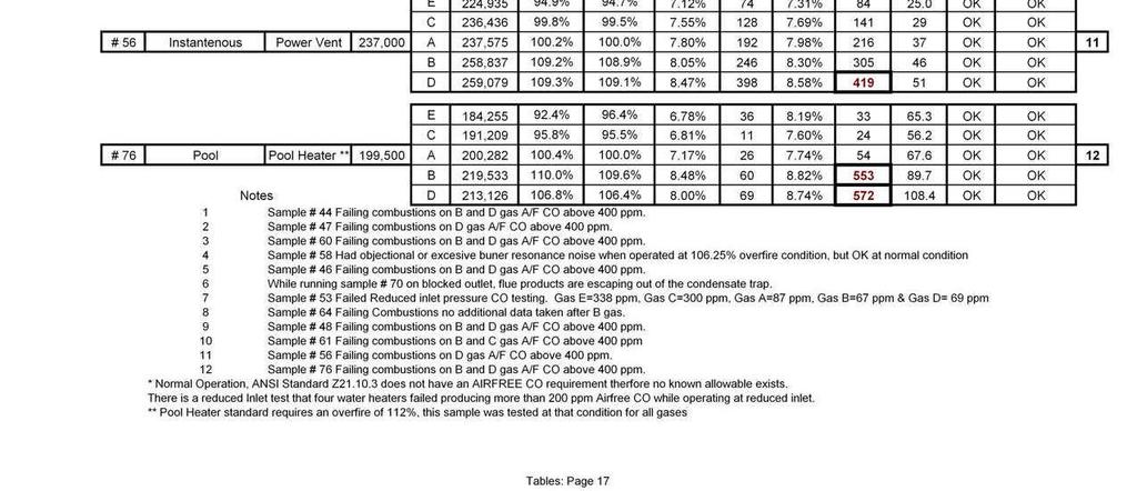
24 Pool Heaters Included with the Water Heaters information below. Unit Heaters Four (4) manufacturers contributed a total of four (4) unit heaters for this test program. All were power vented products with inputs ranging from 30,000 BTU/Hr to 250,000 BTU/Hr. ANSI Z83.8 Duct Furnace and Unit Heaters is the standard for these appliances. Most of the operational tests are the same or similar to the furnace standard. Combustion Tests: The maximum Air Free CO is 400 ppm (0.04%) after 3 minutes at normal inlet pressures, an additional 2 minutes at reduced inlet pressure, a total run time of 15 minutes before the increased rate combustion test, and followed up with reduced voltage (85% of rating voltage). Burner Operating Characteristics: B.O.C. tests are similar to ANSI Z21.47 Section 2.9 for appliances with inlet pressures less than 14 inches water column. They consist of 1/3 turn down, 87% of minimum input, 4 inlet and voltage variations: 85 and 110 percent of rating plate voltage. These tests are to be performed at cold (room ambient) and hot test conditions. Observations and Comments: An emission test failure was found on one sample appliance while operating on B and D gases; while operating on B gas the actual over-fire rate was measured at 117.2%. D gas increased rate was higher with an over-fire rate of 118.1%. Both of these gases caused higher than allowable Air Free CO emissions. Blocked vent outlet test showed similar results on the two highest Wobbe Index gases, producing higher than the 400 ppm limit for Air Free CO. 24
25 Water Heaters and Pool Heaters Four (4) water heater manufacturers and one (1) pool heater manufacturer provided a total of nineteen (19) water heaters and one (1) pool heater for inclusion in this program. There was a mix of both commercial and residential water heaters along with the one pool heater. Sample appliance breakdowns by type of the nineteen water heating products are: 2 Residential Power Vented 4 Residential Natural Draft 2 Residential Ultra Low NOx 2 Commercial Power Vented 4 Commercial Natural Draft 2 Residential Instantaneous Tankless 1 Commercial Instantaneous Tankless 1 Commercial /Residential Condensing 1 Pool Heater ANSI Z covers storage water heaters with input rates 75,000 BTU/hr and below. ANSI Z applies to storage water heaters with input rates higher than 75,000 BTU/Hr and all instantaneous water heaters. ANSI Z21.56 covers pool heaters. Notable Differences in Test Procedures from the Generic Information Given Above The ANSI water heater standards have no Normal combustion test/co requirement, but for this program data was recorded for a Normal condition. Per the standards, combustion samples are required to be taken at reduced inlet pressure with an allowable CO of 200 ppm air free, and increased/overfire condition with an allowable CO Air Free of 400 ppm. The overfire rate requirement is % for water heaters (see pool heaters difference below). Hence, there is no CO allowable given for normal operation, and it could be either 200 or 400 ppm. For combustion testing the water heater is filled with 70 2 F water. The heater is placed in operation and after fifteen minutes of continuous operation at normal inlet test pressure, the combustion testing begins with an additional five minutes of operation at increased rate and then an additional five minutes of operation at reduced inlet pressure. If equipped with a fan/blower power combustion system, an additional test is run at 85% of line voltage (see further discussion below). For the one pool heater included in the test program, the pool heater standard (ANSI Z21.56) requires an increased rate of 112% with AFCO requirement of less than 400 ppm (0.04%) at the increased rate. For both normal rate and reduced inlet pressure the allowable CO Air Free is 200 ppm (0.02%). Combustion Tests; The combustion samples were taken at the water heater s flue outlet without a vent system connected to the draft hood as detailed by the ANSI standard. Power vent 25
26 appliances are required to pass combustion tests at reduced voltage (85%) of data plate stated voltage and with both the maximum and minimum vent lengths specified by the manufacturer. Again, to look at trends, only the minimum vent length was tested in this program. For an appliance equipped with a draft hood (atmospheric vented) two sample probes were placed in the flue (on either side of the typical restrictor baffle) and joined together in order to obtain an average sample before dilution in the draft hood. Once the probe system was placed in the appliance, it was locked in position and not moved for the testing of the other gases. The goal being to have consistency of data in what, sometimes, can become a stratified sample. As noted above the initial start up procedure requires the water heater to be filled with 70º F water. For continuous operation, water flow through the water heater was adjusted to maintain a water outlet temperature of 130F with a 70ºF inlet water flow. In order to maintain these requirements the 1,500 gallon tempering water system was used for all water heater testing. For almost all products, reduced inlet gas pressure was not something that resulted in increased emissions; hence, those results were not detailed on the consolidated test sheets. An exception was made for sample # 53 (Atmospheric, Commercial Tank Style Water Heater) which did experience issues at reduced inlet pressure. As the Wobbe Index decreased, the CO air free emissions levels increased and failed on gases C and E. NO X: NO X emissions were recorded along with CO 2 and CO samples, this extra data aids in the determination of what effects the higher Wobbe Indexes had on combustions during the use of different gases. The reader is cautioned that the NOx emissions recorded were not done under the same protocol as required for California and Texas EPA emission testing. See the more detailed explanation under Boilers and Furnaces sections of this report. Burner Operating Characteristics: One Low NO X appliance had burner resonance noise at increased rates on both higher Wobbe Gases ( B and D ). Observations and Comments: NO X readings followed the changes in Wobbe Index wherein the higher Wobbe Index gas resulted in higher NO X emissions. One Low NO X appliance had burner resonance noise at increased rate on both higher Wobbe Index gases. Combustion failures were found primarily at increased rates on the high Wobbe B and D gases. One appliance failed while operating on B gas, but had passing results on the highest Wobbe D gas. The cause appears to be due to a rate reduction on D gas, possibly due to excessive heat on the manifold pipe and orifice. 26
27 The decision was made to discontinue testing on one appliance (#64) that had failing combustions operating on increased rate with A gas along with a failing normal condition on B gas. The data was left in the table because it does show that a sensitive product that just barely fails (or passes) the overfire condition on Gas A can be dramatically impacted by a Wobbe change when tested at normal inlet pressure with a gas that mimics the % overfire condition. The test difference was that on gas A at overfire condition, the manifold pressure was increased to obtain the overfire. By changing the gas but leaving the manifold pressure at normal condition, the effect of a higher input was much more dramatic than achieving the overfire by increasing the manifold pressure to achieve the overfire effect. 27
28 Tables Note When reviewing the individual data sheets, please be advised that any value of CO recorded as 1050 ppm means that the upper range of the CO measuring instrument has been exceeded. It was not determined how far above 1050 ppm the actual value was, but the 1050 value was used for computational purposes in determining the minimum Air Free CO value that the results could have been. Therefore, there are times where the CO values may be recorded (air free) on the data sheets as 1200, 2000, or more ppm. This is just the result of the mathematics of using 1050 ppm (maximum range of instrument) for the CO value inserted into the air free calculation. Hence, the value is at least the number shown and may be much higher. Most likely any recorded CO air free value over 1100 ppm in the tables was generated because the measured CO was above 1050 ppm 4. 4 To make that determination: Multiply the stated value in the table by 12.2% and then divide the resultant value by the recorded CO 2. This will give the reader the base CO value used for the calculation. 28
29 Test Sample Number Furnace (Household) Rooftop or Outdoor Furnace Boiler Water Heater (Domestic Tank) Water Heater (Commercial- Tank) Water Heater (Instantenous) Free Standing Range CookTop Range Oven Dryer Unit Heater Room Heater Fireplace Wall Furnace Comment on Venting, Efficiency, Sub-type of product, etc Number of samples tested/data presented (Total 78) 1 X High Effeciency ( 90+ ) Furnace 2 X 80 + Efficiency Furnace 3 X 80 + Efficiency Furnace 4 X 80 + Efficiency Furnace 5 X Heavy Duty 30" Freestanding Range 6 X Heavy Duty 48" Free Standing Range 7 X High Effeciency ( 90+ ) Furnace 8 X 80 + Efficiency Furnace 9 X 80 + Efficiency Furnace 10 X High Effeciency ( 90+ ) Furnace 11 X Clothes Dryer 12 X Clothes Dryer 13 X Clothes Dryer 16 X Non-Condensing Boiler Power vent 17 X Clothes Dryer 18 X Clothes Dryer 19 X Clothes Dryer 20 X 30" Free Standing Conventional Range 21 X 80 + Efficiency Furnace 22 X 80 + Efficiency Furnace 23 X Heavy Duty 48" Free Standing Range 24 X High Effeciency ( 90+ ) 25 X Clothes Dryer 26 X Cook Top 28 X Unit Heater Power Vent Residential Garage Type 29 X High Effeciency ( 90+ ) Furnace 30 X High Effeciency ( 90+ ) Furnace 31 X High Effeciency ( 90+ ) Furnace 32 X Wall Oven 33 X Cook Top 34 X Clothes Dryer (Apartment Size with Washer Attached) 35 X Clothes Dryer 36 X High Effeciency ( 90+ ) Furnace 37 X Power Vent Boiler (80+% Efficiency) 38 X Condensing (90+% Efficiency) Modulating Boiler 39 X Atmospheric Vent (Draft Hood) Boiler 40 X Power Vent Boiler (80+% Efficiency) 41 X Atmospheric Vent (Draft Hood) Boiler 42 X Atmospheric Vent (Draft Hood) Boiler 43 X Power Vent Residential Water Heater 44 X Atmospheric Vent (Draft Hood) Residential Water heater 45 X Atmospheric Vent (Draft Hood) Commercial Water heater 46 X Power Vent Commercial Water Heater 47 X Atmospheric Vent (Draft Hood) Residential Water heater 48 X Tankless/Instantaneous Water heater 49 X Power Vent Boiler (80+% Efficiency) 50 X Atmospheric Vent (Draft Hood) Boiler 51 X Condensing (90+% Efficiency) Modulating Boiler 52 X Condensing (90+% Efficiency) Modulating Boiler 53 X Atmospheric Vent Commercial Water Heater 54 X Cook Top 55 X 30" Free Standing 56 X Tankless/Instantaneous Water heater 57 X Ceramic Infra Red Style Unvented Room Heater 58 X Atmospheric Vent Ultra Low Nox Residential Water Heater 59 X Power Vent Residential Water Heater Tables: Page 1 29
30 Test Sample Number Furnace (Household) Rooftop or Outdoor Furnace Boiler Water Heater (Domestic Tank) Water Heater (Commercial- Tank) Water Heater (Instantenous) Free Standing Range CookTop Range Oven Dryer Unit Heater Room Heater Fireplace Wall Furnace Comment on Venting, Efficiency, Sub-type of product, etc. 60 X Atmospheric Vent (Draft Hood) Residential Water heater 61 X Tankless/Instantaneous Water heater 62 X Power Vent Commercial Water Heater 64 X Atmospheric Vent (Draft Hood) Commercial Water heater 65 X Atmospheric Vent (Draft Hood) Commercial Water heater 66 X Wall Furnace 68 X Atmospheric Vent (Draft Hood) Residential Water heater 69 X Atmospheric Vent Ultra Low Nox Residential Water Heater 70 X Condensing (90+% Efficiency) Water Heater 71 X Wall Furnace 72 X Wall Furnace 75 X Fireplace Concentric Direct vent 76 X Pool Heater 77 X Fireplace Concentric Direct vent 78 X Fireplace Concentric Direct vent 80 X Unit Heater Commercial Size 81 X Unit Heater Power Vent Residential Garage Type 82 X Blue Flame type unvented room heater 83 X Blue Flame type unvented room heater 84 X Unit Heater Commercial Size 85 X Condensing (90+% Efficiency) Modulating Boiler 86 X Gun Style Power Burner (80+ % efficiency) Some products submitted were not tested because they did not meet the parameters of the test program Tables: Page 2 30

31 31


32 32

33 33


34 34


35 35


36 36
37 37
38 38
39 39


40 40

41 41


42 42


43 43


44 44


45 45
COMBUSTION APPLIANCE SAFETY INSPECTION FOR VENTED APPLIANCES*
 COMBUSTION APPLIANCE SAFETY INSPECTION FOR VENTED APPLIANCES* *Vented appliances refer to natural draft appliances equipped with a barometric draft regulator or Category I appliances equipped with a draft
PVE SERIES POWER VENTER SYSTEM MANUAL
 PVE SERIES POWER VENTER SYSTEM MANUAL Contents Page I. Typical Venting System Components 2 II. System Operation 3 III. Power Venter Sizing 3,4 IV. Installation Safety Instructions 5,6 V. Installation of
Overview of Gas Range Types
 Residential Gas Ranges Overview of Types How Carbon Monoxide is Emitted How They Operate Overview of Gas Range Types Rick Karg R.J. Karg Associates www.karg.com November 2001 2001 R.J. Karg Associates
POWER VENTER. Model: PVE Series
 POWER VENTER Model: PVE Series CONTENTS Typical Venting System Components... System Operation... Power Venter Sizing... Installation Safety Instructions... Installation of Power Venter... Connecting Power
Combustion Safety. RESNET Conference San Antonio, TX February 27, Presented by Rich Moore Lightly Treading Energy & Design Denver, CO
 Combustion Safety RESNET Conference San Antonio, TX February 27, 2006 Presented by Rich Moore Lightly Treading Energy & Design Denver, CO Goals of this session Recognize the need for combustion safety
Gas Safety. Syllabus. For. Gas Appliance Service. Certificate of Qualification Examination. (Formerly Class C)
") Gas Safety Syllabus For Gas Appliance Service Certificate of Qualification Examination (Formerly Class C) 1. Prerequisites to obtain a gas appliance service certificate of qualification An applicant for
Gas Safety Syllabus For Gas Appliance Service Certificate of Qualification Examination (Formerly Class C) 1. Prerequisites to obtain a gas appliance service certificate of qualification An applicant for
RULE 3.23 NATURAL GAS-FIRED WATER HEATERS, SMALL BOILERS, AND PROCESS HEATERS (Adopted 10/03/2016)
") RULE 3.23 NATURAL GAS-FIRED WATER HEATERS, SMALL BOILERS, AND PROCESS HEATERS (Adopted 10/03/2016) A. PURPOSE The purpose of this rule is to limit the emissions of oxides of nitrogen (NOx) from the use
RULE 3.23 NATURAL GAS-FIRED WATER HEATERS, SMALL BOILERS, AND PROCESS HEATERS (Adopted 10/03/2016) A. PURPOSE The purpose of this rule is to limit the emissions of oxides of nitrogen (NOx) from the use
BEST DRAFT CONTROL: MANUAL DAMPERS IN MULTIPLE BOILER SYSTEMS
 BEST DRAFT CONTROL: MANUAL DAMPERS IN MULTIPLE BOILER SYSTEMS WHITEPAPER Decades of evolving codes have led to much confusion over how dampers can and cannot be used. Contrary to popular belief, manual
In accordance with the Department of Labor and Industry s statute , Subd. 11,
 In accordance with the Department of Labor and Industry s statute 326.0981, Subd. 11, This educational offering is recognized by the Minnesota Department of Labor and Industry as satisfying 1.5 hours of
TANKLESS WATER HEATING
 TANKLESS WATER HEATING With any gas appliance, it is essential that the gas supply system be properly sized to support the BTU load of the system. Tankless water heaters can be a great solution to provide
USER S INFORMATION MANUAL
 USER S INFORMATION MANUAL HOT WATER HEATING BOILERS DOMESTIC WATER HEATERS 150,000-300,000 Btu/hr MODELS EB-EWU-02 IMPORTANT INSTALLER - AFFIX INSTALLATION MANUAL ADJACENT TO THE BOILER CONSUMER - RETAIN
Draft Control D R A F T C O N T R O L G U I D E w w w. f i e l d c o n t r o l s. c o m August 2007
 Draft D R A F T C O N T R O L G U I D E w w w. f i e l d c o n t r o l s. c o m August 2007 Draft For proper operation and efficient fuel consumption in oil, gas, and/or coal-fired heating appliances,
A hydronic system controls comfort by delivering heated or cooled fluid to the conditioned space through pipes.
 Introduction to Hydronics A hydronic system controls comfort by delivering heated or cooled fluid to the conditioned space through pipes. Hydronic heating systems use hot water or steam to deliver the
DIVISION WALL-HUNG STAINLESS STEEL HEATING BOILERS
 XPAK FT TYPE H - MODELS 088AR-398A SUGGESTED SPECIFICATIONS Catalog No.: 2100.91 Effective: 05/01/15 Replaces: new DIVISION 23 52 33.13 WALL-HUNG STAINLESS STEEL HEATING BOILERS PART 1 - GENERAL 1.1 SUMMARY
RESNET National Conference New Orleans, LA. February 16, 2009 Presented by Rich Moore Invisible Energy Denver, CO
 RESNET National Conference New Orleans, LA. February 16, 2009 Presented by Rich Moore Invisible Energy Denver, CO rgalenmoore1@msn.com This session will address the basics of combustion and the latest
DIVISION FINNED WATER-TUBE WATER HEATERS
 DELTA LIMITED, TYPE WH - MODELS 399B-899B SUGGESTED SPECIFICATIONS Catalog No.: 3500.97B Effective: 04-01-17 Replaces: 11-15-08 DIVISION 23 52 33.13 FINNED WATER-TUBE WATER HEATERS - GENERAL 1.1 SUMMARY
SIZING HANDBOOK & APPLICATION GUIDE
 SIZING HANDBOOK SIZING HANDBOOK & APPLICATION GUIDE Chimney & Gas Vent For Capacities to 100 Million B.T.U. The primary aim of this Sizing Handbook is to provide more detailed guidance on appliance venting
POWER VENTER SYSTEM. Model: PVO-300, PVO-600
 POWER VENTER SYSTEM Model: PVO-300, PVO-600 Included is one ETL and cetl listed Power Venter to be used primarily with a single 120VAC controlled oil fired furnace, boiler, or water heater. The PVO may
d. Portable water heaters used exclusively for underwater diving operations.
 RULE 360. BOILERS, WATER HEATERS, AND PROCESS HEATERS (0.075 2 MMBtu/hr) EMISSIONS OF OXIDES OF NITROGEN FROM LARGE WATER HEATERS AND SMALL BOILERS. (Adopted 10/17/2002, revised xx/xx/xxxx) A. Applicability
Revitalize Building Mechanical Systems (4619)
") SECTION 235216 FIRE-TUBE CONDENSING BOILERS PART 1 - GENERAL 1.1 RELATED DOCUMENTS A. Drawings and general provisions of the Contract, including General and Supplementary Conditions and Division 01 Specification
SECTION 235216 FIRE-TUBE CONDENSING BOILERS PART 1 - GENERAL 1.1 RELATED DOCUMENTS A. Drawings and general provisions of the Contract, including General and Supplementary Conditions and Division 01 Specification
RECOMMENDED PROCEDURES FOR THIRD-PARTY PREVENTATIVE MAINTENANCE PROVIDERS
 RECOMMENDED PROCEDURES FOR THIRD-PARTY PREVENTATIVE MAINTENANCE PROVIDERS 1 Contents Introduction... 3 Portfolio Energy Goals... 3 Purpose of This Document... 3 Gas Furnaces... 4 Electric Furnaces... 7
A. Product Data: Include rated capacities, furnished specialties and accessories.
 BASE BID: SECTION 15542 FUEL-FIRED RADIANT HEATERS PART 1 - GENERAL 1.1 SUMMARY A. Furnish and install a Co-Ray-Vac Low Intensity Vented Infrared Radiant Vacuum Gas Heating System. System must be certified
Internet Version for Reference Only INDUCED DRAFT COMMERCIAL WATER HEATERS SUPPLEMENT INSTRUCTIONS TO PART #
 INDUCED DRAFT COMMERCIAL WATER HEATERS SUPPLEMENT INSTRUCTIONS TO PART #238-39387-00 THIS INSTRUCTION SUPPLEMENT IS ONLY INTENDED TO GIVE INSTALLATION INSTRUCTIONS AND INFORMATION RELATED TO THE INDUCED
State of ALASKA, Weatherization Assistance Program. Technical Support Document. Combustion Safety
 5.3.1A(2) Page 1 of 2 State of ALASKA, Weatherization Assistance Program Technical Support Document Combustion Safety This document is intended to support in detail the Combustion Safety Test Report. The
HIGH-EFFICIENCY COMMERCIAL GAS WATER HEATER 3-Year Tank Warranty 1-Year Parts Warranty
 HIGH-EFFICIENCY COMMERCIAL GAS WATER HEATER 3-Year Tank Warranty 1-Year Parts Warranty Stainless Steel Tank with Submerged Combustion High grade 444 stainless steel tank with brass connections for years
RESNET National Conference New Orleans, La. February 15, 2009 Presented by Rich Moore Invisible Energy Denver, CO
 RESNET National Conference New Orleans, La. February 15, 2009 Presented by Rich Moore Invisible Energy Denver, CO rgalenmoore1@msn.com Effective insulation and air sealing treatments can make a huge difference
INSTALLATION AND OPERATION MANUAL FOR 2 STAGE RIELLO BURNER ADDENDUM TO ( Mo 437 manual )
") INSTALLATION AND OPERATION MANUAL FOR 2 STAGE RIELLO BURNER ADDENDUM TO ( Mo 437 manual ) FOR USE WITH MODEL: OH6FX072DV4 PLEASE READ THESE INSTRUCTIONS PRIOR TO INSTALLATION, INITIAL FIRING, AND BEFORE
INSTALLATION AND OPERATION MANUAL FOR 2 STAGE RIELLO BURNER ADDENDUM TO ( Mo 437 manual ) FOR USE WITH MODEL: OH6FX072DV4 PLEASE READ THESE INSTRUCTIONS PRIOR TO INSTALLATION, INITIAL FIRING, AND BEFORE
Exhaust Duct Design Page 1 of (C)
") Exhaust Duct Design Page 1 of 16 2016-10-07 (C) Oven Exhaust Guide Version: R5 Exhaust Duct Design The following section is for your guidance in establishing a design to suit your Exhaust duct design requirements.
Exhaust Duct Design Page 1 of 16 2016-10-07 (C) Oven Exhaust Guide Version: R5 Exhaust Duct Design The following section is for your guidance in establishing a design to suit your Exhaust duct design requirements.
advanced : technology
 ETERNA L H Y B RID advanced water heating advanced : technology 2 Eternal hybrid is the only water heating system that combines the best of tank and tankless features in one. The patented, powerful design
Typical Specifications For: ADVANTUS TM DOMESTIC HOT WATER SUPPLY Models AV(W)0500 AV(W)4000
0500 AV(W)4000") s AV(W)0500 AV(W) The domestic hot water boiler shall be a Camus ADVANTUS TM model having a recovery capacity of gph (lph) at 100ºF (56ºC) for DHW The domestic hot water boiler shall be design certified
s AV(W)0500 AV(W) The domestic hot water boiler shall be a Camus ADVANTUS TM model having a recovery capacity of gph (lph) at 100ºF (56ºC) for DHW The domestic hot water boiler shall be design certified
SAMPLE SPECIFICATION FOR RIELLO ARRAY MODULATING BOILER
 SAMPLE SPECIFICATION FOR RIELLO ARRAY MODULATING BOILER PART 1 GENERAL 1.01 RELATED DOCUMENTS A. ANSI Z21.13 American National Standard for Gas-Fired Low Pressure Steam and Hot Water Boilers B. ASME Section
SIZING HANDBOOK & APPLICATION GUIDE
 SIZING HANDBOOK SIZING HANDBOOK & APPLICATION GUIDE Chimney & Gas Vent For Capacities to 100 Million B.T.U. The primary aim of this Sizing Handbook is to provide more detailed guidance on appliance venting
Typical Specifications For: ADVANTUS TM DOMESTIC HOT WATER SUPPLY Models AV(W)0500 AV(W)4000
0500 AV(W)4000") s AV(W)0500 AV(W) The domestic hot water boiler shall be a Camus ADVANTUS TM model having a recovery capacity of gph (lph) at 100ºF (56ºC) for DHW The domestic hot water boiler shall be design certified
s AV(W)0500 AV(W) The domestic hot water boiler shall be a Camus ADVANTUS TM model having a recovery capacity of gph (lph) at 100ºF (56ºC) for DHW The domestic hot water boiler shall be design certified
Electric radiator tests
 Electric radiator tests Carried out for Haverland By P Stonard 16 July 2010 Electric radiator tests Carried out for: Haverland Avda San Martin De Valdeigiesias Km-2,200 Alcorcon MADRID 28925 Spain Contract:
FINNED WATER-TUBE POOL HEATERS
 HI DELTA, TYPE P - MODELS 992C-2342C SUGGESTED SPECIFICATIONS Catalog No.: 6000.611 Effective: 10-31-16 Replaces: NEW FINNED WATER-TUBE POOL HEATERS - GENERAL 1.1 SUMMARY A. Section includes gas-fired,
FIELD DRAFT CONTROLS
 INDEX TYPE M... 7-7 TYPE MG-1... 7-8 TYPE M+MG2... 7-9 TYPE RC... 7-6 INTRODUCTION... 7-2 7-5 Expert Service. Quality Products. Since 1960. www.eccosupply.ca 7-1 For proper operation and efficient fuel
PROPOSED October 15, 2013
 RULE 4308 BOILERS, STEAM GENERATORS, AND PROCESS HEATERS 0.075 MMBtu/hr to less than 2.0 MMBtu/hr (Adopted October 20, 2005, Amended December 17, 2009, Amended [rule adoption date]) 1.0 Purpose The purpose
Draft Controls. When to use a Draft Control
 Draft s For proper operation and efficient fuel consumption in oil, gas and/or coal-fired heating appliances, draft must remain constant. When it is, combustion is more complete, fuels are utilized efficiently,
96% AFUE Efficiency CONDENSING RESIDENTIAL GAS BOILERS CONTROL WITH ADVANCED USER FEATURES MODELS FROM 80,000 TO 285,000 BTU/HR
 CONDENSING RESIDENTIAL GAS BOILERS CONTROL WITH ADVANCED USER FEATURES MODELS FROM 80,000 TO 285,000 BTU/HR 5:1 FIRING RATE MODULATION LESS THAN 20 ppm NOx DIRECT VENT FLEXIBILITY TO 100 FEET 96% AFUE
SUPER HIGH EFFICIENCY WATER HEATERS SUPPLEMENT TO INSTRUCTION MANUAL P/N (Replaces pg. 2 in instruction manual.) CONGRATULATIONS!
 CONGRATULATIONS!") SUPER HIGH EFFICIENCY WATER HEATERS SUPPLEMENT TO INSTRUCTION MANUAL P/N 238-44219-00 (Replaces pg. 2 in instruction manual.) CONGRATULATIONS! You have just purchased one of the finest water heaters on
SUPER HIGH EFFICIENCY WATER HEATERS SUPPLEMENT TO INSTRUCTION MANUAL P/N 238-44219-00 (Replaces pg. 2 in instruction manual.) CONGRATULATIONS! You have just purchased one of the finest water heaters on
Up to 94.6% Thermal Efficiency HIGH EFFICIENCY COMMERCIAL CONDENSING BOILERS OPERATING CONTROL FEATURING A BUILT-IN CASCADING SEQUENCER
 HIGH EFFICIENCY COMMERCIAL CONDENSING BOILERS OPERATING CONTROL FEATURING A BUILT-IN CASCADING SEQUENCER 5 MODELS: 399,000 800,000 BTU/HR FIRING RATE MODULATION TO 5:1 LESS THAN 30 ppm NOx DIRECT-VENT
Qualifies for up to $ 1500 Energy Tax Credit! CONDENSING RESIDENTIAL GAS BOILERS CONTROL WITH ALL NEW, ADVANCED USER FEATURES
 CONDENSING RESIDENTIAL GAS BOILERS CONTROL WITH ALL NEW, ADVANCED USER FEATURES 5 FLOOR-STANDING AND 5 WALL-MOUNT MODELS FROM 50,000 TO 285,000 BTU/HR FIRING RATE MODULATION TO 5:1 LESS THAN 20 ppm NOx
WATER-TUBE POOL HEATERS
 XTHERM, TYPE P - MODELS 1005A-2005A SUGGESTED SPECIFICATIONS Catalog No.: 6000.63B Effective: 3-01-15 Replaces: 9-01-09 WATER-TUBE POOL HEATERS PART 1 - GENERAL 1.1 SUMMARY A. Section includes condensing,
DIVISION FINNED WATER-TUBE WATER HEATERS
 HI DELTA, TYPE WH - MODELS 992C-2342C SUGGESTED SPECIFICATIONS Catalog No.: 3500.932A Effective: 04-01-17 Replaces: 10-31-16 DIVISION 23 52 33.13 FINNED WATER-TUBE WATER HEATERS - GENERAL 1.1 SUMMARY A.
ASGE NATIONAL TECHNICAL CONFERENCE AMERICAN SOCIETY OF GAS ENGINEERS
 ASGE NATIONAL TECHNICAL CONFERENCE AMERICAN SOCIETY OF GAS ENGINEERS MGM GRAND HOTEL LAS VEGAS JUNE 7 9, 2010 BOB JACKSON 1 REFERENCES 1. Household Cooking Gas Appliances, American National Standard ANSI
INFORMATION FOR TANKLESS WATER HEATERS
 GAS PIPING INFORMATION FOR TANKLESS WATER HEATERS Details Details regarding regarding properly properly sized sized gas lines lines for for use use with with tankless tankless water water heaters heaters
ATTACHMENT D #1 - HVAC (OIL) - SINGLE FAMILY DWELLINGS Category C: OIL
 - SINGLE FAMILY DWELLINGS Category C: OIL") LINE ITEM # ATTACHMENT D #1 - HVAC (OIL) - SINGLE FAMILY DWELLINGS Category C: OIL LINE ITEM DETAIL Labor Material FURNACE COMPONENTS 1 Furnish & Install Sight-Impaired Thermostat For Heating and Cooling
LINE ITEM # ATTACHMENT D #1 - HVAC (OIL) - SINGLE FAMILY DWELLINGS Category C: OIL LINE ITEM DETAIL Labor Material FURNACE COMPONENTS 1 Furnish & Install Sight-Impaired Thermostat For Heating and Cooling
Combustion Sources of Carbon Monoxide. Carbon Monoxide Repairs. Topics Addressed in Session. Why CO can be Harmful Inhalation Time and Symptoms
 Affordable Comfort Conference 2002 Saturday, April 20, 8:00 12:00 Rick Karg R.J. Karg Associates www.karg.com April 2002 2002 R.J. Karg Associates Topics Addressed in Session Combustion sources of CO.
Whole House Combustion Appliance Safety Test Procedure for Pacific Gas and Electric Company (PG&E) Advanced Home Upgrade 2019
 Advanced Home Upgrade 2019") Whole House Combustion Appliance Safety Test Procedure for Pacific Gas and Electric Company (PG&E) Advanced Home Upgrade 2019 Note: This procedure is subject to revision or modification by PG&E at any
Whole House Combustion Appliance Safety Test Procedure for Pacific Gas and Electric Company (PG&E) Advanced Home Upgrade 2019 Note: This procedure is subject to revision or modification by PG&E at any
MODULATING CONTROL OF LOW NO X BURNERS
 MODULATING CONTROL OF LOW NO X BURNERS ABSTRACT Manufacturers of today s wall-fired low NO X burners (LNB) recommend a single-position secondary air volume control for in-service burners. Air register
Gas Piping Facts. Information for properly sizing gas lines for use with tankless water heaters and other gas appliances TANKLESS WATER HEATING
 TANKLESS WATER HEATING Gas Piping Facts Information for properly sizing gas lines for use with tankless water heaters and other gas appliances With any gas appliance, it is essential that the gas supply
SECTION HEATING BOILERS
 SECTION 23 52 00 HEATING BOILERS PART 1 - GENERAL 1.1 SUMMARY A. Section includes boilers, controls and boiler trim, steam and condensate connections, hot water connections, fuel burning system and connections,
DIVISION FINNED WATER-TUBE BOILERS
 MVB, TYPE H - MODELS 2503-4003 SUGGESTED SPECIFICATIONS Catalog No.: 2000.934A Effective: 04-01-14 Replaces: 06-01-13 DIVISION 23 52 33.13 FINNED WATER-TUBE BOILERS PART 1 - GENERAL 1.1 SUMMARY A. Section
FINNED WATER-TUBE POOL HEATERS
 HI DELTA, TYPE P - MODELS 502C-902C SUGGESTED SPECIFICATIONS Catalog No.: 6000.601A Effective: 07-12-18 Replaces: 10-31-16 FINNED WATER-TUBE POOL HEATERS - GENERAL 1.1 SUMMARY A. Section includes gas-fired,
DIVISION FINNED WATER-TUBE BOILERS
 MVB, TYPE H - MODELS 503A-2003A SUGGESTED SPECIFICATIONS Catalog No.: 2000.932C Effective: 04-01-14 Replaces: 07-15-13 DIVISION 23 52 33.13 FINNED WATER-TUBE BOILERS PART 1 - GENERAL 1.1 SUMMARY A. Section
Section 2, Reference publications: Updated the referenced publications to the current editions.
 Summary of Substantive Changes between the 2014 and the 2015 editions of ANSI Z21.10.3 CSA 4.3 Gas fired water heaters, volume III, storage water heaters with input ratings above 75,000 Btu per hour, circulating
INDITHERM. Low temperature gas burners
 INDITHERM Low temperature gas burners 1-2.3-1 High turndown for maximum operation flexibility. Maximum capacities up to 1800 kw. Designed for firing in indirect fired processes. Excellent combustion throughout
FGR. Installation, Operation and Startup Instruction Manual FOR FLUE GAS RECIRCULATION SYSTEM. FGR-8 through FGR-22 (25 HP to 1000 HP)
") FGR Installation, Operation and Startup Instruction Manual FOR FLUE GAS RECIRCULATION SYSTEM FGR-8 through FGR-22 (25 HP to 1000 HP) Gas, Light Oil or Combination MANUFACTURED BY JOHN ZINK COMPANY, LLC
FGR Installation, Operation and Startup Instruction Manual FOR FLUE GAS RECIRCULATION SYSTEM FGR-8 through FGR-22 (25 HP to 1000 HP) Gas, Light Oil or Combination MANUFACTURED BY JOHN ZINK COMPANY, LLC
MODELS LFP4218/LFP6018 TOP VENT GAS FIREPLACE
 MODELS LFP4218/LFP6018 TOP VENT GAS FIREPLACE PFS APPROVED FOR NATURAL GAS OR PROPANE GAS Z21.50-2014 If your plans do not allow for the venting system as outlined previously in the installing chimney/vent
WATER-TUBE POOL HEATERS
 XTHERM, TYPE P - MODELS 2505-4005 SUGGESTED SPECIFICATIONS Catalog No.: 6000.70 Effective: 09-15-16 Replaces: NEW WATER-TUBE POOL HEATERS - GENERAL 1.1 SUMMARY A. Section includes condensing, gas-fired
SECTION TESTING, ADJUSTING, AND BALANCING FOR HVAC
 PART 1 GENERAL 1.01 SECTION INCLUDES SECTION 23 0593 TESTING, ADJUSTING, AND A. Testing, adjustment, and balancing of air systems. B. Testing, adjustment, and balancing of hydronic, steam, and refrigerating
R-RCM & R-RSB SERIES
 R-RCM & R-RSB SERIES CHEESEMELTER & SALAMANDER BROILERS INSTALLATION - OPERATION - MAINTENANCE CHEESEMELTERS R-RCM-24 R-RCM-36 R-RCM-48 R-RCM-60 SALAMANDERS R-RSB-24 R-RSB-36 R-RSB-48 Telephone: (802)
CYLINDER NOT INCLUDED
 OPERATING INSTRUCTIONS AND OWNER S MANUAL Model # HS125NG / MH125LP / HS125LP READ INSTRUCTIONS CAREFULLY: Read and follow all instructions. Place instructions in a safe place for future reference. Do
Performance Report 2009 Chimfex
 Performance Report 29 Chimfex May, 29 Prepared for: Terry Jones, Operations Mgr Orion Safety Products 2832 Saint Michaels Rd Easton, MD 2161 P: 41-822-318 E: terry@orionsignals.com Terry, OMNI Environmental
SAMPLE SPECIFICATIONS CONTINUOUS MONITORING SYSTEM (Insitu)
") PART 1 - GENERAL A. RELATED DOCUMENTS SAMPLE SPECIFICATIONS CONTINUOUS MONITORING SYSTEM (Insitu) Federal, State, and local requirements as applicable. Attached Permit Attached drawings B. SUMMARY 1. Provide
PART 1 - GENERAL A. RELATED DOCUMENTS SAMPLE SPECIFICATIONS CONTINUOUS MONITORING SYSTEM (Insitu) Federal, State, and local requirements as applicable. Attached Permit Attached drawings B. SUMMARY 1. Provide
LATTNER BOILER COMPANY 9.5 HP Low-NOx Installation and Start-Up Checklist for Dry Cleaners
 1 1. General Installation Information (to be completed by technician) Date installed: Location (city & state): Cleaner s name: National Board number (boiler): Installed by (company): Installed by (technician):
REGISTRATION EXAMINATION, NOVEMBER 2016 LICENSED GASFITTER QUESTION AND ANSWER BOOKLET. Time allowed THREE hours
 Affix label with Candidate Code Number here. If no label, enter candidate Number if known No. 993 REGISTRATION EXAMINATION, NOVEMBER 06 LICENSED GASFITTER INSTRUCTIONS QUESTION AND ANSWER BOOKLET Time
XTHERM, TYPE WH - MODELS 1005A- 2005A DIVISION COMMERCIAL, WATER-TUBE, CONDENSING GAS DOMESTIC WATER HEATERS
 XTHERM, TYPE WH - MODELS 1005A- 2005A Catalog No.: 3500.801 Effective: 11-15-14 Replaces: NEW PART 1 - GENERAL 1.1 SUMMARY DIVISION 23 34 36.29 COMMERCIAL, WATER-TUBE, CONDENSING GAS DOMESTIC WATER HEATERS
DIVISION COMMERCIAL, GRID-TYPE, FINNED-TUBE, GAS DOMESTIC WATER HEATERS
 MVB, TYPE WH - MODELS 503A-2003A SUGGESTED SPECIFICATIONS Catalog No.: 3500.952C Effective: 06-25-15 Replaces: 12-22-09 DIVISION 23 34 36.29 COMMERCIAL, GRID-TYPE, FINNED-TUBE, GAS DOMESTIC WATER HEATERS
Title: Standard Operating Procedure for Measurement of Total Hydrocarbon Using a Flame Ionization Detection
 Procedure No: SOP-020 Revision No: 1.0 (January 21, 2011) Page No.: 1 of 7 1. INTRODUCTION AND SCOPE To obtain timely data for the purpose of air quality assessment, air quality trend reporting, and to
 RAYBURN SUPREME/NOUVELLE/355S USER INSTRUCTIONS ISSUE 4 Water Temperature Control Stat. http://www.oilstoves.co.uk/ 1 2 Contents 1. Introduction. 1 2. How Does it Operate? 1 3. Description of Controls.
Gas Safety. Syllabus. For 120kW. Class B gas fitter. Certificate of qualification examination
 Gas Safety Syllabus For 120kW Class B gas fitter Certificate of qualification examination *For individuals enrolled in a B level training course/program after April 01, 2009. Implementation date: January
National Comfort Products 539 Dunksferry Road Bensalem, PA (215) Fax: (215)
 Fax: (215)") National Comfort Products 539 Dunksferry Road Bensalem, PA 19020 (215) 244-1400 1-800-523-7138 Fax: (215) 639-1674 14299575-10/29/2014 NOTE: These installation and maintenance instructions should be left
National Comfort Products 539 Dunksferry Road Bensalem, PA 19020 (215) 244-1400 1-800-523-7138 Fax: (215) 639-1674 14299575-10/29/2014 NOTE: These installation and maintenance instructions should be left
Indiana WX Oil Furnace Inspection Guide
 Indiana WX Oil Furnace Inspection Guide Client: Job # : Address: Phone: Client Interview: Oil Dealer: Date of last service: Comments/Billing information: Standard Inspection / Clean and Tune Follow-up:
USER S INFORMATION MANUAL (2,4)SG13B
SG13B") USER S INFORMATION MANUAL (2,4)SG13B Series Gas Heating/Electric Cooling Package Unit Congratulations......your outdoor heating/cooling package unit is a valuable piece of equipment, designed and manufactured
USER S INFORMATION MANUAL (2,4)SG13B Series Gas Heating/Electric Cooling Package Unit Congratulations......your outdoor heating/cooling package unit is a valuable piece of equipment, designed and manufactured
Figure 10 or Figure 6
 SUPPLEMENT TO INSTRUCTION MANUAL P/N 238-45637-00 and 238-48933-00 (Replaces pg. 32 (238-45637-00) or pg. 28 (238-48933-00) in Wiring Diagram Honeywell A B C VERY HO HO LOW Figure 10 or Figure 6 238-48214-00B
OPERATING AND MAINTENANCE MANUAL
 OPERATING AND MAINTENANCE MANUAL NVPOM-0104 TABLE OF CONTENTS Section Page 1 SPECIFICATIONS...1 1.1 Nova Plus Specifications...1-1 1.2 Warranty...1-2 2 GENERAL BURNER DESCRIPTION...2 2.1 Burner...2-1 2.2
DIVISION FINNED WATER-TUBE BOILERS
 HI DELTA, TYPE H - MODELS 992C-2342C SUGGESTED SPECIFICATIONS Catalog No.: 2000.953 Effective: 10-31-16 Replaces: NEW DIVISION 23 52 33.13 FINNED WATER-TUBE BOILERS - GENERAL 1.1 SUMMARY A. Section includes
Building Department Informational Handout
 City of Sonoma Building Department Informational Handout Residential Water Heaters Handout No: 15 Revised: 4/26/18 A water heater is an appliance designed to supply hot water and is equipped with automatic
MAXIM. Power Combustion Storage Water Heater Gas, Oil or Combination Gas/Oil. 199 to 1200 MBH 125 and 250 Gallon Tanks 15-year Warranty. PVI.
 MAXIM Power Combustion Storage Water Heater Gas, Oil or Combination Gas/Oil ENGINEERED DUPLEX ALLOY 199 to 1200 MBH 125 and 250 Gallon Tanks 15-year Warranty PVI.com The Hard Water Water Heater MAXIM is
Columbia Boiler Company
 EMG Series Boilers Available in Natural Gas & Propane Rev 12012 Columbia Boiler Company PO Box 1070 Pottstown, PA 19464 Tel (610) 473-8457 Fax (610) 367-6800 Website www.columbiaboiler.com Email cbcsales@ptd.net
DIVISION FINNED WATER-TUBE BOILERS
 MVB, TYPE H - MODELS 504A-2004A SUGGESTED SPECIFICATIONS Catalog No.: 2000.933C Effective: 06-25-15 Replaces: 12-21-09 DIVISION 23 52 33.13 FINNED WATER-TUBE BOILERS PART 1 - GENERAL 1.1 SUMMARY A. Section
Introductions HERS Industry HERS Ratings ACCA Standard 12 Resources
 Abe Kruger 2013 RESNET Conference abe@krugersustainabilitygroup.com 215/385-6891 Introductions HERS Industry HERS Ratings ACCA Standard 12 Resources www.krugersustainabilitygroup.com 1 HERS Rater & Trainer/QAD
INTRODUCING THE BRADFORD WHITE 24/7 EXPERT SUPPORT CENTER. TABLE OF CONTENTS. Technical Support: Warranty Support:
 At Bradford White, we believe in giving you a feature-packed, premium product at the best possible price. We proudly build quality and value into each and every product we manufacture. We believe when
Fully-automatic Gas tankless Water Heater USER'S MANUAL FOR MODEL EZ-101 ISO9001 certified
 Fully-automatic Gas tankless Water Heater USER'S MANUAL FOR MODEL EZ-101 ISO9001 certified Thank you for purchasing our fully-automatic gas-fired tankless water heater. Please completely read this Manual
Monitoring Flammable Vapors and Gases in Industrial Processes
 Monitoring Flammable Vapors and Gases in Industrial Processes Flammability Hazards Industrial fires and explosions happen more frequently than most people think. They cause downtime, property damage, injury
Automatic Circulating Water Heaters
 XP CIRCULATING WATER HEATER The ENERGY STAR Qualified A. O. Smith high efficiency condensing XP Water Heater utilizes a state-of-the-art heat exchanger and control technology to provide large volumes of
SPECIFIC APPLIANCES, FIREPLACES AND SOLID FUEL-BURNING EQUIPMENT
 CHAPTER 9 SPECIFIC APPLIANCES, FIREPLACES AND SOLID FUEL-BURNING EQUIPMENT SECTION 901 GENERAL 901.1 Scope. This chapter shall govern the approval, design, installation, construction, maintenance, alteration
AIR CONDITIONING. Carrier Corporation 2002 Cat. No
 AIR CONDITIONING Carrier Corporation 2002 Cat. No. 020-016 1. This refresher course covers topics contained in the AIR CONDITIONING specialty section of the North American Technician Excellence (NATE)
SPECIFIC APPLIANCES, FIREPLACES AND SOLID FUEL-BURNING EQUIPMENT
 CHAPTER 9 SPECIFIC APPLIANCES, FIREPLACES AND SOLID FUEL-BURNING EQUIPMENT SECTION 901 GENERAL 901.1 Scope. This chapter shall govern the approval, design, installation, construction, maintenance, alteration
VENTING CLEARANCES. BBT NORTH AMERICA Bosch Group. Bosch Water Heating 340 Mad River Park, Waitsfield, VT TWH-V-26 page 1 of 6 rev 01/06
 page 1 of 6 VENTING CLEARANCES The vents should not be obstructed and all joints properly fitted. Floors, ceilings and walls must be cut or framed to provide necessary clearance to vents. Metal strippings
WARNING FIRE OR EXPLOSION HAZARD.
 2017 Lennox Industries Inc. Dallas, Texas, USA 506897-01 04/2017 Supersedes 10/2015 EL280DF SERIES GAS FURNACE Improper installation, adjustment, alteration, service or maintenance can cause property damage,
Product Data. 58EFA Horizontal Gas Furnace. 50, ,000 Btuh Input
 Product Data 58EFA Horizontal Gas Furnace 50,000 125,000 Btuh Input GAS SUPPLY MANUAL SHUTOFF VALVE SEDIMENT TRAP UNION Carrier presents the 58EFA, a dedicated horizontal gas furnace that excels in the
SERVICE FACTS WARNING M801-SF-1C. Gas Furnaces Upflow & Downflow Induced Draft 1 Stage Heat Models: DISCONNECT POWER BEFORE SERVICING M801P040AU24AA
 SERVICE FACTS Gas Furnaces Upflow & Downflow Induced Draft Stage Heat Models: M80P00AU2AA M80P060AU2AA M80P060AU36AA M80P080BU36AA M80P080BU8AA M80P00BU36AA M80P00CU8AA M80P00CU60AA M80PDU60AA M80P0DU60AA
CHAPTER 9 SPECIFIC APPLIANCES, FIREPLACES AND SOLID FUEL BURNING EQUIPMENT
 CHAPTER 9 SPECIFIC APPLIANCES, FIREPLACES AND SOLID FUEL BURNING EQUIPMENT SECTION 901 GENERAL 901.1 Scope. This chapter shall govern the approval, design, installation, construction, maintenance, alteration
Cone Calorimeter. (ISO 5660 ASTM E 1354) The most comprehensive bench scale fire test THE BENCHMARK IN FIRE TESTING
 The most comprehensive bench scale fire test THE BENCHMARK IN FIRE TESTING") Cone Calorimeter (ISO 5660 ASTM E 1354) The most comprehensive bench scale fire test THE BENCHMARK IN FIRE TESTING Cone Calorimeter (ISO 5660 ASTM E 1354) The most comprehensive bench scale fire test The
Cone Calorimeter (ISO 5660 ASTM E 1354) The most comprehensive bench scale fire test THE BENCHMARK IN FIRE TESTING Cone Calorimeter (ISO 5660 ASTM E 1354) The most comprehensive bench scale fire test The
TABLE OF CONTENTS. Part I Administrative... 1
 Part I Administrative............................ 1 CHAPTER 1 Deleted Part II Definitions.............................. 3 CHAPTER 2 DEFINITIONS.................... 3 R201 General..................................
Direct Vent System Required
 CB-200A Cottage Base Installation Instructions IMPORTANT: Read all instructions carefully before beginning the installation. This base must be installed by a qualified installing agency and in accordance
DIVISION FIRE-TUBE STAINLESS STEEL HEATING BOILERS
 XVERS TYPE H - MODELS 0856-3006 SUGGESTED SPECIFICATIONS Catalog No.: 2000.84A Effective: 06/22/18 Replaces: 3/15/18 DIVISION 23 52 33.13 FIRE-TUBE STAINLESS STEEL HEATING BOILERS - GENERAL 1.1 SUMMARY
24 VAC SYSTEM CONTROL KIT
 24 VAC SYSTEM CONTROL KIT Model: CK-91F and CK-91FG Designed for use with the SWG Series Power Venter for controlling Natural Gas or L.P. Gas draft induced appliances with a 24 VAC Gas Valve and a 30-millivolt