Phone (516) Fax (516) web site
|
|
|
- Theresa Cain
- 6 years ago
- Views:
Transcription

1

2 PO Box 7084 Wantagh NY Phone (516) Fax (516) web site 3 Tank Tub - Product Description and Government listings 4 Tank Tub - Product Dimensions 5-6 Tank Tub - Installation Instructions 7 Tank Mate - Product Description 8 Tank Mate - Product Dimensions 9-10 Tank Mate - Installation Instructions 11 Tank Mate - Accessory Kit 12 Tank Step - Installation Instructions 13 Tank Tray - Product Description 14 Tank Tray - Installation Instructions 15 Tank Alarm - Product Description 16 Tank Stake - Product Description & Installation 17 Warranty For Product information or representation 1(877) or visit us online at
3 PO Box 7084 Wantagh NY Phone (516) Fax (516) web site TANK TUB Secondary Containment fuel oil storage unit Purpose: To increase the efficiency and decrease the liability of a 275v or 330v gallon storage tank Design: Impervious containment design: UL LISTED for 110% secondary containment for both 275v and 330v gallon storage tanks Meets and exceeds EPA requirements for 110% containment for both 275v and 330v gallon storage tanks Meets and exceeds NFPA requirements for 110% containment for both 275v and 330v gallon storage tanks Qualifies as a containment dike under NFPA 31 Meets MASS Approval Provides containment installed with or without the lid Heavy Duty Weight: 189 lbs Free Standing unit Completely encloses the tank and protects it from nature s elements. Improves the cosmetic appearance of a storage tank Lid opens up 85 degrees when installed for easy access No assembly required - 2 piece construction Tank Legs stand on galvanized steel plates Designed for both residential and commercial applications Additional Information: Unit contains 585 gallons (less tank) Molded out of High Density MOBIL POLYETHYLE NRA-235 Melt index 190 Degrees Celsius Low Temperature brittle impact ( 40) Degrees Celsius Water Tight Design Gasket kit provided Predrilled condensation drip holes in lid Fill & vent pilot holes for trouble-free installation 12 year warranty Available in either Steel Gray, Hunter Green, Two Tone Beige, and White 3


4 Design Specs 56 ½ 85 ½ 35 ½ 4
5 TANK TUB INSTALLATION INSTRUCTIONS IMPORTANT: CONSULT LOCAL CODES FOR INSTALLATION AND USE OF THIS PRODUCT. IN THE ABSENCE OF SUCH LOCAL CODE REQUIREMENTS, THE FOLLOWING ARE MINIMUM RECOMMENDED INSTALLATION AND USE GUIDELINES. THIS PRODUCT IS INTENDED TO PROVIDE TEMPORARY SECONDARY CONTAINMENT AND ENVIRONMENTAL / PHYSICAL PROTECTION TO LISTED UL 80 OR 142 STEEL PRIMARY TANKS FOR OIL BURNER FUEL (#2 FUEL OIL OR EQUIVALENT) OF MAX 330 GAL. OTHER USES OF THIS PRODUCT HAVE NOT BEEN EVALUATED. NOT INCLUDED PARTS: SILICONE & HOLE SAW INCLUDED PARTS: (1) Tank Tub Basin (1) Tank Tub Lid (2) 2 O-rings (2) 2 Gaskets (1) 1 ¼ O-ring (1) 1 ¼ Gasket (4) Galvanized Steel Plates (2) Foam lid supports (2) conduit lid supports STEP 1 INSTALLATION LOCATION Choose a location that is at least 10 ft from property lines and 5 ft from any public way Vent pipe, once through lid, must terminate at least 2 ft from any building opening Surface must be level and capable of supporting the tub and full oil tank Do not install in areas which block an exit, could flood or might subject the tub to excessive physical abuse STEP 2 PREPARING TANK VERY IMPORTANT: Set up tank ONLY ON 4 tank legs. (Do not install legs with flanges) If existing tank is being used, drain oil and inspect all seams for damage or corrosion Do not place damaged or leaking tanks in service Close bottom opening with steel plug that has a FLAT screw head. If thread sealants are required, use types which are rated for low temperatures, oil and other outdoor conditions STEP 3 PLACING TANK IN TUB Lay the Tank Tub on its side and using silicone (not included) or duct tape, secure galvanized steel plates to Tub floor. Stand Tank and level legs. Slide Tank on its side into Tub and turn both the Tank and Tub Basin upright. Adjust tank to ensure proper placement on supports, position the tank with air gap between tank and tub. If using a 275 Gallon tank, position tank slightly closer to the side that the fill and vent exit the tub lid, but still leave an air gap. 5
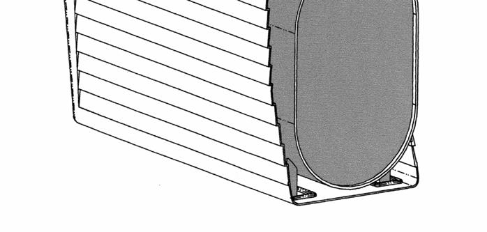
6 STEP 4 PIPING TANK (Diagram A) (Picture 1) It is suggested to pipe the fill & vent out the side of the lid, however the piping may be left inside if preferred. If piping both the fill and vent out through the lid, pipe them so that they exit on the same side. This enables you to lift from the opposite end and view inside the tub without disturbing any piping. FOR FILL LINE: Use (2) 2 Street Elbows to make swing joint on the outermost tank tapping. Install 24 nipple to extend beyond containment basin FOR VENT LINE: Install 2 vent alarm in next tapping then (1) 2 Street Elbow. Install 6 nipple, to extend the vent piping behind the fill joint. Install 2 elbow. Install 36 nipple (or combination of nipples and couplings) to extend vent line beyond containment. FOR BEST FIT DO NOT USE COMBO VENT, USE THE OEM KING #4517 2x2 Tank Alarm, if using 1 ¼ use vent of choice. STEP 5 INSTALLING OIL LINE (Diagram B) Due to Limited access to the bottom of the tank, the oil line CAN ONLY be pulled from the top of the tank. Drill 5/8 (or appropriate size for your oil line) exit holes into Tub Basin. A template for the location is shown in diagram B and suggested pilot holes are centered on the backside of the basin. Do not drill above this point. Install burner supply / return lines from tank top opening through side holes and route to burner away from heat sources or physical damage. Silicone exit holes for additional water resistance. STEP 6 INSTALLING THE LID (Diagram B) (Picture 1) Using the Center Point alignment dimples located on each end of the Tank Tub lid, Drill out the appropriate fill and vent holes with a 2 ½ hole saw. The piping instructions as described in Diagram A are for installing a 2 fill and 2 vent alarm system, If you choose to install an 1 ¼ vent alarm system, use a 1 ¾ hole saw and change all fittings to 1 ¼. From the gasket kit, take the appropriate (O-Rings) and slide them on the fill and vent pipes Pipe both the fill and vent first beyond the basin outer lip and then hook the cover over the fill and vent pipes. Align lid foam supports so that they fit over piping. Now that the cover is in position, from under the lid, slide the (O-Rings) to the outlet were the piping meets the Tub lid. To keep water from entering in fill and vent holes, slide on the appropriate flat gaskets on fill and vent pipes (If water manages to reach behind these seals it will drain out the drip holes in the lid flange.) 6


7 INSTALLATION DIAGRAM 2 VENT PIPE INSTALLATION 2 VENT ALARM 2 STREET ELBOW 6 NIPPLE 2 ELBOW 2 x 36 NIPPLE CHANGE ALL 2 to 1-1/4 FOR 1-1/4 VENT SYSTEM FILL PIPE INSTALLATION 2 STREET ELBOW SECOND 2 STREET ELBOW 2 x 24 NIPPLE. Diagram A Due to variations in tanks, pipe the fill and vent from the side of your tank with the shortest distance to the first tapping. OIL LINE INSTALLATION USE THE FACTORY DRILLED PILOT HOLES AS A GUIDE AND DRILL 2-5/8 HOLES INTO BASIN FOR OIL LINE EXIT Diagram B Placement of (O-Rings) Underneath the lid & as close to the lid opening as possible Placement of the Flat Gaskets outside the lid Conduit Lid Supports Tub Picture 1 Tub Picture 2 2 Foam Lid Supports 7
8 TANK MATE Custom Oil Tank Cover Purpose: To improve the efficiency and appearance of a 275 gallon storage tank Design: 4 Sided Single Piece unit covers and protects a 275 gallon storage tank Shingled roof and vinyl siding design improve the appearance of a storage tank Fill and Vent pilot holes assist in a trouble-free installation Included Accessory kit provides access to bottom tank drain and tank gauge sight glass Additional Information: Vacuum formed from PAXON high density polyethylene Impact brittleness temperature (-76 Degrees Celsius 105 Degrees Fahrenheit) Softening temperature (123 Degrees Celsius 254 Degrees Fahrenheit) Available in white To accommodate taller retrofit applications the Tank Mate can be installed with the Tank Step (sold separately) The Tank Back is available for a free standing installation (sold separately) Tank Stakes are available for custom installations (sold separately) 8
9 Product Specs
10 Installation Instructions IMPORTANT: CONSULT LOCAL CODES FOR INSTALLATION AND USE OF THIS PRODUCT. IN THE ABSENCE OF SUCH LOCAL CODE REQUIREMENTS, THE FOLLOWING ARE MINIMUM RECOMMENDED INSTALLATION AND USE GUIDELINES. THIS PRODUCT IS INTENDED TO PROVIDE TEMPORARY PHYSICAL PROTECTION TO LISTED UL 142 STEEL PRIMARY TANKS FOR OIL BURNER FUEL (#2 FUEL OIL OR EQUIVALENT) OF MAX 275 GAL. OTHER USES OF THIS PRODUCT HAVE NOT BEEN EVALUATED. INCLUDED: (1) Tank Mate Cover & Accessory Kit REQUIRED INSTALLATION SPECS: (both below are for a 2 Fill installation) For 1 ¼ Vent System: (4) 1 ¼ x 6 Tank Legs (2) 2 ST Elbows (1) 2 x 18 Black Nipples (2) 1 ¼ ST Elbows (1) 1 ¼ x 18 Black Nipple - Fill Box and Vent set up For 2 Vent System: (4) 1 ¼ x 4 Tank Legs and recommend oil lines exit from top of tank (4) 2 ST Elbows (2) 2 x 18 Black Nipples - Fill box and Vent set up Choose a location that is at least 10 ft from property lines and 5 ft from any public way Vent pipe, once through cover, must terminate at least 2 ft from any building opening Surface must be level and capable of supporting the cover and full oil tank A CEMENT SLAB IS SUGGESTED APPROX 78 x 36 CALL toll free 1(877) 4 TANKMATE for our suggested custom slab dimensions Do not install in areas which block an exit, could flood or might subject the cover to excessive physical abuse FOR PROPER FIT, TANK SHOULD BE INSTALLED NO FURTHER THAN 2 FROM HOUSE IMPORTANT: IF USING A 2 VENT ALARM - SET UP TANK ON ONLY 4 TANK LEGS IF USING A 1 ¼ VENT ALARM - SET UP TANK ON LEGS 6 OR LESS If existing tank is being used and the tank is on tank legs over 4 or 6 in length, the TANK STEP (sold separately) can be quickly installed to increase the height of the cover 8 and allow for a retrofit installation on a tank with up to 12 tank legs. Do not place damaged or leaking tanks in service Remove screws from Tank Mate and discard wood furring strips Drill out fill and vent holes with a saw larger then pipe for easy assembly - DRILL 1 BELOW PILOT HOLE 10
11 INSTALLATION STEPS 1. For Fill Pipe begin by inserting 2 STREET ELBOW to first or last tapping in tank 2. Pipe a second 2 STREET ELBOW to complete swing joint (ANGLE SWING JOINTS TOWARDS HOUSE OR BACK OF TANK) 3. Install 2 VENT ALARM in opposite end of tank. 4. Insert 2 STREET ELBOW to vent alarm and then add second 2 STEET ELBOW to complete swing joint 5. Attach one 2 x 18 Black nipple to Fill Street Elbow and then hook the Tank Mate onto it 6. Position cover and install fill box 7. Insert 2 x 18 Black nipple through drilled hole for vent pipe and thread to 2 street elbow 8. Install 2 Elbow and nipple then vent cap 9. For finishing steps open the accessory kit and install soffet vents and cosmetic screw covers ANGLE SWING JOINTS TOWARDS HOUSE SHOWN WITH OPTIONAL CONTAINMENT FOR OPTIONAL SITE HOLE USE 3 HOLE SAW AND DRILL HOLE 21 TO CENTER FROM BACK EDGE OF COVER. (INSTALL 3 SOFFET VENT INCLUDED IN ACCESSORY KIT.) OTIONAL VENT HOLE FOR TANK DRAIN (INSTALL 4 SOFFET VENT INCLUDED IN ACCESSORY KIT) DRILL 4 HOLE 16 FROM BACK EDGE OF COVER 11

12 Installation Instructions ACCESSORY KIT INCLUDES 1-3 VENT FOR TANK GUAGE SITE HOLE AND 1-4 VENT FOR TANK PLUG ACESS 9 SCREW CAPS USED WHEN COVER IS ATTACHED TO HOUSE OR TANKBACK FOR OPTIONAL SITE HOLE USE 3 HOLE SAW AND DRILL HOLE 21 TO CENTER FROM BACK EDGE OF COVER. (INSTALL 3 SOFFET VENT INCLUDED IN ACCESSORY KIT.) SHOWN WITH OPTIONAL CONTAINMENT OPTIONAL VENT HOLE FOR TANK DRAIN (INSTALL 4 SOFFET VENT INCLUDED IN ACCESSORY KIT) DRILL 4 HOLE 16 FROM BACK EDGE OF COVER 12


")
13 Installation Instructions 1. ASSEMBLE STEP ON SOFT MATERIAL OR GRASS TO AVOID SCRATCHING COVER ON STEP 3 LAY OUT PARTS 2. TOP EDGE LEFT SIDE LEAVE APROX: 2 OVERHANG CLIP MOULDING INTO POSITION ALONG TOP EDGE OF STEP 3. NOTE TAPE LOCATIONS FOR THE FINAL STEP, PLACE COVER ON ITS FACE (OSS SERIAL # DOWN) SOMEWHERE SOFT, IT WILL SCRATCH ATTACH STEP AND USE INCLUDED FOIL TAPE TO SECURE INTO PLACE. STAND THE COVER BACK UP INTO POSITON AND CONTINUE WITH TANK MATE INSTALLATION. TAPE HOLDS NO PURPOSE AFTER INSTALLATION COMPLETION 13

14 25 Gallon Containment for 275 Gallon Vertical Tanks NEW ADJUSTABLE FLAT STEEL PLATES Avoid any damages from tank or oil line leaks with TANK TRAY. To be used with all inside installations or out doors when used with our TANKMATE Custom Tank Cover. Easy to install with new or existing oil tanks. Made of High Density Polyethylene and aluminum stress supports

15 Installation Instructions BEFORE PLACING TANK IN TRAY 1. Install on cement floor similar flat surface. 2. Place the TANK TRAY in its final installation location. 3. To ensure proper fit, tank legs should be installed without circulator flanges WHEN PLACING TANK IN TRAY Move steel plates under tank legs WHEN INSTALLING TRAY UNDER TANK MATE 1. To allow for height of tray, use ½ shorter tank legs then suggested in TANK MATE installation instructions. 2. Leave 1 between the TANK TRAY and house. This will prevent water flowing down the side of the house to enter into the tray. 3. Optional: For water tight installation, silicone TANK MATE to house. 15


16 AVOID ENVIRONMENTAL DISASTERS AND EXPENSIVE OIL CLEANUP Oil Leak Detection Alarm Consider the confident solution you can offer your customer with a Tank Tray equipped with the Tank Alarm as part of the installation. You are securing your customers confidence in oil heat and giving oil heat the safe image it deserves. FEATURES: LOUD 85 db BUZZER SOUNDS FOR UP TO 3 DAYS INTERMITTEN CHIRP SIGNALS LOW BATTERY CONVENIENT SELF-TEST BUTTON OIL TANK LEG SOUNDING UNIT ALARM SWITCH Tank Tray Use with One Alarm Sensor Tank Pan Use with Two alarm sensors (Additional sensor sold separately) 16


17 TANK STAKE KIT New From Oil Storage Solutions USE THE NEW TANK STAKE KIT AND YOU CAN QUICK RELEASE THE COVER FOR COMPLETE ACCESS TO TANK AND AVOID SCREWING THE COVER TO THE HOUSE Included Parts: 2 Galvanized steel stakes: 2 Zinc coated pins * Parts Needed: 7/16 Drill Bit and a 1. Complete Tank Mate Installation as per Tank Mate Installation Instructions and suggestions at bottom of page. 2. Using a 7/16 Drill bit, drill a hole in the Tank Mate Flange approximately 3 From the bottom. 3. Insert approximately ¾ of the stake into the ground. 4. Insert the looped end of the cable through the drilled hole and fasten the enclosed pin to secure the cable to the cover. 5. Continue to place the stake in the ground until the cover is secure Follow the Tank Mate installation instructions except: Cover Swings Open Install both the Fill and Vent out of the same side of the cover. The Second hole is not pre-dimpled, so mark a pilot hole for your drill 6 further towards the back and on the same plane from the given dimple. To ensure that the cover will swing on both the fill and vent pipes, make both holes with a 3 hole saw. The installation will require the nipples described in the diagram below. If both pipes are brought out the same side of the cover, it is recommended that the cover is made secure by installing our Tank Mate Stake Kit. 30 INCH VENT NIPPLE 18 INCH FILL 6 INCH 17
18 LIMITED WARRANTY Oil Storage Solutions oil tank shed and spill containment product line CONSUMER INFORMATION / CERTIFICATE OF WARRANTY 1. LIMITED 12 YEAR WARRANTY ON ALL TANK MATE / TANK TUB PARTS Oil Storage Solutions hereby warrants the Tank Mate / Tank Tub shed when properly registered with our factory at the time of purchase (as set forth below) to be free from defects in material or workmanship to the original user for the first six (6) years of this warranty. Oil Storage Solutions will repair or, at its option, replace the component part under the conditions explained in paragraph 5, hereof. 2. ADDITIONAL LIMITED WARRANTY Oil Storage Solutions further warrants to the original user of the Tank Mate / Tank Tub, that upon expiration of the first six (6) years of this warranty as set forth above, we will furnish a replacement Tank Mate / Tank Tub upon payment by the original user of a percentage of the suggested retail price at the suggested retail price at time of replacement as set forth in the following schedule: Within 6th through 7th year 60% Within 8th through 9th year 70% Within 10th through 11th year 80% Within 12th year 90% 3. LIMITED 5 YEAR WARRANTY ON ALL TANK TRAY / TANK PAN / TANK STEP / TANK BACK PARTS Oil Storage Solutions hereby warrants the Tank Tray / Tank Pan / Tank Step / Tank Back products when properly registered with our factory at the time of purchase (as set forth below) to be free from defects in material or workmanship. Oil Storage Solutions will repair or, at its option, replace the component part under the conditions explained in paragraph 4, hereof. 4. LIMITED 2 YR WARRANTY ON TANK ALARM PARTS Oil Storage Solutions hereby warrants the Tank Alarm product when properly registered with our factory at the time of purchase (as set forth below) to be free from defects in material or workmanship. Oil Storage Solutions will repair or, at its option, replace the component part under the condition explained in paragraph 5, hereof. 5. EXCLUSIONS AND LIMITATIONS-OIL STORAGE SOLUTIONS SHALL NOT BE LIABLE FOR ANY SPECIAL, INDIRECT, INCIDENTAL OR CONSEQUENTIAL DAMAGES whether arising out of breach of warranty, breach of contract or otherwise. Some states do not allow the exclusion or limitation of incidental or consequential damages, so the forgoing limitation or exclusion may not apply to you. ALL THE WARRANTIES IMPLIED BY STATE LAW, INCLUDING WARRANTIES OF MERCHANTABILITY AND FITNESS FOR A PARTICULAR PURPOSE, ARE HEREBY EXPRESSLY LIMITED TO THE DURATION OF THE LIMITED 12 YEAR WARRANTY SET FORTH. Some states do not allow limitation on how long an implied warranty lasts, so the above limitation may not apply to you. 5. Continued. THIS WARRANTY IS NOT TRANSFERABLE AND SHALL APPLY ONLY IF THE OIL STORAGE SOLUTIONS MANUFACTURED PRODUCT, a) Is correctly installed to the installation instructions contained in the installation instructions provided with the units; and b) Was installed for the intended purpose as described in the installation instructions provided with the units. 6. SHIPPING ASSEMBLY INSTALLATION Any and all costs required to disassemble, remove, ship, reassemble and reinstall a Tank Mate / Tank Tub or part there of ART NOT COVERED under this warranty and shall be borne by original user. 7. THIS WARRANTY IS VOID AND DOES NOT APPLY TO OR LIMITED TO a) The failure or malfunction occurs on a component of the tank or tank fitting which is not solely manufactured by Oil Storage Solutions b) Discoloration of material c) The Material s paintability 8. GENERAL PROVISIONS The original user must notify Oil Storage Solutions 1432 Wantagh Ave. Wantagh, NY 11793, of the defect and or leak promptly after its discovery and within the warranty period in order to obtain service under this warranty. This notification must include the user s name, address and the serial number of the Tank Mate or Tank Tub and proof of purchase. If the original user cannot provide proof of purchase, the warranty shall begin from the date of manufacture as indicated by serial number. Any replacement under this Limited Warranty shall only carry a warranty for unexpired portion of the original warranty. In order to gain coverage under this warranty the consumer is required to fill out and mail the included warranty registration within thirty (30) days of purchase. THIS EXPRESS WARRANTY IS MADE IN LIEU OF ALL OTHER WARRANTIES, GUARANTEES, AGREEMENTS, AND SIMILAR OBILIGATION OF MANUFACTURER WITH RESPECT TO THE REPAIR OR REPLACEMENT OF ANY SAME OR SIMILAR PRODUCT. OIL STORAGE SOLUTIONS NEITHER ASSUMES NOR AUTHORIZES ANY OTHER PERSON TO ASSUME FOR IT AND OTHER LIABILITY IN CONNECTION WITH THE SALE OF ITS PRODUCT. Any and all descriptions, specifications, instructions, drawings, samples or models furnished to the original user do not constitute express warranties. This is our exclusive written warranty. It gives you specific legal rights, but you may also have other rights which very from state to state. 2004/
19 19
FW-RA-LED Remote Multiplex Annunciator Panels
 FW-RA-LED Remote Multiplex Annunciator Panels WIRING and INSTALLATION INSTRUCTION LNOTICE All information, documentation, and specifications contained in this manual are subject to change without prior
Model CV-1FR Riser Check Valves 2 to 12 Inch (DN50 to DN300) General Description. Installation. Technical Data. Page 1 of 6 OCTOBER 2010 TFP950
 General Description. Installation. Technical Data. Page 1 of 6 OCTOBER 2010 TFP950") Technical Services 00--9 +-0--0 www.tyco-fire.com Model CV-FR Riser Check Valves to Inch (DN0 to DN00) General Description The TYCO Model CV-FR Riser Check Valve is a compact and rugged swingtype unit
Technical Services 00--9 +-0--0 www.tyco-fire.com Model CV-FR Riser Check Valves to Inch (DN0 to DN00) General Description The TYCO Model CV-FR Riser Check Valve is a compact and rugged swingtype unit
CD6102 / CD6102 OC / CD6102-2
 PreView Display CD6102 / CD6102 OC / CD6102-2 Operating Manual www.previewradar.com PATENTS Patented under one or more of the following U.S. Patents: 5345471, 5523760, 5457394, 5465094, 5512834, 5521600,
Horizontal Bottle Cooler Installation and Operation Manual
 Speeds Up the Pace of Innovation Horizontal Bottle Cooler Installation and Operation Manual Please read this manual completely before attempting to install or operate this equipment! TBC-50SD, 50SB/ TBC-95SD,
Please Read and Save These Instructions.
 Page 1 of 8 RadonAway Ward Hill, MA. GP500 Fan Installation Instructions Please Read and Save These Instructions. DO NOT CONNECT POWER SUPPLY UNTIL FAN IS COMPLETELY INSTALLED. MAKE SURE ELECTRICAL SERVICE
RP, GP, XP Pro Series Installation Instructions
 RP, GP, XP Pro Series Installation Instructions IN095 Rev B 0718 3 Saber Way, Ward Hill, MA 01835 radonaway.com 1 Fan Installation & Operating Instructions RP, GP, XP Series Fans Please Read and Save These
RIGA ZUHNE
 RIGA 33 33in x 19 1 2 in x 10in 1-855-55-ZUHNE www.zuhne.com info@zuhne.com Fig.1 PRODUCT DESCRIPTION Premium grade handmade sink 16 gauge Stainless Steel T304 10mm/0.4inch radius coved corners Best-in-breed
INSTALLATION AND OPERATION INSTRUCTIONS
 Printed in U.S.A. INSTALLATION AND OPERATION INSTRUCTIONS RFPA21A CONSTRUCTION HEATER FLOOR MODEL SAVE FOR FUTURE REFERENCE Space-Ray Division, Gas Fired Products, Inc. P.O. Box 36485, Charlotte, NC 28236
MODENA ZUHNE
 MODENA 28 28in x 18in x 10in 1-855-55-ZUHNE www.zuhne.com info@zuhne.com 16" 18" 10" PRODUCT DESCRIPTION Premium grade handmade sink 16 gauge Stainless Steel T304 10mm/0.4inch radius coved corners Best-in-breed
RR-PM1200 OPERATING AND PROGRAMMING GUIDE
 ALARM LOCK RR-PM1200 OPERATING AND PROGRAMMING GUIDE ALARM LOCK 2000 OI261 08/00 1 INTRODUCTION The Alarm Lock Remote Release PowerMag is an innovative 1200 lb. electromagnetic locking system with infrared
INTERMEDIATE GUIDE BRACKET
 BAIL ASSEMBLY AND CHAIN TOP RAIL SUPPORT SIDE MOUNT RAIL SUPPORT INTERMEDIATE GUIDE BRACKET LIFT-OUT RAIL SYSTEM 4" & 6" LIFT-OUT RAIL SYSTEMS INSTALLATION MANUAL WITH REPAIR PARTS LIST NOTE! To the installer:
Model A Pipe Line Strainer 3, 4, 6, 8 & 10 Inch (DN80, DN100, DN150, DN200 & DN250) 175 psi (12,1 bar) General Description.
 175 psi (12,1 bar) General Description.") Technical Services: Tel: (00) 31-9312 / Fax: (00) 91-5500 Customer Service/Sales: Tel: (1) 50-5000 / (00) 55-523 Fax: (1) 50-5010 / (00) -1295 Model A Pipe Line Strainer 3,,, & 10 Inch (DN0, DN100,, DN200
Technical Services: Tel: (00) 31-9312 / Fax: (00) 91-5500 Customer Service/Sales: Tel: (1) 50-5000 / (00) 55-523 Fax: (1) 50-5010 / (00) -1295 Model A Pipe Line Strainer 3,,, & 10 Inch (DN0, DN100,, DN200
Use and Care Manual VERONA 32 OM 16 GAUGE STAINLESS STEEL SINGLE BOWL OVERMOUNT SINK ZUHNE
 Use and Care Manual VERONA 32 OM 16 GAUGE STAINLESS STEEL SINGLE BOWL OVERMOUNT SINK 1 855 55 ZUHNE www.zuhne.com info@zuhne.com 22.01" 16.54" 9.02" 3.90" 29.84" 32.99" Fig.1 PRODUCT DESCRIPTION Premium
IN020 Rev F Page 1 of 8
 IN020 Rev F Page 1 of 8 RadonAway Ward Hill, MA. Series Fan Installation Instructions Please Read and Save These Instructions. DO NOT CONNECT POWER SUPPLY UNTIL FAN IS COMPLETELY INSTALLED. MAKE SURE ELECTRICAL
OCH-SS series Direct Wired Units Indoor * and Outdoor Comfort Heaters
 1200 North Main Street Fostoria, OH 44830 Phone: 800-495-4525 Fax: 419-435-0842 A DIVISION OF www.fostoriaindustries.com OCH-SS series Direct Wired Units Indoor * and Outdoor Comfort Heaters *EXCLUDING
CWR265SZ 26 Bottle Built-in Wine Cooler Owner s Manual
 CWR265SZ 26 Bottle Built-in Wine Cooler Owner s Manual This owner s manual provides instructions on safe installation use, and troubleshooting assistance. Please read it carefully and save it for reference
nova extreme retrofit High Output T5 Lighting Kit
 nova extreme retrofit High Output T5 Lighting Kit Instructions for Model Nova Extreme Retrofit Model#1130-1135 Important Safety Instructions... Page 2 Installation Instructions... Page 4 Warranty... Page
INSTALLATION AND OPERATING MANUAL
 dickinson since 1932 MODEL 00-NEW-P12000 INSTALLATION AND OPERATING MANUAL Manufactured by: Dickinson Marine (1997) Ltd, 407-204 Cayer Street, Coquitlam, British Columbia, Canada V3K 5B1 www.ahoycaptain.com
Installation Instructions
 Installation Instructions Type B Gas Vent Model E/R 3" 8" ECCO TYPE B GAS VENT AND ACCESSORIES ARE FOR USE ONLY WITH LISTED CATEGORY 1 GAS-FIRED APPLIANCES OR APPLIANCES LISTED FOR USE WITH TYPE B GAS
Please Read And Save These Instructions.
 RadonAway Ward Hill, MA XP/GP/XR Series Fan Installation Instructions Please Read And Save These Instructions. DO NOT CONNECT POWER SUPPLY UNTIL FAN IS COMPLETELY INSTALLED. MAKE SURE ELECTRICAL SERVICE
SEISCO SUPERCHARGER EXTENDER/BOOSTER INSTALLATION GUIDE & OWNERS MANUAL
 SEISCO SUPERCHARGER EXTENDER/BOOSTER INSTALLATION GUIDE & OWNERS MANUAL This manual is provided as a guide to installation. All installations must comply with any and all local and national electrical
WKS 4000 SERIES (USA only) --INSTALLATION INSTRUCTIONS--
 --INSTALLATION INSTRUCTIONS--") 8610 Production Avenue San Diego, California 92121 (858) 566-7465 Fax (858) 566-1943 WKS 4000 SERIES (USA only) --INSTALLATION INSTRUCTIONS-- Thank you for choosing a BREEZAIRE cooling unit. We believe
8610 Production Avenue San Diego, California 92121 (858) 566-7465 Fax (858) 566-1943 WKS 4000 SERIES (USA only) --INSTALLATION INSTRUCTIONS-- Thank you for choosing a BREEZAIRE cooling unit. We believe
14 Upright Vacuum with HEPA Filter & Dual Power
 E29990-00 14 Upright Vacuum with HEPA Filter & Dual Power Operator and Parts Manual 1001 Brown Avenue Toledo, Ohio 43607-0127 Customer Service: 888-GO-BETCO Fax: 800-445-5056 Technical Service: 877-856-5954
TORRID MARINE YACHT QUALITY Since Owner s Manual
 Marine Water Heaters Owner s Manual Plumbing Configuration Note: While Torrid Marine is always happy to offer advice, we highly recommend you choose a professional marine technician to install your new
 PROBLEM POSSIBLE CAUSES SOLUTIONS The motor seems to run too much The lights do not work High efficiency compressor and fans The room or outdoor temperature is hot A large amount of warm food has been
XT Series Thermostats
 ISO 9001 Explosion-Proof & Moisture Resistant XT Series Thermostats Installation, Operation, & Maintenance Instructions XTWA Thermostat XTWL Thermostat XTB Thermostat Part No.MI133.Rev.2.00 Date of Issue:
Use/Installation Guide
 Use/Installation Guide Outdoor Stainless Steel Cabinets IMPORTANT - PLEASE READ AND FOLLOW Before beginning, please read these instructions completely and carefully. Do not remove permanently affixed labels,
INSTRUCTIONS PARTS LIST For President, Monark, Standard, and Fast-Flo Pumps, and Agitator
 INSTRUCTIONS PARTS LIST 308 466 KEEP FOR REFERENCE STAINLESS STEEL, PASSIVATED Drum Covers Part No. 37 306 Drum Cover, Series A For President, Monark, Standard, and Fast-Flo Pumps, and 06 758 Agitator
Carbon Monoxide (CO) Detecting Ventilation Fan Controller Model 120VC Single Relay (100/25 PPM) (200/35 PPM)
 Detecting Ventilation Fan Controller Model 120VC Single Relay (100/25 PPM) (200/35 PPM)") Carbon Monoxide (CO) Detecting Ventilation Fan Controller Model 120VC Single Relay 905-0005-01 (100/25 PPM) 905-0005-02 (200/35 PPM) 1. INTRODUCTION Your COSTAR VC carbon monoxide detecting ventilation
Carbon Monoxide (CO) Detecting Ventilation Fan Controller Model 120VC Single Relay 905-0005-01 (100/25 PPM) 905-0005-02 (200/35 PPM) 1. INTRODUCTION Your COSTAR VC carbon monoxide detecting ventilation
Thermometer model 02059
 Instruction Manual Thermometer model 02059 pm CONTENTS Unpacking Instructions... 2 Package Contents... 2 Product Registration... 2 Features & Benefits: Sensor... 2 Features & Benefits: Display... 3 Setup...
Ui REFRIGERATOR SPEC SHEET
 Ui REFRIGERATOR SPEC SHEET ISOMETRIC VIEW 19 7/8 20 1/2 32 3/4 FRONT VIEW NOTES: 1. CUTOUT DIMENSIONS: 20 1/2"W X 33"L X 20 3/4"D 2. CUTOUT DIMENSIONS ARE FOR REFRIGERATOR ONLY. REFER TO STAINLESS STEEL
AirScape Solar Attic Fan. Installation Manual SAF10R SAF25R
 AirScape Solar Attic Fan Installation Manual SAF10R SAF25R Thank you for purchasing the AirScape Solar Attic Fan. Please take the time to read through the entire instructions prior to starting any work.
INSTRUCTION MANUAL HS-229G
 INSTRUCTION MANUAL HS-229G 510977 STEP 1 - Where to Install the Thermostatic Steam Trap Determine where to install the thermostatic steam trap based on the following information. a. The trap should be
Users Manual. LAURUS Systems, Inc. - Ph: Fax:
 Users Manual LAURUS Systems, Inc. - Ph: 410-465-5558 - Fax: 410-465-5257 - www.laurussystems.com Introduction The rad-d is a security and inspection system that detects emissions from radioactive material.
Thermostat Series. Installation Manual TSTBM-RRS--TW-A Revised 02-13
 Installation Manual Thermostat Series TSTBM-RRS--TW-A Remote Temperature Sensor (Requires TSTBM3H2CPH6W-A) TSTBM-RRS--TW-A 2 TSTBM-RRS--TW-A Table Of Contents Table of Contents Thermostat Quick Reference...
INSTALLATION INSTRUCTIONS. Cubix Widespread Faucet Part #: 3204, 5204, 3304, 5304 HANDLE STYLES
 INSTALLATION INSTRUCTIONS Cubix Widespread Faucet Part #: 04, 04, 04, 04 Confidence from start to finish. HANDLE STYLES 04 04 jaclo industries Dermody Street Cranford, NJ 001 p 0..44 00..0 f 0..11 00..4..1
DECORATIVE GAS LOG PLACEMENT INSTRUCTIONS
 DECORATIVE GAS LOG PLACEMENT INSTRUCTIONS REVOLUTION L-360-CD & L-420-CD SERIES If for any reason, you cannot follow these instructions, FOR ANY REASON WHATSOEVER, just return the product to your dealer,
ECCOTEMP. Point of Use Tankless Water Heaters EP-2.4 / EP-7.0. Installation and Operating Instruction Manual. Shop Online.
 ECCOTEMP Point of Use Tankless Water Heaters EP-2.4 / EP-7.0 Installation and Operating Instruction Manual Product Support Eccotemp.com/help-desk Shop Online Eccotemp.com/products Store Locator Eccotemp.com/locator
SF180 Installation Instructions
 SF180 Installation Instructions 1 Fan Installation & Operating Instructions Please Read and Save These Instructions. DO NOT CONNECT POWER SUPPLY UNTIL FAN IS COMPLETELY INSTALLED. MAKE SURE ELECTRICAL
Professional Warming Drawer and Warming Drawer Cabinet
 Professional Warming Drawer and Warming Drawer Cabinet Care & Use/Installation Instructions Models: (C)VQEWD5300SS (C)VQEWD5420SS IMPORTANT SAFETY INSTRUCTIONS WARNING: Read this manual carefully and completely
Turbo Air Speed up the Pace of Innovation TBB-4SB CAUTION! PLEASE KEEP POWER SWITCH ON BEFORE OPERATING THIS EQUIPMENT
 Turbo Air Speed up the Pace of Innovation CAUTION! PLEASE KEEP POWER SWITCH ON BEFORE OPERATING THIS EQUIPMENT Underbar Equipment Back Bars Installation and Operation Manual Please read this manual completely
OWNER S GUIDE. Electrolux Precision. Steam
 OWNER S GUIDE Electrolux Precision Steam Introduction Congratulations on your purchase of an Electrolux steam mop designed to help you care for your home environment. This Owner s Guide will help you make
ALL-WEATHER LANDSCAPE BURIAL SUBWOOFERS Burial Subwoofers: 10 & 12 (250mm & 300mm)
") ALL-WEATHER LANDSCAPE BURIAL SUBWOOFERS Burial Subwoofers: 10 & 12 (250mm & 300mm) CONTENTS 10 Burial Subwoofer: (1) Burial Subwoofer with Direct Burial Cable Attached (2) Silicone-Filled Wire Connectors
ALL-WEATHER LANDSCAPE BURIAL SUBWOOFERS Burial Subwoofers: 10 & 12 (250mm & 300mm) CONTENTS 10 Burial Subwoofer: (1) Burial Subwoofer with Direct Burial Cable Attached (2) Silicone-Filled Wire Connectors
IN-GROUND SUBWOOFER INSTRUCTION MANUAL LS12T SUB LS15T SUB
 IN-GROUND SUBWOOFER INSTRUCTION MANUAL LS12T SUB LS15T SUB Introduction Thank you for purchasing a SLS Subwoofer. When properly installed, this subwoofer will provide you with years of outdoor entertainment
OWNE R S MA N UA L. Made in USA. September 2015
 September 2015 OWNE R S MA N UA L Made in USA www.drinkableair.com OWNER S MANUAL Warranty 02 Atmospheric Water Generators (AWGs) 03 Safety Precautions 04 Operational Diagram & System Specs 05 Getting
 If you experience The refrigerator is noisy The door will not close completely The door is difficult to open Temperature is too warm There is interior moisture buildup NOTE: Some moisture buildup is normal.
A PROUD HERITAGE OF EXPERIENCE & QUALITY. Beverage Cooler VT-SC-1
 A PROUD HERITAGE OF EXPERIENCE & QUALITY Beverage Cooler VT-SC-1 O W N E R S M A N U A L W W W. V I N O T E M P. C O M Your Beverage Cooler This unit can be used for Storage and/or Service. The cooler
Here is what comes in your box:
 Here is what comes in your box: We recommend that you pull everything out of the box and lay it out. We have grouped the drawn components below with the hardware you ll need for those parts. The screws
Please Read and Save These Instructions Safety Information
 The learning fan TM Please Read and Save These Instructions Safety Information 1.) WARNING - TO REDUCE THE RISK OF FIRE, ELECTRIC SHOCK, OR INJURY TO PERSONS, OBSERVE THE FOLLOWING: a) Installation work
ALL WEATHER SL-SERIES QUARTZ TUBE ELECTRIC INFRARED RADIANT HEATER INSTALLATION USE & CARE MANUAL
 ALL WEATHER SL-SERIES QUARTZ TUBE ELECTRIC INFRARED RADIANT HEATER TABLE OF CONTENTS: INSTALLATION USE & CARE MANUAL IMPORTANT INFORMATION Assembly Instructions 2 Wiring Instructions 2 Outdoor Installation
Warnings 2. Installation Instructions 3. Wiring Instructions 3. Mounting Instructions 4-5. Replacement Element Installation 5. Replacement Parts 5-6
 TABLE OF CONTENTS Warnings 2 Installation Instructions 3 Wiring Instructions 3 Mounting Instructions 4-5 Replacement Element Installation 5 Replacement Parts 5-6 Heater Coverage Areas 6 General Notes 6
Corn Flame Energy Corn Stove Model 3000
 Corn Flame Energy Corn Stove Model 3000 Installation and Operation Guide Read thoroughly before starting installation Save this manual for future reference SAFETY NOTICE If this stove is not properly installed,
Section 1 - Safety Information Section 2 - Installation: Wall Mount Hoods Section 3 - Installation: Island Mount Hoods
 Range Hoods Owner s Manual Section 1 - Safety Information Section 2 - Installation: Wall Mount Hoods Section 3 - Installation: Island Mount Hoods Section 4 - Use & Care Instructions Section 5 - Control
HS Series Installation & Operating Instructions RadonAway
 The World s Leading Radon Fan Manufacturer HS Series Installation & Operating Instructions RadonAway 3 Saber Way Ward Hill, MA 01835 www.radonaway.com P/N IN007-REV K 10/15 RadonAway Ward Hill, MA. HS
Getz Equipment Innovators 450 lb Dual Portable Dry Chemical Fill System
 Getz Equipment Innovators 450 lb Dual Portable Dry Chemical Fill System 1 Revised 11/18/10 2320 Lakecrest Drive, Pekin IL 61554 PH. (888) 747-4389 Fax (309) 495-0625 Website: www.getzequipment.com LIMITED
MaxLite Polygon Linear LED Light
 General Safety Information For Contractors: WARNING: Light fixtures should only be installed by qualified electricians. Be sure to use proper mounting method and hardware rated for the weight of the light
INSTALLATION USE & CARE MANUAL ALL WEATHER SL-SERIES QUARTZ TUBE ELECTRIC INFRARED RADIANT HEATER
 INSTALLATION USE & CARE MANUAL ALL WEATHER SL-SERIES QUARTZ TUBE ELECTRIC INFRARED RADIANT HEATER TABLE OF CONTENTS IMPORTANT INFORMATION Warnings 2 Installation Instructions 3 Wiring Instructions 3 Outdoor
Thermometer with Wired Sensor
 Instruction Manual Thermometer with Wired Sensor model 02042 CONTENTS Unpacking Instructions... 2 Package Contents... 2 Product Registration... 2 Features & Benefits... 3 Setup... 4 Temperature Units...
ILLUSION 11.2 K-factor Extra Large Orifice Concealed Pendent Sprinklers Quick Response, Standard Coverage General Description
 Technical Services: Tel: (800) 381-9312 / Fax: (800) 791-5500 ILLUSION 11.2 K-factor Extra Large Orifice Concealed Pendent Sprinklers Quick Response, Standard Coverage General Description The Tyco ILLUSION,
Installation Instructions / Warranty
 Installation Instructions / Warranty Massaud 18112001 Massaud 18115001 Axor Massaud 3-Hole Lavatory Mixer Trim with Short Spout 18112001 Axor Massaud 3-Hole Lavatory Mixer Trim with Long Spout 18115001
D2E Duct Smoke Detector
 INSTALLATION AND MAINTENANCE INSTRUCTIONS D2E Duct Smoke Detector Specifications Operating Temperature: 20 to 60 C Storage Temperature: 20 to 60 C Humidity: 0% to 93% Relative Humidity Non-condensing Air
Service Parts, Kits and Accessories
 The parts identification guides on the following pages have been designed to give a quick reference to component parts used on pilot ignition agricultural building heaters. The guides identify components
Installation Instructions / Warranty
 Installation Instructions / Warranty Citterio M 34133XX1 Citterio M 34213XX1 Axor Citterio M widespread lavatory faucet 34133XX1 Axor Citterio M widespread bidet faucet 34213XX1 34213XX1 34133XX1 Technical
C L E A N I N G / M A I N T E N A N C E WA R R A N T Y I N F O R M AT I O N CLEANING/MAINTENANCE FAN STORAGE 3 YEAR LIMITED WARRANTY INSTRUCTIONS
 pure indoor living 16-INCH (41 CM) STAND FAN MODEL: BSF1016RT-CN Instruction Leaflet Read instructions before operating. Retain for future reference. Questions? Comments? Call 1-800-253-2764 in North America.
Thermometer with Probe model 00891A
 Instruction Manual Thermometer with Probe model 00891A CONTENTS Unpacking Instructions... 2 Package Contents... 2 Product Registration... 2 Features & Benefits... 3 Setup... 4 Temperature Units... 4 Placement
Owner s Manual.
 Owner s Manual Introduction Features / Benefits Records Specifications Warnings Controls / Diagrams Setting Up the Unit Operating the Unit Maintaining the Unit Safety & Warnings Consumer Information Warranty
WMWLB / WMWFM / WTWLB / WTWFM Series Hydronic Heating Unit
 January 2008 WMWLB / WMWFM / WTWLB / WTWFM Series Hydronic Heating Unit Installation Operation Maintenance The units are designed for permanent up flow, counter flow, or horizontal left or right airflow
September 2016 Humidex GVS-H Rev. 2.2En. Owner s Manual. Manufactured by: Clairitech Innovations Inc Ohio Rd. Boudreau-West, NB Canada E4P 6N4
 September 2016 Humidex GVS-H Rev. 2.2En Owner s Manual Manufactured by: Clairitech Innovations Inc. 1095 Ohio Rd. Boudreau-West, NB Canada E4P 6N4 Table of Contents Table of Contents 1 Service and Warranty
HS Series Installation & Operating Instructions RadonAway
 The World s Leading Radon Fan Manufaturer HS Series Installation & Operating Instructions RadonAway 3 Saber Way Ward Hill, MA 01835 www.radonaway.com P/N IN007-REV J 9/13 RadonAway Ward Hill, MA. HS Series
VENTILATION FAN / LED LIGHT
 VENTILATION FAN / LED LIGHT MODEL ITG50LED/ITG80LED TABLE OF CONTENTS Package Contents General Safety Information Preparation 4 Assembly Instructions 5 New Construction 5 Existing Construction 6 Grille
breeze easytm model # F100-1W
 DewStop breeze easytm model # F100-1W Installation Guide Read and Save These Instructions LISTED Questions, Problems, Missing Parts? Please Call 1-360-876-2974 or E-Mail info@dewstop.com please retain
Warnings 2. Installation Instructions 3. Wiring Instructions 3. Mounting Instructions 4. Replacement Element Installation 5. Replacement Parts 5
 TABLE OF CONTENTS Warnings 2 Installation Instructions 3 Wiring Instructions 3 Mounting Instructions 4 Replacement Element Installation 5 Replacement Parts 5 Heater Coverage Areas 6 General Notes 6 Maintenance
2 INLET / HIGH HEAD DRAIN PUMP SYSTEMS MODELS , INSTALLATION INSTRUCTIONS PREINSTALLATION CHECKLIST
 Your Peace of Mind is Our Top Priority Product information presented here reflects conditions at time of publication. Consult factory regarding discrepancies or inconsistencies. MAIL TO: P.O. BOX 637 Louisville,
OPERATION, SERVICE & PARTS MANUAL
 OPERATION, SERVICE & PARTS MANUAL BROASTER 620N & 621 EASY BREADER Be sure ALL installers read, understand, and have access to this manual at all times. MODEL 620N MODEL 621 Genuine Broaster Chicken, Broasted,
FOR EASY, FAST INSTALLATION AND FOR RESULTS
 Page 1 INSTALLATION & OPERATING INSTRUCTIONS FOR FEDERAL FLOOR FURNACE OFB-100 AND OFB100L UNPACK SHIPMENT CAREFULLY AND INSPECT FOR DAMAGE. ALL GOODS ARE CAREFULLY MANUFACTURED, INSPECTED, CHECKED, AND
EXPANDABLE 0.5W LED FRESHWATER LIGHT FIXTURES
 INSTALLATION & MAINTENANCE GUIDE EXPANDABLE 0.5W LED FRESHWATER LIGHT FIXTURES Item # Product Description 420269 Light 20 IN 0.5W X 8W Freshwater 420270 Light 24 IN 0.5W X 9.6W Freshwater 420271 Light
IAQ Series. Bosch IAQ Photo Catalytic Oxidizer (PCO) Residential Application. Installation Manual and Owner s Guide
 Residential Application. Installation Manual and Owner s Guide") Installation Manual and Owner s Guide IAQ Series Bosch IAQ Photo Catalytic Oxidizer (PCO) Residential Application PCOB-09012-0--A - 9" PCO BULB PCOB-14024-0--A - 14" PCO BULB 67202220344 Revised 07-12
Installation Manual and Owner s Guide IAQ Series Bosch IAQ Photo Catalytic Oxidizer (PCO) Residential Application PCOB-09012-0--A - 9" PCO BULB PCOB-14024-0--A - 14" PCO BULB 67202220344 Revised 07-12
Duct Mount. Installation Instructions
 Duct Mount Installation Instructions 00809-0600-4975 Legal Notice The Flame Detector described in this document is the property of Rosemount. No part of the hardware, software, or documentation may be
SONANCE GARDEN SERIES SGS SYSTEM INSTRUCTION MANUAL
 SONANCE GARDEN SERIES SGS SYSTEM INSTRUCTION MANUAL TABLE OF CONTENTS Design and Features 2 Introduction 2 Box Contents 2 Speaker Layout Planning 2 Types of Wire 3 Speaker Installation 3 Connecting the
Use this product according to this instruction manual. Please keep this instruction manual for future reference. MODELS: ST-H15-B & ST-H30
 273 Branchport Avenue Long Branch, N.J. 07740 (800) 631-2148 Thank you for using our products. www.wheelockinc. com INSTALLATION INSTRUCTIONS HORN SPEAKER WITH MULTI-TAP TRANSFORMER Use this product according
USER GUIDE. Metal Ceramic Heater NS-HTMCSL6. Before using your new product, please read these instructions to prevent any damage.
 USER GUIDE Metal Ceramic Heater NS-HTMCSL6 Before using your new product, please read these instructions to prevent any damage. Contents Insignia Metal Ceramic Heater Introduction.....................................................
EVEN SEAR MULTI GRILL INSTRUCTION MANUAL MODEL: CKCLIG1
 EVEN SEAR MULTI GRILL INSTRUCTION MANUAL MODEL: CKCLIG1 1 TABLE OF CONTENTS IMPORTANT SAFEGUARDS 3 POLARIZED PLUG 4 PRODUCT DIAGRAM 5 USAGE INSTRUCTIONS PREPARING YOUR EVEN SEAR MULTI GRILL 6 HOW TO USE
Introduction. Features. Benefits. Records
 Owner s Manual Introduction Specifications Control Panel / Remote Unit Diagrams Unit Setup & Operation Maintaining the Unit Safety info / Warnings Warranty Information 3 4 5 6 7 8 10 11 Introduction Welcome
3-in-1 Owner s Manual
 3-in-1 Owner s Manual TABLE OF CONTENTS About pureheat 3-in-1....3 Features....3 Specifications...3 Product Contents....4 Warnings...4 Unit Diagram....5 /Remote/LCD Diagrams....6 Unit Setup...7 Using pureheat
VENTILATION FAN / LED LIGHT / LED NIGHT LIGHT
 VENTILATI FAN / LED LIGHT / LED NIGHT LIGHT MODEL REC80LED TABLE OF CTENTS Package Contents General Safety Information 3 Preparation Wiring Diagram 5 Assembly Instructions 6 Care and Maintenance 9 Troubleshooting
Because you re not like everyone else. PORTABLE CLEAR ICE MAKER IM200SS OWNER S MANUAL. Manual v1.0
 Because you re not like everyone else. PORTABLE CLEAR ICE MAKER IM200SS OWNER S MANUAL Manual v1.0 2 BECAUSE YOU RE NOT LIKE EVERYONE ELSE And neither are we. Always at the forefront of our industry, our
Installation and Maintenance "L" and "LS" Series
 Installation and Maintenance "L" and "LS" Series IB-43-E This bulletin should be used by experienced personnel as a guide to the installation and maintenance of "L" and "LS" Series ultra capacity float
Installation Instructions / Warranty
 Installation Instructions / Warranty Metris 31063XX1 Metris 31263XX1 Talis 32310XX1 Focus 31730001 Metris Widespread Lavatory Faucet Metris Widespread Bidet Faucet Talis S Widespread Lavatory Faucet Focus
 Changing the Light Bulb The light bulb is located behind the Temperature control. IMPORTANT: Depending on your model, the light bulb in your new refrigerator may use LED technology. If your model uses
TURBO Fiberglass Cone Fan and Grill Fan 48'' Belt Drive. Installation & Operator s Instruction Manual
 TURBO Fiberglass Cone Fan and Grill Fan 48'' Belt Drive Installation & Operator s Instruction Manual July 1998 MV1383B Chore-Time TURBO TM Fan Extended Warranty Chore-Time Equipment warrants new TURBO
Owner s Manual.
 Owner s Manual Introduction Features / Benefits Records Specifications Warnings Controls / Diagrams Setting Up the Unit Operating the Unit Maintaining the Unit Consumer Information Warranty Information
TS-9 Owner s Manual. Attention! Please Read First!
 TS-9 Owner s Manual Attention! Please Read First! The information in the following manual is important and must be read in full and followed completely for your safety. Table of Contents 1. Diagram Inside
Incinerator Model A1600 -Oil
 Incinerator Model A1600 -Oil Operators Manual Important Failure to cure refractory Before using will void warranty (See refractory curing procedure) Tampering with orifices in the burner will void warranty
MaxLite LED High Bay Fixtures
 General Safety Information To reduce the risk of death, personal injury or property damage from fire, electric shock, falling parts, cuts/abrasions, and other hazards read all warnings and instructions
PORTABLE AIR CONDITIONER OWNER S MANUAL
 PORTABLE AIR CONDITIONER OWNER S MANUAL ASSEMBLY AND OPERATING INSTRUCTIONS MODELS: JHS-A018-10KR SKU#: 130004 JHS-A018-12KRH SKU#: 130005 WARNING: Read and follow all warnings and instructions in this
User Manual. 110 Cup (55 Cup Raw) Gas Rice Cooker. Model: 177GRCLP, 177GRCNAT 12/2018. Please read and keep these instructions. Indoor use only.
 Gas Rice Cooker. Model: 177GRCLP, 177GRCNAT 12/2018. Please read and keep these instructions. Indoor use only.") 110 Cup (55 Cup Raw) Gas Rice Cooker Intertek 5010781 Conforms to ANSI STD Z83.11-2016 Model: 177GRCLP, 177GRCNAT 12/2018 FOR YOUR SAFETY Do not store or use gasoline or other flammable vapors or liquids
110 Cup (55 Cup Raw) Gas Rice Cooker Intertek 5010781 Conforms to ANSI STD Z83.11-2016 Model: 177GRCLP, 177GRCNAT 12/2018 FOR YOUR SAFETY Do not store or use gasoline or other flammable vapors or liquids
User s Manual and Operating Instructions
 User s Manual and Operating Instructions Model Numbers: PT-18W-DDF-A, PT-20F-DDF-A, PT-20S-DDF, PT-24O-DDF, PT-24-DDF, PT-24-DDF-F, PT-30-DDF, PT-30P-DDF-A, PT-30P-DDF-AF READ AND SAVE THESE INSTRUCTIONS
sanctuary walk-in bathtubs PROUDLY BROUGHT TO YOU BY
 Thank you for choosing an Sanctuary Walk In Tub, the world s highest quality walk-in bathtub. Our mission at is to help you maintain independence over your essential bathing needs and to improve your overall
Pre-Fab Easy Installation For Model 0011-CF-USK Installation and Operating Instructions for Existing Homes Or Buildings with Standard Piping
 Instruction Sheet 102-153 Pre-Fab Easy Installation For Model 0011-CF-USK Installation and Operating Instructions for Existing Homes Or Buildings with Standard Piping Plant I.D. 001-1184 EFFECTIVE: June
expandable led Installation & Maintenance Guide Product Description Light 48 IN 21.6W 10K/460nm Expandable Light 36 IN 15W 10K/460nm Expandable
 Installation & Maintenance Guide expandable led Light Fixtures Item # Product Description 420243 Light 24 IN 9.6W 460nm Expandable 420245 Light 36 IN 15W 460nm Expandable 420247 Light 48 IN 21.6W 460nm