INSTALLATION, START-UP AND OPERATION MANUAL
|
|
|
- Hope Goodwin
- 6 years ago
- Views:
Transcription

1 INSTALLATION, START-UP AND OPERATION MANUAL AIR COOLED SCROLL WATER CHILLERS ALY010A ALY080A
2 INDEX PAGE A. GENERAL Introduction 3 Scope of this Manual 3 Safety Consideration & Symbols 3-4 Warranty 5 B. PRODUCT INFORMATION Model designation details 6 Major Features 6 Standard control & Safety devices and other accessories 7 Optional Features 7-8 Physical data 9-10 Microprocessor controller overview 11 C. HANDLING & STORAGE Inspection 12 Rigging Instructions Storage instructions 14 D. INSTALLATION PROCEDURES Pre-installation guidelines 15 Space Requirements Clearances 20 Vibration Isolation and Schematic Mounting Layouts Recommendations for Spring Type Isolator Selection 23 Load distribution (with aluminium fin condenser coils) 24 Load distribution (with copper fin condenser coils) 24 Unit installation 25 Mounting Points Cooler Piping connections Cooler Connection Types 28 Water Requirements 28 Electrical connections, power & control wiring Electrical data 31 Typical schematic wiring diagram 32 Installation Inspection 33 E. START-UP, COMMISSIONING AND OPERATING PROCEDURES General 34 Request for start-up representative 34 Pre-start up requisites 34 Start up of the system 35 Lubrication.. 36 System water flow rate and Pressure drop Ethylene Glycol Solution capacity correction (Antifreeze) 39 Normal operation and cycling 40 Compressor Staging & sequence of operation. 40 Capacity control steps 40 Unit shutdown 41 F. MICROPROCESSOR CONTROLLER DATA Introduction 42 Master compressor board & slave compressor board 42 Use interface board description 42 User sequence of operation 42 Configuration 43 Software control concept 43 Temperature control 44 LCD display data 45 MCH2 Carel Control Alarm code 46 PCO1 Table of Alarms 47 Alarms 48 remote mountoring system 48 1
3 INDEX PAGE MALFUNCTIONS AND CORRECTIVE ACTIONS 49 G. APPENDIX Start-up & commissioning check list Check - out report Preventive Maintenance Schedule 56 Troubleshooter's Guide to Chiller problems Recommended Spare parts 61 Major parts list Material safety data sheet (R-134a) 65 Pressure temperature chart (R-134a) Useful equation and Data Symbols used in chiller plant drawings
4 GENERAL INTRODUCTION ZAMIL Air Conditioner s ALY-Series water chillers are manufactured to provide engineering excellence in comfort air conditioning and industrial cooling with a superior combination of energy saving, performance, application flexibility, ease of service & maintenance, environmental friendliness and ability to withstand extreme ambient temperatures. This manual contains all the information required for correct installation, start-up and commissioning of the units, together with operating instructions. The manual should be read thoroughly before attempting to perform any of the aforesaid tasks and all procedures and instructions detailed in this manual must only be carried out by suitably trained and qualified personnel. The manufacturer will not be liable for any personnel injury or equipment damage caused by incorrect installation, commissioning or operation resulting from a failure to follow and implement the procedures, instructions and recommendations detailed in this manual. SCOPE OF THIS MANUAL The contents of this manual include suggested best working practices and procedures. These are issued for guidance only and they do not supersede governing local safety codes/regulations nor the individual responsibility of the personnel working on these units who shall remain primarily responsible for their own safety and the equipment as well. This manual, and any other documents supplied with the unit, are the sole property of Zamil Air Conditioners, which reserves all rights. They may not be reproduced or distributed in any form or by any means, without prior written permission from Zamil or its representatives. In accordance with our policy for continuous research and product improvement, the information contained in this manual is subject to change without notice. While Zamil makes no commitment to update or provide current information automatically to the manual owner, that information, if applicable, can be obtained by contacting the nearest Zamil or its representative s offices. It is the responsibility of operating/service personnel to verify applicability of this manual to the equipment involved. If they have any doubt with regards to the applicability of this document, then, prior to working on the equipment, they should verify with the owner whether the equipment has been modified/ improved and if current literature is available. SAFETY CONSIDERATIONS & SYMBOLS This equipment is a complex engineering product and the personnel involved during installation, operation, maintenance or service, may be exposed to certain components or conditions including, but not limited to: refrigerants, oils, pressurized components, rotating parts and both high and low voltages. Each of these items has the potential, if misused or handled improperly, to cause injury or death. It is the obligation of operating/service personnel to identify and recognize these inherent hazards, protect themselves and proceed safely in completing their tasks. Failure of the personnel to comply with any of these requirements could result in serious damage to this equipment and the facility, in which it is installed, as well as severe injuries or death to themselves and other people at the site. This manual is intended for use by owner authorized operating/service personnel. It is expected that these personnel are suitably trained and qualified which will enable them to perform their assigned tasks properly and safely. It is essential that prior to performing any task on this equipment, the personnel must have thoroughly read and understood this manual, all tags and stickers on the units and any other applicable documents. These people shall also be cognizant of and comply with all applicable local codes and regulations pertaining to the job on hand. The major safety considerations are as follows and must be exercised during application, installation, start-up and operation of these units: Proper Design & Operation: These chillers are designed for cooling water or glycol solutions and not suitable for purposes other than those specified in our application catalogue. Any misuse of this equipment, may result in injury to the operator or damage to equipment. The units must not be operated beyond the domain of performance data furnished in our application catalogue. Foundation, Support & Isolation: Suitable structural support and vibration isolation must be provided as indicated in these instructions. Failure to do so may result in injury to the operator or damage to the equipment and/or building. 3
5 Discard Intrusions: The units are not designed to bear additional loads or stresses from adjacent equipment, pipework or structures. Additional components must not be mounted on these units. Any such external loads may overload the units and cause structural failure resulting in injury to the operator or damage to equipment. Restricted Access to Equipment: This equipment is a complex engineering product and there are a number of areas and features which may be a hazard and potentially cause injury when working on the unit unless suitable safety precautions are taken. It is necessary to ensure that access to the unit is restricted to suitably qualified personnel who are familiar with the potential hazards and precautions required for safe operation and maintenance of this equipment. High Pressure & Temperature System: The units contain refrigerant vapor and liquid under high pressure and temperature and release of which can be dangerous and cause injury. The user should ensure that care is taken during installation, operation and maintenance to avoid damage to the pressure system. Access to component parts of the pressure system shall be restricted to suitably trained and qualified personnel only. Electrical: The units must be grounded. No installation or maintenance work should be attempted on the units without first switching OFF, isolating and locking off the main power supply of the chiller. Work on live equipment must only be carried out by suitably trained and qualified personnel. No attempt should be made to gain access to the control panel or electrical enclosures during normal operation of the units. Rotating Parts: Fan guards must remain fixed in their position at all times and if any need arises to remove them for inspection or maintenance, then remove the guards only after the power supply has been isolated. Sharp Edges: The fins on the air-cooled condenser coils have sharp metal edges. Sufficient care should be taken when working in contact with the coils to avoid the risk of abrasions and lacerations. The use of gloves is recommended. Refrigerant and Compressor Oil: Refrigerants and oils used in the units are non-flammable and non-corrosive and do not pose a serious hazard. However, use of safety shoes, gloves and safety goggles is strongly recommended when working on these units. Avoid direct skin or eye contact with the refrigerant as it results in frostbite injury. Further, attention should be given to good ventilation when working in confined or enclosed spaces, as the build-up of refrigerant vapor, from a leak for example, does pose a risk of asphyxiation. For more detailed information on safety precautions for use of refrigerant, please refer Material Safety Data Sheet given in the Appendix of this manual. High Temperature and Pressure Cleaning: High temperature and pressure cleaning methods like hot water or steam cleaning should not be used on any part of the pressure system as this will cause excessive pressure in the system and trigger operation of the pressure relief device(s). Detergents and solvents which may cause corrosion should also be avoided. The following symbols are used in this manual to alert the reader:! WARNING WARNING denotes a potentially hazardous situation which, if not avoided, could result in serious injury or death.! CAUTION denotes a hazard which could lead to damage to the unit and damage to other equipment. CAUTION 4
6 ATTENTION is used to remind or highlight useful information. ATTENTION WARRANTY ZAMIL warrants all operating parts in this equipment against factory defects for a period formally agreed upon in the relevant sales contract. All warranty claims must be supported by proper documentary evidence like copies of invoices, start-up check out reports, maintenance records etc. to justify the validity of warranty. In order to avail the warranty, the following requirements must be satisfied: The initial Start-up and Commissioning of the units must be carried out by suitably trained and qualified personnel only preferably by Zamil in accordance with the instructions given in this manual. Upon completion of Start-up and Commissioning, duly filled up and certified check out forms for each unit (sample check out form given in this manual) should be submitted to Zamil Head Office, Dammam. This warranty is conditional and nullifies if any of the following violations are committed: Units are not properly stored, protected or inspected by the client during the period from date of shipment untill date of initial start-up. Incorrect installation, start-up & commissioning and operation resulting from a failure to follow and implement the procedures, instructions and recommendations given in this manual. Equipment is operated without or improperly installed field devices such as water flow switch and chilled water pump interlocking with chillers. Any modification to the units which includes changing, adding or removing certain components, altering the electrical wiring or whatsoever without prior written approval from ZAMIL. Insufficient maintenance or non-compliance to the maintenance requirements specified in this manual. Also, maintenance, service or repair carried out by unqualified personnel. Any misuse of this equipment such as, utilizing it for purposes other than those its designed for and operating outside the design parameters specified in our application catalogue. Equipment is operated with refrigerant, oil, water or antifreeze agents which are not approved by ZAMIL. Equipment has been damaged due to malfunctioning of interface controllers such as DDC, periphery components etc. Equipment has been damaged by freezing due to improper protection during cold weather or damaged by accident, fire or any other conditions not ordinarily encountered (force majeure). 5
7 PRODUCT INFORMATION MODEL DESIGNATION DETAILS 1,2 & 3 4,5 & BASIC (SERIES) UNIT SIZE (NOMINAL CAPACITY) REFRIGERANT ELECTRICAL SUPPLY (V-Ph-Hz) CONDENSER COIL CIRCUIT BREAKER 11 COOLER OPTIONS 12 HGBP OPTIONS 13 & 14 OPTIONS & ACCESSORIES ALY AIR COOLED SCROLL WATER CHILLERS A:R-22 H: 208/ M: (4 WIRE) F: A:ALUMINUM FINS B:PRECOATED ALUM FINS C: COPPER FINS A: COMPRESSOR CIRCUIT BREAKER A:STD. WITH VICTAULIC CONNECTION B: OPTIONAL ASME STAMPED WITH VICTAULIC CONN. ** A: STD. UNIT WITHOUT HGBP B: HGBP (OPTIONAL) SEE NOTE # 2 BELOW (SEE NOTE 1 BELOW) NOTES: * NOT APPLICABLE FOR MODELS ALY010A TO ALY065A, MPT (MALE PIPE THREAD) CONNECTION ONLY ** ASME OPTION IS APPLICABLE FOR MODELS ALY045A TO ALY080A 1. FOR OTHER COATING, SPECIFY YOUR REQUIREMENTS IN WRITING. 2. COMPUTER SELECTED DIGITS (FROM AA TO ZZ ) DESCRIBING OTHER OPTIONS & ACCESSORIES OR COMBINATIONS THEREOF, SUCH AS CONDENSER COIL GUARD COOLER GUARD UNIT DISCONNECT SWITCH WATER FLOW SWITCH SPRING ISOLATOR etc.. MAJOR FEATURES These chillers incorporate a wide range of features; some of them are as follows: Compact unit design and excellent serviceability. Single skid designed. Single point power connection. Steel sheet panels are zinc coated and galvanized conforming to ASTM A-653 commercial weight G-90 followed by electrostatic polyester dry powder coat. High energy efficiency ratio (EER) hermetic scroll compressors. Compact design shell & tube liquid cooler with enhanced inner grooved copper tubes bundled into U-shape and expanded into a steel tubular sheet. Control panel design is equivalent to NEMA 4. Internal power & control wiring cable identification & markers as per NEC. Electrical controls used in the control panel are UL approved or equivalent. Complete wired control panel with advanced microprocessor based controller. Compressors are provided with direct on line start (DOL). Low noise condenser fans, direct drive with rolled venturi design to eliminate short circuiting of airflow. All fans are die cast aluminum propeller type with aerodynamic design, top discharge & provided with protective grille. All fan motors are Totally Enclosed Air Over (TEAO) type with class "F" winding insulation, ball bearings & inherent thermal protection of automatic reset type. 6
8 STANDARD CONTROL & SAFETY DEVICES AND OTHER ACCESSORIES The chillers are provided with the following items as a standard practice: Microprocessor Controller: This controller monitors the analog and digital inputs to achieve precise control & safety functions of the unit. Compressor Built-In Protection Device: Protect the compressor by monitoring: a. Motor winding temperature in case of overload. b. Discharge gas temperature in case of overheating. Starters: The starter is operated by the control circuit and provides power to the compressor motors. These devices are rated to handle safely both RLA and LRA of motors. Under/Over Voltage and Phase Protection: Protects against low/over incoming voltages as well as single phasing, and phase imbalance by de-energizing the control circuit. It is an automatic reset device, but it can be setup for manual reset. Crankcase Heaters: Each compressor has crankcase heater. The compressor crankcase heater is always on when the compressors are de-energized. This protects the system against refrigerant migration, oil dilution and potential compressor failure. High Pressure Switch: This switch provides safety protection on the unit in case of high pressure alarm. It will cut-out the power supply of the affected compressor and send a message on the display. Unit On-Off Switch: On-Off switch is provided for manually switching the unit control circuit. Indicator Lights: LED lights indicate power ON to the units, MENU adjustment and FAULT indications due to trip on safety devices. Replaceable Filter Drier: Refrigerant circuits are kept free of harmful moisture, sludge, acids and oil contaminating particles by the filter drier. Control Circuit Transformer: For units rated with 460V-3Ph-60Hz power supply factory mounted and wired control circuit transformer is furnished eliminating the need for running a separate 220-volt power supply to the unit control circuit. Sight Glass: Moisture indicating sight glass installed in the liquid line. An easy-to-read color indicator shows moisture contents and provides a mean for checking the system refrigerant charge. Liquid Line Solenoid Valves: Closes when the compressor is off to prevent any liquid refrigerant from accumulating in the water cooler during the off cycle. Low Pressure Switch: This switch provides safety protection on the unit in case of low pressure alarm. It will switch off the affected compressor and send a message on the display. OPTIONAL FEATURES The chillers can be provided with the following items based on specific client/project requirements: Hot Gas Bypass System: Hot gas bypass is provided on the lead circuit to permit operation of the system down to 50% of its unloaded capacity. Under low ambient condition, it controls temperature by eliminating the need to cycle the compressor on and off, ensuring narrow temperature swing and lengthen the life span of the compressor. Water Flow Switch: Paddle type field adjustable flow switch for water cooler circuits. Interlock into unit safety circuits so that the unit will remain off until water flow is determined. Unit Mount Spring Isolators: This housed spring assemblies with a neoprene friction pad on the bottom dampen the vibration transmission. Liquid Coolers: ASME code stamped liquid cooler (for models ALY045A-ALY080A only) Pressure Gauges: Suction & discharge pressure gauges. 7
9 Non-Fused Main Disconnect Switches: De-energize power supply during servicing/repair works as well as with door interlock. Chiller Guard: protect the condenser, cooler & compressor from physical damage and for vandalism. Cooler Heater Wrapped: Prevent freezing up of water on low ambient temperature. Copper Fins & Tubes Condenser Coils: For seashore salty corrosive environments. Anti-corrosive Coated Condenser Coils (copper or aluminum fins & copper tubes): For seashore or acid corrosive environments. BMS Gateway Interface: Interlocking with Building Management Systems. BACnet, MODBUS, LON works & remote display panel. Ground Fault Protection: Provides additional safety protection in the case of abnormal current leakage. ATTENTION All control & safety devices, accessories and optional items are factory installed except for unit mounting spring isolators and water flow switch, which must be installed on job-site. 8
10 PHYSICAL DATA UNIT SIZE ALY010A ALY015A ALY020A ALY025A ALY030A ALY035A ALY040A COMPRESSOR PART NUMBER 208/230V-3Ph-60Hz ) ) ) ) V-3Ph-60Hz ) ) ) ) V-3Ph-60Hz ) ) ) ) NUMBER OF COMPRESSORS OIL CHARGE PER COMPRESSOR, Liters / % FULL LOAD CAPACITY CONTROL MOTOR OVERLOAD PROTECTION (INTERNAL) ELECTRONIC OIL LUBRICATION TOTAL CRANKCASE HEATER WATTS REFRIGERANT EXPANSION VALVE DEVICE CONTROL VOLTAGE CENTRIFUGAL ACTION R-22 THERMOSTATIC 220V-1Ph-60Hz AIRCOOLED CONDENSER Tube Dia.-Rows-FPI 3/ / /8(2.)-14 3/ / / / CONDENSER COIL 3/8(2.)-14 Total face area, Sq. ft AIRFLOW, CFM NUMBER OF FANS/FAN DIA; mm FAN MOTOR 230/380/ /762 1/762 2/762 2/762 2/762 2/800 2/ /1100/ /1100/ /1100/ /1100/ /1100/ /900/ /900/970 COOLER PART NUMBER SHELL DIAMETER,mm TOTAL LENGTH, mm WATER HOLDING VOLUME, Liters WATER IN/OUT PIPE DIA. (mm/in) N.A N.A GENERAL REFRIGERANT CHARGE PER COMP.,kg (COMP. 1/2) SOUND PRESSURE LEVEL,Dba (3m/5m/10m) SHIPPING/ OPERATING WEIGHTS (Aluminum coils), kg SHIPPING/ OPERATING WEIGHTS (Copper coils), kg / /65.4/ /63.2/ /68.4/ /65.7/ /66.2/ /69.1/ /69.8/ / / / / / / / / / / / / / /1348 Notes: 2-ALL COMPRESSORS OPERATE AT Hz 5-SOUND PRESSURE LEVEL ± 2 dba 9
11 PHYSICAL DATA UNIT SIZE ALY045A ALY050A ALY055A ALY065A ALY075A ALY080A COMPRESSOR PART NUMBER 208/230V-3Ph-60Hz (4) (2) (4) (2) (4) (4) (2) (2) 380V-3Ph-60Hz (4) (2) (4) (2) (4) (4) (2) (2) 460V-3Ph-60Hz (4) (2) (4) (2) (4) (4) (2) (2) NUMBER OF COMPRESSORS OIL CHARGE PER COMPRESSOR, Liters / / % FULL LOAD CAPACITY CONTROL MOTOR OVERLOAD PROTECTION (INTERNAL) ELECTRONIC OIL LUBRICATION REFRIGERANT EXPANSION VALVE DEVICE CONTROL VOLTAGE CENTRIFUGAL ACTION R-22 THERMOSTATIC 220V-1Ph-60Hz AIRCOOLED CONDENSER Tube Dia.-Rows-FPI 3/ / / / / / CONDENSER COIL 3/ / Total face area, Sq. ft AIRFLOW, CFM NUMBER OF FANS/FAN DIA; mm FAN MOTOR 230/380/ /762 4/762 4/762 4/800 4/800 4/ /1100/ /1100/ /1100/ /900/ /900/ /900/970 COOLER PART NUMBER SHELL DIAMETER,mm TOTAL LENGTH, mm WATER HOLDING VOLUME, Liters WATER IN/OUT PIPE DIA. (mm/in) GENERAL REFRIGERANT CHARGE PER COMP.,kg (COMP. 1/2) SOUND PRESSURE LEVEL,Dba (3m/5m/10m) SHIPPING/ OPERATING WEIGHTS (Aluminum coils), kg SHIPPING/ OPERATING WEIGHTS (Copper coils), kg 7.5 9/ Dec /68.1/ /68.7/ /69.2/ /68.9/ /72.1/ /72.8/ / / / / / / / / / / / /2724 Notes: 2-ALL COMPRESSORS OPERATE AT Hz 5-SOUND PRESSURE LEVEL ± 2 dba 10
12 MICROPROCESSOR CONTROLLER A new compact electronic controller with a complete management for air cooled water chiller control capability. This controller manages the analog and digital inputs to achieve precise operation and safety function of the chiller unit. A user friendly display interface allows to access the operating condition, control set point & alarm of the unit that are clearly visible on its 3 digits display board. The controller is equipped with a compressor rotation operation to allow the compressor running hours to be balanced. The controller has feasibility to be connected to a supervisor network via RS485 serial line for Remote Monitoring and Remote configuration of the unit parameters. The controller consists of the following hardware: 1. Control board complete control of function and safety operation of one compressor. 2. Aux. board Expansion Board to control 2 or more compressor. 3. Remote Monitoring System (optional) Remote Monitoring & Configuration of the unit. 4. User interface Board Provided with a simple to use push button to access the operating condition, control set point and alarm of the unit. Access the following status on the display: 1. Water inlet / Outlet Temperature 2. Compressor Status 3. Fan Status 4. Alarms 5. SI or English Unit System protection: 1. Compressor Winding High Temperature/ Overloading 2. Low / High pressure 3. Freeze protection. 4. Sensor Error 5. Time Delay Anti recycle time for compressor 6. No Water Flow or Trip Pump condition 11
13 HANDLING AND STORAGE INSPECTION Upon delivery of equipment, it is important that the following inspection is performed in the presence of transporters and/or Zamil s representatives: Check all crates and cartons received against the Invoice / shipping papers to be sure they are complete. Check model numbers and electrical characteristics on the nameplates of the units delivered to determine if they are correct. Check the loose items/accessories, if supplied any (field installed items like spring isolators & flow switches), Check for freight damage, shortages or other discrepancies and note them on the delivery receipt before signing and receiving. In the event that any damage is found, a damage claim should be immediately filed by the purchasers against the delivering carrier as all shipments are made at the buyer s risk. The same should be notified to the concerned Zamil Office immediately. RIGGING INSTRUCTIONS Each unit has been crafted and carefully tested at the factory where every precaution is taken to ensure that it reaches you in perfect condition. It is very important that the riggers and movers should use the same care and precaution in moving the equipment into place. Make sure that chains, slings, cables or other rigging equipment are employed so as to avoid damage to the units. Before moving the units, ensure that the site is ready and suitable for installing the equipment and is capable of supporting the weight of units and all associated equipment. These units are designed for lifting and overhead rigging. Based on weight and dimensions of the units, either rigging holes are provided in the base rail or lifting eyes extending from the sides of the base rail. These rigging holes or lifting eyes are centered around the unit center of gravity. For rigging the units, follow these instructions: For units with rigging holes in the base rail, insert pipes thru these holes to support the whole unit and lift using rigging slings and hooks or shackles as shown in Figure A. For units with lifting eyes on the base rail, attach the hooks or shackles directly into them and lift using rigging slings as shown in Figures B & C. Center of gravity is not unit centerline; ensure center of gravity aligns with main lifting point before lifting. Use spreader bars when rigging, to prevent slings from damaging the unit (as shown in Fig. A to C).! CAUTION Units must only be lifted from the base and at the points provided. All unit panels should be in place when rigging. Extra care must be taken to avoid damage to the condenser coil. Insert packing material between coils and slings as necessary. Do not apply pressure to the unit s body. Refrigerant piping should never be used as a foothold or handhold. Never move the unit on roller or using a fork lift truck.! Lifting equipment must be capable of handling the unit weight with adequate safety factor. For details of unit weights and weight distribution refer to the Physical data and Load distribution Sections in this manual. WARNING 12
14 MODEL: ALY010A Figure A MODELS: ALY015 TO ALY040A Figure B MODELS: ALY045A TO ALY080A Figure C 13
15 STORAGE INSTRUCTIONS If the unit is to be put into storage prior to installation, observe the following precautions: Store in a dry and clean place preferably sheltered or shaded area. Place the units on a flat solid surface so that the chiller base does not bend or sag. Protect equipment from physical damages, store in a location where there is minimal activity, in order to limit the risk of accidental physical damage. Condenser coils should be securely covered to protect the fins from damage and corrosion, particularly where the building work is in progress. Check that all openings, such as water connections, are securely capped. It is recommended that the items/accessories supplied loose and the control panel keys are deposited with a responsible person. It is recommended that the units are periodically inspected as a proactive measure. 14
16 INSTALLATION PROCEDURES PRE-INSTALLATION GUIDELINES These chillers are designed for outdoor installation and can be installed at ground level or on a suitable rooftop location. In order to achieve good operation, performance and trouble-free service, it is essential that the proposed installation location meets the following requirements: The most important consideration while deciding upon the location of air cooled chillers is the provision for supply of adequate ambient air to the condenser and removal of heated discharge air from the condenser. This is accomplished by maintaining sufficient clearances which have been specified in this manual around the units and avoiding obstructions in the condenser air discharge area to prevent the possibility of warm air circulation. Further, the condenser fans are propeller type and are not recommended for use with ductwork or other hindrances in the condenser air stream. Where these requirements are not complied, the supply or discharge airflow restrictions or warm air recirculation will cause higher condensing temperatures resulting in poor unit operation, higher power consumption and possible eventual failure of equipment. The unit s longitudinal axis should be parallel to the prevailing wind direction in order to ensure a balanced air flow through the condenser coils. Consideration should also be given to the possibility of down-drafts caused by adjacent buildings, which may cause recirculation or uneven unit airflow. For locations where significant cross winds are expected, an enclosure of solid or louver type is recommended to prevent wind turbulence interfering with the unit airflow. When units are installed in an enclosure, the enclosure height should not exceed the height of the unit. The location should be selected for minimum sun exposure and away from hot air sources, steam, exhaust vents and sources of airborne chemicals that could attack the condenser coils and steel parts of the unit. Avoid locations where the sound output and air discharge from the units may be objectionable. If the location is an area which is accessible to unauthorized persons, steps must be taken to prevent access to the unit by means of a protective fence. This will help to prevent the possibility of vandalism, accidental damage or possible harm caused by unauthorized removal of panels or protective guards exposing rotating or high voltage components. The clearance requirements prescribed in this manual are necessary to maintain good airflow and provide access for unit operation and maintenance. However, it is also necessary to consider access requirements based on practical considerations for servicing, cleaning and replacing large components. The unit must be installed on a ONE-PIECE, FLAT and LEVELLED {within ½ (13 mm) over its length and width} CONCRETE BASE that extends fully to support the unit. The carrying or supporting structure should be capable of handling complete operating weight of the unit as given in the Physical Data tables in this manual. For ground level installations, it must be ensured that the concrete base is stable and does not settle or dislocate upon installation of the unit which can strain the refrigerant lines resulting in leaks and may also cause compressor oil return problems. It is recommended that the concrete slab is provided with appropriate footings. The slab should not be connected to the main building foundation to avoid noise and vibration transmission. For rooftop installations, choose a place with adequate structural strength to safely support the entire operating weight of the unit. The unit shall be mounted on a concrete slab similar to ground installations. The roof must be reinforced for supporting the individual point loads at the mounting isolator locations. It must be checked and ensured that the concrete base is perfectly horizontal and levelled, especially if the roof has been pitched to aid in water removal. It should be determined prior to installation if any special treatment is required to assure a levelled installation else it could lead to the above mentioned problems. SPACE REQUIREMENTS Dimensional drawings for all chiller models are given in the following pages. In order to ascertain space requirement for an installation, refer to the respective chiller drawing: 15
17
18
19 A 2287 B C
20 2287 A C B
21 WALL FIGURE 1 STRAIGHT WALL 1500 FIGURE 2 CORNER WALL 1500 Note: 1-All Dimension are in mm. 2-PIT installation is not recommended. Re-circulation of hot condenser air in combination with surface turbulence can not be predicted, hot air re-circulation will severely affect unit effeciency (EER) and can cause high pressure or fan motor temperature trips. VIBRATION ISOLATION AND SCHEMATIC MOUNTING LAYOUTS Vibration isolators are necessary for installing these chillers in order to minimize the transmission of vibrations. The two types of vibration isolators generally utilized for mounting these units are Neoprene Pads and Spring Isolators. Neoprene Pads are recommended for ground level normal installations jobs where vibration isolation is not critical and job costs must be kept to a minimum. Spring Isolators are recommended for ground level installations which are noise-sensitive areas or exposed to wind loads and all roof top installations. For extremely noise and vibration sensitive areas, follow the recommendations of structural and acoustical consultants. 20
22 21
23 22


24 RECOMMENDATIONS FOR SPRING TYPE VIBRATION ISOLATOR SELECTION The following types of spring isolators are recommended for various applications. Any of these spring isolators can be supplied by ZAMIL as optional items. Standard Applications: The SLR series vertically restrained spring isolation mounts are recommended as a noise and vibration isolator for chillers to reduce the transmission of noise and vibration into supporting structures. Operating static deflections are available up to 5 to compensate for long span flexible floor structures and maintain a high degree of noise and vibration isolation. Seismic Applications: The SLRS series vertically restrained seismic spring isolation mounts are recommended as a noise and vibration isolator for chillers to reduce the transmission of noise and vibration into supporting structures in seismic zone applications where static G ratings in three planes are required. Operating static deflections are available up to 5 to compensate for long span flexible floor structures and maintain a high degree of noise and vibration isolation. Critical and Noise Sensitive applications: The SLR-MT vertically restrained air spring isolation mounts are recommended as a noise and vibration isolator for chillers to reduce the transmission of noise and vibration into supporting structures where the equipment are located in critical areas where noise transmission is a major worry or very high isolation efficiency is required. 23
25 LOAD DISTRIBUTION, kgs. (ALUMINIUM FINS CONDENSER COIL) MODEL R1 R2 R3 R4 ALY010A ALY015A ALY020A ALY025A ALY030A ALY035A ALY040A ALY045A ALY050A ALY055A ALY065A ALY075A ALY080A LOAD DISTRIBUTION, kgs. (COPPER FINS CONDENSER COIL) MODEL R1 R2 R3 R4 ALY010A ALY015A ALY020A ALY025A ALY030A ALY035A ALY040A ALY045A ALY050A ALY055A ALY065A ALY075A ALY080A R1 R2 R1 R2 R3 R4 R3 R4 24
26 UNIT INSTALLATION Based on the specific project requirements, choose the type of vibration isolators best suited for the application. Carefully select the vibration isolators models / configuration based on the respective point loads and place each mount in its correct position following the foregoing Load Distribution Data and Mounting Points Drawing provided herewith. Upon completing the mounting of all vibration isolators in their correct positions, move the unit to its installation location and then lower it carefully in an upright position onto the vibration mounts ensuring that each mount sits in its correct position with respect to the base rail. For applications with neoprene pad isolators, equipment and isolators do not require bolting to the concrete base or substructure. For applications with spring isolators, follow these guidelines: Ensure that all vibration isolators get engaged in the mounting holes provided in the unit base rail. Follow the specific instructions for levelling, adjustment etc. based on the type of spring isolator employed. Isolators should be bolted to the concrete base or substructure and the equipment to isolators. 25
27 COOLER PIPING CONNECTIONS After the unit has been leveled, the external water piping may be made up. The following piping guidelines are served to ensure satisfactory operation of the units. Failure to follow these recommendations may cause damage to the unit or loss of performance and may nullify the warranty. Water piping must be connected correctly to the unit i.e., water must enter from the inlet connection on the cooler and leave from the outlet connection. A flow switch must be installed in the field piping at the outlet of the cooler (in horizontal piping) and wired back to the unit control panel using shielded cable. There should be a straight run of piping of at least five pipe diameters on either side of the flow switch. Paddle type flow switches can be obtained from ZAMIL which are supplied as optional items.! CAUTION A flow switch is required to prevent damage to the cooler caused by the unit operating without adequate liquid flow. The flow switch should be connected in the external interlock as shown in the wiring diagram in the control panel. The flow switch MUST NOT be used to start and stop the unit. The chilled water pump(s) installed in the piping system should discharge directly into the unit cooler. The pump(s) may be controlled external to the unit - but an interlock must be wired to the unit control panel (as shown in the wiring diagram) so that the unit can start only upon proof of pump operation. Flexible connections suitably selected for the fluid and pressure involved should be provided as mandatory in order to minimize transmission of vibrations to the piping / building as some movement of the unit can be expected during normal operation. The piping and fittings must be separately supported to prevent any loading on the cooler.! CAUTION The cooler must be protected by a strainer, preferably of 20 mesh, fitted as close as possible to the liquid inlet connection, and provided with a means of local isolation. 26
28 Thermometer and pressure gauge connections should be provided on the inlet and outlet connections of each cooler. Pressure gauges are recommended to check the water pressure before and after the cooler and to determine if any variations occur in the cooler and system. When installing pressure taps to measure the amount of pressure drop across the water side of the cooler, the taps should be located in the water piping a minimum of 24 inches downstream from any connection (flange etc.) but as near to the cooler as possible. Drain and air vent connections should be provided at all low and high points in the piping system to permit complete drainage of the cooler and piping as well as to vent any air in the pipes. Hand shut-off valves are recommended for use in all lines to facilitate servicing. The system water piping must be flushed thoroughly before connecting to the unit cooler. The cooler must not be exposed to flushing velocities or debris released during flushing. It is recommended that a suitably sized bypass and valve arrangement is installed to allow flushing of the piping system. The bypass can be used during maintenance to isolate the cooler without disrupting flow to other units.! CAUTION Any debris left in the water piping between the strainer and cooler could cause serious damage to the tubes in the cooler and must be avoided. The contractor/owner must also ensure that the quality of the water in circulation is satisfactory, without any dissolved gases which can cause oxidation of steel parts within the cooler. The following is a suggested piping arrangement at the chiller for single unit installations. For multiple chiller installations, each unit should be piped as shown: OUT IN Isolating Valve - Normally Open Isolating Valve - Normally Closed Pressure tapping Flow Switch Balancing Valve Connection (flanged / Victaulic) Flow meter Pipe work Strainer Flexible connection 27
29 COOLER CONNECTION TYPES Standard chilled liquid connections on all coolers are of the Victaulic type* as shown below: * Not applicable for models ALY010A to ALY065A, MPT (Male pipe threaded connection only) WATER REQUIREMENTS Coolers used in these units are made of carbon steel, copper and brass and are suitable for operation with well maintained water systems. Using unclean and untreated water may result in scale and deposit formation causing reduced cooler efficiency or heat transfer and corrosion or pitting leading to possible equipment damage. The more scale forming material and suspended solids in the system water, the greater the chances of scale and deposit formation and fouling. These include calcium, magnesium, biological growth (algae, fungi and bacteria), dirt, silt, clays, organic contaminants (oils), silica, etc. which should be kept to the minimum to retard scale and deposit formation. In order to prevent corrosion and pitting, the ph value of the water flowing through the cooler must be kept between 7 and 8.5. ZAMIL recommends that a water treatment specialist is consulted to provide and maintain water treatment, this is particularly critical with glycol systems.! CAUTION Using unclean and untreated water may result in reduced unit performance and equipment damage. 28
30 ELECTRICAL CONNECTIONS, POWER AND CONTROL WIRING All units are wired completely at the factory prior to delivery. The connections that must be made by the installer are to the main power source and interlocking with water flow switch, pumps, remote monitoring system items, If any. In connecting power wiring to the unit, the following guidelines must be followed to ensure safe and satisfactory operation of the units. Failure to follow these recommendations could cause harm to personnel or damage to the unit and may nullify the warranty: All field wiring should be carried out in accordance with the National Electrical Code (NEC) and local codes. All wiring is to be checked for damages and all terminal connections for tightness. All wiring to the unit should use copper conductors only, sized based on the minimum circuit ampacity (MCA) values given in the Electrical Data Section of this manual or the unit nameplate. The power supply should match the unit nameplate in volts, phase and Hertz. The voltage imbalance between phases must not exceed 2%.! Main power must be supplied from a single field supplied and mounted Disconnect switch, using dual element time delay fuse or circuit breaker. CAUTION! If the supply voltage phase imbalance is more than 2%, contact your local electric utility company immediately. CAUTION! WARNING No additional controls (relays, etc.) should be mounted in the unit control panel unless recommended by Zamil. Power and control wiring not connected to the unit should not be run through the unit control panel. If these precautions are not observed it could lead to a risk of electrocution or nuisance faults.! WARNING After connection of wiring, do not switch ON main power to the unit out rightly. Some internal components get live when the main disconnect is switched ON and this must be done by authorized personnel only. ATTENTION If the unit is mounted on spring vibration isolators, electrical service to the unit must also be flexibly connected (by means of a suitable flexible conduit), as some movement of the unit can be expected during normal operation. 29
31 In regards to the controls and their wiring, please ensure compliance to the following points to avoid Electro Magnetic Interference and to optimise the efficiency of EMI filters: Make sure that the conducting area around board support holes on main, auxiliary and user boards are very well grounded to the mounting plates through conducting studs, screws and metal spacers. Cables for transducers, sensors, user boards and serial lines must be wired far from high voltage lines like main power and controls power. For shielded cables, connect the shield wire to the ground; exposed wire length must be 15 mm maximum.! CAUTION Control wiring/cables connected to the control panel should never be run in the same conduit with power wiring. Some very important recommendations with regard to the main power switching On & Off to these chillers is as follows. Failure to follow these recommendations could result in serious damage to the equipment:! CAUTION Removing high voltage power (switching OFF the main disconnect) will disable the 230VAC supply voltage to controls and the compressor crankcase heaters. At initial start-up or after a prolonged power disconnection, the crankcase heaters must be energized for a minimum of 12 hours (main disconnect should be switched ON) before starting/operating the unit.! If the unit is located in an area where low ambient temperatures are encountered, do not disconnect main power unless alternate means are provided to assure operation of the cooler heater or the liquid system has been drained completely. CAUTION! WARNING After a prolonged power disconnections do not switch ON main power to the unit unless power supply cables and unit control panel have been properly inspected. 30
32 ELECTRICAL DATA SCROLL COMPRESSOR R22 UNIT SIZE ALYA Nominal (V-Ph-Hz) SUPPLY VOLTAGE MIN MAX MCA MOCP Qty. RLA (each) COMPRESSOR TYPE-1 LRA (each) CB Poles CB1 RLA (each) COMPRESSOR TYPE-2 CONDENSER FAN MOTORS CRANKCASE HEATER Total Total MTA Qty. MTA Qty. Watts Amps 208/ / / / / / / / / / / / / LRA (each) CB Poles FLA (each) Total KW Qty. CB1 QTY. FCA CB Qty. Volts LEGENDS: 6. The + / - 10 % voltage variation from the nominal is accepted for short tim MCA - Minimum Circuit Ampacity per NEC Main power must be supplied from a single field supplied and mounted fused disconnections using dual element time delay fuse or circuit breaker. MOCP - Maximum Over Current Protection 2. The compressor crankcase heaters must be energized for 12 hour before the unit is initally started or after a prolonged power disconnection. RLA - Rated Load Amps 3. All Field Wiring must be in accordance with NEC and local standards. LRA - Locked Rotor Amps 4. Minimum and Maximum unit supply voltage are shown in the tabulated data above. See also note # 6. CB - Circuit Breaker 5. Neutral line is required on 380V-3Ph-60Hz (4 wires) power supply. FCA - Fan Circuit Amps MTA - Must Trip Amps 7. The maximum main incoming wire size is 500MCM. On units having MCA greater than the ampacity of 500MCM wire, two parallel wire per phase shall be supplied to a two terminal block. FCA - Total Fan Circuit Amps
33 TYPICAL SCHEMATIC WIRING DIAGRAM CONTROL PANEL COOLER LEGEND COMP 1 CONTROL PANEL FAN1 NOTES 32
34 INSTALLATION INSPECTION It is the responsibility of contractor or owner to verify and ensure that the following essential requirements are complied: Unit installed on flat concrete base and meets the specified clearances. Vibration isolators are installed properly. Ensure that all valves including balancing valves, globe valves, stop valves, motorized valves, drain & air vent connections and flow meters are installed as per the requirement. Temperature and pressure gauges provided at inlet and outlet piping of the cooler. Ensure that all temperature and pressures gauges provided on the system are duly calibrated. Strainer is installed on chilled water inlet to the unit. Water flow switch is provided and at its correct location. Field wiring is complete and all sensors and switches interlocked with the controller. All optional sensors, gauges, valves etc. if any are installed and connected to the controller. Ensure that chilled water pump is interlocked with the controller. Chilled water pumps are suitable to handle the required flow rate, head etc. All wiring connections are tight. Unit control panels have the proper schematic diagrams. Ensure compressor-mounting retainer brackets are removed and adjust the bolts. Ensure that all condenser fans motor propellers are tightened. Flexible connections provided at interconnection with chilled water piping and power cable entry. Chilled water lines to the cooler are insulated. Check for proper grounding of the chiller. 33
35 START-UP, COMMISSIONING & OPERATING PROCEDURES GENERAL The Start-up and Commissioning of units must be carried out by suitably trained and qualified personnel only preferably by Zamil in accordance with the following instructions. Upon completion of Start-up and Commissioning, duly filled up and certified check out forms for each unit (sample check out form given in appendix of this manual) must be forwarded to Zamil Head Office - Dammam in order to avail the warranty.! Do not start the unit before completing start-up and commissioning service. CAUTION REQUEST FOR START-UP REPRESENTATIVE Start-up service is provided by Zamil as optional and should be requested when the units are ordered. When rendering the start-up service, a representative will be sent to the site upon proper completion of installation. The contractor/owner should have competent service and operating personnel in attendance to assist in the work involved and also to be trained in the operation and maintenance of these units. The representative shall perform the following duties: Inspection of installation to verify compliance to all essential requirements. Perform the Start-up & Commissioning of units and ensure they are operating satisfactorily. Instruct the concerned personnel for the specified length of time as agreed in the contract on proper operation and maintenance of these units.! CAUTION Compressor crankcase heaters should be energized a minimum of 12 hours prior to Start-up. This will ensure that the compressor lubricating oil is warm enough to vaporize any dissolved refrigerant and that the oil is within the normal operating temperature range. PRE-STARTUP REQUISITES The unit is ready for start-up when the following procedures have been completed: Installation is complete and has been thoroughly inspected / verified as instructed earlier in this manual. Ensure that all piping has been completed and tested. Water piping and cooler are filled with clean treated water. If ambient temperatures are expected to fall below liquid freezing point (0 o C for pure water) add pre-determined amount of non-corrosive anti-freeze (Ethylene glycol) to prevent freeze-up. Unit has been leak tested, leaks corrected and charging completed. Electrical connections are made and properly fused. Compressor crankcase heaters have been energized for a minimum of 12 hours. Check all refrigerant valves to be sure they are open. Turn on the chilled water pump, check direction of rotation and adjust the water flow through the cooler to the specified flow rate. Bleed off all entrained air. Calibrated pressure gauges have been connected to the suction, discharge and oil pressure ports. 34
36 Manually energize the condenser fan starters and check the fan rotation which can be changed on 3-phase motors by interchanging any two wires on the main terminal block. Check the power supply voltage. Do not operate the unit if voltage deviation is not within acceptable range (acceptable voltage range is ± 10% of the rated nominal voltage - temporarily). See note # 7 and electrical data! CAUTION Do not utilize generator power for Start-up & Commissioning or Operating these units, it could be detrimental for this equipment. Consult Zamil for further information and guidance in this regard. START-UP OF THE SYSTEM! CAUTION During Start-up and Commissioning, there should be sufficient heat load to run the unit under stable full load operation to enable the unit controls, and system operation to be set up correctly and a commissioning log taken. Ensure that the Microprocessor Controller is properly programmed - refer to the relevant section in this manual. Make use of the Start-up and Commissioning checklist provided in the Appendix section of this manual for step by step guidelines to accomplish this task. ATTENTION Controller Set points: Adjust the controller custom set points as necessary following the instructions given in Microprocessor Controller section of this manual and ensuring compliance with the requirements. If you are not sure of the appropriate set points, do not try to change/modify the current set point and contact ZAMIL for guidance. Start-up: Start the unit by switching the control to ON mode. On the controller. After few seconds delay, the unit is operational. At first call for cooling, the controller will de-energize the crankcase heater. Allow the unit to stabilize and confirm proper operation before moving to SYSTEM CHECKOUT. To halt the unit, switch the controller to OFF mode. Notes: Rate of compressor staging and bringing on more compressors depends on load requirement sensed via Leaving Water Temperature (LWT). System Checkout: Check all operating pressures & temperatures and sub cooling & superheat. Check liquid line sight glass. The refrigerant shall be bubbles-free clear liquid. Existence of bubbles indicates under charged circuit. 35
37 Check the compressor crankcase sight glass for oil level. It should be at or slightly above the center of this sight glass while the compressor is in operation. If not, see below mentioned instructions on Lubrication. Safety controls are factory set and must be maintained at settings indicated on the wiring diagram. Check the water temperatures (both in and out) and water flow rate to ensure that unit is operating within the specified limits. See below mentioned instructions on System Water Flow Rate and Pressure Drop for further information. Check compressor spring suspension for any unacceptable waving. Follow the guidelines given in Start-up & Commissioning checklist provided in this manual to complete this work. External Enabling: To make the unit start and stop from a remote switch (DI). A switch is required to connect a cross ATB # 11D & 11E and remove jumper 20. Unit must be switch first in on status by switching the controller to on mode. If the remote ON/OFF input is energized the unit will start. If the remote ON/OFF input is not energized. The unit will stop. ATTENTION In OFF status - the display shows unit OFF or no display If the remote ON/ OFF is energized the display shows normal for unit which is ready to start with no alarm. If the remote ON/ OFF is not energized the display shows unit OFF. To toggle the unit status from OFF to ON & from ON to OFF the unit ON/ OFF mode should be switch from the controller. LUBRICATION A properly operated unit should run with the compressor crankcase bottom warm to touch. Check oil level frequently to see that a sufficient amount of oil remains in the crankcase. Compressor oil level can be checked by sight glass. To make sure that proper oil level is observed, operate the compressor and oil level should appear within the sight glass range. For further information on oil adding/charging, oil contamination etc., refer to the Maintenance Manual. SYSTEM WATER FLOW RATE AND PRESSURE DROP The quantity of chilled water being circulated can be estimated by determining the water pressure drop through the cooler and reading GPM from the appropriate pressure drop curve. An alternate method of determined GPM is to measure pressure difference from pump inlet to outlet and read GPM from pump curve. During unit operation, water flow rate must not vary more than ± 5% from the design flow rate. The water flow switch should be calibrated accordingly. The maximum and minimum water flow rates for all unit models and the pressure drop chart are given below. The design and operating flow rates must be within this range. 36
38 WATER FLOW LIMITS ALY-A-R-22/60Hz Model CURVE NO. MINIMUM GPM Maximum GPM ALY010A ALY015A ALY020A ALY025A ALY030A ALY035A ALY040A ALY045A ALY050A ALY055A ALY065A ALY075A ALY080A CONVERSION FACTOR : GPM = L/S : fth2o=2.989 kpa! CAUTION The above water flow rate limits must not be exceeded at any time. Operation outside this range might result in cooler failure. Special care should be taken when multiple chillers are fed by a single pump. ATTENTION When using glycol solution, flow rate and pressure drop are higher than with water. Special care must be taken not to exceed the limits. Consult Zamil for further information and guidance in this regard. 37

39 38
40 39
41 NORMAL OPERATION AND CYCLING Once the unit has been started, all operations are fully automatic. One compressor will start at first. If high heat load is present, the controller will increase the capacity of the unit by starting the other compressors. If very little heat load is present, the lead compressor will simply stop again to avoid overcooling the liquid. If the latter is the case, one compressor will restart automatically should the liquid temperature rise again. Once a compressor is running, discharge pressure rises as refrigerant is pumped into the air cooled condenser coils. This pressure is controlled by condenser fans to ensure maximum unit efficiency while maintaining sufficient pressure for correct operation of the condensers and expansion valves. When a compressor is running the controller monitors system parameters such as chilled liquid temperature, etc. Should any problems occur; the control system will immediately take appropriate action and display the nature of the fault (Refer Microprocessor Controller Section for details). COMPRESSOR STAGING AND SEQUENCE OF OPERATION Sequence of Operation: The following describes the sequence of operation for a two-scroll compressor chiller unit. Operation is similar for a one or four compressor unit. For initial start-up, the following conditions must be met: All power supplied to the unit shall be energized for 12 hours. Control power switch on for at least 5 minutes. All safety conditions satisfied. Press ESC on the microcomputer keypad. Chilled water pump running and chilled water flow switch contact closed. Customer interlock contact closed, if any. COMPRESSOR STAGE ON SEQUENCE If the water temperature is above the temperature set point: the compressor with less running hours will start, and the unit is now at the 50% capacity. After such interval of time, and if the water temperature is still high compared to the temperature set point, the second compressor will start. The unit now is at 100% capacity. COMPRESSOR STAGE OFF SEQUENCE Assume that the 2 compressors are running ( capacity is at 100%). after such interval of time, if the water temperature is decreases or below the temperature set point the compressor with more running hours will off. Now the unit is at 50% capacity. After such interval of time, if water temperature still below the set point temperature, then second compressor will off. FAN ON/OFF SEQUENCE The fan will switch ON & OFF together with the compressor ON and OFF operation respectively. CAPACITY CONTROL STEPS The Zamil air cooled scroll water chillers incorporate stepped load shedding as required by most energy management systems. Modulation of capacity in response to system load requirements is affected by the microprocessor controller which monitors the leaving water temperature. Capacity control is achieved by cycling compressors ON/OFF and sequential operation of compressors which provides optimal part load capacities for chillers with multiple compressors. See the following table for the standard and optional capacity control for each unit. MODEL % FULL LOAD CAPACITY CONTROL NUMBER STANDARD OPTIONAL ALY010A-ALY015A 100-OFF 100-HGPB-OFF ALY020A-ALY040A OFF HGBP-OFF ALY045A-ALY080A OFF HGBP-OFF NOTES: 1. HGBP = Hot gas bypass available on lead compressor for all models (option). 2. HGBP modulates to approximately 50% of compressor step capacity. Example: aly045 with HGBP (25%x 0.5=12.5% minimum capacity). 40
42 UNIT SHUTDOWN The unit can be stopped at any time by switching the unit on the ON/OFF mode using the keypad or using the control switch and the ON LED is off. The compressor oil heaters will energize to prevent refrigerant condensing in the compressor crankcase and to prevent the compressor oil becoming saturated with refrigerant. If ambient temperatures are low, the cooler heater (if provided) will also energize to prevent the possibility of liquid freezing in the vessels. The mains power to the unit should normally be NOT switched OFF, even when the unit is not required to run. If main power must be switched OFF, (for extended maintenance or a shutdown period), the compressor suction, discharge and other service valves should be closed and if there is a possibility of liquid freezing due to low ambient temperatures, the cooler should be drained. The closed valves should be opened and power must be switched on for at least 24 hours before the unit is restarted. 41
43 MICROPROCESSOR CONTROL SYSTEM INTRODUCTION This section is to describe the chiller control system. The hardware will have the following characteristics: Components UL approved. QC check will be marked on each tested Controller. Immunity against voltage surge category II. Category of resistance to heat & fire category D (RU94 VO). Software class & structure class A. Flash memory can be programmed on board, through PC or Hardware Key; i.e. there s no need to replace the component to upgrade the software. Real Time Clock on board The system architecture is as follows: User interface or a display built on the controller. One master controller board. One slave board for the succeeding compressor. The board s technical specs are the following: Master board and slave compressors board (PCO1): Dimensions mm. (L x W x H) 315 mm x 111mm x 60mm Power supply: 24 Vac ±10% 50/60Hz, 13 watts. Temperature range 0 70 C. 10 bit A/D converter on-board. 13 DIG-OUT relays. 4 ANALOG-OUT. 12 DIG-IN alarms 24v + 2 D.I. for 230v 4 ANALOG-IN Serial interface for User board / Slave board connection. Serial interface option for Remote Monitoring System / micro programming (With 485 / 232 adapter) Serial interface for Hardware Key. User Interface board description (PCO1): Dimensions mm. ( L x W x H) 156 x 82 x 30mm. Temperature range 0 60 C (extended temperature range LCD). 3 digits LED 7 segments display for temperature. 20x4 characters LCD back illuminated display for status and alarms. On-board 6 buttons keyboard: 1. Enter: to enter in set mode and change the set point 2. UP: to scroll up or increase values 3. DOWN: to scroll down or decrease values 4. Alarm: reset or menu quit key 5. ESC: changes the display data. 6. Prog: to configure data / parameter. USER SEQUENCE OF OPERATION Machine starting: Start up of the unit for MCH2 controller (scroll chiller of 1 and 2 compressor) 1. After assuring that all the required connection and standard set up is done. You can start the unit operation. 2. Switch the control switch to ON position. The display will lights up and wait till the controller completes the self diagnose operation. 3. In case of no alarm the unit will automatically start. 1 compressor at a time. 4. In case of any alarm, correct the alarm first refer to the table of alarm available in this manual. 42
 for the first time: 1. After assuring that all the required connection and standard set up is done.")
44 Machine Shutdown (for MCH2 scroll chiller of 1 and 2 compressor): 1. The unit can be switch OFF by switching the switch to OFF position. Machine Starting: Start up of the unit for PCO1 controller (scroll chiller of 3 and 4 compressor) for the first time: 1. After assuring that all the required connection and standard set up is done. You can start the unit operation. 2. Switch the control switch to ON position. The display will lights up and wait till the controller completes the self diagnose operation. In case of no alarm proceed step#3 to 7. In case of alarm, correct the alarm first (refer to the alarm table available in this manual). 3. Press the prog button on the display and choose the unit change, then press enter sign, twice. 4. Make the unit choose 2 to display the status of the slave board, then press enter sign, then esc twice. 5. Press the prog button and choose the unit on/off, then press enter sign twice. 6. Scroll up to make Y to ON the unit, then acknowledge by pressing enter sign, then press the esc button twice. In this case the display should show unit 2: ON. 7. Repeat step 3 to 6 ON the unit 1, but choose 1 at step#4 instead of 2. In this case the display will show unit 1: ON and the LWT and RWT temp reading is also displayed. Machine Shutdown (for PCO1 scroll chiller of 3 and 4 compressor): 1. Press the prog button and choose the unit on/off, then press enter sign twice. 2. Scroll up to make N to OFF the unit, then acknowledge by pressing enter sign, then press the esc button twice. In this case the display should show unit 1: OFF. 3. Switch the control switch to OFF position. CONFIGURATION The mother board, provided with the relevant user interface, can control up one or two compressors. In a 4 compressors chiller the mother board will be serially connected with the slave compressor boards (one board per two compressors). All the interactions with the machine are made through the master board (M.B.) user interface (U.I.). The two water temperatures probes (Tin /RWT Return-Water Temperature and Tout/LWT - Leaving Water temperature) are connected to the MB. SOFTWARE CONTROL CONCEPT This procedure runs on the master board, switching all the compressors ON and OFF according to the plant requirements: According to all parameters the software will control the System using a dead zone based on time algorithm to maintain Tc to the desired Set Point. The algorithm also takes care the running hours of any compressor, the minimum interval between two insertions of the same compressor, the minimum time between any compressor startup and the alarm status. Software can be set (default) to rotate the operation of the compressor this is to balance the running hours of the compressor. For PCO1 (3 & 4 compressor) 43

45 SET POINT CHANGE Press prog button; then lcd will display the menu selection. Press up/down to choose set point by pressing enter ( ) to confirm. Two set points will be available on the display; summer & winter set point; press enter to choose summer. Press up/down to the desired temp set point. Press enter to confirm; twice. Press esc button twice to go back to main menu. For MCH2 (1 & 2 comp) SET POINT CHANGE With the control switch is ON Press prog. & sel. Button for 5 sec. Fiqure 00 will display. Press up/down to set the password: then press sel button Press up/down to choose s-p then press sel button. Press up/down to choose r ; then press sel button. Press up/down to choose ro1 ; then press sel button. Press up/down to set the desired temp set point. Press prg repeatedly untile it shows the main menu to save. TEMPERATURE CONTROL Initially, the Control on Leaving or Return Water temperature is being decided and the required water temperature set point (SP) for the plant has to be decided based on the requirement and entered in the corresponding parameters. This set point becomes the reference point for the controller for the staging logic. Now, when the system is started up, the software starts to check all the necessary inputs to start the unit. If the actual water temperature reading is more than the set point, the controller start to run the first or w/ less run hours compressor ; when the temp reach with in the set point the unit maintain the compressor running when the water temp reach below the set point the unit start staging off the compressors. During this process the software also scan the Digital inputs. If any unwarranted interruption has occurred the Alarm Signal is generated and the unit is shut-off for safety purposes. The controller also takes care of the running hours of each compressor and the status of the compressor, fan, solenoid, etc. 44
46 LCD DATA DISPLAY In the normal operating mode, the LCD displays the system status: LWT/RWT Temp. Compressor status Fan status Alarm status (if any) The control temperature (Tc) is continuously displayed on the 3 digit LED display. 45


47 MCH2 CAREL CONTROL ALARM CODE 46

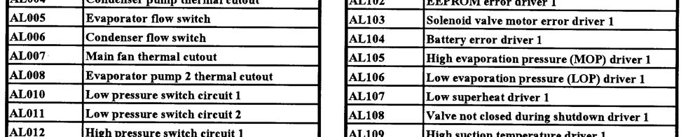


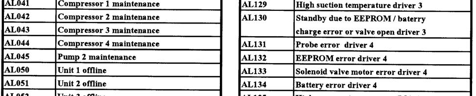

48 47
TECHNICAL GUIDE DESCRIPTION SPLIT-SYSTEM AIR-COOLED CONDENSING UNITS MODELS: HF-07 FEATURES B-0703
 TECHNICAL GUIDE SPLIT-SYSTEM AIR-COOLED CONDENSING UNITS MODELS: HF-07 DESCRIPTION These Sunline 2000 units are completely assembled, piped and wired at the factory to provide one-piece shipment and rigging.
The six in-house brands are Classic, Cooline, CoolCare, Clima Tech, Geoclima and Kessler Clima Tech.
 Company Business Zamil Air Conditioners was founded in 1974, and is the first major business venture in manufacturing sector for the Al Zamil group of Companies. It is also the first manufacturing unit
B. Unit construction shall comply with ASHRAE 15 Safety Code, NEC, and ASME applicable codes (U.S.A. codes).
.") Guide Specifications PART 1 GENERAL 1.01 SYSTEM DESCRIPTION Microprocessor controlled, air-cooled liquid chiller utilizing scroll compressors, low sound fans, hydronic pump system and optional fluid storage
Guide Specifications PART 1 GENERAL 1.01 SYSTEM DESCRIPTION Microprocessor controlled, air-cooled liquid chiller utilizing scroll compressors, low sound fans, hydronic pump system and optional fluid storage
SECTION ROTARY-SCREW WATER CHILLERS
 PART 1 GENERAL 1.01 SECTION INCLUDES A. Factory-assembled packaged chiller. B. Charge of refrigerant and oil. C. Controls and control connections. D. Chilled water connections. E. Electrical power connections.
Installation Instructions
 30GTN015-035 Reciprocating Liquid Chillers with ComfortLink Controls 50/60 Hz Installation Instructions CONTENTS Page SAFETY CONSIDERATIONS...................... 1 INSTALLATION.................................1-11
Call us today! (800)
") 500 TON AIR-COOLED CHILLER PA-ACCTR-500 Call us today! (800)341-4297 The 500-Ton portable chiller package features a Trane RTAC chiller unit. Trane leads the industry in providing some of the most reliable,
500 TON AIR-COOLED CHILLER PA-ACCTR-500 Call us today! (800)341-4297 The 500-Ton portable chiller package features a Trane RTAC chiller unit. Trane leads the industry in providing some of the most reliable,
MACH N-407 Heat Pump Air-Cooled Chiller
 MACH060-01-N-407 Heat Pump Air-Cooled Chiller Heat Pump Air-Cooled Chillers for Global Residential and Light Commercial Microclimates MACH NOMENCLATURE BREAKDOWN MACH-060-01 - N - 407 Refrigerant Type
TECHNICAL GUIDE. Description SPLIT-SYSTEM AIR-COOLED CONDENSING UNITS YD360, 480 & THRU 50 NOMINAL TONS YTG-B-0811
 Description These units are completely assembled, piped and wired at the factory to provide one-piece shipment and rigging. Each unit is pressurized with a holding charge of Refrigerant R-410A for storage
Standard and CELDEK Evaporative Cooler Modules Installation, Operation, and Maintenance Manual
 Standard and CELDEK Evaporative Cooler Modules Installation, Operation, and Maintenance Manual Standard Evaporative Cooler CELDEK Evaporative Cooler RECEIVING AND INSPECTION Upon receiving unit, check
MODELS B1PA024, 030 AND 036
 STELLAR 2000 SINGLE PACKAGE HEAT PUMPS INSTALLATION INSTRUCTION Supersedes: 511.26-N1Y (892) 511.26-N1Y (893) MODELS B1PA024, 030 AND 036 035-11622 GENERAL YORK Model B1PA units are factory assembled heat
MAC N-407 Air-Cooled Chiller
 MAC036-01-N-407 Air-Cooled Chiller Air-Cooled Chillers for Global Residential and Light Commercial MicroClimates MAC036 NOMENCLATURE BREAKDOWN MAC036-01 - N - 407 Refrigerant Type Air-Cooled Chiller 036=
30GH Air-Cooled Liquid Chillers 30GH Nominal cooling capacity kw
 Air-Cooled Liquid Chillers Nominal cooling capacity 21-94 kw Carrier is participating in the Eurovent Certification Programme. Products are as listed in the Eurovent Directory of Certified Products. The
Call us today! (800)
") PA-ACCTR-200 Call us today! (800)341-4297 The 200-Ton portable chiller package features a Trane RTAC chiller unit. Trane leads the industry in providing some of the most reliable, efficient and quiet chiller
PA-ACCTR-200 Call us today! (800)341-4297 The 200-Ton portable chiller package features a Trane RTAC chiller unit. Trane leads the industry in providing some of the most reliable, efficient and quiet chiller
C. ASME Compliance: Fabricate and label water chiller heat exchangers to comply with ASME Boiler and Pressure Vessel Code: Section VIII, Division 1.
 SECTION 236426 - ROTARY-SCREW WATER CHILLERS PART 1 - GENERAL 1.1 SUMMARY A. This Section includes packaged, water cooled or air cooled as scheduled, electric-motor-driven, rotary-screw water chillers
.2 Section Waste Management and Disposal.
 Issued 2005/06/01 Section 15624 Packaged Rotary Screw Water Chillers Page 1 of 5 PART 1 General 1.1 RELATED SECTIONS.1 Section 01330 Submittal Procedures..2 Section 01355 Waste Management and Disposal..3
PACKAGE AIR CONDITIONER
 PACKAGE AIR CONDITIONER FORM NO. ATZ-206 TZAA- HIGH EFFICIENCY SERIES NOMINAL SIZE 10 TON [35.2 kw] 10 TON MODEL [35.2 kw] This product is shipped with a nitrogen holding charge that must be vented prior
Standard and CELDEK Evaporative Cooler Modules Installation, Operation, and Maintenance Manual
 Standard and CELDEK Evaporative Cooler Modules Installation, Operation, and Maintenance Manual Standard Evaporative Cooler CELDEK Evaporative Cooler RECEIVING AND INSPECTION Upon receiving unit, check
100 TON AIR-COOLED SCROLL PACKAGED. Call us today! (800) SPECIFICATIONS GENERAL DIMENSIONS ELECTRICAL DATA ADDITIONAL INFORMATION
 SPECIFICATIONS GENERAL DIMENSIONS ELECTRICAL DATA ADDITIONAL INFORMATION") 100 TON AIR-COOLED SCROLL PACKAGED SPECIFICATIONS Call us today! (800)341-4297 Trane Portable Packaged Air Conditioner units contain the best compressor technology available, in order to achieve the highest
100 TON AIR-COOLED SCROLL PACKAGED SPECIFICATIONS Call us today! (800)341-4297 Trane Portable Packaged Air Conditioner units contain the best compressor technology available, in order to achieve the highest
Call us today! (800)
") 150 TON AIR-COOLED CHILLER PA-ACCTR-150 Call us today! (800)341-4297 The 150-Ton portable chiller package features a Trane RTAC chiller unit. Trane leads the industry in providing some of the most reliable,
150 TON AIR-COOLED CHILLER PA-ACCTR-150 Call us today! (800)341-4297 The 150-Ton portable chiller package features a Trane RTAC chiller unit. Trane leads the industry in providing some of the most reliable,
CELDEK Evaporative Cooler Module Installation, Operation, and Maintenance Manual. CELDEK Evaporative Cooler
 CELDEK Evaporative Cooler Module Installation, Operation, and Maintenance Manual CELDEK Evaporative Cooler RECEIVING AND INSPECTION Upon receiving unit, check for any interior and exterior damage, and
Installation Operation Maintenance
 Installation Operation Maintenance Series R Air-Cooled Helical Rotary Liquid Chiller RTAD 085-180 (50Hz) Standard, Free Cooling and Heat Recovery models RTAD-SVX01F-E4 General information Foreword These
TECHNICAL GUIDE MODELS: H5CE090, H3CE120 & H1CE /2, 10, & 12-1/2 NOMINAL TONS EER DESCRIPTION
 TECHNICAL GUIDE SPLIT-SYSTEM AIR-COOLED CONDENSING UNITS SUNLINE 2000ô MODELS: H5CE090, H3CE120 & H1CE150 7-1/2, 10, & 12-1/2 NOMINAL TONS 9.0-9.5 EER DESCRIPTION These Sunline 2000ô units are completely
Exclusively published and distributed by Architectural Computer Services, Inc. (ARCOM) for the AIA
 for the AIA") Page 236423-1 Copyright 2009 by The American Institute of Architects (AIA) Exclusively published and distributed by Architectural Computer Services, Inc. (ARCOM) for the AIA Modified by MSU Physical Plant
Page 236423-1 Copyright 2009 by The American Institute of Architects (AIA) Exclusively published and distributed by Architectural Computer Services, Inc. (ARCOM) for the AIA Modified by MSU Physical Plant
MODELS LIST. Nominal Capacity RT
 1. MODELS LIST. NOMENCLATURE 3. FEATURES 4. PRODUCT DATA 5. PERFORMANCE CORRECTION 6. ANTIFREEZE 7. INSTALLATION 8. ELECTRICAL DATA 9. SCHEMATIC WIRING DIAGRAM 10.MICROPROCESSOR CONTROLLER 11.APPLICATION
TECHNICAL GUIDE DESCRIPTION SPLIT-SYSTEM AIR-COOLED CONDENSING UNITS. HA300, HB360, HB480 & HB thru 50 NOMINAL TONS (50 Hz)
") DESCRIPTION These units are completely assembled, piped and wired at the factory to provide one-piece shipment and rigging. Each unit is pressurized with a holding charge of refrigerant-22 for storage
DESCRIPTION These units are completely assembled, piped and wired at the factory to provide one-piece shipment and rigging. Each unit is pressurized with a holding charge of refrigerant-22 for storage
PDF Created with deskpdf PDF Writer - Trial ::
 Instruction Manual Index Introduction Uncrating and Checking for Damage Locating Your Unit Installation Fill Tank Process Connections Pre Startup Startup Sequence Trouble Shooting Chart Operating Lights
SECTION PACKAGED COMPRESSOR AND CONDENSER UNITS
 SECTION 236200 - PACKAGED COMPRESSOR AND CONDENSER UNITS PART 1 - GENERAL 1.1 RELATED DOCUMENTS A. Drawings and general provisions of the Contract, including General and Supplementary Conditions apply
DOLPHIN RADIATOR & COOLING SYSTEMS P.O.Box: 1424,Ph#: , Fax#: ,
 DOLPHIN RADIATOR & COOLING SYSTEMS P.O.Box: 1424,Ph#: +971-6-5432526, Fax#: +971-6-5432415, Email: dolcool@emirates.net.ae, web site: www.dolphinheattransfer.com NOMENCLATURE: INTRODUCTION DOLCOOL branded
Water-Cooled Dual Compressor Screw Chiller
 Installation Manual IM 692-1 Group: Chiller Part Number: 629955 Effective: May 1997 Supersedes: IM663-1 IM683 IM692 Water-Cooled Dual Compressor Screw Chiller Installation Manual PFS 155C through PFS 210C,
INSTALLATION, OPERATING & MAINTENANCE INSTRUCTIONS FOR 350 SERIES CIRCULATION HEATERS
 INDEECO Circulation Heaters are designed to provide years of trouble free operation if properly installed and maintained. Please read and follow these instructions for installing and maintaining the heater.
SECTION PACKAGED ROOFTOP AIR CONDITIONING UNITS
 SECTION 15732 - PACKAGED ROOFTOP AIR CONDITIONING UNITS PART 1 - GENERAL 1.1 SECTION INCLUDES A. Package roof top unit. B. Heat exchanger. C. Refrigeration components. D. Unit operating controls. E. Roof
30GT FLOTRONIC AIR-COOLED CHILLERS
 30GT-41SB 30GT040-110 FLOTRONIC AIR-COOLED CHILLERS PERFORMANCE DATA FIELD WIRING DIAGRAM 1998 Carrier Corporation Syracuse, New York 13221 Form 30GT-41SB Supersedes 30GT-21SB, 30GT-22SB, 30GT-23SB, Printed
SECTION AIR COOLED WATER CHILLERS
 PART 1 GENERAL 1.1 SECTION INCLUDES A. Chiller package B. Charge of refrigerant and oil C. Controls and control connections D. Chilled water connections E. Starters F. Electrical power connections 1.2
30GN FLOTRONIC II AIR-COOLED CHILLERS
 30GN-19SB 30GN040-110 FLOTRONIC II AIR-COOLED CHILLERS PERFORMANCE DATA FIELD WIRING DIAGRAM 1998 Carrier Corporation Syracuse, New York 13221 Form 30GN-19SB Supersedes 30GN-6SB, 30GN-7SB, 30GN-8SB, Printed
AIR COOLED SCROLL WATER CHILLERS
 GENERAL ELECTRIC AIR COOLED SCROLL WATER CHILLERS R-22 AALQ Series AALQ010A thru AALQ070A 10 TR thru 70 TR 35 kw thru 246 kw GE_AALQ_Series.indd 1 3/26/12 3:30 PM GE_AALQ_Series.indd 2 CONTENTS Model decoding............................................................................
Commercial High-Efficiency Condensing Units
 FORM NO. A22-194 REV. 2 Supersedes Form No. A22-194 Rev. 1 Commercial High-Efficiency Condensing Units RAWL High Efficiency 6.5 & 7.5 TON MODEL [22.86 & 26.38 kw] TABLE OF CONTENTS Model Number Designation...2
PACKAGED AIR COOLED Product Data Catalog
 PACKAGED AIR COOLED Product Data Catalog MODELS ASP-10A ASP-15A ASP-20A ASP-00P ASP-00F ASP-00G A MEMBER OF MARDUK HOLDING COMPANY, LLC The Leader in Modular Chillers ETL and CSA Approved CHILLER MODULES
Installation Instructions
 40MBFQ Floor Console Ductless System Sizes 09 to 12 Installation Instructions TABLE OF CONTENTS PAGE SAFETY CONSIDERATIONS... 2 PARTS LIST... 3 SYSTEM REQUIREMENTS... 4 DIMENSIONS... 5 CLEARANCES... 5
MODELS W1LC220, 260 AND 320 STYLE B
 LIQUID CHILLER (AIR COOLED) INSTALLATION INSTRUCTION Supersedes: 570.05-NY (494) 570.05-N3Y (495) MODELS WLC0, 60 AND 30 STYLE B 035-3053 Only -5 and -46 voltage codes GENERAL YORK s WLC Packaged Air-Cooled
38ASB/CCARS240~600 (036~060) AIR-COOLED CONDENSING UNIT
 AIR-COOLED CONDENSING UNIT") Concepcion Carrier Air conditioning Company Philippines INSTALLATION, START-UP AND SERVICE INSTRUCTIONS 38ASB/CCARS240~600 (036~060) AIR-COOLED CONDENSING UNIT CONTENTS Safety Considerations 1 Complete
Concepcion Carrier Air conditioning Company Philippines INSTALLATION, START-UP AND SERVICE INSTRUCTIONS 38ASB/CCARS240~600 (036~060) AIR-COOLED CONDENSING UNIT CONTENTS Safety Considerations 1 Complete
Surna 25-Ton Chiller Operating & Maintenance Manual
 www.surna.com 303.993.5271 Surna 25-Ton Chiller Operating & Maintenance Manual Models: 300F3-3. 300F4-3, 300FW-3 Revised: July 2015 Table of Contents Warranty Information 4 Limited Warranty 4 Limitation
SLS 1202 to With or without total heat recovery. u Air Cooled Screw Chillers. 262 to 916 kw. Engineering Data Manual
 u Air Cooled Screw Chillers SLS 1202 to 4004 With or without total heat recovery 262 to 916 kw Engineering Data Manual EDM SLS407-A.4GB Date : December 2008 Supersedes : TM SLS407-A.3GB/11.06 Specifications
ENVIRONMENTAL CONTROL UNIT (ECU) PART NUMBER OPERATIONS AND MAINTENANCE MANUAL
 PART NUMBER OPERATIONS AND MAINTENANCE MANUAL") ENVIRONMENTAL CONTROL UNIT (ECU) PART NUMBER 2001829 OPERATIONS AND MAINTENANCE MANUAL Prepared by: 860 Douglas Way PO Box 530 Natural Bridge Station, VA 24579 1.0 SCOPE: This Operations and Maintenance
ENVIRONMENTAL CONTROL UNIT (ECU) PART NUMBER 2001829 OPERATIONS AND MAINTENANCE MANUAL Prepared by: 860 Douglas Way PO Box 530 Natural Bridge Station, VA 24579 1.0 SCOPE: This Operations and Maintenance
MAC-120HE-03 Air-Cooled Chiller
 MAC-120HE-03 Air-Cooled Chiller 10 Ton / 120,000 BTUH Air-Cooled Chiller 380/415/460-3-50/60 1 HVAC Guide Specifications Air-Cooled Liquid Chiller Nominal Size: 10 Tons Multiaqua Model Number: MAC-120HE-03
MAC-036HE-02-L High Efficiency Air-Cooled Chiller Air-Cooled Chillers for Global Residential and Light Commercial Micro Climates Rev 1.
 MAC-036HE-02-L High Efficiency Air-Cooled Chiller Air-Cooled Chillers for Global Residential and Light Commercial Micro Climates Rev 1.1 HVAC Guide Specifications Air-Cooled Liquid Chiller with Low Ambient
MAC-048HE-01-L High Efficiency Air-Cooled Chiller Air-Cooled Chillers for Global Residential and Light Commercial Micro Climates Rev 1.
 MAC-048HE-01-L High Efficiency Air-Cooled Chiller Air-Cooled Chillers for Global Residential and Light Commercial Micro Climates Rev 1.1 HVAC Guide Specifications Air-Cooled Liquid Chiller with Low Ambient
DENVER PUBLIC SCHOOLS DESIGN AND CONSTRUCTION STANDARDS This Standard is for guidance only. SECTION REFRIGERATION
 PART 0 A/E INSTRUCTIONS 0.01 DESIGN REQUIREMENTS A. General: 1. Design and specify refrigeration systems and equipment in accordance with "Energy Conservation Standards" stipulated in Section 15010, Basic
Installation, Start-Up and Service Instructions
 38AH044-134 Air-Cooled Condensing Units 50/60 Hz Installation, Start-Up and Service Instructions CONTENTS Page SAFETY CONSIDERATIONS...................... 1 INSTALLATION................................
Installation Instructions
 40MAQ High Wall Ductless Split System Sizes 09 to 36 Installation Instructions NOTE: Read the entire instruction manual before starting the installation TABLE OF CONTENTS PAGE SAFETY CONSIDERATIONS 2 PARTS
Catalog Air Cooled Split System Condensing Units for Rooftop Systems and Air Handlers
 Air Cooled Split System Condensing Units for Rooftop Systems and Air Handlers Models RCS 025C through 135C 25 to 135 Tons R-22/R407C Refrigerant Catalog 221-1 Table of Contents Introduction.... 3 The Condensing
Air-Cooled Split System Condensing Unit for Rooftop Systems and Air Handlers
 Catalog 221-1 Air-Cooled Split System Condensing Unit for Rooftop Systems and Air Handlers Model RCS 025C to 135C R-22/R-407C Refrigerant Contents Introduction............................... 3 The Condensing
MAC-060HE-01-L High Efficiency Air-Cooled Chiller Air-Cooled Chillers for Global Residential and Light Commercial Micro Climates Rev 1.
 MAC-060HE-01-L High Efficiency Air-Cooled Chiller Air-Cooled Chillers for Global Residential and Light Commercial Micro Climates Rev 1.2 HVAC Guide Specifications Air-Cooled Liquid Chiller with Low Ambient
Date: August 21, Proposal Number: G Engineer: Payment Terms: Net 30 Days
 Proposal Trane A Division of American Standard Inc. Prepared For: John Weston Desmet Ballestra Job Name: LAUER1 Biodiesel Chiller Pennsylvania Date: August 21, 2006 Proposal Number: G1-95502-1 Engineer:
Direct Drive Fluid Coolers
 H-IM-68 March 2000 Part No. 25001301 Replaces H-IM-44 Direct Drive Fluid Coolers Installation and Maintenance Data Table of Contents Inspection System Warranty Installation...2 Rigging Instructions...3
User s Information and Installation Instructions
 Outdoor Air Conditioner User s Information and Installation Instructions 10 SEER Standard Efficiency Split System These units have been designed and tested for capacity and efficiency in accordance with
DRY CHARGE UNITS. 1.5 to 5 Tons AIR CONDITIONERS LCS13DC PRODUCT SPECIFICATIONS L C S 13 DC MODEL NUMBER IDENTIFICATION
 CONDITIONERS DRY CHARGE UNITS PRODUCT SPECIFICATIONS Bulletin No. 20636 May 204 Supersedes March 202.5 to 5 Tons MODEL NUMBER IDENTIFICATION L C S 3 DC - 036-230 - 2 Lennox Minor Revision Number Air Conditioner
Installation Instructions
 24AHA4 Performance Series Air Conditioner with Puron Refrigerant 1-1/2 to 5 Nominal Tons Installation Instructions Fig. 1-24AHA4 A07532 SAFETY CONSIDERATIONS Improper installation, adjustment, alteration,
Brasch Hazardous Location Unit Heaters
 Brasch Hazardous Location Unit Heaters BHUH Features Designed for rugged industrial applications in hazardous locations where the possibility of explosion or fire exists due to the presence of certain
COLMAC COIL. Installation, Operation, and Maintenance ENG Rev A. Air Cooled Fluid Coolers. Contents. When you want Quality, specify COLMAC!
 COIL Manufacturing Inc. When you want Quality, specify COLMAC! Installation, Operation, and Maintenance ENG00018621 Rev A Air Cooled Fluid Coolers Contents 1. SAFETY INSTRUCTIONS... 1 2. MODEL NOMECLATURE...
CHGV AIR COOLED WATER CHILLER WITH HYDRAULIC EQUIPMENT AIR / WATER 47 to 78 kw
 TECHNICAL INSTRUCTIONS CHGV AIR COOLED WATER CHILLER WITH HYDRAULIC EQUIPMENT AIR / WATER 47 to 78 kw CHGV CHGV 64 CHGV 72 CHGV 80 PHRV heat pump model also available May 2006 10 12 167 - GB - 00 MARKING
Installation Instructions
 40MBFQ Floor Console Ductless System Sizes 09 to 58 Installation Instructions TABLE OF CONTENTS PAGE SAFETY CONSIDERATIONS... 2 PARTS LIST... 3 SYSTEM REQUIREMENTS... 4 WIRING... 4 DIMENSIONS... 5 CLEARANCES...
A. Air-conditioning and Refrigeration Institute (ARI) - Standard 550/590, latest edition, and ARI certification program.
 - Standard 550/590, latest edition, and ARI certification program.") 15684 ROTARY SCREW WATER CHILLERS ************************************************************************************************************* SPECIFIER: CSI MasterFormat 2004 number: 236423 An optional
15684 ROTARY SCREW WATER CHILLERS ************************************************************************************************************* SPECIFIER: CSI MasterFormat 2004 number: 236423 An optional
DLCLRA. INSTALLATION INSTRUCTIONS Outdoor Unit Single Zone Ductless System Sizes 36 to 58 TABLE OF CONTENTS
 DLCLRA INSTALLATION INSTRUCTIONS Outdoor Unit Single Zone Ductless System Sizes 36 to 58 Fig. 1 - Size 36 TABLE OF CONTENTS PAGE SAFETY CONSIDERATIONS... 2 PARTS LIST... 3 SYSTEM REQUIREMENTS... 4 WIRING...
60 TON AIR-COOLED CHILLER. Call us today! (800) PA-ACCTR-60 GENERAL DIMENSIONS ELECTRICAL DATA 60 TON AIR-COOLED CHILLER FEATURES
 PA-ACCTR-60 GENERAL DIMENSIONS ELECTRICAL DATA 60 TON AIR-COOLED CHILLER FEATURES") 60 TON AIR-COOLED CHILLER PA-ACCTR-60 Call us today! (800)341-4297 The 60-Ton portable chiller package features a Trane CGAM chiller unit. Trane leads the industry in providing some of the most reliable,
60 TON AIR-COOLED CHILLER PA-ACCTR-60 Call us today! (800)341-4297 The 60-Ton portable chiller package features a Trane CGAM chiller unit. Trane leads the industry in providing some of the most reliable,
CAS. Product Specifications. COMMERCIAL SPLIT SYSTEMS CONDENSING UNITS R 410A, 6 to 12.5 TONS BUILT TO LAST, EASY TO INSTALL AND SERVICE
 COMMERCIAL SPLIT SYSTEMS CONDENSING UNITS R 410A, 6 to 12.5 TONS BUILT TO LAST, EASY TO INSTALL AND SERVICE CAS Product Specifications Single stage cooling capacity control on all models with Micro channel
OPERATIONS AND MAINTENANCE MANUAL FOR THE 8-TON TURF CART ENVIRONMENTAL CONTROL UNIT (ECU) PART NUMBER
 PART NUMBER") OPERATIONS AND MAINTENANCE MANUAL FOR THE 8-TON TURF CART ENVIRONMENTAL CONTROL UNIT (ECU) PART NUMBER 2001927 Prepared by: 860 Douglas Way PO Box 530 Natural Bridge Station, VA 24579 1 1.0 SCOPE: This
OPERATIONS AND MAINTENANCE MANUAL FOR THE 8-TON TURF CART ENVIRONMENTAL CONTROL UNIT (ECU) PART NUMBER 2001927 Prepared by: 860 Douglas Way PO Box 530 Natural Bridge Station, VA 24579 1 1.0 SCOPE: This
TECHNICAL GUIDE GENERAL SPECIFICATIONS COMMERCIAL SPLIT-SYSTEM COOLING UNITS FOUR PIPE SYSTEM OUTDOOR UNIT: INDOOR UNIT:
 GENERAL SPECIFICATIONS OUTDOOR UNIT: TECHNICAL GUIDE COMMERCIAL SPLIT-SYSTEM COOLING UNITS FOUR PIPE SYSTEM MODELS HB 180 & HB 240 MODELS LB 180 & LB 240 15 & 20 NOMINAL TONS 9.7 EER Two independent refrigerant
Product Data. Features/Benefits. 50TJ S Side Discharge Single-Package Rooftop Units 50/60 Hz 15 to 30 Nominal Tons
 0TJ06-03S Side Discharge Single-Package Rooftop Units 0/ Hz to 30 Nominal Tons Product Data The 0TJ-S series is a special side discharge version packaged unit with capacities of -30 Tons. This unit can
TABLE OF CONTENTS. NOTE: Read the entire instruction manual before starting the installation. TROUBLESHOOTING... 13
 R 410A Duct Free Split System Air Conditioner and Heat Pump Product Family: DFS4(A/H) System, DFC4(A/H)3 Outdoor, DFF4(A/H)H Indoor NOTE: Read the entire instruction manual before starting the installation.
Installation Instructions
 EHNA Electric Heaters 5-20kW For 60 Hz Small Packaged Products MODELS: PAD3, PHD3, PAD4, PHD4, PAD5, PHD5, WPA3, WPH3 Installation Instructions NOTE: Read the entire instruction manual before starting
Installation Instructions
 50ES---A, 50EZ---A, 50VL---A, 50VG---A, 50VR---A, 50VT---A, 604D--- ---A, 607C--- ---A, 607E,--- ---A, 704D--- ---A, 707C--- ---A, 707E--- ---A PA3G --- --- A, PH3G --- --- A SMALL PACKAGED PRODUCTS Electric
DTW Works Master Specification Version 2006 Issued 2006/08/01 Section15621 Packaged Reciprocating Water Chillers Page 1 of 5
 Issued 2006/08/01 Section15621 Packaged Reciprocating Water Chillers Page 1 of 5 PART 1 GENERAL 1.1 RELATED SECTIONS.1 Section 01330 Submittal Procedures..2 Section 01355 Waste Management and Disposal..3
As a standard, heat exchangers are provided with flange water connections (BS Standard Table E). All evaporator are supplied fully insulated.
. All evaporator are supplied fully insulated.") NOMENCLATURE INTRODUCTION The HTT HWDX water-cooled chillers range is the latest addition to HTT s growing family of commercial products, featuring the most current technologies advances. The HWDX main
NOMENCLATURE INTRODUCTION The HTT HWDX water-cooled chillers range is the latest addition to HTT s growing family of commercial products, featuring the most current technologies advances. The HWDX main
30RB/RQ 039S-160S Refrigerant HFC-410A Nominal cooling capacity kw Nominal heating capacity kw
 AIR-COOLED LIQUID CHILLER REVERSIBLE AIR-TO-WATER HEAT PUMP PRO-DIALOG PLUS 30RB/RQ 039S-60S Refrigerant HFC-40A Nominal cooling capacity 40-58 kw Nominal heating capacity 4-59 kw The new generation of
Submittal. Date: September 04, Customer P.O. Number: Customer Project Number:
 Submittal Prepared For: All Bidders Sold To: Date: September 04, 2012 Customer P.O. Number: Customer Project Number: Job Number: Job Name: DCS 12473 80 Ton Chiller Dept of Wildlife 1801 N Lincoln OKLAHOMA
Packaged Air-Cooled Water Chiller
 Installation, Operation and Maintenance Manual IOMM ALR-3 Group: Chiller Part Number: 330145710 Effective: September 2001 Supersedes: IM ALR-2 Packaged Air-Cooled Water Chiller ALR 110F - ALR 150F Refrigerant
Installation, Start-Up and Service Instructions
 Installation, Start-Up and Service Instructions GEMINI 38ARZ007-012, 38ARS008-012 38ARD012-024, 38AKS014-024 Air-Cooled Condensing Units 50/60 Hz CONTENTS Page SAFETY CONSIDERATIONS...1 INSTALLATION...
AIR COOLED PACKAGED CHILLER
 AIR COOLED PACKAGED CHILLER UNIC sal is equipped to produce a wide range of COOLER Air conditioning and Refrigeration units, conforming to the international standards and works continually to improve its
SECTION CENTRIFUGAL WATER CHILLERS Vibration Isolation Pumping Equipment (HVAC) Induced Draft Cooling Tower
 Induced Draft Cooling Tower") SECTION 15682 CENTRIFUGAL WATER CHILLERS PART 1 GENERAL 1.01 SUMMARY A. Related Sections: 1. 15240 - Vibration Isolation. 2. 15540 - Pumping Equipment (HVAC) 3. 15711 - Induced Draft Cooling Tower B. Removal
SECTION 15682 CENTRIFUGAL WATER CHILLERS PART 1 GENERAL 1.01 SUMMARY A. Related Sections: 1. 15240 - Vibration Isolation. 2. 15540 - Pumping Equipment (HVAC) 3. 15711 - Induced Draft Cooling Tower B. Removal
Installation Instructions
 50ES--A, 50EZ--A, 50VG--A, B, 50VL--A, B, 50VR--A, 50VT--A, B 604D-- --A, 607C-- --A, B, 607E-- --A, 704D-- --A, 707C-- --A, B, 707E-- --A PA3G -- -- A, PH3G -- -- A, PA4G, PH4G PAD3, PHD3, PAD4, PHD4,
INSTALLATION INSTRUCTIONS
 INSTALLATION INSTRUCTIONS T CLASS TSA Series 6 to 20 Ton AIR CONDITIONERS 6 20 TONS 506147 01 06/11 Supersedes 3/11 Litho U.S.A. RETAIN THESE INSTRUCTIONS FOR FUTURE REFERENCE IMPORTANT The Clean Air Act
40LM Hz INSTALLATION, START-UP AND SERVICE INSTRUCTIONS CHILLED WATER FAN COIL UNIT
 Carrier International Sdn. Bhd. Malaysia INSTALLATION, START-UP AND SERVICE INSTRUCTIONS CHILLED WATER FAN COIL UNIT 40LM 120-200 50Hz CONTENTS: Physical Data & Dimension 1-3 Safety Considerations 4 Rigging
BESF Box Ventilator. Installation & Operating Manual USA CAN READ AND SAVE THESE INSTRUCTIONS
 Installation & Operating Manual 3001806 03.02 USA CAN BESF Box Ventilator READ AND SAVE THESE INSTRUCTIONS 1200 Northmeadow Parkway, STE 180 Roswell, GA 30076 (770) 587-3238 (800) 255-2923 Fax (770) 587-4731
Commercial High-Efficiency Condensing Units
 FORM NO. A22-193 REV. 3 Supersedes Form No. A22-193 Rev. 2 Commercial High-Efficiency Condensing Units 15 & 20 TON MODEL [52.8 & 70.3 kw] 10 & 12.5 TON MODEL [35.2 & 44.0 kw] 10 THROUGH 20 NOMINAL TON
Installation, Start-Up and Service Instructions
 38AH044-134 Air-Cooled Condensing Units 50/60 Hz Installation, Start-Up and Service Instructions CONTENTS Page SAFETY CONSIDERATIONS...................... 1 INSTALLATION................................
CHS. Product Specifications COMMERCIAL SPLIT SYSTEMS HEAT PUMP UNITS R 410A, 6 10 TONS BUILT TO LAST, EASY TO INSTALL AND SERVICE
 COMMERCIAL SPLIT SYSTEMS HT PUMP UNITS R 410A, 6 10 TONS BUILT TO LAST, SY TO INSTALL AND SERVICE Single stage cooling capacity control on all models All models utilize round copper tube, aluminum plate
APPLICATION MANUAL FOR SCU SERIES COMPRESSOR UNITS AND SWU SERIES WATER COOLED CONDENSING UNITS
 APPLICATION MANUAL FOR SCU SERIES COMPRESSOR UNITS AND SWU SERIES WATER COOLED CONDENSING UNITS SCU-30 SWU-30 Napps Technology Corporation P.O. Box 3066 Longview, TX 75606-3066 Phone: (903) 758-2900 FAX:
Installation Operation Maintenance. Ductable water unit FWD FWD-SVX01D-E4
 Installation Operation Maintenance Ductable water unit FWD 08-12 - 20-30 - 45 General Information Foreword These installation, operation and maintenance instructions are given as a guide to good practice
Brown University Revised August 3, 2012 Facilities Design & Construction Standards SECTION AIR HANDLING UNITS
 SECTION 23 70 00 AIR HANDLING UNITS PART 1. GENERAL 1.1 Section includes air-handling units to 15,000 cfm and accessories. 1.2 Related Sections 1 : A. Division 01 - Brown University Standard for Narragansett
RHGN-H: COMMERCIAL AIR HANDLER WITH VARIABLE FREQUENCY DRIVE (VFD) NOMINAL 10 TONS R-410A REFRIGERANT 2-STAGE AIR-FLOW
 NOMINAL 10 TONS R-410A REFRIGERANT 2-STAGE AIR-FLOW") INSTALLATION INSTRUCTIONS RHGN-H: COMMERCIAL AIR HANDLER WITH VARIABLE FREQUENCY DRIVE (VFD) NOMINAL 10 TONS R-410A REFRIGERANT 2-STAGE AIR-FLOW 92-106595-01-00 TABLE OF CONTENTS Introduction.......................................
INSTALLATION INSTRUCTIONS RHGN-H: COMMERCIAL AIR HANDLER WITH VARIABLE FREQUENCY DRIVE (VFD) NOMINAL 10 TONS R-410A REFRIGERANT 2-STAGE AIR-FLOW 92-106595-01-00 TABLE OF CONTENTS Introduction.......................................
TM Series. Induced Draft, Counter Flow Optional Accessories
 ANTIFREEZE PACKAGE / RESISTANCE HEATING OPTION The antifreeze package is supplied to provide protection against freezing of standing water in the cooling tower sump due to shutdown during winter operation.
SECTION ROTARY SCREW WATER CHILLERS Vibration Isolation Pumping Equipment (HVAC) Induced Draft Cooling Tower
 Induced Draft Cooling Tower") SECTION 15684 ROTARY SCREW WATER CHILLERS PART 1 GENERAL 1.01 SUMMARY A. Related Sections: 1. 15240 - Vibration Isolation. 2. 15540 - Pumping Equipment (HVAC) 3. 15711 - Induced Draft Cooling Tower B.
SECTION 15684 ROTARY SCREW WATER CHILLERS PART 1 GENERAL 1.01 SUMMARY A. Related Sections: 1. 15240 - Vibration Isolation. 2. 15540 - Pumping Equipment (HVAC) 3. 15711 - Induced Draft Cooling Tower B.
SECTION CHILLERS
 SECTION 15650 PART I - GENERAL 1.01 WORK INCLUDED A. Extent of work shall be as indicated on Drawings and provisions of this section, including schedules and equipment lists associated with either Drawings
PROAIR Air Conditioner. CR29 Model INSTRUCTION MANUAL nvent Rev. I P/N
 PROAIR Air Conditioner CR29 Model INSTRUCTION MANUAL Rev. I P/N 89104461 TABLE OF CONTENTS Warranty and Return Policy...2 RECEIVING THE AIR CONDITIONER...3 HANDLING AND TESTING THE AIR CONDITIONER...3
Product Data. 50LJS/TJS Single- Package. Features / Benefits. Rooftop Units - 50 Hz 6 to 12 Nominal Tons
 007-014 Single- Package Rooftop Units - 50 Hz 6 to 12 Nominal Tons Product Data Single package rooftop cooling units with electric heat option. Compact, horizontal discharge units (vertical discharge option),
OWNER S MANUAL. Vintage Classic HEAT COOL models. Proudly Made in the USA
 OWNER S MANUAL Vintage Classic HEAT COOL models Proudly Made in the USA support@aquacomfort.com www.aquacomfort.com/service-and-support 888-475-7443 Manufacturing High Quality, High Efficiency Heat Pump
Installation Instructions
 38MHR Outdoor Unit Single Zone Ductless System Sizes 09 to 24 Installation Instructions NOTE: Read the entire instruction manual before starting the installation. NOTE: Images are for illustration purposes
VariCool VAV Engineering Guide
 Engineering Guide Effective September 2017 Water-Cooled and Chilled Water, Variable Air Volume Contents Product Features... 3 UNIT FEATURES... 3 Product Features... 4 Marvel Plus Microprocessor Control
HTD. High Temperature Non-Cycling Refrigerated Compressed Air Dryers. Operation & Maintenance Manual. MODELS HTD 21 thru HTD 100
 HTD High Temperature Non-Cycling Refrigerated Compressed Air Dryers Operation & Maintenance Manual MODELS HTD 21 thru HTD 100 - TABLE OF CONTENTS - 1.0 GENERAL 2 1.1 How to use this manual 1.2 Symbols
Installation, Start-Up and Service Instructions
 09AZ091-182 Remote Air-Cooled Condensers 90 to 200 Tons Installation, Start-Up and Service Instructions CONTENTS Page SAFETY CONSIDERATIONS.....................1,2 GENERAL........................................