Pulsar System OPERATOR S MANUAL. Model # PS-45
|
|
|
- Chastity Dorsey
- 6 years ago
- Views:
Transcription


1 Pulsar System OPERATOR S MANUAL Model # PS-45
2 Product Stewardship MAKING THE WORLD A BETTER PLACE Lonza is committed to maintaining and improving our leadership in the stewardship of our products. One of our initiatives is to make health, safety, and environmental protection an integral part of a product s life cycle from manufacture, marketing, and distribution to use, recycling, and disposal. Everyone involved with the product has responsibilities to address society s interest in a healthy environment and in products that can be used safely. We are each responsible for providing a safe workplace. All who use and handle products must follow safe and environmentally sound practices. For more information about our Product Stewardship Program, contact your Lonza Representative. For product inquiries, contact PULSAR or pulsar@lonza.com. Dealer Contact:

3 The Major Components - How They Work General Principles of Operation The three main components of the Pulsar 45 Feeder are (from top to bottom) the Briquette Hopper, the manifold spray section and the discharge tank. The water from the pool enters the Pulsar 45 Feeder via the inlet port. The spray manifold then distributes the water onto the briquette grid creating a chlorinated solution. The chlorinated solution falls into the discharge tank and is discharged into the pool recirculation system by the evacuation system. The amount of chlorine discharged from the feeder is determined by the ORP controller or the Timer. When using an ORP controller with this unit, select Yes for the ORP or No to use the internal Timer. Inlet water pressure of 35 to 45 psi [ bar] is required to provide sufficient flow into the Pulsar 45. These pressures will result in an inlet flow of 1.85 gallons/minute [7.00 lpm]. The Pulsar 45 feed rate settings referred to in the Pulsar System Owners manual (right) are calibrated for this flow rate. Flow out of the Pulsar 45 discharge tank requires a vacuum to drain. A minimum outlet flow-rate of 2.5 gal/minute [9.46 lpm] ensures that the flow out of the Pulsar 45 exceeds the flow in. Once the Pulsar 45 is installed, outlet flow can be measured by watching the level in the bottom tank. If the level is rising as the feeder is running, there is insufficient flow out. Figures in Chart below represent Feeder Output in Pounds of Available Chlorine per Day Using the arrows on the touch screen, set the timer to the desired % output rate % output rate lbs [kg] Av. Cl [26.3] [25.0] [23.7] [22.4] [21.0] [19.7] [18.4] [17.1] [15.8] [14.5] [13.2] [11.8] [10.5] [9.2] [7.9] [6.6] [5.3] 15 9 [3.9] 10 6 [2.6] 5 3 [1.3] 0 0 [0.0] rev.4 (3/15/16) Lonza 1200 Bluegrass Lakes Parkway Alpharetta GA, PULSAR 3
![SPECIFICATIONS Model PS-45 Operational Requirements: Inlet pressure (Range)... 35-45 psi [2.41-3.10 bar] Ideal... 37 psi [2.55 bar] Outlet vacuum... 15-29 Hg. [38.1-73.7cm] Operating Temperature.](/docs-images/76/73392950/images/4-0.jpg ".. 40-115ºF [4.4º to 46.1º C] Supply power... 110V, 15A (NEMA 5-15R) Operational Characteristics: Inlet flow (feed & wash)... Outlet flow... 1.85 gpm [7.00 lpm] 2.5 gpm [9.46 lpm] Dimensions: Tubing.")
4 SPECIFICATIONS Model PS-45 Operational Requirements: Inlet pressure (Range) psi [ bar] Ideal psi [2.55 bar] Outlet vacuum Hg. [ cm] Operating Temperature ºF [4.4º to 46.1º C] Supply power V, 15A (NEMA 5-15R) Operational Characteristics: Inlet flow (feed & wash)... Outlet flow gpm [7.00 lpm] 2.5 gpm [9.46 lpm] Dimensions: Tubing... Feeder dimensions... Feeder height... Feeder weight (full)... Feeder weight (empty)... 1/2 [12.7mm] O.D. Polyethylene W: 23 [58.4cm] x D: 24 [61.0cm] 31 [78.7cm] 55 lbs [24.9kg] 30 lbs [13.6kg] Capacity: 25 lbs [11.3kg] Pulsar Plus Briquettes (equivalent to 17 lbs [7.7kg] available chlorine) Feed Rate: Pulsar Plus Briquettes: 3-58 lbs [ kg] of Available Chlorine per day (Pool & Spa) Hopper Fill Increments: Recommended Pool Size 1 : 25 lbs 17 lbs 5, ,000 gallon [18, ,541 liter] unstabilized 1 50, ,000 gallon [189, ,812 liter] stabilized 1 12 lbs 7 lbs 4 lbs Recommended Spa Size 1 : ,000 gallon [1,893-75,708 liter] 1 1 Subject to local health codes 4 Lonza 1200 Bluegrass Lakes Parkway Alpharetta GA, PULSAR rev.4 (3/15/16)


5 General Principles of The Pulsar 45 Components Lid Inlet Manifold and Solenoids Assembly Lid/Hopper Shut-Off Switch/Contact Hopper Wash-down Manifold and Well Agitation Spray Manifold Discharge Valve Outlet and Check Valve Junction Box Safety Overflow Switch Discharge Valve Discharge Valve Float The Pulsar 45 employs an HMI/PLC electronics package for efficient operation and enhanced safety features. The power to the feeder is reduced to 24VDC with the use of a step-down transformer in the control panel. The Pulsar 45 utilizes a PLC Timer with 21 presets for 0-100% control of chlorine output rates. Additionally, Safety Switches are used to interrupt spray to the nozzles when the lid is opened or when the hopper is removed. The Pulsar 45 also incorporates improved maintenance features. Water flow in the unit is designed to remove residue from the feeder base. Listed below is a description of each component of the Electronics Package: Lid Safety Switch: The Pulsar 45 is equipped with a Lid Safety Switch. This switch will interrupt flow to the spray jets when the lid is opened. The design of this feature incorporates a proximity switch so there are no wires connecting the lid to the feeder hopper or the hopper to the base. When the hopper is separated from the feeder base, power to the solenoid is turned off. rev.4 (3/15/16) Lonza 1200 Bluegrass Lakes Parkway Alpharetta GA, PULSAR 5


6 General Principles of The Pulsar 45 Safety Overflow Switch: The Pulsar 45 utilizes a Safety Overflow Switch to prevent the unit from overflowing. Outlet flow can be slowed or stopped by many causes, which can ultimately lead to the unit overflowing. The most common cause would be scale buildup in the venturi, discharge valve and/or outlet tubing. The electronic overflow switch will interrupt power to the solenoid if the level in the discharge tank reaches a set height. When power is interrupted, the solenoid will close and shut off the inlet flow to the spray manifold. The switch, when triggered, also energizes the booster pump. Solenoid/Timer Assembly: The Pulsar 45 relies on a control panel with internal timer and solenoid to control output rate. The Pulsar Control Panel uses a 120V power supply (plug in control panel to dedicated 15A circuit breaker) and the solenoid uses a 24VDC power supply (powered by the control panel). The Pulsar 45 can also be used in conjunction with an ORP controller. The yellow male pigtail from the Pulsar 45 controller should be plugged into the 120V chlorine pigtail of the ORP controller. The signal from the ORP controller will be relayed to the solenoid to feed chlorine. Pulsar Control Panel ORP Controller Chlorine Pigtail 6 Lonza 1200 Bluegrass Lakes Parkway Alpharetta GA, PULSAR rev.4 (3/15/16)

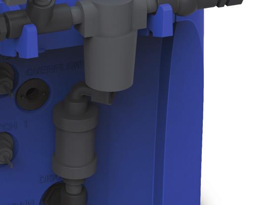
7 General Principles of The Pulsar 45 Test Operation of Electronic Switches: Note: Close inlet and outlet valves. Before start up, lift the briquette screen out of the hopper and set aside on a clean surface. Plug the power cord from the Pulsar 45 controller into a dedicated 15amp GFCI outlet. The touchscreen should be illuminated. Lift the hopper off the base. The lid alarm light will come on. This indicates that the lid switch is working properly. Safety Features Overflow Port: In the event that the solenoids fail to close, an overflow port has been incorporated into the Pulsar 45 design. PVC pipe should be run from this overflow port to a retention area. The solenoid should be checked when an abnormally low or high chlorine reading is indicated in the pool or when water is flowing out of the overflow port through the pipe down to the drain. Next, with the hopper off, remove the valve plate and manifolds and place off to the side. Remove the shield and place to the side. Reach into the base and lift the safety overflow switch. An alarm page for High Level should pop up, indicating that the switch is working properly. Replace the shield, valve plate with manifolds and place the hopper on the base. Next lift the lid. The lid alarm light should come on. This concludes the test procedure. Should the test procedures fail, refer to the Electrical and Control Panel Set-up section (pgs 12-14) for more information or contact your Dealer for additional information. Overflow Port Unplug the controller from the outlet or ORP unit and call the dealer. If water continues to flow into the feeder, the solenoid is stuck open or water is backflowing through outlet piping. If flow stops when the controller is unplugged, the problem is the electronic overflow switch, or outlet piping allowing water to backflow into feeder. In either situation, the inlet/outlet ball valve should be closed and the dealer should be contacted for assistance. rev.4 (3/15/16) Lonza 1200 Bluegrass Lakes Parkway Alpharetta GA, PULSAR 7


![Drain Port: The Drain Port is used to clean excess residue and scale buildup from the feeder discharge tank. Remove the 3/4 [19mm] plug and flush system as needed.](/docs-images/76/73392950/images/8-2.jpg "The shield protects the valve, float and electronic level switch from scale and residue deposits.")
8 General Principles of The Pulsar 45 Maintenance Features Well Agitator: The Well Agitator is designed to keep solids in suspension for removal with the suction created from the venturi. The Well Agitator nozzle can become blocked over time. Remove the well agitator nozzle and clean nozzle orifice if needed. Wash-down & Shield: Below is a picture of the shield and wash-down manifold assembly. This assembly is designed to wash loose solids into the base where they are removed with the chlorine solution. Drain Port: The Drain Port is used to clean excess residue and scale buildup from the feeder discharge tank. Remove the 3/4 [19mm] plug and flush system as needed. The shield protects the valve, float and electronic level switch from scale and residue deposits. Without this shield, scale and residue will increase float weight and decrease buoyancy. In addition, scale buildup can bind pivot points, which could result in valve failure. Drain Port 8 Lonza 1200 Bluegrass Lakes Parkway Alpharetta GA, PULSAR rev.4 (3/15/16)

. Then start Booster pump.")
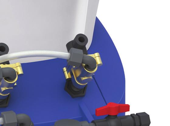
9 Pre-Startup Checklist Following the procedure outlined below will ensure a smooth start-up of the Pulsar 45 Feeder. For seasonal operation, perform this procedure each spring. IMPORTANT!! Do NOT put Pulsar Plus Briquettes in the feeder during the start-up operation. Inlet Water Flow The inlet water flow system is designed to provide a steady side-stream of clean filtered pool water to the feeder. 1. Switch on pool recirculation system, then open valves associated with feeder (suction/ discharge valves). Then start Booster pump. MAKE SURE BOOSTER PUMP VALVES TO SUCTION AND DISCHARGE ARE OPEN TO PREVENT DEAD HEADING. 2. With lid open, place a metal object over the lid switch to see that the four nozzles are spraying water onto the Briquette-Tank grid. 3. Check all lines leading to the feeder for leaks. Hand tighten all fittings if any leaks are found. 4. Check to make sure Safety Overflow Switch is oriented properly with the float below the switch. Chlorine Solenoid Outlet Water Flow As the Discharge Tank fills with water, the float on the Discharge Valve rises with the water level and allows the pump suction to draw the chlorinated water into the pool s recirculation system. When the water level drops, the float falls, shutting off the valve. There is a Check Valve mounted vertically on the Discharge Valve to prevent pool water from backing up into the Discharge Tank. Use the following procedure to ensure that the outlet flow system is operating properly. 1. With the Briquette Hopper of the feeder temporarily off the discharge tank, use a hose or pail to fill the Discharge Tank with sufficient water to open the Discharge Valve. 2. The float should rise, opening the Discharge Valve, allowing water to be drawn out by the Pulsar evacuation system. 3. Check the system for leaks. If small air bubbles are visibly moving, there may be an air leak. Tighten the connectors and make sure that the O-ring is properly installed in the fittings. (NOTE: Air bubbles near the Pulsar 45 Feeder body that do not move are normal and do not indicate leaks.) 4. Tighten connections on check valve true union fittings and Tubing nut on Parker fitting. Tubing nut on Parker Fitting Wash-down/ Well Agitator Solenoid Check Valve union fittings Inlet Ball Valve Inlet Flow to Feeder Line Strainer rev.4 (3/15/16) Lonza 1200 Bluegrass Lakes Parkway Alpharetta GA, PULSAR 9
10 Startup Procedures After completing the PRE-START-UP CHECKLIST, and establishing that all components of the feeder are operating properly, your Pulsar 45 Feeder is ready for start-up. Routine maintenance of the Pulsar 45 Feeder is minimized when proper pool water balance is maintained. Maintain pool water chemistry as follows: Total Alkalinity 60-80ppm Calcium Hardness ppm PH LSI On the ORP screen, there is a button for Chem Balance which will calculate the Langelier Saturation Index given the user input values for TA, ph, Hardness, Temperature and TDS. DANGER: Under no circumstances should you mix calcium hypochlorite with other forms of concentrated chlorine or other chemicals. Fire and/or explosion may result. Caution must be used when refilling dispenser. KEEP OUT OF REACH OF CHILDREN 1. Fill the Briquette Hopper with Pulsar Plus Briquettes. The Briquette Hopper holds 25 pounds [11.3kg] of Pulsar Plus Briquettes. 2. Check the chart on pg 11 to determine an approximate start-up timer setting for your pool. 3. Open all valves to the pool and to the feeder. 4. Monitor the water flow to the feeder daily to ensure that a proper flow is being maintained. Adherence to these recommendations at all times will ensure the most effective and economical performance from the Pulsar 45 Feeder. NOTE: The use of Carbon Dioxide gas (CO2) to lower ph will raise the Total Alkalinity significantly. High total alkalinity (over 80 ppm) will increase scale and solids buildup in feeder. WARNING 5. During the first few days of operation, check chlorine level in the pool frequently to establish the best Timer setting (or ORP Controller setting) for your pool. Adjust the chlorine output either up or down according to the table or, adjust the ORP set-point. WARNING Always monitor the free chlorine residual in the pool water per the health code requirements. If the FAC level exceeds acceptable levels, do not enter the pool until the residual in the acceptable range. The Pulsar 45 Feeder can only be installed with the Booster Pump, Venturi and Flow switch provided with the unit. These components, combined with the Booster pump interlock with the main pool pump, will prevent high levels of chlorine in the pool after Pool pump shut-down. 10 Lonza 1200 Bluegrass Lakes Parkway Alpharetta GA, PULSAR rev.4 (3/15/16)
11 Startup Procedures RECOMMENDED START-UP SETTINGS *Do not exceed 25-ppm stabilizer Control Panel Feed Rate Pool Volume ( Gallons [Liters] ) % Output Stabilized Pool Un-Stabilized Pool 100 N/A N/A 95 N/A N/A 90 N/A N/A 85 N/A N/A 80 N/A N/A 75 N/A N/A 70 N/A 105,000 [397,425] 65 N/A 97,500 [369,038] 60 N/A 90,000 [340,650] 55 N/A 82,500 [312,263] 50 N/A 75,000 [283,875] 45 N/A 67,500 [255,488] 40 N/A 60,000 [227,100] ,500 [596,138] 52,500 [198,713] ,000 [510,975] 45,000 [170,325] ,500 [425,813] 37,500 [141,938] 20 90,000 [340,650] 30,000 [113,550] 15 67,500 [255,488] 22,500 [85,163] 10 45,000 [170,325] 15,000 [56,775] 5 22,500 [85,163] 7,500 [28,388] 0 0 [0] 0 [0] rev.4 (3/15/16) Lonza 1200 Bluegrass Lakes Parkway Alpharetta GA, PULSAR 11
12 Pulsar 45 Startup Procedure: Control Panel Electrical and Control Panel Set-up Starting Up The System For The First Time When you first power on the control panel, you should see this screen. Tap once on the screen to go to the main control page. 5. ALARM SCREEN This is a signal light as well as a button. When pressed, the Alarm page is brought up. This will show you your active alarms, and allow you to troubleshoot directly from that page. Instructions are included for troubleshooting on the screen. 6. E-STOP OK This is a button which will turn off all outputs when pressed. (The PUMP will turn OFF, the FEED and WASH valves will CLOSE). The control screen is the main screen for the system, and the one that you will see when running normally. 7. FEED START This button toggles the feed process, ON or OFF. 8. WASH TIMER This button goes to the WASH TIMER page where you can set up the afterfeed wash time. Default is 5 minutes. 9. SET UP This page goes to the system set up pages. All settings on following pages should be set up initially, then verified after any power outage. 1. NO FLOW This is your flow indication. When RED, no flow is being detected by the flow switch. When GREEN, flow is good and the system will be allowed to run. 2. PUMP OFF This indicates the state of the booster pump start signal. 3. FEED OFF This indicates the state of the FEED valve. 4. WASH OFF This indicates the state of the WASH valve. 12 Lonza 1200 Bluegrass Lakes Parkway Alpharetta GA, PULSAR rev.4 (3/15/16)
13 Pulsar 45 Startup Procedure: Control Panel Electrical and Control Panel Set-up INITIAL PROGRAMMING SETUP Press SET UP button from Main control screen. The following ORP/FEED Screen will appear. The box in the top center of the screen will show the feeder size that the control panel is set up for. If it reads P000, then the feeder size needs to be set up on the subsequent page. See SETTING FEEDER SIZE section below. The DILUTION Button allows the WASH valve to activate simultaneously with the FEED valve. This is a permanent ON setting with the PS-45, but can be toggled ON/OFF with the PS-140 and PS-500 feeders. The GREEN color means that it is set to run both valves. RED means that only FEED will run when FEED is requested. SETTING FEEDER SIZE Push right arrow button on ORP/Feed screen to get to the Feeder Size screen shown in figure below. You must login as Tech to change the feeder model size. This should be set by the installer. See installation manual. Use the dark blue buttons to toggle the switch to select Pulsar Model Size based on the unit installed. SETTING UP BOOSTER PUMP Use the dark blue buttons to select the Booster Pump Mode. NOTE: Switch must be toggled from ECONO to ON then back to ECONO to set mode on initial installation. Select whether you would like to feed chlorine based on an ORP input or based on a given feed rate (+/- 10%). When ORP is selected YES, then the FEED RATE Button is disabled. Only one method of chlorine feeding can be selected at any given time. When ORP is selected NO, then the FEED RATE Button is enabled. See SETTING FEED RATE section below. ON INITIAL INSTALLATION: The ORP Selection must be toggled from YES to NO then back to YES if YES is the desired selection. FEED cycle will not start unless ORP is toggled first. ECONO MODE (Default) Runs the Booster Pump for 20 seconds after the last valve activation (whether FEED or WASH), then shuts off the Booster Pump to conserve energy. The minimum runtime is 5 minutes. ALWAYS ON Push the pump start button to toggle the booster pump ON/OFF. This runs the Booster Pump continuously while the Flow Switch is ON and when the alarm state is OK. If pump has not run for minimum time of 5 minutes, pump will not turn off when button is pressed. *Remember that the E-STOP and FLOW SWITCH preempt any activation of the pump. If the E-STOP is activated (manually pressed), or the FLOW SWITCH (doesn t sense flow), then the pump will not turn ON. rev.4 (3/15/16) Lonza 1200 Bluegrass Lakes Parkway Alpharetta GA, PULSAR 13

14 Pulsar 45 Startup Procedure: Control Panel Electrical and Control Panel Set-up SETTING FEED RATE ALARM button will highlight the most recent alarm. Pressing ALARM HELP will open a popup window with a troubleshooting guide for that particular alarm. For example: By pressing the FEED or FEED + buttons, the feed rate for chlorine can be adjusted from 0 100% in 5% increments (DEFAULT is 0%). The FEED TABLE button will open a pop-up window (shown below) which will correlate percent to pounds chlorine per day. The pop-up can be closed by pressing the X in the top right of the screen. Pressing the ALARM RESET button resets the alarm momentarily. This will allow you to see if the alarm is persistent, or already cleared, and in a non-alarm state. ALARMS 1. LID HOPPER OPEN Press the X in the top right of the screen to close the window and return to the FEED RATE meter. ALARM PAGE 2. LID OPEN TOO LONG greater than 1 hour 3. PUMP STARTER SWITCHED OFF 4. PUMP STARTER TRIPPED greater than 15 seconds 5. EXTERNAL SHUT DOWN EVENT 6. LEVEL SWITCH HIGH 7. LEVEL SWITCH HIGH TOO LONG greater than 10 minutes The ALARM PAGE can be accessed by pressing the ALARM Lamp on the MAIN CONTROL screen. The last active alarm will be shown. Each alarm can be highlighted by pressing the SCROLL UP and SCROLL DOWN buttons. Pressing the LAST 14 Lonza 1200 Bluegrass Lakes Parkway Alpharetta GA, PULSAR rev.4 (3/15/16)
15 Pulsar 45 Preventative Maintenance Calcium Hypochlorite by the nature of its manufacture contains a small amount of calcium carbonate. Proper water balance will minimize the buildup of calcium carbonate solids in the Pulsar 45 Feeder; however, periodic cleaning of feeder components is normal and recommended. The following is a list of the parts to be cleaned and the proper procedures to do so. A. Recommended Maintenance Frequency Based on Alkalinity Parts to be Inspected and Cleaned Alkalinity (ppm) Frequency Estimated Time 1. Hopper, Grid, and sensors 2. Spray Nozzle and Wash/Agitator Nozzle 3. Venturi 4. Manifold Assemblies 80 max Quarterly (90 days) 2 hours 5. Supply and Discharge Lines 6. Booster Pump 7. Solenoid Valves rev.4 (3/15/16) Lonza 1200 Bluegrass Lakes Parkway Alpharetta GA, PULSAR 15
 Lid Sensor Shut-off (Part 3, pg 29): Inspect lid sensor operation by removing the lid and making")


16 Pulsar 45 Preventative Maintenance B. Preventative Maintenance Schedule Description / Maintenance Preventative Maintenance: Daily (24 HRS) Lid Sensor Shut-off (Part 3, pg 29): Inspect lid sensor operation by removing the lid and making sure the alarm light on the control panel screen is activated deactivate by re-installing lid. If the alarm does not come on when the lid is removed, visually inspect the lid sensor making sure that no foreign material is on it. If the alarm does not reset when the lid is replaced, adjust the switch closer to the lid contactor by sliding up bracket. If no debris is on the sensor and adjustments don t appear to be working, notify maintenance to inspect/repair the lid sensor. Note: The light on the lid switch will illuminate when connection is made with lid contactor. Check Duration: About 1 minute MON TUES WED THUR FRI SAT SUN Item Hopper Basket/Grid (Parts 2 & 4, pg 29): Visually inspect hopper briquette level. Verify there is sufficient amount of briquettes to be fed until next scheduled visit. Make sure the grid of the hopper is completely covered with a depth of at least 3 to 4 of briquettes. If briquettes are moist around the outer circumference of the hopper, move the briquettes to the center of the hopper and add new briquettes around them. Check Duration: Less than 2 minutes MON TUES WED THUR FRI SAT SUN Inlet Manifold Assembly (pg 30 & 32): Verify that there are no leaks at any of the fittings. Check Duration: About 1 minute MON TUES WED THUR FRI SAT SUN continued 16 Lonza 1200 Bluegrass Lakes Parkway Alpharetta GA, PULSAR rev.4 (3/15/16)
 Inlet Supply Solenoid Valves (Part 20, pg 32): Ensure that the solenoid valve coils are not hot to")

17 Pulsar 45 Preventative Maintenance B. Preventative Maintenance Schedule Description / Maintenance Preventative Maintenance: Daily (24 HRS) Inlet Supply Solenoid Valves (Part 20, pg 32): Ensure that the solenoid valve coils are not hot to the touch. If coil is hot to the touch, make sure inlet ball valve (part 24, pg 32) is open during fill cycle allowing water to pass though the solenoid valves for water cooling. If ball valve is open then either replace or rebuild solenoid valve. The solenoid valve could buzz very slightly under normal conditions. If the solenoid starts making a rattling noise when energized, consider replacing or rebuilding the valve. Check Duration: About 1 minute Item MON TUES WED THUR FRI SAT SUN Booster Pump: Visually check for leaks on and around the pump, including the suction and discharge piping and fittings. Check Duration: About 1 minute MON TUES WED THUR FRI SAT SUN Preventative Maintenance: Weekly (7 DAYS) Description / Maintenance Item Inlet Manifold Line Strainer Assembly (Part 21, pg 32): Close the water supply valve (Part 24, pg 32) and remove strainer bowl from the inlet manifold and inspect for debris. Remove strainer screen and wash it out prior to replacing it back into the strainer bowl. If the screen appears damaged or has a hole in it, replace with a new screen. Visually inspect for cracks on the strainer and make sure there is no leak anywhere on the strainer s body. Re-install the strainer bowl back into the strainer body. Check Duration: Around minutes WEEK 1 WEEK 2 WEEK 3 WEEK 4 WEEK 5 WEEK 6 WEEK 7 WEEK 8 continued rev.4 (3/15/16) Lonza 1200 Bluegrass Lakes Parkway Alpharetta GA, PULSAR 17
 Manifold Assemblies (Spray Manifold, Wash Manifold, pg 30): Verify that there are no leaks at")
: Visually inspect the hopper grid for any plugging.")
18 Pulsar 45 Preventative Maintenance B. Preventative Maintenance Schedule Description / Maintenance Preventative Maintenance: Monthly (30 DAYS) Manifold Assemblies (Spray Manifold, Wash Manifold, pg 30): Verify that there are no leaks at any of the fittings. Make sure the inlet ball valve (part 24, pg 32) is open during operation. Check Duration: Around 5 minutes Item First Week of: Jan Feb Mar Apr May Jun Jul Aug Sep Oct Nov Dec Hopper Basket / Grid (Parts 2 & 4, pg 29): Visually inspect the hopper grid for any plugging. If plugging or build up is observed at 50% or greater on the grid, then clean existing hopper/grid or replace with a previously cleaned hopper/grid. While inspecting the basket also look for any visible cracks. If any cracks are found, replace the grid as soon as possible before starting the feeder back up. Please follow Cleaning Procedure (pgs 22-26) to clean the hopper and grid if required. Note: To increase the period between Grid cleanings, allow Briquette Hopper to completely empty once a week. Check Duration: About 5 minutes First Week of: Jan Feb Mar Apr May Jun Jul Aug Sep Oct Nov Dec continued 18 Lonza 1200 Bluegrass Lakes Parkway Alpharetta GA, PULSAR rev.4 (3/15/16)
 Venturi (Part 33, pg 33): Inspect venturi and verify that it is not clogged with scale build up.")

 float, DV arm, and DV body (parts 8, 9, and 10, pg 31).")
19 Pulsar 45 Preventative Maintenance B. Preventative Maintenance Schedule Description / Maintenance Preventative Maintenance: Monthly (30 DAYS) Venturi (Part 33, pg 33): Inspect venturi and verify that it is not clogged with scale build up. This will require that the tubing and tubing fittings be removed from the suction side of the venturi. If there is any scale build-up, perform cleaning procedure on pg 25. Visually look at lines and fittings on the inlet, outlet, and suction sides of the venturi for leaks. If needed, re-tighten the fittings or replace them. Item Check Duration: 10 minutes First Week of: Jan Feb Mar Apr May Jun Jul Aug Sep Oct Nov Dec Feeder Discharge Tank / Molded Base with Inserts (Part 1, pg 29): Visually inspect the solution reservoir and ensure that there is no calcium buildup on the discharge valve (DV) float, DV arm, and DV body (parts 8, 9, and 10, pg 31). Calcium buildup on the DV can dramatically interfere with feeder discharge operation that can lead engaging the overflow switch or possible overflowing of the feeder. If any build up is found please follow Cleaning Procedure (pgs 22-26) Check Duration: 5 minutes First Week of: Jan Feb Mar Apr May Jun Jul Aug Sep Oct Nov Dec continued rev.4 (3/15/16) Lonza 1200 Bluegrass Lakes Parkway Alpharetta GA, PULSAR 19
 Safety Overflow Switch (Part 37, pg 29): Visually inspect the Safety Overflow Switch when the")

20 Pulsar 45 Preventative Maintenance B. Preventative Maintenance Schedule Description / Maintenance Preventative Maintenance: Monthly (30 DAYS) Safety Overflow Switch (Part 37, pg 29): Visually inspect the Safety Overflow Switch when the solution tank is empty to ensure no calcium deposits are forming around the sensor and that the sensor is not corroding. If degradation is observed, replace switch. Make sure switch is positioned as shown in the figure at right. Check Duration: 2 minutes Item First Week of: Jan Feb Mar Apr May Jun Jul Aug Sep Oct Nov Dec Preventative Maintenance: Quarterly (90 DAYS) Description / Maintenance Item Spray Nozzles (Part 28, pg 30): Remove hopper basket and visually inspect spray nozzles for fouling. Remove spray tree and ensure no foreign material is stuck inside the spray nozzles. If foreign material is found, clean the spray tree by soaking in Pulsar Plus Acid Cleaner 50 and follow the Chemical Hopper cleaning procedure (pgs 22-23). Do not mechanically clean nozzles. This could lead to damaging the nozzles. Replace any spray nozzle that is physically damaged, or not spraying in a uniform full-cone pattern. After installing the spray tree, make sure that the spray tree and nozzles are level this is achieved by applying a level to the spray tree and nozzles. Check Duration: Less than 10 minutes First Week of: Jan (once during Jan-Mar) Apr (once during Apr-Jun) Jul (once during Jul-Sep) Oct (once during Oct-Dec) continued 20 Lonza 1200 Bluegrass Lakes Parkway Alpharetta GA, PULSAR rev.4 (3/15/16)
 Washdown and Well Agitator Nozzles (Parts 30 and 31, pg 30): Remove hopper basket and")

21 Pulsar 45 Preventative Maintenance B. Preventative Maintenance Schedule Description / Maintenance Preventative Maintenance: Quarterly (90 DAYS) Washdown and Well Agitator Nozzles (Parts 30 and 31, pg 30): Remove hopper basket and visually inspect wash down nozzles for fouling. The well agitator nozzle can become blocked over time. Remove the washdown and well agitator nozzles and clean nozzle orifice if needed by soaking in a Pulsar Plus Acid Cleaner 50 solution. Check Duration: Around 10 minutes Item First Week of: Jan (once during Jan-Mar) Apr (once during Apr-Jun) Jul (once during Jul-Sep) Oct (once during Oct-Dec) Preventative Maintenance: Biennial (2 YEARS) Description / Maintenance Item Inlet Supply Solenoid Valves (Part 20, pg 32): Replace solenoid valve every two years to ensure proper system operation. Check Duration: No more than 30 minutes First Week of: Jan (once every 2 years) Jan (once every 2 years) rev.4 (3/15/16) Lonza 1200 Bluegrass Lakes Parkway Alpharetta GA, PULSAR 21
 Caution: Don PPE prior to performing any work on the Pulsar System and handling the Pulsar Plus Acid Cleaner 50 Cleaning Solution Tool Step Instruction")
22 Pulsar 45 Cleaning Procedure Personal Protective Equipment and Parts Needed for Cleaning Safety Tools Rubber Gloves Safety Glasses Apron Putty Knife Clean 5 gallon plastic bucket Hose Supplies Drain line from base of feeder (routed to the drain) Caution: Don PPE prior to performing any work on the Pulsar System and handling the Pulsar Plus Acid Cleaner 50 Cleaning Solution Tool Step Instruction Use Pulsar Plus Acid Cleaner 50 Warning: DO NOT use Muriatic Acid to perform the following procedures. Chlorine gas may evolve causing serious injury or possible death. Chemical Hopper Cleaning Tool Step Instruction 1.1 To the maximum extent practicable, allow feeder to use up the briquettes in the hopper prior to cleaning. 1.2 Shut the venturi isolation ball valve (Part 24, pg 33) on the Discharge Assembly from the feeder to the venturi. 1.3 Shut the inlet isolation ball valve (Part 24, pg 32) on the Inlet Manifold Assembly from the outlet of the booster pump to the feeder. 1.4 Remove the Briquette hopper lid (Part 3, pg 29) and then remove the Briquette hopper (Part 2, pg 29) off of the Base Assembly (Part 1, pg 29) and place on a clean surface. continued 22 Lonza 1200 Bluegrass Lakes Parkway Alpharetta GA, PULSAR rev.4 (3/15/16)
23 Pulsar 45 Cleaning Procedure Chemical Hopper Cleaning Tool Step Instruction 1.5 Remove any remaining unused Pulsar Plus Briquettes and place into a clean dry bucket, and then remove the Briquette Grid (Part 4, pg 29). Unused Briquettes, including wetted briquettes may be reused once cleaning is complete. Dispose of used mushy Briquettes properly. Dissolve mushy Briquettes in clean 5 gallon pail of water to make chlorine solution. Add chlorine solution to skimmer or gutter. 1.6 Clean off as much solid material from the grid and hopper as possible. 1.7 Place the briquette grid and hopper in a shallow tub. Fill with 2 gallons [7.57 liters] of water. Slowly pour 1 quart [.95 liters] Pulsar Plus Acid Cleaner 50 into the tub. 1.8 Frequent agitation may be required to dissolve residue and scale. Allow acid to dissolve residue and scale, evident by the foaming action. 1.9 After 1 hour, check for the presence of scale on the grid. If necessary, add additional Pulsar Plus Acid Cleaner 50 to dissolve any remaining scale or scrape with putty knife. Rinse the Briquette grid thoroughly with fresh water Repeat steps 1.8 through 1.10 to clean the spray tree, and wash manifold assembly Visually verify the spray nozzles are clean prior to reassembling Once clean, replace Valve Plate Assembly and Briquette Hopper back on top of the Base Assembly then place the Briquette grid back into the bottom of the hopper Open the venturi isolation ball valve (Part 24, pg 33) on the Discharge Assembly from the feeder to the venturi Open the inlet isolation ball valve (Part 24, pg 32) on the Inlet Manifold Assembly from the outlet of the booster pump to the feeder. rev.4 (3/15/16) Lonza 1200 Bluegrass Lakes Parkway Alpharetta GA, PULSAR 23

 on the Discharge Assembly from the feeder to the venturi. 2.")
 above if hopper requires cleaning. 2.")
 (Part 10, pg 31), DV arm (Part 9, pg 31), and DV float (Part 8, pg 31) can be cleaned in place with acid. 2.")
24 Pulsar 45 Cleaning Procedure Tank Cleaning Tool Step Instruction 2.1 To the maximum extent practicable, allow feeder to use up the briquettes in the hopper prior to cleaning. 2.2 Shut the venturi isolation ball valve (Part 24, pg 33) on the Discharge Assembly from the feeder to the venturi. 2.3 Shut the inlet isolation ball valve (Part 24, pg 32) on the Inlet Manifold Assembly from the outlet of the booster pump to the feeder. 2.4 Remove the hopper and lid from the Base Assembly and place on a clean surface. Follow Chemical Hopper Cleaning instructions (steps ) above if hopper requires cleaning. 2.5 Remove the entire Valve Plate including the spray manifolds and solenoids and place in bucket or tray. 2.6 The discharge valve (DV) (Part 10, pg 31), DV arm (Part 9, pg 31), and DV float (Part 8, pg 31) can be cleaned in place with acid. 2.7 Rinse the DV parts with fresh water and examine them carefully to remove any excess scaling formed on the parts. 2.8 Remove the 3/4 [19 mm] plug from the drain port (pg 8) and route it to a drain. Caution: Place a pan below the drain during removal of the drain plug. Some chlorine solution may be released. Flush out the Base Assembly through the drain port. Allow the feeder to completely drain then close the drain port. continued 24 Lonza 1200 Bluegrass Lakes Parkway Alpharetta GA, PULSAR rev.4 (3/15/16)
25 Pulsar 45 Cleaning Procedure Tank Cleaning Tool Step Instruction 2.9 Fill the Base Assembly 1 [2.54mm] below the overflow port (pg 7) and add 1 quart [0.95 liters] Pulsar Plus Acid Cleaner Frequent agitation may be required to dissolve residue and scale. Allow acid to dissolve residue and scale, evident by the foaming action After 1 hour, check for the presence of scale in the tank and on the DV parts. If necessary, add additional Pulsar Plus Acid Cleaner 50 to dissolve any remaining scale or scrape with putty knife Open the venturi isolation ball valve (Part 24, pg 33) on the Discharge Assembly from the feeder to the venturi. Allow the venturi to suck the remaining solution from the Base. The solution from the Base Assembly will clean the discharge valve, outlet tubing and venturi Replace hopper and lid back onto the Base Assembly. Replace the Valve Plate Assembly along with the connected Spray Manifold Assembly (pg 30) to the Base Assembly Open the inlet isolation ball valve (Part 24, pg 32) on the Inlet Manifold Assembly from the outlet of the booster pump to the feeder. Venturi Cleaning Tool Step Instruction 3.1 Shut the inlet valve (part 24, pg 32) to the feeder. 3.2 Get a gallon jug and fill half of it with water 3.3 Add 1/2 quart of Pulsar Plus Acid Cleaner 50 to the water in the jug. 3.4 Shut the outlet valve (part 24, pg 33) to the Venturi. 3.5 Disconnect the tubing from the check valve. 3.6 Place end of tubing in the jug with the water/acid cleaning solution. 3.7 Open outlet valve and suck out 1/2 of the contents then shut the valve. 3.8 Let the solution sit for 15 minutes. 3.9 Open the outlet valve and draw out remainder of the solution from the jug Shut the outlet valve and reconnect tubing to the check valve outlet Open the outlet valve to the venturi Open the inlet valve to the feeder. rev.4 (3/15/16) Lonza 1200 Bluegrass Lakes Parkway Alpharetta GA, PULSAR 25
 to the feeder. 4.")


26 Pulsar 45 Cleaning Procedure Check Valve Cleaning Tool Step Instruction 4.1 Shut the inlet valve to the feeder and outlet valve to the venturi (parts 24, pg 32 & 33) to the feeder. 4.2 Get a gallon jug and fill half of it with water 4.3 Add 1/2 quart of Pulsar Plus Acid Cleaner 50 to the water in the jug. 4.4 Disconnect the check valve (part 6, pg 31) from the tubing. 4.5 Disassemble the check valve in accordance with the picture making sure not to lose any of the components. 4.6 Place check valve parts in the Pulsar Plus Acid Cleaner 50 for 15 minutes to remove scale build up. 4.7 Reassemble check valve verifying proper placement of components back into the assembly. 4.8 Reconnect check valve into tubing and open inlet and outlet valves. check valve scale buildup examples 26 Lonza 1200 Bluegrass Lakes Parkway Alpharetta GA, PULSAR rev.4 (3/15/16)
27 Pulsar 45 Troubleshooter s Guide Problem Cause Solution Insufficient water flow to feeder Check water flow through spray nozzles Safety Overflow Switch in closed position Inlet Valved closed Inlet Filter plugged Solenoid Valve not operating properly Feed rate/output too low Feeder empty No/low inlet water flow Clean spray nozzles with compressed air If SO Switch is stuck, lower gently to reset switch Open Inlet Valve Clean Inlet Filter Check with Dealer Increase feed rate/output on timer or ORP unit Refill Briquette Tank with Pulsar Plus Briquettes See insufficient water flow section Insufficient chlorine in pool Excess chlorine in pool Air Leaks Feeder overflow Outlet Shutoff Valve closed Clogged Discharge Tubing Clogged Briquette Tank Grid Clogged Venturi System Automatic Controller problem Feed rate/output to high Discharge Tubing not properly installed in fittings Discharge Valve seat failure Scale prevents Discharge Valve from properly seating Pinched O-rings in Tubing Connectors Discharge Tubing clogged Insufficient outlet suction Emergency overflow switch failure Open Outlet Shutoff Valve Replace discharge tubing Refer to Section A Remove and soak in dilute Pulsar Plus Acid Clear 50 or E-Stop engaged on Control Panel Refer to Automatic Controller manual Decrease feed rate/output on timer Reinstall Discharge Tubing Replace Discharge Valve Arm Remove Discharge Valve Assembly and soak in dilute Pulsar Plus Acid Cleaner 50 to remove scale Inspect O-rings on discharge side of feeder Refer to Section A or Replace Discharge Tubing Check with Dealer Check with Dealer rev.4 (3/15/16) Lonza 1200 Bluegrass Lakes Parkway Alpharetta GA, PULSAR 27
28 Pulsar 45 Feeder: Detailed View See pgs for Diagram Descriptions 28 Lonza 1200 Bluegrass Lakes Parkway Alpharetta GA, PULSAR rev.4 (3/15/16)
29 Pulsar 45 Feeder: Detailed View See pgs for Diagram Descriptions See Wash Manifold Assembly (pg 30) See Spray Manifold Assembly (pg 30) See Valve Plate Assembly (pg 32) See Inlet Manifold Assembly (pg 32) See Discharge Assembly Kit (pg 31) rev.4 (3/15/16) Lonza 1200 Bluegrass Lakes Parkway Alpharetta GA, PULSAR 29
30 Pulsar 45 Feeder: Assembly Views See pgs for Diagram Descriptions Spray Manifold Assembly Wash Manifold Assembly 30 Lonza 1200 Bluegrass Lakes Parkway Alpharetta GA, PULSAR rev.4 (3/15/16)
31 Pulsar 45 Feeder: Assembly Views See pgs for Diagram Descriptions Discharge Assembly Kit rev.4 (3/15/16) Lonza 1200 Bluegrass Lakes Parkway Alpharetta GA, PULSAR 31
32 Pulsar 45 Feeder: Assembly Views See pgs for Diagram Descriptions Inlet Manifold Assembly Valve Plate Assembly 32 Lonza 1200 Bluegrass Lakes Parkway Alpharetta GA, PULSAR rev.4 (3/15/16)
33 Pulsar 45 Feeder: Assembly Views See pgs for Diagram Descriptions Pulsar Installation Kit flow to pool /2 Slip PVC Ball Valve (installer provides) cut 1-1/2 PVC pipe (installer provides) 24 flow from feeder /2 thread x slip PVC union 1-1/2 slip x 1/2 FNPT TEE (installer provides) flow to feeder 22 cut 1-1/2 PVC pipe (installer provides) 35 flow from pool /2 Slip PVC Ball Valve (installer provides) rev.4 (3/15/16) Lonza 1200 Bluegrass Lakes Parkway Alpharetta GA, PULSAR 33
34 Pulsar 45 Feeder: Diagram Descriptions Diagram Number Location Part Number Qty/ Unit Description 1 MOLDED BASE ASSEMBLY MOLDED BASE WITH INSERTS 2 HOPPER ASSEMBLY HOPPER 3 LID ASSEMBLY LID 4 HOPPER ASSEMBLY GRID 5 DISCHARGE ASSEMBLY KIT /2 X 1-1/2 NIPPLE 6 DISCHARGE ASSEMBLY KIT CHECK VALVE 7 DISCHARGE ASSEMBLY KIT /2 INCH PVC ELBOW 8 DISCHARGE ASSEMBLY KIT DV Float 9 DISCHARGE ASSEMBLY KIT DV Arm 10 DISCHARGE ASSEMBLY KIT DV BODY 11 DISCHARGE ASSEMBLY KIT DV NUT 11 VALVE PLATE ASSEMBLY DV NUT 12 DISCHARGE ASSEMBLY KIT DV GASKET 13 DISCHARGE ASSEMBLY KIT W8ME8 14 BASE ADD ON'S (Features) BRACKET LID SWITCH 15 BASE ADD ON'S (Features) ISOPLAST BOLT 1/4-20 X 3/4 16 BASE ADD ON'S (Features) BASE ADD ON'S (Features) J-BOX GASKET 18 VALVE PLATE ASSEMBLY VALVE PLATE 19 VALVE PLATE ASSEMBLY W8ME8 19 INLET MANIFOLD ASSEMBLY W8ME8 20 VALVE PLATE ASSEMBLY J-BOX ASSEMBLY WITH TURCK CABLE SOLENOID (ASCO 8212A519S0100F1) 21 INLET MANIFOLD ASSEMBLY LINE STRAINER ASSEMBLY 22 INLET MANIFOLD ASSEMBLY W8MC8 22 INSTALLATION KIT W8MC8 23 INLET MANIFOLD ASSEMBLY PVC THREADED NIPPLE - 1/2 NPT X 2 24 INLET MANIFOLD ASSEMBLY MF BALL VALVE 24 INSTALLATION KIT MF BALL VALVE 25 INSTALLATION KIT INLET MANIFOLD ASSEMBLY /2 NPT TEE 1-1/2" x 12" PVC THREADED NIPPLE 27 SPRAY MANIFOLD ASSEMBLY SPRAY MANIFOLD 28 SPRAY MANIFOLD ASSEMBLY E.BC NOZZLE 34 Lonza 1200 Bluegrass Lakes Parkway Alpharetta GA, PULSAR rev.4 (3/15/16)
35 Pulsar 45 Feeder: Diagram Descriptions Diagram Number Location Part Number Qty/ Unit Description 29 WASH MANIFOLD ASSEMBLY WASH MANIFOLD 30 WASH MANIFOLD ASSEMBLY AGITATION NOZZLE 31 WASH MANIFOLD ASSEMBLY WASH-DOWN NOZZLE ( ) 32 CONTROL PANEL CONTROL PANEL WITH IDEC FT1A TOUCH 33 INSTALLATION KIT VENTURI (MAZZEI 1585X) 34 INSTALLATION KIT P8FC8 35 INSTALLATION KIT BOOSTER PUMP 36 MOLDED BASE ASSEMBLY SHIELD BASE ADD ON'S (Features) BASE ADD ON'S (Features) INSTALLATION KIT SAFETY OVERFLOW SWITCH (INCLUDED WITH 79616) LID SAFETY SWITCH (INCLUDED WITH 79616) 1-1/2 SLIP x 1-1/2 FNPT PVC UNION NOT SHOWN IN DIAGRAMS N/A CONTROL PANEL FLOW SWITCH N/A INSTALLATION KIT ' 1/2"OD LDPE TUBING N/A MOLDED BASE ASSEMBLY HD/Local 6 OLN MOUNT CABLE TIE N/A MOLDED BASE ASSEMBLY HD/Local 6 OLN CABLE TIE N/A BASE DRAIN ASSEMBLY HD/Local 1 3/4" PVC HEX PLUG N/A BASE DRAIN ASSEMBLY HD/Local 1 INLET DRAIN SIPHON ASSEM N/A VALVE PLATE ASSEMBLY HD/Local 1 1/2" OD LDPE TUBING 24" LONG N/A VALVE PLATE ASSEMBLY HD/Local 1 1/2" OD LDPE TUBING 18" LONG N/A MISCELLANEOUS 1 MANUALS N/A MISCELLANEOUS 1 WARRANTY CARD rev.4 (3/15/16) Lonza 1200 Bluegrass Lakes Parkway Alpharetta GA, PULSAR 35


36 PLC Menu Map Main Control Page 36 Lonza 1200 Bluegrass Lakes Parkway Alpharetta GA, PULSAR rev.4 (3/15/16)
37 Warranty Policy Pulsar 45 Feeder Lonza warrants equipment (excluding electrical components) of its manufacture and bearing its identification to be free of defects in workmanship and material. Lonza s liability under this warranty extends for a period of two (2) years from the date of installation as performed by an Authorized Commercial Dealer Representative and registered with Lonza Water Chemicals via the Lonza Commercial Chlorinator Warranty Registration Card. Systems for which there is no Warranty Registration Card on file carry no warranty of any kind, expressed or implied. In addition, each system is covered by a sixty (60) -day, 100% buy-back guarantee. If the original purchaser ( owner ) is dissatisfied with the Pulsar 45 Feeder performance for any reason, they can return it to the Authorized Commercial Pool Dealer for a full refund. The equipment must have received normal use and care, and Lonza must be notified in writing before the sixty (60) days have expired. There is no reimbursement for chemicals used during the sixty (60) -days. Lonza disclaims all liability for damage during transportation, for consequential damage of whatever nature, for damage due to handling, installation or improper operation, and for determined suitability for the use intended by purchaser ( owner ). Lonza make no warranties, either expressed or implied, other than those stated above. No Lonza Representative or Authorized Commercial Dealer Representative has authority to change or modify this warranty in any respect. Pulsar 45 Parts Lonza warrants equipment parts of its manufacture and bearing its identification to be free of defects in workmanship and material. Lonza s liability under this warranty extends for a period of ninety (90) days from the date of installation as performed by an Authorized Commercial Dealer Representative. This warranty is restricted to Pulsar 45 Feeder parts purchased on a replacement basis Bluegrass Lakes Parkway Alpharetta GA, PULSAR
38 NOTES 38 Lonza 1200 Bluegrass Lakes Parkway Alpharetta GA, PULSAR rev.4 (3/15/16)
39 NOTES rev.4 (3/15/16) Lonza 1200 Bluegrass Lakes Parkway Alpharetta GA, PULSAR 39
40 Lonza Emergency Action Network (LEAN) The Lonza Emergency Action Network ( LEAN ) is Lonza s emergency action system. Call the LEAN system at ) in North America, and at (Country Code for the United States) elsewhere in the world. The LEAN system is available 24 hours a day, 7 days a week for assistance with spills, injuries and emergencies of any kind. It uses computers and other systems to make Lonza s environmental, technical transportation, toxicological and other expertise about its products readily available to anyone needing assistance. The LEAN system also includes emergency response teams capable of providing on-site support throughout North America. (800) (From outside North America, call after the country code for the US, ) Additionally, in the event of an emergency, CHEMTREC (Chemical Transportation Emergency Center) should be contacted. CHEMTREC is a national center established by the Chemical Manufacturers Association (CMA) in Washington, DC, to relay pertinent emergency information concerning specific chemicals on request. CHEMTREC has a 24-hour toll-free telephone number (800) , intended primarily for use by those who respond to chemical transportation emergencies. CHEMTREC may also be accessed through the CMA website at Material Safety Data Sheets (MSDS) can be obtained by contacting (800)-511-MSDS. SKU No.: Revision 4 (03/15/16) All trademarks belong to Lonza or its affiliates Bluegrass Lakes Parkway Alpharetta GA, PULSAR
Operator s Manual. rev.1 (8/13/13) 1200 Lower River Road, P.O. Box 800 Charleston, TN PULSAR
 1200 Lower River Road, P.O. Box 800 Charleston, TN PULSAR") Operator s Manual 45 Dealer Contact Model # PS 45 1200 Lower River Road, P.O. Box 800 Charleston, TN 37310-0800 1-800-4-PULSAR is now a part of www.lonza.com Product Stewardship MAKING THE WORLD A BETTER
Operator s Manual 45 Dealer Contact Model # PS 45 1200 Lower River Road, P.O. Box 800 Charleston, TN 37310-0800 1-800-4-PULSAR is now a part of www.lonza.com Product Stewardship MAKING THE WORLD A BETTER
Operator s Manual. Model # PS Arch Chemicals, Inc Lower River Road P.O. Box Box 800 Charleston, TN PULSAR
 Operator s Manual Model # PS 8000 Arch Chemicals, Inc. 1200 Lower River Road P.O. Box Box 800 Charleston, TN 37310-0800 1-800-4-PULSAR 1/10/03 REV 6 Dealer Contact: Product Stewardship MAKING THE WORLD
Operator's Manual. Model #PS Arch Chemicals, Inc Lake Park Drive Smyrna, GA PULSAR
 Operator's Manual Model #PS 8000 06.26.06 Arch Chemicals, Inc. 1955 Lake Park Drive Smyrna, GA 30080 1-800-4-PULSAR Product Stewardship Making the World a Better Place" Arch is committed to maintaining
Arch Feeder: Installation Manual
 Arch Feeder: Installation Manual Model #A300N Arch Chemicals, Inc. 1200 Lower River Road, P.O. Box 800 Charleston, TN 37310-0800 Product Stewardship MAKING THE WORLD A BETTER PLACE Arch is committed to
Installation and Operation Manual. ACF-18 Automatic Chlorinating Feeder
 Installation and Operation Manual ACF-18 Automatic Chlorinating Feeder Operating Specifications Inlet Flow: 1.0-1.5 gpm Outlet Flow: = Inlet Flow Inlet Pressure: 10-45 psi Maximum Output: 26 lbs. of Available
chlorination evolved FEEDERS New Design HIgh Efficiency Made in the U.S.A.
 chlorination evolved 45 140 500 FEEDERS New Design HIgh Efficiency Made in the U.S.A. chlorination evolved New design! Highly efficient! 4 Based on feedback from customers 4 PLC driven control box with
Pulsar System INSTALLATION MANUAL. Model # PS-45 Model # PS-500 Model # PS-140
 Pulsar System INSTALLATION MANUAL Model # PS-45 Model # PS-500 Model # PS-140 Product Stewardship MAKING THE WORLD A BETTER PLACE Lonza is committed to maintaining and improving our leadership in the stewardship
Owner s Manual RD432-0 Chemical Controller
 Owner s Manual RD432-0 Chemical Controller Table of Contents I. Introduction page 2 A. Water Chemistry page 2 B. Safety page 3 C. System Components page 4 D. Specifications page 7 E. Controller Panel Descriptions
Professional Series. Chemical Feed System Model # US Patent No. 6,752,930 B2
 Professional Series Chemical Feed System Model # 22152-02 US Patent No. 6,752,930 B2 Product Manual SureWater Technologies, Inc. The Solution X-2 Model # 22152-02 Table of Contents 1. Installation Instruction
M770 ph Controller Owner s Manual
 M770 ph Controller Owner s Manual Table of Contents I. Introduction page 2 A. Water Chemistry page 2 B. Safety page 3 C. System Components page 4 D. Specifications page 7 E. Controller Panel Descriptions
M790 ph/orp Controller. Owner s Manual
 M790 ph/orp Controller Owner s Manual Table of Contents I. Introduction page 2 A. Water Chemistry page 2 B. Safety page 3 C. System Components page 4 D. Specifications page 7 E. Controller Panel Descriptions
OPERATION AND MAINTENANCE MANUAL ELC-810 AUTOMATIC WATER LEVEL CONTROLLER. AquatiControl Technology
 OPERATION AND MAINTENANCE MANUAL ELC-810 AUTOMATIC WATER LEVEL CONTROLLER AquatiControl Technology 3820 South Federal Blvd Sheridan, Colorado 80110 Toll Free: 877.755.8817 Fax: 303.761.1499 www.aquaticontrol.com
IMPORTANT SAFETY INSTRUCTIONS EC-AG1-25 EC-AG1, EC-AG2 SAVE THESE INSTRUCTIONS.
 IMPORTANT SAFETY INSTRUCTIONS 2 1. Read and Follow All Instructions 2. Read this manual completely before attempting installation. 3. All permanent electrical connections should be made by a qualified
Next Generation Corona Discharge Installation & Operation Manual
 Next Generation Corona Discharge Installation & Operation Manual 4-2319-01 Rev.A IMPORTANT SAFETY INSTRUCTIONS READ & FOLLOW ALL INSTRUCTIONS Read this manual completely before attempting installation.
Rules for Safe Operation
 Rules for Safe Operation Important: Do not attempt to operate the CleanStation until you have read thoroughly and understand all instructions and safety rules contained in this manual. Failure to comply
Safety. Rinse Kit for Multi-Pro 1200 and 1250 Turf Sprayers Model No Safety and Instructional Decals. Installation Instructions
 Rinse Kit for Multi-Pro 1200 and 1250 Turf Sprayers Model No. 106-4842 Form No. 3353-529 Rev B Installation Instructions Note: Determine the left and right sides of the machine from the normal operating
Xaact Spot. Xaact Hot Spot
 Xaact Spot & Xaact Hot Spot INFORMATION & OPERATING INSTRUCTIONS READ AND UNDERSTAND THESE INSTRUCTIONS BEFORE OPERATING THE MACHINE 78-00012 Rev. 101211 1 CONTENTS: Machine Specifications............
Ozone Generator Systems
 PZ2-1 & PZ2-2 - Commercial and Residential Pools & Spas Ozone Generator Systems INSTALLATION GUIDE and OPERATION MANUAL T. O3 NATURAL TECHNOLOGY Reduces Chemical Usage, Improves Sanitation Produces Crystal
Upholstery and Drapery Cleaner. Operator and Parts Manual. Model No.: gal Extractor. MNL32506 Rev. 00 (08-98)
") 32506 Upholstery and Drapery Cleaner Model No.: 32506 3 gal Extractor Operator and Parts Manual KLEENRITE 1122 MAPLE STREET MADERA CA 93637 U.S.A. FAX: 1-559-673-5725 CUSTOMER SERVICE: 1-800-241-4865 MNL32506
32506 Upholstery and Drapery Cleaner Model No.: 32506 3 gal Extractor Operator and Parts Manual KLEENRITE 1122 MAPLE STREET MADERA CA 93637 U.S.A. FAX: 1-559-673-5725 CUSTOMER SERVICE: 1-800-241-4865 MNL32506
Manual update 2016 MC37/MFC3600
 Manual update 2016 MC37/MFC3600 SETUP INSTRUCTIONS Evaporative cooling works on the principle of heat absorption by moisture evaporation. Simply put, heat is removed from the air as water evaporates. You
Model 8780 INSTALLATION, OPERATION & MAINTENANCE INSTRUCTIONS. Tempering Skid General Area Classification & Class I Division 2. No.
 INSTALLATION, OPERATION & MAINTENANCE INSTRUCTIONS 1455 Kleppe Lane Sparks, NV 89431-6467 (775) 359-4712 Fax (775) 359-7424 E-mail: haws@hawsco.com Website: www.hawsco.com Model 8780 Tempering Skid General
HARMSCO INSTALLATION AND OPERATION MANUAL UPFLOW SWIMMING POOL CARTRIDGE FILTER CARTRIDGE CLEANING INSTRUCTIONS HARMSCO CARTRIDGES
 HARMSCO INSTALLATION AND OPERATION MANUAL UPFLOW SWIMMING POOL CARTRIDGE FILTER CARTRIDGE CLEANING INSTRUCTIONS HARMSCO CARTRIDGES May be cleaned and reused before replacement is necessary. Cartridge cleaning
READ AND UNDERSTAND THESE INSTRUCTIONS BEFORE OPERATING THE MACHINE
 XAACT Xtract 200 INFORMATION & OPERATING INSTRUCTIONS READ AND UNDERSTAND THESE INSTRUCTIONS BEFORE OPERATING THE MACHINE 78-00018 Rev B 032912 1 CONTENTS: Machine Specifications............ 2 Record Important
model NO. LSS GALLON SKID MOUNTED HIGH PRESSURE SPRAYER ASSEMBLY / OPERATION INSTRUCTIONS / PARTS
 000 model NO. LSS- 00 GALLON SKID MOUNTED HIGH PRESSURE SPRAYER ASSEMBLY / OPERATION INSTRUCTIONS / PARTS Part number and descriptions can be obtained from the illustrated parts list section of this manual.
Water Technologies. Strantrol System 3i. Technical Guide
 Water Technologies Strantrol System 3i Technical Guide Table of Contents Warning Notifications...i Mounting Chapter 1...1 1.1 Environmental Conditions...1 Plumbing Chapter 2...3 2.1 Sample Stream General
C-Box 100, H-Box 200 & H-Box 500
 C-Box 100, H-Box 200 & H-Box 500 Table of Contents Technical specifications... 3 Safety precautions... 4 Grounding instructions... 4 Machine components... 5-6 lectrical requirements... 6 Machine set-up...
OPERATOR'S MANUAL. IMPORTANT: READ OPERATOR'S MANUAL CAREFULLY Please fill out & return your warranty card! DP80405
 CARBON SPOT 30 EXTRACTOR OPERATOR'S MANUAL IMPORTANT: READ OPERATOR'S MANUAL CAREFULLY Please fill out & return your warranty card! DP80405 Diamond Products www.diamondproductsus.com Printed in the U.S.A.
Manual for MC37/MFC3600
 Manual for MC37/MFC3600 SETUP INSTRUCTIONS Evaporative cooling works on the principle of heat absorption by moisture evaporation. Simply put, heat is removed from the air as water evaporates. You feel
J120 STEAM BOOSTER INSTALLATION, OPERATION, AND SERVICE MANUAL J120 STEAM BOOSTER. J120 Steam Booster Manual D
 INSTALLATION, OPERATION, AND SERVICE MANUAL J120 STEAM BOOSTER J120 STEAM BOOSTER J120 Steam Booster Manual REVISION HISTORY Revision Letter Revision Date Made by Applicable ECNs Details A 10-27-04 CBW
CBT LW MAINTENANCE GUIDE
 CBT LW MAINTENANCE GUIDE PICTOGRAMS Each Signifier displayed here is specific to this User Manual. Menu Previous Advance Note Tip Example Powder Feeder Mixing Bowl Weigh Scale CBP Tanks Control Panel PSD
Control Panel For Water Wash Hoods AM2
 Control Panel For Water Wash Hoods AM2 For further information Call: (919) 554-1025 Or Fax: (919)554-1525 Aqua-Matic 117 Franklin Park Ave. Youngsville, NC 27506 TABLE OF CONTENTS AQUA-MATIC LIMITED WARRANTY
Sloan AQUS Installation Instruction, Operation, and Maintenance Guide
 Code No: 0816444 Rev. 3 (09/10) Models HMA-7000 HMA-7000-EU (Euro) Sloan AQUS Installation Instruction, Operation, and Maintenance Guide The Sloan AQUS is designed to reuse sink water as an alternative
MODEL ORP/pH Digital Controller
 MODEL 554000 ORP/pH Digital Controller Operating Manual Rola-Chem Digital Controller PN 554102 6/01/2012 Page: 1 of 20 QUICK START REFERENCE Use this section for reference - please read all safety instructions
Manual for MC91 SETUP INSTRUCTIONS
 Manual for MC91 SETUP INSTRUCTIONS Evaporative cooling works on the principle of heat absorption by moisture evaporation. Simply put, heat is removed from the air as water evaporates. You feel this principle
Patriot. Automatic Pool Vacuum Cleaner. Patent No. 5,794,293. Owner's Guide. Model *Recommended for 3/4 HP and above
 Patriot Model 5-2046-000 Automatic Pool Vacuum Cleaner Patent No. 5,794,293 Owner's Guide *Recommended for 3/4 HP and above 365-1926-1 CAUTIONS 1. Remove the vacuum from the pool prior to super chlorinating
MP-MBA-45T-1/60T-1 / 75T-1
 MASTER Water Conditioning Corp. www.masterwater.com Installation and Operation Manual MP-MBA-45T-1/60T-1 / 75T-1 with the 268/762 Logix Control Valve July 2006 Table of Contents Page No. Topic Description
EcoMaster - Residential Pools up to 40,000 Gallons
 - Residential Pools up to 40,000 Gallons INSTALLATION/ OPERATION GUIDE Reduces Chemical Usage, Improves Sanitation Produces Crystal Clear Water Copyright 2013 Prozone Water Products: 3004 11 th Ave. -
Instruction Manual - Anti-Siphon Ejector Chlorine & Sulfur Dioxide 500 PPD (10 kg/h) Maximum Capacity
 Maximum Capacity") - Anti-Siphon Ejector Chlorine & Sulfur Dioxide 500 PPD (10 kg/h) Maximum Capacity 100 PPD (2 kg/h) Chlorine or Sulfur Dioxide 250 & 500 PPD (5 & 10 kg/h) Chlorine or Sulfur Dioxide Anti-Siphon Ejector
- Anti-Siphon Ejector Chlorine & Sulfur Dioxide 500 PPD (10 kg/h) Maximum Capacity 100 PPD (2 kg/h) Chlorine or Sulfur Dioxide 250 & 500 PPD (5 & 10 kg/h) Chlorine or Sulfur Dioxide Anti-Siphon Ejector
OWNER S MANUAL. Vintage Classic HEAT COOL models. Proudly Made in the USA
 OWNER S MANUAL Vintage Classic HEAT COOL models Proudly Made in the USA support@aquacomfort.com www.aquacomfort.com/service-and-support 888-475-7443 Manufacturing High Quality, High Efficiency Heat Pump
WL380 QUICK START GUIDE
 WL380 QUICK START GUIDE WARNING! Only trained and qualified technicians should attempt to install, maintain, or service Waterlogic equipment. Failure to follow all instructions in this manual could result
TFC 400. OPERATOR MANUAL Clarke MODEL /09 Rev C Document Number
 TFC 400 OPERATOR MANUAL Clarke MODEL 56380773 1 11/09 Rev C Document Number 56380889 IMPORTANT SAFETY INSTRUCTIONS This machine is only suitable for commercial use, for example, in hotels, schools, hospitals,
INSTALLATION. and INSTRUCTION MANUAL. for QUALITY AIR BREATHING SYSTEMS. Model ABM - 715
 INSTALLATION and INSTRUCTION MANUAL for QUALITY AIR BREATHING SYSTEMS Model ABM - 715 M A R T E C H S E R V I C E S C O M P A N Y P.O. Box 7079 OFFICE: 800-831-1525 Mazeppa, MN 55956 Fax : (507)843-4953
Installation and Maintenance Guide
 Installation and Maintenance Guide Inline Chlorinator TM Vitasalus is a trademark owned by Vitasalus, Inc. Vitasalus, Inc. 248-585-8815 1409-H Allen Drive. Troy, Michigan 48083 USA www.vitasalus.com Table
FOR THE RECORD. You should record the model and serial numbers, which can be found on the back of the unit, for future reference.
 FOR THE RECORD You should record the model and serial numbers, which can be found on the back of the unit, for future reference. Warranty: 18 mo. on unit and 1 year on check valve assembly Model: The Ozone
BACK WASH INSIDE THE SPA
 BACK WASH INSIDE THE SPA Lower the temperature to 90 degrees and let the unit run approximately 10-15 minutes. This gives the heating element the chance to cool down. Now unplug the power pack Using a
INSTALLATION. and INSTRUCTION MANUAL. for QUALITY AIR BREATHING SYSTEMS. Model ABM - 700
 INSTALLATION and INSTRUCTION MANUAL for QUALITY AIR BREATHING SYSTEMS Model ABM - 700 M A R T E C H S E R V I C E S C O M P A N Y P.O. Box 7079 OFFICE: 800-831-1525 Mazeppa, MN 55956 Fax : (507)843-4953
READ AND UNDERSTAND THESE INSTRUCTIONS BEFORE OPERATING THE MACHINE
 XAACT Xtract 500 INFORMATION & OPERATING INSTRUCTIONS READ AND UNDERSTAND THESE INSTRUCTIONS BEFORE OPERATING THE MACHINE 78-00015 Rev B 032912 1 CONTENTS: Machine Specifications............ 2 Record Important
English. Your Model Number is: HD1500 IMPORTANT
 Your Model Number is: HD1500 IMPORTANT Attention Valued Customer: The serial number of your machine and date of purchase is necessary information to facilitate warranty claims and the ordering of replacement
WM-450-PT WM-900-PT Commercial Wall Mounted Reverse Osmosis
 WM-450-PT WM-900-PT Commercial Wall Mounted Reverse Osmosis Installation And Service Manual Watts Pure Water 1725 W. Williams Dr. C-20., Phoenix, Arizona 85027 Phone: 888-774-7405 Fax: 602-588-0356 www.wattspurewater.com
Vacuum-ultraviolet Ozone Systems. Installation & Operation Manual. Model OZ-SPA
 OzoneAX 3 T Vacuum-ultraviolet Ozone Systems Installation & Operation anual odel OZ-SPA A. Important Safety Instructions IPORTANT SAFETY INSTRUCTIONS When using this electrical equipment, basic safety
SYSTEMS for CATALYTIC FILTERS
 OP40U5F, OP40B5F, OP80U10F, OP80B10F, OP120U15F & OP120B15F INSTALLATION, OPERATION & SERVICE INSTRUCTIONS Hydrogen Sulfide Removal SYSTEMS for CATALYTIC FILTERS NO DIAPHRAGMS OR AIR CELLS COMPLETELY CORROSION
GLC/GW-100 MANUAL INSTALLATION SERVICE PARTS REV.1.01
 Owner s Manual Keep with machine for reference GLC/GW-100 MANUAL INSTALLATION SERVICE PARTS REV.1.01 CMA DISHMACHINES 12700 KNOTT STREET GARDEN GROVE, CALIFORNIA 92841 800-854- 6417 FAX 714-895- 2141 www.cmadishmachines.com
Installation and Operation Manual MG-304. Please read this manual carefully before use.
 Installation and Operation Manual MG-304 Please read this manual carefully before use. 1 P a g e Important Safety Instructions: Warning! Use this unit only for its intended purposes or as described in
EXTRACTOR Operation & Maintenance Manual
 EXTRACTOR Operation & Maintenance Manual 12 Gallon Carpet Extractor Models 2-100 2-100-H 3-100 3-100-H 2-200 2-200-H 3-200 3-200-H 2-500 2-500-H 3-500 3-500-H US & Foreign Patents Pending The design features
IMPORTANT SAFETY INSTRUCTIONS READ AND FOLLOW ALL INSTRUCTIONS SAVE THESE INSTRUCTIONS
 Operating Manual MODEL RC554P AND 554200 ph Digital Controller FEED ph FLOW ALERT AUTO MODE SET LEVEL FEED TIME ph CALIB FLOW SWITCH ph ph OUTPUT POWER IMPORTANT SAFETY INSTRUCTIONS READ AND FOLLOW ALL
OWNER S MANUAL. Models: Herkules Equipment Corporation 2760 Ridgeway Court Walled Lake, MI USA Fax
 Part# 1000692 7/12/99 tn INSTRUCTIONS This manual contains important information concerning the installation and operation of the gun washers listed at the right. Read manual thoroughly and keep for future
Ultraviolet Systems UV-C 50 INSTALLATION INSTRUCTIONS & PRODUCT MANUAL
 Ultraviolet Systems Inc. UV-C 50 INSTALLATION INSTRUCTIONS & PRODUCT MANUAL TABLE OF CONTENTS SECTION 1 General Information 1A. Description...1 1B. Specifications...1 SECTION 2 Installation 2A. Pool Preparation...
Getz Equipment Innovators 450 lb Dual Portable Dry Chemical Fill System
 Getz Equipment Innovators 450 lb Dual Portable Dry Chemical Fill System 1 Revised 11/18/10 2320 Lakecrest Drive, Pekin IL 61554 PH. (888) 747-4389 Fax (309) 495-0625 Website: www.getzequipment.com LIMITED
MODEL L-1X & L-1X16 Installation & Operations
 Owner s Manual Keep with machine for reference MODEL L-1X & L-1X16 Installation & Operations Rev 1.16A CMA DISHMACHINES 12700 KNOTT AVENUE GARDEN GROVE, CALIFORNIA 92841 800-854-6417 FAX 714-8 95-2 141
INSTALLATION and OPERATION BALL WASHER MODEL NO: BW-022
 Easy Picker Golf Products, Inc. 415 Leonard Blvd. N., Lehigh Acres, FL 33971 PH: 239-368-6600 FAX: 239-369-1579 Service: 800-982-4653 SALES: 800-641-4653 www.easypicker.com salesdept@easypicker.com INSTALLATION
Owner's Manual. (200 Gallon Lawn Service Skid Sprayer) Technical Specifications. Operation. General Information. Warranty/Parts/Service
 Technical Specifications. Operation. General Information. Warranty/Parts/Service") Owner's Manual (00 Gallon Lawn Service Skid Sprayer) Technical Specifications. Horsepower Recoil Start Engine Roller Cast Iron Pump 0 Gallons Per Minute at 0 PSI Pressure Gauge-Adjustable Pressure Range
Owner's Manual (00 Gallon Lawn Service Skid Sprayer) Technical Specifications. Horsepower Recoil Start Engine Roller Cast Iron Pump 0 Gallons Per Minute at 0 PSI Pressure Gauge-Adjustable Pressure Range
READ AND FOLLOW ALL INSTRUCTIONS SAVE THESE INSTRUCTIONS
 READ AND FOLLOW ALL INSTRUCTIONS SAVE THESE INSTRUCTIONS 1 IMPORTANT SAFETY INSTRUCTIONS Read the instructions The appliance is not to be used by persons (including children) with reduced physical, sensory
MODEL L-1X & L-1X16 Installation & Operations
 Owner s Manual Keep with machine for reference MODEL L-1X & L-1X16 Installation & Operations Rev 1.15 CMA DISHMACHINES 12700 KNOTT AVENUE GARDEN GROVE, CALIFORNIA 92841 800-854-6417 FAX 714-8 95-2 141
TECHNICAL INSTRUCTIONS
 TECHNICAL INSTRUCTIONS 24-Month Maintenance Kit P/N 58015-02 For BMK2.0 (Nozzle Mix) Description of Document: This TID provides the procedures to perform recommended 24-Month maintenance on the following
M820 ph/dual ORP Controller. Owner s Manual
 M820 ph/dual ORP Controller Owner s Manual Table of Contents I. Introduction page 2 A. Water Chemistry page 2 B. Safety page 3 C. System Components page 4 D. Specifications page 7 E. Controller Panel Descriptions
TECHNICAL MANUAL TM... Fryer, Deep-Fat, Electric w/solid State Controls 440 Volt, 60 HZ, 3 Phase NSN:
 TM... TECHNICAL MANUAL MODEL USN-50 DESCRIPTION Fryer, Deep-Fat, Electric w/solid State Controls 440 Volt, 60 HZ, 3 Phase NSN: Commercial & Marine Cooking Equipment Gas & Electric Last Updated September
Installation, Operation, and Maintenance Manual
 Installation, Operation, and Maintenance Manual Product Preservers Anti-Scale System Chemical-Free, Salt-Free Scale Prevention Introduction The Product Preservers Anti-Scale System will condition the tap
CAUTION UM120W (RIGHT TANK) FOR WATER BORNE PAINTS ONLY UM120W (RIGHT TANK) SECTION IS NOT DESIGNED FOR USE WITH SOLVENT BASED PAINT
 FOR WATER BORNE PAINTS ONLY UM120W (RIGHT TANK) SECTION IS NOT DESIGNED FOR USE WITH SOLVENT BASED PAINT") OPERATING MANUAL SOLVENT AND WATER BASE SPRAY GUN CLEANER UG5000W and UG5500W CAUTION UM120W (RIGHT TANK) FOR WATER BORNE PAINTS ONLY UM120W (RIGHT TANK) SECTION IS NOT DESIGNED FOR USE WITH SOLVENT BASED
OPERATING MANUAL SOLVENT AND WATER BASE SPRAY GUN CLEANER UG5000W and UG5500W CAUTION UM120W (RIGHT TANK) FOR WATER BORNE PAINTS ONLY UM120W (RIGHT TANK) SECTION IS NOT DESIGNED FOR USE WITH SOLVENT BASED
SAFETY PRECAUTIONS. 2) Before operating machine: - Make sure all safety devices are in place and operate properly.
 Before operating machine: - Make sure all safety devices are in place and operate properly.") TABLE OF CONTENTS Machine Components Safety Precautions Machine Set Up Machine Operation Machine Maintenance & Storage Troubleshooting Technical Specifications Parts Lists Wiring Diagram 1 2 3 3-4 5 6
TABLE OF CONTENTS Machine Components Safety Precautions Machine Set Up Machine Operation Machine Maintenance & Storage Troubleshooting Technical Specifications Parts Lists Wiring Diagram 1 2 3 3-4 5 6
Owner s Manual. Keep with machine for reference PKC24 INSTALLATION & OPERATION REV Perlick Corporation 8300 W Good Hope Rd Milwaukee, WI 53223
 Owner s Manual Keep with machine for reference PKC24 INSTALLATION & OPERATION REV.11.09 Perlick Corporation 8300 W Good Hope Rd Milwaukee, WI 53223 800-558- 5592 FAX 414-353- 7069 perlick.com TABLE OF
Manual for MC21A SETUP INSTRUCTIONS
 Manual for MC21A SETUP INSTRUCTIONS Evaporative cooling works on the principle of heat absorption by moisture evaporation. Simply put, heat is removed from the air as water evaporates. You feel this principle
Portable Dehumidifier with Internal Pump
 Portable Dehumidifier with Internal Pump OPERATING INSTRUCTIONS 115 Pint Portable Dehumidifier With Internal Pump Model Number: DMC-115IP-210 3092402 V161220 PURCHASE INFORMATION Thank you for choosing
Frosty Factory of America, Inc.
 Frosty Factory of America, Inc. 2301 S. Farmerville St., Ruston, LA 71270 frostyfactory.com (318) 255-1162 (800) 544-4071 (318) 255-1170 fax Auto Fill System & Tank Service Manual All technical data, pictures
MODEL GL-X INSTALLATION & OPERATION
 Owner s Manual Keep with machine for reference MODEL GL-X INSTALLATION & OPERATION Rev. 1.01B CMA DISHMACHINES 12700 KNOTT AVENUE GARDEN GROVE, CALIFORNIA 92841 800-854-6417 FAX 714-8 95-2 141 www.cmadishmachines.com
EFFECTIVE: MAY, American Dish Service ADS MODEL: ASQ GLASSWASHER PARTS MANUAL. 900 Blake Street Edwardsville, Kansas (913) /08
 /08") EFFECTIVE: MAY, 2014 American Dish Service ADS MODEL: ASQ GLASSWASHER PARTS MANUAL 900 Blake Street Edwardsville, Kansas 66111 (913)422-3700 05/08 The American Dish Service part numbers contained in this
EFFECTIVE: MAY, 2014 American Dish Service ADS MODEL: ASQ GLASSWASHER PARTS MANUAL 900 Blake Street Edwardsville, Kansas 66111 (913)422-3700 05/08 The American Dish Service part numbers contained in this
VidaPure Chemical Controller. Owner s Manual
 VidaPure Chemical Controller Owner s Manual Table of Contents I. Introduction page 2 A. Water Chemistry page 2 B. Important Safety Instructions page 3 C. System Components page 4 D. Specifications page
PZ1, PZ3 & PZ6 Installation Guide
 PZ1, PZ3 & PZ6 Installation Guide PROZONE INTERNATIONAL, INC. Ozone Water Purification Systems INSTALLATION GUIDE Prozone PZ1, PZ3 and PZ6 Series Ozone Generator Systems SAFETY READ AND FOLLOW ALL INSTRUCTIONS.
PZ2 Series Manual. PROZONE INTERNATIONAL, Inc. Ozone Water Purification Systems. INSTALLATION GUIDE and OPERATION MANUAL. Prozone PZ2 Series
 PZ2 Series Manual PROZONE INTERNATIONAL, Inc. Ozone Water Purification Systems INSTALLATION GUIDE and OPERATION MANUAL Prozone PZ2 Series Ozone Generator Systems SAFETY READ AND FOLLOW ALL INSTRUCTIONS.
EXTREME HP-1 Reverse Osmosis System
 EXTREME HP-1 Reverse Osmosis System Leader Evaporator Co., Inc. 49 Jonergin Drive Swanton, VT 05488 Tel: 802-868-5444 www.leaderevaporator.com TABLE OF CONTENTS INTRODUCTION... 4 THEORY OF OPERATION...
HWD-2110 Hot Water Dispenser
 User s Guide t f Touch Function Selector Technology HWD-2110 Hot Water Dispenser. NOTICE TO INSTALLER: Please leave this book with the machine. Temperature On Demand US design patent applied for. Other
IMPORTANT SAFETY INSTRUCTIONS READ AND FOLLOW ALL INSTRUCTIONS SAVE THESE INSTRUCTIONS
 Operating Manual MODELS RC554XP AND 554000 ORP/pH Digital Controller FEED ph ALERT FEED ORP ALERT F LOW ph MODE AUTO FEED ONCE SET LEVEL FEED TIME HI LOW ph CALIB ORP ph ORP IMPORTANT SAFETY INSTRUCTIONS
As part of the V.I.P. family, you are entitled to the best protection by one of the most comprehensive warranties in the industry.
 CONGRATULATIONS on your purchase of a Viper product, and welcome to the V.I.P. family. We appreciate your business and will do everything in our power to keep you happy with your purchase for many years
Table of Contents 1. OVERVIEW SYSTEM LAYOUT SPECIFICATIONS FUNCTION... 11
 Table of Contents 1. OVERVIEW... 3 2. SYSTEM LAYOUT... 4 3. SPECIFICATIONS... 8 3.1 SYSTEM COMPONENTS...9 3.2 PLC INPUTS AND OUTPUTS...9 3.3 FUNCTION KEYS...10 3.4 DEFAULT SET POINTS AND TIMERS...10 4.
WARRANTY TABLE OF CONTENTS TECHNICAL SPECIFICATIONS. Product Warranty Always keep your receipt as proof of purchase. Technical specifications...
 4 TABLE OF CONTENTS Technical specifications... 1 Warranty... 2 Important precautions Read first!... 3 Safety features and electrical power information... 5 Parts and diagram list... 6 Assembly and operation
TECHNICAL INSTRUCTIONS
 TECHNICAL INSTRUCTIONS 24-Month Maintenance Kit P/N 58025-06 For BMK2.0LN Boilers Description of Document: This TID provides the procedures to perform recommended 24-Month maintenance on the following
MAXUM 5 5 Gallon Box Extractor
 MAXUM 5 5 Gallon Box Extractor INTRODUCTION OPERATING & MAINTENANCE INSTRUCTIONS This operator s book has important information for the use and safe operation of this machine. Read this book carefully
QUICK PRIME INSTALLATION AND SERVICE MANUAL
 QUICK PRIME INSTALLATION AND SERVICE MANUAL NOTE! To the installer: Please make sure you provide this manual to the owner of the equip ment or to the responsible party who maintains the system. Part #
PolyMax H2-24 Dutch Bucket System
 11234 PolyMax H2-24 Dutch Bucket System *Actual system may differ. PolyMax Dutch Buckets Versatile PolyMax Dutch Buckets are ideal for both small- and large-scale hydroponic growing. 2017 FarmTek All Rights
Page 1 of 18. Part# /5/2013
 Part# 1002655-06 8/5/2013 This manual contains important information concerning the installation and operation of the gun washers listed above. Read manual thoroughly and keep for future reference INSTRUCTIONS
MASTER. Water Conditioning Corp. MP-TS-10T/20T with the 255/762 Logix Control Valve With Vortech. Installation and Operation Manual
 MASTER Water Conditioning Corp. www.masterwater.com Installation and Operation Manual MP-TS-10T/20T with the 255/762 Logix Control Valve With Vortech February 2010 Table of Contents Page No. Topic Description
STOP. SAFETY INFORMATION Please read and understand this entire manual before attempting to assemble, operate or install the product.
 STOP Power supply required Questions, problems, missing parts? Before returning to your retailer, call our customer service department at 1-800-742-5044, 7:30 a.m. - 5 p.m., EST, Monday - Friday. 115 volts
Installation Guide. Manufactured for Aero-Spa, LLC Web:
 Installation Guide Manufactured for Aero-Spa, LLC E-Mail: info@aero-spa.net Web: www.aero-spa.net For outdoor use only! WARNING Pool care and sanitizing is the sole responsibility of the owner. In some
CONTENTS CONSIDERATIONS. General Plumbing Component Connection ILLUSTRATION. Control System CONFIGURATION. Voltage Verification CONNECTION
 AIR SERIES SYSTEM INSTALLATION MANUAL CONTENTS CONSIDERATIONS General Plumbing Component Connection 2 2 2 ILLUSTRATION Control System 3 CONFIGURATION Voltage Verification 4 CONNECTION Component Connection
Electric Pressure Washer
 Electric Pressure Washer S1700 039-8574-6 Owner s Manual If you have any questions or comments, visit our website at www.simoniz.ca or call our toll free hotline 1-866-4SIMONIZ (1-866-474-6664). PLEASE
The Danger signal indicates an immediately hazardous situation which, if not avoided, will result in death or serious injury.
 The Danger signal indicates an immediately hazardous situation which, if not avoided, will result in death or serious injury. The Warning signal alerts you to potential hazards or unsafe practices which,
MODEL CMA-180UC SERVICE & PARTS MANUAL Rev 1.10
 MODEL CMA-180UC SERVICE & PARTS MANUAL Rev 1.10 CMA DISHMACHINES 12700 KNOTT AVENUE GARDEN GROVE, CALIFORNIA 92841 800-854-6417 FAX 714-895-2141 www.cmadishmachines.com 0203 TABLE OF CONTENTS MODEL CMA-180UC
Electric Pressure Washer
 Electric Pressure Washer S1900 039-8575-4 OWNER S MANUAL If you have any questions or comments, visit our website at www.simoniz.ca or call our toll free hotline 1-866-4SIMONIZ (1-866-474-6664) PLEASE
Owner s Manual GW-100 MANUAL INSTALLATION SERVICE PARTS REV.1.00
 Owner s Manual GW-100 MANUAL INSTALLATION SERVICE PARTS REV.1.00 C M A D I S H M A C H I N E S 1 2 7 0 0 K N O T T S T R E E T GARDEN GROVE, CALIFORNIA 92841 800-8 5 4-6 4 1 7 F A X 7 1 4-8 9 5-2141 www.cmadishmachines.com
ACROBAT GT OPERATING AND TROUBLESHOOTING GUIDE. Automatic Pool Cleaner. We hope you enjoy your ACROBAT GT automatic pool cleaner!
 ACROBAT GT Automatic Pool Cleaner OPERATING AND TROUBLESHOOTING GUIDE 36 fin disc and flexible foot constructed of quality polyurethane Proven technology: Diaphragm driven strength & quietness Unique hose
48 MaxxAir Portable Evaporative Cooler Owner s Manual
 48 MaxxAir Portable Evaporative Cooler Owner s Manual This Manual covers all of the following MaxxAir Portable Evaporative Coolers. EC48D1 MaxxAir 48 Belt Drive 2 Speed File this owner s manual in a safe