OPERATION & INSTALLATION MANUAL
|
|
|
- Eugene Gregory
- 6 years ago
- Views:
Transcription


1 OPERATION & INSTALLATION MANUAL BAPTISTRY HEATER AND CONTROL SYSTEM BES6000-HC & BES6000T-HC SERIES 5.5KW BES6005-HC & BES6005T-HC SERIES 11.0KW 510A N. SHERIDAN ST. CORONA, CA 92880
2 TABLE OF CONTENTS IMPORTANT SAFETY INSTRUCTIONS 3 PRODUCT FEATURES 6 INSTALLATION/OPERATING CONSIDERATIONS 7 ELECTRICAL INSTALLATION 8 COMPONENT CONNECTIONS 9 HOLE DRILLING DIAGRAM 11 PRESSURE SWITCH PLUMBING DIAGRAM 13 SYSTEM INTERFACE MODULE 10 PLUMBING TIPS 15 EQUIPMENT DESCRIPTION 16 START UP 18 OPERATION 19 PROBLEM SOLVING 21 WARRANTY 22 HYDROQUIP PART NUMBERS CONTROL SYSTEMS KITS ASSEMBLIES HQ PART NUMBER BES-6005-HC BES-6000-HC BES-6005T-HC BES-6000T-HC F-K P-K K D25-D C-K K K K DESCRIPTION 11KW HEATER SYSTEM 5.5KW HEATER SYSTEM 11KW HEATER SYSTEM W/TIMER 5.5KW HEATER SYSTEM W/TIMER WATER FILL/LEVEL KIT (FLOAT) WATER FILL/LEVEL KIT (PSI SWITCH) DRAIN CONTROL KIT REMOTE CONTROL KIT WATER LEVEL ASSY. (FLOAT) WATER LEVEL ASSY. (PSI SWITCH) WATER FILL ASSY. SYSTEM INTERFACE MODULE 1


 1 Pump Union P/N 42-0005 1")
3 FITTINGS INCLUDED 2 Suction Fittings P/N Return Fitting P/N Overflow Fitting P/N A 1 Drain Fitting P/N A 1 Heater Tailpiece P/N ø 2.25 (P/N ø 3.0 ) 1 Pump Union P/N Pump Header P/N
4 1BIMPORTANT SAFETY INSTRUCTIONS WHEN INSTALLING AND USING THIS EQUIPMENT, BASIC SAFETY PRECAUTIONS SHOULD ALWAYS BE FOLLOWED, INCLUDING THE FOLLOWING: 0BREAD AND FOLLOW ALL INSTRUCTIONS 4BUINSTALLATION CONSIDERATIONS 1. A bonding lug has been provided on the outside of the equipment system electrical controls box. This lug permits the connection of a No. 8 AWG solid copper bonding conductor between the equipment system and all other electrical equipment and exposed metal in the vicinity, as may be needed to comply with local regulations. 2. The equipment system must be installed to provide adequate drainage, and to prevent water from entering the electrical equipment area. When installing the equipment system indoors, the floors and structures beneath the installation area must be protected against water run off. 3. The electrical supply for permanently connected equipment systems that do not have an internal disconnect must include a suitably rated switch or circuit breaker to open all ungrounded supply conductors to comply with section of the (NEC) National electric code, ANSI/NFPA The disconnect means must be readily accessible to the tub occupant but at least 5 feet (1.5m) from the tub water. The electrical supply for permanently connected equipment systems must also include a suitably rated ground fault circuit interrupter (GFCI) to comply with article of the national electric code, ANSI/NFPA DANGER - Risk of injury (For cord and plug connected units only). Do not use an extension cord. The equipment system must be located close enough to the electrical outlet that an extension cord shall not be required. Use of an extension cord will seriously degrade the equipment system performance, and can create a serious electrical hazard. Never bury the power cord. To reduce the risk of electric shock, replace a frayed or damaged power cord immediately. Connect only to a grounded, grounding type receptacle rated at 120 volts, 20 amperes. Never modify the attachment plug to fit other than a grounded, 120 volt, 20 ampere receptacle. 5. DANGER - RISK OF ELECTRIC SHOCK. Do not permit any electrical such as a light, telephone, radio, or television, within 5 feet of the tub. 6. DANGER - to reduce the risk of injury, do not permit children to use this product unless closely supervised at all times. 7. WARNING - RISK OF CHILD DROWNING. Exercise extreme caution to prevent unauthorized access by children. To avoid accidents, ensure that children cannot use the tub unless they are closely supervised at all times. 3
5 8. WARNING - TO REDUCE THE RISK OF INJURY A. The water in a tub should never exceed 100f (38c). Before entering the tub the user should measure the water temperature with an accurate thermometer, since the tolerance of water temperature-regulating devices may vary as much as +/- 5 f (3c). A water temperatures of 100f (38c) is considered safe for a healthy adult. Lower water temperatures are recommended for extended use (exceeding minutes) and for young children. B. Since excessive water temperatures have a high potential for causing fetal damage during the early months of pregnancy, pregnant or possibly pregnant women should limit tub water temperatures to 100f ( 38c ). C. The use of alcohol, drugs, or medication before or during tub use may lead to unconsciousness with the possibility of drowning. D. Persons suffering from obesity or with a medical history of heart disease, low or high blood pressure should consult a physician before using a hot tub. E. Persons using medication should consult a physician before using a hot tub since some medication may induce drowsiness while other medication may affect heart rate, blood pressure, and circulation. F. Because occasional users of the tub may not be aware of all of the potential risks associated with tub usage, they should be made aware of these important safety features. G. The very young, or aged, those with illness, heart conditions or under doctor s care should not use the tub unattended. Infants should not be permitted in water temperatures more than 100f. H. Prolonged immersion in water that is warmer than normal body temperature can result in a dangerous condition known as HYPERTHERMIA. The causes, symptoms, and effects of hyperthermia may be described as follows: hyperthermia occurs when the internal temperature of the body reaches a level several degrees above the normal body temperature of 98.6f. The symptoms of hyperthermia include dizziness, fainting, drowsiness, lethargy, and an increase in the internal body temperature. The effects of hyperthermia include: (1) unawareness of impending hazard, (2) failure to perceive heat, (3) failure to recognize the need to exit the hot tub, (4) physical inability to exit the hot tub, (5) fetal damage in pregnant women, and (6) unconsciousness resulting in a danger of drowning. WARNING: the use of alcohol, drugs, or medication can greatly increase the risk of fatal hyperthermia. 9. DANGER - to reduce the risk of injury to persons in the tub, never remove, or alter in any way, the grates or covers on the suction fittings in the tub. Never operate the equipment system if the grates or covers on the suction fittings are broken or missing. The water should always flow freely from the hydrotherapy jets within the tub. Any blockage or restriction of water flow by persons or objects may damage the system components, create an electrical shock hazard, and/or cause water damage to the surrounding area. To avoid damage to the pump and heater, the equipment system must never be operated unless the tub is filled with water to the operating level. 4


6 10. WARNING - the equipment system may be equipped with a ground fault circuit interrupter (GFCI), mounted on the electrical control box. This GFCI protects against electrical shock hazard by sensing electrical fault conditions and interrupting the electric power applied to the equipment system. Before each use of the tub the GFCI, if provided, should be tested in the following manner: Turn electric power on, Push the test button. The reset button should pop outward, indicating that the GFCI is functioning properly. Push the reset button all the way in, restoring electrical power to the equipment system. If the reset button does not pop outward when the test button is pushed, a loss of GFCI protection is indicated. Should this occur, immediately disconnect electrical power from the equipment system, and discontinue use of the tub until a qualified technician has identified and corrected the problem. 11. DANGER - risk of electrical shock. Install at least 5 feet (1.5m) from all metal surfaces. A tub may be installed within 5 feet of metal surfaces if each metal surface is permanently connected by a solid copper conductor attached to the wire connector on the control box that is provided for this purpose. A pressure wire connector is provided on the control box to permit connection of a minimum No. 8 AWG (8.4mm) solid copper bonding conductor. The bonding conductor should not be smaller the service conductors supplying the equipment. Connect this point to any metal enclosures of electrical equipment, metal water pipes, or conduit within 5 feet (1.5m) of the unit as needed to comply with local requirements. SAVE THESE INSTRUCTIONS 5

7 5BPRODUCT FEATURES 1. GROUND FAULT CIRCUIT INTERRUPTER This device is required for portable tubs as specified in the national electrical code article 680. The GFCI is designed to protect against potential electrical shock hazard should a ground fault occur. 2. THERMOSTAT - The thermostat regulates the water temperature of your tub. 3. TIMECLOCK (Optional): Provides timer control over heating and filtering cycles 4. PUMP RECEPTACLE Connect pump here. 5. POWER AIR SWITCH Turns the system on and off 6. SAFETY LIGHT CIRCUIT 120V hot output for 12V light circuit 7. SANITIZER CIRCUIT Provides a 120V output when pump is running for a water sanitizer 8. HIGH LIMIT - A safety switch that will shut the heater off if the temperature within the heater reaches a non-adjustable limit. Push to reset. 9. SYSTEM INTERFACE MODULE RECEPTACLE Provides Auto-Fill and Auto-Drain function. Auto-Fill Control (PT# K) 10. REMOTE CONTROL RECEPTACLE: Provide remote thermostat control over the system. 11. HEATER ASSEMBLY - Thermostatically controlled and equipped with a high-limit safety shut off. 12. ROCKER SWITCH: Determines operation of the time clock. 13. PLUMBING HEADER ASSEMBLY Connects the pump to the heater 14. PUMP ASSEMBLY Pumps water to and from the baptistery. (Not self priming) 15. BASE ABS base for mounting equipment Figure 1.0 6
8 INSTALLATION AND OPERATING CONSIDERATIONS The equipment control system must be protected from the elements by installing it in a weather-tight enclosure. The equipment should be installed so that there is safe access for servicing and routine maintenance procedures. The single-speed circulation pump included with this system is NOT a self-priming pump and must be installed below water level for proper operation. Connections between the tub and equipment control system should include shut off valves for servicing and only non-metallic pipe should be used. Connections between the tub and equipment should be done with flex PVC Operation of your tub during the warm months of the year may cause the temperatures to rise inside the equipment compartment. Due to the extensive insulation of some models it may cause the pumps thermal protection device to automatically turn the pump off for a short period of time (15-30 minutes) to allow the pump to cool down before automatically restarting. This cool down feature will not harm your system but serves to protect the pump from damage. This condition can also be caused by low voltage or by high altitudes where the air necessary for cooling is much thinner. ELECTRICAL INSTALLATION A qualified electrician must make all electrical connections to the equipment control box in accordance with the National Electrical Code and in accordance with any local electrical codes in effect at the time of installation. All electrical connections must be made in accordance with the wiring information contained in this manual, or on the back of the field wiring access panel of the equipment control box. The equipment may be designed to operate at volts, 60hz. Connections must be made using copper conductors only. Field provided conductors and circuit breakers or fuses must be sized to accommodate the total amperage load of the equipment. WARNING - Improper electrical connections or conductor sizing will create the potential for an electrical hazard, and may void the warranty. CAUTION: Use only approved pressure-type wire splicing or connectors suitable for the size and type of wiring used. The electrical supply for this product must include a suitably rated switch or circuit breaker to open all ungrounded supply conductors to comply with section of the National Electrical Code, ANSI/NFPA 70. The disconnecting device must be within sight, and readily accessible to the user of the tub, but installed at least 5 feet (1.5m) from the tub. The electrical supply for permanently connected equipment controls must also include a suitably rated ground fault circuit interrupter (GFCI) to comply with article of the National Electrical Code, ANSI/NFPA 70. Connect a # 8 AWG (8.4mm) solid copper bonding conductor between the equipment control box bonding lug and all other electrical equipment and exposed metal in the vicinity, as may be needed to comply with local regulation. 7
9 6B240 VOLT INSTALLATION - Permanently Connected Units 1. Remove the faceplate from the control box to allow access to the input wiring. 2. Connect input wiring to the terminal block as shown below. A three wire electrical service plus ground is required for a volt connection (line 1, line 2, neutral, and ground). Failure to connect a neutral line will cause the control box to malfunction and may void the warranty. 3. Reinstall the control box faceplate. 7BOPTIONAL 120 VOLT INSTALLATION - Permanently Connected Units **ONLY APPLICABLE ON THE BES 6000 (5.5KW) SYSTEM** 1. Remove the faceplate from the control box to allow access to the input wiring. 2. Connect input wiring to the terminal block as shown below. A two wire electrical service plus ground is required for a 120-volt connection (line 1, neutral, and ground). Place a 14awg minimum jumper wire between Neutral and Line 2 at the incoming terminal block. **Heater will not operate without this jumper** 3. Reinstall the control box faceplate. 8

10 BES OPTIONAL COMPONENT CONNECTIONS 9


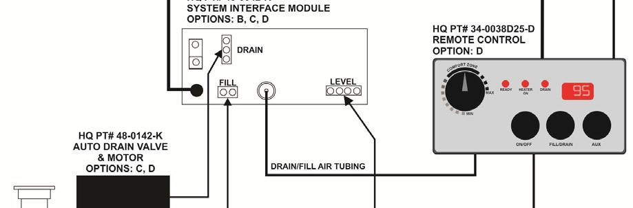
11 SYSTEM INTERFACE MODULE SEE NEXT PAGE 13 FOR IMPORTANT TIPS 10

12 HOLE DRILLING DIAGRAM 11
13 12
14 PLUMBING AND AUTO-FILL TIPS PLUMBING TIPS: MEASURE TWICE DRILL ONCE DRY-FIT PLUMBING BEFORE HOLES ARE DRILLED FLEXIBLE PVC SHOULD BE USED BETWEEN EQUIPMENT AND BAPTISTRY ALWAYS USE COMPATIBLE ADHESIVES AND PRIMERS AUTO-FILL VALVE TIPS: INSTALL PER PLUMING DIAGRAM VALVE ASSY CAN BE EFFECTED BY WEIGHT, SUPPORT IF NECESSARY FILL ASSY CAN BE PLUMBED VERTICALLY OR HORIZONTALLY TO BYPASS FILL VALVE LOSSEN SMALL BLACK SCREW NEXT TO SOLENOID AUTO-DRAIN VALVE TIPS: IF SYSTEM IS DRAINING AND FILLING AT THE SAME TIME FLIP TOGGLE SWITCH ON DRAIN VALVE TO OPPOSITE POSITION DO NOT ATTEMPT TO TURN VALVE BY HAND, PERMANENT DAMAGE WILL OCCURE. 13
 Control plugs into the receptacle on the side of the control box.")
15 EQUIPMENT DESCRIPTION WIDTH = 30 HEIGTH = 13 DEPTH = 15 CONTROL BOX The control box contains all the electrical components necessary to operate your tub, it also contains the field wiring compartment. The System Interface Module (DRAIN/FILL CONTROL) Control plugs into the receptacle on the side of the control box. GROUND FAULT CIRCUIT INTERRUPTER (GFCI) The GFCI is designed to provide protection against potential electrical shock hazard should a ground fault occur. The installation of a properly sized ground circuit and bonding circuit is still required as detailed in the electrical installation section of this manual. The GFCI in your installation may be installed at the electrical service panel, a separate sub panel, or built into the control box. Test the GFCI before each use and at least monthly when the tub is not being used regularly. 14
16 Test the GFCI as follows: 1. With the power on, push the test button; the reset button should pop out. Caution - If the GFCI fails to operate in this manner, do not use the tub until a qualified service technician has corrected the problem. 1. To restore power, push the red reset button in. THERMOSTAT Setting the thermostat controls the temperature of the water. The thermostat is located on the front of the control box. When the equipment is operating, the thermostat will control the heater. Initially, adjust the thermostat knob to the middle of the Comfort Zone. This setting will cause the water temperature to rise to approximately 80F (27C). Do not expect to feel hot water coming from the jets. The length of time it takes the water to reach desired temperature depends on several factors: water temperature at start, ambient air temperature, tub capacity, relative humidity, type and insulating qualities of a cover and the consistency of electric power applied. Any graduations on the scale around the thermostat are intended for reference only. They do not reflect the actual water temperature. Remember that a small change on the dial will yield a difference of several degrees, so make small adjustments until you find your preferred temperature. Allow several hours between adjustments for temperatures to stabilize. Use an accurate thermometer to monitor the water temperature. HEATER The stainless steel housing contains an electrical heating element and is fitted with a safety pressure switch that monitors water flow. The heater operates on demand at the power levels indicated in the table below. It will shut off when the thermostat setting is reached or the water ceases to flow. UModel Heater Voltage Heater Watts Breaker Size BES-6005/T-HC V 11.0 kw 60-80A BES-6000/T-HC V 5.5 kw 40-50A HIGH LIMIT The purpose of this switch is to shut off the heater if the water temperature within the heater reaches a factory-set, non-adjustable limit. After the water cools sufficiently, push to reset. If the switch trips repeatedly, do not use the tub until the problem has been identified and corrected by a qualified service technician. 15
17 2B SYSTEM INTERFACE RECEPTACLE & MODULE Provides for operation of Auto-Fill & Auto-Drain options when System Interface Module is installed. SYSTEM DIAGNOSTIC CENTER These indicators provide real time diagnostics of the system. HEATER ON Illuminated whenever the heater is activated PUMP ON Illuminated whenever the system pump is activated. SYSTE M FUSE Illuminated when the main system fuse is blown o Possible indication of pump issue. HIGH LIMIT TRIPPED Illuminated when the High-Limit safety switch is tripped o If the switch trips repeatedly do not use until corrective service is performed SYSTE M MIS-WIRE Illuminated when the system has been mis-wired o This is an indication the 120V has been sent up the Neutral line and is a protective feature. Have an electrician correct the issue to allow operation. TIMECLOCK (IF EQUIPPED) Provide timer control over heating and filtration cycles. To activate a timed cycle push the teeth on the timer outward, each tooth represent 2 hours of operation. The ( 2) modes of operation are based on the rocker switch under the timer and are as follows: 1. Timed Heat Mode: The system heats and filters based on the setting of the timer 2. Thermostatic Heat Mode: The pump comes on and off with relation to the thermostat. If a timed cycle occurs outside a heat call the pump will activate to provide additional filtration. SYSTEM START-UP 1. Turn the thermostat located on the control box to the off position. 2. Open all water valves, if equipped, on the inlet and/or outlet to allow water to flow into the equipment system. 3. Fill the tub to within 8 to 9 of the top, or as otherwise directed by the manufacturer. CAUTION: The equipment system must never be operated without water or serious damage to the heater and/or pump may result which can void the warranty. 4. Check all plumbing connections for leaks. 5. With the thermostat in the off position, apply power to the control box. Note: if the control box is equipped with a ground fault circuit interrupter, it may be necessary to press and release the red GFCI Reset button. IMPORTANT NOTE: It is most important that the pump be operated for several minutes to insure that all air has been removed from the system before the heater is allowed to operate. Only after full water flow has been established should the thermostat be turned up. 16
18 OPERATION Operating considerations for BES standalone (option A): 1. For initial start up turn thermostat all the way down and fill tub. 2. Insure that tub has water above highest return and open bleed valve on face of pump to bleed air from system. 3. Turn thermostat DOWN and turn on system power, the pump should activate and water should begin flowing. Allow pump to run until all air is purged from the unit 4. Turn the thermostat UP, the heat light on the front of the BES unit should illuminate. 5. Insure pressure switch is properly adjusted to allow heat function (Indicator will light for heat). 6. Before draining insure that power has been removed from the control. Operating considerations for BES with Auto Fill (option B): 1. Insure that SYSTEM INTERFACE MODULE (DRAIN/FILL CONTROL) option control is securely plugged into BES receptacle. Install air tubing and air button on the On/Off air switch nipple. 2. Set thermostat all the way down and apply power to unit. If fill valve does not open and begin filling the tub then press the air button supplied one time. 3. Once the unit is full the fill valve will automatically close, the pump will engage and the unit should be ready for heating once air is purged from the system (pressure switch may require some adjustment). 4. Turn the thermostat knob clockwise until the heat engages and set for desired temperature. The pump will continue to run as long as tub is full and power is applied. 5. Before draining unit insure that the auto fill has been deselected (press button once) or that power is removed from BES. Operating considerations for BES with Auto Fill/Auto Drain (option C): 1. Insure that SYSTEM INTERFACE MODULE (DRAIN/FILL CONTROL) option is securely plugged into matching receptacle and that Auto-Drain valve cord is installed. Install one set of air tubing and air button on the On/Off air switch nipple on the control system and one set on the Fill/Drain air switch nipple on the Interface Module. 2. Set the thermostat all the way down and apply power to unit. If neither drain nor fill valves actuate press On/Off button once. If drain valve starts to open press Fill/Drain button once after valve reaches full open. Once Fill/Drain is in the correct position the drain valve should close and the fill valve should open filling the tub. 3. Once the tub is full the fill valve will automatically close, the pump will engage and the unit should be ready for heating once air is purged from the system (pressure switch may require some adjustment). 4. Turn the thermostat clockwise until the heat engages and set for desired temperature. The pump will continue to run as long as tub is full and power is applied. 5. To drain press the Fill/Drain button once. After the unit is drained press On/Off button once to insure that no inadvertent filling or draining can take place. ***Once Fill or Drain is selected you must allow drain valve to travel completely before switching back or the actuator may stick half way requiring power to be recycled*** 17
19 Operating considerations for BES with Remote Control Auto Fill/Drain (option D): 1. Insure that SYSTEM INTERFACE MODULE (DRAIN/FILL CONTROL) option is securely plugged into BES receptacle and that Auto-Drain valve cord is installed. Install one set of air tubing and air button from Remote Control on the On/Off air switch nipple and one set on the Fill/Drain air switch nipple. 2. Insure Remote Control is plugged into receptacle from option control and that both thermostats on BES and Remote Control are set to minimum (fully CCW). 3. Apply power and if no lights appear on Remote Control press On/Off button once. If drain light illuminates wait for valve to finish rotating and then press Fill/Drain button once. If fill light is lit allow unit to fill normally. 4. The unit is full once the digital display appears on Remote Control. Pump will engage and the unit should be ready to heat once air is purged (pressure switch may require adjustment). 5. Turn the Remote Control thermostat clockwise until the heat light on the Remote Control engages and set dial for desired temperature. The pump will continue to run as long as tub is full and power is applied. 6. Once temp is reached the fill light will again appear, heat light will be off and the digital display will display actual temperature. Pump will continue to run. 7. To drain press Fill/Drain once. Indicators should switch from fill or heat to drain and temp display will be blank. Pump will stop. 8. Once the tub is empty press On/Off until all indicators are off to insure no inadvertent filling or draining can take place. ***Once Fill or Drain is selected you must allow drain valve to travel completely before switching back or the unit may stick half way requiring power to be recycled*** Heater Pressure Switch adjustment: With pump running and thermostat calling for heat if no heat indicator is illuminated perform the following: 1. Insure flow is moving into tub from equipment and that no air bubbles are present at tub return fitting (if air present open pump bleed valve on face to let air escape). 2. Insert flat tip screwdriver into slot on top of pressure switch and adjust CCW until heat engages (if heat indicator flickers continue adjusting until it remains steady). 3. Once heat indicator remains on steadily adjust the pressure switch knob an additional ½ turn CCW. Turn OFF power and remove pump output wire (black or white wire) from back of pump motor and insure it is isolated before re-energizing power. Insure that heat indicator does not come on with the thermostat turned up. If indicator does illuminate immediately disconnect power, reconnect pump, and repeat steps
20 Equipment system will not operate: PROBLEM SOLVING 1. Make sure the Power Air Switch is turned ON 2. Check the Ground Fault Circuit Interrupter, if equipped, to see if the reset button has popped out. If it has, press reset button inward. If the GFCI trips repeatedly, contact a service technician to correct the problem. 3. Check the main circuit breaker panel. If the circuit breaker has tripped reset the breaker. If the circuit breaker trips repeatedly, contact a service technician to correct the problem. 4. For cord connected units check the receptacle. 5. Make sure the high-limit has not tripped. Push to reset. Pump will run but there is no water flow: 1. Make sure system is installed below water level. 2. Make sure all valves are in the open position. 3. Make sure that the filter is clean. 4. Check the suction fittings to make sure that they are not clogged with debris. 5. Check the water level and make sure it is above the jets and at the proper level on the skimmer opening. 6. Check the pump for trapped air. With the pump running, loosen the pump bleed screw to release any trapped air. When there is water flow to the jets tighten the bleed screw securely. You may need to use a sponge to collect the water from the bleed screw. Pump runs and there is water flow but no heat: 1. Turn the thermostat to a higher temperature setting. Do not expect to feel hot water coming from the jets. 2. Check to see if the high limit switch reset button, located on the front of the control box, has popped outward. If so, reset by pressing inward. 3. Check to make sure that all the valves are open and that there is full flow. Limited water flow may not activate the pressure switch to allow the heater to come on. The water will not maintain the proper temperature: 1. A thermal cover is required to maintain the water temperature. 2. Turn the thermostat to a higher setting. 19
21 3BLimited Warranty Hydroquip, Inc. warrants these products to be free from defects in material and workmanship for a period of 1 year from the date of purchase (DOP), under the following provisions: From DOP to date of installation (Not to exceed 10 working days after DOP), products suspected of failure at time of installation may receive a replacement of component or like product if evaluated by Hydroquip Technical Support with an authorized service professional at the job site. Hydroquip, Inc. will not cover failure due to improper installation, unauthorized modification, negligence, abuse, misuse, or misapplication. Product failure after installation and up to 30 days from DOP may receive a component replacement if evaluated by Hydroquip Technical Support and an authorized service professional at the job site. Hydroquip, Inc. will not warrant heater elements, heater assemblies with short to ground, fuses, optional controls, or damaged related to freezing, water chemistry, unauthorized modification, negligence, abuse, misuse, or misapplication. Product failure after 30 days and up to 1 year from DOP will be repaired or replaced at our option. Hydroquip, Inc. will not warrant heater elements, heater assemblies with short to ground, fuses, or damaged related to normal wear and tear, freezing, water chemistry, unauthorized modification, negligence, abuse, misuse, or misapplication. This warranty extends only to the normal, personal use by the original retail purchaser. The warranty does not cover any commercial use of this product in any way. Pump seals, O-Rings, gaskets, are not covered by the Hydroquip, Inc. warranty during the first 12 months of the warranty period. Some items furnished by Hydroquip, Inc., such as spa-side controls, may be made by other manufacturers who might have longer warranty periods. Hydroquip, Inc. will not be responsible for labor incurred in removing, inspecting, repairing, or reinstalling this product. Hydroquip, Inc. will not be responsible for labor incurred for routine maintenance, adjustments, or alterations to the calibration of electrical components. Resellers of Hydroquip, Inc. equipment may request pre-authorization to return a product that is claimed to be defective by calling or faxing The authorized service agent must ship the product freight prepaid to Hydroquip, 510A N. Sheridan St. Corona, CA Upon repair or replacement the product will be returned to the sender freight collect. When sent to Hydro-Quip, the product must be accompanied by the sales receipt or other proof of the purchase date as well as the sender s name, mailing address, daytime phone number, and any other information relating to the claim. Unless state law expressly provides otherwise, Hydroquip, Inc. will only be responsible for repair or replacement of its products that are found to be defective as provided above, and will not bear the cost of any incidental or consequential damages. This warranty gives you specific legal rights and you may also have other rights that vary from state to state. 20
22 21
23 22
24 23
Spa Control System OWNER S MANUAL
 LIMITED WARRANTY ONE YEAR LIMITED WARRANTY: UNITED SPAS, INC. warrants, to the original purchaser, the Spa Equipment against defects in materials or workmanship for a period of one year from date of purchase.
TRANQUILITY ADVANCED HEATING SYSTEM
 TRANQUILITY ADVANCED HEATING SYSTEM MODELS: PBES-6010 PBES-6040 1000W Advanced Heating System 4000W Advanced Heating System Operation / Installation Instructions 85-0059-G Rev.03-6/13 INTRODUCTION The
Installation, Operation & Service Procedures
 Installation, Operation & Service Procedures Baptistry Heater System Model EQAS-CH HEATER ONLY PT#: 04-10029 REV.02 85-0139-C 08/12 TABLE O CONTENTS TABLE O CONTENTS/WARRANTY 1 IMPORTANT SAETY INSTRUCTIONS
4230/6230/9230 SERIES OWNERS OPERATION GUIDE
 4230/6230/9230 SERIES OWNERS OPERATION GUIDE 104 CONTENTS Important Safety Instructions 2 INTRODUCTION Major Component Illustration 4 SYSTEM OPERATION Features & Function Visual Diagnostic System (VDS)
ULT L IMAT A E SERIES SOLID-STA T T A E SYSTEM OPERAT A ION MANUAL 8600
 ULTIMATE SERIES SOLID-STATE SYSTEM OPERATION MANUAL 8600 CONTENTS Important Safety Instructions 2 INTRODUCTION Major Component Illustration 4 SYSTEM OPERATION Heater Operation Spaside Control Spa Light
UNIVERSAL AIR SERIES SYSTEM OPERATION MANUAL
 UNIVERSAL AIR SERIES SYSTEM OPERATION MANUAL CONTENTS Important Safety Instructions 2 INTRODUCTION Major Component Illustration 4 SYSTEM OPERATION Illustration System Mis-Wire System Over Temperature System
6500/7500 SERIES OWNERS OPERATION GUIDE
 6500/7500 SERIES OWNERS OPERATION GUIDE CONTENTS Important Safety Instructions Introduction 2 4 FEATURES & FUNCTION Ground Fault Circuit Interrupter (GFCI) Heater On Indicator Spaside Control Setting Filtration
UNIVERSAL TEE STYLE Hydromassage Bath Heater INSTALLATION INSTRUCTIONS
 UNIVERSAL TEE STYLE Hydromassage Bath Heater INSTALLATION INSTRUCTIONS This Manual Covers: 7 Models SG100-15UP - 120V, 1500W SG202-20UP - 240V, 2000W CARTON CONTENTS: A - One (1) Whirlpool Bath Heater
4230/6230/9230 SERIES OWNERS OPERATION GUIDE
 4230/6230/9230 SERIES OWNERS OPERATION GUIDE CONTENTS Important Safety Instructions 2 INTRODUCTION Major Component Illustration 4 SYSTEM OPERATION Features & Function Visual Diagnostic System (VDS) Spaside
SPA HEATER INSTALLATION, OPERATION AND MAINTENANCE
 SPA INSTALLATION, OPERATION AND MAINTENANCE MODELS: ST SERIES 5.5 & 11kW 240V SINGLE PHASE BEFORE YOU BEGIN CHECK ALL ELECTRICAL CONNECTIONS TO ALL COMPONENTS WITHIN THE FOR TIGHTNESS. CONNECTIONS CAN
4200/6200/9200 SERIES
 4200/6200/9200 SERIES OWNERS OPERATION GUIDE 85-0063-A Rev 9 04/09 CONTENTS Important Safety Instructions 2 INTRODUCTION Major Component Illustration 4 SYSTEM OPERATION Features & Function Visual Diagnostic
OWNERS OPERATION GUIDE
 4220/6220/9220 SERIES OWNERS OPERATION GUIDE CONTENTS Important Safety Instructions 2 INTRODUCTION Major Component Illustration 4 SYSTEM OPERATION Features & Function Visual Diagnostic System (VDS) Spaside
4100/6100/7100 SERIES OWNERS OPERATION GUIDE
 4100/6100/7100 SERIES OWNERS OPERATION GUIDE CONTENTS Important Safety Instructions 2 INTRODUCTION Major Component Illustration 4 SYSTEM OPERATION Features & Function Visual Diagnostic System (VDS) Spaside
4200/6200/9200 SERIES OWNERS OPERATION GUIDE
 4200/6200/9200 SERIES OWNERS OPERATION GUIDE CONTENTS Important Safety Instructions 2 INTRODUCTION Major Component Illustration 4 SYSTEM OPERATION Features & Function Visual Diagnostic System (VDS) Spaside
ELECTRIC SPA-PAK HEATER INSTALLATION & OPERATING INSTRUCTIONS
 ELECTRIC SPA-PAK HEATER INSTALLATION & OPERATING INSTRUCTIONS CATALOG NO.: 6100.53O Effective: 03-15-05 Replaces: 02-01-05 INTRODUCTION The SPA-PAK Spa Heaters have been designed to provide efficient,
6000 AIR SERIES SYSTEM OPERATION MANUAL A-AZ Rev.0 5/07
 000 AIR SERIES SYSTEM OPERATI MANUAL -00A-AZ Rev.0 /0 CTENTS NOTES Important Safety Instructions INTRODUCTI Major Component Illustration SYSTEM OPERATI Illustration GFCI (Ground Fault Circuit Interrupter)
INSTALLATION, OPERATION AND MAINTENANCE
 POOL HEATER INSTALLATION, OPERATION AND MAINTENANCE MODELS: PHS-CN SERIES, 5, 8, 4, 0, 6, 45, 54 & 57kW 08V, 40V, 480, 600V SINGLE & THREE PHASE BEFORE YOU BEGIN CHECK ALL ELECTRICAL CONNECTIONS TO ALL
POOL HEATER INSTALLATION, OPERATION AND MAINTENANCE
 POOL HEATER INSTALLATION, OPERATION AND MAINTENANCE MODELS: TR SERIES, 5 & 8kW 08V, 40V, 480V, 600V BEFORE YOU BEGIN CHECK ALL ELECTRICAL CONNECTIONS TO ALL COMPONENTS WITHIN THE HEATER FOR TIGHTNESS.
Whirlpool Bathtub Model Number: MT618
 INSTALLATION AND OWNER'S MANUAL Whirlpool Bathtub Model Number: MT618 Please carefully read these instructions before you begin to install the products. 07/11 Rev A P/N:100056-03 Thank you for purchasing
LEVENS STEAM SHOWER ENCLOSURE
 LEVENS STEAM SHOWER ENCLOSURE INSTALLATION AND USER MANUAL CONTENTS Steam Shower Enclosure Installation...2 Technical Information...2 Plumbing Requirements...2 Assembly...3 Tools and Materials...3 Installation...3
INSTALLATION/OPERATING INSTRUCTIONS. AQUEFIER POOL HEATERS Model TK125T
 INSTALLATION/OPERATING INSTRUCTIONS FOR AQUEFIER POOL HEATERS Model TK125T Trevor-Martin Corp., 4151 112 th Terrace North, Clearwater, FL 33762 Bulletin PH-125T Rev. 3 1 IMPORTANT SAFETY INSTRUCTIONS READ
ARLEY STEAM SHOWER ENCLOSURE
 ARLEY STEAM SHOWER ENCLOSURE INSTALLATION AND USER MANUAL CONTENTS Steam Shower Enclosure Installation...2 Technical Information...2 Plumbing Requirements...2 Assembly...3 Tools and Materials...3 Installation...3
NEXT SOLID-STATE SYSTEM. P u m p. * A u x. e f
 e f s a i ECO-1 SERIES SOLID-STATE SYSTEM OPERATION MANUAL P u m p * Pum p 2 1 * A i r Light POWER CONTROL SWITCH Ref r to Oper tion Ma nual o r test ng and operational p r o c e d u r e c System V D S
CONTENTS CONSIDERATIONS. General Plumbing Component Connection ILLUSTRATION. Control System CONFIGURATION. Voltage Verification CONNECTION
 AIR SERIES SYSTEM INSTALLATION MANUAL CONTENTS CONSIDERATIONS General Plumbing Component Connection 2 2 2 ILLUSTRATION Control System 3 CONFIGURATION Voltage Verification 4 CONNECTION Component Connection
FREWIN STEAM SHOWER ENCLOSURE
 FREWIN STEAM SHOWER ENCLOSURE INSTALLATION AND USER MANUAL CONTENTS Steam Shower Enclosure Installation...2 Technical Information...2 Plumbing Requirements...2 Assembly...3 Tools and Materials...3 Installation...3
ECO SPA & POOL OWNERS MANUAL & INSTALLATION GUIDE
 ECO SPA & POOL OWNERS MANUAL & INSTALLATION GUIDE MODELS: ECO SPA 5.5-11 / ECO POOL 18-27 IMPORTANT SAFETY INSTRUCTIONS,INSTALLATIONIN STRUCTIONS,USER INSTRUCTIONS As when installing or using any high
INSTALLATION, OPERATION AND MAINTENANCE
 INLINE HEATER INSTALLATION, OPERATION AND MAINTENANCE MODELS: ILS SERIES 1.5kW 120V SINGLE PHASE BEFORE YOU BEGIN CHECK ALL ELECTRICAL CONNECTIONS TO ALL COMPONENTS WITHIN THE HEATER FOR TIGHTNESS. CONNECTIONS
IMPORTANT SAFETY INSTRUCTIONS READ AND FOLLOW ALL INSTRUCTIONS SAVE THESE INSTRUCTIONS
 IMPORTANT LEAVE THESE INSTRUCTIONS WITH THIS UNIT Whirlpool / Chromatherapy / BubbleAir Operating Instructions IMPORTANT SAFETY INSTRUCTIONS READ AND FOLLOW ALL INSTRUCTIONS SAVE THESE INSTRUCTIONS INSTRUCTIONS
Owner s Manual. Model PH050006
 Owner s Manual Model PH050006 Manufactured By: Shanghai Qinxu Plastics Products Co., Ltd. No. 5151, Dongchuan Road Heqing Town, Pudong New Area Shanghai, CN 201201 IMPORTANT SAFETY INSTRUCTIONS The following
SYSTEM BASIC WHIRLPOOLS
 SYSTEM BASIC WHIRLPOOLS 114847-2-CB 2000 Kohler Co. IMPORTANT SAFETY INSTRUCTIONS ATTENTION INSTALLER: INSTRUCTIONS PERTAINING TO RISK OF FIRE, ELECTRIC SHOCK, OR INJURY TO PERSONS READ AND FOLLOW ALL
DRAFT INSTALLATION INSTRUCTIONS. Solid-State Series !! NOTE!! Covers the following models: Refer to INSERT for additional information
 INSTALLATION INSTRUCTIONS Solid-State Series!! NOTE!! Covers the following models: " CS6100 - CS7100 " CS6200 - CS9200 " CS6220 - CS9220 " CS6230 - CS9230 " CS6500 - CS7500 " CS6330 - CS9300 " CS9400 -
Installation and user s manual Read carefully and keep it for later reference
 For ASPEN / MALIBU / MONTANA / ROVER / SILVER spa Installation and user s manual Read carefully and keep it for later reference IMPORTANT SAFETY INSTRUCTIONS For your own safety and that of your product,
Whirlpool Tub USER S MANUAL
 Whirlpool Tub USER S MANUAL Model: PH050006/PH050011, 110V~, 60Hz, 1500W BLUE WAVE PRODUCTS 1745 WALLACE AVE. ST. CHARLES, IL 60174 Read this manual before operation IMPORTANT SAFETY INSTRUCTIONS WARNING1:
IMPORTANT SAFETY INSTRUCTIONS EC-AG1-25 EC-AG1, EC-AG2 SAVE THESE INSTRUCTIONS.
 IMPORTANT SAFETY INSTRUCTIONS 2 1. Read and Follow All Instructions 2. Read this manual completely before attempting installation. 3. All permanent electrical connections should be made by a qualified
ULTIMATE SERIES SOLID-STATE
 ULTIMATE SERIES SOLID-STATE SYSTEM OPERATION MANUAL Pump 1 Light P ump2 (Optio nal) Air Ozone POWER C O N T R O L SWITCH RefertoOperation Manual for testing andoperational proc edures P ump3 Cr ic. H igh
SPA BLOWER OWNER'S MANUAL XXXX, XXXX, XXXX, XXXX, XXXX, XXXX fax
 SPA BLOWER OWNER'S MANUAL 80015-XXXX, 80016-XXXX, 80017-XXXX, 80018-XXXX, 80019-XXXX, 80020-XXXX fax 888.610.3839 2015 323300-015 6/15 THIS PAGE INTENTIONALLY LEFT BLANK. 2 Operating Instructions and Parts
Installation and Operation Manual MG-304. Please read this manual carefully before use.
 Installation and Operation Manual MG-304 Please read this manual carefully before use. 1 P a g e Important Safety Instructions: Warning! Use this unit only for its intended purposes or as described in
2 SPEED PUMP INSTRUCTION MANUAL READ THIS MANUAL CAREFULLY BEFORE USING YOUR 2 SPEED PUMP
 2 SPEED PUMP INSTRUCTION MANUAL READ THIS MANUAL CAREFULLY BEFORE USING YOUR 2 SPEED PUMP 8308 PUMP PARTS BREAKDOWN Ref # Part # Manf. # Descrip on 1 NEP2134 AC 81361 PUMP LID 2 NEP2135 AC 81396 PUMP LID
AWP 3260 CWH Installation Instructions Hydro-massage Bathtub - UL 1795
 Tools you might need for proper installation galvanized nails or screws large level hammer or screw gun shims adhesive Thank you for purchasing Praxis Bathware. For best results, please read and follow
INFRARED WOODEN SAUNA ROOM INSTRUCTION MANUAL IG-530 BH
 INFRARED WOODEN SAUNA ROOM INSTRUCTION MANUAL Read all instructions carefully before using the wooden infrared sauna room IG-530 BH PRECAUTIONS FOR USE...1 PARTS NAMES...2 READ BEFORE INSTALLATION...3
IMPORTANT INSTALLATION and OPERATING INSTRUCTIONS
 IMPORTANT INSTALLATION and OPERATING INSTRUCTIONS To be provided to the Walk-In Tub owner/user. INSTRUCTIONS PERTAINING TO A RISK OF FIRE, ELECTRIC SHOCK OR INJURY TO PERSONS IMPORTANT SAFETY INSTRUCTIONS
DUAL SUBMERGED SUCTION OUTLET SET. [Commonly called main drains] Owner s Manual
![DUAL SUBMERGED SUCTION OUTLET SET. [Commonly called main drains] Owner s Manual](/thumbs/87/97370711.jpg "DUAL SUBMERGED SUCTION OUTLET SET. [Commonly called main drains] Owner s Manual") ISDUALSWG Rev G DUAL SUBMERGED SUCTION OUTLET SET [Commonly called main drains] Owner s Manual Contents Product Warnings. Introduction..... 3 Installation... 4 Replacement Parts.. 5 General Warnings. 6
ISDUALSWG Rev G DUAL SUBMERGED SUCTION OUTLET SET [Commonly called main drains] Owner s Manual Contents Product Warnings. Introduction..... 3 Installation... 4 Replacement Parts.. 5 General Warnings. 6
INSTALLATION & INSTRUCTION MANUAL
 INSTALLATION & INSTRUCTION MANUAL CONTENTS TUFF SPA INSTALLATION REQUIREMENTS........3 IMPORTANT SAFETY INSTRUCTIONS... 4 WARNINGS... 5 IMPORTANT CAUTION... 6 WIRING DIAGRAM... 7 110v to 220v CONVERSION...
Introduction. Spa Model: Power Pack Model: Serial #:
 Introduction Congratulations on your purchase of the finest whirlpool spa on the market today. Emerald Spa Corporation welcomes you to the Emerald Whirlpool Spa Life-style! We are confident that this purchase
DELUXE SERIES SOLID-STATE
 c d u o s e n DELUXE SERIES SOLID-STATE SYSTEM OPERATION MANUAL Pump 1 Light Pump ( Op tional) A i r Ozone POWER CONTROL SWITCH R et f eo r t O p r a i n Manual for testi g a nd operational p r o e r e
Sundance Spas SPA EQUIPMENT SYSTEM. Installation Instructions. P/N Rev. A
 Sundance Spas SPA EQUIPMENT SYSTEM Installation Instructions P/N 6530-456 Rev. A Contents Important Notices 1 Important Safety Instructions 2 Where to Place the Equipment System 3 Connecting Pipes Between
Owner s Manual for the Passport Series Rooms PS 44 With SaunaLogic Control
 Owner s Manual for the Passport Series Rooms PS 44 With SaunaLogic Control Precautions before Use. 2 Read Before Installation... 3 Room Assembly 4 Lighting Operation 10 Sauna Heater Operation 11 Maintenance..
MAXI PUMP INSTRUCTION MANUAL NE6151B /NE6171B READ THIS MANUAL CAREFULLY BEFORE USING YOUR MAXI PUMP
 MAXI PUMP INSTRUCTION MANUAL NE6151B /NE6171B READ THIS MANUAL CAREFULLY BEFORE USING YOUR MAXI PUMP 8104 MAXI-PUMP PARTS BREAKDOWN Re f # 1 2 3 4 5 6 7a 7b 8 9 10 11 12 13 14 15 16 2 Part # NEP2134 NEP2135
TIDALWAVE I/G POOL PUMP INSTRUCTION MANUAL
 TIDALWAVE I/G POOL PUMP INSTRUCTION MANUAL READ THIS MANUAL CAREFULLY BEFORE USING YOUR PUMP 88 PUMP PARTS BREAKDOWN REF # Order # Mfr # Description 1 NEP4 AC 348 Lid Knobs NEP AC 380 Strainer Lid 3 NEP6
HELO FAR-INFRARED CABIN INSTRUCTION MANUAL HSI 40 CE
 HELO FAR-INFRARED CABIN INSTRUCTION MANUAL Read all instructions carefully before using the infrared cabin HSI 40 CE PRECAUTIONS FOR USE...1 PARTS NAMES...2 READ BEFORE INSTALLATION...3 INSTALLATION OF
HELO FAR-INFRARED CABIN INSTRUCTION MANUAL HSI10
 HELO FAR-INFRARED CABIN INSTRUCTION MANUAL Read all instructions carefully before using the infrared cabin HSI10 PRECAUTIONS FOR USE...1 PART LIST...2 READ BEFORE INSTALLATION...3 INSTALLATION OF THE CABIN...4-7
Important Installation Guide & Operating Instruction
 Important Installation Guide & Operating Instruction To be removed for use by the occupant Packing Slip Included: 1. Faucets & Valves 2. Riser Rod 3. Shower Rod & Curtain 4. Grab Bar 5. Quick Hose 6. Front
INFRARED WOODEN SAUNA ROOM INSTRUCTION MANUAL IG-670EX/E300-CX
 INFRARED WOODEN SAUNA ROOM INSTRUCTION MANUAL Read all instructions carefully before using the wooden infrared sauna room IG-670EX/E300-CX PRECAUTIONS FOR USE...1 PARTS NAMES...2 READ BEFORE INSTALLATION...3
USER MANUAL
 USER MANUAL 1 Contents Content Page Number Warning 3-4 Caution Notice 5 Installation Notice 6 Assembly 7-9 Operation 10 Maintenance of water in the water tank body 13 Maintaining water 14 Cleaning the
champion spas OWNERS MANUAL
 champion spas OWNERS MANUAL Model: Serial Number: Date Installed: Dealer: Address: Telephone: Note: The serial number/identification label is located within the equipment compartment and skimmer housing.
INSTALLATION AND OPERATING INSTRUCTIONS Page 1
 INSTALLATION AND OPERATING INSTRUCTIONS Page 1 Do not take a sauna if using alcohol, drugs or medications. Pregnant women or persons with poor health should consult their physician before using any sauna.
Destination Collection Whirlpool Bath Installation Instructions
 Tools you might need for proper installation Galvanized Nails or Screws Large Level Hammer or Screw Gun Shims Adhesive Thank you for purchasing Praxis Bathware. For best results, please read and follow
CERTIFICATE OF AUTHENTICITY
 CERTIFICATE OF AUTHENTICITY Thank you for your purchase. This certificate hereby verifies that the spa you have purchased from an Artesian Spas (May Manufacturing, LLC) authorized dealer is authentic,
Ozone + UV Sanitation
 Ozone + UV Sanitation Installation Manual 4-2177-01 Rev.C IMPORTANT SAFETY INSTRUCTIONS When installing and operating the DEL Spa Solar Eclipse, basic precautions should always be followed: READ AND FOLLOW
Next Generation Corona Discharge Installation & Operation Manual
 Next Generation Corona Discharge Installation & Operation Manual 4-2319-01 Rev.A IMPORTANT SAFETY INSTRUCTIONS READ & FOLLOW ALL INSTRUCTIONS Read this manual completely before attempting installation.
HELO FAR-INFRARED CABIN INSTRUCTION MANUAL HSI80
 HELO FAR-INFRARED CABIN INSTRUCTION MANUAL Read all instructions carefully before using the infrared cabin HSI80 PRECAUTIONS FOR USE...1 PARTS NAMES...2 READ BEFORE INSTALLATION...3 INSTALLATION OF INFRARED
1, 2, & 4. Corona Discharge Ozone Generators INSTALLATION & OPERATION MANUAL. DEL Ozone SAN LUIS OBISPO, CA USA Fax:
 1, 2, & 4 Corona Discharge Ozone Generators INSTALLATION & OPERATION MANUAL DEL Ozone SAN LUIS OBISPO, CA 93401 USA 800-676-1335 Fax: 805-541-8459 111904 / 4-0308 Rev. F Table of Contents SECTION 1 General
AQUA-FLO A SERIES. The Bronze Pump designed exclusively for any swimming pool or spa application.
 The Bronze Pump designed exclusively for any swimming pool or spa application. The A Series pump, including motor bracket, impeller, volute and trap, are unit cast from corrosion-resistant fine old world
AIR SWITCH CONTROL 110/220 VOLT PART NUMBER # A5500 OWNER S MANUAL SAVE THIS INSTRUCTION MANUAL
 ADVANTAGE SPA CONTROLS AIR SWITCH CONTROL 110/220 VOLT PART NUMBER # A5500 OWNER S MANUAL To prevent potential injury and to avoid unnecessary service calls, read this manual carefully and completely.
INSTALLATION MANUAL SPA HIGH OFF LOW POOL HEATER AUX 1 AUX 2
 INSTALLATION MANUAL SPA HIGH OFF ON ON Switch LOW POOL HEATER AUX 1 AUX 2 Important Safety Precautions When installing and using this electrical equipment, basic safety precautions should always be followed,
Homeowners Guide. Bath Whirlpools
 Homeowners Guide ath Whirlpools K-1106, K-1109, K-1112, K-1114, K-1122, K-1124, K-1126, K-1131, K-1139, K-1144, K-1146, K-1148, K-1151, K-1154, K-1157, K-1160, K-1162, K-1164, K-1192, K-1194, K-1196, K-1198,
Installation & operating instructions
 Installation & OPERATING INSTRUCTIONS Installation & operating instructions MODEL 2747SEN Meditub 5701 NW 35 Avenue Miami, FL 33142 Phone 866-633-4882 Fax 866-560-1060 info@meditub.com http://www.meditub.com
Instruction Manual. Pressure Washer. Get ready to deep clean! Wards.com Wards.com ITEM:
 Get ready to deep clean! Pressure Washer Montgomery Ward Customer Service 3650 Milwaukee Street, Madison, WI 53714 8:00 am to Midnight, Monday through Friday Wards.com Instruction Manual ITEM: 751821 Wards.com
MCD. Corona Discharge Ozone Generators MANUFACTURED BY Bullock Lane San Luis Obispo, CA
 MCD Corona Discharge Ozone Generators MANUFACTURED BY 3428 Bullock Lane San Luis Obispo, CA 93401 4-0622 Copyright 2005 DEL Ozone, Inc. IMPORTANT SAFETY INSTRUCTIONS When installing and using DEL Models
Ella Gel Coat Walk In Tub E SERIES OWNER'S MANUAL
 Ella Gel Coat Walk In Tub E SERIES OWNER'S MANUAL REPRESENTING THESE MODEL NUMBERS: 26 x 52 E2645SL / E2645SR SOAKING E2645AL / E2645AR AIR MASSAGE E2645DL / E2645DR DUAL MASSAGE 30 x 48 E3048SL / E3048SR
Typical Installation Breaker Box Class A 50 amp, 120/240 volt, GFCI
 READ THIS FIRST!!!! TYPICAL GFCI INSTALLATION GUIDELINES ATTENTION ELECTRICIAN: All PDC Spa Units must be installed with an approved G.F.C.I. in accordance with all applicable codes. Installation of G.F.C.I.
INFRARED WOODEN SAUNA ROOM INSTRUCTION MANUAL IG-540BX/B400-X. Important: Please record your serial number here
 INFRARED WOODEN SAUNA ROOM INSTRUCTION MANUAL Read all instructions carefully before using the wooden infrared sauna room IG-540BX/B400-X Important: Please record your serial number here TIP AND TRICKS...1
Spa Pool USER S MANUAL
 Spa Pool USER S MANUAL Model: TEKAPO, HAWEA, 220-240V~, 50Hz, 1800W, Class II Read this manual before operation WARRANTY All ezispa units are covered by a 12 month RETURN TO BASE warranty. It is the owners
Quick Start Guide. For product manuals and further installation / operation procedures visit
 Quick Start Guide For product manuals and further installation / operation procedures visit www.aquacal.com Important Read This Guide Before Installing or Operating Heat Pump LTP0093 Rev 1 03/21/2014 Page
O W N E R S M A N U A L
 cottage spas OW N E R S M A N UA L Model: Serial Number: Date Installed: Dealer: Address: Telephone: Note: The serial number/identification label is located within the equipment compartment and skimmer
B.I.C.A Built-In Coffee Appliance
 B.I.C.A Built-In Coffee Appliance Automatic Coffee Brewer Parts & Service Models: 1033510, 1033510S & 1033511 3828 S. Main St. Los Angeles, CA 90037-1491 800-421-6860 310-787-5444 Fax 310-787-5412 e-mail:
AirBath Hydro-Massage Tubs UL1795 Installation and Operating Instructions
 Tools you might need for proper installation Galvanized Nails or Screws - For Units with a Tiling Flange Four Foot Level Shims Caulking Gun Screw Gun Adhesive Thank you for purchasing the Praxis AirBath
INSTALLATION AND OPERATING INSTRUCTIONS
 Page 1 WARNING Do not take a sauna if using alcohol, drugs or medications. Pregnant women or persons with poor health should consult their physician before using any sauna. Designer Trend" Series Sauna
Owner s Manual. For all 1998 Bullfrog Portable Spas TABLE OF CONTENTS. (Multiple Patents Pending) IMPORTANT SAFETY INSTRUCTIONS
 IMPORTANT SAFETY INSTRUCTIONS") TABLE OF CONTENTS IMPORTANT SAFETY INSTRUCTIONS U.L. Safety Instructions... P. 02 Additional Safety Instructions... P. 04 Owner s Manual For all 1998 Bullfrog Portable Spas (Multiple Patents Pending) UPGRADES
TABLE OF CONTENTS IMPORTANT SAFETY INSTRUCTIONS U.L. Safety Instructions... P. 02 Additional Safety Instructions... P. 04 Owner s Manual For all 1998 Bullfrog Portable Spas (Multiple Patents Pending) UPGRADES
Laurel Mountain Whirlpools. Walk-In Bathtub Installation Manual
 Laurel Mountain Whirlpools Walk-In Bathtub Installation Manual IMPORTANT SAFETY INSTRUCTIONS PLEASE READ AND FOLLOW ALL INSTRUCTIONS PROVIDED CAREFULLY Install to permit access for servicing An equipment
FLCH4R Garage and Utility Electric Heater
 FLCH4R Garage and Utility Electric Heater Installation, Operation & Maintenance Instructions Model No. Volts Amps Watts BTU/HR Phase High Low High Low High Low Min Fuse Size* FLCH4R 208 17.3 8.66 3600
OWNER S MANUAL 1-2 PERSON SAUNA
 Rev. 9/5, Ver. 5 OWNER S MANUAL -2 PERSON SAUNA WITH CARBON HEATERS SA2402 TABLE OF CONTENTS ASSEMBLY TIPS & WARNINGS PARTS IDENTIFIER ASSEMBLY INSTRUCTIONS OPERATION INSTRUCTIONS ENJOYING YOUR SAUNA HEALTH
M770 ph Controller Owner s Manual
 M770 ph Controller Owner s Manual Table of Contents I. Introduction page 2 A. Water Chemistry page 2 B. Safety page 3 C. System Components page 4 D. Specifications page 7 E. Controller Panel Descriptions
Three Phase Simplex. Installation (937) Installation Instructions and Operation/Troubleshooting Manual. Installation of Floats.
 Installation Instructions and Operation/Troubleshooting Manual. Installation of Floats.") Three Phase Simplex Installation Instructions and Operation/Troubleshooting Manual This control panel must be installed and serviced by a licensed electrician in accordance with the National Electric Code
Three Phase Simplex Installation Instructions and Operation/Troubleshooting Manual This control panel must be installed and serviced by a licensed electrician in accordance with the National Electric Code
OPERATORS MANUAL FOR Mi-T-M CORONA DISCHARGE OZONE GENERATORS
 OPERATORS MANUAL FOR Mi-T-M CORONA DISCHARGE OZONE GENERATORS CAUTION RISK OF INJURY! READ MANUAL BEFORE OPERATING! This manual is an important part of the Corona Discharge Ozone Generator and must remain
SK SERIES INSTALLATION INSTRUCTIONS 1
 Certified Products PO Box 636 Eagle Idaho USA. 83616 T: 877.467.2862 F: 208.286.0290 info@scandiamfg.com www.scandiamfg.com SK SERIES INSTALLATION INSTRUCTIONS 1 Table of Contents FOREWARD... 3 SAFETY...
MAXI-FLO STAINLESS STEEL AND TITANIUM HEAT EXCHANGER FOR SWIMMING POOLS & SPAS INSTALLATION AND MAINTENANCE MANUAL
 MAXI-FLO STAINLESS STEEL AND TITANIUM HEAT EXCHANGER FOR SWIMMING POOLS & SPAS INSTALLATION AND MAINTENANCE MANUAL Before proceeding with installation and operation, read entire manual carefully. Failure
Meditub. Installation & operating instructions. Operating instructions
 Installation & OPERATING INSTRUCTIONS ditub Installation & operating instructions structions MODEL 3260 Page 25 Meditub 5701 NW 35 Avenue Miami, FL 33142 Phone 866-633-4882 Fax 866-560-1060 info@meditub.com
Infrared Room Installation & Operation Instructions
 Warning Do not use the infrared room if using alcohol, drugs or medications. Pregnant women or persons with poor health should consult their physician before using any infrared room. This manual covers
Precedence Bath Whirlpools: K-1355-H1 K-1356-H1
 Precedence Bath Whirlpools: K-1355-H1 K-1356-H1 114189-2-CA (9608) Copyright 1996 Kohler Co. IMPORTANT SAFETY INSTRUCTIONS ATTENTION INSTALLER: INSTRUCTIONS PERTAINING TO RISK OF FIRE, ELECTRIC SHOCK,
InstructIon Manual KrEs EQuIPMEnt stands
 Instruction Manual Instruction Manual SELF-CONTAINED AND REMOTE Kairak KRES model refrigerated equipment stand units are available in many lengths from 36 to 120 inches long. These units are available
Concept S-2. Indoor Infrared Stove Heater. RedCore Stove Heater
 Concept S-2 Indoor Infrared Stove Heater RedCore Stove Heater 2011-04-20 CUSTOMER SUPPORT DO NOT RETURN THIS PRODUCT TO THE STORE WHERE YOU BOUGHT IT FOR IMMEDIATE CUSTOMER SERVICE, PLEASE CALL: 888-4BGT
Access Tubs. Installation & operating instructions COSTCO MODEL # / RIGHT COSTCO MODEL # / LEFT
 Installation & OPERATING INSTRUCTIONS Installation & operating instructions MODEL 3060SI HYDRO COSTCO MODEL # 391186/394862 - RIGHT COSTCO MODEL # 391197/394842 - LEFT Page 25 Access Tubs 5701 NW 35 Avenue
Experience the Ultimate. Owners Guide. Built by May Manufacturing Inc. Victorville, California
 Experience the Ultimate GOLDClass Owners Guide Built by May Manufacturing Inc. Victorville, California TABLE OF CONTENTS CONGRATULATIONS 3 SAFETY WARNINGS 4 SPA CONFIGURATION and WATER CAPACITIES 7 ELECTRICAL
CERTIFICATE OF AUTHENTICITY
 CERTIFICATE OF AUTHENTICITY Thank you for your purchase. This certificate hereby verifies that the spa you have purchased from an Artesian Spas (May Manufacturing, LLC) authorized dealer is authentic,
170-2 OWNER S MANUAL
 170-2 OWNER S MANUAL Table of Contents INFORMATION PAGES Important safety instructions 3-4 Warning Label Locations 5 Before you Begin 6 Choosing a Location 7-8 Setting Up 8 Operating the Smartub 170-2
Access Tubs 3238 DUAL ( AIR/HYDRO ) INSTALLATION & OPERATING INSTRUCTIONS MODEL INSTALLATION & OPERATING INSTRUCTIONS. Costco Item # /394831
 INSTALLATION & OPERATING INSTRUCTIONS MODEL INSTALLATION & OPERATING INSTRUCTIONS. Costco Item # /394831") INSTALLATION & OPERATING INSTRUCTIONS INSTALLATION & OPERATING INSTRUCTIONS MODEL 3238 DUAL ( AIR/HYDRO ) Costco Item # 391096/394831 Page 25 3238 DUAL WALK-IN TUB DESCRIPTION: The 3238 features a wide,
INSTALLATION & OPERATING INSTRUCTIONS INSTALLATION & OPERATING INSTRUCTIONS MODEL 3238 DUAL ( AIR/HYDRO ) Costco Item # 391096/394831 Page 25 3238 DUAL WALK-IN TUB DESCRIPTION: The 3238 features a wide,
Owner s Manual. Rev
 Owner s Manual 2014 Rev 1.1.14 TABLE OF CONTENTS Important Safety Instructions..... 2 Location and Installation..... 4 Spa Set Up..... 5 120 Volt to 240 Volt Wiring Conversion..... 7 GFCI Load Center Wiring.....
ALERT. Your new spa s GFCI will trip. A Ground Fault Interrupter (GFCI) Trip Test must occur to allow proper spa function.
 Trip Test must occur to allow proper spa function.") ALERT Your new spa s GFCI will trip. A Ground Fault Interrupter (GFCI) Trip Test must occur to allow proper spa function. Spas that come with MXBP20 and MXBP501 control systems come with special instructions
ALERT Your new spa s GFCI will trip. A Ground Fault Interrupter (GFCI) Trip Test must occur to allow proper spa function. Spas that come with MXBP20 and MXBP501 control systems come with special instructions
23-IN Electric Logset
 23-IN Electric Logset ASSEMBLY, CARE & USE INSTRUCTIONS MODEL # ELCG240-INF Questions, problems, missing parts? Before returning to your retailer, call our customer service department at 1-855-571-1044