KINNEY OIL MIST ELIMINATORS
|
|
|
- Jennifer Sparks
- 6 years ago
- Views:
Transcription

1 KINNEY OIL MIST ELIMINATORS Models: A B, B1 & B2 C1 D & D1 Instruction Manual Revision 12/01
2 TABLE OF CONTENTS DESCRIPTION... 1 OPERATION... 1 ELEMENTS... 2 OIL RETURN METHODS... 3 DIRECT DRAIN TO THE OIL RESERVOIR... 3 SUCKBACK TO THE GAS BALLAST VALVE... 3 AUTOMATIC SUCKBACK ON LOW PROFILE PUMPS... 3 SUCKBACK TO THE SUCTION PORT... 3 SEPARATE OIL DRAIN... 3 OME STYLES... 4 STYLE A... 4 STYLE B... 4 STYLE B1...4 STYLE C1...4 STYLES D AND D BUILT-IN OIL MIST ELIMINATORS... 6 LOW PROFILE PUMPS... 6 VERTICAL PUMPS... 6 OME SPECIFICATIONS FOR PISTON PUMPS... 7 OME SPECIFICATIONS FOR LIQUID RING & CLOSED COUPLE SYSTEMS... 8 OME DIMENSIONS TROUBLESHOOTING OIL MIST VISIBLE OIL SMOKE TROUBLESHOOTING TABLE
3 Description Oil Mist Eliminators (OME) filter out oil entrained in mechanical vacuum pumps. When air and oil are expelled through the pump s discharge valves, the oil is separated by baffles. The oil then drains into the pump reservoir shown as (1) in Figure 1. The discharge gas retains some oil in the form of smoke. At high suction pressures the smoke is composed of fine oil droplets that are then filtered out by the OME, increasing pump efficiency and reducing oil loss. Oil mist eliminators eliminate 99.95% of oil droplets from pump discharge. OMEs are recommended for use with all oil-sealed mechanical vacuum pumps. Operation MANUAL , Tuthill Vacuum & Blower Systems The oil mist eliminator works on a two-stage principle. The first stage (agglomerator stage) intercepts the mist and smoke particles, and merges them into larger droplets. The second stage filters these larger droplets from the gas stream, allowing them to drain by gravity. Standard OMEs contain elements composed of a dual layer of glass fibers impregnated with phenolic resin. The elements are equipped with end caps suitable for use with standard pump oils. Note: Consult TVS for special materials. The element s inner shell of glass fibers (2) are tightly packed, building up oil mist droplets larger than 0.2 micron until gravity forces them to travel down the fibers, saturating the element s lower portion (3). This process may take several hours. The element s fiber outer shell (4) has larger gaps and more binder, which adds strength. As the height of the saturated zone grows, pressure rises, causing the oil to flow through the outer shell, where it builds up at the bottom of the OME housing (5). An oil drain (6) allows the oil to drain back into the pump via the tubing connected to the gas ballast valve. Small pumps are equipped with an automatic valve which drains the oil that collects in the OME back to the pump when the pump is stopped, or when it is operating close to blank-off. In larger pumps, an optional automatic oil return kit is available. Gas leaving the oil mist eliminator through the OME discharge connection (8) contains invisible oil which can only be removed by condensation or sorption traps; in most cases, this invisible oil can be piped outside. When operating correctly, no smoke should be visible in the OME discharge connection. Visible smoke from a correctly sized OME indicates that the element may be damaged or improperly seated. OME discharge connection (8) Fiber outer shell (Element) (4) Saturated zone (3) { Oil collects at bottom (5) Pressure gauge or pressure relief valve Oil mist from the pump (1) Check valve (7) Oil return connection Top cover gasket Fiber inner shell (Element) (2) Oil drain connection Oil drain (6) Alternative to the pump oil reservoir or gas ballast valve Figure 1 1
4 Elements A new element contains no oil and has a very low pressure drop. It may take several hours for oil to saturate the element, until it begins to drain out, during which the pressure drop increases to about 2 psi at the rated flow rate. See 1 in Figure 2. In normal operation, oil trapped by the fibers drains out the bottom of the element at the same rate that it comes in. This will continue until the spaces between the fibers become obstructed with material other than oil. This can happen as a result of dust or dirt in the gas steam, or products of breakdown like gum or varnish. See 2 in Figure 2. When the gap between fibers clogs up with dirt or oil breakdown products, the pressure drop rises. When the pressure drop reaches 5 or 6 psi (see 3 Figure 2) the internal pressure causes the fibers to separate or rip apart, creating a weak section with large gaps between the fibers. When oil mist travels through the weak section, the pressure drop becomes very low. See 4 in Figure 2. High pressure existing inside the coalescing element will cause it to rupture, allowing smoke to penetrate the element s torn fibers. A ruptured element may also be due to constant cycling pressure. If smoke travels through the filter media and the pressure drop is very low at the rated flow, the element has split and must be replaced Pressure Drop at rated flow (psi) Saturation Normal Operation Clogging Rupture Smoke Blows Through the Element Time Figure 2 2
5 Oil Return Methods Returning oil to the pump reduces oil loss from the pump. Oil trapped by the OME drains through the element and collects at the bottom of the element housing. An oil drain connection is provided so that oil may be drained in a way suitable for the oil to return to the pump. If the oil is not drained, the oil level rises up the wet zone and up the element, reducing the area available for gas flow and increasing the internal pressure. Eventually the high pressure will split the element, allowing oil mist to blow through the fibers. There are several methods of draining oil, as follows: Direct Drain to the Oil Reservoir The most common method of draining oil is to have a direct drain to the oil reservoir. Oil mist eliminators Styles A and B shown in the Table on page 7 employ this method. Style A and B OMEs are equipped with a rubber disc located below the element end plate. This disc drops by gravity into a holder under the plate when the pump is stopped, or when the pressure drop through the element is very low. Style C1, D, and D1 OMEs are equipped with a tube connection from the drain through tubing connected to the gas ballast valve, (rotary piston pumps). For Style A and B, oil is able to drain back into the oil reservoir under the static pressure of collected oil when the pump is stopped, or running at very low pressure. At higher suction pressures, significant amounts of oil mist are generated and the pressure drop through the element holds the drain closed. Suckback to the Gas Ballast Valve When a pump operates continuously at high pressures, the direct drain is unable to return oil to the pump. In this situation it is necessary to use the gas ballast connection to suck the oil back into the pump. This can either be done continuously by leaving the gas ballast needle valve slightly open, or periodically by manually opening and closing the valve. Most oil mist is created at high suction pressures when the gas ballast valve operates partially opened; this won t affect pump performance, and is a highly practical solution to return oil to the pump. Automatic Suckback On Low Profile Pumps In Low Profile pumps the OME is located alongside the oil reservoir. There is no static pressure to return oil to the pump, and very little oil can be accommodated in the OME housing. In this case a float valve is used, to allow oil to be sucked back to the gas ballast valve when a certain amount of oil is collected. Suckback to the Suction Port In most cases, suckback to the gas ballast valve is the preferred method since gas and oil are sucked into a pumping chamber after it has closed, minimizing the effect on pumping speed. At high suction pressures over 200 Torr, air and oil can enter the suction port directly. Separate Oil Drain Vapors may condense in the OME. To prevent the vapors from returning to the oil reservoir, connect the drain valve to a separate container. Warning Oil level in the pump must be maintained by topping it off to the correct level. 3
6 OME Styles For most applications an oil mist eliminator with a capacity rating equivalent to the pump displacement is suitable. The tables on pages 7 and 8 list OME part numbers that correspond to various Kinney pump models. When the pump-down volume in cubic feet is larger than the pump capacity in cfm or if pump downs are very frequent, the next larger size is recommended. A number of OME styles are shown in the drawings on page 11. Dimensions associated with these drawings are given in the table on page 10. Style A Style A OMEs are used on small pumps where the element directional flow is from outside to inside. As oil collects inside the element, a rubber disc is held closed by the pressure drop. This allows the oil to drain at a pressure close to blank-off or when the pump is stopped. The Style A OME is a selfcontained filter housing and element; no oil is stored in the housing. Consult TVS for applications where lengthy operations at high pressure are required. Mounting the OME: Screw the OME into the discharge connection on the top of the pump; hand tighten. Changing the element: Unbolt the flange screws at the center of the OME and lift up the top section. Unscrew the wing nut from the clamping plate; remove and replace the element. Style B Style B OMEs are similar to Style A OMEs, except that oil is stored in the housing. Mounting the OME: Screw the OME into the discharge connection on the top of the pump; hand tighten. Changing the element: Unbolt the flange screws at the top of the OME and lift up the top cover. Unscrew the wing nut from the clamping plate; remove and replace the element. Style B1 Style B1 OMEs are similar to Style A OMEs, but designed specifically for use with pump model KTC- 21/35. Mounting and changing techniques are the same as with Style A OMEs. Style B2 Style B2 OME s are similar to Style B1 OME s, but are designed specifically for use with KC-15 pumps. Mounting techniquies are the same as with Style B1 OME s. Changing the element: Style B2 OME s have three filter elements. Remove the thumbscrews on the top cover. Lift off cover and replace elements. Style C1 Style C1 OMEs are used on larger pumps. Models manufactured before 1995 are equipped with a pressure relief valve which allows gas to escape when the pressure exceeds 4 psi. Smoke blowing from the relief valve indicates the valve has opened, and there is need for an element change. Models manufactured after 1995 are equipped with a pressure gauge. Mounting the OME: Mount the OME to the discharge connection of the mounting kits listed below. The KTC-60 and KTC-112 mounting kits have threaded connections, while the KT-150, KT-300, KT-500 and KT-850 mounting kits have flanged connections. These kits are designed for use with standard pump models. Consult TVS for oversized OMEs. Model Mtg. Kit # KTC-60 KTC-112 KT-150C KTC-225B KT-300C KT-500C KT-850C BM BM BM BM BM BM BM Changing the element: Remove the bolts from the top plate. Remove the cover. Unscrew the seal nuts from the holddown rods and remove the holddown plate; remove and replace the element. 4
7 Styles D and D1 Introduced in 1996, Style D and D1 OMEs have elements which function in the same way as Style C OMEs. The elements have a coalescing glass fiber element where oil drains to the bottom of the element, and drains back to the pump. These styles have a gas flow of inside to outside. IMPROVEMENTS The elements and housings are more compact than Style C1. The elements are pleated, which allows the element media to be folded, reducing its size. The pleats are made in a special proprietary way to avoid compressing of fibers at the bends. This unique design is only available from Kinney. The element is sealed by flat gaskets at each end rather than a molded end cap, providing a more reliable seal and separate replacement if necessary. No separate mounting kit is required, since Style D OMEs have integral mounting elbows. A pressure gauge is installed at the OME inlet, similar to recent Style C1 OMEs but different from earlier OMEs which have a relief valve. Oil draining directly back to the pump is no longer recommended. Oil should drain to the gas ballast connection to suck oil back into the pump, particularly if the pump is operated at pressure higher than 150 Torr. For the KT-500 and KT-850, the casing is a Style D1 with two elements in a rectangular casing. The troubleshooting methods for Styles D and D1 are the same as the troubleshooting method for Style C1, since their modes of operation are identical. The addition of flat gaskets reduces the incidence of sealing problems, making those problems easier to fix. Mounting the OME: The OME mounts to the discharge connection of the pump. A mounting kit is included in all Style D OMEs. Changing the Element Style D: Unscrew the top cover bolts and remove the top cover. Unscrew the seal nuts from the holddown rod; remove and replace the element. Note: The holddown plate is part of the element. Style D1: Unlatch the link lock fasteners and remove the top cover. Unscrew the seal nuts from the center of the holddown rods; remove and replace the element. 5
8 Built-In Oil Mist Eliminators The following Series 2000 pump models have mist eliminators built into the housings. These OMEs function as an integral part of the pump. KT-120LP KT-275LP KT-840 KT-170LP KT-190LP KT-505LP KT-1350 Low Profile (LP) models are designed with the OME housing and elements attached horizontally to a separate housing. Models KT-840 and KT-1350 are designed with the OME housing and elements attached vertically. LP models are equipped with an oil reservoir beneath the separator housing. This housing has a float valve that allows the automatic return of filter oil to the pump, via the gas ballast piping. This occurs at pressures up to 150 Torr. Models KT-840 and KT-1350 use Suckback Kit Number BM, which has an external flexible tube connected from the upper box of the OME to the metering valve of the gas ballast assembly. This tube returns oil dropout from the filters to the pump. High Pressure Oil Suckback Kit number BM for LP Pumps, and Oil Suckback kit number BM for KT-840 and KT-1350 pumps, are available from TVS for pumps that are to be run for extended periods of time at pressures above 150 Torr. A pressure gauge is installed in the separator housing, which indicates the back pressure from the OME elements. If the gauge approaches 5 psi, it is probably an indication that the elements need to be changed (see p. 2). Low Profile Pumps Changing the Element: Unbolt the flathead countersunk head cap screw and remove the OME cover located on the side of the pump. Remove the seal nuts at the center of the elements and detach the holddown plates. Remove the filters. When replacing elements, make sure the element is positioned over the alignment screws at the rear of the OME. Insert the element and attach the holddown plate, (the holddown plate may or may not be part of the element.). Screw the seal nuts onto the rod with the elastomer portion facing the plate. The orientation of the sealing nuts is very important. If the nut is facing backwards, the oil mist may leak. Vertical Pumps Warning Changing the Element: Unlatch the link lock fasteners and remove the top cover, the seal nuts and the holddown plates; remove and replace the elements. 6
9 OME Specifications for Piston Pumps The Specifications table lists OME part numbers that correspond to Kinney pump models. Pump Model Cfm Style WT LBS OME Part Number Optional Oil Return Kit Suckback Kit Element Gasket KC-2/3/5/8 (Std/Ref) 8 A C OVIT KC-2/3/5/8 (BF) 8 A C OVIT KC-15 (Std/Ref/BF) 20** B C A000 KS-15/KD-30A 30 B C VIT KTC-21/35 30 B C VIT KD B C VIT KTC-60C 85 D C KDH-65/80 85 C KT-120LP * X B FE B000 KTC-112, 165 D A KT-150C, and D 165 C KDH-130/150B 165 C KT-170LP/190LP 120 * X B FE B000 KT-275LP 150 * X B A000 KTC-225B, KT-300C & D 315 D C KT-500C and D 520 * D *** C KT-505LP (f) 3 and * X B B000 KT-505LP (a) 4 and * X B B000 KT * X A FE A000 KT-850C and D 870 * D ** C *** C KT * X A FE A000 1 LP = Low Profile 2 X = In an X Style Pump, the OME housing is an integral part of the pump and is not shown as a separate style. 3 (f) = Steel fabricated housing 4 (a) = Aluminum housing 5 Conversion kit required ( BM) when replacing filter elements. Remove or and replace with & conv. kit. * = Requires two elements ** = Requires three elements *** = Requires four elements 7
10 OME Specifications for Liquid Ring & Closed Couple Systems The Specifications table lists OME part numbers that correspond to Kinney pump models. Pump Model Cfm Sty WT LBS OME Part Number Optional Oil Return Kit Suckback Kit Element Gasket KLRC-40/75 CC Units KLRC-100/125 CC Units KLRC-200/300 CC Units KLRC-525/526 CC Units KLRC-775/776 CC Units KLRC-950/951 CC Units 85 C BM C BM C BM *** C BM ** C BM *** C BM * Requires two elements / **Requires three elements / ***Requires four elements Note: Oil mist eliminators made before 1984 use the same elements as the current version but, may require different gaskets 8
11 OME Dimensions The dimensions in the following chart correspond to the OME figures on the following page. Dimensions (in inches) PUMP MODEL Sty A B C D E F G H J K L M N P R KC-2/3/3R A /2 1-5/16 3 1/16 1/2 3/4 KC-5/8/8R A 6-7/16 5-1/4 6-1/2 1-1/8 3-1/16 1/2 3/4 KC-15 B2 6-3/4 5-1/4 9-3/16 15/ /2 KS-15/KD-30A B 9 7-5/8 13-1/16 2-1/2 8-3/ /4 1/2 1 KTC-21/35 B1 8-7/8 7-3/4 6-3/4 2-5/ /2 KD-50 B 11-3/4 10-1/4 16-7/8 2-5/ /2 1-1/4 3/4 2 KTC-55, KTC-60C and D, KDH-65/80 C1 D 10-3/ / /8 13-5/ /2 7-7/8 9-1/2 9-1/4 12-1/2 1-1/2 1-1/2 1-1/4 5-1/4 3/8 KT-120LP 1 X 2 KTC-90/112 KT-150C KDH-130/150B C1 D 14-1/2 10-1/ / / / /16 9-3/4 15-1/4 1-1/ /4 3/8 KT-170/190LP 1 X 2 KT-275LP 1 X 2 KTC-225B KT-300C and D C1 D / /4 19-1/4 19-7/8 4-1/2 5-1/8 13-5/ / /8 KT-500C KT-500D C1 D /4 4-1/2 2-3/ /4 14-1/2 17-1/ / /8 6 KT-505LP 1 X 2 KT-840 VFP 1 X 2 KT-850C KT-850D D1 C /2 23-3/8 3-1/ / /8 24-1/ /8 24-1/2 23-1/8 6 KT-1350 VFP 1 X 2 1 LP = Low Profile 2 X = In an X Style pump, the OME housing is an integral part of the pump and is not shown as a separate style. 9


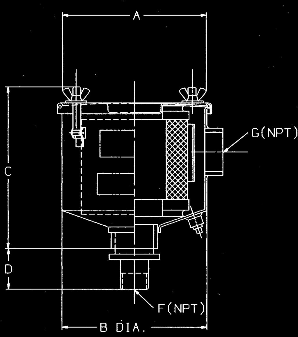
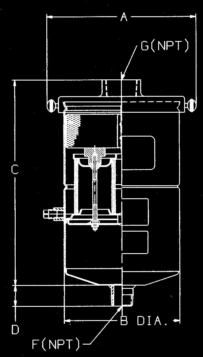
12 OME Styles Style A Style B Style B1 Style B2 Style C1 Style D Style D1 10
13 Troubleshooting When operating correctly, no smoke should be visible in the OME discharge. Oil Mist Visible Possible causes of oil mist visible in the discharge valve: The element has been removed from the casing, or an unsuitable element has been installed. Refer to 1 in Figure 3. There are gaps at the top or bottom of the element or because the element has moved or settled in transit. The seal materials have lost their resilience. Refer to 2 in Figure 3. Mist is leaking around the holddown nut and threads. A great deal of smoke can filter through a tiny gap. Refer to 3 in Figure 3. Smoke may be coming through the element because of over-tightening the holddown nut. Refer to 4 in Figure 3. The element may have ruptured because of excessive pressure drop. Refer to Elements on page 2. Oil Smoke To locate the cause(s) of oil smoke: Caution: Wear safety glasses! 1. Remove the top cover. 2. Start the pump at blank-9off. 3. Let some air into the suction port or open the gas ballast valve. 4. Look into the canister with a flashlight. Determine which problem(s) listed in the Oil Mist Visible section above applies Figure 3 5. If the leak is at the endcap: Gently turn the holddown screws a half turn at a time. If there are three nuts, rotate each a half turn at a time. Warning Overtightening may cause crushing of the element. 6. If smoke appears to be coming straight through the element, replace the element
14 Troubleshooting Table Refer to page 12 when attempting to determine the source of problems with the OME. Problem Cause Remedy Oil smoke is present in the exhaust. Smoke is coming from the relief valve. Element is not seated properly. Leaks at the holddown nuts or washers. Smoke blows straight through the element. Smoke blows straight through a new element. The canister is filled with oil. Pressure in the OME is too high. Relief valve is damaged. Remove the cover to locate cause. Refer to page 12 for determining the source. Reseat the element if possible, or replace element. Seal threads with Kinseal or RTV. Use a flat seal under washer. Replace the element. Check that the element is the correct type. Drain the oil and install a suitable drain line. Replace element. Replace the relief valve. OME fills with oil. Check valve is stuck closed. Replace the check valve. Oil smoke in the exhaust is visible in bright light. Haze accumulates indoors. A continuous high pressure operation is required. This is normal. Inadequate ventilation. Drain the oil to the gas ballast valve, or suction port. Very bright light makes dust and other extremely small particles visible. Improve the ventilation, or duct the OME exhaust outside. 12
Armstrong J Series Float, Thermostatic Steam Traps, Condensate Controllers & Liquid Drainers Installation and Maintenance Manual
 Armstrong J Series, Thermostatic Steam Traps, Condensate Controllers & Liquid Drainers Installation and Maintenance Manual This bulletin should be used by experienced personnel as a guide to the installation
Vacuum System Troubleshooting Author: Keith Webb, P.E. Application Engineering Manager
 INTRODUCTION The science of creating vacuum is often misunderstood and when the desired vacuum condition is not being achieved in a manufacturing setting this usually means production comes to a halt and
BLAST-IT-ALL BUMPER BLASTER
 LARRY HESS AND ASSOCIATES, INC 185 PIPER LANE / SALISBURY, NC 28147 PHONE: 1-800-535-2612 / FAX: 1-704-638-9311 WWW.BLAST-IT-ALL.COM BLAST-IT-ALL BUMPER BLASTER SUCTION BLAST CABINET NOTE: It is the responsibility
690 and Power Fishing Systems
 INSTRUCTION MANUAL 690 and 690-22 Power Fishing Systems Includes Serial Number AAR 3800 and higher (120 volt model) Includes Serial Number AAT 00500 and higher (220 volt model) Read and understand all
Patterson/AMT Inline Circulator Pump Refer to pump manual for General Operating and Safety Instructions.
 Please read and save this Repair Parts Manual. Read this manual and the General Operating Instructions carefully before attempting to assemble, install, operate or maintain the product described. Protect
INSTALLATION INSTRUCTIONS
 ,t_2007 Lennox Industries Inc. Dallas, Texas, USA INSTALLATION INSTRUCTIONS CH33 Series Units EVAPORATOR 505,264M (65484504) 10/07 Supersedes 09/06 COILS n _putech blications ical Litho U.S.A. RETAIN THESE
Patterson/AMT Inline Circulator Pump Refer to pump manual for General Operating and Safety Instructions.
 Please read and save this Repair Parts Manual. Read this manual and the General Operating Instructions carefully before attempting to assemble, install, operate or maintain the product described. Protect
CFH Series High Efficiency Filters
 CFH Series High Efficiency Filters Intelligent Air Technology Save energy, dollars & protect your air system The Compressed Air Challenge, a government/ industry sponsored energy savings awareness program,
MANUAL COVER. To expedite parts ordering or technical questions, please include your Model and Serial Number listed below in all correspondence.
 MANUAL COVER We at Larry Hess & Associates, Inc. would like to take this opportunity to thank you for your patronage. The machine you have purchased has been manufactured and assembled in the USA with
INSTALLATION INSTRUCTIONS
 ,1,_2008 Lennox Industries Inc, Dallas, Texas, USA INSTALLATION INSTRUCTIONS CR33 Series Coils EVAPORATOR COILS _ Technical 505,056M LL.L[ Publications 04108 Litho U.S.A. Supersedes 05/05 CR33 Series Coils...
13-1. Temperature Regulator
 -1 Step 0 Type/Structure/Features Please refer to this for type, structure and features of. Step 1 Selection Please look at the ID chart to choose the right products depending on the intended uses. Details
Safety. Rinse Kit for Multi-Pro 1200 and 1250 Turf Sprayers Model No Safety and Instructional Decals. Installation Instructions
 Rinse Kit for Multi-Pro 1200 and 1250 Turf Sprayers Model No. 106-4842 Form No. 3353-529 Rev B Installation Instructions Note: Determine the left and right sides of the machine from the normal operating
Patterson/AMT Inline Circulator Pump Refer to pump manual for General Operating and Safety Instructions.
 Please read and save this Repair Parts Manual. Read this manual and the General Operating Instructions carefully before attempting to assemble, install, operate or maintain the product described. Protect
569, 570, 571, 572 Series
 Please read and save this Repair Parts Manual. Read this manual and the General Operating Instructions carefully before attempting to assemble, install, operate or maintain the product described. Protect
Service Data Vickers. Piston Pumps. PVH98/106 Variable Displacement Piston Pump - 11 Design M-2208-S. Revised 05/01/97
 Service Data Vickers Piston Pumps PVH98/106 Variable Displacement Piston Pump - 11 Design Revised 05/01/97 M-2208-S Maximum Adjustable Stop S Option 913341 Locknut Torque 25-50 N.m. (18-37 lb. ft.) Torque
569, 570, 571, 572 Series
 Please read and save this Repair Parts Manual. Read this manual and the General Operating Instructions carefully before attempting to assemble, install, operate or maintain the product described. Protect
CONSTANT SUCTION UNIT
 CONSTANT SUCTION UNIT OPERATOR/MAINTENANCE M A N U A L Squire-Cogswell/Aeros Instruments Inc 1111 Lakeside Drive Gurnee, IL 60031-4099 1-800-662-5822/847-855-0800 Fax: 847-855-6218 www.aerosinstruments.com
Technical Data TYPE T14 & T14D TEMPERATURE PILOT SPENCE ENGINEERING COMPANY, INC. 150 COLDENHAM ROAD, WALDEN, NY SD 4511A T14 PILOT
 Technical Data SD 4511A SPENCE ENGINEERING COMPANY, INC. 150 COLDENHAM ROAD, WALDEN, NY 12586-2035 TYPE T14 & T14D TEMPERATURE PILOT PRINTED IN U.S.A. SD 4511A/9811 5 13 /16 D 4 7 /8 1 13 /16 T14 PILOT
DRYAIRE DESICCANT SYSTEM MODEL 6760
 MODEL 6760 THE SPRAY GUN PEOPLE FOR PRODUCT INFORMATION CALL: 1-800-742-7731 System Description Sharpe s DRYAIRE Desiccant Air Drying System is the painter s insurance for removing dirt, water, oil, and
690 Power Fishing System
 INSTRUCTION MANUAL 3N51 690 Power Fishing System Read and understand all of the instructions and safety information in this manual before operating or servicing this tool. Register this product at www.greenlee.com
Changing the Lucks M Series Heat Exchanger
 Changing the Lucks M Series Heat Exchanger Version 2.0 There are Four (4) main steps to removing and replacing the heat exchanger in a Lucks M Series oven. 1) If at all possible have the oven in fully
Specifications 3. Bladder 5. Chimney 12. Air Supply 12. Anti-Rollout Device and Ash Auger Tube 14. Timer 15
 TABLE OF CONTENTS Page No. Specifications 3 Bladder 5 Fire Door 7 Chimney 12 Air Supply 12 Anti-Rollout Device and Ash Auger Tube 14 Timer 15 Supply Line and Return Line Threaded Connectors 15 Low Water
Vickers. Service Data. Piston Pumps. PVH57/63 Variable Displacement Piston Pump - 11 Design M-2206-S. Revised 11/01/97
 Service Data Vickers Piston Pumps PVH57/63 Variable Displacement Piston Pump - 11 Design Revised 11/01/97 M-2206-S Maximum Adjustable Stop S Option 913341 Locknut Torque 25-50 N.m. (18-37 lb. ft.) Torque
INSTALLATION INSTRUCTIONS
 2008 Lennox Industries Inc. Dallas, Texas, USA INSTALLATION INSTRUCTIONS CH33 Series Units EVAPORATOR COILS 505,264M (65484504) 05/08 Supersedes 10/07 Litho U.S.A. RETAIN THESE INSTRUCTIONS FOR FUTURE
Service Data Vickers. Piston Pumps. PVH74/81 Variable Displacement Piston Pump - 11 Design M-2207-S. Revised 11/01/97
 Service Data Vickers Piston Pumps PVH74/81 Variable Displacement Piston Pump - 11 Design Revised 11/01/97 M-2207-S Maximum Adjustable Stop S Option 913341 Locknut Torque 25-50 N.m. (18-37 lb. ft.) Torque
Module 7: Air Supply System
 Terms and Definitions Components of the Air Supply System Basic Functions of the Air Supply System Parts of a Compressor Characteristics of Compressors Loading and Unloading Process Characteristics of
Getz Equipment Innovators 450 lb Dual Portable Dry Chemical Fill System
 Getz Equipment Innovators 450 lb Dual Portable Dry Chemical Fill System 1 Revised 11/18/10 2320 Lakecrest Drive, Pekin IL 61554 PH. (888) 747-4389 Fax (309) 495-0625 Website: www.getzequipment.com LIMITED
Oil burners fuel unit with solenoid valve
 Oil burners fuel unit with solenoid valve Type VM www.deltapumps.com VM1 - VM4U flanged Certified Quality System Printed in Italy - DE112/0404 Oil burners fuel unit with solenoid valve Type VM The DELTA
Read this entire manual before operation begins.
 Read this entire manual before operation begins. Record below the following information which is located on the serial number data plate. Serial No. Model No. Date of Installation Contents Important Information........
Operating Instructions for the BBO-1 and BBO-2 Basket Blasters
 Operating Instructions for the BBO-1 and BBO-2 Basket Blasters 2101 West Cabot Boulevard Langhorne, PA 19047-1893 www.empire-airblast.com Page 2 Model Number: Serial Number: Date of Purchase: Date of Installation:
Air Eliminator
 Cat alog Title Catalog Subtitle 730-20 Air Eliminator Principle Operation & Maintenance Manual Page 2 Table of Content Safety Warning Symbols 2 Air Elimination Principle 2 Air Eliminator Principle (Continuted)
Environmental Design The tank has separating devices at the exhaust port to prevent oil-spraying and to reduce pollution.
 As a specialized enterprise in making vacuum pumps, we have devoted ourselves to satisfy our customers need for high quality products. We adopt the latest designs and technology to make sure that our products
R 5 Central Vacuum Systems
 R 5 Central Vacuum Systems R 5 Central Vacuum Systems R 5 Rotary Vane Vacuum Pumps The modular designed Busch R 5 series rotary vane vacuum pumps are single stage, air-cooled, and direct driven. This oilrecirculating
Cased Aluminum Coils "Dedicated Upflow / Downflow" Convertible to horizontal with separately purchased kit
 18-AD32D1-3 Cased Aluminum Coils "Dedicated Upflow / Downflow" Convertible to horizontal with separately purchased kit Upflow models: 4PXCAU24BS3HAA 4PXCBU24BS3HAA 4PXCBU30BS3HAA 4PXCCU30BS3HAA 4PXCBU36BS3HAA
AIC Series Float & Thermostatic Steam Trap Installation and Maintenance Instructions
 AIC Series Float & Thermostatic Steam Trap Installation and Maintenance Instructions 138-EN Please read and save these instructions Contents General Safety Information... 3 Product Information...3-5 Product
COMPRESSED AIR DRYER. SAFETY... Page 2 MAINTENANCE... Page 5. INSTALLATION... Page 3 PARTS AND KITS... Page 6
 OWNERS MANUAL BOSS COMPRESSED AIR DRYER Distributed by Air & Vacuum Process, Inc. Phone: 281-866-9700 Fax: 281-866-9717 Email: sales@airvacuumprocess.com SAFETY... Page 2 MAINTENANCE... Page 5 INSTALLATION...
Pro-MAX Ultraviolet Sterilizer
 Pro-MAX Ultraviolet Sterilizer Lifegard Aquatics introduces the Pro-MAX UV Sterilizer, featuring a patent-pending, flow-through design with less restrictive angled inlet and outlet ports requiring less
BLAST-IT-ALL PRESSURE BLAST CABINET
 LARRY HESS AND ASSOCIATES, INC 185 PIPER LANE / SALISBURY, NC 28147 PHONE: 1-800-535-2612 / FAX: 1-704-638-9311 WWW.BLAST-IT-ALL.COM BLAST-IT-ALL PRESSURE BLAST CABINET NOTE: It is the responsibility of
Series 1140 and 1141 Temperature Regulators
 Hoffman Specialty Installation & Maintenance Instructions HS-504(E) Series 1140 and 1141 Temperature Regulators! CAUTION FOLLOW ALL INSTALLATION AND OPERATING INSTRUCTIONS. TURN OFF WATER OR STEAM BEFORE
INSTRUCTIONS FOR USE PORTABLE VACUUM SYSTEM LEI Part # s / , , , IMPORTANT INFORMATION
 INSTRUCTIONS FOR USE PORTABLE VACUUM SYSTEM LEI Part # s / 27-009, 27-010, 27-015, 27-020 IMPORTANT INFORMATION UNATHORIZED CHANGES OR ALTERATIONS TO ANY LINCOLN PORTABLE VACUUM SYSTEM WILL AUTOMATICALLY
AIR FILTER + REGULATOR + LUBRICATOR AIR FILTER. Series : V050, V100, V200, V250, V300
 AIR FILTER + REGULATOR + LUBRICATOR AIR FILTER Series : V00, V00, V00, V0, V00 AIR FILTER FEATURES: High flow Capacity Shatter- Proof polycarbonate bowl with bowl guard Minimum Pressure drop Choice of
Installation and Maintenance "L" and "LS" Series
 Installation and Maintenance "L" and "LS" Series IB-43-E This bulletin should be used by experienced personnel as a guide to the installation and maintenance of "L" and "LS" Series ultra capacity float
Model Series ELECTRIC WATER SYSTEM PUMP. PumpAgents.com - buy pumps and parts online. Model Series. Automatic Multi-Outlet FEATURES
 PumpAgents.com - Click here for Pricing/Ordering Model 36950-2 Series ELECTRIC WATER SYSTEM PUMP Automatic Multi-Outlet FEATURES Self-Priming Diaphragm Design Allows Dry Running Built-in Discharge Check
Audi-Larm Audible Alarm
 Audi-Larm Audible Alarm MAINTENANCE AND REPAIR TAL 1706 (L) Rev. 7 MSA 2017 Prnt. Spec. 10000005389(I) Mat. 10093084 Doc. 10093084 REPLACEMENT KITS AND PARTS LIST TAL 1706 (L) Rev. 7-10093084 2 Exploded
Operation Manual. Mobile Dustfree Pressure Air Blasting System HSP-20
 Operation Manual Mobile Dustfree Pressure Air Blasting System HSP-20 Clemco International GmbH Carl-Zeiss-Straße 21 Tel.: +49 (0) 8062 90080 83052 Bruckmühl Mail: info@clemco.de Germany Web: www.clemco-international.com
MEGABAND MICA INSULATED BAND HEATERS
 Injection molding machines Plastic extruders The food industry Blow-molding machines Container, pipe or tank heating The pharmaceutical industry Construction and features Economical Dependable and efficient
GASS Module. User Manual. Gas Analysis Sampling System PERMA PURE
 GASS Module Gas Analysis Sampling System User Manual PERMA PURE 8 Executive Drive Toms River, N.J. 08755 Phone: 800-337-3762 732-244-0010 Fax: 732-244-8140 e-mail: info@permapure.com Web Site: www.permapure.com
ModulAir Air Dryer with External Purge Tank - Changeover from Bendix AD-IS for Peterbilt Installation. Air Dryer Mounting Bracket (Item 1)
") Instruction Guide L31259 11/10 ModulAir Air Dryer with External Purge Tank - Changeover from Bendix AD-IS for Peterbilt Installation Air Dryer Mounting Bracket (Item 1) Tank Mounting Bracket (Item 19)
Instruction Guide L31259 11/10 ModulAir Air Dryer with External Purge Tank - Changeover from Bendix AD-IS for Peterbilt Installation Air Dryer Mounting Bracket (Item 1) Tank Mounting Bracket (Item 19)
9. Check condensate piping for sagging and/or leakage. Repair any sags or leaks before restoring power to the appliance.
 77 Do not install the condensate assembly if a component is lost or missing. Replace the entire assembly. Failure to follow this warning could result in property damage, serious personal injury, or death.
GREASE INTERCEPTORS. Z1192 GREASE RECOVERY APPLIANCE (GRA) INSTALLATION and OPERATION INSTRUCTIONS
 INSTALLATION and OPERATION INSTRUCTIONS") Z1192 GREASE RECOVERY APPLIANCE (GRA) INSTALLATION and OPERATION INSTRUCTIONS Note: Zurn Grease Interceptors with grease recognizing sensors are efficient appliances designed to separate grease from water.
Z1192 GREASE RECOVERY APPLIANCE (GRA) INSTALLATION and OPERATION INSTRUCTIONS Note: Zurn Grease Interceptors with grease recognizing sensors are efficient appliances designed to separate grease from water.
INSTALLATION INSTRUCTIONS TXV Coils for Manufactured Housing EMA
 TXV Coils for Manufactured Housing EMA NOTE: Read the entire instruction manual before starting the installation. SAFETY CONSIDERATIONS Improper installation, adjustment, alteration, service, maintenance,
PORT700CF Portable Fume Collector
 11975 Portland Ave. S. Suite 104 Burnsville, MN 55337 Phone: 952-894-6637 Fax: 952-894-0750 Email: info@ventaire.com Website: www.ventaire.com PRODUCT GUIDE FOR PORT700CF Portable Fume Collector REV:110314
Model Series Series
 PumpAgents.com - Click here for Pricing/Ordering Model 36800-Series 36900-Series ELECTRIC WATER SYSTEM PUMPS Automatic Multi-Outlet FEATURES Self-Priming Diaphragm Design Allows Dry Running Built-in Discharge
Semi-Automatic Suction Screen Filters 3"-4 Angle. Service & Maintenance Manual
 Semi-Automatic Suction Screen Filters 3"-4 Angle Service & Maintenance Manual Safety Instructions Prior to installation or handling of the filter, read the Installation and Operation instructions carefully.
LITTLE BLASTER LARRY HESS AND ASSOCIATES, INC. BLAST-IT-ALL P.O. BOX 1615 SALISBURY, NC WITH DUST COLLECTOR
 LITTLE BLASTER LARRY HESS AND ASSOCIATES, INC. BLAST-IT-ALL P.O. BOX 1615 SALISBURY, NC 28145 WWW.BLAST-IT-ALL.COM LITTLE BLASTER WITH DUST COLLECTOR MANUAL NUMBER: 561 TABLE OF CONTENTS PAGE FIGURE 1
WHAT ARE THE SPECIFICATIONS FOR THE VACUUM
 WHAT ARE THE SPECIFICATIONS FOR THE VACUUM PUMPS NEEDED TO OPERATE THE JOULE THOMSON REFRIGERATORS? INTRODUCTION TO VACUUM PUMP USAGE Joule Thomson refrigerators have a wide temperature range to operate
Installation Electric Dryers Instructions 01
 Installation Electric Dryers Instructions 01 Questions? Call 800.GE.CARES (800.432.2737) or visit our Web site at: GEAppliances.com This is the safety alert symbol. This symbol alerts you to potential
Chiltern Model Steam Engines
 Chiltern Model Steam Engines Installation and Operating Instructions Horizontal 3.5 Boiler v1.2 PLEASE CONTACT US IF YOU HAVE ANY QUESTIONS OR COMMENTS ON IMPROVEMENTS NOTE: PLEASE CLOSELY FOLLOW THE FOLLOWING
BITUMINOUS DIGITRAC AUTO STABILITY PRESS MARSHALL AUTOMATIC DIGITAL TESTER MARSHALL TESTING MACHINE W/ RECORDER MODELS
 18 BITUMINOUS DIGITRAC AUTO STABILITY PRESS The DigiTrac stability press for the Marshall method allows the operator to initially set up the platen and then the load and flow values are digitally tracked
A AD Oil burners fuel unit. deltapumps.com. DE A-AD_en_0709.pdf Page 1/1
 A AD Oil burners fuel unit deltapumps.com DE116-0709 A-AD_en_0709.pdf - 16.11.09 Page 1/1 Oil burners fuel unit Type A, AD 1- Applications The DELTA aluminium fuel unit type A is an efficient and modern
568X, 587X, 588X Series
 Please read and save this Repair Parts Manual. Read this manual and the General Operating Instructions carefully before attempting to assemble, install, operate or maintain the product described. Protect
INSTALLATION INSTRUCTIONS GEO PRIME TANK. (Patent Pending) GPC
 GPC") INSTALLATION INSTRUCTIONS GEO PRIME TANK (Patent Pending) GPC Table of Contents General Description 2 Installation 3 Flushing and Purging 5 Initial Start up 7 Adding or Checking Fluid 8 Replacing a Pump
INSTALLATION INSTRUCTIONS GEO PRIME TANK (Patent Pending) GPC Table of Contents General Description 2 Installation 3 Flushing and Purging 5 Initial Start up 7 Adding or Checking Fluid 8 Replacing a Pump
541D19 SERIES. Technical Manual. A Division of Aquion Partners L.P.
 541D19 SERIES Technical Manual A Division of Aquion Partners L.P. Table of Contents Introduction... Page 1 Technical Specifications... Page 2 Flow Diagrams... Page 3 Injector & Flow Control Selection Injector...
Powers TM Controls TH 188 Unit Mounted Thermostat
 Powers TM Controls Technical Instructions Document No. 155-064P25 TH 188-2 Description The is a remote bulb, gradual acting pneumatic instrument which maintains a pre-selected temperature by positioning
Dryer. User manual DV22K6800** DV22K A-00_EN (US)_ indd :15:41
_ indd :15:41") Dryer User manual DV22K6800** DV22K6800-03650A-00_EN (US)_151211.indd 1 2015-12-11 7:15:41 Before installation Read through the following instructions before installing the dryer, and keep this manual
Dryer User manual DV22K6800** DV22K6800-03650A-00_EN (US)_151211.indd 1 2015-12-11 7:15:41 Before installation Read through the following instructions before installing the dryer, and keep this manual
IMPORTANT INFORMATION. Revised Dishwasher Installation Instructions
 IMPORTANT INFORMATION Revised Dishwasher Installation Instructions To obtain a revised copy of the entire Dishwasher User s Manual, go to www.eurotechappliances.com. SPECIAL EDITION 11-20-02 SAVE THESE
HT650 TM FAN DRIVE SERVICE INSTRUCTIONS
 HT650 TM FAN DRIVE SERVICE INSTRUCTIONS When unpacking your product, remove all components and inspect them to ensure that no damage occurred during shipping. If any components are missing or damaged,
Oil burners fuel unit with solenoid valve
 Oil burners fuel unit with solenoid valve Type VM www.deltapumps.com VM1 - VM4U flanged Certified Quality System Printed in Germany VM_e.pdf - 18.05.08 Page 1/6 Oil burners fuel unit with solenoid valve
APPLIED VACUUM TECHNOLOGY VACUUM PUMPS & SYSTEMS
 APPLIED VACUUM TECHNOLOGY VACUUM PUMPS & SYSTEMS www.welchvacuum.com/crvpro Discover the evolution of two-stage rotary vane vacuum pumps. Built to last. Born to perform. And designed to simplify your work.
HX Field Replacement Kit
 Quantity Kit Part Number Description PE 110 Natural Gas Stainless Steel Condensate Pan PT 110 Natural Gas Polypropylene Condensate Pan Model PE 110 LP Stainless Steel Condensate Pan PT 110 LP Polypropylene
BAND HEATERS component parts
 BAND HEATERS w w w.wat tco.com OVERVIEW WATTCO band heaters are the ideal solution for high watt densities and high operating temperature applications, especially for the plastics industry. The various
OWNER S MANUAL CAVN SERIES SELF CONTAINED RETRACTABLE NOZZLE VACUUM SEALER WITH GAS PURGE
 OWNER S MANUAL CAVN SERIES SELF CONTAINED RETRACTABLE NOZZLE VACUUM SEALER WITH GAS PURGE WHAT S IN THE PACKAGE? This Operation Manual. (1) Vacuum Sealer. (1) E-(unit size) Heating Element, inside the
Elite Primer Baldor Series External Pond Pump
 Elite Primer Baldor Series External Pond Pump ( 5250PPB21, 6440PPB23, 7550PPB26, 9600PPB28) Installation and User s Guide IMPORTANT SAFETY INSTRUCTIONS, READ AND FOLLOW ALL INSTRUCTIONS. SAVE THESE INSTRUCTIONS
USER MANUAL UN-200V / UN-200VH
 USER MANUAL UN-200V / UN-200VH CONTACT US PHONE/FAX Toll Free: 800.465.1004 Phone: 801.486.1004 Fax: 801.486.1007 ADDRESS LACO Technologies, Inc. 3085 West Directors Row Salt Lake City, UT 84104 WEB www.lacotech.com
MACHINE SHOP ACCESSORIES CLEVER, TIME-SAVING PRODUCTS TO MAKE YOUR LIFE EASIER
 MACHINE SHOP ACCESSORIES CLEVER, TIME-SAVING PRODUCTS TO MAKE YOUR LIFE EASIER ROYAL R8 QUICK-CHANGE TOOLING SYSTEM Unit only protrudes 11 8" beyond spindle. 1. Loading the Quick-Change Body into a standard
SuperKlean Washdown Products
 February 2012 DURAMIX 8000 INSTALLATION AND MAINTENANCE INSTRUCTIONS **DO NOT THROW AWAY AFTER INSTALLATION** **SAVE AND DISPLAY PROMINENTLY WHERE THIS EQUIPMENT IS USED** WARNING HIGH PRESSURE AND HOT
DRY AIR SYSTEMS, INC Metro Boulevard Maryland Heights, Missouri (314) fax (314)
 fax (314)") DRY AIR SYSTEMS, INC. 2655 Metro Boulevard Maryland Heights, Missouri 63043 (314) 344-1114 fax (314) 344-0677 HD SERIES DRIERS TABLE OF CONTENTS WHY AN AIR DRYER 3 WHAT IS A DESICCANT AIR DRYER 3 Desiccant
DRY AIR SYSTEMS, INC. 2655 Metro Boulevard Maryland Heights, Missouri 63043 (314) 344-1114 fax (314) 344-0677 HD SERIES DRIERS TABLE OF CONTENTS WHY AN AIR DRYER 3 WHAT IS A DESICCANT AIR DRYER 3 Desiccant
YARWAY PROCESS THERMODYNAMIC STEAM TRAPS SERIES 40/40D AND C250/260
 SERIES 40/40D AND C250/260 Designed for a variety of high pressure and high capacity applications found in utility, industrial and marine service FEATURES Designed to fail open. Designed for superheat
INSTALLATION & OPERATING INSTRUCTIONS
 INSTALLATION & OPERATING INSTRUCTIONS WARNING RISK OF ELECTRIC SHOCK. CONNECT ONLY TO A CIRCUIT PROTECTED BY A GROUND-FAULT CIRCUIT-INTERRUPTER. THE UNIT SHOULD BE INSTALLED BY A QUALIFIED SERVICE REPRESENTATIVE.
OWNER S MANUAL CAVS SERIES SELF CONTAINED RETRACTABLE NOZZLE VACUUM SEALER
 OWNER S MANUAL CAVS SERIES SELF CONTAINED RETRACTABLE NOZZLE VACUUM SEALER WHAT S IN THE PACKAGE? This Operation Manual. (1) Vacuum Sealer. (1) E-(unit size) Heating Element, inside the manual sheet protector.
SAN RAPHAEL PRESSURE LITE VITREOUS CHINA SIPHON JET TOILET
 SAN RAPHAEL PRESSURE LITE VITREOUS CHINA SIPHON JET TOILET BEFORE YOU BEGIN HOW TO USE THESE INSTRUCTIONS Please read these instructions carefully to familiarize yourself with the required tools, materials,
A/C COMPRESSOR OIL CHECKING
 A/C COMPRESSOR OIL CHECKING 1990 Nissan 240SX 1990 AIR CONDITIONING & HEAT Compressor Oil Checking ISOLATING COMPRESSOR NOTE: Only compressors with stem-type service valves can be isolated. 1) Connect
FAN ENGINEERING. Sealing of Fan Housings
 FAN ENGINEERING Information and Recommendations for the Engineer FE-700 Sealing of Fan Housings Introduction A variety of options are offered by fan manufacturers to seal fan housings. Sealing the housing
ClearFire Economizer Model ECF Integral or External. Addendum to manuals CFH and CFV
 ClearFire Economizer Model ECF Integral or External Addendum to manuals 750-295 CFH and 750-269 CFV CB-8466 08/2011 1-GENERAL The Model ECF economizer is a stainless steel coil tube arrangement using
Owner's Manual. Please read this document carefully before installing and/or using your vacuum cleaning system.
 Owner's Manual for household use only Please read this document carefully before installing and/or using your vacuum cleaning system. Model : Serial No : Important Safety Instructions When using an electrical
SHOT BLAST CABINET USER INSTRUCTIONS. Model No: CSB20B. Part No: GC05/13
 SHOT BLAST CABINET Model No: CSB20B Part No: 7640110 USER INSTRUCTIONS GC05/13 INTRODUCTION Thank you for purchasing this CLARKE Shot Blast Cabinet which is designed for professional workshop use. Please
PUREPOWER SERIES CENTRAL VACUUM POWER UNITS PP500, PP600 & PP650
 USER GUIDE PUREPOWER SERIES CENTRAL VACUUM POWER UNITS PP500, PP600 & PP650 AB0039 FOR RESIDENTIAL USE ONLY!! MODELS SFDB-DQ, SFDB-DR AND SFDB-DS 30042509E IMPORTANT SAFETY INSTRUCTIONS SAVE THESE INSTRUCTIONS
OWNER S MANUAL AVN SERIES RETRACTABLE NOZZLE VACUUM SEALER WITH GAS PURGE
 OWNER S MANUAL AVN SERIES RETRACTABLE NOZZLE VACUUM SEALER WITH GAS PURGE WHAT S IN THE PACKAGE? This Operation Manual. (1) Vacuum Sealer. (1) E-(unit size) Heating Element, inside the manual sheet protector.
! WARNING. Replacement Head Mechanism INSTRUCTION MANUAL MM-413F
 INSTRUCTION MANUAL MM-413F Replacement Head Mechanism With Switch Assembly: 93-HD, 94-HD 93-M-HD, 94-M-HD 93-7B-HD, 94-7B-HD 93-7B-M-HD, 94-7B-M-HD Without Switch Assembly: 93-HDLS 94-HDLS Replacement
Venco 75mm (3 ) Standard and De-airing Pugmill
 Standard and De-airing Pugmill") Owner s manual for Venco 75mm (3 ) Standard and De-airing Pugmill Venco Products 29 Owen Road Kelmscott, Western Australia 6111 ph +61 8 9399-5265 fax +61 8 9 497 1335 email: venwest@iinet.net.au www.venco.com.au
Owner s manual for Venco 75mm (3 ) Standard and De-airing Pugmill Venco Products 29 Owen Road Kelmscott, Western Australia 6111 ph +61 8 9399-5265 fax +61 8 9 497 1335 email: venwest@iinet.net.au www.venco.com.au
INSTALLATION INSTRUCTIONS WALL MOUNT LINER INSERT
 Read and Save These Instructions All Hoods Must Be Installed By A Qualified Installer INSTALLATION INSTRUCTIONS WALL MOUNT LINER INSERT Read All Instructions Thoroughly Before Beginning Installation WARNING
HEATING AND AIR CONDITIONING
 XJ HEATING AND AIR CONDITIONING 24-1 HEATING AND AIR CONDITIONING TABLE OF CONTENTS page DESCRIPTION AND OPERATION SERVICE WARNINGS AND PRECAUTIONS...1 COMPRESSOR - 2.5L VM DIESEL....3 COMPRESSOR CLUTCH
Desiccant Air Drying System
 Instructions - Parts List Desiccant Air Drying System 30992L EN Model 23440 Maximum Operating Pressure 60 psi (. MPa, bar) Maximum Temperature 50 F (65 C) Model 24M78 Maximum Operating Pressure 75 psi
SECTION COMPRESSED AIR SYSTEM. A. Pipe and pipe fittings, including valves, unions and couplings.
 SECTION 15481 COMPRESSED AIR SYSTEM PART 1 - GENERAL 1.1 SECTION INCLUDES A. Pipe and pipe fittings, including valves, unions and couplings. B. Air compressor. C. After cooler. D. Refrigerated air dryer.
READ AND SAVE THESE INSTRUCTIONS
 READ AND SAVE THESE INSTRUCTIONS WARNING TO REDUCE THE RISK OF FIRE, ELECTRIC SHOCK, OR INJURY TO PERSONS, OBSERVE THE FOLLOWING: 1. Use this unit only in the manner intended by the manufacturer. If you
MEGABAND * MICA INSULATED BAND HEATERS. Construction overview Clamping mechanisms Termination styles Construction styles Watt density information
 MEGABAND * MICA INSULATED BAND HEATERS MEGABAND mica insulated band heaters are efficient and economical solutions to the heating requirements of many applications. Although their maximum sheath temperature
UltraDry s Features and Benefits
 pneuaire UltraDry s...........................................3-5 Features and Benefits..............................................................................3 How to Order....................................................................................4
NEW. APPLIED VACUUM TECHNOLOGY. ASK THE EXPERTS!
 NEW 4,6,8,16,24,30 APPLIED VACUUM TECHNOLOGY. ASK THE EXPERTS! www.welchvacuum.com/crvpro Discover the evolution of two-stage rotary vane vacuum pumps. Built to last. Born to perform. And designed to simplify
SD Bendix AD-1 and AD-2 Air Dryers
 SD-08-2403 Bendix AD-1 and AD-2 Air Dryers AD-1 AIR DRYER AD-2 AIR DRYER FIGURE 1 The air dryer collects and removes moisture and contaminants before the air reaches the first reservoir. It is distinctly
NEW. APPLIED VACUUM TECHNOLOGY. ASK THE EXPERTS!
 NEW APPLIED VACUUM TECHNOLOGY. ASK THE EXPERTS! www.welchvacuum.com/crvpro Discover the evolution of two-stage rotary vane vacuum pumps. Built to last. Born to perform. And designed to simplify your work.