OIL FIRED BOILERS FIREBIRD S RANGE COMMISSIONING USER INSTRUCTIONS THIS MANUAL MUST REMAIN WITH THE HOUSEHOLDER ON COMPLETION OF INSTALLATION
|
|
|
- Miranda Miles
- 6 years ago
- Views:
Transcription

1 OIL FIRED BOILERS P O P U L A R H E A T - P A C I N S T A L L A T I O N COMMISSIONING S E R V I C I N G & USER INSTRUCTIONS THIS MANUAL MUST REMAIN WITH THE HOUSEHOLDER ON COMPLETION OF INSTALLATION

2 A Formula For Better Boiler Service HOUSEHOLDER Switch on your central heating boiler and check its operation before commencement of heating season. During the summer season your boiler may be switched off for long periods. In our climate, summer dampness attacks electrical circuits, burner and boiler parts. Deposits on boiler and flue surfaces dampen, and may fall loose resulting in flues and ducts becoming clogged. Deposits also act as an insulator and thus reduce efficiency. Boilers and burners should be cleaned and serviced before summer switch-off, then switched on and checked again before needed for the winter heating. This eases seasonal rush on your service engineer and helps him/her give you a better service. Arranging a regular service contract with him/her will help keep your boiler in top condition. A stitch in time saves nine - and disappointment. Issued by FIREBIRD BOILERS in the interest of our customers and the heating industry.
3 CONTENTS FOREWORD P INTRODUCTION P STANDARDS & REGULATIONS P SAFETY P. 5 Health & Safety Fuel Spillage Safety First Aid 4. OPERATING INSTRUCTIONS P.6-7 a. Boiler controls b. Operating procedure c. Burner lockout / resetting 5. BOILER TECHNICAL SPECIFICATIONS P Boiler Diagrams, Dimensions & Specifications 6. BURNER TECHNICAL SPECIFICATIONS P Oil Burner Outputs Specification Riello oil burner specification & technical details 7. WIRING SPECIFICATIONS P. 16 Thermostat Control & Wiring 8. INSTALLATION P Positioning Boiler Flue Systems Boiler siting Regulations & Standards Ventilation and Combustion Air 1. Conventional Flue 2. Balanced Flue Domestic Htg. & H.W. Systems, Electrical Supply 9. FLUE SYSTEMS P Important notice Important Balanced flue systems Concentric flue systems High Level Balanced Flue systems Flue installation instructions 10. OIL SUPPLY P Oil storage tank siting Flexible oil pipe(s) Single pipe system Two pipe systems Tigerloop single pipe systems Regulations & Standards 11. COMMISSIONING P. 30 Procedures Handing over 12. SERVICING P. 31 Recommended service intervals The oil tank The boiler The Burner 13. FAULT FINDING BURNER P SPARE PARTS P Burner P. 33 Popular/Boilerhouse P. 34 Kitchen P. 35 Heat Pac S P. 36 Heat Pac S Turret P. 37 Heat Pac Slimline P. 38 Control Unit P. 39 View Glass P. 40 Baffles P REPORTS & RECORDS P Service Record P. 42 Commissioning Record P. 43 Notes P. 44 Attention Installer P. 44 Guarantee Card P. 45 1
4 INSTALLATION & COMMISSIONING: Boilers must be installed, commissioned and serviced by qualified and experienced persons and as set out in the Installation Manual, using correct test equipment. EXPANSION VESSEL: Total water content of system and boiler must be calculated to determine the correct size of pressure vessel. WARNING: The manufacturer cannot accept responsibility for any damage to persons, animals or property due to error in installation or in the burner adjustment or due to improper or unreasonable use or non observance of the technical instruction enclosed with the burner, or due to the intervention of unqualified personnel. GUARANTEE: All Firebird oil Boilers have a 2 year comprehensive warranty which extends to 5 year on the boiler shell. The Guarantee card must be fully completed and returned to Firebird within 28 day s of complete installation & commissioning. Consumable components, the nozzles and the oil hose are excluded. The terms laid down on the Guarantee must be adhered to. 2
5 FOREWORD We would like to thank you for purchasing a high efficiency Firebird domestic central heating oil fired boiler. This instruction manual is produced for the reference and guidance of qualified installation engineers such as those who are OFTEC registered. EU legislation governs the manufacture, operation and efficiency of all domestic central heating oil boilers. Our boilers and burners will are supplied as matched units tested and approved to OFTEC Standard OFS Al00. FIREBIRD Boilers are full manufacturing members of OFTEC (Oil Firing Technical Association) and are participating in its Boiler testing and approvals programme to comply with OFS A100 and EC Efficiency Directive. Boilers must be installed, commissioned and serviced by qualified and experienced engineers (OFTEC approved/competence certified required in UK.) It is the responsibility of the Installer/Householder to ensure that the boiler is properly commissioned. Failure to do so may invalidate the boiler Guarantee and extended warranty. All appropriate OFTEC manuals and BS Standards should be studied and their requirements adhered to and used in conjunction with these instructions. This manual includes a list of some BS Standards and Building Regulations. OFTEC is conducting training and registration of engineers and this is to be commended, as reading of this manual alone for installation and servicing procedures cannot replace the critical advantage provided by training and years of experience. 1 INTRODUCTION The Firebird range of Oil Boilers includes the Firebird S Range, Kitchen Model, Room Sealed and Boilerhouse models. The range is further extended with the Popular Conventional flue Boilerhouse models, Heat Pac Outdoor models. All units give clean combustion while Kitchen-quiet operation is a feature of balanced flue indoor models. The entire range is complemented by a highly efficient matching pressure jet burner which produces very low NO x emissions. A drain-off cock is fitted inside the boiler beside the burner and there are flow and return connections provided under top lid of the boiler for connection to the heating and hot water systems. As all servicing can be carried out from the front, the boiler many be fitted under a kitchen worktop. The burner is factory set for use with C2 kerosene to BS 2869:1998. However, Class D fuel to BS 2869:1998 (gas oil) may only be used on a conventional flue installation, a oil pre-heater may be necessary. 3
6 2 STANDARDS & REGULATIONS To ensure the highest standards of installation & safety, it is important that the boiler be installed in compliance with the following regulations where applicable. All CURRENT editions of the appropriate Building Regulations:- Part L & J Part F Part L Part J BS 5410 BS 799 BS BSEN 12828:2003 BS 7074 BS BS BS BS BS 4543 part BS BS England & Wales Section III Scotland - Conservation of Fuel Power Northern Ireland - Conservation of Fuel Power Republic of Ireland - Conservation of Fuel Power Part Code of practice for Oil Firing Installations. Part Specification for Oil Storage Tanks. Performance requirements for oil burning appliances. (UK National Annex). Heating Systems in Buildings - Designed for water based heating systems Part Application, selection and installation of expansion vessels and ancillary equipment for sealed water systems. Installation of hot water supplies for domestic purposes. Code of Practice for treatment of water in heating systems. Metal flue pipes, fittings, terminals and accessories. Clay flue linings and flue terminals. Factory made insulated chimneys for oil fired appliances. Design, installation, testing and maintenance of Services supplying water. Current lee Regulations. Local Water Undertaking Bylaws. Water supply (water fittings) Regulations The Control of Pollution (Oil) Regulations. In addition, the work must comply with OFTEC Installation Requirements for oil fired boilers and oil storage tanks. The installer should also be aware of his/her responsibilities under The Health and Safety at Work Act. The interests of safety are best served if the boiler is installed and commissioned by a competent engineer, OFTEC trained and Registered. If not a Building Notice is required in England & Wales. Other parts of the British Isles including the Channel Islands also require notification to building Control. It is the responsibility of installer and everyone concerned with any aspect of installation to ensure that all applicable standards and regulations are fully adhered to. OFTEC also publish excellent guides including: Safe Working Practices for Oil Firing Technicians' - OFTEC Technical Book Three (Installation requirements for Oil Fired Boilers and Oil Storage Tanks) - OFTEC Technical Book Four (Domestic Heating Systems) and it is recommended that these should adhered to Domestic Heating Design Guide. COPIES OF BRITISH STANDARDS MAY BE PURCHASED DIRECT FROM: BSI (Customer Services), 389 Chiswick High Rd., London W4 4AL. Tel.: Fax: International and EC Standards are also available from above. OFTEC PUBLICATIONS ARE AVAILABLE FROM:- OFTEC, Oil Firing Technical Association, Foxwood House, Dobbs Lane, Kesgrave, Ipswich. IP5 2QQ BOILER INSTALLATION: BS 5410 : Part gives the requirements for domestic boiler and oil storage installations. For boilers installation with regard to cleaning and flushing and providing inhibitors as are followed for any other boiler. Manufacturers instructions must always be followed together with the requirements of BSEN 12828, 2003 & BS EN 12831, 2003, which supersede BS , and the statutory requirements of the Building Regulations. 4
7 3 SAFETY HEALTH & SAFETY INFORMATION Under the Consumer Protection Act 1987 and Section 6 of the Health and Safety Act 1974, we are required to provide information on substances hazardous to health. INSULATION AND SEALS Ceramic Fibre, Alumino - Silicone Fibre material are used for boards, ropes and gaskets. Known hazards are that people may suffer reddening and itching of the skin. Fibre entering the eye will cause foreign body irritation. It may also cause irritation to the respiratory tract. Precautions should be taken by people with a history of skin complaints or who may be particularly susceptible to irritation. High dust levels are only likely to arise following harsh abrasion. Suitable personal protective equipment should be worn where appropriate. Generally, normal handling and use will not give discomfort. Follow good hygiene practices, wash hands before consuming food, drink or using the toilet. First Aid - Medical attention should be sought following eye contact or prolonged reddening of the skin. The small quantities of adhesives and sealants used in the product are cured. They present no known hazards when used in the manner for which they are intended. THIS PRODUCT HAS BEEN DESIGNED TO THE FOLLOWING STANDARDS: EMC Directive (Electromagnetic compatibility) 89/336/EC Standards: EN : Electromagnetic Compatibility Generic Standard - Immunity for residential, commercial and light industrial environments. (Feb.2001) EN : Electromagnetic Compatibility Generic Standard - Emission standard for residential, commercial and light industrial environments. (Feb.2001) LV Directive (Low voltage) 73/23/EEC Standard: IEC : Household and similar electrical appliances - Safety (May 2001) Boiler Efficiency Directive 92/42/EEC Standard: BSEN 304: Oil boilers with forced draft burners. FUEL SPILLAGE 1. Switch off all electrical and other ignition sources. 2. Remove all contaminated clothing to safeguard against fire risk and skin damage. Wash affected skin thoroughly with soap and water and remove clothing to a safe well ventilated area and allow to air before cleaning. 3. Contain and smother the spill using sand or other suitable oil absorbent media or non-combustible material. 4. Do not allow fuel to escape into drains or water courses. If this happens, contact the relevant authorities in your area. (Ireland Only) Contact The Environment Agency on (UK Only) 5. Consult local Authority about disposal of contaminated soil. SAFETY Safe use of Kerosene and Gas Oil. These fuels give off a flammable vapour when heated moderately. Vapour ignites easily, burns intensely and may cause explosion. The vapour can follow along at ground level for considerable distances from open containers and spillages collecting as an explosive mixture in drains, cellars, etc. Fuels remove natural oils and fats from the skin and this may cause irritation and cracking of skin. Barrier cream containing lanolin is highly recommended together with good personal hygiene and where necessary appropriate personal protection equipment. (P.P.E.) Gas oil may also cause irreversible damage to health on prolonged or repeated skin contact. Always store fuels in a properly constructed and labelled tank. Always handle fuel in open air or well ventilated space away from sources of ignition and refrain from smoking. Always drain fuel using a proper fuel retriever, funnel or mechanical siphon. Never apply heat to a fuel tank, container or pipework. Never siphon fuel through tube by mouth. If accidentally swallowed contact doctor immediately and do NOT induce vomiting. Avoid inhaling fuel vapour as this can cause light headedness and seriously impair judgement. FIRST AID If fuel is accidentally swallowed:- * Seek medical attention immediately. Do NOT induce vomiting. If fuel is splashed into eyes:- * Wash out with running water for at least ten minutes and seek medical attention. 5
 OPERATING PROCEDURE (All models) TO START THE BOILER FOLLOW THIS SEQUENCE: Turn on fuel supply.")
.")


8 4 OPERATING INSTRUCTIONS (a) BOILER CONTROLS High limit stat activated (amber) Mains on (green) figure A. (b) OPERATING PROCEDURE (All models) TO START THE BOILER FOLLOW THIS SEQUENCE: Turn on fuel supply. Switch power supply to boiler ON. For Model S remove front cover. Activate the mains on switch. Set the boiler thermostat to the required temperature (figure B). The boiler thermostat controls the boiler operation by automatically maintaining the required boiler water temperature output. Safe operation is also maintained by the burner control system which provides the required ignition and shut off sequence. If the optional timer control is fitted this will automatically switch the boiler off and on when heat is required. THE BOILER CAN BE TURNED OFF BY ANY OF THE FOLLOWING MEANS: Turn the timer control (if fitted) to OFF. Turn the boiler thermostat to OFF. Turn the mains ON switch to OFF. Turn OFF the mains electrical supply to the boiler. WHEN SERVICING ALWAYS SWITCH OFF THE MAINS SUPPLY TO THE BOILER. figure B. Dual Thermostat Mains Plug Burner Plug 6

9 4 OPERATING INSTRUCTIONS (c) BURNER LOCKOUT To reset when Lock-out light shows: Press glowing reset button on burner control box. Reset Button Inside Burner Box The boiler is factory fitted with a burner control box lockout safety feature which operates automatically if a fault occurs in the burners operation. Should this occur, the light on the front of the burner - See above - will illuminate and its cause must be investigated. This could be caused by: A. An interruption in the fuel supply. (Eg. empty oil supply tank) B. An electrical supply fault. C. A fault with the burner or its safety control system. D. The failure of a component. (Eg. photo cell) E. Worn or dirty oil nozzle. Before attempting to restart the boiler the front panel and the burner cover should be removed and a visual check made for any obvious problems such as oil leaks, loose connections etc. ENSURE OIL TANK CONTAINS CORRECT GRADE FUEL. TO RESTART THE BOILER 1. Press reset button (see diagram above) 2. Ensure that the boiler thermostat, time switch (if fitted) and any external controls connected to the boiler are set to call for heat. 3. Check that the oil supply valves are open and that there is sufficient oil in the tank. 4. Check that the burner lockout light is unlit and with the mains ON the boiler will be ready to commence its start sequence. HOW TO BLEED AN OIL PUMP See Page 15 - Burner Specifications. Ref: Priming Pump. SERVICING The boiler requires servicing on an annual basis to ensure it maintains its efficiency, continues to perform reliably and as a regular check on its built-in safety features. It is important that servicing should be conducted by a competent engineer, preferably one who is OFTEC trained and registered. 7
10 5 BOILER TECHNICAL SPECIFICATION Firebird S. Kitchen Model Diagrams Firebird S. Kitchen Model 50-70/ H. 845mm B. 190mm H. 845mm B. 220mm H. 1050mm B. 221mm H. 1055mm B. 232mm W. 380mm C. 140mm W. 440mm C. 140mm W. 442mm C. 175mm W. 462mm C. 165mm D. 595mm E. 85mm D. 595mm E. 85mm D. 705mm E. 95mm D. 790mm E. 95mm A. 745mm F. 60mm A. 745mm F. 60mm A. 925mm F. 115mm A. 925mm F. 115mm G. 590mm G. 590mm G. 640mm G. 640mm Firebird S. Kitchen Model H. 960mm C. 190mm H. 1015mm C. 190mm W. 510mm E. 95mm W. 580mm E. 65mm D. 820mm F. 115mm D. 945mm F. 135mm A. 885mm G. 675mm A. 930mm G. 700mm B. 90mm I. 1115mm B. 90mm I. 1165mm 8
11 5 BOILER TECHNICAL SPECIFICATION Firebird S. Boiler House Dimensions Firebird S. Boiler House Model CONVENTIONAL. ROOM SEALED (SNORKEL) Building Reg. & BS Require a base tray for this design of unit. MODEL H W D A B C E F G H2 50/ / / / / / / C Firebird S. Boiler Specifications OUTPUT RANGE PRESSURE JET OIL BURNER RIELLO - SEE SECTION 2D BURNER SETTINGS (ECOFLAM & BENTONE STERLING OPTIONS AVAILABLE) FLOW & RETURN CONNECTIONS 4x1 BSP 4x1 BSP 4x1 BSP 4x1 1 /2 BSP 4x1 1 /2 BSP 4x2 BSP 4x2 BSP DRAIN OFF CONNECTION 1 /2 BSP SOCKET & PLUG FITTED ON ALL MODELS FLUE OPTIONS A. CONVENTIONAL FLUE B. BALANCED FLUE 5 O.D. 5 O.D. 5 O.D. 6 O.D. 6 O.D. 8 O.D. 8 O.D. CONVENTIONAL FLUE DRAUGHT MINIMUM: 0.04 INCHES WATER GAUGE. MAXIMUM 0.15 INCHES W.G. MAXIMUM OPERATING PRESSURE 3 BAR 3 BAR 3 BAR 3 BAR 3 BAR 3 BAR 3 BAR TEST PRESSURE 4.5 BAR WEIGHT in Kg BOILER. BOILERHOUSE BURNER WHITE CASED BOILER & BURNER WATER CONTENT IN LITRES TEMPERATURE CONTROL CONTROL THERMOSTAT: ADJUSTABLE BETWEEN 60 C - 80 C. LIMIT THERMOSTAT: MANUAL RESET LIMIT THERMOSTAT FACTORY SET AT 110 C. ELECTRICAL SUPPLY 230v. AC 50Hz 5 AMP FUSE FUEL USE C2 KEROSENE IN BALANCED FLUE INSTALLATIONS ONLY. Class D GAS OIL (CF Option). 9
12 5 BOILER TECHNICAL SPECIFICATION Turret Flue Heat Pac Diagrams & Specifications SLIMLINE HEAT PAC H. E. H. E. A. B. B. A. C. C. D. W. Removable lid to access plumbing connections Heat Pac Outline Dimensions Plumbing Access Point Dimensions MODEL D W H A B C E / D. W. HEAT PAC Heat Pac Outline Dimensions Plumbing Access Point Dimensions MODEL D W H X A B C E F G 70/ / / / / / HEAT PAC S (Northern Ireland Only) Heat Pac-S Outline Dimensions Plumbing Access Point Dimensions MODEL D W H Y A B C E F J 70/90 S /120 S /150 S
13 5 BOILER TECHNICAL SPECIFICATION BOILER THERMOSTATS - FUNCTION The CONTROL THERMOSTAT [1] on the boiler allows the householder to vary the water flow temperature from a low of 60 C to a high of 80 C to 82 C, depending on the model. In accordance with EU boiler standards, your boiler is also fitted with a SAFETY HIGH LIMIT THERMOSTAT [2], fixed at 114 C. This system protects the boiler in the event of the control thermostat failing and keeps the boiler safe. The safety high limit thermostat [2] will shut off the boiler and will require the limit button to be pushed to restart the boiler. If the problem re-occurs, you should call your service engineer. In cases where the flow from the boiler is down to the heating system, fitting a PUMP OVER RUN THERMOSTAT [3] (A Pipe Stat) is recommended. This is to prevent the residual heat build up in the boiler from unnecessarily activating the high limit thermostat and thus causing nuisance. See Heat Pac Wiring Diagram in Installation Instructions on page 16. PLASTIC PIPING - WARNING The boiler thermostat control and safety system is not designed, and must not be relied on, to protect plastic pipe from overheating. Plastic pipe must never be connected directly to the boiler. If you choose to use plastic pipe anywhere on your hot water circuits, then please consult the plastic pipe manufacturer for their instructions on how to ensure their product never overheats. Our boiler control and safety high limit thermostats are not designed to fulfil this function. (They may suggest the fitting of independent pipe thermostats, or thermostatic mixing valves linking flow and return). Firebird accepts no responsibility for failure of plastic piping and fittings for what ever reason. TIME AND TEMPERATURE CONTROLS The Building Regulations state that central heating systems must have time and temperature control on the pipe circuits (eg Thermostatic Radiator Valves / TRVs, Room thermostats, cylinder thermostats etc.) on both fully pumped and semi-gravity systems. 11
14 6 BURNER TECHNICAL SPECIFICATION BURNER SETTINGS FOR FIREBIRD BOILER RANGE (KEROSENE) Variations in nozzle throughput, flue type & draught, oil viscosity etc. may give results differing from these laboratory performance figures. RIELLO RDB BURNER SETTINGS Range Burner Head Fuel Nozzle P.P. Air Air Co2 Fg. Smoke Type Box No. 50,000 Riello RDB 2.2 T1 K.4 80 H 10 Bar ,000 Riello RDB 2.2 T1 K.5 80 H 8.5 Bar ,000 Riello RDB 2.2 T3 K.6 80 H 8 Bar ,000 Riello RDB 2.2 T3 K H 8 Bar ,000 Riello RDB 2.2 T3 K S 9.5 Bar ,000 Riello RDB 2.2 LD3 K S 9.5 Bar ,000 Riello RDB 2.2 LD3 K S 9 Bar ,000 Riello RDB 2.2 LD3 K S 8 Bar ,000 Riello RDB 2.2 T5 K S 9 Bar ,000 Riello RDB 2.2 T5 K S 7 Bar ,000 Riello RDB 2.2 T5 K S 8.5 Bar ,000 Riello RDB 4. Comb. K S 8.5 Bar ,000 Riello RDB 4. Comb. K S 8.2 Bar ,000 Riello RDB 4. Comb. K S 8 Bar ,000 Riello RDB 4. Comb. K S 8 Bar ,000 Riello RDB 4. Comb. K S 7.1 Bar ,000 Riello RDB 4. Comb. K S 8 Bar ,000 Riello RDB 4. Comb. K S 8 Bar ,000 Riello RDB 4. Comb. K S 8 Bar ,000 Riello RDB 4. Comb. K S 9.2 Bar MAX BURNER SETTINGS Range Burner Head Fuel Nozzle P.P. Air Air Co2 Fg. Smoke Type Box No. 50,000 Max 4 K.5 80 H 7Bar ,000 Max 4 K.5 80 H 10Bar ,000 Max 4 K.6 80 H 8Bar ,000 Max 4 K.6 80 H 9.5 Bar ,000 Max 4 K S 8 Bar ,000 Max 4 K S 8 Bar ,000 Max 4 K S 8 bar ,000 Max 4 K S 10 Bar ,000 Max 4 K S 9 Bar ,000 Max 4 K S 7 Bar ,000 Max 4 K S 8 Bar ECOFLAM MAX BURNER BLAST TUBE SPECIFICATION APPLIANCE MODEL FLAME TUBE FLAME TUBE O/A LENGTH FIREBIRD 70 / VAIN 5MM SLOTS BFB / MM FIREBIRD 90 / VAIN 10MM SLOTS 5MM HOLES BFB / MM FIREBIRD 120 / 150 BFB01104/002 DIFFUSER: BFD01014/ MM The above performance figures are based on ideal laboratory test conditions. Air shutter settings above may need to be revised to take into consideration difference in resistances between conventional and balanced flue installations. Use flue gas analyser to achieve optimum results. 12


15 6 BURNER TECHNICAL SPECIFICATION 13
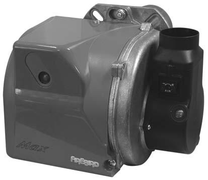
16 6 BURNER TECHNICAL SPECIFICATION 1. BURNER DESCRIPTION One stage kerosene burner. The intake air temperature must not be over 70. Burner with CE marking in conformity with EEC directives: EMC 89/336/EEC and Efficiency 92/42/EEC. CE Certification No.: /01 as 92/42/EEC. 3 9 Fig Pump 2 - Control box Reset button with lock-out lamp 4 - Flange with insulating gasket 5 - Air damper adjustment screw Snorkel (BF) 7 - Pump pressure adjustment screw Pressure gauge port Photoresistance D BURNER EQUIPMENT Flange with insulating gasket No. 1 Screws for flange to be fixed to boiler No. 4 Screw and nuts for flange No. 1 Flexible oil pipes with nipples No. 2 Hexagonal key No. 1 Screw of by-pass pump No. 1 Plastic air cover No. 1 ELECTRODE SETTING Riello RDB 2.2 ATTENTION Before assembling or removing the nozzle loosen screw (A) and move electrodes forward. 14
17 6 BURNER TECHNICAL SPECIFICATION HYDRAULIC SYSTEM WARNING Riello Burner Specification The pump is designed to allow working with one pipe. In order to obtain two pipe working it is necessary to unscrew the return plug (2), screw in the by-pass screw (3) and then screw in return oil line (2). (See fig. 4). In the two pipes systems, before starting the burner make sure that the return pipe-line is not clogged. An excessive back pressure would cause the damage of the pump seal. Fig D5741 min. 0.1 m H max. 4 m F ig. 5 H meters I. D. 8 mm L meters I. D. 10 mm PRIMING PUMP: On the system in fig. 5 it is sufficient to loosen the suction gauge connection (6, fig. 4) and wait until oil flows out. On the systems in fig. 6 and 7 start the burner and wait for the priming. Should lock-out occur prior to the arrival of the fuel, await at least 20 seconds before repeating the operation. The pump suction should not exceed a maximum of 0,4 bar (30 cm Hg). Beyond this limit gas is released from the oil. Oil pipes must be completely tight. In the vacuum systems (fig. 7) the return line should terminate within the oil tank at the same level as the suction line. In this case a non-return valve is not required. Should however the return line arrive over the fuel level, a non-return valve is required. This solution however is less safe than previous one, due to the possibility of leakage of the valve. 8 1 H meters I. D. 8 mm D Suction pipe 2 - Return line 3 - By-pass screw 4 - Pressure gauge connection & Bleed screw 5 - Pressure adjuster 6 - Vacuum gauge connection 7 - Valve 8 - Auxiliary pressure test point L meters I. D. 10 mm H D1842 max. 4 m H Fig. 6 F ig. 7 D5740 H max. 4 m H Check periodically the flexible pipes conditions. It is necessary to install a filter on the fuel supply line. H = difference of level L = Max. lenght of the suction line I.D. = Interminal diameter of the oil pipes. For Full details on suction line systems please refer to OFTEC Technical Information Sheet T1/139 (T32) 15
18 7 WIRING ELECTRICAL SUPPLY The boiler and controls require 230V 1 phase 50Hz electric supply protected with a 5amp fuse. THIS APPLIANCE MUST BE EARTHED. A qualified electrician must carry out all electric wiring in accordance with current I.E.E Regulations and any local regulations which may apply. The mains electrical supply must be taken from a double pole isolating switch with a 5amp fuse, positioned somewhere close to the boiler. Heat resisting cable must be used which can be routed into the boiler through the access provided on either side of the base. Ancillary controls may be provided for with terminal connections in the control panel. Firebird Kitchen C, System C & Heat Pac C' Wiring Diagram To Dual Temperature Control Thermostat And Safety High Limit Thermostat Safety Limit Thermostat. C E 2 Insert Link A. C Control Thermostat. E 2 1 Safety Limit Thermostat. Temperature Control Dial Reset Pin Inside Screw Off Cover Mains Plug. C E L N Burner Lockout. Mains In Here. To Burner MAINS IN Protect Supply With 5 Amp TIME-SWITCH Pressure Switch Circuit closes on drop of system pressure. (.2bar) L. E. PRESSURE SWITCH N. L2. 4 Pin Isolating Plug FROST THERMOSTAT Over Heat Thermostat Set at 93 C CONTROL STAT. & LIMIT STAT. Normally Closed Contacts Open On Rising Temp. N. Common Normally Open Contacts Close On Rising Temp. HEATING UNIT PUMP PUMP OVER HEAT THERMOSTAT NOT IN KITCHEN MODELS 12 Pump Overheat Thermostat C L E N 1.Lamp Neutral. 2.Mains On Lamp. 3.Lock out Lamp. 4.Permanent Live Frost Stat. 5.Neutral For Frost Stat. 6.Earth For Frost Stat. 7.-Live From Frost Stat. Fitted only on Kitchen C Boilers Fitted On Heat Pac's to GB Only 8.-Power Supply For Pump From Common On Over Heat To Pressure Switch To Dual Stat. And Burner Switch Live To Poll 1 On Over Heat Stat. L2.- Permanent Live To Poll 2 On Over Heat Stat. 24.-Return From Pressure Switch. L2 L2.- Permanent Live. L.- Switched Live. N.- Neutral. E - Earth. L2 N E L1 (L2) N E L Mains Plug. Circulating Pump Pressure 16
19 8 INSTALLATION POSITIONING BOILER Ensure that adequate clearance is available for making the water and flue connections. As the boiler is serviced from the front, no headroom clearance is necessary but a clearance of 750mm must be available at the front of the boiler. No special hearth is required as the boiler is fully insulated, but the floor must be level and capable of supporting the weight of the boiler and its water content. Sound levels must also be a consideration. Whilst the Firebird is one of the quietest boilers on the market, some householders are particularly sensitive and the following points should be considered: 1. Tiled surfaces in a small room will amplify noise - particularly if the wall construction is hollow. 2. If a conventional flue passes through a bedroom it is capable of transmitting noise. 3. Low level balanced flue terminals can produce exhaust noise on the outside terminal and this should be considered when siting near adjacent property. 4. The Firebird Balanced Flue Kit has been specifically designed for Firebird s indoor boilers. The use of third party low level flue kits is not recommended and will affect its warranty. 5. The Siting of the boiler should take into account the disposal of condensate products. It is recommended that a suitable corrosion inhibitor is added to the heating system. Dilution of the inhibitor due to the system being constantly topped up via mains supply will invalidate warrantee on boiler shell Existing systems should be treated with chemical cleaner and properly flushed before the boiler is fitted and corrosion inhibitor added. FLUE SYSTEMS IMPORTANT Because of the improved efficiencies of boilers under E.U. Efficiency requirements and OFS A100 Standard, it is necessary to pay extra special attention to flues and chimneys. The improved efficiency figures achieved by modern oil boilers are attained by using more of the heat (higher temperatures) heretofore allowed into flues and chimneys. This previously wasted heat helped to keep bad and poorly operating and often uninsulated flues and chimneys from condensing and causing problems. Please be fully aware of this when replacing an existing boiler. An old and poorly operating flue may need to be replaced to take full advantage of improved efficiencies and to avoid flue gases condensing and appearing as white water vapour (pluming) at flue (chimney) outlet. New flues and chimneys should be properly insulated and constructed to prevent condensation and draughting problems. Every individual concerned with any aspect of installation should be aware of the foregoing and should have full knowledge of and work to European, National and Local Govt. Standards and Building and Installation Regulations. These manufactures instructions must not in any way be mis-interpreted as over-riding the above or any statutory regulations. It is absolutely essential that the boiler is properly installed so that NO FLUE GASES can enter the building at any time. Flue pipes should be safely sealed into the wall to prevent flue gases re-entering room or building. Refer also to page 20. NOTE: All brick chimney constructions must comply with current building regulations and BS 5410: Part 1. Insulated factory made chimneys should comply with BS * DRAUGHT READINGS ARE SHOWN ON PAGE 9 CONVENTIONAL BRICK CHIMNEY WITH LINER 17

20 8 INSTALLATION BALANCED FLUE SITING A. Horizontal from opening, airbrick, opening window etc. B. From an internal or external corner. C. Below an opening, airbrick, opening window etc. Book three Aug See note at foot of page Notes: 1. The terminal should be positioned to avoid combustion products entering the building or accumulating in stagnant pockets around buildings. 2. The terminal must be protected by a guard if it is less than 2 metres above ground level or in a position where any person has access to it (i.e. a balcony). 3. A heat protection shield should be fitted if the terminal is less than 850mm from a plastic or painted gutter or less than 450mm from painted eaves. Building Regulations BUILDING REGULATIONS A B C Northern Ireland Republic of Ireland *Where the terminal is within 1 metre of any plastic material, such material should be protected from the effects of combustion products of fuel. There are additional general requirements in most Regulations and Standards that the flue must be positioned so that it does not cause a nuisance and permits the dispersal of combustion products. NOTE: The Buildings Regulations clearances shown above are minimum allowed. To take account of prevailing site conditions it is advisable wherever necessary to follow the manufacturers preferred recommendation. If in doubt contact manufacturer for advice. ALWAYS CHECK FOR ANY BUILDING REGULATIONS AMENDMENTS WHICH MAY HAVE BEEN ISSUED AFTER THE PUBLICATION OF THIS MANUAL 18

21 8 INSTALLATION Clearances advised by the BRITISH STANDARDS for Open Flues, Low Level Balanced Flues and Balanced Flues fitted to Oil Fired Boilers. THESE ARE ALSO THE BUILDING REGULATIONS FOR ENGLAND, WALES & SCOTLAND Minimum distances to terminals in millimetres as measured from top of the chimney or the rim of a low level discharge opening. APPLIANCE BURNER TYPE PRESSURE JET VAPOURISING A Directly below an opening, air brick, opening window etc * 600 Not allowed B Horizontally to an opening, air brick, opening window etc * 600 Not allowed C Below a gutter, eaves or balcony with protection * 75 Not allowed D Below a gutter or a balcony without protection 600 Not allowed E From vertical sanitary pipework 300 Not allowed F From an internal or external corner or surface or boundary alongside the terminal 300 Not allowed G Above ground or balcony level 300 Not allowed H From a surface or boundary facing the terminal 600 Not allowed J From a terminal facing the terminal 1200 Not allowed K Vertically from a terminal on the same wall 1500 Not allowed L Horizontally from a terminal on the same wall 750 Not allowed M Above the highest point of an intersection with the roof N From a vertical structure on the side of the terminal Above a vertical structure less than 750mm from the side of the terminal P From a ridge terminal to a vertical structure on the roof 1500 Not allowed These notes form an integral part of the information shown above. 1. Terminals should be positioned so as to avoid products of combustion accumulating in stagnant pockets around the building or entering into buildings. 2. Appliances burning Class D oil have additional restrictions.(see in Oftec Book 3 - Aug. 2002) 3 Vertical structure in N, 0 and P include tank or lift rooms, parapets, dormers etc. 4. Terminating positions A to L are only permitted for appliances that have been approved for low level flue discharge when tested to OFS A100 or A Terminating positions must be at least 1.8 metres distant from an oil storage tank unless a wall with at least 30 mins fire resistance and extending 300mm higher and wider than the tank is provided between the tank and the terminating position. 6. Where a flue is terminated less than 600mm away from a projection above it and the projection consists of plastic or has a combustible or painted surface, then a heat shield of at least 750mm wide should be fitted to protect these surfaces. 7. For terminals used with vapourising burners, a horizontal distance of at least 2300mm is required between the terminal and the roof line. 8. If the lowest part of the terminal is less than 2 metres above the ground, balcony, flat roof or other place to which any person has access, the terminal must be protected by a guard. 9. Notwithstanding the dimensions given in the drawing and table, a terminal should not be sited closer than 300mm to combustible material. 19
22 8 INSTALLATION BALANCED FLUE BOILERS The Firebird boiler may be set for Room-sealed balanced flue operation using a Firebird condensing balanced flue kit. This kit does not draw combustion air from inside the room. It is drawn from outside direct to burner by airpipe supplied with boiler. Flue gases are expelled through the same kit. However, if the boiler is installed in a compartment or small room, some ventilation air is necessary to maintain acceptable temperature in boiler area. Balanced flue boiler in room (eg. kitchen) does not require individual ventilation. BALANCED - FLUE BOILERS IN COMPARTMENTS Use of any equipment other then the matching Firebird low level roomsealed concentric flue kit is not guaranteed for low level discharge and will probably invalidate the warranty. DOMESTIC HEATING & HOT WATER SYSTEMS HVCA Codes of Practice and BS 5449: Part 1 Forced Circulation Hot Water Systems should be adhered to when installing the boiler. Refer also to Regulations and Standards listed on PAGE 4. ELECTRICAL SUPPLY The boiler and controls require 230V 1 phase 50Hz electric supply with a 5amp fuse. THIS APPLIANCE MUST BE EARTHED. A qualified electrician must carry out all electric wiring in accordance with current I.E.E Regulations and any local regulations which may apply. The mains electrical supply must be taken from a double pole isolating switch with a 5amp fuse, positioned somewhere close to the boiler. Heat resisting cable must be used which can be routed into the boiler through the access provided on either side of the base. Ancillary controls may be provided for with terminal connections in the control panel. 20

23 8 INSTALLATION VENTILATION AND COMBUSTION AIR Conventional Flue Boilers An adequate supply of combustion and ventilation air is essential for efficient and safe boiler operation and the openings for this should be positioned to cause least possible draught, with no possibility of being accidentally blocked. Please note: The British Standard Code of Practice for Oil Firing BS5410: Part 1, requires a permanent air inlet opening of 550mm 2 per kw (above 5 kw) of boiler rated output. (Note: 1kW = 3412 Btu/h). Also, when the boiler is installed in a compartment or confined space, ventilation openings are required to ventilate and to avoid overheating in the boiler area. Combustion & Ventilation air supply for conventional open flue boilers The figures shown are free areas of grilles in mm 2 per kw of appliance rating (output). FULL TEXT of both BS 5410 Part 1: 1997 and appropriate Building Regulations for each country should be obtained and fully applied N.B. Please Carefully Note: A. For boiler installations in domestic garages in Scotland, Part F of Building Regulations permits only Room Sealed appliances to be used (Ref. OFTEC Bk. Three May 1999 page 1 (18). B. Technical annex T1/127 to OFTEC Book Three, May 1999 page 2 (19) Para. 1, 2 states In Scotland and the Republic of Ireland only Room Sealed Balanced Flue Appliances can be used in that location (i.e. domestic garages). Combustion Air : Ventilation Air : Definitions Air required directly by boiler oil burner for combustion process. Air required in room for ventilation, cooling, etc. and to promote a healthy living environment. 21
24 9 FLUE SYSTEMS 6-A Important Notice Because of the improved efficiencies of boilers under E.U. Efficiency requirements and OFT A100 Standard, it is necessary to pay extra special attention to flues and chimneys. The improved efficiency figures achieved by modern oil boilers are attained by using more of the heat (higher temperatures) heretofore allowed into flues and chimneys. This previously wasted heat helped to keep bad and poorly operating and often uninsulated flues and chimneys from condensing and causing problems. Please be fully aware of this when replacing an existing boiler. An old and poorly operating flue may need to be replaced to take full advantage of improved efficiencies and to avoid flue gases condensing and appearing as white water vapour (pluming) at flue (chimney) outlet. New flues and chimneys should be properly insulated and constructed to prevent condensation and draughting problems. Every individual concerned with any aspect of installation should be aware of the foregoing and should have full knowledge of and work to European, National and Local Govt. Standards and Building and Installation Regulations. These manufactures instructions must not in any way be mis-interpreted as over-riding the above or any statutory regulations. It is absolutely essential that the boiler is properly installed so that NO FLUE GASES can enter the building at any time. Flue pipes should be safely sealed into the wall to prevent flue gases re-entering room or building Refer also to page 16. A PREPARING BOILER FOR CONVENTIONAL CHIMNEY/FLUE OPERATION Before installing boiler in the above mode please ensure: A. That chimney flue is cleaned, draughting adequately, lined and not subject to downdraughts. It is emphasised that boiler and flue should be connected properly in a manner which will not allow flue gases to enter room or building at any time from any part of the installation. B. That adequate unrestricted air for combustion and ventilation is provided to room in which boiler is situated - see diagram pg.20 & 21. C. That there is no extractor fan capable of causing negative pressure in boiler room resulting in burner malfunction and flue gases being drawn back into boiler room. Conventional Flue Installations- B 1. Remove blanking plate from top panel by pulling backwards. 26-A 2. Fit trim sleeve to flue pipe (if supplied). 3. Slide upwards and park it out of the way 4. Fit flue pipe into boiler socket and properly seal with high temperature silicone mastic or non-cracking fire cement. 5. Fit white enamel top panel 6. Fit cut-out cover plate behind flue pipe (shown in diagram) 26-B 7. Slide trim sleeve down against top panel (If Supplied) ENSURE UNRESTRICTED AIR-SUPPLY TO BOILER ROOM. No further adjustments are required for adequate combustion-air supply. Check burner operation when installation is completed, use burner Combustion Analyser to ensure correct performance. Consult separate burner manual supplied with boiler. 22
25 GAS 9 FLUE SYSTEMS IMPORTANT SINGLE PIPE LOW LEVEL FLUES ARE NOT PERMITTED BALANCED FLUE SYSTEM IMPORTANT: THE INSTALLER MUST EXAMINE THIS ILLUSTRATION CAREFULLY BEFORE PROCEEDING WITH INSTALLATION. Firebird do not recommend the use of a low level flue s on white cased indoor boilers. The Firebird low level concentric flue kit has been specifically designed for Firebird s indoor boilers. The use of third party low level flue kits is not recommended and may affect its warranty. Locating points for fixing air box to flue pipe High level Balanced Flue, Right Hand Outlet, Left Hand Outlet, Rear Outlet and Top Outlet. GAS GAS GAS GAS GAS GAS Apply high temperature sealant to the inside of flue coller. GAS GAS GAS GAS GAS GAS GAS GAS GAS Push the flue adaptor in to flue coller Apply high temperature sealant to the O ring on the inner flue pipe to insure a positive seal. Balanced Flue, Right Hand Outlet, Left Hand Outlet and Rear Outlet. Push the flue pipe through the 125mm hole in the wall. Secure the flue adaptor to the Boiler. IMPORTANT: A 50mm - (2inch) gap must be left between cone cowl and wall. M8 x 130mm Bolt M8 Fiber Washer M8 Washer Ensure Combustion air pipe protrudes beyond the outer surface of the wall. Ceramic Gasket Seal ENSURE UNRESTRICTED AIR-SUPPLY TO BOILER ROOM. No further adjustments are required for adequate combustion-air supply. Check burner operation when installation is completed, use burner Combustion Analyser to ensure correct performance. Consult separate burner manual supplied with boiler. 23
26 9 FLUE SYSTEMS 8 Twin Pipe Flue for Firebird 250,000 and 310,000 btu s boilers. 3 (75mm) air pipe supplied with balanced flue kits Assembly for concentric flue when going side outlet on White cased boiler Secure the flue adaptor to the Boiler, ref dwg 4 and the air box to the flue pipe ref. dwg 3. IMPORTANT: A 50mm - (2inch) gap must be left between cone cowl and wall. Ensure Combustion air pipe protrudes beyond the outer surface of the wall. Flue Extension For Right Hand Outlet Combi. Push the flue pipe through the 125mm hole in the wall. Flue Extension Apply high temperature sealant to the O ring on the inner flue pipe to ensure a positive seal. CONCENTRIC FLUE SYSTEM 5 (125mm) O.D. Concentric flue Firebird S 70,000-90,000 and 120,000 btu s Boilers. Flue Extension IMPORTANT: A 50mm - (2 inch) gap must be left between cone cowl and wall. INSTALLATION INSTRUCTIONS SUPPLIED WITH FLUE KITS 24
27 9 FLUE SYSTEMS HEAT PAC - Concentric Flue Assembly. Please follow all instructions and Building Regulation extracts supplied with boiler. (A.) Use an M13 Spanner to secure the flue adaptor to the boiler. M8 Fibre Washer M8 Washer (B.) Apply high temperature sealant to the inside of flue. (C.) Push cowl into flue Gasket Seal. Boiler 42. Boiler Push the flue pipe through the hole in the side panel and place firmly over flue adaptor. Boiler Fit Terminal Guard To Side Caseing (D.) Slimline Heat Hac For Left Hand Flue option rotate flue adaptor and swap removable side panels. Push cowl into flue Fit Terminal Guard To Side Caseing Boiler Removable lid to access plumbing conections 25
28 9 FLUE SYSTEMS HIGH LEVEL BALANCED FLUE SYSTEMS 26

29 9 FLUE SYSTEMS FLUE INSTALLATION INSTRUCTIONS 27

30 10 OIL SUPPLY OIL STORAGE TANK SITING Consult OFTEC Manuals It is very unlikely that a fire should start from a domestic oil tank, however it does need to be protected from a fire which may originate in a building nearby. For this reason, the tank should be located at least 1.8 metres from any building and no closer than 760mm from any boundary. If it must be closer than 1.8 metres, the building wall should not have any openings other than ventilation openings. In addition, the wall should have at least 30 minutes fire resistance and extending 300mm higher and extends 300mm beyond both ends of the tank is provided between the tank and the terminating position and the wall should have a half hour resistance to an internal fire and extend 1.8 metres from any part of the tank. A non-combustible radiation barrier is an alternative but this must meet the requirements of BS 5410 Part 1: 1997, clause 28 Section 6.4. Steel tanks must be mounted on brick or block piers with a waterproof membrane between the piers and tank. See Oftec Technical Information T19 Oil storage tanks should not be sited within 1.8m of boiler flue outlets. Do not allow household waste or hot ashes container in vicinity of oil storage tank or boiler flue outlet. FLEXIBLE OIL PIPE(S) A flexible burner oil hose is supplied with the boiler which must be wholly contained with in the appliance case. Please note: A filter must not be fitted inside the boiler and all joints in the oil line MUST BE OIL-TIGHT. Soldered joints are not permissible. Before connecting to the boiler always flush the complete oil supply line and ensure that oil supply is completely clean and free of any dirt or foreign matter. SINGLE PIPE SYSTEM Where installations have the bottom of the tank above the oil burner, a single pipe system may be used.the oil burner should then be set for single pipe operation - See also manufacturers oil burner manual 28

31 10 OIL SUPPLY TWO PIPE SYSTEMS Where installations have the bottom of the tank below the oil burner pump a two pipe system is required. Ensure that valves and filters are not fitted in the return line as this must be unobstructed at all times. The oil burner pump should be set for two pipe operation as detailed in accompanying oil burner manufacturers manual, refer also to PAGE 15 of this manual. TIGERLOOP SINGLE PIPE SYSTEMS IMPORTANT: The Tigerloop should not be fitted inside the dwelling - See TI/139 drawing below and OFTEC manual book 3 page 2(8:1) Where installations normally require a two pipe system but have long or impractical return line runs, a Tigerloop De-aerator can be used which removes air from a single - pipe - lift oil feed. Higher lift heights can be achieved than are possible with conventional two pipe systems. The oil burner pump should be set for two pipe operation. INDIVIDUAL TIGERLOOP INSTRUCTIONS MUST BE IMPLICITLY FOLLOWED. FIRE VALVES A fire valve is an essential part of the oil supply system. It should be capable of cutting off the flow of oil outside the building in the event of a fire starting up within the boiler. The valve should be located just outside the building at the point where the oil supply line enters. It must be activated by a remote sensor located over the burner, but in a position clear of any direct radiation or excessive heat. IMPORTANT: Fire Valves should comply with OFTEC Standards OFS E101 Fitting of Fire Valves should comply with BS : 5410 Part 1 REGULATIONS & STANDARDS In England and Wales, installation in single family dwellings have to comply with the building Regulations Part J.This requires compliance with BS 5410 : Part 1 : All tanks either deemed to be at risk or with a capacity of more than 2,500 litres will require to be bunded. For installation in Scotland, Building Standard Part F applies. This requires compliance with BS 5410 : Parts 1 and 2. All tanks either deemed to be at risk or with a capacity of more than 2,500 litres will require to be bunded. Those externally installed tanks with a capacity of less than 2,500 litres will require a bund if located not more than 50 metres from a spring or bore hole, 10 metres from controlled waters and additionally where it may constitute a hazard. The above risks and hazards are described in OFTEC Technical Information Note TI/133. In Northern Ireland, the Building Regulations do not currently cover the installation of oil storage tanks. In the Republic of Ireland the requirements of BS 5410 : Parts 1 and 2 are required to be complied with be Building Regulations Part J. 29
32 11 COMMISSIONING It is recommended that commissioning is carried out by a competent and qualified service engineer. It should be noted that it is the responsibility of the installer to ensure that the boiler is properly commissioned. Failure to do so may invalidate the boiler guarantee and any extended warranty. PROCEDURES 1. Oil Tank The installation of the oil tank and supply line should comply with all the instructions shown earlier in this manual. Consult OFTEC Manual - Book No. 3, Section 2. If a single supply line is used ensure that the bottom of the tank is above the burner. A suction line system via a de-aerator should be used where the level of the oil in the tank may fall below the level of the oil burner pump. CHECK AND ENSURE CORRECT GRADE FUEL OIL HAS BEEN SUPPLIED. 2. The Burner A two single pipe system may also be used in low-level tank installations. See page 21 Section 5. Please flush out oil pipe by drawing off some oil before connecting fuel pipe to burner - otherwise there is a danger of grit and dirt being forced into the burner pump, resulting in pump blockage, damage and lock-out 3. The Boiler A. Switch off the power supply, ensure that the boiler and system is full of water, all valves are open and that installation conforms with all Standards, Regulations and Instructions. B. Check that boiler baffles are correctly positioned. C. Check the oil supply by disconnecting the oil supply hose at the burner and running off a quantity to ensure it is free from air. then bleed air from burner pump. Refer to section 2, page 7, sketch C, Item-E. D. If fitted, check that the time switch is ON and that both room and boiler thermostats are calling for heat. E. Reconnect electrical supply and the boiler should start. If the burner lock-out activates, this suggests air in the pump.wait a minute or so and try again. If lock-out occurs again, air must be bled from the pump pressure gauge connection point once more. F. View the burner flame through the sight glass - it should be bright cream/yellow without any sign of smoke. Use a smoke gun to check that the burner is burning clean. G. Run the boiler for about fifteen minutes then take a CO2 reading and adjust as necessary. HANDING OVER A thorough check of the system should be made, then the householder should receive a clear and concise demonstration of the boiler operation and any system controls. This manual and burner manufacturers manual plus any other instructions should be handed over to the user, the guarantee card should be completed and posted, and the user advised about the importance of annual servicing. COMMISSIONING RECORD - PAGE 43 Should be completed and a copy kept in engineers file. 30
33 12 SERVICING NOTE: IT IS STRONGLY RECOMMENDED THAT SERVICING IS CARRIED OUT BY A COMPETENTLY QUALIFIED ENGINEER. RECOMMENDED SERVICE INTERVALS C2 Kerosene Annually Before carrying out a service it is recommended that the following is checked: A). Smoke B). CO2 C). The flue gas temperature D). Oil pressure E). Ensure flue is unrestricted & operating properly At the same time check for oil and combustion leaks. Advance to service ONLY after ensuring that both electric and oil supply to boiler is safely isolated THE OIL TANK Draw off any accumulated water and sludge from the tank by opening the drain cock. Turn off the oil supply and remove the filter bowl, then wash the element clean with kerosene. Steel Tank Only THE BOILER Remove combustion access door for access to baffles and to clean heat exchanger. Check insulation sealing and its silver foil lining in combustion access door - replacing when necessary. When refitting this door be careful not to damage the foil and insulation by over tightening. THE BURNER Check performance of oil-nozzle and replace as necessary. Ensure correct specification replacement nozzle is used. Check all oil filters and replace as necessary. Remove burner and clean blast tube and ensure that airways are clear. Ensure electrodes are clean, dry, not broken and are set as per burner specifications. Clean fan and photocell. Once again check flexible oil lines and connections for damage or leaks, replace as necessary. Combustion Check Carry out combustion analysis and ensure that boiler is performing to specification outlined in manual. Flue conditions may cause deviation from these figures. Always keep careful record of flue gas analysis results including any verbal and written advice to customer (householder). Always check carefully for restricted or blocked flue. If possible record CO levels and advise customer of need to keep boiler room well ventilated. SERVICING RECORD - PAGE 42 31
34 13 FAULT FINDING BURNER T No Repair or Replace Oil Pump r 32
35 14 SPARE PARTS - Riello RDB Burner Item No Code Spare Parts Description Gasket Flange Cup-Shaped Head Cup-Shaped Head Cup-Shaped Head Cup-Shaped Head Electrode Assembly Electrode Bracket Nozzle Holder Kit Seals Collar High Voltage Lead Fan Air Damper Assembly Air Damper Assembly P.E. Cell Pole Socket Capacitor 4,5uf Needle Valve Regulator Pump Seal Pump Filter - O - Ring O - Ring Connector Flexible Oil Line Flexible Oil Line Tube Pressure Gauge Joint Motor + Capacitor Coil Cover Lead Coil Control Box 535RSE/LD Protection Pin Plug When Ordering Please Quote Part Description and Burner Type 33
36 14 SPARE PARTS - Popular / Boilerhouse S POPULAR / BOILERHOUSE S MODELS & PART NUMBERS ITEM COMPONENT Qty Boiler Shell Assembly Baffle Door Popular Sides (Set) Popular Sides (Set) Popular Top Popular Back Boiler Insulation Wrap Stat Burner Ceraboard Door Flange 1 see page 33 see page 33 see page 33 see page 33 see page 33 see page 33 34
37 14 SPARE PARTS - Kitchen S 4a 4b KITCHEN S MODELS & PART NUMBERS ITEM COMPONENT Qty Side Panel L H Side 1 FS90- LH-L-01 FS125- LH-L-01 FS150- LH-L-01 FS150- LH-L-01 FS200- LH-L-01 FS310- LH-L-01 2 Side Panel R H Side 1 FS90-RH-L-02 FS125-RH-L-02 FS150-RH-L-02 FS150-RH-L-02 FS200-RH-L-02 FS310-RH-L-02 3 Front Panel 1 FS90-FP-L-05 FS125-FP-L-05 FS150-FP-L-05 FS150-FP-L-05 FS200-FP-L-05 FS310-FP-L-05 4 Top Panel 1 FS90-TP-L-03 FS125-TP-L-03 FS150-TP-L-03 FS150-TP-L-03 FS200-TP-L-03 FS310-TP-L-03 4a Flue Trim Plate 1 FS90-FTP-L-03 FS125-FTP-L-03 FS150-FTP-L-03 FS150-FTP-L-03 FS200-FTP-L-03 FS310-FTP-L-03 4b Conventional Trim Plate 1 FS90-GP-L-03 FS125-CTGP-L-03 FS150-CTGP-L-03 FS150-CTGP-L-03 FS200-CTGP-L-03 FS310-CTGP-L-03 5 Light Strip 1 FS90-LS-L-46 FS125-LS-L-46 FS150-LS-L-46 FS150-LS-L-46 FS200-LS-L-46 FS310-LS-L-46 6 Back Panel 1 FS90-BP-L-04 FS125-BP-L-04 FS150-BP-L-04 FS150-BP-L-04 FS200-BP-L-04 FS310-BP-L-04 7 Drip Tray 1 FS90-L-31 FS125-L-31 FS150-L-31 FS150-L-31 FS200-L-31 FS310-L-31 8 Dual Stat 1 IM TLSC IM TLSC IM TLSC IM TLSC IM TLSC IM TLSC Boiler 1 see page 34 see page 34 see page 34 see page 34 see page 34 see page 34 35
38 14 SPARE PARTS - Heat Pac S e 3 16b 16d 16c 13 16e 7 16d a HEAT PAC S MODELS & PART NUMBERS ITEM COMPONENT Qty Base 1 2 Front 1 3 Back 1 4 Top 1 5 Fixed Left Side 1 6 Fixed Right Side 1 7 Removable Side [Blank] 1 8 Removable Side [Flue] 1 9 Base Blanks 4 10 Boiler Fixing Clip mm Body Plug 6 12 Flue Panel Flange Seal 1 13 Control Box 1 14 Lock 1 15 Key 1 16 Panel Insulation Kit 1 16a Front Insulation 1 16b Back Insulation 1 16c Top Insulation 1 16d Fixed Side Insulation 2 16e Flue Side Insulation 2 17 Flue Kit 1 Boiler 1 HPS HPS HPS HPS HPS HPS HPS HPS HPS HPS HPS HPS HPS HPS HPS HPS HPS HPS HPS HPS HPS see page 34 HPS HPS HPS HPS HPS HPS HPS HPS HPS HPS HPS HPS HPS HPS HPS HPS HPS HPS HPS HPS HPS see page 34 HPS HPS HPS HPS HPS HPS HPS HPS HPS HPS HPS HPS HPS HPS HPS HPS HPS HPS HPS HPS HPS see page 34 36
39 14 SPARE PARTS - Heat Pac S Turret b 18 16c e 16d 6 16e 16d a HEAT PAC S TURRET MODELS & PART NUMBERS ITEM COMPONENT Qty Base 1 2 Front 1 3 Back 1 4 Top 1 5 Fixed Left Side 1 6 Fixed Right Side 1 7 Removable Side [Blank] 1 9 Base Blanks 4 10 Boiler Fixing Clip mm Body Plug 6 13 Control Box 1 14 Lock 1 15 Key 1 16 Panel Insulation Kit 1 16a Front Insulation 1 16b Back Insulation 1 16c Top Insulation 1 16d Fixed Side Insulation 2 16e Flue Side Insulation 2 18 Flue Kit 1 Boiler 1 HPT HPT HPT HPT HPT HPT HPT / 110 HPT HPT HPT HPT HPT HPT HPT HPT HPT HPT HPT HPT see page 34 HPT HPT HPT HPT HPT HPT HPT / 110 HPT HPT HPT HPT HPT HPT HPT HPT HPT HPT HPT HPT see page 34 HPT HPT HPT HPT HPT HPT HPT / 110 HPT HPT HPT HPT HPT HPT HPT HPT HPT HPT HPT HPT see page 34 HPT HPT HPT HPT HPT HPT HPT / 110 HPT HPT HPT HPT HPT HPT HPT HPT HPT HPT HPT HPT see page 34 HPT HPT HPT HPT HPT HPT HPT / 110 HPT HPT HPT HPT HPT HPT HPT HPT HPT HPT HPT HPT see page 34 HPT HPT HPT HPT HPT HPT HPT / 110 HPT HPT HPT HPT HPT HPT HPT HPT HPT HPT HPT HPT see page 34 37
40 14 SPARE PARTS - Slimline Heat Pac c 7 16e b 16d 16a d SLIMLINE HEAT PAC MODELS & PART NUMBERS ITEM COMPONENT Qty Base 1 2 Front 1 3 Back 1 4 Top 1 5 Left Side 1 6 Right Side 1 7 Back Flue Outlet 1 8 Support Plate 1 9 Base Blanks 4 10 Boiler Fixing Clip mm Body Plug 6 13 Control Box 1 14 Lock 1 15 Key 1 16 Panel Insulation Kit 1 16a Front Insulation 1 16b Back Insulation 1 16c Top Insulation 1 16d Side Insulation 2 16e Flue Outlet Insulation 1 17 Flue Kit 1 19 Splash Gauard Boiler 1 HPSL70-R-101 HPSL70-L-103 HPSL70-L-104 HPSL70-L-105 HPSL70-L-102 HPSL70-L-102 HPSL70-L-106 HPSL70-L-107 HPSL70-L HPSL70-L HPSL70-L HPSL70-L HPSL70-L HPSL70-L HPSL70-L HPSL70-L HPSL70-L HPSL70-L HPSL70-L HPSL70-L HPSL70-L see page 34 HPSL HPSL HPSL HPSL HPSL HPSL HPSL HPSL HPSL HPSL HPSL HPSL HPSL HPSL HPSL HPSL HPSL HPSL HPSL HPSL HPSL see page 34 38
41 14 SPARE PARTS - Control Unit Temperature Control Dial Lamp Neutral 2.Mains On Lamp. 3.Lock out Lamp. 4.Permanent LiveFrost Stat 5.Neutral For Frost Stat. 6.Earth For Frost Stat. 7.Live From Frost Stat 20. Pump Live 21.Pump Earth. 22.Pump Earth. 23.To Pressure Switch. 24.Return From Pressure Switch E Circulating Pump Pressure Switch CONTROL UNIT MODELS & PART NUMBERS ITEM COMPONENT Qty Heat Pac Kitchen 1 Dual Stat 1 2 Frost Stat 1 3 Control Box Cover 1 4 Control Box 1 5 Control Box Mounting 1 6 Over Heat Thermostat 1 7 Strip Connector 1 8 Label 1 9 Socket [Wieland] 1 10 Plug [Wieland] 2 11 Open Grommet 3 12 Blank Grommet 2 TLSC TLM FC03154 FC03144 W-1001 FC FC03143 MO10281 MO11321 TLSC TLM FC03154 FC03144 W-1001 FC FC03143 MO10281 MO


42 14 SPARE PARTS - View Glass / Door Gasket 5. Flue Gas Analysis Point VIEW GLASS ASSEMBLY VIEW GLASS PART NUMBERS ITEM COMPONENT Qty Part No View Glass Galv Bracket Viewing Glass Eye Spy Inspection Gasket & Blank Red Blank Analysis Point (50-120btu s) M6 x 16 Hex Flange Socket Cap Screw Analysis Point ( btu s)
Enviromax Condensing Boilers
 HEATING SOLUTIONS Enviromax Condensing Boilers Technical Manual System Boiler Systempac Slimline Systempac This manual must remain with the householder once installation is complete Working towards a greener
Statesman 45/50L, 50/70L, 70/90L, 90/110L, Utility 50/70L, 70/90L, 90/110L, 110/130L, 130/150L
 Users Instructions Statesman 45/50L, 50/70L, 70/90L, 90/110L, Utility 50/70L, 70/90L, 90/110L, 110/130L, 130/150L About the Boiler About Safety This is a Floor Standing, Horizontally Fired, Automatic Pressure
BLUE FLAME ENVIROMAX CONDENSING BOILER TECHNICAL MANUAL
 HEATING SOLUTIONS BLUE FLAME ENVIROMAX CONDENSING BOILER TECHNICAL MANUAL This manual must remain with the householder once installation is complete Working towards a greener planet FOREWORD & CONTENTS
HEATING SOLUTIONS Enviromax
 HEATING SOLUTIONS Enviromax Condensing Boilers Technical Manual Heatpac Slimline Heatpac Popular Kitchen This manual must remain with the householder once installation is complete Working towards a greener
Light oil burners. One stage operation
 Installation, use and maintenance instructions Light oil burners One stage operation CODE MODEL TYPE 3505 RDB CF 38 50 T3 350050 RDBR CF 6 50 TR 35050 RDBR CF 33 50 TR 35050 RDBR CF 38 50 T3R 350650 RDBR
GRANT. Euroflame Condensing Oil Boilers. USER, INSTALLATION and SERVICING INSTRUCTIONS
 Part No. IRL 013 Rev. 01 May 2010 EFFICIENT HEATING SOLUTIONS GRANT Euroflame Condensing Oil Boilers USER, INSTALLATION and SERVICING INSTRUCTIONS Indoor/Utility and Boiler House Models with outputs up
HE 130/180 HE 190/220 OIL FIRED CENTRAL HEATING BOILER FOR BALANCED AND CONVENTIONAL FLUE
 HE 130/180 HE 190/220 OIL FIRED CENTRAL HEATING BOILER FOR BALANCED AND CONVENTIONAL FLUE 1 2 CONTENTS PAGE NUMBER 1. USER INSTRUCTIONS Introduction How to use the boiler After-sales service information
Light oil / kerosene burner
 Installation, use and maintenance instructions Light oil / kerosene burner One stage operation CODE MODEL TYPE 374445 G5 444T50 290238 (5) - 05/20 TECHNICAL DATA Thermal power output 28 60 kw 2.3 5 kg/h
Statesman. Installation & Service Instructions. Utility 50/70, 70/90, 90/110, 110/130, 130/150. About the Boiler
 Installation & Service Instructions Statesman Utility 50/70, 70/90, 90/110, 110/130, 130/150 About the Boiler This is a Floor Standing, Horizontally Fired, Automatic Pressure Jet Oil Boiler. The boiler
Mikrofill Ethos Condensing combination boiler
 Mikrofill Ethos Condensing combination boiler User Instructions 24cc CE Mark Mikrofill gas appliances comply with the requirements contained in CE Mark documents contained with European directives applicable
GRANT VORTEX Condensing Oil Boiler range
 Part No. DOC 37 Rev. 13 October 2006 USER, INSTALLATION and SERVICING INSTRUCTIONS GRANT VORTEX Condensing Oil Boiler range Kitchen, Kitchen System, Utility and Utility System Models with outputs up to
15 20 kw kw kw
 Burner Set-up Details 15 20 kw 20 26 kw 29 36 kw Riello RDB2 Please read these instructions carefully before commissioning and using this appliance. To be retained by the householder HEALTH AND SAFETY
Light oil - kerosene burner
 Installation, use and maintenance instructions Light oil - kerosene burner One stage operation CODE MODEL TYPE 374374 G3B 437T 90 (4) - 05/0 TECHNICAL FEATURES TYPE 437T Thermal power output 9 35 kw.6
Jetstreme. Floor Standing Oil Boiler. Jetstreme 55
 Jetstreme Floor Standing Oil Boiler Jetstreme 55 INSTALLATION AND COMMISSIONING INSTRUCTIONS SERVICE AND MAINTENANCE PROCEDURES USER MANUAL This document is to be left with the user following installation
Statesman. Users Instructions. 45/50, 50/70, 70/90, 90/110, System, Flowsure, Flowsure +, Utility 50/70, 70/90, 90/110, 110/130, 130/150
 Users Instructions Statesman 45/50, 50/70, 70/90, 90/110, System, Flowsure, Flowsure +, Utility 50/70, 70/90, 90/110, 110/130, 130/150 About the Boiler This is a Floor Standing, Horizontally Fired, Automatic
DANESMOOR FRONT SERVICE (FS) 12-18, FLOOR-STANDING OIL-FIRED PRESSURE-JET BOILERS USER INSTRUCTIONS & CUSTOMER CARE GUIDE
 12-18, FLOOR-STANDING OIL-FIRED PRESSURE-JET BOILERS USER INSTRUCTIONS & CUSTOMER CARE GUIDE") DANESMOOR FRONT SERVICE (FS) 12-18, 18-25 FLOOR-STANDING OIL-FIRED PRESSURE-JET BOILERS USER INSTRUCTIONS & CUSTOMER CARE GUIDE EXCELLENCE COMES AS STANDARD Thank you for purchasing a Danesmoor Front Servicing
DANESMOOR FRONT SERVICE (FS) 12-18, 18-25 FLOOR-STANDING OIL-FIRED PRESSURE-JET BOILERS USER INSTRUCTIONS & CUSTOMER CARE GUIDE EXCELLENCE COMES AS STANDARD Thank you for purchasing a Danesmoor Front Servicing
INSTALLATION & SERVICING MANUAL FOR 50/70 WALL MOUNTED BOILER (INTERNAL) 50/70 WALL MOUNTED BOILER (EXTERNAL)
 50/70 WALL MOUNTED BOILER (EXTERNAL)") INSTALLATION & SERVICING MANUAL FOR 50/70 WALL MOUNTED BOILER (INTERNAL) & 50/70 WALL MOUNTED BOILER (EXTERNAL) LEAVE THESE INSTRUCTIONS WITH THE END USER BS 5750 PART 2 ISO 9002 BSI R E G F I S T E R
INSTALLATION & SERVICING MANUAL FOR 50/70 WALL MOUNTED BOILER (INTERNAL) & 50/70 WALL MOUNTED BOILER (EXTERNAL) LEAVE THESE INSTRUCTIONS WITH THE END USER BS 5750 PART 2 ISO 9002 BSI R E G F I S T E R
Oil burners Brûleurs fioul Stookoliebranders
 Installation, use and maintenance instructions Manuel d entretien Installatie-, gebruiks- en onderhoudsvoorschriften GB F NL Oil burners Brûleurs fioul Stookoliebranders One stage operation Fonctionnement
GRANT VORTEX PRO Condensing Oil Boiler range
 Part No. DOC 37 Rev. 14 August 2008 USER, INSTALLATION and SERVICING INSTRUCTIONS GRANT VORTEX PRO Condensing Oil Boiler range Vortex Pro Kitchen/Utility and Vortex Pro Kitchen/Utility System Models with
Baxi System 100 HE Plus. User s Operating Instructions. Wall Mounted Powered Flue Condensing Gas Fired Central Heating Boiler
 User s Operating Instructions Baxi System 100 HE Plus Wall Mounted Powered Flue Condensing Gas Fired Central Heating Boiler Please keep these instructions safe. Should you move house, please hand them
Esse B MODEL Roomheater with boiler WOOD BURNING ONLY MODEL
 Esse 700 27B MODEL Roomheater with boiler WOOD BURNING ONLY MODEL Esse Stoves & Cookers Long Ing. Barnoldswick, Lancashire BB18 6BN. United Kingdom. Tel: + 44 (0) 1282 813235 F: + 44 (0) 1282 816876 enquiries@esse.com
INSTRUCTION MANUAL FOR OIL BURNER MODELS
 INSTRUCTION MANUAL FOR OIL BURNER MODELS X400 Bio B10 E90-803-001-001-03 Rev 13-1 - Contents Technical specifications Technical data... 3 Working field... 3 Dimensions... 4 Head and electrode settings...
TRIANCO FLOOR STANDING OIL FIRED CENTRAL HEATING BOILERS FOR EXTERNAL INSTALLATION ONLY USER, INSTALLATION COMMISSIONING & SERVICING INSTRUCTIONS
 TRIANCO FLOOR STANDING OIL FIRED CENTRAL HEATING BOILERS FOR EXTERNAL INSTALLATION ONLY BED 92/42 EEC EMC 89/336 EEC USER, INSTALLATION COMMISSIONING & SERVICING INSTRUCTIONS FS External Models EuroStar
Part No. DOC 16 Rev. 09 December USER and INSTALLATION INSTRUCTIONS OUTDOOR MODULES 50/70, 70/90, 90/120 & 110/140
 Part No. DOC 16 Rev. 09 December 2004 USER and INSTALLATION INSTRUCTIONS OUTDOOR MODULES 50/70, 70/90, 90/120 & 110/140 For use with Kerosene or Gas Oil After installing the boiler leave these instructions
Osprey 2 CFL
 Osprey 2 CFL 125-150 - 180-220 Gas Fired Floor Standing Boiler Users Operating Instructions Please leave these instructions with the user Natural Gas Potterton Osprey 2 CFL 125 G.C.N o 41 590 54 Potterton
Utility and Utility System Floor Standing Condensing Oil Boiler Range ADDENDUM ATTENTION INSTALLERS - UPDATED INFORMATION!
 Grant Vortex Eco Utility and Utility System Floor Standing Condensing Oil Boiler Range ADDENDUM ATTENTION INSTALLERS - UPDATED INFORMATION! LOW Nox yellow flame (riello rdb 2.2 bx) burner fitted The Grant
Trianco EuroStar Band A 15/20, 20/26 & 29/36kW For Balanced or Conventional Flue
 Trianco EuroStar Band A 15/20, 20/26 & 29/36kW For Balanced or Conventional Flue OPERATION, INSTALLATION, COMMISSIONING & SERVICING INSTRUCTIONS Please read these instructions carefully before installing,
External Module Floor Standing Condensing Oil Boiler Range ADDENDUM ATTENTION INSTALLERS - UPDATED INFORMATION!
 Grant Vortex Pro External Module Floor Standing Condensing Oil Boiler Range ADDENDUM ATTENTION INSTALLERS - UPDATED INFORMATION! LOW Nox yellow flame (riello rdb 2.2 bx) burner fitted The Grant Vortex
INSTRUCTION MANUAL FOR OIL BURNER MODELS
 INSTRUCTION MANUAL FOR OIL BURNER MODELS X500-2 Low voltage 12v dc Brushed motor E90-803-001-005-01 Rev 4-1 - Contents Technical specifications Technical data...3 Working field...3 Dimensions...4 Head
INSTRUCTION MANUAL FOR OIL BURNER MODELS
 INSTRUCTION MANUAL FOR OIL BURNER MODELS X500 Bio B10 E90-803-001-001-00 Rev 7-1 - Contents Technical specifications Technical data... 3 Working field... 3 Dimensions... 4 Head and electrode settings...
TEMPRA. Wall Mounted Fan Flue System boiler. Wall mounted fanned flue boiler INSTALLATION AND USE INSTRUCTIONS. Appr. nr. B A - CE 0063 AQ 2150
 Wall Mounted Fan Flue System boiler Appr. nr. B 94.04 A - CE 0063 AQ 2150 Phone numbers: Installer Service Engineer Serial N Wall mounted fanned flue boiler INSTALLATION AND USE INSTRUCTIONS Please read
Parts Available from
 Montage und Bedienungsanleitung Manuel d entretien Installation, use and maintenance instructions Installatie-, gebruiks- en onderhoudsvoorschriften Oδηγίες εγκατάστασης, χρήσης και συντήρησης D F GB NL
Outdoor modules 50/70, 50/90, 90/120 and 110/140
 GRANT ENGINEERING LIMITED DOC. No. 043 Rev: 3 October 2004 INSTALLATION AND SERVICING MANUAL Outdoor modules 50/70, 50/90, 90/120 and 110/140 External Floor Standing Oil Boilers providing Central Heating
Sorrento & Flamevector Fireplace Boilers
 orrento & Flamevector Fireplace Boilers ection 10. Fitting Instructions 10.1 Positioning the Boiler 10.2 Ventilation 10.3 lectrical 10.4 Combustion Air (Conventional Flue Models) 10.5 Water Connections
HE COMBI 110 OIL-FIRED CENTRAL HEATING BOILER FOR BALANCED AND CONVENTIONAL FLUE USER, INSTALLATION, COMMISSIONING & SERVICING INSTRUCTIONS
 HE COMBI 110 OIL-FIRED CENTRAL HEATING BOILER FOR BALANCED AND CONVENTIONAL FLUE USER, INSTALLATION, COMMISSIONING & SERVICING INSTRUCTIONS Please read these instructions carefully before installing, commissioning
GRANT. Euroflame Outdoor Condensing Oil Boilers. USER, INSTALLATION and SERVICING INSTRUCTIONS
 Part No. IRL 010 Rev. 02 April 2010 EFFICIENT HEATING SOLUTIONS GRANT Euroflame Outdoor Condensing Oil Boilers USER, INSTALLATION and SERVICING INSTRUCTIONS Euroflame External Modules with outputs from
Baxi Combi 133 HE Plus Baxi Combi 100 HE Plus Baxi Combi 80 HE Plus. User s Operating Instructions
 User s Operating Instructions Baxi Combi 133 HE Plus Baxi Combi 100 HE Plus Baxi Combi 80 HE Plus Gas Fired Wall Mounted Condensing Combination Boiler Please keep these instructions safe. Should you move
HE EXTERNAL COMBI 110
 HE EXTERNAL COMBI 110 OIL-FIRED CENTRAL HEATING BOILER USER, INSTALLATION, COMMISSIONING & SERVICING INSTRUCTIONS Please read these instructions carefully before installing, commissioning and using this
BENSON LINEAR RADIANT TUBE
 BENSON LINEAR RADIANT TUBE Natural or Propane (Gas fired) I N S T A L L A T I O N C O M M I S S I O N I N G S E R V I C I N G U S E R I N S T R U C T I O N S September 2001 CONTENTS Page Compliance Notices
SUPPLEMENT. Part No. DOC 25 Rev. 09 November SUPPLEMENTARY INSTALLATION and USER INSTRUCTIONS. COMBI 90 OUTDOOR MODULE MkII
 SUPPLEMENT Part No. DOC 25 Rev. 09 November 2004 SUPPLEMENTARY INSTALLATION and USER INSTRUCTIONS COMBI 90 OUTDOOR MODULE MkII For use with Kerosene or Gas Oil TO BE READ IN CONJUNCTION WITH THE INSTRUCTION
TRIANCO OIL FIRED CENTRAL HEATING BOILERS FOR BALANCED OR CONVENTIONAL FLUE USER, INSTALLATION COMMISSIONING & SERVICING INSTRUCTIONS
 TRIANCO OIL FIRED CENTRAL HEATING BOILERS FOR BALANCED OR CONVENTIONAL FLUE BED 92/42 EEC EMC 89/336 EEC USER, INSTALLATION COMMISSIONING & SERVICING INSTRUCTIONS Contractor 50-90 Contractor 100-125 To
Baxi Maxflow Combi WM
 Baxi Maxflow Combi WM Gas Fired Wall Mounted Combination Boiler with Unvented Hot Water Storage Please keep these instructions safe. Should you move house, please hand them over to the next occupier. User
Dovre 250 Cast Iron Gas Stove
 Dovre 50 Cast Iron Gas Stove NATURAL GAS AND LPG INSTALLATION, SERVICING AND USER INSTRUCTIONS THIS PRODUCT IS FOR USE ONLY IN GREAT BRITAIN AND IRELAND These instructions are to be left with the customer,
Compact. Installation & Servicing Instructions THESE INSTRUCTIONS TO BE RETAINED BY USER
 Compact Installation & Servicing Instructions THESE INSTRUCTIONS TO BE RETAINED BY USER Contents Design principles and operating sequence Page 1.1 Principle components 2 1.2 Central heating mode 2 1.3
Alpha CD13R,18R and 24R
 Installation and Servicing Instructions Alpha CD3R,8R and 24R Wall Mounted, Fan Assisted, Room Sealed, Gas Fired, High Efficiency Condensing Regular Boiler Range For Technical help or for Service call...
Customer Information. Installation And Servicing Manual
 NON CONDENSING RANGE Customer Information. Installation And Servicing Manual Oil Fired Floor standing Boilers. Models covered by this manual: Internal Combination Internal Mega Combination Internal Sealed
INSTALLATION & COMMISSIONING INSTRUCTIONS Model: 990 CH
 INSTALLATION & COMMISSIONING INSTRUCTIONS Model: 990 CH TABLE OF CONTENTS General Safety Information Page 2 Chimney and Flue Information Page 3 Installing the Appliance Page 4 Flue Draught Page 5 Chimney
Baxi Maxflow Combi FS
 Baxi Maxflow Combi FS Gas Fired Floor Standing Combination Boiler with Unvented Hot Water Storage Please keep these instructions safe. Should you move house, please hand them over to the next occupier.
THE SEVERN. Installation Instructions for Freestanding Severn Stove with Boiler PERFORMANCE RATING
 THE SEVERN Installation Instructions for Freestanding Severn Stove with Boiler Consumer Protection Act 1987 As manufacturers and suppliers of cooking and heating products, in compliance with Section 10
Trianco Eurostar Band A Wall Mounted 15/20kW external Oil Fired Boiler
 Trianco Eurostar Band A Wall Mounted 15/20kW external Oil Fired Boiler USER, INSTALLATION, COMMISSIONING & SERVICING INSTRUCTIONS Please read these instructions carefully before installing, commissioning
Trianco Eurostar Band A Wall Mounted 15/20kW Internal Oil Fired Boiler
 Trianco Eurostar Band A Wall Mounted 15/20kW Internal Oil Fired Boiler USER, INSTALLATION, COMMISSIONING & SERVICING INSTRUCTIONS Please read these instructions carefully before installing, commissioning
THE MUCH WENLOCK. Installation Instructions for Freestanding Much Wenlock Stove with Boiler
 THE MUCH WENLOCK Installation Instructions for Freestanding Much Wenlock Stove with Boiler Consumer Protection Act 1987 As manufacturers and suppliers of cooking and heating products, in compliance with
Installation & Servicing Instructions
 Grant Vortex Pro Kitchen/Utility, System and Boiler House Floor Standing Condensing Oil Boiler Range Installation & Servicing Instructions Part No. Doc 37 Rev.19 May 2012 Commissioning Report For use with
DANESMOOR 12-14, 15-19, 20-25, 26-32, 32-50, FLOOR-STANDING OIL-FIRED PRESSURE-JET BOILERS USER INSTRUCTIONS & CUSTOMER CARE GUIDE
 DANESMOOR 12-14, 15-19, 20-25, 26-32, 32-50, 50-70 FLOOR-STANDING OIL-FIRED PRESSURE-JET BOILERS USER INSTRUCTIONS & CUSTOMER CARE GUIDE EXCELLENCE COMES AS STANDARD Thank you for purchasing a Danesmoor
Vote for your Installer of the year at. 9/14, 14/19 & 19/24CBi. Worcester supports the Benchmark code of practice
 Vote for your Installer of the year at www.worcester-bosch.co.uk 9/14, 14/19 & 19/24CBi Worcester supports the Benchmark code of practice G. C. NUMBERS APPLIANCE NATURAL GAS LPG 9/14CBi 41 311 50 41 311
Built-in Gas Hob CZ55554 CZ55571
 Built-in Gas Hob CZ55554 CZ55571 INSTALLATION AND OPERATING INSTRUCTIONS The product may differ from the one illustrated but the installation and operation procedure remains the same The product may differ
Proline GAS HOB Model TCG40IX Instruction Book
 Proline GAS HOB Model TCG40IX Instruction Book GB Operating and Installation Instructions Index Technical data and specifications...... 3 Installation...................... 3-6 Ventilation........................
Vortex 15/21 Utility and Outdoor Module Vortex Combi 21 and Outdoor Vortex Combi 21
 Part No. DOC 38 Rev. 02 January 2007 SUPPLEMENTARY INSTALLATION and SERVICING INSTRUCTIONS Vortex 15/21 Utility and Outdoor Module Vortex Combi 21 and Outdoor Vortex Combi 21 For use with Kerosene only
User's Instructions. Alpha CD24C/32C. Range of Wall Mounted, Fan Assisted, Room Sealed, Gas Fired, High Efficiency Condensing Combination Boilers
 User's Instructions Alpha CD24C/32C Range of Wall Mounted, Fan Assisted, Room Sealed, Gas Fired, High Efficiency Condensing Combination Boilers For Technical help or for Service call... ALPHA HELPLINE
Synergy Grill User & Engineer Installation & Conversion Guide
 Synergy Grill 1300 User & Engineer Installation & Conversion Guide 1 Index: Description Page Number/Section Important Information 3 Installation 4-6 / Section 1 Commissioning 6 / Section 2 Converting Gas
TRIANCO BALANCED FLUE OIL FIRED CENTRAL HEATING BOILERS USER, INSTALLATION COMMISSIONING & SERVICING INSTRUCTIONS. Internal Wall Mounted 50/70
 TRIANCO BALANCED FLUE OIL FIRED CENTRAL HEATING BOILERS BED 92/42 EEC EMC 89/336 EEC USER, INSTALLATION COMMISSIONING & SERVICING INSTRUCTIONS Internal Wall Mounted 50/70 To be retained by householder
Model 1174 Electric Heater User instructions for LED effect 2kw Inset Heater
 200688_6 Page 1 Model 1174 Electric Heater User instructions for LED effect 2kw Inset Heater These instructions should be read carefully and retained for future reference Important Notes This heater must
LIST OF CONTENTS COMMISSIONING REPORT SERVICE LOG
 LIST OF CONTENTS Section Subject Page 1 Introduction... 3 2 User instructions... 4 3 Boiler technical information... 7 4 General boiler information... 11 5 Condensate disposal... 20 6 Boiler installation...
USER INSTRUCTIONS & CUSTOMER CARE GUIDE Si II SERIES
 24-28Si II SERIES G.C. NUMBERS APPLIANCE NATURAL GAS L.P.G. 24Si II 47 311 65 47 311 66 28Si II 47 311 67 47 311 68 USER INSTRUCTIONS & CUSTOMER CARE GUIDE EXCELLENCE COMES AS STANDARD CONTENTS Page No.
TRIANCO OIL FIRED CENTRAL HEATING BOILERS FOR BALANCED OR CONVENTIONAL FLUE USER, INSTALLATION COMMISSIONING & SERVICING INSTRUCTIONS
 TRIANCO OIL FIRED CENTRAL HEATING BOILERS FOR BALANCED OR CONVENTIONAL FLUE BED 92/42 EEC EMC 89/336 EEC USER, INSTALLATION COMMISSIONING & SERVICING INSTRUCTIONS EuroTrader 50/90 EuroTrader 100/125 To
User's Instructions. Alpha CD25X/28X. Range of Wall Mounted, Fan Assisted, Room Sealed, Gas Fired, High Efficiency Condensing Combination Boilers
 User's Instructions Alpha CD5X/8X Range of Wall Mounted, Fan Assisted, Room Sealed, Gas Fired, High Efficiency Condensing Combination Boilers For Technical help or for Service call... ALPHA HELPLINE Tel:
Installation and Servicing Instructions. Alpha GasSaver GS-2
 Installation and Servicing Instructions Alpha GS- Passive Flue Gas Heat Recovery Device (PFGHRD) for use with an Alpha Condensing Combination s IMPORTANT: Read these instructions BEFORE installing the
Baxi Combi 80Eco. Gas Fired Wall Mounted Combination Boiler. User s Operating Instructions
 Baxi Combi 80Eco Please keep these instructions safe. Should you move house, please hand them over to the next occupier. Gas Fired Wall Mounted Combination Boiler User s Operating Instructions Natural
PLEASE LEAVE THIS MANUAL WITH THE OSO UNIT AFTER INSTALLATION INSTALLATION MANUAL
 PLEASE LEAVE THIS MANUAL WITH THE OSO UNIT AFTER INSTALLATION 0 RD 0 RI 0000-06 IM/ IM/a INSTALLATION MANUAL This manual gives detailed advice for installation and should be read carefully prior to fitting
FMH Range Hoods. Installation, Operation & Maintenance Instructions
 Installation, Operation & Maintenance Instructions Fourneaux de France Ltd Unit 3 Albion Close, Newtown Business Park, Poole Dorset, BH12 3LL Tel 01202-733011 Email info@fdef.co.uk www.fdef.co.uk W1103
UBGHFF60W 60cm Gas on Glass Gas Hob
 UBGHFF60W 60cm Gas on Glass Gas Hob GB [02] x 1 [03] x 2 [04] x 1 [01] x 1 [08] x 4 [05] x 2 [09] x 1 [06] x 1 [07] x 4 [10] x 4 [11] x 1 TEMPLATE TEMPLATE UBGHFF60W GB Built-in 60cm Gas on Glass Gas Hob
ULTIMATE INSET LIVE FUEL EFFECT GAS FIRE MODEL 417 OWNER GUIDE
 ULTIMATE INSET LIVE FUEL EFFECT GAS FIRE MODEL 417 OWNER GUIDE THE NATURAL GAS MODEL IS FOR G20 AT A SUPPLY PRESSURE OF 20mbar THE PROPANE GAS MODEL IS FOR G31 AT A SUPPLY PRESSURE OF 37mbar THESE APPLIANCES
Forced draught gas burner
 Installation, use and maintenance instructions Forced draught gas burner Code Model Type 3751982 GAS 3 519T80 291 (3) - 02/2010 DECLARATION Declaration of conformity in accordance with ISO / IEC 17050-1
Installation and Operating Manual Drying Cabinet
 Drying Cabinet TS-4175 WW CONTENTS THIS USER MANUAL & DATA PLATE DETAILS Page 2 IMPORTANT SAFETY INSTRUCTIONS Page 3 INSTALLATION INSTRUCTIONS Page 4 OPERATING INSTRUCTIONS Page 8 MAINTENANCE INSTRUCTIONS
PLEASE LEAVE THIS MANUAL WITH THE OSO UNIT AFTER INSTALLATION INSTALLATION MANUAL
 PLEASE LEAVE THIS MANUAL WITH THE OSO UNIT AFTER INSTALLATION SOLARCYL IM/SC INSTALLATION MANUAL This manual gives detailed advice for installation and should be read carefully prior to fitting any unvented
I n s t r u c t i o n m a n u a l f o r b u i l t - i n h o o d. Model code: BORA600
 I n s t r u c t i o n m a n u a l f o r b u i l t - i n h o o d Model code: BORA600 Contact Caple on 0844 8003830 or for spare parts www.4caple.co.uk 1 Y O U R A P P L I A N C E Thank you for buying your
USER INSTRUCTIONS & CUSTOMER CARE GUIDE HIGHFLOW 400 ELECTRONIC SERIES
 HIGHFLOW 400 ELECTRONIC SERIES G.C. NUMBERS APPLIANCE NATURAL GAS L.P.G. Fanned Flue (RSF) 47 311 61 47 311 64 Balanced Flue (BF) 47 311 62 Open Flue (OF) 47 311 63 USER INSTRUCTIONS & CUSTOMER CARE GUIDE
Installation and Servicing Instructions. Alpha GasSaver GS-1
 Installation and Servicing Instructions Alpha GS-1 Passive Flue Gas Heat Recovery Device (PFGHRD) for use with an Alpha CD Condensing IMPORTANT: Read these instructions BEFORE installing the boiler For
Greenstar regular and system
 Technical and Specification Information Greenstar Danesmoor regular series Greenstar Danesmoor System series Greenstar Danesmoor wall-mounted regular series Greenstar Danesmoor Utility series Greenstar
SIME FORMAT WALL HUNG BOILERS MODEL 34i AND MODEL 34e. cod A
 cod. 6272262A GENERAL DATA Heating Data Heat Output Input (Adjustable) (Adjustable) Format 34i 11.2 34KW 45 145MJ/hr Format 34e 11.2 34KW 45 145MJ/hr General Specifications FORMAT 34i 34e Main burner injectors
TECHNICAL BOOK 4: OIL FIRED APPLIANCE & SYSTEM INSTALLATION REQUIREMENTS
 3.18.6 Independent Control of Two Space and One Water Heating Circulation Zones in a Fully Pumped System with Three Motorised Valves... 64 3.19 Non Domestic Systems and Processes... 64 SECTION 4 FUEL CONSERVATION
Jetflush 4 Instruction Manual
 The Sentinel range of water treatment products for domestic central heating systems. GE Water & Process Technologies Jetflush 4 Instruction Manual Foundry Lane, Widnes, Cheshire WA8 8UD. Tel: 0151 420
Compact HE. High efficiency combi boiler. Installation & Servicing Instructions THESE INSTRUCTIONS TO BE RETAINED BY USER
 Compact HE High efficiency combi boiler Installation & Servicing Instructions THESE INSTRUCTIONS TO BE RETAINED BY USER Vokèra is a licensed member of the Benchmark scheme which aims to improve the standards
MHG201 Gas Hob Manual for Installation, Use and Maintenance
 MHG201 Gas Hob Manual for Installation, Use and Maintenance 1 Customer Care Department The Group Ltd. Harby Road Langar Nottinghamshire NG13 9HY T : 01949 862 012 F : 01949 862 003 E : customer.care@cda.eu
TRIANCO OIL FIRED CENTRAL HEATING BOILERS FOR BALANCED OR CONVENTIONAL FLUE USER, INSTALLATION COMMISSIONING & SERVICING INSTRUCTION
 TRIANCO OIL FIRED CENTRAL HEATING BOILERS FOR BALANCED OR CONVENTIONAL FLUE BED 92/42 EEC EMC 89/336 EEC USER, INSTALLATION COMMISSIONING & SERVICING INSTRUCTION Utility 130/150 Utility 160/180 Utility
Contact Details. Please note that some of the contact details on this PDF document may not be current.
 Contact Details Please note that some of the contact details on this PDF document may not be current. Please use the following details if you need to contact us: Telephone: 0844 879 3588 Email: customer.services@gdcgroup.co.uk
WARNING This information is a copy of an original archive, therefore Aga cannot be held responsible for its continued accuracy.
 WARNING This information is a copy of an original archive, therefore Aga cannot be held responsible for its continued accuracy. Coalbrookdale DARBY Stove with boiler Additional Information The Darby stove
WORCESTER BOSCH 50/70, 70/90, 90/110 FLOOR STANDING OIL-FIRED PRESSURE JET APPLIANCES INSTALLATION AND SERVICING INSTRUCTIONS
 WORCESTER BOSCH 50/70, 70/90, 90/110 FLOOR STANDING OIL-FIRED PRESSURE JET APPLIANCES INSTALLATION AND SERVICING INSTRUCTIONS THESE INSTRUCTIONS ARE TO BE LEFT WITH THE APPLIANCE This appliance must be
 At HRM Boilers we have spent 25 years perfecting the correct way to design a boiler. The Wallstar, X Range and FS Range of boilers are well known in the industry as a leading Oil Boiler to install, with
HEAVY DUTY BRASS SHOWER PUMPS
 HEAVY DUTY BRASS SHOWER PUMPS YOUR GUARANTEE IS AT RISK IF PUMP NOT INSTALLED CORRECTLY. SEE SECTION 2 IMPORTANT INSTRUCTIONS Performance Shower Products SERVICE HELPLINE TEL: 01883 730339 1. GENERAL Your
TH100 Three in One Instant Hot Water Tap
 TH100 Three in One Instant Hot Water Tap Installation, Use and Maintenance Customer Care Department The Group Ltd. Harby Road Langar Nottinghamshire NG13 9HY T : 01949 862 012 F : 01949 862 003 E : customer.care@cda.eu
Firebird Enviromax Condensing Range
 1 Firebird Enviromax Condensing Range CONTENTS Introduction to Firebird. Introduction to a Firebird Condensing Boiler. Advantages of a Firebird Condensing Boiler. Efficiency. Product familiarisation. Flueing
USER GUIDE VOGUE COMBI GEN2 C26 C32 C40
 USER GUIDE VOGUE COMBI GEN2 C26 C32 C40 When replacing any part on this appliance, use only spare parts that you can be assured conform to the safety and performance specification that we require. Do not
User's Instructions. Alpha CB50
 User's Instructions Alpha CB50 Wall Mounted, Fan Assisted, Room Sealed, Gas Fired Combination Boiler with Unvented Hot Water Storage (From Boiler Serial No. 27B32500001) For Technical help or for Service
SAFETY AND OPERATING MANUAL
 SAFETY AND OPERATING MANUAL HOT WATER ELECTRIC WATER BLASTERS Read Safety & Operating Instructions Before Commencing Operation THESE INSTRUCTIONS MUST BE READ AND ADHERED TO BEFORE OPERATING THIS MACHINE.
USER GUIDE. IMAX XTRA EL kW. For Installation Guide see reverse of book
 USER GUIDE IMAX XTRA EL 320-620kW For Installation Guide see reverse of book When replacing any part on this appliance, use only spare parts that you can be assured conform to the safety and performance
INSTALLATION MANUAL. Ecoline Geo RI HP PLEASE LEAVE THIS MANUAL WITH THE OSO UNIT AFTER INSTALLATION
 PLEASE LEAVE THIS MANUAL WITH THE OSO UNIT AFTER INSTALLATION Ecoline Geo RI HP INSTALLATION MANUAL The Ecoline GEO is an indirect unvented cylinder designed and approved for use with a heat pump. The
INSTALLATION INSTRUCTIONS COMPACT GAS STOVE MODEL NUMBER 550
 INSTALLATION INSTRUCTIONS COMPACT GAS STOVE MODEL NUMBER 550 Before installation ensure that the local distribution conditions (identification of the type of gas and pressure) and the adjustment of the
Operating instructions Oil condensing boiler
 Operating instructions Oil condensing boiler COB COB-CS Boiler for heating Boiler with stratification cylinder Wolf GmbH Postfach 1380 D-84048 Mainburg Tel. +49-8751/74-0 Fax +49-8751/741600 Internet:
Installation & Operating Instructions. Models: York Midi & Serrano Electric Stoves
 Installation & Operating Instructions Models: York Midi & Serrano Electric Stoves PLEASE NOTE THAT THIS APPLIANCE USES A MOTOR TO OPERATE THE FLAME EFFECT AND THAT IT MAY BE POSSIBLE TO HEAR IT WHERE THE