OPERATOR'S MANUAL. CLEAN BURN MODELS: CB-1500 and CB-2500 MULTI-OIL FURNACES with CB-500 Series Burner
|
|
|
- Stephany McDaniel
- 6 years ago
- Views:
Transcription

1 OPERATOR'S MANUAL CLEAN BURN MODELS: CB-1500 and CB-2500 MULTI-OIL FURNACES with CB-500 Series Burner 230 V / 50 Hz FOR YOUR SAFETY - DO NOT STORE GASOLINE OR OTHER FLAMMABLE VAPORS AND LIQUIDS IN THE VICINITY OF THIS OR ANY APPLIANCE!! Danfoss H z 3W ts 10s Ty pe BHO 64 Nr. 057H7036 I88942 PUBLICATION DATE: 6/1/10, Rev. 4 CLEAN BURN PART # WARNING: DO NOT assemble, install, operate, or maintain this equipment without first reading and understanding the information provided in this manual. Installation and service must be accomplished by qualified personnel. Failure to follow all safety precautions and procedures as stated in this manual may result in property damage, serious personal injury or death. CLEAN BURN, INC. 34 Zimmerman Road Leola, PA U.S.A. The Clean Burn logo is a trademark of Clean Burn, Inc. All other brand or product names mentioned are the registered trademarks or trademarks of their respective owners. Copyright 2009 Clean Burn, Inc. All rights reserved. No part of this publication may be reproduced, or distributed without the prior written permission of Clean Burn, Inc. 34 Zimmerman Road, Leola, PA Subject to change without notice.
2
3 DECLARATION OF CONFORMITY Manufacturer: European Representative: Clean Burn Inc. 34 Zimmerman Rd. Leola, PA USA Please call for authorized European distributors Equipment: CB-1500 CE # CB-2500 CE # EMC Competent Body: TÜV Rheinland Product Safety GmbH Am Grauenstein, D Köln I hereby declare that the above named machinery complies with Essential Health and Safety Requirements of the Industrial Machinery Directive (IMD - 98/37/EEC) as amended, with the Low Voltage Directive (LVD 73/23/EEC) as amended, and with the Electromagnetic Compatibility Directive (EMC 89/336/EEC) as amended. Safety Standard: EN 230: 1990 EN 292-1:1991 EN 292-2:1991+A1 EN :2000 EMC Standards: EN : 2000 EN : 2000 EN 50165: 1997 Monobloc Oil Burners Safety, Control, and Regulation Devices and Safety Times. Safety of machinery - Basic concepts, general principles for design - Part 1 : Basic terminology, methodology. Safety of machinery - Basic concepts, general principles for design - Part 2 : Technical principles and specifications Safety of machinery. Electrical equipment of machines. General requirements. Electromagnetic Compatibility Requirements for Household Appliances, Electric Tools, and Similar Apparatus. Part 1: Emission. Electromagnetic Compatibility Requirements for Household Appliances, Electric Tools, and Similar Appa ratus. Part 2: Immunity. Electrical Equipment of Non-Electric Appliances for Household and Similar Purposes. Safety Requirements. Note: Above equipment is subject to an EMC Technical Construction File and Competent Body Certificate Number AV February, 2009 Rya n D. Gambe r Engineering Manager
4
5 TABLE OF CONTENTS SECTION 1: INTRODUCTION Guide to this Manual For Your Safety Guidelines for Furnace Usage Guidelines for Used Oil Tanks Safety Labels SECTION 2: UNPACKING Removing the Shipping Crate Unpacking and Inspecting All Components Furnace Component List Unpacking Items Packed Inside the Furnace SECTION 3: FURNACE ASSEMBLY Understanding Assembly Required Tools and Materials Overview of Furnace Assembly Installing the Blower Assembly Wiring the Blower Motor Determining the Hot Air Discharge Configuration Installing the Hot Air Discharge Components Installing the Energy Retention Disc Installing the Energy Retention Disc in the Combustion Chamber Closing the Furnace Door Installing the Burner Checking the Burner Nozzle and Electrodes Mounting the Burner on the Hinge Bracket Installing the Connector Block, Oil Line Tubing, and Air Line Tubing Installing the Connector Block on the Furnace Door Installing the Oil Line Tubing Installing the Air Line Tubing Locking the Burner into Firing Position SECTION 4: FURNACE INSTALLATION Understanding Installation Important Safety Guidelines for Safe Installation Selecting a Location Guidelines for Selecting a Location Mounting the Furnace Ceiling Mounting Raised Platform Mounting Floor Mounting
6 TABLE OF CONTENTS SECTION 4: FURNACE INSTALLATION (continued) Oil Tank Installation Specifications Installing the Tank Vent and Emergency Vent Installing the Metering Pump Preparing for Installation Standard Mounting: Vertical Positioning Alternate Mounting: Horizontal Positioning Wiring the Furnace and Pump Wiring to the Furnace Wiring to the Metering Pump Installing the Suction Oil Line Components Installing the Pressure Relief Oil Line Back to the Tank Installing the Pressure Oil Line Components Installing the Compressed Air Line Installing the Stack Stack Design and Specifications Installing the Interior Stack Installing the Barometric Damper Installing the Stack Penetration Installing the Exterior Stack Installing the Stack Cap Installing the Optional Draft Inducer Installing the Wall Thermostat Inspecting the Furnace Installation SECTION 5: METERING PUMP PRIMING Understanding Metering Pump Priming Required Tools and Materials Priming the Metering Pump Vacuum Testing the Oil Pump SECTION 6: STARTING AND ADJUSTING THE BURNER Understanding Burner Startup and Adjustment Preparing the Burner for Startup Starting the Burner Checking the Operation of the Blower Motor SECTION 7: RESETTING THE FURNACE AND BURNER Understanding Furnace/Burner Shutdowns The Oil Primary Control Resetting the Oil Primary Control The Blower/Fan Switch The Hi-Temp Limit Switches Understanding the L-200 Hi-Temp Limit Switch Understanding the L-290 Auxiliary Hi-Temp Limit Switch
7 TABLE OF CONTENTS SECTION 8: ADJUSTING THE DRAFT OVER FIRE Checking for Correct Draft Over Fire Adjusting the Barometric Damper Solving Draft Overfire Problems Understanding the Effect of Exhaust Fans on Draft Checking Draft Overfire to Determine Severity of Backdraft Installing a Make-up Air Louver SECTION 9: MAINTENANCE Understanding Maintenance Periodic Burner Inspection Cleaning the Canister Filter Servicing the Metering Pump Cleaning Ash from the Furnace Cleaning the Check Valve / Screen Cleaning the Tank Annual Burner Tune-up End of Season Maintenance SECTION 10: TROUBLESHOOTING Troubleshooting Flow Chart Troubleshooting Tables APPENDIX A Detailed Furnace Specifications... A-1 Furnace Technical Specifications... A-1 Burner Technical Specifications... A-2 Furnace Dimensions... A-3 Burner Components... A-4 Removing the Nozzle for Cleaning... A-9 Furnace Components... A-10 CB-1500 Furnace Components... A-10 CB-2500 Furnace Components... A-12 Blower Components... A-14 CB-1500 Blower Components... A-14 CB-2500 Blower Components... A-16 APPENDIX B Wiring Diagrams... B-1 Furnace Wiring Diagram... B-1 Burner Wiring Diagram... B-2 Ladder Schematic... B-3 Metering Pump Wiring Schematics... B-4
8 TABLE OF CONTENTS APPENDIX C Additional Installation and Maintenance Requirements... C-1 Installing a Cover over the Oil/Air Regulators... C-1 Installing a Fire Valve... C-2 APPENDIX D Furnace Service Record... D-1
9 Guide to this Manual SECTION 1: INTRODUCTION This manual contains all the information necessary to safely install and operate the Clean Burn CE-certified, 230 V / 50 Hz Furnace Models CB-1500 and CB Consult the Table of Contents for a detailed list of topics covered. You'll find this manual's step-by-step procedures easy to follow and understand. Should questions arise, please contact your Clean Burn dealer before starting any of the procedures in this manual. As you follow the directions in this manual, you'll discover that assembling and operating your new furnace involves five basic activities as outlined here: UNPACKING... (Section 2) ASSEMBLY... (Section 3) INSTALLATION... (Section 4) OPERATION Metering Pump Priming... (Section 5) Starting and Adjusting the Burner... (Section 6) Resetting the Furnace and Burner... (Section 7) Adjusting the Draft... (Section 8) MAINTENANCE... (Section 9) The manual also contains important and detailed technical reference materials which are located at the back of the manual in the Appendixes. WARNING! Please read all sections carefully--including the important safety information found in this section--before beginning any installation/operation procedures; doing so ensures your safety and the optimal performance of your Clean Burn furnace. STOP YOUR SAFETY IS AT STAKE! DO NOT INSTALL, OPERATE OR MAINTAIN THIS EQUIPMENT WITHOUT FIRST READING AND UNDERSTANDING THE OPERATOR'S MANUAL! 1-1
10 For Your Safety... For your safety, Clean Burn documentation contains the following types of safety statements (listed here in order of increasing intensity): NOTE: A clarification of previous information or additional pertinent information. ATTENTION: A safety statement indicating that potential equipment damage may occur if instructions are not followed. CAUTION: A safety statement that reminds of safety practices or directs attention to unsafe practices which could result in personal injury if proper precautions are not taken. WARNING: A strong safetystatement indicating that a hazard exists which can result in injury or death if proper precautions are not taken. DANGER! The utmost levels of safety must be observed; an extreme hazard exists which would result in high probability of death or irreparable serious personal injury if proper precautions are not taken. In addition to observing the specific precautions listed throughout the manual, the following general precautions apply and must be heeded to ensure proper, safe furnace operation. DANGER! DO NOT create a fire or explosion hazard by storing or using gasoline or other flammable or explosive liquids or vapors near your furnace. DANGER! DO NOT operate your furnace if excess oil, oil vapor or fumes have accumulated in or near your furnace. As with any oil burning furnace, improper installation, operation or maintenance may result in a fire or explosion hazard. WARNING: DO NOT add inappropriate or hazardous materials to your used oil, such as: Anti-freeze Carburetor cleaner Paint thinner Parts washer solvents Gasoline Oil additives Any other inappropriate/hazardous material WARNING: Burning chlorinated materials (chlorinated solvents and oils) is illegal, will severely damage your heat exchanger, and adversely affect the proper, safe operation of your furnace. Instruct your personnel to never add hazardous materials to your used oil. 1-2
11 For Your Safety... (continued) WARNING: Never alter or modify your furnace without prior written consent of Clean Burn, Inc. Unauthorized modifications or alteration can adversely affect the proper, safe operation of your furnace. WARNING: The burner which is shipped with your Clean Burn furnace is to be used only with your furnace according to the instructions provided in this manual. DO NOT use the burner for any other purpose! WARNING: Electrical installation of the furnace is to be performed only by qualified personnel (i.e. licensed electrician/engineer). Improper electrical installation can adversely affect the proper, safe operation of the furnace and may cause serious personal injury/death. WARNING: Install the furnace in an area away from the main shop traffic. (Clean Burn recommends ceiling mounting for this purpose.) It is essential for personal safety that only manufacturer-trained, qualified personnel have access to operate and maintain the furnace. WARNING: To prevent damage to the furnace and to ensure personal safety, lifting, mounting, and hanging of the furnace must be performed in accordance with safe handling procedures. WARNING: DO NOT operate your furnace when the ambient temperature is above 35 o C (95 o F). WARNING: The Best Operator is a Careful Operator! By using common sense, observing general safety rules, and adhering to the precautions specific to the equipment, you, the operator, can promote safe equipment operation. Failure to use common sense, observe general safety rules, and adhere to the precautions specific to the equipment may result in equipment damage, fire, explosion, personal injury and/or death. WARNING: The installation, operation, and maintenance of this equipment must be accomplished by qualified personnel and in compliance with the specifications in the Clean Burn Operator's Manual and with all national, state, and local codes or authorities having jurisdiction over environmental control, building inspection and fuel, fire and electrical safety. WARNING: This equipment is for commercial and/or industrial use only; it is NOT for residential use. WARNING: Call your Clean Burn dealer for service. DO NOT allow untrained, unauthorized personnel to service your furnace. Make sure that your furnace receives periodic maintenance to ensure optimal performance Failure to comply with these standards and requirements may result in equipment dam age, fire, explosion, personal injury and/or death. 1-3
12 For Your Safety... (continued) Guidelines for Furnace Usage This furnace is listed for commercial and/or industrial use only; it is not listed for residential use. This furnace is designed to burn the following fuels: Used crankcase oil up to 50 SAE Used transmission fluid Used hydraulic oils #2 fuel oil #4 fuel oil #5 fuel oil NOTE: Used oils may contain other substances, including gasoline, that may hinder performance. Make sure you comply with all environmental regulations concerning the use of your furnace. These regulations require that: Your used oil is generated on-site. You may also accept used oil from "do-it-yourself" oil changers. Hazardous wastes, such as chlorinated solvents, are NOT to be mixed with your used oil. The flue gases are vented to the outdoors with an appropriate stack. Your used oil is recycled as fuel for "heat recovery". DO NOT operate your furnace in warm weather just to burn oil. Contact your local Clean Burn dealer for current environmental regulations. If your furnace ever requires service, call your Clean Burn dealer. DO NOT allow untrained, unauthorized personnel to service your furnace. Make sure that your furnace receives annual preventative maintenance to ensure optimal performance. 1-4
 Guidelines for Used Oil Tanks For the safe storage of used oil and the safety of persons in the vicinity of the used oil supply tank, ensure that your tank installation adheres to the")
13 For Your Safety... (continued) Guidelines for Used Oil Tanks For the safe storage of used oil and the safety of persons in the vicinity of the used oil supply tank, ensure that your tank installation adheres to the following safety guidelines: The tank installation must meet all national and local codes. Consult your local municipal authorities for more information as necessary. Review and adhere to the safety guidelines for used oil supply tanks as stated in the WARNING shown. Ensure that the tank for your furnace installation complies with all code and safety requirements as stated here. If the tank does not comply, DO NOT use it. If you do not have a copy of the tank safety label pictured at right, please contact your Clean Burn dealer for the label, which is to be affixed directly on your used oil supply tank. 1-5
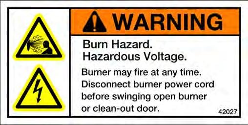
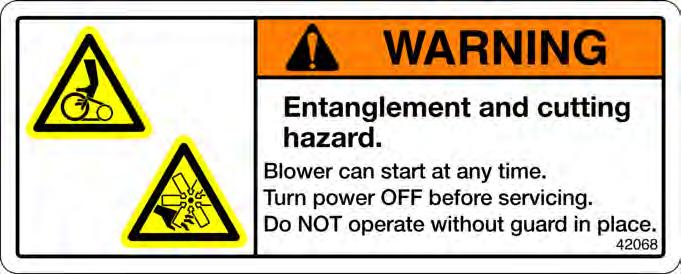
14 Danfoss Type BHO 64 Nr. 057H V 50 60Hz 3W ts 10s Operator's Manual: Models CB-1500 & CB-2500 (230 V / 50 Hz) For Your Safety... (continued) Safety Labels Following are the locations and descriptions of all labels on your CB-1500 or CB-2500 furnace. The following illustrations show the location of ALL labels on your furnace. Please note that some labels denote model number, model description, etc. while others contain important safety messages. Each Safety Label contains an important safety message starting with a key word as discussed earlier in this section (e.g. ATTENTION, CAUTION, WARNING, DANGER). For your safety and the safe operation of your furnace, review all labels and heed all safety messages as printed on the labels. If any labels on your Clean Burn furnace ever become worn, lost or painted over, please call your Clean Burn dealer for free replacements I88888 Label Part # Description Furnace Electrical Shock Hazard Warning Label (several locations) Furnace Burn Hazard/Hazardous Voltage Warning Label Header Label CE Data Label - CB CE Data Label - CB Cleaning Combustion Chamber/Target Caution Label Made in USA / Pat Pending Combination Label Model CB-2500 Label Model CB-1500 Label Furnace Safety Warning Label (Multiple Messages - Fire/Shock/Burn Hazards) Burn Hazard - Hot Surface Warning Label Furnace Blower/Fan Entanglement Hazard Warning Label (near blower) 1-6


15 For Your Safety... (continued) CB-1500/CB-2500 Furnace Cabinet Safety Labels 1-7
16 For Your Safety... (continued) CB-1500/CB-2500 Furnace Cabinet Safety Labels CLEAN BURN, INC. LEOLA, PENNSYLVANIA (USA) CB 2500 BTU/HR (KW) 250, CLEAN BURN, INC. LEOLA, PENNSYLVANIA (USA) CB 1500 BTU/HR (KW) 150, ( 1 mm).04 ( 1 mm) TOP 12 (30) 18 (46) 18 (46) TOP 12 (30) 60 (152) BLOWER 18 (46) 2 (5) 24 (61) DISCHARGE 18 (46) 60 (152) CLOSED 60 (152) 24 (61) BLOWER W/LOUVERS 2 (5) 38 (97) DISCHARGE 60 (152) POWER HZ 50 POWER 3/ HZ 50 1/ / / / / / / / THE MAINTENANCE INTERVAL FOR CLEANING ASH FROM THE FURNACE IS APPROXIMATELY 700 HOURS. THE ASH LEFT FROM THE BURNING OF USED OIL MAY CONTAIN METALLIC COMPOUNDS OR FOREIGN MATERIALS. THE ASH MUST BE DISPOSED OF PROPERLY. THE MAINTENANCE INTERVAL FOR CLEANING ASH FROM THE FURNACE IS APPROXIMATELY 700 HOURS. THE ASH LEFT FROM THE BURNING OF USED OIL MAY CONTAIN METALLIC COMPOUNDS OR FOREIGN MATERIALS. THE ASH MUST BE DISPOSED OF PROPERLY. BURNER REQUIRES A MINIMUM AIR SOURCE OF: 2 S.C.F.M. (57 L/MIN.) AT 25 P.S.I. (1.72 BAR). THIS APPLIANCE IS NOT TO BE USED WITH AIR FILTERS AND SHALL INCORPORATE NO PROVISIONS FOR MOUNTING AIR FILTERS BURNER REQUIRES A MINIMUM AIR SOURCE OF: 2 S.C.F.M. (57 L/MIN.) AT 25 P.S.I. (1.72 BAR). THIS APPLIANCE IS NOT TO BE USED WITH AIR FILTERS AND SHALL INCORPORATE NO PROVISIONS FOR MOUNTING AIR FILTERS NO. MULTI OIL HEATING SYSTEM FOR COMMERCIAL OR INDUSTRIAL USE ONLY
 CB-1500/CB-2500 Burner Labels Label Part # Description 42004 Burner Safety Warning Label (High Voltage/Moving Parts Hazards)")

17 For Your Safety... (continued) CB-1500/CB-2500 Burner Labels Label Part # Description Burner Safety Warning Label (High Voltage/Moving Parts Hazards) Burner Safety Warning Label (Fire/Explosion Hazard - Burner Installation and Service) Burner Model/Serial Number Label Logo/Burner Description Label Reset Warning Label CE Mark Label Burner Power Label Made in USA / Pat Pending Combination Label (on side) Danfoss V 50 60Hz 3W ts 10s Type BHO / Nr. 057H CB-1500/CB-2500 BurnerSafety Labels I
18 1-10
19 SECTION 2: UNPACKING Before assembling your furnace, you must accomplish the following activities described in this section: Removing the Shipping Crate Unpacking and Inspecting All Components Removing the Shipping Crate NOTE: Remove the shipping crate prior to assembly and installation of the furnace. DO NOT use the crate as a platform for furnace installation! 1. Carefully remove the top boards of the shipping crate. Then remove the front, back, and side panels of the shipping crate. 2. Carefully lift the furnace off the shipping pallet with a fork lift. ATTENTION: DO NOT attempt to slide the furnace cabinet out of the shipping crate--you may damage the furnace cabinet. Unpacking and Inspecting All Components Following is an itemized list of all components you should have received in your Clean Burn furnace shipment. Open all shipping containers and inspect all components according to the list. Immediately notify the freight company and your Clean Burn dealer in case of shipping damage or shortage(s). Keep all components together so you will have them as needed for furnace assembly and installation. Furnace Component List ONE SKID containing: Furnace cabinet Items packed inside furnace cabinet (combustion chamber): NOTE: Please refer to the procedure on the following page to remove these items. Target Hot air discharge assembly components plus hardware Furnace accessories: Canister filter Check valve and screen Barometric damper Burner oil line/air line components Assorted bolts/fittings for assembly of furnace components Vacuum gauge Wall thermostat Connector block Operator's Manual ITEMS PACKED IN INDIVIDUAL BOXES: Burner Blower Metering Pump NOTE: You may have received additional boxes or skids if you ordered optional accessories. 2-1
20 Unpacking Items Packed Inside the Furnace To unpack the items packed inside the furnace cabinet (in the combustion chamber), you will need to open the combustion chamber door. 1. Remove the four nuts and washers which hold the combustion chamber door closed. Set the nuts and washers aside in a safe place for later re-installation after the target has been installed (Section 3). 2. Carefully swing the combustion chamber door open. Remove and inspect the components packed inside. 3. Leave the door unfastened (open) for assembly/installation procedures to be accomplished in the next section. CLEAN OUT DOOR COMBUSTION CHAMBER I88881 Figure 2A - Accessing the Combustion Chamber 2-2
21 Understanding Assembly SECTION 3: FURNACE ASSEMBLY Assembling your Clean Burn Furnace includes the following steps: (1) Installing the Blower Assembly (2) Installing the Hot Air Discharge Components (3) Installing the Energy Retention Disc (4) Installing the Burner (5) Installing the Connector Block, Oil Line Tubing, and Air Line Tubing Clean Burn recommends that you review all assembly procedures before proceeding, paying careful attention to safety information statements. Figure 3A on the following page provides a general overview of the furnace components and their proper assembly. Required Tools and Materials The following tools are required for furnace assembly and should be gathered before starting any procedures: 3/8" open-end wrench 9/16" open-end wrench Medium flat-blade screwdriver Medium adjustable wrench 1/4" nut driver attachment for drill Variable speed drill 3-1
22 Danfoss Type BHO 64 Nr. 05 7H V Hz 3W ts 10s AIR OIL Operator's Manual: Models CB-1500 & CB-2500 (230 V / 50 Hz) "ALL THREAD" RODS JUNCTION BOX COUPLINGS FOR "ALL THREAD" RODS BURNER CABLE 4 BURNER MOUNTING BRACKET THROAT R.H. FURNACE BREECH FURNACE DOOR 5 LH FURNACE BREECH WITH CLEAN OUT 1 NOTE: LOOP ON ENERGY RETENTION DISC HOOKS OVER MOUNTING BRACKET ON BACK WALL OF COMBUSTION CHAMBER 3 ENERGY RETENTION DISC INSTALLED ON BACK WALL OF COMBUSTION CHAMBER 2 HOT AIR DISCHARGE FURNACE BREECH NOTICE THE VARIOUS MOUNTING CHOICES FOR THE LOUVERS IT IS OK TO OPEN OR RESTRICT THE LOUVERS AS NEEDED, AND THEN TO TURN THOSE CONFIGURATIONS IN ANY OF FOUR DIRECTIONS I88943 Complete assembly of the CB-1500/CB-2500 furnace according to the following list of activities as illustrated above: (1) Installing the Blower Assembly (2) Installing the Hot Air Discharge Components (3) Installing the Energy Retention Disc (4) Installing the Burner (5) Installing the Connector Block, Oil Line Tubing, and Air Line Tubing NOTE: Corresponding procedures provided in order in this section. Figure 3A - Overview of 2500 Furnace Assembly (CB-1500 is similar) 3-2
23 Installing the Blower Assembly 1. Refer to Figures 3B and 3C. 2. Remove the blower stabilizer brackets as shown in Figure 3B. (These braces, which are installed at the factory, are designed to keep the blower in proper position during shipping. Note that these braces are provided on CB-2500 blower assemblies ONLY; CB-1500 blower assemblies do not require these special shipping braces.) 3. Position the blower over the opening in the back of the furnace cabinet by sliding the blower into the mounting angle brackets. Note that the mounting brackets may be loosened for adjustment, as needed. The blower should be centered over the opening. 4. Fasten the blower to the brackets with self-tapping screws (provided). Drive the screws into the blower housing through the holes in the mounting angle brackets. There are four holes along each side and across the top of the bracket to fasten the blower to the furnace cabinet. 5. Install the blower safety guards as shown. WARNING: To avoid serious personal injury, be sure to install both pieces of the blower guard around the blower prior to operating the furnace. NEVER operate the furnace without all safety shields/guards in place! ATTENTION: The air flow is changed when the guards are not in place which may result in damage to the blower motor. NOTE: For proper air flow through the furnace cabinet the blower must be positioned so that the bulge on the blower faces down as illustrated in Figures 3A, 3B, and 3C REMOVE SHIPPING BRACES ATTACH BLOWER TO FURNACE X 2 I88691 D Figure 3B - Installing the Blower Assembly 3-3
24 Installing the Blower Assembly (continued) Black Motor Lead Orange Wire White Motor Lead White Wire Brown Motor Leads Capacitor Green Wire Ground Screw Note: CB-1500 is shown; CB-2500 Junction Box and Motor are mounted on the opposite side of the blower. I89017 Wiring the Blower Motor Figure 3C - Blower Installed on Furnace Cabinet WARNING: Make sure the main power to the furnace is turned OFF before wiring the blower motor. NOTE: For reference, wiring schematics are provided in Appendix B at the back of the manual. 1. After the blower has been secured to the back of the furnace cabinet, install the electrical conduit with the blower motor leads into the 4" x 6" rear junction box on the top of the furnace cabinet as shown in Figure 3C. Connect the power lead coming from the blower assembly to the 4" x 6" electrical box mounted on the rear of the furnace cabinet. Connect the black (power) motor lead wire to the connector block terminal with the orange (power) wire from the front electrical box. Connect the white (neutral) motor lead wire to the connector block terminal with the white (neutral) wire from the front electrical box. Connect the two brown leads to the capacitor and mount it inside the electrical box with the strap provided. 3-4
25 Determining the Hot Air Discharge Configuration Before proceeding with the assembly of your furnace, it is important to determine the configuration of the air discharge for your furnace. There are three configurations to consider for the CB-2500 and two possible configurations for the CB-1500: (1) Unit Heater Furnace with blower assembly for FREE AIR applications. CB-1500 and Follow the instructions (provided in this section) to install the blower CB-2500 assembly and air discharge components. Be sure to adhere to the proper specified clearances for Unit Heater Configurations as stated in Section 4 of this manual. CB-1500 CB-2500 Equipped with two (2) louver sections and four (4) blank cover panels Equipped with three (3) louver sections and three (3) blank cover panels (2) Central Furnace (A) Furnace with blower assembly for DUCTING applications with 0.06 kpa CB-1500 and (0.25 "WC) or less static pressure.* CB-2500 Follow the instructions to install the blower assembly, and refer to the following chart for the proper air discharge and ducting specifications. Be sure to adhere to the proper specified clearances for Central Furnace Configurations as stated in Section 4 of this manual. CB-1500 CB-2500 Do not install louvers. Ductwork should be installed directly over the desired air discharge opening on the side of the furnace cabinet (305 mm x 305 mm). Determine which side of the furnace cabinet will have the ductwork attached. Replace the left or right side inner shield and shrouding to accommodate the ductwork. Do not install louvers. Ductwork should be installed directly over the desired air discharge opening on the side of the furnace cabinet (395 mm x 395 mm). #29184 Inner Shield Right #29186 Right Side Shrouding #29185 Inner Shield Left #29187 Left Side Shrouding Install an additional blank cover panel to close off the remaining air discharge opening. #29115 Cover Discharge Closure Panel (3) Central Furnace (B) Furnace with blower assembly for DUCTING applications from 0.06 kpa CB-2500 ONLY (0.25 "WC) to 0.10 kpa (0.40 "WC) static pressure.* Follow the instructions to install the blower assembly, and refer to the following chart for the proper air discharge and ducting specifications. Be sure to adhere to the proper specified clearances for Central Furnace Configurations as stated in Section 4 of this manual. CB-2500 Same as above - Central Furnace (A) 3-5
26 Determining the Hot Air Discharge Configuration (continued) Air Flow - Cubic Meters per Minute (CMM) or Cubic Feet per Minute (CFM) and Static Pressure (SP) Specifications CB-1500 Air Discharge Louvers Mounted on Furnace Free Air* 40 CMM (1400 CFM) Air Discharge Louvers Removed With Ductwork Installed on Furnace 0.06 kpa* (0.25 INCHES WC) 34 CMM (1200 CFM) CB-2500 Air Discharge Louvers Mounted on Furnace Free Air* 71 CMM (2500 CFM) Air Discharge Louvers Removed With Ductwork Installed on Furnace 0.06 kpa* (0.25 INCHES WC) 68 CMM (2400 CFM) Air Discharge Louvers Removed With Ductwork Installed on Furnace 0.10 kpa* (0.40 INCHES WC) 64 CMM (2250 CFM) *ATTENTION: A qualified electrician must check the blower motor amperage during operation of the furnace to ensure that motor amperage does not exceed 85% of the maximum amperage on the motor label. DO NOT operate the blower motor above 85% of maximum amperage or motor damage may occur. IMPORTANT NOTE: It is essential that qualified HVAC personnel properly design the ductwork for your furnace and determine the static pressure for your ducting application. Note that existing ductwork at your installation site may not be appropriate or meet the specifications for this furnace installation. For static pressure readings as shown in the chart above, the ductwork should be installed directly over the opening in the SIDE of the furnace cabinet (i.e. where the louver panels would be installed for free air applications.) For Central Furnace applications, ductwork may NOT be installed over the bottom opening. Installing the Hot Air Discharge Components It is very important to properly install the hot air discharge components (louvers and blank cover panels) to direct the flow of air from the furnace. As you will note from Figures 3D and 3E, the air discharge panels are to be installed on the side(s) and/or bottom of the furnace. The air flow may be directed down, front, or back depending on how the louvers and cover panels are installed. IMPORTANT NOTE FOR CENTRAL FURNACE APPLICATIONS: For ducting applications with static pressure, DO NOT install the louvers. The ductwork should be installed directly over the desired air discharge opening on the side of the furnace cabinet. CB-1500 opening in side shrouding for ductwork mm x 305 mm (12" x 12") NO changes need to be made for the shrouding outlet size CB-2500 opening in side shrouding for ductwork mm x 395 mm (15 1/2" x 15 1/2") Install new inner shield and outside shrouding with larger opening sizes Ductwork must be installed over side opening(s) ONLY. Ductwork may NOT be installed over the bottom air discharge opening. 3-6
27 Danfoss Hz 3W ts 1 0s Ty p e BHO 6 4 Nr H70 36 D anfo Type BHO 6 4 Nr. 05 7H Operator's Manual: Models CB-1500 & CB-2500 (230 V / 50 Hz) Installing the Hot Air Discharge Components (continued) 1. Refer to Figures 3D and 3E. Determine the desired air flow discharge pattern. Note that the CB-1500 is supplied with (2) louver sections and (4) blank cover panels. The CB-2500 is supplied with (3) louver sections and (3) blank cover panels. Air discharge openings are: (1) on each side of the furnace, and (1) on the bottom of the furnace. 2. Install the louver panels in the desired location(s) with the self-tapping screws provided. Holes are pre-drilled in the furnace cabinet to accommodate installation of the panels. 3. Adjust the louvers for the desired air flow direction. ATTENTION: DO NOT restrict the flow of the hot air from the furnace by closing the louvers, or the furnace will not operate properly. 4. Install the blank covers over the remaining air discharge opening(s) on the furnace cabinet. Air Flow Discharge Installation Guidelines: When determining the placement of the air discharge louvers, you also need to consider the required clearances from combustibles as stated in Section 4 of this manual. Note that the CB-1500 is supplied with (2) louver sections which may be installed together on one side or the bottom OR the louvers may be split for partial air discharge on each side and/or bottom. If a side contains only one louver section it should be mounted on the upper portion H z 3W ss ts 10s NOTE: Bottom louver installation applies to Unit Heater furnaces ONLY. Ductwork for Central Furnace applications may NOT be installed over the bottom opening. CB-2500 IS SHOWN (CB-1500 IS SIMILAR) I88944 Figure 3D - Hot Air Discharge Components (Louvers/Blank Covers) Installed on Furnace 3-7
28 Installing the Hot Air Discharge Components (continued) Louvers split between two side openings, showing left and right side views of same furnace NOTE: When louver panels are "split" between two sides, make sure the louvers are installed in the upper half of each side air discharge opening as shown here. Louvers split between left side and bottom openings, showing left and right side views of same furnace NOTE: When louver panels are "split" between a side and the bottom, make sure the bottom louvers are installed in the forward half of the bottom air discharge opening as shown here. Louvers split between both sides and bottom openings, showing left and right side views of same furnace I88945 Figure 3E - Sample Split Louver Installations for Partial Air Discharge on Sides and/or Bottom. CB-2500 is shown. CB-1500 is similar with two (2) louver sets and four (4) blank cover panels. 3-8
29 Installing the Energy Retention Disc Installing the Energy Retention Disc at the Back of the Combustion Chamber ATTENTION: DO NOT fire your furnace without the Energy Retention Disc in place, or combustion chamber damage will occur. Handle the Energy Retention Disc carefully to avoid damaging it. 1. Refer to Figure 3A to review the proper positioning of the Energy Retention Disc. 2. Swing open the clean-out door on the furnace front to gain access to the combustion chamber. 3. Use a long rod to support the Energy Retention Disc as you guide it into position on the back of the combustion chamber. The loop on the back of the Energy Retention Disc fits over the hook located on the back of the combustion chamber. Closing the Furnace Door 1. After the Energy Retention Disc has been installed, close the furnace clean-out door. 2. Tighten the four (4) lock-down nuts in a criss-cross pattern until all are snug. Installing the Burner Checking the Burner Nozzle and Electrodes NOTE: The burner nozzle is factory installed. Both furnace models (CB-1500, CB-2500) use a Delavan 9-5 nozzle. The nozzle size is indicated on the nozzle as shown in Figure 3F on the following page. Refer also to Appendix A at the back of the manual for additional specifications/instructions on the burner nozzle. ATTENTION: Check the electrode settings as specified in Figure 3F. The electrode settings must be correct for your burner to operate properly. 3-9
30 Installing the Burner (continued) BURNER NOZZLE NOZZLE IS STAMPED WITH SIZE ON FLAT OF NOZZLE HEAD SIDE VIEW AA 5 mm (3/16") GAP BETWEEN ELECTRODES & NOZZLE 3X CRITICAL DIMENSION: NOZZLE MUST BE 3 mm (1/8") AHEAD OF THE DISK. NOZZLE MUST NOT BE BEHIND THE DISK. VIEW BB VIEW AA 3 mm (1/8") SPARK GAP FRONT VIEW BB I88906 Figure 3F - Burner Nozzle and Electrode Specifications 3-10
31 Installing the Burner (continued) Mounting the Burner on the Hinge Bracket ATTENTION: Burner tube components (e.g. electrodes and retention head) are factory set. Handle the burner with extreme care so that burner components are not damaged. 1. Remove the nut from the mounting flange of the furnace cabinet, and set it aside for later use. 2. Lift the burner into position so that it is mounted on the hinge bracket on the furnace cabinet. 3. Carefully swing the burner so the retention head enters the throat of the furnace. 4. Check the clearance between the retention head and the furnace throat. There must be at least 1/8" clearance, so the retention head is not "bumped" as you swing the burner into firing position. NOTE: If the retention head "bumps" the furnace throat, adjust the hinge bracket bolts as follows: While supporting the burner, slightly loosen the two (2) hinge bracket bolts. Carefully re-position the burner so it swings freely into its firing position. With the burner in its firing position, re-tighten the hinge bracket bolts. 3-11
32 Danfoss Type BHO 64 Nr. 057H7036 ts 10s V 50-60Hz 3W Operator's Manual: Models CB-1500 & CB-2500 (230 V / 50 Hz) Installing the Connector Block, Oil Line Tubing, and Air Line Tubing ATTENTION: DO NOT use teflon tape on any fittings. Teflon tape residues will plug vital burner components. Installing the Connector Block on the Furnace Door 1. Refer to Figure 3G. 2. Use the two (2) bolts to install the aluminum connector block onto the furnace cabinet. 3. Remove and discard the red caps and plugs from the fittings and ports on the connector block. DO NOT allow any dirt/debris to enter these components during furnace assembly. OIL LINE OIL FITTING ON BURNER ATTENTION: The connector block includes an accumulator. The accumulator functions like a shock absorber on the oil line to prevent pressure buildup and protect vital burner components. It is important that the connector block is installed as shown so that the accumulator is in a vertical position to prevent sediment from settling in the accumulator. Never operate your furnace without the connector block and accumulator properly installed on the furnace, or damage may occur to vital burner components. Installing the Oil Line Tubing CONNECTOR BLOCK FRONT VIEW OF FURNACE AIR OIL LINE FITTING ON BURNER LINED UP WITH OIL LINE OIL LINE OIL ATTENTION: DO NOT disassemble the compression fitting from the swivel fitting. To prevent leaks, the NPT threads of the compression fitting have been sealed with hydraulic sealant during assembly of the fittings at the factory. 1. Remove and discard the red caps from the oil line tubing. 2. Loosely install the oil line tubing into the oil line fitting on the burner. SWIVEL ASSEMBLY CONNECTOR BLOCK SIDE VIEW OF FURNACE SHOWING OIL LINE INSTALLED Figure 3G - Installation of Connector Block and Oil Line 3. Use a wrench to slightly rotate the oil line fitting on the burner counterclockwise so the tubing lines up with the swivel assembly. Slightly bend the tubing as shown in Figure 3H, if required, to "line up" the oil line. 4. If necessary, use a tubing cutter to cut the tubing to the proper length. ATTENTION: Due to adjustment of the burner hinge bracket, the oil line tubing may need to be cut to fit properly. DO NOT lift up on the burner when installing the oil line tubing to compensate for oil line tubing that is too long. This will place the weight of the burner on the swivel fitting and result in leaks at the swivel fitting seal. I
33 Nr. 057H7036 Type BHO V 50-60Hz 3W ts 10s Operator's Manual: Models CB-1500 & CB-2500 (230 V / 50 Hz) Installing the Connector Block, Oil Line Tubing, and Air Line Tubing (continued) Installing the Oil Line Tubing (continued) 5. Make sure that the curl in the oil line is positioned as shown in Figure 3G so that the burner can swing open correctly. 6. Install the oil line tubing and tighten the nuts on the compression fittings. DO NOT overtighten these fittings to avoid damaging the ferrules. NOTE: You may also check the positioning of the oil line according to Figure 3H which provides a larger front view of the connector block assembly. Installing the Air Line Tubing 1. Remove and discard the red caps from the air line tubing. 2. Refer to Figure 3H. Push the air line tubing into the swivel fitting on the connector block until the tubing bottoms out in the fitting. 3. Repeat this procedure to connect the air line tubing to the air line fitting on the side of the burner. CB-1500 is shown CB-2500 is similar AIR LINE FITTING ON BURNER OIL LINE FITTING ON BURNER Danfoss AIR LINE OIL LINE COMPRESSION / SWIVEL FITTING AIR OIL I88887 CONNECTOR BLOCK INSTALLED ON FURNACE CABINET Figure 3H - Installation of Connector Block, Oil Line and Air Line (Front View) 3-13
34 Locking the Burner Into Firing Position 1. Swing the burner into firing position. 2. Install and tighten the lock-down nut on the mounting plate bolt to secure the burner in its firing position. 3. Plug the burner electrical cable into the receptacle on the top of the burner housing. 4. Tighten the locking ring to secure the electrical cable. PLUG ON CAM LOCK CABLE NOTE: Be sure to properly align the plug when plugging it into the receptacle. See Fig 3I. SLOT IN PLUG MUST ALIGN WITH SLOT IN RECEPTACLE RECEPTACLE ON TOP OF BURNER I88354A Figure 3I - Detail of Burner Electric Receptacle NOTE: Your furnace is now assembled and ready for installation. Install the furnace as soon as possible so the burner and/or blower are not "bumped" or damaged. If you must store the furnace for a period of time before installation, make sure it is located in a safe, secure area. 3-14
35 SECTION 4: FURNACE INSTALLATION Understanding Installation Installing your Clean Burn furnace is a multi-step process which includes: (1) Selecting a Location (2) Mounting the Furnace (3) Oil Tank Installation Specifications (review) (4) Installing the Metering Pump (5) Wiring the Furnace and Pump (6) Installing the Oil Lines (7) Installing the Compressed Air Line (8) Installing the Stack (9) Installing the Wall Thermostat (10) Inspecting the Installation Clean Burn recommends that you review all procedures before beginning installation, paying careful attention to safety information statements. Figures 4A and 4B provide a general overview of a typical furnace installation and should be reviewed closely before proceeding. WARNING: Improper installation can adversely affect the proper, safe operation of your furnace. It is critical that your furnace installer reads and follows the instructions provided in this manual. Access to the furnace must be restricted; only trained, qualified personnel should be permitted to perform installation and operation procedures. WARNING: To prevent damage to the furnace and to ensure personal safety, lifting, mounting, and hanging of the furnace must be performed in accordance with safe handling procedures. Important Safety Guidelines for Safe Installation General installation of the appliance shall be in accordance with the manufacturer's literature, in addition to complying with the following: BS5410 Code of Practice for Oil Firing 1997: Installation up to 45 KW output capacity for space heating and hot water supply purposes. 1998: Installation of 44 KW and above capacity for space heating, hot water and steam supply purposes. 1978: Installation for furnaces, kilns, ovens and other industrial purposes. The Building Regulations: England and Wales: Approved Document J: Heat Producing Appliances (1991). Scotland: Technical standards for compliance with the Building Standard (Scotland) Regulations 1990, Part F: Heat Producing Installations and Storage of Liquid and Gaseous Fuels. Northern Ireland: The Building Regulations (Northern Ireland) Technical Booklet L - Heat Producing Appliances, July Republic of Ireland: The Building Regulations of Ireland 1997, Part J: Heat Producing Appliances. Isle of Man, Jersey and Guernsey: The Building Bylaws - BS 7671: 1992 IEE Wiring Regulations 16th Edition. 4-1
36 Important Safety Guidelines for Safe Installation (continued) The Environmental Protection Act 1990, Part 1: Processes prescribed for air pollution control by local enforcing authorities PG1/1 (95). Secretary of State's Guidance: Waste Oil Burners, less than 0.4 MW net rated thermal input. November 1995 (Appendix A of OFTEC OFSA 103). OFTEC Guidelines: Document OFG100 for externally serviced oil fired appliances. Important Notes to the Electrician WARNING: Electrical installation of the furnace is to be performed only by qualified personnel (i.e. licensed electrician/engineer). Improper electrical installation can adversely affect the proper, safe operation of the furnace and may cause serious personal injury/death. WARNING: Before completing any furnace wiring, refer to the wiring diagrams in Appendix B at the back of the manual. Carefully review the wiring assignments and colors, noting that the Clean Burn wire colors may not be "standard" or familiar. WARNING: High earth leakage current / earth connection is essential and must be established before connecting the main power supply. WARNING: Low voltage terminals are only protected by basic insulation--caution is required. CAUTION: Use only approved wire conduit and connectors when wiring the Clean Burn furnace. An emergency stop device (i.e. "panic button") must be installed at ground level in the mains cable to the furnace to ensure the safety of furnace operators and service personnel. The external disconnect device must employ a contact separation of 3mm in all poles; the external breaker must be an approved type. CAUTION: The main cable must be introduced into the control box using conduit connectors which provide adequate strain relief. The main cable installation must be accomplished using suitably rated and approved wiring (BASEC or HAR) or appropriate current-carrying capacity. The wires should have a minimum rating of 90 degrees C. NOTE: According to Clause 4A of (International Electrical Standard), the user must determine, in consultation with the supply authority, that the furnace is connected only to a supply with an impedance of x x 10-3 or less. 4-2
37 Danfoss V Hz 3W ts 10s Type BHO 64 Nr. 057 H7036 AIR OIL Operator's Manual: Models CB-1500 & CB-2500 (230 V / 50 Hz) WARNING! NEVER LOCATE A STACK JOINT INSIDE WALLS OR IN A JOIST SPACER. DO NOT CREATE FIRE HAZARDS! NOTE: THE LAST STACK SECTION SHALL EXTEND AT LEAST 92 cm (3 FT) ABOVE THE HIGHEST POINT AT WHICH IT COMES IN CONTACT WITH THE ROOF, AND AT LEAST 61 cm (2 FT) HIGHER THAN ANY RIDGE, PARAPET OR ROOF STRUCTURE WITHIN 3 m (10 FT) OF IT. 3 m (10 FT) 61 cm (2 FT) WARNING! FOLLOW LOCAL CODES AND STACK MANUFACTURER S SPECIFICATIONS TO ENSURE SAFE CLEARANCES BETWEEN STACK COMPONENTS AND COMBUSTIBLES WARNING: When installing your furnace, adhere to the clearances from combustible surfaces as stated in Section 4, 3 m (10 FT) MIN. VERTICAL STACK HEIGHT These clearances also provide adequate space for servicing. Failure to maintain proper clearences may result in fire, explosion, personal injury or death. CONNECTOR BLOCK STACK SIZE: MIN. 20 cm (8 IN.) CLEAN BURN RECOMMENDS THAT HORIZONTAL STACK NOT EXCEED 60% OF VERTICAL STACK LENGTH 244 cm (8 FT) MIN. FROM FLOOR TO FURNACE IF THERE IS A POTENTIAL FOR GASOLINE FUMES IN YOUR SHOP. CHECK LOCAL CODES. MAXIMUM 183 cm (6 FT) CAUTION: DO NOT EXCEED 183 cm (6 FT) VERTICAL SUCTION LIFT OR THE PUMP WILL NOT PRIME AND/OR THE FLOW RATE FROM THE PUMP MAY DECREASE COMPRESSED AIR LINE EMERGENCY VENT VALVE FUNNEL WITH BALL VALVE CONTINUOUS PIECE OF COPPER TUBING INSIDE TANK: 16 mm (5/8") O.D. BALL VALVE RADIAL BEND MADE WITH TUBING BENDER INSTALL SLIP FITTING TO HOLD TUBING IN PLACE VENT CAP CHECK VALVE IS MINIMUM 305 mm (12 IN.) OFF TANK BOTTOM TO CREATE SLUDGE TRAP I88890 B Figure 4A - Typical CB-2500 Furnace Installation (CB-1500 is similar) 4-3
38 Danfoss V Hz 3W ts 10s T ype BHO 64 Nr. 057H7036 AIR OIL Operator's Manual: Models CB-1500 & CB-2500 (230 V / 50 Hz) NON RESTRICTIVE "CLASS A" STACK CAP "CLASS A" STACK INSULATED STACK WITH STAINLESS STEEL LINER CEILING MOUNTING SYSTEM WARNING! MAKE SURE TO INSTALL THE PROPER ROOF SUPPORT SYSTEM TO SAFELY SUPPORT THE STACK WARNING! USE MINIMUM 64 mm X 64 mm X 6 mm (2 1/2 X 2 1/2 X 1/4") ANGLE IR0N BEAMS, BRIDGED ACROSS SUFFICIENT STRUCTURAL MEMBERS TO ANGLE IRON SUPPORT SAFELY SUPPORT FURNACE BEAMS DOUBLE NUTS WARNING! OUTSIDE STACK AND STACK PENETRATIONS THROUGH CEILING, ROOF OR SIDEWALL MUST BE "CLASS A" FOR FIRE SAFETY AND TO MAINTAIN PROPER DRAFT EXTERIOR SINGLE WALL STACK DOES NOT MEET CODE. EXTERIOR SINGLE WALL STACK CHILLS THE EXHAUST GASES RESULTING IN POOR BURNER PERFORMANCE AND BACK PRESSURE IN THE FURNACE WATERTIGHT ROOF FLASHING: CLEAN BURN RECOMMENDS "DEKTITE" FLASHING FOR A WATERTIGHT SEAL (4) 5/8 "ALL THREAD" SUPPORT RODS THREAD SUPPORT RODS TO COUPLING NUTS IN FURNACE CABINET WARNING! MAKE SURE TO USE LOCKNUTS WHEN FASTENING THE RODS TO THE COUPLING NUTS DEDICATED ELECTRIC CIRCUIT AIR DISCHARGE CHECK FOR.02 W.C. DRAFT OVERFIRE AT SIGHT PLATE "2 WIRE" MIN 18 GA. THERMOSTAT CABLE L.H. FURNACE BREECH WITH CLEAN OUT CAP INSTALLED CONNECTOR BLOCK COMPRESSED AIR LINE SINGLE WALL STACK MINIMUM 24 GAUGE BAROMETRIC DAMPER: INSTALL ON STACK 305 mm (1 FT) TO 915 mm (3 FT) FROM FURNACE BREECH OIL FLOW R. H. FURNACE BREECH "CLASS A" KIT FOR INSTALLING "CLASS A" STACK THROUGH CEILING 1/4" HOLE FOR SETTING DRAFT. ADJUST BAROMETRIC DAMPER FOR.04 W.C. DRAFT AT BREECH ELBOW OR CLEAN OUT TEE OIL PUMP ELECTRICAL CIRCUIT ELECTRIC SERVICE 24 VOLT WALL THERMOSTAT FUNNEL WITH BALL VALVE CAUTION: SUCTION OIL LINE MUST BE 100% AIRTIGHT. AIR LEAKS CAUSE THE BURNER TO PERIODICALLY SHUT DOWN ON SAFETY LOCKOUT EMERGENCY VENT VALVE SUCTION LINE PRESSURE OIL LINE BALL VALVE FLARE FITTING CANISTER FILTER IN SUCTION LINE NOTE: MAKE SURE IS IN THE SAME DIRECTION AS VENT PIPE WITH VENT CAP CHECK VALVE SCREEN CHECK VALVE INSTALL WITH ARROW UP CLEAN OUT OIL STORAGE TANK I88891 B Figure 4B - Typical CB-2500 Furnace Installation - Detailed (CB-1500 is similar) 4-4
39 Selecting a Location Guidelines for Selecting a Location The location you select for your furnace must allow the following: Unobstructed, even heat distribution. Safe, easy access for servicing. Unobstructed passage for shop vehicles and equipment. Proper clearances from combustibles. Verify according to your local safety codes. Adequate combustion air per local codes. Proper stack installation. WARNING: Adhere to the following minimum clearances from combustible surfaces and to provide adequate clearance for servicing (also refer to Figure 4C); failure to maintain proper clearances may result in fire, explosion, personal injury or death. CLEARANCES FOR UNIT HEATER INSTALLATION WITH SIDE AIR DISCHARGE TOP (of furnace) cm (12") FRONT (burner) cm (60") SIDE with Air Discharge cm (60") OTHER SIDE cm (18") CHIMNEY CONNECTOR cm (18") REAR (from blower)... 5 cm (2") BOTTOM cm (24") CLEARANCES FOR CENTRAL FURNACE INSTALLATION TOP (of furnace) cm (12") FRONT (burner) cm (60") SIDE without stack cm (18") CHIMNEY CONNECTOR cm (18") REAR (from blower)... 5 cm (2") BOTTOM cm (24") WARM AIR DUCTS cm (6") within 92 cm (3ft) CLEARANCES FOR UNIT HEATER INSTALLATION WITH BOTTOM AIR DISCHARGE TOP (of furnace) cm (12") FRONT (burner) cm (60") SIDE (with or without stack) cm (60") CHIMNEY CONNECTOR cm (18") REAR (from blower)... 5 cm (2") BOTTOM with Air Discharge cm (38") WARNING: Your local codes may require that your furnace is mounted a minimum of 244 cm (8 ft.) off the ground if there is the possibility of gasoline fumes or other combustible or explosive fumes in your shop area. Refer to Figure 4C on the following page for an illustration of proper clearances from combustibles. 4-5
40 Danfoss Type BHO 64 Nr. 05 7H703 6 ts 1 0s Operator's Manual: Models CB-1500 & CB-2500 (230 V / 50 Hz) Selecting a Location (continued) 5 cm (2") REAR 31 cm (12") TOP 46 cm (18") OTHER SIDE (WITHOUT AIR DISCHARGE) 46 cm (18") CHIMNEY CONNECTOR Hz 3 W 153 cm (60") AIR DISCHARGE SIDE 244 cm (96") BOTTOM, IF THERE IS POTENTIAL FOR GASOLINE FUMES 61 cm (24") BOTTOM, IF THERE IS NO POTENTIAL FOR GAS FUMES (NOTE: 97 cm (38") FOR BOTTOM AIR DISCHARGE) 153 cm (60") FRONT I88946 Figure 4C - Clearances from Combustibles Mounting the Furnace After selecting a safe and appropriate location for your furnace, construct the mounting system as required by the location and the following specifications. Ceiling Mounting WARNING: To prevent serious personal injury, ensure that your furnace mounting system can safely bear the suspended weight of the furnace and allow safe servicing of furnace components. Use adequately sized square tubing or angle iron bridged across sufficient structural members to safely support the furnace. 1. Refer to Figures 4A and 4B. 2. Follow the instructions as provided in the diagrams. 3. Use a spirit level to make sure the cabinet is level side to side and front to back. 4-6
41 Danfoss Type BHO 64 Nr. 057H V 50-60Hz 3W ts 10s AIR OIL Danfoss V 50-60Hz 3W ts 10 s Type BHO 64 Nr. 057H7036 AIR OIL Operator's Manual: Models CB-1500 & CB-2500 (230 V / 50 Hz) Mounting the Furnace (continued) Raised Platform Mounting WARNING: To prevent serious personal injury, make sure the platform is designed to safely bear the weight of the furnace and allow safe servicing of furnace components. The platform must be constructed of non-combustible materials (e.g. steel) and must be securely anchored to an adjacent wall. 1. Refer to Figure 4D, and follow the instructions as provided in the diagram. Floor Mounting WARNING: To prevent serious personal injury, make sure the floor can safely bear the weight of the furnace. CAUTION: If you are installing your furnace in an area with a combustible floor, you must construct a non-combustible floor as shown in Figure 4E. NOTE: Make sure that blank cover panels are installed over the bottom air discharge opening to allow safe floor mounting. 1. Refer to Figure 4E and follow the instructions as provided in the diagram. I88893 Figure 4D - CB-1500 Furnace Installed on a Raised Platform (CB-2500 is similar) MIN. 24 GA STEEL PAN WITH MIN. 2.5 cm (1") LIP FOR OIL CONTAINMENT 46 cm (18") 46 cm (18") 20 cm (8") MIN. TALL CINDER BLOCK 1 PIECE MIN. 24 GA STEEL 2 PIECES FIREGUARD SHEETROCK OR EQUIVALENT COMBUSTIBLE MATERIAL MIN. 5 cm (2") TALL MASONRY BLOCKS TO ALLOW CLEARANCE FOR INSTALLATION OF FITTINGS ON THE CONNECTOR BLOCK I88894 Figure 4E - CB-1500 Furnace Installed on Non-Combustible Floor (CB-2500 is similar) 4-7
 also summarizes these important specifications for tank installation and usage.")
42 Oil Tank Installation Specifications Ensure that your tank installation adheres to the following safety guidelines as stated here and in Section 1 of this manual. The tank safety label (shown at right) also summarizes these important specifications for tank installation and usage. If you do not have a copy of this label, please contact your Clean Burn dealer for a copy, which is to be affixed directly to your used oil supply tank. The tank installation must meet all national and local codes. Consult your local municipal authorities for more information as necessary. Use a minimum 1000 Liter tank. DO NOT use drums as a substitute for an appropriate tank. The tank must be large enough to allow water, sludge, etc. to settle out of the used oil. Single wall tanks must have a shut-off valve on the side of the tank to allow the water, sludge, etc. to be drained from the bottom of the tank. All unused openings in the tank must be plugged or capped off. For optimal system functioning, Clean Burn Recommends inside tank installations as shown in Figures 4A, 4B, and 4J. The tank must be vented to the outside of the building using iron or steel pipe and fittings with an approved vent cap. Carefully review the oil tank and pump installation details as shown in Figures 4A, 4B, 4F, and 4J including the metering pump installation and specifications for the oil line installation. (Procedures for installing these components can be found in the following pages.) Ensure that the oil supply tank is properly maintained; refer to Section 9 in this manual for related procedures. ATTENTION: For outside tank installations and/or tanks larger than 1890 Liters (500 gallons), contact the local Clean Burn distributor for installation recommendations and specifications. 4-8
43 Oil Tank Installation Specifications (continued) TANK VENT KITS AVAILABLE FROM CLEAN BURN: CB Part # " Tank Vent Kit (2) elbows (2) 6" nipples (1) mushroom cap vent (1) emergency vent MUSHROOM CAP VENT PRESSURE RELIEF OIL LINE BACK TO THE TANK PRESSURE LINE PUMP STEEL PIPE (USER SUPPLIED) FUNNEL WITH BALL VALVE SUCTION LINE ASSEMBLY EMERGENCY VENT CHECK VALVE FILTER SCREEN CLEAN OUT (TANK DRAIN) Figure 4F - Typical Metering Pump Installation with Inside Tank Installing the Tank Vent and Emergency Vent Codes require that you install a tank vent (to the outside) and an emergency vent for your tank as shown in Figure 4F. Tank Vent Kits are available from Clean Burn; contact your local Clean Burn dealer to order. Be sure to check your local codes for any additional tank installation requirements, and adhere to the following installation guidelines: Install a length of minimum 5 cm (2") steel pipe (user-supplied) terminating outside with a proper vent cap as shown in Figure 4F. Consult local codes for information and requirements concerning the proper venting of oil storage tanks. Install an emergency vent as shown in Figure 4F. Contact your tank manufacturer for information concerning the proper emergency vent for your tank. 4-9
44 Installing the Metering Pump Preparing for Installation Before starting installation of the metering pump, review Figures 4G, 4H, and 4I to become familiar with the metering pump components. You will also need to accomplish the following activities: Verify that you have the proper metering pump for your furnace (note the specific gear motor part numbers shown in Figure 4H). Gather all required tools and materials as needed for installation; as indicated in the following procedures, some materials (e.g. fittings, tubing) are to be user-supplied. Standard mounting is vertical mounting on a wall; this pump installation is recommended. Alternate mounting is horizontal mounting on a bracket. Be sure to carefully follow the appropriate procedures/diagrams for pump mounting. For optimal metering pump functioning, mount the pump at a distance from the oil tank that will comply with the following requirements: The suction oil line may NOT exceed 183 cm (6') TOTAL vertical lift AND 122 cm (4') TOTAL horizontal lift. Standard Mounting: Vertical Positioning 1. Refer to Figures 4G, 4H, and 4I. Note that the metering pump is shipped with the pump head already positioned for vertical wall mounting. 2. Use the appropriate type of bolts and washers (user-supplied) to securely mount the metering pump to the appropriate wall in your building at a distance from the tank that complies with the suction oil line requirements. Figure 4G - Standard (Recommended) Vertical Mounting of the Metering Pump 4-10
45 # PART # DESCRIPTION 2 see chart GEARMOTOR MOUNT METER PUMP /8 NPT X 1/4 TUBE COMPRESSION FITTING 5 N/A 1/4 COPPER OR ALUM. TUBING LONG NUT 1/2 7 N/A 1/2 COPPER OR ALUM. TUBING FLARED TUB. TO PIPE STRAIGHT 1/2 X 1/2NPT MINI BALL VALVE 1/8 MNPT X 1/8 FNPT METER PUMP /4" X 3" NIPPLE /4" STREET ELBOW /4" X 3/4" BRASS BUSHING VACUUM GAUGE CANISTER FILTER LENZ /2" x 3/4" BUSHING, BRASS /2" X 5" NIPPLE /2" STREET TEE, BRASS /2" HEX NIPPLE /2" BALL VALVE /4" NPT x 1/4" TUBING FITTING /4" x 1/2" BUSHING /2" NPT x 1/2" TUBING FLARE ADAPTER /2" LONG NUT /2" NPT x 1/2" TUBING SLIP ADAPTER " x 1/2" x 1/2" NPT DUPLEX HEX BUSHING /4" CHECK VALVE /4" CHECK VALVE SCREEN /2" PIPE CAP PIPE REDUCER 1/2 1/4 BRASS HEX /8 MNPT X 1/4FNPT Figure 4H - Metering Pump Component Detail 4-11 CLEAN BURN MODEL CB 1500 CB 2500 CB 3500 CB 5000 CB 200 CTB CB 350 CTB CB 500 CTB GEARMOTOR PART # I88728 F
46 ROTA TION ROTATION ROTATION Operator's Manual: Models CB-1500 & CB-2500 (230 V / 50 Hz) Installing the Metering Pump (continued) Alternate Mounting: Horizontal Positioning ATTENTION: If the metering pump is to be mounted horizontally or on a bracket as shown in Figure 4I, the pump head must be rotated counterclockwise so that it is aligned in a horizontal position. The gauge arrow on the pump head must point up, or the pump will not prime. 1. Refer to Figures 4H and 4I. 2. Remove the two pump mounting bolts. The coupling is keyed and does not have set screws. 3. Rotate the pump head 180 degrees to the horizontal position as shown in Figure 4I. 4. Re-install and tighten the two pump mounting bolts. 5. Use the appropriate type of bolts and washers (user-supplied) to securely mount the metering pump to the mounting bracket, which is to be installed on the appropriate wall in your building at a distance from the tank that complies with the suction oil line requirements. GAUGE RELIEF A2RA 7720 INLET ROTATION GAUGE RELIEF A2RA 7720 INLET GAUGE RELIEF A2RA 7720 INLET GAUGE RELIEF A2RA 7720 INLET RECOMMENDED SETUP PUMP IS MOUNTED LEFT ON WALL I88708 B INLET INLET ALTERNATE MOUNTING (NOT RECOMMENDED) BLEED VALVE IS NOW CLOSE TO THE WALL MAKING THE BLEEDING DIFFICULT INLET NON STANDARD SETUP PUMP HEAD HAS BEEN ROTATED 90 CCW FOR HORIZONTAL MOUNTING (THE 1/4" STREET ELBOW AND 1/4" X 3" NIPPLE CHANGE PLACES IN THE PLUMBING SEQUENCE) Figure 4I - Proper Positioning of Metering Pump Head 4-12
47 Wiring the Furnace and Pump WARNING: To avoid electrical shock, make sure that power to the furnace is turned OFF before connecting any wires. A licensed electrician should install all wiring to your furnace. All wiring must be in accordance with national and local codes. Properly size all wires and use electrical conduit for all electrical lines. Wiring your furnace involves the installation of two lines: (1) A dedicated electrical line to the furnace (2) A pump electrical circuit from the furnace to the metering pump Necessary wiring specifications are provided in this section and in the Wiring Schematics located in Appendix B at the back of the manual. Wiring to the Furnace WARNING: A fuse-protected disconnect must be mounted in a readily accessible location for the installation of the unit. This device can also be used for a disconnect in case of an emergency. 1. Install a dedicated electrical circuit to the electrical junction box on the furnace. WARNING: DO NOT tie into an existing circuit, or electrical overload may occur. 2. Wire the furnace according to the Wiring Schematic, Figure B1, in Appendix B. Ensure that the ground wire is attached to the green ground screw on the furnace junction box. 3. Check for correct voltage at the furnace, and refer to the following chart. ATTENTION: Incorrect voltage will severely damage the blower motor/furnace components. DO NOT operate your furnace on any non-specification power system. Model Voltage Fuse Protection* Circuit Hertz CB amps Dedicated 50 CB amps Dedicated 50 *NOTE: When installing any optional equipment (e.g. air compressor or draft inducer), you do not need to "upgrade" the fuse protection. The fuse size listed above is sufficient. Make sure a qualified electrician properly sizes and installs this electrical circuit. 14-gauge copper wire is required for 15 amp fuse protection. 4. DO NOT turn on main power until instructed to do so. Wiring to the Metering Pump WARNING: DO NOT wire the pump directly into your building's electrical system. The pump must be activated (receive power) from the burner via the pump electrical circuit. DO NOT wire the pump directly to a wall outlet so that it runs continuously; this will seriously damage your metering pump and/or furnace and may result in a fire or explosion hazard. 1. Install the pump electrical circuit from the furnace to the metering pump location using approved electrical conduit. 2. Wire the pump circuit according to the Metering Pump Wiring Schematic in Appendix B at the back of this manual. 4-13
48 Installing the Suction Oil Line Components ATTENTION: It is critical that you adhere to the following specifications for suction oil line installation (oil line from the tank to the pump). If these specifications are not met, the metering pump will not function correctly and the burner will shut down on reset. The majority of service problems with the metering pump are caused by leaks at fittings in the suction oil line; these problems are eliminated by ensuring a 100% airtight suction oil line which slants up to the pump. All suction oil line components must be installed as shown in Figures 4H and 4J. Suction line size is 13 mm (1/2") diameter. Proper installation allows the suction oil line to be filled with used oil during initial priming. The suction oil line may NOT exceed 183 cm (6') TOTAL vertical lift AND 122 cm (4') TOTAL horizontal lift (which equals 6.0 hg maximum operating vacuum). To determine if your suction oil line will meet this specification for maximum operating vacuum, base the calculation for your installation on the following equivalents: 30 cm vertical (1') = 0.75 hg (vacuum) 122 cm horizontal (4') = 0.75 hg (vacuum) NOTE: ALSO ADD 0.75" hg to the final sum to account for every oil filter, shut-off valve, and check valve on the suction side of the pump assembly. Sample calculation: 183 cm (6') vertical x (0.75" hg/30 cm) = 4.50" hg AND 122 cm (4') horizontal = 0.75" hg 4.50" hg " hg " hg = 6.00" hg vacuum The metering pump must be installed with a 3/4" check valve and screen at the end of the suction oil line, or the pump will not maintain its prime. Use Permatex #2 non-hardening gasket sealer on every threaded fitting. DO NOT use teflon tape or teflon pipe dope compounds; the teflon can flake off and cause damage to the pump head. The suction oil line must be 100% airtight for proper system functioning. Use only high-quality flare fittings for the copper tubing. DO NOT use compression fittings. DO NOT use any steel pipe unions. DO NOT use sweat copper pipe. These types of fittings cause air leaks in the suction oil line and will require re-installation. The suction oil line must slant up to the pump; any high spots will trap air and will not allow the pump to prime. 1. Assemble the suction oil line fittings (from the metering pump to the canister filter): a. Refer to Figure 4H for a detailed look at the metering pump components and fittings. b. Remove the plug from the 1/4" inlet port of the pump. c. Install the 1/4" x 3" brass nipple into the 1/4" inlet port on the pump. d. Install the 1/4" brass street elbow onto the 3" brass nipple; turn the fitting onto the nipple until it is tight and faces away from the pump mounting plate. e. Prepare the canister filter for installation: Install the 3/4" x 1/4" brass hex bushing into the outlet port of the canister filter. Check the direction of the arrow for the proper flow. Install the 3/4" x 1/2" brass bushing into the inlet port of the canister filter. Remove the plug from one of the 1/8" gauge ports in the canister filter and install the vacuum gauge. Seal the threads of the gauge with Permatex #2 non-hardening gasket sealer. Install the 1/2" threaded pipe adapter into one side of the 1/2" ball valve. Install the 1/2" MPT x 1/2" flare adapter into the other side of the ball valve. 4-14
49 Danfoss V 50-60Hz 3W Type BHO 64 ts 10s Nr. 057H7036 AIR OIL Operator's Manual: Models CB-1500 & CB-2500 (230 V / 50 Hz) Installing the Suction Oil Line Components (continued) (1.) (e.) Prepare the canister filter for installation (continued): Install this assembly into one side of the 1/2" brass tee. Install the assembled 1/2" tee into the 3/4" x 1/2" brass bushing, which is installed in the inlet port of the canister filter. Make sure that the 1/2" flare adapter is pointing down. Install the canister filter assembly onto the 1/4" brass street elbow as shown in Figure 4H. The canister filter must be installed with the arrow pointing towards the pump (direction of oil flow). Install the 1/2" x 5" brass nipple into the top side of the 1/2" brass tee assembly. Loosely install the 1/2" brass cap onto this nipple. DO NOT tighten the cap at this time. CONNECTOR BLOCK COMPRESSED AIR LINE OIL FLOW PRESSURE OIL LINE OIL PUMP ELECTRICAL CIRCUIT BALL VALVE MAXIMUM 6 FT CAUTION: DO NOT EXCEED 183 cm (6 FT) VERTICAL SUCTION LIFT OR THE PUMP WILL NOT PRIME AND/OR THE FLOW RATE FROM THE PUMP MAY DECREASE FUNNEL WITH BALL VALVE EMERGENCY VENT RELIEF CONTINUOUS PIECE OF COPPER TUBING INSIDE TANK: 1/2" O.D. RADIAL BEND MADE WITH TUBING BENDER SUCTION LINE INSTALL SLIP FITTING TO HOLD TUBING IN PLACE CANISTER FILTER IN SUCTION LINE VENT CAP CHECK VALVE CLEAN OUT CHECK VALVE SCREEN CHECK VALVE IS MINIMUM 30 cm (12") OFF TANK BOTTOM TO CREATE SLUDGE TRAP 30 cm (12") I88895 A Figure 4J - CB-1500 Oil Line Installation Overview (CB-2500 is similar) 4-15
50 2. Install the suction oil line (from the the tank to the canister filter): a. Refer to Figures 4H and/or 4J. b. Prepare a piece of 1/2" O.D. copper tubing (user-supplied) which will function as the pick-up line from the tank to the canister filter. This copper tubing must have the following specification The tube must be one continuous piece of 1/2" O.D. copper tubing with no kinks or fittings. The tube is to slant up from the tank to the pump with no loops or high points to trap air. c. Locate the 2" MPT x 1/2" FPT x 1/2" FPT duplex, slip-thru hex bushing (which will eventually be installed into one of the 2" openings on the tank). Note that the fitting is marked "S" for suction and "R" for return. d. Install the 1/2" MPT x 1/2" slip fitting into the "S" side of the 2" duplex slip-thru hex bushing. e. Install the 1/4" MPT x 1/4" compression fitting into the 1/2" x 1/4" brass bushing. f. Install the 1/2" x 1/4" brass bushing into the "R" side of the 2" duplex slip-thru hex bushing. g. Measure the height of the oil tank (from the bottom of the tank, NOT the floor) to the 2" opening that you are going to use for the supply oil line. Deduct 12" (305mm) from this measurement and transfer this new measurement onto the 1/2" O.D. coppper tubing. h. Remove the locking nut and ferrel sleeve connector from the 1/2" slip fitting, and slide them over the copper tubing. i. Slide the 1/2" O.D. copper tubing through the 1/2" slip fitting, which is installed in the "S" side of the 2" hex bushing. j. Install the screen into one side of the 3/4" check valve (making sure the arrow is pointing away from the screen assembly). k. Install the 3/4" x 1/2" brass bushing into the 3/4" check valve. l. Install the 1/2" MPT x 1/2" flare adapter into the 3/4" x 1/2" brass bushing. m. Slide the 1/2" flare nut over the end of the 1/2" copper tubing, and flare the end of the tubing. NOTE: Use a high-quality flaring tool (such as a Ridgid Flaring Tool) to ensure that all flares are made properly (i.e. so they will be 100% airtight). n. Install the flared oil line and nut onto the assembled check valve/screen and tighten. o. Pick up the assembled oil line, and carefully guide the end of the tubing with the check valve through the 2" tank opening. p. Apply Permatex #2 non-hardening gasket sealer (or equivalent) to the threads of the 2" duplex slip-thru tank bushing, and tighten this fitting into the tank. q. Pull the 1/2" copper tubing back up through the slip fitting until you see the mark that you put on the tubing earlier. Holding the tubing with one hand, push the ferrel sleeve connector and locking nut down the tubing, then tighten onto the 1/2" slip fitting. The oil line is now installed in the correct position off of the bottom of the tank. r. Carefully bend the oil line up to the canister filter; use a spring bender over the oil line while bending the tubing to prevent kinks in the oil line. Allowing for the flare nut, cut off the excess tubing. s. Install the 1/2" flare nut onto the tubing, and flare the end of the tubing. t. Install the end of the tubing with the flare nut onto the 1/2" flare adapter (on the ball valve assembly at the canister filter). u. Install a vent from the tank to the outside of the building according to code. The tank must be properly vented to allow air to enter the tank as oil is pumped out and to safely vent fumes to the outside. See Figure 4J. v. Install plugs in all other tank openings as required by code. w. Inspect the installation. For proper suction oil line operation, make sure all components are installed and positioned as specified in this manual. 4-16
51 Installing the Pressure Relief Oil Line Back to the Tank ATTENTION: It is critical that you adhere to the following specifications for plumbing the pressure relief back to the tank. The metering pump requires the installation of a pressure relief oil line back to the tank that you are pulling oil from as shown in Figures 4H, 4J, and 4K. The pressure relief will open and relieve pressure if there is a restriction in the pressure oil line, clogged nozzle, etc. Be sure to use Permatex #2 non-hardening gasket sealer to seal every threaded fitting. DO NOT use teflon tape or teflon pipe dope compounds. 1. Refer to Figure 4K. 2. Remove the plug from the relief port on top of the metering pump head. 3. Install the 1/8 NPT x 1/4 tube compression fitting in the relief port on top of the metering pump head. 4. Install 1/4" O.D. copper tubing (user-supplied) from the pressure relief port back to the oil tank. Refer to Figure 4J as needed. # PART # DESCRIPTION METERING PUMP HEAD (7720) MINI BALL VALVE 1/8 MNPT X 1/8 FNPT /8 MNPT X 1/4FNPT PIPE REDUCER 1/2 1/4 BRASS HEX FLARED TUB. TO PIPE STRAIGHT 1/2 X 1/2NPT 6 INSTALLER SUPPLIED 1/2 COPPER OR ALUM. TUBING LONG NUT 1/2 8 INSTALLER SUPPLIED 1/4 COPPER OR ALLUM.TUBING /8MNPT X 1/4 COMP. FITTING Figure 4K - Installing the Pressure Relief Oil Line Back to the Tank 4-17
52 Installing the Pressure Oil Line Components ATTENTION: It is critical that you adhere to the following specifications for pressure oil line installation (oil line from the pump to the furnace); if these specifications are not met, the metering pump will not function correctly and the burner will shut down on reset. The parameters for pressure oil line installation are: Length of Pressure Line Line Size Up to 30 m (100') 10 mm (3/8") O.D. copper tubing (Please note that some installations will allow for a greater pressure line length. Contact your Authorized Clean Burn Distributor for more information.) The pressure oil line must slant up to the burner with no loops or high points to trap air. Local codes may require the installation of an in-line "Fire-O-Matic" safety valve. Be sure to check all appropriate codes to ensure compliance. 1. Refer to Figures 4H, 4J, and 4K. 2. Make sure you have purchased all the necessary fittings to complete the installation correctly. 3. Install the fittings and components as shown in the related illustrations. 4. Be sure to use permatex #2 non-hardening gasket sealer to seal every threaded fitting. Do not use teflon tape or teflon pipe dope compounds. Installing the Compressed Air Line NOTE: Your air compressor system must supply air pressure to the furnace with the following requirements: At least 1.7 bar (25 psi) and a water trap or dryer. If you do not have shop air, an optional air compressor is available. Contact your local Clean Burn dealer for more information. 1. Run a compressed air line from your shop air to the connector block on the furnace. Use minimum 6 mm (1/4") O.D. copper tubing or equivalent for the compressed air line. 2. Install an easily accessible shut-off valve in the air line so the burner can be serviced without shutting off the shop air in your service area. 3. If necessary, install a pressure regulator (additional to the burner air regulator) in the air line, and set it at 3.5 bar (50 psi). ATTENTION: DO NOT feed full shop air pressure to the burner or damage to burner components may occur. 4. Install a water trap or extractor/dryer in the air line with an automatic drain so compressed air (rather than water) is supplied to the burner. ATTENTION: Water must not be fed to the burner, or the flame will be extinguished and the burner will shut down. Be sure to drain water from your compressor tank on a regular basis to keep water out of the air line. 4-18
53 Installing the Stack WARNING: Inappropriate stack materials or improper stack design/installation can adversely affect the proper, safe operation of your furnace. Contact your Clean Burn dealer to purchase the proper stack components for your furnace. Stack designs are generally classified as follows: (1) "Class A" stack through the ceiling of the building. Refer to Figure 4L. (2) "Class A" stack through the sidewall and up the side of the building. Refer to Figure 4M. Stack Design and Specifications ATTENTION: The stack design must be single and dedicated for each unit (furnace) according to the following specifications. A single stack serving more than one unit MUST be engineered/certified for that specific installation. Failure to adhere to this rule may result in less than optimal system performance. Figures 4L and 4M illustrate these stack designs. Choose the stack design which is appropriate for your furnace installation and review all specifications provided in the related illustrations. When designing your stack, adhere to the following specifications: Models CB-1500 and CB-2500 require minimum 203 mm (8") I.D. stack components. Ensure that the vertical stack height is at least 3 m (10 feet). If needed, increase the vertical length of the stack or install a draft inducer to obtain -.02" W.C. draft over fire. Keep the horizontal stack run as short as possible; slant it upward at a minimum of 6.5 mm (1/4") per 305 mm (12") of run. Keep the stack design simple. Complicated stacks (with long runs and many turns) reduce draft and result in poor burner performance. Your stack may include only one 90 degree turn. All other stack turns must be at 45 degrees or less to ensure optimal draft and burner performance. NOTE: If you plan to use an existing masonry chimney, the chimney must be lined and inside the building. Exterior masonry chimneys chill the stack gases and result in poor draft and poor burner performance. ATTENTION: If you have an exhaust fan(s) in your shop, it is critical that you have adequate make up air (source of fresh air to replace the stale air exhausted by the fan). When an exhaust fan is run without adequate make up air, the resultant vacuum in the building will draw combustion products back into the burner. This back draft causes poor burner performance and may damage vital burner components. Refer to Section 8 in this manual for additional information. Stack components should be installed in the following order: (1) Inside stack (from furnace breach to within 45 cm (18") of ceiling, roof, or sidewall of building) (2) Barometric damper (3) "Class A" stack penetration through the ceiling, roof, or sidewall (4) "Class A" stack on the exterior of the building (5) "Class A" stack cap 4-19
54 Da nfoss Type BHO 64 Nr. 0 57H V Hz 3W ts 10s AIR OIL Operator's Manual: Models CB-1500 & CB-2500 (230 V / 50 Hz) Installing the Stack (continued) "CLASS A" STACK CAP NON RESTRICTIVE TYPE TO ALLOW FREE FLOW OF THE STACK GASES NOTE: THE LAST STACK SECTION SHALL EXTEND AT LEAST 90 cm (3 ) ABOVE THE HIGHEST POINT AT WHICH IT COMES IN CONTACT WITH THE ROOF AND AT LEAST 60 cm (2 ) HIGHER THAN ANY RIDGE, PARAPET, WALL OR ROOF STRUCTURE WITHIN 3 m (10 ) OF IT. "CLASS A" KIT FOR INSTALLING "CLASS A" STACK THROUGH CEILING 0.02 W.C. DRAFT OVERFIRE IS ESSENTIAL FOR PROPER FURNACE OPERATION. SEE SECTION 8 3 m (10 ) 60 cm (2 ) STACK SIZE: MIN. 20 cm (8") 6 mm (1/4") HOLE FOR SETTING DRAFT. ADJUST BAROMETRIC DAMPER FOR.04 W.C. DRAFT AT BREECH WARNING! ENSURE PROPER CLEARANCES BETWEEN STACK COMPONENTS AND COMBUSTIBLES PER ALL APPLICABLE CODES. WARNING! MAKE SURE TO INSTALL THE PROPER ROOF SUPPORT SYSTEM TO SAFELY SUPPORT THE STACK WATERTIGHT ROOF FLASHING ATTENTION: BAROMETRIC DAMPER MUST BE INSTALLED SO IT IS FACING AWAY FROM "CLASS A" STACK COMPONENTS INSULATED STACK WITH A STAINLESS STEEL LINER SINGLE WALL STACK MIN. 24 GAUGE 3m (10 ) MIN. VERTICAL STACK HEIGHT PLUS 30 cm (1 ) FOR EVERY FITTING TO MAINTAIN PROPER DRAFT OVERFIRE EXHAUST GASES FROM CLEAN OUT CAP CONNECTOR BLOCK I88896 A Figure 4L - CB-1500 Installation of "Class A" Stack Through Roof/Ceiling (CB-2500 is similar) 4-20
55 V Hz 3W Danfoss ts 10s Type BHO 64 Nr. 057 H7 036 AIR OIL MO L E R S E S Operator's Manual: Models CB-1500 & CB-2500 (230 V / 50 Hz) Installing the Stack (continued) WARNING! ENSURE PROPER CLEARANCES BETWEEN STACK COMPONENTS AND COMBUSTIBLES PER ALL APPLICABLE CODES. "CLASS A" STACK CAP NON RESTRICTIVE TYPE TO ALLOW FREE FLOW OF THE STACK GASES 0.02 W.C. DRAFT OVERFIRE IS ESSENTIAL FOR PROPER FURNACE OPERATION. SEE SECTION 8 NOTE: THE LAST STACK SECTION SHALL EXTEND AT LEAST 90 cm (3 ) ABOVE THE HIGHEST POINT AT WHICH IT COMES IN CONTACT WITH THE ROOF AND AT LEAST 60 cm (2 ) HIGHER THAN ANY RIDGE, PARAPET, WALL OR ROOF STRUCTURE WITHIN 3 m (10 ) OF IT. 3 m (10 ) WARNING! MAKE SURE TO INSTALL THE PROPER WALL SUPPORT SYSTEM TO SAFELY SUPPORT THE STACK 6 mm (1/4") HOLE FOR SETTING DRAFT. ADJUST BAROMETRIC DAMPER FOR.04 W.C. DRAFT AT BREECH BAROMETRIC DAMPER "CLASS A" STACK PENETRATION AND CLEAN OUT TEE 60 cm (2 ) STACK SIZE: MIN. 20 cm (8") 3 m (10 ) MINIMUM VERTICAL STACK HEIGHTPLUS 30 cm (1 ) FOR EVERY FITTING TO MAINTAIN PROPER DRAFT OVERFIRE "CLASS A" STACK COMPONENTS INSULATED STACK WITH A STAINLESS STEEL LINER CONNECTOR BLOCK SINGLE WALL STACK MIN. 24 GAUGE I88897 A Figure 4M - CB-1500 Installation of "Class A" Stack Through Sidewall (CB-2500 is similar) 4-21
56 Installing the Interior Stack WARNING: Single wall stack components may be used only for those portions of the stack which are located inside your building and away from any fire/burn hazards. 1. Install the single wall stack with proper clearances from combustibles. Also ensure that the stack is located a safe distance from all shop personnel. 2. Install an elbow or clean-out tee at the junction of the horizontal and vertical stack components to allow for easy cleaning of the stack. ATTENTION: Avoid additional 90-degree turns in the stack. Each additional 90-degree turn slows down stack gases, creates back-pressure, and results in repeated burner shutdown and unnecessary service calls. All other turns in the stack should be at a 45-degree (or smaller) angle. NOTE: Local codes may require the installation of a clean-out tee. Installing the Barometric Damper 1. Refer to Figure 4L. Install a single wall tee (min. 24 gauge) after the 90-degree elbow in the straight vertical stack section within 90 to 150 cm (3 to 5 feet) of the furnace breach. For horizontal stack runs (Figure 4M) install the tee after the first straight section of pipe. NOTE: This tee is required to support the barometric damper. You must purchase this tee when you purchase your stack materials (8" single wall tee - CB#70174). 2. Refer to Figure 4N. Install the barometric damper in the opening of the tee. Use a small spirit level to make sure that it is properly level. 3. Install two self-tapping screws as shown in Figure 4N (i.e. one on each side of the barometric damper) to hold the damper in place. DO NOT install a screw at the bottom of the barometric damper, or the flapper of the damper will not operate correctly. NOTE: Specifications for adjusting the barometric damper for proper draft overfire are provided in Section 8 of this manual. 8" CLEAN BURN BAROMETRIC DAMPER INSTALLED IN SINGLE WALL TEE ADJUST THIS WEIGHT TO OBTAIN PROPER DRAFT I Figure 4N - Installation of Barometric Damper " BAROMETRIC DAMPER No QTY PART # DESCRIPTION
57 Installing the Stack Penetration WARNING: When running the stack through your ceiling, roof, or sidewall, you must use a proper insulated "Class A" stack penetration with a stainless steel liner. DO NOT run single-wall stack through your ceiling, roof or sidewall. Single-wall penetrations do not meet safety codes and may create a fire hazard. Never locate a stack joint inside walls or in a joist spacer. Ensure proper clearances to combustibles per all applicable codes. 1. Refer to Figure 4L/4M as needed. 2. Follow the installation instructions provided by the stack manufacturer. Installing the Exterior Stack ATTENTION: All exterior stack pieces must be double-wall insulated all-fuel stack components with a stainless steel liner. DO NOT use Class B or BW Vent/double-wall stack components (for gas fired appliances only). DO NOT use Type L Vent/double-wall stack components (for approved fuel oil appliances only). DO NOT use black stack pipe (for solid fuel burning appliances only). DO NOT use single-wall stack for your exterior stack. Single-wall exterior stack chills the stack gases and results in poor draft and poor burner performance. 1. Refer to Figure 4L/4M as needed. 2. Follow the installation instructions provided by the stack manufacturer. 3. Install water-tight roof flashing around the penetration of the exterior stack. NOTE: Clean Burn recommends the use of "Dektite" roof flashing (or equivalent) which ensures a water-tight seal when installed properly. Contact your local Clean Burn dealer for details. Installing the Stack Cap NOTE: Proper installation of a "Class A" stack cap ensures the free flow of stack gases which is essential for optimal burner performance. 1. Refer to Figure 4L/4M as needed. Your stack cap should be classified as: "Class A" non-restrictive, All-Fuel type. 2. Install the stack cap according to the manufacturer's instructions. Installing the Optional Draft Inducer ATTENTION: The draft inducer, Field brand model DI-2, is optional equipment and may be installed to ensure proper draft. The Field brand draft inducer has been tested for use on Clean Burn furnaces. DO NOT use other models or brands of draft inducers. Understanding the Importance of the Draft Inducer The draft inducer is designed to aid in the removal of the natural draft created by the appliance to vent the combustion gases to the outside of the building. As the paddle wheel turns, a negative pressure is maintained within the stack so that the combustion gases can leave the furnace and travel out of the stack. (See Figure 4O.) Proper sizing, installation, and adjustment of the draft inducer are critical for optimal draft inducer operation. 4-23
58 Danfoss Type BHO 64 Nr. 057 H V 50-60Hz 3W ts 10 s AIR OIL Operator's Manual: Models CB-1500 & CB-2500 (230 V / 50 Hz) Installing the Optional Draft Inducer (continued) "CLASS A" STACK (DOUBLE WALL INSULATED ALL FUEL STACK ) OPTIONAL DRAFT INDUCER 1.5 m 2.5 m (5 8 ) NOTE: INSTALL DRAFT INDUCER IN LAST SECTION OF VERTICAL STACK TO POSITION DRAFT INDUCER AWAY FROM FURNACE BREECH SO THE MOTOR DOES NOT OVERHEAT. THIS ALSO REDUCES ASH ACCUMULATION IN THE DRAFT INDUCER. DO NOT MOUNT THE DRAFT INDUCER IN THE HORIZONTAL STACK NEAR THE FURNACE BREECH. CHECK FOR 0.02 W.C. DRAFT OVERFIRE FURNACE OPERATION CLEAN OUT CAP INSTALLED ON L.H. FURNACE BREECH DRAFT ADJUSTMENT PLATE SINGLE WALL 24 GAUGE INTERIOR STACK SERVICEMAN ADJUSTS BAROMETRIC DAMPER TO OBTAIN.02 W. C. DRAFT OVERFIRE CONNECTOR BLOCK I88898 Figure 4O - Installation of the Optional Draft Inducer on the CB-2500 (CB-1500 is similar) 4-24
59 Installing the Optional Draft Inducer (continued) Installing the Draft Inducer WARNING: Turn OFF the main power to the furnace before proceeding with the installation of the draft inducer. ATTENTION: It is very important to install the draft inducer on a vertical section of stack to isolate the inducer from excessive heat and ash buildup. Never install the draft inducer on a horizontal section of stack close to the furnace breach where heat and ash will damage the inducer motor. 1. Refer to Figure 4O. Follow the instructions included with the draft inducer to mount the draft inducer on the section of single-wall vertical stack. 2. Position the draft plate all the way out so that it does not reduce the draft produced by the draft inducer. You will adjust the draft plate later as part of Adjusting the Draft Overfire (Section 8). Wiring the Draft Inducer for Normal Operation* *(No exhaust fans in the building. If exhaust fans do exist in the building, refer to pages 8-3 to 8-6.) 1. Wire the draft inducer according to the Furnace Wiring Diagram provided in Appendix B at the back of this manual. Installing the Wall Thermostat 1. Select a location for the thermostat on an interior wall away from any hot or cold drafts. 2. Remove the top cover from the thermostat by pushing gently on the latch on the right side of the case. (Hold the thermostat base in one hand, and grasp the cover with the other hand; push in on the latch with your thumb, and pull the cover away from the base.) ATTENTION: DO NOT use a screwdriver to pry the cover off the base, or damage may occur. 3. Remove the black plastic tab located in the battery compartment. 4. Refer to the Furnace Wiring Diagram in Appendix B at the back of this manual. Run two wire, 18- gauge (minimum) thermostat cable from the terminals on the back of the thermostat base to the terminal block located on top of the electrical junction box (on top of the furnace cabinet). ATTENTION: NEVER jump between terminals of the thermostat wire without removing one of the wires. Failure to remove one of the wires will burn out the heat anticipator on the thermostat and will cause the thermostat to fail. 5. Mount the thermostat base 152 cm to 168 cm (60" to 66") from the floor using the hardware provided. 6. Re-assemble the thermostat cover onto the base. (Align the hinges on the side of the cover with the slots on the base, and swing the cover into place.) Inspecting the Furnace Installation Following completion of all installation activities described in this chapter, the furnace should be inspected by qualified personnel before firing. This ensures that your installation meets all applicable national and local codes and allows for any deficiencies to be corrected before furnace startup. 4-25
60 4-26
61 SECTION 5: METERING PUMP PRIMING Understanding Metering Pump Priming Preparing your Clean Burn furnace for operation begins with priming the metering pump. The procedures in this section must be performed in sequence without interruption to properly prime the pump. Required Tools and Materials The following tools and materials are required for oil pump priming and should be gathered before starting any procedures: 3/8" open-end wrench 5/8" open-end wrench Rags Two containers (minimum one-gallon) Permatex #2 non-hardening gasket sealer Adjustable Wrench Pipe Wrench 5-1
62 Priming the Metering Pump ATTENTION: The priming process must be done precisely as described in this procedure to ensure that all air is thoroughly bled from the system. Failure to bleed all air from the system will result in repeated burner shutdowns on reset. 1. Refer to Figure 5A. 2. Remove the 1/4" NPT plug from the side of the pump head, and set it aside. 3. Remove the 1/2" brass cap from the 1/2" brass nipple. Place a funnel in the opening. Slowly pour used oil into the funnel until oil comes out of the side of the pump head; this will fill the oil line, canister filter, and pump head with oil. ATTENTION: NEVER run the pump head dry (i.e. without oil in the pump head); doing so will severely damage the pump. 4. Apply Permatex #2 non-hardening gasket sealer to the threads of the plug (removed from the pump head). Re-install the plug and tighten. 5. Apply Permatex #2 non-hardening gasket sealer to the threads of the 1/2" brass nipple. Re-install the 1/2" brass cap on the brass nipple and tighten. 6. Open the bleeder valve on the pump two to three (2-3) full turns, and position a container to catch oil which will flow from the bleeder during pump priming. 7. Close the mini ball valve at the outlet port of the pump head. ATTENTION: Verify that the relief oil line is installed back to the tank before closing the mini ball valve. Closing the mini ball valve will cause the internal pump relief valve to open. Figure 5A - Priming the Metering Pump 5-2
63 Danfoss Operator's Manual: Models CB-1500 & CB-2500 (230 V / 50 Hz) Priming the Metering Pump (continued) 8. Activating the Pump NOTE: The furnaces features a priming switch which is mounted on the right-hand side of the electrical junction box on the front of the furnace cabinet. The priming switch has two positions: PRIME: This is used only for pump priming. When the switch is in the PRIME position, the pump circuit is activated for priming. The pump will continue to run as long as the switch is in this position. The oil primary control circuit is de-activated so the burner cannot run while the switch is in the PRIME position. BURNER: This is used for normal burner operation. When the switch is in the BURNER position, the burner controls the operation of the pump. The pump will only run while the burner is running. a. Refer to Figure 5B to locate the priming switch. b. Turn the priming switch to the prime position. The pump should immediately start running. PRIMING LIGHT OIL PUMP PRIMING SWITCH Hz 3W ts 10s Type BHO 64 Nr. 057H7036 I88900 Figure 5B - Locating the Oil Pump Priming Switch 5-3
64 Priming the Metering Pump (continued) 9. Run the pump until a solid stream of oil flows from the pump bleeder. This will bleed all air out of the suction line, oil filter and pump head. ATTENTION: For the metering pump to operate correctly, it is very important that the system is entirely full of oil and all air is bled out. The burner will shut down if there is any air in the system. 10. Open the mini ball valve at the outlet port of the pump head to allow the pressure oil line to be filled. 11. Close and tighten the bleeder on the pump. 12. Turn the priming switch to the burner position so that the pump stops running. 13. Disconnect the pressure oil line from the burner and position a container to catch oil which will flow from the pressure oil line during pump priming. 14. Turn the priming switch to the prime position. The pump should start running immediately. 15. Run the oil pump until the proper flow of oil has been established, and the oil line has been completely flushed out. 16. Turn the priming switch to the burner position so that the pump stops running. 17. Re-connect the oil line to the burner. Vacuum Testing the Oil Pump Vacuum testing the oil pump is a very accurate way to determine the following: The condition of the pump -- the ability of the pump to pull a vacuum and suck oil from the tank. The condition of the fittings, gaskets and seals from the ball valve to the pump -- these components must all be airtight to avoid suction leaks. The following procedure provides instructions for vacuum testing the pump and canister filter on systems equipped with a ball valve. ATTENTION: For the pump to pull and hold vacuum, it is critical that all fittings are airtight. If any of these fittings are loose, the pump may not pull a vacuum or may lose the vacuum rapidly. It is also critical that all fittings in the suction line, including fittings on the canister filter, are 100% airtight. 1. Follow the instructions to prime the pump (previous procedure). NOTE: The pump will not pull a vacuum if the pump is dry. There must be oil in the gears of the pump before the pump can pull a vacuum. 2. With the pump running, open the bleeder two to three full turns, and make sure that oil is flowing from the bleeder. DO NOT close the bleeder yet. 3. Refer to Figure 5A. Close the ball valve at the inlet to the canister filter. Observe the vacuum gauge. NOTE: The ball valve must have a stainless steel ball and should be pressure tested by the manufacturer to ensure that it does not leak. If the ball valve leaks, the vacuum test will not be accurate. 4. The vacuum should increase within 30 seconds to 15 inches of vacuum. When the vacuum gauge reads 15 inches of vacuum, first close and tighten the bleeder, then turn the pump off and close the mini ball valve at the outlet port of the pump. Observe the vacuum gauge. NOTE: If the pump will not pull at least 15 inches of vacuum, there is a very serious suction leak, or the pump is damaged. 5-4
65 Vacuum Testing the Oil Pump (continued) 5. If there are no suction leaks, the system will hold vacuum. NOTE: It is acceptable for the vacuum to drop one to five inches within one minute as the seal in the pump seats. The vacuum should then hold steady for 15 minutes. ATTENTION: If the vacuum drops more than one to five inches within the first minute, there is one or more leaks somewhere between the pump and the ball valve. Do the following: Wipe your finger along the cylinder at the shaft of the pump. If there is oil here, the pump seal is damaged. Replace the pump. Disassemble and clean all the fittings from the pump to the ball valve. Properly seal all fittings with Permatex #2 non-hardening gasket sealer or equivalent. Check the condition of the o-ring on the canister filter and tighten the four canister filter bolts in a crisscross pattern. Repeat the procedure to vacuum test the system to ensure that the system is air tight. 6. Follow the instructions to prime the metering pump after a vacuum test has been performed. 5-5
66 5-6
67 SECTION 6: STARTING AND ADJUSTING THE BURNER Understanding Burner Startup and Adjustment Starting and adjusting the burner involves a series of separate procedures which must be accomplished in sequence without interruption. Review all the procedures before attempting burner startup and adjustment, paying careful attention to safety information statements. Preparing the Burner for Startup 1. Turn the switch on the wall thermostat OFF. NOTE: If your thermostat does not have an OFF setting, disconnect one thermostat wire so the burner will not run. 2. Turn the main power to the furnace ON. 3. Wait at least 15 minutes until the preheater block is thoroughly warmed up. (Feel the back of the burner box to make sure the preheater is sufficiently warm. The proving switch on the preheater block will not allow the burner to start until the block is hot.) NOTE: The preheater block will remain warm as long as power is supplied to the burner. If the main power supply is ever turned OFF, you must wait at least 15 minutes until the preheater block is thoroughly warm before starting the burner. 4. Refer to Figure 6A to locate the air regulator. Loosen the locking nut on the air regulator. 5. Turn the adjustment knob on the air regulator counterclockwise until 12mm (1/2") of the threads on the knob are exposed. DO NOT back the knob all the way out. COMBUSTION AIR BAND Danfoss Hz 3W ts 10s Type BHO 64 Nr. 057H7036 AIR REGULATOR LOCKING NUT COVER PLATE AIR GAUGE OIL GAUGE I88901 Figure 6A - Component Detail of the CB-500 Burner 6-1
68 Preparing the Burner for Startup (continued) NOTE: The air gauge will not show any pressure until the burner starts. Before starting the burner for the first time, it is very important to turn the air regulator completely OFF as described. 6. Initial Adjustment of the Combustion Air Band: WARNING: The combustion air band must be properly adjusted to ensure that the burner ignites and burns correctly. DO NOT attempt to start the burner with the combustion air band wide open or completely closed. The burner may not ignite correctly. Failure to heed this warning may result in a fire or explosion hazard. Refer to Figure 6A to locate the combustion air band. Rotate the combustion air band to adjust it to the appropriate initial slot opening as listed in the following Initial Adjustment Charts. Use a ruler to accurately set the slot opening at the widest section of the slot. IMPORTANT NOTE: This initial setting of the combustion air band will allow you to start the burner. You will fine tune the combustion air band further as described later in these instructions. ATTENTION: The settings shown in the charts below are only initial adjustments. Final adjustments must be done by inspecting the flame length according to the illustrations provided on the following page. NOTE: The oil pressure is automatically adjusted by the metering pump. The approximate oil pressure range during initial startup is 0.07 to 0.28 bar (1 to 4 psi) for Model CB-1500, and 0.28 to 0.55 bar (4 to 8 psi) for Model CB Initial Adjustments for CB-1500 Maximum Input = LPH (150, GPH) with CB 500 Burner Oil Type Oil Pressure/Flame Length Air Bar (PSI) Air Band Nozzle #2 Fuel Oil* check flame length (12-16) 5 mm (3/16") 9-5 Used Crankcase Oil check flame length (12-16) 5 mm (3/16") 9-5 Used ATF check flame length (12-16) 10 mm (3/8") 9-5 Used Hydraulic Oil check flame length (12-16) 10 mm (3/8") 9-5 #4 and #5 Fuel Oils check flame length (12-16) 10 mm (3/8") 9-5 Initial Adjustments for CB-2500 Maximum Input = LPH (250, GPH) with CB 500 Burner Oil Type Oil Pressure/Flame Length Air Bar (PSI) Air Band Nozzle #2 Fuel Oil* check flame length (12-16) 22 mm (7/8") 9-5 Used Crankcase Oil check flame length (12-16) 22 mm (7/8") 9-5 Used ATF check flame length (12-16) 25 mm (1") 9-5 Used Hydraulic Oil check flame length (12-16) 25 mm (1") 9-5 #4 and #5 Fuel Oils check flame length (12-16) 25 mm (1") 9-5 *If you are burning light viscosity oils such as #2 fuel oil, it may be necessary to install a smaller nozzle. Call your Clean Burn dealer for more information. 6-2
69 Starting the Burner 1. Turn the switch on the wall thermostat to HEAT and adjust the thermostat setting above room temperature to start the burner. NOTE: If the burner refuses to start, review the Preparing the Burner for Startup procedure. If, after repeating this procedure, the burner still refuses to start, check the following system components for proper functioning: Verify that the red wire as shown in the Burner Wiring Diagram (Appendix B) is energized to230vac. 2. Adjusting the Air Regulator: As soon as the burner starts running, turn the knob on the air regulator clockwise to achieve proper operating air pressure. Refer to the Initial Adjustment Charts. NOTE: If the safety reset on the primary control is activated and the burner stops running, see Section 7 for further instructions on restarting your burner. 3. Observing the Flame Length: Visually inspect the flame length through the observation port. Refer to Figure 6B for an illustration of the desired flame length. The flame should extend no more than one-half of the way down the combustion chamber. WARNING: The observation port gets hot as the burner fires. To avoid personal injury, always wear heavy work gloves and safety glasses when opening the port and viewing the flame. CAUTION WHEN OPENING INSPECTION PORT PORT MAY BE HOT PROTECT HANDS WEAR SAFETY GOGGLES KEEP FACE AWAY OPEN PORT SLOWLY Correct Maximum Flame Adjustment (Proper Oil and Air Pressure with correct supply of Combustion Air) Flame goes half of the way down the combustion chamber. Flame does not touch back or walls of combustion chamber. Incorrect Flame Adjustment (Not Enough Combustion Air): Flame must not touch back or walls of combustion chamber. Increase combustion air by opening the air band on the side of the burner. Incorrect Flame Adjustment (Air Pressure Too High): Ensure proper air pressure setting. I88372 Figure 6B - Flame Length Adjustment 6-3
70 Starting the Burner (continued) 4. Check the flame length after the burner has fired for 15 minutes. 5. Tighten the locking nut on the air regulator. 6. Fine Tuning the Combustion Air Band: NOTE: The initial setting of the combustion air band may require additional adjustment. Refer to Figure 6A to identify the combustion air band location on the burner. Observe the flame. The flame should be yellow-white with sharp tips and no "sparkles." If the flame is orange in color or the flame length is too long, the oil you are burning requires MORE combustion air. OPEN the air band 3mm to 6mm (1/8" to 1/4"), and re-check the flame for the proper characteristics. Re-check the flame after five minutes. You should see a yellow-white flame with sharp tips and no "sparkles", and the flame should extend half of the way down the combustion chamber. 7. Checking for a Smokeless Burn: Check for a smokeless burn by observing the stack while the burner is running. If you see any smoke, repeat the previous steps for setting the combustion air band and adjusting the air regulator. After adjusting the combustion air band, re-check the flame length. NOTE: Check for a smokeless burn periodically (as you do the flame length). Immediately readjust the burner if you ever see smoke coming from the stack. Smoke indicates improper air/ fuel adjustment. NOTE: When using instruments to adjust the burner for a smokeless burn, the following readings should be achieved: Draft over fire should be -.02 inch w.c. Adjust for a smoke spot of a trace to 2 Adjust for a CO2 reading of 8 to 10% or an O2 reading of 7 to 9% Cad cell reading below 500 ohms Checking the Operation of the Blower Motor NOTE: It is important to verify that the blower motor operates correctly to ensure that the fan switch is properly cycling the blower motor as described below. Also refer to Appendix A at the back of the manual for additional pertinent information. 1. Start the burner and adjust it as described previously in this section. 2. The blower motor will not start until the burner has been running for 5 to 15 minutes to heat up the combustion chamber and heat exchanger. At this point, the fan switch will activate the blower motor. 3. Once the blower motor has activated, turn the burner off by turning the wall thermostat to OFF. 4. With the burner off, the blower motor should continue to run for 5 to 10 minutes until the combustion chamber is cooled down. The fan switch will then shut off the motor. WARNING: If the blower motor does not operate as described, immediately shut down your furnace to avoid potential equipment damage and/or fire hazard. Contact your Clean Burn dealer immediately. 6-4

71 SECTION 7: RESETTING THE FURNACE AND BURNER Understanding Furnace/Burner Shutdowns When troubleshooting furnace/burner shutdown situations, Clean Burn recommends the following sequence of actions: Follow the procedure for Resetting the Oil Primary Control provided in this section. Review the material on the following page about the safety switches to determine if the furnace is shut down on high limit. If the burner still will not restart, contact your Clean Burn Distributor for immediate service. Understanding the Oil Primary Control The oil primary control will shut the oil pump and oil solenoid off when it detects flame-out during burner operation. The oil primary control will then wait approximately 15 seconds (while the burner motor, air solenoid, and transformer are energized) and attempt to re-ignite the burner (recycle mode). If the burner does not re-ignite, the control will shut the burner off on safety lock-out. The following procedure explains what should be done when this occurs. It is very important that you follow these instructions precisely when resetting the safety on the primary control and restarting the burner. Resetting the Oil Primary Control DANGER! DO NOT reset the oil primary control if oil mist is present in the combustion chamber or when the combustion chamber is hot! DO NOT operate your furnace if excess oil, oil vapor or fumes have accumulated in or near the unit. As with any oil burning appliance, improper operation may result in a fire or explosion hazard. 1. Refer to Figure 7A. 2. Allow 5 to 10 minutes for all fuel mist to exhaust from the combustion chamber. 3. If the combustion chamber is hot, allow the furnace to cool for at least 30 minutes. DO NOT push the reset button. 4. When you are sure that all fuel mist has cleared and the furnace has cooled, push in and hold the reset button for three seconds, then release. This will reset the control at any time during its operation. 5. If the burner will not restart, call your Clean Burn dealer immediately. I88853A Figure 7A - Danfoss Oil Primary Control 7-1
OPERATOR'S MANUAL CLEAN BURN MULTI-OIL FURNACE MODELS: CB-3500 and CB-5000 with CB-500 Series BURNER
 OPERATOR'S MANUAL CLEAN BURN MULTI-OIL FURNACE MODELS: CB-3500 and CB-5000 with CB-500 Series BURNER 230 V / 50 Hz Danfoss Type BHO 64 Nr. 057H7036 220-240 50-6 0Hz 3W ts 10 s FOR YOUR SAFETY DO NOT STORE
OPERATOR'S MANUAL CLEAN BURN MODELS: CB-1750, CB-2501, and CB-3250 MULTI-OIL FURNACES with CB-525-S2 BURNER
 OPERATOR'S MANUAL CLEAN BURN MODELS: CB-1750, CB-2501, and CB-3250 MULTI-OIL FURNACES with CB-525-S2 BURNER U.L. Listed Used Oil Burning Appliance #MH15393 (N) U.L.-C Listed #CMP217 FOR YOUR SAFETY - DO
OPERATOR'S MANUAL. CLEAN BURN COIL TUBE BOILER MODELS: CB-200-CTB and CB-350-CTB with CB-500 Series Burner & Metering Pump
 OPERATOR'S MANUAL CLEAN BURN COIL TUBE BOILER MODELS: CB-200-CTB and CB-350-CTB with CB-500 Series Burner & Metering Pump 230 V / 50 Hz I88729 A PUBLICATION DATE: 4/7/06, Rev. 4 CLEAN BURN PART #43186
OPERATOR'S MANUAL CLEAN BURN MULTI-OIL FURNACE MODELS: CB-3500 with CB-525-S2 BURNER CB-5000 with CB-550-S2 BURNER
 OPERATOR'S MANUAL CLEAN BURN MULTI-OIL FURNACE MODELS: CB-3500 with CB-525-S2 BURNER CB-5000 with CB-550-S2 BURNER U.L. Listed Used Oil Burning Appliance #MH15393 (N) U.L.-C Listed #CMP217 I88798 C PUBLICATION
OPERATOR'S MANUAL FURNACE MODEL: CB 140 MULTI-OIL FURNACES with CB-125 BURNER
 OPERATOR'S MANUAL FURNACE MODEL: CB 140 MULTI-OIL FURNACES with CB-125 BURNER USED-OIL BURNING APPLIANCE #MH15393 (N) I89053-A LISTED USED OIL-FIRED FURNACE PUBLICATION DATE: 07/16/13, Rev. 13 CLEAN BURN
OPERATOR'S MANUAL CLEAN BURN MULTI-OIL FURNACE MODELS: CB-3500 with CB-525-S2 BURNER CB-5000 with CB-550-S2 BURNER
 OPERATOR'S MANUAL CLEAN BURN MULTI-OIL FURNACE MODELS: CB-3500 with CB-525-S2 BURNER CB-5000 with CB-550-S2 BURNER USED-OIL BURNING APPLIANCE #MH15393 (N) ENERGY SYSTEMS www.cleanburn.com I88798-C LISTED
OPERATOR'S MANUAL CLEAN BURN MODELS: CB-1750, CB-2500, and CB-3250 MULTI-OIL FURNACES with CB-525-S2 BURNER
 OPERATOR'S MANUAL CLEAN BURN MODELS: CB-1750, CB-2500, and CB-3250 MULTI-OIL FURNACES with CB-525-S2 BURNER USED-OIL BURNING APPLIANCE ENERGY SYSTEMS www.cleanburn.com #MH15393 (N) FOR YOUR SAFETY - DO
OPERATOR'S MANUAL. FURNACE MODELS: SATURN 140 and SATURN 230 MULTI-OIL FURNACES with SATURN 125 BURNER
 OPERATOR'S MANUAL FURNACE MODELS: SATURN 140 and SATURN 230 MULTI-OIL FURNACES with SATURN 125 BURNER U.L. Listed Used Oil Burning Appliance #MH15393 (N) U.L.-C Listed #CMP217 PUBLICATION DATE: 6/13/11,
OPERATOR'S MANUAL. PUBLICATION DATE: 1/7/08, Rev. 8 CLEAN BURN PART #43146
 OPERATOR'S MANUAL CLEAN BURN MODELS: CB-200-CTB COIL TUBE BOILER with CB-525-S2 Burner & Metering Pump CB-350-CTB COIL TUBE BOILER with CB-551-H3 Burner & Metering Pump CB-500-CTB COIL TUBE BOILER with
OPERATOR'S MANUAL. PUBLICATION DATE: 07/16/13, Rev. 13 CLEAN BURN PART #43146
 OPERATOR'S MANUAL CLEAN BURN MODELS: CB-200-CTB COIL TUBE BOILER with CB-525-S2 Burner & Metering Pump CB-350-CTB COIL TUBE BOILER with CB-551-H3 Burner & Metering Pump CB-500-CTB COIL TUBE BOILER with
Installation Instructions T 9822 Gas Dryer. en - US, CA. To prevent accidents
 Installation Instructions T 9822 Gas Dryer To prevent accidents en - US, CA and appliance damage read these instructions before installation or use. M.-Nr. 07 431 110 2 WARNING For your safety the information
INSTALLATION GUIDE Dual Fuel Ranges
 INSTALLATION GUIDE Dual Fuel Ranges Contents Wolf Dual Fuel Ranges......................... 3 Safety Instructions............................ 4 Dual Fuel Range Specifications.................. 5 Dual Fuel
Installation & Operation Manual
 Installation & Operation Manual Waste Oil Furnace Models: EL-140H, EL-200H, and EL-350H 115V/60Hz Designed to save. Built to last. 5901 Crossings Boulevard Nashville, TN 37013 www.energylogic.com 1-800-351-0643
Installation Instructions Remote Blowers
 Installation Instructions Remote Blowers Models: REMP3, REMP16 Suitable for use in a household cooking area. Suitable for use with solid state controls. To complete this blower, a Dacor hood assembly or
AVANI Grinding Booth
 AVANI Grinding Booth GB-6066-DD Customer: Kelly Walsh Customer PO#: 11305 AVANI SO#: Serial #: 153920-153921 Ship Date / Install Date: Tested By: Please read and save these instructions. Read carefully
INTRODUCTION THIS MANUAL INCLUDES IMPORTANT SAFETY INFORMATION
 INSTALLATION AND OPERATING INSTRUCTIONS FOR THE HARDY Fuel Oil Furnace Models D-140 & D-350 HARDY MANUFACTURING COMPANY, INC. 12345 ROAD 505 PHILADELPHIA, MS 39350 PHONE: (601) 656-5866 FAX: (601) 656-4559
ELECTRIC COOKTOP INSTALLATION INSTRUCTIONS
 INSTALLATION AND SERVICE MUST BE PERFORMED BY A QUALIFIED INSTALLER. IMPORTANT: SAVE FOR LOCAL ELECTRICAL INSPECTOR'S USE. READ AND SAVE THESE INSTRUCTIONS FOR FUTURE REFERENCE. U.S.A. WARNING FOR YOUR
Installation Electric Dryers Instructions 01
 Installation Electric Dryers Instructions 01 Questions? Call 800.GE.CARES (800.432.2737) or visit our Web site at: GEAppliances.com This is the safety alert symbol. This symbol alerts you to potential
OPERATING INSTRUCTIONS MANUAL (Please retain for future reference) FVO-200 INDIRECT FIRED SPACE HEATERS
 FVO-200 INDIRECT FIRED SPACE HEATERS") OPERATING INSTRUCTIONS MANUAL (Please retain for future reference) For FVO-200 INDIRECT FIRED SPACE HEATERS CERTIFIED FOR USE IN CANADA AND U.S.A. As per CSA B140.8 Portable Oil Fired Heaters / CSA B140.02003
OPERATING INSTRUCTIONS MANUAL (Please retain for future reference) For FVO-200 INDIRECT FIRED SPACE HEATERS CERTIFIED FOR USE IN CANADA AND U.S.A. As per CSA B140.8 Portable Oil Fired Heaters / CSA B140.02003
Internet Version for Reference Only INDUCED DRAFT COMMERCIAL WATER HEATERS SUPPLEMENT INSTRUCTIONS TO PART #
 INDUCED DRAFT COMMERCIAL WATER HEATERS SUPPLEMENT INSTRUCTIONS TO PART #238-39387-00 THIS INSTRUCTION SUPPLEMENT IS ONLY INTENDED TO GIVE INSTALLATION INSTRUCTIONS AND INFORMATION RELATED TO THE INDUCED
Integrated Ventilation System
 Integrated Ventilation System For use with models: IVS1, IVSR1, IVS2, IVSR2 Installation Instructions Part No. 65278 Rev. K Table of Contents Important Safety Instructions... 1 Important Information About
B.C.S. Shop Heaters 26, 30 & 36 (36 shown)
") BIOMASS COMBUSTION SYSTEMS, INC. 67 MILLBROOK ST., SUITE 502 WORCESTER, MA 01606 508-798-5970 - FAX 508-798-5971 B.C.S. Shop Heaters 26, 30 & 36 (36 shown) INSTALLATION MANUAL HAND FIRED SYSTEMS 8-09 Biomass
BIOMASS COMBUSTION SYSTEMS, INC. 67 MILLBROOK ST., SUITE 502 WORCESTER, MA 01606 508-798-5970 - FAX 508-798-5971 B.C.S. Shop Heaters 26, 30 & 36 (36 shown) INSTALLATION MANUAL HAND FIRED SYSTEMS 8-09 Biomass
Installation instructions for the T 9820 Gas Dryer
 Installation instructions for the T 9820 Gas Dryer The T 9820 gas dryer is only approved for use in the USA and Canada. It is not approved for use in Mexico. To prevent accidents en - US, CA and machine
RSIF power venter USA CAN READ AND SAVE THESE INSTRUCTIONS! Installation and operation manual. Product information Chapters 1 + 2
 3002239 RSIF 2014-04-04 Installation and operation manual RSIF power venter READ AND SAVE THESE INSTRUCTIONS! Product information Chapters 1 + 2 Mechanical installation Chapter 3 Electrical installation
Installation Instructions
 Installation Instructions Gas & Electric Dryer Before beginning installation, carefully read these instructions. This will simplify the installation and ensure the dryer is installed correctly and safely.
INSTALLER'S MANUAL CLEAN BURN TRANSPORT HEATER MODEL: 45 TH
 INSTALLER'S MANUAL CLEAN BURN TRANSPORT HEATER MODEL: 45 TH I89032 PUBLICATION DATE: 4/14/09, Rev. 1 CLEAN BURN PART # 43217 Copyright 2009 Clean Burn, Inc. All rights reserved. No part of this publication
OPTION CA1, CA2, AND CA3 POWER VENTERS
 R HAZARD INTENSITY LEVELS 1. DANGER: Failure to comply will result in severe personal injury or death and/or property damage. 2. WARNING: Failure to comply could result in severe personal injury or death
Installation Instructions Dual Fuel Ranges
 Installation Instructions Dual Fuel Ranges E30DF74EPS E36DF76EPS E48DF76EPS 5995447082 2 Safety IMPORTANT SAFETY INSTRUCTIONS Safety Precautions Do not attempt to install or operate your unit until you
Installation Instructions. For the 18 Built-In Dishwasher and Front Color Panels
 Installation Instructions For the 18 Built-In Dishwasher and Front Color Panels Printed in USA 154232102 Before You Begin DO NOT INSTALL DISHWASHER UNTIL YOU HAVE READ ALL INSTRUCTIONS. FOR YOUR SAFETY,
Built-In Dishwasher. Installation Instructions. BEFORE YOU BEGIN Read these instructions completely and carefully. IMPORTANT The dishwasher MUST be
 Installation Instructions Built-In Dishwasher If you have questions, call 800.GE.CARES (800.432.2737) or visit our website at: www.ge.com BEFORE YOU BEGIN Read these instructions completely and carefully.
RSIF Power Venter USA CAN. Product Information. ... Chapters Mechanical Installation. ... Chapter 3. Electrical Installation. ...
 Installation & Operating Manual RSIF Power Venter USA CAN Product Information... Chapters 1 + 2 Mechanical Installation... Chapter 3 Electrical Installation... Chapter 4 Start Up and Configuration... Chapter
Dryer. User manual DV22K6800** DV22K A-00_EN (US)_ indd :15:41
_ indd :15:41") Dryer User manual DV22K6800** DV22K6800-03650A-00_EN (US)_151211.indd 1 2015-12-11 7:15:41 Before installation Read through the following instructions before installing the dryer, and keep this manual
Dryer User manual DV22K6800** DV22K6800-03650A-00_EN (US)_151211.indd 1 2015-12-11 7:15:41 Before installation Read through the following instructions before installing the dryer, and keep this manual
Installation Instructions
 Installation Instructions 30" ELECTRIC Downdraft Cooktop Modules selected at time of purchase IMPORTANT: Read and save these instructions. Part No. 208040 A 438589 Quick Reference Table of Contents: Pages
Installation Instructions
 Installation Instructions Built-In Dishwasher If you have questions, call 800-GECARES or visit our website at: www.geappliances.com BEFORE YOU BEGIN Read these instructions completely and carefully. IMPORTANT
GENERAL BASIC INSTALLATION INSTRUCTIONS DIRECT FIRED HOT WATER BOILERS PARKER BOILER CO.
 GENERAL BASIC INSTALLATION INSTRUCTIONS DIRECT FIRED HOT WATER BOILERS PARKER BOILER CO. GBI 201-5 3C For a proper installation and in order to receive the best in operating life and efficiency from your
Installation Instructions
 Instructions for Dryers Original Instructions Keep These Instructions for Future Reference. (If this machine changes ownership, this manual must accompany machine.) Part No. 514446ENR2 February 2015 Front
Installation Instructions
 GE Consumer & Industrial Appliances Installation Instructions Junction Box Cover Within this user bag, you will find a junction box cover and a #10 hex head screw used to attach the junction box cover
Columbia Boiler Company
 EMG Series Boilers Available in Natural Gas & Propane Rev 12012 Columbia Boiler Company PO Box 1070 Pottstown, PA 19464 Tel (610) 473-8457 Fax (610) 367-6800 Website www.columbiaboiler.com Email cbcsales@ptd.net
Multi-Function Cooktop
 INSTALLATION GUIDE Multi-Function Cooktop Contents Wolf Multi-Function Cooktop.................... 3 Multi-Function Cooktop Specifications............ 4 Multi-Function Cooktop Installation...............
BESF Box Ventilator USA CAN. Product Information. Mechanical Installation. ... Chapter 3. Electrical Installation. ... Chapter 4
 Installation & Operating Manual BESF Box Ventilator USA CAN Product Information... Chapter 1 + 2 Mechanical Installation... Chapter 3 Electrical Installation... Chapter 4 Start Up and Configuration...
Installation and Operation Manual For Hunter Ceiling Fans
 Installation and Operation Manual For Hunter Ceiling Fans 1 2 CONGRATULATIONS! Your new Hunter ceiling fan is an addition to your home or office that will provide comfort and performance for many years.
GARAGE HEATER WITH REMOTE INSTRUCTION MANUAL MODEL: HA24-100E HA24-150E. Figure 1
 GARAGE HEATER WITH REMOTE INSTRUCTION MANUAL MODEL: HA24-100E HA24-150E Figure 1 PET OWNERS WARNING: Health warning for some small pets, including birds, as they are extremely sensitive to the fumes produced
OPERATING INSTRUCTIONS MANUAL (Please retain for future reference) FVO-200 INDIRECT FIRED SPACE HEATERS
 FVO-200 INDIRECT FIRED SPACE HEATERS") OPERATING INSTRUCTIONS MANUAL (Please retain for future reference) For FVO-200 INDIRECT FIRED SPACE HEATERS CERTIFIED FOR USE IN CANADA AND U.S.A. As per CSA B140.8 Portable Oil Fired Heaters / CSA B140.02003
OPERATING INSTRUCTIONS MANUAL (Please retain for future reference) For FVO-200 INDIRECT FIRED SPACE HEATERS CERTIFIED FOR USE IN CANADA AND U.S.A. As per CSA B140.8 Portable Oil Fired Heaters / CSA B140.02003
CONTENTS DESCRIPTION UNPACKING DIMENSIONS
 INSTALLATION INSTRUCTIONS Ventilating Fan ModelNo.FV-08VRE CONTENTS GENERAL SAFETY INFORMATION DESCRIPTION UNPACKING SUPPLIED ACCESSORIES DIMENSIONS WIRING DIAGRAM INSTALLATION (BETWEEN JOISTS MOUNTING)
Heating Systems OWNER S MANUAL. Hea ng Center
 Heating Systems OWNER S MANUAL Hea ng Center CE70069 Clean Energy Heating Systems, LLC 540 Maple Street, Honey Brook, PA 19344 www.cleanenergyheatingsystems.com (888) 519-2347 10/21/13 Part # 70005 TABLE
Installation GUIDE VDWU524SS VDWU524WSSS FDWU524WS FDWU524 VDWU324SS FDWU324
 Installation GUIDE VDWU524SS VDWU524WSSS FDWU524WS FDWU524 VDWU324SS FDWU324 To prevent accidents, which could cause serious injury or death, as well as machine damage read these instructions before installation
Installation Instructions
 GE Consumer & Industrial Appliances Installation Instructions Junction Box Cover Within this user bag, you will find a junction box cover and a #10 hex head screw used to attach the junction box cover
Installation Instructions. Millennia Island (Ceiling Mount) Range Hoods. Models: DHI361, DHI421, DHI482 and DHI542
 Range Hoods. Models: DHI361, DHI421, DHI482 and DHI542") Millennia Island (Ceiling Mount) Range Hoods Models: DHI361, DHI421, DHI482 and DHI542 Installation Instructions Approved for use with all dacor ranges and cooktops. IMPORTANT: INSTALLATION OF THIS HOOD
Millennia Island (Ceiling Mount) Range Hoods Models: DHI361, DHI421, DHI482 and DHI542 Installation Instructions Approved for use with all dacor ranges and cooktops. IMPORTANT: INSTALLATION OF THIS HOOD
Instantaneous Oil-Fired Water Heater. Installation Manual OM-148. (Type B)
") Instantaneous Oil-Fired Water Heater Installation Manual MODEL OM-148 (Type B) IMPORTANT THIS APPLIANCE SHOULD BE INSTALLED BY A LICENSED, AUTHORIZED PERSON(S) DUE TO THE NECESSITY OF MAKING ELECTRICAL,
Instantaneous Oil-Fired Water Heater Installation Manual MODEL OM-148 (Type B) IMPORTANT THIS APPLIANCE SHOULD BE INSTALLED BY A LICENSED, AUTHORIZED PERSON(S) DUE TO THE NECESSITY OF MAKING ELECTRICAL,
52 CEILING FAN READ AND SAVE THESE INSTRUCTIONS FAN RATING AC 120V.
 Irene 52 CEILING FAN READ AND SAVE THESE INSTRUCTIONS FAN RATING AC 120V. 60Hz TABLE OF CONTENTS Tools and Materials Required... 1 Package Contents... 1 Safety Rules... 2 Mounting Options... 3 Hanging
READ AND SAVE THESE INSTRUCTIONS READ CAREFULLY BEFORE ATTEMPTING TO ASSEMBLE, INSTALL, OPERATE OR MAINTAIN THE PRODUCT DESCRIBED. PROTECT YOURSELF AN
 READ AND SAVE THESE INSTRUCTIONS READ CAREFULLY BEFORE ATTEMPTING TO ASSEMBLE, INSTALL, OPERATE OR MAINTAIN THE PRODUCT DESCRIBED. PROTECT YOURSELF AND OTHERS BY OBSERVING ALL SAFETY INFORMATION. FAILURE
DISHWASHER. Models DW2432 and DW2432SS. Installation Manual. Write Serial Number (on inner door of unit) here:
 here:") DISHWASHER Models DW2432 and DW2432SS Installation Manual Write Serial Number (on inner door of unit) here: Felix Storch, Inc. Summit Appliance Division 770 Garrison Avenue Bronx, New York 10474 www.summitappliance.com
DISHWASHER Models DW2432 and DW2432SS Installation Manual Write Serial Number (on inner door of unit) here: Felix Storch, Inc. Summit Appliance Division 770 Garrison Avenue Bronx, New York 10474 www.summitappliance.com
Cooktop Chimney Ventilation Hoods
 INSTALLATION GUIDE Cooktop Chimney Ventilation Hoods Contents Wolf Cooktop Chimney Ventilation Hoods.......... 3 Cooktop Chimney Hood Specifications............ 4 Cooktop Chimney Hood Installation.............
INSTALLATION INSTRUCTIONS ELECTRIC DRYER
 INSTALLATION INSTRUCTIONS ELECTRIC DRYER Table of Contents... 2 IMPORTANT: Save for local electrical inspector s use. 3397627C DRYER SAFETY... 2 INSTALLATION INSTRUCTIONS... 4 Tools and Parts... 4 Location
215 Gallon Waste Oil Tank With Bypass Regulator Installation Instructions
 215 Gallon Waste Oil Tank With Bypass Regulator Installation Instructions Lanair Products LLC 4109 Capital Circle Janesville, Wisconsin 53546 1-888-370-6531 www.lanair.com BEFORE YOU BEGIN INSTALLATION...
POWER VENTER. Model: PVE Series
 POWER VENTER Model: PVE Series CONTENTS Typical Venting System Components... System Operation... Power Venter Sizing... Installation Safety Instructions... Installation of Power Venter... Connecting Power
Owner s Guide and Installation Manual
 For Your Records and Warranty Assistance For reference, also attach your receipt or a copy of your receipt to the manual. Model Name Type 2A Models Owner s Guide and Installation Manual Model No. Date
RS Chimney Fan For Gas & Oil Applications. Installation & Operating Manual USA CAN
 Installation & Operating Manual 3000270 10.01 USA CAN RS Chimney Fan For Gas & Oil Applications 1200 Northmeadow Parkway, STE 180 Roswell, GA 30076 (770) 587-3238 (800) 255-2923 Fax (770) 587-4731 info@exhausto.com
OPERATING INSTRUCTIONS MANUAL (Please retain for future reference) FVO-400 INDIRECT FIRED SPACE HEATERS
 FVO-400 INDIRECT FIRED SPACE HEATERS") OPERATING INSTRUCTIONS MANUAL (Please retain for future reference) For FVO-400 INDIRECT FIRED SPACE HEATERS CERTIFIED FOR USE IN CANADA AND U.S.A. As per CSA B140.8 Portable Oil Fired Heaters / CSA B140.02003
OPERATING INSTRUCTIONS MANUAL (Please retain for future reference) For FVO-400 INDIRECT FIRED SPACE HEATERS CERTIFIED FOR USE IN CANADA AND U.S.A. As per CSA B140.8 Portable Oil Fired Heaters / CSA B140.02003
Owner s Guide and Installation Manual
 Tribeca Owner s Guide and Installation Manual English Form# M6001-01 20120416 2012 Casablanca Fan Co. Welcome Your new Casablanca ceiling fan is an addition to your home or office that will provide comfort
ClearFire. Startup Guide. Model CFH. Horizontal Steam Boiler
 ClearFire Model CFH Horizontal Steam Boiler Startup Guide 750-293 www.cleaverbrooks.com Improper installation, adjustment, service, or maintenance can cause equipment damage, personal injury, or death.
C-IV 60 CEILING FAN READ AND SAVE THESE INSTRUCTIONS. FAN RATING AC 120V. 60Hz
 C-IV 60 CEILING FAN READ AND SAVE THESE INSTRUCTIONS FAN RATING AC 120V. 60Hz Please do not use any electric or battery powered tools in the assembly and installation of this or any Matthews Fan Company
CLe-series Dishwashers
 CLe-series Dishwashers Blower-dryer electric (CLe SERIES) ML-138211 ML-138212 ML-138213 ML-138214 electric (CLeR SERIES) ML-138325 ML-138326 ML-138327 ML-138328 STEAM (CLe SERIES) ML-138226 ML-138227 ML-138228
Instantaneous Oil-Fired Water Heater. Installation Manual OM-148. (Type D)
") Instantaneous Oil-Fired Water Heater Installation Manual MODEL OM-148 (Type D) IMPORTANT THIS APPLIANCE SHOULD BE INSTALLED BY A LICENSED, AUTHORIZED PERSON(S) DUE TO THE NECESSITY OF MAKING ELECTRICAL,
Instantaneous Oil-Fired Water Heater Installation Manual MODEL OM-148 (Type D) IMPORTANT THIS APPLIANCE SHOULD BE INSTALLED BY A LICENSED, AUTHORIZED PERSON(S) DUE TO THE NECESSITY OF MAKING ELECTRICAL,
SAN RAPHAEL PRESSURE LITE VITREOUS CHINA SIPHON JET TOILET
 SAN RAPHAEL PRESSURE LITE VITREOUS CHINA SIPHON JET TOILET BEFORE YOU BEGIN HOW TO USE THESE INSTRUCTIONS Please read these instructions carefully to familiarize yourself with the required tools, materials,
Page 1 of 18. Part# /5/2013
 Part# 1002655-06 8/5/2013 This manual contains important information concerning the installation and operation of the gun washers listed above. Read manual thoroughly and keep for future reference INSTRUCTIONS
For use with models: PGM304-1, versions M-B PGM365-1, versions M-E, M-F & M-G
 PGM-1 Cooktops For use with models: PGM304-1, versions M-B PGM365-1, versions M-E, M-F & M-G Install ation Instructions Part No. 65476 Rev. B Table of Contents Appliance Safety...1 Important Safety Instructions...2
Installation Instructions 30 French Door Built-in Wall Ovens
 Installation Instructions 30 French Door Built-in Wall Ovens Questions? Call 1.800.GE.CARES (1.800.432.2737) or visit www.geappliances.com In Canada, call 1.800.561.3344 or visit www.geappliances.ca DESIGN
e Bath Fan with Light User s Guide
 e Bath Fan with Light User s Guide abfl50uq, BFL60UQ, BFL70, BFL85 Item Stock Number(s): BFL50UQ, BFL60UQ, BFL70, BFL85 IMPORTANT INSTRUCTIONS - OPERATING MANUAL READ AND SAVE THESE INSTRUCTIONS READ CAREFULLY
User s Information Manual
 48AJ,AK,AW,AY020-060 Single-Package Rooftop Gas Heating Units with COMFORTLINK Controls and Scroll Compressors User s Information Manual NOTE TO INSTALLER This manual should be left with the equipment
Some models are supplied with a protective film on steel and aluminium parts. This film must be removed before installing/using the appliance.
 ELECTRIC RANGE for residential use only R Models: VEFSEE365D.. INSTALLATION INSTRUCTIONS IMPORTANT - PLEASE READ AND FOLLOW Before beginning, please read these instructions completely and carefully. Do
1. SAFETY RULES. 8. Avoid placing objects in the path of the blades.
 1 1. SAFETY RULES 1. To reduce the risk of electric shock, insure electricity has been turned off at the circuit breaker or fuse box before beginning. 2. All wiring must be in accordance with the National
BARRINGTON PRESSURE LITE VITREOUS CHINA SIPHON JET TOILET K-4327
 BARRINGTON PRESSURE LITE VITREOUS CHINA SIPHON JET TOILET K-4327 BEFORE YOU BEGIN INSTALLER HAZARD NOTIFICATION WARNING: Risk of injury or water damage. Contents of vessel under pressure can cause severe
SAFETY AND INSTALLATION MANUAL MODEL 8100
 SAFETY AND INSTALLATION MANUAL ENERGY RECOVERY VENTILATORS MODEL 8100 Provides year-round fresh air Recovers 77% of the apparent heating or cooling energy from the exhausted air See Warnings Page 3 Table
Table of Contents. Specifications... page 2. Installation... page 3. Customizing... page 4. Reversing door swing... page 5
 Introduction The Scotsman Compact Refrigerator is a unique product, capable of being built into a cabinet because of its front vented, forced-air cooling system. It s also designed to be a companion to
Installation Instructions
 50ES---A, 50EZ---A, 50VL---A, 50VG---A, 50VR---A, 50VT---A, 604D--- ---A, 607C--- ---A, 607E,--- ---A, 704D--- ---A, 707C--- ---A, 707E--- ---A PA3G --- --- A, PH3G --- --- A SMALL PACKAGED PRODUCTS Electric
OPERATING MANUAL ORWAK March 2005 PUBL. NO Edition 4
 GB OPERATING MANUAL ORWAK 3400 March 2005 PUBL. NO 4869057-00 Edition 4 English TABLE OF CONTENTS Safety... 82 Operating instructions... 93 Technical specifications. 104 Dimensional drawing... 104 Transport...
Installation Instructions
 Installation Instructions for Dryers Inside... Dimensions... Before You Start... 4 Installing the Dryer... 5 Installer Checklist... Back Cover Date Purchased Model Number Serial Number Keep these instructions
ASSEMBLY INSTRUCTIONS - NXS SERIES. INFRARED RADIANT TUBE HEATER Single and Two Stage Pull Through System (Negative Pressure)
") ASSEMBLY INSTRUCTIONS - NXS SERIES OWNER / INSTALLER: For your safety this manual must be carefully and thoroughly read and understood before installing, operating or servicing this heater. INFRARED RADIANT
ASSEMBLY INSTRUCTIONS - NXS SERIES OWNER / INSTALLER: For your safety this manual must be carefully and thoroughly read and understood before installing, operating or servicing this heater. INFRARED RADIANT
ACT Cartridge Dust Collector
 IOM-101-1 ACT Cartridge Dust Collector Installation and Operation Manual ACT Dust Collectors CAUTION! Accidents happen, be careful and always follow all local and federal regulations! Fires and explosions
Dishwasher Installation Manual
 Dishwasher Installation Manual DW 51600 SS DW 51600 FBI DWT 51600 SS DWT 51600 FBI DWT 81800 FBI DWT 81800 SS DWT 81800 SSIH DWT 81800 SSWS DWT 52600 WIH DWT 52600 SSIH DWT 52600 BIH DWT 52800 WIH DWT
Light oil / kerosene burner
 Installation, use and maintenance instructions Light oil / kerosene burner One stage operation CODE MODEL TYPE 374445 G5 444T50 290238 (5) - 05/20 TECHNICAL DATA Thermal power output 28 60 kw 2.3 5 kg/h
e Bath Fan with Light User s Guide
 e Bath Fan with Light User s Guide abfl100rnl, BFL125RNL Item Stock Number(s): BFL100RNL, BFL125RNL IMPORTANT INSTRUCTIONS - OPERATING MANUAL READ AND SAVE THESE INSTRUCTIONS READ CAREFULLY BEFORE ATTEMPTING
Owner s Guide and Installation Manual
 Tribeca Owner s Guide and Installation Manual English Form# M6000-01 20120416 2012 Casablanca Fan Co. Welcome Your new Casablanca ceiling fan is an addition to your home or office that will provide comfort
Installation Instructions Part No , Part No Part No
 Torsion-Flex Motor mount for PSC motors and Rigid-Mount for ECM motors Replacement Kit Cancels: New Installation Instructions Part No. 327752-401, Part No. 327753-401 Part No. 327754-401 IIK-310A-45-11
COMMERCIAL GAS AND ELECTRIC STACKED WASHER/ DRYER INSTALLATION INSTRUCTIONS
 COMMERCIAL GAS AND ELECTRIC STACKED WASHER/ DRYER INSTALLATION INSTRUCTIONS MODELS MLG19PD, MLE19PD The installation, including a proper exhaust system, is the responsibility of the owner. LEAVE THESE
24 VAC SYSTEM CONTROL KIT
 24 VAC SYSTEM CONTROL KIT Model: CK-43 Tubing MG1 Barometric Draft Control The CK-43 is designed for use with the SWG Series Power Venter for controlling Natural Gas and L.P. Gas Draft Induced appliances.
e Bath Fan with Light User s Guide
 e Bath Fan with Light User s Guide abfl125rok Item Stock Number(s): BFL125ROK IMPORTANT INSTRUCTIONS - OPERATING MANUAL READ AND SAVE THESE INSTRUCTIONS READ CAREFULLY BEFORE ATTEMPTING TO ASSEMBLE, INSTALL,
DAGNY LK. Ceiling Mounted Rotational Fan READ AND SAVE THESE INSTRUCTIONS. FAN RATING AC 110V~60Hz
 DAGNY LK Ceiling Mounted Rotational Fan READ AND SAVE THESE INSTRUCTIONS FAN RATING AC 110V~60Hz Please do not use any electric or battery powered tools in the assembly and installation of this or any
DOMESTIC WATER HEATER OIL FIRED
 DOMESTIC WATER HEATER OIL FIRED Models : CMO32-II CMO32-II-R CMO50-II CMO32-II & CMO32-II-R INSTALLER / SERVICE TECHNICIAN: USE THE INFORMATION IN THIS MANUAL FOR THE INSTALLATION AND SERVICING OF THE
POWER VENTER SYSTEM. Model: PVO-300, PVO-600
 POWER VENTER SYSTEM Model: PVO-300, PVO-600 Included is one ETL and cetl listed Power Venter to be used primarily with a single 120VAC controlled oil fired furnace, boiler, or water heater. The PVO may
! WARNING. Before using product, read and understand instructions.
 McDonnell & Miller Installation & Maintenance Instructions MM-607(B) Series FS7-4 Industrial Liquid Flow Switch (specified models only) Series FS7-4 OPERATION This control is an independently mounted water
Automatic Dryers. Installation. Keep These Instructions for Future Reference. (If this machine changes ownership, this manual must accompany machine.
 Automatic Dryers Installation D715I Keep These Instructions for Future Reference. (If this machine changes ownership, this manual must accompany machine.) Part No. R4 June 2007 IMPORTANT: The electrical
1. SAFETY RULES WARNING WARNING. 8. Avoid placing objects in the path of the blades.
 1 1. SAFETY RULES 1. To reduce the risk of electric shock, insure electricity has been turned off at the circuit breaker or fuse box before beginning. 2. All wiring must be in accordance with the National
breeze easytm model # F100-1W
 DewStop breeze easytm model # F100-1W Installation Guide Read and Save These Instructions LISTED Questions, Problems, Missing Parts? Please Call 1-360-876-2974 or E-Mail info@dewstop.com please retain
42 Kevlar. Instruction Manual. Kichler Lighting 7711 East Pleasant Valley Road P.O. Box Cleveland, Ohio
 42 Kevlar Kichler Lighting 7711 East Pleasant Valley Road P.O. Box 318010 Cleveland, Ohio 44131-8010 Customer Service 866.558.5706 8:30 AM to 5:00 PM EST, Monday - Friday Instruction Manual 1 1. SAFETY
TABLE OF CONTENTS. NOTE: Read the entire instruction manual before starting the installation. TROUBLESHOOTING... 13
 R 410A Duct Free Split System Air Conditioner and Heat Pump Product Family: DFS4(A/H) System, DFC4(A/H)3 Outdoor, DFF4(A/H)H Indoor NOTE: Read the entire instruction manual before starting the installation.
INSTALLATION INSTRUCTIONS
 INSTALLATION INSTRUCTIONS FCP2400D FCP3000D FCP3600D FCP4200D FCP4800D FCP6000D FCP2400C FCX2400C FCP3000C FCP3600C FCX3600C FCP4200C FCP4800C FCX4800C FCP6000C FCX6000C Require AMF001NHA Accessory No
IMPORTANT INSTRUCTIONS READ & SAVE
 5000W Ceiling/Wall Mounted Garage Heater OWNER S MANUAL Model: PH-950N IMPORTANT INSTRUCTIONS READ & SAVE PET OWNERS WARNING: The health of some small pets including birds are extremely sensitive to the
60" Tulle PatioTM. Instruction Manual. A Kichler Select ceiling fan
 60" Tulle PatioTM A Kichler Select ceiling fan cul Certified for Wet Location Kichler Lighting 7711 East Pleasant Valley Road P.O. Box 318010 Cleveland, Ohio 44131-8010 Customer Service 866.558.5706 8:30