OPERATOR'S MANUAL CLEAN BURN MODELS: CB-1750, CB-2501, and CB-3250 MULTI-OIL FURNACES with CB-525-S2 BURNER
|
|
|
- Ira Noel Long
- 6 years ago
- Views:
Transcription


1 OPERATOR'S MANUAL CLEAN BURN MODELS: CB-1750, CB-2501, and CB-3250 MULTI-OIL FURNACES with CB-525-S2 BURNER U.L. Listed Used Oil Burning Appliance #MH15393 (N) U.L.-C Listed #CMP217 FOR YOUR SAFETY - DO NOT STORE GASOLINE OR OTHER FLAMMABLE VAPORS AND LIQUIDS IN THE VICINITY OF THIS OR ANY APPLIANCE!! I88435-B PUBLICATION DATE: 3/1/09, Rev. 5 CLEAN BURN PART # WARNING: DO NOT assemble, install, operate, or maintain this equipment without first reading and understanding the information provided in this manual. Installation and service must be accomplished by qualified personnel. Failure to follow all safety precautions and procedures as stated in this manual may result in property damage, serious personal injury or death. IMPORTANT FOR U.S. INSTALLATIONS: All installations must be made in accordance with state and local codes which may differ from the information provided in this manual. Save these instructions for reference. IMPORTANT FOR CANADIAN INSTALLATIONS: These instructions have been reviewed and accepted by Underwriters' Laboratories of Canada as being appropriate for the installation of the ULC labelled products identified herein. The use of these instructions for the installation of products NOT bearing the ULC label and NOT identified herein may result in an unacceptable or hazardous installation. IMPORTANT FOR CANADIAN INSTALLATIONS: The installation of this equipment is to be accomplished by qualified personnel and in accordance with the regulation of authorities having jurisdiction and CSA Standard B 139, Installation Code for Oil Burning Equipment.
2
3 WARRANTY INFORMATION Clean Burn, Inc., MANUFACTURER, hereby warrants that MANUFACTURER's products shall be free from defect in material and workmanship under normal use according to the provisions and limitations herein set forth. MANUFACTURER warrants the heat exchanger/combustion chamber for a period of ten (10) years (or 15,000 hours, whichever comes first), from the date of purchase by the purchaser, as follows: If the defect occurs in the first five (5) years (or 7500 hours, whichever comes first), Clean Burn pays 100% of parts, replacement or repair (the customer pays 0%), and pro rata thereafter according to the following schedule: (a) If the defect occurs during the sixth year (or hours, whichever comes first), customer pays 70% of parts, replacement or repair. (b) If the defect occurs during the seventh year (or ,500 hours, whichever comes first), customer pays 75% of parts, replacement or repair. (c) If the defect occurs during the eighth year (or 10,500-12,000 hours, whichever comes first), customer pays 80% of parts, replacement or repair. (d) If the defect occurs during the ninth year (or 12,000-13,500 hours, whichever comes first), customer pays 85% of parts, replacement or repair. (e) If the defect occurs during the tenth year (or 13,500-15,000 hours, whichever comes first), customer pays 90% of parts, replacement or repair. MANUFACTURER warrants all other Clean Burn component parts, including the energy retention disk, for a period of one (1) year from the date of purchase by the purchaser. LIMITATIONS: The obligation of MANUFACTURER for breach of warranty shall be limited to products manufactured by MANUFACTURER (1) that are installed, operated and maintained according to MANUFACTURER's instructions furnished and/or available to the purchaser upon request; (2) that are installed according to all other applicable Federal, State and local codes or regulations; and (3) that the purchaser substantiates were defective in material and workmanship notwithstanding that they were properly installed and correctly maintained as set forth above and were not abused or misused. The obligation of MANUFACTURER shall be limited to replacing or repairing the defective product, at the option of the MANUFACTURER. MANUFACTURER shall not be responsible for any labor or costs of removal or reinstallation of its products and shall not be liable for transportation costs to and from its plant at Leola, Pennsylvania. Use of parts for modification or repair of the product or any component part thereof not authorized or manufactured by MANUFACTURER specifically for such product shall void this warranty. This warranty shall not apply to any damage to or defect in any of MANUFACTURER's products that is directly or indirectly caused by (1) force majeure, Act of God or other accident not related to an inherent product defect; or (2) abuse, misuse or neglect of such product, including any damage caused by improper assembly, installation, adjustment, service, maintenance or faulty instruction of the purchaser. Other than as expressly set forth hereinabove, MANUFACTURER makes no other warranty, express or implied, with respect to any of MANUFACTURER's products, including but not limited to any warranty of merchantability or fitness for a particular purpose. And in no event shall MANUFACTURER be responsible for any incidental or consequential damages of any nature suffered by purchaser or any other person or entity caused in whole or in part by any defect in any of MANUFACTURER's products. Any person or entity to whom this warranty extends and who claims breach of warranty against MANUFACTURER must bring suit thereon within one year from the date of occurrence of such breach of warranty or be forever barred from any and all legal or other remedies for such breach of warranty. MANUFACTURER is not responsible for and hereby disclaims any undertaking, representation or warranty made by any dealer, distributor or other person that is inconsistent with or in any way more expansive than the provisions of this limited warranty. This warranty grants specific legal rights and shall be read in conformity with applicable state law. In some jurisdictions, the applicable law mandates warranty provisions that provide greater legal rights than those provided for herein. In such case, this limited warranty shall be read to include such mandated provisions; and any provision herein that is prohibited or unenforceable in any such jurisdiction shall, as to such jurisdiction, be ineffective to the extent of such prohibition or unenforceability without invalidating the remaining provisions and without affecting the validity or enforceability of such provision in any other jurisdiction(s).
4 TRADEMARKS The Clean Burn logo is a trademark of Clean Burn, Inc. All other brand or product names mentioned are the registered trademarks or trademarks of their respective owners. COPYRIGHT Copyright 2009 Clean Burn, Inc. All rights reserved. No part of this publication may be reproduced, or distributed without the prior written permission of Clean Burn, Inc. 34 Zimmerman Road, Leola, PA Subject to change without notice.
5 TABLE OF CONTENTS SECTION 1: INTRODUCTION Guide to this Manual For Your Safety Guidelines for Furnace Usage Guidelines for Used Oil Tanks Safety Labels SECTION 2: UNPACKING Removing the Shipping Crate Unpacking and Inspecting All Components Furnace Component List Unpacking Items Packed Inside the Furnace Warranty Registration SECTION 3: FURNACE ASSEMBLY Understanding Assembly Required Tools and Materials Installing the CB-1750 and CB-2501 Blower Assembly Wiring the CB-1750 and CB-2501 Blower Motor Installing the CB-3250 Blower Assembly Mounting the CB-3250 Blower Installing the CB-3250 Blower Motor on the Blower Wiring the CB-3250 Blower Motor Installing the Motor Pulley, Blower Pulley, and V-Belt Installing the Belt Guard and Blower Guard Determining the Air Discharge Configuration Installing the Hot Air Discharge Components Installing the Energy Retention Disc Installing the Energy Retention Disc on the Combustion Chamber Closing the Furnace Door Installing the Burner Checking the Burner Nozzle and Electrodes Mounting the Burner on the Hinge Bracket Installing the Connector Block, Oil Line Tubing, and Air Line Tubing Installing the Connector Block on the Furnace Door Installing the Oil Line Tubing Installing the Air Line Tubing Locking the Burner into Firing Position SECTION 4: FURNACE INSTALLATION Understanding Installation Selecting a Location Guidelines for Selecting a Location...4-3
6 TABLE OF CONTENTS SECTION 4: FURNACE INSTALLATION (continued) Mounting the Furnace Ceiling Mounting Raised Platform Mounting Floor Mounting Oil Tank Installation Specifications Installing the Tank Vent and Emergency Vent Installing the Metering Pump Preparing for Installation Standard Mounting: Vertical Positioning Alternate Mounting: Horizontal Positioning Wiring the Furnace and Pump Wiring to the Furnace Wiring to the Metering Pump Installing the Suction Oil Line Components Installing the Pressure Relief and Low-Flow Check Valve Installing the Pressure Oil Line Components Installing the Compressed Air Line Installing the Stack Stack Design and Specifications Installing the Interior Stack Installing the Barometric Damper Installing the Stack Safety Switch For Canadian Installations Resetting the Stack Safety Switch Understanding the Stack Safety Switch Installing the Stack Penetration Installing the Exterior Stack Installing the Stack Cap Installing the Optional Draft Inducer Installing the Wall Thermostat Replacing the Wall Thermostat Batteries Inspecting the Furnace Installation SECTION 5: METERING PUMP PRIMING Understanding Metering Pump Priming Required Tools and Materials Priming the Metering Pump Vacuum Testing the Oil Pump SECTION 6: STARTING AND ADJUSTING THE BURNER Understanding Burner Startup and Adjustment Preparing the Burner for Startup Starting the Burner Checking the Operation of the Blower Motor
7 TABLE OF CONTENTS SECTION 7: RESETTING THE FURNACE AND BURNER Understanding Furnace/Burner Shutdowns The Oil Primary Control Resetting the Oil Primary Control The Blower Switch The Hi-Temp Limit Switches Understanding the L-200 Hi-Temp Limit Switch Understanding the L-290 Auxiliary Auto Reset Hi-Temp Limit Switch SECTION 8: ADJUSTING THE DRAFT OVER FIRE Checking for Correct Draft Over Fire Adjusting the Barometric Damper Solving Draft Overfire Problems Understanding the Effect of Exhaust Fans on Draft Checking Draft Overfire to Determine Severity of Backdraft Installing a Make-up Air Louver SECTION 9: MAINTENANCE Understanding Maintenance Periodic Burner Inspection Cleaning the Canister Filter Servicing the Metering Pump Cleaning the Check Valve Cleaning the Tank Cleaning Ash from the Furnace Annual Burner Tune-up End of Season Maintenance SECTION 10: TROUBLESHOOTING Flow Chart Troubleshooting Tables APPENDIX A Furnace Technical Specifications... A-1 Burner Technical Specifications... A-2 Furnace Dimensions... A-2 Burner Components... A-4 Removing the Nozzle for cleaning... A-9 CB-1750 Furnace Components... A-10 CB-1750 Blower Components... A-12 CB-2500 Furnace Components... A-14 CB-2500 Blower Components... A-16 CB-3250 Furnace Components... A-18 CB-3250 Blower Components... A-20 Metering Pump Components... A-22
8 TABLE OF CONTENTS APPENDIX B Wiring Diagrams... B-1 CB-1750 Furnace Wiring Diagram... B-1 CB-2501 Furnace Wiring Diagram... B-2 CB-3250 Furnace Wiring Diagram (115 Volts)... B-3 CB-3250 Furnace Wiring Diagram (230 Volts)... B-4 Burner Wiring Diagram... B-5 CB-1750 Ladder Schematic... B-6 CB-2501 Ladder Schematic... B-7 CB-3250 Ladder Schematic (115 Volts)... B-8 CB-3250 Ladder Schematic (230 Volts)... B-9 Metering Pump Wiring Schematic... B-10 APPENDIX C Furnace Service Record... C-1
9 Guide to this Manual SECTION 1: INTRODUCTION This manual contains all the information necessary to safely install and operate the Clean Burn Furnace Models CB-1750, CB-2501 and CB Consult the Table of Contents for a detailed list of topics covered. You'll find this manual's step-by-step procedures easy to follow and understand. Should questions arise, please contact your Clean Burn dealer before starting any of the procedures in this manual. As you follow the directions in this manual, you'll discover that assembling and operating your new furnace involves five basic activities as outlined here: UNPACKING... (Section 2) ASSEMBLY... (Section 3) INSTALLATION... (Section 4) OPERATION Metering Pump Priming... (Section 5) Starting and Adjusting the Burner... (Section 6) Resetting the Furnace and Burner... (Section 7) Adjusting the Draft... (Section 8) MAINTENANCE... (Section 9) The manual also contains important and detailed technical reference materials which are located at the back of the manual in the Appendixes. WARNING! Please read all sections carefully--including the important safety information found in this section--before beginning any installation/operation procedures; doing so ensures your safety and the optimal performance of your Clean Burn furnace. STOP YOUR SAFETY IS AT STAKE! DO NOT INSTALL, OPERATE OR MAINTAIN THIS EQUIPMENT WITHOUT FIRST READING AND UNDERSTANDING THE OPERATOR'S MANUAL! 1-1
10 For Your Safety... For your safety, Clean Burn documentation contains the following types of safety statements (listed here in order of increasing intensity): NOTE: A clarification of previous information or additional pertinent information. ATTENTION: A safety statement indicating that potential equipment damage may occur if instructions are not followed. CAUTION: A safety statement that reminds of safety practices or directs attention to unsafe practices which could result in personal injury if proper precautions are not taken. WARNING: A strong safetystatement indicating that a hazard exists which can result in injury or death if proper precautions are not taken. DANGER! The utmost levels of safety must be observed; an extreme hazard exists which would result in high probability of death or irreparable serious personal injury if proper precautions are not taken. In addition to observing the specific precautions listed throughout the manual, the following general precautions apply and must be heeded to ensure proper, safe furnace operation. DANGER! DO NOT create a fire or explosion hazard by storing or using gasoline or other flammable or explosive liquids or vapors near your furnace. DANGER! DO NOT operate your furnace if excess oil, oil vapor or fumes have accumulated in or near your furnace. As with any oil burning furnace, improper installation, operation or maintenance may result in a fire or explosion hazard. WARNING: DO NOT add inappropriate or hazardous materials to your used oil, such as: Anti-freeze Carburetor cleaner Paint thinner Parts washer solvents Gasoline Oil additives Any other inappropriate/hazardous material WARNING: Burning chlorinated materials (chlorinated solvents and oils) is illegal, will severely damage your heat exchanger, immediately void your warranty, and adversely affect the proper, safe operation of your furnace. Instruct your personnel to never add hazardous materials to your used oil. 1-2
11 For Your Safety... (continued) WARNING: Never alter or modify your furnace without prior written consent of Clean Burn, Inc. Unauthorized modifications or alteration can adversely affect the proper, safe operation of your furnace. WARNING: The burner which is shipped with your Clean Burn furnace is to be used only with your furnace according to the instructions provided in this manual. DO NOT use the burner for any other purpose! WARNING: The Best Operator is a Careful Operator! By using common sense, observing general safety rules, and adhering to the precautions specific to the equipment, you, the operator, can promote safe equipment operation. Failure to use common sense, observe general safety rules, and adhere to the precautions specific to the equipment may result in equipment damage, fire, explosion, personal injury and/or death. WARNING: The installation, operation, and maintenance of this equipment in the U.S. must be accomplished by qualified personnel and in compliance with the specifications in the Clean Burn Operator's Manual and with all national, state, and local codes or authorities having jurisdiction over environmental control, building inspection and fuel, fire and electrical safety and the following standards: NFPA 30 NFPA 30A NFPA 31 NFPA 211 NFPA 88A NFPA 88B NFPA 70 Flammable and Combustible Liquids Code Automotive and Marine Service Station Code Standard for the Installation of Oil Burning Equipment Chimneys, Fireplaces, Vents and Solid Fuel Burning Appliances Parking Structures Repair Garages National Electrical Code The International Mechanical Code The International Building Code The International Fire Code The International Fuel Gas Code Likewise, the installation, operation, and maintenance of this equipment in Canada is to be accomplished by qualified personnel and in compliance with the specifications in the Clean Burn Operator's Manual and in accordance with the regulation of authorities having jurisdiction and the following CSA Standards: B139 - Installation Code for Oil Burning Equipment; B General Requirements for Oil Burning Equipment; and C Canadian Electrical Code, Part 1. Failure to comply with these standards and requirements may result in equipment damage, fire, explosion, personal injury and/or death. 1-3
12 For Your Safety... (continued) Guidelines for Furnace Usage This furnace is listed for commercial and/or industrial use only; it is not listed for residential use. This furnace is listed with Underwriters Laboratory (UL) and Underwriters' Laboratories of Canada (ULC) to burn the following fuels: Used crankcase oil up to 50 SAE Used transmission fluid (for U.S.) Used hydraulic oils #2 fuel oil #4 fuel oil #5 fuel oil NOTE: Used oils may contain other substances, including gasoline, that may hinder performance. Make sure you comply with all EPA regulations concerning the use of your furnace. EPA regulations require that: Your used oil is generated on-site. You may also accept used oil from "do-it-yourself" oil changers. Hazardous wastes, such as chlorinated solvents, are NOT to be mixed with your used oil. The flue gases are vented to the outdoors with an appropriate stack. Your used oil is recycled as fuel for "heat recovery". DO NOT operate your furnace in warm weather just to burn oil. Contact your Clean Burn dealer for current EPA regulations. If your furnace ever requires service, call your Clean Burn dealer. DO NOT allow untrained, unauthorized personnel to service your furnace. Make sure that your furnace receives annual preventative maintenance to ensure optimal performance. 1-4
 Guidelines for Used Oil Tanks For the safe storage of used oil and the safety of persons in the vicinity of the used oil supply tank, ensure that your tank installation adheres to the")
13 For Your Safety... (continued) Guidelines for Used Oil Tanks For the safe storage of used oil and the safety of persons in the vicinity of the used oil supply tank, ensure that your tank installation adheres to the following safety guidelines: The tank installation must meet all national and local codes. Consult your local municipal authorities for more information as necessary. Review and adhere to the safety guidelines for used oil supply tanks as stated in the WARNING shown. Ensure that the tank for your furnace installation complies with all code and safety requirements as stated here. If the tank does not comply, DO NOT use it. If you do not have a copy of the tank safety label pictured at right, please contact your Clean Burn dealer for the label, which is to be affixed directly on your used oil supply tank. 1-5
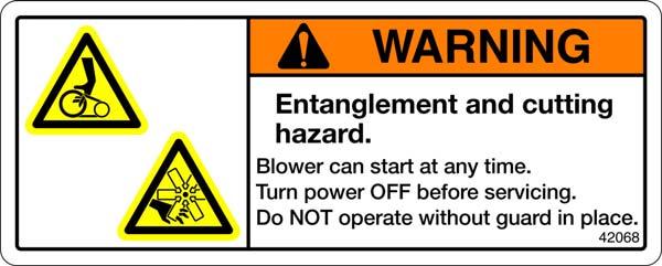
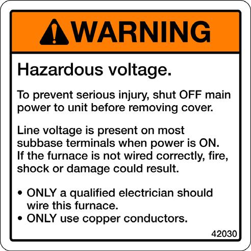
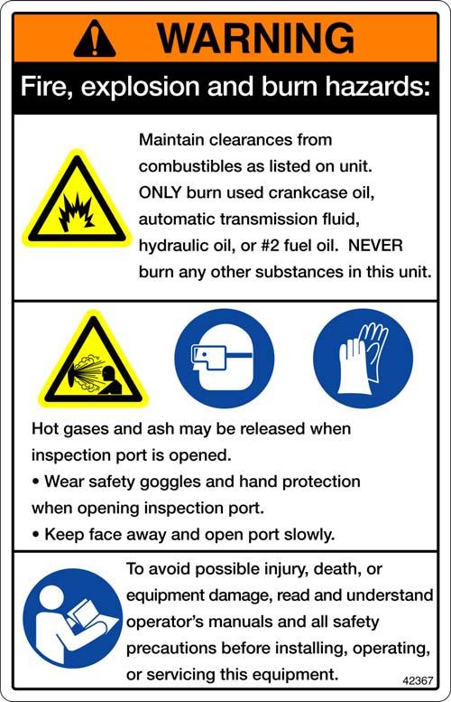
14 For Your Safety... (continued) Safety Labels Following are the locations and descriptions of all labels on your furnace cabinet. The following illustrations show the location of ALL labels on your furnace. Please note that some labels denote model number, model description, etc. while others contain important safety messages. Each Safety Label contains an important safety message starting with a key word as discussed earlier in this section (e.g. ATTENTION, CAUTION, WARNING, DANGER). For your safety and the safe operation of your furnace, review all labels and heed all safety messages as printed on the labels. If any labels on your Clean Burn furnace ever become worn, lost or painted over, please call your Clean Burn dealer for free replacements AIR OIL Furnace Cabinet Labels I88793 B Label Part # Description Furnace Electrical Shock Hazard Warning Label (several locations) Furnace Burn Hazard/Hazardous Voltage Warning Label UL Data Label UL Header Label - CB UL Header Label - CB UL Header Label - CB Made in USA / Pat Pending Combination Label Model CB-1750 Label Model CB-2501 Label Model CB-3250 Label Furnace Safety Warning Label (Multiple Messages - Fire/Shock/Burn Hazards) Furnace Blower/Fan Entanglement Hazard Warning Label (near blower) 1-6

15 For Your Safety... (continued) Furnace Cabinet Safety Labels 1-7
16 For Your Safety... (continued) Furnace Cabinet Safety Labels CB 1750 CB , UL ULC ATOM AIR PRESSURE OIL UL ULC ATOM AIR PRESSURE OIL ATF N/A ATF N/A BLOWER 2 24 DISCHARGE 60 POWER HZ POWER HZ 3/ / / / / / / / / TOTAL CIRCUIT AMPACITY MAXIMUM FUSE SIZE FOR COMMERCIAL OR INDUSTRIAL USE ONLY
17 For Your Safety... (continued) Furnace Cabinet Safety Labels CB UL ULC ATOM AIR PRESSURE OIL ATF 2.1 N/A BLOWER POWER HZ 2 120/ / / / / / TOTAL CIRCUIT AMPACITY 23 / 17.8 MAXIMUM FUSE SIZE (WITH OPTIONS) 30 / 20 FOR COMMERCIAL OR INDUSTRIAL USE ONLY LEOLA, PENNSYLVANNIA (USA) MH15393 USED OIL BURNING APPLIANCE USED OIL FIRED FURNACE USED OIL FIRED BOILER For use with Integral Primary Safety Control NO MULTI OIL HEATING SYSTEM FOR COMMERCIAL OR INDUSTRIAL USE ONLY. CERTIFIED TO ELECTRICAL AND FUEL BURNING REQUIREMENTS ONLY
 CB-525-S2 Burner Labels Label Part # Description 42005 Sold and Serviced By")
 42235 Burner Safety Warning")

18 For Your Safety... (continued) CB-525-S2 Burner Labels Label Part # Description Sold and Serviced By Label Burner Safety Warning Label (High Voltage/Moving Parts Hazards) Burner Safety Warning Label (Fire/Explosion Hazard - Reset Button) Burner Safety Warning Label (Fire/Explosion Hazard - Burner Installation and Service) Burner Model/Serial Number Label Logo/Burner Description Label Burner Power Label Made in USA / Pat Pending Combination Label (on side) CB-525-S2 BurnerSafety Labels I88603 B 1-10
19 SECTION 2: UNPACKING Before assembling your furnace, you must accomplish the following activities described in this section: Removing the Shipping Crate Unpacking and Inspecting All Components Warranty Registration Removing the Shipping Crate NOTE: Remove the shipping crate prior to assembly and installation of the furnace. DO NOT use the crate as a platform for furnace installation! 1. Carefully remove the top boards of the shipping crate. Then remove the front, back, and side panels of the shipping crate. 2. Carefully lift the furnace off the shipping pallet with a fork lift. ATTENTION: DO NOT attempt to slide the furnace cabinet out of the shipping crate--you may damage the furnace cabinet. Unpacking and Inspecting All Components Following is an itemized list of all components you should have received in your Clean Burn furnace shipment. Open all shipping containers and inspect all components according to the list. Immediately notify the freight company and your Clean Burn dealer in case of shipping damage or shortage(s). Keep all components together so you will have them as needed for furnace assembly and installation. Furnace Component List ONE SKID containing: Furnace cabinet Items packed inside furnace cabinet (combustion chamber): NOTE: Please refer to the procedure on the following page to remove these items. Target Hot air discharge assembly components plus hardware Furnace Accessories (items below in one box): Canister Filter Vacuum Gauge Check Valve and Check Valve Screen Wall Thermostat Barometric Damper Connector Block Burner Oil Line and Air Line Components Assorted bolts/fittings for assembly/installation of furnace components Operator's Manual Literature Packet (includes Tank Safety Label) ITEMS PACKED IN INDIVIDUAL BOXES: Burner Blower Assembly Metering Pump (includes Suction Oil Line Fittings Package) NOTE: You may have received additional boxes or skids if you ordered optional accessories. 2-1
20 Unpacking Items Packed Inside the Furnace To unpack the items packed inside the furnace cabinet (in the combustion chamber), you will need to open the combustion chamber door. 1. Remove the four nuts and washers which hold the combustion chamber door closed. Set the nuts and washers aside in a safe place for later re-installation after the target has been installed (Section 3). 2. Carefully swing the combustion chamber door open. Remove and inspect the components packed inside. 3. Leave the door unfastened (open) for assembly/installation procedures to be accomplished in the next section. CLEAN OUT DOOR COMBUSTION CHAMBER I88436 Figure 2A - Accessing the Combustion Chamber Warranty Registration For proper warranty registration, Clean Burn requires that you fill out the provided warranty registration card and return it within 30 days to: CLEAN BURN WARRANTY REGISTRATION Clean Burn, Inc. 34 Zimmerman Road Leola, Pennsylvania
21 Understanding Assembly SECTION 3: FURNACE ASSEMBLY Assembling your Clean Burn Furnace includes the following steps: (1) Installing the Blower Assembly (2) Installing the Hot Air Discharge Components (3) Installing the Energy Retention Disc (4) Installing the Burner (5) Installing the Connector Block, Oil Line Tubing, and Air Line Tubing Clean Burn recommends that you review all assembly procedures before proceeding, paying careful attention to safety information statements. Figure 3A on the following page provides a general overview of the furnace components and their proper assembly. Required Tools and Materials The following tools are required for furnace assembly and should be gathered before starting any procedures: 9/16" open-end wrench Medium flat-blade screwdriver Medium adjustable wrench 1/4" nut driver attachment for drill Variable speed drill 3-1
22 AIR OIL Operator's Manual: Models CB-1750, CB-2501 & CB-3250 "ALL THREAD" RODS COUPLINGS FOR "ALL THREAD" RODS JUNCTION BOX BURNER CABLE 4 BURNER MOUNTING BRACKET THROAT R.H. FURNACE BREECH 4 FURNACE DOOR 5 LH FURNACE BREECH WITH CLEAN OUT 1 NOTE: LOOP ON ENERGY RETENTION DISC HOOKS OVER MOUNTING BRACKET ON BACK WALL OF COMBUSTION CHAMBER 3 ENERGY RETENTION DISC INSTALLED ON BACK WALL OF COMBUSTION CHAMBER 2 HOT AIR DISCHARGE FURNACE BREECH NOTICE THE VARIOUS MOUNTING CHOICES FOR THE LOUVERS IT IS OK TO OPEN OR RESTRICT THE LOUVERS AS NEEDED, AND THEN TO TURN THOSE CONFIGURATIONS IN ANY OF FOUR DIRECTIONS I88437 B Complete assembly of the furnace according to the following list of activities as illustrated above: (1) Installing the Blower Assembly (2) Installing the Hot Air Discharge Components (3) Installing the Target (4) Installing the Burner (5) Installing the Connector Block, Oil Line Tubing, and Air Line Tubing NOTE: Corresponding procedures provided in order in this section. Figure 3A - Overview of Furnace Assembly 3-2
23 Installing the CB-1750 and CB-2501 Blower Assembly 1. Refer to Figures 3B and 3C. 2. Remove the blower stabilizer brackets as shown in Figure 3B. (These braces, which are installed at the factory, are designed to keep the blower in proper position during shipping. Note that these braces are provided on CB-2501 blower assemblies ONLY; CB-1750 blower assemblies do not require these special shipping braces.) 3. Position the blower over the opening in the back of the furnace cabinet by sliding the blower into the mounting angle brackets. Note that the mounting brackets may be loosened for adjustment, as needed. The blower should be centered over the opening. 4. Fasten the blower to the brackets with self-tapping screws (provided). Drive the screws into the blower housing through the holes in the mounting angle brackets. There are four holes along each side and across the top of the bracket to fasten the blower to the furnace cabinet. 5. Install the blower safety guards as shown. WARNING: To avoid serious personal injury, be sure to install both pieces of the blower guard around the blower prior to operating the furnace. NEVER operate the furnace without all safety shields/guards in place! ATTENTION: The air flow is changed when the guards are not in place which may result in damage to the blower motor. NOTE: For proper air flow through the furnace cabinet the blower must be positioned so that the bulge on the blower faces down as illustrated in Figures 3A, 3B, and 3C REMOVE SHIPPING BRACES ATTACH BLOWER TO FURNACE X 2 I88691 D Figure 3B - Installing the Blower Assembly (CB-1750 and CB-2501) 3-3
24 Installing the CB-1750 and CB-2501 Blower Assembly (continued) Note capacitor location on blower. CB-1750 is shown; CB-2500 capacitor is mounted on the opposite side of the blower. Figure 3C - Blower Installed on Furnace Cabinet (CB-1750 and CB-2501) Wiring the CB-1750 and CB-2501 Blower Motor WARNING: Make sure the main power to the furnace is turned OFF before wiring the blower motor. NOTE: Wiring schematics are provided in Figure 3E and Appendix B at the back of the manual. 1. After the blower has been secured to the back of the furnace cabinet, install the electrical conduit with the blower motor leads into the 4" x 6" rear junction box on the top of the furnace cabinet as shown in Figure 3C. 2. For CB-1750 furnaces (see Figure 3D): Connect the power lead coming from the blower assembly to the 4" x 6" electrical box mounted on the rear of the furnace cabinet. Connect the black (power) motor lead wire to the connector block terminal with the black (power) wire from the front electrical box. Connect the white (neutral) motor lead wire to the connector block terminal with the white (neutral) wire from the front electrical box. 3. For CB-2501 furnaces (see Figure 3E): Connect the power lead coming from the blower assembly to the 4" x 6" electrical box mounted on the rear of the furnace cabinet. Connect the black (power) motor lead wire to the T1 terminal of the contactor. Connect the white (neutral) motor lead wire to the T2 terminal of the contactor. 3-4 I88438 D
25 Installing the CB-1750 and CB-2501 Blower Assembly (continued) WHITE BLK WHITE BLACK REAR JUNCTION BOX BLACK WHITE Ref POWER IN (FLEX CONDUIT) Figure 3D - Detail of Blower Motor Wiring for CB-1750 WHITE SPADE (MALE TO FEMALE) REAR JUNCTION BOX WHITE WHT IN FLEX (UNDER LUG SCREW) BLACK (UNDER LUG SCREW) L 2 L1 T2 T1 BLK ORANGE Ref Figure 3E - Detail of Blower Motor Wiring for CB
26 Installing the CB-3250 Blower Assembly Mounting the CB-3250 Blower 1. Refer to Figures 3F and 3G. 2. Position the blower over the opening in the back of the furnace cabinet by sliding the blower into the mounting angle brackets. The top of the blower is slid over the lip on the back of the furnace. The mounting screws on top will go through the blower and anchor into the thicker lip pretruding from the back of the furnace cabinet. Check for proper positioning by referring to Figure 3G. 3. Fasten the blower to the brackets with self-tapping screws (provided). NOTE: There are three holes for fastening the blower along each side of the bracket, as well as three across the top. Installing the CB-3250 Motor on the Blower 1. Refer to Figures 3F and 3G. 2. Use self-tapping bolts to install the motor mounting bracket on the blower according to the dimensions provided in Figure 3F. 3. Slide the two (2) square-head bolts upside-down in the channel of the motor mounting bracket. 4. Install the motor mounting plate on the mounting bracket using the two bolts in the channel to hold the plate in position. DO NOT install the nuts on the bolts yet. Make sure the plate is flush with the side of the blower. 5. Use a self-tapping bolt to install the motor tensioning bracket on the blower according to the dimensions provided in Figure 3F. 6. Lift up on the end of the motor mounting plate until the hole in the side of the plate is aligned with the slot in the motor tensioning bracket. Push a bolt through the slot and install a nut loosely just to hold the plate in position. DO NOT tighten the nut yet. 7. Lift the motor into position on the motor mounting plate using the two bolts in the channel to hold the motor in place. Now loosely install the nuts on the two (2) bolts. 8. Slide the motor into position so the face of the motor is flush with the side of the blower. Now tighten the nuts. 9. Install the additional two (2) bolts and nuts through the upper holes in the motor mounting plate and motor. Tighten the nuts to hold the motor firmly in position. Wiring the CB-3250 Blower Motor WARNING: Make sure the main power to the furnace is turned OFF before wiring the blower motor. NOTE: Wiring schematics are provided in Figure H and Appendix B at the back of the manual. 1. After the blower has been secured to the back of the furnace cabinet, screw the electrical conduit with the blower motor leads into the motor housing. 2. Determine the voltage being supplied to the unit. Follow the correct wiring diagram in Figure H for either 115 Volts or 230 Volts. Connect the wire ends with the terminals to the motor. Refer to the wiring diagram on the motor to ensure that the motor is wired for proper voltage and CW rotation facing the shaft. 3. Install the electrical conduit with the blower motor leads into the 4" x 6" rear junction box on top of the furnace cabinet as shown in Figure 3G. Refer to Figure 3H for the proper wiring diagram. 3-6
27 8 (4) BLOWER ASSEMBLY PARTS LIST 1 NUT 2 MOTOR 3 MOTOR PULLEY 4 SHEAVE BUSHING 7/8" 5 MOTOR MOUNTING PLATE 6 BOLT 7 SQUARE HEAD BOLT 8 BLOWER GUARD 9 MOTOR MOUNTING BRACKET 10 BLOWER 11 MOTOR TENSIONING BRACKET 12 SELF TAPPING SCREW 13 BLOWER PULLEY 14 SHEAVE BUSHING 1" 15 BELT 16 BELT GUARD /4" 3/4" CB 3250 BLOWER DETAIL OF BRACKET INSTALLATION NOTE: The brackets must be installed at the correct position on the side of the blower as shown here to allow the belt guard to mount properly. 4" 8 1/2" I89022 Figure 3F - Blower Assembly Parts Detail (CB-3250) 3-7
28 Installing the CB-3250 Blower Assembly (continued) I89021 Figure 3G - Blower Installed on Furnace Cabinet (CB-3250) Installing the CB-3250 Motor Pulley, Blower Pulley, and V-Belt 1. Review the contents of the Blower Pulley and Motor Pulley as shown in Figure 3F. 2 Refer to Figure 3F. Place the blower pulley over and onto the blower shaft as far as possible with large bore end of taper outward. 3. Insert the blower key into the bushing. (If the key is deformed and does not fit into place, file the key to the proper size or replace it with a new key). 4. Slide the bushing (with key inserted) onto the shaft so the tapered end will engage into the pulley. NOTE: If bushing does not slide freely on shaft, wedge a screwdriver blade into the saw cut at the flange OD to open the bore of the bushing. CAUTION: Excessive force may split the bushing. 5. Align drilled holes in bushing flange with tapped holes in the pulley. Use the capscrews and washers provided with the bushing package to fasten the pulley on to the bushing. DO NOT COMPLETELY TIGHTEN THE SCREWS AT THIS POINT! Make sure you can still slide the bushing and pulley for future alignment with the motor pulley. (Additional information is available in the Bushing Instruction Sheet provided with each bushing) 6. Install the motor pulley following steps 1 through
29 GROUND VOLTS IN COMMON / NEUTRAL HOT LEG FLEX CONDUIT WHITE BLACK L 1 L 2 T 1 T 2 GREEN ORANGE CONTACTOR HAS A VOLT AC COIL CONNECT 2 HP BLOWER MOTOR ACCORDING TO THE LABEL SUPPLIED WITH THE MOTOR FOR CW ROTATION FACING THE SHAFT AND 115 VOLTS GROUND VOLTS IN HOT LEG HOT LEG COMMON / NEUTRAL FLEX CONDUIT WHITE BLACK L1 L 2 T1 T2 GREEN ORANGE CONTACTOR HAS A VOLT AC COIL CONNECT 2 HP BLOWER MOTOR ACCORDING TO THE LABEL SUPPLIED WITH THE MOTOR FOR CW ROTATION FACING THE SHAFT AND 230 VOLTS I89031 Figure 3H - Detail of Blower Motor Wiring for CB
30 Installing the CB-3250 Motor Pulley, Blower Pulley, and V-Belt (continued) 7. Align the motor pulley with the blower pulley. a. Place the blower bushing ½ inch from the end of the shaft and tighten the capscrews securely (9 Ft. - Lbs. if using a torque wrench). b. Place a level or straight edge flat onto the two most outer edges of the blower pulley. c. Place the motor pulley and bushing about ¼ inch away from the straight edge. d. Start tightening the screws on the motor bushing. As the screws are tightened, the motor pulley will approach the straight edge. TIGHTEN THE CAPSCREWS SECURELY (9 Ft. - Lbs. if using a torque wrench). e. Four points of the two pulleys should be touching the straight edge. If they don t make full contact, loosen the screws on the motor bushing and realign it so both pulleys are on the same plane. 8. Place the belt on the pulleys, starting with the motor pulley and feeding it onto the blower pulley. 9. Tighten the belt (Refer to Figure 3G). a. Raise the motor bracket and at the same time tighten the nut on the tension bracket. b. DO NOT over tighten the belt. Leave about 1inch of slack (when pushing on the top of the belt, it should deflect about 1 inch). Installing the CB-3250 Belt Guard and Blower Guard WARNING: To prevent serious personal injury, DO NOT operate the furnace without the belt and blower guards in place. 1. Refer to Figure 3F and 3G. 2. Install the belt guard and blower guard as shown. Determining the Air Discharge Configuration Before proceeding with the assembly of your furnace, it is important to determine the configuration of the air discharge for your furnace. There are three configurations to consider: (1) Unit Heater Furnace with blower assembly for free air applications. Follow the instructions (provided in this section) to install the blower assembly and air discharge components. Be sure to adhere to the proper specified clearances for Unit Heater Configurations as stated in Section 4 of this manual. (2) Central Furnace (A) Furnace with blower assembly for ducting applications with.25 or less static pressure.* Follow the instructions to install the blower assembly and air discharge components, and refer to the following chart for the proper air discharge and ducting specifications. Be sure to adhere to the proper specified clearances for Central Furnace Configurations as stated in Section 4 of this manual. (3) Central Furnace (B) Furnace with blower assembly for ducting applications from.25 to.40 static pressure.* Follow the instructions to install the blower assembly, and refer to the following chart for the proper air discharge and ducting specifications. Be sure to adhere to the proper specified clearances for Central Furnace Configurations as stated in Section 4 of this manual. 3-10
31 Determining the Air Discharge Configuration (continued) Static Pressure (SP) and Air Flow (CFM) Specifications CB-1750 Air Discharge Louvers Mounted on Furnace Air Discharge Louvers Mounted on Furnace (Fully Open - Ductwork Installed Over Top)* Air Discharge Louvers Removed Ductwork Installed on Furnace Free Air** 0.25 Inches of W.C.** 0.30 Inches of W.C.** 1625 CFM 1500 CFM 1400 CFM CB-2501 Air Discharge Louvers Mounted on Furnace Air Discharge Louvers Mounted on Furnace (Fully Open - Ductwork Installed Over Top)* Air Discharge Louvers Removed Ductwork Installed on Furnace Free Air** 0.25 Inches of W.C.** 0.40 Inches of W.C.** 2700 CFM 2500 CFM 2400 CFM CB-3250 Air Discharge Louvers Mounted on Furnace Air Discharge Louvers Removed Ductwork Installed on Furnace Air Discharge Louvers Removed Ductwork Installed on Furnace Free Air** 0.25 Inches of W.C.** 0.40 Inches of W.C.** 3300 CFM 3150 CFM 2900 CFM *NOTE: The open louvers function as an orifice plate for the lower static pressure installations. **ATTENTION: A qualified electrician must check the blower motor amperage during operation of the furnace to ensure that motor amperage does not exceed 85% of the maximum amperage on the motor label. DO NOT operate the blower motor above 85% of maximum amperage or motor damage may occur. IMPORTANT NOTE: It is essential that qualified HVAC personnel properly design the ductwork for your furnace and determine the static pressure for your ducting application. Note that existing ductwork at your installation site may not be appropriate or meet the specifications for this furnace installation. For static pressure readings as shown in the chart above, the ductwork should be installed directly over the opening in the SIDE of the furnace cabinet (i.e. where the louver panels would be installed for free air applications.) For Central Furnace applications, ductwork may NOT be installed over the bottom opening. 3-11
32 Installing the Hot Air Discharge Components It is very important to properly install the hot air discharge components (louvers and blank cover panels) to direct the flow of air from the furnace. As you will note from Figures 3I and 3J, the air discharge panels are to be installed on the side(s) and/or bottom of the furnace. The air flow may be directed down, front, or back, depending upon how the louvers and cover panels are installed. IMPORTANT NOTE FOR CENTRAL FURNACE APPLICATIONS: For ducting applications of.25 static pressure, install the louvers as described in the following procedure, and then install the ductwork over top of the fully open louvers. For ducting applications of.30 (CB-1750) or.40 (CB-2501 and CB-3250) static pressure, DO NOT install the louvers. The ductwork should be installed directly over the desired air discharge openings on the side of the furnace cabinet. Ductwork must be installed over side opening(s) ONLY. Ductwork may NOT be installed over the bottom air discharge opening. 1. Refer to Figures 3I and 3J. Determine the desired air flow discharge pattern. Note that each furnace is supplied with (2) louver sections and (4) blank cover panels. Air discharge openings are: (1) on each side of the furnace, and (1) on the bottom of the furnace. 2. Install the louver panels in the desired location(s) with the self-tapping screws provided. Holes are pre-drilled in the furnace cabinet to accommodate installation of the panels. Air Flow Discharge Installation Guidelines: When determining the placement of the air discharge louvers, you also need to consider the required clearances from combustibles as stated in Section 4 of this manual. Note that each furnace model supplied with (2) louver sections which may be installed together on one side or the bottom as shown here OR the louvers may be split for partial air discharge on each side and/or bottom as shown in Figure 3J. NOTE: Bottom louver installation applies to Unit Heater furnaces ONLY. Ductwork for Central Furnace applications may NOT be installed over the bottom opening. I88439 B Figure 3I - Hot Air Discharge Components (Louvers/Blank Covers) Installed on Furnace 3-12
33 Installing the Hot Air Discharge Components (continued) 3. Adjust the louvers for the desired air flow direction. ATTENTION: DO NOT restrict the flow of the hot air from the furnace by closing the louvers, or the furnace will not operate properly. 4. Install the blank covers over the remaining air discharge opening(s) on the furnace cabinet. Louvers split between two side openings, showing left and right side views of same furnace NOTE: When louver panels are "split" between two sides, make sure the louvers are installed in the upper half of each side air discharge opening as shown here. Louvers split between left side and bottom openings, showing left and right side views of same furnace NOTE: When louver panels are "split" between a side and the bottom, make sure the bottom louvers are installed in the forward half of the bottom air discharge opening as shown here. Louvers split between right side and bottom openings, showing left and right side views of same furnace Figure 3J - Sample Split Louver Installations for Partial Air Discharge on Sides and/or Bottom 3-13 I88537 A
34 Installing the Energy Retention Disc Installing the Energy Retention Disc at the Back of the Combustion Chamber ATTENTION: DO NOT fire your furnace without the Energy Retention Disc in place, or combustion chamber damage will occur. Handle the Energy Retention Disc carefully to avoid damaging it. 1. Refer to Figure 3A to review the proper positioning of the Energy Retention Disc. 2. Swing open the clean-out door on the front of the furnace to gain access to the combustion chamber. 3. Use a long rod to support the Energy Retention Disc as you guide it into position on the back of the combustion chamber. The loop on the back of the Energy Retention Disc fits over the hook located on the back of the combustion chamber. Closing the Furnace Door 1. After the Energy Retention Disc has been installed, close the furnace clean-out door. 2. Tighten the four (4) lock-down nuts in a criss-cross pattern until all are snug. 3-14
35 Installing the Burner Checking the Burner Nozzle and Electrodes NOTE: The burner nozzle is factory installed. All furnace models (CB-1750, CB-2501, and CB-3250) use a Delavan 9-5 nozzle. The nozzle size is indicated on the nozzle as shown in Figure 3K. Refer also to Appendix A at the back of the manual for additional specifications/instructions on the burner nozzle. ATTENTION: Check the electrode settings as specified in Figure 3K. The electrode settings must be correct for your burner to operate properly. BURNER NOZZLE NOZZLE IS STAMPED EITHER 9 5 OR 5 ON FLAT OF NOZZLE HEAD SIDE VIEW AA 3/16" GAP BETWEEN ELECTRODES & NOZZLE 3X CRITICAL DIMENSION: NOZZLE MUST BE 1/8" AHEAD OF THE DISK. NOZZLE MUST NOT BE BEHIND THE DISK. VIEW BB VIEW AA 1/8" SPARK GAP SIDE VIEW BB I88647 Figure 3K - Burner Nozzle and Electrode Specifications 3-15
36 Installing the Burner (continued) Mounting the Burner on the Hinge Bracket ATTENTION: Burner tube components (e.g. electrodes and retention head) are factory set. Handle the burner with extreme care so that burner components are not damaged. 1. Remove the nut from the mounting flange of the furnace cabinet, and set it aside for later use. 2. Lift the burner into position so that it is mounted on the hinge bracket on the furnace cabinet. 3. Carefully swing the burner so the retention head enters the throat of the furnace. 4. Check the clearance between the retention head and the furnace throat. There must be at least 1/8" clearance, so the retention head is not "bumped" as you swing the burner into firing position. NOTE: If the retention head "bumps" the furnace throat, adjust the hinge bracket bolts as follows: While supporting the burner, slightly loosen the two (2) hinge bracket bolts. Carefully re-position the burner so it swings freely into its firing position. With the burner in its firing position, re-tighten the hinge bracket bolts. 3-16
37 Installing the Connector Block, Oil Line Tubing, and Air Line Tubing ATTENTION: DO NOT use teflon tape on any fittings. Teflon tape residues will plug vital burner components and void your warranty. Installing the Connector Block on the Furnace Door 1. Refer to Figure 3L. 2. Use the two (2) bolts to install the aluminum connector block onto the furnace cabinet. 3. Remove and discard the red caps and plugs from the fittings and ports on the connector block. DO NOT allow any dirt/debris to enter these components during furnace assembly. ATTENTION: The connector block includes an accumulator. The accumulator functions like a shock absorber on the oil line to prevent pressure buildup and protect vital burner components. It is important that the connector block is installed as shown so that the accumulator is in a vertical position to prevent sediment from settling in the accumulator. Never operate your furnace without the connector block and accumulator properly installed on the furnace, or damage may occur to vital burner components. OIL FITTING ON BURNER CONNECTOR BLOCK FRONT VIEW OF FURNACE OIL LINE AIR OIL LINE FITTING ON BURNER LINED UP WITH OIL LINE OIL LINE OIL Installing the Oil Line Tubing ATTENTION: DO NOT disassemble the compression fitting from the swivel fitting. To prevent leaks, the NPT threads of the compression fitting have been sealed with hydraulic sealant during assembly of the fittings at the factory. 1. Remove and discard the red caps from the oil line tubing. 2. Loosely install the oil line tubing into the oil line fitting on the burner. SWIVEL ASSEMBLY CONNECTOR BLOCK SIDE VIEW OF FURNACE SHOWING OIL LINE INSTALLED I88341 A Figure 3L - Installation of Connector Block and Oil Line 3. Use a wrench to slightly rotate the oil line fitting on the burner counterclockwise so the tubing lines up with the swivel assembly. Slightly bend the tubing as shown in Figure 3L, if required, to "line up" the oil line. 4. If necessary, use a tubing cutter to cut the tubing to the proper length. ATTENTION: Due to adjustment of the burner hinge bracket, the oil line tubing may need to be cut to fit properly. DO NOT lift up on the burner when installing the oil line tubing to compensate for oil line tubing that is too long. This will place the weight of the burner on the swivel fitting and result in leaks at the swivel fitting seal. 3-17
OPERATOR'S MANUAL CLEAN BURN MULTI-OIL FURNACE MODELS: CB-3500 with CB-525-S2 BURNER CB-5000 with CB-550-S2 BURNER
 OPERATOR'S MANUAL CLEAN BURN MULTI-OIL FURNACE MODELS: CB-3500 with CB-525-S2 BURNER CB-5000 with CB-550-S2 BURNER U.L. Listed Used Oil Burning Appliance #MH15393 (N) U.L.-C Listed #CMP217 I88798 C PUBLICATION
OPERATOR'S MANUAL CLEAN BURN MODELS: CB-1750, CB-2500, and CB-3250 MULTI-OIL FURNACES with CB-525-S2 BURNER
 OPERATOR'S MANUAL CLEAN BURN MODELS: CB-1750, CB-2500, and CB-3250 MULTI-OIL FURNACES with CB-525-S2 BURNER USED-OIL BURNING APPLIANCE ENERGY SYSTEMS www.cleanburn.com #MH15393 (N) FOR YOUR SAFETY - DO
OPERATOR'S MANUAL CLEAN BURN MULTI-OIL FURNACE MODELS: CB-3500 with CB-525-S2 BURNER CB-5000 with CB-550-S2 BURNER
 OPERATOR'S MANUAL CLEAN BURN MULTI-OIL FURNACE MODELS: CB-3500 with CB-525-S2 BURNER CB-5000 with CB-550-S2 BURNER USED-OIL BURNING APPLIANCE #MH15393 (N) ENERGY SYSTEMS www.cleanburn.com I88798-C LISTED
OPERATOR'S MANUAL FURNACE MODEL: CB 140 MULTI-OIL FURNACES with CB-125 BURNER
 OPERATOR'S MANUAL FURNACE MODEL: CB 140 MULTI-OIL FURNACES with CB-125 BURNER USED-OIL BURNING APPLIANCE #MH15393 (N) I89053-A LISTED USED OIL-FIRED FURNACE PUBLICATION DATE: 07/16/13, Rev. 13 CLEAN BURN
OPERATOR'S MANUAL CLEAN BURN MULTI-OIL FURNACE MODELS: CB-3500 and CB-5000 with CB-500 Series BURNER
 OPERATOR'S MANUAL CLEAN BURN MULTI-OIL FURNACE MODELS: CB-3500 and CB-5000 with CB-500 Series BURNER 230 V / 50 Hz Danfoss Type BHO 64 Nr. 057H7036 220-240 50-6 0Hz 3W ts 10 s FOR YOUR SAFETY DO NOT STORE
OPERATOR'S MANUAL. FURNACE MODELS: SATURN 140 and SATURN 230 MULTI-OIL FURNACES with SATURN 125 BURNER
 OPERATOR'S MANUAL FURNACE MODELS: SATURN 140 and SATURN 230 MULTI-OIL FURNACES with SATURN 125 BURNER U.L. Listed Used Oil Burning Appliance #MH15393 (N) U.L.-C Listed #CMP217 PUBLICATION DATE: 6/13/11,
OPERATOR'S MANUAL. CLEAN BURN MODELS: CB-1500 and CB-2500 MULTI-OIL FURNACES with CB-500 Series Burner
 OPERATOR'S MANUAL CLEAN BURN MODELS: CB-1500 and CB-2500 MULTI-OIL FURNACES with CB-500 Series Burner 230 V / 50 Hz FOR YOUR SAFETY - DO NOT STORE GASOLINE OR OTHER FLAMMABLE VAPORS AND LIQUIDS IN THE
INSTALLER'S MANUAL CLEAN BURN TRANSPORT HEATER MODEL: 45 TH
 INSTALLER'S MANUAL CLEAN BURN TRANSPORT HEATER MODEL: 45 TH I89032 PUBLICATION DATE: 4/14/09, Rev. 1 CLEAN BURN PART # 43217 Copyright 2009 Clean Burn, Inc. All rights reserved. No part of this publication
OPERATOR'S MANUAL. PUBLICATION DATE: 1/7/08, Rev. 8 CLEAN BURN PART #43146
 OPERATOR'S MANUAL CLEAN BURN MODELS: CB-200-CTB COIL TUBE BOILER with CB-525-S2 Burner & Metering Pump CB-350-CTB COIL TUBE BOILER with CB-551-H3 Burner & Metering Pump CB-500-CTB COIL TUBE BOILER with
OPERATOR'S MANUAL. PUBLICATION DATE: 07/16/13, Rev. 13 CLEAN BURN PART #43146
 OPERATOR'S MANUAL CLEAN BURN MODELS: CB-200-CTB COIL TUBE BOILER with CB-525-S2 Burner & Metering Pump CB-350-CTB COIL TUBE BOILER with CB-551-H3 Burner & Metering Pump CB-500-CTB COIL TUBE BOILER with
OPERATOR'S MANUAL. CLEAN BURN COIL TUBE BOILER MODELS: CB-200-CTB and CB-350-CTB with CB-500 Series Burner & Metering Pump
 OPERATOR'S MANUAL CLEAN BURN COIL TUBE BOILER MODELS: CB-200-CTB and CB-350-CTB with CB-500 Series Burner & Metering Pump 230 V / 50 Hz I88729 A PUBLICATION DATE: 4/7/06, Rev. 4 CLEAN BURN PART #43186
TURBO Fiberglass Cone Fan and Grill Fan 48'' Belt Drive. Installation & Operator s Instruction Manual
 TURBO Fiberglass Cone Fan and Grill Fan 48'' Belt Drive Installation & Operator s Instruction Manual July 1998 MV1383B Chore-Time TURBO TM Fan Extended Warranty Chore-Time Equipment warrants new TURBO
READ AND SAVE THESE INSTRUCTIONS READ CAREFULLY BEFORE ATTEMPTING TO ASSEMBLE, INSTALL, OPERATE OR MAINTAIN THE PRODUCT DESCRIBED. PROTECT YOURSELF AN
 READ AND SAVE THESE INSTRUCTIONS READ CAREFULLY BEFORE ATTEMPTING TO ASSEMBLE, INSTALL, OPERATE OR MAINTAIN THE PRODUCT DESCRIBED. PROTECT YOURSELF AND OTHERS BY OBSERVING ALL SAFETY INFORMATION. FAILURE
DR-180 Through the Wall Exhaust Fan PRODUCT MANUAL & INSTALLATION GUIDE
 DR-180 Through the Exhaust Fan PRODUCT MANUAL & INSTALLATION GUIDE READ AND SAVE THESE INSTRUCTIONS READ CAREFULLY BEFORE ATTEMPTING TO ASSEMBLE, INSTALL, OPERATE OR MAINTAIN THE PRODUCT DESCRIBED. PROTECT
Air Storm Fans. Air Storm 54 Fiberglass Fan Installation and Operation Manual
 Air Storm 54 Fiberglass Fan Installation and Operation Manual Table of Contents GrowerSELECT General Page... 3 Safety... 4 Warning Labels... 4 Installation... 5 Operation Safety... 5 Maintenance Safety...
48 Vanguard Belt Drive Fans Installation and Operators Instruction Manual
 8 Vanguard Belt Drive Fans Installation and Operators Instruction Manual Thank You The employees of Chore-Time Equipment would like to thank your for your recent Chore-Time purchase. If a problem should
e Bath Fan with Light User s Guide
 e Bath Fan with Light User s Guide abfl50uq, BFL60UQ, BFL70, BFL85 Item Stock Number(s): BFL50UQ, BFL60UQ, BFL70, BFL85 IMPORTANT INSTRUCTIONS - OPERATING MANUAL READ AND SAVE THESE INSTRUCTIONS READ CAREFULLY
48 Vanguard Belt Drive Fans Installation and Operators Instruction Manual
 8 Vanguard Belt Drive Fans Installation and Operators Instruction Manual Thank You The employees of Chore-Time Equipment would like to thank your for your recent Chore-Time purchase. If a problem should
e Bath Fan with Light User s Guide
 e Bath Fan with Light User s Guide abfl100rnl, BFL125RNL Item Stock Number(s): BFL100RNL, BFL125RNL IMPORTANT INSTRUCTIONS - OPERATING MANUAL READ AND SAVE THESE INSTRUCTIONS READ CAREFULLY BEFORE ATTEMPTING
IMPORTANT INSTRUCTIONS - OPERATING MANUAL
 IMPORTANT INSTRUCTIONS - OPERATING MANUAL Models: AK80LSL, AK100LSL Exhaust Fan READ AND SAVE THESE INSTRUCTIONS READ CAREFULLY BEFORE ATTEMPTING TO ASSEMBLE, INSTALL, OPERATE OR MAINTAIN THE PRODUCT DESCRIBED.
e Bath Fan with Light User s Guide
 e Bath Fan with Light User s Guide abfl125rok Item Stock Number(s): BFL125ROK IMPORTANT INSTRUCTIONS - OPERATING MANUAL READ AND SAVE THESE INSTRUCTIONS READ CAREFULLY BEFORE ATTEMPTING TO ASSEMBLE, INSTALL,
Air Storm Fans. Air Storm 18 Fiberglass Fan Installation and Operation Manual
 Air Storm 18 Fiberglass Fan Installation and Operation Manual Table of Contents GrowerSELECT General Page...3 Safety...4 Warning Labels...4 Installation...5 Operation Safety...5 Maintenance Safety...5
User s Manual and Operating Instructions
 User s Manual and Operating Instructions Model Numbers: CL-30P-DDF, CL-20F-DDF, CL-24O-DDF, CL-30-DDF READ AND SAVE THESE INSTRUCTIONS IMPORTANT: Read and understand all of the directions in this manual
36 & 48 E-Z Cone Fan. Installation & Operator s Instruction Manual (Direct Drive)
") 36 & 48 E-Z Cone Fan Installation & Operator s Instruction Manual (Direct Drive) September 1997 MV1433C Chore-Time Warranty Chore-Time Equipment warrants each new product manufactured by it to be free
36 & 48 E-Z Cone Fan Installation & Operator s Instruction Manual (Direct Drive) September 1997 MV1433C Chore-Time Warranty Chore-Time Equipment warrants each new product manufactured by it to be free
Air Storm Fans. Air Storm 24 Fiberglass Fan Installation and Operation Manual
 Air Storm 24 Fiberglass Fan Installation and Operation Manual Hog Slat Inc. Newton Grove, NC USA May 2015 Table of Contents GrowerSELECT General Page...3 Safety...4 Warning Labels...4 Installation...5
THE BARCLAY HUGGER CEILING FAN INSTALLATION INSTRUCTIONS
 THE BARCLAY HUGGER CEILING FAN INSTALLATION INSTRUCTIONS Please read and save these instructions These instructions are to be used in the installation of the following QUORUM INTERNATIONAL fans... The
INSTALLATION INSTRUCTIONS
 INSTALLATION INSTRUCTIONS Keep these instructions with the boiler at all times. BOYERTOWN FURNACE CO. PO Box 100 BOYERTOWN, PA 19512 1-610-369-1450 www.boyertownfurnace.com 5-25-12 2 Danger Warning Caution
INSTALLATION INSTRUCTIONS Trade-Wind In-Line Blower / Ventilators
 INSTALLATION INSTRUCTIONS Trade-Wind In-Line Blower / Ventilators Models: PSX006XL PSD008XL PSD010XL CONTENTS: Part 1 - Planning The Installation Part 2 - Securing The Blower / Ventilator Part 3 - Electrical
e Heater/Exhaust Fan/Light User s Guide
 e Heater/Exhaust Fan/Light User s Guide abflh70l, BFLH85L Item Stock Number(s): BFLH70L, BFLH85L IMPORTANT INSTRUCTIONS - OPERATING MANUAL READ AND SAVE THESE INSTRUCTIONS READ CAREFULLY BEFORE ATTEMPTING
MODEL HS115-3, HS115-4 & HS115-5 WIRING DIAGRAM ADDENDUM
 TJERNLUND PRODUCTS, INC. 1601 Ninth Street White Bear Lake, MN 55110-6794 PHONE (800) 255-4208 (651) 426-2993 FAX (651) 426-9547 Visit our web site www.tjernlund.com MODEL HS115-3, HS115-4 & HS115-5 WIRING
ST. KITTS CEILING FAN
 ITEM #0845047 ST. KITTS CEILING FAN MODEL #40829 Questions, problems or missing parts? Before returning this item to your retailer, call our customer service department at 1-800-643-0067, Monday - Thursday,
MODEL CDB8 INSTALLATION INSTRUCTIONS
 REV 0417 TJERNLUND PRODUCTS, INC. 1601 Ninth Street White Bear Lake, MN 55110-6794 PHONE (800) 255-4208 (651) 426-2993 FAX (651) 426-9547 Visit our web site www.tjernlund.com SUITABLE FOR SIDE WALL OR
FES - Series Portable Electric Heaters. YES - Series Suspended Electric Heaters CONTENTS
 FOSTORIA INDUSTRIES, INC. A DIVISION OF FES - Series Portable Electric Heaters YES - Series Suspended Electric Heaters (FES-1524-3E shown) IMPORTANT SAFETY INFORMATION INSIDE Serious injury or death possible.
VENTILATION FAN WITH LED LIGHT AND HEATER MODEL RAD110LED
 VENTILATION FAN WITH LED LIGHT AND HEATER MODEL RAD110LED TABLE OF CONTENTS Package Contents Important Instructions Preparation Assembly Instructions Wiring Instructions Operating Instructions Care and
MAYFIELD CEILING FAN LISTED E ITEM # MODEL #BTH44ABZC5C BTH44BNK5C Español p. 20 ATTACH YOUR RECEIPT HERE.
 Harbor Breeze is a registered trademark of LF, LLC. All Rights Reserved. ITEM #0331094 0331096 MAYFIELD CEILING FAN MODEL #BTH44ABZC5C BTH44BNK5C Español p. 20 ATTACH YOUR RECEIPT HERE Serial Number Purchase
FOR EASY, FAST INSTALLATION AND FOR RESULTS
 Page 1 INSTALLATION & OPERATING INSTRUCTIONS FOR FEDERAL FLOOR FURNACE OFB-100 AND OFB100L UNPACK SHIPMENT CAREFULLY AND INSPECT FOR DAMAGE. ALL GOODS ARE CAREFULLY MANUFACTURED, INSPECTED, CHECKED, AND
Operating Instructions & Parts Manual. Silent Low-Profile Ceiling Fans. Models 3DPE2A, 3DPE3A, 1UBH6B, 1UBH7B, 1UBH8A, 5AE68B, 5AE69A
 Operating Instructions & Parts Manual EN Silent Low-Profile Ceiling Fans Models 3DPE2A, 3DPE3A, 1UBH6B, 1UBH7B, 1UBH8A, 5AE68B, 5AE69A 465933 PLEASE READ AND SAVE THESE INSTRUCTIONS. READ CAREFULLY BEFORE
User s Manual and Operating Instructions
 User s Manual and Operating Instructions Model Numbers: PT-18W-DDF-A, PT-20F-DDF-A, PT-20S-DDF, PT-24O-DDF, PT-24-DDF, PT-24-DDF-F, PT-30-DDF, PT-30P-DDF-A, PT-30P-DDF-AF READ AND SAVE THESE INSTRUCTIONS
INSTALLATION INSTRUCTIONS & USE & CARE GUIDE Euro-style Range Hood ESH5200
 INSTALLATION INSTRUCTIONS & USE & CARE GUIDE Euro-style Range Hood ESH5200 Installer: Owner: READ AND SAVE THESE INSTRUCTIONS Please leave Installation Instructions with the range hood. Please keep Installation
TILGHMAN CEILING FAN. LISTED For Damp Location E ITEM # MODEL #WCK52LMW5N WCK52NWZ5N. Español p. 20 ATTACH YOUR RECEIPT HERE
 ITEM #0294980 0294981 TILGHMAN CEILING FAN Harbor Breeze is a registered trademark of LF, LLC. All Rights Reserved. MODEL #WCK52LMW5N WCK52NWZ5N Español p. 20 ATTACH YOUR RECEIPT HERE Serial Number Purchase
Corn Flame Energy Corn Stove Model 3000
 Corn Flame Energy Corn Stove Model 3000 Installation and Operation Guide Read thoroughly before starting installation Save this manual for future reference SAFETY NOTICE If this stove is not properly installed,
INFRARED RADIANT HEATER RSCA SERIES CERAMIC HEATERS NATURAL GAS PROPANE GAS DATE: PROJECT: ARCHITECT/ENGINEER: CONTRACTOR: SUBMITTED BY:
 INFRARED RADIANT HEATER RSCA SERIES CERAMIC HEATERS NATURAL GAS (CHECK ONE) PROPANE GAS PROJECT: ARCHITECT/ENGINEER: NAME: ADDRESS: NAME: ADDRESS: DATE: CONTRACTOR: SUBMITTED BY: NAME: ADDRESS: EQUIPMENT
VENTILATION FAN READ AND SAVE THESE INSTRUCTIONS. MODEL Pro200/Pro300 TABLE OF CONTENTS. Package Contents. General Safety Information
 VENTILATION FAN MODEL Pro00/Pro300 TABLE OF CONTENTS Package Contents General Safety Information 3 Preparation and Wiring Diagrams 4 Assembly Instructions 5 Grille Installation 6 Operation 6 Care and Maintenance
Bathroom Exhaust Fan
 Bathroom Exhaust Fan Models: Installation and Operation Instructions Please read all instructions before installing and operating. All wiring and installation must be in accordance with CEC, NEC and local
TOUCHDOWN 48 CEILING FAN
 TOUCHDOWN 48 CEILING FAN MODEL #50205 Español p. 20 Questions, problems, missing parts? Before returning to your retailer, call our customer service department at 1-877-361-3883, Monday - Thursday, 8 am
FLCH4R Garage and Utility Electric Heater
 FLCH4R Garage and Utility Electric Heater Installation, Operation & Maintenance Instructions Model No. Volts Amps Watts BTU/HR Phase High Low High Low High Low Min Fuse Size* FLCH4R 208 17.3 8.66 3600
WMWLB / WMWFM / WTWLB / WTWFM Series Hydronic Heating Unit
 January 2008 WMWLB / WMWFM / WTWLB / WTWFM Series Hydronic Heating Unit Installation Operation Maintenance The units are designed for permanent up flow, counter flow, or horizontal left or right airflow
breeze easytm model # F100-1W
 DewStop breeze easytm model # F100-1W Installation Guide Read and Save These Instructions LISTED Questions, Problems, Missing Parts? Please Call 1-360-876-2974 or E-Mail info@dewstop.com please retain
INSTALLATION, OPERATION, AND MAINTENANCE MANUAL
 INSTALLATION, OPERATION, AND MAINTENANCE MANUAL TUBE AXIAL FANS BTA, WTA, HTA, DDA The purpose of this manual is to aid in the proper installation and operation of the fans. These instructions are intended
Mighty Venter Power Vent System
 Installation and Operation Instructions Document 7008B Installation and Operation Instructions for Mighty Venter Power Vent System Models MV2, MV3, MV4, and MV5 for Mighty Therm Sizes 500-1825 FOR YOUR
INSTALLATION GUIDE Dual Fuel Ranges
 INSTALLATION GUIDE Dual Fuel Ranges Contents Wolf Dual Fuel Ranges......................... 3 Safety Instructions............................ 4 Dual Fuel Range Specifications.................. 5 Dual Fuel
 INSTALLATION INSTRUCTIONS & USE & CARE GUIDE 01A/02A Series Models 01A/02A Series Models RANGE HOOD LOCATION 1. The range hood must be installed just above the cooktop. 2. The minimum distance from the
VENTILATION FAN. MFG Model : VFB80HLED2/VFB080C4L2 /VFB080C4LED2/ VFB100HLED2/VFB100C4LED1 READ AND SAVE THESE INSTRUCTIONS
 VENTILATION FAN MODEL 80HLED/80L/80LED/00HLED/00LED TABLE OF CONTENTS Package Contents General Safety Information 3 Preparation Assembly Instructions 5 New Construction 5 Existing Construction 6 Connect
ELECTRIC COOKTOP INSTALLATION INSTRUCTIONS
 INSTALLATION AND SERVICE MUST BE PERFORMED BY A QUALIFIED INSTALLER. IMPORTANT: SAVE FOR LOCAL ELECTRICAL INSPECTOR'S USE. READ AND SAVE THESE INSTRUCTIONS FOR FUTURE REFERENCE. U.S.A. WARNING FOR YOUR
RSIF power venter USA CAN READ AND SAVE THESE INSTRUCTIONS! Installation and operation manual. Product information Chapters 1 + 2
 3002239 RSIF 2014-04-04 Installation and operation manual RSIF power venter READ AND SAVE THESE INSTRUCTIONS! Product information Chapters 1 + 2 Mechanical installation Chapter 3 Electrical installation
ELSTON 52 CEILING FAN
 ELSTON 52 CEILING FAN MODEL #10290 Español p. 21 Questions, problems, missing parts? Before returning to your retailer, call our customer service department at 1-877-361-3883, Monday - Thursday, 8 am -
Service Parts, Kits and Accessories
 The parts identification guides on the following pages have been designed to give a quick reference to component parts used on pilot ignition agricultural building heaters. The guides identify components
Installation Electric Dryers Instructions 01
 Installation Electric Dryers Instructions 01 Questions? Call 800.GE.CARES (800.432.2737) or visit our Web site at: GEAppliances.com This is the safety alert symbol. This symbol alerts you to potential
INSTALLATION INSTRUCTIONS & USE & CARE GUIDE 06E Series Model 06E Series Model RANGE HOOD LOCATION 1. The range hood must be installed just above the
 INSTALLATION INSTRUCTIONS & USE & CARE GUIDE 06E Series Model 06E Series Model RANGE HOOD LOCATION 1. The range hood must be installed just above the cooktop. 2. The minimum distance from the cooking surface
Installation & Maintenance Instructions
 Portable High Temperature Blower Attention: Do not operate this heater in explosive areas. Installation & Maintenance Instructions Dear Owner, Congratulations! Thank you for purchasing this new heater
SUTTON 52 CEILING FAN
 SUTTON 52 CEILING FAN MODELS #50188, 50189, 50190 Español p. 19 Questions, problems, missing parts? Before returning to your retailer, call our customer service department at 1-877-361-3883, Monday - Thursday,
W Model 1RKU2 w/optional Wall mount. Unit Model Weight (Lbs) Kilowatts Volts- Phase Amps Fan Output Heat Output
 Kilowatts Volts- Phase Amps Fan Output Heat Output") Operating Instructions & Parts Manual 1RKT2, 1RKT3, 1RKT4, 1RKT5, 1RKT9 and 1RKU2 Please read and save these instructions. Read carefully before attempting to assemble, install, operate or maintain the
Operating Instructions & Parts Manual 1RKT2, 1RKT3, 1RKT4, 1RKT5, 1RKT9 and 1RKU2 Please read and save these instructions. Read carefully before attempting to assemble, install, operate or maintain the
Easy installation in both new construction and retrofit. ZB90C ZB110C X2 Multi-Speed Ventilation Fan INSTALLATION GUIDE
 READ AND SAVE THESE INSTRUCTIONS Installer: leave this guide with homeowner. Register your product online at www.broan.ca/register.asp. ZB90C ZB0C X Multi-Speed Ventilation Fan INSTALLATION GUIDE Easy
Quest Power Electric Heat EHS 31 Pro
 Quest DRY Power 150 Electric Heat EHS 31 Pro Read and Save These Instructions The Power Electric Heat EHS 31 Pro portable, heavy duty electric heater features a built-in 50-amp twist lock receptacle designed
User s Manual and Operating Instructions
 User s Manual and Operating Instructions Model Numbers: CL-36-BDF-A, CL-42-BDF-A, CL-48-BDF-A READ AND SAVE THESE INSTRUCTIONS IMPORTANT: Read and understand all of the directions in this manual before
The Extraordinaire OWNER S MANUAL. Orbital Ceiling Fan. Model No. OF110** READ AND SAVE THESE INSTRUCTIONS. Net Weight 14.5 lbs. or 6.59 kg.
 The Extraordinaire Orbital Fan WARNING: Support Directly From Building Structure Net Weight 14.5 lbs. or 6.59 kg. Model No. OF110** OWNER S MANUAL READ AND SAVE THESE INSTRUCTIONS Important Safety Instructions
Smart Choice Electric Dryer Installation Kit
 pn/ 5304501810 Smart Choice Electric Dryer Installation Kit BEFORE BEGINNING INSTALLATION, READ ALL MANUFACTURER S INSTALLATION INSTRUCTIONS THOROUGHLY DANGER FIRE AND ELECTROCUTION HAZARD YOU DO NOT POSSESS
SAN RAPHAEL PRESSURE LITE VITREOUS CHINA SIPHON JET TOILET
 SAN RAPHAEL PRESSURE LITE VITREOUS CHINA SIPHON JET TOILET BEFORE YOU BEGIN HOW TO USE THESE INSTRUCTIONS Please read these instructions carefully to familiarize yourself with the required tools, materials,
52 SAN LUCAS CEILING FAN
 52 SAN LUCAS CEILING FAN Owner s Manual Models #20551 If a problem cannot be remedied or you are experiencing difficulty in installation, please contact the Service Department: 1-877-459-3267, 9 a.m.-
Instruction Leaflet. Read instructions before operating. Retain for future reference.
 pure indoor living OUTDOOR STAND FAN WITH MISTING KIT MODEL: BSF1613A/AC Series Instruction Leaflet Read instructions before operating. Retain for future reference. Questions? Comments? Call 1-800-253-2764
24 VAC SYSTEM CONTROL KIT Model: CK-91F and CK-91FG
 24 VAC SYSTEM CONTROL KIT Model: CK-91F and CK-91FG Designed for use with the SWG Series Power Venter for controlling Natural Gas or L.P. Gas draft induced appliances with a 24 VAC Gas Valve and a 30-millivolt
Installation Instructions Remote Blowers
 Installation Instructions Remote Blowers Models: REMP3, REMP16 Suitable for use in a household cooking area. Suitable for use with solid state controls. To complete this blower, a Dacor hood assembly or
INSTALLATION USE & CARE MANUAL ALL WEATHER SL-SERIES QUARTZ TUBE ELECTRIC INFRARED RADIANT HEATER
 INSTALLATION USE & CARE MANUAL ALL WEATHER SL-SERIES QUARTZ TUBE ELECTRIC INFRARED RADIANT HEATER TABLE OF CONTENTS IMPORTANT INFORMATION Warnings 2 Installation Instructions 3 Wiring Instructions 3 Outdoor
VENTILATION FAN WITH LIGHT AND HEATER
 VENTILATION FAN WITH LIGHT AND HEATER MODEL RAD80L TABLE OF CONTENTS Package Contents Important Instructions 3 Preparation 4 Assembly Instructions 6 Wiring Instructions 10 Operating Instructions 10 Care
24 & 30 Quiet Design Oscillating Wall Mount Fan
 Operating Instructions & Parts Manual Models: 99538, 99539 Please read and save these instructions. Read carefully before attempting to assemble, install, operate or maintain the product described. Protect
Dryer. User manual DV22K6800** DV22K A-00_EN (US)_ indd :15:41
_ indd :15:41") Dryer User manual DV22K6800** DV22K6800-03650A-00_EN (US)_151211.indd 1 2015-12-11 7:15:41 Before installation Read through the following instructions before installing the dryer, and keep this manual
Dryer User manual DV22K6800** DV22K6800-03650A-00_EN (US)_151211.indd 1 2015-12-11 7:15:41 Before installation Read through the following instructions before installing the dryer, and keep this manual
BLOWER ACCESSORY MODEL #FIB100 Español p. 17
 ITEM #0293810 BLOWER ACCESSORY MODEL #FIB100 Español p. 17 Questions, problems, missing parts? Before returning to your retailer, call our customer service department at 1-877-886-5989, 8:00 a.m - 4:30
DUVAL 52 CEILING FAN MODELS #50201, Español p. 19 LISTED FOR DAMP LOCATION
 DUVAL 52 CEILING FAN MODELS #50201, 50206 Español p. 19 LISTED FOR DAMP LOCATION Questions, problems, missing parts? Before returning to your retailer, call our customer service department at 1-877-361-3883,
Heating Systems OWNER S MANUAL. Hea ng Center
 Heating Systems OWNER S MANUAL Hea ng Center CE70069 Clean Energy Heating Systems, LLC 540 Maple Street, Honey Brook, PA 19344 www.cleanenergyheatingsystems.com (888) 519-2347 10/21/13 Part # 70005 TABLE
COMBUSTION AIR SYSTEM Model: CAS-3
 COMBUSTION AIR SYSTEM Model: CAS-3 This product is designed for use with any oil burning furnace, water heater, or boiler with 120 VAC control systems. It may also be used with more than one appliance.
Model: C C Ambassador 20. Automatic Carpet Scrubber OPERATION SERVICE PARTS CARE
 Ambassador 20 Automatic Carpet Scrubber Model: C8420-115 C8420-240 OPERATION SERVICE PARTS CARE This manual is furnished with each new Minuteman Ambassador 20. This provides the necessary operating and
BESF Box Ventilator. Installation & Operating Manual USA CAN READ AND SAVE THESE INSTRUCTIONS
 Installation & Operating Manual 3001806 03.02 USA CAN BESF Box Ventilator READ AND SAVE THESE INSTRUCTIONS 1200 Northmeadow Parkway, STE 180 Roswell, GA 30076 (770) 587-3238 (800) 255-2923 Fax (770) 587-4731
Cooktop Chimney Ventilation Hoods
 INSTALLATION GUIDE Cooktop Chimney Ventilation Hoods Contents Wolf Cooktop Chimney Ventilation Hoods.......... 3 Cooktop Chimney Hood Specifications............ 4 Cooktop Chimney Hood Installation.............
BATH FAN / LED LIGHT READ AND SAVE THESE INSTRUCTIONS MODEL GBR100LED-DECOR TABLE OF CONTENTS. Package Contents 2. General Safety Information 3
 BATH FAN / LED LIGHT MODEL GBR100LED-DECOR TABLE OF CONTENTS Package Contents 2 General Safety Information 3 Preparation Assembly Instructions 5 New Construction 5 Existing Construction 6 Glass shade installation
Warnings 2. Installation Instructions 3. Wiring Instructions 3. Mounting Instructions 4-5. Replacement Element Installation 5. Replacement Parts 5-6
 TABLE OF CONTENTS Warnings 2 Installation Instructions 3 Wiring Instructions 3 Mounting Instructions 4-5 Replacement Element Installation 5 Replacement Parts 5-6 Heater Coverage Areas 6 General Notes 6
Operating Instructions & Parts Manual Models 99533, 99532
 Operating Instructions & Parts Manual Models 99533, 99532 2 Please read and save these instructions. Read carefully before attempting to assemble, install, operate or maintain the product described. Protect
55-Gallon Dispenser Package
 INSTRUCTIONS-PARTS LIST INSTRUCTIONS This manual contains important warnings and information. READ AND KEEP FOR REFERENCE. 308 666 Rev. A Husky 715 55-Gallon Dispenser Package 100 psi (6.9 bar) Maximum
ITEM # SAIL STREAM CEILING FAN MODEL #41695
 ITEM #1133114 SAIL STREAM CEILING FAN MODEL #41695 Harbor Breeze is a registered trademark of LF, LLC. All Rights Reserved. Español p. 18 ATTACH YOUR RECEIPT HERE Purchase Date Questions, problems, missing
RSIF Power Venter USA CAN. Product Information. ... Chapters Mechanical Installation. ... Chapter 3. Electrical Installation. ...
 Installation & Operating Manual RSIF Power Venter USA CAN Product Information... Chapters 1 + 2 Mechanical Installation... Chapter 3 Electrical Installation... Chapter 4 Start Up and Configuration... Chapter
Columbia Boiler Company
 EMG Series Boilers Available in Natural Gas & Propane Rev 12012 Columbia Boiler Company PO Box 1070 Pottstown, PA 19464 Tel (610) 473-8457 Fax (610) 367-6800 Website www.columbiaboiler.com Email cbcsales@ptd.net
Table of Contents. Specifications... page 2. Installation... page 3. Customizing... page 4. Reversing door swing... page 5
 Introduction The Scotsman Compact Refrigerator is a unique product, capable of being built into a cabinet because of its front vented, forced-air cooling system. It s also designed to be a companion to
Installation Instructions T 9822 Gas Dryer. en - US, CA. To prevent accidents
 Installation Instructions T 9822 Gas Dryer To prevent accidents en - US, CA and appliance damage read these instructions before installation or use. M.-Nr. 07 431 110 2 WARNING For your safety the information
READ AND SAVE THESE INSTRUCTIONS
 ULTRA SILENT TM VENTILATION FAN Page 1 READ AND SAVE THESE INSTRUCTIONS WARNING TO REDUCE THE RISK OF FIRE, ELECTRIC SHOCK, OR IN- JURY TO PERSONS, OBSERVE THE FOLLOWING: 1. Use this unit only in the manner
ARMITAGE CEILING FAN ITEM # MODEL #CC52WW5L. Español p. 17 ATTACH YOUR RECEIPT HERE. Purchase Date
 ITEM #0807426 ARMITAGE CEILING FAN MODEL #CC52WW5L Harbor Breeze is a registered trademark of LF, LLC. All Rights Reserved. Español p. 17 ATTACH YOUR RECEIPT HERE Purchase Date 4009654 Questions, problems,
52 BARSTOW CEILING FAN
 52 BARSTOW CEILING FAN Owner s Manual Models #20519 If a problem cannot be remedied or you are experiencing difficulty with installation, please contact the Service Department: 1-877-459-3267, 9 a.m.-
CARBON MONOXIDE HAZARD. This appliance can produce carbon monoxide which has no odor. Using it in an enclosed space can kill you.
 Intrigue EZ User manual for Intrigue EZ decorative gas appliance CAUTION DO NOT DISCARD THIS MANUAL Important operating and maintenance instructions included. Read, understand, and follow these instructions
Please read the following installation instructions first after purchasing this product or transporting it to another location.
 0 INSTALLATION INSTALLATION Installation Overview Please read the following installation instructions first after purchasing this product or transporting it to another location. Check and choose the proper
Installation Instructions
 Installation Instructions Gas & Electric Dryer Before beginning installation, carefully read these instructions. This will simplify the installation and ensure the dryer is installed correctly and safely.
Warnings 2. Installation Instructions 3. Wiring Instructions 3. Mounting Instructions 4. Replacement Element Installation 5. Replacement Parts 5
 TABLE OF CONTENTS Warnings 2 Installation Instructions 3 Wiring Instructions 3 Mounting Instructions 4 Replacement Element Installation 5 Replacement Parts 5 Heater Coverage Areas 6 General Notes 6 Maintenance
SPRINGHILL 44 CEILING FAN
 SPRINGHILL 44 CEILING FAN MODELS #50184, 50185 Español p. 20 Questions, problems, missing parts? Before returning to your retailer, call our customer service department at 1-877-361-3883, Monday - Thursday,