Warranty card. Please use block capitals: Address. 3 Supplier from whom pump was purchased Name. Postcode Tel No. Address. 1 User name.
|
|
|
- Lesley Hutchinson
- 6 years ago
- Views:
Transcription

1 6479 Salamander Pumped Shower Systems Limited Unit 2c olima Avenue, Sunderland, SR5 3XE Tel: Fax: From date of purchase, products manufactured by the company have the following standard warranty periods: Right pumps 2 years warranty Warranty card Please use block capitals: Date of purchase / / Pump serial number Model 1 User name Address Postcode Tel No. address 2 Installer name Address Postcode Tel No. address 3 Supplier from whom pump was purchased Name Address Postcode 4 What is the approximate cold water storage capacity (in gallons)? 6 Does the pump have dedicated hot and cold water feeds (not shared with other services) YES NO 7 Does the hot water cylinder have a flange fitted? If yes, what type? YES NO Type 8 Does the hot water cylinder have a temperature control fitted? If yes, what temperature is the cylinder stat set to? YES NO Temperature 9 Why did you choose a Salamander pump? omments 10 Are you the householder or the installer ouseholder Installer 5 Where is the pump situated? ow far is it from the hot water cylinder? I am interested in an extended warranty. Please tick box Please send details of the Extended Warranty Scheme and application form.


2 Pump installation and warranty guide to the Right Pump range. ISSUE 1 November 2016 Smarter water performance
3 Pump installation and warranty guide for Right Pumps! Important read this first! orrect installation is the guarantee of safety and a trouble free system. It is therefore important to read these instructions thoroughly and ensure you comply with them. Incorrect fitting can invalidate the warranty. Pages 10 to 11 of this manual provide clarification of some of the more unusual installation requirements. If your installation is complicated or you have any questions please ONSULT TE PUMPWISE ELPLINE IMMEDIATELY. We encourage installers to consult the PumpWise helpline, where our engineers can give you first-rate advice regarding installation. onsulting the helpline at the time of installation could entitle your customer an additional year s warranty FREE (UK only) all you have to do is call us, implement our engineers recommendation for your installation situation, then ask your customer to register. When the job is finished tear off the final page of this instruction manual and hand it to the householder. This page explains the warranty provisions and provides a pre-paid warranty card. Don t forget that if you have called our helpline you should also complete the comments section of the card to say how you rate the service you received. Please leave this installation guide with the customer for reference to maintenance and safety information. Thank you for choosing Salamander Pumps
4 ontents Pre-installation checklist 2 Typical installations Right positive pumps 6 Right universal pumps System operation and L.E.D. indication 7 Typical installations Right universal pumps 9 ommissioning 11 elpful 12 old water supplies and storage elpful 14 Water starvation protection, pipework arrangements and stored hot water s To the installer 24 1
5 Pre-installation checklist Our pre-installation guidelines are detailed on the following pages, but some of the key do s and don ts are highlighted below: Do s Locate the pump next to the hot water cylinder OR no further than 4m away in 22mm pipe work Allow 100mm on all sides for ventilation Ensure pump is protected from frost If servicing two or more bathrooms, cold water supply to the cylinder must be in 28mm pipe work Ensure adequate cold water storage (50 gallons/bathroom, 80 gallons for one bathroom and one en-suite) old water supplies to the pump must be taken from the opposite side of the cold water storage tank to the cold water mains inlet Multiple cold water storage tanks must be linked in 28mm pipe work and the bottom of the tanks must be at the same level ot water supply to the pump must be via a Salamander approved flange AV couplers must only be finger tight plus one quarter turn The maximum static head should be 10m (equivalent to 100kPa/1.0 bar pressure) only exception is the RP50TU which is 5m (equivalent to 50kPa/0.5 bar pressure) Don ts Never fit the pump to the cold water mains Never fit the pump to communal risers Never use a shared water supply Never put a non-return valve (NRV), inverted loop, restrictive balofix or an air vent on supply pipe work to the pump The hot water supply to the pump must not exceed 60º Never twist the anti-vibration (AV) couplers or bend more than 35º Never use mechanical tools to tighten coupler nuts as this may cause damage and will invalidate your warranty Never use jointing compounds, Boss White, emp or steel wool Solder fluxes must not come into contact with the pump or AV couplers Never install in a bathroom unless in an enclosed space and access is only possible with an appropriate tool Never pump directly to or from another pump Never connect to a secondary return tapping on a hot water cylinder We recommend the pump is activated for at least 5 minutes every 4 weeks 2
6 Please follow these installation instructions carefully. Failure to install your pump in accordance with these instructions will invalidate your warranty. 1. Location of the pump The best possible location for the pump is at or near the base of the cylinder at least 600mm below the bottom of the cold water storage tank. Where it is not physically possible to locate the pump next to the cylinder, the pipe run from the hot water cylinder to the pump must not exceed 4m in 22mm pipe work. 1.1 ooling and ventilation The pump should be placed in a position where there is an adequate air flow to cool the motor and separated from any other appliances that generate heat. It should be installed in a clear space allowing 100mm additional space at each side, the ends and top of the pump. 1.2 Frost protection Loft mounted pumps must be protected from frost damage. 2. ot and cold supplies to the pump Never fit the pump directly to the cold water mains. Never fit to communal risers (e.g. block of flats) or secondary circuits that are pumped. The pump must be fed by exclusive hot and cold water supplies (i.e. not shared with other services) and in 22mm pipe work (Note: for the RP50PT and RP50PS a maximum of 2m of 15mm inlet pipework direct from the cylinder to the pump). The hot supply pipe work should be a maximum of 4m from the cylinder in 22mm pipe work. All up and over pipe work must be vented at the highest point on the outlet of the pump and a non-return valve (NRV) may require fitting to the hot outlet only (Note: this is only for the RP50TU and RP55SU). 2.1 For pumps positioned above the hot outlet, hot water cylinder or in a loft An anti-gravity loop (AGL) off a No stop Essex Flange must be used when it is sited above the dome of the hot water cylinder as it prevents air tracking up into the pump chamber and back siphoning of the water again, creating air in the pump chamber. Never put a non-return valve, inverted loop, restrictive balofix or an air vent on the supply pipe work to a pump. Where the pump is servicing two or more bathrooms, the cold water supply to the cylinder must be in 28mm pipe work. 2.2 old water storage Ensure that the cold water storage capacity is adequate for all of the household requirements (minimum 50 gallons/227 Litres per bathroom, 80 gallons/385 Litres for one bathroom and one en-suite shower room). Ensure the cold water supplies to the cylinder and the pump are taken from the opposite side of the cold water storage tank from the cold mains inlet. Outlet to cylinder Outlet to pump Inlet Bottom of cold tank must be cleared of debris 3
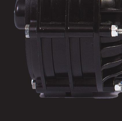
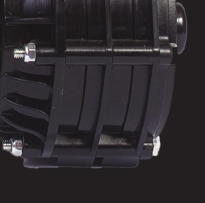
7 Figure 1: Tank inlet and outlet position Multiple cold water storage tanks MUST be linked in 28mm pipe work with the bottoms of the tanks at the same level. Figure 2: Linked cold water tanks Figure 3: ot water supply method 3. Anti-vibration couplers (oses) The anti-vibration (AV) couplers are designed to limit the transfer of pump vibration to the associated pipe work. All Salamander AV couplers are ¾ BSP x 22mm push fit with built-in isolating valves. Note: the RP50PT and RP50PS are supplied with 15mm couplers with isolating valves 2.3 ot water requirements The stored hot water temperature must not exceed 60º (see page 17, Stored hot water temperature). The hot water supply to the pump must be via a Salamander approved method: The best hot connection from the cylinder is either A 3 4 NO STOP ESSEX FLANGE. See Figure 3 or Alternatively a Salamander S flange or other approved top entry flanges. See page 15/16. Never fit to top entry flange if the pump is fitted above the cylinder. Isolating valve shown in ON position on the inlets and outlets. Figure 4: Isolating valves 35 Do not bend hoses more than 35 Isolating valve shown in OFF position A Salamander S flange or one of the 22mm approved top entry flanges listed on page OR ALTERNATIVELY MAX 60 22mm No Stop Essex flange with 76mm dip pipe and birds beak cut end to limit air being drawn into the pump Indirect coil Pump inlet Outlets Pump inlet Pump at the base of cylinder Do not twist or kink the hose Figure 5: ouplers Ideally the AV couplers should be straight, 4
8 but they must NOT be twisted or bent more than 35º (this invalidates the warranty). See Figure 5 above. Each single pump is supplied with two couplers; one angled and one straight. The angled coupler should be attached to the pump inlet (on the side) and the straight coupler should be attached to the pump outlet (on the top). Each twin pump is supplied with four couplers; two angled and two straight. For all pumps, the inlets are on the side of the pump and the outlets are on the top of the pump. The AV couplers MUST only be tightened to finger tight plus one quarter turn. Mechanical tools must NOT be used to tighten coupler nuts as this may cause damage which will invalidate your warranty. 4 General plumbing The installation must comply with the relevant requirements or local by-laws. The pump MUST be mounted upright (shaft horizontal, not screwed down). Jointing compounds, Boss White, hemp or steel wool MUST NOT be used. Solder fluxes must not come into contact with the pump or AV couplers. The maximum static head should be 10m (equivalent to 100kPa/1.0 bar pressure) with the exception of the RP50TU where the maximum static head should be 5m (equivalent to 50kPa/0.5bar pressure) Pre-installation The plumbing installation must comply with The Water Supply (Water Fittings) Regulations 1999 and BS EN 806-4:2010 buildings regulations. 5 Electrical requirements The pump must be connected to the electrical supply using the mains cable with the attached plug. This plug must be connected to an accessible socket that has been installed in compliance with BS 7671 (I.E.T. Wiring Regulations). The plug must be accessible at all times. The pump must not be installed in a bathroom unless it is installed in an enclosed space accessible only with the use of a tool. If the supply cord is damaged, it must be replaced by the manufacturer, its service agent or similarly qualified person in order Pump RP55PS, RP80PS and RP120PS RP50PT RP75PT and RP100PT RP55SU, RP80SU, RP120SU and RP50TU RP75TU and RP100TU Fuse 3 amp 3 amp 5 amp 3 amp 5 amp We recommend that the pump is run for at least 5 minutes every 4 weeks in order to exercise all working parts. 5
9 Typical installations Right positive head pumps The selection of the Right positive head pump for a system will be determined by the resistance of, quantity of and pressure required by, the outlets. Figure 8: Whole house system Either side of these pumps can be used for hot or cold water. In these systems: Toilets MUST be fitted with an equilibrium ball valve. Figure 6: Right pump fitted in loft above cylinder outlet Usable capacity minimum 50 gallons per bathroom old water storage old water storage Inlet Outlet Air vents, both hot and cold Positive head 600mm or less possible negative head Min 600mm Vent and other services Inlet Outlet Vent and other services MAX 60 Inlet Inlet Outlet Outlet Fit an equilibrium ball valve MAX 60 No Stop Essex Flange MUST be used with an anti-gravity loop at least 200mm in depth The hot connection must be via an approved side or top entry flange (see page 16) Washing machine In positive head systems, allow for increased resistance of long pipe runs with multiple bends. The natural flow from the outlets MUST be at least 2 litres/min mixed on hot and cold. Usable capacity minimum 50 gallons per bathroom old water storage Positive head 600mm or less possible negative head The hot connection must be via an approved side or top entry flange (see page 16) Vent and other services MAX 60 Inlet Outlet Outlet Inlet 6
10 ! Pre-installation Right Universal Pumps - system operation and L.E.D. indication Right Universal pumps are designed to protect customers by responding to unexpected and unforeseen conditions. Right Universal pumps will only be switched OFF if the unexpected or unforeseen conditions are serious. Right Universal pumps capable of: Supply water temperature sensing Dry run protection Sensing chronic aeration or water starvation L.E.D indication of unforeseen system malfunction. System malfunction is indicated by three L.E.D s located on the top of the pump junction box. see Figure 9. NON RETURN VALVES MUST NOT be fitted in the discharge pipework between the pump outlets and the system outlets unless specified by Salamander Pumps. Figure 9: L.E.D. indicator IMPORTANT NOTE The OT and OLD pump ends are identified by RED (hot) and BLUE (cold) tie unting Protection Only after two hours of persistent ON OFF ON OFF hunting due to a dripping (tap or shower) outlet. Dry Run Production Only occurs in instances of chronic aeration or water starvation after two ON OFF ON OFF operation and 60 second recovery period. (Not available on RP50TU) Excessive Temperature Due to the hot water temperature exceeding acceptable limits. The pump will automatically reset to operate when the water temperature resets to normal Salamander R 7
11 Right universal pumps A right universal twin pump to a bathroom in a loft-conversion. Figure 10: Negative head The hot connection must be via an approved side or top entry flange (see page 16) Negative head old water storage Vent and other services MAX 60 Outlet Outlet Fit an equilibrium ball valve Right pumps (positive head) Right universal twin pumps to a whole house system. In these systems TOILETS must be fitted with equilibrium ball valve(s). Inlet Negative head systems Negative head systems exist where no natural flow of water goes to the outlet because either the outlet or the pipework to the outlet are above the height of the base of the cold water cistern. Most instances of negative head systems occur in loft conversions or where the cold water cistern sits on the joists in the loft. If the distance between the bottom of the cold water cistern and the highest point of the system after the pump is 2 feet (610mm) or less, it is also possible that a universal pump will be required. Salamander s universal range of pumps activates the pump automatically even where no natural flow exists. Negative head is also needed for electric showers, dishwashers, washing machines or where pumped hot water meets mains cold. Figure 11: Positive head Usable capacity minimum 50 gallons per bathroom old water storage Positive head 600mm or less possible negative head Vent and other services MAX 60 Inlet Inlet Outlet Outlet Fit an equilibrium ball valve The hot connection must be via an approved side or top entry flange (see page 16) Washing machine 8
12 Typical installations Right Universal Pumps Right universal pumps to shower columns or steam shower cabinets These systems will be Negative ead where the pipework runs above the tank. Figure 12: Right universal pump to a shower column Usable capacity minimum 50 gallons per bathroom old water storage Single-ended Right Universal pump The following systems are best accommodated by using a single-ended Right Universal pump which is complete with a pressure vessel and electronic system protection. Right universal pump to boost tank fed supplies to instantaneous electric showers and water heaters. Figure 13: Instantaneous electric showers and 600mm or less possible negative head Inlet Outlet Outlet Air vents, both hot and cold 600mm or less possible negative head Usable capacity minimum 50 gallons per bathroom Vent and other services MAX 60 No Stop Essex Flange MUST be used with an anti-gravity loop at least 250mm in depth Right pump universal to a shower cabinet. Shower columns and steam shower cabinets in larger whole house systems or systems with multiple bathrooms will be best served by two single-ended Right Universal pumps. water heaters Tank fed, pressurised cylinder or combination boiler system with singleended Right Universal pump to boost the hot supply water pressure and cold water mains supplies cold to shower, bath, basin and toilet. 9
13 Figure 14: Pressurised cylinder or ombination boiler system Usable capacity minimum 50 gallons per bathroom old water storage 600mm or less possible negative head ombi boiler Double acting non-return valves must be fitted to cold inlets of any shower valve or mixer tap Fit an equilibrium ball valve Incoming cold water mains Tank fed (hot) with cold water mains systems MUST use Right Universal pumps Never use a single-ended Right Universal pump after the shower valve or before an open outlet. Figure 15: Tank fed (hot) with mains cold old water storage Usable capacity minimum 50 gallons per bathroom MAX 60 Double action non return valves Incoming cold water mains 10
14 !! ommissioning Before you finish Flush inlet pipework and carefully fill pump with water by discharging water from the outlet flexible coupler into a container. Fit pump inlet filters. It is RITIAL to discharge water through the pump into a container using natural flow before connecting the pump to outlet pipework in order to ensure the air has been discharged from inlet pipework and pump chambers. This will not happen if the outlet pipework is connected to the pump. The best method is:- Figure 19 DO NOT RUN PUMP DRY to do so will cause irreparable damage to your pump and will invalidate your warranty. Open shower mixer valve/system outlets to maximum hot and cold to check the natural flow (unpumped) flow of at least 1 litre per minute positive head systems. Open hot water outlets fully for 5 to 6 seconds and then turn outlets off. Then open cold water outlets fully for 5 to 6 seconds and turn outlets off. If flow is poor and inconsistent repeat above steps until flow is steady. Repeat 2-3 times. The hot connection must be via an approved side or top entry flange MAX 60 onnect discharge pipework. heck that all the pump isolating valves are open. Fill system. heck for leaks. 11
15 elpful old water supplies and storage Recovery of cold storage The typical recovery rate of a 1 2 inch high pressure part II BS1212 ball valve is: 100 kpa (15PSI/1.0 bar) 0.97 galls/min kpa (30PSI/2.0 bar) 1.34 galls/min kpa (40PSI/2.7 bar) 1.58 galls/min kpa (60PSI/4.0 bar) 1.94 galls/min 8.82 Aeration of pump and cylinder from a cold water storage tank This occurs when the incoming cold mains ball valve is positioned above the cold feeds to the cylinder and to the pump aerated water is drawn into the pump as illustrated. Figure 20: Aeration Vortex Outlets to pump The bottom of the cold tank MUST be checked and cleaned of debris Reposition cold mains ball valve here hronic aeration of the pump occurs when this problem is combined with inadequate storage capacity and/or when the volume of water drawn by the pump and other services exceeds the refill rate and creates a vortex which draws air and possibly debris into the guidelines pump. Pre-installation old storage usable capacity The usable capacity of cold storage is easily calculated as the capacity of water in the cold tank above the cold feeds to the cylinder, the pump and other outlets see formula. Formula for calculation on rectangular tank: Depth (15 ) x width (23 ) x length (36 ) = 12,420 cu inches Volume cu inches (12,420) x = litres Volume litres (203.56) x 0.22 = gallons. Formula for calculation on circular tank: Depth (15 ) x radius (17 ) x radius (17 ) x (Pi) = 13,621 cu inches Volume cu inches (13,621) x = 223 litres Volume litres (223) x 0.22 = 49 gallons. Figure 21 Width Usable capacity Length Depth of water Outlets The bottom of the cold tank MUST be checked and cleaned of debris 12
16 Pre-plumbed direct or indirect combination units These are purpose-made units typically for use in multiple flat developments, usually in towns and cities where it is advantageous and desirable to provide the occupants with completely independent hot and cold water services. In these systems the ideal pump is an RP50/75 TU. For alternative types of combination units see Elson, Figure 23 and Fortic (type), see Figure 24. Figure 22: Pre-plumbed direct or indirect combination units Elson (type) tanks In these systems it is important to ensure the hot and cold water storage capacity is adequate for the type of pump to be used. The refill ball valve on the small cold tank which refills the hot tank is correctly set to prevent aeration of the hot supply water to the pump. Figure 23: Elson (type) tanks Refill ball valves old mains ball valve Lid old tank ot tank old water storage Immersion heaters Immersion heater and an indirect connection to a boiler MAX 60 Fortic (type) tanks and pre-assembled units Typically used in very small flats and houses. Not usually with sufficient water capacity of cold water for pumped systems. Figure 24: Fortic (type) tanks and pre-assembled units Small cold water storage tank ot outlet 13

17 elpful guidelines Pre-installation Water starvation protection, pipework arrangements and stored hot water Please be advised due to lack of cold water storage with Elson and Fortic (type) tanks, our pumps may not be suitable. It is advisable to contact our Technical Support team before installing the pump on , otherwise it may affect your warranty. Water starvation protection In systems where it is absolutely not possible to increase the usable cold water storage capacity to meet the increased demand of a pumped system; a water starvation protection unit (WSP) may be considered. The WSP is a Salamander level switch which must be positioned 102mm higher than the highest outlet from the cold water storage tank. When the water level drops too far the WSP will switch off the pump until the cold water storage level is recovered. Figure 25: Water starvation protection unit (WSP) 102mm Outlets Water starvation protection unit (WSP) Shower head size vs bar pressure The size of a shower head dictates the bar pressure of the pump required to deliver the expected performance of the shower. Shower head diameter Up to 5cm 5-10cm cm More than 12.5cm Bar pressure 1.5 bar (150 kpa) 2.0 bar (200 kpa) 2.5 bar (250 kpa) 3.0 bar (300 kpa) Anti-gravity loops An anti-gravity loop (AGL) must always be fitted to systems where the pump is positioned above the hot outlet from the cylinder. The AGL which limits aeration of the hot supply to the pump is formed by bending the pipework downwards for 250mm, as it exits the Essex Flange, before rising again to the pump. See Figure 26 overleaf. 14
18 Figure 26: Anti-gravity loop (AGL) Figure 28: orizontal cylinders old water storage 600mm or less possible negative head Inlet Outlet Outlet Air vents, both hot and cold Non-return valve hot outlet only except ESP pumps Usable capacity minimum 50 galls per bathroom MAX 60 Use any of the approved top entry flanges Vent and other services MAX 60 No Stop Essex Flange MUST be used with an anti-gravity loop at least 250mm in depth ombi boilers and water heaters As these appliances are invariably supplied directly from the cold mains they are not normally suitable for booster pumps. The exceptions are featured in Figure 14 on page 10. Figure 27: ombi boilers WRONG ombi boiler Approved flanges (cylinders) The 22mm No Stop Essex and the other approved top entry flanges with extension pipes into the cylinder represent the best known means of ensuring minimal aeration of the hot supply water to the pump. The No Stop Essex flange is in all circumstances the best option. S flange omplete with compression pump and open vent connections. Also supplied with an adaptor to connect to 1 male and female top entry cylinders. Figure 29: S flange To vent S flange Incoming water main OT WATER YLINDER To pump orizontal cylinders As horizontal (torpedo) cylinders are problematic for boosted systems consult PumpWise for guidance and correct use of an approved top entry flange. 15 York flange These may be used in systems where the hot water requirement is less than 20 Litres per minute.
19 Warix flange A The Vent connection MUST be from side in Warix Flange. B The supply connection to the pump MUST BE FROM TE TOP of the Warix Flange via a 22mm compression elbow and thereby avoid inverted loops. In systems where there are one bathroom and an en-suite shower. Or two or more bathrooms the cold feed to the cylinder MUST be in 28mm pipework. Figure 30: Approved flanges Figure 31: Inverted loops WRONG Inverted loop Unpumped outlets A Never less than 1.2m for any top entry flange MAX 60 B Usable capacity minimum 50 gallons per bathroom Warix flange Inverted loops An inverted loop in the supply pipe-work to the pump, particularly on the hot side as illustrated; is likely to: interfere with the initiation and smooth operation of the pump. restrict the supply water to the pump and risk internal mechanical damage. Primatic cylinders and Andrews type water heaters are not suitable for pumped systems. Water hammer protection Water hammer most commonly occurs in systems where there are long pipe runs supplying solenoid activated appliances e.g. washing machines or outlets with quick acting/turn taps/ valve(s). The harmful effect of water hammer shock waves can be cushioned by fitting a pressure vessel unit, into the supply pipework as close as possible to the outlet from which the shock waves are originating. Figure 32: Water hammer protection Washing machine Pressure vessel 16
20 Pump hunting protection In negative head systems all the discharge pipework after the pump is pressurised. In such systems there exists the possibility the pump will hunt ON-OFF-ON etc at intervals. This will happen: if all outlets are not fully closed if there is a leak at a connection if boosted toilets are not fitted with equilibrium ball valves or as residual hot water contracts in long pipe runs. The irritating effects of hunting are cushioned by the pressure vessel which is an inbuilt feature of Right Universal pumps. Stored hot water volume In calculating the volume of the stored hot water requirement it is important to consider: number of bathrooms, with particular attention to the size of the bath number of persons in household time spent in shower e.g. 10mins in a 5 gall/minute shower will use up 50 galls/227 Litres of the cold water storage capacity approx 60% of which (30 gallons/136 Litres) will be hot water from the cylinder. hot water system it is recommended that the stored water temperature is controlled independently from that on the primary circuit. Extract from BS6700:1997 Under normal conditions the temperature of stored hot water should never exceed 65. A stored hot water temperature of 60 is considered sufficient to meet all normal requirements and will minimise scale deposits in hard water areas. Effective control of stored hot water is simply achieved by use of a cylinder thermostat and zone valve or direct acting thermostatic valve (e.g. tapstat). In systems where the stored hot water temperature is not controlled eg Aga solid fuel appliance or very crudely by the boiler thermostat, use a WS Blending valve controller. WS Blending valve controller The WS Blending valve controller is designed to protect booster pumps in Usable capacity minimum 50 galls per bathroom Vent and other services Not for RSP/RP or ESP an be off the vent if this distance is at least 1.5 metres Stored hot water temperature Extract from BS5546:1990 (urrent) The mean temperature of the stored water should not normally exceed 60 and in a combined central heating and domestic Surrey or No Stop Essex Flange MAX 60 WS Blending valve controller is factory set at 55 60º 17
21 Applications All Salamander pumps are designed to boost low pressure hot and cold supplies from tank-fed services. Voltage volts 50 z. Motor type apacitor start and run induction type motor with stainless steel shaft and in-built resetting thermal protection (complies with BS5000 part 11). Pump materials All moulded components are manufactured from Acetal opolymer. Maximum head RP 50 TU and RP 55 SU 5 metres All other pumps 10 metres Pumps fitted with RM3 maximum 3 metres static head. Pump noise With the technological advances achieved in Right pumps, Salamander has taken another step forward in the quest to supply all our customers with even quieter centrifugal pumps. Despite this no pump is completely silent. orrect installation will minimise vibration and transmission noise. Patents Our Right range of pumps is protected by following patent: ydraulic Pump - GB Mechanical seals Scale deposits in water supplies can cause the mechanical seal to stick if left for long periods without use. We recommend the pump be ran at least five minutes every four weeks to exercise all working parts. onnections 3 4 BSP male. Initiation Fully automatic, flow switch operated, requiring 1 litre in 30 sec per side or 2 litre in 30 sec mixed. Except Right Universal pumps when required to operate in negative head mode. Temperature Maximum fluid temperature 60º. Standards and approvals Splash proof rating IPX2. omplies with the requirements of current British and European safety standards for household and similar electrical appliances. omplies with European ommunity Directives (E). The company operate a policy of continuous development and reserves the right to change any of the specifications of its products without prior notice. All information data and illustrations given in this leaflet may be subject to variation. 18
22 Pump Model RP50PT RP75PT RP100PT RP50PS RP80PS RP120PS General Guarantee 2 Years Features Pump Type entrifugal Mechanical Seal Nitrile/arbon/eramic Inlet Isolator(s) Flexible oses Dry Run Protection Performance 16lpm 1.0 bar 1.2 bar 2.7 bar 1.0 bar 1.8 bar 3.0 bar 8lpm 1.2 bar 1.6 bar 2.9 bar 1.2 bar 2.1 bar 3.3 bar losed head 1.5 bar 2.0 bar 3.1 bar 1.5 bar 2.4 bar 3.6 bar Maximum Water Temperature 60 onnections Pump onnections 3/4 BSP Flexible hoses onnections (UK Model) onnections (ROI Model) 3/4 Female x 22mm push-fit x 280mm long, isolating valves on all hoses 3/4 Female x 21mm push-fit x 280mm long, isolating valves on all hoses Motor Type A. Induction Motor Duty Rating ontinuously Rated Elecrical Power supply 230 V urrent (full load) 1.30 amps 3.10 amps 4.40 amps 1.20 amps 1.70 amps 2.20 amps Power consumption 320 watts 740 watts 1050 watts 250 watts 400 watts 520 watts Fuse rating 3 amps 5 amps 3 amps Power cable (pre-wired) 1.5 metres 19
23 Pump Model RP50TU RP75TU RP100TU RP50SU RP80SU RP120SU General Guarantee 2 Years Features Pump Type entrifugal Mechanical Seal Nitrile/arbon/eramic Inlet Isolator(s) Flexible oses Dry Run Protection Performance 16lpm 1.0 bar 1.6 bar 2.5 bar 1.0 bar 1.9 bar 2.9 bar 8lpm 1.2 bar 1.9 bar 2.8 bar 1.3 bar 2.1 bar 3.2 bar losed head 1.5 bar 2.1 bar 3.0 bar 1.5 bar 2.3bar 3.4 bar Maximum Water Temperature 60 Pressure Vessel Air Pre- harge 8 psi 14 psi 20 psi 8 psi 14 psi 20 psi onnections Pump onnections 3/4 BSP Flexible hoses onnections (UK Model) 3/4 Female x 22mm push-fit x 280mm long, isolating valves on all hoses onnections (ROI Model) 3/4 Female x 21mm push-fit x 280mm long, isolating valves on all hoses Motor Type A. Induction Motor Duty Rating ontinuously Rated Elecrical Power supply 230 V urrent (full load) 1.30 amps 2.70 amps 4.50 amps 1.20 amps 1.70 amps 2.20 amps Power consumption 320 watts 640 watts 1050 watts 250 watts 400 watts 500 watts Fuse rating 3 amps 5 amps 3 amps Power cable (pre-wired) 1.5 metres 20
24 Fault Probable cause Recommended solution Pump will not start Electrical heck power supply heck fuse heck circuit breaker Pump will not start Right Universal pumps additional checks Inlet/outlet connections incorrect heck that connections are plumbed the correct way round and all valves are open Insufficient gravity flow heck that installation complies with Salamander instructions heck suitability of pump is installation in negative head (see page 9) heck inlet filters are not blocked heck flow rate min of 2l/min required on both hot and cold Float sticking in outlet Ensure no debris is in outlet area Flow switch malfunction ontact PumpWise on L.E.D. warning light lit L.E.D. 1 lit (pump hunting) See below conditions heck all outlets are fully closed and there are no leaks on outlet pipe work If fitted to toilets ensure ball valve in cistern is not passing water Ensure equilibrium ball valve fitted L.E.D. 2 lit (aeration starvation of water) L.E.D. 3 lit (temperature) heck cold water storage is correct for installation and pump is fitted to Salamander instructions Flange fitted heck pump filters are clear of debris Is effective temp control fitted (cylinder stat or WS/TMV valve)? 21
25 Fault Probable cause Recommended solution Reduced/ intermittent flow Pump starts with all outlets closed Incorrect or no anti-aeration flange Insufficient gravity flow heck that installation complies with Salamander instructions See above Blocked inlet filters Ensure that all filters and shower head are free from debris ouplers restricting flow Ensure that all AV couplers are straight and not bent or Air in system Run system on full hot with pump switched off (i.e. gravity only) for several minutes heck cold water storage is correct for installation and pump is fitted to Salamander instructions Ensure cold water refill rate is adequate for installation heck that vents are fitted as described in instructions Wrong size pump for system Ensure pump is sufficient to run the equipment ot temp set too high Reduce cylinder stat setting to 60º max or fit WS/TMV Leak in system Outlet open heck for leaks Pump is noisy Air in system See above Pump is leaking Pump vibrating on AV couplers causing vibration Pump exposed to mains water pressure Pump has suffered chemical damage Pump exposed to excessive temperature Pump appears to have leaked but not sure Ensure all outlets are fully closed or capped i.e. no dead legs in pipework Ensure rubber feet are fitted to pump Ensure that all AV couplers are straight and not bent or distorted heck that installation complies with Salamander instructions Ensure that the pump has not come into contact with chemical substance i.e. solder flux Is effective temp control fitted (cylinder stat or WS/TMV valve)? heck leak is not from fitting in pipework above pump 22

26 and warranty Monday to Thursday 8.30am to 5.30pm Friday 8.30am to 5.00pm. PumpWise is the cornerstone of Salamander s support service to customers and the means by which our customers are guaranteed: Selection of the right pump for the job With more than 30 pumps in our range, the PumpWise team can help you to choose the pump that s most suitable to your specific installation The avoidance of installation pitfalls Due to the technical nature of our products, it is essential that they are fitted according to our installation guidelines. The PumpWise team are available to talk through any installation questions and provide technical support and guidance. A third year s warranty FREE All of our right pumps come with a full two year warranty, but following installation of your new pump, if your installer calls our PumpWise team, registers your pump and runs through the system installation you may be eligible for a third years warranty free. Our PumpWise commitment Our PumpWise helpline is here to help you and we aim to provide a support service second to none. Installers and customers can be sure of a speedy response to requests for technical help, guidance and advice. Your warranty Salamander customers benefit from a full two year warranty on the Right pump range. This warranty will operate from the date of purchase and is subject to the installation guidelines being followed correctly (please refer to our Pre- hecklist, on page 2 and our ommissioning hecklist, on page 11). This warranty could be increased free of charge, if the installer contacts our Pumpwise team on at the time of initial installation, to register the pump and run through the installation with our Technical Team. Providing the pump has been installed according to our guidelines, you will receive a third year s warranty free of charge (UK only). Please complete and return the attached warranty card. Extended warranties In addition to the three year warranty available free of charge following the successful installation of your pump, there is an optional Extended Warranty Scheme (UK only). The Extended Warranty Scheme exists to protect customers from any unexpected or unforeseen pump breakdowns. Participation in the Extended Warranty Scheme is activated by completion of an Extended Warranty Application Form and the payment of a nominal fee. For further details please contact the PumpWise team: Telephone: Fax: tech@salamanderpumps.co.uk PLEASE NOTE: Incorrect installation may invalidate the pump warranty. 23
27 To the installer Please follow the guidelines for installation provided in this brochure and call the PumpWise helpline for installation advice. Once installation has been completed and the system has been tested to your satisfaction, please assist the customer in completing the prepaid Warranty ard. Terms, conditions and war ranty 1 The Scope of the Warranty SALAMANDER PUMPED SOWER SYSTEMS LTD ( the company ) Warrants subject to the terms and conditions below for the Warranty period(s) specified in paragraph 3 that the ompany shall: Repair or replace free of charge the product(s) specified on the Warranty card or any component part thereof (together referred to as the equipment ) which shall in the opinion of the ompany have proved defective by reason only of the ompany s materials or workmanship providing always that the ompany shall be under no obligation whatsoever under this Warranty to repair or replace equipment which have been misused, tampered with, modified/altered in any way without the consent in writing of the ompany or if any component or accessory shall have been replaced by a type not specified by the ompany or if the equipment is incorrectly installed or operated or used other than as described in the instruction manual or if any servicing or repair of the equipment shall have been carried out otherwise than by an authorised ompany dealer appointed by the ompany ( dealer ). The ompany s liability under this Warranty is limited to the said repairs or replacement and shall under no circumstances extend to any financial loss or damage including consequential losses alleged to have been suffered by the claimant. Subject as provided in this warranty and except where the equipment is sold to a person dealing as a consumer all warranties, conditions or other terms implied by law are excluded to the fullest extent permitted by law. Nothing in this warranty shall exclude liability for death or personal injury caused by the ompany s negligence 2 Terms and conditions This Warranty shall only be enforceable by you if the following terms and conditions have been complied with: a That the pump has been installed in accordance with the installation instructions, guidance and advice contained within the installation and warranty guide and/or provided by the Salamander help desk. b You are the original purchaser of the equipment from a dealer and not an assignee or subsequent purchaser of the equipment. c You must evidence the date of purchase by retaining the original invoice from the dealer. Without such evidence the ompany reserves the right to reject any such claims under the terms of this Warranty. d Within 15 days of delivery of the equipment to you the Warranty card is accurately completed and returned to the ompany. e Within 30 days of discovery of a defect giving rise to liability under paragraph 1 above you give notice thereof in writing to the ompany. f Provided the pump has not been altered, tampered with, modified or transformed in any way. 3 The Warranty periods The Warranty periods referred to in paragraph 1 above are as follows: a Products manufactured by the ompany 2 years from date of purchase provided the warranty card is completed and returned to the ompany within 15 days of purchase. b Products supplied by the company, but are not of the company s manufacture come with 30 day warranty from date of purchase. Anti-Vibration ouplers (hoses) come with 1 year from date of purchase. c The warranty period in respect of any product repaired or replaced under the warranty shall be part of the above period(s) which remain unexpired. d In the event of a claim for repairs or replacement being made under the terms of this Warranty, a visit from a Salamander service engineer may be necessary. Engineer visits are not covered under/ part of the warranty agreement. In circumstances where in the opinion of the ompany the defect has not been caused by the ompany s materials or workmanship, then the ompany reserves the right to charge the claimant at its current hourly rates and list prices in respect of any service engineer s time and replacement of any parts. Please speak to our Technical Support team for further details and confirmation of costs. e This Warranty is given in addition to and does not affect your statutory rights as a consumer. f This Warranty is valid and enforceable for equipment purchased and used exclusively within the UK and the Republic of Ireland only. g Where the ompany issues a replacement the equipment replaced shall be returned to the ompany forthwith and shall become the property of the ompany. 24
28 Notes 25
29 DDATTDTFDADDTADDTTFATTDADFDDATDDDFDD Freepost RLXE-JY-LJ Salamander Pumps Unit 2c olima Avenue Sunderland SR5 3XE
SHOWER PUMPS. Installation Manual. 1.5 bar and 2.0 bar
 SHOWER PUMPS 1.5 bar and 2.0 bar Twin and single ended pumps designed specifically for gravity feed or stored water systems where the hot water is fed from a hot water cylinder and the cold from a cold
Pump installation and warranty guide for the CT range of pumps
 X132219_SP_p3_lh_X132219_SP_p3_lh 31/03/2014 17:28 Page 1 Quality Technology Service Value Pump installation and warranty guide for the CT range of pumps CT FORCE CT Xtra 15 PT, 15 TU, 15 IPT, 15 ITU 20
Pump installation and warranty guide for the CT range of pumps
 Quality Technology Service Value Pump installation and warranty guide for the CT range of pumps CT FORCE, CT Xtra, and CT Bathroom ISSUE E JAN 2017 Models shown: CT FORCE 15PT CT 50 Xtra CT 60BU Bathroom
Turboboost SHOWER PUMPS. Installation Manual. 1.5 bar and 2.0 bar
 Turboboost SHOWER PUMPS 1.5 bar and 2.0 bar Twin and single ended pumps designed specifically for gravity feed or stored water systems where the hot water is fed from a hot water cylinder and the cold
Pump installation and warranty guide for the CT range of pumps
 Pump installation and warranty guide for the CT range of pumps CT FORCE, CT Xtra, and CT Bathroom Models shown: CT FORCE 15TU CT50 Xtra CT60B ISSUE G JUL 2018 Pump installation and warranty guide for the
Pump installation and warranty guide for all pumps
 Salamander Pumps Pump installation and warranty guide for all pumps making life easier for plumbers ISSUE 13 NOVEMBER 2010 Pump installation and warranty guide Important read this first! orrect installation
CT range. of shower, bathroom and whole house pumps
 CT range of shower, bathroom and whole house pumps 2 Salamander Pumps is one of the UK s leading manufacturers of shower and domestic water pumps. Innovation is used throughout the organisation to create
SMART SHOWERS ELITE SP P0985 READ ME THIS IS A HIGH PERFORMANCE HIGH SPECIFICATION PUMP AND HAS PRECISE INSTALLATION REQUIREMENTS
 ELITE SP P0985 80TX, & 150TX SUPERGEN TWIN SHOWER PUMP READ ME THIS IS A HIGH PERFORMANCE HIGH SPECIFICATION PUMP AND HAS PRECISE INSTALLATION REQUIREMENTS THIS DOCUMENT SHOULD BE PASSED TO THE HOUSEHOLDER
SHOWERBOOST BATHROOMBOOST HOUSEBOOST TECHNICAL WHY BUY A PUMP? Designed to boost the performance of a single outlet, ie a shower, tap or appliance.
 3 Many homes experience water pressure problems, from dribbling taps, slow filling toilet cisterns and less than satisfying shower experience, that s where our products can help... WHY BUY A PUMP? SHOWERBOOST
Boost your water pressure. Shower, bathroom and whole house pumps
 Boost your water pressure Shower, bathroom and whole house pumps Many homes experience water pressure problems, from dribbling taps, slow filling toilet cisterns and less than satisfying shower experiences,
PERFORMANCE SHOWER PRODUCTS
 INSTALLER PLEASE LEAVE INSTRUCTIONS WITH CUSTOMER PERFORMANCE SHOWER PRODUCTS INSTALLATION INSTRUCTIONS FOR REGENERATIVE MAINS SHOWER PUMP Model: PR35D Medium pressure twin PR50D Medium pressure twin PR50S
T550i power shower pump Installation and operating instructions
 power shower pump Installation and operating instructions Installers please note these instructions are to be left with the user 2180149H March 2008 CONTENTS Page Plumbing and electrical notes...1 Introduction...2
Bath Shower Mixer
 86004490 Bath Shower Mixer Installation and operating instructions The showerhead and hose supplied with this product are a safety critical part of your shower. Failure to use genuine Triton parts may
HEAVY DUTY BRASS SHOWER PUMPS
 HEAVY DUTY BRASS SHOWER PUMPS YOUR GUARANTEE IS AT RISK IF PUMP NOT INSTALLED CORRECTLY. SEE SECTION 2 IMPORTANT INSTRUCTIONS Performance Shower Products SERVICE HELPLINE TEL: 01883 730339 1. GENERAL Your
PLEASE LEAVE THIS MANUAL WITH THE OSO UNIT AFTER INSTALLATION INSTALLATION MANUAL
 PLEASE LEAVE THIS MANUAL WITH THE OSO UNIT AFTER INSTALLATION SOLARCYL IM/SC INSTALLATION MANUAL This manual gives detailed advice for installation and should be read carefully prior to fitting any unvented
WC2 & WC3 Installation & Maintenance Instructions
 WC2 & WC3 Installation & Maintenance Instructions Please leave this instruction booklet with the home owner as it contains important guarantee, maintenance and safety information WC3 shown WC2 WC3 IMPORTANT
SEALED THERMAL STORE
 ISSUE 3 0717 INSTALLATION AND USER GUIDE ENERGYMANAGER SEALED THERMAL STORE ADVANCE APPLIANCES LTD PLEASE RETAIN AND ENSURE SERVICE RECORDS ARE KEPT UP TO DATE. SCHEMATIC DIAGRAM OF ENERYMANAGER THERMAL
Dene Bath Shower Mixer
 Dene Bath Shower Mixer Installation and operating instructions The showerhead and hose supplied with this product are an integral part of the safety of your shower. Failure to use genuine Triton parts
Installation, Operation & Maintenance Instructions
 Installation, Operation & Maintenance Instructions Please leave this instruction booklet with the owner as it contains important guarantee, maintenance and safety information Read this manual carefully
Flo~mate Mains Boost Pump Installation & Maintenance Instructions
 ~ Flo~mate Mains Boost Pump Installation & Maintenance Instructions Please leave this instruction booklet with the owner as it contains important guarantee, maintenance and safety information FOR POSITIVE
Vented systems explained Performance without compromise Vented System (Gravity Fed) Positive Head Systems
 Positive Head Systems") Vented systems explained Vented System (Gravity Fed) Typically used in older properties, this indirect system uses the mains water supply to feed a cold water storage tank, usually located in the roof
Vented systems explained Vented System (Gravity Fed) Typically used in older properties, this indirect system uses the mains water supply to feed a cold water storage tank, usually located in the roof
Flomate Mains Boost Pump Installation & Maintenance Instructions
 Flomate Mains Boost Pump Installation & Maintenance Instructions Please leave this instruction booklet with the owner as it contains important guarantee, maintenance and safety information PATENT APPROVED
Installation, Operation & Maintenance Instructions
 Installation, Operation & Maintenance Instructions Please leave this instruction booklet with the owner as it contains important guarantee, maintenance and safety information Read this manual carefully
BOILING UNIT REDITAP. Installation and User Guide. IMPORTANT: This booklet should be left with the user after installation and demonstration
 in tap Boiling water to in tap sink Drain Valve (as high as possible) REDITAP CONNECTION SUMMARY Amp mains supply cold mains water into in tap optional filter cold water in hot water BOILING UNIT Installation
Aquamixa. Thermo. Thermostatic shower valve with manual bath fill
 Aquamixa Thermo Thermostatic shower valve with manual bath fill Aquamixa Thermo thermostatic shower valve with manual bath fill installation instuctions page 1 Shower systems Aquamixa Thermo (300.01) with
Installation, Operation & Maintenance Instructions
 Installation, Operation & Maintenance Instructions Please leave this instruction booklet with the owner as it contains important guarantee, maintenance and safety information Read this manual carefully
Installation Instructions For Showermate Eco Shower Booster Pumps S1.5 bar Twin, S2.0 bar Twin, S2.0 bar Single
 Installation Instructions For Showermate Eco Shower Booster Pumps S.5 bar Twin, S2.0 bar Twin, S2.0 bar Single INDEX...................... Page No Product Description................ Application.......................
CROMO manual mixer shower
 CROMO manual mixer shower CAUTION! THIS PRODUCT IS NOT THERMOSTATICALLY CONTROLLED Installation and operating instructions Installers please note these instructions are to be left with the user 2180810C
Manual and Thermostatic Power Shower Units
 520M/520TS Manual and Thermostatic Power Shower Units Installation instructions & User guide IMPORTANT: This booklet should be given to the customer after installation and demonstration. WARNING: Under
Sema thermostatic bar mixer Installation and operating instructions
 Sema thermostatic bar mixer Installation and operating instructions Installers please note these instructions are to be left with the user 2180579A September 2006 CONTENTS Page Introduction 1 Safety warnings
NENE. Installation and Operating Instructions. Thermostatic bar mixer shower PLEASE NOTE THESE INSTRUCTIONS ARE TO BE LEFT WITH THE USER
 NENE Thermostatic bar mixer shower Installation and Operating Instructions INSTALLERS PLEASE NOTE THESE INSTRUCTIONS ARE TO BE LEFT WITH THE USER 2180430B October 2005 CONTENTS Page Introduction 1 Safety
Installation, Operation & Maintenance Instructions
 Installation, Operation & Maintenance Instructions Please leave this instruction booklet with the owner as it contains important guarantee, maintenance and safety information Read this manual carefully
Cylinder Manual. Open Vented Cylinders Stainless Steel Water Heaters. Twin Coil TW180V TW210V TW250V TW300V Triple Coil TR250V TR300V
 Cylinder Manual Incorporating: User Instructions Installation Instructions Guarantee Registration Open Vented Cylinders Stainless Steel Water Heaters Products covered by this manual: Twin Coil TW180V TW10V
ADVANCE ECB ELECTRIC COMBINATION BOILER
 ISSUE ISSUE 45 0115 0317 INSTALLATION AND USER GUIDE ADVANCE ECB ELECTRIC COMBINATION BOILER ADVANCE APPLIANCES LTD HOUSEHOLDER - PLEASE RETAIN AND ENSURE SERVICE RECORDS ARE KEPT UP TO DATE 1 SCHEMATIC
Installation and User Guide Please leave this guide with the end user (for future reference)
") Contact and Commissioning Details Installer Contact Name and Address : Model N : Serial N : Date Installed : Installation and User Guide Please leave this guide with the end user (for future reference)
Contact and Commissioning Details Installer Contact Name and Address : Model N : Serial N : Date Installed : Installation and User Guide Please leave this guide with the end user (for future reference)
Oltis thermostatic bar mixer
 Oltis thermostatic bar mixer Installation and operating instructions Installers please note these instructions are to be left with the user 2180564E February 2009 CONTENTS Page Introduction... 1 Safety
PLEASE LEAVE THIS MANUAL WITH THE OSO UNIT AFTER INSTALLATION INSTALLATION MANUAL
 PLEASE LEAVE THIS MANUAL WITH THE OSO UNIT AFTER INSTALLATION 0 RD 0 RI 0000-06 IM/ IM/a INSTALLATION MANUAL This manual gives detailed advice for installation and should be read carefully prior to fitting
AIRE. Thermostatic bath shower mixer. Installation and Operating Instructions INSTALLERS PLEASE NOTE THESE INSTRUCTIONS ARE TO BE LEFT WITH THE USER
 AIRE Thermostatic bath shower mixer Installation and Operating Instructions INSTALLERS PLEASE NOTE THESE INSTRUCTIONS ARE TO BE LEFT WITH THE USER 2180427C October 2005 CONTENTS Page Introduction 1 Safety
Contents. Commissioning 6 Operation 6 Routine Preventative Maintenance 6 Fault Finding 7 Spares Parts 8 Technical Support 9
 Contents Product Description 2 Approvals 2 Warranty 2 Warnings 2 Technical Specification 3 Installation 4 Location 4 Plumbing Connection 4 Electrical connection 5 Commissioning 6 Operation 6 Routine Preventative
AQ150:Midas 10/9/15 14:50 Page 1 AQ150. Thermostatic bar mixer valve with adjustable head. Installation guide
 AQ150:Midas 10/9/15 14:50 Page 1 AQ150 Thermostatic bar mixer valve with adjustable head Installation guide AQ150:Midas 10/9/15 14:50 Page 2 Important information Introduction The product is an exposed
Please tape down. NewTeam Ltd. Customer Service Dept. Brunel Road Earlstrees Industrial Estate Corby Northants NN17 4JW
 3rd Fold 1st Fold NewTeam Ltd. Customer Service Dept. Brunel Road Earlstrees Industrial Estate Corby Northants NN17 4JW 2nd Fold Please tape down Please tape down Affix Stamp Installation Instructions
Thermostatic bar mixer valve with adjustable head Installation guide
 Bar valve Thermostatic bar mixer valve with adjustable head Installation guide Index Introduction p.3 - Safety information p.3 - Product specification p.3 Connection to supplies p.3 - Flushing p.4 - Filters
POWER SHOWERS Models 4500M 5002M 4500T 5002T
 II POWER SHOWERS Models 4500M 5002M 4500T 5002T Performance Shower Products CUSTOMER SERVICE HELPLINE: 01883 730339 CONTENTS PLEASE READ THESE INSTRUCTIONS CAREFULLY: This booklet covers all models in
Bar valve with fixed and adjustable shower heads. Installation guide. Midas Plus installation instructions Page 1
 Midas Plus Bar valve with fixed and adjustable shower heads Installation guide Midas Plus installation instructions Page 1 Midas Plus Midas Plus installation instructions Page 2 Components Literature not
TYNE. Installation and Operating Instructions. Thermostatic bar mixer shower. Installers please note these instructions are to be left with the user
 TYNE Thermostatic bar mixer shower Installation and Operating Instructions Installers please note these instructions are to be left with the user 2180431E - February 2013 CONTENTS Page Introduction...
Quartz. Digital. Bath with bath waste filler. Quartz Digital Bath with bath waste filler installation instuctions page 1
 Quartz Digital Bath with bath waste filler The Waste Electrical and Electronic Equipment (Producer Responsibility) Regulation 2004 This product is outside the scope of the European Waste Electrical and
Installation, Operation & Maintenance Instructions
 Installation, Operation & Maintenance Instructions Please leave this instruction booklet with the owner as it contains important guarantee, maintenance and safety information Read this manual carefully
Mira Atom ERD Thermostatic Bar Valve
 Mira Atom ERD Thermostatic Bar Valve These instructions must be left with the user Installation and User Guide 1 1340912-W2-A 1340912-W2-A 2 Introduction Thank you for purchasing a quality Mira product.
Mira Vision Wireless Controller
 Mira Vision Wireless Controller These instructions must be left with the user User Guide 1 128684-A2-A CONTENTS Introduction...3 Safety Information...3 Control Layout...4 Display Symbols...5 Using the
Please tape down. NewTeam Ltd. Customer Service Dept. Brunel Road Earlstrees Industrial Estate Corby Northants NN17 4JW
 3rd Fold 1st Fold NewTeam Ltd. Customer Service Dept. Brunel Road Earlstrees Industrial Estate Corby Northants NN17 4JW 2nd Fold Please tape down Please tape down Affix Stamp Installation Instructions
Installation, Operation & Maintenance Instructions
 Installation, Operation & Maintenance Instructions Please leave this instruction booklet with the home owner as it contains important guarantee, maintenance and safety information Read this manual carefully
INSTALLATION MANUAL. Ecoline Geo RI HP PLEASE LEAVE THIS MANUAL WITH THE OSO UNIT AFTER INSTALLATION
 PLEASE LEAVE THIS MANUAL WITH THE OSO UNIT AFTER INSTALLATION 142039-02 GEO 9-2015 Ecoline Geo RI HP INSTALLATION MANUAL The Ecoline GEO is an indirect unvented cylinder designed and approved for use with
ENERSTORE. Vented Hot Water Storage System INSTRUCTIONS PLEASE LEAVE WITH HOUSEHOLDER
 ENERSTORE Vented Hot Water Storage System INSTRUCTIONS PLEASE LEAVE WITH HOUSEHOLDER Newark Copper Cylinder Co Ltd Brunel Drive Newark Notts. NG24 2EG Tel: 01636 678437 Fax: 01636 678964 Internet: www.newarkcoppercylinder.co.uk
INSTALLATION MANUAL. Ecoline Geo RI HP PLEASE LEAVE THIS MANUAL WITH THE OSO UNIT AFTER INSTALLATION
 PLEASE LEAVE THIS MANUAL WITH THE OSO UNIT AFTER INSTALLATION Ecoline Geo RI HP INSTALLATION MANUAL The Ecoline GEO is an indirect unvented cylinder designed and approved for use with a heat pump. The
Installation Instructions Flute Tap Range
 Installation Instructions Flute Tap Range Models covered: FLT BAS C, FLT 1HBF C, FLT 2HBSM C, FLT TBAS C Please keep this booklet for future reference. Installer, when you have read these instructions
ADVANCE ELECTRIC THERMAL STORE
 ISSUE 13 1118 INSTALLATION AND USER GUIDE ADVANCE ELECTRIC THERMAL STORE ADVANCE APPLIANCES LTD HOUSEHOLDER PLEASE RETAIN AND ENSURE SERVICE RECORDS ARE KEPT UP TO DATE. 2 INTRODUCTION Advance thermal
Installation, Operation & Maintenance Instructions
 Installation, Operation & Maintenance Instructions Please leave this instruction booklet with the home owner as it contains important guarantee, maintenance and safety information Read this manual carefully
CROWN WATER HEATERS CPU10 - CPU15 CPOS10 - CPOS15
 CROWN WATER HEATERS CPU10 - CPU15 CPOS10 - CPOS15 COMPACT PLUS 10 and 15 Litre Unvented Under and Over Sink Water Heater INSTALLATION AND USER GUIDE 1 DIMENSIONS 10L - 250mm 15L - 310mm 100mm 80mm 410mm
Thermostatic bar mixer shower. Installation and Operating Instructions. Installers please note these instructions are to be left with the user
 Nene Thermostatic bar mixer shower Installation and Operating Instructions Installers please note these instructions are to be left with the user 2180430B October 2005 CONTENTS Page Introduction 1 Safety
Dove Eco thermostatic bar mixer shower
 Dove Eco thermostatic bar mixer shower Eco Statement This product has been fitted with a flow regulator to deliver a maximum flow rate of 6 litres per minute. Installation and operating instructions Installers
Installation and Servicing Instructions
 Installation and Servicing Instructions Zenex GasSaver GS-1 Passive Flue Gas Heat Recovery Device (PFGHRD) Recognised by the Government s Standard Assessment Procedure (SAP) IMPORTANT: Read these instructions
Thames thermostatic bar mixer with diverter Installation and operating instructions
 Thames thermostatic bar mixer with diverter Installation and operating instructions Installers please note these instructions are to be left with the user 2180452D July 2007 CONTENTS Page Introduction
Installation, Operation & Maintenance Instructions
 Installation, Operation & Maintenance Instructions Please leave this instruction booklet with the home owner as it contains important guarantee, maintenance and safety information Read this manual carefully
Total Hot Water Solutions
 H ot Wa te r Syste m s Copper Hot Water Products Total Hot Water Solutions www.copperform.co.uk selection guide Copperform Ltd is part of the Kingspan Hot Water Systems Group of companies, and manufactures
MANUAL MIXER SHOWER. Installation and operating instructions. Installers please note these instructions are to be left with the user CAUTION!
 MANUAL MIXER SHOWER CAUTION! THIS PRODUCT IS NOT THERMOSTATICALLY CONTROLLED Installation and operating instructions Installers please note these instructions are to be left with the user 2180586B July
Installation, Operation & Maintenance Instructions
 Installation, Operation & Maintenance Instructions Please leave this instruction booklet with the home owner as it contains important guarantee, maintenance and safety information Read this manual carefully
Mimosa dual control mixer shower Installation and operating instructions
 Mimosa dual control mixer shower Installation and operating instructions Installers please note these instructions are to be left with the user 2180443A September 2006 CONTENTS Page Introduction 1 Safety
Installation Instructions For Monsoon Universal Twin Pump
 Installation Instructions For Monsoon Universal Twin Pump Medium Pressure N1.5 bar High Pressure N2.5 bar High Pressure N3.5 bar High Pressure N4.1 bar INDEX........................Page No Product Description....................1
Installation Instructions and User Guide Thermostatic Recessed Dual Control Shower Valve
 Installation Instructions and User Guide Thermostatic Recessed Dual Control Shower Valve Models covered: SHP01. Please keep this booklet for future reference. Installer, when you have read these instructions
Pear Kitchen Sink Tap
 Pear Kitchen Sink Tap Installation Instructions & User Guide Please keep these instructions for future reference and request of replacement parts Contents Thank you for choosing Bristan, the UK s leading
MIDAS. Installation instructions 110/220
 MIDAS Installation instructions 110/220 INDEX INTRODUCTION Page 3 Safety information Page 3 Product specification Page 3 Important information CONNECTION TO SUPPLIES Page 4 Flushing Page 4 Filters Page
Thermostatic Shower Tower Installation and Operating Instructions
 Thermostatic Shower Tower Installation and Operating Instructions INSTALLERS PLEASE NOTE THESE INSTRUCTIONS ARE TO BE LEFT WITH THE USER 2180396D November 2005 CONTENTS Page Introduction 1 Safety warnings
Installation Instructions For Monsoon Universal Twin Pump
 Installation Instructions For Monsoon Universal Twin Pump Medium Pressure U1.5 bar Medium Pressure U2.0 bar INDEX................. Page No Product Description................... 1 Application..........................
TYNE. Installation and Operating Instructions. Thermostatic bath shower mixer. Installers please note these instructions are to be left with the user
 TYNE Thermostatic bath shower mixer Installation and Operating Instructions Installers please note these instructions are to be left with the user 2180426F - February 2013 CONTENTS Page Introduction...
INSTANTANEOUS ELECTRIC SHOWER
 GUARANTEE / SERVICE POLICY INSTANTANEOUS ELECTRIC SHOWER GUARANTEE Designa guarantee this DS3000 product for a period of two years, from date of purchase, against mechanical and electrical defects arising
Rise. Digital. Bath with overflow filler. Rise Digital Bath installation instuctions page 1
 Rise Digital Bath with overflow filler The Waste Electrical and Electronic Equipment (Producer Responsibility) Regulation 2004 This product is outside the scope of the European Waste Electrical and Electronic
ZIP Varipoint III. Installation, Maintenance and User Instructions. Models VP303, VP503 VP803, VP953 direct unvented water heaters. Issued August 2008
 Varipoint cover qxd:varipoint cover qxd 22/8/08 11:14 Page 1 Installation, Maintenance and User Instructions ZIP Varipoint III Models VP303, VP503 VP803, VP953 direct unvented water heaters Issued August
These instructions are to be left with the user
 ECO ADJUSTABLE HANDSET 1668.001 & 1668.002 Accessory Pack Installation & User Guide These instructions are to be left with the user 1 Introduction The Mira Eco adjustable shower handset has three different
MERSEY sequential exposed thermostatic mixer shower
 MERSEY sequential exposed thermostatic mixer shower Installation and operating instructions Installers please note these instructions are to be left with the user 2180773B - June 2013 CONTENTS Page MAIN
CENTRA-COIL QUALITY HOT WATER SERVICE
 CENTRA-COIL QUALITY HOT WATER SERVICE INSTALLATION AND OWNERS MANUAL WARNING This water heater should be installed in accordance with the requirements of AS 3500.4. The owner should also be aware of any
Thermostatic exposed shower valve and bath/shower mixer systems Installation guide
 Midas Thermostatic exposed shower valve and bath/shower mixer systems Installation guide 2 Index Introduction p.4 - Safety information p.4 - Product specification p.4 Connection to supplies p.4 - Flushing
Instantaneous Electric Over-Sink Hand Wash Installation and User Instructions
 3 Flow Instantaneous Electric Over-Sink Hand Wash Installation and User Instructions IMPORTANT This Step-by-Step guide should be given to the customer after installation and demonstration. CONTENTS 1.
Installation, Operation & Maintenance Instructions
 Installation, Operation & Maintenance Instructions Please leave this instruction booklet with the home owner as it contains important guarantee, maintenance and safety information Read this manual carefully
Eden Bath Shower Mixer
 Eden Bath Shower Mixer 86005120 Installation and operating instructions The showerhead and hose supplied with this product are a safety critical part of your shower. Failure to use genuine Triton parts
Delphi dual control thermostatic mixer shower Installation and operating instructions
 Delphi dual control thermostatic mixer shower Installation and operating instructions Installers please note these instructions are to be left with the user 2180607B January 2009 Contents Page Introduction...1
Parenzo Range. Basin Mixer, Bath Filler & Bath Shower Mixer. Assembly instructions
 Parenzo Range Basin Mixer, Bath Filler & Bath Shower Mixer Assembly instructions We have designed these products with your enjoyment in mind. To ensure that they work to their full potential, they need
Artisan Thermostatic Bath Filler
 Artisan Thermostatic Bath Filler Installation Instructions & User Guide Please keep these instructions for future reference and request of replacement parts General Information Thank you for choosing Bristan,
Furrows Business Park, Haybridge Road Wellington, Telford, Shropshire TF1 2FE
 WATERHEATER MANUFACTURERS ASSOCIATION Tel 01952 257963 Fax 01952 253452 Furrows Business Park, Haybridge Road Wellington, Telford, Shropshire TF1 2FE www.telford-group.com STAINLESS PRODUCTS Tornado &
Greenleaf 600 Macerator Toilet Waste Pump
 Greenleaf 600 Macerator Toilet Waste Pump Website: Contact: www. greenleaftrade.co.nz Introduction The Greenleaf 600 toilet macerator waste pump is suitable for use in domestic waste / sewerage installations.
Pressure Boosting Solutions
 GRUNDFOS Water Pressure Boosting Pressure Boosting Solutions 1 GRUNDFOS Water Pressure Boosting WHAT CAN CAUSE LOW WATER PRESSURE? Poor mains pressure Generally due to water companies reducing the supply
Nema manual bar mixer shower Installation and operating instructions
 Nema manual bar mixer shower Installation and operating instructions Installers please note these instructions are to be left with the user 2180534B July 2008 Contents Page Main components... 1 Introduction...
THERMOSTATIC SHOWER VALVE
 V8/3 THERMOSTATIC SHOWER VALVE PRODUCT MANUAL INSTALLER Please leave manual with user for future reference to unit operation and maintenance. 1 INTRODUCTION Meynell mixing valves are manufactured within
Installation, Operation & Maintenance Instructions
 Installation, Operation & Maintenance Instructions Please leave this instruction booklet with the home owner as it contains important guarantee, maintenance and safety information Read this manual carefully
Installation, Operation & Maintenance Instructions
 Installation, Operation & Maintenance Instructions Please leave this instruction booklet with the home owner as it contains important guarantee, maintenance and safety information Read this manual carefully
Zip Hydroboil. Installation and Operating Instructions. Filtered instant boiling water
 Installation and Operating Instructions Zip Hydroboil Filtered instant boiling water 01552 Zip Hydroboil 1.5 Litre White 01551 Zip Hydroboil 1.5 Litre Stainless Steel 03552 Zip Hydroboil 3 Litre White
MATINO thermostatic bar mixer shower Installation and operating instructions
 MATINO thermostatic bar mixer shower Installation and operating instructions Installers please note these instructions are to be left with the user 2180755A March 2009 Contents Page Main components...
Installation Instructions and User Guide Thermostatic Recessed Dual Control Shower Valve with Integral Diverter
 Installation Instructions and User Guide Thermostatic Recessed Dual Control Shower Valve with Integral Diverter Models covered: N2 SHCDIV C, N2 SHCDIV G, AR3 SHCDIV C, PM2 SHCDIV C, RS SHCDIV C, DSC SHCDIV
Vote for your Installer of the year at HEATSLAVE
 Vote for your Installer of the year at www.worcester-bosch.co.uk HEATSLAVE 12/14, 15/19, 20/25, 26/32 FLOOR-STANDING OIL-FIRED COMBINATION BOILERS FOR CENTRAL HEATING AND MAINS-FED DOMESTIC HOT WATER USER
MEGAFLO HE Iss 1
 MEGAFLO HE 1 36 00 5843 Iss 1 Contents Contents SECTION PAGE 1 INTRODUCTION... 3 2 GENERAL REQUIREMENTS... 4 3 INSTALLATION - GENERAL... 5 4 INSTALLATION - DIRECT UNITS... 8 5 INSTALLATION - INDIRECT UNITS...
OWNER S GUIDE SEQUENTIAL THERMOSTATIC SHOWER VALVE. 150mm Inlet Pipe Centres. Shower Control. Handles and. may differ depending.
 SEQUENTIAL THERMOSTATIC SHOWER VALVE 150mm Inlet Pipe Centres Shower Control Handles and Concealing Plate may differ depending on Model OWNER S GUIDE ISSUE 02 These instructions cover all exposed or concealed