Installation Instructions
|
|
|
- Leon Blankenship
- 6 years ago
- Views:
Transcription
1 GZ Series Geothermal System Sizes 024, 036, 048, 060, 072 Installation Instructions NOTE: Read the entire instruction manual before starting the installation. TABLE OF CONTENTS PAGE NO. SAFETY CONSIDERATIONS... 1 INSTALLATION RECOMMENDATIONS... 2 APPLICATION CONSIDERATIONS... 3 Geothermal Systems... 3 Open Loop Well Systems... 4 MATCHED SYSTEM... 7 REFRIGERANT LINES... 7 WATER PIPING... 9 Loop Pump Connections... 9 Solenoid Valves... 9 Flow Regulator Valves... 9 Typical Open Loop Piping HRP Piping ELECTRONIC THERMOSTAT INSTALLATION Field Connections ELECTRICAL FACTORY INSTALLED FEATURES Heat Recovery Package (HRP) FIELD INSTALLED ACCESSORIES Liquid Line Solenoid (LLS) Accessory Outdoor Air erature Sensor (OAT) Compressor Start Accessories PRE START -UP CHECKLIST UNIT START -UP USER INTERFACE QUICK SET -UP UI SYSTEM INITIAL POWER UP AND CHECKOUT. 18 SYSTEM VERIFICATION UPM SEQUENCE OF OPERATION FLOW CHART SYSTEM FUNCTION & SEQUENCE OF OPERATION 20 Communication and Status Function Lights Time Delays Compressor Operation Safety Devices and UPM Board TIMER SPEEDUP/TEST MODE AUXILIARY HEAT LOCKOUT BLOWER PERFORMANCE DATA TABLE WATER SIDE PRESSURE DROP () TABLE OPERATING TEMP. AND PRESSURES TABLES TROUBLESHOOTING Fault Code Table Troubleshooting Units for Proper Switching Between Low & High Stages Systems Communication Failure MODEL PLUG SERVICE TOOL HRP TROUBLESHOOTING K TEMPERATURE SENSOR RESISTANCE TABLE 33 MAINTENANCE Information in these installation instructions pertains only to GZ series units. SAFETY CONSIDERATIONS Improper installation, adjustment, alteration, service, maintenance, or use can cause explosion, fire, electrical shock, or other conditions which may cause death, personal injury, or property damage. Consult a qualified installer, service agency, or your distributor or branch for information or assistance. The qualified installer or agency must use factory -authorized kits or accessories when modifying this product. Refer to the individual instructions packaged with the kits or accessories when installing. Follow all safety codes. Wear safety glasses, protective clothing, and work gloves. Use quenching cloth for brazing operations. Have fire extinguisher available. Read these instructions thoroughly and follow all warnings or cautions included in literature and attached to the unit. Consult local building codes and current editions of the National Electrical Code (NEC) NFPA 70. In Canada, refer to current editions of the Canadian electrical code CSA Recognize safety information. This is the safety -alert symbol!! When you see this symbol on the unit and in instructions or manuals, be alert to the potential for personal injury. Understand these signal words; DANGER, WARNING, and CAUTION. These words are used with the safety -alert symbol. DANGER identifies the most serious hazards which will result in severe personal injury or death. WARNING signifies hazards which could result in personal injury or death. CAUTION is used to identify unsafe practices which would result in minor personal injury or product and property damage. NOTE is used to highlight suggestions which will result in enhanced installation, reliability, or operation.! WARNING ELECTRICAL SHOCK HAZARD Failure to follow this warning could result in personal injury or death. Before installing, modifying, or servicing system, main electrical disconnect switch must be in the OFF position. There may be more than 1 disconnect switch. Lock out and tag switch with a suitable warning label.! WARNING UNIT OPERATION AND SAFETY HAZARD Failure to follow this warning could result in personal injury or equipment damage. PuronR refrigerant systems operate at higher pressures than standard R -22 systems. Do not use R -22 service equipment or components on PuronR refrigerant equipment.


2 ! WARNING! EXPLOSION HAZARD Failure to follow this warning could result in death, serious personal injury, and/or property damage. Never use air or gases containing oxygen for leak testing or operating refrigerant compressors. Pressurized mixtures of air or gases containing oxygen can lead to an explosion. CAUTION CUT HAZARD Failure to follow this caution may result in personal injury. Sheet metal parts may have sharp edges or burrs. Use care and wear appropriate protective clothing and gloves when handling parts. 1. GZ Series -To Air Split System 2. Packet containing: Installation, Owner s Manual, Warranty Certificate and badges A14176 Fig. 1 - Standard Package INSTALLATION RECOMMENDATIONS The -to -Air Heat Pumps are designed to operate with entering fluid temperature between 20_F to90_f in the heating mode and between 30_F to 120_F in the cooling mode. NOTE: 50_F minimum Entering erature (EWT) is recommended for well water applications with sufficient water flow to prevent freezing. Antifreeze solution is required for all closed loop applications. Geothermal applications should have sufficient antifreeze solution to protect against extreme conditions and equipment failure. Frozen water coils are not covered under warranty. Other equivalent methods of temperature control are acceptable. Check Equipment and Job Site Moving and Storage If the equipment is not needed for immediate installation upon its arrival at the job site, it should be left in its shipping carton and stored in a clean, dry area. Units must only be stored or moved in the normal upright position as indicated by the UP arrows on each carton at all times.! CAUTION EQUIPMENT DAMAGE HAZARD Failure to follow this caution may result in equipment damage. If unit stacking is required for storage, stack units as follows: Do not stack units larger than 6 tons! Vertical units: less than 6 tons, no more than two high. Horizontals units: less than 6 tons, no more than three high. 1 2 Inspect Equipment Be certain to inspect all cartons or crates on each unit as received at the job site before signing the freight bill. Verify that all items have been received and that there are no visible damages; note any shortages or damages on all copies of the freight bill. In the event of damage or shortage, remember that the purchaser is responsible for filing the necessary claims with the carrier. Concealed damages not discovered until after removing the units from the packaging must be reported to the carrier within 24 hours of receipt. Location / Clearance To maximize system performance, efficiency and reliability, and to minimize installation costs, it is always best to keep the refrigerant lines as short as possible. Every effort should be made to locate the air handler and the condensing section as close as possible to each other. Serviceability should be a consideration and units should be placed so that installer and service technicians can access the service side of the unit with ease. The electrical box side of unit should maintain a clearance of 24 (609.6mm) minimum. NOTE: Consider access to service parts before setting in place. Condensing Section Location Locate the condensing section in an area that provides sufficient room to make water and electrical connections and allows easy removal of the access panels in order for service personnel to perform maintenance or repair. The condensing section is designed primarily for Indoor use. However, if installed in outside location where it could be subjected to freezing conditions the following conditions should be implemented: S Freeze protection should be employed. S Freeze stat - To monitor water temp and start the loop pump if there is danger of freezing, even if there is no heating call. S Pump timer/starter or similar device S lines entering and leaving the unit should be properly insulated prior to ground contact. The GZ unit should be mounted level on a vibration absorbing pad slightly larger than the base to minimize vibration transmission to the building structure. It is not necessary to anchor the unit to the floor (see Fig. 2). A14177 Fig. 2 - Vibration Pad Location The vast majority of geothermal units are installed indoors and the condenser pads on the market are typically not designed for indoor equipment. Table 1 lists recommended pads (sold separately) designed for indoor packaged equipment. ACMP pads are made of 3/4 thick high density SBR recycled rubber, which provides a high degree of vibration and sound absorption for compressor bearing units installed indoors. These pads may be trimmed as needed. Table 1 Recommended Mounting Pads Unit Size Mounting Pad Pad Dimensions GZ024 ACMP x 36 GZ036 ACMP x 36 GZ048 ACMP x 36 GZ060 ACMP x 36 GZ072 ACMP x 36 Fan Coil or Furnace Location Refer to the Fan Coil or Furnace Installation Manual for complete Details on indoor locations and clearances. 2
3 APPLICATION CONSIDERATIONS Geothermal Systems Closed loop and pond applications require specialized design knowledge. No attempt at these installations should be made unless the dealer has received specialized training. Anti -freeze solutions are utilized when low evaporating conditions are expected to occur. Refer to the Flow Center installation manuals for more specific instructions. (See Fig. 3) Diagram shows typical vertical package unit installation and is for illustration purposes only. Ensure access to Heat Pump is not restricted. Note: Package unit shown. GZ unit is connected to furnace or fan coil (see page 6). (1) Line Voltage Disconnect (unit) (8) Ground Loop Connection Kit (2) Flex Duct Connection (9) Ground Loop Pumping Package (3) Low Voltage Control Connection (10) Polyethylene with Insulation (4) Line Voltage Connection (11) Line Voltage Disconnect (electric heater) (5) P/T Ports (6) Vibration Pad (7) Condensate Drain Connection Fig. 3 - Example Geothermal System Setup A

4 Open Loop Well Systems IMPORTANT: Table 2 must be consulted for water quality requirements when using open loop systems. A water sample must be obtained and tested, with the results compared to the table. Scaling potential should be assessed using the ph/calcium hardness method. If the ph is <7.5 and the calcium hardness is <100 ppm, the potential for scaling is low. For numbers out of the range listed, a monitoring plan must be implemented due to probable scaling. Other potential issues such as iron fouling, corrosion, erosion and clogging must be considered. Careful attention to water conditions must be exercised when considering a well water application. Failure to perform water testing and/or applying a geothermal heat pump to a water supply that does not fall within the accepted quality parameters will be considered a mis -application of the unit and resulting heat exchanger failures will not be covered under warranty. Where a geothermal system will be used with adverse water conditions, a suitable plate -frame heat exchanger MUST be used to isolate the well water from the geothermal unit. Proper testing is required to assure the well water quality is suitable for use with water source equipment. In conditions anticipating moderate scale formation or in brackish water, a cupronickel heat exchanger is recommended. Copper is adequate for ground water that is not high in mineral content. In well water applications, water pressure must always be maintained in the heat exchanger. This is accomplished by installing the water solenoid valve in the leaving / outlet water line. When using a single water well to supply both domestic water and the heat pump, care must be taken to insure that the well can provide sufficient flow for both. In well water applications, a slow closing solenoid valve must be used to prevent water hammer (hammering or stuttering sound in the pipeline). Solenoid valve should be connected across Y1 and COND on the interface board for all. Make sure that the VA draw of the valve does not exceed the contact rating of the thermostat. (See Fig. 4) The water solenoid valve should be installed in the leaving water line. A flow regulator valve should be located after the solenoid to set the flow rate. The suggested flow rate is 1.5 GPM per ton if the Entering erature (EWT) is 50_F or above. If below 50_F EWT use 2 GPM per ton. Example, a 4 ton unit with 50_F EWT would require a 6 GPM flow regulator. This would be part # FR6 (Flow Regulator) and the 6 is the GPM. If example was with 48_F EWT part. Refer to the Open Loop Accessories section in the Geothermal System Components Catalog for more part numbers.! CAUTION UNIT OPERATION HAZARD Failure to follow this caution may result in equipment damage or improper operation. Discharge air configuration change is not possible on Heat Pumps equipped with Electric Heat Option Typical Installation shown for Illustrion purposes only. Split unit not shown Note: Package unit shown. GZ unit is connected to furnace or fan coil (see page 6). (1) Flex Duct Connection (8) Hose Kits (optional) (2) Low Voltage Control Connection (9) Tank (optional) (3) Vibration Pad (10) P/T Ports (4) Ball Valves (11) Line Voltage Connection (5) Solenoid Valve Slow Closing (12) Electric Heater Line Voltage Disconnect (6) Condensate Drain Connection (13) Unit Line Voltage Disconnect (7) Drain Valves (14) Flow Regulator Fig. 4 - Example Well System Setup A
5 Table 2 Quality Requirements for Open -Loop Geothermal Heat Pump System Quality Parameter HX Material Closed Recirculating Open Loop and Recirculating Well Scaling Potential - Primary Measurement Above the given limits, scaling is likely to occur. Scaling indexes should be calculated using the limits below: ph/calcium Hardness Method All -- ph <7.5 and Ca Hardness <100ppm Index Limits for Probable Scaling Situations - (Operation outside these limits is not recommended) Scaling indexes should be calculated at 150 F for direct use and HWG applications, and at 90 F for indirect HX use. A monitoring plan should be implemented. Ryznar Stability Index All If > 7.5 minimize steel pipe use Langelier Saturation Index All to +0.5 If <-0.5 minimize steel pipe use. Based upon 150 F HWG and Direct well, 84 F Indirect Well HX Iron Fouling Iron Fe² (Ferrous) (Bacterial Iron Potential) All -- Iron Fouling All -- Corrosion Prevention ph All Monitor/treat as needed Hydrogen Sulfide (H 2 S) All -- Ammonia ion as hydroxide, chloride, nitrate and sulfate compounds Maximum Chloride Levels Erosion and Clogging Particulate Size and Erosion NOTES: S S S S <0.2 ppm (Ferrous) If Fe²* (ferrous) >0.2 ppm with ph 6-8, O2<5 ppm check for iron bacteria <0.5 ppm of Oxygen Above this level deposition will occur Minimize steel pipe below 7 and no open tanks with ph <8 At H S>0.2 ppm, avoid use of copper and copper nickel piping or HXs. Rotten egg smell appears at 0.5 ppm level. Copper alloy (bronze or brass) cast components are OK to <0.5 ppm All -- <0.5 ppm Maximum Allowable at Maximum erature 50 F 75 F 100 F Copper -- <20 ppm NR NR cupronickel -- <150 ppm NR NR 304 SS -- <400 ppm <250 ppm <150 ppm 316 SS -- <1000 ppm <550 ppm <375 ppm Titanium -- >1000 ppm >550 ppm >375 ppm All <10 ppm of particles and a maximum velocity of 1.8 m/s. Filtered for maximum 841 micron [0.84 mm 20 mesh] size Closed recirculating system is identified by a closed pressurized piping system. Recirculating open wells should observe the open recirculating design considerations. NR - application not recommended " " No design Maximum <10 ppm (<1 ppm "sandfree" for reinjection) of particles and a maximum velocity of 1.8 m/s. Filtered for maximum 841 micron [0.84 mm. 20 mesh] size. Any particulate that is not removed can potentially clog components 5


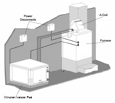
6 TYPICAL INSTALLATIONS Power Disconnects Air Handler Vibration Isolator Pad Fig. 5 - Typical Split with Air Handler Installation Power Disconnects Vibration Isolator Pad Fig. 6 - Typical Split with A -coil & Furnace Installation 6
7 MATCHED SYSTEM The GZ geothermal splits have been tested and rated with Carrier & Bryant air handlers (fan coils) and evaporator coils (for use with furnaces). Use air handler or cased coil from the list below and follow the Installation Instructions for those components. Geothermal and Air Handler or Cased Coil Match---Up Geothermal Split Air Handler Cased Coil GZ024 F(E/V)4***003, FB*024 C(A/N)P(V/M)P2417 GZ036 F(E/V)4***003, F(E/V)4***005 C(A/N)P(V/M)P3617 GZ048 F(E/V)4***005 C(A/N)P(V/M)P4821 GZ060 F(E/V)4***006 C(A/N)P(V/M)P6024 GZ072 F(E/V)4***006 C(A/N)P(V/M)P6024 When using the GZ unit with a furnace, it is important to match the CFM output of the furnace to the requirements of the GHP. For the GZ072, the selected furnace must achieve at least 2200 CFM. NOTE: The Infinity/Evolution Control may not prevent the system from accepting a furnace with less airflow than required for the GZ072. This is the responsibility of the installer. REFRIGERANT LINES! WARNING PERSONAL INJURY / ENVIRONMENTAL HAZARD Failure to follow this warning could result in personal injury or death. Relieve pressure and recover all refrigerant before system repair or final unit disposal. Use all service ports and open all flow control devices, including solenoid valves.! CAUTION ENVIRONMENTAL HAZARD Failure to follow this caution may result in environmental damage. Federal regulations require that you do not vent refrigerant to the atmosphere. Recover during system repair or final unit disposal. The installation of the copper refrigerant tubing must be done with care to obtain reliable, trouble free operation. This installation should only be performed by qualified refrigeration service and installation personnel. Refrigerant lines should be routed and supported so as to prevent the transmission of vibrations into the building structure. 75 feet as the maximum length of interconnecting refrigerant lines in split system heat pumps. Beyond 75 feet, system losses become substantial and the total refrigerant charge required can compromise the reliability and design life of the equipment. Refrigerant lines should be sized in accordance with those listed in Table 3. Copper tubing must be clean and free of moisture and dirt or debris. The suction and liquid lines should be insulated with at least 3/8 wall, closed -cell foam rubber insulation or equivalent. Table 3 Valve Sizing Chart Valve Sizing Chart Unit Size Line Type Valve Conn. Size Allen Wrench Size GZ024, 036 Suction 3/4 5/16 GZ048, 060, 072 Suction 7/8 5/16 All Valves Liquid 3/8 5/16 Some points to consider are: S drop (friction losses) in refrigerant suction lines reduces system capacity and increases power consumption by as much as 2% or more, depending on the line length, number of bends, etc. drop in liquid lines affects system performance to a lesser degree, provided that a solid column of liquid (no flash gas) is being delivered to the refrigerant metering device, and that the liquid pressure at the refrigerant metering device is sufficient to produce the required refrigerant flow. S Oil is continually being circulated with the refrigerant so, oil return to the compressor is always a consideration in line sizing. Suction lines on split system heat pumps are also hot gas lines in the heating mode, but are treated as suction lines for sizing purposes. If the recommended suction lines sizes are used, there should be no problem with oil return. S Vertical lines should be kept to a minimum. Vertical liquid lines will have a vertical liquid lift in either heating or cooling, and the weight of the liquid head is added to the friction loss to arrive at the total line pressure drop. S Wherever possible, the air handler should be installed at a higher elevation than the condensing section to aid with oil return to the compressor. Linear vs Equivalent Line Length Linear Line Length - is the actual measured length of the line including bends. This is used to calculate the additional refrigerant charge that must be added to the system. Equivalent Line Length - is the combination of the actual length of all the straight runs and the equivalent length of all bends valves and fittings in a particular line. The equivalent length of a bend, valve or fitting is equal to the length of a straight tube of the same diameter having the same pressure drop as the particular valve or fitting. The ASHRAE Fundamentals Handbook provides tables for determining the equivalent length of various bends, valves and fittings. Connecting Refrigerant Lines S Use only ACR grade copper tubing and keep ends sealed until joints are made. S For best performance, select routing of refrigerant lines for minimum distance and least number of bends. S Size lines in accordance with Table 5. S Cut crimped ends off the air handler suction and liquid lines. Connect and braze lines to the air handler. NOTE: The air handler is factory supplied with a holding charge of dry nitrogen. S Connect and braze lines to service valves on the condensing section.! CAUTION UNIT DAMAGE HAZARD Failure to follow this caution may result in equipment damage or improper operation. S Use a brazing shield S Wrap service valves with wet cloth or heat sink material. S Direct flame away from the valve body. S Valve body temperature must remain below 250_F to protect the internal rubber O rings and seals. S Use nitrogen purge while brazing. Pressurize the refrigerant lineset and air handler to 150 lbs with dry nitrogen through the ports provided on the self service valves. Check lineset and unit connections for leaks. Once system integrity is verified, evacuate lineset and air handler with a good vacuum pump to 500 microns and hold for half hour. IMPORTANT: Pumpdown must never be used with heat pumps. 7
8 After verifying system integrity, slowly open service valve to allow refrigerant to flow through system. Unit is pre-charged for 25 of line set. Refer to Tables 4, 5 and 6 to adjust and verify system charge accordingly. Table 4 Liquid Line Charge per Linear Ft. Liquid Line Charge per Linear Ft. Liquid Line Size O.D. R410A oz per ft. 1/4.25 5/ /8.60 1/ / Table 5 Refrigerant Charge, Line Sizing & Capacity Multipliers Refrigerant Charge, Line Sizing and Capacity Multiplier Chart Refrigerant Line O.D. Size (Based on Equivalent Line Length) Model Factory R410A Suction/Discharge 25 Ft. 35 Ft. 45 Ft. 50 Ft. 75 Ft. Charge (oz)* Vapor Line LIQ. SUC LIQ. SUC LIQ. SUC LIQ. SUC LIQ. SUC GZ /8 3/4 3/8 3/4 3/8 3/4 3/8 3/4 3/8 7/8 3/4 GZ /8 3/4 3/8 3/4 3/8 3/4 3/8 7/8 3/8 7/8 3/4 GZ /8 7/8 3/8 7/8 3/8 7/8 3/8 7/8 3/8 7/8 7/8 GZ / /8 3/ /8 3/ /8 3/ /8 3/ /8 7/8 GZ / /8 3/ /8 3/ /8 3/ /8 3/ /8 7/8 CAPACITY MULTIPLIER Example 1: Example 2: Model GZ036 with 45 ft. of equivalent length of 3//8 O.D. Liquid Line. Total system charge = Factory charge + (45 ft ft) X.60 oz/ft. Total system charge = 86 oz + (20 ft x.60 oz/ft) = 98 oz. Additional 12 oz of R410A refrigerant required. Model GZ060 with 10 ft. of equivalent length of 3//8 O.D. Liquid Line. Total system charge = Factory charge + (10 ft ft) X.60 oz/ft. Total system charge =115 oz --- (15 ft x.60 oz/ft) = 106 oz. Reduce charge 9 oz of R410A refrigerant is required. Line Set Limitations: A 20 ft. Differential is the recommended limit without special considerations. For installations with ft. Differential, it is recommended to add a liquid line solenoid and, if the fan coil or furnace is above the GZ unit, add an inverted trap before line drop. Unit CNPV2417 FV4CNF003 FE4CNF003 Table 6 Charge Adjustments When Paired with Air Handlers Charge Adjustments for GZ condensing section when paired with air handlers (oz) FB4CMF024 CNPVP3617 FV4CNF003 FE4CNF003 CNPVP4821 FV4CNF005L FE4CNF00FL CNPVP6024 FV4CNF006 FE4CNF006 GZ GZ GZ GZ GZ Example: Model GZ048 condensing section paired with FV4CNF005L air handler with 45ft of equivalent length of 3/8 O.D liquid Line. Total system charge = factory charge + (charge adjustments for air handler)+ (45ft ft) x.60 oz/ft. Total system charge = 88 oz + (5 oz ) + (20ft x.60 oz/ft) = 105 oz. Additional 17 oz of R410A refrigerant required. 8


9 WATER PIPING Supply and return piping must be as large as the unit connections on the heat pump (larger on long runs).! CAUTION UNIT OPERATION HAZARD Failure to follow this caution may result in improper equipment operation. Never use flexible hoses of a smaller inside diameter than that of the fluid connections on the unit. GZ units are supplied with either a copper or optional cupronickel water coax coil. Copper is adequate for ground water that is not high in mineral content. NOTE: Proper testing is recommended to assure the well water quality is suitable for use with water source equipment. When in doubt, use cupronickel. See Application Considerations notes on page 4. In conditions anticipating moderate scale formation or in brackish water, a cupronickel heat exchanger is recommended. Both the supply and discharge water lines will sweat if subjected to low water temperature. These lines should be insulated to prevent damage from condensation. All manual flow valves used in the system must be ball valves. Globe and gate valves must not be used due to high pressure drop and poor throttling characteristics.! CAUTION EQUIPMENT DAMAGE AND/OR UNIT OPERATION HAZARD Failure to follow this caution may result in equipment damage and/or improper operation. Never exceed the recommended water flow rates as serious damage or erosion of the water-to -refrigerant heat exchanger could occur. Always check carefully for water leaks and repair appropriately. Units are equipped with female pipe thread fittings. NOTE: Teflon tape sealer should be used when connecting water piping connections to the units to insure against leaks and possible heat exchanger fouling. NOTE: The unit is shipped with water connection O -rings. A 10 pack of O -rings (part #4026) can be ordered through Replacement Components Division (RCD). IMPORTANT: Do not over -tighten connections. Flexible hoses should be used between the unit and the rigid system to avoid possible vibration. Ball valves should be installed in the supply and return lines for unit isolation and unit water flow balancing (on open -loop systems). Loop Pump Connections Refer to the flow center installation manual for piping and wiring instructions. When using a flow center containing a variable speed pump, kit #4129 is required. Solenoid Valves Open loop well water applications require a water solenoid valve. The purpose of the valve is to allow water to flow through the GHP only during operation. For ground water/open loop installations, solenoid valves MVBR3F and MVBR4F are recommended due to its fast opening/slow closing timing feature (see Fig. 7). This valve will open in approximately 5 seconds. Solenoid valves that are slow opening are not recommended as water in the unit s coax may freeze during start -up of a heating call. A frozen coax is not covered under warranty. MVBR3 and MVBR4F valves are also slow closing to eliminate potential water hammer. Information on the MVBR3F and MVBR4F valves is shown below. Part Number MVBR3F MVBR3F Flow Regulator Valves Fig. 7 - Solenoid Valves A Table 7 Solenoid Valves Description Valve, motorized solenoid, forged brass ¾ FPT, 24V Valve, motorized solenoid, forged brass 1 FPT, 24V A flow regulator valve should be used in open loop / well water applications to set the flow rate through the heat pump. The lowest entering fluid temperature (EWT) expected should be used to determine the flow rate per ton. 1.5 GPM per ton is acceptable for 50_F (10_C) EWT or higher. 2 GPM per ton should be used if EWT is below 50_F (10_C).(SeeFig.8andTable8) Part Number FR2 FR3 FR4 FR5 FR6 FR7 Fig. 8 - Flow Regulator Table 8 Flow Regulators Flow Regulator Valves Valve, flow regulator, 3/4 FPT x 3/4 FPT, 2 GPM Valve, flow regulator, 3/4 FPT x 3/4 FPT, 3 GPM Valve, flow regulator, 3/4 FPT x 3/4 FPT, 4 GPM Valve, flow regulator, 3/4 FPT x 3/4 FPT, 5 GPM Valve, flow regulator, 3/4 FPT x 3/4 FPT, 6 GPM Valve, flow regulator, 3/4 FPT x 3/4 FPT, 7 GPM A
 is recommended to help reduce water hammer.")
10 Typical Open Loop Piping Open loop systems require a water solenoid valve to turn on the water when the heat pump compressor is energized, and to turn off the water when the compressor is off. A slow -closing motorized valve (MVBR3F or MVBR4F) is recommended to help reduce water hammer. A flow regulator limits water flow to avoid using more water than the heat pump requires, which wastes water and increases pumping costs. A hose kit provides vibration isolation, as well as convenient fittings to install P/T (pressure/temperature) plugs for checking water temperature and pressure drop at start-up and during troubleshooting. Fig. 9 shows the typical piping arrangement for a single solenoid valve. For single speed heat pumps and smaller two -stage heat pumps (3 tons and smaller), one valve is typical. For larger two -stage heat pumps, there is an opportunity to save a significant amount of energy (and avoid wasting water) with the use of two solenoid valves, one for first stage, and both for second stage (Fig. 10). Heat Pump MVBR Solenoid Valve Flow Regulator MVBR4F solenoid valve 1 rubber hose* P/T Plug* Heat Pump Elbow* LWT 1 hose barb x 1 MPT* 1 MPT x 3/4 MPT 1 ball valve Piping to discharge*** Tank EWT 1 hose barb x 1 MPT* 1 ball valve (optional) * Part of HK4MM hose kit ** *** Consult local regulations for discharge requirements Consider variable speed pump in place of pressure tank and pressure switch Submersible Pump Fig. 9 - Single Solenoid Valve Solenoid Valve Stage One Flow Regulator Stage One Ball Valve From Heat Pump Solenoid Valve Stage Two Flow Regulator Stage Two NOTE: Refer to Fig. 18. Wiring kit #4129 is recommended for easy 24 volt connection staging solenoids with compressor. Fig Two Solenoid Valves 10
11 HRP Piping All hot water piping MUST be a minimum of 5/8 O.D. copper tube to a maximum distance of 15 feet. For distances beyond 15 feet, but not exceeding 60 feet, use 1/2 copper tube. Separately insulate all exposed surface of both connecting water lines with 3/8 wall closed cell insulation. Install isolation valves on supply and return to the heat recovery. (See Fig. 11) Tank Preparation 1. Turn off electrical or fuel supply to the water heater. 2. Attach garden hose to water tank drain connection and run other end of hose out doors or to an open drain. 3. Close cold water inlet valve to water heater tank. 4. Drain tank by opening drain valve on the bottom of the tank, then open pressure relief valve or hot water faucet. 5. Once drained the tank should be flushed with cold water until the water leaving the drain hose is clear and free of sediment. 6. Close all valves and remove the drain hose. 7. Install HR water piping. Tank Refill 1. Open the cold water supply to the tank. 2. Open a hot water faucet to vent air from the system until water flows from the faucet, then close. 3. Depress the hot water tank pressure relief valve handle to ensure there is no air remaining in the tank. 4. Carefully inspect all plumbing for water leaks. Correct as required. 5. Using the air bleed valve, purge all air from water piping, allowing all air to bleed out until water appears at valve. 6. Before restoring the power or fuel supply to the water heater, adjust the temperature setting on the tank thermostat(s) to ensure maximum utilization of heat available from the refrigeration system and to conserve the most energy. On tanks with thermostats and both upper and lower elements, the lower element should be turned down to 100_F, while the upper element should be adjusted to 120_F. Depending upon the specific needs of the customer, you may need to adjust the upper element differently. On tanks with a single thermostat, lower the thermostat setting to 120_F or the LOW position. After thermostat adjustments are completed, replace access cover and restore electrical or fuel supply to water heater. IMPORTANT: Copper should be used for piping from HRP to domestic water tank(s). Use 5/8 (16mm) O.D. copper or larger. Refer to local codes for hot water piping. Insulate the water lines between the GHP and the water heater with a minimum of 3/8 (10mm) closed cell insulation. One Tank System Hot Out Domestic Cold Supply Air Bleed Valve Shut-off Ball Valve HP Heater (w/active elements) Domestic Hot Supply Hot Out Two Tank System (preferred) Domestic Cold Supply Air Bleed Valve Cold In Shut-off Ball Valve HP Heater (w/active elements) Heater (no active elements pre-heat tank) Package unit shown. GZ split unit arrangement similar with different water locations on unit. Fig HRP Piping 11 A150174
12 ELECTRONIC THERMOSTAT INSTALLATION Field Connections This section is intended as a quick reference only and should not replace a complete review of thermostat Installation Instructions. The GZ unit can be installed as communicating or non -communicating with UI communicating or standard non -communicating thermostats. Match User Interface (UI) to GZ Standard 2---stage Thermostat to GZ FE Yes No Communicating Yes Yes Furnace Non---communicating No Yes Fan Coil Non---communicating No Yes Furnace NOTE: Matching geothermal systems with non -communicating indoor models will not offer full communicating functions from the UI. Communicating User Interface (UI) is designed to self-program with the GZ unit when connected to the ABCD connector on the UPM board. Only two (2) wires are needed from the UI for the AB connections since the GZ unit has a transformer for the 24v (see Fig. 12 and 13). NOTE: It is always a good idea to run extra thermostat wires during installation in the event of faulty wires, etc. Communicating System Tips: S The GZ units include an Outdoor Air erature (OAT) sensor in the literature packaging. Refer to Table 9 for thermostats that can incorporate this OAT and the thermostat instructions for wiring. S The GZ unit must be used with Wall Control version 13 or newer software for communicating connections. S Energy tracking is not available for the geothermal products at this time for the Wall Control V13 software. However, future UI software versions will have this feature. S Wi -Fi capability will be available with the Wi -Fi Wall Controls SYSTXCCITC01, SYSTXCCITW01, SYSTXBBECC01, SYSTXBBECW01. S To enter the Wall Control service mode hold the service cap in the main menu for about 10 seconds until it turns green then release. S The last 10 system faults can be found in the service screens. Flash codes on the UPM board flash only an active code with series of short and long flashes on the amber LED. A code 37 will appear on the UPM LED as 3 short flashes followed by a pause then 7 long flashes followed by another pause and repeats this series. The Wall Control will display text on the screen for the last 10 events. S Exit service screens by selecting Done. Non -Communicating On non -communicating system, the two -stage control receives 24VAC low -voltage control system inputs through the Y1, Y2, and O connections located at the bottom of the control board (see Fig. 14.) On a non -communicating system, output W1 is connected to the control board for auxiliary heat. For Non -communicating, any standard multi-stage HP (3 heat, 2 cool) thermostat is acceptable. Non -communicating will not have full features. Refer to Table 9 for the recommended communicating and non -communicating thermostats. Communicating System Wall Control A B C D S1 S2 Communicating System Wall Control & Smart Sensor(s) A B C D Green - Data A Yellow - Data B White - COM Red - 24VAC Optional Remote Room Sensor Humidifier Connection Communicating Variable-Speed Furnace / Fan Coil A B C D HUM COM 24V OAT Green Yellow ABCD Connections OAT Sensor (Optional) Fig Universal Two -Wire Connection A B C D A B C D Damper Control module Green Yellow White Red Humidifier Connection Communicating Indoor Unit A B C D HUM COM 24V OAT Communicating HP A B C D A B C D OAT Sensor (Optional) A Communicating HP A Fig Zoning Connection for Communicating Indoor Unit with 2 -Stage Communicating split geothermal unit Thermostat R G Y1 Y2 C O Non-Communicating Furnace / Fan Coil R G Y1 Y2 C O FV/FE Only (not required for furnace application A Fig Connection for Non -comm. Furnace / Fan Coil Table 9 Recommended Thermostats Carrier Systems: Bryant Systems: Infinityr Touch Wall Control Evolutionr Connex Wall Control SYSTXCCITC01* SYSTXBBECC01* SYSTXCCITW01* SYSTXBBECW01* SYSTXCCITN01* SYSTXBBECN01* Performance Series Preferred Series TP --- PRH01 T6 --- PRH TP --- NRH01 T6 --- NRH TP---PHP01 T6 --- PHP Corr Wi --- Fi Thermostat Housewiser Wi---Fi Thermostat { TP --- WEM01 { T6 --- WEM01 * Version 13 or later software { No OAT sensor connection. The OAT is retrieved from the Internet. The GZ unit is shipped with one OAT sensor TSTATXXSEN01---B Note: Any of the model numbers above may be followed by a revision letter such as ---A. HP Y1 Y2 C O 12
13 ELECTRICAL Refer to electrical component box layout. See Fig. 15.! CAUTION UNIT OPERATION HAZARD Failure to follow this caution may result in equipment damage and/or improper operation. S Field wiring must comply with local and national electrical codes. S Power to the unit must be within the operating voltage range indicated on the unit nameplate or on the performance data sheet. S Operation of unit on improper line voltage or with excessive phase imbalance will be hazardous to the unit, constitutes abuse, and may void the warranty. Properly sized fuses or HACR circuit breakers must be installed for branch circuit protection. See unit nameplate for maximum fuse or breaker size. NOTE: Use copper wire only between disconnect switch and unit. The unit is provided with a concentric knock -out for attaching common trade sizes of conduit, route power supply wiring through this opening. Always connect the ground lead to the grounding lug provided in the control box and power leads to the line side of compressor contactor as indicated on the wiring diagrams. Utility Curtailment Utility curtailment is a voluntary energy saving program offered through utility companies in some locations. Utility company will provide the equipment that allows them to cut back demand on equipment during peak demand times. A qualified HVAC technician should install the device to ensure system compatibility. Refer to Fig. 16 for typical wiring to the UPM. Systems using communicating user interface controls will set up the control by entering the service screens, Setup and then select Utility Curtailment. There will be 3 options to enable or disable the curtailment: 1. Disabled: the utility curtailment, if wired into the UPM, will be ignored. 2. *Low Stage: when utility curtailment relay opens, the unit will only operate at low -stage. 3. *Off: when utility curtailment relay opens, the unit will shut down until the utility relay closes. * There will be a brief delay to cause the unit to stage or shut down (approximately 0.40 to 1.20 minutes can be expected). UPM CONTROL BOARD RUN CAPACITOR GROUNDING LUG CONTACTOR: 2 POLE 2 THROW TRANSFORMER: 208/230 75VA A14180 Fig Electrical Component Box Layout The electrical box is designed to allow servicing behind the box relatively easily to access reversing valve, etc. The 2-3 screws on the bottom of the electrical box could be removed and with wiring all out one side of the box carefully swing box in direction of the wiring bundle to allow access to components behind the box if necessary. Remember that all sides of the cabinet are accessible but in event the unit is placed where all sides make this difficult, removal of the box may help. The transformer is a 75va transformer which should provide ample power for accessories. Size loads properly so they do not exceed capability of the transformer. The transformer allows 208/230V selection with the factory default of 230V. The transformer has a 5amp circuit breaker internally built in for class 2 rating. The circuit board has a 3 amp fuse that should identify any issues before the 5 amp circuit breaker trips. In an unlikely event of the transformer 5 amp circuit breaker tripping, it has a manual reset. UTILITY RELAY * UTILITY SIGNAL OPEN RELAY * SUPPLIED BY UTILITY PROVIDER Fig Utility Curtailment Wiring A
 that delays the compressor from starting after receiving a call from the thermostat to provide time for the valve to fully open.")

14 UPM Circuit Board Communicating controls notes: 1. The UPM board includes a delay at terminal Y1 (connector ST1) that delays the compressor from starting after receiving a call from the thermostat to provide time for the valve to fully open. Therefore, the end switch is not used for communicating controls. 2. For systems with two valves, see Fig. 18. C W/Y END SWITCH MVBR3F or MVBR4F NOTE: Optional wiring if wiring kit #4129 is not used. Fig Solenoid Valve Wiring A IMPORTANT: Ensure that wire colors match up From PL5 ext. harness Brown Yellow From PL5 ext. harness Brown Gray harness (brown to brown, blue to blue, black to black. C W/Y END SWIT CH MVBR3F or MVBR4F VALVE #1 C W/Y END SWIT CH MVBR3F or MVBR4F VALVE #2 To CC and Y2S Brown C at valve #1 & 2 W/Y at valve #1 Yellow UPM Circuit Board Existing female plug 4129 Extension Harness Gray W/Y at valve #2 IMPORTANT Communicating controls notes: 1. Y2 (connector ST1) is used for a utility curtailment input, and is not available for use as an output for the second valve. However, the wiring harness extension (part # 4129) used for variable speed flow centers (closed loop applications) provides a second stage connection as shown above (gray/brown wires). The wiring kit should be used for systems with two solenoid valves (yellow wire for stage 1, gray wire for stage 2, brown wire for common to both valves). Transformer Sizing Each MVBR3F/MVBR4F valve may use up to 11.5 VA. Verify heat pump installation manual to ensure that heat pump transformer is large enough for heat pump controls, water solenoid valve(s), and any other accessories. Other water solenoid valves Fig Two Solenoid Valve Wiring A The UPM board delays the compressor from starting after receiving a call from the thermostat to provide time for the valve to fully open. Therefore, the end switch is not used for communicating controls. may have higher VA requirements than the MVBR3F and MVBR4F valves 14
15 FACTORY INSTALLED FEATURES A number of factory installed options are available on the GZ Series of Heat Pumps. The following details the purpose, function and components of each option. Heat Recovery Package (HRP) (optional) The heat recovery package is a factory installed option on GZ series heat pumps. The HRP can be used to heat potable water during unit operation using waste heat from the compressor discharge gas. In some cases the HRP can provide most or all of the hot water requirements for a typical home. The HRP consists of three major components: 1. Double wall, vented refrigerant to water heat exchanger 2. Circulating pump 3. Control circuit The heat exchanger is rated for use with potable water and is acceptable for use as a domestic water heating device in most building codes. The pump circulates water between the domestic hot water tank and HRP heat exchanger in the Heat Pump. The control circuit ensures that the HRP only operates when there is available heat from the compressor and when the water is within a safe temperature range of below 140_F. When the heat pump compressor operates, the HRP will monitor the temperature of the discharge gas from the compressor. Once discharge gas is hot enough to provide useful heat to the domestic water tank, the circulating pump will be enabled, drawing water from the tank, through the HRP heat exchanger and then depositing the heated water back into the tank. If the water temperature reaches 140_F, the circulating pump is disabled to prevent over heating of the domestic water. The HRP is provided with an on/off switch in case the end user desires that the HRP be inactivated (typically during the winter months when space heating is most important). The circulating pump is enabled when compressor discharge temperature reaches 120_F (48.9_C). The circulating pump is disabled if an overload condition exists (over 1.35 amps).! CAUTION UNIT DAMAGE AND/OR OPERATION HAZARD Failure to follow this caution may result in unit damage and/or improper equipment operation. If heat recovery unit is installed in an area where freezing may occur, the unit must be drained during winter months to prevent heat exchanger damage. Heat exchanger ruptures that occur due to freezing will void the heat recovery package warranty along with the heat pump warranty.! CAUTION UNIT DAMAGE AND/OR OPERATION HAZARD Failure to follow this caution may result in unit damage and/or improper equipment operation. Do not apply additional controlled devices to the control circuit power supply without consulting the factory. Doing so may void equipment warranties. FIELD INSTALLED ACCESSORIES Liquid Line Solenoid Accessory Experience and good design practice dictate 75 feet as the maximum practical length for interconnecting refrigerant lines in split system heat pumps without special considerations. Beyond 75 feet, system losses become substantial and the total refrigerant charge required can compromise the reliability and design life of the equipment. Local codes or installation may suggest a liquid line solenoid, installation of long line solenoid should adhere to valve installation instructions. Accessory Liquid Solenoid with Communicating System Wall Control: When using the Wall Control, the liquid -line solenoid output is provided at the Y1 connection. Connect the solenoid as shown in Fig. 19. This is a 24VAC output that is energized whenever the compressor is energized. In compressor OFF mode, it closes to prevent refrigerant migration into the unit through the liquid -line. Systems with Accessory Liquid Solenoid Using a Non -Communicating Thermostat: The liquid solenoid is connected to the Y1 and C terminal connections (see Fig. 19) and assumes that both Y2 and Y1 are energized by the thermostat during call for high stage operation. In compressor OFF mode, the liquid solenoid closes to prevent refrigerant migration into the unit through the liquid -line. The terminal connections for Y1 and C will have LLS and the stat wires sharing the same connection points. C W/Y LLS & Solenoid NOTE: Optional wiring if wiring kit #4129 is not used. Fig LLS and Solenoid Connections A

16 Outdoor Air erature Sensor (OAT) An optional outdoor air temperature (OAT) sensor is provided in the literature package. Install the sensor outdoors, typically on the north side of the residence away from direct sunlight. Sensor package includes an adhesive holder for the sensor. See Fig 20 for wiring the sensor to the OAT plug on the fan coil or furnace unit control board. Do not connect to the optional remote sensor terminals (S1, S2) on the UI. Humidity control uses the OAT to adjust humidity target when the OAT drops into the cold range to prevent forming of condensation on windows. It also allows the UI to display outdoor air temperature. Compressor Start Accessories In the event of the rare occurrence of compressor starting issues such as dimming of the residential lights. Verify and correct voltage issues and add hard start components. Table 10 lists Hard Start components that are recommended in areas of poor power conditions. Fig OAT Sensor Connection A Table 10 Recommended Hard Start Kits Unit Size Compressor Hard Start Kit Start Cap Start MFD Start Cap Volts Start Relay GZ024 ZPS20K5E---PFV KSAHS2501AAA HC95DE HN61HB540 GZ036 ZPS30K5E---PFV KSAHS2501AAA HC95DE HN61HB540 GZ048 ZPS40K5E---PFV KSAHS2801AAA HC95DE HN61HB553 GZ060 ZPS51K5E---PFV KSAHS2801AAA HC95DE HN61HB553 GZ072 ZPS60K5E---PFV N/A HN61HB553 16
17 PRE START -UP CHECKLIST! CAUTION UNIT DAMAGE AND/OR OPERATION HAZARD Failure to follow this caution may result in unit damage and/or improper equipment operation. Equipment should never be used during construction due to likelihood of wall board dust accumulation in the air coil of the equipment which permanently affects the performance and may shorten the life of the equipment.! CAUTION UNIT DAMAGE AND/OR OPERATION HAZARD Failure to follow this caution may result in unit damage and/or improper equipment operation. Check with all code authorities on requirements involving condensate disposal/overflow protection criteria. jensure the isolation valves are open and water control valves are wired. jloop/water piping is complete and flushed, (clean and purged of air). jverify loop water chemistry meets requirements on water chemistry table (reference table 1) jantifreeze is added if necessary jverify HRP switch is energized, if applicable. Recommend de -energize if installed and water not available. jverify the HRP system is purged and connected completely, if applicable. jverify the freeze protection is set according to proper freeze temperature (26 or 15_ F) jremove access panels to access applicable compartments. jverify sufficient space is available for accessing and servicing areas such as the blower and electric heat compartment and the compressor and electrical control box compartment. jverify all supply voltage is in accordance with unit nameplate. jverify all wiring is tight and secure. jcheck that the unit blower is free to rotate and wheel is secure to shaft. jverify the condensate drain pan is clear and drains with proper external trap and pipe pitch. jensure the system air filters are installed. jensure no wiring is pinched when panels are re-installed. jverify loop pump wiring, if applicable, is in accordance with the pump installation instructions. jverify all system accessories and components are wired per applicable instructions and all wiring in accordance with NEC. jif non -communicating thermostat ensure the UPM dip switch settings are configured accordingly for Freeze Protection, Lockout trip setting and Brownout). UPM dip switch settings can be configured in the User Interface during set up (see steps below in user interface quick setup). jensure all panels are in place before powering up the unit. jalways check incoming line voltage, power supply and secondary control voltage for adequacy. Transformer primaries are dual tapped for 208 and 230 volts. Connect the appropriate tap to ensure a minimum of 18 volts secondary control voltage. 24 volts is ideal for best operation. jthe following guidelines are recommended for wiring between a thermostat and the unit: 18 GA up to 60 ft (18.3m), 16 GA up to 100 ft. (30.5m), and 14 GA up to 140 ft. (42.7m). UNIT START -UP If the unit utilizes the Communicating User Interface, reference information in the User Interface Quick Setup section. Non -communicating thermostats: jset the thermostat to the highest setting. jset the thermostat system switch to COOL, and the fan switch to the AUTO position. The reversing valve solenoid should energize. The compressor and fan should not run. jreduce the thermostat setting approximately 5 degrees below room temperature. jverify the heat of rejection is within 10% of the product data for conditions the unit is started under in cooling mode. jturn the thermostat system switch to the OFF position. The unit should stop running and the reversing valve should de-energize. jleave the unit off for approximately five (5) minutes to allow for system equalization. jturn the thermostat to the lowest setting. jset the thermostat switch to HEAT. jincrease the thermostat setting approximately five (5) degrees above room temperature. jverify the unit heat of extraction is within 10% of the unit product data information when started in the heating mode of operation. jset the thermostat to maintain desired space temperature. jcheck for vibrations, leaks, etc. jit is suggested that a start up / commissioning form be completed for each new installation. This document should be kept at both the job site and with the project folder of the installing contractor if needed to refer back to. USER INTERFACE QUICK SET -UP Install only approved thermostats per the unit Product Data. Communicating geothermal units require UI software version 13 or later. Read and Understand the thermostat Installation Instructions, this start -up is not intended to replace the thermostat Installation Instructions. Install each component per unit Installation Instruction. Wire each accordingly. Enter the service and installation screens in the UI Upon powering up the system, the user interface installation will seek out the control boards in the unit and recognize the unit model and size and communicating electric heat, if installed. Component search order: S Indoor (ECM is the indoor if GC model) S Outdoor (UPM) S SAM if applicable S Zoning if applicable S Any non -com components via selectable screens. Run set up to select specific features desired such as UPM switch settings (brownout, lockout and freeze protection). 17
18 UI SYSTEM INITIAL POWER UP AND CHECKOUT! WARNING ELECTRICAL SHOCK HAZARD Failure to follow this warning could result in personal injury or death. Ensure cabinet and electrical box are properly grounded j From the UI main screen select menu. Then find and select the service cap icon. Touch and hold the icon for about 10 seconds until it turns hat green then release to enter the screen that provides these options: S Equipment summary S Installation S Setup S Checkout j Select Installation to initialize equipment set up and follow screen prompts as necessary. j Verify equipment summary is correct and complete by selecting equipment summary. j Select Setup option to select system settings such as brownout protection, lock out settings and freeze protection. Set up air flow settings in the Setup option. Follow on screen prompts for airflow options. j Airflow verification test can be achieved from the installation and service screen after full installation. Cooling Airflows: S Quiet: lowest airflow (~300CFM pr ton) S Comfort: Default (varied on temp/humidity) S Efficiency: (1 and 2) (fixed and no dehum) S Max: (~400 CFM pr ton) (no dehum) Heating Airflows: S Comfort: Default (varied on temp/humidity) S Efficiency: (1 and 2) (fixed and no dehum) S Max: (~400 CFM pr ton) (no dehum) Check out mode can now be accessed to check out cooling or heating modes for up to 120 minutes and can be stopped at any time. j Verify low cool j Verify high cool j Verify low heat j Verify high heat j Verify Electric Heat Operation in emergency and auxiliary heat mode if applicable j Conduct System Verification per the section below and the start -up checklist. j Set up the thermostat for normal operation, set up customer preferences for programming j Check for vibration, leaks, etc. j Make sure company logo and contact info has been added to UI. j Explain thermostat operation and maintenance to the homeowner. SYSTEM VERIFICATION (COMMUNICATING & NON-COMMUNICATING) j The unit is shipped with a Unit Start-up Checklist in the literature package. Allow the unit to operate for minimum of 5 minutes between system changes to stabilize before checking system performance. NOTE: It is not recommended to access the refrigerant system at start up on package units. Access should only be necessary as last resort in troubleshooting to prevent unnecessary charge issues. j Check the water flow and operating conditions. Reference Table 10. NOTE: Tables typically show 3 GPM rates for each unit size. Rates are described from top to bottom listed as: Top listed GPM: minimum suggested for open loop. Middle listed GPM: minimum suggested for closed loop. Bottom listed GPM: Suggested rate for closed loop. j Verify the unit is operating within 10% of the Heat of Extraction (HE)/Heat of Rejection (HR) published in the unit Product DataPerformancetables. Access Product Dataon HVAC Partners. a. HE/HR= GPM x TD x Fluid Factor (500 for water, 485 for antifreeze). b. Utilize Ht. Abs Btu/hr in heating mode for capacity. c. Utilize Ht. Rej Btu/hr in cooling mode for capacity. j Record all data on the Startup Checklist included in the unit packet. Save the checklist in the customer file at your dealership. Solenoid Valve Start-Up The first time the water solenoid valve is operated, it may require 30 to 45 seconds to power open. This time is to charge an internal capacitor. After the initial power up the valve will open in 5 seconds. If the line voltage power has been turned off for service of the unit, the system will go through the same first time power up sequence. The 24 VAC connections to the water solenoid valve should be made on the C and W/Y terminals. The power from the unit controls is identified as C and Y1. The same terminals are used if wiring in a liquid line solenoid. (See Fig. 19) Initial Start-Up of HRP! CAUTION UNIT DAMAGE AND/OR OPERATION HAZARD Failure to follow this caution may result in unit damage and/or improper equipment operation. Make sure all valves in heat recovery water piping system are open. NEVER OPERATE HR PUMP DRY. 1. Turn on the heat pump. The HR pump should not run if the compressor is not running. 2. Turn HR switch to the ON position. The pump will operate if entering water temperature to HR is below 140_F and compressor discharge temperature is 120_F or above. 3. The temperature difference between the water entering and leaving the heat recovery should be 5_F to15_f. 4. Allow the unit to operate for 20 to 30 minutes to ensure it is functioning properly. The pump should shut off when the water temperature entering the heat recovery reaches 140_F. 18
19 START YES Y1 = ON NO RESET ON Y NO RESET ON R R = 24VAC YES YES NO POWER/ SWITCHES/SENSOR STATUS CHECK CLEAR FAULTS V > 170VAC NO BLINK CODE ON STATUS LED SOFT LOCKOUT RECORD ALARM START COUNTER (IF APPLICABLE) COUNTER NEEDED? NO YES YES CNT = CNT+1 YES HPC = CLOSED LPC =CLOSED NO CC OUPUT= ON YES NO LOCKOUT CAN BE SET TO 4 VIA DIP SWITCH NO COUNT = 2 OR COUNT = 4 YES YES NO START TIMER TIME > 120 SEC NO YES BLINK CODE ON STATUS LED NO HARD LOCKOUT? YES FRZ >TEMP LIMIT YES NO START TIMER TIME > 30 SEC NO YES BLINK CODE ON STATUS LED DISPLAY OUTPUT = PULSE ALR OUTPUT = ON/PULSE CON > 0 NO CC OUTPUT = OFF YES START ANTI SHORT CYCLE NO INITIAL POWER UP YES NO START RANDOM START UP T>ASCOR CC RS SEC YES CC OUTPUT = ON Fig UPM Sequence of Operation (SOO) Flow Chart A
20 SYSTEM FUNCTIONS AND SEQUENCE OF OPERATION GZ models utilize either a Communicating Wall Control or a standard 2 -stage heat pump thermostat. With a call for first stage cooling/heating, the low stage is energized. If low -stage cannot satisfy the cooling/heating demand, high stage is energized by the second stage of indoor thermostat. After second stage is satisfied, the unit returns to low -stage operation until the first stage is satisfied or until second stage is required again. When both first and second stage cooling are satisfied, the compressor will shut off. When a 2 -stage unit is operating at low -stage, system vapor (suction) pressure will be higher than a standard single-stage system or high -stage system. Communicating Sequence: The UPM board controls all functions. See Fig. 22. Non -Communicating Sequence: The reversing valve is energized to cool. Cooling - The first stage of cooling powers Y1 and O. The second stage of cooling powers Y1, Y2 and O. Heating - The first stage of heating powers Y1, and the second stage of heating powers Y1 and Y2. Communication and Status Function Lights A green LED (COMM light) on the UPM (see Fig. 22) indicates successful communication with the other system products. The green LED will remain OFF until communication is established. Once a valid command is received, the green LED will turn ON continuously. If no communication is received within 2 minutes, the LED will be turned OFF until the next valid communication. Amber Status Light - An amber colored STATUS light is used to display the operation mode and fault codes as specified in the troubleshooting section. See Table 15 for codes and definitions. NOTE: Only one code will be displayed on the UPM board (the most recent, with the highest priority). Time Delays Unit time delays include: S Five minute time delay to start cooling or heating operation when there is a call from the thermostat or user interface. To bypass this feature, momentarily short and release Timer Speed -Up pins. S Five minute compressor re-cycle delay on return from a brown -out condition. S Two minute time delay to return to standby operation from last valid communication (with UI only). S There is no delay between staging from low to high and from high to low capacity. The compressor will change from low to high and from high to low capacity on the fly to meet the demand. Compressor Operation The basic scroll design has been modified with the addition of an internal unloading mechanism that opens a by -pass port in the first compression pocket, effectively reducing the displacement of the scroll. The opening and closing of the by -pass port is controlled by an internal electrically operated solenoid. The modulated scroll uses a single step of unloading to go from full capacity to approximately 67% capacity. A single speed, high efficiency motor continues to run while the scroll modulates between the two capacity steps. Modulation is achieved by venting a portion of the gas in the first suction pocket back to the low side of the compressor, thereby reducing the effective displacement of the compressor. Full capacity is achieved by blocking these vents, thus increasing the displacement to 100%. A DC solenoid in the compressor controlled by a rectified 24 volt AC signal in the external solenoid plug moves the slider ring that covers and uncovers these vents. The vent covers are arranged in such a manner that the compressor operates at approximately 67% capacity when the solenoid is not energized and 100% capacity when the solenoid is energized. The loading and unloading of the two step scroll is done on the fly without shutting off the motor between steps. NOTE: 67% compressor capacity translates to approximately 75% cooling or heating capacity at the indoor coil. The compressor will always start unloaded and stay unloaded for five seconds even when the thermostat is calling for high stage capacity. Safety Devices and UPM Board PL2 LPS Low pressure switch 11. CW1Y1Y20: Standard tstat connection 2. PL3 HPS: High pressure switch 12. J2 Speed Up Timer: Test jumper 3. SEC1 and SEC2: Transformer 13. S1: DIPSwitches 4. VS: Start circuit high volt. 14. PL8 Model: Model plug conn. 5. L2 and L1: Contactor and high voltage 15. PL6 FRZ1: coil freeze sensor 6. PWM1 and PWM2: N/A 16. PL6 OPT: N/A 7. F1: 3 amp fuse 17. PL1 RVS: Reversing valve plug 8. PL5: Compressor plug 18. LED1 COMM: Comm status light 9. PL7: ABCD comm. stat conn. 19. LED2 STATUS: Status and fault code light 10. COND: Condensateoverflow A Fig UPM Board The UPM Board includes the following features: S LOW PRESSURE SWITCH: The low pressure switch safety is designed to shut down the compressor in th event of loss of charge. Cut in 60 +/- 15 psig and cut out 40 +/- psig. S HIGH PRESSURE SWITCH: The high pressure switch safety is designed to shut down the compressor if it exceeds limits. Cut in 420 +/- 15 psig and cut out 600 +/- psig. Switch Protection: The split geothermal unit is equipped with high - and low -pressure switches. If the control senses the opening of a high - or low -pressure switch, it will respond as follows: 1. De-energize the compressor contactor. 2. Display the appropriate fault code (see Table 15). 3. After a 15 minute delay, if there is a call for cooling or heating and LPS or HPS is reset, the compressor contactor is energized. 4. If the open switch closes anytime after the 15 minute delay, then resume operation with a call for cooling or heating. 5. If LPS or HPS trips 2-4 consecutive cycles per the dip switch lockout setting or UI setting (Communicating only), the unit operation is locked out for 4 hours. 6. In the event of a high -pressure switch trip or high -pressure lockout, check the refrigerant charge, and the coax coil (in cooling) for water issues, or indoor airflow in heating. 7. In the event of a low -pressure switch trip or low -pressure lockout, check the refrigerant charge and indoor airflow (cooling) and coax coil water pressure and flow in heating. S LOW PRESSURE BYPASS TIMER: If the compressor is running and the low pressure switch opens, the board will keep the compressor ON for 120 seconds. After 2 minutes, if the low pressure switch remains open, the board will shut down the compressor and enter a soft lockout. The compressor will not be

21 energized until the low pressure switch closes and the anti-short cycle time delay expires. If the low pressure switch opens 2-4 times in 1 hour, the unit will enter a 4 hour lockout period. S ANTI-SHORT CYCLE TIMER: 5 minute delay on break timer to prevent compressor short cycling. S RANDOM START: Each board has a unique random start delay ranging from 30 to 270 seconds on initial power up to reduce the chance of multiple unit simultaneously starting at the same time after power up or after a power interruption, thus avoiding creating large electrical spike. S CONTROL FAULT: If the split geothermal unit control board has failed, the control will flash the appropriate fault code (see Table 15). The control board should be replaced. S UPM DIP SWITCH SETTINGS: The UPM has 3 features controlled on the dip switch. 1. Freeze Protection Limit for the Freeze one water coil. 2. Lockout Settings (Soft Lockouts) 3. Brownout (High voltage protection) DIP Switch Position DIP SWITCH ON OFF (Default) Freeze Protection SW1 15 F 26 F Limit SW2 SW3 Number of Trips to Lockout (HPS / LPS) Brownout 4 2 Brownout Protection is Disabled Brownout Protection is Active S FREEZE SENSOR: The water coil is protected by a thermistor located between the condensing water coil (coax) and the thermal expansion valve (see Fig. 9). The setting is default at 26_F (-3.33_C) but can be changed for units with ample anti -freeze to have a lower setting of 15 _F (-9.44_C) with the dip switch selection or UI setting. If the unit is employing an open loop system (no anti -freeze protection), the freeze limit trip for the UI will only allow selection of 26_F (-3.33_C) in order to shut down the unit at the appropriate leaving water temperature and protect the heat pump from freezing. If the refrigerant temperature drops below or remains at freezing limit trip for 30 seconds, the UPM will shut down the compressor and the board will flash fault code 86 (FRZ1 lockout). Fault code 86 will remain until the condition is corrected and also requires a manual reset low voltage circuit. After a manual reset and there is a call for heating, the unit will be re -energized automatically ONLY when the freeze sensor temperature is 7_F (-13.9_C) above setpoint (SW1). Fault code 57 is FRZ1 sensor fault, which means the sensor is invalid, meaning the sensor could be open or faulty. If the sensor is invalid or out of the range (the range is from -50_F to 150_F (-45.6_C to 65.6_C), the compressor will be de -energized and display the freeze sensor fault code (57). When the sensor goes back into range, freeze sensor fault code will clear and the system will start up automatically if a demand exists. For troubleshooting the Freeze Sensor, refer to Table 15. Fig Freeze Protection Sensor Location A14121! CAUTION UNIT DAMAGE AND/OR OPERATION HAZARD Failure to follow this caution may result in unit damage and/or improper equipment operation. If unit is employing a fresh water system (no anti -freeze protection), it is extremely important to have the Freeze1 set to the default 26_F (-3.33_C).! CAUTION UNIT DAMAGE AND/OR OPERATION HAZARD Failure to follow this caution may result in unit damage and/or improper equipment operation. Freeze sensor will not guard against the loss of water. A flow switch is recommended to prevent the unit from running if water flow is lost or reduced. S LOCKOUTS: If system protection faults occur, the unit will shut down the compressor and fault codes will be shown on the UPM board and the UI screen. There are two types of lockouts: Soft lockouts - This is a selectable dipswitch position to allow 2 or 4 unit trips before going to hard lockout. Hard lockouts - Will require a manual reset. This applies to all unit trips unless otherwise noted. In order to exit the hard lockout early for servicing, the low voltage power to the unit would need to be reset and the fault conditions corrected. NOTE: The blower motor will remain active during a lockout condition. S BROWNOUT PROTECTION: The compressor will be shut down if the incoming voltage falls below 170 VAC for 4 seconds and fault code will display on UPM LED and wall control (if applicable). The compressor will remain off until the voltage is above 173 VAC for at least 4 seconds and the anti-short cycle timer times out. Defeat the Brownout - The high voltage brownout feature can be defeated in the event of nuisance trips due to severe noisy power conditions. The UPM dip switch has brownout ON as default, to defeat the brown out protection, the selection can be changed to OFF. All efforts should be exhausted to correct any electrical deficiencies before defeating this safety feature to eliminate possible equipment damage. S COMPRESSOR VOLTAGE SENSING: If there is no 230V at the compressor contactor(s) when the indoor unit is powered and cooling or heating demand exists, the appropriate fault code is displayed. Verify the disconnect is closed and 230V wiring is connected to the unit. S 230V LINE (POWER DISCONNECT) DETECTION: The control board input terminals labeled VS and L2 (see Fig. 22) are used to detect compressor voltage status and alert the user of potential problems. The control continuously monitors the high voltage on the run capacitor of the compressor motor. Voltage should be present any time the compressor contactor is energized and voltage should not be present when the contactor is de -energized. S CONTACTOR SHORTED DETECTION: If there is compressor voltage sensed when there is no demand for compressor operation, the contactor may be stuck closed or there may be a wiring error. The control will flash the appropriate fault code. If the control senses the compressor voltage after start-up and is then absent for 10 consecutive seconds while cooling or heating demand exists, the thermal protector is open. The control de-energizes the compressor contactor for 15 minutes. The control Status LED will flash the appropriate code shown in Table 15. After 15 minutes, with a call for low or high stage cooling or heating, the compressor contactor is energized. If the call for cooling or heating continues, the control will energize the compressor contactor every 15 minutes. If the thermal 21
22 protector closes, (at the next 15 minute interval check) the unit will resume operation. If the thermal protector trips for three consecutive cycles, then unit operation is locked out for 4 hours and the appropriate fault code is displayed. S NO 230V AT COMPRESSOR CONTACTOR: If the compressor voltage is not sensed when the compressor should be starting, the appropriate contactor may be stuck open or there is a wiring error. The control will flash the appropriate fault code. Check the contactor and control box wiring. Refer to Table 11 and Fig. 24. Table 11 UPM Voltage Detection UPM Voltage Detection Fault Code Brownout L1 and L2 46 Compressor voltage sensing VS and L V line power disconnect detection on L1 and L2 47 Contactor shorted detection VS and L V transformer Sec 1 and Sec 2 No faults Fig UPM Board L1, L2, VS, SEC 1 and SEC 2 Locations TIMER SPEED -UP (TEST MODE) Timer Speed Up allows the unit to bypass all start timings to below 10 seconds to allow the unit to run for testing purposes. This speed up will last one cycle until unit shuts down for the next start. Start timings include: S Anti -short cycle time (5 minutes) S Random startup On a system with a communicating control, from the main menu, enter the Service mode by holding the Service hat icon for approximately 10 seconds until it turns green. Enter the checkout screen. This allows an option to run 5 minutes low stage or 5 minutes high stage, each adjustable up to 120 minutes and stoppable at any time. AUXILIARY HEAT LOCKOUT The following applies to GZ split units used with a gas furnace or fan coil with electric heat: When using the GZ communicating units, the Lock -out feature for the gas furnace or electric heat is not enabled on the Infinity/Evolution wall control. The wall control is in charge of the comfort and the staging. Staging is not to be controlled by a one time set-up selection or by a temporary manual override. When the GHP is no longer able to satisfy the thermostat in first or second stage heating, operation will automatically switch from the GHP to the gas furnace or electric heat, which will remain in operation until the thermostat is satisfied. Although some customers want control of that changeover point based on a set outdoor air temperature, this can negatively affect the comfort and performance of the GHP. S If the changeover temperature would be set too high, then the GHP would not be providing the customer with the best efficiency due to extended operation (run hours) of the gas furnace or electric heat resulting in higher energy costs than the customer anticipated. S If the changeover temperature would be set too low, then the GHP would operate in conditions outside its design condition resulting in poor performance. For example, if the GHP and loop are sized to provide all the heating requirements down to 15_F priorto auxiliary heat (gas furnace or electric heat operation), then operating the GHP at outdoor temperatures lower than 15_F would result in continuous run times, reducing the loop temperature lower than its design condition. The lower loop temperature then results in lower capacity for the GHP, causing it to keep running in an attempt to satisfy the thermostat. The loop will continue to drop in temperature, causing further reduction in capacity and efficiency. This results in a negative fly wheel effect that is inescapable unless auxiliary heat is used or the outdoor temperature increases. S In an open loop/well water application where the changeover temperature would be set too low and auxiliary heat was locked -out, the unit would not be able to maintain the heating set point and comfort would be compromised. S The wall control takes the guesswork out of determining the change-over set-point and ensures that comfort and performance are not compromised. Emerging From Set -Back Some key operational features to consider are below: In set-back (heating) mode: S When coming out of set-back, the system will always first engage the GHP in first stage heat, then second stage heat, then auxiliary back -up (electric resistance or furnace). S The system uses intelligent recovery. S Back -up heat is not engaged until it has been determined by the control that second stage heat is not satisfying the thermostat. If the homeowner manually bumps up the heating setpoint several degrees: S The system will always first engage the GHP in first stage heat, then second stage heat, then auxiliary back -up (electric resistance or furnace). S Back -up heat is not engaged until it has been determined by the control that second stage heat is not satisfying the thermostat. S The duration of this attempt varies based on the rate of temperature rise and the difference in set-point, but is typically less than 30 minutes. The reason behind this is that the system thinks that if the homeowner increases the setpoint from, for example 70_ to 74_, the extra heat is wanted now. 22
23 Table 12 Blower Performance Data - Variable Speed Constant CFM CFM From Communicating Wall Control Models Min Airflow (CFM) Airflow Settings Heating Cooling Max EFF Low 450 EFF COM QUIET N/A 455 Max EFF High 612 EFF COM QUIET N/A 619 Max EFF Low 738 EFF COM QUIET N/A 747 Max EFF High 900 EFF COM QUIET N/A 911 Max EFF Low 936 EFF COM QUIET N/A 947 Max EFF High 1080 EFF COM QUIET N/A 1093 Max EFF Low 1044 EFF COM QUIET N/A 1056 Max EFF High 1224 EFF COM QUIET N/A 1239 Max EFF Low 1152 EFF COM QUIET N/A 1166 Max EFF High 1368 EFF COM QUIET N/A 1384 NOTES: --- CFM based on standard air conditions at 0.5 w.c. external static pressure with 2 MERV 13 filter. 23
24 Table 13 Side Drop Model GZ024 GZ036 GZ048 GZ060 GZ072 GPM Drop (PSI) 30ºF 40ºF 50ºF 60ºF 70ºF 80ºF 90ºF 100ºF 110ºF This chart shows approximate temperatures and pressures for a unit in good repair. The values shown are meant as a guide only and should not be used to estimate system charge. This chart assumes rated air flow and 80 F d.b./67 F w.b. entering air temperature in cooling, 70 F d.b. entering air temperature in heating. Heating data at entering fluid temperatures below 50 F assumes the use of antifreeze. As a result of continuing research and development, specifications are subject to change without notice. 24
25 Model GZ024 Part Load GZ024 Full Load Entering. F Flow Suction Table 14 Operating erature and s Operating eratures and s COOLING Discharge Rise F Air Drop F Suction HEATING Discharge Drop Air Rise F This chart shows approximate temperatures and pressures for a unit in good repair. The values shown are meant as a guide only and should not be used to estimate system charge. This chart assumes rated air flow and 80º d.b./67º w.b. entering air temperature in cooling, 70º d.b. entering air temperature in heating. Heating data at entering fluid temperatures below 50º assumes the use of antifreeze. As a result of continuing research and development, specifications are subject to change without notice. 25
26 Model GZ036 Part Load GZ036 Full Load Entering. F Flow Suction Operating eratures and s COOLING Discharge Rise F Air Drop F Suction HEATING Discharge Drop Air Rise F This chart shows approximate temperatures and pressures for a unit in good repair. The values shown are meant as a guide only and should not be used to estimate system charge. This chart assumes rated air flow and 80º d.b./67º w.b. entering air temperature in cooling, 70º d.b. entering air temperature in heating. Heating data at entering fluid temperatures below 50º assumes the use of antifreeze. As a result of continuing research and development, specifications are subject to change without notice. 26
27 Model GZ048 Part Load GZ048 Full Load Entering. F Flow Suction Operating eratures and s COOLING Discharge Rise F Air Drop F Suction HEATING Discharge Drop Air Rise F This chart shows approximate temperatures and pressures for a unit in good repair. The values shown are meant as a guide only and should not be used to estimate system charge. This chart assumes rated air flow and 80º d.b./67º w.b. entering air temperature in cooling, 70º d.b. entering air temperature in heating. Heating data at entering fluid temperatures below 50º assumes the use of antifreeze. As a result of continuing research and development, specifications are subject to change without notice. 27
28 Model GZ060 Part Load GZ060 Full Load Entering. F Flow Suction Operating eratures and s COOLING Discharge Rise F Air Drop F Suction HEATING Discharge Drop Air Rise F This chart shows approximate temperatures and pressures for a unit in good repair. The values shown are meant as a guide only and should not be used to estimate system charge. This chart assumes rated air flow and 80º d.b./67º w.b. entering air temperature in cooling, 70º d.b. entering air temperature in heating. Heating data at entering fluid temperatures below 50º assumes the use of antifreeze. As a result of continuing research and development, specifications are subject to change without notice. 28
29 Model GZ072 Part Load GZ072 Full Load Entering. F Flow Suction Operating eratures and s COOLING Discharge Rise F Air Drop F Suction HEATING Discharge Drop Air Rise F This chart shows approximate temperatures and pressures for a unit in good repair. The values shown are meant as a guide only and should not be used to estimate system charge. This chart assumes rated air flow and 80º d.b./67º w.b. entering air temperature in cooling, 70º d.b. entering air temperature in heating. Heating data at entering fluid temperatures below 50º assumes the use of antifreeze. As a result of continuing research and development, specifications are subject to change without notice. 29
30 TROUBLESHOOTING IMPORTANT: The following Troubleshooting tables are designed to help identify possible causes and solutions for problems. There could be more than one cause/solution to a problem that can be applied. Check each cause and adopt process of elimination and/or verification of each before making a conclusion. Table 15 shows the status codes flashed by the amber status light. The codes are flashed by a series of short and long flashes of the status light. The short flashes indicate the first digit in the status code followed by long flashes indicating the second digit of the error code. The short flash is 0.25 seconds on and the long flash is 1.0 seconds on. Time between flashes is 0.25 seconds. Time between short flash and first long flash is 1.0 seconds. Time between code repeating is 2.5 seconds with LED off. Table 15 Fault Code Table OPERATION FAULT FLASH CODE POSSIBLE CAUSE AND ACTION Standby VAC power is present ON, no flash Normal Operation Low Stage 1, pause Normal Operation High Stage 2, pause Normal Operation Brownout Protection is Disabled 5, pause User made selection, see instructions for details Brownout Protection is Active 6, pause Default, user can disable see instructions for details System Communication Failure 16 Communication with User Interface lost. Check wiring to and from User Interface Invalid Model Plug 25 Control does not detect a model plug or detects an invalid model plug. Unit will not operate without correct model plug. High Switch 31* High Switch Trip. Check Refrigerant Charge, Flow and erature too high in cooling, and airflow restrictions in heating. Low Switch 32* Low Switch Trip. Check Refrigerant Charge, TXV operation and airflow restrictions. Internal Board Failure 45 UPM board has failed. Replace Board and transfer model plug to replacement board. Brownout on 230V 46 Line voltage <170V for at least 4 seconds. Compressor and blower not allowed until voltage >173V. Verify line voltage. This feature can be disabled, see instructions for details. No 230V to unit 47 There is no 230V at the contactor when indoor unit is powered and cooling/heating demand exists. Verify the disconnect is closed and 230V wiring is connected to the unit. Freeze Sensor Fault 57 Freeze sensor is invalid or out of range.. Check for open sensor, wire disconnected, sensor not connected properly or abnormal sensor temp ranges. Compressor operation detected then disappears Compressor Thermal Cutout while low stage demand exist. Possible causes are 71* in Low Stage internal compressor overload trip or start relay and capacitor held in circuit too long (if installed). Compressor Thermal Cutout in High Stage Voltage at Standby (contactor shorted) No Voltage to Compressor (No voltage at startup) Thermal Lockout in Low Stage for 4 Hours Thermal Lockout in High Stage for 4 Hours 72* Low Lockout 83 High Lockout 84 Freeze Sensor Lockout 86 Compressor operation detected then disappears while high stage demand exist. Possible causes are internal compressor overload trip or start relay and capacitor held in circuit too long (if installed). Compressor voltage sensed when no demand for compressor operation exists. Contactor may be stuck closed or there is a wiring error. Compressor voltage not sensed when compressor should be starting. Contactor may be stuck open or there may be a wiring error. Thermal cutout occurs in 3 consecutive low/high stage cycles. Low stage locked out for 4 hours or until 24V power recycled. Thermal cutout occurs in 3 consecutive high/low stage cycles. High stage locked out for 4 hours or until 24V power recycled. Low Switch (LPS) trips 2 or 4 times in an hour. Unit operation is locked out for 4 hours or until 24V power recycled. High Switch (HPS) trips 2 or 4 times in an hour. Unit operation is locked out for 4 hours or until 24V power recycled. Refrigerant temperature drops below or remains at freeze limit trip for 30 seconds, the unit enters into a permanent lockout and needs a manual reset. coil freeze sensor below limit, verify proper loop water temp and pressures. Verify sensor accuracy using tables in instructions and verifying it is properly attached to coil. Verify antifreeze quantity if applicable and the freeze protection limit dip switch settings appropriate on the UPM board. *Sequence: Compressor contactor is de---energized. If demand still exists, control will energize compressor contactor after 15 minute delay. If fault is cleared, unit will resume operation. If fault exists, blower shuts off, and error code continues to flash. Control will attempt re---start every 15 minutes. Cycling low voltage defeats the 15 minute delay. 30
31 TROUBLESHOOTING UNITS FOR PROPER SWITCHING BETWEEN LOW & HIGH STAGES Check the suction pressures at the service valves. Suction pressure should be reduced by 3-10% when switching from low to high capacity. Compressor current should increase 20 to 45% when switching from low to high stage. The compressor solenoid when energized in high stage, should measure 24VAC across pin numbers PL5-2 HI and PL5-5 C. When the compressor is operating in low stage, the 24V DC compressor solenoid coil is de-energized. When the compressor is operating in high stage, the 24V DC solenoid coil is energized. The solenoid plug harness that is connected to the compressor has an internal rectifier that converts the 24V AC signal to 24V DC. DO NOT INSTALL A PLUG WITHOUT AN INTERNAL RECTIFIER. Unloader Test Procedure The unloader is the compressor internal mechanism, controlled by the DC solenoid, that modulates between high and low stage. If it is suspected that the unloader is not working, the following methods may be used to verify operation. 1. Operate the system and measure compressor amperage. Cycle the unloader on and off at 30 second plus intervals at the User Interface (from low to high stage and back to low stage). Wait 5 seconds after staging to high before taking a reading. The compressor amperage should go up or down at least 20 percent. 2. If the expected result is not achieved, remove the solenoid plug from the compressor and with the unit running and the User Interface or thermostat calling for high stage, test the voltage output at the plug with a DC voltmeter. The reading should be 24 volts DC. 3. If the correct DC voltage is at the control circuit molded plug, measure the compressor unloader coil resistance. The resistance should be approximately 330 or 1640 ohms depending on unloader coil supplier. If the coil resistance is infinite or is grounded, the compressor must be replaced. Two Stage Compressor The two stage compressor contains motor windings that provide 2 -pole (3500 RPM) operation. Compressor Internal Relief The compressor is protected by an internal pressure relief (IPR) which relieves discharge gas into the compressor shell when differential between suction and discharge pressure exceeds psi. The compressor is also protected by an internal overload attached to motor windings. Compressor Control Contactor The contactor has a 24volt coil. The electronic control board controls the operation of the contactor. Troubleshoot Compressor If the compressor fails to operate, Table 16 can be used to verify if there is any damage to the compressor windings causing system malfunction. Table 16 Winding Resistance Compressor Ohms Systems Communication Failure If communication with the compressor control is lost with the Communicating System Wall Control, the control will flash the appropriate fault code (see Table 15) to the rest of the communicating system, including the wall control and the indoor split geothermal unit. Model Plug Each control board contains a model plug. The model plug is used to identify the type and size of unit to the control. The correct model plug must be installed for the system to operate properly (see Table 17). Table 17 Model Plug Information Model Model Plug Number Pins Pins GZ024 HK70EZ K 11K GZ036 HK70EZ K 18K GZ048 HK70EZ K 24K GZ060 HK70EZ K 33K GZ072 HK70EZ K 39K On new units, the model and serial numbers are input into the board s memory at the factory. If a model plug is lost or missing at initial installation, the unit will operate according to the information input at the factory and the appropriate error code will flash temporarily. NOTE: RCD replacement boards contain no model and serial information. If the factory control board fails, the model plug must be transferred from the original board to the replacement board for the unit to operate. NOTE: The model plug takes priority over factory model information input at the factory. If the model plug is removed after initial power up, the unit will operate according to the last valid model plug installed, and flash the appropriate fault code temporarily. Troubleshooting the Model Plug If the unit is being identified incorrectly by model or size, verify the plug resistance per Table 17. If resistance value verifies the plug is good, ensure the plug is dry and condensate free. NOTE: Dielectric grease (field supplied) can be used on model plug pins if condensate has been noted after drying the plug. Model Start Winding Run Winding GZ GZ GZ GZ GZ Tolerance +/- 7%. All resistance values must be measured with compressor at room temperature. 31

32 Service Tool A B C NO USE COND C W1 Y1 Y2 0 A Fig Service Tool Connection When working on the outdoor unit of a split system, the technician would usually need to repeatedly walk between the indoor wall control and the unit outside. To save time, the communicating controls offer a service tool feature. By wiring the service tool into the UPM board, the technician can have a wall control capable of running the system right at the outdoor unit. To use a service tool, connect the A and B communication bus wires from this second communicating control to the terminals marked A and B on the terminal strip located in the bottom left corner of the UPM board (see Fig. 25). But instead of connecting the wires on the service tool to the terminals marked C and D, connect the C and D wires from the service tool to the 24V and C on ST1 as shown in Fig. 25. When the service tool is connected and powered up, the communicating controls inside the home will go to sleep and let the service tool take control of the system. In this manner, the service technician can run the diagnostic checkouts right at the outdoor unit using the service tool. After the checkouts are completed and it is no longer necessary to use the service tool, remove it from the communicating controls and the indoor communicating controls will regain control in about two minutes. HRP Troubleshooting The HR pump will be enabled when compressor discharge temperature is 120_F (48.9_C) or above. The circulating pump will be disabled if water temperature reaches 140_F (60_C) or amperage exceeds 0.4 amps. HRP Troubleshooting Problem Possible Cause Checks and Corrections NO FLOW LOW FLOW HIGH WATER TEMPERATURE LOW HEAT OUTPUT No Power On/Off Switch Position Compressor Contactor Broken or loose wires Air Lock Stuck pump shaft/impeller Defective pump Kinked or under sized water piping temp limit closed Scaled or fouled heat exchanger Check power supply Set switch to ON position Engage heat pump contactor Repair or tighten wires Purge air from piping system Remove pump cartridge and clean Replace pump Repair kink and check for proper line size Stuck limit switch Sensor not attached securely to line Clean heat exchanger 32
Installation Instructions
 GC Series Geothermal Heat Pump Sizes 024, 036, 048, 060, 072 Installation Instructions NOTE: Read the entire instruction manual before starting the installation. PAGE NO. SAFETY CONSIDERATIONS... 2 INTRODUCTION...
INSTALLATION INSTRUCTIONS
 INSTALLATION INSTRUCTIONS HB Series Geothermal Heat Pump Sizes 018, 024, 030, 036, 042, 048, 060 TE: Read the entire instruction manual before starting the installation. TABLE OF CONTENTS PAGE. SAFETY
INSTALLATION INSTRUCTIONS
 INSTALLATION INSTRUCTIONS HP Series Geothermal Heat Pump Sizes 024, 036, 048, 060, 072 TE: Read the entire instruction manual before starting the installation. TABLE OF CONTENTS PAGE. SAFETY CONSIDERATIONS...
WMHP Series R410a Heat Pump INSTALLATION INSTRUCTIONS
 WMHP Series R410a Heat Pump INSTALLATION INSTRUCTIONS **WARNING TO INSTALLER, SERVICE PERSONNEL AND OWNER** Altering the product or replacing parts with non authorized factory parts voids all warranty
Installation Instructions
 24AHA4 Performance Series Air Conditioner with Puron Refrigerant 1-1/2 to 5 Nominal Tons Installation Instructions Fig. 1-24AHA4 A07532 SAFETY CONSIDERATIONS Improper installation, adjustment, alteration,
Residential Piping and Long Line Guideline
 AC / HP R-410A Refrigerant Systems Single-Stage, Two-Stage and Variable Speed Models Residential Piping and Long Line Guideline TABLE OF CONTENTS Safety Considerations... 2 Definitions... 2 Introduction...
Installation Instructions
 CNPVP CNRVP Cased N Coils Upflow --- Downflow Heating --- Cooling Installation Instructions NOTE: Read the entire instruction manual before starting the installation. TABLE OF CONTENTS PAGE SAFETY CONSIDERATIONS...
INSTALLATION INSTRUCTIONS TXV Horizontal Duct Coils EHD
 TXV Horizontal Duct s EHD These instructions must be read and understood completely before attempting installation. It is important that the Blower and Duct System be properly sized to allow the system
DLCLRA. INSTALLATION INSTRUCTIONS Outdoor Unit Single Zone Ductless System Sizes 36 to 58 TABLE OF CONTENTS
 DLCLRA INSTALLATION INSTRUCTIONS Outdoor Unit Single Zone Ductless System Sizes 36 to 58 Fig. 1 - Size 36 TABLE OF CONTENTS PAGE SAFETY CONSIDERATIONS... 2 PARTS LIST... 3 SYSTEM REQUIREMENTS... 4 WIRING...
Installation Instructions
 Electric Heaters 5 --- 20 kw SMALL PACKAGED PRODUCTS (SPP) Accessory Electric Heaters For 13 SEER, R---410A Manufactured Home Installation Instructions NOTE: The Dual Point Kit can only be installed on
Installation Instructions
 8GXM / 0GXM Multi---Split High---Wall Duct Free Split System 8GXM --- Size 18k, k, and 0k 0GXM --- Size 9k, 1k, and 18k Installation Instructions NOTE: Read the entire instruction manual before starting
Installation Instructions
 PREFERREDT SERIES AIR CONDITIONER WITH PURONR REFRIGERANT 1-1/2 TO 5 NOMINAL TONS Installation Instructions Fig. 1 --- 538A NOTE: Read the entire instruction manual before starting the installation. TABLE
SV Condensing Section
 Installation, Operation and Maintenance Manual 8 733 922 119 (2015/01) 2 Condensing Section/Air Handler Pairing CONTENTS Condensing Section/Air Handler Pairing... 2 Key to Symbols... 3 Safety Warnings...
Installation Instructions
 50ZPB, C, 50ZHB, C, PA3Z ---A, PH3Z ---A, PA4Z, PH4Z, PAJ4,PHJ4,WJA4,WJH4 SMALL PACKAGED PRODUCTS (SPP) Accessory Electric Heaters 5---20 kw For 14 SEER, R---410A Manufactured Home Installation Instructions
INSTALLATION INSTRUCTIONS TXV Coils for Manufactured Housing EMA
 TXV Coils for Manufactured Housing EMA NOTE: Read the entire instruction manual before starting the installation. SAFETY CONSIDERATIONS Improper installation, adjustment, alteration, service, maintenance,
INSTALLATION INSTRUCTIONS TXV Horizontal Duct Coils EHD
 TXV Horizontal Duct s EHD These instructions must be read and understood completely before attempting installation. It is important that the Blower and Duct System be properly sized to allow the system
TABLE OF CONTENTS. NOTE: Read the entire instruction manual before starting the installation. TROUBLESHOOTING... 13
 R 410A Duct Free Split System Air Conditioner and Heat Pump Product Family: DFS4(A/H) System, DFC4(A/H)3 Outdoor, DFF4(A/H)H Indoor NOTE: Read the entire instruction manual before starting the installation.
Installation Instructions
 38MHR Outdoor Unit Single Zone Ductless System Sizes 09 to 24 Installation Instructions NOTE: Read the entire instruction manual before starting the installation. NOTE: Images are for illustration purposes
Installation Instructions
 40MBFQ Floor Console Ductless System Sizes 09 to 12 Installation Instructions TABLE OF CONTENTS PAGE SAFETY CONSIDERATIONS... 2 PARTS LIST... 3 SYSTEM REQUIREMENTS... 4 DIMENSIONS... 5 CLEARANCES... 5
Installation Instructions
 40MAQ High Wall Ductless Split System Sizes 09 to 36 Installation Instructions NOTE: Read the entire instruction manual before starting the installation TABLE OF CONTENTS PAGE SAFETY CONSIDERATIONS 2 PARTS
SM CS Series Heat pump
 SM CS Series Heat pump SM024 SM036 SM048 SMO60 SM070 Installation, Operation and Maintenance Manual 8 733 920 846 (2015/01) 2 SM CS Series Heat Pump CONTENTS Model Nomenclature... 3 Key to Symbols... 3
Installation Instructions
 CNPHP Cased N s Horizontal Heating --- Cooling Installation Instructions NOTE: Read the entire instruction manual before starting the installation. TABLE OF CONTENTS PAGE SAFETY CONSIDERATIONS... 1 INTRODUCTION...
Installation Instructions
 Electric Heaters 5 --- 20 kw SMALL PACKAGED PRODUCTS (SPP) Accessory Electric Heaters For 13 SEER, R---410A, Z Chassis Installation Instructions NOTE: Read the entire instruction manual before starting
INSTALLATION INSTRUCTIONS Cased N Coil, Horizontal ENH4X
 INSTALLATION INSTRUCTIONS Cased N Coil, Horizontal ENH4X NOTE: Read the entire instruction manual before starting the installation. TABLE OF CONTENTS PAGE SAFETY CONSIDERATIONS... 1 INTRODUCTION... 1 INSTALLATION...
INSTALLATION INSTRUCTIONS TXV Horizontal Slab Coils WLSH
 TXV Horizontal Slab Coils WLSH These instructions must be read and understood completely before attempting installation. It is important that the Blower and Duct System be properly sized to allow the system
INSTALLATION INSTRUCTIONS Cased N Coil, Horizontal ENH4X
 INSTALLATION INSTRUCTIONS Cased N, Horizontal ENH4X NOTE: Read the entire instruction manual before starting the installation. SAFETY CONSIDERATIONS Improper installation, adjustment, alteration, service,
Installation Instructions
 CNPHP Cased N Coils Horizontal Heating --- Cooling NOTE: Read the entire instruction manual before starting the installation. TABLE OF CONTENTS PAGE SAFETY CONSIDERATIONS... 1 INTRODUCTION... 1 INSTALLATION...
Installation and Maintenance Manual TA Series
 Installation and Maintenance Manual TA Series Copyright 2012 Bosch, Inc All rights reserved Table of Contents TA Series 3 Table of Contents Model Nomenclature...3 Initial Inspection...4 General Description...4
SM CS Series Heat pump
 SM CS Series Heat pump SM024 SM036 SM048 SMO60 SM070 Installation, Operation and Maintenance Manual 8 733 920 846 (2013/11) 2 SM CS Series Heat Pump CONTENTS Model Nomenclature... 3 Key to Symbols... 3
Installation Instructions
 Evaporator Coil A Coil --- Cased Multipoise NOTE: Read the entire instruction manual before starting the installation. TABLE OF CONTENTS PAGE SAFETY CONSIDERATIONS... 1 INTRODUCTION... 1 INSTALLATION...
Owner s Information Manual
 50EZ---A and 50VT ---A Comfort and Performance 13 and 14 SEER Single Packaged Heat Pump System With PuronR (R ---410A) Refrigerant Single and Three Phase 2---5 Nominal Tons (Sizes 24---60) Owner s Information
TABLE OF CONTENTS INTRODUCTION. NOTE: Read the entire instruction manual before starting the installation.
 Installation NOTE: Read the entire instruction manual before starting the installation. TABLE OF CONTENTS PAGE SAFETY CONSIDERATIONS... 1 INTRODUCTION... 1 INSTALLATION... 2 Inspect Equipment... 2 Select
Installation Instructions
 38MPRA Outdoor Unit Single Zone Ductless System Sizes 09 to 12 Installation Instructions NOTES: Read the entire instruction manual before starting the installation. Images are for illustration purposes
RV Products Division INSTALLATION INSTRUCTIONS FOR SERIES PACKAGE AIR CONDITIONER
 RV Products Division INSTALLATION INSTRUCTIONS FOR 46413 SERIES PACKAGE AIR CONDITIONER 1. WARNINGS IMPORTANT NOTICE These instructions are for the use of qualified individuals specially trained and experienced
CAH SERIES INSTALLATION & MAINTENANCE MODELS CAH CAH
 CAH SERIES INSTALLATION & MAINTENANCE MODELS CAH 33-44-50 CAH 49-54-70 CAH VARIABLE SPEED AIR HANDLERS DIMENSIONS... 3 TECHNICAL SPECS... 4 INSTALLATION DON TS... 5 INSTALLATION DO S... 6 FREEZE STAT REQUIRED
Packaged Heat Pumps. Owner s Guide to Operating and Maintaining Your Heat Pump
 Packaged Heat Pumps Owner s Guide to Operating and Maintaining Your Heat Pump NOTE TO EQUIPMENT OWNER: For your convenience, please record the model and serial numbers of your new equipment in the spaces
Installation Instructions
 Electric Heater Kit For use with GC Geothermal Heat Pumps KWCEH0101B05 KWCEH0101B10 KWCEH0101B15 KWCEH0101B20 Installation Instructions NOTE: Read the entire instruction manual before starting the installation.
INSTALLATION INSTRUCTIONS Cased N Coil, Horizontal ENH4X
 INSTALLATION INSTRUCTIONS Cased N Coil, Horizontal ENH4X NOTE: Read the entire instruction manual before starting the installation. TABLE OF CONTENTS PAGE SAFETY CONSIDERATIONS... 1 INTRODUCTION... 1 INSTALLATION...
Installation, Start-Up, and Service Instructions
 Aquazone 50PSH, PSV007-070 Single-Stage Water Source Heat Pumps with Puron Refrigerant (R-410A) Installation, Start-Up, and Service Instructions CONTENTS Page SAFETY CONSIDERATIONS.....................
Owner s Information Manual
 48ES---A and 48VL---A Comfort and Performance 13 and 14 SEER Single Packaged Air Conditioner and Gas Furnace System With Puron (R---410A) Refrigerant Single and Three Phase 2---5 Nominal Tons (Sizes 24---60)
PARALLEL RACK SYSTEM INSTALLATION & OPERATIONS MANUAL With Master Rack Compressor Sequencer
 PARALLEL RACK SYSTEM INSTALLATION & OPERATIONS MANUAL With Master Rack Compressor Sequencer 5/16 Rev. A 57-02509 2 Contents INTRODUCTION... 4 WARNING LABELS AND SAFETY INSTRUCTIONS... 5 PS SERIES PARALLEL
Installation Instructions
 50ES---A, 50EZ---A, 50VL---A, 50VG---A, 50VR---A, 50VT---A, 604D--- ---A, 607C--- ---A, 607E,--- ---A, 704D--- ---A, 707C--- ---A, 707E--- ---A PA3G --- --- A, PH3G --- --- A SMALL PACKAGED PRODUCTS Electric
G Series. G Series Air Coils Installation ti Manual ENCASED/UNCASED AIR COILS. Geothermal/Water Source Heat Pumps R-410A Refrigerant 2-5 Ton
 G Series ENCASED/UNCASED AIR COILS Geothermal/Water Source Heat Pumps R-410A Refrigerant 2- Ton Dimensional Data G Series Air Coils Installation ti Manual Installation Information Maintenance IM1018AG1
Installation Instructions
 50ES--A, 50EZ--A, 50VG--A, B, 50VL--A, B, 50VR--A, 50VT--A, B 604D-- --A, 607C-- --A, B, 607E-- --A, 704D-- --A, 707C-- --A, B, 707E-- --A PA3G -- -- A, PH3G -- -- A, PA4G, PH4G PAD3, PHD3, PAD4, PHD4,
INTRODUCTION. NOTE: Read the entire instruction manual before starting the installation. FIRE, EXPLOSION, ELECTRICAL SHOCK HAZARD
 Installation Instructions NOTE: Read the entire instruction manual before starting the installation. SAFETY CONSIDERATIONS Improper installation, adjustment, alteration, service, maintenance, or use can
Installation Instructions
 CNPVP CNRVP Cased N Coils Upflow --- Downflow Heating --- Cooling Installation Instructions NOTE: Read the entire instruction manual before starting the installation. TABLE OF CONTENTS PAGE SAFETY CONSIDERATIONS...
AHWG Remote Mount Hot Water Generator Module for TTP Series Outdoor Split Unit
 A Remote Mount Hot Water Generator Module for TTP Series Outdoor Split Unit Installation, Operation & Maintenance Instructions 97B0080N01 B Table of Contents Model Nomenclature Example 3 Description and
Installation, Start-Up, and Service Instructions
 Installation, Start-Up, and Service Instructions CONTENTS Page SAFETY CONSIDERATIONS.................... 1,2 GENERAL........................................ 2 INSTALLATION................................
EC SERIES MODEL NOMENCLATURE
 EC SERIES Table of Contents Model Nomenclature...1 Introduction...2 Initial Inspection...2 General Description...2 Moving and Storage...2 Safety Considerations...2 Location...2 Installation...2 Condensate
LM CS Series Heat Pump
 LM CS Series Heat Pump LM024 LM036 LM048 LMO60 LM070 Installation, Operation and Maintenance Manual 8 733 920 847 (2014/01) 2 LM CS Series Heat Pump CONTENTS CS/AH Pairing... 3 Key to Symbols... 3 Safety
Fig. 1 - Unit PHD4 and WPH4
 OWNER S MANUAL 14 SEER Single -Package Heat Pump System with R -410A Refrigerant Single Phase and Three Phase 2 to 5 Nominal Tons PHD4 Series F and WPH4 Series B Fig. 1 - Unit PHD4 and WPH4 A09034 NOTE
Installation Instructions Part No , Part No Part No
 Torsion-Flex Motor mount for PSC motors and Rigid-Mount for ECM motors Replacement Kit Cancels: New Installation Instructions Part No. 327752-401, Part No. 327753-401 Part No. 327754-401 IIK-310A-45-11
Fig. 1 - Unit PGD4, PGS4, WPG4
 OWNER S MANUAL 14 SEER Single -Package Air Conditioner and Gas Furnace System with R -410A Refrigerant Single Phase 2 to 5 Nominal Tons Three Phase 3 to 5 Nominal Tons PGD4andPGS4SeriesE,WPG4SeriesB Fig.
Installation Instructions
 EHNA Electric Heaters 5-20kW For 60 Hz Small Packaged Products MODELS: PAD3, PHD3, PAD4, PHD4, PAD5, PHD5, WPA3, WPH3 Installation Instructions NOTE: Read the entire instruction manual before starting
INSTALLER'S GUIDE. ALL phases of this installation must comply with NATIONAL, STATE AND LOCAL CODES
 11-AC11D2-5 INSTALLER'S GUIDE ALL phases of this installation must comply with NATIONAL, STATE AND LOCAL CODES Models: Condensing Units 2A7A5024-048, 2A7A4018-060, 2A7A2018-060 & 2A7A1018-060 IMPORTANT
DLCSRA. INSTALLATION INSTRUCTIONS Outdoor Unit Ductless Split System Sizes 09 to 36 TABLE OF CONTENTS
 DLCSRA INSTALLATION INSTRUCTIONS Outdoor Unit Ductless Split System Sizes 09 to 36 NOTES: Read the entire instruction manual before starting the installation. Images are for illustration purposes only.
Condensing Unit Installation and Operating Instructions
 Bulletin WCU_O&I 01 June 2003 Condensing Unit Installation and Operating Instructions WCU Air Cooled Condensing Unit Table of Contents Section 1. Section 2. Section 3. Section 4. Section 5. Section 6.
UPM I. Unit Protection Module. Installation and Operation Manual (2015/06)
") UPM I Unit Protection Module Installation and Operation Manual 6 720 220 321(2015/06) 2 Key to Symbols Contents Key To Symbols...2 Warnings...2 Specifications... 3 Unit Protection Module (UPM)....3 Power
UPM I Unit Protection Module Installation and Operation Manual 6 720 220 321(2015/06) 2 Key to Symbols Contents Key To Symbols...2 Warnings...2 Specifications... 3 Unit Protection Module (UPM)....3 Power
Installation Instructions
 40MBFQ Floor Console Ductless System Sizes 09 to 58 Installation Instructions TABLE OF CONTENTS PAGE SAFETY CONSIDERATIONS... 2 PARTS LIST... 3 SYSTEM REQUIREMENTS... 4 WIRING... 4 DIMENSIONS... 5 CLEARANCES...
AHWG Remote Mount Hot Water Generator Module
 A Remote Mount Hot Water Generator Module For GT-PE (50YPS) Series Outdoor Split Unit Installation, Operation & Maintenance Instructions 97B0080N02 B Model Nomenclature Example 3 Description and Installation
CROWN. Boiler Co. Santa-Fe Series. Hydronic Air Handlers INSTALLATION, OPERATION & MAINTENANCE INSTRUCTIONS
 CROWN Boiler Co Santa-Fe Series Hydronic Air Handlers INSTALLATION, OPERATION & MAINTENANCE INSTRUCTIONS These instructions must be affixed on or adjacent to the air handler Models: SAC049A20 SAC059A25
Installation Instruction
 Installation Instruction Upflow Downflow Heating Cooling CC5A Uncased Coil CD5A Cased Coil SUPPLY RETURN EVAPORATOR COIL DOWNFLOW UPFLOW SUPPLY Fig. 1 Typical Installation of CD5A Cased Coil A96244 NOTE:
Installation, Operation, and Maintenance Information
 Installation, Operation, and Maintenance Information Air Cooled Condensers 8-2016 Rev 0 Table of Contents General Safety Information 2 Inspection 2 Installation 2 6 Rigging and Assembly 2 Unit Location
Installation Instructions
 HC2 HC3 HOT WATER COILS MULTIPOISE Installation Instructions NOTE: Read the entire installation instructions before starting the installation. SAFETY CONSIDERATIONS Improper installation, adjustment, alteration,
Installation Instructions
 HUMBBSFP1016 HUMCCSFP1016 Small Fan Powered Humidifier and Humidistat Installation Instructions! WARNING ELECTRICAL SHOCK HAZARD Failure to follow this warning could result in personal injury or death.
Condensing Unit Installation and Operating Instructions
 Bulletin ACU_O&I 02 August 2016 Condensing Unit Installation and Operating Instructions ACU Air Cooled Condensers Table of Contents Section 1. General Information... 2 Section 2. Refrigeration Piping...
BasicTroubleshooting Information and Guidelines
 BasicTroubleshooting Information and Guidelines BasicTroubleshooting Information and Guidelines Information and Guidelines May 2017 BasicTroubleshooting PRIOR TO CONTACTING CLIMATEMASTER TECHNICAL SUPPORT,
SV Air Handler. Installation, Operation and Maintenance Manual (2015/01)
") SV Air Handler Installation, Operation and Maintenance Manual 8 733 922 119 (2015/01) 2 Condensing Section/Air Handler Pairing SV Air Handler CONTENTS Condensing Section/Air Handler Pairing... 2 Key to
SV Air Handler Installation, Operation and Maintenance Manual 8 733 922 119 (2015/01) 2 Condensing Section/Air Handler Pairing SV Air Handler CONTENTS Condensing Section/Air Handler Pairing... 2 Key to
GS SERIES. Table of Contents CABINET CONFIGURATION: VT - VERTICAL HZ - HORIZONTAL CF - COUNTERFLOW
 Table of Contents Model Nomenclature...1 Initial Inspection...2 General Description...2 Moving and Storage...2 Safety Considerations...2 Location...2 Installation...2 Condensate Drain...3 Duct System...3
SuperStor Ultra Stainless Steel Storage Tank
 SuperStor Ultra Stainless Steel Storage Tank INSTALLATION START-UP MAINTENANCE PARTS Storage Tank Models SSU-30CB / SSU-45CB SSU-60CB / SSU-80CB / SSU-119CB For Residential and Commercial Use This manual
AP SERIES VOLTAGE DESIGNATION: 1-208/1/60 & 230/1/60 CABINET CONFIGURATION: VT - VERTICAL HZ - HORIZONTAL CF - COUNTERFLOW
 Table of Contents Model Nomenclature...1 Initial Inspection...2 General Description...2 Moving and Storage...2 Safety Considerations...2 Location...2 Installation...2 Condensate Drain...3 Duct System...3
Installation & Operation Manual Models:
 SJS-I-O Rev C Installation & Operation Manual Models: 60-119 : If the information in this manual is not followed exactly, a fire or explosion may result causing property damage, personal injury or loss
INSTALLATION INSTRUCTIONS
 INSTALLATION INSTRUCTIONS T CLASS TPA Series HEAT PUMPS 7.5 TO 10 TONS 506148 01 12/08 Litho U.S.A. RETAIN THESE INSTRUCTIONS FOR FUTURE REFERENCE IMPORTANT The Clean Air Act of 1990 bans the intentional
Owner s Manual Therma-Stor II Heat Recovery System
 PO Box 8680 Madison, WI 53708 TS-138C Revised 8/08 Owner s Manual Therma-Stor II Heat Recovery System Installation, Operation & Service Instructions Read and Save These Instructions Table Of Contents 1.
SM AH Series Heat pump
 SM AH Series Heat pump SM024 SM036 SM048 SMO60 SM070 Installation, Operation and Maintenance Manual 873392084 (2013/11) 2 SM AH Series Heat Pump CONTENTS AH MODEL NOMENCLATURE... 3 KEY TO SYMBOLS... 3
Horizontal/Side Discharge Condensing Units
 INSTALLATION, OPERATION & MAINTENANCE MANUAL Horizontal/Side Discharge Condensing Units Models CMA12SD-0 CMA18SD-1 CMA24SD-1 CMA30SD-1 CMA36SD-1 CMA48SD-1 517.787.2100 www.marsdelivers.com Horizontal/Side
Installation Instructions
 38MGQ Multi-Zone Ductless System Sizes 18, 27, 36 and 48 Installation Instructions NOTE: Read the entire instruction manual before starting the installation. TABLE OF CONTENTS PAGE SAFETY CONSIDERATIONS...
Installation Instructions
 P700U -21NHP Base Non -Programmable Thermostats Installation Instructions Designed and Assembled in the USA. US patents: US20060165149 A1, USD578026 SI, US6205041 B1 A14005 Base Non---Programmable Thermostat
User s Information and Installation Instructions
 Outdoor Air Conditioner User s Information and Installation Instructions 13 SEER R-410A High Efficiency Split System These units have been designed and tested for capacity & efficiency in accordance with
Installation Instructions
 Performance Series Heat Pumps with PURONr Refrigerant 1 --- 1/2 to 5 Nominal Tons Installation Instructions Fig. 1 --- A07532 NOTE: Read the entire instruction manual before starting the installation.
GUIDE SPECIFICATIONS AQUARIUS ii
 Catalog (AP Technical Data Sheet) GUIDE SPECIFICATIONS AQUARIUS ii AP Series Two Stage R-410A GENERAL Units shall be performance certified to ISO standard 13256-1 for Water Loop Heat Pump, Ground Water
Installation Instructions
 Infinity Series Heat Pump with Puron Refrigerant 2 To 5 Nominal Tons (Sizes 24 to 60) Installation Instructions TABLE OF CONTENTS PAGE SAFETY CONSIDERATIONS....................... 2 INSTALLATION RECOMMENDATIONS.............
Installation Instructions
 Installation Instructions For Cased Coils Upflow-Downflow Heating-Cooling CK5A CK5B SUPPLY RETURN EVAPORATOR COIL DOWNFLOW UPFLOW SUPPLY Fig. 1 Typical Coil Installation NOTE: Read the entire instruction
Installation Instructions
 25HHA4 Performance Series Heat Pump with Puron Refrigerant 1-1/2 to 5 Nominal Tons Installation Instructions Fig. 1-25HHA4 A07532 SAFETY CONSIDERATIONS Improper installation, adjustment, alteration, service,
4201 Lien Rd Madison, WI Owner s Manual Therma-Stor III Heat Recovery System. Installation, Operation & Service Instructions
 4201 Lien Rd Madison, WI 53704 TS-140F Revised 09-10 Owner s Manual Therma-Stor III Heat Recovery System Installation, Operation & Service Instructions Read and Save These Instructions Table Of Contents
Installation Instructions
 40MAQ High Wall Ductless System Sizes 09 to 36 Installation Instructions NOTES: Read the entire instruction manual before starting the installation. Images are for illustration purposes only. Actual models
Installation Instructions
 Installation Instructions Cased Horizontal Furnace Coil CK3B A96318 Fig. 1 Model CK3B Furnace Coil NOTE: Read the entire instruction manual before starting the installation. SAFETY CONSIDERATIONS Improper
Installation Instruction
 Infinityt Series Heat Pump with Puronr Refrigerant 2to5NominalTons(Sizes24to60) Installation Instruction NOTE: Read the entire instruction manual before starting the installation. Unless otherwise noted,
INSTALLATION INSTRUCTIONS
 INSTALLATION INSTRUCTIONS T CLASS TSA Series 6 to 20 Ton AIR CONDITIONERS 6 20 TONS 506147 01 06/11 Supersedes 3/11 Litho U.S.A. RETAIN THESE INSTRUCTIONS FOR FUTURE REFERENCE IMPORTANT The Clean Air Act
G Series. G Series 7-25 Tons Installation Manual. Water Source/Geothermal Heat Pump Commercial 7-25 Tons. Installation Information
 G Series Water Source/Geothermal Heat Pump Commercial 7-25 Tons Installation Information Water Piping Connections Electrical Connections G Series 7-25 Tons Installation Manual Startup Procedures Preventive
INSTALLATION & MAINTENANCE MANUAL FOR QuickDraw
 INSTALLATION & MAINTENANCE MANUAL FOR QuickDraw SEMI-INSTANTANEOUS ENERGY: STEAM TO WATER U-TUBE SINGLE-WALL & DOUBLE-WALL HEAT EXCHANGERS FLOOR DRAIN Typical Construction Figure 34-1 FLOOR DRAIN 1. U-tube
INSTRUCTIONS! DO NOT DISCARD!
 INSTRUCTIONS! DO NOT DISCARD! CAUTION! Do NOT install where injury might occur due to Moving parts, Sharp corners, Hot surfaces or electrical components d N0417 Page 1 of 10 INSTALLATION INSTRUCTIONS CAUTION
Tranquility Coaxial Geothermal Open Loop Water-to-Water (TCW) Series
 Series") Tranquility Coaxial Geothermal Open Loop Water-to-Water (TCW) Series Table of Contents Model Nomenclature 3 General Information 4-5 Storage 5 Pre-Installation 5 Physical Data 6 Dimensional Data 7 Unit
Tranquility Coaxial Geothermal Open Loop Water-to-Water (TCW) Series Table of Contents Model Nomenclature 3 General Information 4-5 Storage 5 Pre-Installation 5 Physical Data 6 Dimensional Data 7 Unit
INSTALLATION INSTRUCTIONS FOR 6532 SERIES PACKAGE HEAT PUMP
 INSTALLATION INSTRUCTIONS FOR 6532 SERIES PACKAGE HEAT PUMP RV Products A Division of Airxcel, Inc. P.O. Box 4020 Wichita, KS 67204 1976-360 (1-02) PP TABLE OF CONTENTS 1. Warnings......................................................
Installation Instructions
 180B / 187B 2-5 TONS EVOLUTIONt SERIES 2-STAGE AIR CONDITIONER WITH PURON R REFRIGERANT Installation Instructions SAFETY CONSIDERATIONS Improper installation, adjustment, alteration, service, maintenance,
User s Information and Installation Instructions
 Outdoor Air Conditioner User s Information and Installation Instructions 10 SEER Standard Efficiency Split System These units have been designed and tested for capacity and efficiency in accordance with
Installation Instructions
 Installation Instructions EHMA SERIES ELECTRIC HEATERS FOR PAM3 SERIES PACKAGE AIR CONDITIONERS PHM3 SERIES PACKAGE HEAT PUMPS TABLE OF CONTENTS SAFE INSTALLATION REQUIREMENTS... 2 GENERAL INFORMATION...
Installation Instructions
 EZXCAB Sizes 016 and 020 High Efficiency Air Filtration System Installation Instructions JAN High Efficiency Air Filtration System Fig. 1 - EZXCAB C04001 NOTE: Read the entire instruction manual before
Packaged Air Conditioning Units. Owner s Guide to Operating and Maintaining Your Air Conditioner. This manual should be left with the owner.
 Packaged Air Conditioning Units Owner s Guide to Operating and Maintaining Your Air Conditioner ELECTRICAL SHOCK HAZARD. Failure to follow this warning could result in personal injury, Disconnect power
INSTALLATION MANUAL UN-CASED A COILS UPFLOW FOR COOLING/HEAT PUMPS FLEX COILS FOR FIELD INSTALLED TXV MODELS: UC LIST OF SECTIONS LIST OF FIGURES
 INSTALLATION MANUAL UN-CASED A COILS UPFLOW FOR COOLING/HEAT PUMPS FLEX COILS FOR FIELD INSTALLED TXV MODELS: UC ISO 9001 Certified Quality Management System SAFETY................................................