Gas Station Instruction Manual
|
|
|
- Shawn Peters
- 5 years ago
- Views:
Transcription

1 UTILITY SYSTEMS Gas Station Instruction Manual Pacificorp Carbon Generating Station Unit 1 Top Level Drawing No.: HD0212G01 I/O Manual No.: HA0313G01 Rev. B
2 Contents General Description... 5 Mechanical Installation & Considerations... 7 Mounting... 7 Lifting... 7 Enclosure Sealing... 7 Piping... 7 Electrical Installation & Considerations Conduit Seals Getting Started Power Connections Signal Connections Contact Connections Special Consideration Pressure Test Apply Power System Power-Up Generator Drying During Generator Shutdown or While on Turning Gear Purge Operation CO2 Purge of Air Purge Operation H2 Purge of CO Generator Ramp-Up Build to Rated Pressure Normal Operation Monitor H2 Purity in Air Generator Purge CO2 Purge of H Generator Purge Air Purge of CO Appendix A Transmet I.S., Intrinsically Safe Dewpoint Transmitter Sho-Rate 50 Model 1350E and Sho-Rate 50 Model 1355E Sizes 1-6 Parker Filtration 8000 Series Compressed Air and Gas In-Line Filters Installation, Operation & Maintenance Instructions for Roots Blower, Model 204-CS-YLX 1 HA0313G01 Rev. B
3 Figures Figure 1 - Outline, Major Component Location... 6 Figure 2 - Flange/Door Location... 8 Figure 3 - Lifting Guide... 9 Figure 4 - Customer Interface Figure 5 - TB Figure 6 - TB-3 and TB Figure 7 - TB Figure 8 - Purge CO2 to Remove Air Figure 9 - Purge H2 to Remove CO Figure 10 - Normal Operation Figure 11 - Purge CO2 to Remove H Figure 12 - Purge Air to Remove CO HA0313G01 Rev. B 2
4 LIMITED WARRANTY Environment One Corporation warrants the instrument described herein to be free from defects in material and factory workmanship, and agrees to repair such instruments which, under normal use and service, disclose the defect to be the fault of the Environment One Corporation s manufacturing. Environment One Corporation s obligation under this Warranty relates to the original purchaser and is limited to a return of the purchase price, or, at Environment One Corporation s sole discretion, to the repair or replacement of the instrument or any of its parts, which, in our opinion and upon examination, proves to be defective. For this Warranty to be in effect, any material or part alleged to be defective is to be returned to Environment One with our prior written approval, fully insured and transportation prepaid by the purchaser, within 12 months from date of delivery. This Warranty shall not apply to an instrument that has been 1) subjected to misuse, negligence or accident; 2) connected, installed, operated or adjusted other than in accordance with instructions furnished by Environment One Corporation; 3) repaired modified or worked on by someone not authorized by Environment One Corporation, so that in our judgement the performance or reliability of the instrument has been impaired. We reserve the right to make replacement with equivalent merchandise and to make changes at any time in the specification, design or construction of the instrument without incurring obligation to make any commensurate changes in units previously delivered. Environment One Corporation assumes no liability for consequential or contingent damages for a defective instrument covered by this Warranty, failure of delivery in whole or part, or for any other cause. This Warranty and the writing attached to it constitute the understanding of the buyer and seller so that no terms, conditions or agreements purporting to modify the terms hereof shall be binding unless made in writing and signed by an authorized agent of the home office of Environment One Corporation. WARNING This equipment operates at voltage levels that can be hazardous to maintenance personnel. Safety Considerations should be read before installation or service. These instructions do not purport to cover all details or variations in equipment nor to provide for every possible contingency to be met in connection with installation, operation or maintenance. Should further information be desired or should particular problems arise that are not covered sufficiently for the Purchaser s purposes, refer the matter to Environment One Corporation. 3 HA0313G01 Rev. B
5 SAFETY CONSIDERATIONS THE SYSTEM ELECTRONICS ENCLOSURE AND AUXILIARY ELECTRONICS ENCLO- SURE CONTAIN 120 VAC AND/OR 460 3P. THIS VOLTAGE APPEARS AT THE AC POWER STRIP AND VARIOUS OTHER POINTS. EQUIPMENT OPERATION INVOLVES A FLAM- MABLE GAS (HYDROGEN) UNDER PRESSURE. APPROPRIATE MEASURES MUST BE TAKEN TO PREVENT LEAKS AND AVOID SOURCES OF IGNITION. ALL ELECTRICAL CONNECTIONS BETWEEN THE SYSTEM ELECTRONICS, CUS- TOMER INTERFACE AND DISPLAY/CONTROL PANELS SHOULD BE TESTED AND VERIFIED TO BE CORRECT. ALL WIRING SHOULD BE IN ACCORDANCE WITH CENELEC STANDARD EN ALL GAS CONNECTIONS TO THE SENSOR CELL MUST BE LEAK CHECKED PRIOR TO APPLYING AC POWER. CHECK FOR LEAKS AT ALL TUBING AND MECHANICAL CONNECTIONS INSIDE THE SENSOR CELL ENCLOSURE. IF LEAKS ARE FOUND, DETERMINE THE CAUSE AND REPAIR. REPEAT THE LEAK CHECK UNTIL THE SYSTEM IS DETERMINED TO BE LEAK TIGHT. HA0313G01 Rev. B 4
6 General Description Environment One s (E/One s) Gas Station was developed in response to electric power generator owners and operators interest in a flexible, more cost-efficient approach to gas monitoring and control systems for hydrogen-cooled generators. The E/One Gas Station is a modular concept that combines selected technologies that relate to a hydrogen-cooled generator s gas system into a single, comprehensive skid. Each E/One Gas Station is configured to the particular requirements of the site, whether the application is part of an original equipment scope of supply, or a retrofit project. The Pacificorp, Carbon Plant, Unit 2 Gas Station is a four-module configuration, consisting of: One Generator Gas Manifold (GGM) module for the supply, control and monitoring of primary generator gas (H2, CO2 and Air) Two redundant Generator Gas Analyzer (GGA) modules for monitoring gas purity One Generator Gas Dryer (GGD) module for removal of contaminants and moisture from hydrogen. The Gas Station also has a Drip Leg Panel, a System Electronics Enclosure and a Customer Interface Enclosure See Figure 1, Outline/Major Component Location. 5 HA0313G01 Rev. B
7 GAS Figure 1 - Outline, Major Component Location GGA GGA GGM GGD HA0313G01 Rev. B 6
8 Mechanical Installation & Considerations These instructions provide details to facilitate equipment installation. The exact location of the Gas Station should be in accordance with recommendations made by the generator manufacturer, power plant management or their authorized representatives. Proper training of individuals involved with mechanical connections and other installation activities is the responsibility of plant management. Contact Environment One for additional installation instruction and/or if plant management requires additional detail, beyond that which is covered in this document, to ensure safe and proper installation. Environment One recommends that all wiring and related mechanical installation be in accordance with Cenelec Standard EN All wiring must be in accordance with local codes and requirements of the local authority that has responsibility. All gas connections to the Gas Station are to be leak tested in accordance with local codes and professional practice before continuing. CAUTION! Care must be taken when removing the covers of explosion proof enclosures to avoid damage (scratches, etc.) to the sealing surfaces. Do not remove or open covers from the enclosures unless power is removed from the customer interface and the system is free of hydrogen (or explosive gas mixtures). Prior to applying power to the Gas Station, ensure that the local power source used matches the power rating on the respective module nameplate. Power must be removed from the Gas Station if the main electronic enclosures will be opened for any reason. Mounting The location chosen should be such that the equipment will not be subject to extremes of dust, temperature, vibration or shock. It should be accessible for service, with adequate clearance. Fasteners used should be compatible with the mounting surface to support the weight of the assembly. Refer to Figures 1 and 2. Lifting The Gas Station is designed to be lifted and moved by a forklift. Confirm that the forklift s rating is adequate for the Gas Station s weight (approximately 3,250 lbs.). Never lift the Gas Station from cable, plumbing or other exterior surfaces. See Figure 3, Lifting Guide. Enclosure Sealing The Gas Station is configured as a NEMA 3R application. Use RTV sealant to seal areas where flanges penetrate the top of the enclosure. Failure to seal these areas can result in water entering the Gas Station enclosure. Piping Piping connections should be in accordance with Figure 2, Flange/Door Location. Gas connections are made through 13 1-inch 150# raised face flanges and one 3/4-inch 150# raised face flange located at the top and rear of the Gas Station. Electrical connections are made through four 3/4-inch conduit provisions at the rear of the Gas Station. 7 HA0313G01 Rev. B
9 Figure 2 - Flange/Door Location HA0313G01 Rev. B 8
10 Figure 3 - Lifting Guide 9 HA0313G01 Rev. B
11 Electrical Installation & Considerations These instructions provide details to facilitate equipment installation. The exact location of the Gas Station should be in accordance with recommendations made by the generator manufacturer, power plant management, or their authorized representatives. Proper training of individuals involved with wiring and other installation activities is the responsibility of plant management. Contact Environment One for additional installation instruction and/or if plant management requires additional detail, beyond that which is supplied in this document, to assure safe and proper installation. Prior to applying power to the Gas Station, ensure that the local power source used matches the power rating on the respective module nameplate and consistent with E/One specifications. Reference should be made to figures in this section to assure power connections are made in accordance with the Gas Station s design parameters. Environment One recommends that all wiring be in accordance with Cenelec Standard EN All wiring must be in accordance with local codes and requirements of the local authority that has responsibility. CAUTION! Care must be taken when removing the covers of explosion proof enclosures to avoid damage (scratches, etc.) to the sealing surfaces. Do not remove or open covers from the enclosures unless power is removed from the customer interface and the system is free of hydrogen (or explosive gas mixtures). Power must be removed from the Gas Station if the main electronic enclosures are opened for any reason. Plant management is responsible for providing overload protection of the 460 3P lines. Conduit Seals The Gas Station s electrical system includes explosion-proof seals. These fittings must be filled with proper sealing compound and fiber (Crouse-Hinds Chico A sealing compound and Chico X fiber). Failure to comply with this requirement is a safety violation. It is the responsibility of plant management to ensure electrical installation is in accordance with safety guidelines. HA0313G01 Rev. B 10
12 Getting Started The following sections provide instructions pertaining to initial customer connections and power up of the Gas Station. It is recommended that power connections be made and confirmed as being in accordance with instructions prior to actual application of power. Prior to power being applied to the Gas Station, plant management should consider advising the control room, as some contacts and/or alarms may annunciate as part of the system being configured. This could especially occur with the GGM and GGA subsystems, as they relate to main gas supply pressures and gas purity levels. Power Connections 1. Locate TB-2 in the Customer Interface enclosure as indicated in Figure 4, Customer Interface. 2. Connect 120VAC Line (1), Neutral (2) and Ground (3) as indicated in Figure 5, TB Connect 460 3P, L1, L2, L3 and Ground for the GGD motor/blower as indicated in Figure 5, TB Connect 460 3P, L1, L2, L3 and Ground for the GGD heaters as indicated in Figure 5, TB HA0313G01 Rev. B
13 Figure 4 - Customer Interface 5 Comm (Analyzer 2 Trouble) 6 NC 7 NO 8 Comm (Annunciator Trouble) 9 NC 10 NO 11 Comm (Dryer Trouble) 12 NC 13 NO 14 Comm (Analyzer 1 Warning) 15 NC 16 NO 17 Comm (Analyzer 2 Warning) 18 NC 19 NO 20 Comm (Analyzer 1 Alarm) 21 NC 22 NO 23 Comm (Analyzer 2 Alarm) 24 NC 25 NO 26 Comm (Analyzer 1 Normal) 27 NC 28 NO 29 Comm (Analyzer 2 Normal) 30 NC 31 NO 32 Comm (Dew point High) 33 NC 34 NO 35 Comm (Horn relay) 36 NC 37 NO 38 Comm (Annunciator Alarm) 39 NC ***CAUTION*** DO NOT EXCEED CONTACT RATINGS 120VAC 0.5 AMP 30 VDC 1 AMP 125 VDC AMP (resistve) 40 (Hydrogen bottle pressure low) dc input from (Hydrogen bottle pressure switch) 41 8VDC output To (Hydrogen bottle pressure switch) 42 (Hydrogen temperature high) dc input from (Hydrogen cold gas thermostat) 43 8VDC output To (Hydrogen cold gas thermostat) 44 (seal oil pressure low) 45 8VDC output to (seal oil pressure switch) 46 (Water detector high) 47 8VDC output to water detector switch 48 (de-foaming tank level high) dc input from (de-foaming tank level switch) 49 8VDC output to (de-foaming tank level switch) 50 (Vacuum pump off) 51 external 125VDC return 52 (Hydrogen side level low) 53 external 125VDC return 2 L2(neut) 3 GND 4 L1 5 L2 (motor 460V 3ph, 0.6hp) 6 L3 7 GND 8 L1 9 L2 (heater 460V 3ph, 1200W) 10 L spares TB-3 (system 120V 1ph, ) ***CAUTION*** DO NOT EXTERNALLY EXCITE 4-20mA OUTPUTS 1 "+" INLET DEW POINT 4-20mA 2 "-" 3 SHIELD 4 "+" OUTLET DEW POINT 4-20mA 5 "-" 6 SHIELD 7 "+" CASE PRESSURE 4-20mA 8 "-" 9 SHIELD 10 "+" FAN DIFFERENTIAL PRESSURE 4-20m 11 "-" 12 SHIELD 13 "+" ANALYZER 1 PURITY 4-20mA 14 "-" 15 SHIELD 16 "+" ANALYZER 2 PURITY 4-20mA 17 " " HA0313G01 Rev. B 12
14 Figure 5 - TB-2 1 L1(line) 2 L2(neut) (system 120V 1ph, 3 GND 4 L1 5 L2 (motor 460V 3ph, 0.6hp) 6 L3 7 GND 8 L1 9 L2 (heater 460V 3ph, 1200W 10 L HA0313G01 Rev. B
15 Signal Connections 1. Locate TB-3 in the Customer Interface enclosure as indicated in Figure 4, Customer Interface. 2. NOTE: These 4-20 ma signals are internally energized. DO NOT APPLY EXTERNAL POWER TO THESE SIGNALS. IF THESE SIGNALS ARE EXTERNALLY ENER- GIZED SYSTEM FAILURE MAY RESULT. See Figure 6, TB-3 and TB Connect signals from TB-3 to the power plant control room or plant data acquisition system. HA0313G01 Rev. B 14
16 Figure 6 - TB-3 and TB-4 1 "+" INLET DEW POINT 4-20mA 2 "-" 3 SHIELD 4 "+" OUTLET DEW POINT 4-20mA 5 "-" 6 SHIELD 7 "+" CASE PRESSURE 4-20mA 8 "-" 9 SHIELD 10 "+" FAN DIFFERENTIAL PRESSURE 4-20mA 11 "-" 12 SHIELD 13 "+" ANALYZER 1 PURITY 4-20mA 14 "-" 15 SHIELD 16 "+" ANALYZER 2 PURITY 4-20mA 17 "-" 15 HA0313G01 Rev. B
17 Contact Connections 1. Locate TB-1 in the Customer Interface enclosure as indicated in Figure 4, Customer Interface. 2. Observe contact ratings as indicated in Figure 7, TB Connect contacts from TB-1 to power plant control room. Special Consideration E/One has provided source information regarding each signal/contact. E/One recommends that plant management review the specific nomenclature being used by the control room regarding Gas Station signals/contacts. E/One believes that an exchange of this information is consistent with end-user satisfaction and E/One s capacity to provide field support. Essentially, if E/One is aware of how the control room references our specific signals/ contacts, E/One can maintain cross-reference information within its Service group, which will facilitate field support. HA0313G01 Rev. B 16
18 Figure 7 - TB-1 2 Comm (Analyzer 1 Trouble) 3 NC 4 NO 5 Comm (Analyzer 2 Trouble) 6 NC 7 NO 8 Comm (Annunciator Trouble) 9 NC 10 NO 11 Comm (Dryer Trouble) 12 NC 13 NO 14 Comm (Analyzer 1 Warning) 15 NC 16 NO 17 Comm (Analyzer 2 Warning) 18 NC 19 NO 20 Comm (Analyzer 1 Alarm) 21 NC 22 NO 23 Comm (Analyzer 2 Alarm) 24 NC 25 NO 26 Comm (Analyzer 1 Normal) 27 NC 28 NO 29 Comm (Analyzer 2 Normal) 30 NC 31 NO 32 Comm (Dew point High) 33 NC 34 NO 35 Comm (Horn relay) 36 NC 37 NO 38 Comm (Annunciator Alarm) 39 NC 40 (Hydrogen bottle pressure low) dc input from (Hydrogen bottle pressure switch 41 8VDC output To (Hydrogen bottle pressure switch) 42 (Hydrogen temperature high) dc input from (Hydrogen cold gas thermostat) 43 8VDC output To (Hydrogen cold gas thermostat) 44 (seal oil pressure low) 45 8VDC output to (seal oil pressure switch) 46 (Water detector high) 47 8VDC output to water detector switch 48 (de-foaming tank level high) dc input from (de-foaming tank level switch) 49 8VDC output to (de-foaming tank level switch) 50 (Vacuum pump off) 51 external 125VDC return 52 (Hydrogen side level low) 53 external 125VDC return 54 (seal oil pump off) dc input from seal oil pump pressure switch 55 external 125VDC return 17 HA0313G01 Rev. B
19 Pressure Test Environment One recommends that all gas connections be tested for leaks prior to system start-up. Site personnel should consult plant management for pressure testing procedures that have been approved for this category of equipment. E/One recommends using Leak Tek solution, or equivalent. Do not exceed 160 psi during pressure tests. If required, contact Environment One for information relating to in-process and final test procedures that have been conducted as part of the system s manufacture. HA0313G01 Rev. B 18
20 Apply Power System Power-Up When plant personnel have inspected all electrical connections and conduit seals and concluded that installation has been in accordance with instructions, power should be applied to the Gas Station. Please note E/One s earlier comment that prior to applying power plant management should consider advising the control room, as some contacts and/or alarms may annunciate as part of the system s initialization. This could especially occur with the GGM and GGA subsystems, as they relate to main gas supply pressures and gas purity levels. When power is applied: All discrete LED s will illuminate on each of the four Gas Station Modules Each module will perform its initial power-up check Both of the GGA modules, upon successfully completing their power-up check, will read Configure Valves at the function menu display (LCD). Upon configuring the valves to their proper orientation, press Enter. The GGA modules will default to Normal mode (H2 in Air). Select the proper mode if Normal (H2 in Air) is not the desired mode. The GGD module, upon successfully completing its power-up check, will read Press Enter to Begin Drying. The GGM module, upon successfully completing its power-up check, will read GGM by E/One. 19 HA0313G01 Rev. B
21 Generator Drying During Generator Shutdown or While on Turning Gear While the generator is showdown, or when it is on turning gear prior to ramp-up, E/One recommends that the GGD be utilized to minimize moisture in the generator. To begin GGD operation: 1. Confirm that mechanical and electrical installation has been completed in accordance with this manual and that incremental plant checks, to the extent there are any, have been completed. 2. Apply power 3. The GGD module, upon successfully completing its power-up check, will read Press Enter to Begin Drying. Press Enter on the menu and the GGD will commence its dryer operation. HA0313G01 Rev. B 20
22 Purge Operation CO2 Purge of Air Confirm GGA Modules valves are configured appropriately and that the GGA is in Air in CO2 purge mode GGA Confirm IV1/3 is in on position to allow Air to be vented from the generator Confirm DV1/22 in vertical position, to allow Air to be vented from the generator Confirm IV9/24 is in on position to allow in CO2 Confirm DV2/23 in horizontal to allow in CO2 Confirm IV12/33 is in on position to monitor case pressure Confirm IV13/34 is in on position to monitor CO2 supply pressure Continue to introduce CO2 until Air in CO2 nears zero percent purity on the GGA modules. 21 HA0313G01 Rev. B
23 Figure 8 - Purge CO2 to Remove Air HA0313G01 Rev. B 22
24 Purge Operation H2 Purge of CO2 Confirm GGA Modules valves are configured appropriately and that the GGA is in H2 in CO2 purge mode GGA Confirm spool piece is oriented for flow from IV6/25A to IV7/25B Confirm IV9/24 is in off position to stop flow of CO2 Confirm DV2/23 in vertical position to remove CO2 pressure Confirm DV1/22 in horizontal position to assure separation of CO2 and H2 Confirm IV1/3 is in the on position to allow CO2 to be vented from generator Confirm IV6/25A is in the on position to allow H2 in Confirm IV7/25B is in the on position to allow in H2 Confirm IV2/9 in on position to allow in H2 Confirm IV3/10 in on position to allow in H2 Confirm P1 reads increasing ramp of pressure Confirm IV11/42 is in on position to monitor H2 supply pressure Confirm IV12/33 is in on position to monitor case pressure Continue to introduce H2 until H2 reaches >95 percent purity on the GGA module NOTE: IV8 may be opened/throttled to expedite H2 fill process, but this should only be done when H2 in CO2 purity >75 percent on the GGA modules 23 HA0313G01 Rev. B
25 Figure 9 - Purge H2 to Remove CO2 HA0313G01 Rev. B 24
26 Generator Ramp-Up Build to Rated Pressure Confirm that mechanical and electrical installation has been completed in accordance with this manual and that incremental plant checks, to the extent there are any, have been completed. Apply power to the Gas Station Confirm that the Manifold and GGA modules are configured according to Purge Operation CO2 Purge of Air Upon completion of Purge Operation CO2 Purge of Air process, and H2 purge of CO2 process, confirm that the Manifold and GGA modules are configured according to Normal Operation H2 in Air Monitor GGM and GGA modules for stabilization of case and differential pressure, and hydrogen purity, in accordance with plant standard operating procedures (SOP). 25 HA0313G01 Rev. B
27 Normal Operation Monitor H2 Purity in Air Confirm GGA Modules valves are configured appropriately and that the GGA is in Normal H2 in Air mode Confirm spool piece is oriented for flow from IV6/25A to IV7/25B Confirm IV6/25A is in on position Confirm IV7/25B is in on position 1 L1(line) 2 L2(neut) 3 GND (system 120V 1ph, ) Confirm IV2/9 is in on position Confirm IV3/10 is in on position Confirm DV1/22 is in horizontal position Confirm DV2/23 is in vertical position Confirm IV1/3 is in off position 4 L1 5 L2 (motor 460V 3ph, 0.6hp) 6 L3 7 GND 8 L1 9 L2 (heater 460V 3ph, 1200W) 10 L spares Monitor GGM module for case and differential pressure Monitor GGA module for maintenance of H2 purity HA0313G01 Rev. B 26
28 Figure 10 - Normal Operation 27 HA0313G01 Rev. B
29 Generator Purge CO2 Purge of H2 Confirm GGA modules valves are configured appropriately and that the GGA s are in H2 in CO2 purge mode GGA Confirm spool piece is oriented for flow from IV5/8 to IV4/7 Confirm IV6/25A is in off position to stop H2 supply flow and isolate spool piece Confirm IV7/25B is in off position to isolate spool piece Confirm that IV4/7 is closed and isolating the spool piece Confirm that IV5/8 is closed and isolating the spool piece Confirm DV2/23 is in horizontal position to allow CO2 flow into the generator Confirm DV1/22 is in vertical position to allow H2 to purge through vent line Confirm IV1/3 is in on position to allow venting of H2 Confirm IV13/34 is in on position Confirm IV12/33 is in on position Confirm CO2 supply pressure at GGM module meets plant standard operating policy Open IV9/24 to initiate CO2 fill Monitor GGA modules until H2 purity nears 0% Upon reaching desired H2 in CO2 purity level, close IV9/24 to stop CO2 flow HA0313G01 Rev. B 28
30 Figure 11 - Purge CO2 to Remove H2 29 HA0313G01 Rev. B
31 Generator Purge Air Purge of CO2 Confirm that GGA modules valves are configured appropriately and that the GGA s are in Air in CO2 purge mode GGA Confirm that the orientation of the spool piece allows flow from IV5/8 to IV4/7 Confirm DV2/23 is in horizontal position Confirm DV1/22 is in vertical position Confirm IV1/3 is in on position Confirm IV12/33 is in on position Confirm IV9/24 is in off position Monitor GGA modules until Air in CO2 purity nears 100 percent CAUTION! Reconfirm IV6/25A and IV7/25B are in the off position. HA0313G01 Rev. B 30
32 Figure 12 - Purge Air to Remove CO2 31 HA0313G01 Rev. B
33 HA0313G01 Rev. B 32
 Installation and Operation Manual HA0291P01")
34 UTILITY SYSTEMS Generator Gas Analyzer Module (GGA) Installation and Operation Manual HA0291P01 Rev. A
35 Contents Introduction... 6 Specifications... 7 System Description... 8 Gas Analyzers (Sensor Cell, HC0021G02, Controller PCB HD0082G07, I/O PCB HD0122G04, Display PCB HD0138G01)... 8 GGA Display Panel... 8 Sensor Cell Assembly... 9 Flow Indicator with Metering Valve... 9 Purifier... 9 Moisture Indicator... 9 Installation Mounting Lifting Electrical Connections Contacts/Signals Circuit Protection System Operation GGA Initialization Flow Calibration GGA Menu Displays Navigating the LCD Display LCD Menu Display Two Modes of Operation Menu Profile Menu Navigation Tutorial Activating the Menu Navigating the Menu in Scrolling Mode (GGA Default) Disabling Scrolling More Navigating the Menu in Non-Scrolling Mode Function (FN) Menu Purge Menu Log Menu Setup Menu Test Menu View Menu HA0291P01 Rev. A
36 Procedures Setting the Alarm Level Setting the Warning Level Gas Calibration About the Faults Log About the Power Log Modes of Operation Startup Startup Problems Suspended Operation Purge Operation - H2 in CO Purge Operation - Air in CO Normal Operation Maintenance Daily Weekly Every Six Months When the Generator is Down Component Replacement Instructions Removing a Gas Analyzer Sensor Removing a Processor Circuit Board Removing the Input/Output (I/O) Circuit Board Removing Moisture Indicator Removing Gas Purifier Cartridge Removing the Flow Meter Parts Lists Recommended GGA Spare Parts (Stocked by Customer) Recommended GGA Replacement Parts (Stocked by E/One) HA0291P01 Rev. A 2
37 Figures GGA Figure 1 - GGA Display Panel GGA Figure 2 - GGA Valve Panel GGA Figure 3 - Back Side of GGA Valve Panel GGA Figure 4 - GGA Wiring Assembly Details GGA Figure 5 - GGA Piping Schematic GGA Figure 6 - Calibrate N GGA Figure 7 - Calibrate CO GGA Figure 8 - Calibrate H GGA Figure 9 - Purge Air in CO GGA Figure 10 - Purge H2 in CO GGA Figure 11 - Normal H2 in Air HA0291P01 Rev. A
38 HA0291P01 Rev. A 4
39 Generator Gas Analyzer (GGA) Module Important Information THIS EQUIPMENT OPERATES AT VOLTAGE LEVELS THAT CAN BE HAZARDOUS TO PERSONNEL. READ THE SECTION ABOUT SAFETY CONSIDERATIONS BEFORE INSTALLING OR SERVICING. THESE INSTRUCTIONS DO NOT PURPORT TO COVER ALL DETAILS OR VARIATIONS IN EQUIPMENT NOR TO PROVIDE FOR EVERY POSSIBLE CONTINGENCY TO BE MET IN CONNECTION WITH INSTALLATION, OPERATION OR MAINTENANCE. SHOULD FURTHER INFORMATION BE DESIRED, OR SHOULD PARTICULAR PROB- LEMS ARISE THAT ARE NOT COVERED SUFFICIENTLY FOR THE PURCHASER S PURPOSES, REFER THE MATTER TO ENVIRONMENT ONE CORPORATION. IT IS THE RESPONSIBILITY OF SITE MANAGEMENT TO ASSURE THAT ONLY TRAINED/ QUALIFIED PERSONNEL OPERATE AND/OR SERVICE THIS EQUIPMENT. PROPER PIPING PRACTICES ARE TO BE OBSERVED TO AVOID POTENTIAL OIL CONTAMINATION OF THE SENSOR CELL. SHOULD CONTAMINATION OCCUR, ANA- LYZER OUTPUT MAY NOT CORRESPOND TO DESIGN SPECIFICATIONS. CONTACT ENVIRONMENT ONE FOR SUPPORT. Generator Gas Analyzer (GGA) Module Safety Considerations THE SYSTEM ELECTRONICS ENCLOSURE AND CUSTOMER INTERFACE ENCLOSURE CONTAINS 115 1PH, AND OR VOLTAGES UP TO 460 VOLTS AC 3PH. THIS VOLTAGE APPEARS AT THE AC POWER STRIP AND VARIOUS OTHER POINTS. EQUIPMENT OPERATION INVOLVES A FLAMMABLE GAS (HYDROGEN) UNDER PRESSURE. APPRO- PRIATE MEASURES MUST BE TAKEN TO PREVENT LEAKS AND AVOID SOURCES OF IGNITION. WHEN ALL ELECTRICAL CONNECTIONS TO THE SYSTEM ELECTRONICS, SENSOR AND DISPLAY PANEL ARE COMPLETED AND TESTED, ENSURING THAT ALL SEAL FITTINGS ARE FILLED WITH AN APPROVED SEALING COMPOUND AND FIBER IS NEC- ESSARY. (CROUSE-HINDS CHICO A SEALING COMPOUND AND CHICO- X FIBER OR EQUIVALENT.) FAILURE TO COMPLY WITH THIS REQUIREMENT IS A SAFETY VIOLATION. IT IS THE RESPONSIBILITY OF PLANT MANAGEMENT TO ASSURE ELECTRICAL INSTALLATION IS IN ACCORDANCE WITH SAFETY GUIDELINES. ALL WIRING MUST BE IN ACCORDANCE WITH LOCAL CODES. ALL GAS CONNEC- TIONS TO THE PANEL MUST BE LEAK CHECKED PRIOR TO APPLYING AC POWER. CHECK FOR LEAKS AT ALL TUBING AND MECHANICAL CONNECTIONS. IF LEAKS ARE FOUND, DETERMINE THE CAUSE AND REPAIR. REPEAT THE LEAK CHECK UNTIL THE PANEL IS DETERMINED TO BE LEAK TIGHT. 5 HA0291P01 Rev. A
40 Introduction Modern high-capacity turbine generators use hydrogen gas as a cooling medium. Two reasons for using hydrogen are 1) hydrogen has the best heat transfer characteristics of any gas; and 2) the low atomic weight of hydrogen makes it the lightest and, therefore, has the lowest density of any stable gas (10 percent that of air at a purity of 98 percent), resulting in the lowest windage losses. The Generator Gas Analyzer (GGA) is designed to monitor the purity of cooling gas required to ventilate the conducting and rotating parts of hydrogen cooled generators. The GGA can be configured to return the analyzed gas sample to the generator (closed-loop vacuum-type system) or vent the analyzed gas sample out to a safe vent line (scavenging type system). Environment One s microprocessor-controlled GGA, with its triple-range sensor cell, is capable of measuring 70 to 100 percent H2 in Air, 0 to 100 percent H2 in CO2 and 0 to 100 percent Air in CO2. Each GGA continuously analyzes the generator cooling gas, displays gas purity in real time and has a corresponding 4-20 ma output. In the event that the gas purity falls to a warning or alarm level, a visual indication is given and alarm contacts are switched. The GGA s triple-range sensor cell also monitors purge gases used during generator startup, shutdown and maintenance. Purge gas purity is displayed and a corresponding 4-20 ma output is provided for H2 in CO2 or Air in CO2. HA0291P01 Rev. A 6
41 Specifications Input Voltage (see nameplate) 120 Vac 50/60 Hz 220 Vac 50/60 Hz (optional) Ambient Temperature 32 F to 125 F (0 C to 52 C) Maximum Pressure Ambient Location Gas Analyzer Sensing Unit Accuracy Outputs Alarm Levels Relay Contact Rating 100 psi Hydrogen gas presence Switchable - Triple Range (70 to 100% H2 in Air) (4-20 ma) (0 to 100% H2 in CO2) (4-20 ma) (0 to 100% Air in CO2) (4-20 ma) +/- 1% of full % H2 in Air 4-20 ma current output Alarm and warning levels are adjustable 30V/1A DC 120V/0.5A AC 125V/0.005A (Resistive) DC Data Retention Indicators Lithium battery-supported RAM 10 years minimum AC power, Trouble, Normal (H2 in Air), Purge (H2 in CO2), Purge (Air in CO2), Calibrate H2, Calibrate CO2, Calibrate N2, one 3-character LED numeric display, one 16-character LCD display 7 HA0291P01 Rev. A
42 System Description The GGA Module is designed for use on hydrogen-cooled generators. It is designed to operate in hazardous areas, using several explosion/flameproof technologies, including but not limited to intrinsic safety, explosion/flame proof enclosures, conduit seals and glands. The GGA analyzes and, in real time, displays the hydrogen gas purity on built-in numeric displays. The major components of the GGA Module include: HA0291P01 Rev. A 1 completely independent, generator gas analyzer (GGA) 1 hydrogen gas flow indicator with metering valves 1 hydrogen gas purifier 1 moisture indicator Numerous isolation valves 1 local display panel that indicate gas purity and specific operating conditions Gas Analyzers (Sensor Cell, HC0021G02, Controller PCB HD0082G07, I/O PCB HD0122G04, Display PCB HD0138G01) Each analyzer is comprised of a sensor cell, controller PCB, an I/O PCB and a display panel. The sensor cell is located in an explosionproof enclosure on the back of the GGA module (GGA Figure 3). The controller PCB and I/O PCB is housed in the main junction box; local display panels are mounted on the front of the panel (GGA Figure 1). The analyzer provides purity monitoring, calibration, mode selection, sensor unit control, alarm electronics, data logging, system inputs/outputs and sensing unit linearization. See (GGA Figure 1) for display panel features and functions. Fail-safe operation of the Gas Analyzer is ensured by: 1. On power-up, the GGA must execute and pass qualifying self-tests. Failure in any test results in termination of operation and annunciation of the condition causing the failure. 2. Following power-up and/or system reset, the GGA is continuously supervised by an independent watchdog monitor that serves to reset it should its operation become erratic. 3. The GGA is completely self-supervised and continuously checks itself for legal processor functioning, internal voltages, analog-to-digital conversion accuracy, and integrity of cabling as well as relay operation. Any faults are immediately annunciated as trouble on the display and accompanied by a change in the corresponding relay state. GGA Display Panel The display panel provides control of all functions of the GGA as well as complete annunciation of the status of the GGA Display Panel (GGA Figure 1). Functions are accessed by means of a four-button membrane-switch keypad and 16-character Liquid Crystal Display (LCD). See GGA Menu Display for a description of the menu. 8
43 The display panel provides Light Emitting Diodes (LED s) to annunciate the Normal (H2 in air), Purge (H2 in CO2 and air in CO2), and Calibrate (H2, CO2 and N2) GGA states. In addition, they indicate Warning, Alarm and Trouble conditions. A green LED indicates AC Power. To permit a system level initialization ( cold start ), a momentary push-button, located behind the GGA display panel (GGA Figure 1) in the upper right hand corner, may be pressed. Since all calibration constants are stored in non-volatile memory, these values will not be lost should the system be initialized or should it lose, then regain, AC power. Sensor Cell Assembly The sensor cell assembly is comprised of a sampling thermistor and a reference thermistor both operated at very low power in a self-heated mode embedded in a temperatureregulated cell block. Gas purity is derived as a function of the thermal conductivity of the gas mixture to the heat output of the thermistors under known constraints. Flow Indicator with Metering Valve A low-flow gas indicator with a needle type metering valve is used to adjust the hydrogen gas flow through the sensing unit (GGA Figure 2). The direct reading scale, with a range of 100 to 900 cc/min, is calibrated with hydrogen. Note: Flow indication changes with different gases. For hydrogen, the flow should be set for 500 cc/min. Purifier A gas purifier removes foreign matter from the hydrogen stream. Removal of oil, water and particles above 12 microns is accomplished through the use of molecular sieve materials and special filters (GGA Figure 3). The filters are available as replaceable cartridges, HA0012P02. Moisture Indicator The moisture indicator indicates the downstream presence of moisture in the hydrogen stream (GGA Figure 2). The units are supplied with a dyed silica gel, which gradually changes from blue (at relative humidity less than 4 percent) to pink (at relative humidity higher than 40 percent). These devices are replaceable. 9 HA0291P01 Rev. A
44 Installation Follow the installation instructions to ensure proper installation of the equipment. The exact location of the GGA Module should be in accordance with the recommendations made by Environment One or its authorized representative. Mounting The GGA Module is designed to be mounted to a frame with 4 3/8" bolts (typically an Environment One Gas Station). Choose a location that is not subject to extremes of dust, temperature, vibration or shock. The panel should be accessible for service, with adequate clearance to open the enclosure and display panel doors (GGA Figure 2). Lifting The GGA module should be lifted by the panel. To avoid damage or leaks, never lift the GGA module by its tubing. HA0291P01 Rev. A 10
45 Electrical Connections Prior to applying power to the GGA Module, ensure that the local power source matches the power rating on the GGA nameplate. The GGA Module is shipped with all isolation and metering valves closed. All gas lines must be connected to the GGA Module and leak-tested before continuing. Electrical connections are made through four 3/4-inch male conduit unions at the top, bottom or side of the panel (GGA Figure 3 and Appendix Figure 3). System power requirements are 120 or 220 volts AC (systems are supplied for specifically 120 V or 220 V). The AC power source should be reliable and not subject to severe transients. Total load maximum is 100 watts. Electrical connections, located inside of the main junction box, are accessed by removing 32 3/4" hex captive bolts. Two guide studs are provided for assistance in removal/replacement. CAUTION! Do not scratch sealing surfaces on the main junction box. The main junction box lid weighs 50 lbs (22.7 kg) and is hinged. Take precautions during removal. Prior to opening the main junction box, remove power from the GGA and ensure the system is free of hydrogen. Wire routing should be in accordance with Appendix Figure 3. This ensures that noise generated from the AC power and contacts does not interfere with the signals. Connections are made to barrier-type terminal strips (Appendix Figure 3). Contacts/Signals The GGA includes alarm and status relays (GGA Figure 4 and Appendix Figure 4). They are: Normal Relay Both a normally open and a normally closed contact (single-pole, doublethrow configuration) is provided and a normal H2 in Air condition is signaled by an energized relay. Warning Relay Both a normally open and a normally closed contact (single-pole, doublethrow configuration) is provided and a warning is signaled by an energized relay. Alarm Relay Both a normally open and a normally closed contact (single-pole, doublethrow configuration) is provided and an alarm is signaled by an energized relay. Trouble Relay Both a normally open and a normally closed contact (single-pole, doublethrow configuration) is provided and Trouble is signaled by a de-energized relay ma output signals are provided for gas purity (GGA Figure 4 and Appendix Figure 4). The 4-20 ma signals for the analyzer correspond to 70 to 100 percent in Normal mode (H2 in air) and 0 to 100 percent in Purge modes (H2, CO2 and Air in CO2). Analyzer output signals are internally powered. These signals are not to be powered by external systems. See GGA Figure 4 and Appendix Figure 4 for locations of signals on terminal block and for description of conditions where relays are activated. 11 HA0291P01 Rev. A
46 Circuit Protection The GGA is individually fused. A half-amp slo-blow fuse, located on the Input/Output PCB, provides circuit protection. HA0291P01 Rev. A 12
47 System Operation The GGA s main purpose is to analyze and display the hydrogen gas purity of hydrogen cooled generators. GGA Initialization With system power on, press the RESET push-button on the backside of the DISPLAY PANEL (GGA Figure 1). Reset the GGA module. The GGA DISPLAY PANEL will respond with (a) all discrete LED s lit; (b) all segments and the tenths place decimal point of the GAS PURITY display lit; and (c) all pixels of the LCD display on. Once communication has been established with the rest of the system, (a) all discrete LED s, except AC POWER and TROUBLE, will turn off; (b) all segments of the GAS PURITY display will turn off; and (c) the display will echo the results of cold-start initialization. GGA Ver 2.0E-7 CHECKSUM OK POWER OK RELAY TEST PASSED ADC CALIBRATED Tcell = XX.X 0C (where XX.X is the instantaneous cell block temperature). For an indeterminate period (normally not exceeding 15 minutes for a cold start), the LCD will display the real-time temperature of the sensor cell block. When the temperature rises to 55.0 C +/- 5.0 C, the system will advance and the display will indicate: NORMAL (H2/AIR), CONFIGURE VALVES. In response to this prompt, permit the sample gas to flow through the sensor then press the ENTER key. This is the NORMAL mode of operation. For a first time installation, it is essential that a gas sensor calibration be performed on the system. Also, the faults log should be cleared. See Calibration under Setup Menu and Clear Faults Log under Log Menu for specific information. Flow Calibration See GGA Figure 5 for piping component location and GGA Figures 6 through 11 for valve configurations. 1. With the GGA system in normal operation, manually close all isolation valves and metering valves. 2. Set analyzer Cell flow. Open isolation valves; adjust the flow meter/metering valve for a flow of approximately 500 SCCM. 13 HA0291P01 Rev. A
48 GGA Menu Displays The following sections provide definitions and user information regarding the various menus that are accessible via the GGA s LCD display. It is strongly recommended that users familiarize themselves with this section. Forward additional questions to Environment One. Navigating the LCD Display Four keys control menu operation: FN, ENTER, UP ARROW and DOWN ARROW. The FN key activates and exits the menu. The ENTER key selects an item from the menu. The UP ARROW and DOWN ARROW keys change the selection displayed. LCD Menu Display Two Modes of Operation The menu has two modes of operation, scrolling and non-scrolling. In scrolling mode, the selection shown on the LCD changes automatically every two seconds. In non-scrolling mode, the UP ARROW and DOWN ARROW keys must be used to change the selection. Scrolling the default mode. Users can change modes by reviewing the SETUP MENU section in the following pages. Menu Profile Six menus are available: Function, Log, Purge, Setup, Test and View. The Function menu is the top-level menu; all other menus are accessed through this menu. HA0291P01 Rev. A 14
49 Menu Navigation Tutorial Activating the Menu 1. Press FN to start the menu. The LCD should display the prompt FUNCTION MENU. 2. Press FN again to turn off the menu. Navigating the Menu in Scrolling Mode (GGA Default) 1. Press FN to start the menu. The LCD should display the prompt FUNCTION MENU. After two seconds, the prompt should change to GO TO LOG MENU. 2. When the prompt shows GO TO VIEW MENU, press the ENTER key. 3. The LCD should display the prompt VIEW MENU. 4. Wait until the prompt shows VIEW CALIBRATION, then press the ENTER key. The display should show Vref=N.NNN where N.NNN is the calibration value for the reference thermistor. 5. Press the FN key. The prompt will be restored to VIEW CALIBRATION. 6. Press FN again. The prompt will be restored to GO TO VIEW MENU. 7. Press FN a third time. The LCD will display GGA BY E/ONE as the menu is deactivated. Disabling Scrolling More 1. Press FN to start the menu. 2. Wait until the prompt shows GO TO SETUP MENU and press ENTER. 3. Wait until the prompt shows SET SCROLL OFF and press ENTER. 4. The prompt will flash SET SCROLL OFF. 5. Press FN to return to the beginning of the menu. Navigating the Menu in Non-Scrolling Mode 1. The LCD should display the prompt FUNCTION MENU. Press the DOWN ARROW key until the prompt shows GO TO VIEW MENU and press the ENTER key. 2. The LCD should display the prompt VIEW MENU. Press the DOWN ARROW key until the prompt shows VIEW CALIBRATION and press the ENTER key. The display should show Vref=N.NNN VDC where N.NNN is the calibration value for the reference thermistor. 3. Press the FN key. The prompt will be restored to VIEW CALIBRATION. 4. Press FN again. The prompt will be restored to GO TO VIEW MENU. 5. Press FN a third time. The LCD will display GGA BY E/ONE. 15 HA0291P01 Rev. A
50 Function (FN) Menu GO TO LOG MENU Select this item to enter the Log Menu. The Log Menu contains selections to view and clear the fault and power logs. The Log Menu also includes a selection to view the software version number. GO TO PURGE MENU Select this item to enter the Purge Menu. The Purge Menu includes selections to change to a different range for purge operations. The available alternate ranges are hydrogen in carbon dioxide and air in carbon dioxide. GO TO SETUP MENU Select this item to enter the Setup Menu. The Setup Menu includes selections for calibration and configuration. Items that an be configured include the Warning level, Alarm level, operating mode and menu scroll rate. The Setup menu also includes selections to calibrate the reference values for hydrogen, nitrogen and carbon dioxide. GO TO TEST MENU Select this item to enter the Test Menu. The Test Menu contains selections to test the power supplies, keypad, relays, solenoids, bar graphs and the 4-20 ma outputs. GO TO VIEW MENU Select this item to enter the View Menu. The View Menu contains selections to view the calibration constants, cell temperature, thermistor voltages and A/ D converter voltages. Purge Menu PURGE (H2/CO2) Select this item to change the range from hydrogen in air to hydrogen in carbon dioxide. See Purge Operation for more information. PURGE (AIR/CO2) Select this item to change the range from hydrogen in air to air in carbon dioxide. See Purge Operation for more information. Log Menu SHOW FAULTS LOG Select this item to view the Faults Log. See About the Faults Log for more information. CLEAR FAULTS LOG Select this item to clear the Faults Log. When selected, the CLEAR FAULTS LOG prompt will flash for two seconds before clearing the Faults Log. If the FN key is pressed while the prompt is still flashing, clearing the log will be canceled. See About the Faults Log for more information. SHOW POWER LOG Select this item to view the Power Log. See About the Power Log for more information. CLEAR POWER LOG Select this item to clear the Power Log. When selected, the CLEAR POWER LOG prompt will flash for two seconds before clearing the Power Log. If the FN key is pressed while the prompt is still flashing, clearing the log will be canceled. See About the Power Log for more information. SHOW PROGRAM ID Select this item to display the program identification and revision level in the format GGA Rev. X.X. This manual was written for software version 2.0E. HA0291P01 Rev. A 16
51 Setup Menu CALIBRATE H2 Select this item to calibrate the GGA with 100 percent hydrogen gas. See Gas Calibration for more information. CALIBRATE CO2 Select this item to calibrate the GGA with 100 percent carbon dioxide gas. See Gas Calibration for more information. CALIBRATE N2 Select this item to calibrate the GGA with 100 percent nitrogen gas. See Gas Calibration for more information. ALARM LEVEL Select this item to change the alarm level. See Setting the Alarm Level for more information. WARNING LEVEL Select this item to change the warning level. See Setting the Warning Level for more information. STOP MONITORING This item is to be used for troubleshooting and is displayed when the monitoring is turned on. Select this item to turn off monitoring. When selected, the STOP MONITORING prompt will flash STOPPING for two seconds before monitoring is suspended. If the FN key is pressed while it is flashing, the command will be cancelled. See Suspended Operation for more information. START MONITORING This item is displayed when the scrolling is turned on. Select this item to turn monitoring on. When selected, the START MONITORING prompt will flash STARTING for two seconds before monitoring begins. If the FN key is pressed while the prompt is flashing, the command will be canceled. See Normal Operation for more information. SET SCROLL OFF This item is displayed when the scrolling is turned on. Select this item to turn off scrolling. When scrolling is inactive, the displayed menu items will not change until a menu key (UP ARROW, DOWN ARROW, FN or ENTER) is pressed. SET SCROLL ON This item is displayed when the scrolling is turned off. Select this item to turn on scrolling. When scrolling is active, the displayed menu items will change once every two seconds. Test Menu CONTACT TEST Select this item to start an interactive test of the relay contacts. The GGA will place all relays except one in a de-energized condition. The LCD will display the name of the single relay that is still energized. Use the arrow keys to change which relay is energized. Press the FN or ENTER keys to terminate the test. KEYPAD TEST Select this item to start an interactive test of the keypad. The LCD will display the prompt PRESS ANY KEY at the start of the test. Test the keypad by pressing, one at a time, all of the keys on the keypad, reserving the FN key for last. The LCD will echo the name of each key as it is pressed. The test will terminate when the FN key is pressed. OUTPUT TEST Select this item to start an interactive test of the bar graphs and 4-20 ma outputs. The GGA will clear the numeric displays, set the 4-20 ma outputs to 4 ma and display CURRENT=4 ma on the LCD display at the start of the test. Use the arrow 17 HA0291P01 Rev. A
52 keys to increase or decrease the current in 1 ma steps. Press FN or ENTER to terminate the test. POWER TEST Select this item to test the power supplies. When Power Test is selected, the GGA will display the voltage for each power supply in the format <nominal value>=<present value>. An example of the 12-volt power supply is +12 VOLTS=12.1. The GGA will scroll through all five power supply voltages. The voltages are displayed for two seconds each. RELAY TEST Select this item to test all of the relays. The LCD will display RELAY TEST. The system will cause each relay to be energized. If no errors are detected, the LCD will display RELAYS PASS. If an error is detected, the LCD will display the failure mode and then list the names of the malfunctioning relays. The failure modes are STUCK ON and STUCK OFF. See Table 5 for a list of the probable cause(s) of the error(s). View Menu VIEW CALIBRATION Select this item to display the calibration values for the sensor cell. The format for the displayed values is Vnn=X.XXX VDC where Vnn is the symbol and X.XXX is the voltage of a calibration constant. The symbols for the four calibration constants are: Vref for the reference thermistor; Vn2 for nitrogen gas; Vh2 for hydrogen gas; and Vco2 for carbon dioxide. Use the UP ARROW key or DOWN ARROW key to scroll through the calibration constants. Press the FN key to return to the VIEW MENU. VIEW TCELL Select this item to view the cell temperature in real time. The temperature is displayed in the format Tcell=XX.XC where XX.X is the temperature in degrees Centigrade. VIEW CELL VOLTS Select this item to view the thermistor voltages in real time. The voltages are displayed in the format s=x.xxx r=x.xxx where s stands for the sample thermistor and r stands for the current value of the reference thermistor voltage. VIEW 12BIT ADC Select this item to display the voltage at each of the four input of the 12-bit A/D converter. Use the UP ARROW or DOWN ARROW to scroll through all four channels. Press the FN key to return to the View Menu. HA0291P01 Rev. A 18
53 Procedures Setting the Alarm Level The Alarm level determines what ratio of hydrogen to air will trigger an Alarm indication. The Alarm level is expressed as a percent. An Alarm indication is given when the purity drops below the value of the Alarm level and remains there for at least one minute after a Warning is indicated. An Alarm will only occur if the GGA is in Normal mode. The factory default value for the alarm level is 85 percent. The Alarm level can be changed by selecting ALARM LEVEL from the Setup Menu. When ALARM LEVEL is selected, the Alarm level is displayed on the LCD display. Press the UP ARROW to increase the level; press the DOWN ARROW to decrease the level. The level cannot be increased beyond the Warning level or decreased below 80 percent. Press the ENTER key to save your changes and return to the Setup Menu. Press the FN key to discard changes and return to the Setup Menu. Setting the Warning Level The Warning level determines what ratio of hydrogen to air will trigger a Warning indication. The Warning level is expressed in percent. A Warning indication is given when the purity drops below the value of Warning level and remains there for at least one minute. A Warning will only occur if the GGA is in Normal mode. The factory default value for the Warning level is 90 percent. The Warning level can be changed by selecting WARNING LEVEL from the Setup Menu. When WARNING LEVEL is selected, the Warning level is displayed on the LCD display. Press the UP ARROW key to increase the level; press the DOWN ARROW key to decrease the level. The Warning level cannot be increased beyond 99 percent or decreased below the Alarm level. Press the ENTER key to save your changes and return to the SETUP MENU. Press the FN key to discard the changes and return to the SETUP MENU. Gas Calibration 1. Begin hydrogen gas calibration by selecting CALIBRATE H2 from the Setup Menu. 2. In response to the prompts CALIBRATE H2, CONFIGURE VALVES, permit the hydrogen calibration gas to flow through the sensor. With the calibration gas flowing the LCD will display the voltage output of the reference cell sensor in the format Vref=X.XXX VDC. Press the FN key to cancel the calibration at this point, if desired; this will permit a return to the main menu. If desired to continue the calibration, observe the reference voltage and, if it appears stable (i.e., a final change of not greater than 1 to 2 mv per minute), press the ENTER key. 3. The LCD will display the voltage output of the sample cell sensor in the format Vcell=X.XXXVDC. Again, the calibration may be terminated by pressing FN. If it is continued, observe the sample cell voltage as it adjusts to the flowing H2 calibration span gas. When it appears stable (i.e., a final change of not greater than 1 mv per minute, which occurs within approximately 15 minutes) press the ENTER key. The LCD will display H2 CALIBRATED. This concludes H2 calibration. The display will scroll the prompts CALIBRATE H2, CALIBRATE CO2 and CALIBRATE N2. 19 HA0291P01 Rev. A
54 Press the Fn key on the GGA to return to the main menu or to continue gas calibration, wait until the display scrolls to the prompt CALIBRATE CO2 and press the ENTER key. 1. Begin carbon dioxide gas calibration by selecting CALIBRATE CO2 from the Setup Menu. 2. In response to the prompts CALIBRATE CO2, CONFIGURE VALVES, permit the CO2 calibration gas to flow through the sensor. With the calibration gas flowing, the LCD will display the voltage output of the reference cell sensor in the format Vref=X.XXX VDC. If desired to cancel the calibration at this point, press the Fn key; this will permit a return to the main menu. If desired to continue the calibration, observe the reference voltage and, if it appears stable (i.e., a final change of not greater than 1 to 2 mv per minute), press the ENTER key. 3. The LCD will display the voltage output of the sample cell sensor in the format Vcell=X.XXX VDC. Again, the calibration may be terminated by pressing FN. If it is continued, observe the sample voltage as it adjusts to the flowing CO2 calibration zero gas. When it appears stable (i.e., a final change of not greater than 1 to 2 mv per minute, which occurs within approximately 15 minutes), press the ENTER key. The LCD will display CO2 CALIBRATED. This concludes CO2 calibration. 4. Begin nitrogen gas calibration by selecting CALIBRATE N2 from the SETUP MENU. 5. In response to the prompts CALIBRATE N2, CONFIGURE VALVES, permit the nitrogen calibration gas to flow through the sensor. With the calibration gas flowing the LCD will display the voltage output of the reference cell sensor in the format Vref=X.XXX VDC. If desired to cancel the calibration at this point, press the Fn key; this will permit a return to the main menu. If desired to continue the calibration, observe the reference voltage and, if it appears stable (i.e., a final change of not greater than 1 to 2 mv per minute) press the ENTER key. 6. The LCD will display the voltage output of the sample cell sensor in the format Vcell=X.XXX VDC. Again, the calibration may be terminated by pressing Fn. If it is continued, observe the sample voltage as it adjusts to the flowing N2 calibration zero/span gas. When it appears stable (i.e., a final change of not greater than 1 to 2 mv per minute, which occurs within approximately 15 minutes) press the ENTER key. The LCD will display N2 CALIBRATED. This concludes N2 calibration. 7. Press the Fn key to return to the main menu. This concludes the gas sensor calibration of the GGA system. About the Faults Log The Faults log traps these error conditions: I/O Read Error, I/O Write Error, Unverified Alarm, Flow Fault and Power Fault. An I/O Read Error is logged when a read error is detected in the communication channel that connects the processor and I/O board. An I/O Write Error is logged when a write error is detected in the communication channel that connects the processor and I/O board. A Tcell Fault is logged when the temperature of the sensor cell drifts out of specification during normal operating mode. HA0291P01 Rev. A 20
55 A Power Fault is logged when the measured voltage of one or more of the power supplies is out of specification. About the Power Log The Power log records the minimum and maximum voltage of each power supply. The voltage is sampled once every two seconds. When SHOW POWER LOG is selected, the GGA displays the minimum and maximum for each power supply in the format <nominal value>=<minimum value>,<maximum value>. An example for the 12-volt power supply is +12V=11.8,12.1. Use the UP ARROW key or DOWN ARROW key to scroll through the five power supply voltages. Press the FN key to return to the LOG MENU. 21 HA0291P01 Rev. A
56 Modes of Operation Startup The GGA initializes all relays to the de-energized position. The GGA executes a power-on self-test (POST) to verify its proper operation. It verifies its software by checksum testing the contents of its read-only memory (ROM). It tests all of its power supplies and all of its relays. It checks the cell temperature and waits until it reaches 55.0 C +/- 5.0 C. The POST will take about 20 seconds to complete if no errors are encountered and the cell is at its normal operating temperature. At the conclusion of the POST, the GGA display panel will flash NORMAL (H2/AIR), CONFIGURE VALVES. Verify the valve configuration and then press the ENTER key for normal operation or the FN key for suspended operation. Startup Problems Immediately after power-up, the GGA begins searching for a display. If the local display is present and functioning properly, the search will complete in less than one tenth of a second. If the GGA cannot communicate with the local display, LINKING may appear on the LCD. If the GGA cannot find a local display within four seconds, it will assume one is present and proceed with the POST. The GGA verifies its software by checksum testing the contents of its read-only memory (ROM). If it finds a problem, it will stop the POST process and flash BAD CHECKSUM on the LCD. The FN key may be pressed to allow the GGA to continue the POST process. However, proper operation cannot be guaranteed if this error is present. The GGA will annunciate any problems it finds with the power supplies or relays. The presence of one or more of these faults will not stop the POST process. However, they should be corrected as soon as possible because they indicate a hardware problem. The GGA requires that the cell temperature reach 55.0 C +/- 5.0 C before enabling NORMAL OPERATION. The POST will wait until the cell temperature falls within this range before proceeding. The test can be bypassed by pressing the ENTER key. Suspended Operation When the GGA is in suspended operation, it will not monitor the gas concentration or generate any alarms or warnings. The Trouble LED will be illuminated whenever the GGA is in this mode of operation. The numerical displays will be blank and the 4-20 ma output will indicate zero percent gas purity. Purge Operation - H2 in CO2 When the GGA is in purge hydrogen in carbon dioxide operation it will display the concentration of hydrogen in CO2. It will not generate any alarms or warnings. The GGA will display the measured purity on the numerical displays. The measured purity is also available through a 4-20 ma output. The 4-20 ma current output of the GGA corresponds to 0 to 100 percent gas purity. HA0291P01 Rev. A 22
57 Purge Operation - Air in CO2 When the GGA is in purge air in carbon dioxide operation, it will display the concentration of air in CO2. It will not generate any alarms or warnings. The GGA will display the measured purity on the numerical displays. The measured purity is also available through a 4-20 ma output. The 4-20 ma current output of the GGA corresponds to 0 to 100 percent gas purity. Normal Operation Note: It is important to verify that the generator fan pressure and generator fan suction lines connecting the GGA to the generator are filled with hydrogen before placing the system into Normal operation. When the GGA is in Normal operation, it will display the concentration of the hydrogen in air. It will indicate a warning or alarm condition if it is out of specification. The GGA monitors the gas purity with a thermal conductivity cell. The GGA will display the measured purity on the numerical displays. The measured purity is also available through a 4-20 ma output. The 4-20 ma current output of the GGA corresponds to 70 to 100 percent gas. 23 HA0291P01 Rev. A
58 Maintenance The GGA Module is designed for reliable, trouble-free operation. Periodic checks and maintenance are easy. Following the required maintenance checks will ensure safe, trouble-free operation of this equipment. Daily 1. Check and adjust the GGA Module flow rates; see Flow Calibration. 2. Check hydrogen purity. Weekly 1. Visually inspect the moisture indicator. A blue medium indicates dry hydrogen, while a pink medium indicates excessive moisture in the hydrogen gas sample that may affect the stability of the GGA. Replace or regenerate the Moisture Indicator and replace the Gas Purifier if the medium is pink. Refer to Removal of Moisture Indicators and Gas Purifiers. 2. Check the purifier by closing the isolation valves, release pressure within purifier housing by setting the selector valve SV1 to vent and opening isolation valves IV10 and IV14, then remove the housing by hand and check for fluid It is advisable to have a container available to collect any fluid contained within the purifier. CAUTION! The purifiers may contain hydrogen gas; use proper safety precautions. Every Six Months 1. Check analyzer power and calibration voltages. 2. Calibrate Generator Gas Analyzer, as necessary. 3. Run diagnostics. When the Generator is Down During periods when the generator is shut down, it is recommended that either a) power be maintained to the GGA; or b) the GGA be isolated by placing all isolation valves in off position. HA0291P01 Rev. A 24
59 Component Replacement Instructions The hydrogen analyzer, input/output circuit board, processor circuit boards, power supplies and intrinsically safe barriers are located inside the main junction box. Prior to opening the main junction box, remove power from the GGA and ensure the system is free of hydrogen. To gain access to the inside of the main junction box for service, remove the 32, 3/4-inch captive bolts. Two guide studs assist with removal/replacement of the hinged lid. CAUTION! Do not scratch sealing surfaces on the main junction box. The main junction box lid weighs 50 lbs (22.7 kg) and is supported by two hinges. Take precautions during removal. Removing a Gas Analyzer Sensor To remove a hydrogen analyzer from a flameproof enclosure: 1. Disconnect AC input power. 2. Manually close isolation valves. 3. Remove the cover of the junction box (right-hand thread). 4. Remove the 12-pin cable connector from the sensor circuit board. 5. Remove inlet and outlet tubing connections from the analyzer with a 7/16-inch wrench. 6. Remove mounting hardware (4 slotted screws). 7. To reinstall sensor cell, reverse above process, then leak check. Removing a Processor Circuit Board To remove a processor circuit board from the main junction box: 1. Disconnect AC input power. 2. Close isolation valves. 3. Remove the main junction box cover. 4. To remove the processor board, disconnect the 9-pin display cable, the 26-pin ribbon cable and remove the 4 nuts (11/32). 5. Install the new processor board in reverse order. 6. Check that pin #1 on the connectors is properly aligned. Removing the Input/Output (I/O) Circuit Board 1. Disconnect AC input power. To avoid electric shock or fire hazards, confirm all sources of external excitation, including power supplied to the relay contacts, are removed. 25 HA0291P01 Rev. A
60 2. Close Isolation valves. 3. Remove the main junction box cover. 4. Remove the processor board. Disconnect the 9-pin display cable, the 26-pin ribbon cable and 4 nuts (11/32). 5. Remove the 4 slotted screws that hold the board in place. 6. Remove all wiring connections to the terminal blocks on the I/O board. 7. Disconnect power supply connections to the I/O board. 8. Disconnect the analyzer cell, 12-pin connector. 9. The I/O board can now be removed. Install the new I/O board in reverse order. Removing Moisture Indicator The moisture indicator is located on the front of the panel (GGA Figure 2). To remove moisture indicators: 1. Disconnect AC input power. 2. Manually close all isolation valves. 3. Unscrew moisture indicator by hand. 4. Replace moisture indicator by screwing in the replacement by hand. 5. Open isolation valves. 6. Perform leak check. 7. Reconnect AC input power. Removing Gas Purifier Cartridge The gas purifier is located on the back of the panel (GGA Figure 3). 1. Disconnect AC input power. 2. Manually close all isolation valves. 3. Release pressure within purifier housing by setting the selector valve SV1 to vent and opening IV10, IV Remove the purifier housing by hand (right-hand thread). 5. Remove purifier cartridge by hand (right-hand thread). 6. Replace cartridge. 7. Re-secure the purifier housing HA0291P01 Rev. A 26
61 8. Set selector valve (SV1) to return. 9. Open isolation valves 10. Perform leak check. 11. Reconnect AC input power. Removing the Flow Meter 1. Disconnect AC input power. 2. Manually close all isolation valves. 3. Remove tubing fittings and locking nuts from the back of the flowmeter. 4. Withdraw flowmeter from the front side of the GGA Module. 5. To install replacement, reverse above process. 6. Use caution not to exceed 10 foot pounds torque on threaded fittings. 7. Perform leak check. 8. Reconnect AC input power. 27 HA0291P01 Rev. A
62 Parts Lists Recommended GGA Spare Parts (Stocked by Customer) Item Description Part Number Description MI1 Replacement Plug HA0013P02 Moisture indicator replacement plug Purifier Cartridge HA0012P02 Purifier cartridge I/O PCB HD0122G01 I/O PCB Processor PCB HD0082G07 Processor PCB Analyzer Cell HC0021G02 Analyzer cell assembly Recommended GGA Replacement Parts (Stocked by E/One) Item Description Part Number Description Flow-meter FM1 HA0040P to 900cc/min H2 flow-meter w/ metering valve Isolation Valve HA0011P01 1/4" female isolation ball valve, SS 3 way Selector Valve HA0116P01 1/4" female selector valve, SS 12 VDC Power Supply HA0027P01 12 VDC power supply Display PCB HD0138G01 Display PCB Display Panel HB0026G01 Display panel Moisture Indicator MI1 HA0013P01 1/4" NPT, male/female moisture indicator HA0291P01 Rev. A 28
63 Figures The figures that follow depict the GGA and its components. All references in this document refer to the following figures. Contact Environment One with questions that relate to any of the figures in the Appendix. 29 HA0291P01 Rev. A
64 HA0291P01 Rev. A 30
65 GGA Figure 1 - GGA Display Panel NORMAL H2 IN AIR AC POWER TROUBLE ALARM RESET GAS PURITY WARNING CALIBRATE PURGE H 2 H2 IN C0 2 C0 2 N 2 AIR IN C0 2 Fn ENTER Generator Gas Analyzer 31 HA0291P01 Rev. A
66 GGA Figure 2 - GGA Valve Panel HA0291P01 Rev. A 32
67 GGA Figure 3 - Back Side of GGA Valve Panel 33 HA0291P01 Rev. A
68 GGA Figure 4 - GGA Wiring Assembly Details HA0291P01 Rev. A 34
69 GGA Figure 5 - GGA Piping Schematic 35 HA0291P01 Rev. A
70 GGA Figure 6 - Calibrate N2 GGA HA0291P01 Rev. A 36
71 GGA Figure 7 - Calibrate CO2 GGA 37 HA0291P01 Rev. A
72 GGA Figure 8 - Calibrate H2 GGA HA0291P01 Rev. A 38
73 GGA Figure 9 - Purge Air in CO2 GGA 39 HA0291P01 Rev. A
74 GGA Figure 10 - Purge H2 in CO2 GGA HA0291P01 Rev. A 40
75 GGA Figure 11 - Normal H2 in Air GGA 41 HA0291P01 Rev. A
76 HA0291P01 Rev. A 42


77 UTILITY SYSTEMS Generator Gas Dryer (GGD) Installation and Operation Manual HA0296P01 Rev. A
78 Contents Introduction... 6 Specifications... 7 System Description... 8 Left Column Pressure Transmitter... 8 Right Column Pressure Transmitter... 8 Outlet Pressure Transmitter... 8 Control Gas Pressure Transmitter... 8 Electrical Connections... 9 Contacts/Signals... 9 Circuit Protection... 9 System Operation GGD Initialization GGD Menu Displays Navigating the LCD Display LCD Display Menu Two Modes of Operation Menu Profile Menu Navigation Tutorial Activating the Menu Navigating the Menu in Scrolling Mode (GGD default) Disabling Scrolling Mode Navigating the Menu in Non-Scrolling Mode Function (FN) Menu Log Menu Setup Menu Test Menu Tools Menu View Menu Procedures Sensor Calibration Setting the Dew Point Alarm Level Setting the Desired Dew Point Level Setting the Minimum Drying Time Setting the Maximum Drying Time Clearing a Heater Fault About the Faults Log About the Power Log HA0296P01 Rev. A
79 Modes of Operation Startup Startup Problems Manual Operation Manual Column Regeneration Manual Column Venting Manual Column Drying Normal Operation Maintenance and Repair Maintenance, Repair and Adjustments Daily Weekly Monthly Quarterly Semi-Annually Annually Desiccant Replacement Procedure Heater Installation Procedure Heater Check Out Procedure Inlet Switching Valve Disassembly Exhaust Switching Valve Disassembly Purge and Outlet Check Valve Disassembly Troubleshooting Component Replacement Instructions Removing a Pressure Transducer Removing a Processor Circuit Board Removing the Input/Output (I/O) Circuit Board Parts Lists Recommended GGD Spare Parts (Stocked by Customer) Recommended GGD Replacement Parts (Stocked by E/One) HA0296P01 Rev. A 2
80 Figures GGD Figure 1 - Dryer Module and System Piping GGD Figure 2 - Generator Gas Dryer Display/Valve Panel GGD Figure 3 - Menu Tree GGD Figure 4 - Sweep Ports GGD Figure 5 - Element and Heater Tube GGD Figure 6 - Heater and Heater Tube GGD Figure 7 - Inlet Switching Tube GGD Figure 8 -Exhaust Switching Valve GGD Figure 9 -Purge and Outlet Check Valve HA0296P01 Rev. A
81 HA0296P01 Rev. A 4
82 Generator Gas Dryer (GGD) System Important Information THIS EQUIPMENT OPERATES AT VOLTAGE LEVELS THAT CAN BE HAZARDOUS TO PERSONNEL. READ THE SECTION ABOUT SAFETY CONSIDERATIONS BEFORE INSTALLING OR SERVICING. THESE INSTRUCTIONS DO NOT PURPORT TO COVER ALL DETAILS OR VARIATIONS IN EQUIPMENT NOR TO PROVIDE FOR EVERY POSSIBLE CONTINGENCY TO BE MET IN CONNECTION WITH INSTALLATION, OPERATION OR MAINTENANCE. SHOULD FURTHER INFORMATION BE DESIRED, OR SHOULD PARTICULAR PROB- LEMS ARISE THAT ARE NOT COVERED SUFFICIENTLY FOR THE PURCHASER S PURPOSES, REFER THE MATTER TO ENVIRONMENT ONE CORPORATION. IT IS THE RESPONSIBILITY OF SITE MANAGEMENT TO ASSURE THAT ONLY TRAINED/ QUALIFIED PERSONNEL OPERATE AND/OR SERVICE THIS EQUIPMENT. Generator Gas Dryer (GGD) System Safety Considerations THE SYSTEM ELECTRONICS ENCLOSURE AND CUSTOMER INTERFACE ENCLOSURE CONTAIN 115 AND 460 VOLTS AC. THIS VOLTAGE APPEARS AT THE AC POWER STRIP AND VARIOUS OTHER POINTS. EQUIPMENT OPERATION INVOLVES A FLAMMABLE GAS (HYDROGEN) UNDER PRESSURE. APPROPRIATE MEASURES MUST BE TAKEN TO PREVENT LEAKS AND AVOID SOURCES OF IGNITION. ALL ELECTRICAL CONNECTIONS BETWEEN THE SYSTEM ELECTRONICS, CUS- TOMER INTERFACE AND DISPLAY/CONTROL PANEL SHOULD BE TESTED AND VERI- FIED TO BE CORRECT. ALL WIRING MUST BE IN ACCORDANCE WITH LOCAL CODE AND/OR CENELEC STAN- DARD EN ALL GAS CONNECTIONS TO THE PANEL MUST BE LEAK CHECKED PRIOR TO APPLY- ING AC POWER. CHECK FOR LEAKS AT ALL TUBING AND MECHANICAL CONNECTIONS. IF LEAKS ARE FOUND, DETERMINE THE CAUSE AND REPAIR. REPEAT THE LEAK CHECK UNTIL THE PANEL IS DETERMINED TO BE LEAK TIGHT. 5 HA0296P01 Rev. A
83 Introduction HA0296P01 Rev. A 6
84 Specifications System Electronics Input Voltage Input Frequency Input Power Inrush Current Heater Input Voltage Input Frequency Input Power Inrush Current 115 VAC Two Phase 47 to 63 Hz 30 W 0.5 A 460 VAC Three Phase 60 Hz 1800 W 3.5 A Motor Input Voltage Input Frequency Input Power Inrush Current 460 VAC Three Phase 60 Hz 1800 W 3.5 A Ambient Temperature 32 F to 125 F (0 C to 52 C) Maximum Pressure Ambient Location Outputs, Relays Outputs, Signal 100 psi Class 1, Division 1, Group B 250VAC 30VDC Dew Point High, NO and NC 100mA@125VDC Trouble, NO and NC 4-20 ma current output (self-powered) Input Dew Point Outlet Dew Point 7 HA0296P01 Rev. A
85 System Description The major components of the GGD include: 1 generator gas dryer 2 column pressure sensors 1 outlet pressure sensor 1 control gas pressure sensor 1 local display panel 1 system electronics Left Column Pressure Transmitter A pressure transmitter provides a signal to the GGD indicating the pressure in the left column. The pressure range is 0 to 100 pounds per square inch. Right Column Pressure Transmitter A pressure transmitter provides a signal to the GGD indicating the pressure in the left column. The pressure range is 0 to 100 pounds per square inch. Outlet Pressure Transmitter A pressure transmitter provides a signal to the GGD indicating the pressure at the outlet of the column and the inlet of the motor. The pressure range is 0 to 100 pounds per square inch. Control Gas Pressure Transmitter A pressure transmitter provides a signal to the GGD indicating the control gas pressure used to operate the pneumatic valves. The pressure range is 0 to 100 pounds per square inch. HA0296P01 Rev. A 8
86 Electrical Connections Contacts/Signals The GGD includes alarm and status relays (GGD Figure 3). They are: Dew Point High Relay Both a normally open and a normally closed contact (single pole, double throw configuration) is provided and an Alarm is signaled by an energized relay. Trouble Relay Both a normally open and a normally closed contact (single pole, double throw configuration) is provided and Trouble is signaled by an de-energized relay ma output signals are provided for the inlet and outlet dew points (GGD Figure 3). The 4-20 ma signals for the dew point correspond to 80 to +20 degrees Centigrade. The 4-20 ma output signals are internally powered. These signals are not to be powered by the Mark V, Mark VI. See Figure 3 for locations of signals on terminal block. See GGD Figures 9 and 10 for description of conditions where relays are activated. Circuit Protection The 115 VAC provided to the GGD is individually fused. A half-amp slo-blow fuse, located on the Input/Output PCB, provides circuit protection. The 460 VAC three-phase current is not fused. An external three-pole 5-ampere circuit breaker must be provided for the power supplied to the motor and the power supplied to the heater. 9 HA0296P01 Rev. A
87 System Operation The GGD s main purpose is to remove water vapor from hydrogen gas. This section describes system operation. GGD Initialization Apply system power to the GGD. The GGD DISPLAY PANEL will respond with (a) all discrete LED s lit; (b) all segments and the tenths place decimal point of the seven segment LED displays lit; and (c) all pixels of the LCD display on. Once communication has been established with the rest of the system, (a) all discrete LED s, except the AC POWER and TROUBLE, will turn off; (b) all segments of the seven segment LED displays will turn off; and (c) the display will echo the results of cold start initialization: GGD Ver 1.0A-7 CHECKSUM OK POWER OK RELAY TEST PASSED I/O BOARD OK 12BIT ADC TEST PASSED TO START DRYER/PRESS ENTER. In response to this prompt verify that all valves are configured for proper operation and then press the ENTER key to start drying in normal mode. Press the Fn key to continue without starting the dryer. TESTING LEFT COLUMN L=XX.X C YY.Y PSI STARTING... WAIT GGD by E/ONE After initialization, the Faults log should be cleared. See CLEAR FAULTS LOG under LOG MENU for specific instructions. HA0296P01 Rev. A 10
88 GGD Menu Displays The following sections provide definitions and user information in regards to the various menus that are accessible via the GGD s LCD display. It is strongly recommended that users familiarize themselves with this section. Forward additional questions to Environment One. Navigating the LCD Display Four keys control menu operation: FN, ENTER, UP ARROW and DOWN ARROW. The FN key activates the menu and exits the menu. The ENTER key selects an item from the menu. The UP ARROW and DOWN ARROW keys change the selection displayed. LCD Display Menu Two Modes of Operation The menu has two modes of operation, scrolling and non-scrolling. In scrolling mode, the selection shown on the LCD changes automatically every two seconds. In non-scrolling mode, the UP ARROW and DOWN ARROW keys must be used to change the selection. Scrolling is the default mode. Users can change modes by reviewing the SETUP MENU section in the following pages. Menu Profile Six menus are available: Function, Log, Setup, Test, Tools and View. The Function menu is the top-level menu; all of the other menus are accessed through this menu. 11 HA0296P01 Rev. A
89 Menu Navigation Tutorial Activating the Menu 1. Press FN to start the menu. The LCD should display the prompt <FUNCTION MENU>. 2. Press FN again to turn it off. Navigating the Menu in Scrolling Mode (GGD default) 1. Press FN to start the menu. The LCD should display the prompt <FUNCTION MENU>. After two seconds the prompt should change to GO TO LOG MENU. 2. Wait until the prompt GO TO LOG MENU appears and press the ENTER key. 3. The LCD should display the prompt <LOG MENU>. 4. Wait until the prompt SHOW PROGRAM ID appears and press the ENTER key. The display should show GGD VER 1.0A Press the FN key. The prompt will be restored to SHOW PROGRAM ID. 6. Press FN again. The prompt will be restored to GO TO LOG MENU. 7. Press FN a third time. The LCD will display GGD by E/One as the menu is deactivated. Disabling Scrolling Mode 1. Press FN to start the menu. 2. Wait until the prompt GO TO SETUP MENU appears and press ENTER. 3. Wait until the prompt SET SCROLL OFF appears and press ENTER. 4. The prompt will flash SET SCROLL OFF. 5. Press FN to return to the beginning of the menu. Navigating the Menu in Non-Scrolling Mode 1. The LCD should display the prompt <FUNCTION MENU>. Press the DOWN ARROW key until the prompt GO TO LOG MENU appears and press the ENTER key. 2. The LCD should display the prompt <LOG MENU>. Press the DOWN ARROW key until the prompt SHOW PROGRAM ID appears and press the ENTER key. The display should show GGD VER 1.0A Press the FN key. The prompt will be restored to SHOW PROGRAM ID. 4. Press FN again. The prompt will be restored to GO TO LOG MENU. 5. Press FN a third time. The LCD will display GGD by E/One. HA0296P01 Rev. A 12
90 Function (FN) Menu GO TO LOG MENU Select this item to enter the LOG MENU. The log menu contains selections to view and clear the fault and power logs. The log menu also includes a selection to view the software version number. GO TO SETUP MENU Select this item to enter the SETUP MENU. The setup menu includes selections for calibration and configuration. Items that can be configured include sensor calibration, alarm levels, the operating mode and the menu scroll rate. The setup menu also includes selections to calibrate the pressure sensors. GO TO TEST MENU Select this item to enter the TEST MENU. The test menu contains selections to test the power supplies, the keypad, the relays, and the 4-20 ma outputs. GO TO TOOLS MENU Select this item to enter the TOOLS MENU. The tools menu contains selections to manually operate the dryer. GO TO VIEW MENU Select this item to enter the VIEW MENU. The view menu contains selections to view column temperatures and pressures, dryer status, valve status, and the A/D converter voltages. Log Menu SHOW FAULTS LOG Select this item to view the faults log. See About the Fault Log for more information. CLEAR FAULTS LOG Select this item to clear the faults log. When selected the CLEAR FAULTS LOG prompt will flash for two seconds before clearing the faults log. If the FN key is pressed while it is still flashing, clearing of the log will be canceled. See About the Fault Log for more information. SHOW POWER LOG Select this item to view the power log. See About the Power Log for more information. CLEAR POWER LOG Select this item to clear the power log. When selected, the CLEAR POWER LOG prompt will flash for two seconds before clearing the power log. If the FN key is pressed while it is still flashing, clearing of the log will be canceled. See About the Power Log for more information. SHOW PROGRAM ID Select this item to display the program identification and revision level in the format GGD Rev X.X. This manual was written for software version 1.0A. Press the FN key to stop displaying the program identification. Setup Menu SETUP SENSORS Select this item to calibrate the pressure sensors and to set their high and low alarm points. See Sensor Calibration for more information. DEWPOINT ALARM Select this item to change the alarm level. The dryer will energize the Dew Point High relay when the inlet dew point rises above the alarm level. See Setting the Dew Point Alarm Level for more information. DESIRED DEWPOINT Select this item to change the desired dew point level. The dryer 13 HA0296P01 Rev. A
91 will switch columns and start regenerating when the outlet dew point rises above the desired dew point. See Setting the Desired Dew Point Level for more information. SET MIN DRY TIME Select this item to change the minimum drying time. The dryer will not switch columns and start regeneration until the column has been drying for the minimum drying time. The switch will be blocked even if the outlet dew point is greater than the desired dew point. See Setting the Minimum Drying Time for more information. SET MAX DRY TIME Select this item to change the maximum drying time. Once a column has been drying for the maximum drying time it will switch columns and start regenerating. The switch will occur even if the outlet dew point is less than the desired dew point. However, the minimum drying time will override the maximum drying time. See Setting the Maximum Drying Time for more information. STOP MONITORING This item is displayed when the dryer is turned off. Select it to start the dryer. When selected the START MONITORING prompt will flash STARTING for two seconds before the dryer starts. If the FN key is pressed while it is still flashing, the command will be canceled. START MONITORING This item is displayed when the monitoring is currently turned off. Select it to turn monitoring on. When selected the START MONITORING prompt will flash STARTING for two seconds before monitoring begins. If the FN key is pressed while it is still flashing, the command will be canceled. See Normal Operation for more information. SET SCROLL OFF This item is displayed when the scrolling is currently turned on. Select it to turn scrolling off. When scrolling is inactive the displayed menu items will not change until a menu key (UP ARROW, DOWN ARROW, FN or ENTER) is pressed. SET SCROLL ON This item is displayed when the scrolling is currently turned off. Select it to turn scrolling on. When scrolling is active, the displayed menu items will change once every two seconds. Test Menu CONTACT TEST Select this item to start an interactive test of the relay contacts. The GGD will place all relays except one in a de-energized condition. The LCD will display the name of the single relay that is still energized. Use the arrow keys to change which relay is energized. Press the FN or ENTER keys to terminate the test. KEYPAD TEST Select this item to start an interactive test of the keypad. The LCD will display the prompt PRESS ANY KEY at the start of the test. Test the keypad by pressing, one at a time, all of the keys on the keypad, reserving the FN key for last. The LCD will echo the name of each key as it is pressed. The test will terminate when the FN key is pressed. OUTPUT TEST Select this item to start an interactive test of the 4-20 ma outputs. The GGD will set the 4-20 ma outputs to four milliamps and display CURRENT=4mA on the LCD display at the start of the test. Use the arrow keys to increase or decrease the current in one milliamp steps. Press FN or ENTER to terminate the test. POWER TEST Select this item to test the power supplies. When POWER TEST is selected, the GGD will display the voltage for each power supply in the format <nominal HA0296P01 Rev. A 14
92 value>=<present value>. An example for the 12-volt power supply is +12 VOLTS =12.1. The GGD will scroll through all five power supply voltages. The voltages are displayed for two seconds each. RELAY TEST Select this item to test all of the relays. The LCD will display RELAY TEST The system will cause each relay to be energized. If no errors are detected, the LCD will display RELAYS PASS. If an error is detected, the LCD will display the failure mode and then list the names of the malfunctioning relays. The failure modes are STUCK ON and STUCK OFF. See Table 5 for a list of the probable cause(s) of these errors. Tools Menu SET TO MANUAL Select this item to place the dryer in manual mode. This selection is only present when you are in automatic mode. SET TO AUTOMATIC Select this item to place the dryer in automatic mode. This selection is only present when you are drying in manual mode. REGEN RIGHT COL Select this item to regenerate the right column. This selection is only present when you are in manual mode. REGEN LEFT COL Select this item to regenerate the left column. This selection is only present when you are in manual mode. VENT RIGHT COL Select this item to vent the right column. This selection is only present when you are in manual mode. VENT LEFT COL Select this item to vent the left column. This selection is only present when you are in manual mode. DRY WITH RIGHT Select this item to start drying with the right column. This selection is only present when you are in manual mode. DRY WITH LEFT Select this item to start drying with the left column. This selection is only present when you are in manual mode. STOP REGEN Select this item to stop regeneration. This selection is only present when the dryer is regenerating in manual mode. STOP DRYING Select this item to stop the blower motor. This selection is only present when the blower is on and you are in manual mode. View Menu VIEW COLUMN Select this item to display the column, outlet or control gas temperature and pressure. Press the FN key to return to the VIEW MENU. VIEW VALVES Select this item to display valve status. The LCD will display an indicator for each valve energized. The indicators are: RV, LV, RD, LD and M. RV indicates the right vent valve is open; LV indicates the left vent valve is open; RD indicates that the inlet valve to the right column is open; LD indicates that the inlet valve to the left column is open; M indicates that the blower motor is on. Press the FN key to return to the VIEW MENU. 15 HA0296P01 Rev. A
93 VIEW STATUS Select this item to display dryer status. The LCD will display one of the following status indicators: DISABLED, NORMAL OPERATION, CHANGEOVER, VENT- ING, HEATING, REGENERATING, COOLING or HEATER FAULT. Press the FN key to return to the VIEW MENU. VIEW 12BIT ADC Select this item to display the voltage at each of the 12 inputs of the 12-bit A/D converters. Use the UP ARROW key or DOWN ARROW key to scroll through all 12 channels. Press the FN key to return to the VIEW MENU. VIEW COUNTERS Select this item to display the internal usage counters. There are four counters: THIS DRY, THIS REGEN, LAST DRY and LAST REGEN. THIS DRY indicates how long the current column has been drying in hours. THIS REGEN indicates how long the current regeneration has been active in minutes. (If the dryer is not regenerating, this counter will read zero.) LAST DRY indicates how long the previous column dried. LAST REGEN indicates how long the last regeneration took in minutes. Use the UP ARROW key or DOWN ARROW key to scroll through all four counters. Press the FN key to return to the VIEW MENU. HA0296P01 Rev. A 16
94 Procedures Sensor Calibration The GGD uses four pressure sensors: Left Column Pressure, Right Column Pressure, Outlet Pressure and Control Gas Pressure. All four sensors use the same setup procedure. Three operations can be performed on each sensor: SET GAIN, SET ZERO and RESET. RESET The gain and zero points for the sensor can be reset to the factory default values by selecting RESET. SET ZERO The zero point for the sensor can be changed with this function. When SET ZERO is selected, the current pressure will be displayed on the LCD display. The actual pressure present at the sensor input should be zero before zeroing the sensor. Press the UP ARROW key to increase it by 0.1; press the DOWN ARROW key to decrease it by 0.1. Press the UP ARROW and DOWN ARROW keys as required to make the displayed pressure match the actual pressure present at the sensor input. Press the ENTER key to save your changes and return to the SENSOR MENU. Press the FN key to discard the changes and return to the SENSOR MENU. SET GAIN The gain of the sensor can be changed with this function. When SET GAIN is selected, the current pressure will be displayed on the LCD display. Zero the sensor before setting the gain. Press the UP ARROW key to increase it by 0.1; press the DOWN ARROW key to decrease it by 0.1. Press the UP ARROW and DOWN ARROW keys as required to make the displayed pressure match the actual pressure present at the sensor input. Press the ENTER key to save your changes and return to the SENSOR MENU. Press the FN key to discard the changes and return to the SENSOR MENU. Setting the Dew Point Alarm Level DEWPOINT ALARM If the dew point exceeds the dew point alarm level the DEW POINT HIGH relay will activate. When DEWPOINT ALARM is selected, the dew point alarm level will be displayed on the LCD display. Press the UP ARROW key to increase it; press the DOWN ARROW key to decrease it. Press the ENTER key to save your changes and return to the SENSOR MENU. Press the FN key to discard the changes and return to the SENSOR MENU. Setting the Desired Dew Point Level DESIRED DEWPOINT If the outlet dew point rises above the desired dew point level the dryer will switch columns and start regenerating. When DESIRED DEWPOINT is selected, the desired dew point level will be displayed on the LCD display. Press the UP ARROW key to increase it; press the DOWN ARROW key to decrease it. Press the ENTER key to save your changes and return to the SENSOR MENU. Press the FN key to discard the changes and return to the SENSOR MENU. 17 HA0296P01 Rev. A
95 Setting the Minimum Drying Time MIN DRY TIME The dryer will not switch columns and start regeneration until the column has been drying for the minimum drying time. The switch will be blocked even if the outlet dew point is greater than the desired dew point level or the maximum drying time has been exceeded. When SET MIN DRY TIME is selected, the minimum drying time will be displayed on the LCD display. Press the UP ARROW key to increase it; press the DOWN ARROW key to decrease it. Press the ENTER key to save your changes and return to the SENSOR MENU. Press the FN key to discard the changes and return to the SENSOR MENU. Setting the Maximum Drying Time MAX DRY TIME Once a column has been drying for the maximum drying time, it will switch columns and start regenerating. The switch will occur even if the outlet dew point is less than the desired dew point level. However, the minimum drying time will override the maximum drying time. When SET MAX DRY TIME is selected, the maximum drying time will be displayed on the LCD display. Press the UP ARROW key to increase it; press the DOWN ARROW key to decrease it. Press the ENTER key to save your changes and return to the SENSOR MENU. Press the FN key to discard the changes and return to the SENSOR MENU. Clearing a Heater Fault The dryer must be in manual mode before you can clear a HEATER FAULT. Select SET TO MANUAL from the TOOLS MENU to enter manual mode. If SET TO MANUAL does not appear on the TOOLS MENU, then you are already in manual mode. The TROUBLE LED will be illuminated and the TROUBLE RELAY de-energized (asserted) whenever the GGD is in manual mode. The RESET HEATER will be the only option shown on the TOOLS MENU when a HEATER FAULT is present. The RESET HEATER prompt will be followed by a number between 1 and 3. The number corresponds to the fault type: Fault #1 is an overheat fault. Its presence indicates that the column temperature exceeded 225 C during the regeneration processes. Fault #2 is the heating rate fault. It indicates that the column did not reach 60 C within 20 minutes of the heater temperature beginning to rise. Fault #3 is a heating response fault. It indicates that the column did not rise at least 10 C within 20 minutes of the heater being energized. Select RESET HEATER to clear the fault. The dryer will respond with the prompt HEATER RESET. About the Faults Log The Faults log traps these error conditions: I/O Read Error, I/O Write Error, Sensor Fault, and Power Fault. HA0296P01 Rev. A 18
96 An I/O Read Error is logged when a read error is detected in the communication channel that connects the processor and I/O board. An I/O Write Error is logged when a write error is detected in the communication channel that connects the processor and I/O board. A Temperature Fault is logged when the temperature of either column is less than 0 C or greater than 52 C unless the dryer is regenerating. The upper limit for the inactive column is raised to 215 C during regeneration. A Pressure Fault is logged when the pressure of either column is less than 10 PSI or greater than 90 PSI unless the column is being vented. The upper limit for a column is 5 psi while venting. There is no lower limit on a venting column. Also, a Pressure Fault is logged when the control pressure drops below 33 PSI. A Motor Fault is logged when the output temperature exceeds 100 C. A Heater Fault is logged when the temperature of a heated column does not match the expected temperature profile. A fault is logged if the temperature does not rise fast enough or if the column temperature exceeds 225 C. Both column heaters are disabled until the fault condition is cleared. The heaters must be reset through the TOOLS MENU before this fault can be cleared. A Sensor Fault is logged when the output of a sensor is outside of the expected range during normal operating mode. A Power Fault is logged when the measured voltage of one or more of the power supplies is out of specification. About the Power Log The Power log records the minimum and maximum voltage of each power supply. The voltage is sampled once every two seconds. When SHOW POWER LOG is selected, the GGD will display the minimum and maximum for each power supply in the format <nominal value>=<minimum value>,<maximum value>. An example for the 12-volt power supply is +12V=11.8,12.1. Use the UP ARROW key or DOWN ARROW key to scroll through the five power supply voltages. Press the FN key to return to the LOG MENU. 19 HA0296P01 Rev. A
97 Modes of Operation Startup The GGD initializes all relays to the de-energized position. The GGD executes a power-on self-test (POST) to verify its proper operation. It verifies its software by checksum testing the contents of its read-only memory (ROM). It tests all of its power supplies and all of its relays. The POST will take about 20 seconds to complete if no errors are encountered. At the conclusion of the POST the GGD display panel will alternately flash TO START DRYER and PRESS ENTER. If the ENTER key is pressed, the GGD will start drying in automatic mode. If the FN key is pressed, the dryer will not start and it will enter manual operation instead. Startup Problems Immediately after power-up, the GGD begins searching for a display. If the local display is present and functioning properly, the search will complete in less than one tenth of a second. If the GGD cannot communicate with the local display, LINKING may appear on the LCD. If the GGD cannot find a local display within four seconds, it will assume one is present and proceed with the POST. The GGD verifies its software by checksum testing the contents of its read-only memory (ROM). If it finds a problem, it will stop the POST process and flash BAD CHECKSUM on the LCD. The FN key may be pressed to allow the GGD to continue the POST process. However, proper operation cannot be guaranteed if this error is present. The GGD will annunciate any problems it finds with the power supplies or relays. The presence of one or more of these faults will not stop the POST process. However, they should be corrected as soon as possible because they indicate a hardware problem. Manual Operation When the GGD is in manual mode all automatic responses are disabled and you can manually control the dryer. You can start or stop the drying processes. You can switch which column is drying. You can start or stop regenerating a column. You can start or stop venting a column. The TROUBLE LED will be illuminated and the TROUBLE RELAY de-energized (asserted) whenever the GGD is in manual operation. Select SET TO MANUAL from the TOOLS MENU to enter manual mode. If SET TO MANUAL does not appear on the TOOLS MENU then you are already in manual mode. Manual Column Regeneration The dryer must be in manual mode before you can begin a manual regeneration. Select SET TO MANUAL from the Tools menu to enter manual mode. If SET TO MANUAL does not appear on the Tools menu, then you are already in manual mode. HA0296P01 Rev. A 20
98 The TROUBLE LED will be illuminated and the TROUBLE RELAY de-energized (asserted) whenever the GGD is in manual mode. Select REGEN RIGHT COL or REGEN LEFT COL from the Tools menu to start regeneration. REGEN RIGHT COL will not appear on the menu if you are drying with the right column or regenerating/venting either column. REGEN LEFT COL will not appear on the menu if you are drying with the left column or regenerating/venting either column. Once REGEN RIGHT COL or REGEN LEFT COL has been selected, the dryer will respond by flashing STARTING on the LCD display. (The prompt CHANGING COLUMN may precede the STARTING prompt under certain circumstances.) Once regeneration begins, the Tools menu will refresh. Manual Column Venting The dryer must be in manual mode before you can begin a manual regeneration. Select SET TO MANUAL from the Tools menu to enter manual mode. If SET TO MANUAL does not appear on the Tools menu, then you are already in manual mode. The TROUBLE LED will be illuminated and the TROUBLE RELAY de-energized (asserted) whenever the GGD is in manual mode. Select VENT RIGHT COL or VENT LEFT COL from the TOOLS MENU to start venting. VENT RIGHT COL will not appear on the menu if you are drying with the right column or regenerating/venting either column. VENT LEFT COL will not appear on the menu if you are drying with the left column or regenerating/venting either column. Once VENT RIGHT COL or VENT LEFT COL has been selected the dryer will respond by flashing VENTING on the LCD display. (The prompt CHANGING COLUMN may precede the VENTING prompt under certain circumstances.) Once venting starts, the Tools menu will refresh. Manual Column Drying The dryer must be in manual mode before you can begin a manual regeneration. Select SET TO MANUAL from the Tools menu to enter manual mode. If SET TO MANUAL does not appear on the Tools menu, then you are already in manual mode. The TROUBLE LED will be illuminated and the TROUBLE RELAY de-energized (asserted) whenever the GGD is in manual mode. Select DRY WITH RIGHT or DRY WITH LEFT from the Tools menu to start drying with the indicated column. DRY WITH RIGHT will not appear on the menu if you are drying, regenerating or venting the right column. DRY WITH LEFT will not appear on the menu if you are drying, regenerating or venting the left column. The dryer will respond in one of two ways to the selection of DRY WITH RIGHT or DRY WITH LEFT, depending on its current status. The dryer will display CHANGING COLUMN on the LCD display if the dryer is currently drying and you have elected to switch to a different column. It will display TESTING on the LCD display if the dryer is not currently drying. (The prompt CHANGING COLUMN may precede the TESTING prompt under certain circumstances.) Following the TESTING prompt, the dryer will display the column selected and its temperature and pressure. Once drying starts, the Tools menu will refresh. 21 HA0296P01 Rev. A
99 Normal Operation When the GGD is in normal operation, it will manage column changeover and regeneration automatically. It will use the values of the minimum drying time, maximum drying time and desired dew point to determine how often to change and regenerate a column. The GGD will display the inlet and outlet dew points on the numerical displays. It will energize the dew point high relay if the inlet dew point is greater than the dew point alarm level. The inlet and outlet dew points are also available through two 4-20 ma outputs. The 4-20 ma current output corresponds to 80 to +20 degrees centigrade. REMINDER! Should the system go into trouble, access the menu items SHOW FAULTS LOG and SHOW POWER LOG for more information. HA0296P01 Rev. A 22
100 Maintenance and Repair Maintenance, Repair and Adjustments WARNING! Ensure that the dryer and any associated pre-filters and after-filters are valve isolated, and fully depressurized before attempting to remove or disassemble any components or subassemblies. Failure to do so may result in serious personal injury and/or equipment damage. WARNING! All vents, exhaust, and purge connections must be piped to a safe location. Failure to do so may create a hazard that could cause serious personal injury and/or equipment damage. WARNING! The entire system must be purged of all air prior to any start up (or restart) procedure following shutdowns for maintenance and/or whenever Oxygen may have been introduced into the system. Failure to do may result in serious personal injury and/or equipment damage. (Refer to the Hydrogen Sweep Procedure in Maintenance, Repair and Adjustments.) CAUTION! A leak test must be performed at regular intervals to assure the integrity of equipment and make certain that no hazard exists due to hydrogen leakage. Refer to the weekly preventative maintenance section for leak test procedure. (GGD Figure 4) Sweep Ports A and B are recommended for sweep. Connect sweep to remove Hydrogen as follows: 1. De-energize the Hydrogen Coolant Purifier s electrical system. 2. Open Purifier s Bypass Valve (if Purifier system has been so equipped). 3. Close and lockout the Purifier s Inlet and Outlet Block Valves (customer supplied). 4. Connect Sweep Port B to customer vent. 5. Open Sweep Port B. Allow the Purifier to bleed down to 3 to 5 PSIG. 6. Close Sweep Port B. 7. Pressurize the Purifier with an inert gas (Nitrogen, Carbon Dioxide, etc.), to 60 PSIG through Sweep Port A. 8. Close Sweep Port A and repeat steps 5 though 7 two more times. 9. Close Sweep Port A. 10. Using a LOL meter, check for a satisfactory quality (< 20% LEL) of gas at the Pre-filter and After-filter Drain Valves and both chamber pre-start up valves. 11. After achieving a satisfactory quality (< 20% LEL) of gas, open Sweep Port B and allow the Purifier to bleed down to zero PSIG. 12. Close Sweep Ports A and B. The Purifier may now be serviced. 23 HA0296P01 Rev. A
101 Daily WARNING! The entire system requires a specific start up procedure each and every time the equipment has been shutdown for maintenance and/or any period of time. The entire system must be purged of all air prior to any start up using the start up purge procedure detailed in the manual. Failure to do so may result in serious personal injury and/or equipment damage. 1. Check operation of pre-filter drain. Manual drain valve MUST be operated daily to maintain filter efficiency and prevent premature desiccant failure. 2. Check Blower oil levels as instructed in the Blower Installation & Lubrication Instruction Section. Weekly 1. Check the following operating conditions: purge rate, inlet pressure, inlet flow rate and inlet temperature. When checking purge rate, refer to Dryer Specification & Performance Data Sheet and Rotameter Calibration Data Sheet. 2. Check pressure drop (differential pressure) across Dryer and Blower. 3. Check dryer operation and switching valves. 4. Leak test the dryer and associated piping to maintain a non-hazardous area. Monthly Change blower lubricating oil after every 1500 hours of blower operation. Refer to the Blower Installation & Lubrication Instruction Section for oil specifications and instructions. Quarterly WARNING! The entire system requires a specific start up procedure each and every time the equipment has been shutdown for maintenance and/or any period of time. The entire system must be purged of all air prior to any start up using the start up purge procedure detailed in the manual. Failure to do so may result in serious personal injury and/or equipment damage. WARNING! Ensure that the dryer and any associated pre-filters and after-filters are valve isolated, and fully depressurized before attempting to remove or disassemble any components or subassemblies. Failure to do so may result in serious personal injury and/or equipment damage. Inspect the Pilot Gas Filter Cartridge and replace if the used cartridge appears clogged, dirty, or excessively corroded. Semi-Annually WARNING! The entire system requires a specific start up procedure each and every time the equipment has been shutdown for maintenance and/or any period of time. HA0296P01 Rev. A 24
102 The entire system must be purged of all air prior to any start up using the start up purge procedure detailed in the manual. Failure to do so may result in serious personal injury and/or equipment damage. WARNING! Ensure that the dryer and any associated pre-filters and after-filters are valve isolated, and fully depressurized before attempting to remove or disassemble any components or subassemblies. Failure to do so may result in serious personal injury and/or equipment damage. 1. Inspect the Pre-filter Cartridge for clogging, excessive corrosion, cracked or damaged end seals or high pressure drop (differential pressure). Replace cartridge if necessary. 2. Inspect the After-filter Cartridge for clogging, excessive corrosion, cracked or damaged end seals or high pressure drop (differential pressure). Replace cartridge if necessary. Annually WARNING! The entire system requires a specific start up procedure each and every time the equipment has been shutdown for maintenance and/or any period of time. The entire system must be purged of all air prior to any start up using the start up purge procedure detailed in the manual. Failure to do so may result in serious personal injury and/or equipment damage. WARNING! Ensure that the dryer and any associated pre-filters and after-filters are valve isolated, and fully depressurized before attempting to remove or disassemble any components or subassemblies. Failure to do so may result in serious personal injury and/or equipment damage. 1. Disassemble, clean and inspect the Outlet and Purge Check Valve Assemblies. Replace all damaged or worn parts. 2. Disassemble, clean and inspect the Inlet Switching and Purge Exhaust Switching Valves. Replace all damaged or worn parts. 3. Remove the desiccant fill port flanges and desiccant retaining screens from the top of each desiccant chamber. Visually inspect the desiccant through each chamber s fill port. Replace desiccant if it appears badly broken or discolored. 4. Heaters: After an initial three years of operation, one or two heaters should be pulled from each chamber and inspected for warpage or cracks developing in the heater sheath. If any of these conditions are observed, all the heaters should be replaced. This inspection of the heaters should now become part of the annual preventative maintenance to prevent heater burnout. Note: Heater burnout may cause damage to the heater tube sheath causing extensive down time and costly repairs. Desiccant Replacement Procedure WARNING! The GGD has been designed to process pure Hydrogen gas only. No Oxygen must be present within the gas being processed. Failure to keep the Hydrogen free of Oxygen may result in serious personal injury and/or equipment damage. 25 HA0296P01 Rev. A
103 WARNING! The entire system requires a specific start up procedure each and every time the equipment has been shutdown for maintenance and/or any period of time. The entire system must be purged of all air prior to any start up using the start up purge procedure detailed in the manual. Failure to do so may result in serious personal injury and/or equipment damage. CAUTION! Before attempting to change the desiccant, make sure that the desiccant is fully cooled. CAUTION! Dryer models covered within the scope of this manual are designed to use a specific desiccant. Use of any other size or type may reduce efficiency or damage the dryer. WARNING! Ensure that the dryer is de-energized, valve isolated and fully depressurized before attempting to remove or disassemble any dryer component or subassembly. Failure to do so may result in serious personal injury and/or equipment damage. CAUTION! Prior to installing desiccant, review all applicable Material Safety Data Sheets and container warnings. Safety Data Sheets may be obtained from the manufacturers Safety Coordinator. Exercise all necessary precautions for your health and welfare. WARNING! A static electric charge can build up when pouring desiccants or dry powders. Proper grounding should be observed when pouring from a container (bag, drum, etc.). WARNING! Do not transfer desiccant under pressure. Malfunction or improper use of equipment can propel beads with enough velocity to penetrate skin. WARNING! Used desiccant material must be handled with special care. Desiccant is an absorbent material. Used desiccant may contain chemicals and/or gases that are hazardous, toxic and/or flammable. It is recommended that all used desiccant be analyzed to determine content before disposal. Exercise proper care and procedures during handling and storage of used materials. All containers must be properly labeled and disposed of in accordance with local, state, and federal regulations. 1. Remove the desiccant fill port flanges and internal desiccant retaining screens installed in the top of each desiccant chamber. 2. Remove desiccant drain port flanges, located in the front of the chamber, and drain desiccant into suitable disposable containers. 3. Use a flashlight to inspect each chamber through its respective fill port to ensure that all desiccant has been drained. LIGHT tapping on the chamber wall with a soft-faced mallet may be required to assist in the removal of lingering desiccant. 4. Replace gaskets and reinstall desiccant drain port flanges. 5. Refer to the Dryer Specification and Performance Data Sheet for quantity of desiccant required for each desiccant chamber. 6. Utilizing an appropriately sized funnel, fill each chamber with desiccant until the specified quantity has been installed. LIGHT tapping on the chamber wall with a soft-faced mallet HA0296P01 Rev. A 26
104 should yield additional free space to allow installation of the specified quantity. DO NOT TAMP OR RAM DESICCANT. Note: Do not be alarmed if the specified quantity of desiccant cannot be installed in each chamber. Desiccant levels will settle after approximately two to three weeks of normal operation. Following this settling period, desiccant should be added as necessary to return levels to the BOTTOM of each chamber s retaining screen (when installed). 7. Replace gaskets and reinstall the fill port flange and integral desiccant retaining screen in each desiccant chamber, and torque flange bolts to a reasonable limit. Heater Installation Procedure WARNING! The entire system must be purged of all air prior to any start up (or restart) procedure following shutdowns for maintenance and/or whenever Oxygen may have been introduced into the system. Failure to do may result in serious personal injury and/or equipment damage. (Refer to the Hydrogen Sweep Procedure in Maintenance, Repair and Adjustments.) 1. Turn off power to the dryer. Main switch should be locked in OFF position and/or clearly tagged that it must not be turned on except by authorized personnel. 2. Prior to opening the main junction box, remove power from the dryer and ensure that the system is free of hydrogen. 3. Disconnect wiring to element(s) to be replaced. 4. Remove the cable gland and coupling retaining element in heater tube. Slide the element down and out of the heater tube, bending it to facilitate removal. If element does not bend, cut it off. 5. Grasp replacement element at the end opposite the lead wires and bend the tip in approximately an 18 inch radius until an angle of about 90 degrees is reached. As the element is inserted into the heater tube, straighten the element where it enters the well while continuing to bend the element further along its length until it is completely inserted (GGD Figure 5). 6. Upon fully inserting the uncoiled heater into the heater tube, observe that a small rod is attached to one of the ends of the heater element (GGD Figure 6). This rod will just fit inside the heater tube. The two ends of the heater element must be located where the rod is centered in the conduit coupling that connects to the heater tube. 7. Once the heater element is fully inserted up into the heater tube, tighten the conduit coupling onto the heater tube threads and secure the cable gland. The heater element is now firmly secured in the heater tube. 8. All that remains is to reconnect the cable leads in the main junction box. Ensure that the cable glands are properly tightened. 9. Replace the junction box cover. 27 HA0296P01 Rev. A
105 Heater Check Out Procedure WARNING! The entire system must be purged of all air prior to any start up (or restart) procedure following shutdowns for maintenance and/or whenever Oxygen may have been introduced into the system. Failure to do so may result in serious personal injury and/or equipment damage. (Refer to the Hydrogen Sweep Procedure in Maintenance, Repair and Adjustments.) To check heaters use the following procedure: Refer to the wiring schematic drawing in the drawing pocket of this manual. 1. Check to see if nominal voltage (see specification sheet) is supplied. 2. With a clamp-on amp meter, check the amperage on each heater leg. The amperage should be equal within 10%. 3. If low amperage is found on one leg of heaters, de-energize the electrical circuit, depressurize system, and vent off hydrogen from system. Open and purge the dryer with carbon dioxide or nitrogen and check each of the three legs for continuity, with an ohm meter. A burned out heater will be indicated by an open continuity circuit. Inlet Switching Valve Disassembly WARNING! The entire system must be purged of all air prior to any start up (or restart) procedure following shutdowns for maintenance and/or whenever Oxygen may have been introduced into the system. Failure to do may result in serious personal injury and/or equipment damage. (Refer to the Hydrogen Sweep Procedure in Maintenance, Repair and Adjustments.) WARNING! Ensure that the dryer is deenergized, valve isolated, and fully depressurized before attempting to remove or disassemble any dryer component or subassembly. Failure to do so may result in serious personal injury and/or equipment damage. Note: Removal of valve body [15] from the dryer manifold is not required unless replacement of square O-rings [16] or valve body is necessary. Note: GGD Figure 7 illustrates one-half of inlet switching valve only. Disassembly of opposite half (not shown exploded), is identical. 1. Clean and inspect all valve hardware upon disassembly. Replace all software and any hardware which appears damaged or abnormally worn. Inlet Switching Valve Item Description Total 1 Sockethead Cap Screw 8 3 Valve Cover 2 4 O-Ring 4 5 Poppet Shaft 2 6 Piston Seal 4 7 Valve Bonnet 2 8 Rod Scraper 2 10 O-Ring 4 11 Seal Retainer 2 12 Valve Seat Seal 2 13 Retaining Disc 2 14 Seal Nut 2 15 Valve Body 1 16 Square O-Ring 2 17 Sockethead Cap Screw 4 18 Tube Compression Elbow 2 HA0296P01 Rev. A 28
106 2. Clean and inspect valve seat located inside the valve body [15]. As previously noted, this can be accomplished without removing the valve body [15] from the dryer manifold. 3. Apply an ultra-thin film of O-ring lubricant (good for 400 F compatible with silicone/viton) to items [4], [6], [10], and [16] before reassembly. DO NOT APPLY LUBRICANT TO THE VALVE SEAT SEAL [12]. 4. The U-cup piston seal [6] has been fitted with a cut O-ring. Ensure that the U-cup piston seal is installed on the valve piston [5] as shown. The open side of the U-cup piston seal [6] must face the valve cover [3] upon reassembly. IMPORTANT! Due to potential damage of screwed fasteners from over torquing, fatigue, and corrosion, maintain the following procedure. Inspect internal threads for conformity to ensure no damage was caused during previous assembly and/ or disassembly, and remove all foreign debris. Install the new bolts provided in the repair kit and torque as follows: Size Torque 1/ inch lbs. ( Nm) 5/ inch lbs. ( Nm) 3/ inch lbs. ( Nm) 1/ inch lbs. ( Nm) Nm = Newton-meters Exhaust Switching Valve Disassembly WARNING! The entire system must be purged of all air prior to any start up (or restart) procedure following shutdowns for maintenance and/or whenever Oxygen may have been introduced into the system. Failure to do may result in serious personal injury and/or equipment damage. (Refer to the Hydrogen Sweep Procedure in Maintenance, Repair and Adjustments.) WARNING! Ensure that the dryer is de-energized, valve isolated, and fully depressurized before attempting to remove or disassemble any dryer component or subassembly. Failure to do so may result in serious personal injury and/or equipment damage. Note: Removal of valve body [15] from the dryer manifold is not required unless replacement of square O-rings [16] or valve body is necessary. Note: GGD Figure 8 illustrates one-half of exhaust switching valve only. Disassembly of the opposite half (not shown exploded) is identical. 1. Clean and inspect all valve hardware upon disassembly. Replace all software and any hardware that appears damaged or abnormally worn. 2. Clean and inspect the valve seat located inside the valve body [15]. As previously noted, this can be accomplished without removing the valve body [15] from the dryer manifold. 3. Apply an ultra-thin film of O-ring lubricant (good for 400 F compatible with silicone/viton) to items [4], [6], [10] and [16] before reassembly. DO NOT APPLY LUBRICANT TO THE VALVE SEAT SEAL [12]. 29 HA0296P01 Rev. A
107 4. The U-cup piston seal [6] has been fitted with a cut O-ring. Ensure that the U-cup piston seal is installed on the valve piston [5] as shown. The open side of the U-cup piston seal [6] must face the valve cover [3] upon reassembly. IMPORTANT! Due to potential damage of screwed fasteners from over torquing, fatigue, and corrosion, maintain the following procedure. Inspect internal threads for conformity to ensure no damage was caused during previous assembly and/ or disassembly, and remove all foreign debris. Install the new bolts provided in the repair kit and torque as follows: Size Torque 1/ inch lbs. ( Nm) 5/ inch lbs. ( Nm) 3/ inch lbs. ( Nm) 1/ inch lbs. ( Nm) Nm = Newton-meters Purge and Outlet Check Valve Disassembly Exhaust Switching Valve Item Description Total 1 Sockethead Cap Screw 8 3 Valve Cover 2 4 O-Ring 4 5 Poppet Shaft 2 6 Piston Seal 4 7 Valve Bonnet 2 8 Rod Scraper 2 10 O-Ring 4 11 Seal Retainer 2 12 Valve Seat Seal 2 13 Retaining Disc 2 14 Seal Nut 2 15 Valve Body 1 16 Square O-Ring 2 17 Sockethead Cap Screw 4 18 Tube Compression Elbow 2 WARNING! The entire system must be purged of all air prior to any start up (or restart) procedure following shutdowns for maintenance and/or whenever Oxygen may have been introduced into the system. Failure to do may result in serious personal injury and/or equipment damage. (Refer to the Hydrogen Sweep Procedure in Maintenance, Repair and Adjustments.) WARNING! Ensure that the dryer is de-energized, valve isolated, and fully depressurized before attempting to remove or disassemble any dryer component or subassembly. Failure to do so may result in serious personal injury and/or equipment damage. Note: DO NOT remove poppet guides [18] from the outlet check valve cover [14] unless wear or damage necessitates replacement. 1. Clean and inspect all valve hardware upon disassembly (GGD Figure 9). Replace all software and any hardware which appears damaged or abnormally worn. Closely inspect valve poppets [25], check balls [8], purge adjusting valve [12] and associated matingsealing surfaces for any faults which could prevent positive sealing. 2. Apply an ultra-thin film of O-ring lubricant (good for 400 F compatible with silicone/viton) to items [6], [7], [10], [11], [16], [17], and [23]. DO NOT APPLY LUBRICANT TO CHECK BALLS [8] OR VALVE POPPETS [25]. IMPORTANT! Due to potential damage of screwed fasteners from over torquing, HA0296P01 Rev. A 30
108 fatigue, and corrosion, maintain the following procedure. Inspect internal threads for conformity to ensure no damage was caused during previous assembly and/or disassembly, and remove all foreign debris. Install the new bolts provided in the repair kit and torque as follows: Size Torque 1/ inch lbs. ( Nm) 5/ inch lbs. ( Nm) 3/ inch lbs. ( Nm) 1/ inch lbs. ( Nm) Nm = Newton-meters Purge & Outlet Check Valve Item Description Total 1 Pipe Plug 2 2 Sockethead Cap Screw 4 3 Sockethead Cap Screw 4 4 Flow Block 1 6 O-Ring 1 7 O-Ring 2 8 Check Ball 2 9 Purge Block 1 10 O-Ring 2 11 O-Ring 1 12 Purge Adjusting Valve 1 13 Valve Guide 1 14 Check Valve Cover 1 15 Valve Housing 1 16 O-Ring 2 17 O-Ring 1 18 Poppet Guide 2 19 Valve Spring 2 23 Square O-Ring 2 25 Valve Poppet 2 26 Valve Seat 1 31 HA0296P01 Rev. A
109 Troubleshooting WARNING! Your Model 25HCP (Hydrogen Coolant Purifier) has been designed to process pure Hydrogen gas only. No Oxygen must be present within the gas being processed. Failure to keep the Hydrogen free of Oxygen may result in serious personal injury and/or equipment damage. WARNING! The entire system must be purged of all air prior to any start up (or restart) procedure following shutdowns for maintenance and/or whenever Oxygen may have been introduced into the system. Failure to do may result in serious personal injury and/or equipment damage. (Refer to the Hydrogen Sweep Procedure in Maintenance, Repair and Adjustments.) WARNING! All vent, exhaust, and purge connections must be piped to a safe location. Failure to do so may create a hazard that could cause serious personal injury and/or equipment damage. CAUTION! A leak test must be performed at regular intervals to assure the integrity of the equipment and to make certain that no hazard exists due to Hydrogen leakage. Refer to the weekly preventative maintenance section for leak test procedure. CAUTION! This equipment has been designed for installation in a non-hazardous area as described by the National Electrical Code. Installation of this equipment in a hazardous location may result in personal injury and/or equipment damage. WARNING! Some of the following troubleshooting checks require entering the dryer control system enclosure while the dryer s electrical supply is energized. Therefore, a potential shock hazard exists. These checks should be conducted by a qualified electrical technician or a Pneumatic Products Authorized Field Service Engineer ONLY. The dryer s electrical power supply must be de-energized before any electrical maintenance or repair work is conducted. Problem Possible Cause Remedy Dew Point 1. Insufficient or excessive purge gas flow for regeneration. 2. Inlet gas dew point higher than the design conditions. 3. Liquids entering the dryer wet gas inlet. 1. Check purge flow required and adjust purge adjusting valve. 2. Check the dew point of the gas being dried and allow time for moisture pull down. 3a. Check the incoming line. Inspect prefilter and be certain that the liquid has been drained. 3b. Check pre-filter gasket for good seal integrity. HA0296P01 Rev. A 32
110 Problem Possible Cause Remedy Dew Point 4. Desiccant broken and coated with oil. 5. Incomplete regeneration of bed. 6. Back pressure in regeneration chamber. 4. Replace desiccant and correct the source of trouble. Check pre-filter. 5a. Check heaters. 5b. Check purge setting.. 6. Refer to Back Pressure in Regeneration Chamber of section of this table. Failure to Repressurize Excessive Pressure Drop in Filters Excessive Pressure Drop in Dryer Failure to Switch Back Pressure on Regenerating Chamber 1. Exhaust valve fails to close. 1. Filters dirty. 1. Desiccant retaining screens are clogged or fouled. 2. Heavier gas than hydrogen is present. 3. Inlet pressures below design pressure. 1. No input power. 2. Pilot gas failure. 1. Check valves are leaking. 2. Excessive purge flow. 3. Leaking inlet switching valves. 4. Exhaust valve not fully open. 5. Too much purge flow. 1. Inspect exhaust valve and clean. 1. Replace as required. 1. Inspect and clean. 2. Check the gas that is being dried. 3. Increase inlet pressure to design pressure. 1. Check wiring, fuses and/or power source. 2. Check solenoid valves for open circuit coil or inoperative valve. 1. Inspect check valves in outlet and purge blocks, then clean. 2. Check required purge flow. 3. Inspect valves and clean or replace parts, if required. 4. Remove valve bonnet and clean out dust. Wipe poppet shaft clean. 5. Adjust purge flow per specification sheets. 33 HA0296P01 Rev. A
111 Component Replacement Instructions The pressure sensors, input/output circuit board, processor circuit boards, power supplies and intrinsically safe barriers are located inside the main junction box. To gain access to the inside of the main junction box for service, remove the 32 3/4-inch captive bolts. Two guide studs assist with removal/replacement. CAUTION! Do not scratch sealing surfaces on the main junction box. The main junction box lid weighs 50 lbs (22.7 kg). Take precautions during removal. Prior to opening the main junction box, remove power from the GAS STATION and ensure the system is free of hydrogen. Removing a Pressure Transducer To remove a pressure transducer from a flameproof enclosure: 1. Disconnect AC input power. 2. Manually close isolation valves. 3. Remove the cover of the main junction box. 4. Disconnect the three wires that connect the pressure transducer to the I/O board. 5. Unscrew the pressure sensor from the flame arrestor. 6. To reinstall a pressure sensor, reverse above process, and then leak check. Removing a Processor Circuit Board To remove a processor circuit board from the main junction box: 1. Disconnect AC input power. 2. Remove the main junction box cover. 3. Disconnect the 20-pin ribbon cable and 4 nuts (11/32). 4. Remove the processor board. 5. Install the new processor board in reverse order. 6. Check that pin #1 on the ribbon connector is properly aligned. Removing the Input/Output (I/O) Circuit Board 1. Disconnect AC input power. 2. Remove the main junction box cover. 3. Disconnect the 20-pin ribbon cable and 4 nuts (11/32). 4. Remove the processor board. HA0296P01 Rev. A 34
112 5. Remove the 4 standoffs that hold the board in place. 6. Remove all wiring connections to the terminal blocks on the I/O board. 7. Disconnect power supply connections to the I/O board. 8. The I/O board can now be removed. Install the new I/O board in reverse order. 35 HA0296P01 Rev. A
113 Parts Lists Recommended GGD Spare Parts (Stocked by Customer) Item Description Part Number Description Inlet Cartridge DA0103P03 Inlet cartridge Outlet Cartridge DA0103P02 Outlet cartridge Desiccant DA0118P01 Desiccant Blower Hydraulic Oil DA0119P01 Blower hydraulic oil Ball Valve Rebuild Kit DA0120P01 Ball valve rebuild kit Recommended GGD Replacement Parts (Stocked by E/One) Item Description Part Number Description Blower Assembly HC0084P04 Blower assembly Isolation Valve HA0011P01 1/4" female isolation ball valve, SS Dew Point Transmitter DB0100P01 Dew point transmitter Temperature Probe DA0104P01 Temperature transmitter Display PCB DD0107G01 Display PCB X Processor Control PCB HB0026G01 Processor control PCB X Inlet/Outlet Filter Body DA0103P01 Inlet/Outlet filter body Inlet Cartridge DA0103P03 Inlet cartridge Outlet Cartridge DA0103P02 Outlet cartridge Control Solenoids DA0100P01 Four-way solenoid coil Purge Solenoid Valve GA0224P03 Skinner solenoid valve HA0296P01 Rev. A 36
114 Figures 37 HA0296P01 Rev. A
115 HA0296P01 Rev. A 38
116 GGD Figure 1 - Dryer Module and System Piping 39 HA0296P01 Rev. A
117 GGD Figure 2 - Generator Gas Dryer Display/Valve Panel HA0296P01 Rev. A 40
118 GGD Figure 3 - Menu Tree FUNCTION MENU LOG MENU SHOW FAULTS LOG CLEAR FAULTS LOG SHOW POWER LOG CLEAR POWER LOG SHOW PROGRAM ID SETUP MENU SET PASSWORD SETUP SENSORS OUTLET PRES SET GAIN DEWPOINT ALARM SET ZERO DESIRED DEWPOINT RESET SET MIN DRY TIME SET MAX DRY TIME SET SCROLL ON SET SCROLL OFF LEFT COL PRES SET GAIN SET ZERO RESET START MONITORING STOP MONITORING RIGHT COL PRES SET GAIN TEST MENU CONTACT TEST RELAY TEST SET ZERO RESET POWER TEST CONTROL PRES SET GAIN OUTPUT TEST SET ZERO KEYPAD TEST RESET TOOLS MENU SET TO AUTOMATIC SET TO MANUAL REGEN LEFT COL. REGEN RIGHT COL. VENT LEFT COL. VENT RIGHT COL. DRY WITH LEFT DRY WITH RIGHT STOP DRYING STOP REGEN VIEW MENU VIEW 12BIT ADC VIEW STATUS VIEW VALVES VIEW COLUMN 41 HA0296P01 Rev. A
119 GGD Figure 4 - Sweep Ports HA0296P01 Rev. A 42
120 GGD Figure 5 - Element and Heater Tube 43 HA0296P01 Rev. A
121 GGD Figure 6 - Heater and Heater Tube HA0296P01 Rev. A 44
122 GGD Figure 7 - Inlet Switching Tube 45 HA0296P01 Rev. A
123 GGD Figure 8 -Exhaust Switching Valve HA0296P01 Rev. A 46
124 GGD Figure 9 -Purge and Outlet Check Valve 47 HA0296P01 Rev. A
125 HA0296P01 Rev. A 48

126 UTILITY SYSTEMS Generator Gas Manifold (GGM) Installation and Operation Manual HA0298P01 Rev. A
127 Contents Introduction... 6 Specifications... 7 System Description... 8 Hydrogen Supply Pressure Transmitter... 8 Case Pressure Transmitter... 8 Carbon Dioxide Supply Pressure Transmitter... 8 Differential Pressure Transmitter... 8 Installation... 9 Electrical Connections Contacts/Signals Circuit Protection System Operation GGM Initialization GGM Menu Displays Navigating the LCD Display LCD Display Menu Two Modes of Operation Menu Profile Menu Navigation Tutorial Activating the Menu Navigating the Menu in Scrolling Mode (GGM default) Disabling Scrolling Mode Navigating the Menu in Non-Scrolling Mode Function (FN) Menu Log Menu Setup Menu Test Menu View Menu Procedures Sensor Calibration and Alarm Levels About the Faults Log About the Power Log Modes of Operation Startup Startup Problems HA0298P01 Rev. A
128 Suspended Operation Normal Operation Maintenance Daily Weekly Every Six Months Component Replacement Instructions Removing a Pressure Transducer Removing a Processor Circuit Board Removing the Input/Output (I/O) Circuit Board Spare Parts Recommended GGM Spare Parts (Stocked by Customer) Recommended GGM Replacement Parts (Stocked by E/One) HA0298P01 Rev. A 2
129 Figures GGM Figure 1 - Generator Gas Manifold Piping Schematic GGM Figure 2 - Generator Gas Manifold Display/Valve Panel GGM Figure 3 - Menu Tree HA0298P01 Rev. A
130 HA0298P01 Rev. A 4
131 Generator Gas Manifold (GGM) System Important Information THIS EQUIPMENT OPERATES AT VOLTAGE LEVELS THAT CAN BE HAZARDOUS TO PERSONNEL. READ THE SECTION ABOUT SAFETY CONSIDERATIONS BEFORE INSTALLING OR SERVICING. THESE INSTRUCTIONS DO NOT PURPORT TO COVER ALL DETAILS OR VARIATIONS IN EQUIPMENT NOR TO PROVIDE FOR EVERY POSSIBLE CONTINGENCY TO BE MET IN CONNECTION WITH INSTALLATION, OPERATION OR MAINTENANCE. SHOULD FURTHER INFORMATION BE DESIRED, OR SHOULD PARTICULAR PROB- LEMS ARISE THAT ARE NOT COVERED SUFFICIENTLY FOR THE PURCHASER S PURPOSES, REFER THE MATTER TO ENVIRONMENT ONE CORPORATION. IT IS THE RESPONSIBILITY OF SITE MANAGEMENT TO ASSURE THAT ONLY TRAINED/ QUALIFIED PERSONNEL OPERATE AND/OR SERVICE THIS EQUIPMENT. Generator Gas Manifold (GGM) System Safety Considerations THE SYSTEM ELECTRONICS ENCLOSURE AND CUSTOMER INTERFACE ENCLOSURE CONTAIN 115 AND OR 230 VOLTS AC. THIS VOLTAGE APPEARS AT THE AC POWER STRIP AND VARIOUS OTHER POINTS. EQUIPMENT OPERATION INVOLVES A FLAM- MABLE GAS (HYDROGEN) UNDER PRESSURE. APPROPRIATE MEASURES MUST BE TAKEN TO PREVENT LEAKS AND AVOID SOURCES OF IGNITION. ALL ELECTRICAL CONNECTIONS BETWEEN THE SYSTEM ELECTRONICS, CUS- TOMER INTERFACE AND DISPLAY/CONTROL PANEL SHOULD BE TESTED AND VERI- FIED TO BE CORRECT. ALL WIRING MUST BE IN ACCORDANCE WITH LOCAL CODE AND/OR CENELEC STAN- DARD EN ALL GAS CONNECTIONS TO THE PANEL MUST BE LEAK CHECKED PRIOR TO APPLY- ING AC POWER. CHECK FOR LEAKS AT ALL TUBING AND MECHANICAL CONNECTIONS. IF LEAKS ARE FOUND, DETERMINE THE CAUSE AND REPAIR. REPEAT THE LEAK CHECK UNTIL THE PANEL IS DETERMINED TO BE LEAK TIGHT. 5 HA0298P01 Rev. A
132 Introduction The Generator Gas Manifold assembly consists of the Manifold and the GGM Module. The Manifold is used for the supply, regulation and monitoring of hydrogen gas pressures to the generator, as well as the supply of carbon dioxide and air during purge cycles (GGM Figure 1). The GGM Module provides continuous numeric display of: Hydrogen Supply Pressure Case Pressure Fan Differential Pressure Carbon Dioxide Supply Pressure The GGM Module also contains an integral annunciator section for: High Hydrogen Supply Pressure Low Hydrogen Supply Pressure High Carbon Dioxide Pressure Low Carbon Dioxide pressure High Fan Differential Pressure Low Fan Differential Pressure Hydrogen Bottle Low Pressure Hydrogen High Temperature Seal Oil Pump Low Pressure Seal Oil Pump Off Defoaming Tank Level Vacuum Pump Off Hydrogen Side Level Low Water Detector High Other displays include AC Power, Trouble and LCD Menu/Interface Panel. HA0298P01 Rev. A 6
133 Specifications Input Voltage Input Frequency Input Power Inrush Current 85 VAC to 250 VAC 47 to 63 Hz 10 W 0.5 A Ambient Temperature 32 F to 125 F (0 C to 52 C) Maximum Pressure Ambient Location Sensor Accuracy H2 Supply Pressure Case Pressure Fan Differential Pressure CO2 Supply Pressure Inputs, Switch Outputs, Relays Audible, NO and NC Alarm, NO and NC Trouble, NO and NC Outputs, Signal Case Pressure Fan Differential Pressure 100 psi Class 1, Division 1, Group B +/- 2% of full scale +/- 2% of full scale +/- 2% of full scale +/- 2% of full scale 0 to 9 VDC opto-isolated 250VAC 30VDC 100mA@125VDC 4-20 ma current output (self-powered) 7 HA0298P01 Rev. A
134 System Description The major components of the GGM include: 1 generator gas manifold 1 hydrogen supply pressure sensor 1 case pressure sensor 1 fan differential pressure transmitter 1 carbon dioxide supply pressure sensor 1 local display panel 1 system electronics Hydrogen Supply Pressure Transmitter A pressure transmitter provides a signal corresponding to the hydrogen supply pressure numerical display. The pressure range is 0 to 100 pounds per square inch. Some units may be equipped with a special range. Case Pressure Transmitter A pressure transmitter provides an output signal corresponding to the hydrogen supply pressure. The case pressure is indicated on a numerical display and available as a 4-20 ma output. The 4-20 ma output corresponds to 0 to 100 pounds per square inch. Some units may be equipped with a special range. Carbon Dioxide Supply Pressure Transmitter A pressure transmitter provides a signal to the GGM carbon dioxide pressure numerical display. The pressure range is 0 to 100 pounds per square inch. Some units may be equipped with a special range, if desired. Differential Pressure Transmitter A differential pressure transmitter provides an output signal corresponding to the generator fan differential pressure (Appendix Figure 5). The differential pressure is indicated on a numerical display and available as a 4-20 ma output. The 4-20 ma output corresponds to 0 to 30 inches H2O. Some units may be equipped with a special range, if desired. HA0298P01 Rev. A 8
135 Installation The GGM arrives at the power plant already installed within the Gas Station. There are no special installation instructions regarding this module beyond gas pressure and electrical connection checks that are called out in the following sections of this manual. 9 HA0298P01 Rev. A
136 Electrical Connections Contacts/Signals The GGM includes alarm and status relays (Appendix Figure 4). They are: Audible Relay Both a normally open and a normally closed contact (single pole, double throw configuration) is provided and an Alarm is signaled by an energized relay. Alarm Relay Both a normally open and a normally closed contact (single pole, double throw configuration) is provided and an Alarm is signaled by an energized relay. Trouble Relay Both a normally open and a normally closed contact (single pole, double throw configuration) is provided and Trouble is signaled by an de-energized relay ma output signals are provided for Case Pressure and Fan Differential Pressure (GGM Figure 2). The 4-20 ma signals for Case Pressure correspond to 0 to 100 psi. The 4-20 ma signals for Fan Differential Pressure correspond to 0 to 30 inches of water. The 4-20 ma output signals are internally powered. These signals are not to be powered by central control system of the power plant (see Electrical Connections). Circuit Protection Each GGM is individually fused. A half-amp slo-blow fuse, located on the Input/Output PCB, provides circuit protection. HA0298P01 Rev. A 10
137 System Operation This section describes system operation. GGM Initialization With system power on, press the RESET push-button on the backside of the DISPLAY PANEL (GGM Figure 2). The GGM DISPLAY PANEL will respond with (a) all discrete LED s lit; (b) all segments and the tenths place decimal point of the seven segment LED displays lit; and (c) all pixels of the LCD display on. Once communication has been established with the rest of the system, (a) all discrete LED s, except the AC POWER and TROUBLE, will turn off; (b) all segments of the seven segment LED displays will turn off; and (c) the display will echo the results of cold start initialization: GGM Ver 1.0A-7 CHECKSUM OK POWER OK RELAY TEST PASSED I/O BOARD OK NORMAL OPERATION will flash for two seconds then the display will clear and the GGM will begin normal operation. After initialization, the Faults log should be cleared. See CLEAR FAULTS LOG under LOG MENU for specific instructions. 11 HA0298P01 Rev. A
138 GGM Menu Displays The following sections provide definitions and user information in regards to the various menus that are accessible via the GGM s LCD display. It is strongly recommended that users familiarize themselves with this section. Forward additional questions to Environment One. Refer to the GGM Menu Tree (GGM Figure 3). Navigating the LCD Display Four keys control menu operation: FN, ENTER, UP ARROW and DOWN ARROW. The FN key activates the menu and exits the menu. The ENTER key selects an item from the menu. The UP ARROW and DOWN ARROW keys change the selection displayed. LCD Display Menu Two Modes of Operation The menu has two modes of operation, scrolling and non-scrolling. In scrolling mode, the selection shown on the LCD changes automatically every two seconds. In non-scrolling mode, the UP ARROW and DOWN ARROW keys must be used to change the selection. Scrolling is the default mode. Users can change modes by reviewing the SETUP MENU section in the following pages. Menu Profile Five menus are available: Function, Log, Setup, Test and View. The Function menu is the top-level menu; all of the other menus are accessed through this menu. HA0298P01 Rev. A 12
139 Menu Navigation Tutorial Activating the Menu 1. Press FN to start the menu. The LCD should display the prompt <FUNCTION MENU>. 2. Press FN again to turn it off. Navigating the Menu in Scrolling Mode (GGM default) 1. Press FN to start the menu. The LCD should display the prompt <FUNCTION MENU>. After two seconds the prompt should change to GO TO LOG MENU. 2. Wait until the prompt GO TO LOG MENU appears and press the ENTER key. 3. The LCD should display the prompt <LOG MENU>. 4. Wait until the prompt SHOW PROGRAM ID appears and press the ENTER key. The display should show GGM VER 1.0A Press the FN key. The prompt will be restored to SHOW PROGRAM ID. 6. Press FN again. The prompt will be restored to GO TO VIEW MENU. 7. Press FN a third time. The LCD will display GGM by E/One as the menu is deactivated. Disabling Scrolling Mode 1. Press FN to start the menu. 2. Wait until the prompt GO TO SETUP MENU appears and press ENTER. 3. Wait until the prompt SET SCROLL OFF appears and press ENTER. 4. The prompt will flash SET SCROLL OFF. 5. Press FN to return to the beginning of the menu. Navigating the Menu in Non-Scrolling Mode 1. The LCD should display the prompt <FUNCTION MENU>. Press the DOWN ARROW key until the prompt GO TO VIEW MENU appears and press the ENTER key. 2. The LCD should display the prompt <VIEW MENU>. Press the DOWN ARROW key until the prompt VIEW CALIBRATION appears and press the ENTER key. The display should show Vref=N.NNN VDC where N.NNN is the calibration value for the reference thermistor. 3. Press the FN key. The prompt will be restored to VIEW CALIBRATION. 4. Press FN again. The prompt will be restored to GO TO LOG MENU. 5. Press FN a third time. The LCD will display GGM by E/One. 13 HA0298P01 Rev. A
140 Function (FN) Menu GO TO LOG MENU Select this item to enter the LOG MENU. The log menu contains selections to view and clear the fault and power logs. The log menu also includes a selection to view the software version number. GO TO SETUP MENU Select this item to enter the SETUP MENU. The setup menu includes selections for calibration and configuration. Items that can be configured include sensor calibration, alarm levels, the operating mode and the menu scroll rate. The setup menu also includes selections to calibrate the pressure sensors. GO TO TEST MENU Select this item to enter the TEST MENU. The test menu contains selections to test the power supplies, the keypad, the relays, and the 4-20 ma outputs. GO TO VIEW MENU Select this item to enter the VIEW MENU. The view menu contains a selection to view the A/D converter voltages. Log Menu SHOW FAULTS LOG Select this item to view the faults log. See About the Fault Log for more information. CLEAR FAULTS LOG Select this item to clear the faults log. When selected, the CLEAR FAULTS LOG prompt will flash for two seconds before clearing the faults log. If the FN key is pressed while it is still flashing, clearing of the log will be canceled. See About the Fault Log for more information. SHOW POWER LOG Select this item to view the power log. See About the Power Log for more information. CLEAR POWER LOG Select this item to clear the power log. When selected the CLEAR POWER LOG prompt will flash for two seconds before clearing the power log. If the FN key is pressed while it is still flashing, clearing of the log will be canceled. See About the Power Log for more information. SHOW PROGRAM ID Select this item to display the program identification and revision level in the format GGM Rev X.X. This manual was written for software version 1.0A. Press the FN key to stop displaying the program identification. Setup Menu SETUP SENSORS Select this item to calibrate the pressure sensors and to set their high and low alarm points. See Sensor Calibration and Alarm Levels for more information. STOP MONITORING This item is used for troubleshooting and is displayed when the monitoring is currently turned on. Select it to turn monitoring off. When selected the STOP MONITORING prompt will flash STOPPING for two seconds before monitoring is suspended. If the FN key is pressed while it is still flashing, the command will be canceled. See Suspended Operation for more information. START MONITORING This item is displayed when the monitoring is turned off; select it to turn monitoring on. When selected, the START MONITORING prompt will flash HA0298P01 Rev. A 14
141 STARTING for two seconds before monitoring begins. The command will be canceled if the FN key is pressed while it is flashing. See Normal Operation for more information. SET SCROLL OFF This item is displayed when the scrolling is currently turned on. Select it to turn scrolling off. When scrolling is inactive the displayed menu items will not change until a menu key (UP ARROW, DOWN ARROW, FN or ENTER) is pressed. SET SCROLL ON This item is displayed when the scrolling is currently turned off. Select it to turn scrolling on. When scrolling is active, the displayed menu items will change once every two seconds. Test Menu CONTACT TEST Select this item to start an interactive test of the relay contacts. The GGM will place all relays except one in a de-energized condition. The LCD will display the name of the single relay that is still energized. Use the arrow keys to change which relay is energized. Press the FN or ENTER keys to terminate the test. KEYPAD TEST Select this item to start an interactive test of the keypad. The LCD will display the prompt PRESS ANY KEY at the start of the test. Test the keypad by pressing, one at a time, each key on the keypad, reserving the FN key for last. The LCD will echo the name of each key as it is pressed. The test will terminate when the FN key is pressed. OUTPUT TEST Select this item to start an interactive test of the 4-20 ma outputs. The GGM will set the 4-20 ma outputs to four milliamps and display CURRENT=4mA on the LCD display at the start of the test. Use the arrow keys to increase or decrease the current in one milliamp steps. Press FN or ENTER to terminate the test. POWER TEST Select this item to test the power supplies. When POWER TEST is selected, the GGM will display the voltage for each power supply in the format <nominal value>=<present value>. An example for the 12-volt power supply is +12 VOLTS =12.1. The GGM will scroll through all five power supply voltages. The voltages are displayed for two seconds each. RELAY TEST Select this item to test all of the relays. The LCD will display RELAY TEST The system will cause each relay to be energized. If no errors are detected, the LCD will display RELAYS PASS. If an error is detected, the LCD will display the failure mode and then list the names of the malfunctioning relays. The failure modes are STUCK ON and STUCK OFF. See Table 5 for a list of the probable cause(s) of these errors. View Menu VIEW CALIBRATION Select this item to display the calibration values for the sensor cell. The format for the displayed values is Vnn=X.XXX VDC where Vnn is the symbol and X.XXX is the voltage of a calibration constant. The symbols for the four calibration constants are: Vref for the reference thermistor, Vn2 for nitrogen gas, Vh2 for hydrogen gas and Vco2 for carbon dioxide. Use the UP ARROW key or DOWN ARROW key to scroll through the calibration constants. Press the FN key to return to the VIEW MENU. VIEW 12-BIT ADC Select this item to display the voltage at each of the 12 inputs of the 12-bit A/D converters. Use the UP ARROW key or DOWN ARROW key to scroll through all 12 channels. Press the FN key to return to the VIEW MENU. 15 HA0298P01 Rev. A
142 Procedures Sensor Calibration and Alarm Levels The GGM uses four pressure sensors: Hydrogen Supply Pressure, Case Pressure, Fan Differential Pressure, and Carbon Dioxide Supply Pressure. All four sensors use the same setup procedure, except for the Carbon Dioxide Supply Pressure, which does not have alarm points. Five operations can be performed on each sensor: SET GAIN, SET ZERO, RESET, HIGH ALARM and LOW ALARM. To perform any of these setup procedures, press the FN key when the LCD display indicates GGM by E/One and select SETUP. Then select the procedure you wish to perform by pressing ENTER when that prompt appears. RESET The gain and zero points for the sensor can be reset to the factory default values by selecting RESET. SET ZERO The zero point for the sensor can be changed with this function. When SET ZERO is selected, the LCD display will display the current pressure. The actual pressure present at the sensor input should be zero before zeroing the sensor. Press the UP ARROW key to increase it by 0.1; press the DOWN ARROW key to decrease it by 0.1. Press the UP ARROW and DOWN ARROW keys as required to make the displayed pressure match the actual pressure present at the sensor input. Press the ENTER key to save your changes and return to the SENSOR MENU. Press the FN key to discard the changes and return to the SENSOR MENU. SET GAIN The gain of the sensor can be changed with this function. When SET GAIN is selected, the current pressure will be displayed on the LCD display. Zero the sensor before setting the gain. Press the UP ARROW key to increase it by 0.1; press the DOWN ARROW key to decrease it by 0.1. Press the UP ARROW and DOWN ARROW keys as required to make the displayed pressure match the actual pressure present at the sensor input. Press the ENTER key to save your changes and return to the SENSOR MENU. Press the FN key to discard the changes and return to the SENSOR MENU. HIGH ALARM If the pressure exceeds the high alarm level, the HIGH LED will illuminate and the ALARM and AUDIBLE relays will activate. When HIGH ALARM is selected, the high alarm level will be displayed on the LCD display; press the UP ARROW key to increase it. Press the DOWN ARROW key to shift the value to the left (multiply by 10 and drop the highest digit). Press the ENTER key to save your changes and return to the SENSOR MENU. Press the FN key to discard the changes and return to the SENSOR MENU. LOW ALARM If the pressure drops below the low alarm level, the LOW LED will illuminate and the ALARM and AUDIBLE relays will activate. When LOW ALARM is selected, the low alarm level will be displayed on the LCD display. HA0298P01 Rev. A 16
143 Press the UP ARROW key to increase it; press the DOWN ARROW key to shift the value to the left (multiply by 10 and drop the highest digit). Press the ENTER key to save your changes and return to the SENSOR MENU. Press the FN key to discard the changes and return to the SENSOR MENU. About the Faults Log The Faults log traps these error conditions: I/O Read Error, I/O Write Error, Sensor Fault and Power Fault. An I/O Read Error is logged when a read error is detected in the communication channel that connects the processor and I/O board. An I/O Write Error is logged when a write error is detected in the communication channel that connects the processor and I/O board. A Sensor Fault is logged when the output of a sensor is outside of the expected range during normal operating mode. A Power Fault is logged when the measured voltage of one or more of the power supplies is out of specification. About the Power Log The Power log records the minimum and maximum voltage of each power supply. The voltage is sampled once every two seconds. When SHOW POWER LOG is selected, the GGM will display the minimum and maximum for each power supply in the format <nominal value>=<minimum value>,<maximum value>. An example for the 12-volt power supply is +12V=11.8,12.1. Use the UP ARROW key or DOWN ARROW key to scroll through the five power supply voltages. Press the FN key to return to the LOG MENU. 17 HA0298P01 Rev. A
144 Modes of Operation Startup The GGM initializes all relays to the de-energized position. The GGM executes a power on self-test (POST) to verify its proper operation. It verifies its software by checksum testing the contents of its read-only memory (ROM). It tests all of its power supplies and all of its relays. The POST will take about 20 seconds to complete if no errors are encountered. At the conclusion of the POST the GGM display panel will flash NORMAL OPERATION for two seconds and then enter normal operation. If the FN key is pressed while NORMAL OPERA- TION is flashing, the GGM will enter suspended operation instead. Startup Problems Immediately after power-up, the GGM begins searching for a display. If the local display is present and functioning properly, the search will complete in less than one tenth of a second. If the GGM cannot communicate with the local display, LINKING may appear on the LCD. If the GGM cannot find a local display within four seconds, it will assume one is present and proceed with the POST. The GGM verifies its software by checksum testing the contents of its read-only memory (ROM). If it finds a problem, it will stop the POST process and flash BAD CHECKSUM on the LCD. The FN key may be pressed to allow the GGM to continue the POST process. However, proper operation cannot be guaranteed if this error is present. The GGM will annunciate any problems it finds with the power supplies or relays. The presence of one or more of these faults will not stop the POST process. However, they should be corrected as soon as possible because they indicate a hardware problem. Suspended Operation When the GGM is in suspended operation, it will display the pressure and monitor the switch inputs. It will indicate any alarms on the display but the ALARM and AUDIBLE relays will not energize. Alarms will not latch in suspended operation. The TROUBLE LED will be illuminated and the TROUBLE RELAY de-energized (asserted) whenever the GGM is in suspended operation. Normal Operation When the GGM is in normal operation, it will display the pressure and monitor the switch inputs. When an alarm comes in, it will indicate so on the display and energize the ALARM and AUDIBLE relays. Once an alarm is detected, it will persist until the RESET button is pressed. Pressing the RESET or SILENCE button will deactivate the AUDIBLE RELAY. The GGM will display the hydrogen supply pressure, the case pressure, the fan differential pressure and the carbon dioxide supply pressure on the numerical displays. The case HA0298P01 Rev. A 18
145 pressure and fan differential pressure are also available through a 4-20 ma outputs. The 4-20 ma current output for the case pressure corresponds to 0 to 100 pounds per square inch. The 4-20 ma current output for the fan differential pressure corresponds to 0 to 30 inches of water. The GGM will display an alarm if any of the pressures are outside of specified limits or if an annunciator section alarm is asserted. REMINDER! Should the system go into trouble, access the menu items SHOW FAULTS LOG and SHOW POWER LOG for more information. 19 HA0298P01 Rev. A
146 Maintenance Daily 1. Check operation of the hydrogen gas regulator PR2 for proper regulation of hydrogen pressure. Weekly 1. Leak test the manifold assembly to ensure safe operation of the equipment. Every Six Months 1. Calibrate pressure sensors per the Procedures section when the generator is down. HA0298P01 Rev. A 20
147 Component Replacement Instructions The pressure sensors, I/O circuit board, processor circuit boards, power supplies and intrinsically safe barriers are located inside the main junction box. To gain access to the inside of the main junction box for service, remove the 32 3/4-inch captive bolts. Two guide studs assist with removal/replacement. CAUTION! Do not scratch sealing surfaces on the main junction box. The main junction box lid weighs 50 lbs (22.7 kg). Take precautions during removal. Prior to opening the main junction box, remove power from the Gas Station and ensure the system is free of hydrogen. Removing a Pressure Transducer To remove a pressure transducer from a flameproof enclosure: 1. Disconnect AC input power. 2. Manually close isolation valves. 3. Remove the cover of the main junction box. 4. To reinstall a pressure sensor, reverse above process, then leak check. Removing a Processor Circuit Board To remove a processor circuit board from the main junction box: 1. Disconnect AC input power. 3. Remove the main junction box cover. 4. Disconnect the 20-pin ribbon cable and remove the 4 nuts (11/32). 5. Install the new processor board in reverse order. 6. Check that pin #1 on the ribbon connector is properly aligned. Removing the Input/Output (I/O) Circuit Board 1. Disconnect AC input power. 3. Remove the main junction box cover. 4. Remove the processor board. Disconnect the 20-pin ribbon cable and 4 nuts (11/32). 5. Remove the 4 slotted screws that hold the board in place. 6. Remove all wiring connections to the terminal blocks on the I/O board. 7. Disconnect power supply connections to the I/O board. 8. The I/O board can now be removed. Install the new I/O board in reverse order. 21 HA0298P01 Rev. A
148 Spare Parts Recommended GGM Spare Parts (Stocked by Customer) Item Description Part Number Description Pressure Sensor HA0276P03 Pressure sensor Gasket Set Spool HA0289P02 Manifold spool gaskets Ball Valve Rebuild Kit DA0121P01 Ball valve rebuild kit Recommended GGM Replacement Parts (Stocked by E/One) Item Description Part Number Description DP Transmitter HA0058P08 Differential pressure transmitter Display PCB HD0085G03 Display PCB X Processor Control PCB HA0279G01 Processor control PCB X I/O Board Assembly HD0224G01 I/O board PCB X Manifold Ball Valve HA0217P03 Ball valve Manifold 3-Way Ball Valve HC0114P01 3-Way ball valve HA0298P01 Rev. A 22
149 Figures 23 HA0298P01 Rev. A
150 HA0298P01 Rev. A 24
151 GGM Figure 1 - Generator Gas Manifold Piping Schematic 25 HA0298P01 Rev. A
152 GGM Figure 2 - Generator Gas Manifold Display/Valve Panel HYDROGEN SUPPLY PRESSURE LOW HYDROGEN BOTTLE LOW PRESSURE POWER TROUBLE LOW-LOW HYDROGEN HIGH TEMPERATURE CASE PRESSURE HIGH SEAL OIL PUMP PRESSURE LOW LOW SEAL OIL PUMP OFF FAN DIFFERENTIAL PRESSURE HIGH DEFOAMING TANK LEVEL HIGH GAS LOW VACUUM PUMP OFF CARBON DIOXIDE PRESSURE HYDROGEN SIDE LEVEL LOW WATER DECTECTOR HIGH FN ENTER RESET SIL HA0298P01 Rev. A 26
153 GGM Figure 3 - Menu Tree FUNCTION MENU LOG MENU SHOW FAULTS LOG CLEAR FAULTS LOG SHOW POWER LOG CLEAR POWER LOG SHOW PROGRAM ID SETUP MENU SETUP SENSORS H2 SUPPLY PRES. SET GAIN SET SCROLL ON SET SCROLL OFF SET ZERO START MONITORING STOP MONITORING RESET HIGH ALARM TEST MENU CONTACT TEST LOW ALARM RELAY TEST CASE PRESSURE SET GAIN POWER TEST SET ZERO OUTPUT TEST RESET KEYPAD TEST HIGH ALARM VIEW MENU VIEW 12BIT ADC LOW ALARM VIEW STATUS FAN DIF. PRES. SET GAIN VIEW VALVES SET ZERO VIEW COLUMN RESET HIGH ALARM LOW ALARM CO2 SUPPLY PRES. SET GAIN SET ZERO RESET 27 HA0298P01 Rev. A
154 HA0298P01 Rev. A 28
155 TRANSMET I.S. INTRINSICALLY SAFE DEWPOINT TRANSMITTER INSTALLATION, OPERATION AND MAINTENANCE MANUAL KAHN Instruction Manual THE KAHN COMPANIES 885 Wells Road, Wethersfield, CT Phone (860) Fax (860)
156 PAGE 1 TRANSMET I.S. INTRINSICALLY SAFE DEWPOINT TRANSMITTER INSTALLATION, OPERATION AND MAINTENANCE MANUAL Issue October 2000 KAHN INSTRUMENTS, INC. 885 Wells Road, Wethersfield, CT Tel: ; Fax: info@kahn.com
157 PAGE 2 TABLE OF CONTENTS SECTION PAGE 1. INTRODUCTION General Ceramic Sensing Element Calibration Manufacturing Quality TRANSMET I.S. Identification MECHANICAL INSTALLATION OPERATING PRECAUTIONS Sampling Hints Response Characteristics Which Gases to Measure MAINTAINING THE TRANSMET I.S TRANSMET I.S. SPECIFICATION TRANSMET I.S. TERMINAL BLOCK CONNECTIONS TRANSMET I.S. OUTPUT Selecting the Current Output Range TRANSMET I.S. Installation in Hazardous Areas Measuring the Current Output from TRANSMET I.S. for a SYSTEM 1 Installation Cable Requirements / Limits for SYSTEM 1 Installation Measuring the Current Output from TRANSMET I.S. for a SYSTEM 2 Installation TRANSMET I.S. CABLE SHIELD TERMINATION Cable connection USING TRANSMET I.S. INTERFACE UNIT INTRINSICALLY SAFE SYSTEM 1 DRAWING INTRINSICALLY SAFE SYSTEM 2 DRAWING KAHN INSTRUMENTS, INC. 885 Wells Road, Wethersfield, CT Tel: ; Fax: info@kahn.com
158 PAGE 3 FIGURES PAGE Figure 1 Terminal block connections...12 Figure 2 Current output switch settings Figure 3 Current measurement for SYSTEM Figure 4 Cable shield connection Figure 5 Interface Unit Wiring Diagram KAHN INSTRUMENTS, INC. 885 Wells Road, Wethersfield, CT Tel: ; Fax: info@kahn.com
159 PAGE 4 1. INTRODUCTION 1.1 General The Intrinsically Safe TRANSMET I.S. Ceramic Dewpoint Transmitter measures dewpoint over the range -100/+20 C. It is designed for use within the following hazardous areas: Class I, Division 1, Groups A, B, C & D T4 when used with an appropriate safety barrier(s). The TRANSMET I S is connected as a 3-wire transmitter with a current sink output, which can be switch selected for either 4-20mA or 0-20mA. This output is linear over the entire dewpoint measurement range, from -100/+20 C DP. TRANSMET I.S. is approved as an intrinsically safe device for use in hazardous locations. Factory Mutual Research Corporation (FM) TRANSMET I.S. confirms to the Approval Standard FM3610 (October 1988) and carries the following marking code: Intrinsically Safe CL I, Div 1, Gp A, B, C & D T4. C.E.N.E.L.E.C Transmet I.S. conforms to the C.E.N.E.L.E.C. standards specified in BS EN and BS EN 50020, with certification code EEx ia IIC T4. Before using TRANSMET I.S. in any hazardous environment, be sure you are fully familiar with the above Factory Mutual or C.E.N.E.L.E.C. standards relating to the certification of this instrument and also with the further information relating to intrinsically safe apparatus to be found in Article 504 in the National Electrical Code, ANSI/NFPA 70 or equivalent codes of practice in the country of installation. WARNING: SUBSTITUTION OF COMPONENTS MAY IMPAIR INTRINSIC SAFETY. 1.2 Ceramic Sensing Element TRANSMET I.S. utilizes a Ceramic Moisture Sensor manufactured from metalized ceramics using thin and thick film technologies. The Kahn ceramic moisture sensor is virtually chemically inert with inherently fast response, high calibration stability and high resilience to corrosive environments TRANSMET I.S. measures humidity by monitoring the electrical response exhibited by the sensor to variations in partial pressure of water vapor of the gas composition to which it is exposed. 1.3 Calibration KAHN INSTRUMENTS, INC. 885 Wells Road, Wethersfield, CT Tel: ; Fax: info@kahn.com
160 PAGE 5 Calibrations are performed using precision dewpoint generators and transfer standard optical hygrometers which have been calibrated directly at the National Institute of Standards & Technology (NIST) Gaithersburg, MD, USA. 1.4 Manufacturing Quality Your TRANSMET I.S. should reach you imperfect working condition. We have rigorous procedures at every stage of production to ensure that the materials of construction, manufacturing, calibration and final test procedures meet the requirements laid down by our Quality System. 1.5 TRANSMET I.S. Identification The TRANSMET I.S. can be identified by a serial number label located on the outside of the TRANSMET I.S. housing. The label also describes the I.S. certification for TRANSMET I.S. KAHN INSTRUMENTS, INC. 885 Wells Road, Wethersfield, CT Tel: ; Fax: info@kahn.com
161 PAGE 6 2. MECHANICAL INSTALLATION TRANSMET I S is provided with a 5/8"UNF parallel mounting thread which is suitable for housing in an optional flow-through sampling block. The body of the TRANSMET I.S. is designed to mate with the bonded seal provided (optional stainless steel bonded viton seal available). With TRANSMET I S the bonded seal provided should be placed over the sensing part of the transmitter before it is screwed into the sampling block. TRANSMET I.S. can also be mounted by direct insertion. If TRANSMET IS is to be mounted in the optional sampling block, appropriate gas couplings should be selected and fitted (using PTFE tape) into the female 1/8"NPT (taper) threads provided. Sample gas flow can be in either direction through the block. If the TRANSMET I.S. is to be mounted by direct insertion, appropriate care should be taken to insure a proper seal. Although the operation of TRANSMET I.S. is not sample flow-rate dependent, it is important to insure that the flow velocity through the sample line connecting the sample source to the sample block is high enough to avoid long time lags in response to changes in humidity at the sample source. We therefore recommend a flow rate of 1 to 5 liters/minute at sample point (or equivalent at pressure) be set when TRANSMET I.S. is mounted in the standard sampling block and that the instrument is mounted as close as possible to the sample point. The gas sample may then be returned to the process gas stream via the 2nd port in the sample block, or alternatively, if operating conditions allow, the gas sample can be vented - a vent pipe of at least 1 meter in length should be fitted to the outlet port of the sample block. In direct insertion applications a wide range of gas flow velocities are acceptable. Flow velocities up to 20 meters/second are acceptable with the protection given by the standard sintered guard. Note: The correct selection of the cable gland for TRANSMET I.S. is essential with regards to I.S. installations. The specified IP65 rating of the instrument will only be maintained if an equivalent or higher IP rated cable gland is fitted. See TRANSMET I.S. specification for dimensions. After installation into the gas stream, the TRANSMET I.S. housing may be positioned at any angle through approximately 330 of rotation, to allow for the cable gland positioning. To position the Sensor housing first loosen the large clamping nut sufficient to allow free rotation of the housing around the Sensor body. WARNING: TRANSMET I.S. is fitted internally with a stop device to prevent full 360 rotation of the housing around the Sensor body. Rotation beyond 330 may internally damage the Sensor. The stop device is only to provide indication to the installer when maximum travel in either direction has been reached. Rotate the Sensor housing until the cable gland is in the desired position. While firmly holding the housing in position, retighten the large clamp nut up against the housing seal using a wrench of the correct size. Do not apply excessive force. KAHN INSTRUMENTS, INC. 885 Wells Road, Wethersfield, CT Tel: ; Fax: info@kahn.com
162 PAGE 7 High pressure samples may be measured up to a maximum of 5000 PSIG. Make sure that the correct pipe fittings are used and that the bonded seal provided is used to seal the radial face of TRANSMET I.S./sensor block seal. Similarly, TRANSMET I.S. is suitable for measuring samples below atmospheric pressure. Care should be taken at joints and pipe fittings that no lea exists which could allow ambient air to contaminate the sample gas. If there is doubt, a standard leak test procedure should be employed (helium or vacuum seal). KAHN INSTRUMENTS, INC. 885 Wells Road, Wethersfield, CT Tel: ; Fax: info@kahn.com
163 PAGE 8 3. OPERATING PRECAUTIONS Precautions should be taken to protect the Kahn Ceramic Moisture Sensor from damage. Statistical information indicates that the vast majority of failures are caused either by incorrect sampling methods, sampling positions or inadequate protection against dangerous substances. 3.1 Sampling Hints As mentioned in section 2, TRANSMET I.S. may be provided with a sampling block that will enable a small sample of process gas to be diverted past the ceramic sensing element before returning to the main gas stream or being bled off to atmosphere. Alternatively, TRANSMET I.S. can be mounted directly into a flowing gas stream in a duct or pipe, provided there is no form of contamination within the duct/pipe that will damage the ceramic sensing element. (See Section 3.3). Sample system guidelines: a) Be sure that the sample is representative of the gas under test. The sample point should be as close to the critical measurement point as possible. For example in a glove box application, mount the TRANSMET I.S. at the exit of the glove box, not at the gas entry point. Always use the shortest run of tubing possible between two points. b) Minimize dead space in sample lines. Minimize couplings and tubing. Where possible build up sampling tubing specifically for the job and do not use tubing previously installed for another application. Dead space in sample lines increases response time by holding water molecules that are released to the passing gas sample. c) Remove any particulate matter or oil from the gas sample. The Ceramic Moisture Sensor element of TRANSMET I.S. is protected against particulate contamination by a 80)mn stainless steel sintered guard. This protects against physical damage caused by large particles at high velocity such as rust in a compressed air line. However, fine particles will not be prevented from contact with the Ceramic Sensing Element. If high concentrations of fine particles are present in the sample flow they may blind the Ceramic Moisture Sensor element and reduce its response speed. If TRANSMET I.S. is installed in a system where particulate such as degraded desiccant or pipe swarf and rust are present, use a particulate in-line filter. Contact Kahn Technical Sales staff for further advice on filtering techniques. KAHN INSTRUMENTS, INC. 885 Wells Road, Wethersfield, CT Tel: ; Fax: info@kahn.com
164 PAGE 9 d) Use high quality sample tubing and fittings. We would recommend that, wherever possible, stainless steel tubing, fittings and components (e.g. filters) be used. This is particularly important when measuring low dewpoints since materials other than stainless steel may have undesirable characteristics such as the adsorbing of moisture on the walls, which slows down response and in extreme circumstances gives false readings. For temporary applications, or where stainless steel tubing is not feasible, use high quality, thickwalled PTFE tubing as this exhibits similar characteristics to stainless steel. Use the lowest internal diameter tubing possible to reduce response time, but take care not to induce pressure differentials by aiming for too high a flow rate through small bore tubing. A sampling flow up to 1 to 5 L/min (or equivalent at pressure) will be satisfactory for TRANSMET I.S. to operate correctly. 3.2 Response Characteristics Response characteristics from dry to wet are orders of magnitude faster than from wet to dry. Time taken to dry down TRANSMET I.S. from ambient conditions to the operational dewpoint level of the process will normally be shorter than the time taken to dry down the process itself. Therefore, when TRANSMET I.S. is installed into the system prior to system start-up, there is normally no time lag before representative test results are obtained. When a TRANSMET I.S. is installed into an operational system, then typically fifteen to thirty minutes should be allowed for any tubing, filter and TRANSMET I.S. to reach equilibrium with the sample gas passing through. 3.3 Which Gases to Measure TRANSMET I.S., by nature of its design, is suitable for measurement of the moisture content of a wide variety of gases. In general, if the gas (in conjunction with water vapor) is not corrosive to base metals then it will be suitable for measurement by the Transmitter. However gases containing entrained solids or hydrocarbon mists should be filtered before presentation to the sensor using a coalescing filter. If only particulate matter is present in the sample line then a particulate in-line filter is all that is required. Suitable filters are available from Kahn Instruments. If a very dry gas, which would become corrosive when coming into contact with higher concentrations of moisture, is to be measured, then the instrument must be purged with an inert gas immediately after the measurement has been made. This will prevent any potentially corrosive gases remaining in the sensor block from contaminating the sensor. KAHN INSTRUMENTS, INC. 885 Wells Road, Wethersfield, CT Tel: ; Fax: info@kahn.com
165 PAGE MAINTAINING THE TRANSMET I.S. Routine maintenance of TRANSMET I.S. should only require regular re-calibrations. The normal calibration period is one year. This re-calibration work can only be performed by exposure of the Moisture Sensor to sample gases of known moisture content. Calibration services traceable to NIST are provided by Kahn Instruments. The frequency of re-calibrations required in order to maintain the performance of TRANSMET I.S. transmitter is primarily dependent on the composition of the gas to which the Moisture Sensor is exposed i.e. content of liquid and particulate contaminates, corrosive elements etc (refer to section 3 of this manual for guidance). In most applications annual re-calibration ensures that the stated accuracy of TRANSMET I.S. is maintained. KAHN INSTRUMENTS, INC. 885 Wells Road, Wethersfield, CT Tel: ; Fax: info@kahn.com
166 PAGE TRANSMET I.S. SPECIFICATION I.S. Certification code FM approval Intrinsically Safe Class I, Division 1, Groups A, B, C & D T4 C.E.N.E.L.E.C. EEx ia IIC T4. To B.S. EN and B.S. EN Sensor type Kahn Ceramic Moisture Sensor Gas wetted components 316 Stainless steel Sensor mounting thread 5/8" UNF Housing 316 Stainless steel natural finish Ingress protection IP65, NEMA 4 Electrical connection Internal screw terminals. Connection capacity: Solid / Stranded / Conductor sizes: mm2/mm2/awg = / /26-20 Dimensions Outline: 172mm long x 106mm high x 86mm diameter (lid) Weight 1.1Kg Cable gland port ½ BSP Power Max. 30V regulated DC supply Min. 6V regulated DC supply Current consumption 15mA +/- 30% (not including dewpoint signal current) Operating modes Selectable 0-20mA or 4-20mA linear current sink output corresponding to C dewpoint Range -100 / +20 C (-148 / +68 F) dewpoint Accuracy +/- 1 C between +20 C DP & -60 C DP +/- 2 C between -60 C DP & -100 C DP Resolution 0.1 C between +20 C DP & -80 C DP 1 C between -80 C DP & -100 C DP Operating temperature -20 / +40 C (-4 / +104 F) Storage temperature -40 / +70 C (-40 / 158 F) Operating pressure Max psig Flow rate 0 to 10 Normal Liters per minute Gas Velocity Max. 20 meters per second Associated I.S. system SYSTEM 1: (Zener diode barrier system) apparatus - See SYSTEM 1 drawing SYSTEM 2: (Isolation barrier(s) system) - See SYSTEM 2 drawing KAHN INSTRUMENTS, INC. 885 Wells Road, Wethersfield, CT Tel: ; Fax: info@kahn.com
167 PAGE TRANSMET I.S. TERMINAL BLOCK CONNECTIONS Connections to the TRANSMET I.S. are made via 3 terminals of an 8-way screw terminal block located on the TRANSMET I.S. PCB (annotated TB1). The terminal block has its terminals labeled 1 to 8, however, only terminals 5, 6 and 8 are required to connect the TRANSMET I.S. To gain access to the terminal block, unscrew the li of the TRANSMET I.S. housing. Figure 1 Terminal block connections KAHN INSTRUMENTS, INC. 885 Wells Road, Wethersfield, CT Tel: ; Fax: info@kahn.com
168 PAGE TRANSMET I.S. OUTPUT 7.1 Selecting the Current Output Range There are two current ranges available from the TRANSMET I.S. which are selectable as either 4 to 20 ma or 0 to 20 ma, both corresponding to a dewpoint of -100 to +20 C dp. An 8-way DIP switch is located on the TRANSMET I.S. PCB and is accessed by removing the TRANSMET I.S. housing lid. The 8-way DIP switch must be off. Switch 6 is used to select the current range (see Fig. 2 below). Note: Current range can be changed while the TRANSMET I.S. is in operation. Figure 2 Current output switch settings KAHN INSTRUMENTS, INC. 885 Wells Road, Wethersfield, CT Tel: ; Fax: info@kahn.com
169 PAGE TRANSMET I.S. Installation in Hazardous Areas TRANSMET I.S. is approved as an intrinsically safe device for use in hazardous locations. TRANSMET I.S. confirms to FM Approval Standard FM3610 (October 1988) and carries the following marking code: Intrinsically Safe CL I, Div 1, Gp A, B, C & D T4. The instrument conforms to the C.E.N.E.L.E.C. standards specified in BS EN and BS EN , with certification code EEx ia IIC T4. Before using TRANSMET I.S. in any hazardous environment, ensure you are fully familiar with the above FM or C.E.N.E.L.E.C. standards relating to the certification of this instrument and also with the further information relating to intrinsically safe apparatus to be found in Article 504 in the National Electrical Code, ANSI/NFPA 70 or equivalent codes of practice in the country of installation. TRANSMET I.S. can be installed using either a SHUNT DIODE BARRIER unit as shown in SYSTEM 1 drawing on page 18, or alternatively, if a factory I.S. ground is not available, using two GALVANICALLY ISOLATED BARRIER units as shown in SYSTEM 2 drawing on page 19. NOTE: Installation of TRANSMET I.S. MUST be as per either system drawing in order to comply with the intrinsic safety certification for TRANSMET I.S. 7.3 Measuring the Current Output from TRANSMET I.S. for a SYSTEM 1 Installation This method uses a shunt resistor in-line with the current signal line on the safe side of an intrinsically safe application. The current flowing through the shunt resistor produces a differential voltage (Vdiff) across it, which can be directly measured or interfaced to a control or metering system. The method is illustrated below in Fig 3. Power Voltage and Shunt Resistance limits Refer to Figure 3 for the information regarding the voltage required to power the Transmet I.S. while using specific shunt resistance value. 7.4 Cable Requirements / Limits for SYSTEM 1 Installation Refer to section 8 and the SYSTEM 1 drawing for details. KAHN INSTRUMENTS, INC. 885 Wells Road, Wethersfield, CT Tel: ; Fax: info@kahn.com
170 PAGE 15 Figure 3 Current measurement for SYSTEM Measuring the Current Output from TRANSMET I.S. for a SYSTEM 2 Installation. Contact Kahn Instruments for technical details regarding System 2 installation. KAHN INSTRUMENTS, INC. 885 Wells Road, Wethersfield, CT Tel: ; Fax: info@kahn.com
171 PAGE TRANSMET I.S. CABLE SHIELD TERMINATION Any cable used on the installation must be shielded. This shield must always be connected to Ground of the TRANSMET I.S. To ease the shield connection, a lead assembly is provided and is attached to the TRANSMET I.S. PCB. This lead assembly is connected to TRANSMET I.S. ground. The lead is green in color and is terminated with a Butt-crimp as shown below in Fig 4. Refer to the appropriate SYSTEM drawing before choosing a cable type. Figure 4 Cable shield connection 8.1 Cable connection The cable used for installation can be of any type as long as it meets the intrinsically safe requirements set out by the appropriate standards and TRANSMET I.S. SYSTEM drawing. For the standards, refer to section 7.2. For the system drawings, refer to the SYSTEM 1 (Zener barrier system) and SYSTEM 2 (Isolation barrier(s) system) at the end of this manual. KAHN INSTRUMENTS, INC. 885 Wells Road, Wethersfield, CT Tel: ; Fax: info@kahn.com
172 PAGE USING TRANSMET I.S. INTERFACE UNIT The optional Transmet I.S. interface unit can be supplied to simplify the installation of the Transmet I.S. hygrometer. The interface unit includes the following components mounted on the metal plate: Intrinsically Safe Barrier Unit (ISBU); Signal isolator/converter; Power supply with VAC input; Terminal block for safe area connections. The interface unit allows conversion of the current sink output of the Transmet I.S. into an isolated current or voltage signal. This signal is convenient to interface with customer supplied PLC, computer-based data acquisition systems or other equipment. The user can select one of the following isolated output signals from the interface unit: 0-5 VDC 0-10VDC 0-1 madc 4-20 madc (default) 0-20 madc Figure 5 Interface Unit Wiring Diagram KAHN INSTRUMENTS, INC. 885 Wells Road, Wethersfield, CT Tel: ; Fax: info@kahn.com
173 PAGE Intrinsically Safe System 1 Drawing Zener barrier installation method KAHN INSTRUMENTS, INC. 885 Wells Road, Wethersfield, CT Tel: ; Fax: info@kahn.com
174 PAGE Intrinsically Safe System 2 Drawing Isolation barrier installation method KAHN INSTRUMENTS, INC. 885 Wells Road, Wethersfield, CT Tel: ; Fax: info@kahn.com
175 KAHN THE KAHN COMPANIES 885 Wells Road, Wethersfield, CT Phone (860) Fax (860)
 Sho-Rate TM 50 Model 1350E and Sho-Rate TM 150 Model 1355E Sizes 1-6 Brooks")
176 Installation and Operation Manual X-1350E February, 2001 Issue 13 (Supersedes Issue 12, dated March, 1987) Sho-Rate TM 50 Model 1350E and Sho-Rate TM 150 Model 1355E Sizes 1-6 Brooks Instrument
177 Brooks Instrument Sho-Rate 50 and 150 Sizes 1-6 Essential Instructions Read this page before proceeding! Brooks Instrument designs, manufactures and tests its products to meet many national and international standards. Because these instruments are sophisticated technical products, you must properly install, use and maintain them to ensure they continue to operate within their normal specifications. The following instructions must be adhered to and integrated into your safety program when installing, using and maintaining Brooks Products. Read all instructions prior to installing, operating and servicing the product. If this instruction manual is not the correct manual, telephone and the requested manual will be provided. Save this instructions manual for future reference. If you do not understand any of the instructions, contact your Brooks Instrument representative for clarification. Follow all warnings, cautions and instructions marked on and supplied with the product. Inform and educate your personnel in the proper installation, operation and maintenance of the product. Install your equipment as specified in the installation instructions of the appropriate instruction manual and per applicable local and national codes. Connect all products to the proper electrical and pressure sources. To ensure proper performance, use qualified personnel to install, operate, update, program and maintain the product. When replacement parts are required, ensure that qualified people use replacement parts specified by Brooks Instrument. Unauthorized parts and procedures can affect the product s performance and place the safe operation of your process at risk. Look-alike substitutions may result in fire, electrical hazards or improper operation. Ensure that all equipment doors are closed and protective covers are in place, except when maintenance is being performed by qualified persons, to prevent electrical shock and personal injury. WARNING! It is recommended that this publication be read in its entirety before performing any operation. Failure to understand and follow these instructions could result in serious personal injury and/or damage to the equipment. Should this equipment require repair or adjustment, contact the nearest Brooks Instrument Sales Office. It is important that servicing be performed only by trained and qualified service personnel. If this equipment is not properly serviced, serious personal injury and/or damage to the equipment could result.
178 Contents C O N T E N T S Section 1 Introduction Paragraph Page Number Number 1-1 Description Specifications Section 2 Installation 2-1 Receipt of Equipment Unpacking Return Shipment Recommended Storage Practice Installation Section 3 Operation 3-1 Operation Section 4 Maintenance Section 5 Parts List 4-1 Disassembly & Cleaning Reassembly procedure General i
179 Brooks Instrument Sho-Rate 50 and 150 Sizes 1-6 Figures Figure Page Number Number 2-1 Typical Flowmeter Installation Dimensions Sho-Rate 1350E (Sizes 1-6) Dimensions Sho-Rate 1350E (Sizes 1-6) with Integral Controller Dimensions Sho-Rate 1355E (Sizes 2-6) Dimensions Sho-Rate 1355E (Sizes 2-6) with Integral Controller Parts Drawing Sho-Rate Models 1350E and 1355E (Sizes 1-6) Tables Table Page Number Number 5-1 Parts List Sho-Rate Models 1350E and 1355E (Sizes 1-6) ii
180 Introduction Section 1-1 Description 1 The Sho-Rate Flowmeters are variable area, glass tube, flow rate indicating meters. The basic elements are a tapered glass metering tube and a metering float. Features include quick and simple removal or installation of the tube and float while the meter remains in the process piping. 1-2 Specifications WARNING! Do not operate this instrument in excess of the specifications listed below. Failure to heed this warning can result in serious personal injury and/or damage to the equipment. WARNING! Glass metering tubes are designed for operation up to the maximum operating pressures and temperatures as specified herein. Due to the inherent brittle characteristics of glass and conditions beyond our control, tube breakage could result even within specified operating conditions. Do not use glass tube meters with fluids that are toxic, or chemically react with glass such as water above 140 F, steam, alkalis, fluorine, hydrofluoric acid, or molten metal. Failure to heed warning can result in serious personal injury and/or damage to the equipment. Pressure Rating 200 psig at fluid temperatures up to 250 F (121 C) and ambient temperatures of 122 F (50 C) Standard accuracy 65mm - meter specified to have an accuracy ± 10% of maximum scale from 100% to 10% of scale reading. 150mm - meter specified to have an accuracy ± 5% of maximum scale from 100% to 10% of scale reading. Repeatability 1/2% full scale Rangeability 10:1 Connections Standard -1/8" female NPT with locknuts (Other connections available) 1-1
181 Brooks Instrument Sho-Rate 50 and 150 Sizes
182 Installation Section Receipt of Equipment When the equipment is received, the outside of the packing case should be checked for any damage incurred during shipment. If the packing case is damaged, the local carrier should be notified at once regarding his liability. Remove the envelope containing the shipping list. Carefully remove the equipment from the packing case and inspect for any damaged or missing parts. In the event that the meter is damaged during shipment, the Product Service Department, Brooks Instrument Division, Emerson Electric Co., Hatfield, PA should be contacted to obtain a return shipment form. Brooks Instrument 407 W. Vine Street P.O. Box 903 Hatfield, PA USA Toll Free (888) 554-FLOW (3569) Tel (215) Fax (215) BrooksAm@fico.com Brooks Instrument B.V. Groeneveldselaan 6 P.O. Box AB Veenendaal, Netherlands Tel Fax BrooksEu@fnso.com Fisher-Rosemount Japan Co., Ltd. Brooks Division 1-4-4, Kitasuna Koto-Ku Tokyo Japan Tel Fax BrooksAs@frco.com 2-2 Unpacking Carefully unpack the meter and inspect it for any damage that may have occurred during shipment. The flowmeters are shipped completely assembled and tested. It should not be necessary to tighten or adjust any of the parts when it is received. 2-1
183 Brooks Instrument Sho-Rate 50 and 150 Sizes Return Shipment Do not return any assembly or part without a Return Materials Report. The Return Materials Report is available from all District Sales Offices and the Product Service Department, Hatfield, PA Information describing the problem, corrective action, if any, and the work to be accomplished at the factory must be included. Brooks Instrument 407 W. Vine Street P.O. Box 903 Hatfield, PA USA Toll Free (888) 554-FLOW (3569) Tel (215) Fax (215) BrooksAm@fico.com Brooks Instrument B.V. Groeneveldselaan 6 P.O. Box AB Veenendaal, Netherlands Tokyo Japan Tel Tel Fisher-Rosemount Japan Co., Ltd. Brooks Division 1-4-4, Kitasuna Koto-Ku Fax Fax BrooksEu@fico.com BrooksAs@fico.com 2-4 Recommended Storage Practice If intermediate or long term storage is required for equipment, as supplied by Brooks Instrument Division, it is recommended that said equipment be stored in accordance with the following: a. Within the original shipping container. b. Stored in a sheltered area, preferably a warm, dry heated warehouse. c. Ambient temperature 70 F (21.0 C) nominal 110 F maximum/ 45 F minimum (43 C maximum/7.1 C minimum). d. Relative humidity 45% nominal 60% maximum/25% minimum. Upon removal from storage, a visual inspection should be conducted to verify the condition of equipment is as received. If the equipment has been in storage for an excess of two (2) years or in conditions in excess of those recommended, all pressure boundary seals should be replaced and the device subject to a hydrostatic/pneumatic pressure test to 150% of rated pressure. 2-2
184 Installation 2-5 Installation (See Figures 2-1, 2-2, 2-3, 2-4 and 2-5) The flowmeter should be mounted within 6 of true vertical. The inlet connection to the flowmeter is in the bottom end fitting. The connections are normally horizontal, female NPT. Be sure the piping is adequately supported to prevent undue strain on the meter. WARNING! If the inlet and outlet valves adjacent to the flowmeter are to be closed for any reason, the flowmeter must be completely drained. Failure to do so may result in thermal expansion of the liquid which can cause rupture of the meter and possible personal injury. WARNING! Care must be taken in the system piping to this instrument to prevent sudden excessive pressure or flow surges. Protective devices should be installed upstream from this instrument, such as flow controllers, pressure regulators, pressure snubbers and rupture discs. Figure 2-1 Typical Flowmeter Installation. It is recommended that a final leak test of the system plumbing and meter be performed before subjecting it to process fluid. (See Section 4, Paragraph 4-2, e.) 2-3
185 Brooks Instrument Sho-Rate 50 and 150 Sizes 1-6 Figure 2-2 Dimensions - Sho-Rate 1350E (Sizes 1-6) 2-4
186 Installation Figure 2-3 Dimensions - Sho-Rate 1350E (Sizes 1-6) with Integral Controller 2-5
187 Brooks Instrument Sho-Rate 50 and 150 Sizes 1-6 Figure 2-4 Dimensions - Sho-Rate 1355E (Sizes 1-6) 2-6
188 Installation Figure 2-5 Dimensions - Sho-Rate 1355E (Sizes 2-6) with Integral Controller 2-7
189 Brooks Instrument Sho-Rate 50 and 150 Sizes
190 Operation Section Operation After the flowmeter has been installed in the flow system, it is ready for operation. An optional built-in needle control valve may be provided to control the flow through the flowmeter. These control valves are designed for fine control. Excessive tightening may damage the valve seat and limit its effectiveness as a control valve. If tight shutoff is required, it is recommended that a separate shut-off valve should be installed in the line immediately before the flowmeter. Flow indication is measured using the center of the spherical float as the reference point. 3-1
191 Brooks Instrument Sho-Rate 50 and 150 Sizes
192 4-1 Disassembly and Cleaning Maintenance Section Reassembly Procedure It is recommended the user periodically inspect the tube and float, and clean if necessary. Dirt or foreign materials adhering to the tube and float may cause inaccuracy and sticking of the float. The metering tube (Borosilicate glass) and related parts may be cleaned with any solvent which does not attack glass. To disassemble use the following procedures: a. Remove the plastic window and back plate. b. Loosen the seal spindle or jack screw by turning it counterclockwise with a 5/32" hex wrench. The tube may now be canted out of the meter housing. c. On meter sizes 1 through 6, the tube, float and float stops may be cleaned as an assembly or may be dissembled for cleaning. Using a small hook, remove either Teflon float stop from the metering tube and remove the float. Be careful not to chip the tube. d. Packing seats and packing inserts may now be removed. e. With the metering tube out, the seal spindle or jack screw may be rotated clockwise for removal. It should not be necessary to remove the seal spindle unless the O-ring which seals the spindle requires replacement. The O-ring may be used as long as it is not torn or distorted. f. The needle control valve assembly may be removed by turning the valve body counterclockwise. The valve seat, stem and packing then may be removed easily from the valve body for cleaning or replacement. a. Use the reverse of Steps a through f of the disassembly procedure to reassemble the meter. b. Prior to installing the needle control valve assembly make certain that the valve stem is turned completely counterclockwise (full open position) to prevent damage to the valve seat. Packing seats should be examined for damage or deterioration and replaced if necessary. c. When replacing the packing seats in the flowmeter body be sure the packing inserts are approximately 1/16" above the top of the packing seat. Also be certain the tube seats firmly on the packing seats and does not overlap onto the end block. d. The seal spindle serves to axially compress the tube seat gasket and exert a uniform pressure on the metering tube to prevent any possibility of leakage. Do not overtighten the seal spindle. e. After the flowmeter has been reassembled, it is important that it be leak tested with air at a minimum pressure of 15 psig at room temperature. To detect leaks, brush soapy water around all possible leak points (tube packing, connections, and seal spindle) and check if bubbles are being formed. Should a leak be detected, tighten that particular joint to see if the leak can be stopped. If the leak persists, disassemble the area involved and check for dirt or damaged elastomer. Clean and replace elastomer. 4-1
193 Brooks Instrument Sho-Rate 50 and 150 Sizes 1-6 TRADEMARKS Brooks... Brooks Instrument Division, Emerson Electric Co. Kalrez... DuPont Dow Elastomer Neoprene... E.I. DuPont de Nemours & Co. Sho-Rate... Brooks Instrument Division, Emerson Electric Co. Teflon... E.I. DuPont de Nemours & Co. Viton-A... DuPont Dow Elastomer 4-2
194 Parts List Section General When ordering parts please specify: Brooks Serial Number Model Number Part Number Description and Quantity (Refer to Figure 5-1 and Table 5-1) 5-1
195 Brooks Instrument Sho-Rate 50 and 150 Sizes 1-6 Figure 5-1 Parts Drawing Sho-Rate Models 1350E and 1355E (Sizes 1-6) 5-2
 Parts List")
196 Table 5-1 Parts List - Sho-Rate Models 1350E and 1355E (Sizes 1-6) Parts List 5-3
197 Brooks Instrument Sho-Rate 50 and 150 Sizes 1-6 LIMITED WARRANTY Seller warrants that the Goods manufactured by Seller will be free from defects in materials or workmanship under normal use and service and that the Software will execute the programming instructions provided by Seller until the expiration of the earlier of twelve (12) months from the date of initial installation or eighteen (18) months from the date of shipment by Seller. Products purchased by Seller from a third party for resale to Buyer ( Resale Products ) shall carry only the warranty extended by the original manufacturer. All replacements or repairs necessitated by inadequate preventive maintenance, or by normal wear and usage, or by fault of Buyer, or by unsuitable power sources or by attack deterioration under unsuitable environmental conditions, or abuse, accident, alteration, misuse, improper installation, modification, repair, storage or handling, or any other cause not the fault o Seller are not covered by this limited warranty, and shall be at Buyer s expense. Goods repaired and parts replaced during the warranty period shall be in warranty for the remainder of the original warranty period or ninety (90) days, whichever is longer. This limited warranty is the only warranty made by Seller and can be amended only in a writing signed by an authorized representative of Seller. Brooks Instrument 407 W. Vine Street P.O. Box 903 Hatfield, PA USA Tel (215) Fax (215) BrooksAm@frco.com Brooks Instrument B.V. Groeneveldselaan 6 P.O. Box AB Veenendaal, Netherlands Tel Fax BrooksEu@frco.com Fisher-Rosemount Japan Co., Ltd. Brooks Division Kitasuna Koto-Ku Tokyo, Japan Tel Fax BrooksAs@frco.com Brooks Instrument Copyright 2001 Brooks Instrument Division, Emerson Electric Co. All rights reserved. Printed in U.S.A.

198 Bulletin TI-8000A Technical Information Installation, Installation, Operation, and Operation Maintenance and Maintenance Manual Manual Compressed Air and Gas In-Line Filters Parker Filtration 8000 Series Compressed Air and Gas In-Line Filters These instructions must be thoroughly read and understood before installing and operating this product. If you have any questions or concerns, please call the Technical Services Department at , 8AM to 5PM Eastern Time (North America only). For other locations, please contact your local representative. General Filter Housing Installation When properly installed on a compressed air or gas line, Parker Filtration 8000 Series in-line filters effectively remove oil, water, and particulate contamination from a gas supply. The quantity of oil and water and the size of the particulate contamination removed from a gas supply is dependent upon the grade of the filter cartridge installed in the housing. Warning: Do not expose filter assemblies with plastic or nylon components to solvents, alcohols, or glycols. Exposure to these materials could cause failure of the housing. Use only non-detergent mineral base oils with housings containing polycarbonate components. Use of any other types of oils could lead to dangerous failure of the product. Filter housings are pressure vessels and all system connections and accessory outlets must be leak-tight. It is good practice to apply pipe sealant to the male threads before connecting the pipe to the filter ports. Any lubricant used must be compatible with the filtered media. The use of lubricant facilitates disassembly at a later time, if necessary. For most applications, the flow direction through the filter cartridge should be from the insideto-outside. Most Filtration 8000 Series filters have a flow arrow indicating the flow direction from inside-to-outside through the cartridge. For coalescing applications, the flow of compressed gas through the filter cartridge should be from inside-to-outside. Suspended liquids will be coalesced throughout the cartridge and will drain from the outside of the cartridge into the bowl of the filter assembly. Accumulated liquids may be drained from the filter bowl by automatic or manual drains. For more details on coalescing filtration and liquid drains, request Bulletin PK10-1. For installations where the compressed gas is sourced from an overhead line, the gas should be piped from the top of the header to the filter. In this way, excessive moisture and dirt are not gravity-fed to the in-line filter. For installations in which long runs of piping carry filtered gas from the filter to the point of use, filters should be located as close to the point of use as possible to trap condensation and particulate which may have been picked up in the pipe. Mounting bracket kits are available for most filters (see Figure 5 and Table 1). Some filter assemblies may be pipe mounted if the size and weight of the housing and piping permit it. All fittings must be leak tight before applying gas pressure to the filter. Do not install Parker Filtration 8000 Series filter housings in corrosive environments. Bulletin TI-8000A Filtration 1 Parker Hannifin Corporation Filtration and Separation Divsion Tewksbury, MA

199 Bulletin TI-8000A Technical Information Installation, Operation and Maintenance Manual Compressed Air and Gas In-Line Filters Operation and Maintenance The schematic below shows typical installations for three commonly required coalescing applications in compressed air systems. Filter Cartridge Installation All installation and maintenance activities should be performed by suitable personnel using reasonable care. Turn off the compressed gas supply and depressurize the filter housing prior to performing routine maintenance. The 8000 Series is equipped with a vent valve at the base of the bowl which can be used to depressurize the housing. Most filter housings are ordered separately from filter cartridges. Parker Filtration 8000 Series coalescing filter assemblies, however, are shipped from the factory with the filter cartridge installed Series adsorbent filter assemblies are shipped from the factory with the adsorbent filter packaged separately from the filter housing. The adsorbent cartridge must be installed into the housing prior to installing the housing on the compressed air line. This packaging procedure extends the life of the cartridge by preventing exposure to the atmosphere prior to initial use. An adhesive-backed label indicating the grade of the filter cartridge is packed inside each box of filter cartridges. This label should be affixed to the filter housing when the first filter cartridge is installed. Using the cartridge grade label will help ensure that the correct filter cartridge is used when maintenance is performed on the housing. The date that the replacement cartridge is installed may be recorded, with a marking pen or grease pencil, on the filter housing label to provide a ready reference for scheduling routine maintenance. Parker Filtration 8000 Series Microfibre filter cartridges are sealed in place by compression against a flat surface. Gaskets are not required between the filter cartridge and the filter housing. The filter cartridge is centered by guides on the housing which fit the inside diameter of the cartridge at each end. In most 8000 Series housing designs, the filter cartridge is sealed by tightening a threaded element retainer on a tie rod. Do not use excessive force or tools on the element retainer. The filter cartridge is securely sealed by tightening the element retainer 1-1/2 to 2 turns after it first contacts the filter cartridge. (Note: In high flow, multicartridge housings, it may be necessary to tighten the element retainer 3 to 4 turns after contact with the filter cartridge.) Proper Replacement of the Filter Bowl requires the sightglass to be aligned perpendicular with the Differential Pressure Indicator or at a 90 position from inlet/outlet pipe. Failure to replace the filter bowl in the locked position as described above could result in catastrophic failure and personal injury (see Figure 1 on Page 3). Always replace the filter bowl guard, when applicable, after servicing the filter. Filtration 2 Parker Hannifin Corporation Filtration and Separation Divsion Tewksbury, MA
200 Bulletin TI-8000A Technical Information Installation, Operation and Maintenance Manual Compressed Air and Gas In-Line Filters Figure 1 - Proper Bowl Replacement Filter Cartridge Life Ordering Replacement Filter Cartridges Ordering Filter Assembly Replacement Parts The efficiency of the Parker Filtration 8000 series Microfibre filter cartridge is relatively unaffected by liquids entrained in the compressed air or gas stream. The life of the filter cartridge is determined by the increase in flow resistance caused by solids trapped within the depth of the filter cartridge. The change in pressure through the filter cartridge should be monitored while the filter is in use (many of the 8000 Series filter assemblies are equipped with Differential Pressure Indicators). The filter cartridge should be changed when the flow through the housing falls below an acceptable level, or when the pressure drop becomes too high for the application. In any case, the filter cartridge should be changed when the pressure drop reaches 5-7 psid. (Note: The 8000 Series Microfibre filter cartridge cannot be cleaned by back-flushing because the solids are trapped within the depth of the cartridge, not on the surface.) Failure of the filter cartridge resulting from a high pressure drop or excessive solids loading may cause damage to the filter housing and/or any downstream equipment. In many applications, the pressure drop through the filter assembly may be measured using two pressure gauges, one directly upstream from the filter assembly, and one directly downstream from the filter assembly. In compressed air filtration, however, the pressure drop through the filter assembly is difficult to measure in this way because of inaccuracies in the pressure gauges and rapid fluctuations in system pressure. For monitoring pressure drop through a compressed air filter assembly, use a Differential Pressure Indicator. Most 8000 Series filter assemblies are available with factory installed Differential Pressure Indicators. Some Parker Filtration 8000 Series filter assemblies have filter cartridges installed when shipped from the factory. If filter cartridges are being ordered separately, either as replacements for an existing assembly or as an original for a new installation, specify both the size and grade of the filter cartridge. Filter cartridges for compressed air and gas filter assembles are available in boxes of 4. The size of the filter is designated by a three-digit number followed by a two digit number (e.g., 4/100-12, 4/150-19, 4/200-80). The retention efficiency of the filter is designated by a series of letters or numbers following the size designation (e.g., 4/ DX, 4/ BX). To ensure consistent product performance and reliability use only genuine Parker Filtration 8000 Series replacement parts and filter cartridges. The replacement parts for the 8000 Series filters (except Grade SA) are detailed in Figure 3 (page 6) and table 1 (page 7). Inspect all seals when changing filter cartridges and replace as needed. Lubricate all replacement seals prior to installation. Use a lubricant which is compatible with the gas being filtered. Filtration 3 Parker Hannifin Corporation Filtration and Separation Divsion Tewksbury, MA
201 Bulletin TI-8000A Technical Information Installation, Operation and Maintenance Manual Compressed Air and Gas In-Line Filters Accessories Automatic Float Drains Differential Pressure Indicators (DPI) If the filter housing is ordered with an automatic float drain, the drain is installed at the factory. Float drains are available on select assemblies with DX or BX cartridges. They are not available for assemblies with Grade Cl adsorbent cartridges or Grade SA sterile air cartridges. If the filter housing is not equipped with a drain, several different drain assemblies are available which may be integrated into the housing. Most Parker Filtration 8000 Series Compressed Air Filter Assemblies are shipped with Differential Pressure Indicators (DPIs) installed. The DPI monitors the pressure drop across the filter, and may be used to measure pressure drop across other components in the compressed air system. Differential Pressure Indicators may also be purchased as accessories for other 8000 Series filter assemblies. Two different models of DPIs are available: and Connect the indicator to the HIGH (upstream) and LOW (downstream) sides of the line as indicated by the marking on the indicator. The Parker Filtration 8000 Series Differential Pressure Indicators give a quick visual indication of the pressure drop in the line. It is not intended to be an accurate pressure gauge. Ordering Information Model Ports Maximum Pressure Maximum Temperature /8" NPT 250 psig 130 F (54 C) /8"-24UNF(1) 300 psig 150 F (65 C) Notes: 1 If the DPI is not mounted on the filter housing, a mounting block (P/N 76256) must be ordered. 2 To ensure consistent product performance and reliability use only genuine Parker Filtration 8000 Series replacement parts and filter cartridges. Filtration 4 Parker Hannifin Corporation Filtration and Separation Divsion Tewksbury, MA
202 Bulletin TI-8000A Technical Information Installation, Operation and Maintenance Manual Compressed Air and Gas In-Line Filters Figure 2 - Mounting Bracket Installation Filtration 5 Parker Hannifin Corporation Filtration and Separation Divsion Tewksbury, MA
203 Bulletin TI-8000A Technical Information Installation, Operation and Maintenance Manual Compressed Air and Gas In-Line Filters Figure 3 - Exploded Parts View Filtration 6 Parker Hannifin Corporation Filtration and Separation Divsion Tewksbury, MA

204 Bulletin TI-8000A Technical Information Installation, Operation and Maintenance Manual Compressed Air and Gas In-Line Filters Figure 4 - Drain Details Filtration 7 Parker Hannifin Corporation Filtration and Separation Divsion Tewksbury, MA
205 Bulletin TI-8000A Technical Information Installation, Operation and Maintenance Manual Compressed Air and Gas In-Line Filters Installation, Operation and Maintenance - Parker Filtration 8000 Series Sterile Air Filters Preparing Compressed Air for Sterilization Installing a Parker Sterile Air Filter Assembly The Filter Cartridges Installing Filter Cartridges Changing the Filter Cartridge These instructions must be thoroughly read and understood before installing and operating this product. If you have any questions or concerns, please call the Technical Services Department at , 8AM to 5PM Eastern Time (North America only). For other locations, please contact your local representative. All water, oil, and dirt must be removed from compressed air before it enters a sterile air filter. Parker 8000 Series coalescing filters remove these contaminants from compressed air at very high efficiencies, up to 99.99% for 0.01 um for particles and droplets. Collected liquid drips from the filter cartridge to an automatic drain as rapidly as it enters the filter. A Parker coalescing filter will remove liquids for an unlimited time without loss of efficiency or flow capacity. Two stages of coalescing filters, a Parker Grade DX followed by a Parker Grade BX, are recommended to satisfy all requirements for preparing compressed air for sterile filtration (see Figure 5, Recommended Installation diagram, on page 9). NOTE: All housings with SA designations (3rd stage in diagram) must be installed so that flow direction of the compressed air is outside to inside through the filter cartridge. The filter housing is a pressure vessel and the system connections and accessory outlets must be leak-tight. Apply a pipe sealant to the male threads before connecting the pipe line to the filter ports. The sealant also permits disassembly at a later time, if necessary. Any sealant such as Teflon * tape, paste, or other compound may be used if it is compatible with the filtered media. Special consideration must be taken when the application requires steam sterilization of the sterile air filter. The sterile air filter should be piped so that it may be isolated from the coalescing prefilters when it is being steam sterilized (see Figure 5 on page 9). Any filter housing which is steam sterilized must be stainless steel. Please note that an adhesive-backed grade label is packed in each box of filter cartridges. Affix the grade label to the filter housing when installing the first filter cartridge, so that maintenance personnel know which grade of filter to use for replacement. The date the filter cartridge is installed may be written on the housing label with marking pen or grease pencil, ensuring that the cartridges are changed on a regular schedule. Microfibre filter cartridges are sealed in place by compression against a flat surface. Gaskets are not required between the filter cartridge and the filter housing. The filter cartridge is centered by guides which fit the inside diameter of the cartridge at each end. In most Parker Filtration housing designs, the filter cartridge is sealed by tightening a threaded element retainer on a tie rod. It is not necessary to use excessive force or tools on the element retainer. The filter cartridge is securely sealed by tightening the element retainer 1-1/2 to 2 turns after it first contacts the filter cartridge. A Microfibre filter cartridge continues to filter at its original efficiency as long as it is kept in service. The life of the filter cartridge is determined by the increase in flow resistance caused by solids trapped within the depth of the cartridge. The filter cartridge should be changed when the flow falls below an acceptable level, or the pressure drop becomes too high. The pressure drop through the cartridge should not exceed 10 psid. The filter cartridge cannot be cleaned by back-flushing, because the solids are trapped in the depth of the cartridge, not on the surface. * Teflon is a registered trade mark of the Dupont company Filtration 8 Parker Hannifin Corporation Filtration and Separation Divsion Tewksbury, MA

206 Bulletin TI-8000A Technical Information Installation, Operation and Maintenance Manual Compressed Air and Gas In-Line Filters Figure 5 - Recommended Installation Summary of Filter Cartridge Recommendations 1st Stage Grade DX 2nd Stage Grade BX 3rd Stage Grade SA For removal of large quantities of oil, water, and dirt from compressed air. Prefilter to GradeBX. For complete removal of trace quantities of oil, water, and dirt. For removal of bacteria when providing sterile air. Parker does not recommend the use of Grade BX without a Grade DX prefilter. Steam Sterilization Procedure Autoclaving Procedure Ordering and Installing Replacement Parts Steam must flow through the sterile air filter in an outside-to-inside flow direction. In installations where the sterile air filter requires steam sterilization, we recommend the following: When steam sterilizing, ensure the steam pressure does not exceed 60 psig. It is preferable to old the steam pressure to 40 psig or less. A typical sterilization cycle consists of using steam at30 psig for 20 minutes. Steam sterilization time can be increased as desired without harm to the filter cartridges; however, the steam flow rate should not exceed the normal air flow rate for the unit. A condensate drain valve must be installed on the sterile air filter to ensure no condensate buildup during the steam sterilization cycle. If condensate is allowed to build up within the housing during steam sterilization, the sterility and integrity of the sterile air filter may be compromised Typically, the Parker Filtration Sterile Air filter cartridge will withstand approximately 60 steam sterilization cycles. Use only filtered steam to sterilize a sterile air filter. The use of unfiltered steam may contaminate the filter housing, filter cartridge, and any downstream equipment or piping Request Literature Pack 9 for more information on Parker Steam Filters. The Parker Filtration 8000 Series Grade SA sterile air filter cartridges will tolerate temperatures to 300 F (149 C) in dry gas. Viton or other appropriate heat-resistant sealing should be used in the housing during autoclaving. The housing must be rated for the temperature used during autoclaving. The replacement parts for the Grade SA 8000 Series filters are detailed in Figure 6 (page 10) and Table 3 (page 11). When replacing seals, lubricate prior to installation. Use a lubricant which is compatible with the gas being filtered. Filtration 9 Parker Hannifin Corporation Filtration and Separation Divsion Tewksbury, MA
207 Bulletin TI-8000A Technical Information Installation, Operation and Maintenance Manual Compressed Air and Gas In-Line Filters Figure 6 - Exploded Parts View (Sterile Air) Filtration 10 Parker Hannifin Corporation Filtration and Separation Divsion Tewksbury, MA
208 Bulletin TI-8000A Technical Information Installation, Operation and Maintenance Manual Compressed Air and Gas In-Line Filters Table 3: Spare Parts Table (Sterile Air) Filtration 11 Parker Hannifin Corporation Filtration and Separation Divsion Tewksbury, MA

209 Bulletin TI-8000A Technical Information Installation, Operation and Maintenance Manual Compressed Air and Gas In-Line Filters Filtration Filtration Parker Hannifin Corporation Filtration and Separation Division 100 Ames Pond Drive, P.O. Box 1262 Tewksbury, MA Tel: Fax: Parker Hannifin UK Ltd Hermitage Court, Hermitage Lane Maidstone, 12 Kent ME16 9NT, England Tel: +44 (01622) Fax: +44 (01622) Parker Hannifin Corporation Filtration and Separation Divsion Parker Hannifin Corporation 2001, 2002 Tewksbury, Printed in MA U.S.A Bulletin TI-8000A
210 INSTALLATION, OPERATION & MAINTENANCE INSTRUCTIONS FOR ROOTS BLOWER MODEL: 204-CS-YLX CUSTOMER: Environmental One Corporation ORDER NO: ROOTS SYSTEMS REF: S6904/02 \\sbs_mw\sys\applic\services\s6904 E-One\Production\Manual 204-CS-YLX.doc
211 INDEX SECTION Foreward 1.2 Installation 1.3 Commissioning 1.4 Operation 1.5 Service SECTION Maintenance Instructions Booster Disassembly 1.2 Maintenance Instructions Booster Assembly 1.3 Rotor Clearance Data \\sbs_mw\sys\applic\services\s6904 E-One\Production\Manual 204-CS-YLX.doc
212 1.1 - FOREWORD U.K. HEALTH & SAFETY AT WORK ACT (HASAWA) : Compliance with Instructions in this Manual The Purchaser should comply with the instructions and information in this manual and all personnel to be associated with the apparatus under this contract, should be made familiar with the information contained herein Guidance Notes for Users on the Safety of Personnel using Electrical Apparatus The above Act stipulates that electrical apparatus should be designed, tested and installed to be safe and without risk to health when properly used and that information is provided on the conditions necessary for safety and on any hazards which could arise during normal use and how these are to be avoided (See Section 6 of HASAWA). The above Act stipulates that, the user, on his part, shall ensure that his employees are informed, trained and supervised and use proper working procedures to ensure their safety. He is advised to comply with the information provided in order to maintain the plant in a safe condition. (See Section 2 of HASAWA). Compliance with these two basic requirements ensures that, under normal healthy plant conditions, the apparatus will be safe for use by electrically unskilled operators. With certain categories of apparatus, safety hazards may arise when it is necessary to gain access by opening enclosures, removing covers, etc., in order to carry out maintenance work, testing, setting up, etc. This is especially the case when the apparatus cannot be completely isolated before working on it, as for example, where circuits must be energised for the purpose of carrying out electrical tests. As it is often impracticable or impossible to achieve hazard free conditions when working with energised circuits, the main burden of responsibility for the safe conduct of those carrying out the work, rests on those under whose authority they act (See Section 2 of HASAWA) Installation, Operation and Maintenance The Purchaser is advised to ensure that the apparatus supplied by the Company to the Purchaser s order is correctly installed, in a suitable location, by technically qualified and competent persons experienced in the class of work involved. The rules for ensuring the safety of personnel can be summarised under the following headings:- \\sbs_mw\sys\applic\services\s6904 E-One\Production\Manual 204-CS-YLX.doc
213 During normal use ensure that the plant operators:- Are fully conversant with all controls, particularly those for emergency shutdown. Comply with safety warning notices and keep all enclosures shut. Are trained to recognise signs of mal-operation and know what action to take in the event of trouble of difficulty During maintenance and testing of other work involving electrical competence Ensure that only suitably skilled persons are permitted to carry out work and that they: Isolate the apparatus completely, wherever possible, before opening enclosures and starting work Comply with safe working procedures Are conversant with the information provided particularly on measures relating to their safety Recognise the hazards which can arise when working on energised apparatus and take all the necessary precautions. \\sbs_mw\sys\applic\services\s6904 E-One\Production\Manual 204-CS-YLX.doc
214 1.2 INSTALLATION 1 On receipt of gas booster, check for any visible signs of damage or deterioration. 2 The booster must always be mounted level with the gas flow in a vertical direction and with the oil sight glass on the gear end, and the oil level plug on the drive end, below the centre line. 3 Mount booster in pipework between flanges (1" ANSI 150lb). The pipework must be sufficiently rigid to accommodate the weight of the booster (47kg). 4 Ensure booster is installed with all necessary client supplied ancillary equipment, i.e bypass loop, aftercooler, temperature switch. 5 Fill the gear end with the Shell Tellus R100 oil or an equivalent. Ensure the oil level is correct as indicated on the label on the gear end of the machine. Fill the drive end with oil, having first removed oil level plug - item 42. The correct oil level is achieved when oil flows from this hole. NOTE: Overfilling may cause malfunction. Refer to Section 1.5 for details of oil filling. 6 Make all necessary electrical connection to the motor. Viewing the fan end of the motor, flip start the machine to check direction of rotation - it may be necessary to remove the fan cowl to enable viewing. Fan rotating clockwise for top inlet. Fan rotating anti-clockwise for bottom inlet. 7 Check flanges for leak tightness. (Use inert gas at 1.0 bar g). \\sbs_mw\sys\applic\services\s6904 E-One\Production\Manual 204-CS-YLX.doc
215 1.3 COMMISSIONING 1 Carry out commissioning checks over a 6 hour period. 2 During commissioning check the following at regular intervals: Inlet Pressure Booster Differential Pressure: Motor Line Current: Gear case oil level and condition: Discharge Temperature: 14.7PSIA Not to exceed 2.5 PSIG (Helium)/ 10PSIG (Air) Not to exceed 5.9 Amps Level not to be below sight gauge Not to exceed 190 C (Trip Point). 3 When satisfactory commissioning is complete, normal operation may proceed. \\sbs_mw\sys\applic\services\s6904 E-One\Production\Manual 204-CS-YLX.doc
216 1.4 OPERATION 1 Check motor line current, oil level and general running condition every day. 2 Check general running condition and vibration level every 2000 hours. Observe for any sudden change of readings. \\sbs_mw\sys\applic\services\s6904 E-One\Production\Manual 204-CS-YLX.doc
217 1.5 SERVICE 1 Oil change the oil should be changed every 2000 hours. 2 Prior to changing the oil, the booster and adjoining pipework must be de-pressurised. 3 After de-pressurising/purging, remove the drain plugs from the underside of the booster and fill plugs from the top of the booster. Drain oil for disposal. 4 Refit drain plug and remove oil level plug. Fill booster with oil to the correct level. 5 Refit oil level and oil fill plugs. Ensure plug seals (Item 30) are fitted. 6 Pressure test to ensure the booster is sealed, using inert gas. 7 Booster ready to resume service. \\sbs_mw\sys\applic\services\s6904 E-One\Production\Manual 204-CS-YLX.doc
218 2.1 MAINTENANCE INSTRUCTIONS BOOSTER DISASSEMBLY Blower Model 204-CS-YLX - refer to Sectional Drawing 1 Release screws Item 43 and remove motor Item 22, motor support Item 8 and outer magnet assembly Item 14 taking care not to damage the magnetic element of Item Release screws Item 37 and remove shroud assembly Item 12 and O ring Item Release screw Item 35 and remove inner magnet assembly Item 13 from shaft using extracting tool. Remove spacer Item 50 drain oil from adaptor plate, before removal. 4 Release nuts Item 29 and remove adaptor plate Item 7 complete. 5 Remove spacer Item Remove oil thrower Item 4 by releasing screw Item The bearing housings Item 9 can now be removed by using jacking holes provided complete with bearings Item Remove rotor sleeve Item 25 complete with O rings Item Remove endplate drive end Item 5 using M8 jacking holes provided. 10 Drain oil from gear end via drain plug in cover Item Release nuts Item 28 and remove end cover Item Release screws Item 35 and remove clamp washer Item Remove timing gears Item 11 using a gear puller. 14 Remove bearing housings as steps 7 & Remove housing Item Hold endplate non drive end Item 5 on press and press rotor shafts out of endplate. 17 Remove screws Item 28 and washers Item After disassembly, wash all parts in an industrial solvent and inspect their condition. 19 Prior to re-assembly all bearings and O rings should be replaced with new. The timing gears should be inspected and replaced if worn. \\sbs_mw\sys\applic\services\s6904 E-One\Production\Manual 204-CS-YLX.doc
219 2.2 MAINTENANCE INSTRUCTIONS BOOSTER ASSEMBLY 1 Press lip seals Item 18 into endplates as shown on sectional drawing RSC, by using a press tool. 2 Hold rotors Item 1 & 2 with gear end shafts upright and drop gear endplate Item 5 over shafts. 3 Slide rotor shaft sleeves Item 9 over shafts. 4 Fit O rings Item Fit bearing housings Item 9 into endplates. 6 Press onto shafts, bearings Item 20 using hollow press tool. 7 Fit bearing retaining plate Item 15 and screw Item Fit gear spacer Item 49 over rotor shafts. 9 Press one gear onto shaft. 10 Turn rotors to position: 11 Press on second gear. 12 Check that rotors will turn. 13 Fit O ring Item 27 into endplate. 14 Fit housing Item 2 to endplate, tap in dowels Item 31 and secure with slave nuts. 15 Place drive endplate Item 5 over drive end rotor shafts; ensuring O ring Item 27 is in place. 16 Insert dowels Item 31 and secure with slave nuts. 17 Slide rotor shaft sleeves Item 25 over shafts. 18 Slide bearing housings Item 9 over rotor shafts. 19 Press in bearings Item 20 into bearing housings as shown. 20 Secure with screws Item Fit spacer Item 19 over drive rotor Item 1 as shown. 22 Fit oil thrower Item 4 to the driven rotor Item 2 and secure with screw Item Fit outer O ring Item 27 to endplate and fit adaptor plate Item 7 secure with nuts Item 28. \\sbs_mw\sys\applic\services\s6904 E-One\Production\Manual 204-CS-YLX.doc
220 24 Fit bearing Item 20 over drive rotor into adaptor plate. 25 Adapt rotor clearances (if necessary) by holding the gears fixed, and tapping the rotor lobes. 26 Manually rotate rotors to ensure freedom of rotation. 27 Secure gears Item 11 by using clamp washer Item 51 and screw Item Fit O ring Item 27 to endplate and then fit gear end cover Item Fit spacer Item 19 to drive rotor shaft. 30 Press inner magnet assembly Item 13 onto drive shaft and secure with screw item 35 - check for drive shaft run out. 31 Fit shroud assembly Item 12 and secure with screws Item 37. Ensure O ring Item 36 is in place. 32 Carefully fit motor Item 22 motor support Item 8 and outer magnet assembly Item 14 and secure using screws Item 39. Care must be taken to ensure the magnets on the outer magnet assembly Item 14 are not damaged. See Section for re-commissioning. 2.3 Rotor Clearance Data INTERLOBE - END CLEARANCE (0.1 mm) (0.13 mm) ROTOR TIPS TO HOUSING (0.051 mm) \\sbs_mw\sys\applic\services\s6904 E-One\Production\Manual 204-CS-YLX.doc
221 DATA DOSSIER Client: ENVIRONMENTAL ONE CORPORATION Clients Order No: Project: N/A Roots Systems Ref: S6904/02 Equipment: MODEL 1 Off HYDROGEN GAS CIRCULATOR 204-CS-YLX SERIAL No 2638 \\sbs_mw\sys\applic\services\s6904 E-One\Production\Manual 204-CS-YLX.doc
222 S6904/02 DATA DOSSIER INDEX 1. CERTIFICATE OF CONFORMITY 2. MOTOR DETAILS 3. TEST CERTIFICATE \\sbs_mw\sys\applic\services\s6904 E-One\Production\Manual 204-CS-YLX.doc
223 DATA DOSSIER Client: ENVIRONMENTAL ONE CORPORATION Clients Order No: Project: N/A Roots Systems Ref: S6904/02 Equipment: MODEL 1 Off HYDROGEN GAS CIRCULATOR 204-CS-YLX SERIAL No 2638 \\sbs_mw\sys\applic\services\s6904 E-One\Production\Manual 204-CS-YLX.doc
224 CERTIFICATE OF CONFORMITY CUSTOMER: ENVIRONMENTAL ONE CORPORATION CUSTOMERS ORDER NO: ROOTS SYSTEMS LTD NO: S6904/02 ITEM QTY DESCRIPTION 1 1 HYDROGEN GAS CIRCULATOR MODEL 204-CS-YLX SERIAL No 2638 We, ROOTS SYSTEMS LTD UPPER MILLS INDUSTRIAL ESTATE BRISTOL ROAD STONEHOUSE GLOS., GL10 2BJ ENGLAND Certify that the equipment described above, which has been manufactured and/or supplied by us has been inspected, tested and unless otherwise stated conforms with the requirements of the aforementioned Purchase Order and Requisitions. SIGNATURE OF AUTHORISED PERSON... D. ROLLINGS QUALITY CONTROL DEPARTMENT DATED: \\sbs_mw\sys\applic\services\s6904 E-One\Production\Manual 204-CS-YLX.doc
225 TEST CERTIFICATE CUSTOMER: ENVIRONMENTAL ONE CORPORATION CUSTOMERS ORDER NO: ROOTS SYSTEMS LTD NO: S6904/02 ITEM QTY DESCRIPTION 1 1 HYDROGEN GAS CIRCULATOR MODEL 204-CS-YLX SERIAL No 2638 We, ROOTS SYSTEMS LTD UPPER MILLS INDUSTRIAL ESTATE BRISTOL ROAD STONEHOUSE GLOS., GL10 2BJ ENGLAND Certify that the equipment described above, which has been manufactured and/or supplied by us has been inspected, tested and unless otherwise stated conforms with the requirements of the aforementioned Purchase Order and Requisitions. SIGNATURE OF AUTHORISED PERSON... D. ROLLINGS QUALITY CONTROL DEPARTMENT DATED: \\sbs_mw\sys\applic\services\s6904 E-One\Production\Manual 204-CS-YLX.doc
226
227
228
229
230
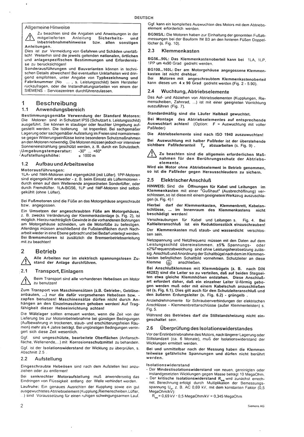
231
232
233

234
235
236
237
238
239
240
241
242
243
244
245
246
247
248
249
250
251
252
253

254 A PCC Flow Technologies, Inc. Company Environment One Corporation 2773 Balltown Road Niskayuna, New York USA Tel: (01) FAX:
Generator Gas Analyzer (GGA)
") UTILITY SYSTEMS Generator Gas Analyzer (GGA) Instruction Manual HA0112P01 Rev. B Contents Specifications... 4 Application... 5 System Description... 6 System Electronics... 6 Display Panel... 6 Sensor
UTILITY SYSTEMS Generator Gas Analyzer (GGA) Instruction Manual HA0112P01 Rev. B Contents Specifications... 4 Application... 5 System Description... 6 System Electronics... 6 Display Panel... 6 Sensor
Generator Condition Monitor (GCM-X)
") UTILITY SYSTEMS Generator Condition Monitor (GCM-X) Installation and Operation Manual GA0353P01 Rev. G Contents Specifications... 6 Application... 7 Principle of Operation... 7 System Description... 9
UTILITY SYSTEMS Generator Condition Monitor (GCM-X) Installation and Operation Manual GA0353P01 Rev. G Contents Specifications... 6 Application... 7 Principle of Operation... 7 System Description... 9
Generator Condition Monitor (GCM-X) ATEX
 ATEX") UTILITY SYSTEMS Generator Condition Monitor (GCM-X) ATEX Installation and Operation Manual GA0456P01 Rev. A Contents Generator Condition Monitor (GCM-X)... 5 Safety Consideration... 5 Specifications...
UTILITY SYSTEMS Generator Condition Monitor (GCM-X) ATEX Installation and Operation Manual GA0456P01 Rev. A Contents Generator Condition Monitor (GCM-X)... 5 Safety Consideration... 5 Specifications...
CIRRUS PRO. User Manual and Responsibilities ASPIRATING FIRE DETECTOR
 CIRRUS PRO ASPIRATING FIRE DETECTOR User Manual and Responsibilities Protec Fire Detection (Export) Ltd, Protec House, Churchill Way, Nelson, Lancashire. BB9 6RT. Telephone: +44 (0) 1282 717171 Fax: +44
GASGUARDIAN Channel Controller OPERATING & INSTALLATION MANUAL
 GASGUARDIAN 2 3 2-Channel Controller OPERATING & INSTALLATION MANUAL GasGuardian 2 3 Operating and Installation Manual Table of Contents General description.... 3 Installation. 3 Locating the GasGuardian-2..
GG-2 2-CHANNEL GAS DETECTION CONTROL PANEL. Installation and Operation Manual
 GG-2 2-CHANNEL GAS DETECTION CONTROL PANEL Installation and Operation Manual 2 GG-2 Warning Use this product only in the manner described in this manual. If the equipment is used in a manner not specified
Beacon 800 Gas Monitor Operator s Manual
 Beacon 800 Gas Monitor Operator s Manual Part Number: 71-0037RK Revision: F Released: 4/18/17 www.rkiinstruments.com Product Warranty RKI Instruments, Inc. warrants gas alarm equipment sold by us to be
Pioneer-R16 Gas Monitor Operator s Manual
 Pioneer-R16 Gas Monitor Operator s Manual Edition 7/2/97 RKI INSTRUMENTS, INC RKI Instruments, Inc. 33248 Central Ave, Union City, CA 94587 (510) 441-5656 Chapter 1: Description About the Pioneer-R16 Gas
Model Gas Alarm Panel APPLICABILITY & EFFECTIVITY. This manual provides instructions for the following Sierra Monitor products:
 Model 2102 Gas Alarm Panel APPLICABILITY & EFFECTIVITY This manual provides instructions for the following Sierra Monitor products: Model Description 2102-00 Alarm Panel 2 Channel 2102-01 Alarm Panel 2
Model 4001 Series Single Channel Controller
 Model 4001 Series Single Channel Controller Sierra Monitor Corporation 1991 Tarob Court, Milpitas, CA 95035 (408) 262-6611 (800) 727-4377 (408) 262-9042 - Fax E-Mail: sales@sierramonitor.com Web site:
Mark 25 Ultrapure Water Conductivity Analyzer
 Martek Instruments, Inc. Mark 25 Ultrapure Water Conductivity Analyzer Instruction Manual WARRANTY POLICY Unless otherwise stated, MARTEK INSTRUMENTS, INC. warrants this equipment to be free from defects
SEC 2000 Millenium Infrared Gas Detector
 SEC 2000 Millenium Infrared Gas Detector Instruction and Operation Manual Sensor Electronics Corporation 5500 Lincoln Drive Minneapolis, Minnesota 55436 USA (952) 938-9486 Fax (952) 938-9617 Email: sales@sensorelectronic.com
GAS MONITOR Model Model
 Sierra Monitor Corporation 1991 Tarob Court, Milpitas, CA 95035 (408) 262-6611 (800) 727-4377 (408) 262-9042 - Fax E-mail: sierra@sierramonitor.com Web Site: www.sierramonitor.com GAS MONITOR Model 2350-00
Models LBW-420-LEL (24 VDC powered) Ammonia Leak Detector
 Ammonia Leak Detector") Models LBW-420-LEL (24 VDC powered) Ammonia Leak Detector CAUTION & SYMBOL DEFINITIONS: CAUTION: Gives detailed description of different situations to avoid or not avoid for the proper operation of the
Models LBW-420-LEL (24 VDC powered) Ammonia Leak Detector CAUTION & SYMBOL DEFINITIONS: CAUTION: Gives detailed description of different situations to avoid or not avoid for the proper operation of the
Beacon 200 Gas Monitor Operator s Manual. Part Number: RK Released: 6/6/08
 Beacon 200 Gas Monitor Operator s Manual Part Number: 71-2102RK Released: 6/6/08 Table of Contents Chapter 1: Introduction.................................................3 Overview.............................................................3
Spectron LSN (Life Safety Network) Suggested Specifications
 Suggested Specifications") 1. General 1.1 Scope A Dual-Lite Spectron LSN (Life Safety Network) Series Inverter System shall be furnished to provide a reliable source of power, and shall operate during a utility line deficiency without
1. General 1.1 Scope A Dual-Lite Spectron LSN (Life Safety Network) Series Inverter System shall be furnished to provide a reliable source of power, and shall operate during a utility line deficiency without
Controllers. Instruction Manual WARNING
 Controllers Instruction Manual WARNING THIS MANUAL MUST BE CAREFULLY READ BY ALL INDIVIDUALS WHO HAVE OR WILL HAVE THE RESPONSIBILITY FOR INSTALLING, USING OR SERVICING THIS PRODUCT. Like any piece of
Instruction Manual WARNING
 Controllers Instruction Manual WARNING THIS MANAUL MUST BE CAREFULLY READ BY ALL INDIVIDUALS WHO HAVE OR WILL HAVE THE RESPONSIBILITY FOR INSTALLING, USING OR SERVICING THIS PRODUCT. Like any piece of
Carbon Monoxide Transmitter
 Introduction The CO Transmitter uses an electrochemical sensor to monitor the carbon monoxide level and outputs a field-selectable 4-20 ma or voltage signal. The voltage signal may also be set to 0-5 or
MICROCAPSTAR End-Tidal CO 2 Analyzer Instruction Manual
 MICROCAPSTAR End-Tidal CO 2 Analyzer Instruction Manual Read instructions carefully before operating this device. ❶ This device is not to be used for Human Life Support applications. ❷ To avoid possible
1040 Gas Monitor INSTALLATION AND OPERATING INSTRUCTIONS AMC-1040 WITH INTEGRAL ELECTROCHEMICAL SENSOR
 1040 Gas Monitor INSTALLATION AND OPERATING INSTRUCTIONS AMC-1040 WITH INTEGRAL ELECTROCHEMICAL SENSOR IMPORTANT: Please read these installation and operating instructions completely and carefully before
CommStat 6. Controller for Redundant HVAC Systems PRODUCT DATA SHEET
 CommStat 6 Controller for Redundant HVAC Systems PRODUCT DATA SHEET General Description The CommStat 6 HVAC controller is designed for controlling up to six redundant air conditioners in an E-House or
GasScanner 8C. Eight Channel Monitor. Operator s Manual. MINT-0281-XX Rev. A 01/29/08
 GasScanner 8C Eight Channel Monitor Operator s Manual MINT-0281-XX Rev. A 01/29/08 Product Warranty Matheson Tri-Gas, Inc., warrants gas alarm equipment sold by us to be free from defects in materials,
Product Manual SZ1145
 Product Manual SZ114 General Purpose Monitor Communicating Controls Description The SZ114 is a microprocessor-based monitoring and alarm interface designed to monitor up to four 1000 Ω platinum temperature
Software Version 2.01 LEVEL MONITOR MODEL 220
 Software Version 2.01 LEVEL MONITOR MODEL 220 19 April 2000 CONTENTS 1. Introduction 1 1.1 Model Number Designation 2 1.2 Intrinsic Safety Considerations 3 2. Specification 4 3. Operation 6 3.1 Display
SAFETY CERTIFIED MODEL FP-700 COMBUSTIBLE GAS DETECTOR
 SAFETY MANUAL SIL 2 Certified Model FP-700 Combustible Hydrocarbon Gas Sensor Version 2.0 1 SAFETY CERTIFIED MODEL FP-700 COMBUSTIBLE GAS DETECTOR This manual addresses the specific requirements and recommendations
Powerohm Resistors Digital HRG System
 Installation and Operating Instructions Powerohm Resistors Digital HRG System This manual provides general information, installation, operation, maintenance, and system setup information for the Powerohm
CommStat 4 Controller
 CommStat 4 Controller CommStat 4 Telecom HVAC Controller The CommStat 4 is an HVAC controller designed specifically for controlling two redundant air conditioners, heat pumps and air conditioners with
Analog Room Pressure Monitor RPC Series
 Description The Room Pressure Monitor is used to measure differential pressure in the range of 0.125 to 1"wc or 30 to 250 Pa. It combines precision high sensitivity silicon sensing capabilities and the
DETECTION SYSTEMS. GCM Auto Alarm. Instruction Manual. GA0203P01 Rev. D
 DETECTION SYSTEMS GCM Auto Alarm Instruction Manual GA0203P01 Rev. D Contents Limited Warranty... 3 Warning... 4 Safety Consideration... 4 General Description... 5 Installation... 6 Initial Adjustments...
Beacon 110 Gas Monitor Operator s Manual
 Beacon 110 Gas Monitor Operator s Manual Part Number: 71-0110RK Revision: H Released: 12/5/17 RKI Instruments, Inc. www.rkiinstruments.com Product Warranty RKI Instruments, Inc., warrants gas alarm equipment
Product Manual SZ1144
 Product Manual SZ1144 Refrigeration Temperature Monitor Communicating Controls Description The SZ1144 is a microprocessor-based monitoring and alarm interface designed to monitor up to four 1000 Ω platinum
Two-Channel Gas Controller
 Two-Channel Gas Controller Specifications subject to change without notice. USA 09 Page of DESCRIPTION Highly configurable, UL 0 performance-tested and -certified, and wall-mounted gas monitor; continuously
Instruction Manual PCS-400-XY. Pump Controller. Y=2: 4-20 ma Y=6: 0-10 VDC X=5: 1-5 VDC. 4 Pump Control Relays 1 Alarm Relay 1 Signal Fail
 Manufacturers of Process Controls and Instrumentation Instruction Manual Model: Function: Input: PCS-400-XY Pump Controller X=2: 4-20 ma X=5: 1-5 VDC X=6: 0-10 VDC X=7: Output: Power: 4 Pump Control Relays
CommStat 4. Controller for Redundant Telecom HVAC Systems PRODUCT DATA SHEET. Features and Benefits
 CommStat 4 PRODUCT DATA SHEET Controller for Redundant Telecom HVAC Systems General Description The CommStat 4 is an HVAC controller designed specifically for controlling two redundant air conditioners,
INSTALLATION, OPERATING & MAINTENANCE INSTRUCTIONS FOR 870 SERIES INDUSTRIAL CONTROL PANELS
 INSTALLATION, OPERATING & MAINTENANCE INSTRUCTIONS FOR 870 SERIES INDUSTRIAL CONTROL PANELS GENERAL INDEECO Industrial Control Panels are designed to provide years of trouble free operation if properly
GasScanner 1C. Single Channel Monitor. Operator s Manual. MINT-0278-XX Rev A
 GasScanner 1C Single Channel Monitor Operator s Manual MINT-0278-XX Rev A Product Warranty Matheson Tri-Gas, Inc., warrants gas alarm equipment sold by us to be free from defects in materials, workmanship,
Single Point Freeze Protection Heat Trace Control TRACON MODEL FPT 130 Installation and Operation Manual
 We manage heat MANUAL Single Point Freeze Protection Heat Trace Control TRACON MODEL FPT 130 Installation and Operation Manual 1850 N Sheridan Street South Bend, Indiana 46628 (574) 233-1202 or (800) 234-4239
Unfired Steam Generators (Series RB) Installation, Operation and Maintenance
 Installation, Operation and Maintenance") Unfired Steam Generators (Series RB) Installation, Operation and Maintenance Horizontal USG Vertical USG 534-EN Please read and save these instructions Disclaimers This Installation, Operation, and Maintenance
Unfired Steam Generators (Series RB) Installation, Operation and Maintenance Horizontal USG Vertical USG 534-EN Please read and save these instructions Disclaimers This Installation, Operation, and Maintenance
Installation, Operation and Maintenance
 Bulletin No. 534 Installation, Operation and Maintenance Unfired Steam Generators (Series RB) Horizontal USG Vertical USG Disclaimers This Installation, Operation, and Maintenance Manual is intended to
DESIGN MANUAL. The information in this doucment is applicable to sensors built in September, 2009 or later (Firmware 3.0)
") DESIGN MANUAL MODEL GIR910 INFRARED CARBON DIOXIDE (CO 2 ) GAS SENSOR 70091 The information in this doucment is applicable to sensors built in September, 2009 or later (Firmware 3.0) The information and
DESIGN MANUAL MODEL GIR910 INFRARED CARBON DIOXIDE (CO 2 ) GAS SENSOR 70091 The information in this doucment is applicable to sensors built in September, 2009 or later (Firmware 3.0) The information and
Installation and Operations Manual
 Installation and Operations Manual H-IM-LLC February 2018 Part No. 25092501 Replaces H-IM-LLC (01/2014) Lead Lag Control System Table of Contents General Safety Information 2 Inspection 2 Warranty Statement
Remote Relay Module (RRM)
") Remote Relay Module (RRM) Instruction Manual WARNING THIS MANUAL MUST BE CAREFULLY READ BY ALL INDIVIDUALS WHO HAVE OR WILL HAVE THE RESPONSIBILITY FOR INSTALLING, USING OR SERVICING THIS PRODUCT. Like
Remote Relay Module (RRM) Instruction Manual WARNING THIS MANUAL MUST BE CAREFULLY READ BY ALL INDIVIDUALS WHO HAVE OR WILL HAVE THE RESPONSIBILITY FOR INSTALLING, USING OR SERVICING THIS PRODUCT. Like
GLD-30 Gas Leak Detector
 GLD-30 Gas Leak Detector Installation, Operation & Maintenance General: The Archer Instruments GLD-30 is an ambient air monitor, used to detect the presence of a target gas (or gases) and to alert operators
HTD. High Temperature Non-Cycling Refrigerated Compressed Air Dryers. Operation & Maintenance Manual. MODELS HTD 21 thru HTD 100
 HTD High Temperature Non-Cycling Refrigerated Compressed Air Dryers Operation & Maintenance Manual MODELS HTD 21 thru HTD 100 - TABLE OF CONTENTS - 1.0 GENERAL 2 1.1 How to use this manual 1.2 Symbols
M770 ph Controller Owner s Manual
 M770 ph Controller Owner s Manual Table of Contents I. Introduction page 2 A. Water Chemistry page 2 B. Safety page 3 C. System Components page 4 D. Specifications page 7 E. Controller Panel Descriptions
VA301C CONTROLLER WITH BACnet OPTION
 ORDERING INFORMATION VA301C Controller VA301C-DLC VA301C-DLC-BIP Gas detection controller with data logging, display and plastic housing. Gas detection controller with data logging and display, BACnet/IP
INSTALLATION, OPERATING & MAINTENANCE INSTRUCTIONS FOR 350 SERIES CIRCULATION HEATERS
 INDEECO Circulation Heaters are designed to provide years of trouble free operation if properly installed and maintained. Please read and follow these instructions for installing and maintaining the heater.
RK CO 2 Transmitter Operator s Manual
 65-2397RK CO 2 Transmitter Operator s Manual Part Number: 71-0185RK Revision: B Released: 7/18/14 RKI Instruments, Inc. www.rkiinstruments.com WARNING Read and understand this instruction manual before
WATCHMAN Model LBW-WATCHMAN Ammonia Leak Detector
 WATCHMAN Model LBW-WATCHMAN Ammonia Leak Detector IMPORTANT READ THIS FIRST....3 CAUTIONS... 3 AVOIDING NUISANCE ALARMS... 3 STANDARD FEATURES... 4 AVAILABLE OPTIONS... 4 PARTS DESCRIPTION... 5 FRONT PANEL
Rev Pulse Modulating and Anti- Sweat Control (PMAC II Solo) Installation and Operation Manual
 Installation and Operation Manual") 026-1503 Rev 0 3-20-03 Pulse Modulating and Anti- Sweat Control (PMAC II Solo) Installation and Operation Manual 1640 Airport Road, Suite 104 Kennesaw, GA 31044 Phone: (770) 425-2724 Fax: (770) 425-9319
026-1503 Rev 0 3-20-03 Pulse Modulating and Anti- Sweat Control (PMAC II Solo) Installation and Operation Manual 1640 Airport Road, Suite 104 Kennesaw, GA 31044 Phone: (770) 425-2724 Fax: (770) 425-9319
Soft Start Series MP700 Solid State, Reduced Voltage
 Metron Fire Pump Controls and Accessories Soft Start Series MP700 Solid State, Reduced Voltage Metron Fire Pump Controllers conform to the latest requirements of National Fire Protection Association s
MODEL FPT-130 SINGLE POINT FREEZE PROTECTION HEAT TRACE CONTROL
 TRACON MODEL FPT-130 SINGLE POINT FREEZE PROTECTION HEAT TRACE CONTROL TABLE OF CONTENTS FPT 130 Overview... 2 Installation... 3 Power Source and Load Connections... 4 Temperature Sensor... 5 External
Hazardous Area Zirconia Oxygen Systems
 Operating Instructions IM/EXGP-INT_7 Hazardous Area Zirconia Oxygen Systems Interface Electronics Unit ABB The Company We are an established world force in the design and manufacture of instrumentation
1022 R/T Remote Monitor
 1022 R/T Remote Monitor INSTRUCTIONS AMC-1022R/T WITH REMOTE SENSOR OR TRANSMITTER INSTALLATION AND OPERATING INSTRUCTIONS FOR THE AMC-1022R/T UNIT IMPORTANT: Please read these installation and operating
PL400 Patient Lift Scale Indicator Owner s Manual
 PL400 Patient Lift Scale Indicator Owner s Manual CARDINAL SCALE MFG. CO. 8551-M912-01 Rev C PO BOX 151 WEBB CITY, MO 64870 Printed in USA 07/04 PH (417) 673-4631 - FAX (417) 673-5001 www.cardinalscale.com
Across-the-Line SERIES MP300 Combined Manual and Automatic
 Across-the-Line SERIES MP300 Combined Manual and Automatic Metron Fire Pump Controllers conform to the latest requirements of National Fire Protection Association s Standard for Centrifugal Fire Pumps
Sentry LIQUID LEVEL GAUGE MODEL 200 or 200C OWNER MANUAL REV 1.7 SEPT08 PAGE 1 OF 12
 PAGE 1 OF 12 TABLE OF CONTENTS PAGE 1. SAFETY PRECAUTIONS 1.1. Electrical shock 3 2. APPLICATION 3 3. INSTALLATION 3.1. Mount indoor alarm display 3.2. Mount the outdoor junction box 3.3. Install interconnecting
DESCRIPTIVE AND INSTALLATION INSTRUCTION MANUAL FOR MODEL G1000 AND H1000 SERIES ANNUNCIATORS
 DESCRIPTIVE AND INSTALLATION INSTRUCTION MANUAL FOR MODEL G1000 AND H1000 SERIES ANNUNCIATORS SEEKIRK, INC. 2420 Scioto Harper Dr. Columbus, OH 43204 Tel: (614) 278-9200 FAX: (614) 278-9257 email: seekirk@seekirk.com
Flopurge TS. Operation Manual
 Flopurge TS Operation Manual Part Number 079-0204 Spectron Gas Control Systems United Kingdom Unit 4, Herald Court, University of Warwick Science Park, Coventry, CV4 7EZ +44 (0)24 7641 6234 sales@spectron-gcs.com
SPECIFICATION CHEMGARD INFRARED GAS MONITOR SERIES
 SPECIFICATION CHEMGARD INFRARED GAS MONITOR SERIES USER INSTRUCTIONS FOR THE CHEMGARD INFRARED GAS MONITOR SERIES To completely customize the specification to your exact application, modification to the
CA5000 Liquid CO 2 Freezer Backup System
 CA5000 Liquid CO 2 Freezer Backup System OPERATING INSTRUCTIONS MANUAL HAMPSHIRE CONTROLS CORPORATION ONE GROVE STREET / P.O. BOX 516, DOVER, NEW HAMPSHIRE USA 03821 TEL. (603) 749-9424 FAX (603) 749-9433
FIRE ALARM CONTROL EQUIPMENT. Addendum October 2006 Instructions for new style EN54-4 Power supply unit module
 FIRE ALARM CONTROL EQUIPMENT Addendum October 2006 Instructions for new style EN54-4 Power supply unit module MXLK-05 Issue 2.0 June 2007 INSTALLATION Safety Suppliers of articles for use at work are required
AMC-RAM-4. Refrigerant Alarm Module USER MANUAL. Please read the installation and operating instructions completely and carefully before starting.
 AMC-RAM-4 Refrigerant Alarm Module USER MANUAL IMPORTANT: Please read the installation and operating instructions completely and carefully before starting. Filename: 3310405B, DOC, AMC_RAM4_Manual.doc
Operating & Maintenance Manual. Alert-4 Ethernet LCD Master Alarm
 Operating & Maintenance Manual Alert-4 Ethernet LCD Master Alarm w w w. a m i c o. c o m Contents User Responsibility 4 Introduction 4 Features 5 Description of the Alarm 5 Shipment Details 5 The Alarm
AS950 REFRIGERATED SAMPLERS
 AS950 REFRIGERATED SAMPLERS Applications Wastewater Collections Industrial Pretreatment Environmental Monitoring Stormwater Sampling has never been this easy. The AS950 Refrigerated Sampler makes programming,
GG-NH3-2% AMMONIA GAS SENSOR. Installation and Operation Manual
 GG-NH3-2% AMMONIA GAS SENSOR Installation and Operation Manual 2 GG-NH3-2% Warning Use this product only in the manner described in this manual. If the equipment is used in a manner not specified by Calibration
DESCRIPTIVE AND INSTALLATION INSTRUCTION MANUAL FOR MODEL AH1000, BH1000, AND EH1000 SERIES ANNUNCIATORS
 DESCRIPTIVE AND INSTALLATION INSTRUCTION MANUAL FOR MODEL AH1000, BH1000, AND EH1000 SERIES ANNUNCIATORS SEEKIRK, INC. 2420 Scioto Harper Dr. Columbus, OH 43204 Tel: (614) 278-9200 FAX: (614) 278-9257
Flostop TS D7E and A8E. Operation Manual
 Flostop TS D7E and A8E Operation Manual United Kingdom Spectron Gas Control Systems Ltd, Unit 4, ATU1, University of Warwick science Park, Coventry, +44 (0) 24 7641 6234 sales@spectron-gcs.com Germany
Pre-March 2016 Design - Click to be redirected to newer SBS-H2 design SBS-H2. Hydrogen Gas Detector Kit
 Pre-March 2016 Design - Click to be redirected to newer SBS-H2 design N56 W16665 Ridgewood Drive Menomonee Falls, WI 53051 SBS-H2 Hydrogen Gas Detector Kit For battery charging rooms and other areas where
FLCH4R Garage and Utility Electric Heater
 FLCH4R Garage and Utility Electric Heater Installation, Operation & Maintenance Instructions Model No. Volts Amps Watts BTU/HR Phase High Low High Low High Low Min Fuse Size* FLCH4R 208 17.3 8.66 3600
MODEL GPT-130 SINGLE POINT HEAT TRACE CONTROL THERMOSTAT
 TRACON MODEL GPT-130 SINGLE POINT HEAT TRACE CONTROL THERMOSTAT TABLE OF CONTENTS GPT 130 Overview... 2 Installation... 3 Power Source and Load Connection... 4 Temperature Sensor Installation... 5 Panel
Pipe Freeze Protection Control SCFP-CO-F130 Installation and Operation Manual
 MANUAL Pipe Freeze Protection Control SCFP-CO-F130 Installation and Operation Manual Model FPT 130 Single Point Freeze Protection Heat Trace Control Table of Contents SCFP-CO-F130 Overview... 3 Installation...
WARNING Important Safety Information
 1 Specifications Premier Series Non-Programmable Thermostats MODEL 3000 MODEL 3200 1 2 3 4 Specifications Installation Testing Your New Thermostat Programming User Settings WARNING Important Safety Information
RK-05 Combustible Gas Transmitter Operator s Manual
 65-2405RK-05 Combustible Gas Transmitter Operator s Manual Part Number: 71-0180RK Revision: 0 Released: 2/16/11 RKI Instruments, Inc. www.rkiinstruments.com WARNING Read and understand this instruction
CO Guardian LLC Document: E. AIRPORT DRIVE Date: 11/15/05 OWNERS MANUAL
 OWNERS MANUAL CARBON MONOXIDE DETECTOR MODELS Panel mount and Remote Detectors (R) (353 and 353R) 353 FAMILY MODEL OWNERS/INSTALLATION MANUAL Page 1 of 22 LOG OF REVISIONS REV NO. PAGE NO. DATE DESCRIPTION
Warranty Registration
 WARRANT Y AND LIMITS OF LIABILIT Y Vulcain Inc. warrants to the original purchaser that its product, and the component parts thereof, will be free from defects in workmanship and materials for a period
SBS-H2. Hydrogen Gas Detector Kit. For battery charging rooms and other areas where hydrogen gas may be present
 SBS-H2 Hydrogen Gas Detector Kit For battery charging rooms and other areas where hydrogen gas may be present INSTALLATION, OPERATING & MAINTENANCE INSTRUCTIONS Protects Life, Property, and Profits Compliant
RK-03 Hydrogen Detector Operator s Manual
 61-1001RK-03 Hydrogen Detector Operator s Manual Part Number: 71-0371 Revision: P1 Released: 5/26/15 www.rkiinstruments.com WARNING Read and understand this instruction manual before operating detector.
MODEL DPS1 Heated Dew Point Measuring System OPERATORS MANUAL
 MODEL DPS1 Heated Dew Point Measuring System OPERATORS MANUAL 19 Brigham Street Unit #8 Marlborough, MA USA 01752 Tel: (508) 263-5900 (800) 276-3729 Fax: (508) 486-9348 E-mail: h2o@edgetech.com www.edgetech.com
RK-05 Carbon Monoxide Detector Operator s Manual
 65-2433RK-05 Carbon Monoxide Detector Operator s Manual Part Number: 71-0189RK Revision: 0 Released: 5/17/11 RKI Instruments, Inc. www.rkiinstruments.com WARNING Read and understand this instruction manual
Installation, Operation & Service Manual
 Installation, Operation & Service Manual WARNING Improper installation, adjustment, alteration, service or maintenance can result in death, injury or property damage. Read the Installation, Operation and
GASGUARD H 2-1% Hydrogen Sensor OPERATING & INSTALLATION MANUAL
 GASGUARD H 2-1% Hydrogen Sensor OPERATING & INSTALLATION MANUAL 2 Table of Contents GasGuard H 2-1% General description. 4 Installation.. 4 Locating the sensor. 4 Installation guidelines 5 Wiring.. 6 Operation..
SPECIFICATION: AlarmLine TM INTELLIGENT LINEAR HEAT DETECTION
 1. GENERAL SPECIFICATION 1.1 The contractor shall provide an Intelligent AlarmLine Linear Heat Detection System to perform the following functionality: A. Fire Alarm, Supervisory and Trouble-Event Initiation
RK-02 Multi Point Detector Operator s Manual
 65-2485RK-02 Multi Point Detector Operator s Manual Part Number: 71-0237RK Revision: A Released: 11/26/14 RKI Instruments, Inc. www.rkiinstruments.com WARNING Read and understand this instruction manual
Variable Frequency Drive SERIES MP800 VFD
 Metron Fire Pump Controls and Accessories Variable Frequency Drive SERIES MP800 VFD Metron Fire Pump Controllers conform to the latest requirements of National Fire Protection Association s Standard for
Power Supply Display Module PSDM. Installation and Operation Manual
 Power Supply Display Module PSDM Installation and Operation Manual Read this manual before using this product. Failure to follow the instructions and safety precautions in this manual can result in serious
Nitrogen Dioxide (NO2) Single-Point Gas Detection System
 Single-Point Gas Detection System") Nitrogen Dioxide (NO) Single-Point Gas Detection System DESCRIPTION Wall-mounted gas monitor with built-in nitrogen dioxide (NO)/diesel fume gas sensor, accepts one analog remote device such as a secondary
Nitrogen Dioxide (NO) Single-Point Gas Detection System DESCRIPTION Wall-mounted gas monitor with built-in nitrogen dioxide (NO)/diesel fume gas sensor, accepts one analog remote device such as a secondary
WATLOW IND. WATROD Modular Duct Heater Installation & Maintenance Manual I&M NUMBER: Page: 1 Date:6/11/2008 Rev: 2
 I&M NUMBER: 316-42-15-1 Page: 1 _ Pre Installation Check to make sure that heater received is the same as that ordered. Elements may come in contact with each other during shipment. Minor adjustments to
MASTER PRESSRE MAINTANENCE CONTROLLER. Models PMCE INSTRUCTION MANUAL. C 2018 Master Control Systems, Inc
 MASTER PRESSRE MAINTANENCE CONTROLLER Models PMCE INSTRUCTION MANUAL C 2018 Master Control Systems, Inc TABLE OF CONTENTS Important Safety Information. Page 3 General Description and Installation.. Page
Document No
 CO Guardian LLC 1951 E. Airport Dr. Tucson, AZ 85706 CARBON MONOXIDE DETECTOR MODEL 452 INSTALLATION AND OPERATIONAL MANUAL Document No. 01-2510-02 MODEL 452 INSTALLATION AND OPERATIONAL MANUAL Page 1
OVEN INDUSTRIES, INC.
 OVEN INDUSTRIES, INC. OPERATING MANUAL Model 5C7-252 TEMPERATURE CONTROLLER With PLC Inputs Introduction Thank you for purchasing our controller. The Model 5C7-252 is an exceptionally versatile unit and
RK Carbon Monoxide Transmitter Operator s Manual
 65-2335RK Carbon Monoxide Transmitter Operator s Manual Part Number: 71-0177RK Revision: 0 Released: 4/12/11 RKI Instruments, Inc. www.rkiinstruments.com WARNING Read and understand this instruction manual
Dual Point General Purpose Heat Trace Control TRACON MODEL GPT 230 Installation and Operation Manual
 We manage heat MANUAL Dual Point General Purpose Heat Trace Control TRACON MODEL GPT 230 Installation and Operation Manual 1850 N Sheridan Street South Bend, Indiana 46628 (574) 233-1202 or (800) 234-4239
ESP TECHNOLOGIES LIMITED
 Alarm Technology ESPAN-01 Series Annunciator System Combination type User Manual (Rev. 1) ESP TECHNOLOGIES LIMITED www.esptechno.com Content Page Introduction 2 General Description 2 Overview - Annunciator
Instruction Manual Model Backup Switch, 1 for 8
 Instruction Manual Model 2582-282 Backup Switch, 1 for 8 December 2011, Rev. 0 MODEL 2582 SWITCH CROSS TECHNOLOGIES INC. SWITCH ALARM PSA PSB ALARM OFFLINE ONLINE UNIT STATUS 1 2 3 4 5 6 7 8 BU PROT MODE
MASTER JOCKEY PUMP CONTROLLER. Model JPCE INSTRUCTION MANUAL. C 2018 Master Control Systems, Inc
 MASTER JOCKEY PUMP CONTROLLER Model JPCE INSTRUCTION MANUAL C 2018 Master Control Systems, Inc TABLE OF CONTENTS Important Safety Information. Page 3 General Description and Installation.. Page 4 Model
RELEASE DEVICES RELEASE DEVICE-WPS MODELS A/B INSTALLATION MANUAL U.L. LISTED CANADIAN LISTED CSFM: :100 GENERAL DESCRIPTION:
 RELEASE DEVICES MADE IN THE U.S.A. RELEASE DEVICE-WPS MODELS A/B INSTALLATION MANUAL U.L. LISTED CANADIAN LISTED CSFM: 7300-1418:100 GENERAL DESCRIPTION: S/N: The "WPS" World Power Series, Time Delay Release
WARNING Important Safety Information
 1 Specifications Premier Series Non-Programmable Thermostats MODEL 3000 MODEL 3200 1 2 3 4 5 Specifications Installation Testing Your New Thermostat Programming User Settings Temperature Adjustment WARNING
Dual Point General Purpose Heat Trace Control TRACON MODEL GPT 230 Installation and Operation Manual
 We manage heat MANUAL Dual Point General Purpose Heat Trace Control TRACON MODEL GPT 230 Installation and Operation Manual 1850 N Sheridan Street South Bend, Indiana 46628 (574) 233-1202 or (800) 234-4239