DECK 1 DECK 2 DECK 3 DECK 4 DECK 5. In the event of an enquiry please quote these serial numbers.
|
|
|
- Jerome Mills
- 5 years ago
- Views:
Transcription
 DECK 4 DECK 5 In the event of an enquiry please quote")

1 MANUAL No. Y-DXT UL Enter Serial Nos. here DECK 1 DECK 2 DECK 3 FAN (IF FITTED) DECK 4 DECK 5 In the event of an enquiry please quote these serial numbers. Store this document safely and ensure it is available at all times. Non-availability may affect the service / repair of your machine. OPERATION AND MAINTENANCE MANUAL MODULAR DECK OVEN FG257 MODULAR DECK UL 08/07 RAC ECOTOUCH CONTROL 18/06/2013 1
. NO USER SERVICEABLE PARTS INSIDE. REPAIR SHOULD BE DONE BY AUTHORISED PERSONNEL ONLY.")

2 WARNING LABEL, TO REDUCE RISK OF FIRE OR ELECTRIC SHOCK DO NOT REMOVE COVER (OR BACK) NO USER SERVICEABLE PARTS INSIDE REPAIR SHOULD BE DONE BY AUTHORISED PERSONNEL ONLY IMPORTANT NOTES TO REDUCE RISK OF FIRE OR ELECTRIC SHOCK, DO NOT REMOVE COVERS (OR BACK SHEETING). NO USER SERVICEABLE PARTS INSIDE. REPAIR SHOULD BE DONE BY AUTHORISED PERSONNEL ONLY. FAILURE TO ADHERE TO THE CLEANING AND MAINTENANCE INSTRUCTIONS DETAILED IN THIS MANUAL COULD AFFECT THE WARRANTY OF THIS MACHINE. THE OVEN SHOULD ONLY BE USED FOR BAKING BREAD, PASTRIES AND CAKES SOME SECTIONS OF THIS MANUAL ARE FOR ENGINEERS ONLY AND THE CUSTOMER SHOULD NOT ATTEMPT TO MAKE ALTERATIONS. BEWARE OF HOT SURFACES. DO NOT TOUCH OVEN FRONT OR DOOR WITH BARE SKIN. 2
3 CONTENTS Section Section Section Section Section Section Section Section Introduction Overall Dimensions Specifications Safety Installation Isolation Cleaning Operating Conditions Section Principles Of Operation (and baking advice) Section Section Section Operating Ins tructions Troubleshoot ing Service Infor mation Replacing light bulbs Section Spares Information THIS SECTION IS FOR ENGINEERS ONLY AND THE CUSTOMER SHOULD NOT ATTEMPT TO MAKE ALTERATIONS. Section Electrical Information Section WARNING and INFORMATION LABELS 3

4 1.0 INTRODUCTION The electric modular Deck Oven is an easy to use practical, good-looking oven, giving an excellent heat recovery rate and an even bake across a wide range of bread and confectionery products. Good looking and totally reliable Conceived with the no nonsense requirements of both the independent and in-store baker in mind, and designed to visually please as well as give reliable service for many years. This oven will more than satisfy the most discerning customer. Top quality specification The external and internal contact surfaces are stainless steel. Each modular deck is fitted with durable reinforced one-piece tiles, and an increase in high-grade insulation and high temperature ceramic sealant, makes the oven more efficient. The oven comes with a patented integral steaming system, which reduces energy consumption and the overall size of the oven. The system produces real steam with the advantages of spray steam. Pre-steam is also available to reduce the affects of long loading times. No drainage is required. Ecotouch ovens are supplied with TOUCH displays for the user-friendly control panels. This can show pictures of product types or program numbers that have been set by the user. When not being used, the screen can show your company logo. A voice prompt facility is also available for the basic instructions like Bake over. ECOTOUCH SCREEN CONTROLS The lights are low voltage, sealed from the chamber and easily accessed from outside the oven. Fitted with a choice of hinged easy to clean double glazed doors (using low energyloss reflective glass for high visibility) or metal doors, means low energy consumption and the high kw rating gives good recovery. (0-100% heating available both top and bottom) As it is our policy to improve our machines continuously, we reserve the right to change specifications without prior notice. 4
 3 Tray wide oven. W = 74 ½ (1890mm) 2 Tray wide oven. W = 55 ¾ (1416mm) 1 Tray wide oven. W = 37 (940mm) FG257 MODULAR DECK UL 08/07 RAC 5")
5 2.0 OVERALL DIMENSIONS ALL DIMENSIONS ARE APPROXIMATE H D W 5 HIGH.H = 84 (2135mm) 4 HIGH.H = 79.5 (2020mm) 3 HIGH.H = 79.5 (2020mm) Ovens available with 1,2,3, 4, and 5 modules 32 deep modules... D = 51 ¾ (1300mm) 3 Tray wide oven. W = 74 ½ (1890mm) 2 Tray wide oven. W = 55 ¾ (1416mm) 1 Tray wide oven. W = 37 (940mm) FG257 MODULAR DECK UL 08/07 RAC 5
6 3.0 SPECIFICATIONS Dimensions in millimetres 25.4mm = 1 5 DECK OVEN DECK PLATE HEIGHTS 4 DECK OVEN DECK PLATE HEIGHTS 3 DECK OVEN DECK PLATE HEIGHTS 6
7 7
8 ELECTRICAL LOADINGS: SUPPLY REQUIRED PER MODULAR DECK: 3 TRAY WIDE 2 TRAY WIDE 1 TRAY WIDE 3 Phase (3 wire + ground), 220V. 60Hz 8.85kW, 24Amp 5.93kW,18Amp 3.0kW, 9A mp 3 Phase (3 wire + ground), 208V. 60Hz 7.90kW, 22Amp 5.31kW,17Amp 2.7kW, 8.7 Amp OVERLOAD PROTECTION 30AMPS 30AMPS 3 Phase (3 wire + ground), 480V. 60Hz 8.78kW, 12.4Amp 5.86kW,8.2Amp 4.9kW, 7A mp OVERLOAD PROTECTION 20AMPS 20AMPS SUPPLY REQUIRED FOR CANOPY: 1 Phase (2 wire + ground), 220V. 60Hz Fused at 6Amps 1 Phase (2 wire + ground), 208V. 60Hz Fused at 6Amps NOISE LEVEL: Less than 80 Db WEIGHT: (ALL WEIGHTS ARE APPROXIMATE) Total oven weight (Including base frame) 2 tray wide, 3 deck 3 tray wide, 3 deck 1 tray wide, 3 deck = TBA Weight per oven chamber module Weight per oven canopy module Weight per fan module Weight of product (max) per deck 2 tray wide 3 tray wide 1 tray wide 2 tray wide 3 tray wide 1 tray wide 2 tray wide 3 tray wide 1 tray wide 2 tray wide 3 tray wide 1 tray wide = 421lbs = 575lbs = TBA = 31lbs = 38lbs = TBA = 62lbs = 62lbs = TBA = 86lbs = 131lbs = TBA (191.5kg) (261kg) (14kg) (17kg) (28kg) (28kg) (39kg) (60kg) = = 1569lbs 2345lbs (711kg) (1064kg) 8
9 4.0 SAFETY All maintenance must be made with the oven disconnected from the power supply and then only by fully trained authorized persons. Check all cover panels, and any pipefittings are securely positioned. Check oven door handles are not damaged. Do not operate a deck's steaming system with oven door open. Always use oven gloves when loading the oven. When products are removed from the oven, ensure: (a) Tins are knocked out and stored directly onto tin storage trolley or rack (Do not leave hot tins on the floor or on tables). (b) Trays are put into a rack and the rack is wheeled to a safe cooling area. Do not store items on top of the oven. Do not store items behind the oven. Beware of hot surfaces. Do not touch oven front or door with bare skin. All operatives must be fully trained People undergoing training must be under direct supervision The oven should only be used for baking bread, pastries and cakes (for other products please contact your oven supplier) No unauthorized modifications should be made to the oven. Do not walk on the roof of the oven DISPOSAL Care should be taken when the oven comes to the end of its working life. All parts should be disposed of in the appropriate place, either recycling or other means as the law permits at the time. NOTE: BAKERY STAFF MUST NOT UNDER ANY CIRCUMSTANCES REMOVE PANELS TO ACCESS ANY PART OF THE DECK OVEN. Panels should only be removed by an Adamatic maintenance engineer (or other fully trained maintenance contractor) for repairs or maintenance, after isolating oven from power supply. The Bakery Manager or the Bakery Supervisor must carry out the above daily safety checks FG257 MODULAR DECK UL 08/07 RAC 9
10 5.0 INSTALLATION GENERAL A hard smooth level floor is recommended on which to position the oven and access for maintenance should be considered. The oven is not designed to be built in so sufficient clearance must be left in front of the access panels (right hand side) to allow for servicing. If not chosen as an oven option, it is recommended that an extraction hood be placed above the oven to disperse excess steam and heat, which could have an adverse effect on the bakery ceiling and ambient temperature. A wall isolator rated at 30Amps must be available in order to completely isolate the oven. THIS ISOLATOR MUST BE CLEARLY ACCESSIBLE TO THE OVEN OPERATOR A chain retainer should be fitted, that is shorter than the power cables, to protect them from strain if the oven is moved. (Fit to the wall or floor and the base, using hole provided in castor fixing corner plates). Installation must be made by a trained authorized engineer and all utilities must be installed by licensed contractors and must conform to all local and state building codes. The oven must be run in as stated in the initial start up instructions. ELECTRICAL CONNECTIONS Each modular deck requires its own power supply. SUPPLY REQUIRED PER MODULAR DECK: 3 TRAY WIDE 2 TRAY WIDE 1 TRAY WIDE 3 Phase (3 wire + ground), 220v. 60Hz 8.85kW, 24Amp 5.93kW,18Amp 3.0kW, 9Amp 3 Phase (3 wire + ground), 208v. 60Hz OVERLOAD PROTECTION 7.90kW, 22Amp 30AMPS 5.31kW,17Amp 30AMPS 2.7kW, 8.7Amp 3 Phase (3 wire + ground), 480v. 60Hz 8.78kW, 12.4Amp 5.86kW,8.2Amp 4.9kW, 7Amp OVERLOAD PROTECTION 20AMPS 20AMPS SUPPLY REQUIRED FOR CANOPY: 1 Phase (2 wire + ground), 220v. 60Hz Fused at 6Amps 1 Phase (2 wire + ground), 208v. 60Hz Fused at 6Amps FG257 MODULAR DECK UL 08/07 RAC 10

 1310mm 3 TRAY 836mm - -")
11 DECK OVEN BUILDING A B C D E F G H I J K BASE TO DECK MODULE SEALANT MODULE TO MODULE FIXING MODULES FLUE JOINTS EVAPORATING/DRIP TRAY SIDE PANELS and EARTHQUAKE BRACKETS IMPORTANT OPERATIONS WATER SYSTEM SETUP EXHAUST CONNECTIONS INITIAL START-UP LIFTING POINTS M10 THREADED LIFTING POINTS, 4 POSITIONS (ALSO USED AS LOCATORS TO POSITION EACH DECK) 1310mm 3 TRAY 836mm TRAY 858mm 11

12 JOINING DECK SECTIONS REST MODULE APPROX. 4 FROM FRONT OF BASE A FRONT BASE MODULE APPLY SILICON ALL THE WAY ACROSS FRONT JOIN AREA. LIFT MODULE AND LOWER ONTO POSITIONING PINS THIS WILL COMPRESS THE SEALANT. B SEALANT ACROSS FRONT. BOLT BASE AND MODULE TOGETHER AT 4 CORNERS SEAL AND POSITION EACH ADDITIONAL MODULE AS ABOVE. SEE INSTRUCTIONS FOLLOWING FOR FIXING. C FRONT. 12


 FRONT F FIT EVAPORATING DRIP")
13 ENSURE ALL FRONT FACES LINE UP THEN BOLT TOGETHER EACH MODULE. 1 FIXING EACH SIDE AT FRONT. D FRONT E WHEN ALL MODULES ARE POSITIONED AND FIXED AT THE FRONT, ATTACH JOINING BRACKETS TO FLUE JOINTS. (SELF-TAPPING SCREWS) FRONT F FIT EVAPORATING DRIP TRAY TO THE BOTTOM SECTION. (SELF-TAPPING SCREWS) 13
 AND THEN TIGHTEN SCREWS.")

 over frame and fix to floor in 2 positions NOTE If")
14 G FIT SIDE PANELS. FIX SCREWS BUT DO NOT TIGHTEN. MOVE PANELS TO LINE UP FRONT EDGES (HOLES ARE SLOTTED) AND THEN TIGHTEN SCREWS. FRONT SCREWS CLAMPING DOWN IN EARTHQUAKE ZONES The base structure should be held in place by bolting down to the floor with suitable fixings, using bracket part number in diagonally opposite corners. Holes for fixings Clamp bracket ( ) over frame and fix to floor in 2 positions NOTE If this method of fixing down is used, enough space should be left surrounding the oven to allow for maintenance and cleaning, without moving the oven. 14


15 H IMPORTANT OPERATIONS EARTH STRAP EARTH (GROUND) STRAPS MUST BE CONNECTED BETWEEN EACH SECTION. PART NUMBER M SUPPLIED REAR VIEW OF OVEN TILE RETAINING BRACKETS RETAINING BRACKETS IN 2 POSITIONS ON EACH DECK POSITION ON DELIVERY TURN BRACKET 180 DEGREES. POSITION AFTER INSTALLATION REMOVE SCREWS (2 PER BRACKET, NOT SHOWN). TURN BRACKET 180 DEGREES. ADJUST BRACKET TO TOUCH TILE AND REFIT SCREWS. THIS MUST BE DONE ON EACH DECK. BRACKET PART No.M
16 I WATER SUPPLY REQUIREMENTS The set up procedure on the next page must be followed to allow the steaming system to function correctly THIS EQUIPMENT IS TO BE INSTALLED TO COMPLY WITH THE APPLICABLE FEDERAL, STATE, OR LOCAL PLUMBING CODES All ovens with steam require a ½ NPT hot or cold water supply at a pressure of 2-3 bar (29 44 psi). Located approximately 10 from the right and 4 from the top of the stand when facing the front of the oven. Only one water supply is required per oven. A manifold supplies all decks from one connection point. For proper operation of the steam system it is recommended that the water supply follows the following specifications: Hardness 0-4 grains per gallon PH range 7.0 to 8.5 Chloride concentration Calcium Magnesium Alkalinity 0 30 ppm 0 4 ppm 0 4 ppm 0 20 ppm Consult your water treatment company for proper water filtration system information. No drain is required for this oven. A Dual Check Valve Backflow Prevention Device is supplied fitted to the water inlet manifold. FG257 MODULAR DECK UL 08/07 RAC 16

17 WATER SYSTEM SETUP PROCEDURE It is imperative that the water delivery to the deck oven is checked for the steam system to operate correctly 1. Flush out the main feed pipe to be used, until water runs clear and free from debris. 2. Connect main feed to oven. 3. Connect flexible hoses to each deck. 4. Place a container under the test valve. 5. Slowly open test valve fully and with the water flowing check the regulator is set to 0.75 bar. If not adjust using the screw above the valve. Never use the oven above this setting 6. When the pressure has stabilised shut the test valve. REPEAT 4,5 AND 6 AT THE END OF INSTALLATION. NOTE. DYNAMIC PRESSURE, NOT STATIC, IS BEING MEASURED. TO OVENS REGULATOR DUAL CHECK VALVE BACKFLOW PREVENTION DEVICE STOP TAP TEST VALVE ADJUSTING SCREW SET TO 0.75 bar FILTER WATER REGULATOR SET UP LOCATED ON REAR OF OVEN 17

18 J Exhaust Connections (IF CANOPY FITTED) Ideally an exhaust duct should rise 78 (2 metres) above the bakery roof protected from wind and birds by a duct protector. It should be of a suitable material to take the high temperatures and humidity expected. It should be flexible and easily removable at the oven connection point. This allows the oven to be moved for cleaning when required. 10 Dia.SPIGOT CONNECTION POINT 23 CANOPY 9 ½ ROOF WITH EXTRACTION FAN FITTED Dia.SPIGOT CONNECTION POINT WITHOUT EXTRACTION FAN FITTED 18
19 K INITIAL START UP THIS PROCEDURE MUST BE ADHERED TO FOR THE OVEN WARRANTY TO BE VALID. In order for the oven to give good reliable service the deck tiles must be initially brought up to temperature as stated below. After this running in period the oven can be used as required. Running in procedure 1. Turn the oven on and note the temperature shown. (This will be the temperature inside the cooking chamber) 2. The temperature needs to rise to 110deg C, at no more than 2deg a minute. DO NOT USE BOTTOM HEAT AT ANY TIME. 3. Take the temperature up to 260deg C, at no more than 1deg in 2 minutes. THIS WILL TAKE 5 HOURS. 19

20 6.0 ISOLATION WARNING THE POWER OFF BUTTON ON THE FRONT OF THE OVEN DOES NOT ISOLATE THE POWER SUPPLY. A WALL ISOLATOR RATED AT 30AMPS MUST BE AVAILABLE IN ORDER TO COMPLETELY ISOLATE THE OVEN. THIS ISOLATOR MUST BE CLEARLY ACCESSIBLE AND KNOWN TO THE OVEN OPERATOR TO STOP THE OVEN IN AN EMERGENCY SWITCH OFF AT THE MAIN WALL ISOLATOR FG257 MODULAR DECK UL 08/07 RAC 20
21 7.0 CLEANING DAILY CLEANING INSTRUCTIONS ISOLATE OVEN FROM MAINS SUPPLY BEFORE CLEANING. After the oven has been allowed to cool, (this could take several hours), sweep any debris out. Use a vacuum cleaner with metal attachments (able to take heat) if available. Brush down and wipe oven front, back and sides with a damp cloth. Spot clean with a damp cloth, which has been soaked in a solution of mild detergent, and hot water, paying particular attention to ensure excess water is not applied around the area of the electrical panels. NOTE: TAKE CARE WATER DOES NOT ENTER CONTROL PANEL MOUNTING OR ROOF MOUNTED FAN. WEEKLY CLEANING INSTRUCTIONS ISOLATE OVEN FROM MAINS SUPPLY BEFORE CLEANING. Complete daily cleaning as above. Scrub oven wheels with a mild detergent and hot water using nylon cleaning brush (excess water will rust metal). Ensure the oven roof area is clear of debris and dust build up. (DO NOT STAND ON THE OVEN ROOF) FG257 MODULAR DECK UL 08/07 RAC 21
22 8.0 OPERATING CONDITIONS It is recommended that a space of at least 6 feet be left in front of the oven for ease of operation and safety. Bakery utensils must not be used to operate the control panel buttons. 9.0 PRINCIPLE OF OPERATION NOTE: REFER TO YOUR OWN COMPANY S RECIPE MANUAL FOR OVEN TEMPERATURE SETTINGS. PLEASE ALSO REFER TO THE BAKING ADVICE ON THE NEXT PAGE Products are baked in an insulated heated chamber. The temperature is regulated by a thermocouple having a read-out on the front control panel. Baking heat is radiant with top and bottom heat being adjusted by means of separate controls. This enables heat to be balanced according to product requirement. STEAM is provided from an integral steam unit, and is introduced into the chamber on demand. This is automatically controlled by the programmed parameters. Once steamed the oven will not steam until the steam unit has recovered heat, typically 3-8 minutes depending on the amount of steam selected. All ovens are fitted with a steam damper that evacuates steam humidity into a vent at the side of the oven. 22
23 Baking Advice For the best results from deck Ovens Loading 1. Do not place the products too close together. If the loaves are close to each other after oven spring (expansion), the loaves sides will be soft and may collapse on cooling. 2. Place the product evenly within the oven. Product bunched together will be paler than those widely spaced. 3. Product should not be placed too close to the edge of the tile. As it expands towards the front one side of the loaf may enter the cooler air by the door. 4. Door opening should be kept to a minimum because cold air enters the oven cooling the sidewalls and roof causing the finished product to be lighter locally at the front and wasting heat. If loading times are consistently long you can alter the front top heat to put more heat at the front. 5. If the loading takes a long time product can form a skin, which causes an imbalance and a less attractive finish. By using the pre-steam function before loading this can be minimised. This function turns the elements off and injects steam to increase the humidity. 6. If whilst baking, the bake is found to be consistently dark or light at the front the front top element can also be adjusted for local fluctuations in voltage. Bake settings 1. A good starting point for baking breads in deck ovens is 437F (225C) Top heat bottom heat For cookies etc the heat in the oven can be turned almost off, however it may still be necessary to place the trays with cookies etc onto upturned trays on the oven sole. 3. Steam should be kept to a minimum, for energy efficiency, depending on the product and finish. Times between 9 and 12 seconds should be adequate. 4. It is a good idea not to focus on the temperature recovery this can vary from oven to oven. 23
24 Is the product baked in the time and to the quality you require? Below are some tips for modifying the bake so you get the product that you require. If your product is light on top. Either decrease the bottom heat and extend bake time or increase the top heat. If the product sides are pale and the top dark. When the products are spaced well apart drop the top heat and extend the bake. If the bake time is too long. First increase the top heat to speed recovery. If this does not give sufficient savings increase the bake temperature. To thicken the crust Set the damper to open longer. Different ovens will require different lengths of time. FG257 MODULAR DECK UL 08/07 RAC 24

25 10.0 TOUCHSCREEN OPERATING INSTRUCTIONS 25
 TOUCH THE SCREEN ON THE AREA YOU REQUIRE TO ACTIVATE STANDBY THE OVEN TURNS OFF.")
26 BASIC OPERATION ALL OPERATIONS ARE ACTIVATED BY TOUCHING AREAS ON THE SCREEN, WHICH WILL PASS YOU ON TO THE NEXT INFORMATION PANEL. DO NOT USE EXCESSIVE FORCE. (THE PRESSURE REQUIRED TO OPERATE THE PANEL, CAN BE ALTERED IN THE SETTINGS SECTION) TOUCH THE SCREEN ON THE AREA YOU REQUIRE TO ACTIVATE STANDBY THE OVEN TURNS OFF. TOUCH THE SCREEN TO GO TO THE OPTION SCREEN. SLEEP THE OVEN STAYS AT 100c AND HEATS TO LAST PROGRAM TEMPERATURE WHEN THE SCREEN IS TOUCHED. OPTION SCREEN THEN SHOWS. 26

27 10-1 BAKING USING FAVOURITES MENU TOUCH TO OPEN THE FAVOURITES SELECT SCREEN 1 OPTION SCREEN TOUCH THE NAME OF THE PRODUCT REQUIRED 2 SELECT SCREEN TOUCH THE FULL LOAD OR HALF LOAD AS REQUIRED. 3 (THIS ONLY APPEARS IF HALF LOAD IS SAVED IN THE PROGRAM) TO RETURN TO THE PREVIOUS SCREEN TOUCH THE BACK BUTTON AT ANY TIME LOAD SCREEN 27

28 IF THE OVEN IS NOT UP TO TEMPERATURE IT WILL SHOW THE HEATING SCREEN. WAIT FOR THE OVEN TO REACH TEMPERATURE IF THE OVEN IS TOO HOT FOR THE TEMPERATURE CHOSEN, THE SCREEN WILL TELL YOU TO OPEN THE DOOR TO AID COOLING. HEATING SCREEN READY SCREEN WHEN OVEN IS AT THE CORRECT TEMPERATURE THE READY SCREEN WILL SHOW OPEN DOOR AND LOAD PRODUCT. 2. CLOSE THE DOOR FULLY. 3. TOUCH START TIP TO HELP TO KEEP THE OVEN HOT, TRY NOT TO KEEP THE DOOR OPEN MORE THAN NEEDED BAKE IN PROGRESS SCREEN ACTUAL OVEN TEMPERATURE This will rise and fall round the set temperature THIS SCREEN WILL SHOW WHILE THE PRODUCT IS BAKING SET TEMPERATURE TEMPERATURE PROFILE BAR BAKE TIME PROGRESS BAR NOTE The actual temperature shown will rise and fall above and below the set temperature as the oven cools and reheats. This is not a fault BAKE TIME LEFT 28

 TOUCHING VIEW BUTTON DURING A BAKE TOUCHING VIEW BUTTON DURING A BAKE WILL")
29 BAKE OVER SCREEN AT THE END OF THE BAKE TIME, A SOUNDER WILL BE HEARD AND BAKE OVER WILL FLASH. TOUCH STOP AND OPEN THE DOOR TO REMOVE THE PRODUCT. 5 TO KEEP THE OVEN BAKING FOR EXTRA MINUTES THE + 2 MIN BUTTON CAN BE TOUCHED. (This time can be altered in set up) TOUCHING VIEW BUTTON DURING A BAKE TOUCHING VIEW BUTTON DURING A BAKE WILL SHOW THE SETTINGS FOR THE BAKE IN PROGRESS. TOUCH CANCEL TO GO BACK TO THE PREVIOUS SCREEN. VIEW SCREEN 29

30 10-2 BAKING USING MANUAL MENU TOUCH TO OPEN MANUAL BAKE SCREEN OPTION SCREEN SET BAKE TIME AND TEMPERATURE SET TOP AND BOTTOM HEAT TOUCH POSITION ON THE SCREEN TO ACTIVATE THE KEYBOARD SCREEN. KEY IN REQUIRED SETTING AND TOUCH OK 1 MANUAL BAKE SCREEN SET BAKE TEMPERATURE TOUCH TEMPERATURE ON THE SCREEN TO ACTIVATE THE KEYBOARD SCREEN. KEY IN REQUIRED TEMPERATURE AND TOUCH OK 2 SET BAKE TIME TOUCH TIME ON THE SCREEN TO ACTIVATE THE KEYBOARD SCREEN. KEY IN REQUIRED TIME AND TOUCH OK 3 NOTE: TIME DOES NOT HAVE TO BE SET IN MANUAL MODE. (ONLY TEMPERATURE) WHEN START IS PRESSED, THE TIME WILL COUNT UP INSTEAD OF DOWN. TOUCH STOP TO FINISH THE BAKE. 30
 STEAM IS REQUIRED.")
 TOUCH TO CLOSE THE DAMPER.")

31 USE STEAM TIME AND DAMPER IF REQUIRED STEAM TOUCH AND HOLD FOR THE TIME (SECONDS) STEAM IS REQUIRED. (THIS CAN BE USED BEFORE OR DURING THE BAKE) 4 DAMPER TOUCH TO OPEN THE DAMPER DURING THE BAKE. (SYMBOL SHOWS GREEN) TOUCH TO CLOSE THE DAMPER. (SYMBOL SHOWS RED) 5 MANUAL BAKE SCREEN 2 CANCEL TOUCH AT ANYTIME TO GO BACK TO THE SETTING SCREEN. START TOUCH START TO START BAKE 6 TOUCH STOP WHEN END OF BAKE BUZZER SOUNDS OR WHEN REQUIRED IF NO TIME WAS ENTERED 7 31
32 SAVE (KEEP) MANUAL PROGRAM, IF REQUIRED MANUAL BAKE SCREEN 3 SAVE SETTINGS IF NO TIME WAS ENTERED AT THE START OF THE BAKE, WHEN STOP IS TOUCHED SAVE WILL APPEAR AT THE BOTTOM OF THE SCREEN. SAVE CAN BE TOUCHED AND AN OPTION SCREEN WILL APPEAR. 7 TOUCH ADD TO FAVOURITES OR SAVE AS USE KEYBOARD TO TYPE THE REQUIRED NAME AND TOUCH SAVE NOTE: In manual mode, only one operation of the steam or damper is saved. 32


 TOUCH THE BACK BUTTON AT ANY TIME TO RETURN TO THE PREVIOUS")
33 10-3 BAKING USING PROGRAMMES NOTE : THIS COVERS TWO VERSIONS OF FIRMWARE. (THE OVEN IS PRE-SET TO SHOW ONLY ONE OF THEM). 1. PICTORIAL VERSION SHOWS CHOICES OF PRODUCT CATERGORIES 2. NUMERICAL VERSION SHOWS RANGES OF PROGRAM NUMBERS. TOUCH TO OPEN CATEGORY or PROGRAM CHOICE SCREEN 1 OPTION SCREEN CATEGORY SCREEN PROGRAM CHOICE PICTORIAL OR NUMERICAL TOUCH THE TYPE OF PRODUCT OR PROGRAM RANGE CHOICE WANTED AND SELECT SCREEN OPENS 2 MORE CHOICES TOUCH THE NAME OR NUMBER OF THE PRODUCT REQUIRED 3 OR SCROLL DOWN FOR MORE PRODUCTS IF AVAILABLE SELECT SCREEN TOUCH THE FULL LOAD OR HALF LOAD AS REQUIRED. 4 (THIS ONLY APPEARS IF HALF LOAD IS SAVED IN THE PROGRAM) TOUCH THE BACK BUTTON AT ANY TIME TO RETURN TO THE PREVIOUS SCREEN LOAD SCREEN 33
34 IF THE OVEN IS NOT UP TO TEMPERATURE IT WILL SHOW THE HEATING SCREEN. WAIT FOR THE OVEN TO REACH TEMPERATURE IF THE OVEN IS TOO HOT FOR THE TEMPERATURE CHOSEN, THE SCREEN WILL TELL YOU TO OPEN THE DOOR TO AID COOLING. HEATING SCREEN READY SCREEN WHEN THE OVEN IS AT THE CORRECT TEMPERATURE, THE READY SCREEN WILL SHOW OPEN DOOR AND LOAD PRODUCT. 2. CLOSE THE DOOR FULLY. 3. TOUCH START TIP TO HELP TO KEEP THE OVEN HOT, TRY NOT TO KEEP THE DOOR OPEN MORE THAN NEEDED THIS SCREEN WILL SHOW WHILE THE PRODUCT IS BAKING ACTUAL OVEN TEMPERATURE SET TEMPERATURE TEMPERATURE PROFILE BAR BAKE TIME PROGRESS BAR NOTE The actual temperature shown will rise and fall above and below the set temperature as the oven cools and reheats. This is not a fault BAKE TIME LEFT 34
35 BAKE OVER SCREEN AT THE END OF THE BAKE TIME A SOUNDER WILL BE HEARD AND BAKE OVER WILL FLASH. TOUCH STOP AND OPEN THE DOOR TO REMOVE THE PRODUCT. 6 TO KEEP THE OVEN BAKING FOR EXTRA MINUTES THE + 2 MIN BUTTON CAN BE TOUCHED. (THIS TIME CAN BE ALTERED IN SET UP) TOUCHING VIEW BUTTON DURING BAKE TOUCHING VIEW BUTTON DURING BAKE WILL SHOW THE SETTINGS FOR THE BAKE IN PROGRESS. TOUCH CANCEL TO GO BACK TO THE PREVIOUS SCREEN. VIEW SCREEN 35


36 " 10-4 CREATING A PROGRAM TOUCH TO OPEN CATEGORY SCREEN 1 OPTION SCREEN TOUCH THE TYPE OF PRODUCT WANTED AND THE SELECT SCREEN OPENS 2 CATEGORY SCREEN TOUCH i BUTTON NEXT TO THE BLANK PROGRAM TO OPEN NEXT SCREEN 3 SELECT SCREEN 36

37 INFORMATION SCREEN TOUCH OPTION TO GO TO PASS CODE SCREEN 4 PASS CODE SCREEN ENTER SUPERVISOR PASS CODE AND THEN TOUCH OK. (DEFAULT CODE = THIS CAN BE CHANGED IN HIGH LEVEL SETTINGS) 5 37


38 CHANGE PRODUCT OPTION SCREEN TOUCH CHANGE PRODUCT 6 LOAD TYPE VALUE CHANGE SCREEN INCREASE OR USE KEYS DECREASE ENTER AMOUNT REQUIRED AND TOUCH DONE TOUCH EACH ITEM AND CHANGE THE VALUE BY USING THE UP AND DOWN KEYS OR BY USING THE KEY PAD. 7 TOUCH HALF LOAD TO CHANGE TO HALF LOAD SETTINGS IF REQUIRED. TOUCH FULL LOAD TO GO BACK TO FULL LOAD TOUCH SAVE WHEN SATISFIED WITH THE SETTINGS. 38

39 CHANGE TRAY LAYOUT OPTION SCREEN TOUCH CHANGE TRAY LAYOUT 8 TOUCH TO ADJUST NUMBER OF PRODUCTS ACROSS THE TRAY TOUCH TO ADJUST NUMBER OF PRODUCTS DOWN THE TRAY INCREASE VALUE D DECREASE VALUE W WHEN SATISFIED WITH THE TRAY LAYOUT TOUCH SAVE TO RETURN TO THE OPTIONS SCREEN 9 39

40 SAVE OPTION SCREEN TOUCH SAVE AS 10 KEYBOARD SCREEN TYPE IN THE NEW NAME AND TOUCH SAVE 11 40
41 ADD A PRODUCT TO THE FAVOURITES LIST TOUCH THE TYPE OF PRODUCT WANTED AND THE SELECT SCREEN OPENS 1 CATEGORY SCREEN TOUCH THE i (INFORMATION) BUTTON NEXT TO THE PRODUCT YOU WANT AS A FAVOURITE. THIS OPENS THE OPTION SCREEN 2 SELECT SCREEN TOUCH ADD TO FAVOURITES 3 THE PRODUCT WILL NOW SHOW ON THE FAVOURITES LIST OPTION SCREEN 41


42 10-5 SETTING 7 DAY TIMER TOUCH TO OPEN 7-DAY TIMER SCREEN 1 OPTION SCREEN CHOOSE DAY SET ON TIME 2 INCREASE VALUE SET OFF TIME 4 3 DECREASE VALUE TIMER SETUP SCREEN NOTE Up to four on/off times can be set for each day. Touch clear to clear the settings on the day shown. Touch save to activate the times set. 42
43 10-6 SETTINGS TOUCH TO OPEN THE SETTINGS SCREEN OPTION SCREEN PASS CODE SCREEN ENTER SUPERVISOR PASS CODE AND THEN PRESS OK. (DEFAULT CODE = ) 1 CHOOSE THE SETTING TO ALTER 2 SETTINGS SCREEN 43

44 TIME AND DATE INCREASE DECREASE TOUCH THE SCREEN TO HIGHLIGHT THE ITEM TO CHANGE 1 USE THE INCREASE / DECREASE BUTTONS TO ALTER THE SETTINGS 2 TIME AND DATE SCREEN WHEN ALL INFORMATION IS CORRECT, TOUCH SAVE. THIS WILL RETURN TO THE SETTINGS SCREEN 3 SETTINGS SCREEN 44


45 OVEN SETTINGS (GENERAL) SELECT WALLPAPER. TOUCH BACK TO CONFIRM SETTINGS SCREEN TOUCH GENERAL SETTINGS AND THE FOLLOWING SCREEN WILL APPEAR. SCROLL DOWN TO MOVE THROUGH ALL CHOICES AND ADJUST EACH ONE AS REQUIRED, USING THE ARROW KEYS. 45
46 OVEN SETTINGS EXPLAINED - GENERAL LEVEL SCREEN BRIGHTNESS Adjusts the brightness of the viewing screen for user comfort. TOUCHSCREEN SENSITIVITY Adjusts the pressure required to operate the touch screen. (5 settings) TEMPERATURE UNIT OF MEASURE Centigrade (Celsius) or Fahrenheit BAKE EXTENSION (mins) Adjusts the extra time at the end of a bake for each extra time button touch. (10mins max) RESELECT PRODUCT AFTER BAKE Resumes with same product program without having to reselect. SLEEP MODE DELAY Oven will go into sleep mode after the set minutes, providing it is up to temperature and has been through at least one bake cycle. 8 HOUR COUNTDOWN TIMER After 8 hours the oven gives a warning and then turns off. Touch any button for an extra hour if required. 7 DAY SMART TIMER ON = 7 day timer fuction OFF = Controls set start time depending on existing oven temperature. PUMP TIME (SEC) Only used on double depth oven to increase pipe pressure before steaming. CHART INTERVAL Time interval, in seconds, that the bars show on the heat and bake time progress charts. SOUNDER SELECT Set as external or onboard. SOUNDER TONE Select a tone Voice, Tone or Off SOUNDER VOLUME Adjust to suit the volume required. (onboard sounder only) SHORTCUT BUTTONS 1 fn 2 fn 3 fn 4 fn 5 fn Gives the choice of what buttons are active and in which order they appear on the options screen. Options available = Favourites, Programs, Manual bake, Multi bake, 7-day timer. (Settings at 6fn cannot be changed) 46
 SCROLL DOWN TO MOVE THROUGH ALL CHOICES AND ADJUST EACH ONE AS")
47 OVEN SETTINGS (HIGH LEVEL) TOUCH HIGH LEVEL SETTINGS AND THE FOLLOWING SCREEN WILL APPEAR. 1 SETTINGS SCREEN ENTER HIGH LEVEL PASSCODE AND THEN TOUCH OK. 2 THE FOLLOWING SCREEN WILL APPEAR. CHANGE SUPERVISOR PASSCODE HERE CHANGE HIGH LEVEL PASSCODE HERE RESTORES ALL SCREENS BACK TO ORIGINAL DEFAULT SETTINGS (NOT PASSCODES) SCROLL DOWN TO MOVE THROUGH ALL CHOICES AND ADJUST EACH ONE AS REQUIRED, USING THE ARROW KEYS. 3 47
48 OVEN SETTINGS EXPLAINED - HIGH LEVEL OVEN TYPE Set this to DX. MAX. BAKE TEMPERATURE Can be set up to 300C, (depending on the oven type) TEMPERATURE OFFSET Can be used to adjust the display to the actual temperature in the oven. BAKE HYSTERISIS Sets bake temperature cycling around a set point. (Above and below). BAKE CYCLE SET POINT ONLY No = Shows set temperature point and actual temperatures on screen. YES = shows set temperature point only MANUAL DEFAULT TEMPERATURE Set for manual program default temperature SLEEP FALLBACK Temperature of the oven in sleep mode (100C is suggested). SLEEP HYSTERISIS Sets sleep mode temperature cycling around a set point. (Above and below). READY ACCEPT HIGH Highest temperature for the oven to display READY READY ACCEPT LOW Lowest temperature for the oven to display READY STEAM TYPE Plate or trough. TOP GAIN centigrade BOTTOM GAIN centigrade MONO CONSTANT Factory set (Do not change unless instructed to do so) STEAM TROUGH TEMP Degrees Centigrade STEAM HYSTERISIS Degrees Centigrade STEAM TROUGH EXCEPT Degrees Centigrade 48
49 LIGHT OUTPUT SOFT START On/Off Some lights need this for cold start up to stop them blowing. HEATER CONTROL Contactor or solid state. Defaults to contactor. (solid state not used at the moment) I/O DIAGNOSTIC Displays outputs and inputs at the top of the screen to aid fault finding if needed. 49

50 DEFAULT PASSCODES SUPERVISOR (LOW LEVEL) HIGH LEVEL MASTER (This is fixed) SUGGESTION To stop unauthorised changes to the oven setup, it is suggested that this page is removed from this manual and kept in a safe place for future reference. If tampering could be a problem, it is a good idea to change the passcodes at regular intervals. CHANGING PASSCODES CHANGE SUPERVISOR PASSCODE HERE CHANGE HIGH LEVEL PASSCODE HERE NOTE PASSCODES WILL BE REQUIRED TO GO THROUGH THESE SCREENS AND MAKE CHANGES. 50


51 10-7 USING THE USB PORT Ensure the Start screen is showing 1 START SCREEN Insert the USB memory stick into the socket on the oven panel. (Rubber plug may have to be removed first). 2 NOTE The USB stick will only fit in one way. Do not force into the socket. Wait for the USB symbol to finish moving 3 If old firmware is found, the firmware version screen will appear. 4 Touch OK to update firmware -Wait- Remove USB stick OR Touch CANCEL to choose other items to update or change. (see next page) 51


52 Choose action you would like to do. 5 Select the file required. 6 When confirmation of file loaded ok Shows, remove the usb stick. 7 52


53 For a USB stick to function correctly it must have the following folder as a root folder. Mono Then into that folder create the following: Firmware Products Skins Sounds Startup Place your recipe/product files in the products folder. The oven will find the "Mono" folder automatically when the stick is plugged into the oven. Any stick can be used (does not have to be blank) but the Mono folder must be in the root. The most used folders are explained below: NOTES ON USING USB STICKS SKINS These control the way the screen looks in different modes. Pictorial is when the screen displays catergories using pictures. Numerical is when the screen displays program numbers. STARTUP SCREENS This is the picture/logo you see when the oven is started. PRODUCT FILES (PROGRAM FILES) These are the files that contain the information for baking each product e.g. bread,buns,cakes etc. 53


54 10-8 DIAGNOSTICS SETTINGS SCREEN TOUCH DIAGNOSTICS AND THE FOLLOWING SCREEN WILL APPEAR. DIAGNOSTICS SCREEN INPUTS HIGHLIGHT WHEN A SIGNAL IS Received. e.g. DOOR OPEN TOUCH THE REQUIRED OUTPUT AND A SIGNAL IS SENT TO THAT ITEM. THE OUTPUT BEING CHECKED IS HIGHLIGHTED WHEN ACTIVE. TO STOP THE OUTPUT, PRESS AGAIN. 54
55 11.0 TROUBLESHOOTING NONE OF THE DECKS SWITCHED ON. Is main oven power on? Check if bakery main power supply time clock is working (if fitted). Is 7-day timer clock set correctly to bring oven on at required time? ONE DECK HAS NOT SWITCHED ON. Check if individual deck timer is set to bring it on at required time. UNEVEN OR PATCHY BAKE Door is being opened too often or too long whilst loading. (front pale, back burnt). Faulty element. Top or bottom deck elements not functioning. Uneven loading. No supply voltage across a phase. TEMPERATURE GOING WELL OVER SET TEMPERATURE When empty the temperature of a deck oven can exceed the set baking temperature. This overheat is marginal when the deck is full of product. If the elements are continuing to work after the set temperature has been reached call Adamatic service. (Please allow up to 60deg.F difference before diagnosing a fault condition), POOR RECOVERY OF SET TEMPERATURE WHEN LOADED The doors may have been left open too long during loading, allowing heat to escape. The damper may have been left open during loading or baking allowing heat to escape. Top and/or bottom heat may not be working or set at a low value. No supply voltage across a phase. 55
56 12.0 SERVICE If a fault arises, please do not hesitate to contact the Customer Service Department at: - Tel: (USA/CANADA) Fax: service@belshaw-adamatic.com Web: ERROR MESSAGES IF THESE NUMBERS APPEAR IN THE TEMPERATURE WINDOW PLEASE CHECK THE FOLLOWING: 888 Indicates that the control board is above 80 degrees 999 Indicates a problem with the thermocouple. Check for connection problems or faulty thermocouple. FG257 MODULAR DECK UL 08/07 RAC 56


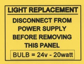
57 LIGHT REPLACEMENT DISCONNECT FROM POWER SUPPLY BEFORE REPLACING LIGHT BULBS 24v 20w LAMP PART NUMBER B UNSCREW PLATE NEXT TO LIGHT TO BE REPLACED HEX HEAD SOCKE T SCREWS 2 SLIDE FITTING OUT 3 REMOVE LIGHT FROM HOLDING SLOT AND UNCLIP FROM CABLE 4 REPLACE LIGHT AND REFIT ALL PARTS RECONNECT POWER SUPPLY AND TEST 57
58 13.0 SPARES INFORMATION 58
59 OVEN SPARES 220v. (480v IN BRACKETS) HEATERS MCB HEATERS MCB HEATERS MCB (SEE ELECTRICAL PARTS LIST ) (SEE ELECTRICAL PARTS LIST ) (SEE ELECTRICAL PARTS LIST ) CONTROL CIRCUIT MCB OVERHEAT THERMOSTAT CONTROL CIRCUIT POWER SUPPLY TOP HEAT BOTTOM HEAT CONTACTOR WATER SOLENOID (10mm pipe) WATER SOLENOID (8mm pipe) INTERIOR LIGHT (BULB) OVEN THERMOCOUPLE MAIN LED PRINTED CIRCUIT BOARD DAMPER SOLENOID B B B (220v) B (480v) B B A (up to May 2007) A (after May 2007) B B M B CANOPY FAN RELAY B FROSTED GLASS PLAIN GLASS DOOR BUMPER STOP BAKING TILE 3 ACROSS 2 ACROSS 1 ACROSS HINGE PIN RHS HINGE PIN LHS BLACK DOOR HANDLE DOOR SPRING (3 ACROSS) (2 ACROSS) WIRE ROPE SPRING RETAINING PIN PULLEY PULLEY SPINDLE DAMPER DRIVE COUPLING ELEMENT GASKET 24 v 20w DICHROIC LAMP M M M M M M M M A M M M M M M M M B
60 ELEMENT SPARES 3 ACROSS TOP HEAT ELEMENT 1.0kW TOP HEAT ELEMENT 0.6kW BOTTOM HEAT ELEMENT 0.75kW 220v 480v B (B ) B (B ) B (B ) 2 ACROSS TOP HEAT ELEMENT 0.65kW TOP HEAT ELEMENT 0.4kW BOTTOM HEAT ELEMENT 0.5kW B (B ) B (B ) B (B ) 1 ACROSS 220V TOP HEAT ELEMENT 0.325kW TOP HEAT ELEMENT 0.2kW BOTTOM HEAT ELEMENT 0.25kW B B B ACROSS 480V TOP HEAT ELEMENT 0.525kW TOP HEAT ELEMENT 0.325kW BOTTOM HEAT ELEMENT 0.40kW (B ) (B ) (B ) 60
61 14.0 ELECTRICS 61
62 PARTS LIST FOR DRAWINGS FOLLOWING 3 TRAY WIDE 220v. (480v IN BRACKETS) PARTS LIST FOR DRAWINGS FOLLOWING 2 TRAY WIDE 220v. (480v IN BRACKETS) F1 F2 F1 F3 HEATERS MCB HEATERS MCB HEATERS MCB B (B ) B (B ) B B (B ) (B ) F2 HEATERS MCB B (B ) F3 F4 CONTROL HEATERS MCB CIRCUIT MCB B B (B ) F5 OVERHEAT THERMOSTAT B F4 CONTROL TRANSFORMER MCB B F5 T1 CONTROL OVERHEAT CIRCUIT THERMOSTAT POWER SUPPLY B B (B ) K1 T1 K2 TOP HEAT CONTACTOR BOTTOM CONTROL HEAT CIRCUIT CONTACTOR POWER SUPPLY B B B (B ) K1 TOP HEAT CONTACTOR B K2 Y1 WATER BOTTOM SOLENOID HEAT CONTACTOR (10mm pipe) A (up B to May 2007) Y1 WATER SOLENOID (8mm pipe) A A (after May 2007) H1 INTERIOR LIGHT B B1 H1 INTERIOR OVEN THERMOCOUPLE LIGHT B B U1 B1 OVEN MAIN LED THERMOCOUPLE PRINTED CIRCUIT BOARD M B D1 U1 MAIN DAMPER LED SOLENOID PRINTED CIRCUIT BOARD M B D1 DAMPER SOLENOID B R1 TOP HEAT ELEMENT 0.65kW B (B ) R2 R1 TOP HEAT ELEMENT 1.0kW 0.4kW B B (B ) (B ) R3 R2 TOP HEAT ELEMENT 0.6kW 0.4Kw B B (B ) (B ) R4 R3 TOP HEAT ELEMENT 0.6kW 0.4kW B B (B ) (B ) R5 R4 TOP HEAT ELEMENT 0.6kW 0.4kW B B (B ) (B ) R6 R5 TOP HEAT ELEMENT 0.6kW 0.4kW B B (B ) (B ) R7 R6 TOP HEAT ELEMENT 0.6kW 0.4kW B B (B ) (B ) R7 R8 TOP HEAT ELEMENT 0.6kW BOTTOM HEAT ELEMENT 0.5kW B (B ) B (B ) R9 R8 BOTTOM HEAT ELEMENT 0.75kW 0.4kW B B (B ) (B ) R10 R9 BOTTOM HEAT ELEMENT 0.4kW 0.6kW B B (B ) (B ) R11 R10 BOTTOM HEAT ELEMENT 0.4kW 0.6kW B B (B ) (B ) R12 R11 BOTTOM HEAT ELEMENT 0.4kW 0.6kW B B (B ) (B ) R13 R12 BOTTOM HEAT ELEMENT 0.4kW 0.6kW B B (B ) (B ) R14 R13 BOTTOM HEAT ELEMENT 0.4kW 0.6kW B B (B ) (B ) R14 BOTTOM HEAT ELEMENT 0.6kW B (B ) CF1 CANOPY FAN RELAY B CF1 CANOPY FAN RELAY B
63 PARTS LIST FOR DRAWINGS FOLLOWING 2 TRAY WIDE 220v. (480v IN BRACKETS) F1 F2 F3 F4 F5 T1 K1 K2 Y1 H1 B1 U1 D1 HEATERS MCB HEATERS MCB HEATERS MCB CONTROL CIRCUIT MCB OVERHEAT THERMOSTAT CONTROL CIRCUIT POWER SUPPLY TOP HEAT CONTACTOR BOTTOM HEAT CONTACTOR WATER SOLENOID (10mm pipe) WATER SOLENOID (8mm pipe) INTERIOR LIGHT OVEN THERMOCOUPLE MAIN LED PRINTED CIRCUIT BOARD DAMPER SOLENOID B (B ) B (B ) B (B ) B B B (B ) B B A (up to May 2007) A (after May 2007) B B M B CF1 CANOPY FAN RELAY B R1 R2 R3 R4 R5 R6 R7 R8 R9 R10 R11 R12 R13 R14 TOP HEAT ELEMENT 0.65kW TOP HEAT ELEMENT 0.4kW TOP HEAT ELEMENT 0.4kW TOP HEAT ELEMENT 0.4kW TOP HEAT ELEMENT 0.4kW TOP HEAT ELEMENT 0.4kW TOP HEAT ELEMENT 0.4kW BOTTOM HEAT ELEMENT 0.5kW BOTTOM HEAT ELEMENT 0.4kW BOTTOM HEAT ELEMENT 0.4kW BOTTOM HEAT ELEMENT 0.4kW BOTTOM HEAT ELEMENT 0.4kW BOTTOM HEAT ELEMENT 0.4kW BOTTOM HEAT ELEMENT 0.4kW B (B ) B (B ) B (B ) B (B ) B (B ) B (B ) B (B ) B (B ) B (B ) B (B ) B (B ) B (B ) B (B ) B (B ) 63
64 PARTS LIST FOR DRAWINGS FOLLOWING 1 TRAY WIDE 220v. (480v IN BRACKETS) F1 F2 F3 F4 F5 T1 K1 K2 Y1 H1 B1 U1 D1 HEATERS MCB HEATERS MCB HEATERS MCB CONTROL CIRCUIT MCB OVERHEAT THERMOSTAT CONTROL CIRCUIT POWER SUPPLY TOP HEAT CONTACTOR BOTTOM HEAT CONTACTOR WATER SOLENOID (10mm pipe) WATER SOLENOID (8mm pipe) INTERIOR LIGHT OVEN THERMOCOUPLE MAIN LED PRINTED CIRCUIT BOARD DAMPER SOLENOID B (B ) B (B ) B (B ) B B B (B ) B B A (up to May 2007) A (after May 2007) B B M B CF1 CANOPY FAN RELAY B R1 R2 R3 R4 R5 R6 R7 R8 R9 R10 R11 R12 R13 R14 TOP HEAT ELEMENT 0.35kW (0.525kW) TOP HEAT ELEMENT 0.2kW (0.325kW) TOP HEAT ELEMENT 0.2kW (0.325kW) TOP HEAT ELEMENT 0.2kW (0.325kW) TOP HEAT ELEMENT 0.2kW (0.325kW) TOP HEAT ELEMENT 0.2kW (0.325kW) TOP HEAT ELEMENT 0.2kW (0.325kW) BOTTOM HEAT ELEMENT 0.25kW (0.4kW) BOTTOM HEAT ELEMENT 0.2kW (0.325kW) BOTTOM HEAT ELEMENT 0.2kW (0.325kW) BOTTOM HEAT ELEMENT 0.2kW (0.325kW) BOTTOM HEAT ELEMENT 0.2kW (0.325kW) BOTTOM HEAT ELEMENT 0.2kW (0.325kW) BOTTOM HEAT ELEMENT 0.2kW (0.325kW) B (B ) B (B ) B (B ) B (B ) B (B ) B (B ) B (B ) B (B ) B (B ) B (B ) B (B ) B (B ) B (B ) B (B ) 64


65 ELECTRICAL PANEL MAIN COMPONENTS TB2 K1 K2 F1 F2 F3 F4 F5 POWER SUPPLY TB3 TB1 65
66 66
67 67
68 68
69 69
70 70
71 OVEN CANOPY LAYOUT PARTS LIST F1 CANOPY FAN MCB B C1 Q1 CANOPY FAN CAPACITOR CANOPY FAN ON/OFF SWITCH B B M1 CANOPY FAN MOTOR B X1 EXTRACTION FAN SOCKET CONNECTOR EXTRACTION FAN PLUG CONNECTOR SOCKET TYPE 5669-C PLUG TYPE 5666-C CABLE, 3 CORE TYPE SO14/3 CABLE, 3 CORE TYPE SO18/3 B B B B B B MCB 2 POLE 1.0AMPS D B CAPACITOR 4-6uf 400VDB METAL FAN TYPE R2E225-AG01-21 (230V, 0.88AMP, 200W) B B
72 M1 C1 FG257 MODULAR DECK UL 08/07 RAC 72
73 X1 73
74 74


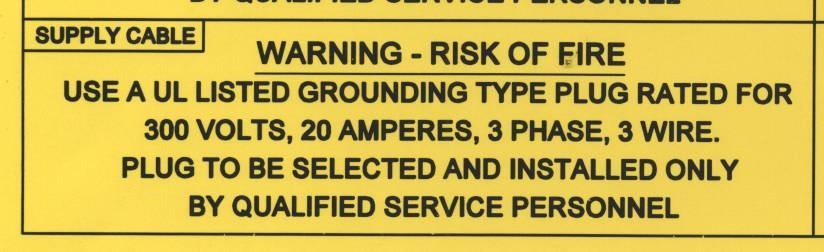
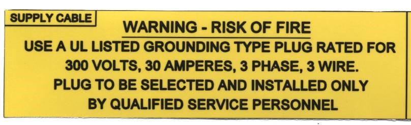
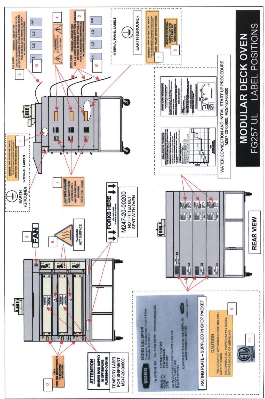
75 15.0 WARNING AND INFORMATION LABELS M M M M

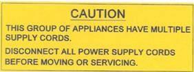

76 M M M LABEL TO WARN OF HOT SURFACES M M
77 77
78 Belshaw Adamatic Bakery Group th Street NW Suite 103 Auburn, Washington USA Tel: (USA/CANADA) Fax: Web: DISPOSAL Care should be taken when the machine comes to the end of its working life. All parts should be disposed of in the appropriate place, either recycling or other means as the law permits at the time. 78
MONO ECOTOUCH DECK OVEN
 Enter Serial No. here. In the event of an enquiry please quote this serial number. www.monoequip.com OPERATION AND MAINTENANCE MANUAL MONO ECOTOUCH DECK OVEN 1 2 IMPORTANT NOTES TO REDUCE RISK OF FIRE
MODULAR DECK OVEN. OPERATING AND MAINTENANCE MANUAL ECOTOUCH CONTROL. In the event of an enquiry please quote these serial numbers.
 In the event of an enquiry please quote these serial numbers. Enter Serial Nos. here. www.monoequip.com DECK 1 DECK 2 DECK 3 DECK 4 DECK 5 FAN (IF FITTED) MODULAR DECK OVEN OPERATING AND MAINTENANCE MANUAL
DXm MODULAR DECK OVEN
 Enter Serial Nos. here DECK 1 DECK 2 DECK 3 FAN (IF FITTED) DECK 4 DECK 5 In the event of an enquiry please quote these serial numbers. Store this document safely and ensure it is available at all times.
LED (CLASSIC) DECK OVEN
 DECK OVEN") Enter Serial No. here. In the event of an enquiry please quote this serial number. www.monoequip.com OPERATION AND MAINTENANCE MANUAL LED (CLASSIC) DECK OVEN 1 Failure to adhere to the cleaning and maintenance
Enter Serial No. here. In the event of an enquiry please quote this serial number. www.monoequip.com OPERATION AND MAINTENANCE MANUAL LED (CLASSIC) DECK OVEN 1 Failure to adhere to the cleaning and maintenance
OVEN ECOTOUCH CONTROL
 OVEN SERIAL NO. OVEN CODE 149 150 153 156 158 159 www.monoequip.com CONDENSER SERIAL No. (IF FITTED) In the event of an enquiry please quote these numbers. Bx OVEN ECOTOUCH CONTROL OPERATION AND MAINTENANCE
CONDENSER SERIAL No. (IF FITTED) In the event of an enquiry please quote these numbers.
 In the event of an enquiry please quote these numbers.") OVEN SERIAL NO. OVEN CODE 149 150 153 156 158 159 MANUAL No.Y-BX-34E CONDENSER SERIAL No. (IF FITTED) In the event of an enquiry please quote these numbers. Store this document safely and ensure it is
OVEN SERIAL NO. OVEN CODE 149 150 153 156 158 159 MANUAL No.Y-BX-34E CONDENSER SERIAL No. (IF FITTED) In the event of an enquiry please quote these numbers. Store this document safely and ensure it is
SET UP, OPERATION AND PROGRAMMING INSTRUCTIONS
 Enter Serial No. here. In the event of an enquiry please quote this serial number. www.monoequip.com SET UP, OPERATION AND PROGRAMMING INSTRUCTIONS MX ROTARY RACK OVEN ELECTRIC VERSION (STANDARD 45Kw heating
MXT ROTARY RACK OVEN SET UP AND OPERATION INSTRUCTIONS (With programming instructions)
") Enter Serial No. here. In the event of an enquiry please quote this serial number. www.monoequip.com MXT ROTARY RACK OVEN SET UP AND OPERATION INSTRUCTIONS (With programming instructions) ECOTOUCH CONTROL
Enter Serial No. here. In the event of an enquiry please quote this serial number. www.monoequip.com MXT ROTARY RACK OVEN SET UP AND OPERATION INSTRUCTIONS (With programming instructions) ECOTOUCH CONTROL
Bx OVEN SET UP AND OPERATION OF OVEN AND CONDENSER UNIT (IF FITTED) CLASSIC
 CLASSIC") www.monoequip.com OVEN SERIAL NO. OVEN CODE 149 150 153 156 158 159 180 CONDENSER SERIAL No. (IF FITTED) In the event of an enquiry please quote these numbers. Bx OVEN SET UP AND OPERATION OF OVEN AND
www.monoequip.com OVEN SERIAL NO. OVEN CODE 149 150 153 156 158 159 180 CONDENSER SERIAL No. (IF FITTED) In the event of an enquiry please quote these numbers. Bx OVEN SET UP AND OPERATION OF OVEN AND
Bx OVEN SET UP AND OPERATION OF OVEN WITH CLASSIC CONTROLLER
 Enter Serial No. here. In the event of an enquiry please quote this serial number. www.monoequip.com Store this document safely and ensure it is available at all times. Non-availability may affect the
OPERATING AND MAINTENANCE MANUAL
 Enter Serial No. here. In the event of an enquiry please quote this serial number. www.monoequip.com OPERATING AND MAINTENANCE MANUAL COMPACT SERIES 643 3 TRAY OVEN FILE 52 643 compact 3 TRAY RevA17 10-4-17
OVEN SERIAL NO. OVEN CODE CONDENSER SERIAL No. (IF FITTED) In the event of an enquiry please quote these numbers.
 In the event of an enquiry please quote these numbers.") www.monoequip.com OVEN SERIAL NO. OVEN CODE 149 150 153 156 158 159 CONDENSER SERIAL No. (IF FITTED) In the event of an enquiry please quote these numbers. Bx OVEN SET UP AND OPERATION OF OVEN AND CONDENSER
www.monoequip.com OVEN SERIAL NO. OVEN CODE 149 150 153 156 158 159 CONDENSER SERIAL No. (IF FITTED) In the event of an enquiry please quote these numbers. Bx OVEN SET UP AND OPERATION OF OVEN AND CONDENSER
CONDENSER SERIAL No. (IF FITTED) In the event of an enquiry please quote these numbers. Bx OVEN
 In the event of an enquiry please quote these numbers. Bx OVEN") OVEN SERIAL NO. OVEN CODE 149 150 153 156 158 159 MANUAL No.Y-BX-01E CONDENSER SERIAL No. (IF FITTED) In the event of an enquiry please quote these numbers. Store this document safely and ensure it is
OVEN SERIAL NO. OVEN CODE 149 150 153 156 158 159 MANUAL No.Y-BX-01E CONDENSER SERIAL No. (IF FITTED) In the event of an enquiry please quote these numbers. Store this document safely and ensure it is
OPERATING AND MAINTENANCE MANUAL
 Enter Serial No. here. In the event of an enquiry please quote this serial number. www.monoequip.com OPERATING AND MAINTENANCE MANUAL COMPACT SERIES 644 4 TRAY OVEN FILE 98 644 compact 4 tray RevA18 11-01-18
SE Series Modular Electric Stone-Hearth Deck Oven INSTALLATION & OPERATION MANUAL LBC BAKERY EQUIPMENT, INC st Ave NE Tulalip, WA 98271, USA
 SE Series Modular Electric Stone-Hearth Deck Oven INSTALLATION & OPERATION MANUAL LBC BAKERY EQUIPMENT, INC. 6026 31 st Ave NE Tulalip, WA 98271, USA Toll Free: 888-722-5686 Email: sales@lbcbakery.com
AZTEC DOUGHNUT FRYER (PLC / MK3)
") Enter Serial No. here. In the event of an enquiry please quote this serial number. www.monoequip.com OPERATING AND MAINTENANCE MANUAL AZTEC DOUGHNUT FRYER (PLC / MK3) FG059 Aztec plc RevA18 05-01-18 FILE
Enter Serial No. here. In the event of an enquiry please quote this serial number. www.monoequip.com OPERATING AND MAINTENANCE MANUAL AZTEC DOUGHNUT FRYER (PLC / MK3) FG059 Aztec plc RevA18 05-01-18 FILE
OPERATION AND MAINTENANCE MANUAL MOBILE PROVER CABINET
 Enter Serial No. here. In the event of an enquiry please quote this serial number. www.monoequip.com OPERATION AND MAINTENANCE MANUAL MOBILE PROVER CABINET FILE 20 FG132 PROVER 6-09-16 RevA16 Failure to
Installation, Operating and Servicing Instructions
 Installation, Operating and Servicing Instructions Wall Mounted Water Boiler WMB3F/B,WMB3F/W Please make a note of your product details for future use: Date Purchased: Model Number: Serial Number: Dealer:
User and Installation Instructions. Wall Mounted Water Boiler WMB3F/B and WMB3F/W IS435 ECN3461
 User and Installation Instructions Wall Mounted Water Boiler WMB3F/B and WMB3F/W IS435 ECN3461 Dear Customer Thank you for purchasing this Lincat product. With correct use and careful maintenance as described
Installation and Operating Manual Drying Cabinet
 Drying Cabinet TS-4175 WW CONTENTS THIS USER MANUAL & DATA PLATE DETAILS Page 2 IMPORTANT SAFETY INSTRUCTIONS Page 3 INSTALLATION INSTRUCTIONS Page 4 OPERATING INSTRUCTIONS Page 8 MAINTENANCE INSTRUCTIONS
TABLE TOP DOUGHNUT FRYER
 Enter Serial No. here. In the event of an enquiry please quote this serial number. www.monoequip.com OPERATION AND MAINTENANCE MANUAL TABLE TOP DOUGHNUT FRYER FG030 TABLETOP DNUT FRYER 3-4-17 Rev A17 2
Marco Beverage Systems Ltd. INSTRUCTIONS FOR MODELS
 Marco Beverage Systems Ltd. INSTRUCTIONS FOR MODELS Ecoboiler UC4L 2.4kW (1000740#) Ecoboiler UC10L 2.8kW (1000741#) Ecoboiler UC10L 5.6kW (1000742#) Ecoboiler UC4L 1.5kW 110V (1000747) Ecosmart UC4L 2.4kW
INFRARED IP55 HEATER INSTRUCTIONS FOR: MODEL:- QZWP45N 1. SAFETY INSTRUCTIONS
 INSTRUCTIONS FOR: INFRARED IP55 HEATER MODEL:- QZWP45N Thank you for purchasing a Consort Claudgen product. Manufactured to a high standard this product will, if used according to these instructions and
ivector HEATER/COOLER 2 AND 4-PIPE MODELS.
 25278 ivector Installation Guide US 02/01/2013 09:24 Page 2 ivector HEATER/COOLER 2 AND 4-PIPE MODELS. INSTALLATION, OPERATING, MAINTENANCE & AFTER SALES MANUAL JANUARY 2013, ISSUE 1 Product Serial Number:
Marco Beverage Systems Ltd.
 Marco Beverage Systems Ltd. INSTRUCTIONS FOR MODELS ECOSMART PB10, ECOSMART PB10 Hi Deck ECOSMART T10 (P/N: 1000677#, 1000678#, 1000674#) Water pressure : 5-50 psi (min.-max.)35-345 kpa (min.-max.) Marco
Operating instructions Page 12
 Operating instructions Page 12 Refrigerator with explosion-proof interior container Read the operating instructions before switching on for the first time 7082 271-00 LKEXv 910 Disposal notes The appliance
3 In 1 AIR CONDITIONER with REMOTE CONTROL MODEL NO: CA9000 PART No: OPERATION & MAINTENANCE INSTRUCTIONS
 3 In 1 AIR CONDITIONER with REMOTE CONTROL MODEL NO: CA9000 PART No: 32305600 OPERATION & MAINTENANCE INSTRUCTIONS 0304 Parts List Item Part No Description Qty 1 FT900001 Top Cover 1 2 FT900002 Filter
"WHHR125DC" Whole House Heat Recovery Unit with Low Energy DC Motor. Installation, Operating and Maintenance Instructions domestic and commercial use
 "WHHR125DC" Whole House Heat Recovery Unit with Low Energy DC Motor Installation, Operating and Maintenance Instructions domestic and commercial use Page 2 Contents Section Page Number Introduction 3 How
AHPO-6/18 GOLD PROOFER OVEN
 AHPO-6/18 GOLD PROOFER OVEN For information or technical assistance, call: TOLL FREE 1(800) 735-DUKE (3853) or 1(314) 231-1130 PN 156081R 1 of 25 TABLE OF CONTENTS MANUFACTURER S INTRODUCTION...3 INSTALLATION...4
USER MANUAL. Pharmacy Refrigerator Range. Applicable models: PSR353/PGR353 PSR273/PGR273 PSR151/PGR151
 USER MANUAL Pharmacy Refrigerator Range Applicable models: PSR353/PGR353 PSR273/PGR273 PSR151/PGR151 1 Contents Before first use 3 Positioning of refrigerator 3 Transportation and moving of refrigerator
INSTALLATION & OPERATING INSTRUCTIONS FOR THE GARLAND 1/2-SIZE ELECTRIC MOISTURE PLUS, MODEL MPOE5L
 INSTALLATION & OPERATING INSTRUCTIONS FOR THE GARLAND 1/2-SIZE ELECTRIC MOISTURE PLUS, MODEL MPOE5L FOR YOUR SAFETY DO NOT STORE OR USE GASOLINE OR OTHER FLAMMABLE VAPORS OR LIQUIDS IN THE VICINITY OF
I n s t r u c t i o n m a n u a l f o r b u i l t - i n h o o d. Model code: BORA600
 I n s t r u c t i o n m a n u a l f o r b u i l t - i n h o o d Model code: BORA600 Contact Caple on 0844 8003830 or for spare parts www.4caple.co.uk 1 Y O U R A P P L I A N C E Thank you for buying your
INSTALLATION MANUAL GUTHD2. Universal Two Way Digital Thermostatic Valve for Shower Systems
 INSTALLATION MANUAL GUTHD2 Universal Two Way Digital Thermostatic Valve for Shower Systems IMPORTANT: To ensure this product is installed properly, you must read and follow these guidelines. The owner/
Optional Optional. Min 20W, max 100W. Only resistive load or dimmable (phase control compatible) light bulb. Dimmer optional
 light bulb. Dimmer optional") Description Power Rating Remarks Control Rated Power 3 Phases Rated Voltage 3 Phases Rated Power Single Phase Rated Voltage Single Phase Frequency Switching capacity per phase Sauna temperature range Maximum
Description Power Rating Remarks Control Rated Power 3 Phases Rated Voltage 3 Phases Rated Power Single Phase Rated Voltage Single Phase Frequency Switching capacity per phase Sauna temperature range Maximum
User Instruction Manual
 User Instruction Manual Counter Top Convection Oven Please read and keep these instructions These instructions cover the Burco counter top convection oven model CTCO01, SKU 444440542 CTCO01 SKU 444440542
INSTALLATION, OPERATION and MAINTENANCE MANUAL for Cres Cor RADIANT OVENS
 FL--D 595 Heisley Road Mentor, OH 440-8 Rev. 0 (5/) Page of INSTALLATION, OPERATION and MAINTENANCE MANUAL for Cres Cor RADIANT OVENS 000-CH-SS-D 000-CH-AL-D 000-CH-SS-SPLIT-D 000-CH-AL-SPLIT-D 000-CH-SS-SPLIT-D0
USER MANUAL. Laboratory Refrigerator Range. Applicable models: LSR151 LSR288
 USER MANUAL Laboratory Refrigerator Range Applicable models: LSR151 LSR288 1 Contents Before first use 3 Positioning of refrigerator 3 Transportation and moving of refrigerator 3 Energy saving tips 4 Important
E32 CONVECTION OVEN SERVICE MANUAL -1- Revision 1/F3508
 E32 CONVECTION OVEN SERVICE MANUAL -1- WARNING: ALL INSTALLATION AND SERVICE REPAIR WORK MUST BE CARRIED OUT BY QUALIFIED PERSONS ONLY. -2- CONTENTS This manual is designed to take a more in depth look
E32M CONVECTION OVEN SERVICE MANUAL. Revision 1/F
 E32M CONVECTION OVEN SERVICE MANUAL -- WARNING: ALL INSTALLATION AND SERVICE REPAIR WORK MUST BE CARRIED OUT BY QUALIFIED PERSONS ONLY. -2- CONTENTS This manual is designed to take a more in depth look
INSTALLATION AND OPERATION MANUAL TURBO CONVECTION OVEN TCO85
 INSTALLATION AND OPERATION MANUAL TURBO CONVECTION OVEN TCO85 TCO85 Convection Oven Manual Page 1 Revision: 13 Jan 11 WARNINGS IMPROPER INSTALLATION, USE, SERVICE OR MAINTENANCE CAN CAUSE INJURY OR DEATH.
Sentinel. Kinetic MVHR and Kinetic Plus MVHR. Operation & Monitoring. Stock Ref. N
 V:\Technical\ARTWORK\Fitting & Wiring\Word Files COMPLETE\442073Q.doc Sentinel Kinetic MVHR and Kinetic Plus MVHR Operation & Monitoring Stock Ref. N 438222 Kinetic B 438222A Kinetic BS 443319 Kinetic
INSTALLATION, OPERATION and MAINTENANCE MANUAL for Cres Cor Undercounter AquaTemp HUMIDITY OVENS and CONVECTION OVENS 2000 WATTS
 Rev. (/) Page of INSTALLATION, OPERATION and MAINTENANCE MANUAL for Cres Cor Undercounter AquaTemp HUMIDITY OVENS and CONVECTION OVENS 000 WATTS COXUADE0 COXUADX0 COX8DE0 COX8DX0 COXWUADE0 COXWUADX0 Rev.
BSM60SS / BSM60WH BUILT IN MULTI-FUNCTION ELECTRIC FAN OVEN. Instruction Manual
 BSM60SS / BSM60WH BUILT IN MULTI-FUNCTION ELECTRIC FAN OVEN Instruction Manual Please read these instructions carefully before use and retain for future reference CONTENTS Safety Instructions 2 Specifications
Titon CME1 Q Plus Mechanical Extract Ventilation Unit
 Titon CME1 Q Plus Mechanical Extract Ventilation Unit Product Manual ventilation systems 2 PCT Patent Application No PCT/GB2009/000114 Contents This is the Product Manual for the Titon CME1 Q Plus Introduction...................................
Installation, Operating and Servicing Instructions. Opus 800 Electric Cook & Hold Salamander OE8306
 Installation, Operating and Servicing Instructions Opus 800 Electric Cook & Hold Salamander OE8306 Please make a note of your product details for future use: Date Purchased: Model Number: Serial Number:
User and Installation Instructions. Electric Auto-Fill Water Boilers EB3F, EB4F, EB6F, EB6TF IS339 ECN3539
 User and Installation Instructions Electric Auto-Fill Water Boilers EB3F, EB4F, EB6F, EB6TF IS339 ECN3539 Dear Customer Thank you for purchasing this Lincat product. With correct use and careful maintenance
PR-L2466W- PA. Operating Instructions. High Performance Refrigerator PR-L2466W-PA
 Operating Instructions High Performance Refrigerator PR-L2466W- PA PR-L2466W-PA Please read these instructions carefully before using this product, and save this manual for future use. See page 11 for
Sentinel Kinetic MVHR RANGE
 V:\Technical\ARTWORK\Fitting & Wiring\Word Files COMPLETE\442073 W.doc Sentinel Kinetic MVHR RANGE User Instructions Stock Ref. N 438342 Kinetic V 438222 Kinetic B Right 438222L Kinetic B Left 443319 Kinetic
30DSERIES E32D4. (Digital Operation) Installation and Operation Manual
 Installation and Operation Manual") 30DSERIES E32D4 (Digital Operation) Installation and Operation Manual 234781-12 MANUFACTURED BY Moffat Limited Christchurch New Zealand INTERNATIONAL CONTACTS AUSTRALIA Moffat Pty Limited Web: www.moffat.com.au
30DSERIES E32D4 (Digital Operation) Installation and Operation Manual 234781-12 MANUFACTURED BY Moffat Limited Christchurch New Zealand INTERNATIONAL CONTACTS AUSTRALIA Moffat Pty Limited Web: www.moffat.com.au
Digital Marine Exhaust Temperature Alarm
 Digital Marine Exhaust Temperature Alarm Model: SM007D/S INTRODUCTION COMPONENTS Marine water cooled exhaust systems are designed to withstand temperatures of up to about 120 C. However the exhaust gases
CONTROLS INSTRUCTIONS MANUAL ENGLISH
 CONTROLS INSTRUCTIONS MANUAL ENGLISH Table of Contents 1. Introduction of the Innova Controls 3 1.1 Precautions 3 2. Direction of Use 2.1 Turning on the Control Unit 4 4 2.2 Switching the Heater or Steamer
Installation, Operating and Servicing Instructions
 Installation, Operating and Servicing Instructions Electric Convection Oven ECO8, ECO9 Please make a note of your product details for future use: Date Purchased: Model Number: Serial Number: Dealer: IS
USER S MANUAL HSC-14/18/24/24A
 AIRREX AIR CONDITIONER USER S MANUAL HSC-14/18/24/24A Thank you for purchasing an AIRREX AIR CONDITIONER. BEFORE operation please read this user s manual carefully. Keep this manual readily available.
Drying Cabinet Installation and Operating Manual
 Drying Cabinet Models:- ETS-1900H ETS-1900TR CONTENTS ABOUT THE USER MANUAL Page 2 IDENTIFICATION DATA PLATE Page 2 IMPORTANT SAFETY INSTRUCTIONS Page 3 INSTALLATION INSTRUCTIONS Page 4 OPERATING INSTRUCTIONS
BOILING UNIT REDITAP. Installation and User Guide. IMPORTANT: This booklet should be left with the user after installation and demonstration
 in tap Boiling water to in tap sink Drain Valve (as high as possible) REDITAP CONNECTION SUMMARY Amp mains supply cold mains water into in tap optional filter cold water in hot water BOILING UNIT Installation
Autofill Countertop Boilers
 USER INSTRUCTION MANUAL Autofill Countertop Boilers Filtration & Non Filtration Burco Warranty 1 Year Parts 1 Year Labour 083213801 01/04/14 Contents 1.0 About your Product My Product (please complete
APPENDIX 4. Thank you for choosing the Biomega BioClave steam sterilizer. HYDRAULIC DRAWING
 Thank you for choosing the Biomega BioClave steam sterilizer. Your steam sterilizer has been CE certified and designed with durability, reliability, and safety in mind. It is your responsibility to install
Thank you for choosing
 Thank you for choosing Please read this user manual before using this oven and keep it safe for future reference. Visit our page www.electriq.co.uk for our entire range of Intelligent Electricals 1 Contents
E32 CONVECTION OVEN SERVICE MANUAL
 E32 CONVECTION OVEN SERVICE MANUAL Applies to units from S/N 40256-1- WARNING: ALL INSTALLATION AND SERVICE REPAIR WORK MUST BE CARRIED OUT BY QUALIFIED PERSONS ONLY. -2- CONTENTS This manual is designed
60cm Chimney Extractor
 60cm Chimney Extractor LAM2401 HJA2480 User & Installation Guide Contents Page Environmental note 3 IMPORTANT SAFETY INFORMATION 4 6 Specifications of your extractor 7 8 Dimensions 7 Specifications 7-8
EBAC MODEL K100 DEHUMIDIFIER OWNER S MANUAL
 EBAC MODEL K100 DEHUMIDIFIER OWNER S MANUAL Ebac Industrial Products 700 Thimble Shoals Boulevard Newport News VA 23606-2575 Telephone (757) 873-6800 Fax (757) 873-3632 Website: www.ebacusa.com INTRODUCTION
347002K/177002K/34900
 Service Manual Models: 347002K/177002K 34900/347012K Manifold Block Style Recovery/Recycling/Recharging Unit For R-12 or R-134a Only TABLE OF CONTENTS: Theory of Operation and Safety Precautions... 2 Depressurizing
16 XD Mk2 Inset Electric Fire
 16 XD Mk2 Inset Electric Fire B-1005344 Packing Checklist Electric Fire Remote Control Handset 2 x AAA Batteries Log Set Ember Ice Crystal Set Instruction Manual Fascia IMPORTANT PLEASE READ THESE INSTRUCTIONS
INTEGRA PLUS ABC. 230V~ 50Hz. Stock Ref. N. Installation and Wiring Instructions IPX2
 INTEGRA PLUS Installation and Wiring Instructions Stock Ref. N INTEGRA PLUS 437666 230V~ 50Hz ABC PLEASE READ INSTRUCTIONS IN CONJUNCTION WITH ILLUSTRATIONS. PLEASE SAVE THESE INSTRUCTIONS. IPX2 VENT-AXIA
BWTC6510GL Cooker Hood 60 cm Glass cooker hood in stainless steel. BWTC9510GL Cooker Hood 90 cm Glass cooker hood in stainless steel
 User Manual for your BWTC6510GL Cooker Hood 60 cm Glass cooker hood in stainless steel BWTC9510GL Cooker Hood 90 cm Glass cooker hood in stainless steel NOTE: This User Instruction Manual contains important
! WARNING To avoid risk of electrical shock, personal injury or death; disconnect power to range before servicing, unless testing requires power.
 Technical Information Electric Slide-In Range JES8850BC* JES9900BC* JES9860BC* Due to possibility of personal injury or property damage, always contact an authorized technician for servicing or repair
VR60 GLASS FROSTERS INSTALLATION AND OPERATING MANUAL PLEASE LEAVE WITH OPERATOR. VR60 Glass Froster. Series 1
 VR60 GLASS FROSTERS INSTALLATION AND OPERATING MANUAL PLEASE LEAVE WITH OPERATOR VR60 Glass Froster Series 1 Imperial Machine Company Limited Unit 1, Abbey Road Wrexham Industrial Estate Wrexham LL13 9RF
INSTANTANEOUS ELECTRIC SHOWER
 GUARANTEE / SERVICE POLICY INSTANTANEOUS ELECTRIC SHOWER GUARANTEE Designa guarantee this DS3000 product for a period of two years, from date of purchase, against mechanical and electrical defects arising
PORTABLE AIR CONDITIONER
 PORTABLE AIR CONDITIONER Model: PEL00460 1 CONTENTS Page No. Details 2 Important Safety Information 3 Product Overview 3 Positioning & Installation 4 Installation Errors 4 Control Panel 5 Screen IMPORTANT
Built-in Conventional Oven
 Built-in Conventional Oven LAM3204 User & Installation Guide using this manual Thank you for choosing LAMONA Built - In Oven. This user Manual contains important information on safety and instructions
OWNER S MANUAL. Evaporative Cooler. (English) (EXH, EZH) ILL239-D ILL1140-A FAN SPEED REMOTE CONTROL ECONOMY
 (EXH, EZH) ILL239-D ILL1140-A FAN SPEED REMOTE CONTROL ECONOMY") OWNER S MANUAL Evaporative Cooler REMOTE CONTROL AUTO COOL FAN SPEED PM ECONOMY ILL239-D ILL1140-A (English) (EXH, EZH) Introduction...4 Remote Thermostat Control...5 Wall Mounted Thermostat Control...11
OWNER S MANUAL Evaporative Cooler REMOTE CONTROL AUTO COOL FAN SPEED PM ECONOMY ILL239-D ILL1140-A (English) (EXH, EZH) Introduction...4 Remote Thermostat Control...5 Wall Mounted Thermostat Control...11
Warnings, Safety Information and Guidance
 EN SR700 SRHRV Fan TP600 Single Room Heat Recovery Ventilation Fan Unit SRC Controller TP590 Single Room Heat Recovery Ventilation Controller Unit Product Installation Manual ventilation systems Warnings,
Sentinel. Kinetic MVHR and Kinetic Plus MVHR. Operation & Monitoring. Stock Ref. N
 V:\Technical\ARTWORK\Fitting & Wiring\Word Files COMPLETE\442073S.doc Sentinel Kinetic MVHR and Kinetic Plus MVHR Operation & Monitoring Stock Ref. N 438222 Kinetic B 438222A Kinetic BS 443319 Kinetic
USER INSTRUCTION MANUAL. Autofill Wall Mount Boilers /12/14
 USER INSTRUCTION MANUAL Autofill Wall Mount Boilers EN 083272701-11/12/14 Contents 1.0 About your Product My Product (please complete this section) page 3 Introduction page 4 Warranty page 4 Important
! WARNING To avoid risk of electrical shock, personal injury or death; disconnect power to range before servicing, unless testing requires power.
 Technical Information Electric Slide-In Range JES9750BA* JES9860BA* Due to possibility of personal injury or property damage, always contact an authorized technician for servicing or repair of this unit.
Drying Cabinet Installation and Operating Manual
 Drying Cabinet Installation and Operating Manual Model:- ECO Dryer 2.0 HP Heat Pump Technology CONTENTS THIS USER MANUAL 3 DATA PLATE DETAILS 3 ADVICE ON SAFE OPERATION 3 DESCRIPTION OF THE CABINET 4 AIR
HI-LINE RC & HI-LINE RC Heater/Cooler Models: 7-4, 10-6, 15-10, Installation, Operating, Maintenance and After Sales Manual.
 Installation, Operating, Maintenance and After Sales Manual. HI-LINE RC & HI-LINE RC Heater/Cooler Models: 7-4, 10-6, 15-10, 20-14 heatingthroughinnovation. Product Serial Number: Please leave this manual
EDD61 & EDD91 Extractors
 EDD61 & EDD91 Extractors Installation, Use and Maintenance Customer Care Department The Group Ltd. Harby Road Langar Nottinghamshire NG13 9HY T : 01949 862 012 F : 01949 862 003 E : customer.care@cda.eu
VF X Series. User Manual. SKOPE Vertical Freezer. MAN11137 Rev. 1.1 Sep VF650X
 VF X Series SKOPE Vertical Freezer MAN11137 Rev. 1.1 Sep. 2016 VF650X SKOPE Warranty Protection Register now for peace of mind It s quick and simple. Take a few minutes to register your SKOPE product and
Series 4. Rotating rack oven Fuel-oil / Gas
 Series 4 Rotating rack oven Fuel-oil / Gas Designed for confectioners as well as bakers, the hi-tech features of the Series 4 rotating rack ovens guarantee real benefits: - Extremely compact - Offers an
COS-101 NON SELF FLUSHING COMBI REPLACEMENT PARTS LIST
 COS-101 NON SELF FLUSHING COMBI REPLACEMENT PARTS LIST EFFECTIVE FEBRUARY 16, 2012 Superseding All Previous Parts Lists. The Company reserves the right to make substitution in the event that items specified
BWT6.3GL Cooker Hood 60 cm Glass chimney hood
 User Manual for your BWT6.3GL Cooker Hood 60 cm Glass chimney hood NOTE: This User Instruction Manual contains important information, including safety & installation points, which will enable you to get
PROF. RANGE COOKER MODEL: EPRC-A6456GE(SS) Owner s Manual Please read this manual carefully before operating your set. Retain it for future reference.
 Owner s Manual Please read this manual carefully before operating your set. Retain it for future reference.") PROF. RANGE COOKER MODEL: EPRC-A6456GE(SS) Owner s Manual Please read this manual carefully before operating your set. Retain it for future reference. Record model number and serial number of the set.
PROF. RANGE COOKER MODEL: EPRC-A6456GE(SS) Owner s Manual Please read this manual carefully before operating your set. Retain it for future reference. Record model number and serial number of the set.
INSTRUCTIONS FOR USE. To make the most of your new oven, read the user's instructions carefully and keep them on hand for consultation in the future.
 INSTRUCTIONS FOR USE INSTALLATION...4 SAFEGUARDING THE ENVIRONMENT... 7 IMPORTANT NOTES... 7 BEFORE USING THE OVEN... 8 OVEN ACCESSORIES... 9 CARE AND MAINTENANCE... 10 TROUBLESHOOTING GUIDE... 12 AFTER
EZT90BL Extractor. Installation, Use and Maintenance.
 EZT90BL Extractor Installation, Use and Maintenance Customer Care Department The Group Ltd. Harby Road Langar Nottinghamshire NG13 9HY T : 01949 862 012 F : 01949 862 003 E : customer.care@cda.eu W : www.cda.eu
Installation, Operating and Servicing Instructions
 Installation, Operating and Servicing Instructions Opus 700 Electric Pasta Boiler OE7701, OE7702 Please make a note of your product details for future use: Date Purchased: Model Number: Serial Number:
BSF60WH / BSF60SS BUILT IN ELECTRIC FAN OVEN. Instruction Manual. Please read these instructions carefully before use and retain for future reference
 BSF60WH / BSF60SS BUILT IN ELECTRIC FAN OVEN Instruction Manual Please read these instructions carefully before use and retain for future reference SAFETY INSTRUCTIONS Important: This appliance is not
OWNER S MANUAL HIGH WALL INVERTER. (English) (BSHVD1S SERIES)
 (BSHVD1S SERIES)") OWNER S MANUAL HIGH WALL INVERTER (English) (BSHVD1S SERIES) IMPORTANT As with any product that has moving parts or is subject to wear and tear, it is VERY IMPORTANT that you maintain your air conditioner
OWNER S MANUAL HIGH WALL INVERTER (English) (BSHVD1S SERIES) IMPORTANT As with any product that has moving parts or is subject to wear and tear, it is VERY IMPORTANT that you maintain your air conditioner
CROWN WATER HEATERS CPU10 - CPU15 CPOS10 - CPOS15
 CROWN WATER HEATERS CPU10 - CPU15 CPOS10 - CPOS15 COMPACT PLUS 10 and 15 Litre Unvented Under and Over Sink Water Heater INSTALLATION AND USER GUIDE 1 DIMENSIONS 10L - 250mm 15L - 310mm 100mm 80mm 410mm
HWD-2110 Hot Water Dispenser
 User s Guide t f Touch Function Selector Technology HWD-2110 Hot Water Dispenser. NOTICE TO INSTALLER: Please leave this book with the machine. Temperature On Demand US design patent applied for. Other
Overview JUG CLAMPING LEVER JUG HUSK DRAWER SAFETY MICRO SWITCH TOUCHPAD ON/OFF SWITCH LED DISPLAY TEMPERATURE CONTROL (IF FITTED) FUSE HOLDER
 FUSE HOLDER") Roastilino Overview JUG CLAMPING LEVER JUG HUSK DRAWER SAFETY MICRO SWITCH TOUCHPAD ON/OFF SWITCH LED DISPLAY TEMPERATURE CONTROL (IF FITTED) FUSE HOLDER FAN AIR INTAKE Preparing for Installation Requirements
Roastilino Overview JUG CLAMPING LEVER JUG HUSK DRAWER SAFETY MICRO SWITCH TOUCHPAD ON/OFF SWITCH LED DISPLAY TEMPERATURE CONTROL (IF FITTED) FUSE HOLDER FAN AIR INTAKE Preparing for Installation Requirements
VERTICAL COOKING PRECISIO/PRECIJET COMBI OVEN PRECISIO/ PRECIJET OVENS S.A.V. MAINTENANCE AND REPAIR
 VERTICAL COOKING S.A.V. PRECISIO/ PRECIJET OVENS MAINTENANCE AND REPAIR 27/03/2012 PPS-3BEFM10PC GENERAL Tools Every time this symbol appears, it is imperative to have the appropriate tool in order to
BUILT-IN OVEN MODEL: EBO-D7080D(SS) Owner s Manual Please read this manual carefully before operating your set. Retain it for future reference.
 Owner s Manual Please read this manual carefully before operating your set. Retain it for future reference.") BUILT-IN OVEN MODEL: EBO-D7080D(SS) Owner s Manual Please read this manual carefully before operating your set. Retain it for future reference. Record model number and serial number of the set. See the
BUILT-IN OVEN MODEL: EBO-D7080D(SS) Owner s Manual Please read this manual carefully before operating your set. Retain it for future reference. Record model number and serial number of the set. See the
Installation Instructions / User s Manual TSTAT0406 and TSTAT0408
 997-060180-5 Installation Instructions / User s Manual TSTAT0406 and TSTAT0408 4 HEAT 2 COOL DUAL FUEL TSTAT0406 & TSTAT0408-4 WIRE CAPABLE THERMOSTAT (NAXA00201DB Daughter Board sold separately) LEFT
Dear customer For optimum results read your user s manual Terms of warranty The warranty does not include... HOUNÖ A/S
 Dear customer, 1 Congratulations on the purchase of your new HOUNÖ oven. You are now the owner of one of the leading oven products on the market. All HOUNÖ products are currently subjected to intensive
Air Comfort. Installation instructions (English) A
 A") Air Comfort Installation instructions (English) WWW.BRINKAIRFORLIFE.NL 614788-A This appliance may be used by children as of 8 years of age, persons of reduced mental or physical capacities and those of
Air Comfort Installation instructions (English) WWW.BRINKAIRFORLIFE.NL 614788-A This appliance may be used by children as of 8 years of age, persons of reduced mental or physical capacities and those of
90cm Chimney Extractor
 90cm Chimney Extractor LAM2412 Stainless Steel LAM2413 Black Instructions and Installation www.howdens.com/appliance-registration See back page for product serial number LAMONA Appliances Dear Customer,
CAUTION. Installation Manual
 System Controller SC-301-6M CAUTION Installation Manual In order to use this product safely, read this installation manual carefully and follow the installation instructions. Potential dangers from accidents
Flopurge TS. Operation Manual
 Flopurge TS Operation Manual Part Number 079-0204 Spectron Gas Control Systems United Kingdom Unit 4, Herald Court, University of Warwick Science Park, Coventry, CV4 7EZ +44 (0)24 7641 6234 sales@spectron-gcs.com
Ecoboiler T20 & T30 SERVICE MANUAL. Marco Beverage Systems Ltd. 63d Heather Road, Sandyford Industrial Estate, Dublin 18, Republic of Ireland
 Ecoboiler T20 & T30 SERVICE MANUAL Marco Beverage Systems Ltd. 63d Heather Road, Sandyford Industrial Estate, Dublin 18, Republic of Ireland Ireland Tel: (01) 295 2674 Ireland Fax: (01) 295 3715 UK Tel: