BOILER CLASS 5, 5A/5B LICENSE EXAMINATION STUDY GUIDE
|
|
|
- Maurice Ray
- 5 years ago
- Views:
Transcription
1 STATE OF OREGON DEPARTMENT OF CONSUMER AND BUSINESS SERVICES BUILDING AND CODES DIVISION BOILER CLASS 5, 5A/5B LICENSE EXAMINATION STUDY GUIDE 1
2 General Information for all Licensees The following study guide is to be used to assist you in preparing for the questions on the State of Oregon Boiler Licensing Exams. This is not an extensive listing of knowledge expected from a Qualified Certified Person. Where there are general discussions of ASME, NBIC, and NFPA Code requirements or of Oregon Administrative Rules or statutes, the study guide is not controlling: the applicable code, rule or statute is the final authority. The exam questions are randomly selected from a set of over 400 questions that cover administrative rules, ASME, NBIC and NFPA Codes, materials, math, drawing, repairs, physical science, safety, trade knowledge and welding for Class 4 and Class 5 candidates. The exam questions are based upon the knowledge and experience that is expected of candidates for the Class certification being attempted. The rules for licensing of persons installing, altering or repairing boilers or pressure vessels are listed in ORS through ORS Requirements for each Qualified Certified Person who can be licensed to install, alter or repair boilers, pressure vessels and pressure piping in the State of Oregon are listed in OAR These consist of Class 2, Class 3, Class 4, Class 5, Class 5-A and Class 5-B. The Class 1 Trainee/Helper and Class 6 Welder are not required to take and pass the Oregon Boiler License Exam to be certified. The exam covers the Oregon Revised Statutes and the Oregon Administrative Rules for boilers and pressure vessels but this study guide does not cover those administrative rules. These administrative rules may be printed off the web site for review and are available on line at: Boiler Statutes: Oregon Revised Statutes (ORS) to Boiler Administrative Rules: Oregon Administrative Rules(OAR) through The 2008 Oregon Boiler and Pressure Vessel Specialty Code containing the minimum safety standards for boilers, pressure vessels, pressure piping, nuclear components, parts, items, and repair and alteration procedures follow: (1) ORS to and OAR chapter 918, division 225; (2) The Boiler and Pressure Vessel Code of The American Society of Mechanical Engineers (ASME), 2007 Edition as published, including Section I; Section II, Parts A, B,C and D; Section IV; Section V; Section VIII, Division 1, 2 and 3; Section IX; and Section X. (3) The 2007 Edition of the ANSI/ASME B31.1 Power Piping Code. (4) The 2006 Edition of the ANSI/ASME B31.3 Process Piping Code. (5) The 2006 Edition of the ANSI/ASME B31.5 Refrigeration Piping Code. (6)The 2004 Edition of the ANSI/ASME B31.9 Building Service Piping Code. 2
3 (7) The 2007 Edition of the National Board Inspection Code (NBIC) ANSI/NB 23; (8) The 2007 Edition of NFPA 85, Boiler and Combustion Systems Hazards Code; and (9) The 2006 Edition of ASME CSD-1, Controls and Safety Devices for Automatically Fired Boilers. The ASME Codes listed above are codes of construction and list the allowable design, materials, construction and installation of Code items. The NBIC lists the installation requirements and the permissible repairs to Code items. This study guide will summarize sections of the above codes and discuss trade practices to assist in passing the Boiler license exam. For a more complete understanding of the above Codes, refer to the individual Code sections. Class 5 Class 5 Pressure Piping Mechanic. A person holding this license may fabricate, install, alter and repair pressure piping; install boilers and pressure vessels by attachment of piping connections; and install, assemble and repair cast iron sectional boilers. Applicants shall: 1. Have a minimum of 2,000 hours of experience performing pipe-welding or brazing on B31 pressure piping and 2,000 hours of experience performing work on pressure piping. Experience must be verified as established in OAR division 30; and 2. Pass an examination testing the applicant's knowledge of: A. American Society of Mechanical Engineers Boiler and Pressure Vessel Code, Sections I, II, IV, V, VI, VII, VIII, IX, CSD-1 and B 31 Pressure Piping; B. Structural and mechanical blueprints with the ability to interpret specifications; C. Pressure piping systems and controls; D. Boiler and Pressure Vessel Laws, ORS to and OAR chapter 918, division 225; and E. Welding, brazing, chemical bonding procedures, heat treatment, metallurgy and other procedures applicable to pressure piping systems. Class 5-A Class 5-A Process Piping Mechanic License. A person holding this license may fabricate, install, alter or repair B31.3 process piping. Applicants shall: 3
4 1. Have a minimum of 2,000 hours of experience performing pipe-welding or brazing on B31.3 process piping and 2,000 hours of experience performing work on pressure piping. Experience must be verified as established in OAR division 30; and 2. Pass an examination testing the applicant's knowledge of: A. American Society of Mechanical Engineers Boiler and Pressure Vessel Code, Section B31.3; B. Structural and mechanical blueprints with the ability to interpret specifications; C. Pressure piping controls; D. Boiler and Pressure Vessel Laws, ORS to and OAR chapter 918, division 225; and E. Welding, brazing, chemical bonding procedures, heat treatment, metallurgy and other procedures applicable to pressure piping systems. ASME B31.3 Category M piping is designated as lethal service piping. Category M piping is designated by the system owner and must be inspected by a Certified Process Piping Inspector that is employed by the piping system s owner. All piping systems should be designed with consideration of vibration, thermal and seismic loadings. Class 5-B Class 5-B Refrigeration Piping Mechanic License. A person holding this license may fabricate, install, alter or repair B31.5 refrigeration piping. Applicants shall: 1. Have a minimum of 2,000 hours of experience performing pipe-welding or brazing on B31.5 refrigeration piping and 2,000 hours of experience performing work on pressure piping. Experience must be verified as established in OAR division 30; and 2. Pass an examination testing the applicant's knowledge of: A. American Society of Mechanical Engineers Boiler and Pressure Vessel Code, Section B31.5; B. Structural and mechanical blueprints with the ability to interpret specifications; C. Pressure piping controls; 4
5 D. Boiler and Pressure Vessel Laws, ORS to and OAR chapter 918, division 225; and E. Welding, brazing, heat treatment, metallurgy and other procedures applicable to pressure piping systems. Piping systems for refrigeration piping may utilize materials that meet the ASME B31.5 Code. These materials may be reclaimed provided the piping is properly identified. Bending and cold springing to align pipe is allowed providing the finished piping surface is free of cracks and buckles. Fittings used may include bell and spigot type. Toxic service fluids cannot use cast or malleable iron fittings. Piping designs for exposed piping systems must include the effects of wind loading. All pressure piping systems shall be designed for seismic loadings. ASME Section IX covers brazing requirements. A3 and B3 refrigerant piping butt and miter groove welds require both visual and 5% radiographic inspection. Pressure testing of refrigeration piping systems shall be at least 110% but not more than 130% of the system design pressure. Pressure Vessel Installations Piping Attachments Flanged Attachments- The bolts in a flanged connection must exhibit full thread engagement. This means that bolts shall engage so that the threading goes completely through the nut. Follow manufacturers recommendations when tightening flange bolts. Threaded fittings- Completed thread fittings must leave at least two threads exposed. In addition, different sized fittings have a minimum number of threads that must be engaged in the fitting. Minimum thread engagement in threaded fittings are as follows: Under 1-1/2 NPS 4 threads 1-1/2 & 2 NPS 5 threads 2-1/2 to 4 NPS 7 threads 5 & 6 NPS 8 threads 8 NPS 10 threads 10 NPS 12 threads 12 NPS 13 threads EXAMPLE: A 2 NPS fitting must have at least 5 threads engaged and must leave at least 2 threads exposed. Piping Materials- Piping materials for ASME applications must be listed in ASME Section II. ASME-listed piping materials must have identifying marks recording the piping type, manufacturer and heat numbers of the batch for traceability. 5
6 When ASME piping materials are cut, the identifying numbers must be transferred to the cut pieces. Since coatings would make the identifying markers unreadable, painting prior to installation or galvanizing is not allowed. Some non-metallic piping, including plastic piping, is listed in ASME Section II and is allowed in ASME B31.9, Building Service Piping, but the use of PVC plastic pipe is not allowed. PVC piping may not be used because it may fracture under pressure and will become brittle when cold. In air compressors, PVC could be affected by compressor oils in the air stream. ASME B31.9, Building Service Piping covers piping systems operated at pressures up to 150 psi. Used piping- Used piping and piping fittings may only be used after thorough cleaning and inspection by an authorized inspector. If identifying marks are not clearly visible, the inspector may require mechanical and/or chemical testing to verify the composition of the material. Pressure testing of vessels and piping systems- Leak testing of pressure vessels and piping systems may be required by an inspector. The To safely pressurize a system for a leak test: the system s pressure must be gradually increased to a required test pressure (provided by the inspector) the test pressure must be maintained for a designated period of time, generally between 10 to 20 minutes. If water is used to perform the leak test, the metal temperature must be at least 60 o F to assure the vessel is not thermally stressed. For personnel safety, the temperature should not exceed 120 o F. If air or nitrogen is used to perform the leak test, the test will be performed at lower pressures and must first be approved by an inspector. Air and nitrogen under pressure have high kinetic energy and could create an explosion if there is a rupture. Piping weight and hydrotests- When installing piping, the additional weight that will be applied during a hydrotest must be taken into consideration. Even air piping must be installed so that it can bear the weight that will be applied during a hydrotest. Thus, an installer must know the weight of the entire piping system in order to properly design and select pipe supports and hangers. To know the weight of a section of pipe that is filled with water, you must know: The weight of the pipe per foot of run The volume inside the pipe The weight of the water required to fill that volume Figuring out this information sometimes requires the use of basic math and the memorization of some basic facts about the weight of water and the volume of water within an area. 6
7 Mathematical terms related to circles: Diameter Circumference Radius For the purposes of using math in the field, (pi) is rounded off to be 3.14 You should also know how to convert fractions into decimals: To convert ¾ into a decimal, divide 3 by 4, which would give you.75 You can use a calculator to do this, or you could do it long hand by adding a decimal point and zero to the top half of the fraction (dividing 3.0 by 4) and putting your answer to the right of the decimal point your answer. ½ =.50 [1.0 2 =.50] 1/3 =.333 [1.0 3 =.333] 4/5 =.80 [4.0 5 =.80] 7/8 =.875 [7.0 8 =.875] Area of a circle The formula for calculating the area of a circle is: Radius x Radius x 3.14 = Area ( r 2 = Area) Example- For a 6 inch diameter pipe, the radius equals one half of the diameter, 3 inches 3 inches x 3 inches x 3.14= 28.3 square inches Circumference of a circle The formula for calculating the circumference of a circle is: Diameter x 3.14= Circumference 2 7
8 ( d=circumference) Example- For a 6 inch diameter pipe, 6 inches x 3.14= inches in circumference Also, with pipes there are two circumferences: the inner circumference (the circle that is on the inside of the pipe) the outer circumference (the circle that is on the outside of the pipe) As pipes get larger there can be a substantial difference between the inner circumference and the outer circumference. To calculate the inner circumference you would use the diameter of the inside of the pipe. To calculate the outer circumference, your diameter would be the diameter from the inside of the pipe plus the thickness of the pipe. Example- The outer circumference of a ½ thick pipe with a 6 inch inner diameter would be: 7 inches (6 inner diameter plus ½ thickness on both sides) x 3.14= inches Volume of a cylinder (or pipe) The formula for calculating the volume of a cylinder is: Area x Length = Volume Example- For a 6 inch pipe with a 24 inch run (length): 28.3 inches x 24 inches = cubic inches of volume Calculating gallons of water per cubic inch The formula for knowing how much water is in a volume of pipe is: One gallon of water = 231 cubic inches of piping We know from the previous calculations that a 6 inch pipe that runs 24 inches pipe holds cubic inches of water volume (volume in cubic inches) 231 (# of cubic inches in a gallon) = 2.94 gallons Weight of water The formula for the weight per gallon of water is: One gallon of water weighs 8.34 pounds Since our 6 inch pipe that runs 24 inches holds 2.94 gallons of water we can determine the weight of the water as follows: Pressure of water 2.94 gallons x 8.34 pounds = 24.5 pounds of water 8
9 The formula to determine the pressure of water at the bottom of a column of water (for example, the bottom of a pipe or tank) is: Height of the column in feet x.434 = pressure per square inch (PSI) Example- The pressure for a 40 foot high column of water is: 40 x.434 = 17.36psi Boiling point of water and other substances - The boiling point of a liquid is the temperature at which the vapor pressure of the liquid equals the environmental pressure surrounding the liquid. A liquid in a vacuum environment has a lower boiling point than when the liquid is at atmospheric pressure. A liquid in a high pressure environment has a higher boiling point than when the liquid is at atmospheric pressure. In other words, the boiling point of liquids varies with and depends upon the surrounding environmental pressure. The normal boiling point of a liquid is the special case in which the vapor pressure of the liquid equals the defined atmospheric pressure at sea level. Example- The normal boiling point of water is 100 C/212 F Heat Capacity Specific heat capacity is the measure of the heat energy required to increase the temperature of a unit of a substance by a certain temperature. More heat energy is required to increase the temperature of a substance with high specific heat capacity than one with low specific heat capacity. The term "BTU" is used to describe the heat value (energy content) of fuels, and also to describe the power of boilers, as well as heating and cooling systems. When used as a unit of power, BTU 'per hour' is understood, though this is often confusingly abbreviated to just "BTU". 1 watt is approximately BTU/h 1000 BTU/h is approximately 293 W 1 horsepower is approximately 2,544 BTU/h A BTU is also the energy required to raise one pound of water by one degree Fahrenheit. Design Pressure All pressure containing components must be rated at a design pressure at least as high as the vessel design pressure. Piping components such as flanges and valves are typically marked with the design pressure. Valves ASME approved safety relief valves are required for every vessel 9
10 Shut off valves are not permitted on either the inlet or discharge of safety relief valves The piping on the discharge side of a safety relief valve may not be reduced down nor routed such that the flow could be restricted by pocketing that traps liquid. The discharge from the safety relief valve must be directed to a safe location. Safety relief valves must be handled carefully so as to not disturb their setting If the safety relief valve s assembly seal is not intact, the valve must be retested and recertified or the unit must be replaced. Safety relief valves can only be disassembled and set by a NBIC authorized Service Center. Valves should be positive shut off. Positive shut off valves include gate valves, ball valves, tapered cock valves and globe valves. Globe valves are directional and should be installed with the flow direction below the disc. Valves should be clearly marked as suitable for the service. For example, a water, oil gas service valve should be marked: W-O-G for water, oil and gas. Workplace Safety Pipe fitters and boilermakers are commonly exposed to potential safety hazards. General Safety Precautions When working on oxygen piping or oxygen generators, care should be taken to eliminate organic materials as these can combust when exposed to the oxygen. A simple oily rag exposed to oxygen can ignite. Oxygen storage tanks must be installed on a non oxidizing surface. Confined areas, like service pits or the inside of a boiler or pressure vessel, can lack sufficient oxygen for safe breathing. Before entering such a space: Make sure an OSHA approved confined space entry procedure is being followed. (Oxygen levels must be tested, there must be adequate ventilation, and the temperature must not be too high). Where welding is taking place there must be a trained person watching for fire and able to perform rescues and emergency medical treatment. Fires and explosions are one big risk in the work site. In order to deal with this risk safety precautions should always be followed and individuals need to know how to properly use fire extinguishers. Fire extinguishers are marked with the class of fire they are designed to be used upon: Class A Class B Class C Class D Wood, sawdust, paper, rags Flammable liquids, oils, tars and gasses Electrical equipment Combustible, self-oxidizing metals 10
11 Water hoses should only be used on Class A fires. Water can cause explosions or a worsening of the fire if it is used on a Class B, C, or D fire. Foam, CO 2 and dry powder extinguishers eliminate the oxygen from different types of fires, the following types of extinguishers are suited to the following type of fire: Class A fires, water or CO 2 extinguishers Class B fires, CO 2 or foam extinguishers Class C fires, CO 2 extinguishers or dry chemical extinguishers must be used if there is live current Class D fires, different metals require different extinguishing materials, thus the work site should have dry powder extinguishers that are appropriate for the potential fire dangers Blueprints Blueprints are generally drawn through isometric projection. Isometric projection is a mathematical method of constructing a 3 dimensional object without using perspective. Isometric projection was an attempt to make drawings more realistic. The mathematics involved mean that all lengths when drawn at 30 degrees can be drawn using their true length (in other words lines aren't shortened as with oblique drawings). An isometric drawing shows two sides of the object and the top or bottom of the object. All vertical lines are drawn vertically, but all horizontal lines are drawn at 30 degrees to the horizontal. Isometric is an easy method of constructing a reasonable '3 dimensional' images. The term isometric comes from the Greek for "equal measure", reflecting that the scale along each axis of the projection is the same (this is not true of some other forms of graphical projection). Boiler Installation Requirements ASME stamps All boilers and pressure vessels shall be installed to comply with the Oregon State Boiler and Pressure Vessel Law and must be ASME Code Stamped (unless installed to an approved International standard): Section I power boilers shall be stamped with a A, M, E, or S code stamp. Section IV hot water heating boilers and hot water supply boilers shall be stamped with an H or HLW code stamp. Unfired pressure vessels shall be stamped with a U or UM code stamp. Welded boiler external piping over NSP 2, if installed by other than the boiler manufacturer, must be stamped with a S or PP code stamp. Notifying Authorized Inspector before Work Begins 11
12 All installation/repair permits issued by the State of Oregon Building Codes Division require that the authorized inspector be notified prior to commencement of work. It is imperative that the inspector is contacted as some installations and most repairs require inspections before much progress is made on a project. Work done prior to the approval of the inspector may have to be removed and re-done. Controls and Safety Devices for Automatically Fired Boilers (CSD-1) ASME CSD-1, Controls and Safety Devices for Automatically Fired Boilers applies to all boilers under 12,500,000 BTU. National Fire Protection Association (NFPA) requirements apply to boilers 12,500,000 Btu and over. Control devices are required to be tested and certified by the Underwriters Laboratory (UL). Rebuilt and repaired devices are not allowed as their certification is no longer valid. All electrical components shall be mounted in the appropriate National Electrical Manufacturers Association (NEMA) enclosures. All wiring for boilers shall be rated for the maximum temperature to which they may be exposed. Boiler Clearances Installation of boilers in newly constructed boiler rooms shall have: A minimum side clearance of 36 in. on each side and adequate room to all for removal and installation of boiler tubes. The top clearance must be at least 36 in., unless there is a top manway where a top clearance of 84 in. is required. Boilers with bottom openings shall have at least 12 in. bottom clearance. Boilers in battery (connected to each other) shall have a minimum of 48 clearance between the boilers. Boiler Room Exits Boiler rooms shall provide two means of exit when the boiler room exceeds 500 sq. ft. and the boilers have a capacity of 1,000,000 Btu/hr or greater. Multiple Boiler Installations For multiple boiler installations: Steam boilers shall all be installed such that all boilers have the same low water operation level. High pressure steam outlet stop valves used where the boilers have man-ways and a common header require two outside screw and yoke rising stem block valves. A stop valve shall be installed in each supply and return connection for each boiler. 12
13 For high pressure steam boilers with man-ways connected to a common header, the boiler external piping ends at the second block valve. Diligence must be exercised to assure that the boiler you are working is locked out and tagged out. Each boiler shall have temperature, pressure and level limit controllers and not rely on safety controllers that are located on a common header. Steam boilers operated in battery shall not be installed closer than 48 inches from each other. CSD-1 The operation of control systems and safety devices installed as required by CSD-1 shall be tested by the installing contractor prior to release to the owner/user. Installing contractors shall provide a written report for each installation that shall list: 1) each control and safety device installed in accordance with CSD-1 2) name of the manufacturer and model number of each device 3) operational tests performed The above items shall be verified by signature of an authorized representative of the installing contractor on this report. This report shall be made available to the authorized inspector prior to final inspection. The installing contractor shall provide to the owner/user pertinent operating, testing, servicing and cleaning instructions for the controls and safety devices together with complete wiring and piping diagrams and a written precaution that operating, testing and servicing may only be performed by qualified individuals. Valves in General All valves or cocks shall have adjustable stem packing glands and provide tight closure. Valves shall indicate when open by either a lever in cock valves or a rising stem for gate valves. No shut off or other valves are to be placed between the boiler and the pressure controllers, nor should valves be placed on the discharge side of a pressure relieving valve. Discharge piping must be directed to a safe location and the weight of that discharge piping cannot be supported on a valve, as this could cause distortion of the valve mechanism and affect the performance of the valve. The purpose of stop check valves on the main boiler steam discharge line to a steam header for multiple boilers is to prevent steam from entering a cold boiler. Cold water should never be introduced into a hot boiler. Feedwater piping should be located such that the addition of water is not onto a hot boiler surface. 13
14 Water hammer is a pressure surge or wave resulting when a fluid in motion is forced to stop or suddenly change direction. Water hammer commonly occurs when a valve is closed suddenly at an end of a piping system, and a pressure wave develops in the pipe. Water hammer in piping or a vessel can cause a rupture. The hammering sound heard is the result of liquid water traveling ahead of expanding steam. The pressure wave can exceed the safe allowable pressure in the pipe or vessel. Pressure Relieving Valves Pressure relieving valves are generally spring controlled valves that pop open at a preset pressure to assure that the vessel cannot over-pressurize. Any pressure relieving device used on an ASME boiler or pressure vessel must be marked with an ASME V, HV or UV code stamping. Section I power boilers that exceed 500 sq. ft. of heating surface must have 2 or more safety valves. The valves shall be sized such that the relieving capacity will not allow the pressure of the boiler to exceed 106% of the maximum allowable working pressure (MAWP). Example: A 750 square foot boiler with a MAWP of 150 pounds per square inch would require 2 safety valves. The two valves, in combination, could not allow the boiler to exceed 159 psi (106% of the MAWP) An electric boiler with a power input of more than 1100 kw must have 2 or more safety valves. The valves shall be sized such that the relieving capacity will not allow the pressure of the boiler to exceed 106% of the maximum allowable working pressure (MAWP) Example: A 750 square foot boiler with a MAWP of 150 pounds per square inch would require 2 safety valves. The two valves, in combination, could not allow the boiler to exceed 159 psi (106% of the MAWP) Section IV steam boilers cannot have individual safety valves that are larger than 4 NPS (4 nominal pipe size) Steam boilers must use a safety valve that is designed for steam only Section IV heating boilers cannot have individual safety valves that are larger than 4 NPS. Section IV boiler valves shall be made of ASME Code Section II approved materials or an ASME Code accepted standard, such as ANSI. The minimum pressure/temperature rating shall at least equal the pressure limits stamped on the boiler and equal to the boiler design temperature but not less than 250 o F. Hot water boilers must have a relief valve designed for water use. The safety relief valve shall be set to relieve at or below the MAWP of the boiler 14
15 Section VIII pressure vessels use a valve with an enclosed spring that is designed for either liquid or gas applications. Air is a gas. All spring controlled pressure relieving valves must be mounted with the valve stem in a vertical position, close to the vessel (for boilers the device must be mounted directly to the boiler) Steam boilers must have the safety valves located at the top of the boiler and above the normal high water operation level Steam boilers shall have at least one steam pressure control device that will shut off the fuel supply when the steam pressure reaches a preset operating pressure. An additional pressure controller is required that will prevent generation of steam pressure that exceeds the MAWP of the boiler. This high limit pressure controller shall have a safety shutdown and lockout with a manual reset. Steam boilers also require a siphon tube or other means that maintains a water seal between the boiler and the pressure controllers. Residential installations do not require the lockout feature on the high limit pressure controller. Steam supply connections to a pressure control shall not be less than the following: Non-ferrous materials NPS ¼ up to 5 ft. length NPS ½ over 5 ft. length Ferrous materials NPS ½ up to 5 ft. length o NPS 1 over 5 ft. length Temperature and Pressure Safety Valves Hot water service vessels with a temperature limit of 210 o F, such as HLW hot water storage tanks, some coil type boilers and hot water heaters shall utilize a temperature and pressure safety valve (T&P). Gages T & Ps have a bi-metallic probe that opens the valve prior to the boiling point of water. T & Ps may be mounted in a horizontal position but must be located such that the probe is always immersed in water at the normal operating liquid level and the outlet pointed down. The horizontal mounting cannot be lower than 4 from the top of the vessel and cannot have more than 4 of interconnecting piping. The discharge must be self draining. All boilers shall have a shut off cock between the boiler and a gage with a lever handle that is parallel with the supply line to the gage when the cock is open Section I steam boilers shall: 15
16 Have a pressure gage that reads approximately double the relief setting of the safety relief valve and never less than 1 ½ times the relief safety setting. Have a siphon tube that maintains a water seal between the boiler and the gage. The minimum size for the siphon if used shall be ¼ inside diameter. Have connections to the boiler, except the siphon, that are not less than ¼ NPS, but where steel or wrought iron pipe or tube is used, they shall not be less than ½ inside diameter. Section IV hot water heating and hot water supply boilers require a temperature gage or thermometer located in the liquid portion of the boiler near or at the outlet of the boiler. Section I and Section IV steam boilers require water level indicators. Section I boilers must have a visible gage that is mounted with the lowest visible water level at least 2 above the lowest permissible water level. Section IV steam boilers must have a visible gage that is mounted with the lowest visible water level at least 1 above the lowest permissible water level. Multiple gage glasses must have a 1 overlap in visible water level. Connections to and from the water column must be a minimum NPS 1 with the boiler connections having the upper connection in the steam section of the boiler and the lower in the water section. The drain on the water column must be at least NPS ¾. Gage glass connections must be at least NPS ½. A cross or tee pipe fitting shall be used at 90 o turns to facilitate cleaning. Water Level Controls Water level controls vary with the type of boiler. Commercial installations of steam boilers require two low water fuel cutoffs. o One cutoff is mounted to actuate before the other cutoff o The lower cutoff unit must actuate prior to loss of visible water in the sight glass o The lower cutoff must shut down the energy to the burner AND lock out as well. There is to be a manual reset on the locking out unit. o The units on steam boilers must be located on separate water columns with no intervening valves and separate attachments to the boilers water section. There may be a common steam section attachment. o Cross or tee pipe fittings shall be used at 90 o turns to facilitate cleaning. o Controls should be cleaned annually. Coil type hot water heating boilers that require forced circulation shall have a flow sensing switch that will prevent operation of the burner when there is an inadequate flow rate. The flow switch shall have a testing circuit that will automatically restore to service after testing is complete. Hot water heating boilers shall have a temperature actuating control to shut off the fuel supply when the water reached a preset operating temperature. A second temperature control is required to limit the water temperature to the maximum allowable temperature; the upper set point adjustment must be fixed at the maximum allowable temperature. This 16
17 control shall cause a shut down and lockout of the boiler. The lockout feature on the high limit device is not required on residential installations. Pressure testing boilers depends upon the type of boiler. Most types of boilers are to be hydro tested by filling the boiler with water that is at least 60 o F and gradually increasing the pressure to 1-1/2 times the MAWP of the boiler. The boiler temperature should not exceed 120 o F. The pressure shall be measured by a certified gage that has a measuring range of about double the test pressure but in no case less than 1 ½ times the test pressure. Drains and Bottom Blow Down Pipes Section IV low pressure boiler drains for steam or hot water boilers shall: Be a minimum of ¾ NPS Have a valve that is pressure rated at least equal to the MAWP of the boiler, but in no case less than 30 PSI. The valve must have a minimum temperature rating of no less than 250 F Drain piping must be located at the lowest point of the boiler shell. Cast iron boilers are required to have a wash out opening that is NPS 1-1/2 for boilers with a volume more than 5 ft 3 or NPS 1 for boilers not more than 5 ft 3. Damaged cast iron boiler sections are not allowed to be brazed, welded or epoxy repaired. Code welding cannot be done on metals that have over 0.35% carbon. Cracked or eroded sections can only be replaced with a new section. Cast aluminum boilers are required to have a wash out opening that is NPS 1-1/2 for boilers with a volume more than 5 ft 3, NPS 1 for boilers from 2 ft 3 to not more than 5 ft 3 or NPS ¾ for boilers less than 2 ft 3. Section I steam boiler bottom blow down pipe fitting within the boiler external boundary shall: Be made of steel The pipe thickness shall not be less than that of a schedule 80 pipe for boilers with a maximum working pressure exceeding 100 PSI Galvanized steel pipe and fittings shall not be used for blow down pipe. Section I steam boilers with a working pressure of more than 100 PSI shall have two slow opening valves or one quick opening valve at the boiler nozzle followed by a showopening valve. Minimum size of bottom blow-off piping and valves are: 1. Square feet of heating area for Section I S Stamped boilers up to 20 Minimum NPS ½ over 20 to100 Minimum NPS ¾ above 100 Minimum NPS 1 Maximum size of blow down pipe is 2 ½ 17
18 2. Steam capacity in lbs per hr for Section IV H Stamped boilers up to 500 NPS ¾ 501 to 1250 NPS to 2500 NPS 1-1/ to 6000 NPS 1 ½ Above 6000 NPS 2 Disconnects CSD-1, CE-100 requires an electrical switch to disconnect all power to the burner controls. o This disconnect must be capable of being locked in the open position and be located on or adjacent to the boiler. o The disconnect shall remove all electrical sources of potential. Boiler installations also require a manually operated remote shut down switch outside each entry door to the boiler room. o If a boiler room door opens to the outside of the building, the switch shall be just inside the door. o Manually operated remote shut down switches shall be marked for easy identification. Vents Combustion air shall be adequate for the design of the boiler. Should vents be equipped with louvers or fans to supply combustion air, the louvers or fans must be interlocked with the burner so that flow is proven during burner operation. Boilers firing LP gas that do not comply with ANSI Z21.13 which are installed indoors, shall be equipped with safety shutoff devices or the complete shutoff type that will shut off the flow of gas to both the main burner(s) and pilot(s) in the event of a flame, pilot or ignition failure. Boilers having an input rating of 400,000 but/hr or less, with field installed gas burner assemblies and boiler units that do not comply with ANSI Z21.13/CSA 4.9 shall comply with the provisions for purging, safety control timing, action on flame failure, loss of combustion air, combustion air proving and fuel supervision given in ASME CSD-1 Table CF-1 or Table CF-2, as applicable. Gas fired boilers in excess or 400,000 btu/hr input shall meet all of the requirements of CSD-1 (Combustion Side Control) part of CF: Required lines must be vented to atmosphere shall not be connected to a common manifold and must run full size to a point of safe discharge. The terminal point shall be provided with means to prevent stoppage by foreign material, moisture or insects. 18
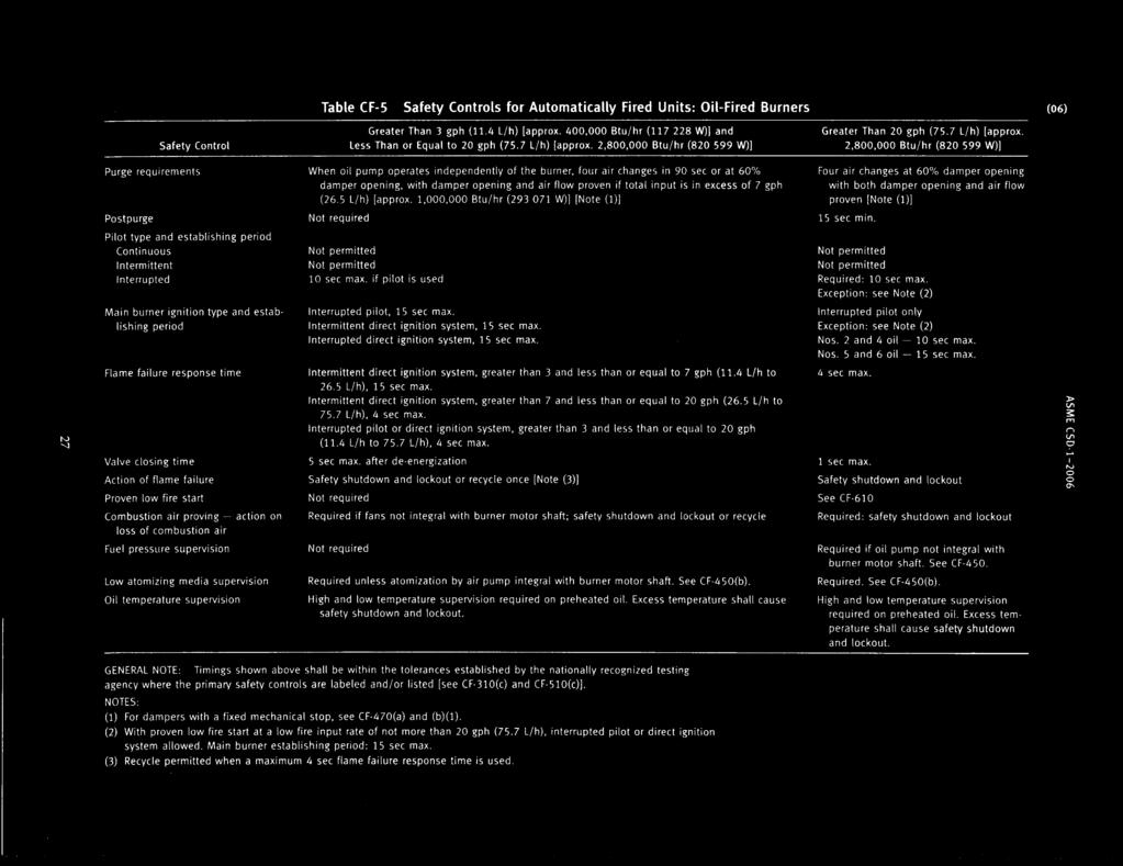
19 Supply line manually operated shut off valves for NPS 2 and larger, the valves shall be lubricated plug type with stops and the handle shall indicate clearly the on and off positions. Pilot piping shall have a similar shut off valve. For purge, post-purge, flame failure, proving and start times see ASME CSD-1, Table, CF-1, Table CF-2, Table CF-3, and Table CF-4. Oil fired boiler burners that have an input rating greater than 3 gph require: A UL 296 or a UL 726 label Supply line filters and strainers located upstream of the safety shutoff valve A pressure relief valve connected to a fuel supply line in which pressure greater than the design pressure can build up by closing any valve. The relief discharge shall be routed to the oil tank or the pump suction. For burners (except rotary cup), unless the oil pump is integral with the burners motor shaft and operates over 20 gpm, the main burner shall have a low pressure interlock switch that will cause a safety shutdown if the oil pressure falls below the manufacturers design pressure Burners with a low pressure interlock switch that will cause a safety shutdown if the atomizing air of steam falls below the manufacturer s design pressure For preheated oil system, burners shall have a high oil temperature interlock switch that will cause a safety shutdown and lockout when the oil temperature exceeds preset limits. An interlock switch to cause safety shutdown for low temperature oils that allows circulation to reestablish preset oil temperature Two approved safety shut off valves or one safety shutoff valve and a nozzle cutoff valve integral to the fuel unit shall be provided. The safety shutoff valves shall conform to the Standard for Electrically Operated Valves, UL 429. A nozzle cutoff valve shall conform to the Standard for Pumps for Oil Burning appliances, UL 343. Safety shutdowns and lockouts established upon loss of combustion air for boilers rated greater than 20 gpm. For boilers rated less than or equal to 20 gpm, where the forced or induced draft fans are not integral with the motor shaft, loss of combustion air shall shut off the burner. That each main burner assembly shall provide a primary safety control that will de-energize fuel supply upon flame loss. The primary safety control shall require manual resetting even in the event of a power loss. For purge, post-purge, flame failure, proving and start times see ASME CSD-1 and Table CF-5 Electrically heated boilers for steam or hot water service greater than 115 kw shall comply with Standard for Electric Boilers UL 834, NEC and NFPA 70. Boiler units having inputs greater than 2,500,000 Btu/hr (gas fired) or 20 gph (oil fired) shall be equipped with an interlocked damper to provide for low fire starts. 19
20 Expansion Tanks Hot water heating boilers shall have an expansion tank consistent with the capacity of the system. For systems designed for a working pressure of 30 psi, the expansion tank shall be designed for a minimum hydrostatic test of 75 psi. Expansion tanks for systems designed to operate above 30 psi, the tank shall be designed in accordance with ASME Section VIII, Division 1. Provisions shall be made for draining the tank without emptying the system, except for pre-pressurized tanks. H Stamped Boiler Expansion Tank Capacities System Volume Tank Capacities (Gallons) Gallons Pressurized Diaphragm Type Non-pressurized Type System vol. includes boiler, radiation and piping, not expansion tank. Above expansion tank capacities based upon 195 o F, fill pressure 12 psi and 30 psi operating pressure. HLW Stamped Boiler Expansion Tank Capacities System Volume Tank Capacities (Gallons) Gallons Pressurized Diaphragm Type Non-pressurized Type System volume includes boiler, radiation and piping, not expansion tank. Above expansion tank capacities based upon 180 o F, fill press 60 psi and 125 psi operating pressure. 20


21


22


23


24

25


26


27


28


29


30


31
32 A Class 4 boilermaker may do welding repairs on ASME Code boilers and pressure vessels only if employed by a firm that holds a current NBIC R Stamp Certificate and if the boilermakers welding meets the firm s welding certification program. All Code repairs shall be such that the material and repair conform to the vessel s original ASME construction code. Repairs to pressure retaining items shall not be initiated without the authorization of the inspector, who shall determine the repair methods that are acceptable. Routine Repairs- The NBIC defines four repairs as routine. Routine repairs may be accomplished with prior inspector approval. The four are: 1) Welded repairs or replacement of tubes or pipes NPS 5 and smaller, or sections thereof, where neither post weld heat treatment nor NDE other than visual inspection is required by the original code of construction. 2) The addition or repair of non-load bearing attachments to the pressure retaining items where post weld heat treatment is not required. 3) Weld buildup of wasted areas in shells and heads not exceeding 100 sq. in. or 25% of nominal wall thickness or 1/2 inch, which ever is less. 4) Corrosion resistance weld overlay not exceeding 100 sq. in. All weld repairs to pressure containing components require a pressure test to verify leak tightness integrity of the repair. Repairs- A repair is the work necessary to restore pressure retaining item to a safe and satisfactory operating condition. Some examples of repairs are: Weld repair or replacement or pressure retaining parts that have failed in a weld or base metal Weld buildup of wasted areas Addition of studs, hex steel or expanded metal for refractory lining Replacement of boiler and heat exchanger tubes where welding is involved The addition of a nozzle provided the nozzle is identical to a nozzle in the original design and is no closer than three times its diameter from another nozzle Installation of a flush patch Replacement of a slip on nozzle with a weld neck nozzle or vice-versa Steam locomotive and historic steam boiler repairs are controlled by the National Board Inspection Code (NBIC). 32
33 The NBIC allows flush patches, wasted area buildup and ground out defects repairs to be done with an alternative to post weld heat treatment. Specific preheating, maintenance of temperature throughout the repair and controlled cool down may be approved by the authorized inspector. Alterations- An alteration is any change to the vessel that would change the pressure containing capacity as listed on the original Manufacturer s Report. Some examples of an alteration are: Increasing the MAWP Decrease in the minimum temperature Addition of new nozzles other than those classified as a repair Change in dimensions or contour of pressure retaining surface Increasing steaming capacity requiring an increased relieving capacity Replacement of pressure retaining part with a material of different allowable stress or nominal composition from that used in the original design General Information that applies to alterations and repairs- Boilers may have shell sections replaced with only flush patches. ASME Section I requires that all circumferential welds to be stress relieved. Certified R Stamp weld repairs or alterations of ASME Code stamped vessels require the Certificate holder to attach a permanent repair nameplate to the vessel listing the Certificate holders name, National Board R Stamp number and date of the repair. Welding Welding on new installations is controlled by ASME Section IX and the employer s qualified weld procedure specification (WPS). Welded repairs to ASME Code boilers and pressure vessels are controlled by ASME Section IX, the employer s qualified weld procedure specification, the NBIC and original code of construction. An approved quality control program defining controls for welding, NDE, material handling, heat treatment, weld procedure specification, welder s log and documentation is required for Code welding. This QC program can be part of an ASME S or U Stamp certification for fabricating new boilers or pressure vessels, a NBIC R Stamp Certification for vessel repair or a State of Oregon O Stamp Pressure Piping Certification. The inspector shall be contacted prior to weld construction or repair. The employer s quality control program includes a traveler to document project progress and inspector acceptance of critical events that may include material confirmation, fit up, hold points, NDE and pressure tests. 33
34 The WPS is a written qualified welding procedure prepared to provide directions to the welder to assure compliance with Code requirements. A WPS used for Code welding shall be available to the inspector. The WPS shall describe all of the essential, nonessential and supplementary essential variables for each welding process used in the WPS. The minimum temperature for welding shall always be specified in the WPS. The WPS shall detail the following: Weld joint Base Metals Filler Metals Weld Positions Preheat Post Weld Heat Treatment Gas and/or Electrical Welding Technique ASME Section IX Tables QW-252 through QW-265 list the specific requirements for the different variables for fourteen types of welding. The description of each variable is listed in ASME Section IX Article IV. Weld positions are specifically described in the WPS. Qualifying on certain weld positions may allow variations in the position used. The following are a general description of welding positions: 34
35 35
36 36
37 37
38 Seal welding is used to prevent leakage in boiler tubes to tube sheet connections and in threaded pipe connections provided the entire exposed threaded section is covered with weld. Seal welds are for tightness only and do not impart additional strength. Boiler fire tubes must extend at least 1/8 in. from the tube sheet to be seal welded. Seal welding water tube boiler tubes may be done on either side of the tube sheet. Leaking, eroded, corroded or damaged boiler tubes may be repaired by: Plugging Replacing a section of the tube Welding a window patch Total tube replacement. Sectional replacement should remove a minimum of 3-1/2 times the tube diameter. The NBIC allows re-ending or piecing pipes or tubes provided the thickness is not less than 90% of that required by the original code of construction. All boiler tube welds must be full penetration welds. Care must be taken to prevent foreign matter from falling into the open tube while replacing a section. Welded joint stress cracking is usually caused by a high differential of hardness in the heat affected zone (HAZ) between the parent metal and the weld filler metal. When the heat produced in welding dissipates too rapidly, the HAZ is quenched and the hardness of the metal increases. The thinner the parent metal, the more the hardness differential increases. Preheating an area approximately 3 in. on each side of the weld and maintenance of heating during the weld reduces the rate of heat dissipation. Wrapping the finished weld while still hot with insulation controls the cool down to assure a moderate rate of cooling. This practice will minimize stress cracking at welds. ASME B31.1 Pressure Piping and ASME Section I boilers have stringent stress relieving requirements that may require post weld heat treatment (PWHT). The tables in B31.1 are similar to the Section I requirements but the Section I Notes section of the PWHT tables found in PW- 39 of that Code are much more extensive. Refer to the specific PWHT requirements for Section I boiler welding. The Table 132 Postweld Heat Treatment from ASME B31.1 is reprinted at the end of this section. Welding quality is assured by following a proper welding procedure. The root gap allows full penetration of the weld. Tack welds position the two pieces that are to be welded and maintain alignment while the root pass is laid in. The stringer beads are deposited along straight lines without oscillation in parallel lines to fill the groove. These stringer beads may be a different filler metal, depending upon the WPS. The number of beads or passes needed to complete the weld depends upon the electrode diameter, level and root opening. Each pass is ground or wire brushed to remove slag and spatter. 38
39 Inclusions where the length is less than 3 times its width and less than 1/8 for thickness (t) up to 3/8 or 1/3t for t over 3/8 or ¾ for t over 2-1/4 when viewed in a radiograph are acceptable. The top pass is the weld reinforcement. The finished weld surface shall be sufficiently free from coarse ripples, grooves, overlaps, abrupt edges and valleys. The surface is to be flush with the outside surface of the material to be welded but may have weld reinforcement limited to the values in ASME Section B31.1 Table Undercuts shall not exceed 1/32 in. 39
40 Non-Destructive Examination (NDE) may consist of any of the following: Visual inspection Magnetic Particle Examination The following relevant indications are unacceptable: 1. Any crack or linear indication 2. Rounded indications with a dimension greater than 3/16 in. 3. Four or more rounded indications in a line separated by 1/16 in or less to edge 4. Ten or more rounded indications 6 sq in of surface with the major dimension of this area not to exceed 6 in. Liquid Penetrant Examination - The following relevant indications are unacceptable: 1. Any crack or linear indication 2. Rounded indications with a dimension greater than 3/16 in. 3. Four or more rounded indications in a line separated by 1/16 in or less to edge 40
BOILER CLASS 3 LICENSE EXAMINATION STUDY GUIDE
 STATE OF OREGON DEPARTMENT OF CONSUMER AND BUSINESS SERVICES BUILDING AND CODES DIVISION BOILER CLASS 3 LICENSE EXAMINATION STUDY GUIDE 1 General Information for all Licensees The following study guide
SECTION (15486) - FUEL-FIRED, DOMESTIC WATER HEATERS
 - FUEL-FIRED, DOMESTIC WATER HEATERS") SECTION 22 34 00 (15486) - FUEL-FIRED, DOMESTIC WATER HEATERS System shall provide a complete hot water return throughout the entire system with balancing (flow control) valves not less than 10 feet from
SECTION 22 34 00 (15486) - FUEL-FIRED, DOMESTIC WATER HEATERS System shall provide a complete hot water return throughout the entire system with balancing (flow control) valves not less than 10 feet from
Revitalize Building Mechanical Systems (4619)
") SECTION 235216 FIRE-TUBE CONDENSING BOILERS PART 1 - GENERAL 1.1 RELATED DOCUMENTS A. Drawings and general provisions of the Contract, including General and Supplementary Conditions and Division 01 Specification
SECTION 235216 FIRE-TUBE CONDENSING BOILERS PART 1 - GENERAL 1.1 RELATED DOCUMENTS A. Drawings and general provisions of the Contract, including General and Supplementary Conditions and Division 01 Specification
HORIZONTAL FIRE TUBE BOILERS Piping (HVAC) Pumping Equipment (HVAC).
 Pumping Equipment (HVAC).") SECTION 15555 HORIZONTAL FIRE TUBE BOILERS PART 1 GENERAL 1.01 SUMMARY A. Related Sections: 1. 15510 - Piping (HVAC). 2. 15540 - Pumping Equipment (HVAC). 1.02 SUBMITTALS A. Submit properly identified
SECTION 15555 HORIZONTAL FIRE TUBE BOILERS PART 1 GENERAL 1.01 SUMMARY A. Related Sections: 1. 15510 - Piping (HVAC). 2. 15540 - Pumping Equipment (HVAC). 1.02 SUBMITTALS A. Submit properly identified
GASEOUS HYDROGEN SYSTEMS
 CHAPTER 7 GASEOUS HYDROGEN SYSTEMS SECTION 701 GENERAL 701.1 Scope. The installation of gaseous hydrogen systems shall comply with this chapter and Chapters 30 and 35 of the Fire Compressed gases shall
C. Shop Drawings: For boilers, boiler trim, and accessories. Include plans, elevations, sections, details, and attachments to other work.
 Buchtel/Perkins Community Learning Center GPD -2007271.15 OSFC Project # 55-7110-9029425 Phase 3 CLC Package Bidding Documents July 1, 2010 SECTION 15513 CONDENSING BOILERS PART I- GENERAL 1.1 RELATED
Design and Construction Standards SECTION PLUMBING EQUIPMENT
 SECTION 15450 PLUMBING EQUIPMENT PART 1 GENERAL 1.1 SECTION INCLUDES: A. Water heaters. B. Packaged water heating systems. C. Water storage tanks. D. Water softeners. E. Pumps. F. Circulators. 1.2 REFERENCES
4 route 147, C.P.33 Coaticook, Qc J1A 2S8
 4 route 147, C.P.33 Coaticook, Qc J1A 2S8 TABLE OF CONTENTS INSTALLATION Nozzles p.3 Clearance for dismantling p.4 Foundations p.4 Foundation bolts p.5 Leveling p.5 Bolted joints p.5 Recommended bolt tightening
!!! Sample Written Program For Your Company. For BOILER SAFETY. Provided By:!!!
 Sample Written Program For Your Company For BOILER SAFETY Provided By: P.O. Box 2136 Slidell, LA 70458 Phone: 985-781-1444 Fax: 985-781-1446 Email: info@se-safety.com Purpose Boiler Safety Program The
SECTION DOMESTIC WATER HEATERS
 SECTION 223500 PART 1 - GENERAL 1.1 RELATED DOCUMENTS A. Drawings and general provisions of the Contract, including General and Supplementary Conditions and Division 01 Specification Sections, apply to
GENERAL BASIC INSTALLATION INSTRUCTIONS DIRECT FIRED HOT WATER BOILERS PARKER BOILER CO.
 GENERAL BASIC INSTALLATION INSTRUCTIONS DIRECT FIRED HOT WATER BOILERS PARKER BOILER CO. GBI 201-5 3C For a proper installation and in order to receive the best in operating life and efficiency from your
SECTION PLUMBING EQUIPMENT
 PART 1 GENERAL 1.1 SECTION INCLUDES A. Water heaters B. Packaged water heating systems C. Water storage tanks D. Water softeners E. Pumps F. Circulators 1.2 REFERENCES SECTION 22 30 00 PLUMBING EQUIPMENT
C. ASME Compliance: Fabricate and label water chiller heat exchangers to comply with ASME Boiler and Pressure Vessel Code: Section VIII, Division 1.
 SECTION 236426 - ROTARY-SCREW WATER CHILLERS PART 1 - GENERAL 1.1 SUMMARY A. This Section includes packaged, water cooled or air cooled as scheduled, electric-motor-driven, rotary-screw water chillers
SAMPLE SPECIFICATION FOR RIELLO ARRAY MODULATING BOILER
 SAMPLE SPECIFICATION FOR RIELLO ARRAY MODULATING BOILER PART 1 GENERAL 1.01 RELATED DOCUMENTS A. ANSI Z21.13 American National Standard for Gas-Fired Low Pressure Steam and Hot Water Boilers B. ASME Section
Installation, Operation and Maintenance LOK-FLANGE Multitube Heat Exchangers
 Bulletin 1200/4 (Revised 5/12) Installation, Operation and Maintenance LOK-FLANGE Multitube Heat Exchangers INNOVATORS IN HEAT TRANSFER I. INSTALLATION OF HEAT EXCHANGERS A. HEAT EXCHANGER SETTINGS 1)
INSTALLATION, OPERATING & MAINTENANCE INSTRUCTIONS FOR 350 SERIES CIRCULATION HEATERS
 INDEECO Circulation Heaters are designed to provide years of trouble free operation if properly installed and maintained. Please read and follow these instructions for installing and maintaining the heater.
SECTION FUEL-FIRED DOMESTIC WATER HEATERS
 SECTION 22 34 00 FUEL-FIRED DOMESTIC WATER HEATERS PART 1 - GENERAL 1.1 DESCRIPTION SPEC WRITER NOTES: 1. Delete between //----// if not applicable to project. Also delete any other item or paragraph not
D-11 OUTLINE SPECIFICATION FOR HTHW (ABOVE GRADE) HYDRONIC PIPING
 HYDRONIC PIPING") D-11 OUTLINE SPECIFICATION FOR HTHW (ABOVE GRADE) HYDRONIC PIPING PART 1 - GENERAL 1.1 RELATED DOCUMENTS A. Drawings and general provisions of the Contract, including General and Supplementary Conditions
D-11 OUTLINE SPECIFICATION FOR HTHW (ABOVE GRADE) HYDRONIC PIPING PART 1 - GENERAL 1.1 RELATED DOCUMENTS A. Drawings and general provisions of the Contract, including General and Supplementary Conditions
A hydronic system controls comfort by delivering heated or cooled fluid to the conditioned space through pipes.
 Introduction to Hydronics A hydronic system controls comfort by delivering heated or cooled fluid to the conditioned space through pipes. Hydronic heating systems use hot water or steam to deliver the
Miniature Hobby Boiler Inspection and Certification Requirements
 State of Washington Department of Labor & Industries Boiler & Pressure Vessel Program 7273 Linderson Way S.W. Tumwater, Washington 98501 Miniature Hobby Boiler Inspection and Certification Requirements
SECTION ELECTRIC WATER HEATERS
 SECTION 22 36 01 ELECTRIC PART 1 - GENERAL 1.1 RELATED DOCUMENTS A. Drawings and general provisions of the Contract, including General and Supplementary Conditions and Division 01 Specification Sections,
Instruction Manual. Pharma-line ESE02198-EN Original manual
 Instruction Manual Pharma-line ESE02198-EN 2012-05 Original manual Table of contents The information herein is correct at the time of issue but may be subject to change without prior notice 1. Description...
THE ALLIANCE FOR BANGLADESH WORKER SAFETY BOILER SAFETY
 THE ALLIANCE FOR BANGLADESH WORKER SAFETY BOILER SAFETY 1 Boiler Room Hazards A Risk Of Explosion Exists High Pressure steam Combustion Gases Chemicals Moving Machinery Hot Surfaces www.bangladeshworkersafety.org
SECTION WATER-TUBE BOILERS
 PART 1 - GENERAL 1.1 RELATED DOCUMENTS A. Drawings and general provisions of the Contract, including General and Supplementary Conditions and Specification Sections, apply to this Section. B. Related Sections
C. ASSE 1013: Performance Requirements for Reduced Pressure Principle Backflow Preventers.
 SECTION 22 10 00 PLUMBING PIPING AND PUMPS PART 1 - GENERAL 1.1 Purpose: A. This standard is intended to provide useful information to the Professional Service Provider (PSP) to establish a basis of design.
SECTION FUEL-FIRED, DOMESTIC WATER HEATERS
 SECTION 22 34 00 FUEL-FIRED, DOMESTIC WATER HEATERS PART 1 - GENERAL 1.1 RELATED DOCUMENTS A. Drawings and general provisions of the Contract, including General and Supplementary Conditions and Division
A-8-01 Typical questions and answers on the boiler specifications on tender and boiler contract documents
 Boiler specifications A-8-01 Typical questions and answers on the boiler specifications on tender and boiler contract documents Burner General: Q. Burner and burner safeguards shall comply with the CGA
Diocese of Cleveland Facilities Services Corporation
 Diocese of Cleveland Facilities Services Corporation BOILER MAINTENANCE and SERVICING SEASONAL MAINTENANCE - to be performed by trained boiler technician or boiler contractor only: 1. Disassemble the low
S a n F r a n c i s c o F i r e D e p a r t m e n t B u r e a u o f F i r e P r e v e n t i o n & I n v e s t i g a t i o n 1 of 8 P a g e
 5.07 Air Replenishment Systems (2016) Reference: SFFC, Section 511.2. Purpose: The purpose of this bulletin is to describe the requirements for air replenishment systems intended to be used to fill firefighters'
5.07 Air Replenishment Systems
 5.07 Air Replenishment Systems Reference: 2010 SFFC, Section 511.2 Definitions: CERTIFIED COMPRESSOR. A compressor used by a contractor for maintenance and testing of air replenishment systems that is
Series 300 VTB. Installation Instructions
 Series 300 VTB Installation Instructions Sizes 7 12 16 20 30 HP #2 Fuel Oil Gas (500 to 2500 BTU) Gas Light Oil Combination High Pressure Steam Sizes 7 thru 16 HP (125 PSI) Sizes 20 and 30 HP (150 PSI)
SECTION GENERAL-SERVICE COMPRESSED-AIR SYSTEMS
 PART 1 GENERAL 1.01 SECTION INCLUDES A. Pipe and Pipe Fittings. B. Air compressor. C. Air receiver and accessories. D. Aftercooler. E. Refrigerated air dryer. F. Pressure reducing station. 1.02 RELATED
SECTION HEATING BOILERS
 SECTION 23 52 00 HEATING BOILERS PART 1 - GENERAL 1.1 SUMMARY A. Section includes boilers, controls and boiler trim, steam and condensate connections, hot water connections, fuel burning system and connections,
NORTHWESTERN UNIVERSITY PROJECT NAME JOB # ISSUED: 03/29/2017
 SECTION 22 3300 - ELECTRIC, DOMESTIC WATER HEATERS PART 1 - GENERAL 1.1 RELATED DOCUMENTS A. Drawings and general provisions of the Contract, including General and Supplementary Conditions and Division
DIVISION FINNED WATER-TUBE BOILERS
 MVB, TYPE H - MODELS 503A-2003A SUGGESTED SPECIFICATIONS Catalog No.: 2000.932C Effective: 04-01-14 Replaces: 07-15-13 DIVISION 23 52 33.13 FINNED WATER-TUBE BOILERS PART 1 - GENERAL 1.1 SUMMARY A. Section
INSTALLATION INSTRUCTIONS TXV Coils for Manufactured Housing EMA
 TXV Coils for Manufactured Housing EMA NOTE: Read the entire instruction manual before starting the installation. SAFETY CONSIDERATIONS Improper installation, adjustment, alteration, service, maintenance,
CHAPTER 10 STEAM AND HOT WATER BOILERS
 CHAPTER 10 STEAM AND HOT WATER BOILERS 1001.0 Purpose. The purpose of this chapter is to establish and provide minimum standards for the protection of public welfare, health, safety, and property by regulating
Brown University Revised August 3, 2012 Facilities Design & Construction Standards SECTION AIR HANDLING UNITS
 SECTION 23 70 00 AIR HANDLING UNITS PART 1. GENERAL 1.1 Section includes air-handling units to 15,000 cfm and accessories. 1.2 Related Sections 1 : A. Division 01 - Brown University Standard for Narragansett
Title: YALE OFFICE OF FACILITIES PROCEDURE MANUAL Chapter: 01 - Yale Design Standard Division: HVAC Standards
 Date Description of Change Pages / Sections Modified ID 6/15/16 Entire document - mgl44 PART 1 - INTRODUCTION 1.1 PURPOSE A. This section is intended to define the general installation and minimum product
NITROGEN-GENERATING SPRINKLER CORROSION INHIBITING SYSTEM
 NITROGEN-GENERATING SPRINKLER CORROSION INHIBITING SYSTEM PART 1 - GENERAL 1.1 SUMMARY A. This section outlines the requirements for the nitrogen-generating sprinkler corrosion inhibiting system. The work
GENERAL BASIC INSTALLATION INSTRUCTIONS INDIRECT GAS FIRED WATER HEATERS PARKER BOILER CO.
 GENERAL BASIC INSTALLATION INSTRUCTIONS INDIRECT GAS FIRED WATER HEATERS PARKER BOILER CO. GBI 210 3C For a proper installation and in order to receive the best in operating life and efficiency from your
WATER-TUBE POOL HEATERS
 XTHERM, TYPE P - MODELS 1005A-2005A SUGGESTED SPECIFICATIONS Catalog No.: 6000.63B Effective: 3-01-15 Replaces: 9-01-09 WATER-TUBE POOL HEATERS PART 1 - GENERAL 1.1 SUMMARY A. Section includes condensing,
ENGINEERING SPECIFICATIONS FOR FM-200 CLEAN AGENT INDIRECT PRE-ENGINEERED FIRE SUPPRESSION SYSTEMS
 ENGINEERING SPECIFICATIONS FOR FM-200 CLEAN AGENT INDIRECT PRE-ENGINEERED FIRE SUPPRESSION SYSTEMS SECTION 1 GENERAL SPECIFICATIONS I. SCOPE This specification outlines the requirements for a pre-engineered
PART 0 A/E INSTRUCTIONS 0.01 DESIGN REQUIREMENTS
 PART 0 A/E INSTRUCTIONS 0.01 DESIGN REQUIREMENTS A. General: 1. To obtain maintenance and repair standards for boiler burners (Section 15555A) and boiler tubes (Section 15555B), contact the DPS Project
University of Houston Master Construction Specifications Insert Project Name SECTION DOMESTIC WATER HEATERS PART 1 - GENERAL
 SECTION 22 14 00 DOMESTIC WATER HEATERS PART 1 - GENERAL 1.1 RELATED DOCUMENTS: A. The Conditions of the Contract and applicable requirements of Division 1, "General Requirements", and Section 23 00 10,
DIRECTIVE NO: D-B
 DIRECTIVE NO: D-B6 100604 1 LOW PRESSURE THERMAL FLUID PLANT AUTOMATED CONTROL SYSTEMS Date of Issue: June 4, 2010 General Details This directive is being issued to owners, licensed contractors, consulting
Essex County College - West Essex Campus Addition And Renovations dib # / SECTION HYDRONIC PIPING SPECIALTIES PART 1- GENERAL
 Essex County College - West Essex Campus Addition And Renovations dib # 54292 / 11-14 SECTION 232116 - HYDRONIC PIPING SPECIALTIES PART 1- GENERAL 1.1 RELATED DOCUMENTS A. Drawings and general provisions
DIVISION FINNED WATER-TUBE BOILERS
 MVB, TYPE H - MODELS 504A-2004A SUGGESTED SPECIFICATIONS Catalog No.: 2000.933C Effective: 06-25-15 Replaces: 12-21-09 DIVISION 23 52 33.13 FINNED WATER-TUBE BOILERS PART 1 - GENERAL 1.1 SUMMARY A. Section
B. Shop Drawings: Detail fabrication of pipe anchors, hangers, special pipe support assemblies, alignment guides, expansion joints and loops,
 SECTION 23 21 13 - PART 1 - GENERAL 1.1 RELATED DOCUMENTS A. Drawings and general provisions of the Contract, including General and Supplementary Conditions and Division 01 Specification Sections, apply
SECTION COMPRESSED AIR SYSTEM. A. Pipe and pipe fittings, including valves, unions and couplings.
 SECTION 15481 COMPRESSED AIR SYSTEM PART 1 - GENERAL 1.1 SECTION INCLUDES A. Pipe and pipe fittings, including valves, unions and couplings. B. Air compressor. C. After cooler. D. Refrigerated air dryer.
REFRIGERANT PIPING SYSTEM
 PART 1 GENERAL 1.01 DESCRIPTION A. The requirements of this section apply to the refrigerant piping system connecting refrigeration and HVAC equipment specified in other sections of these specifications.
Special Boiler License Study Material
 Special Boiler License Study Material 326B.95 DEFINITIONS. Statutes Certificate of inspection. Certificate of inspection means a sticker attached to the boiler or pressure vessel which documents the month
SERIES 24. Series 24 Features. Commercial, Forced Draft, Hot Water or Steam Boiler. The right fit for any commercial job
 SERIES Commercial, Forced Draft, Hot Water or Steam Boiler Sizes from to,8 MBH output The right fit for any commercial job The Series is built to handle any installation - businesses, institutions, apartments,
RS Chimney Fan For Gas & Oil Applications. Installation & Operating Manual USA CAN
 Installation & Operating Manual 3000270 10.01 USA CAN RS Chimney Fan For Gas & Oil Applications 1200 Northmeadow Parkway, STE 180 Roswell, GA 30076 (770) 587-3238 (800) 255-2923 Fax (770) 587-4731 info@exhausto.com
PROJ. NO SECTION REFRIGERANT PIPING
 SECTION 23 23 00 REFRIGERANT PIPING PART 1 - GENERAL 1.1 RELATED DOCUMENTS A. Drawings and general provisions of the Contract, including General and Supplementary Conditions and Division 01 Specification
LATTNER BOILER COMPANY 9.5 HP Low-NOx Installation and Start-Up Checklist for Dry Cleaners
 1 1. General Installation Information (to be completed by technician) Date installed: Location (city & state): Cleaner s name: National Board number (boiler): Installed by (company): Installed by (technician):
ASHRAE 2016 Boiler and Pressure Vessel Program Overview February 22, 2016
 ASHRAE 2016 Boiler and Pressure Vessel Program Overview February 22, 2016 Iowa Division of Labor Boiler and Unfired Steam Pressure Vessel Program Chief Boiler Inspector, Rick Merkle 515-281-8064 History
DIVISION FINNED WATER-TUBE WATER HEATERS
 HI DELTA, TYPE WH - MODELS 992C-2342C SUGGESTED SPECIFICATIONS Catalog No.: 3500.932A Effective: 04-01-17 Replaces: 10-31-16 DIVISION 23 52 33.13 FINNED WATER-TUBE WATER HEATERS - GENERAL 1.1 SUMMARY A.
SECTION DRY-PIPE SPRINKLER SYSTEMS
 Ul611-0l SECTION 211316- DRY-PIPE SPRINKLER SYSTEMS PARTl-GENERAL 1.1 RELATED DOCUMENTS Drawings and general provisions of the Contract, including General and Supplementary Conditions, and Division 1 Specification
ClearFire. Startup Guide. Model CFH. Horizontal Steam Boiler
 ClearFire Model CFH Horizontal Steam Boiler Startup Guide 750-293 www.cleaverbrooks.com Improper installation, adjustment, service, or maintenance can cause equipment damage, personal injury, or death.
INSTALLATION INSTRUCTIONS TXV Horizontal Slab Coils WLSH
 TXV Horizontal Slab Coils WLSH These instructions must be read and understood completely before attempting installation. It is important that the Blower and Duct System be properly sized to allow the system
INSTALLATION INSTRUCTIONS TXV Horizontal Duct Coils EHD
 TXV Horizontal Duct s EHD These instructions must be read and understood completely before attempting installation. It is important that the Blower and Duct System be properly sized to allow the system
Preventative Maintenance Tables
 Preventative Maintenance Tables Table of Contents I. Table : Gas Fired Domestic Hot Water Heater II. III. IV. Table : Circulating Pump Table : Convectors Table 4: Grille and Diffusors V. Table 5: Unit
DIVISION COMMERCIAL, GRID-TYPE, FINNED-TUBE, GAS DOMESTIC WATER HEATERS
 MVB, TYPE WH - MODELS 503A-2003A SUGGESTED SPECIFICATIONS Catalog No.: 3500.952C Effective: 06-25-15 Replaces: 12-22-09 DIVISION 23 34 36.29 COMMERCIAL, GRID-TYPE, FINNED-TUBE, GAS DOMESTIC WATER HEATERS
USER S INFORMATION MANUAL
 USER S INFORMATION MANUAL HOT WATER HEATING BOILERS DOMESTIC WATER HEATERS 150,000-300,000 Btu/hr MODELS EB-EWU-02 IMPORTANT INSTALLER - AFFIX INSTALLATION MANUAL ADJACENT TO THE BOILER CONSUMER - RETAIN
WATER-TUBE POOL HEATERS
 XTHERM, TYPE P - MODELS 2505-4005 SUGGESTED SPECIFICATIONS Catalog No.: 6000.70 Effective: 09-15-16 Replaces: NEW WATER-TUBE POOL HEATERS - GENERAL 1.1 SUMMARY A. Section includes condensing, gas-fired
REFERENCE SYLLABUS. For FIRED PROCESS HEATER OPERATOR S. CERTIFICATE of COMPETENCY EXAMINATION AB-239. Edition 3, Revision 1, Issued
 For CERTIFICATE of COMPETENCY EXAMINATION AB-239 Edition 3, Revision 1, Issued 2018-07-13 Visit our Website at www.absa.ca GENERAL INMATION Introduction: As provided for under the Power Engineers Regulation,
Drum Level Instrumentation and. The ASME Boiler Code Requirements. Presented by: Jim Kolbus. Topics
 Drum Level Instrumentation and The ASME Boiler Code Requirements Presented by: Jim Kolbus Topics ASME Code Section 1 Requirements for Drum Level Instrumentation Water Columns and Water Gage Isolation Valves
LABORATORY AIR COMPRESSORS AND VACUUM PUMPING SYSTEMS
 SECTION 22 20 00 LABORATORY AIR COMPRESSORS AND VACUUM PUMPING SYSTEMS PART 1 - GENERAL 1.1 RELATED DOCUMENTS: A. The Conditions of the Contract and applicable requirements of Division 1, "General Requirements",
DIVISION FINNED WATER-TUBE BOILERS
 MVB, TYPE H - MODELS 2503-4003 SUGGESTED SPECIFICATIONS Catalog No.: 2000.934A Effective: 04-01-14 Replaces: 06-01-13 DIVISION 23 52 33.13 FINNED WATER-TUBE BOILERS PART 1 - GENERAL 1.1 SUMMARY A. Section
REFRIGERANT PIPING
 SECTION 232300 - REFRIGERANT PIPING PART 1 - GENERAL 1.1 RELATED DOCUMENTS A. Drawings and general provisions of the Contract, including General and Supplementary Conditions and Division 01 Specification
Mercy Hospital of Buffalo Catholic Health System 2 nd Floor Patient Holding Center 3 rd Floor Locker Rooms Shaflucas Architects, PC Project No.
 SECTION 22 63 13 GAS PIPING FOR LABORATORY AND HEALTHCARE FACILITIES PART 1 - GENERAL 1.1 RELATED DOCUMENTS A. Drawings and general provisions of the Contract, including General and Supplementary Conditions
INSTALLATION, OPERATION AND MAINTENANCE MANUAL FOR COMMERCIAL INDIRECT POWERED WATER HEATER
 INSTALLATION, OPERATION AND MAINTENANCE MANUAL FOR COMMERCIAL INDIRECT POWERED WATER HEATER ELECTRIC HEATER COMPANY BASE MODEL T Edition 0 HUBBELL ELECTRIC HEATER COMPANY P.O. BOX 88 STRATFORD, CT 0665
Power Boiler Design, Inspection, and Repair
 Power Boiler Design, Inspection, and Repair ASME Code Simplified Mohammad A. Malek, Ph.D., P.E. McGraw-Hill New York Chicago San Francisco Lisbon London Madrid Mexico City Milan New Delhi San Juan Seoul
2007 ASME Boiler & Pressure Vessel Code 2007 Edition July 1, 2007
 AN INTERNATIONAL CODE 2007 ASME Boiler & Pressure Vessel Code 2007 Edition July 1, 2007 VI RECOMMENDED RULES FOR THE CARE AND OPERATION OF HEATING BOILERS ASME Boiler and Pressure Vessel Committee Subcommittee
LGB Gas fired boiler
 LGB Gas fired boiler Control Supplement LGB-5 Series 2 Propane gas CSD-1 Control System Part Number 550-110-682/0304 Please read this page first Hazard definitions To the installer... The following terms
Technical Data TYPE T14 & T14D TEMPERATURE PILOT SPENCE ENGINEERING COMPANY, INC. 150 COLDENHAM ROAD, WALDEN, NY SD 4511A T14 PILOT
 Technical Data SD 4511A SPENCE ENGINEERING COMPANY, INC. 150 COLDENHAM ROAD, WALDEN, NY 12586-2035 TYPE T14 & T14D TEMPERATURE PILOT PRINTED IN U.S.A. SD 4511A/9811 5 13 /16 D 4 7 /8 1 13 /16 T14 PILOT
Silhouette. Feedwater Heater. Boiler Feedwater
 Roth Roth Low Low Silhouette Silhouette TRAY DEAERATORS Boiler Boiler Feedwater Feedwater Heater Heater Capacities Capacities to to 50,000 50,000 lb/hr lb/hr Model RDTV-150-5-1-2 vertical tray type deaerator
TECHNICAL. Series 18. Pump Packages
 TECHNICAL S Y S T E M S Series 18 Pump Packages Series 18 Pump Packages Standard Features Close-coupled, end-suction, centrifugal pumps Mounted and wired pump starters Hand-Off-Auto switch for each pump
STARFIRE IV SERIES 4 WATER OIL FIRED CAST IRON BOILER
 Models SFH-3085 SFH-3100 SFH-4100 SFH-4125 SFH-4145 SFH-5160 SFH-5185 SFH-6175 SFH-6210 STARFIRE IV SERIES 4 WATER OIL FIRED CAST IRON BOILER INSTALLATION, OPERATION & MAINTENANCE MANUAL Tested For 75
STARFIRE IV SERIES 4 WATER OIL FIRED CAST IRON BOILER
 Models SFH-3085 SFH-3100 SFH-4100 SFH-4125 SFH-4145 SFH-5160 SFH-5185 SFH-6175 SFH-6210 STARFIRE IV SERIES 4 WATER OIL FIRED CAST IRON BOILER INSTALLATION, OPERATION & MAINTENANCE MANUAL Tested For 75
DIVISION FINNED WATER-TUBE WATER HEATERS
 DELTA LIMITED, TYPE WH - MODELS 399B-899B SUGGESTED SPECIFICATIONS Catalog No.: 3500.97B Effective: 04-01-17 Replaces: 11-15-08 DIVISION 23 52 33.13 FINNED WATER-TUBE WATER HEATERS - GENERAL 1.1 SUMMARY
C. All components of the systems described shall meet the requirements as stated herein and shall be approved by the Architect and Consultant.
 SECTION 218800 - FIRE PROTECTION 1. GENERAL A. Provisions of Division 1, GENERAL REQUIREMENTS, and Section 230000, MECHANICAL GENERAL CONDITIONS, and Section 230050, SEISMIC PROTECTION are a part of this
ESSAY: This will be a written paper of 6 essay questions. Candidates are to answer 5 questions in 2 hours for 60 marks.
 260 PLUMBING AND PIPE FITTING Examination Structure The examination for this syllabus will cover three major areas of groupings with 193 Building Engineering and 191 General Metal Work as trade-related
NATURAL GAS PIPING
 SECTION 15496 - NATURAL GAS PIPING PART 1 - GENERAL 1.01 RELATED DOCUMENTS A. Drawings and general provisions of the Contract, including General and Supplementary Conditions and Division 1 Specification
PACKAGED COMMERCIAL WATERTUBE BOILERS
 PACKAGED COMMERCIAL WATERTUBE BOILERS PACKAGED COMMERCIAL WATERTUBE BOILER American Boiler Manufacturers Association 4001 N. 9 th Street, Suite 226 Arlington, VA 22203-1900 703/522-7350 2003, American
XTHERM, TYPE WH - MODELS 1005A- 2005A DIVISION COMMERCIAL, WATER-TUBE, CONDENSING GAS DOMESTIC WATER HEATERS
 XTHERM, TYPE WH - MODELS 1005A- 2005A Catalog No.: 3500.801 Effective: 11-15-14 Replaces: NEW PART 1 - GENERAL 1.1 SUMMARY DIVISION 23 34 36.29 COMMERCIAL, WATER-TUBE, CONDENSING GAS DOMESTIC WATER HEATERS
SECTION PLUMBING EQUIPMENT
 PART 1 GENERAL 1.01 SECTION INCLUDES A. Water heaters. B. Packaged water heating systems. C. Domestic water heat exchangers. D. Water storage tanks. E. Water softeners. F. Reverse osmosis equipment. G.
Suggested Specifications Prestige Excellence 110
 Suggested Specifications Prestige Excellence 110 General Requirements A. Furnish and install (qty) completely assembled, modulating, sealed combustion, high efficiency, combination gas-fired boiler(s)
SECTION HEATING BOILER FEEDWATER EQUIPMENT
 SECTION 23 53 00 HEATING BOILER FEEDWATER EQUIPMENT PART 1 - GENERAL 1.1 SUMMARY A. Section includes boiler feedwater pumps, de-aerators, accessories, controls and tanks. 1.2 REFERENCES A. ASME (American
SECTION GAS-FIRED RADIANT HEATERS
 SECTION 23 55 23 PART 1 - GENERAL 1.1 DESCRIPTION SPEC WRITER NOTES: 1. Use this section only for NCA projects. 2. Delete between // // if not applicable to project. Also delete any other item or paragraph
Math & Physics. Complete combustion requires an Air-FuelRatio of 14.7 to 1 for combustion.
 Plant OPS Math & Physics Complete combustion requires an Air-FuelRatio of 14.7 to 1 for combustion. Math & Physics Increasing oxygen levels by 9 to 15% improves boiler efficiency. Math & Physics Draft
SECTION ELECTRIC WATER HEATERS
 PART 1 GENERAL 1.1 RELATED DOCUMENTS A. Drawings and general provisions of the Contract, including General and Supplementary Conditions and Specification Sections, apply to this Section. B. Related Sections:
GUIDE SPECIFICATION ADVANCED RADIANT SYSTEMS DU/DUH DUAL OUTPUT RANGE INFRARED TUBE HEATERS
 GUIDE SPECIFICATION ADVANCED RADIANT SYSTEMS DU/DUH DUAL OUTPUT RANGE INFRARED TUBE HEATERS SECTION 15540 FUEL- FIRED HEATERS (Alternate - SECTION 235523 - GAS-FIRED RADIANT HEATERS) This section is based
GSB8. CONSERVATOR Gas-Fired Steam Boiler. AFUE up to 82.7% Heating Input 75,000 to 299,000 Btuh GSB S MODEL NUMBER IDENTIFICATION FEATURES
 P R O D U C T S P E C I F I C AT I O N S W A T E R H E A T E R S / B O I L E R S CONSERVATOR Gas-Fired Steam Boiler Bulletin No. 20263 October 200 Supersedes September 2008 AFUE up to 82.7% Heating Input
INSTALLATION INSTRUCTIONS TXV Horizontal Duct Coils EHD
 TXV Horizontal Duct s EHD These instructions must be read and understood completely before attempting installation. It is important that the Blower and Duct System be properly sized to allow the system
Niles Steel Tank Hot Water Generator Installation and Operation Manual
 Niles Steel Tank Hot Water Generator Installation and Operation Manual Contents: Contents 1 Hazard definitions 1 1. General Information.... 2 Availability... 3 Optional Control Packages... 5 2. Installation....
D. NEMA Compliance: Provide electric motors and components which comply with NEMA standards.
 PART 1: GENERAL 1.01 Purpose: A. This standard is intended to provide useful information to the Professional Service Provider (PSP) to establish a basis of design. The responsibility of the engineer is
S150 S300 CONSTRUCTION HEATERS. Rev: August 15, 2008 SERVICE AND MAINTENANCE MANUAL No PLEASE RETAIN FOR FUTURE REFERENCE PRODUCTS
 S150 & S300 CONSTRUCTION HEATERS Rev: 2.7.2 August 15, 2008 SERVICE AND MAINTENANCE MANUAL No. 934-6637 PLEASE RETAIN FOR FUTURE REFERENCE PRODUCTS A DIVISION OF HAUL-ALL EQUIPMENT LTD. 4115-18 Avenue
SECTION ROTARY-SCREW WATER CHILLERS
 PART 1 GENERAL 1.01 SECTION INCLUDES A. Factory-assembled packaged chiller. B. Charge of refrigerant and oil. C. Controls and control connections. D. Chilled water connections. E. Electrical power connections.