installation and servicing
|
|
|
- Amberlynn Henderson
- 5 years ago
- Views:
Transcription
1 installation and servicing Classic Your Ideal installation and servicing guide FF When replacing any part on this appliance use only spare parts that you can be assured conform to the safety and performance specification that we require. Do not use reconditioned or copy parts that have not been clearly authorised by Ideal Boilers. ENGINEERED FOR PEACE OF MIND
2 Table 1 - General Data GENERAL Boiler Size FF 330 FF 340 FF 350 FF 360 FF 370 FF 380 FF Gas supply connection (in. BSP) Rc 1/2 (1/2) 1/2" (BSP Female) Flow connection 22mm 28mm copper copper (FEMALE) Return connection 22mm 28mm copper copper (FEMALE) Maximum static water head m (ft.) 30.5 (100) Minimum static water head m (ft.) 0.45 (1.5) Electrical supply 230 V 50 Hz Boiler power consumption; 100W Fuse rating External; 3A Internal; F1A to BS.4265 Water content litre (gal.) 2.7 (0.6) 3.65 (0.8) 4.65 (1.0) 4.65(1.0) Dry Weight kg (lb) 40.9 (90.3) 46.6 (102.8) 52.6 (116.0) 52.6(116) Maximum installation weight kg (lb) 31.4 (69.3) 37.4 (82.5) 43.1 (95) 43.1(95) Boiler size Height mm (in.) 700 (27.5) Width mm (in.) 380 (15.0) Depth mm (in.) 300 (11.8) Flue duct diameter mm (in.) 100 (4.0) Flue duct length (max) m (ft) 3 (9.8) 0.6 (2) Table 2 - Performance Data Boiler Size FF 330 FF 340 FF 350 FF 360 FF 370 FF 380 FF Boiler input kw Btu/h x Gas consumption l/s ft 3 /h Boiler output kw Btu/h x Burner Setting pressure (HOT) mbar (in.w.g.) 12.4 (5.0) 11.0 (4.4) 12.7(5.0) 13.7 (5.5) 12.1 (4.8) 12.9 (5.2) 14.0 (5.6) Seasonal Efficiency (SEDBUK)* (Band D) [79.6]% [78.7]% [79.8]% [78.2]% [78.5]% [78.2]% [78.0]% * The value is used in the UK Government's Standard Assessment Procedure (SAP) for energy rating of dwellings. The test data from which it has been calculated have been certified by a notified body. Note. Gas consumption is calculated using a calorific value of 38.7 MJ/m 3 (1038 Btu/ft 3 ) gross or 34.9 MJ/m 3 (935 Btu/ft 3 ) nett To obtain the gas consumption at a different calorific value:- a. FOR L/S - divide the gross heat input (kw) by the gross C.V. of the gas (MJ/m 3 ) b. FOR FT 3 /H - divide the gross heat input (Btu/h) by the gross C.V. of the gas (Btu/ft 3 ) 2 Classic FF - Installation & Servicing
3 Classic FF B.G. Certified - P.I. No. 87AP107 Data Badge: on top of the controls support Destination Countries: GB and IE Natural Gas only Appliance Type Boiler size C 12 & C FF 330, 340, 350, C 72 C 12 FF 360 & 380 only FF only Models G.C. Appliance No Classic FF Classic FF Classic FF Classic FF Classic FF Classic FF Classic FF GENERAL CONTENTS Air Supply Boiler Clearances... 5 Boiler Exploded View Burner Exploded View Control Box Exploded View Electrical Connections Electrical Regulations... 7 Extension Ducts - Fitting External Controls Fault Finding Flue Installation... 6 Rear installation Side installation Gas Safety... 4 Gas Supply... 6 Initial Lighting Installation Mandatory Requirements... 4 Pump... 8 Servicing Short List of Parts Spares Replacement System Electrical Diagrams Terminal Guards Water and Systems... 7 Water Treatment... 7 Key to symbols IE = Ireland GB = United Kingdom (Countries of destination) PMS = Maximum operating pressure of water C 12 & C 32 = A room sealed appliance designed for connection via ducts to a horizontal or vertical terminal, which admits fresh air to the burner and discharges the products of combustion to the outside through orifices which, in this case, are concentric. The fan is down stream of the combustion chamber. C 72 = A room sealed appliance designed for connection via concentric vertical ducts and a draught diverter located in the roof space to a secondary flue. The combustion air is taken from the roof space. The fan is down stream of the combustion chamber. I 2H = An appliance designed for use on 2nd Family gas, Group H only. BENCHMARK LOG BOOK DETAILS Boiler Page Make and model...3 Appliance Serial No. on Data Badge Controls... as applicable For all boilers Flushing to BS Inhibitor...7 Gas inlet working pressure...6 Burner operating pressure...2 Heat input... to be calculated Temperature differential... measure and record For combination boilers only... Not applicable For domestic hot water mode... Not applicable For condensing boilers... Not applicable For all boilers: complete, sign & hand over to customer For assistance see Technical Helpline on the back page CAUTION. To avoid the possibility of injury during the installation, servicing or cleaning of this appliance, care should be taken when handling edges of sheet steel components. Classic FF - Installation & Servicing 3
4 INTRODUCTION The Classic FF is a range of automatically fully controlled, wall mounted, balanced flue, fanned gas boilers. The heat exchanger is cast iron. The boiler casing is of white enamelled mild steel. The boiler casing has a removable controls pod containing a dropdown door. The boiler thermostat is located behind the drop- down door. Note. These boilers cannot be used on systems which include gravity circulation. If gravity circulation is required the Classic RS range of boilers is suitable. See Frame 1 for details of the correct boiler tappings to use. The boilers are supplied with a standard flue kit suitable for rear or side outlet applications from 114 mm (4 1/2") to 600 mm (23 1/2"). The boilers are suitable for connection to the following open vented or sealed systems:! Fully pumped CH and indirect DHW! Pumped heating only.! Pumped indirect DHW only. OPTIONAL EXTRA KITS Downward Piping Kit. Programmer Kit. Vertex Flue Kit * - for vertical flue connection Roof Flue Kit * 90 Flue Elbow Kit * Sealed System Unit* - this fits on top of the appliance. Extension ducts * - up to 3m (118"). Turret Outlet Kit.* * not available for FF3 100 Current Gas Safety (Installation and Use) Regulations or rules in force. It is law that all gas appliances are installed by a CORGI registered installer in accordance with the above regulations. Failure to install appliances correctly could lead to prosecution. It is in your own interest, and that of safety, to ensure the law is complied with. The installation of the boiler MUST also be in accordance with the latest I.E.E (BS.7671) Wiring Regulations, local building regulations, bylaws of the local water authority, the Building Regulations and Building Standards (Scotland) and any relevant requirements of the local authority. Detailed recommendations are contained in the following British Standard Codes of Practice: BS.6891 BS.6798 BS.5449 BS.5546 Low pressure installation pipes. Installation of gas fired hot water boilers of rated input not exceeding 60 kw. GENERAL BS.7593 BS Treatment of water in domestic hot water central heating systems. Flues for gas appliances of rated input not exceeding 60 kw. BS Ventilation for gas appliances of rated input not exceeding 60 kw. Health & Safety Document No. 635 The Electricity at Work Regulations, Manufacturer s notes must T be taken in any way as overriding statutory obligations. IMPORTANT. These appliances are certificated by the British Standards Institution for safety and performance. It is, therefore, important that no external control devices, e.g. flue dampers, economisers etc., are directly connected to these appliances - unless covered by these Installation and Servicing instructions or otherwise recommended by Caradon Ideal Limited in writing. If in doubt please enquire. Any direct reconnection of a control device not approved by Caradon Ideal Limited could invalidate the BSI Certification and the normal appliance warranty. It could also infringe the Gas Safety Regulations and the above regulations. SAFE HANDLING OF SUBSTANCES Care should be taken when handling the boiler insulation panels which can cause irritation to the skin. No asbestos, mercury or CFCs are included in any part of this boiler. LOCATION OF BOILER The boiler must be installed on a flat and vertical wall, capable of adequately supporting the weight of the boiler and any ancillary equipment. The boiler may be fitted on a combustible wall and insulation between the wall and the boiler is not necessary - unless required by the local authority. The boiler must not be fitted outside. Timber Framed Buildings If the boiler is to be fitted in a timber framed building it should be fitted in accordance with the Institute of Gas Engineering document IGE/UP/7:1998. Bathrooms This range of appliances is rated IP 1XB. The boiler may be installed in any room or internal space, although particular attention is drawn to the requirements of the current I.E.E. (BS.7671) Wiring Regulations and, in Scotland, the electrical provisions of the building regulations applicable in Scotland with respect to the installation of the boiler in a room or internal space containing a bath or shower. If the appliance is to be installed in a room containing a bath or shower then, providing waterjets are not going to be used for cleaning purposes (such as communal baths/showers), the appliance can be installed in Zone 3, as detailed in BS Forced circulation hot water systems. Installation of gas hot water supplies for domestic Where installation will be in an unusual location, special procedures may be necessary and BS.6798 gives detailed purposes (2nd Family Gases). guidance on this aspect....continued on page 6 TE TO THE INSTALLER: LEAVE THESE INSTRUCTIONS ADJACENT TO THE GAS METER. ALSO COMPLETE THE BENCHMARK LOG BOOK AND GIVE THIS TO THE CUSTOMER. 4 Classic FF - Installation & Servicing
5 GENERAL 1 BOILER WATER CONNECTIONS This appliance in T suitable for use in a direct hot water system or for gravity circulation. FF 370, FF 380 & FF3 100 ONLY must be fitted with the 22mm x 28mm copper sockets, provided in the Hardware Pack, (or equivalent 22mm x 28mm compression fittings ) and the pumped flow and return pipes run in 28mm pipe. 2 BOILER CLEARANCES The following minimum clearances must be maintained for operation and servicing. Additional space will be required for installation, depending upon site conditions. Side and Rear Flue a. Provided that the flue hole is cut accurately, e.g. with a core drill, the flue can be installed from inside the building. Installation from inside ONLY b. If a core boring tool is to be used inside the building; the space in which the boiler is to be installed must be at least wide enough to accommodate the tool. c. If using the Complete Sealed System Unit then refer to the instructions packed with the unit for the necessary clearances. Pumped return pipe Gas connection Front View 380 (15") 300 (12") Pumped flow pipe 700 (27 1/2") 12 ( 1 /2") 100 (4") 141 (5 9/16") Side View 44 (1 3 /4") Flue terminal Front clearance: 533mm (21") from the front of the boiler casing. Minimum front clearance when built in to cupboard is 75 mm (3"). Pelmet restrictions. If the ability to fit or remove the casing during installation and subsequent servicing is impaired by pelmets etc. this operation can be made easier by first removing the controls pod casing in line with the following instructions: a. Release the controls pod casing fixing screws (a) 3 full turns only. Remove the pod by pulling it forward to disengage from the keyhole slots. b. Undo the 2 screws (b) retaining casing to the back panel. c. The casing can now be removed in the direction of the arrow, first lifting the casing slightly to disengage the casing top return from the back panel. (For this purpose a minimum clearance of 12mm is required between the top of the boiler and pelmet or other similar obstruction. 20 ( 3 /4") Gas connection Jacking screw 133 (5 1/4") 300 (12") 44 (1 3/4") Clas 1783 Classic FF - Installation & Servicing 5
6 Compartment Installations A compartment used to enclose the boiler MUST be designed and constructed specially for this purpose. An existing cupboard or compartment may be used, provided it is modified for the purpose. In both cases details of essential features of cupboards/ compartment design, including airing cupboard installation, are to conform to the following :! BS ! The position selected for installation MUST allow adequate space for servicing in front of the boiler and for air circulation around the boiler. Refer to 'Air Supply'.! For the minimum clearances required for safety and subsequent service refer to the wall mounting diagram, Frame 2. In addition, sufficient space may be required to allow lifting access to the wall mounting plate. GAS SUPPLY The local gas supplier should be consulted, at the installation planning stage, in order to establish the availability of an adequate supply of gas. An existing service pipe must T be used without prior consultation with the local gas supplier. The boiler is to be installed only on a gas supply with a governed meter. A gas meter can only be connected by the local gas supplier or by a local regional contractor. An existing meter should be checked, preferably by the gas supplier, to ensure that the meter is adequate to deal with the rate of gas supply required. A MINIMUM pressure of 20 mbar MUST be available at the boiler inlet with the boiler operating. Installation pipes MUST be fitted in accordance with BS Pipework from the meter to the boiler MUST be of an adequate size. FF3100 models should be piped in 22mm minimum. The final 1 metre may be run in 15mm if it is visible. The complete installation MUST be tested for gas soundness and purged as described in the above code. FLUE INSTALLATION Pluming may occur at the terminal so terminal positions which would cause a nuisance should be avoided. The flue must be installed in accordance with the recommendations of BS :2000. The following notes are intended for general guidance:- 1. The boiler MUST be installed so that the terminal is exposed to external air. 2. It is important that the position of the terminal allows the free passage of air across it at all times. 3. Minimum acceptable spacing from the terminal to obstructions and ventilation openings are specified in Table Where the lowest part of the terminal is fitted less than 2m (6'6") above a balcony, above ground or above a flat roof to which people have access then the terminal MUST be protected by a purpose designed guard. The minimum spacing in Table 3, Nos. 2,3, 4, 5 and 6 would be 75mm in order to allow a terminal guard to be fitted. Terminals guards are available from boiler suppliers - ask for TFC Flue Guard, Model K1. In case of difficulty seek advice from: GENERAL Table 3 - Balanced flue terminal position Approved Manufacturer s Clearances Terminal Position Minimum Spacing 1a. Directly BELOW an opening, air brick, opening window, etc. 300 mm (12") 1b. Directly ABOVE an opening, air brick, opening window, etc. 300 mm (12") 1c. HORIZONTALLY to an opening, air brick, opening window, etc. 300 mm (12") 2. Below guttering, drain pipes or soil pipes 25 mm ( 1") 3. Below eaves 25 mm ( 1") 4. Below balconies or a car port roof 25 mm ( 1") 5. From vertical drain pipes or soil pipes 25 mm ( 1") 6. From internal or external corners 25 mm ( 1") 7. Above adjacent ground, roof or balcony level 300 mm (12") 8. From a surface facing the terminal 600 mm (24") 9. From a terminal facing a terminal 1200 mm (48") 10. From an opening in a car port (e.g. door or window) into dwelling 1200 mm (48") 11. Vertically from a terminal on the same wall 1500 mm (60") 12. Horizontally from a terminal on the wall 300 mm (12") Grasslin (UK) Ltd., Tower House, Vale Rise, Tonbridge, Kent TN9 1TB Telephone No Ensure that the guard is fitted centrally. 5. The flue assembly shall be so placed or shielded as to prevent ignition or damage to any part of any building. 6. The air inlet/products outlet duct and the terminal of the boiler MUST T be closer than 25mm (1") to combustible material. Detailed recommendations on the protection of combustible material are given in BS : Where it is essential that the terminal wall plate is fitted, i.e. wall thicknesses over 600mm (23 1/2") or with an inaccurately cut hole, the minimum spacing in Table 3 Nos. 2,3, 4, 5 and 6 would be 60mm (2 1/2") in order to allow the terminal wall plate to be fitted. IMPORTANT. It is absolutely ESSENTIAL to ensure, in practice, that products of combustion discharging from the terminal cannot re-enter the building or any other adjacent building through ventilators, windows, doors, other sources of natural air infiltration, or forced ventilation/air conditioning. If this should occur, the appliance MUST be turned OFF, labelled 'unsafe' and corrective action taken. TERMINAL The terminal assembly can be adapted to accommodate various wall thicknesses. Refer to Frame 10. AIR SUPPLY Detailed recommendations for air supply are given in BS.5440:2. The following notes are for general guidance: 1. It is T necessary to have a purpose provided air vent in the room or internal space in which the boiler is installed. 6 Classic FF - Installation & Servicing
7 2. If the boiler is to be installed in a cupboard or compartment, permanent air vents are required (for cooling purposes) in the cupboard/compartment, at both high and low levels. The air vents must either communicate with room/internal space, or be direct to outside air. The minimum effective areas of the permanent air vents, required in the cupboard/ compartment, are specified in Table 4 and are related to maximum rated heat input. 3. Both air vents MUST communicate with the same room or internal space or MUST be on the same wall to outside air. 4. In siting the air vents care must be taken to avoid the freezing of pipework. Table 4 - High and low vent areas Boiler Air from room/internal Air direct from space, cm (in 2 ) outside, cm (in 2 ) FF (16) 51 (8) FF (21) 68 (11) FF (26) 83 (13) FF (31) 102 (16) FF (36) 116 (18) FF (41) 132 (21) FF (52) 170 (26) WATER CIRCULATION SYSTEM The boiler must T be used for direct hot water supply. For the types of system and correct piping procedure refer to 'Introduction' and Frame 1. The central heating system should be in accordance with BS.6798 and, in addition, for Smallbore and Microbore systems, BS The domestic hot water system, if applicable, should be in accordance with the relevant recommendations of BS Copper tubing to BS. 2871:1 is recommended for water carrying pipework. The hot water storage cylinder MUST be of the indirect type and should preferably be manufactured of copper. Single feed, indirect cylinders are not recommended and MUST T be used on sealed systems. The appliances are T suitable for gravity central heating, nor are they suitable for the provision of gravity domestic hot water. The hot water cylinder and ancillary pipework, not forming part of the useful heating surface, should be lagged to prevent heat loss and any possible freezing - particularly where pipes run through roof spaces and ventilated under floor spaces. Boilers not fitted to a sealed system must be vented. IMPORTANT A minimum length of 1m of copper pipe MUST be fitted to both flow and return connections from the boiler before connection to any plastic piping. This applies to ALL types of installation. Draining taps MUST be located in accessible positions, which permit the draining of the whole system - including the boiler and hot water storage vessel. They should be at least 1/2" BSP nominal size and be in accordance with BS The boiler is fitted with a special drain plug, which is provided, to drain the BOILER ONLY, in the event of the system drain plug being unable to do so. The hydraulic resistance of the boilers, at MAXIMUM OUTPUT with an 11 O C (20 O F) temperature differential, are shown in Table 5. Maximum boiler operating temperature should be 82 o C (180 o F). GENERAL Table 5 - Water flow rate and pressure loss Boiler Size FF Boiler kw Output Btu/h x Water Flow l/min Rate gal/h Pressure mbar Loss in wg WATER TREATMENT These boilers incorporate a cast iron heat exchanger. As part of the installation the central heating system should be thoroughly flushed with appropriate water treatment in order to comply with BS7593:1992. Caradon Ideal Limited recommend the use of Fernox or G E Betz water treatment products, which must be used in accordance with the manufacturers instructions. For further information contact:- Fernox Manufacturing Co. Ltd, c/o Cookson Electronics, Forsyth Road, Sheerwater, Woking, Surrey. GU21 5RZ. Tel or Sentinel Division,G E Betz Ltd, Foundry Lane, Widnes, Cheshire, WA8 8UD. Tel IMPORTANT. Any other treatment for this product may render the guarantee of Caradon Ideal Limited INVALID. Notes. 1. If an inhibitor is used, and in hard water areas where treatment to prevent lime deposits is necessary, it is most important that the water treatment MUST be maintained at the correct concentrations recommended by the treatment manufacturer. 2. Artificially softened water must not be used in the system, under any circumstances. THERMOSTATIC RADIATOR VALVES Caradon Ideal Limited recommend that heating systems utilising full thermostatic radiator valve control of temperature in individual rooms should also be fitted with a room thermostat controlling the temperature in a space served by radiators not fitted with such a valve as stated in BS When thermostatic radiator valves are used, the space heating temperature control over a living / dining area or hallway having a heating requirement of at least 10% of the boiler heat output should be achieved using a room thermostat, whilst other rooms are individually controlled by thermostatic radiator valves. However, if the system employs thermostatic radiator valves on all radiators, or two port valves without end switches, then a bypass must be fitted to ensure a flow of water should all valves be in the closed position. ELECTRICAL SUPPLY WARNING. The appliance MUST be efficiently earthed. Wiring external to the appliance MUST be in accordance with the current I.E.E. (BS.7671) Wiring Regulations and any local regulations which apply. The point of connection to the mains should be readily accessible and adjacent to the boiler, except that for bathroom installations; the point of connection to the mains MUST be situated outside of the bathroom. Note. Where a room sealed appliance is installed in a room containing a bath or shower then the appliance and any electrical switch or appliance control utilising mains electricity should be so situated that it cannot be touched by a person using the bath or shower. See Frame 38 for details. Classic FF - Installation & Servicing 7
8 GENERAL 3 OPEN VENT SYSTEM REQUIREMENTS - FULLY PUMPED. The system should be vented directly off the boiler flow pipe, as close to the boiler as possible. The cold feed entry should be inverted and MUST be positioned between the pump and the vent, and not more than 150mm (6") away from the vent connection. There should be a minimum height - 450mm (18") - of open vent above cistern water level. If this is impossible refer below. The vertical distance between the highest point of the system and the feed/expansion cistern water level MUST not be less than 450mm (18"). The pump MUST be fitted on the flow side of the boiler. A suitable pump is a domestic circulator capable of providing an 11 C (20 F) temperature differential (e.g. Grundfos UPS 15/50 or equivalent). The vertical distance between the pump and feed/expansion cistern MUST comply with the pump manufacturers minimum requirements to avoid cavitation. Should these conditions not apply, either lower the pump position or raise the cistern above the minimum requirement specified by Caradon Ideal Limited. Note. A cold water feed must be available back to the boiler, when all automatic valves are in the closed position (refer to BS. 6798) and when close coupled the feed must not be in a vertical leg. Feed / expansion cistern Water level (cold) 22mm Open vent System return Connections to boiler 15mm Cold feed Inverted cold feed entry 450 (18") Mimimum 450 (18") Mimimum 150 (6") Max System flow to pump 4 LOW HEAD INSTALLATIONS The Classic range of boilers can be installed in low head situations by fitting a 'surge arrester' in the expansion pipe as shown. The following conditions MUST be observed: 1. The surge arrester must be at least 42mm in diameter x 150mm long, thus ensuring a MINIMUM air gap and a MINIMUM depth of water below the static water level (cold) of 75mm. 2. The static water level (cold) must be at least 200mm above the top of the horizontal flow pipe, fitted as shown. The vent connection MUST T be made immediately off the top of the boiler, as venting is made less efficient. 3. The maximum practical length of 15mm cold feed pipe should be used in order to reduce the effective volume of system water expanding into the feed/expansion cistern to a minimum. Note. The pump manufacturers minimum requirements must be complied with. Return 450 (18) Min. 200 (8) Min. 75 (3) Min. Minimum Requirements Surge arrester 75 (3) Min. Flow Highest point of flow or return 150 (6) Max Feed / expansion cistern 22 (3/4) Open vent To pump Max. practical length Cold water level All dimensions in mm (in.). N.B. Imperial dimensions are approximate 8 Classic FF - Installation & Servicing
9 5 SEALED SYSTEM REQUIREMENTS GENERAL Note. The method of filling, refilling, topping up or flushing sealed primary hot water circuits from the mains via a temporary hose connection is only allowed if acceptable to the local water authority. Non-return valve Automatic air vent Hose unions Hosepipe (disconnect after filling) ecl6060 Temporary hose (disconnect after filling) Additional stop valve Double check valve assembly (note direction of flow) Hose connector Note. The method of filling, refilling, topping up or flushing sealed primary hot water circuits from the mains via a temporary hose connection is only allowed if acceptable to the local water authority. 1. General a. The installation must comply with the requirements of BS.6798 and BS b. The installation should be designed to work with flow temperatures of up to 82 o C. c. All components of the system, including the heat exchanger of the indirect cylinder, must be suitable for a working pressure of 3 bar (45 lb/in 2 ) and temperature of 110 o C. Care should be taken in making all connections so that the risk of leakage is minimised. 2. Safety Valve A spring loaded safety valve complying with the relevant requirements of BS.6759 must be fitted in the flow pipe, as close to the boiler as possible and with no intervening valve or restriction. The valve should have the following features: a. A non-adjustable pre-set lift pressure not exceeding 3 bar (45 lb./in 2 ) b. A manual testing device. c. Provision for connection of a discharge pipe. The valve or discharge pipe should be positioned so that the discharge of water or steam cannot create a hazard to the occupants of the premises or cause damage to electrical components and wiring. 3. Pressure Gauge A pressure gauge covering at least the range 0-4 bar (0-60 lb./in 2 ) must be fitted to the system. The gauge should be easily seen from the filling point and should preferably be connected at the same point as the expansion vessel. 4. Expansion Vessel a. A diaphragm type expansion vessel must be connected at a point close to the inlet side of the pump, the connecting pipe being not less than 15mm (1/2" nominal) size and not incorporating valves of any sort. b. The vessel capacity must be adequate to accept the expansion of the system water when heated to 110 o C (230 o F) c. The charge pressure must not be less than the static water head above the vessel The pressure attained in the system when heated to 110 o C (230 o F) should be at least 0.35 bar (5lb/in 2 ) less than the lift pressure of the safety valve. For guidance on vessel sizing refer to the table in Frame 6. For further details refer to BS.5449 and the British Gas Corporation publication : Material and Installation Specifications for Domestic Central Heating & Hot Water. 5. Cylinder The cylinder must be either of the indirect coil type or a direct cylinder fitted with an immersion calorifier which is suitable for operating on a gauge pressure of 0.35 bar (5lb./in 2 ) in excess of the safety valve setting. Single feed indirect cylinders are not suitable for sealed systems. 6. Make-up Water Provision must be made for replacing water loss from the system, either: a. From a manually fitted make-up vessel with a readily visible water level. The vessel should be mounted at least 150mm (6") above the highest point of the system and be connected through a non-return valve to the system, fitted at least 300mm (12") below the make-up vessel on the return side of the domestic hot water cylinder or radiators. b. Where access to a make-up vessel would be difficult by pre-pressurisation of the system. Refer to 'Filling.' Classic FF - Installation & Servicing 9
10 GENERAL 6 SEALED SYSTEM REQUIREMENTS - continued 7. Mains Connection There must be no direct connection to the mains water supply or to the water storage tank supplying domestic water, even through a non-return valve, without the approval of the local water authority. 8. Filling The system may be filled by one of the following methods: a. Through a cistern, used for no other purposes, via a ball valve permanently connected directly to a service pipe and / or a cold water distributing pipe. The static head available from the cistern should be adequate to provide the desired initial system design pressure. The cold feed pipe from the cistern should include a non-return valve and a stop valve with an automatic air vent connected between them, the stop valve being located between the system and the automatic air vent. The stop valve may remain open during normal operation of the system if automatic water make-up is required. b. Through a self-contained unit comprising a cistern, pressure booster pump (if required) and, if necessary, an automatic pressure reducing valve and flow restrictor. The cistern should be supplied through a temporary connection from a service pipe or cold water distributing pipe. This unit may remain permanently connected to the heating system to provide limited automatic water make-up. Where the temporary connection is supplied from a service pipe or distributing pipe which also supplies other draw-off points at a lower level then a double check valve shall be installed upstream of the draw-off point. c. Through a temporary hose connection from a draw-off tap supplied from a service pipe under mains pressure. Where the mains pressure is excessive a pressure-reducing valve shall be used to facilitate filling. The following fittings shall form a permanent part of the system and shall be fitted in the order stated: A stop valve complying with the requirements of BS. 1010, Part 2 (the hose from the draw-off tap shall be connected to this fitting). A test cock. A double check valve of an approved type. Thoroughly flush out the whole of the system with cold water, without the pump in position. With the pump fitted, fill and vent the system until the pressure gauge registers 1.5 bar (21.5lb/in 2 ). Examine for leaks. Check the operation of the safety valve by manually raising the water pressure until the valve lifts. This should occur within ± 0.3 bar (± 4.3lb/in 2. ) of the pre-set lift pressure. Release water from the system until the initial system design pressure is reached. Light the boiler and heat the system to the maximum working temperature. Examine for leaks. Turn off the boiler and drain the system while still hot. Refill and vent the system. Sizing procedure for expansion vessels: The volume of the expansion vessel (litres) fitted to a sealed system shall not be less than that given by Table 6, multiplied by a factor of 0.8 (for flow temperatures of less than 88 o C). Table 6 Safety valve setting 3.0 bar 2.5 bar 2.0 bar Vessel charge and initial system pressure bar bar bar bar bar bar bar bar Total water content of system (litres) Expansion vessel volume (litres) Multiplying factors for other system volumes Classic FF - Installation & Servicing
11 7 BOILER ASSEMBLY - Exploded view Classic FF 330 shown INSTALLATION INSTALLATION LEGEND 1A. Heat exchanger. 2. Flue baffles. 3. Tie rods. 4A. Pumped flow pipe. 5A. Pumped return pipe. 6. Collector hood assembly. 7. Combustion chamber. 12. Main burner. 19. Control box. 24. Pressure switch. 30. Fan. 40. Wall mounting plate. 44B. Programmer (optional). 52. Back panel. 59. Limit thermostat Classic FF - Installation & Servicing 11
12 INSTALLATION INSTALLATION 8 UNPACKING Pack A Contents The boiler is supplied fully assembled in Pack A, together with a standard flue assembly for lengths up to 600mm (23 1/2"), rear or side flue outlet, in Pack B. Unpack and check the contents.! The complete boiler! Installation & Servicing Instructions! User's Instructions! Hardware Pack (listed below)! Wall mounting template! Wall mounting plate! Side outlet terminal mounting plate! Flue extension tube - 1 off! Boiler sealing ring - 1 off Hardware Pack Contents! 50mm x No. 14 wood screw, 4 off! 50mm x No. 10 wood screw, 8 off! Wall plug, 12 off! M8 washer, 1 off! 22mm x 28mm copper reducing socket (FF 370, FF 380 and FF 3100 ONLY), 2 off! M5 wing nut, 3 off! Sealing plate, 1 off! M8 x 12 Hx. Hd. screw, 1 off Pack B Contents! Duct cutting support, 2 off (cardboard )! Terminal wall plate, 1 off.! Terminal grille assy., 1 off.! Polyurethane foam seal 400 lg., 1 off.! No. 8 x 8 lg. Pozi pan hd. screws, 3 off. 12 Classic FF - Installation & Servicing
13 9 PACKAGING AND CASING REMOVAL 1. Unpack the boiler. 2. Remove the casing as follows and place to one side to avoid damage. a. Undo the 2 casing retaining screws (a) retaining the casing to the back panel. b. Swing the bottom of the boiler casing up until the controls pod casing has cleared the controls then unhook the top from the back panel. 3. Remove the boiler from its packaging base. The boiler may now be stood upright on its controls support protection frame to ease handling and installation. INSTALLATION Packing base (a) Casing retaining screws, 2 off INSTALLATION 4. Unpack the boiler terminal box and, if applicable, the extension flue box(es). Controls pod casing 10 DETERMINING THE FLUE LENGTH It is MOST IMPORTANT that the boiler is installed in a vertical position. REAR FLUE INSTALLATION FLUE KITS Pack B: supplied as standard. SIDE FLUE INSTALLATION Flue length for rear Flue length for side Pack D*: optional extension kit for side flue or rear flue outlet. Refer to Frame A maximum of 2 extension ducts (plus the standard flue duct) may be used together. 2. Flue extensions of greater than 1m (39") should be supported with the bracket provided. If the stand-off brackets have been used it is necessary, in order to keep the flue aligned, to use the spacer bracket with the support bracket. Jacking screw for boiler alignment Note. Vertex and roof flue kits are available as optional extras for vertical flue installation, supplied with separate fitting instructions. Flue length mm Accessories Product No. Up to 600 B Pack 1 off to 1550* B Pack 1 off + D Pack, 1 off to 2500* B Pack 1 off + D Pack, 2 off , 2 off 2500 to 3000* B Pack 1 off + D Pack, 3 off , 3 off * Not for FF model Classic FF - Installation & Servicing 13
14 11 FLUE ASSEMBLY - Exploded View 1. An optional flue duct extension kit is required for wall thicknesses greater than 600mm (23 1/2") Refer to Frame 10. INSTALLATION 2. When cutting the ducts, always use the cardboard support rings provided. LEGEND 1. Terminal 2. Weather sea 3. Flue assembly 4. Boiler sealing ring 5. Flue extension tube 12 WALL MOUNTING TEMPLATE REAR FLUE OUTLET Note. The template shows the positions for the fixing holes and the flue hole centres for standard installation. Care must be taken to ensure the correct holes are drilled. 1. Separate the templates. 2. Tape the templates into the selected position. 3. Ensure squareness by hanging a plumb line as shown. 4. Mark onto the wall (if required) the following: a. The wall mounting plate screw positions (choose one from each group). Note. Mark the centre of the flue hole as well as the circumference. b. The position of the flue duct hole. c. Downward pipe routing bracket screw positions. 5. Remove the templates from the wall. 13 PREPARING THE WALL IMPORTANT. Ensure that, during the cutting operation, masonry falling outside of the building does not cause damage or personal injury. 1. Cut the flue hole, preferably with a 125mm (5") core boring tool, ensuring that the hole is square to the wall. If the hole has been quite accurately cut with a drill then making good the wall faces is not essential as seals are provided at both ends of the flue. However, both wall faces immediately around the cut hole should be flat; make good if necessary. For less accurate holes make good to approximately 125mm (5") diameter at the two wall faces. 2. Drill 4 holes for the wall mounting plate with an 8mm (5/ 16") masonry drill. If the stand-off brackets are used ensure the correct holes are chosen. 3. Insert the plastic plugs provided. Note. Check all of the hole positions BEFORE drilling Note. If the terminal is to be sited within 25-40mm of a corner or vertical pipe (refer to Table 3) then the hole MUST be accurately cut and the rubber weather seal trimmed around the groove provided. The terminal wall plate need not be fitted. 14 Classic FF - Installation & Servicing
15 INSTALLATION 14 CUTTING THE FLUE - wall thicknesses of 114 to 600mm Note. If the stand-off brackets are used it is essential that 30mm is added to the measured wall thickness when marking the flue (to allow for the thickness of the brackets). 1. Measure and note the wall thickness X. 2. Mark the wall thickness onto the flue. 3. To ensure the tube is cut square, mark the flue all the way round. 4. Cut to length X, using the cardboard ring for support. 5. Remove cardboard ring and remove any burrs. 15 FITTING THE BOILER SEALING RING TO THE FLUE 1. Fit the boiler sealing ring inside the outer flue duct. Ensure the boiler sealing ring is fully engaged. Ensure the notch aligns with the groove on the outer flue duct. This ensures correct alignment of the flue terminal. 2. Drill 3 holes 3.2mm (1/8") dia. through the outer flue duct and boiler sealing ring. Do T drill the inner flue duct. 3. Insert the self-tapping screws, provided, in order to fix the boiler sealing ring in position. 16 FITTING THE FLUE ASSEMBLY 1. Insert the flue extension tube into the flue assembly. 2. Insert the flue assembly through the hole far enough to allow the rubber seal to unfold completely and form an adequate seal on the outside wall. 3. Ensure the notch is at the top. This will aid the location of the studs into the boiler back panel. 17 WALL MOUNTING PLATE 1. Fix the mounting plate to the wall with the No.14 x 50mm wood screws. 2. If downward routing of pipes is required then the downward routing pipe brackets and M8 spacer (supplied in the Downward Piping Kit) should be fitted to the wall mounting plate now. 3. Fit the bottom 2 screws to secure the bracket(s) to the wall, through the wall mounting plate. 4. Check with a spirit level that the plate is vertical. 4. Stick the self-adhesive foam strip, provided in the hardware pack, onto the flue immediately behind the boiler sealing ring. REAR FLUE OUTLET Classic FF - Installation & Servicing 15
16 INSTALLATION 18 MOUNTING THE BOILER Note. Have ready to hand the M8 screw, washer and rectangular plate supplied in the hardware pack. For downward routing of pipes the M5 spacer (supplied in the Downward Piping Kit) should now be fitted to the back of the boiler. 1. Lift the boiler onto the wall mounting plate hooks as shown. Do not use the burner / controls for lifting 2. Fit the M8 screw, washer and rectangular plate to retain the boiler. Note. Before fully tightening the M8 screw, check the boiler alignment, using a spirit level, and adjust as necessary with the jacking screw. REAR FLUE OUTLET 19 CONNECTING THE FLUE TO THE BOILER 1. Pull the flue through the wall mounting plate and locate the 3 studs in the holes in the back panel. 2. Secure the flue to the boiler using the three M5 wing nuts provided. 3. Pull the flue extension tube and engage onto the fan. Locate and secure with the M4 screw attached to the fan. Note. The sealing ring studs will locate in the back panel one way only. This will ensure that the terminal grille is correctly aligned. 20 TERMINAL WALL PLATE This plate allows neat concealment and full compression of the rubber seal. Its use is not essential if the flue hole and flue ducts have been accurately cut and the outside wall face is flat. 1. Position the terminal wall plate over the terminal. 2. Mark and drill 4 fixing holes with an 7mm (9/32") masonry drill. 3. Insert the 4 plastic plugs provided. 4. Secure the plate with 4 of the No.10 x 2" screws provided. Note. If the terminal is less than 2m (6' 6") above ground level, an approved terminal guard should be fitted. Refer to the Contents List on Page Classic FF - Installation & Servicing
17 INSTALLATION 21 FLUE ASSEMBLY - Exploded view For wall thickness 114mm to 600mm 1. An optional flue duct extension kit is required for lengths (distance from the outside wall to the relevant side of the boiler casing) greater than 600mm (23 1/2"). Refer to Frame When cutting the ducts always use the cardboard support provided. 22 WALL MOUNTING TEMPLATE Note. The template shows the positions for the fixing holes and the flue hole centres for standard installation. If the flow and return pipes are to be routed down behind the boiler the downward routing pipe brackets, supplied with the Downward Piping Kit, must be used. These brackets are secured to the wall mounting plate and it is essential to use only those holes as shown on the wall mounting template. Care MUST be taken to ensure the correct holes are drilled. Extended centre line LEGEND 1. Terminal 2. Weather seal 3. Flue assembly 4. Boiler sealing plate 5. Flue extension tube Terminal mounting plate screw and flue duct hole positions 1. Separate the templates. 2. Tape both templates into the selected position locating template B through an extended centre line as shown. 3. Ensure squareness by hanging a plumb line as shown. 4. Mark onto the wall (if required) the following: a. The 4 wall mounting plate screw positions (choose one from each group). If the downward routing pipe brackets are used ensure the correct holes are chosen. b. The 4 screw positions for the side outlet plate. Note. Mark the centre of the hole as well as the circumference. c. The position of the flue duct hole (ensure that the correct centre is marked, depending on whether the downward routing pipe d. The side of the casing nearest the flue outlet. brackets are used or not). 5. Remove both templates from the wall. SIDE FLUE OUTLET 23 PREPARING THE WALL IMPORTANT. Ensure that, during the cutting operation, masonry falling outside of the building does not cause damage or personal injury. 1. Cut the flue hole, preferably with a 125mm (5") core boring tool, ensuring that the hole is square to the wall. If the hole has been accurately cut with a drill then making good the wall faces is not essential as seals are provided at both ends of the flue. However, both wall faces immediately around the cut hole should be flat; make good if necessary. For less accurate holes make good to approximately 125mm (5") diameter at the 2 wall faces. 2. Drill 4 holes with an 8mm (5/16") masonry drill and insert the plastic plugs provided, for the wall mounting plate. 3. Drill 4 holes with a 7mm (9/32") masonry drill and insert the plastic plugs provided, for the side mounting plate. Note. If the terminal is to be sited within 25-40mm of a corner or vertical pipe (refer to Table 3) then the hole MUST be accurately cut and the rubber weather seal trimmed around the groove provided. The terminal wall plate need not be fitted. Classic FF - Installation & Servicing 17
18 SIDE FLUE OUTLET 24 CUTTING THE FLUE For flue lengths 114 to 600mm ONLY 1. Measure the flue length required (i.e. the distance from the side of the boiler to the outside face of the wall). Refer to Frame Mark the flue length required onto the flue, measuring from the groove near the terminal. 3. To ensure the tube is cut square, mark the flue all the way round. 4. Insert the cardboard duct ring for support and cut to length. 5. Remove cardboard duct ring and remove any burrs. For flue lengths greater than 600mm refer to Frames 33 & 34 - Flue extension ducts. 26 FITTING BOILER SEALING RING TO THE FLUE 1. Fit the boiler sealing ring inside the outer flue duct. Ensure the boiler sealing ring is fully engaged. Ensure the notch aligns with the groove on the outer flue duct. This ensures correct alignment of the flue terminal. 2. Drill 3 holes 3.2mm (1/8") dia. through the outer flue duct and boiler sealing ring. Do not drill the inner flue duct. INSTALLATION 25 FITTING THE FOAM SEAL 1. To determine the position for the foam seal measure the wall thickness and mark it onto the flue, measuring from the groove near the terminal. 2. Wrap the self-adhesive foam strip round the flue, ensuring that the foam is on the terminal side of the line. This seals the gap between the flue and the wall. 27 FITTING THE FLUE ASSEMBLY 1. Insert the flue assembly through the hole far enough to allow the rubber seal to unfold completely and form an adequate seal on the outside wall. This will also ensure the correct alignment of the flue terminal. 2. Ensure the notch is at the top. This will aid the location of the studs into the boiler back panel. 3. Insert the self tapping screws, provided, in order to fix the boiler sealing ring in position. 18 Classic FF - Installation & Servicing
19 28 FITTING THE SIDE OUTLET PLATES Note. If the boiler is fitted closer than 25mm to the side wall the side outlet plate must be fitted now. 1. Split the side outlet plate into 2 down the split line. 2. Fit the 2 halves of the side outlet plate to the wall, ensuring they are behind the boiler sealing ring. 30 MOUNTING THE BOILER 1. The boiler is supplied for rear outlet installation. Remove the blanking plate from the direction required and use this to blank off the rear outlet. INSTALLATION 29 WALL MOUNTING PLATE 1. Fix the mounting plate to the wall with the No.14 x 50mm wood screws. 2. If downward routing of pipes is required then the downward routing pipe brackets and M8 spacer (supplied in the Downward Piping Kit) should be fitted to the wall mounting plate now. 3. Fit the bottom 2 screws to secure the bracket(s) to the wall, through the wall mounting plate. 4. Check with a spirit level that the plate is vertical. Notes 1. Have ready to hand the M8 screw, washer and rectangular plate supplied in the hardware pack. 2. For downward routing of pipes the M5 spacer (supplied in the Downward Piping Kit) should now be fitted to the back of the boiler. SIDE FLUE OUTLET 2. Lift the boiler onto the wall mounting plate hooks as shown. Do not use the burner/ controls for lifting. 3. Fit the M8 screw, washer and rectangular plate to retain the boiler. Note. Before fully tightening the M8 screw check the boiler alignment using a spirit level and adjust as necessary with the jacking screw. Classic FF - Installation & Servicing 19
20 REAR & SIDE FLUE OUTLET INSTALLATION 31 CONNECTING THE FLUE TO THE BOILER 1. Pull the flue through the side outlet plate and locate the 3 studs in the hole in the side of the boiler. 2. Secure the flue to the boiler using the three M5 nuts provided. 3. Insert the flue extension tube into the flue. 4. Fit the 90 flue elbow, supplied with the boiler, onto the fan in the direction required, after first removing the underside screw, which is not required. Secure in position with the screw attached to the fan. 5. Pull the flue extension tube and engage onto the fan elbow and secure with the screw attached to the elbow. Note. The sealing ring studs will locate in the back panel one way only. This will ensure that the terminal grille is correctly aligned. 32 TERMINAL WALL PLATE This plate allows neat concealment and full compression of the rubber seal. Its use is not essential if the flue hole and flue ducts have been accurately cut and the outside wall face is flat. 1. Position the terminal wall plate over the terminal. 2. Drill 4 fixing holes with a 7mm (9/32") masonry drill. 3. Insert the 4 plastic plugs provided. 4. Secure the plate with 4 of the No.10 x 2" screws provided. Note. If the terminal is less than 2m (6' 6") above ground level, an approved terminal guard should be fitted. Refer to the contents list on Page FLUE EXTENSION DUCTS - For flue lengths greater than 600mm (Not for FF model) PACK D Flue extension duct kit contents. 20 Classic FF - Installation & Servicing
21 34 FLUE EXTENSION DUCTS - continued General arrangement Note. Side flue shown. 1. A maximum of 2 extension ducts (plus the standard flue duct) may be used together. 2. Flue extensions of greater length than 1m (39") should be supported with the bracket provided. If the stand-off brackets have been used it is necessary, in order to keep the flue aligned, to use the spacer bracket with the support bracket. Flue length Accessories Product No. Up to 600 B Pack 1 off see Frame to 1550 * B Pack 1 off + D Pack, 1 off see Frame to 2500 * B Pack 1 off + D Pack, 2 off see Frame to 3000 * B Pack 1 off + D Pack, 3 off see Frame 8 * Not for FF model 35 FITTING THE KIT INSTALLATION Extension tube Boiler Extension duct Flue connector Flue length Standard flue Terminal grille 1. Remove the cardboard support aid from the flue and place safely to one side. 2. Fit the inner flue extension duct onto the inner flue duct. 3. Fit the outer flue extension duct onto the outer air duct. 4. Drill 3-3.2mm (1/8") dia. holes through the outer air duct. Do not drill the inner flue duct. 5. Insert the self tapping screws provided to fix the air duct in position. 6. Repeat steps 1-5 if a second flue extension is required. REAR & SIDE FLUE OUTLET Classic FF - Installation & Servicing 21
22 INSTALLATION 36 GAS CONNECTION 38 ELECTRICAL CONNECTIONS INSTALLATION Refer to 'Gas Supply ', page 6. Refer to Frame 2 for gas inlet service dimensions. A minimum pressure of 20 mbar MUST be available at the boiler inlet with the boiler operating. The main gas cock is on the left hand side of the gas control valve, as shown. To facilitate connection the gas cock may be removed from the gas control valve. WARNING. The appliance must be efficiently earthed. A mains supply of 230 V ~ 50 Hz is required. All external controls and wiring must be suitable for mains voltage. Wiring should be in 3-core PVC insulated & sheathed cable, not less than 0.75mm 2 (24 x 0.2mm) to BS Table 16 Wiring Regulations and local regulations. Connection must be made in a way that allows complete isolation of the electrical supply - such as a double pole switch, having a 3mm (1/8") contact separation in both poles or a plug and socket, serving only the boiler and system controls. The means of isolation must be accessible to the user after installation. LEGEND b blue bk black br gy or brown grey orange pk pink r red v violet w white y/g yellow/green 37 WATER CONNECTIONS 1. Remove the plastic plugs from the flow and return pipes. 2. Make all water connections and check for water soundness. Flow wiring diagram L L B Limit thermostat Programmer unit br y r orw Off On Off On HW CH 8 Pin connector to system controls Optional Programmer Kit b Connect to L B Air pressure switch r com ALL EARTHS must be connected (Not all earths are shown for clarity) v r NC N y L Switch O/heat thermostat Thermostat sensor brbr bk bk L NTC N E NC FAN C GV 1 P.C.B. 25 GV 2 bk bk or w Boiler pk gy bk br y/g b Fan Pilot gas b Main gas Combined spark & sensing electrode N Cla 2642 Note. If the optional Programmer Kit is to be fitted refer to the instructions provided with the kit and Frame Remove the control box securing screws. Swing the box down into the servicing position. Refer to Frame Route the mains cable into the box from the RHS of the boiler. 3. Connect the live, neutral and earth wires into the terminal strip as shown. 4. Secure the mains lead with the cable clamp. 5. On completion of all wiring connections, relocate the control box and secure. 39 EXTERNAL CONTROLS The wiring diagrams illustrated in Frames cover the systems most likely to be fitted to this appliance. For wiring external controls to the Classic FF boiler, reference should be made to the system wiring diagrams supplied by the relevant manufacturer, in conjunction with the wiring diagrams shown in Frames Difficulty in wiring should not arise, providing the following directions are observed: 1. Controls that switch the system on or off, e.g. a time switch, must be wired, in series, in the live mains lead to the boiler. 2. Controls that override an on/off control, e.g. frost thermostat, must be wired into the mains lead, in parallel, with the control(s) to be overridden. Refer to Frame If a proprietary system is used, follow the instructions supplied by the manufacturer. 4. System designs featuring controls or wiring arrangements which allow the boiler to fire when there is no pump circulation taking place should not be fitted. Advice on required modifications to the wiring may be obtained from the component manufacturers. Notes. 1. Connection between a frost thermostat and the time control should be made without disturbing other wiring. 2. A frost thermostat should be sited in a cool place in the house, but where it can sense heat from the system. 22 Classic FF - Installation & Servicing
23 40 PICTORIAL WIRING LEGEND b - blue bk - black br - brown gy - grey or - orange pk - pink r - red v - violet w - white y - yellow y/g - yellow/green INSTALLATION INSTALLATION 41 MID POSITION VALVE Pumped only Notes. 1. Some earth wires are omitted for clarity. Ensure proper earth continuity when wiring. 2. Numbering of terminals on thermostats is specific to the manufacturer. 3. This is a fully controlled system - set the boiler thermostat to maximum. 4. Switchmaster 'Midi' is similar in operation but the wiring differs slightly - see the manufacturer's literature. LEGEND b - blue bk - black br - brown gy - grey or - orange pk - pink r - red v - violet w - white y - yellow y/g - yellow/green Classic FF - Installation & Servicing 23
24 INSTALLATION INSTALLATION 42 TWO SPRING CLOSED VALVE Pumped only Notes. 1. Some earth wires are omitted for clarity. Ensure proper earth continuity when wiring. 2. Numbering of terminals on thermostats is specific to the manufacturer. 3. This is a fully controlled system - set the boiler thermostat to maximum. 4. Switchmaster valve has grey and orange auxiliary switch leads but the grey wire must be connected to the live supply. LEGEND b blue bk black br brown r red y yellow w gy y/g or v pk white grey yellow/green orange violet pink 43 FROST PROTECTION Central heating systems fitted wholly inside the house do not normally require frost protection as the house acts as a 'storage heater' and can normally be left at least 24 hrs. without frost damage. However, if parts of the pipework run outside the house or if the boiler will be left off for more than a day or so, then a frost thermostat should be wired into the system. This is usually done at the programmer, in which case the programme selector switches are set to OFF and all other controls MUST be left in the running position. The frost thermostat should be sited in a cold place but where it can sense heat from the system. Wiring should be as shown, with minimal disturbance to other wiring of the programmer. Designation of the terminals will vary but the programmer and thermostat manufacturer's leaflets will give full details. If a boiler is installed in a garage it may be necessary to fit a pipe thermostat. Diagram A shows a double pole frost thermostat, which should suffice for all systems which do not use the OFF terminals of the programmer. Diagram B shows a 'change-over' frost 'stat, which will cover most systems which do use CH OFF. If, however, on such a system the HW pipework is in an isolated part of the house, a second frost 'stat may be used to protect it. If in doubt, ask your installer for advice. 24 Classic FF - Installation & Servicing
25 44 COMMISSIONING AND TESTING (a) Electrical Installation 1. Checks to ensure electrical safety should be carried out by a competent person. 2. ALWAYS carry out preliminary electrical system checks, i.e. earth continuity, polarity, resistance to earth and short circuit using a suitable test meter. INSTALLATION (b) Gas Installation 1. The whole of the gas installation, including the meter, MUST be inspected and tested for soundness, and purged in accordance with the recommendations of BS Purging air from the gas installation may be expedited by loosening the union on the gas service cock on the boiler and purging until gas is detected. 3. Retighten the union and check for gas soundness. WARNING. Whilst effecting the required gas soundness test and purging air from the gas installation open all windows and doors, extinguish naked lights and DO T SMOKE. INSTALLATION 45 INITIAL LIGHTING LEGEND A Sightglass. B Gas service cock. C Inlet pressure test point. D Thermostat knob E F H J Main burner pressure adjuster. Burner pressure test point. Boiler mains on/off switch. Overheat thermostat reset button. TO LIGHT THE BOILER 1. Check that all the drain cocks are closed, and any valves in the flow and return are open. 2. Check that the gas service cock (B) is OPEN and the boiler mains On/Off switch is OFF. 3. Fitting the Boiler Casing The boiler casing must be refitted with the controls support casing attached for alignment purposes. Lift the boiler casing up to the boiler assembly, with the casing top angled forward. Hook the top edge of the boiler casing into the channel on the top of the boiler assembly. Swing the bottom of the casing down and secure with the 2 captive screws. The casing must seat correctly and compress the sealing strip to make an airtight joint. Visually check the side seals but, if side clearances are limited, then check that the top and bottom edges of the casing are correctly located. If the Sealed System Unit is fitted remove the unit casing in order to inspect the top casing seal. To gain access to the gas valve: a. Remove the controls support casing. Release the controls support front fixing screws 3 turns only. Remove the pod by pulling it forward to disengage from the keyhole slots. b. Remove the control box securing screws and swing it down into the servicing position. See diagram B. 4. Slacken the screw in the burner pressure test point (F) and connect a gas pressure gauge via a flexible tube. 5. Swing the control box back into its working position. 6. Press the overheat thermostat reset button (J). 7. Switch the electricity supply ON and check that all external controls are calling for heat. 8. Set the boiler thermostat knob (D) to position 6 and the boiler Mains On/Off switch to ON. The fan will start. After the fan has run for a few seconds the pilot solenoid valve should open and the intermittent spark commence, continuing until the pilot is established. The main burner will then cross-light smoothly. If this sequence does not occur, refer to the Fault Finding section. 9. Test for gas soundness around ALL boiler gas components using leak detection fluid. 10. Operate the for 10 minutes to stabilise the burner temperature. 11. The boiler is pre-set at the factory to its nominal rating. If the burner pressure measured is incorrect it may be reset using the following procedure. Refer to Table 2 (page 2): a. Set the mains On/Off switch to OFF. b. Switch the electricity supply OFF. c. Swing the control box down into the servicing position. d. Remove the main burner adjuster cover. e. Turn the adjusting screw clockwise to INCREASE the pressure, or anticlockwise to DECREASE the pressure. f. Swing the control box back into its working position. g. Switch the electricity supply ON. h. Set the mains On/Off switch to ON and check the new setting pressure. 12. If necessary repeat steps 12a to h until the required pressure is achieved. Record this value in the Benchmark log book. 13. Set the main On/Off switch to OFF. 14. Switch the electricity supply OFF. 15. Swing the control box down into the servicing position. 16. Refit the main burner pressure adjuster cover. 17. Remove the pressure gauge and tube. Retighten the sealing screw in the pressure test point. Ensure a gas tight seal is made. Classic FF - Installation & Servicing 25
26 INSTALLATION 46 INITIAL LIGHTING - continued 18. Swing the control box back into its working position and secure. 19. Remove the boiler casing. 20. Refit the controls pod to the boiler casing and tighten the 2 front fixing screws. 21. Refit the complete casing to the boiler. 22. Close the pod door. INSTALLATION 47 GENERAL CHECKS Make the following checks for correct operation: 1. Set the boiler thermostat knob to position 6 and operate the mains on/off switch. Check that the main burner lights and extinguishes in response. 2. The correct operation of ANY programmer and all other system controls should be proved. Operate each control separately and check that the main burner or circulating pump, as the case may be, responds. 3. Check that the casing is sealed correctly and compressing the sealing strip all around the casing. 4. Water Circulating System a. With the system HOT, examine all water connections for soundness. b. With the system still hot, turn off the gas, water and electricity supplies to the boiler and drain down, in order to complete the flushing process. c. Refill and vent the system, clear all air locks and again check for water soundness. d. Balance the system. 5. Finally, set the controls to the user's requirements. The temperatures quoted below are approximate and vary between installations. Knob Setting Flow Temperature C F WARNING. The boiler MUST T be operated with the casing removed. 48 HANDING OVER After completing the installation and commissioning of the system the installer should hand over to the householder by the following actions: 1. Hand the User's Instructions to the Householder and explain his or her responsibilities under the current Gas Safety (Installation and Use) Regulations or rules in force. 2. Draw attention to the Lighting Instruction label affixed to the controls pod door. 3. Explain and demonstrate the lighting and shutting down procedures. 4. The operation of the boiler and the use and adjustment of ALL system controls should be fully explained to the Householder, to ensure the greatest possible fuel economy, consistent with household requirements of both heating and hot water consumption. Advise the User of the precautions necessary to prevent damage to the system and to the building, in the event of the system remaining inoperative during frosty conditions. 5. Explain the function and the use of the boiler thermostat and external controls. 6. Explain the function of the boiler overheat thermostat and emphasise that if cutout persists, the boiler should be turned off and a registered CORGI installer consulted. 7. Explain and demonstrate the function of time and temperature controls, radiator valves etc., for the economic use of the system. 8. If any programmer is fitted draw attention to the Programmer User's Instructions and hand them to the Householder. 9. After installation, commissioning and customer hand-over, please complete the appliance log book and leave this with the customer. 10. Stress the importance of regular servicing by a CORGI registered installer and that a comprehensive service should be carried out AT LEAST ONCE A YEAR. 26 Classic FF - Installation & Servicing
27 SERVICING 49 SCHEDULE d. Clean the heat exchanger. Refer to Frame 52. To ensure the continued safe and efficient operation of the appliance it is recommended that it is checked at regular intervals and serviced as necessary. The frequency of servicing will depend upon the installation condition and usage, but should be carried out at least annually. It is the law that any service work must be carried out by CORGI registered installer. As the installer you may wish to undertake the service contract yourself or alternatively offer to the customer the benefits of the Ideal Care Scheme, details of which are outlined in the household pack supplied with this boiler. a. Light the boiler and carry out a pre-service check, noting any operational faults. Operate the boiler for at least 20 minutes. Check the gas consumption. b. Connect a suitable gas analyser to the sampling point on the top RHS of the back panel. For correct boiler operation the CO/CO 2 content of the flue gas should not be greater than ratio. If this is the case and the gas input is at least 90% of the nominal, then no further action need be taken. If not, proceed to paragraph c. c. Clean the main burner. Refer to Frame BOILER CASING REMOVAL 1. If the Classic Sealed System Unit is fitted lift off the casing. 2. Open the controls pod door and release the 2 captive screws at the bottom of the casing. Swing the bottom of the boiler casing out until the controls pod casing has cleared the controls, then unhook the casing top from the pack panel. Retain the casing in a safe place. Where the removal of the casing is impaired by a pelmet, the instruction in Frame 2 should be followed. e. Clean the main and pilot injectors. Refer to Frame 53. f. Remove any debris from inside the base of the casing. g. Check that the flue terminal is unobstructed and that the flue system is sealed correctly. h. If the appliance has been installed in a compartment, check that the ventilation areas are clear. The servicing procedures are covered more fully in Frames 50 to 54 and must be carried out in sequence. WARNING. Disconnect the electrical supply and turn off gas supply. IMPORTANT. After completing the servicing or exchange of components always test for gas soundness and carry out functional checks as appropriate. When work is complete the casing MUST be correctly refitted, ensuring that a good seal is made. The boiler must T be operated if the casing is not fitted. Note. In order to carry out either servicing or replacement of components, the boiler casing must be removed. Refer to Frame 50. SERVICING 3. Isolate the gas supply at the service cock fitted to the boiler. 51 BURNER AND AIR BOX REMOVAL 1. Remove the screw retaining the front burner support strap to the combustion chamber. Remove the M5 pozi situated at the LH bottom rear of the burner and pull the burner downwards to disengage the retention tab. Remove the burner to a safe place for inspection and cleaning. 3. Pull the HT lead connection off the printed circuit board and pull the lead upwards through the bottom panel grommet. 4. Remove the 4 screws retaining the air box/pilot assembly to the vertical manifold and carefully remove the assembly. 2. Remove the control box fixing screw. Pull the box forward and downward to disengage. Classic FF - Installation & Servicing 27
28 SERVICING 52 CLEANING THE FAN ASSEMBLY / THE FLUEWAYS 1. Remove the 2 silicon rubber tubes from the fan sensing points. 2. Disconnect the fan leads. 3a. Rear flue Slacken the M4 screw securing the flue connector to the fan. Disconnect the connector from the fan and slide into the flue. 3b. Side or top flue Slacken off two M4 screws securing the flue elbow and flue connector. Disconnect the flue connector from the elbow and slide into the flue. Remove the flue elbow. 4. Disconnect the silicon rubber tube from the rear of the collector hood. 5. Slacken the two M5 nuts on the front tie rods, releasing the tie rods from the combustion chamber. SERVICING 6. Remove the M5 central fixing screw at the rear of the collector hood and remove collector hood/fan assembly. 7. Check that the fan impeller runs freely. Remove any debris from the impeller with a soft brush. 8. Remove the flue baffles. 53 CLEANING THE BURNER AND PILOT ASSEMBLY 1. Brush off any deposits that may have fallen on to the burner head (ensuring the flame ports are unobstructed) and remove any debris that may have collected. Note. Brushes with metallic bristles must not be used. 2. Remove the main burner injector and ensure there is no blockage or damage. Clean or renew as necessary. 3. Refit the injector, using an approved jointing compound sparingly. 4. Inspect the pilot burner and ignition / detection electrode. Ensure that they are clean and in good condition. 9. Remove all loose deposits from the heat exchanger, particularly between the fins, using a suitable brush. 10. Reassemble in reverse order, ensuring the fan leads and 3 sensing tubes are reconnected. Check that: a. The pilot burner injector is not blocked or damaged. Refer to Frame 61 for removal details. b. The pilot burner is clean and unobstructed. c. The ignition / detection electrode is clean and undamaged. d. The ignition / detection lead is in good condition. e. The spark gap is correct (refer to Frame 61) Clean or renew as necessary. Note. The pilot shield is located around the pilot assembly bracket and is located by the electrode retaining nut. 54 REASSEMBLY Reassemble the boiler in the following order. 1. Refit the flue baffles. 2. Inspect the collector hood rope gasket and replace, if necessary, ensuring that the self adhesive rope is fitted centrally on to the lip of the collector hood / fan assembly. The boiler efficiency will be adversely affected if incorrectly fitted. Refit the collector hood and retain with the 2 front tie rods and the rear central fixing screw. Tighten the nuts and screw. Ensure that the sealing gasket is compressed. Refit the pressure pipe. 3. Refit the positive pressure tubes on the top of the fan housing. Reconnect the electrical leads. 5. Reconnect the gas supply and the electrical wiring. Refer to Frames 36 & Check the sightglass in the boiler casing. Clean or renew as necessary. Refer to Frame Check for gas soundness. Check the gas service cock and pressure test point. 8. Refit the boiler casing (refer to Frame 46). Note that it is not necessary to disturb the controls casing pod. 9. Close the controls pod door. 4. Refit the air box assembly and burner. Ensure that the burner front fixing is refitted. 28 Classic FF - Installation & Servicing
29 SERVICING 55 GAS PRESSURE ADJUSTMENT PILOT The pilot is factory set to maximum and no further adjustment is possible. If, after removing and checking the injector (as detailed in Frame 61) and ensuring that there is an inlet pressure of 20 mbar available, the pilot does not light then contact Caradon Ideal Limited. Relight in accordance with 'Initial Lighting', Frame 45. MAIN BURNER After any servicing, reference should be made to Table 2 which quotes details of the rated output with the related burner setting pressure and the heat input. Any required adjustments should be made by using the pressure adjustment screw. Refer to 'initial Lighting', Frame 45. REPLACEMENT OF PARTS 56 GENERAL When replacing any component: 1. Isolate the electricity supply. 2. Turn OFF the gas supply. 3. Remove the boiler casing. Refer to Frame 50. IMPORTANT. When work is complete the casing must be correctly refitted, ensuring that a good seal is made. 57 SIGHTGLASS REPLACEMENT 1. Refer to Frame Unfasten the 2 nuts and washers holding the sightglass assembly to the casing front panel. 3. When fixing the new assembly ensure that the parts are in the correct order. The frame must have the return edge at the bottom. 4. Retighten the 2 nuts to ensure an airtight seal. Do T overtighten. 6. Replace the boiler casing. Refer to Frame 54. Note. In order to assist fault finding, the control box printed circuit board is fitted with 2 indicator lights which represent the following boiler conditions: Neon I3. Neon SG1. Mains electricity ON. Flashes to indicate ignition operation (stops after detection). The boiler MUST T be operated if the casing is not fitted. SERVICING 58 OVERHEAT THERMOSTAT REPLACEMENT 1. Refer to Frame Remove the control box fixing screws. 3. Swing the control box down into the servicing position. 4. Pull off the electrical connections at the thermostat. Remove the backnut retaining the thermostat to the bracket. Withdraw the thermostat phial from the heat exchanger pocket. 5. Fit the new thermostat and reassemble in reverse order. 6. Check the operation of the boiler. Classic FF - Installation & Servicing 29
30 SERVICING 59 THERMOSTAT CONTROL, THERMISTOR SENSOR LEAD & ON/OFF SWITCH REPLACEMENT Refer also to Frame 56. A. Remove the fixing screws B. Swing the control box down into the servicing position. Thermostat control 1. Pull the knob off the shaft. 2. Remove the backnut securing the thermostat control to the control box. 3. Pull off the Molex connector from the printed circuit board. 4. Replace and reassemble in reverse order. Thermistor sensor lead SERVICING 5. Pull the sensor lead connector off the printed circuit board and cut the cable strap securing the thermistor harness to the bottom panel of the control box (if fitted) and remove the strap. 6. Remove the sensor from the heat exchanger pocket and unclip from the back panel. 7. Remove the strain relief bush from the back panel base. 8. Remove the sensor lead through the grommet in the control box. 9. Replace and reassemble in reverse order, ensuring the new cable strap is fitted and securing the thermistor harness. On/off switch 10. Disconnect the electrical connectors from the rear of the switch. 11. Press in the 2 side retaining clips and remove the switch. 12. Reassemble in reverse order. 30 Classic FF - Installation & Servicing
31 60 LIMIT THERMOSTAT REPLACEMENT 1. Refer to Frame Remove the limit thermostat assembly from the boiler flow pipe. 3. Disconnect the electrical connectors 4. Replace and reassemble in reverse order, taking care to correctly position the limit thermostat as shown in the orientation diagram opposite. SERVICING 61 PILOT BURNER REPLACEMENT SERVICING 1. Refer to Frame Remove the burner and air box assembly. Refer to Frame Remove the electrode retaining nut and remove the pilot shield and electrode. 4. Unscrew the central pilot fixing screw and lift the pilot clear of the pilot injector. The pilot injector may now be unscrewed if required. 5. Replace the pilot burner (injector if necessary) and retain with the M4 screw previously removed. Ensure the copper sealing washer is replaced when refitting the pilot injector. 6. Replace the electrode and pilot shield, retaining both with the electrode nut. Check the spark gap. 7. Reassemble in reverse order. 8. Check the operation of the boiler. 9. The pilot is factory set to maximum and no further adjustment is possible. Ensure there is an inlet pressure of 20 mbar available. Also check burner ignition and cross-lighting. Classic FF - Installation & Servicing 31
32 SERVICING 62 IGNITION ELECTRODE AND LEAD REPLACEMENT 1. Refer to Frame Remove the burner and air box assembly. Refer to Frame Remove the electrode retaining nut. 4. Remove the pilot shield. 5. Remove the ignition electrode and integral lead. 6. Refit the new electrode and lead in reverse order. Ensure that the pilot shield is replaced. 7. Check the spark gap. Refer to Frame Reassemble in reverse order. 9. Check the operation of the boiler. 63 MAIN BURNER AND MAIN BURNER INJECTOR REPLACEMENT SERVICING 1. Refer to Frame Remove the screw retaining the front burner support strap to the combustion chamber. 3. Remove the M5 pozi screw, situated at the left hand bottom rear of the burner. Pull the burner downward to disengage the retention tab and remove the burner. 4. At this stage the main burner injector can be removed, checked, cleaned or replaced as required. Ensure that a new copper sealing washer is used. 5. Fit the new burner, ensuring that the retention tab is correctly located in the air box slot and reassemble in reverse order. 6. Check the burner for cross-lighting and flame stability. 64 GAS CONTROL VALVE REPLACEMENT Note. Refer also to Frame 75 of 'Exploded Views' for illustration of the procedure detailed below. 1. Refer to Frame Remove the burner and air box assembly. Refer to Frame Remove the fixing screws. Swing the control box down into the servicing position. 4. Disconnect the gas control valve electrical leads. 5. Undo the gas cock union. 6. Whilst supporting the gas control valve, remove the 2 screws retaining the manifold to the back panel. 7. Remove the gas control / manifold assembly. 8. Remove the 4 screws retaining the manifold to the gas control valve, and fit the manifold to the new valve. Ensure that the new control is fitted the correct way round (an arrow engraved on back indicates the direction of flow). 9. Transfer the gas cock union to the new gas control valve, using an approved jointing compound. 10. Reassemble in reverse order. 11. Check the operation of the boiler. 32 Classic FF - Installation & Servicing
33 65 FAN REPLACEMENT SERVICING 1. Refer to Frame Remove the 2 silicon rubber tubes from the fan sensing points. 3. Disconnect the fan leads. 4a. Rear flue. Slacken the M4 screw securing the flue connector to the fan. Disconnect the connector from the fan and slide into the flue. 4b. Side or top flue. Slacken off two M4 screws securing the flue elbow and flue connector. Disconnect the flue connector from the elbow and slide into the flue. Remove the flue elbow. 5. Disconnect the silicon rubber tube from the rear of the collector hood. 6. Slacken the two M5 nuts on the front tie rods, releasing the tie rods from the combustion chamber. 7. Remove the M5 central fixing screw at the rear of the collector hood and remove collector hood / fan assembly. 8. Remove the three M4 screws retaining the fan to the collector hood. 9. Fit the new fan and reassemble in reverse order, ensuring the fan leads and 3 sensing tubes are reconnected. 10. Check the operation of the boiler. 66 AIR PRESSURE SWITCH (APS) REPLACEMENT 1. Refer to Frame Remove the APS fixing screw. 3. Remove both sensing tubes from the APS. 4. Remove the 3 electrical connections from the APS. 5. Fit the new APS and reassemble in reverse order. SERVICING 6. Check the operation of the boiler. 67 PRINTED CIRCUIT BOARD (PCB) REPLACEMENT Note. Refer to Frame 74 of 'Exploded Views' for illustration of the procedure detailed below. 1. Refer to Frame Remove the fixing screws and swing the control box down into the servicing position. 3. Disconnect the detection lead from the PCB. 4. Unplug all the Molex connectors from the PCB. 5. Disengage the PCB from the mounting posts and withdraw from the control box. 6. Fit the new PCB and reassemble in reverse order. 7. Check the operation of the boiler. Fuse. To change the fuse, prise it out of the holder and disengage the fuse. Refer to Frame 74 for fuse location. 68 COMBUSTION CHAMBER INSULATION REPLACEMENT 1. Refer to Frame Remove the burner and air box assembly. Refer to Frame Remove the 4 tie rods. 4. Remove the combustion chamber. 5. Remove the 2 side panel retaining brackets. 6. Remove the side insulation panels. 7. Remove the front and rear insulation panels. 8. Fit the new front and rear insulation panels. 9. Fit the new side panels and retain with the brackets and screws previously removed. 10. Reassemble in reverse order. Classic FF - Installation & Servicing 33
34 69 HEAT EXCHANGER REPLACEMENT Note. Refer to Frame 7 (Boiler assembly - Exploded view) for illustration of the procedure detailed below. 1. Refer to Frame Remove the burner / air box assembly. Refer to Frame 51. SERVICING 7. Remove the thermostat sensors from the pockets on the heat exchanger by removing the M3 screws and plates. 8. Slacken 3 turns only the 4 heat exchanger / interpanel retaining screws. 9. Lift the heat exchanger / interpanel assembly upward and forward to disengage key hole fixings. Pull the assembly downwards to clear the water pipes from the back panel. 3. Drain the system. 4. Disconnect the water connections. If compression fittings are used then cut the pipes both above and below the fittings in order to allow the heat exchanger assembly to be removed. Remove the heat exchanger drain plug and drain the residual water into a suitable receptacle. 5. Remove the fan / collector hood assembly. Refer to Frame Remove the combustion chamber by unscrewing the 4 tie rods. 10. Remove the 2 rubber sealing grommets from the top of the back panel to facilitate fitting the new assembly. 11. Fit the new heat exchanger assembly, complete with water pipes, and hang it on the key hole slots and screws. Retighten the screws. 12. Replace the 2 rubber sealing grommets. 13. Reassemble in reverse order. 14. Remake all water connections, ensuring that the compression fittings (if used) are correctly refitted. 15. Fully test all functions, including water and gas soundness. SERVICING 70 CASING SEAL REPLACEMENT 1. Refer to Frame Remove the old seal from the casing surround and thoroughly clean the casing surfaces. 3. Fit the new self adhesive seals. 4. Replace the boiler casing. Note. Model FF does not have air deflector baffles fitted to casing bottom. 71 PROGRAMMER REPLACEMENT (IF FITTED) 1. Refer to Frame Remove the fixing screws and swing the control box down into the servicing position. 3. Pull off the terminal connections from back of programmer. 4. Compress the lugs at each side of the programmer and withdraw it from the control panel. 5. Fit the new programmer in reverse order. 6. Set the programmer to the desired programme and check the operation of the boiler. 34 Classic FF - Installation & Servicing
35 START Is the mains on neon 'I3' illuminated? Is there a live supply on EITHER terminal of overheat 'stat? Check that the boiler thermostat is set at maximum and the mains on/off switch is ON. Is the fan turning? Is the ignition electrode sparking? Does the pilot light? Is there a gas supply to the boiler? Is the pilot injector blocked? Replace gas valve Is there a supply on the fan connector at PCB ('Molex' marked 'FAN'?). Ensure pilot and main gas valve leads are not crossed over. Is there a supply voltage at pilot gas valve? Is there a live supply on BOTH terminals of overheat 'stat? Is there a supply at the fan? Change fan Does the spark stop after the pilot is lit? Check the polarity of the mains supply. Check the continuity of the ignition lead from connector to electrode. Does the spark now cease when gas is lit? Rectify bad connection Check all connections to PCB. If no fault found, replace PCB FAULT FINDING Check mains supply and fuses. Check programmer and system thermostats are all ON. Check that boiler plug and socket are OK and fully connected. Is there a live supply on the red lead to the pressure switch? Is there a regular spark from tube 'SG1' on the PCB? Is the boiler casing correctly fitted? Is there a supply on terminals of main gas valve? Can the overheat 'stat be reset when the system is cold? Remove the sensor (NTC) from the PCB. Is the fan turning? Has the fuse blown on PCB? Is there a live supply on the violet lead to pressure switch? Is there a live supply on BOTH terminals of limit stat? Does main burner cross-light from pilot? Is the main burner injector clear? Replace main gas solenoid valve Reset the overheat 'stat. Set control 'stat to maximum. Allow the boiler to reach temperature - if the overheat 'stat trips again, measure flow temperature. If above 90 C replace control 'stat. If below 90 C replace overheat 'stat. Replace the overheat thermostat Replace the sensor Replace fuse BUT, before attempting to start boiler, check for short between live and neutral, also between live and earth, on all items plugged into PCB Check all connections to PCB. If no error found, replace PCB. Check connections and leads to pressure switch. If no fault found change pressure switch. Check PCB by substitution Change limit thermostat Check gap at ignition electrode. Check electrode and lead are undamaged and not close to earthed metalwork. Check all connections to PCB. If no fault found change PCB. Check pressure switch sensing pipes for blockages, bad connections and reversed connection. Is pressure difference at switch greater than 0.9 mbar? Change pressure switch Change fan FAULT FINDING FAULT FINDING FAULT FINDING Classic FF - Installation & Servicing 35
36 SHORT LIST OF PARTS The following are parts commonly required due to damage or expendability. Their failure or absence is likely to affect safety or performance of this appliance. The list is extracted from the British Gas List of Parts, which contains all available spare parts. The full list is held by British Gas, Caradon Ideal Limited distributors and merchants. When ordering spares please quote: 1. Boiler Model 2. Appliance G.C. Number 3. Description 4. Quantity 5. Product Number When replacing any part on this appliance use only spare parts that you can be assured conform to the safety and performance specification that we require. Do not use reconditioned or copy parts that have not been clearly authorised by Ideal Boilers. Key No. GC Part No. Description Qty. Product No. 9 E Sightglass assembly kit Main burner FF 330 & FF FF 350 & FF FF 370, FF 380 & FF Main burner injector E FF E FF E FF E FF E FF E FF E FF Pilot burner injector: 14 E FF E FF Pilot burner head Q359A with: E injector FF E injector FF E Gas valve kit Ignition electrode complete with lead and backnut 410 mm lg Control box assembly, including PCB Automatic ignition printed circuit board E Pressure switch: Thermostat knob Fan assembly: E FF E FF Boiler casing assembly complete with sightglass assy, insulation and M5 x 16 dogpoint pozi pan hd: FF FF Controls casing door with Lighting Instructions E Casing seal pack complete with screws E Overheat thermostat Limit thermostat Classic FF - Installation & Servicing
37 LIST OF PARTS 72 SHORT PARTS LIST A cla BOILER CASING ASSEMBLY Classic FF - Installation & Servicing 37
38 LIST OF PARTS 74 CONTROL BOX - Exploded View LEGEND 19. Control box. 21. Thermostat potentiometer. 23. Printed circuit board. 26. Thermostat knob. 58. Mains on/off switch. 75 BURNER ASSEMBLY - Exploded View LEGEND 10. Burner manifold 11. Air box and pilot assembly. 12. Main burner. 13. Main burner injector. 16. Pilot shield. 17. Gas control valve. 42. Gas service cock. 38 Classic FF - Installation & Servicing
39 TES Classic FF - Installation & Servicing 39
40 Technical Training The code of practice for the installation, commissioning & servicing of central heating systems The Ideal Boilers Technical Training Centre offers a series of first class training courses for domestic, commercial and industrial heating installers, engineers and system specifiers. For details of courses please ring: THIS SYMBOL IS YOUR ASSURANCE OF QUALITY These appliances are designed for use with Natural Gas only. They have been tested and conform with the provisions of BS and BS CERTIFIED PRODUCT Manufactured under a BS EN ISO 9001: 1994 Quality System accepted by BSI Ideal Boilers, P.O. Box 103, National Ave, Kingston upon Hull, HU5 4JN. Telephone: Fax: Registration No. London Caradon Ideal Limited pursues a policy of continuing improvement in the design and performance of its products. The right is therefore reserved to vary specification without notice. December 2002 UIN A04 Ideal Installer/Technical Helpline:
41 users guide Classic Your Ideal users guide FF FF LF When replacing a part on this appliance, use only spare parts that you can be assured conform to the safety and performance specification that we require. Do not use reconditioned or copy parts that have not been clearly authorised by Ideal Boilers. ENGINEERED FOR PEACE OF MIND
42 Classic FF (Natural Gas Models Only) Classic FF G.C. No Classic FF G.C. No Classic FF G.C. No Classic FF G.C. No Classic FF G.C. No Classic FF G.C. No Classic FF G.C. No Classic FF 340 LF... G.C. No Classic FF 350 LF... G.C. No Classic FF 360 LF... G.C. No Introduction It is essential that the instructions in this booklet are strictly followed, for safe and economic operation of the boiler. Current Gas Safety (Installation & Use) Regulations or rules in force. In your own interest, and that of safety, it is the law that this boiler must be installed by a registered installer, in accordance with all national and local regulations. Electricity Supply This appliance must be efficiently earthed. Supply: 230 V ~ 50 Hz. The fusing should be 3A. Connection must be made in a way that allows complete isolation of the electrical supply such as a double pole switch having a 3mm (1/8") contact separation in both poles, or a plug and socket, serving only the boiler and system controls. The means of isolation must be accessible to the user after installation. Important notes a. This appliance must not be operated without the casing correctly fitted and forming an adequate seal. b. If the boiler is installed in a compartment then the compartment MUST T be used for storage purposes. c. The ventilation provided for the boiler during installation MUST T be blocked, and a check should be made periodically that the ventilation areas are free from any obstruction. d. If it is known or suspected that a fault exists on the boiler then it MUST T be used until the fault has been corrected by a CORGI registered installer. e. Flammable materials must not be placed in close proximity to the appliance. Materials giving off flammable vapours must not be stored in the same room as the appliance. f. Where the boiler is fitted with a Vertex flue system with a draught diverter in the loft the loft space MUST T be used as a dwelling area. g. Under circumstances should any of the sealed components on this appliance be used incorrectly or tampered with. Minimum clearances A clearance of 533mm (21") MUST be available at the front of the boiler for servicing. The minimum clearances given below MUST be complied with in order to maintain the safe running of the boiler. Above the boiler 100 mm (4") At each side of the boiler 5 mm (1/4") Underneath the boiler 100 mm (4") In front of the boiler 75 mm (3") To light the boiler. Refer to Frame 1 If a programmer is fitted, refer to separate instructions for the programmer before continuing. 1. CHECK THAT THE ELECTRICITY SUPPLY TO THE BOILER IS OFF. 2. Open the controls access door by hinging downwards. 3. Ensure that the gas inlet cock (D) is OPEN. 4. Press the overheat reset button (E), located as shown in Frame Ensure that the mains on/off switch (C) is in the OFF position. 6. Switch ON the electricity supply to the boiler. Check that all external controls, e.g. room thermostat etc., are ON. 7. Turn the boiler thermostat knob (B) to position 6 and the mains on/off switch (C) to ON. After about 15 seconds the boiler will light automatically - this can be viewed through the sight glass (A). Set the boiler thermostat to the desired position. 8. Close the controls access door. CAUTION. To avoid the possibility of injury during the installation, servicing or cleaning of this appliance care should be taken when handling edges of sheet steel components 2 Classic FF - Users
43 In winter conditions, i.e. central heating and domestic hot water, the thermostat should be set at position 5 or 6. For summer conditions, i.e. domestic hot water only, the thermostat should be set at position 3. These settings, however, are offered for general guidance only and other settings may be found preferable, dependent upon the type of system installed or as recommended by the installer. Control of water temperature 1. Adjust the boiler thermostat (B) to give the required temperature of central heating. 2. The boiler thermostat automatically switches the main burner OFF and ON to maintain the selected temperature. Approximate flow temperatures for the boiler thermostat settings are: Knob Setting Flow Temperature C F To shut down the boiler 1. For short periods Turn the boiler on/off switch (C) to OFF. When heating is again required, restore the switch to ON. 2. For longer periods Turn the boiler ON/OFF switch (C) to OFF. Switch the electricity supply to OFF. To relight the boiler Repeat the procedure 1-8, detailed in 'To light the boiler'. Frost protection If no frost protection is provided and frost is likely during a short absence from home, leave the heating controls at a reduced temperature setting. For longer periods, the entire system should be drained - including the domestic water supply. If the system includes a frost thermostat then, during cold weather, the boiler should be turned OFF at the time switch(es) ONLY. The mains supply should be left switched ON, with the boiler thermostat left in the normal running position. Boiler Overheat Thermostat The boiler is fitted with a safety 'cutout' thermostat. This will shut down the boiler in the event of overheating. Should this occur allow the boiler to cool, press the reset button (E) then relight as detailed in steps 1-8 in 'To light the boiler'. If the cutout condition still persists turn off the boiler and consult a CORGI registered installer. 1 BOILER CONTROLS View inside boiler controls area LEGEND A B C D E Sightglass. Thermostat knob. Mains on/off switch. Gas service cock (shown in the OPEN position). Overheat thermostat reset button. All CORGI registered installers carry a CORGI ID card, and have a registration number. Both should be recorded in your Benchmark Log Book. You can check your installer by calling CORGI direct on THE LOG BOOK SHOULD BE COMPLETED AFTER EACH SERVICE AND KEPT WITH THESE INSTRUCTIONS Classic FF - Users 3
44 Loss of system water pressure Boilers fitted with Classic Sealed System Units only If the red arrow on the unit pressure gauge is set above zero and the system pressure is seen to fall below this value over a period of time then a water leak is indicated. In this event a CORGI registered installer should be consulted. DO T OPERATE THE BOILER IF THE PRESSURE HAS REDUCED TO ZERO FROM THE ORIGINAL SETTING. Escape of gas Cleaning For normal cleaning simply dust with a dry cloth. To remove stubborn marks and stains, wipe with a damp cloth and finish off with a dry cloth. Do T use abrasive cleaning materials. Maintenance The appliance should be serviced at least once a year by a CORGI registered installer. Should a gas leak be suspected, contact your local gas supplier without delay. Do T search for gas leaks with a naked flame. The code of practice for the installation, commissioning & servicing of central heating systems Caradon Ideal Limited is a member of the Benchmark initiative and fully supports the aims of the programme. Benchmark has been introduced to improve the standards of installation and commissioning of central heating systems in the UK and to encourage the regular servicing of all central heating systems to ensure safety and efficiency. THIS SYMBOL IS YOUR ASSURANCE OF QUALITY These appliances are designed for use with Natural Gas only. They have been tested and conform with the provisions of BS and BS Natural Gas appliances are service listed by British Gas CERTIFIED PRODUCT Manufactured under a BS EN ISO 9001:1994 Quality System accepted by BSI. Ideal Boilers, P.O. Box 103, National Ave., Kingston upon Hull, HU5 4JN. Telephone: Fax: Registration No. London Caradon Ideal Limited pursues a policy of continuing improvement in the design and performance of its products. The right is therefore reserved to vary specification without notice. Aug 2001 UIN A01 Ideal Consumer Helpline Tel:
45
46 GENERAL DATA Table 1 - General Data Boiler Size FF 340 LF FF 350 LF FF 360 LF Gas supply connection (in. BSP) Rc 1/2 (1/2) 1/2" (BSP Female) Flow connection 22mm copper Return connection 22mm copper Maximum static water head m (ft.) 30.5 (100) Minimum static water head m (ft.) 0.45 (1.5) Electrical supply 230 V 50 Hz Boiler power consumption; 100W Fuse rating External; 3A Internal; F1A to BS.4265 Water content litre (gal.) 2.7 (0.6) 3.65 (0.8) 3.65 (0.8) Dry Weight kg (lb) 40.9 (90.3) 46.6 (102.8) 46.6 (102.8) Maximum installation weight kg (lb) 31.4 (69.3) 46.6 (102.8) 46.6 (102.8) Boiler size Height mm (in.) 700 (27.5) Width mm (in.) 380 (15.0) Depth mm (in.) 300 (11.8) Flue duct diameter mm (in.) 100 (4.0) Flue duct length (max) m (ft) 4.5 (14.7) Table 2 - Performance Data Boiler Size FF 340 LF FF 350 LF FF 360 LF Boiler input kw Btu/h x Gas consumption l/s ft 3 /h Boiler output kw Btu/h x Burner Setting pressure (HOT) mbar (in.w.g.) 11.0 (4.4) 12.7 (5.0) 13.7 (5.5) Seasonal Efficiency (SEDBUK) * Band D [79.1]% [78.4]% [79.0]% * The value is used in the UK Government's Standard Assessment Procedure (SAP) for energy rating of dwellings. The test data from which it has been calculated have been certified by a notified body. Note. Gas consumption is calculated using a calorific value of 38.7 MJ/m 3 (1038 Btu/ft 3 ) gross or 34.9 MJ/m 3 (935 Btu/ft 3 ) nett To obtain the gas consumption at a different calorific value:- a. FOR L/S - divide the gross heat input (kw) by the gross C.V. of the gas (MJ/m 3 ) b. FOR FT 3 /H - divide the gross heat input (Btu/h) by the gross C.V. of the gas (Btu/ft 3 ) 2 Classic FF LF - Installation & Servicing
47 Classic FF LF Natural Gas only B.G. Certified - P.I. No. 87 AP Data Badge: on top of the controls support Destination Countries: GB and IE Appliance type: C 12 Models G.C. Appliance No. Classic FF 340 LF Classic FF 350 LF Classic FF 360 LF CONTENTS Air Supply Boiler Clearances... 5 Boiler Exploded View Burner Exploded View Control Box Exploded View Conversion long flue kit Electrical Connections Electrical Regulations... 7 Extension Ducts - Fitting External Controls Fault Finding Flue Installation... 6 Rear installation Side installation Gas Safety... 4 Gas Supply... 6 Initial Lighting Installation Mandatory Requirements... 4 Pump... 8 Servicing Short List of Parts Spares Replacement System Electrical Diagrams Terminal Guards Water and Systems... 7 Water Treatment... 7 Key to symbols IE = Ireland GB = United Kingdom (Countries of destination) PMS = Maximum operating pressure of water C 12 = A room sealed appliance designed for connection via ducts to a horizontal terminal, which admits fresh air to the burner and discharges the products of combustion to the outside through orifices which, in this case, are concentric. The fan is down stream of the combustion chamber. I 2H = An appliance designed for use on 2nd Family gas, Group H only. BENCHMARK LOG BOOK DETAILS Boiler Page Make and model... 3 Appliance Serial No. on Data Badge Controls... as applicable For all boilers Flushing to BS Inhibitor... 7 Gas inlet working pressure... 6 Burner operating pressure... 2 Heat input... to be calculated Temperature differential... measure and record For combination boilers only... Not applicable For domestic hot water mode... Not applicable For condensing boilers... Not applicable For all boilers: complete, sign & hand over to customer For assistance see Technical Helpline on the back page CAUTION. To avoid the possibility of injury during the installation, servicing or cleaning of this appliance, care should be taken when handling edges of sheet steel components Classic FF LF - Installation & Servicing 3
48 GENERAL INTRODUCTION The Classic FF LF are automatically fully controlled, wall mounted, fanned gas boilers. The heat exchanger is cast iron. The boiler casing is of white enamelled mild steel. The boiler casing has a removable controls pod containing a dropdown door. The boiler thermostat is located behind the drop-down door. Note. These boilers cannot be used on systems which include gravity circulation. If gravity circulation is required the Classic RS range of boilers is suitable. See Frame 1 for details of the correct boiler tappings to use. The boiler is supplied with a standard flue kit suitable for rear or side outlet applications from 2.5m (98 1/2") to 4.5m (176") with the necessary extension ducts. The boilers are suitable for connection to the following open vented or sealed systems:! Fully pumped CH and indirect DHW! Pumped heating only.! Pumped indirect DHW only. OPTIONAL EXTRA KITS Downward Piping Kit. Programmer Kit. 90 Flue Elbow Kit Ideal Sealed System Unit - this fits on top of the appliance. Suitable for standard boiler only. Extension ducts - up to 4.5m (176"). Turret Outlet Kit. Current Gas Safety (Installation and Use) Regulations or rules in force. It is law that all gas appliances are installed by a CORGI registered installer in accordance with the above regulations. Failure to install appliances correctly could lead to prosecution. It is in your own interest, and that of safety, to ensure the law is complied with. The installation of the boiler MUST also be in accordance with the latest I.E.E (BS.7671) Wiring Regulations, local building regulations, bylaws of the local water authority, the Building Regulations and Building Standards (Scotland) and any relevant requirements of the local authority. Detailed recommendations are contained in the following British Standard Codes of Practice: BS.6891 BS.6798 BS.5449 BS.5546 Low pressure installation pipes. Installation of gas fired hot water boilers of rated input not exceeding 60 kw. Forced circulation hot water systems. Installation of gas hot water supplies for domestic purposes (2nd Family Gases). BS.7593 BS Treatment of water in domestic hot water central heating systems. Flues for gas appliances of rated input not exceeding 60 kw. BS Ventilation for gas appliances of rated input not exceeding 60 kw. Health & Safety Document No. 635 The Electricity at Work Regulations, Manufacturer s notes must T be taken in any way as overriding statutory obligations. IMPORTANT. These appliances are certificated by the British Standards Institution for safety and performance. It is, therefore, important that no external control devices, e.g. flue dampers, economisers etc., are directly connected to these appliances - unless covered by these Installation and Servicing instructions or otherwise recommended by Caradon Ideal Limited in writing. If in doubt please enquire. Any direct reconnection of a control device not approved by Caradon Ideal Limited could invalidate the BSI Certification and the normal appliance warranty. It could also infringe the Gas Safety Regulations and the above regulations. SAFE HANDLING OF SUBSTANCES Care should be taken when handling the boiler insulation panels which can cause irritation to the skin. No asbestos, mercury or CFCs are included in any part of this boiler. LOCATION OF BOILER The boiler must be installed on a flat and vertical wall, capable of adequately supporting the weight of the boiler and any ancillary equipment. The boiler may be fitted on a combustible wall and insulation between the wall and the boiler is not necessary - unless required by the local authority. The boiler must not be fitted outside. Timber Framed Buildings If the boiler is to be fitted in a timber framed building it should be fitted in accordance with the Institute of Gas Engineering document IGE/UP/7:1998. Bathrooms This range of appliances is rated IP 1XB. The boiler may be installed in any room or internal space, although particular attention is drawn to the requirements of the current I.E.E. (BS.7671) Wiring Regulations and, in Scotland, the electrical provisions of the building regulations applicable in Scotland with respect to the installation of the boiler in a room or internal space containing a bath or shower. If the appliance is to be installed in a room containing a bath or shower then, providing water jets are not going to be used for cleaning purposes (such as communal baths/showers), the appliance can be installed in Zone 3, as detailed in BS Where installation will be in an unusual location, special procedures may be necessary and BS.6798 gives detailed guidance on this aspect...continued on page 6 TE TO THE INSTALLER: LEAVE THESE INSTRUCTIONS ADJACENT TO THE GAS METER. ALSO COMPLETE THE BENCHMARK LOG BOOK AND GIVE THIS TO THE CUSTOMER. 4 Classic FF LF - Installation & Servicing
49 GENERAL 1 BOILER WATER CONNECTIONS This appliance in T suitable for use in a direct hot water system or for gravity circulation. 2 BOILER CLEARANCES The following minimum clearances must be maintained for operation and servicing. Additional space will be required for installation, depending upon site conditions. Side and Rear Flue a. Provided that the flue hole is cut accurately, e.g. with a core drill, the flue can be installed from inside the building. Installation from inside ONLY b. If a core boring tool is to be used inside the building; the space in which the boiler is to be installed must be at least wide enough to accommodate the tool. c. If using the Complete Sealed System Unit then refer to the instructions packed with the unit for the necessary clearances. Pumped return pipe Front View 380 (15") 300 (12") Pumped flow pipe 12 ( 1 /2") 100 (4") 141 (5 9 /16") Side View 44 (1 3 /4") Front clearance: 533mm (21") from the front of the boiler casing. Minimum front clearance when built in to cupboard is 75 mm (3"). Pelmet restrictions. If the ability to fit or remove the casing during installation and subsequent servicing is impaired by pelmets etc. this operation can be made easier by first removing the controls pod casing in line with the following instructions: a. Release the controls pod casing fixing screws (a) 3 full turns only. Remove the pod by pulling it forward to disengage from the keyhole slots. b. Undo the 2 screws (b) retaining casing to the back panel. c. The casing can now be removed in the direction of the arrow, first lifting the casing slightly to disengage the casing top return from the back panel. (For this purpose a minimum clearance of 12mm is required between the top of the boiler and pelmet or other similar obstruction. Gas connection 20 ( 3 /4") 700 (27 1 /2") Gas connection Flue terminal Jacking screw 133 (5 1 /4") 300 (12") 44 (1 3 /4") Clas 1768 Classic FF LF - Installation & Servicing 5
50 Compartment Installations A compartment used to enclose the boiler MUST be designed and constructed specially for this purpose. An existing cupboard or compartment may be used, provided it is modified for the purpose. In both cases details of essential features of cupboards/compartment design, including airing cupboard installation, are to conform to the following :! BS ! The position selected for installation MUST allow adequate space for servicing in front of the boiler and for air circulation around the boiler. Refer to 'Air Supply' on page 7.! For the minimum clearances required for safety and subsequent service refer to the wall-mounting diagram, Frame 2. In addition, sufficient space may be required to allow lifting access to the wall mounting plate. GAS SUPPLY The local gas supplier should be consulted, at the installation planning stage, in order to establish the availability of an adequate supply of gas. An existing service pipe must T be used without prior consultation with the local gas supplier. The boiler is to be installed only on a gas supply with a governed meter. A gas meter can only be connected by the local gas supplier or by a local regional contractor. An existing meter should be checked, preferably by the gas supplier, to ensure that the meter is adequate to deal with the rate of gas supply required. A MINIMUM pressure of 20 mbar MUST be available at the boiler inlet with the boiler operating. Installation pipes MUST be fitted in accordance with BS Pipework from the meter to the boiler MUST be of an adequate size. The complete installation MUST be tested for gas soundness and purged as described in the above code. FLUE INSTALLATION Pluming may occur at the terminal so terminal positions which would cause a nuisance should be avoided. The flue must be installed in accordance with the recommendations of BS : The following notes are intended for general guidance:- 1. The boiler MUST be installed so that the terminal is exposed to external air. 2. It is important that the position of the terminal allows the free passage of air across it at all times. 3. Minimum acceptable spacing from the terminal to obstructions and ventilation openings are specified in Table 3. GENERAL Table 3 - Balanced flue terminal position Approved Manufacturer s Clearances Terminal Position Minimum Spacing 1a. Directly BELOW an opening, air brick, opening window, etc. 300 mm (12") 1b. Directly ABOVE an opening, air brick, opening window, etc. 300 mm (12") 1c. HORIZONTALLY to an opening, air brick, opening window, etc. 300 mm (12") 2. Below guttering, drain pipes or soil pipes 25 mm ( 1") 3. Below eaves 25 mm ( 1") 4. Below balconies or a car port roof 25 mm ( 1") 5. From vertical drain pipes or soil pipes 25 mm ( 1") 6. From internal or external corners 25 mm ( 1") 7. Above adjacent ground, roof or balcony level 300 mm (12") 8. From a surface facing the terminal 600 mm (24") 9. From a terminal facing a terminal 1200 mm (48") 10. From an opening in a car port (e.g. door or window) into dwelling 1200 mm (48") 11. Vertically from a terminal on the same wall 1500 mm (60") 12. Horizontally from a terminal on the wall 300 mm (12") Terminals guards are available from boiler suppliers - ask for TFC Flue Guard, Model K1. In case of difficulty seek advice from: Grasslin (UK) Limited, Tower House, Vale Rise, Tonbridge, Kent TN9 1TB Telephone Fax: Ensure that the guard is fitted centrally. 5. The flue assembly shall be so placed or shielded as to prevent ignition or damage to any part of any building. 6. The air inlet/products outlet duct and the terminal of the boiler MUST T be closer than 25mm (1") to combustible material. Detailed recommendations on the protection of combustible material are given in BS : Where it is essential that the terminal wall plate is fitted, i.e. wall thicknesses over 600mm (23 1/2") or with an inaccurately cut hole, the minimum spacing in Table 3 Nos. 2,3, 4, 5 and 6 would be 60mm (2 1/2") in order to allow the terminal wall plate to be fitted. IMPORTANT. It is absolutely ESSENTIAL to ensure, in practice, that products of combustion discharging from the terminal cannot re-enter the building or any other adjacent building through ventilators, windows, doors, other sources of natural air infiltration, or forced ventilation/air conditioning. 4. Where the lowest part of the terminal is fitted less than 2m (6'6") above a balcony, above ground or above a flat roof to which people have access then the terminal MUST be protected by a purpose designed guard. The minimum spacing in Table 3, Nos. 2,3, 4, 5 and 6 would be 75mm in order to allow a terminal guard to be fitted. If this should occur, the appliance MUST be turned OFF, labelled 'unsafe' and corrective action taken. TERMINAL The terminal assembly can be adapted to accommodate various wall thicknesses. Refer to Frame Classic FF LF - Installation & Servicing
51 GENERAL AIR SUPPLY Detailed recommendations for air supply are given in BS.5440:2. The following notes are for general guidance: 1. It is T necessary to have a purpose provided air vent in the room or internal space in which the boiler is installed. 2. If the boiler is to be installed in a cupboard or compartment, permanent air vents are required (for cooling purposes) in the cupboard/compartment, at both high and low levels. The air vents must either communicate with room/internal space, or be direct to outside air. The minimum effective areas of the permanent air vents, required in the cupboard/compartment, are specified in Table 4 and are related to maximum rated heat input. 3. Both air vents MUST communicate with the same room or internal space or MUST be on the same wall to outside air. 4. In siting the air vents care must be taken to avoid the freezing of pipework. Table 4 - High and low vent areas Boiler Air from room/internal Air direct from space, cm (in 2 ) outside, cm (in 2 ) FF 340 LF 135 (21) 68 (11) FF 350 LF 170 (26) 83 (11) FF 360 LF 198 (31) 102 (16) WATER CIRCULATION SYSTEM The boiler must T be used for direct hot water supply. For the types of system and correct piping procedure refer to 'Introduction' and Frame 1. The central heating system should be in accordance with BS.6798 and, in addition, for Smallbore and Microbore systems, BS The domestic hot water system, if applicable, should be in accordance with the relevant recommendations of BS Copper tubing to BS. 2871:1 is recommended for water carrying pipework. The hot water storage cylinder MUST be of the indirect type and should preferably be manufactured of copper. Single feed, indirect cylinders are not recommended and MUST T be used on sealed systems. The appliances are T suitable for gravity central heating, nor are they suitable for the provision of gravity domestic hot water. The hot water cylinder and ancillary pipework, not forming part of the useful heating surface, should be lagged to prevent heat loss and any possible freezing - particularly where pipes run through roof spaces and ventilated under floor spaces. Boilers not fitted to a sealed system must be vented. IMPORTANT A minimum length of 1m of copper pipe MUST be fitted to both flow and return connections from the boiler before connection to any plastic piping. This applies to ALL types of installation. Draining taps MUST be located in accessible positions, which permit the draining of the whole system - including the boiler and hot water storage vessel. They should be at least 1/2" BSP nominal size and be in accordance with BS The boiler is fitted with a special drain plug, which is provided, to drain the BOILER ONLY, in the event of the system drain plug being unable to do so. The hydraulic resistance of the boilers, at MAXIMUM OUTPUT with an 11 O C (20 O F) temperature differential, are shown in Table 5. Maximum boiler operating temperature should be 82 o C (180 o F). Table 5 - Water flow rate and pressure loss Boiler Size FF 340 LF FF 350 LF FF 360 LF Boiler kw Output Btu/h x Water Flow l/min Rate gal/h Pressure mbar Loss in wg WATER TREATMENT These boilers incorporate a cast iron heat exchanger. As part of the installation the central heating system should be thoroughly flushed with appropriate water treatment in order to comply with BS7593:1992. Caradon Ideal Limited recommend the use of Fernox or G E Betz water treatment products which must be used in accordance with the manufacturers instructions. For further information contact:- Fernox Manufacturing Co. Ltd, c/o Cookson Electronics, Forsyth Road, Sheerwater, Woking, Surrey. GU21 5RZ.. Tel or Sentinel Division,G E Betz Ltd, Foundry Lane, Widnes, Cheshire, WA8 8UD. Tel IMPORTANT. Any other treatment for this product will render the guarantee of Caradon Ideal Limited INVALID. Notes. 1. If an inhibitor is used, and in hard water areas where treatment to prevent lime deposits is necessary, it is most important that the water treatment MUST be maintained at the correct concentrations recommended by the treatment manufacturer. 2. Artificially softened water must not be used in the system, under any circumstances. THERMOSTATIC RADIATOR VALVES Caradon Ideal Limited recommend that heating systems utilising full thermostatic radiator valve control of temperature in individual rooms should also be fitted with a room thermostat controlling the temperature in a space served by radiators not fitted with such a valve as stated in BS When thermostatic radiator valves are used, the space heating temperature control over a living / dining area or hallway having a heating requirement of at least 10% of the boiler heat output should be achieved using a room thermostat, whilst other rooms are individually controlled by thermostatic radiator valves. However, if the system employs thermostatic radiator valves on all radiators, or two port valves without end switches, then a bypass must be fitted to ensure a flow of water should all valves be in the closed position. ELECTRICAL SUPPLY WARNING. The appliance MUST be efficiently earthed. Wiring external to the appliance MUST be in accordance with the current I.E.E. (BS.7671) Wiring Regulations and any local regulations which apply. The point of connection to the mains should be readily accessible and adjacent to the boiler, except that for bathroom installations; the point of connection to the mains MUST be situated outside of the bathroom. Note. Where a room sealed appliance is installed in a room containing a bath or shower then the appliance and any electrical switch or appliance control utilising mains electricity should be so situated that it cannot be touched by a person using the bath or shower. See Frame 39 for details. Classic FF LF - Installation & Servicing 7
52 GENERAL 3 OPEN VENT SYSTEM REQUIREMENTS - FULLY PUMPED. The system should be vented directly off the boiler flow pipe, as close to the boiler as possible. The cold feed entry should be inverted and MUST be positioned between the pump and the vent, and not more than 150mm (6") away from the vent connection. There should be a minimum height - 450mm (18") - of open vent above cistern water level. If this is impossible refer below. The vertical distance between the highest point of the system and the feed/expansion cistern water level MUST not be less than 450mm (18"). The pump MUST be fitted on the flow side of the boiler. A suitable pump is a domestic circulator capable of providing an 11 C (20 F) temperature differential (e.g. Grundfos UPS 15/50 or equivalent). The vertical distance between the pump and feed/expansion cistern MUST comply with the pump manufacturers minimum requirements to avoid cavitation. Should these conditions not apply, either lower the pump position or raise the cistern above the minimum requirement specified by Caradon Ideal Limited. Note. A cold water feed must be available back to the boiler, when all automatic valves are in the closed position (refer to BS. 6798) and when close coupled the feed must not be in a vertical leg. Feed / expansion cistern Water level (cold) 22mm Open vent System return Connections to boiler 15mm Cold feed Inverted cold feed entry 450 (18") Mimimum 450 (18") Mimimum 150 (6") Max System flow to pump 4 LOW HEAD INSTALLATIONS The Classic range of boilers can be installed in low head situations by fitting a 'surge arrester' in the expansion pipe as shown. The following conditions MUST be observed: 1. The surge arrester must be at least 42mm in diameter x 150mm long, thus ensuring a MINIMUM air gap and a MINIMUM depth of water below the static water level (cold) of 75mm. 2. The static water level (cold) must be at least 200mm above the top of the horizontal flow pipe, fitted as shown. The vent connection MUST T be made immediately off the top of the boiler, as venting is made less efficient. 3. The maximum practical length of 15mm cold feed pipe should be used in order to reduce the effective volume of system water expanding into the feed/expansion cistern to a minimum. Note. The pump manufacturers minimum requirements must be complied with Return 450 (18) Min. 200 (8) Min. 75 (3) Min. Minimum Requirements Surge arrester 75 (3) Min. Flow Highest point of flow or return 150 (6) Max Feed / expansion cistern 22 (3/4) Open vent To pump Max. practical length Cold water level All dimensions in mm (in.). N.B. Imperial dimensions are approximate 8 Classic FF LF - Installation & Servicing
53 ecl SEALED SYSTEM REQUIREMENTS GENERAL Note. The method of filling, refilling, topping up or flushing sealed primary hot water circuits from the mains via a temporary hose connection is only allowed if acceptable to the local water authority. Non-return valve Automatic air vent Hose unions Hosepipe (disconnect after filling) Additional stop valve Temporary hose (disconnect after filling) Double check valve assembly (note direction of flow) Hose connector Note. The method of filling, refilling, topping up or flushing sealed primary hot water circuits from the mains via a temporary hose connection is only allowed if acceptable to the local water authority. 1. General a. The installation must comply with the requirements of BS.6798 and BS b. The installation should be designed to work with flow temperatures of up to 82 o C. c. All components of the system, including the heat exchanger of the indirect cylinder, must be suitable for a working pressure of 3 bar (45 lb/in 2 ) and temperature of 110 o C. Care should be taken in making all connections so that the risk of leakage is minimised. 2. Safety Valve A spring loaded safety valve complying with the relevant requirements of BS.6759 must be fitted in the flow pipe, as close to the boiler as possible and with no intervening valve or restriction. The valve should have the following features: a. A non-adjustable preset lift pressure not exceeding 3 bar (45 lb./in 2 ) b. A manual testing device. c. Provision for connection of a discharge pipe. The valve or discharge pipe should be positioned so that the discharge of water or steam cannot create a hazard to the occupants of the premises or cause damage to electrical components and wiring. 3. Pressure Gauge A pressure gauge covering at least the range 0-4 bar (0-60lb./in 2 ) must be fitted to the system. The gauge should be easily seen from the filling point and should preferably be connected at the same point as the expansion vessel. 4. Expansion Vessel a. A diaphragm type expansion vessel must be connected at a point close to the inlet side of the pump, the connecting pipe being not less than 15mm (1/2" nominal) size and not incorporating valves of any sort. b. The vessel capacity must be adequate to accept the expansion of the system water when heated to 110 o C (230 o F) c. The charge pressure must not be less than the static water head above the vessel The pressure attained in the system when heated to 110 o C (230 o F) should be at least 0.35 bar (5lb/in 2 ) less than the lift pressure of the safety valve. For guidance on vessel sizing refer to Table 6, Frame 6. For further details refer to BS.5449 and the British Gas Corporation publication : Material and Installation Specifications for Domestic Central Heating & Hot Water. 5. Cylinder The cylinder must be either of the indirect coil type or a direct cylinder fitted with an immersion calorifier which is suitable for operating on a gauge pressure of 0.35 bar (5lb./in 2 ) in excess of the safety valve setting. Single feed indirect cylinders are not suitable for sealed systems. 6. Make-up Water Provision must be made for replacing water loss from the system, either: a. From a manually fitted make-up vessel with a readily visible water level. The vessel should be mounted at least 150mm (6") above the highest point of the system and be connected through a non-return valve to the system, fitted at least 300mm (12") below the make-up vessel on the return side of the domestic hot water cylinder or radiators. b. Where access to a make-up vessel would be difficult by pre-pressurisation of the system. Refer to 'Filling.' Classic FF LF - Installation & Servicing 9
54 GENERAL 6 SEALED SYSTEM REQUIREMENTS - continued 7. Mains Connection There must be no direct connection to the mains water supply or to the water storage tank supplying domestic water, even through a non-return valve, without the approval of the local water authority. 8. Filling The system may be filled by one of the following methods: a. Through a cistern, used for no other purposes, via a ball valve permanently connected directly to a service pipe and / or a cold water distributing pipe. The static head available from the cistern should be adequate to provide the desired initial system design pressure. The cold feed pipe from the cistern should include a non-return valve and a stop valve with an automatic air vent connected between them, the stop valve being located between the system and the automatic air vent. The stop valve may remain open during normal operation of the system if automatic water make-up is required. b. Through a self-contained unit comprising a cistern, pressure booster pump (if required) and, if necessary, an automatic pressure reducing valve and flow restrictor. The cistern should be supplied through a temporary connection from a service pipe or cold water distributing pipe. This unit may remain permanently connected to the heating system to provide limited automatic water makeup. Where the temporary connection is supplied from a service pipe or distributing pipe which also supplies other draw-off points at a lower level then a double check valve shall be installed upstream of the draw-off point. c. Through a temporary hose connection from a draw-off tap supplied from a service pipe under mains pressure. Where the mains pressure is excessive a pressure-reducing valve shall be used to facilitate filling. The following fittings shall form a permanent part of the system and shall be fitted in the order stated: A stop valve complying with the requirements of BS. 1010, Part 2 (the hose from the draw-off tap shall be connected to this fitting). A test cock. A double check valve of an approved type. Thoroughly flush out the whole of the system with cold water, without the pump in position. With the pump fitted, fill and vent the system until the pressure gauge registers 1.5 bar (21.5lb/in 2 ). Examine for leaks. Check the operation of the safety valve by manually raising the water pressure until the valve lifts. This should occur within ± 0.3 bar (± 4.3lb/in 2. ) of the pre-set lift pressure. Release water from the system until the initial system design pressure is reached. Light the boiler and heat the system to the maximum working temperature. Examine for leaks. Turn off the boiler and drain the system while still hot. Refill and vent the system. Sizing procedure for expansion vessels: The volume of the expansion vessel (litres) fitted to a sealed system shall not be less than that given by Table 6, multiplied by a factor of 0.8 (for flow temperatures of less than 88 o C). Table 6 Safety valve setting 3.0 bar 2.5 bar 2.0 bar Vessel charge and initial system pressure bar bar bar bar bar bar bar bar Total water content of system (litres) Expansion vessel volume (litres) Multiplying factors for other system volumes Classic FF LF - Installation & Servicing
55 7 BOILER ASSEMBLY - Exploded view Classic FF 340 LF shown INSTALLATION INSTALLATION LEGEND 1A. Heat exchanger. 2. Flue baffles. 3. Tie rods. 4A. Pumped flow pipe. 5A. Pumped return pipe. 6. Collector hood assembly. 7. Combustion chamber. 12. Main burner. 19. Control box. 24. Pressure switch. 30. Fan. 40. Wall mounting plate. 44B. Programmer (optional). 52. Back panel 59. Limit thermostat Classic FF LF - Installation & Servicing 11
56 INSTALLATION INSTALLATION 8 UNPACKING Pack A Contents The boiler is supplied fully assembled in Pack A, together with a standard flue assembly for rear or side flue outlet, in Pack B. Unpack and check the contents.! The complete boiler! Installation & Servicing Instructions! User's Instructions! Hardware Pack (listed below)! Wall mounting template! Wall mounting plate! Side outlet terminal mounting plate! Flue extension tube - 1 off! Boiler sealing ring - 1 off Hardware Pack Contents! 50mm x No. 14 wood screw, 4 off! 50mm x No. 10 wood screw, 8 off! Wall plug, 12 off! M8 washer, 1 off! M5 wing nut, 3 off! Sealing plate, 1 off! M8 x 12 Hx. Hd. screw, 1 off Pack B Contents! Duct cutting support, 2 off (cardboard )! Terminal wall plate, 1 off.! Terminal grille assy., 1 off.! Polyurethane foam seal 400 lg., 1 off.! No. 8 x 8 lg. Pozi pan hd. screws, 3 off. 12 Classic FF LF - Installation & Servicing
57 9 PACKAGING AND CASING REMOVAL 1. Unpack the boiler. 2. Remove the casing as follows and place to one side to avoid damage. a. Undo the 2 casing retaining screws (a) retaining the casing to the back panel. b. Swing the bottom of the boiler casing up until the controls pod casing has cleared the controls then unhook the top from the back panel. 3. Remove the boiler from its packaging base. The boiler may now be stood upright on its controls support protection frame to ease handling and installation. 4. Unpack the boiler terminal box and, if applicable, the extension flue box(es). INSTALLATION Packing base Controls pod casing (a) Casing retaining screws, 2 off INSTALLATION 10 DETERMINING THE FLUE LENGTH It is MOST IMPORTANT that the boiler is installed in a vertical position. Rear flue installation Flue length 2.5 Min 4.5 Max FLUE KITS Pack B: supplied as standard. Pack D*: optional extension kit for side flue or rear flue outlet. Refer to Frame 34 'Flue Extension Ducts' 1. A maximum of 5 extension ducts (plus the standard flue duct) may be used together. 2. Flue extensions of greater than 1m (39") should be supported with the bracket provided. If the stand-off brackets have been used it is necessary, in order to keep the flue aligned, to use the spacer bracket with the support bracket. Side flue installation Clas 1770 Flue length mm Accessories Product No to 3450 B Pack 1 off + D Pack, 3 off , 3 off Flue length 2.5 Min 4.5 Max 3450 to 4400 B Pack 1 off + D Pack, 4 off , 4 off 4400 to 4500 B Pack 1 off + D Pack, 5 off , 5 off Jacking screw for boiler alignment Classic FF LF - Installation & Servicing 13
58 INSTALLATION INSTALLATION 11 INSTALLING THE CONVERSION KIT To convert your existing Classic FF into a Classic FF LF you will need the contents of the kit, detailed below: Contents UIN No. off Collector hood and restrictor plate assy. FF340 LF Collector hood and restrictor plate assy. FF350 LF Collector hood and restrictor plate assy. FF360 LF M4 TapTite 10mm long M4 shakeproof washer Data plate Classic FF340 LF Data plate Classic FF350 LF Data plate Classic FF360 LF Installation & Servicing Manual To remove the original collector hood 1. Remove the 2 silicon rubber tubes from the fan sensing points. 2. Disconnect the fan leads. 3. Disconnect the silicon rubber tube from the rear of the collector hood. 4. Slacken the two M5 nuts on the front tie rods, releasing the tie rods from the combustion chamber. 5. Remove the M5 central fixing screw at the rear of the collector hood and remove collector hood / fan assembly. 6. Remove the three M4 screws (from the inside) retaining the fan to the collector hood. Keep the fan safe at one side and discard the old collector hood. Installing the new collector hood Fasten the fan with the 3 new screws and washers, provided, to the new collector hood assembly. Assemble reverse order, ensuring the fan leads, and 3 sensing tubes are reconnected. Affixing the data plate Before applying the data plate you must first cut it so that when it s applied over the original data plate the bottom line of information is still showing. Once cut, peel off the back to show the adhesive side and carefully stick over the original data plate (on top of the controls support; see below). 14 Classic FF LF - Installation & Servicing
59 INSTALLATION 12 FLUE ASSEMBLY - Exploded View 1 1. An optional flue duct extension kit is required for wall thicknesses greater than 600mm (23 1/2") Refer to Frame When cutting the ducts, always use the cardboard support rings provided. Cla LEGEND 1. Terminal 2. Weather seal. 3. Flue assembly 4. Boiler sealing ring 5. Flue extension tube 13 WALL MOUNTING TEMPLATE Note. The template shows the positions for the fixing holes and the flue hole centres for standard installation. Care must be taken to ensure the correct holes are drilled. 1. Separate the templates. 2. Tape the templates into the selected position. 3. Ensure squareness by hanging a plumb line as shown. 4. Mark onto the wall (if required) the following: a. The wall mounting plate screw positions (choose one from each group). Note. Mark the centre of the flue hole as well as the circumference. b. The position of the flue duct hole. c. Downward pipe routing bracket screw positions. 5. Remove the templates from the wall. 14 PREPARING THE WALL IMPORTANT. Ensure that, during the cutting operation, masonry falling outside of the building does not cause damage or personal injury. 1. Cut the flue hole, preferably with a 125mm (5") core boring tool, ensuring that the hole is square to the wall. If the hole has been quite accurately cut with a drill then making good the wall faces is not essential as seals are provided at both ends of the flue. However, both wall faces immediately around the cut hole should be flat; make good if necessary. For less accurate holes make good to approximately 125mm (5") diameter at the two wall faces. 2. Drill 4 holes for the wall mounting plate with an 8mm (5/16") masonry drill. If the stand-off brackets are used ensure the correct holes are chosen. 3. Insert the plastic plugs provided. Note. Check all of the hole positions BEFORE drilling Note. If the terminal is to be sited within 25-40mm of a corner or vertical pipe (refer to Table 3) then the hole MUST be accurately cut and the rubber weather seal trimmed around the groove provided. The terminal wall plate need not be fitted. REAR FLUE OUTLET Classic FF LF - Installation & Servicing 15
60 INSTALLATION 15 CUTTING THE FLUE - wall thicknesses of 114 to 600mm Note. If the stand-off brackets are used it is essential that 30mm is added to the measured wall thickness when marking the flue (to allow for the thickness of the brackets). 1. Measure and note the wall thickness X. 2. Mark the wall thickness onto the flue. 3. To ensure the tube is cut square, mark the flue all the way round. 4. Cut to length X, using the cardboard ring for support. 5. Remove cardboard ring and remove any burrs. 16 FITTING THE BOILER SEALING RING TO THE FLUE 1. Fit the boiler sealing ring inside the outer flue duct. Ensure the boiler sealing ring is fully engaged. Ensure the notch aligns with the groove on the outer flue duct. This ensures correct alignment of the flue terminal. 2. Drill 3 holes 3.2mm (1/8") dia. through the outer flue duct and boiler sealing ring. Do T drill the inner flue duct. 3. Insert the self-tapping screws, provided, in order to fix the boiler sealing ring in position. REAR FLUE OUTLET 17 FITTING THE FLUE ASSEMBLY 1. Insert the flue extension tube into the flue assembly. 2. Insert the flue assembly through the hole far enough to allow the rubber seal to unfold completely and form an adequate seal on the outside wall. 3. Ensure the notch is at the top. This will aid the location of the studs into the boiler back panel. 18 WALL MOUNTING PLATE 1. Fix the mounting plate to the wall with the No.14 x 50mm wood screws. 2. If downward routing of pipes is required then the downward routing pipe brackets and M8 spacer (supplied in the Downward Piping Kit) should be fitted to the wall mounting plate now. 3. Fit the bottom 2 screws to secure the bracket(s) to the wall, through the wall mounting plate. 4. Check with a spirit level that the plate is vertical. 4. Stick the self-adhesive foam strip, provided in the hardware pack, onto the flue immediately behind the boiler sealing ring. 1 3 TCH 2 Cla Classic FF LF - Installation & Servicing
61 INSTALLATION 19 MOUNTING THE BOILER Note. Have ready to hand the M8 screw, washer and rectangular plate supplied in the hardware pack. For downward routing of pipes the M5 spacer (supplied in the Downward Piping Kit) should now be fitted to the back of the boiler. 1. Lift the boiler onto the wall mounting plate hooks as shown. Do not use the burner / controls for lifting 2. Fit the M8 screw, washer and rectangular plate to retain the boiler. Note. Before fully tightening the M8 screw, check the boiler alignment, using a spirit level, and adjust as necessary with the jacking screw. 20 CONNECTING THE FLUE TO THE BOILER 1. Pull the flue through the wall mounting plate and locate the 3 studs in the holes in the back panel. 2. Secure the flue to the boiler using the three M5 wing nuts provided. 3. Pull the flue extension tube and engage onto the fan. Locate and secure with the M4 screw attached to the fan. Note. The sealing ring studs will locate in the back panel one way only. This will ensure that the terminal grille is correctly aligned. 21 TERMINAL WALL PLATE This plate allows neat concealment and full compression of the rubber seal. Its use is not essential if the flue hole and flue ducts have been accurately cut and the outside wall face is flat. 1. Position the terminal wall plate over the terminal. 2. Mark and drill 4 fixing holes with an 7mm (9/32") masonry drill. 3. Insert the 4 plastic plugs provided. 4. Secure the plate with 4 of the No.10 x 2" screws provided. Note. If the terminal is less than 2m (6' 6") above ground level, an approved terminal guard should be fitted. Refer to the Contents List on Page 3. REAR FLUE OUTLET Classic FF LF - Installation & Servicing 17
62 INSTALLATION 22 FLUE ASSEMBLY - Exploded view 1 SIDE FLUE OUTLET 1. An optional flue duct extension kit is required for lengths (distance from the outside wall to the relevant side of the boiler casing) greater than 600mm (23 1/2") Refer to Frame When cutting the ducts always use the cardboard support provided. 23 WALL MOUNTING TEMPLATE 1. Separate the templates. 2. Tape both templates into the selected position locating template B through an extended centre line as shown. 3. Ensure squareness by hanging a plumb line as shown. 4. Mark onto the wall (if required) the following: a. The 4 wall mounting plate screw positions (choose one from each group). If the downward routing pipe brackets are used ensure the correct holes are chosen. b. The 4 screw positions for the side outlet plate. c. The position of the flue duct hole (ensure that the correct centre is marked depending on whether the downward routing pipe brackets are used or not). Clas 1833 Note. The template shows the positions for the fixing holes and the flue hole centres for standard installation. If the flow and return pipes are to be routed down behind the boiler the downward routing pipe brackets, supplied with the Downward Piping Kit, must be used. These brackets are secured to the wall mounting plate and it is essential to use only those holes as shown on the wall mounting template. Care MUST be taken to ensure the correct holes are drilled. 5 4 Extended centre line 2 3 LEGEND 1. Terminal 2. Weather seal. 3. Flue assembly 4. Boiler sealing plate 5. Flue extension tube Terminal mounting plate screw and flue duct hole positions Note. Mark the centre of the hole as well as the circumference. d. The side of the casing nearest the flue outlet. 5. Remove both templates from the wall. 24 PREPARING THE WALL IMPORTANT. Ensure that, during the cutting operation, masonry falling outside of the building does not cause damage or personal injury. 1. Cut the flue hole, preferably with a 125mm (5") core boring tool, ensuring that the hole is square to the wall. If the hole has been accurately cut with a drill then making good the wall faces is not essential as seals are provided at both ends of the flue. However, both wall faces immediately around the cut hole should be flat; make good if necessary. For less accurate holes make good to approximately 125mm (5") diameter at the 2 wall faces. 2. Drill 4 holes with an 8mm (5/16") masonry drill and insert the plastic plugs provided, for the wall mounting plate. 3. Drill 4 holes with a 7mm (9/32") masonry drill and insert the plastic plugs provided, for the side mounting plate. Note. If the terminal is to be sited within 25-40mm of a corner or vertical pipe (refer to Table 3) then the hole MUST be accurately cut and the rubber weather seal trimmed around the groove provided. The terminal wall plate need not be fitted. 18 Classic FF LF - Installation & Servicing
63 INSTALLATION 25 CUTTING THE FLUE For flue lengths 114 to 600mm ONLY 1. Measure the flue length required (i.e. the distance from the side of the boiler to the outside face of the wall). Refer to Frame Mark the flue length required onto the flue, measuring from the groove near the terminal. 3. To ensure the tube is cut square, mark the flue all the way round. 4. Insert the cardboard duct ring for support and cut to length. 5. Remove cardboard duct ring and remove any burrs. For flue lengths greater than 600mm refer to Frames 34 & 35 - Flue extension ducts. 27 FITTING BOILER SEALING RING TO THE FLUE 1. Fit the boiler sealing ring inside the outer flue duct. Ensure the boiler sealing ring is fully engaged. Ensure the notch aligns with the groove on the outer flue duct. This ensures correct alignment of the flue terminal. 2. Drill 3 holes 3.2mm (1/8") dia. through the outer flue duct and boiler sealing ring. Do not drill the inner flue duct. 26 FITTING THE FOAM SEAL 1. To determine the position for the foam seal measure the wall thickness and mark it onto the flue, measuring from the groove near the terminal. 2. Wrap the self-adhesive foam strip round the flue, ensuring that the foam is on the terminal side of the line. This seals the gap between the flue and the wall. 28 FITTING THE FLUE ASSEMBLY 1. Insert the flue assembly through the hole far enough to allow the rubber seal to unfold completely and form an adequate seal on the outside wall. This will also ensure the correct alignment of the flue terminal. 2. Ensure the notch is at the top. This will aid the location of the studs into the boiler back panel. SIDE FLUE OUTLET 3. Insert the self tapping screws, provided, in order to fix the boiler sealing ring in position. 1 2 TCH Cla 1834 Flue assembly Classic FF LF - Installation & Servicing 19
64 29 FITTING THE SIDE OUTLET PLATES INSTALLATION 30 WALL MOUNTING PLATE SIDE FLUE OUTLET Note. If the boiler is fitted closer than 25mm to the side wall the side outlet plate must be fitted now. 1. Split the side outlet plate into 2 down the split line. 2. Fit the 2 halves of the side outlet plate to the wall, ensuring they are behind the boiler sealing ring. 31 MOUNTING THE BOILER 1. The boiler is supplied for rear outlet installation. Remove the blanking plate from the direction required and use this to blank off the rear outlet. 1. Fix the mounting plate to the wall with the No.14 x 50mm wood screws. 2. If downward routing of pipes is required then the downward routing pipe brackets and M8 spacer (supplied in the Downward Piping Kit) should be fitted to the wall mounting plate now. 3. Fit the bottom 2 screws to secure the bracket(s) to the wall, through the wall mounting plate. 4. Check with a spirit level that the plate is vertical. Notes 1. Have ready to hand the M8 screw, washer and rectangular plate supplied in the hardware pack. 2. For downward routing of pipes the M5 spacer (supplied in the Downward Piping Kit) should now be fitted to the back of the boiler. 2. Lift the boiler onto the wall mounting plate hooks as shown. Do not use the burner/ controls for lifting. 3. Fit the M8 screw, washer and rectangular plate to retain the boiler. Note. Before fully tightening the M8 screw check the boiler alignment using a spirit level and adjust as necessary with the jacking screw. 20 Classic FF LF - Installation & Servicing
65 INSTALLATION 32 CONNECTING THE FLUE TO THE BOILER 1. Pull the flue through the side outlet plate and locate the 3 studs in the hole in the side of the boiler. 2. Secure the flue to the boiler using the three M5 nuts provided. 3. Insert the flue extension tube into the flue. 4. Fit the 90 flue elbow, supplied with the boiler, onto the fan in the direction required, after first removing the underside screw, which is not required. Secure in position with the screw attached to the fan. 5. Pull the flue extension tube and engage onto the fan elbow and secure with the screw attached to the elbow. Note. The sealing ring studs will locate in the back panel one way only. This will ensure that the terminal grille is correctly aligned. 33 TERMINAL WALL PLATE This plate allows neat concealment and full compression of the rubber seal. Its use is not essential if the flue hole and flue ducts have been accurately cut and the outside wall face is flat. 1. Position the terminal wall plate over the terminal. 2. Drill 4 fixing holes with a 7mm (9/32") masonry drill. 3. Insert the 4 plastic plugs provided. 4. Secure the plate with 4 of the No.10 x 2" screws provided. Note. If the terminal is less than 2m (6' 6") above ground level, an approved terminal guard should be fitted. Refer to the contents list on Page FLUE EXTENSION DUCTS - For flue lengths greater than 600mm PACK D Flue extension duct kit contents. REAR & SIDE FLUE OUTLET Classic FF LF - Installation & Servicing 21
66 REAR & SIDE FLUE OUTLET 35 FLUE EXTENSION DUCTS - continued General arrangement Note. Side flue shown. 1. A maximum of 5 uncut extension ducts (plus the standard flue duct) may be used together. 2. Flue extensions of greater length than 1m (39") should be supported with the bracket provided. If the stand-off brackets have been used it is necessary, in order to keep the flue aligned, to use the spacer bracket with the support bracket. Flue length Accessories Product No to 3450 B Pack 1 off + D Pack, 3 off see Frame to 4400 B Pack 1 off + D Pack, 4 off see Frame to 4500 B Pack 1 off + D Pack, 5 off see Frame 10 LEGEND 36 b blue FITTING gy THE grey KIT bk black br or brown orange pk pink r red v violet INSTALLATION w white y/g yellow/green Extension tube Boiler Extension duct Cla 1800 Flue length Standard flue Terminal grille 1. Remove the cardboard support aid from the flue and place safely to one side. 2. Fit the inner flue extension duct onto the inner flue duct. 3. Fit the outer flue extension duct onto the outer air duct. 4. Drill one - 3.2mm (1/8") dia. holes through the outer air duct. Do not drill the inner flue duct. 5. Insert the self tapping screw provided to fix the air duct in position. 6. Repeat steps 1-5 if a second flue extension is required. 22 Classic FF LF - Installation & Servicing
67 37 GAS CONNECTION 39 ELECTRICAL CONNECTIONS INSTALLATION Refer to 'Gas Supply ', page 6. Refer to Frame 2 for gas inlet service dimensions. A minimum pressure of 20 mbar MUST be available at the boiler inlet with the boiler operating. The main gas cock is on the left hand side of the gas control valve, as shown. To facilitate connection the gas cock may be removed from the gas control valve. WARNING. The appliance must be efficiently earthed. A mains supply of 230 V ~ 50 Hz is required. All external controls and wiring must be suitable for mains voltage. Wiring should be in 3-core PVC insulated & sheathed cable, not less than 0.75mm 2 (24 x 0.2mm) to BS Table 16 Wiring Regulations and local regulations. Connection must be made in a way that allows complete isolation of the electrical supply - such as a double pole switch, having a 3mm (1/8") contact separation in both poles or a plug and socket, serving only the boiler and system controls. The means of isolation must be accessible to the user after installation. 38 WATER CONNECTIONS 1. Remove the plastic plugs from the flow and return pipes. 2. Make all water connections and check for water soundness. INSTALLATION LEGEND b blue bk black br gy or brown grey orange pk pink r red v violet w white y/g yellow/green Flow wiring diagram L L B Limit thermostat Programmer unit br y r orw Off On Off On HW CH 8 Pin connector to system controls b Connect to L B Air pressure switch r com ALL EARTHS must be connected (Not all earths are shown for clarity) v r NC N y L Switch O/heat thermostat Thermostat sensor brbr bk bk L NTC N E NC FAN C GV 1 P.C.B. 25 GV 2 bk bk or w pk gy bk br y/g b Fan Pilot gas b Main gas Combined spark & sensing electrode N Cla 2642 Note. If an optional programmer is to be fitted refer to the instructions provided with the kit and Frame Remove the control box securing screws. Swing the box down into the servicing position. Refer to Frame Route the mains cable into the box from the RHS of the boiler. 3. Connect the live, neutral and earth wires into the terminal strip as shown. 4. Secure the mains lead with the cable clamp. 5. On completion of all wiring connections, relocate the control box and secure. Optional Programmer Kit Boiler 40 EXTERNAL CONTROLS The wiring diagrams illustrated in Frames cover the systems most likely to be fitted to this appliance. For wiring external controls to the Classic FF boiler, reference should be made to the system wiring diagrams supplied by the relevant manufacturer, in conjunction with the wiring diagrams shown in Frames Difficulty in wiring should not arise, providing the following directions are observed: 1. Controls that switch the system on or off, e.g. a time switch, must be wired, in series, in the live mains lead to the boiler. 2. Controls that override an on/off control, e.g. frost thermostat, must be wired into the mains lead, in parallel, with the control(s) to be overridden. Refer to Frame If a proprietary system is used, follow the instructions supplied by the manufacturer. 4. System designs featuring controls or wiring arrangements which allow the boiler to fire when there is no pump circulation taking place should not be fitted. Advice on required modifications to the wiring may be obtained from the component manufacturers. Notes. 1. Connection between a frost thermostat and the time control should be made without disturbing other wiring. 2. A frost thermostat should be sited in a cool place in the house, but where it can sense heat from the system. Classic FF LF - Installation & Servicing 23
68 INSTALLATION INSTALLATION 41 PICTORIAL WIRING LEGEND b blue bk black br brown gy grey or orange pk pink r red v violet w white y/g yellow/green 42 MID POSITION VALVE Pumped only Notes. 1. Some earth wires are omitted for clarity. Ensure proper earth continuity when wiring. 2. Numbering of terminals on thermostats is specific to the manufacturer. 3. This is a fully controlled system - set the boiler thermostat to maximum. 4. Switchmaster 'Midi' is similar in operation but the wiring differs slightly - see the manufacturer's literature. LEGEND b blue bk black br brown gy grey or orange pk pink r red v violet w white y/g yellow/green 24 Classic FF LF - Installation & Servicing
69 INSTALLATION 43 TWO SPRING CLOSED VALVE Pumped only Notes. 1. Some earth wires are omitted for clarity. Ensure proper earth continuity when wiring. 2. Numbering of terminals on thermostats is specific to the manufacturer. 3. This is a fully controlled system - set the boiler thermostat to maximum. 4. Switchmaster valve has grey and orange auxiliary switch leads but the GREY wire must be connected to the incoming live supply. INSTALLATION LEGEND b blue bk black br brown gy grey or orange pk pink r red v violet w white y/g yellow/green 44 FROST PROTECTION Central heating systems fitted wholly inside the house do not normally require frost protection as the house acts as a 'storage heater' and can normally be left at least 24 hrs. without frost damage. However, if parts of the pipework run outside the house or if the boiler will be left off for more than a day or so, then a frost thermostat should be wired into the system. This is usually done at the programmer, in which case the programme selector switches are set to OFF and all other controls MUST be left in the running position. The frost thermostat should be sited in a cold place but where it can sense heat from the system. Wiring should be as shown, with minimal disturbance to other wiring of the programmer. Designation of the terminals will vary but the programmer and thermostat manufacturer's leaflets will give full details. If a boiler is installed in a garage it may be necessary to fit a pipe thermostat. Diagram A shows a double pole frost thermostat, which should suffice for all systems which do not use the OFF terminals of the programmer. Diagram B shows a 'change-over' frost 'stat, which will cover most systems which do use CH OFF. If, however, on such a system the HW pipework is in an isolated part of the house, a second frost 'stat may be used to protect it. If in doubt, ask your installer for advice. Classic FF LF - Installation & Servicing 25
70 INSTALLATION 45 COMMISSIONING AND TESTING (a) Electrical Installation 1. Checks to ensure electrical safety should be carried out by a competent person. 2. ALWAYS carry out preliminary electrical system checks, i.e. earth continuity, polarity, resistance to earth and short circuit using a suitable test meter. INSTALLATION (b) Gas Installation 1. The whole of the gas installation, including the meter, MUST be inspected and tested for soundness, and purged in accordance with the recommendations of BS Purging air from the gas installation may be expedited by loosening the union on the gas service cock on the boiler and purging until gas is detected. 3. Retighten the union and check for gas soundness. WARNING. Whilst effecting the required gas soundness test and purging air from the gas installation open all windows and doors, extinguish naked lights and DO T SMOKE. 46 INITIAL LIGHTING LEGEND A Sightglass. B Gas service cock. C Inlet pressure test point. D Thermostat knob E F H J Main burner pressure adjuster. Burner pressure test point. Boiler mains on/off switch. Overheat thermostat reset button. TO LIGHT THE BOILER 1. Check that all the drain cocks are closed, and any valves in the flow and return are open. 2. Check that the gas service cock (B) is OPEN and the boiler mains On/Off switch is OFF. 3. Fitting the Boiler Casing The boiler casing must be refitted with the controls support casing attached for alignment purposes. Lift the boiler casing up to the boiler assembly, with the casing top angled forward. Hook the top edge of the boiler casing into the channel on the top of the boiler assembly. Swing the bottom of the casing down and secure with the 2 captive screws. The casing must seat correctly and compress the sealing strip to make an airtight joint. Visually check the side seals but, if side clearances are limited, then check that the top and bottom edges of the casing are correctly located. If the Sealed System Unit is fitted remove the unit casing in order to inspect the top casing seal. To gain access to the gas valve: a. Remove the controls support casing. Release the controls support front fixing screws 3 turns only. Remove the pod by pulling it forward to disengage from the keyhole slots. b. Remove the control box securing screws and swing it down into the servicing position. See diagram B. 4. Slacken the screw in the burner pressure test point (F) and connect a gas pressure gauge via a flexible tube. 5. Swing the control box back into its working position. 6. Press the overheat thermostat reset button (J). 7. Switch the electricity supply ON and check that all external controls are calling for heat. 8. Set the boiler thermostat knob (D) to position 6 and the boiler Mains On/Off switch to ON. The fan will start. After the fan has run for a few seconds the pilot solenoid valve should open and the intermittent spark commence, continuing until the pilot is established. The main burner will then cross-light smoothly. If this sequence does not occur, refer to the Fault Finding section. 9. Test for gas soundness around ALL boiler gas components using leak detection fluid. 10. Operate the for 10 minutes to stabilise the burner temperature. 11. The boiler is preset at the factory to its nominal rating. a. Set the mains On/Off switch to OFF. b. Switch the electricity supply OFF. c. Swing the control box down into the servicing position. d. Remove the main burner adjuster cover. e. Turn the adjusting screw clockwise to INCREASE the pressure, or anticlockwise to DECREASE the pressure. f. Swing the control box back into its working position. g. Switch the electricity supply ON. h. Set the mains On/Off switch to ON and check the new setting pressure. 12. If necessary repeat steps 11a to h until the required pressure is achieved. Record this value in the Benchmark log book. 13. Set the main On/Off switch to OFF. 14. Switch the electricity supply OFF. 15. Swing the control box down into the servicing position. 16. Refit the main burner pressure adjuster cover. 17. Remove the pressure gauge and tube. Retighten the sealing screw in the pressure test point. Ensure a gas tight seal is made. 26 Classic FF LF - Installation & Servicing
71 47 INITIAL LIGHTING - continued 18. Swing the control box back into its working position and secure. 19. Remove the boiler casing. 20. Refit the controls support to the boiler casing and tighten the 2 front fixing screws. 21. Refit the complete casing to the boiler. 22. Close the pod door. INSTALLATION INSTALLATION 48 GENERAL CHECKS Make the following checks for correct operation: 1. Set the boiler thermostat knob to position 6 and operate the mains on/off switch. Check that the main burner lights and extinguishes in response. 2. The correct operation of ANY programmer and all other system controls should be proved. Operate each control separately and check that the main burner or circulating pump, as the case may be, responds. 3. Check that the casing is sealed correctly and compressing the sealing strip all around the casing. 4. Water Circulating System a. With the system HOT, examine all water connections for soundness. b. With the system still hot, turn off the gas, water and electricity supplies to the boiler and drain down, in order to complete the flushing process. c. Refill and vent the system, clear all air locks and again check for water soundness. d. Balance the system. 5. Finally, set the controls to the user's requirements. The temperatures quoted below are approximate and vary between installations. Knob Setting Flow Temperature C F WARNING. The boiler MUST T be operated with the casing removed. 49 HANDING OVER After completing the installation and commissioning of the system the installer should hand over to the householder by the following actions: 1. Hand the User's Instructions to the Householder and explain his or her responsibilities under the current Gas Safety (Installation and Use) Regulations or rules in force. 2. Draw attention to the Lighting Instruction label affixed to the controls pod door. 3. Explain and demonstrate the lighting and shutting down procedures. 4. The operation of the boiler and the use and adjustment of ALL system controls should be fully explained to the Householder, to ensure the greatest possible fuel economy, consistent with household requirements of both heating and hot water consumption. Advise the User of the precautions necessary to prevent damage to the system and to the building, in the event of the system remaining inoperative during frosty conditions. 5. Explain the function and the use of the boiler thermostat and external controls. 6. Explain the function of the boiler overheat thermostat and emphasise that if cutout persists, the boiler should be turned off and a registered CORGI installer consulted. 7. Explain and demonstrate the function of time and temperature controls, radiator valves etc., for the economic use of the system. 8. If any programmer is fitted draw attention to the Programmer User's Instructions and hand them to the Householder. 9. After installation, commissioning and customer hand-over, please complete the appliance log book and leave this with the customer. 10. Stress the importance of regular servicing by a CORGI registered installer and that a comprehensive service should be carried out AT LEAST ONCE A YEAR. 11. As the installer you may wish to undertake the service contract yourself or alternatively offer to the customer the benefits of the Caradon Ideal Services scheme, details of which are outlined in the household pack supplied with this boiler. Classic FF LF - Installation & Servicing 27
72 INSTALLATION INSTALLATION 50 SCHEDULE To ensure the continued safe and efficient operation of the appliance, it is recommended that it is checked at regular intervals and serviced as necessary. The frequency of servicing will depend upon the installation condition and usage, but should be carried out at least annually. It is the law that any service work must be carried out by CORGI registered installer. a. Light the boiler and carry out a pre-service check, noting any operational faults. Operate the boiler for at least 20 minutes. Check the gas consumption. b. Connect a suitable gas analyser to the sampling point on the top RHS of the back panel. For correct boiler operation the CO/CO 2 content of the flue gas should not be greater than ratio. If this is the case and the gas input is at least 90% of the nominal, then no further action need be taken. If not, proceed to paragraph c. c. Clean the main burner. Refer to Frame 54. d. Clean the heat exchanger. Refer to Frame 53. e. Clean the main and pilot injectors. Refer to Frame 54. f. Remove any debris from inside the base of the casing. g. Check that the flue terminal is unobstructed and that the flue system is sealed correctly. h. If the appliance has been installed in a compartment, check that the ventilation areas are clear. The servicing procedures are covered more fully in Frames 51 to 55 and must be carried out in sequence. WARNING. Disconnect the electrical supply and turn off gas supply. IMPORTANT. After completing the servicing or exchange of components always test for gas soundness and carry out functional checks as appropriate. When work is complete the casing MUST be correctly refitted, ensuring that a good seal is made. The boiler must T be operated if the casing is not fitted. Note. In order to carry out either servicing or replacement of components, the boiler casing must be removed. Refer to Frame BOILER CASING REMOVAL 1. If the Classic Sealed System Unit is fitted lift off the casing. 2. Open the controls pod door and release the 2 captive screws at the bottom of the casing. Swing the bottom of the boiler casing out until the controls pod casing has cleared the controls, then unhook the casing top from the pack panel. Retain the casing in a safe place. Where the removal of the casing is impaired by a pelmet, the instruction in Frame 2 should be followed. 3. Isolate the gas supply at the service cock fitted to the boiler. 52 BURNER AND AIR BOX REMOVAL 1. Remove the screw retaining the front burner support strap to the combustion chamber. Remove the M5 pozi situated at the LH bottom rear of the burner and pull the burner downwards to disengage the retention tab. Remove the burner to a safe place for inspection and cleaning. 2. Remove the control box fixing screw. Pull the box forward and downward to disengage. 3. Pull the HT lead connection off the printed circuit board and pull the lead upwards through the bottom panel grommet. 4. Remove the 4 screws retaining the air box/pilot assembly to the vertical manifold and carefully remove the assembly. 28 Classic FF LF - Installation & Servicing
73 INSTALLATION 53 CLEANING THE FAN ASSEMBLY / THE FLUEWAYS 1. Remove the 2 silicon rubber tubes from the fan sensing points. 2. Disconnect the fan leads. 3a. Rear flue Slacken the M4 screw securing the flue connector to the fan. Disconnect the connector from the fan and slide into the flue. 3b.Side or top flue Slacken off two M4 screws securing the flue elbow and flue connector. Disconnect the flue connector from the elbow and slide into the flue. Remove the flue elbow. INSTALLATION 4. Disconnect the silicon rubber tube from the rear of the collector hood. 5. Slacken the two M5 nuts on the front tie rods, releasing the tie rods from the combustion chamber. 6. Remove the M5 central fixing screw at the rear of the collector hood and remove collector hood/fan assembly. 7. Check that the fan impeller runs freely. Remove any debris from the impeller with a soft brush. 8. Remove the flue baffles. 9. Remove all loose deposits from the heat exchanger, particularly between the fins, using a suitable brush. 10. Reassemble in reverse order, ensuring the fan leads and 3 sensing tubes are reconnected. 54 CLEANING THE BURNER AND PILOT ASSEMBLY 1. Brush off any deposits that may have fallen on to the burner head (ensuring the flame ports are unobstructed) and remove any debris that may have collected. Note. Brushes with metallic bristles must not be used. 2. Remove the main burner injector and ensure there is no blockage or damage. Clean or renew as necessary. 3. Refit the injector, using an approved jointing compound sparingly. 4. Inspect the pilot burner and ignition / detection electrode. Ensure that they are clean and in good condition. Check that: a. The pilot burner injector is not blocked or damaged. Refer to Frame 62 for removal details. b. The pilot burner is clean and unobstructed. c. The ignition / detection electrode is clean and undamaged. d. The ignition / detection lead is in good condition. e. The spark gap is correct (Frame 62). Clean or renew as necessary. Note. The pilot shield is located around the pilot assembly bracket and is located by the electrode retaining nut. 55 RE-ASSEMBLY Reassemble the boiler in the following order. 1. Refit the flue baffles. 2. Inspect the collector hood rope gasket and replace, if necessary, ensuring that the self adhesive rope is fitted centrally on to the lip of the collector hood / fan assembly. The boiler efficiency will be adversely affected if incorrectly fitted. Refit the collector hood and retain with the 2 front tie rods and the rear central fixing screw. Tighten the nuts and screw. Ensure that the sealing gasket is compressed. Refit the pressure pipe. 3. Refit the positive pressure tubes on the top of the fan housing. Reconnect the electrical leads. 4. Refit the air box assembly and burner. Ensure that the burner front fixing is refitted. 5. Reconnect the gas supply and the electrical wiring. Refer to Frames 37 & Check the sightglass in the boiler casing. Clean or renew as necessary. Refer to Frame Check for gas soundness. Check the gas service cock and pressure test point. 8. Refit the boiler casing (Refer to Frame 46, item 3 ). Note that it is not necessary to disturb the controls casing pod. 9. Close the controls pod door. Classic FF LF - Installation & Servicing 29
74 SERVICING 56 GAS PRESSURE ADJUSTMENT PILOT The pilot is factory set to maximum and no further adjustment is possible. If, after removing and checking the injector (as detailed in Frame 61) and ensuring that there is an inlet pressure of 20 mbar available, the pilot does not light then contact Caradon Ideal Limited. Relight in accordance with 'Initial Lighting', Frame 46. MAIN BURNER After any servicing, reference should be made to Table 2 which quotes details of the rated output with the related burner setting pressure and the heat input. Any required adjustments should be made by using the pressure adjustment screw. Refer to 'initial Lighting', Frame 46. REPLACEMENT OF PARTS 57 GENERAL When replacing any component: 1. Isolate the electricity supply. Note. In order to assist fault finding, the control box printed circuit board is fitted with 2 indicator lights which represent the following boiler conditions: SERVICING 2. Turn OFF the gas supply. 3. Remove the boiler casing. Refer to Frame 51. IMPORTANT. When work is complete the casing must be correctly refitted, ensuring that a good seal is made. 58 SIGHTGLASS REPLACEMENT 1. Refer to Frame Unfasten the 2 nuts and washers holding the sightglass assembly to the casing front panel. 3. When fixing the new assembly ensure that the parts are in the correct order. The frame must have the return edge at the bottom. 4. Retighten the 2 nuts to ensure an airtight seal. Do T overtighten. 6. Replace the boiler casing. Refer to Frame 55. Neon I3. Mains electricity ON. Neon SG1. Flashes to indicate ignition operation (stops after detection). The boiler MUST T be operated if the casing is not fitted. 59 OVERHEAT THERMOSTAT REPLACEMENT 1. Refer to Frame Remove the control box fixing screws. 4. Pull off the electrical connections at the thermostat. Remove the backnut retaining the thermostat to the bracket. Withdraw the thermostat phial from the heat exchanger pocket. 3. Swing the control box down into the servicing position. 5. Fit the new thermostat and reassemble in reverse order. 6. Check the operation of the boiler. 30 Classic FF LF - Installation & Servicing
75 SERVICING 60 THERMOSTAT CONTROL, THERMISTOR SENSOR LEAD and ON/OFF SWITCH REPLACEMENT Refer also to Frame 57. A. Remove the fixing screws B. Swing the control box down into the servicing position. Thermostat control 1. Pull the knob off the shaft. 2. Remove the backnut securing the thermostat control to the control box. 3. Pull off the Molex connector from the printed circuit board. 4. Replace and reassemble in reverse order. Thermistor sensor lead 5. Pull the sensor lead connector off the printed circuit board and cut the cable strap securing the thermistor harness to the bottom panel of the control box (if fitted) and remove the strap. 6. Remove the sensor from the heat exchanger pocket and unclip from the back panel. 7. Remove the strain relief bush from the back panel base. 8. Remove the sensor lead through the grommet in the control box. 9. Replace and reassemble in reverse order, ensuring the new cable strap is fitted and securing the thermistor harness. SERVICING On/off switch 10. Disconnect the electrical connectors from the rear of the switch. 11. Press in the 2 side retaining clips and remove the switch. 12. Reassemble in reverse order. Classic FF LF - Installation & Servicing 31
76 61 LIMIT THERMOSTAT REPLACEMENT 1. Refer to Frame Remove the limit thermostat assembly from the boiler flow pipe. 3. Disconnect the electrical connectors 4. Replace and reassemble in reverse order, taking care to correctly position the limit thermostat as shown in the orientation diagram opposite. SERVICING SERVICING 62 PILOT BURNER REPLACEMENT 1. Refer to Frame Remove the burner and air box assembly. Refer to Frame Remove the electrode retaining nut and remove the pilot shield and electrode. 4. Unscrew the central pilot fixing screw and lift the pilot clear of the pilot injector. The pilot injector may now be unscrewed if required. 5. Replace the pilot burner (injector if necessary) and retain with the M4 screw previously removed. Ensure the copper sealing washer is replaced when refitting the pilot injector. 6. Replace the electrode and pilot shield, retaining both with the electrode nut. Check the spark gap. 7. Reassemble in reverse order. 8. Check the operation of the boiler. 9. The pilot is factory set to maximum and no further adjustment is possible. Ensure there is an inlet pressure of 20 mbar available. Also check burner ignition and cross-lighting. 32 Classic FF LF - Installation & Servicing
77 SERVICING 63 IGNITION ELECTRODE AND LEAD REPLACEMENT 1. Refer to Frame Remove the burner and air box assembly. Refer to Frame Remove the electrode retaining nut. 4. Remove the pilot shield. 5. Remove the ignition electrode and integral lead. 6. Refit the new electrode and lead in reverse order. Ensure that the pilot shield is replaced. 7. Check the spark gap. Refer to Frame Reassemble in reverse order. 9. Check the operation of the boiler. 64 MAIN BURNER AND MAIN BURNER INJECTOR REPLACEMENT 1. Refer to Frame Remove the screw retaining the front burner support strap to the combustion chamber. 3. Remove the M5 pozi screw, situated at the left hand bottom rear of the burner. Pull the burner downward to disengage the retention tab and remove the burner. 4. At this stage the main burner injector can be removed, checked, cleaned or replaced as required. Ensure that a new copper sealing washer is used. SERVICING 5. Fit the new burner, ensuring that the retention tab is correctly located in the air box slot and reassemble in reverse order. 6. Check the burner for cross-lighting and flame stability. 65 GAS CONTROL VALVE REPLACEMENT Note. Refer also to Frame 76 of 'Exploded Views' for illustration of the procedure detailed below. 1. Refer to Frame Remove the burner and air box assembly. Refer to Frame Remove the fixing screws. Swing the control box down into the servicing position. 4. Disconnect the gas control valve electrical leads. 5. Undo the gas cock union. 6. Whilst supporting the gas control valve, remove the 2 screws retaining the manifold to the back panel. 7. Remove the gas control / manifold assembly. 8. Remove the 4 screws retaining the manifold to the gas control valve, and fit the manifold to the new valve. Ensure that the new control is fitted the correct way round (an arrow engraved on back indicates the direction of flow). 9. Transfer the gas cock union to the new gas control valve, using an approved jointing compound. 10. Reassemble in reverse order. 11. Check the operation of the boiler. Classic FF LF - Installation & Servicing 33
78 66 FAN REPLACEMENT SERVICING 1. Refer to Frame Remove the 2 silicon rubber tubes from the fan sensing points. 3. Disconnect the fan leads. 4a. Rear flue. Slacken the M4 screw securing the flue connector to the fan. Disconnect the connector from the fan and slide into the flue. 4b.Side or top flue. Slacken off two M4 screws securing the flue elbow and flue connector. Disconnect the flue connector from the elbow and slide into the flue. Remove the flue elbow. 5. Disconnect the silicon rubber tube from the rear of the collector hood. 6. Slacken the two M5 nuts on the front tie rods, releasing the tie rods from the combustion chamber. 7. Remove the M5 central fixing screw at the rear of the collector hood and remove collector hood / fan assembly. 8. Remove the three M4 screws retaining the fan to the collector hood. 9. Fit the new fan and reassemble in reverse order, ensuring the fan leads, and 3 sensing tubes are reconnected. 10. Check the operation of the boiler. SERVICING 67 AIR PRESSURE SWITCH (APS) REPLACEMENT 1. Refer to Frame Remove the APS fixing screw. 3. Remove both sensing tubes from the APS. 4. Remove the 3 electrical connections from the APS. 5. Fit the new APS and reassemble in reverse order. 6. Check the operation of the boiler. 68 PRINTED CIRCUIT BOARD (PCB) REPLACEMENT Note. Refer to Frame 75 of 'Exploded Views' for illustration of the procedure detailed below. 1. Refer to Frame Remove the fixing screws and swing the control box down into the servicing position. 3. Disconnect the detection lead from the PCB. 4. Unplug all the Molex connectors from the PCB. 5. Disengage the PCB from the mounting posts and withdraw from the control box. 6. Fit the new PCB and reassemble in reverse order. 7. Check the operation of the boiler. Fuse. To change the fuse, prise it out of the holder and disengage the fuse. Refer to Frame 75 for fuse location. 69 COMBUSTION CHAMBER INSULATION REPLACEMENT 1. Refer to Frame Remove the burner and air box assembly. Refer to Frame Remove the 4 tie rods. 4. Remove the combustion chamber. 5. Remove the 2 side panel retaining brackets. 6. Remove the side insulation panels. 7. Remove the front and rear insulation panels. 8. Fit the new front and rear insulation panels. 9. Fit the new side panels and retain with the brackets and screws previously removed. 10. Reassemble in reverse order. 34 Classic FF LF - Installation & Servicing
79 70 HEAT EXCHANGER REPLACEMENT Note. Refer to Frame 7 (Boiler assembly - Exploded view) for illustration of the procedure detailed below. SERVICING 7. Remove the thermostat sensors from the pockets on the heat exchanger by removing the M3 screws and plates. 8. Slacken 3 turns only the 4 heat exchanger / inter-panel retaining screws. 1. Refer to Frame Remove the burner / air box assembly. Refer to Frame Drain the system. 4. Disconnect the water connections. If compression fittings are used then cut the pipes both above and below the fittings in order to allow the heat exchanger assembly to be removed. Remove the heat exchanger drain plug and drain the residual water into a suitable receptacle. 5. Remove the fan / collector hood assembly. Refer to Frame Remove the combustion chamber by unscrewing the 4 tie rods. 9. Lift the heat exchanger / inter-panel assembly upward and forward to disengage key hole fixings. Pull the assembly downwards to clear the water pipes from the back panel. 10. Remove the 2 rubber sealing grommets from the top of the back panel to facilitate fitting the new assembly. 11. Fit the new heat exchanger assembly, complete with water pipes, and hang it on the key hole slots and screws. Retighten the screws. 12. Replace the 2 rubber sealing grommets. 13. Reassemble in reverse order. 14. Remake all water connections, ensuring that the compression fittings (if used) are correctly refitted. 15. Fully test all functions, including water and gas soundness. 71 CASING SEAL REPLACEMENT 1. Refer to Frame Remove the old seal from the casing surround and thoroughly clean the casing surfaces. 3. Fit the new self adhesive seals. 4. Replace the boiler casing. SERVICING 72 PROGRAMMER REPLACEMENT (IF FITTED) 1. Refer to Frame Remove the fixing screws and swing the control box down into the servicing position. 3. Pull off the terminal connections from back of programmer. 4. Compress the lugs at each side of the programmer and withdraw it from the control panel. 5. Fit the new programmer in reverse order. 6. Set the programmer to the desired programme and check the operation of the boiler. Classic FF LF - Installation & Servicing 35
80 FAULT FINDING FAULT FINDING FAULT FINDING START Is the mains on neon 'I3' illuminated? Is there a live supply on EITHER terminal of overheat 'stat? Check that the boiler thermostat is set at maximum and the mains on/off switch is ON. Is the fan turning? Is the ignition electrode sparking? Does the pilot light? Is there a gas supply to the boiler? Is the pilot injector blocked? Replace gas valve Is there a supply on the fan connector at PCB ('Molex' marked 'FAN'?). Ensure pilot and main gas valve leads are not crossed over. Is there a supply voltage at pilot gas valve? Is there a live supply on BOTH terminals of overheat 'stat? Is there a supply at the fan? Change fan Does the spark stop after the pilot is lit? Check the polarity of the mains supply. Check the continuity of the ignition lead from connector to electrode. Does the spark now cease when gas is lit? Rectify bad connection Check all connections to PCB. If no fault found, replace PCB FAULT FINDING Check mains supply and fuses. Check programmer and system thermostats are all ON. Check that boiler plug and socket are OK and fully connected. Is there a live supply on the red lead to the pressure switch? Is there a regular spark from tube 'SG1' on the PCB? Is the boiler casing correctly fitted? Is there a supply on terminals of main gas valve? Can the overheat 'stat be reset when the system is cold? Remove the sensor (NTC) from the PCB. Is the fan turning? Has the fuse blown on PCB? Is there a live supply on the violet lead to pressure switch? Is there a live supply on BOTH terminals of limit stat? Does main burner cross-light from pilot? Is the main burner injector clear? Replace main gas solenoid valve Reset the overheat 'stat. Set control 'stat to maximum. Allow the boiler to reach temperature - if the overheat 'stat trips again, measure flow temperature. If above 90 C replace control 'stat. If below 90 C replace overheat 'stat. Replace the overheat thermostat Replace the sensor Replace fuse BUT, before attempting to start boiler, check for short between live and neutral, also between live and earth, on all items plugged into PCB Check all connections to PCB. If no error found, replace PCB. Check connections and leads to pressure switch. If no fault found change pressure switch. Check PCB by substitution Change limit thermostat Check gap at ignition electrode. Check electrode and lead are undamaged and not close to earthed metalwork. Check all connections to PCB. If no fault found change PCB. Check pressure switch sensing pipes for blockages, bad connections and reversed connection. Is pressure difference at switch greater than 0.9 mbar? Change pressure switch Change fan 36 Classic FF LF - Installation & Servicing
81 SHORT LIST OF PARTS The following are parts commonly required due to damage or expendability. Their failure or absence is likely to affect safety or performance of this appliance. The list is extracted from the British Gas List of Parts, which contains all available spare parts. The full list is held by British Gas, Caradon Ideal Limited distributors and merchants. When ordering spares please quote: 1. Boiler Model 2. Appliance G.C. Number 3. Description 4. Quantity 5. Product Number When replacing any part on this appliance use only spare parts that you can be assured conform to the safety and performance specification that we require. Do not use reconditioned or copy parts that have not been clearly authorised by Ideal Boilers. Key No. GC Part No. Description Qty. Product No. 9 E Sightglass assembly kit Main burner AEROMATIC No.AC 19/ ; FF 340 LF Aeromatc no. AC19/ FF 350 LF & FF360 LF Main burner injector Injector FF 340 LF Injector FF 350 LF Injector FF 360 LF A Copper washer (for injector) E Pilot burner injector E Pilot burner head with injector E Gas valve kit G Ignition electrode complete with lead and backnut 410 mm lg Control box assembly, including thermostat, knob, PCB, potentiometer and on/off switch Automatic ignition printed circuit board E Pressure switch Thermostat knob 1 30 E Fan assembly Boiler casing assembly complete with sightglass assy, insulation & M5 x 16 dogpoint pozi pan hd Controls casing door with Lighting Instructions E Casing seal pack complete with screws E Overheat thermostat Limit thermostat Classic FF LF - Installation & Servicing 37
82 73 SHORT PARTS LIST LIST OF PARTS A cla BOILER CASING ASSEMBLY 38 Classic FF LF - Installation & Servicing
83 75 CONTROL BOX - Exploded View LIST OF PARTS LEGEND 19. Control box. 21. Thermostat potentiometer. 23. Printed circuit board. 26. Thermostat knob. 58. Mains on/off switch. 76 BURNER ASSEMBLY - Exploded View LEGEND 10. Burner manifold 11. Air box and pilot assembly. 12. Main burner. 13. Main burner injector. 16. Pilot shield. 17. Gas control valve. 42. Gas service cock. Classic FF LF - Installation & Servicing 39
84 Technical Training The code of practice for the installation, commissioning & servicing of central heating systems The Ideal Boilers Technical Training Centre offers a series of first class training courses for domestic, commercial and industrial heating installers, engineers and system specifiers. For details of courses please ring: THIS SYMBOL IS YOUR ASSURANCE OF QUALITY These appliances are designed for use with Natural Gas only. They have been tested and conform with the provisions of BS and BS CERTIFIED PRODUCT Manufactured under a BS EN ISO 9001: 1994 Quality System accepted by BSI Ideal Boilers, P.O. Box 103, National Ave, Kingston upon Hull, HU5 4JN. Telephone: Fax: Registration No. London Caradon Ideal Limited pursues a policy of continuing improvement in the design and performance of its products. The right is therefore reserved to vary specification without notice. December 2002 UIN A02 Ideal Installer/Technical Helpline:
85 users guide Classic Your Ideal users guide FF FF LF When replacing a part on this appliance, use only spare parts that you can be assured conform to the safety and performance specification that we require. Do not use reconditioned or copy parts that have not been clearly authorised by Ideal Boilers. ENGINEERED FOR PEACE OF MIND
86 Classic FF (Natural Gas Models Only) Classic FF G.C. No Classic FF G.C. No Classic FF G.C. No Classic FF G.C. No Classic FF G.C. No Classic FF G.C. No Classic FF G.C. No Classic FF 340 LF... G.C. No Classic FF 350 LF... G.C. No Classic FF 360 LF... G.C. No Introduction It is essential that the instructions in this booklet are strictly followed, for safe and economic operation of the boiler. Current Gas Safety (Installation & Use) Regulations or rules in force. In your own interest, and that of safety, it is the law that this boiler must be installed by a registered installer, in accordance with all national and local regulations. Electricity Supply This appliance must be efficiently earthed. Supply: 230 V ~ 50 Hz. The fusing should be 3A. Connection must be made in a way that allows complete isolation of the electrical supply such as a double pole switch having a 3mm (1/8") contact separation in both poles, or a plug and socket, serving only the boiler and system controls. The means of isolation must be accessible to the user after installation. Important notes a. This appliance must not be operated without the casing correctly fitted and forming an adequate seal. b. If the boiler is installed in a compartment then the compartment MUST T be used for storage purposes. c. The ventilation provided for the boiler during installation MUST T be blocked, and a check should be made periodically that the ventilation areas are free from any obstruction. d. If it is known or suspected that a fault exists on the boiler then it MUST T be used until the fault has been corrected by a CORGI registered installer. e. Flammable materials must not be placed in close proximity to the appliance. Materials giving off flammable vapours must not be stored in the same room as the appliance. f. Where the boiler is fitted with a Vertex flue system with a draught diverter in the loft the loft space MUST T be used as a dwelling area. g. Under circumstances should any of the sealed components on this appliance be used incorrectly or tampered with. Minimum clearances A clearance of 533mm (21") MUST be available at the front of the boiler for servicing. The minimum clearances given below MUST be complied with in order to maintain the safe running of the boiler. Above the boiler 100 mm (4") At each side of the boiler 5 mm (1/4") Underneath the boiler 100 mm (4") In front of the boiler 75 mm (3") To light the boiler. Refer to Frame 1 If a programmer is fitted, refer to separate instructions for the programmer before continuing. 1. CHECK THAT THE ELECTRICITY SUPPLY TO THE BOILER IS OFF. 2. Open the controls access door by hinging downwards. 3. Ensure that the gas inlet cock (D) is OPEN. 4. Press the overheat reset button (E), located as shown in Frame Ensure that the mains on/off switch (C) is in the OFF position. 6. Switch ON the electricity supply to the boiler. Check that all external controls, e.g. room thermostat etc., are ON. 7. Turn the boiler thermostat knob (B) to position 6 and the mains on/off switch (C) to ON. After about 15 seconds the boiler will light automatically - this can be viewed through the sight glass (A). Set the boiler thermostat to the desired position. 8. Close the controls access door. CAUTION. To avoid the possibility of injury during the installation, servicing or cleaning of this appliance care should be taken when handling edges of sheet steel components 2 Classic FF - Users
87 In winter conditions, i.e. central heating and domestic hot water, the thermostat should be set at position 5 or 6. For summer conditions, i.e. domestic hot water only, the thermostat should be set at position 3. These settings, however, are offered for general guidance only and other settings may be found preferable, dependent upon the type of system installed or as recommended by the installer. Control of water temperature 1. Adjust the boiler thermostat (B) to give the required temperature of central heating. 2. The boiler thermostat automatically switches the main burner OFF and ON to maintain the selected temperature. Approximate flow temperatures for the boiler thermostat settings are: Knob Setting Flow Temperature C F To shut down the boiler 1. For short periods Turn the boiler on/off switch (C) to OFF. When heating is again required, restore the switch to ON. 2. For longer periods Turn the boiler ON/OFF switch (C) to OFF. Switch the electricity supply to OFF. To relight the boiler Repeat the procedure 1-8, detailed in 'To light the boiler'. Frost protection If no frost protection is provided and frost is likely during a short absence from home, leave the heating controls at a reduced temperature setting. For longer periods, the entire system should be drained - including the domestic water supply. If the system includes a frost thermostat then, during cold weather, the boiler should be turned OFF at the time switch(es) ONLY. The mains supply should be left switched ON, with the boiler thermostat left in the normal running position. Boiler Overheat Thermostat The boiler is fitted with a safety 'cutout' thermostat. This will shut down the boiler in the event of overheating. Should this occur allow the boiler to cool, press the reset button (E) then relight as detailed in steps 1-8 in 'To light the boiler'. If the cutout condition still persists turn off the boiler and consult a CORGI registered installer. 1 BOILER CONTROLS View inside boiler controls area LEGEND A B C D E Sightglass. Thermostat knob. Mains on/off switch. Gas service cock (shown in the OPEN position). Overheat thermostat reset button. All CORGI registered installers carry a CORGI ID card, and have a registration number. Both should be recorded in your Benchmark Log Book. You can check your installer by calling CORGI direct on THE LOG BOOK SHOULD BE COMPLETED AFTER EACH SERVICE AND KEPT WITH THESE INSTRUCTIONS Classic FF - Users 3
88 Loss of system water pressure Boilers fitted with Classic Sealed System Units only If the red arrow on the unit pressure gauge is set above zero and the system pressure is seen to fall below this value over a period of time then a water leak is indicated. In this event a CORGI registered installer should be consulted. DO T OPERATE THE BOILER IF THE PRESSURE HAS REDUCED TO ZERO FROM THE ORIGINAL SETTING. Escape of gas Cleaning For normal cleaning simply dust with a dry cloth. To remove stubborn marks and stains, wipe with a damp cloth and finish off with a dry cloth. Do T use abrasive cleaning materials. Maintenance The appliance should be serviced at least once a year by a CORGI registered installer. Should a gas leak be suspected, contact your local gas supplier without delay. Do T search for gas leaks with a naked flame. The code of practice for the installation, commissioning & servicing of central heating systems Caradon Ideal Limited is a member of the Benchmark initiative and fully supports the aims of the programme. Benchmark has been introduced to improve the standards of installation and commissioning of central heating systems in the UK and to encourage the regular servicing of all central heating systems to ensure safety and efficiency. THIS SYMBOL IS YOUR ASSURANCE OF QUALITY These appliances are designed for use with Natural Gas only. They have been tested and conform with the provisions of BS and BS Natural Gas appliances are service listed by British Gas CERTIFIED PRODUCT Manufactured under a BS EN ISO 9001:1994 Quality System accepted by BSI. Ideal Boilers, P.O. Box 103, National Ave., Kingston upon Hull, HU5 4JN. Telephone: Fax: Registration No. London Caradon Ideal Limited pursues a policy of continuing improvement in the design and performance of its products. The right is therefore reserved to vary specification without notice. Aug 2001 UIN A01 Ideal Consumer Helpline Tel:
89 Classic Combi FF 280 Installation & Servicing Wall Mounted, Fanned, Balanced Flue Gas Boilers Natural Gas Models Only Classic Combi G.C. Appliance No. FF CAUTION. To avoid the possibility of injury during the installation and servicing of this appliance, care should be taken when handling edges of sheet components. TE TO THE INSTALLER: LEAVE THESE INSTRUCTIONS ADJACENT TO THE GAS METER
90 GENERAL 2 CONTENTS Air Supply... 7 Boiler Clearances... 6 Boiler Exploded View Burner Exploded View Control Box Exploded View Electrical Connections Electrical Regulations... 8 Extension Ducts - Fitting External Control Fault Finding Flueing... 7 Rear Installation Side Installation Gas Safety (Installation & Use) Regulations, Gas Supply... 5 Health & Safety Document No Initial Lighting Installation Mandatory Requirements... 5 Pump Servicing Short List of Parts Spares Replacement Terminal Guards Thermostatic Radiator Valves Water Circuit Diagrams... 4 Water Connections Water Requirements... 7 INTRODUCTION The new Classic Combi FF280 is a cast iron, balanced flue, fanned gas boiler. Central heating (CH) output is spot rated at 23.4 kw ( Btu/h) with on/off thermostatic control and is suitable for use with heating loads down to 4.4 kw ( Btu/h). Maximum instantaneous domestic hot water (DHW) output is also 23.4kW ( Btu/h). The boiler is designed for use with fully pumped sealed water systems but can also be connected to open water systems if required. The boiler casing is of white enamelled mild steel with a removable controls pod. A drop-down door gives access to the control box. Note. This boiler can only be used on fully pumped systems. The boiler is supplied fully assembled, with a domestic hot water calorifier, diverter valve, circulating pump, pressure gauge, safety valve and CH expansion vessel (contained in a module on top of the boiler). Fixed temperature CH and DHW controls are fitted and the boiler incorporates a DHW 'preheat' facility. The module also includes a CH thermostatic valve and bypass. No external bypass is required. The domestic hot water and central heating pipe connections may be made at the top or bottom of the boiler as required. The boiler is supplied with a standard flue kit suitable for rear or side outlet applications up to 600mm (23 1/2"). Optional extra extension ducts up to 3m (118"), rear or side outlet, are available. Note. A Vertex Flue Kit with a side outlet may be used - see the Vertex Flue Kit Installation Instructions for details. OPERATION Domestic Hot Water (DHW) With no call for either DHW or CH the boiler will periodically fire at low gas rate for a few seconds, in order to maintain the DHW calorifier in a preheated condition. Note. The DHW 'preheat' operates 24 hours a day unless an external programmer is fitted, when it can be timed. When there is demand for DHW the boiler fires at full gas rate, the diverter valve remains de-energised and the full output from the boiler is directed to the DHW calorifier, providing a maximum DHW draw-off of 9.6 l/m (2.1 gpm) at 35 C. temperature rise. At DHW draw-off rates below approximately 6 l/m (1.3 gpm) the boiler reduces to low gas rate when the DHW temperature reaches about 60 C and maintains the low draw-off temperature between 50 C and 75 C. When the demand for DHW is satisfied the 'preheat' cycle resumes, unless there is a CH demand, which takes priority. Central Heating (CH) When there is demand for CH, the boiler fires at full output, to supply the demand. The CH circuit within the module incorporates a thermostatic valve which operates to maintain a high boiler temperature during periods of cold CH start-up, necessary for the instantaneous delivery of DHW, if there is a demand at this time. Water is not released to the system until a temperature of 60 C. is reached within the boiler. Refer also to 'Boiler Water Circuit Diagrams'. Classic Combi FF Installation
91 Table 1 - General Data GENERAL Boiler size FF 280 Gas supply connection Rc 1/2 (1/2" BSP/t ) Inlet connection Domestic Hot Water 15mm compression union Outlet connection Domestic Hot Water 15mm compression union Flow connection Central Heating 22mm compression union Return connection Central Heating 22mm compression union Safety valve drain pipe connection 15mm copper (female) Flue terminal diameter mm (in.) 100 (4) Maximum working pressure (sealed systems) bar (psi) 2.5 (36.3) Maximum static water head m (ft.) 25 (82) Minimum static water head - open water systems m (ft.) 1.5 (5.0) Maximum domestic hot water inlet pressure bar (psi) 10.0 (145.0) Minimum domestic hot water inlet pressure bar (psi) 0.9 (13.1) Electrical supply 230 V ~ 50 Hz Maximum power consumption 160W Fuse rating External; 3A Internal; 2A (F) Water content Central Heating litre (gal.) 4.65 (1.0) Domestic Hot Water litre (gal.) 0.55 (0.12) Dry weight (total) kg (lb) 78.7 (173) Maximum installation weight kg (lb) Combi module (25.1) Boiler module (116) Boiler casing size Height mm (in.) 1045 (41 1/4) Width mm (in.) 380 (15.0) Depth mm (in.) Top water connections (11 3/4) Bottom water connections (13 1/2) Table 2 - Performance Data - Central Heating Central Heating Maximum Burner setting pressure (hot) mbar (in.w.g.) 16.0 (6.4) Output kw (Btu/h) 23.4 (80 000) Input kw (Btu/h) 29.3 ( ) Gas consumption (hot) l/s (ft 3 /h) 0.76 (96.3) Table 3 - Performance Data - Domestic Hot Water Domestic Hot Water Maximum Burner setting pressure (hot) mbar (in.w.g.) 16.0 (6.4) DHW output kw (Btu/h) 23.4 (80 000) DHW input kw (Btu/h) 29.3 ( ) Gas consumption (hot) l/s (ft 3 /h) 0.76 (96.3) Domestic hot water flow rate at 35 C. temp. rise l/m (gpm) 9.6 (2.1) Note. Gas consumption is calculated using a calorific value of 38.7 MJ/m 3 (1038 Btu/ft 3 ) Classic Combi FF Installation 3
92 GENERAL 1 BOILER WATER CIRCUIT DIAGRAMS 4 Classic Combi FF Installation
93 OPTIONAL EXTRA KITS A Programmer Kit A 90 Flue Elbow Kit Extension ducts up to 3 m (118"). GAS SAFETY (INSTALLATION AND USE) REGULATIONS, It is law that all gas appliances are installed by a CORGI registered installer (identified by ) in accordance with the above regulations. Failure to install appliances correctly could lead to prosecution. It is in your own interest, and that of safety, to ensure the law is complied with. The installation of the boiler MUST also be in accordance with the latest I.E.E Wiring Regulations, local building regulations, bylaws of the local water authority, the Building Regulations and Building Standards (Scotland) and any relevant requirements of the local authority. Detailed recommendations are contained in the following British Standard Codes of Practice: BS.6891 BS.6798 BS.5449 BS.5546 BS.5440:1 BS.5440:2 BS.7593:1992 Low pressure installation pipes. Installation of gas fired hot water boilers of rated input not exceeding 60 kw. Forced circulation hot water systems. Installation of gas hot water supplies for domestic purposes (2nd Family Gases). Flues for gas appliances of rated input not exceeding 60 kw. Ventilation for gas appliances of rated input not exceeding 60 kw. Treatment of water in domestic hot water central heating systems HEALTH & SAFETY DOCUMENT 635 The Electricity at Work Regulations, Manufacturer s notes must T be taken in any way as overriding statutory obligations. IMPORTANT. This appliance is certificated by the British Standards Institution for safety and performance. It is, therefore, important that no external control devices, e.g. flue dampers, economisers etc., are directly connected to this appliance - unless covered by these Installation and Servicing Instructions or otherwise recommended by Caradon Ideal Ltd. in writing. If in doubt please enquire. Any direct connection of a control device not approved by Caradon Ideal Ltd., could invalidate the BSI Certification and the normal appliance warranty. It could also infringe the Gas Safety Regulations and the above regulations. LOCATION OF BOILER The boiler must be installed on a flat and vertical wall, capable of adequately supporting the weight of the boiler and any ancillary equipment. GENERAL The boiler may be fitted on a combustible wall. Insulation between the wall and the boiler is not necessary, unless required by the local authority. The boiler must not be fitted outside. Timber Framed Buildings If the boiler is to be fitted in a timber framed building it should be fitted in accordance with the British Gas publication 'Guide for Gas Installations in Timber Frame Housing', reference DM2. Bathrooms The boiler may be installed in any room or internal space, although particular attention is drawn to the requirements of the current I.E.E. (BS. 7671) Wiring Regulations and, in Scotland, the electrical provisions of the building regulations applicable in Scotland with respect to the installation of the boiler in a room or internal space containing a bath or shower. Where a room-sealed appliance is installed in a room containing a bath or shower then the appliance and any electrical switch or appliance control utilising mains electricity should be so situated that it cannot be touched by a person using the bath or shower. Where installation will be in an unusual location special procedures may be necessary and BS.6798 gives detailed guidance on this aspect. Compartment Installations A compartment used to enclose the boiler should be designed and constructed specially for this purpose. An existing cupboard or compartment may be used, provided that it is modified for the purpose. In both cases details of essential features of cupboard / compartment design, including airing cupboard installation, are to conform to the following: BS The position selected for installation MUST allow adequate space for servicing in front of the boiler and for air circulation around the boiler - see section on 'Air Supply'. For the minimum clearances required for safety and subsequent service see the wall mounting template and Frame 2. In addition, sufficient space may be required to allow lifting access to the wall mounting plate. GAS SUPPLY The local gas supplier should be consulted, at the installation planning stage, in order to establish the availability of an adequate supply of gas. An existing service pipe must T be used without prior consultation with the local gas supplier. A gas meter can only be connected by the local gas supplier or by a local regional contractor. An existing meter should be checked, preferably by the gas supplier, to ensure that the meter is adequate to deal with the rate of gas supply required. A MINIMUM pressure of 20mbar MUST be available at the boiler inlet, with the boiler operating. Installation pipes MUST be fitted in accordance with BS Pipework from the meter to the boiler MUST be of an adequate size. The complete installation MUST be tested for gas soundness and purged as described in the above code. Classic Combi FF Installation 5
94 GENERAL 2 BOILER DIMENSIONS / SERVICES LEGEND 2. DHW outlet 4. CH return 1. DHW inlet 3. Safety valve drain 5. CH flow BOILER CLEARANCES The following minimum clearances must be maintained for operation and servicing (see diagram). Additional space will be required for installation, depending upon site conditions. Side Flue only Provided that the flue hole is cut accurately, e.g. with a core drill, Dimension Side Flue Rear Flue A 425mm 390mm B 25mm 5mm flue side both sides 40mm non-flue side the flue can be installed from inside the building, up to 610mm (24") but, with flue lengths greater than the width of the boiler, the space in which the boiler is to be installed must be at least equal to the flue length plus the length of the terminal grille. Installation from inside ONLY If a core boring tool is to be used inside the building the space in which the boiler is to be installed must be at least wide enough to accommodate the tool. All installations Once the boiler has been installed, the side clearances may be reduced to 5mm. Front clearance; 450mm (17 3/4") from the front of the boiler casing. Minimum front clearance when built in to cupboard is 75mm (3") 3 DETERMINING THE FLUE LENGTH It is MOST important that the boiler is installed in a vertical position. Dimension X: Wall thickness (top water connections) or X plus 45mm (bottom water connections) Dimension Y: Wall thickness plus boiler spacing IMPORTANT. The direction of the water connections, i.e. to the top or bottom of the boiler, must be decided BEFORE determining the flue length and position. FLUE KITS Pack B: supplied as standard. Pack D: optional extension kit for side flue or rear flue outlet. Refer to 'Flue Extension Ducts' 1. A maximum of 2 extension ducts (plus the standard flue duct) may be used together. 2. Flue extensions of greater than 1m (39") should be supported with the bracket provided. If the stand-off brackets have been used it is necessary, in order to keep the flue aligned, to use the spacer bracket with the support bracket. Flue length Accessories Product no. Up to 600 B pack 1 off to 1800 B pack 1 off + D pack 1 off All dimensions in mm (in.) 1800 to 3000 B pack 1 off + D pack 2 off , 2 off 6 Classic Combi FF Installation
95 GENERAL FLUE INSTALLATION The flue must be installed in accordance with the recommendations of BS. 5440:1. The following notes are intended for general guidance: 1. The boiler MUST be installed so that the terminal is exposed to external air. 2. It is important that the position of the terminal allows the free passage of air across it at all times. 3. Minimum acceptable spacing from the terminal to obstructions and ventilation openings are specified in Table Where the lowest part of the terminal is fitted less than 2m (6'6") above a balcony, above ground or above a flat roof to which people have access then the terminal MUST be protected by a purpose designed guard. The minimum spacing in Table 4; Nos. 2, 3, 4, 5 and 6 would be 75mm in order to allow a terminal guard to be fitted. Terminals guards are available from: Tower Flue Components Ltd., Vale Rise, Tonbridge, Kent TN9 1TB Telephone No Ensure that the guard is fitted centrally. 5. Where the terminal is fitted within 1000mm (39 1/2") of a plastic or painted gutter or 500mm (19 1/2") of painted eaves then an aluminium shield at least 1000mm (39 1/2") long should be fitted to the underside of the gutter or painted surface. 6. The air inlet/products outlet duct and the terminal of the boiler MUST T be closer than 25mm (1") to combustible material. Detailed recommendations on the protection of combustible material are given in BS.5440: Part Where it is essential that the terminal wall plate is fitted, i.e. wall thicknesses over 600mm (23 5/8") or with an inaccurately cut hole, the minimum spacing in Table 4, Nos. 2,3, 5 and 6 would be 60mm in order to allow the terminal wall plate to be fitted. IMPORTANT It is absolutely ESSENTIAL to ensure, in practice, that products of combustion discharging from the terminal cannot re-enter the building or any other adjacent building through ventilators, windows, doors, other sources of natural air infiltration or forced ventilation/air conditioning. If this should occur, the appliance MUST be turned OFF immediately, labelled 'unsafe' and corrective action taken. Table 4 - Balanced flue terminal position Terminal Position AIR SUPPLY Minimum Spacing 1. Directly below or alongside an openable window, air vent or other ventilation opening 300 mm (12") 2. Below guttering, drain pipes or soil pipes 25 mm ( 1") 3. Below eaves 25 mm ( 1") 4. Below balconies or a car port roof 25 mm ( 1") 5. From vertical drain pipes or soil pipes 25 mm ( 1") 6. From internal or external corners 25 mm ( 1") 7. Above adjacent ground, roof or balcony level 300 mm (12") 8. From a surface facing the terminal 600 mm (24") 9. From a terminal facing a terminal 1200 mm (48") 10. From an opening in a car port (e.g. door or window) into dwelling 1200 mm (48") 11. Vertically from a terminal on the same wall 1500 mm (60") 12. Horizontally from a terminal on the wall 300 mm (12") Detailed recommendations for air supply are given in BS.5440:2. The following notes are for general guidance: 1. It is T necessary to have a purpose provided air vent in the room or internal space in which the boiler is installed. 2. If the boiler is to be installed in a cupboard or compartment, permanent air vents are required (for cooling purposes) at both high and low levels. The air vents must either communicate with room/internal space or be direct to outside air. The minimum effective areas of the permanent air vents required in the cupboard/compartment are specified as follows and are related to maximum rated heat input. 3. Both air vents MUST communicate with the same room or internal space or MUST be on the same wall to outside air. 4. In siting the air vents care must be taken to avoid the freezing of pipework. Refer to Table 5 for details of air vent position and sizing. Table 5 - Air supply Position of air vent Air from room/ Air direct internal space from outside High level cm 2 (in 2 ) 264 (41) 132 (21) Low level cm 2 (in 2 ) 264 (41) 132 (21) TERMINAL The terminal assembly can be adapted to accommodate various wall thicknesses - refer to Frame 6 'Unpacking'. WATER CIRCULATION SYSTEM The boiler is designed for connection to sealed water central heating systems but connection may be made to open water systems, if required. The domestic hot water (DHW) calorifier is incorporated within the boiler casing and only requires connection to the mains water supply. Classic Combi FF Installation 7
96 GENERAL Water connections maybe made at the top of, or to the bottom of the boiler. IMPORTANT Ensure that the mains water supply pressure is adequate to provide the required DHW flow rate. Refer to Tables 1 and 3 on page 3. The central heating system should be in accordance with BS and, in addition, for smallbore and microbore systems, BS The domestic hot water system should be in accordance with the relevant recommendations of BS Copper tubing to BS. 2871:1 is recommended for watercarrying pipework, and MUST be used for pipework carrying potable water. Ancillary pipework not forming part of the useful heating surface should be lagged to prevent heat loss and any possible freezing - particularly where pipes run through roof spaces and ventilated underfloor spaces. IMPORTANT Draining taps MUST be located in accessible positions, which permit the draining of the whole system. They should be at least 1/2" BSP nominal size and be in accordance with BS Maximum recommended system hydraulic losses are given in Table 6 below: Table 6 - Water flow rate and pressure loss System load kw (Btu/h) (80 000) (65 000) (15 000) THERMOSTATIC RADIATOR VALVES Caradon Ideal Ltd. recommend that heating systems utilising full thermostatic radiator valve control of temperature in individual rooms should also be fitted with a room thermostat controlling the temperature in a space served by radiators not fitted with such a valve, as stated in BS When thermostatic radiator valves are used the space heating temperature control over a living / dining area or hallway having a heating requirement of at least 10% of the boiler heat output should be achieved using a room thermostat, whilst other rooms are individually controlled by thermostatic radiator valves. However, if the system employs thermostatic radiator valves on all radiators or 2 port valves without end switches then a bypass must be fitted to ensure a flow of water, should all valves be in the closed position. ELECTRICAL SUPPLY Wiring external to the appliance MUST be in accordance with the current I.E.E. (BS.7671) Wiring Regulations and any local regulations which apply. The point of connection to the mains should be readily accessible and adjacent to the boiler, except that for bathroom installations; the point of connection to the mains MUST be situated outside of the bathroom. Note. Where a room sealed appliance is installed in a room containing a bath or shower then the appliance and any electrical switch or appliance control utilising mains electricity should be so situated that it cannot be touched by a person using the bath or shower. Water flow rate l/min (gal/h) (297) (327) (75) Temperature C differential ( F) (27) (20) (20) Pressure mbar available for system (in. w.g.) (63) (47) (157) 8 Classic Combi FF Installation
97 4 SYSTEM REQUIREMENTS - CENTRAL HEATING Notes. 3. Mains Connection a. The method of filling, refilling, topping up or flushing sealed There must be no direct connection to the mains water supply primary hot water circuits from the mains via a temporary hose or to the water storage tank supplying domestic water, even connection is only allowed if acceptable to the local water through a non-return valve, without the approval of the local authority. water authority. b. Antifreeze fluid, corrosion and scale inhibitor fluids suitable for use with boilers having cast iron heat exchangers may be used in the 4. Filling central heating system. For further information contact: The system may be filled by one of the following methods: a. Through a temporary hose connection from a draw-off tap Fernox Manufacturing Co. Ltd., supplied from a service pipe under mains pressure. Where Britannic Works, Clavering, Essex. CB11 4QZ. the mains pressure is excessive a pressure reducing valve Tel: must be used to facilitate filling. or i. Thoroughly flush out the whole system with cold Grace Service Chemicals water. Grace Dearborn Ltd., Widnes, Cheshire. WA8 8UD. ii. Fill and vent the system until the pressure gauge Tel: registers 1.5 bar (21.5 psi) and examine for leaks. iii. Check the operation of the safety valve by raising the 1. General water pressure until the valve lifts. This should occur within 0.3 bar (4.3psi) of the pre-set lift pressure. a. The installation must comply with the requirements of BS.6891:1988 and BS.5449:1. iv. Release water from the system until the minimum system design pressure is reached - 1.0bar (14.5 psi) b. The installation should be designed to work with flow if the system is to be pre-pressurised. temperatures of up to 82 0 C. c. All components of the system must be suitable for a working pressure of 3 bar (45psi ) and temperature of CH RETURN CH FLOW C. Care should be taken in making all connections so that the risk of leakage is minimised. Hose Mains water The following components are incorporated within the union bib supply appliance: tap Circulating pump Safety valve, with a non-adjustable pre-set lift Boiler pressure of 3bar (45 psi) Hosepipe (disconnect Pressure gauge, covering a range of 0-6 bar. after filling) 8-litre expansion vessel, with an initial charge pressure of 0.75 bar. For further details refer to BS. 5449:1 and British Gas Double check valve stop valve publication 'Specifications for Domestic Central Heating and test cock Hot Water'. 2. Make-up Water Safety valve setting bar 3.0 Provision must be made for replacing water loss from the system, either: Vessel charge pressure bar 0.5 to 0.75 System pre-charge pressure bar None 1.0 a. From a manually filled 'make-up' vessel with a readily visible water level. System volume (litres) Expansion vessel The vessel should be mounted at least 150mm (6") volume (litres) above the highest point of the system, and be connected through a non-return valve to the system, fitted at least 150mm (6") below the make-up vessel on the return side of the domestic hot water cylinder or radiators b. Where access to a make-up vessel would be difficult by pre-pressurisation of the system Refer to note 4 'Filling'. The maximum cold water capacity of the system should not exceed litres if not pressurized. However, if the system is to be pressurized the efficiency of the expansion vessel will be reduced and a larger vessel (or smaller system volume) may be necessary. If the capacity of the vessel is not considered sufficient for this, or for any other reason, an additional vessel MUST be installed on the return to the boiler. Guidance on vessel sizing is given in the Multiplying factors for table shown and also in BS.7074:1 and other system volumes BS.5449: Classic Combi FF Installation 9
98 GENERAL 5 SYSTEM REQUIREMENTS - CENTRAL HEATING - continued The following fittings shall form a permanent part of the system and shall be fitted in the order stated: A stop valve complying with the requirements of BS. 1010:2 (the hose from the draw-off tap shall be connected to this fitting). A test cock. A double check valve of an approved type. Mains water supply Non-return valve Automatic air vent stop valve Cistern CH RETURN Boiler CH FLOW b. Through a cistern, used for no other purposes, via a ball valve permanently connected directly to a service pipe and/or a cold water distributing pipe. The static head available from the cistern should be adequate to provide the desired initial system design pressure. Note. The stop valve may remain open during normal operation of the system if automatic water make-up is required. 5. The maximum recommended system hydraulic losses are given below: System load kw (Btu/h) (80 000) (65 000) (15 000) Water flow rate l/min (gal/h) (297) (327) (75) Temperature C differential ( F) (27) (20) (20) Pressure mbar available for system (in. w.g.) (63) (47) (157) 6. Thermostatic radiator valves Caradon Ideal Ltd., support the recommendations made by leading manufacturers of domestic heating controls that heating systems utilising full thermostatic radiator valve control of temperature in individual rooms should also be fitted with a room thermostat controlling the temperature in a space served by radiators not fitted with such a valve. Such an arrangement will provide for a more efficient control of the environment and will also avoid the continuous running of the circulation pump during programmed heating ON periods, saving electrical energy. It is therefore strongly recommended that, when thermostatic radiator valves are used, the space heating temperature control over a living / dining area or a hallway having a heating requirement of at least 10% of the boiler output is achieved using a room thermostat, whilst other rooms are individually controlled by thermostatic radiator valves. 7. Open vented systems The Classic Combi FF280 is designed for use with sealed systems but can also be connected to open vented systems if required. Note. To comply with the relevant requirements of BS.5449:1 and BS.6798 the positions of the cold feed and vent must be as shown. 450mm (min.) 450mm (min.) above highest point in the system Heating load 150mm (max.) Inverted cold feed connection - 15mm 22mm open vent Boiler DOMESTIC HOT WATER REQUIREMENTS Water level 1500mm (min.) The Classic Combi FF280 is suitable for connection to most types of washing machine and dish washing appliances. When connecting to suitable showers ensure that: The cold inlet to the boiler is fitted with an approved antivacuum or syphon non-return valve. Hot and cold water supplies to the shower are of equal pressure. IMPORTANT. Provision must be made to accommodate the expansion of DHW contained within the appliance if a non-return valve is fitted to the DHW inlet. Refer to Frame Classic Combi FF Installation
99 INSTALLATION 6 UNPACKING The appliance is supplied as 2 separate modules (i.e. boiler module and Combi module) together with wall mounting plate (Pack A1) in one Pack A. Also supplied is a standard flue assembly for lengths up to 600mm (23 1/2"), rear or side flue outlet, in Pack B. Optional extras, if ordered (Extension Duct Kit D, Vertex Flue Kit G, Roof Flue Kit H and 90 Flue Elbow Kit) are available in separate boxes. Unpack and check the contents. Pack A Contents Combi module Boiler Pack A1 INSTALLATION Pack A1 Contents (contained within Pack A) Installation & Servicing Instructions User's Instructions Hardware Pack (listed below) Wall mounting template Wall mounting plate Stand-off brackets - 2 off Side outlet terminal mounting plate Hardware Pack Contents No.14 x 50mm wood screws - 8 off (for wall mounting plate) No.10 x 50mm wood screws - 8 off (for side outlet plate and terminal wall plate) Wall plugs - 16 off M6 nuts - 8 off (for stand-off brackets) M6 screws - 8 off (for stand-off brackets) M6 washers - 8 off (for stand-off brackets) Sealing plate - 1 off (for back panel) M8 x 12mm screw - 1 off (for sealing plate) M8 washer - 1 off (for sealing plate) 22mm compression elbow - 1 off (for boiler / combi RETURN) 22mm brass elbow - 1 off (for boiler / combi FLOW) Plastic elbow extractor - 1 off 7/8" sealing washers - 2 off (for CH flow and return) 3/4" sealing washer - 1 off 1/2" sealing washers - 3 off (for DHW inlet & outlet and CH expansion vessel) 2 1/2" pozi-screw - 1 off (for Combi module cover) Rubber gasket and screw - 1 off (bypass valve) Terminal strip cover - 1 off M5 washer - 1 off M5 extended nut - 1 off Flue extension tube - 1 off M5 wing nut - 3 off IEC mains plug Boiler sealing plate Pack B Contents: Flue cutting support (cardboard) - 1 off Terminal wall plate - 1 off Terminal grille assembly - 1 off Polyurethane foam seal 400 lg - 1 off No. 8 x 8 lg. Pozi pan screw hd. screws - 3 off Flue terminal Terminal wall plate Classic Combi FF Installation 11
100 INSTALLATION INSTALLATION 7 PACKAGING AND CASING REMOVAL 1. Unpack the boiler. 2. Remove the casing as follows and place to one side to avoid damage: a. Release controls pod fixing screws (a) 3 full turns only. Remove the pod by pulling it forward to disengage from the keyhole slots. (b) Casing retaining screws, 4 off (a) Controls pod fixing screws, 2 off b. Undo the 4 screws (b) retaining the casing to the back panel. c. Remove the casing in the direction of the arrows. 3. Remove the boiler from its packaging base. The boiler may now be stood upright on its controls support protection frame to ease handling and installation. 4. Unpack the flue assembly / extension flue box(es). Packing base Controls pod casing 12 Classic Combi FF Installation
101 INSTALLATION 8 FLUE ASSEMBLY - Exploded View REAR FLUE OUTLET ONLY 1. An optional flue duct extension kit is required for wall thicknesses greater than 600mm (23 1/2") Refer to Frame 36. LEGEND 1. Terminal. 2. Weather seal. 3. Flue assembly. 4. Boiler sealing plate. 5. Flue extension tube. 9 WALL MOUNTING TEMPLATE Note. The template shows the positions for the fixing holes and the flue hole centres for standard installation. Care must be taken to ensure the correct holes are drilled. 1. Discard both sections B of the template. 2. Tape the template into the selected position. 3. Ensure squareness by hanging a plumb line as shown. 4. Mark onto the wall (if required) the following: a. The 8 wall mounting plate screw positions and the lower fixing screw positions. b. The position of the flue duct. Note. Mark the centre of the flue hole as well as the circumference. 5. Remove the template from the wall. 10 PREPARING THE WALL IMPORTANT. Ensure that, during the cutting operation, masonry falling outside of the building does not cause damage or personal injury. 1. Cut the flue hole preferably with a 125mm (5") core boring tool, ensuring that the hole is square to the wall. If the hole has been quite accurately cut with a drill, then making good the wall faces is not essential as seals are provided at both ends of the flue. However, both wall faces immediately around the cut hole should be flat; make good if necessary. For less accurate holes make good to approximately 125mm (5") diameter at the 2 wall faces. 2. Drill 9 holes for the wall mounting plate with an 8mm (5/16") masonry drill. 3. Insert the plastic plugs provided. Note. Check all of the hole positions BEFORE drilling Note. If the terminal is to be sited within 25-40mm of a corner or vertical pipe (refer to Table 4) then the hole MUST be accurately cut and the rubber weather seal trimmed around the groove provided. The terminal wall plate need not be fitted. REAR FLUE OUTLET Classic Combi FF Installation 13
102 INSTALLATION 11 CUTTING THE FLUE - wall thicknesses of 114 to 600mm Note. If the stand-off brackets are used it is essential that 45mm is added to the measured wall thickness when marking the flue, to allow for the thickness of the brackets. 1. Measure and note the wall thickness X. 2. Mark the wall thickness onto the flue. 3. To ensure the tube is cut square, mark the flue all the way round. 4. Cut to length X, using the cardboard ring for support. 5. Remove the cardboard ring and remove any burrs. REAR FLUE OUTLET 12 FITTING THE BOILER SEALING RING TO THE FLUE 1. Fit the boiler sealing ring inside the outer flue duct. Ensure the boiler sealing ring is fully engaged. Ensure the notch aligns with the groove on the outer flue duct. This ensures correct alignment of the flue terminal. 2. Drill 3 holes 3.2mm (1/8") dia. through the outer flue duct and boiler sealing ring. Do T drill the inner flue duct. 14 FITTING THE FLUE ASSEMBLY 1. Insert the flue extension tube into the flue assembly. 2. Insert the flue assembly through the hole far enough to allow the rubber seal to unfold completely and form an adequate seal on the outside wall. 3. Ensure the notch is at the top - this will aid the location of the studs into the boiler back panel Insert the self tapping screws, provided, in order to fix the boiler sealing ring in position. 4. Stick the self adhesive foam strip, provided in the hardware pack, onto the flue immediately behind the boiler sealing ring. 13 FITTING THE STAND-OFF BRACKETS Installations with bottom water connections Secure the 2 stand-off brackets to the wall mounting plate, using the eight M6 nuts, screws and shakeproof washers provided so that the plate is located BEHIND the front returns of the brackets, as shown. Note. If the clearances above and below the boiler are less than the length of the pipes to be fitted behind the wall mounting plate, then refer to Frame 16. IMPORTANT. To ensure earth continuity, securing screws MUST be fitted in the top holes (marked with the symbol) with the shakeproof washers positioned under the screw heads. 15 WALL MOUNTING PLATE 1. Engage the plate (or plate and stand-off brackets) on the top fixing screws. 2. Locate six No.14 x 2" screws in the lower fixing holes and drive home all screws. 3. Check with a spirit level that the plate is vertical. Classic Combi FF Installation
103 INSTALLATION 16 PRE-PIPING IMPORTANT. For installations with bottom water connections only; the following pipe runs must be made before the boiler is mounted on the wall. 1. Make the connections to the fittings on top of the wall mounting plate, as shown. Note. For installations with a minimum top clearance of 100mm (4") the following fittings should be used. 22mm vented elbow (e.g. NIBCO) 22mm M & F elbow (e.g. ENDEX) 2. Extend the pipes down the wall, as shown, ensuring that: a. They terminate at least 50mm (2") below the bottom of the wall mounting plate. b. The CH flow and return pipes are vented to aid filling. Note. If the clearances above and below the boiler are less than the length of the pipes it will be necessary to position the pipe runs behind the wall mounting plate BEFORE the plate is screwed to the wall. FOR BOTH TOP AND BOTTOM WATER CONNECTIONS If required, connection to the system pipework may now be made BEFORE the boiler is mounted on the wall. PROCEED TO FRAME PRE-WIRING The mains supply and other external wiring may now be made, if required, BEFORE the boiler and Combi modules are mounted on the wall - refer to Frames 46 to 49. REAR & SIDE FLUE OUTLET Classic Combi FF Installation 15
104 INSTALLATION 18 MOUNTING THE BOILER Note. Have ready to hand the M8 screw, plain washer and rectangular plate supplied in the hardware pack. 1. Lift the boiler onto the wall mounting plate hooks as shown. DO T USE THE BURNER / CONTROLS ASSEMBLY FOR LIFTING IMPORTANT. The boiler module MUST be positioned CENTRALLY on the wall mounting plate. Refer to the index mark on the back panel. REAR FLUE OUTLET The boiler mounts onto the wall plate hooks and is retained by the central M8 screw, plain washer and large rectangular plate. 19 CONNECTING THE FLUE TO THE BOILER 1. Pull the flue through the wall mounting plate and locate the 3 studs in the holes in the back panel. 2. Secure the flue to the boiler using the three M5 wing nuts provided. 3. Pull the flue extension tube and engage onto the fan, locate and secure with the M4 screw attached to the fan. 4. If a terminal wall plate is to be fitted proceed to Frame 34. Note. The sealing plate studs will locate in the back panel one way only. This will ensure that the terminal grille is correctly aligned. 2. Fit the M8 screw, washer and rectangular plate to retain the boiler. Note. Before fully tightening the M8 screw, check the boiler alignment using a spirit level, and adjust as necessary with the jacking screw - refer to Frame 3. DO T USE THE BURNER / CONTROLS ASSEMBLY FOR LIFTING APPLIANCES FITTED WITH A REAR OUTLET FLUE: PROCEED DIRECTLY TO FRAME Classic Combi FF Installation
105 INSTALLATION SIDE FLUE OUTLET ONLY 20 FLUE ASSEMBLY - Exploded View For wall thickness 114mm to 600mm 1. An optional flue duct extension kit is required for lengths (distance from the outside wall to the relevant side of the boiler casing) greater than 600mm (23 1/2") Refer to Frame WALL MOUNTING TEMPLATE Note. The template shows the positions for the fixing holes and the flue hole centres for standard installation. Installations with top water connections only: Tear off and discard the shaded portion of template B (refer to Frame 6) Care MUST be taken to ensure the correct holes are drilled. 1. Separate the templates. 2. Tape both templates into the selected position, locating template B through an extended centre line, as shown. 3. Ensure squareness by hanging a plumb line as shown. 4. Mark onto the wall the following: a. The wall mounting plate screw positions (choose one from each group). b. The 4 screw positions for the side outlet plate. c. The position of the flue duct hole. (Ensure that the correct centre is marked, depending upon whether the brackets are used or not) Note. Mark the centre of the hole as well as the circumference. d. The side of the casing nearest the flue outlet. Extended centre line LEGEND 1. Terminal 2. Weather seal 3. Flue assembly 4. Boiler sealing plate 5. Flue extension tube 5. Remove both templates from the wall. Terminal mounting plate screw and flue duct hole positions SIDE FLUE OUTLET 22 PREPARING THE WALL IMPORTANT. Ensure that, during the cutting operation, masonry falling outside of the building does not cause damage or personal injury. 1. Cut the flue hole preferably with a 125mm (5") core boring tool, ensuring that the hole is square to the wall. If the hole has been accurately cut with a drill then making good the wall faces is not essential as seals are provided at both ends of the flue. However, both wall faces immediately around the cut hole should be flat; make good if necessary. For less accurate holes make good to approximately 125mm (5") diameter at the 2 wall faces. 2. Drill 8 holes with an 8mm (5/16") masonry drill and insert the plastic plugs provided, for the side mounting plate and the wall mounting plate. 3. Drill 4 holes with a 7mm (9/32") masonry drill and insert the plastic plugs provided for the side mounting plate. Note. If the terminal is to be sited within 25-40mm of a corner or vertical pipe (refer to Table 4) then the hole MUST be accurately cut and the rubber weather seal trimmed around the groove provided. The terminal wall plate need not be fitted. Classic Combi FF Installation 17
106 SIDE FLUE OUTLET INSTALLATION 23 CUTTING THE FLUE For flue lengths 114 to 600mm ONLY 1. Measure the flue length required (i.e. the distance from the side of the boiler to the outside face of the wall) - refer to Frame Mark the flue length required on to the flue, measuring from the groove near the terminal. 3. To ensure the tube is cut square, mark the flue all the way round. 4. Insert the cardboard duct ring for support and cut to length. 5. Remove cardboard duct ring and remove any burrs. For flue lengths greater than 600mm, refer to Frames 36 and 37- Flue extension ducts. 25 FITTING THE BOILER SEALING RING TO THE FLUE 1. Fit the boiler sealing ring inside the outer flue duct. Ensure the boiler sealing ring is fully engaged. Ensure the notch aligns with the groove on the outer flue duct. This ensures correct alignment of the flue terminal. 2. Drill 3 holes 3.2mm (1/8") dia. through the outer flue duct and boiler sealing ring. Do not drill the inner flue duct. 3. Insert the self tapping screws, provided, in order to fix the boiler sealing ring in position. 24 FITTING THE FOAM SEAL 1. To determine the position for the foam seal, measure the wall thickness and mark it onto the flue, measuring from the groove near the terminal. 2. Wrap the self adhesive foam strip round the flue, ensuring that the foam is on the terminal side of the line. This seals the gap between the flue and the wall. 26 FITTING THE FLUE ASSEMBLY 1. Insert the flue assembly through the hole far enough to allow the rubber seal to unfold completely and form an adequate seal on the outside wall. This will also ensure the correct alignment of the flue terminal. 2. Ensure the notch is at the top. This will aid the location of the studs into the boiler back panel. Flue assembly 18 Classic Combi FF Installation
107 INSTALLATION 27 FITTING THE STAND-OFF BRACKETS Installations with bottom water connections only Secure the 2 stand-off brackets to the wall mounting plate, using the eight M6 nuts, screws and shakeproof washers provided, so that the plate is located BEHIND the front returns of the brackets, as shown. Note. If the clearances above and below the boiler are less than the length of the pipes to be fitted behind the wall mounting plate then refer to Frame 16. IMPORTANT. To ensure earth continuity, securing screws MUST be fitted in the top holes (marked with the symbol) with the shakeproof washers positioned under the screw heads. 28 WALL MOUNTING PLATE 1. Locate two No.14 x 2" screws in the wall mounting plate top fixing holes and screw home to within 6mm (1/4") of the wall surface. 2. Engage the plate (or plate and standoff brackets) on the screws. 3. Locate six No.14 x 2" screws in the lower fixing holes and drive home all 8 screws. 4. Check with a spirit level that the plate is vertical. 29 FITTING THE SIDE OUTLET PLATES Note. If the boiler is fitted closer than 25mm to the side wall the side outlet plate must be fitted now. 1. Split the side outlet plate into 2 down the split line. 2. Fit the 2 halves of the side outlet plate to the wall, ensuring that they are behind the boiler sealing ring. SIDE FLUE OUTLET 30 PRE-PIPING 31 PRE-WIRING IMPORTANT. For installations with bottom water connections only The pipe runs shown in Frame 16 must be made before the boiler is mounted on the wall. The mains supply and other external wiring may now be made, if required, before the boiler and Combi modules are mounted on the wall. Refer to Frames 46 to 49. For installations with both top and bottom water connections If required, connection to the system pipework may now be made before the boiler is mounted on the wall - proceed to 'Water Connections', Frame 42. Classic Combi FF Installation 19
108 INSTALLATION SIDE FLUE OUTLET 32 MOUNTING THE BOILER MODULE Note. Have ready to hand the M8 screw, plain washer and rectangular plate supplied in the hardware pack. Wall mounting plate The boiler mounts onto the wall plate hooks and is retained by the central M8 screw, plain washer and large rectangular plate. 1. Lift the boiler onto the wall mounting plate hooks as shown. DO T USE THE BURNER / CONTROLS ASSEMBLY FOR LIFTING IMPORTANT. Terminal mounting plate The air duct spigot engages in the hole in the side panel. The boiler module MUST be positioned CENTRALLY on the wall mounting plate. Refer to the index mark on the back panel 2. Fit the M8 screw, plain washer and rectangular plate to retain the boiler. Note. Before fully tightening the M8 screw, check the boiler alignment using a spirit level, and adjust as necessary with the jacking screw - refer to Frame 3. DO T USE THE BURNER / CONTROLS ASSEMBLY FOR LIFTING 33 CONNECTING THE FLUE TO THE BOILER 1. Pull the flue through the side outlet plate and locate the 3 studs in the hole in the side of the boiler. 2. Secure the flue to the boiler using the three M5 nuts, provided. 3. Insert the flue extension tube into the flue. 4. First remove the underside screw which is not required then fit the 90 0 flue elbow, supplied with the boiler, onto the fan in the direction required. Secure in position with the screw. 5. Pull the flue extension tube and engage onto the fan elbow and secure with the screw. Note. The sealing plate studs will locate in the back panel one way only. This will ensure that the terminal grille is correctly aligned. 20 Classic Combi FF Installation
109 34 TERMINAL WALL PLATE This plate allows neat concealment and full compression of the rubber seal. Its use is not essential if the flue hole and flue ducts have been accurately cut and the outside wall face is flat. 1. Position the terminal wall plate over the terminal. 2. Drill 4 fixing holes with an 7mm (9/32") masonry drill. 3. Insert the 4 plastic plugs provided. 4. Secure the plate with 4 of the No.10 x 2" screws provided. Note. If the terminal is less than 2m (6' 6") above ground level, an approved terminal guard should be fitted. Refer to the contents list on Page FLUE EXTENSION DUCTS - For flue lengths greater than 600mm PACK D Flue Extension Duct Kit contents Extension duct 1.2m (42") long Flue connectors - 2 off Support bracket INSTALLATION Wall plug No. 10 x 3" wood screw -1off No. 8 x 1/4" self tapping screws - 14 off SIDE FLUE OUTLET 36 FLUE EXTENSION DUCTS - continued Use a maximum of two extension ducts only General arrangement Note. Side flue shown. Extension tube Extension duct Flue length 1. A maximum of 2 extension ducts (plus the standard flue duct) may be used together. 2. Flue extensions of greater length than 1m (39") should be supported with the bracket provided. If the stand-off brackets have been used it is necessary, in order to keep the flue aligned, to use the spacer bracket with the support bracket. Boiler Flue connector Standard flue Flue length Accessories Product No. Terminal grille Up to 600 B Pack 1 off see Frame to 1800 B Pack 1 off + D Pack, 1 off see Frame to 3000 B Pack 1 off + D Pack, 2 off see Frame 3 Classic Combi FF Installation 21
110 INSTALLATION INSTALLATION 37 FITTING THE KIT 38 MOUNTING THE COMBI MODULE Note. Remove the cardboard duct ring from the end of the standard flue duct (Pack B). 1. Remove the flue extension tube from the flue and place safely to one side. 2. Fit the flue connector onto the standard flue duct. 3. Drill three 3.2mm (1/8") dia. equally spaced holes through the flue connector and the outer flue duct. Do T drill the inner flue duct. 4. Insert the self tapping screws, provided, in order to fix the connector in position. 5. Fit the inner flue duct into the connector. 6. Drill one 3.2mm (1/8") hole through the flue connector and inner flue duct, and secure in position with a self tapping screw. 7. Fit the outer flue duct into the connector. 8. Drill three 3.2mm (1/8") dia equally spaced holes through the flue connector and the outer flue duct. Do T drill the inner flue. 9. Insert the self tapping screws, provided, in order to fix the connector in position. 10. Repeat steps 5-9 if a second flue extension duct is required. 11. Measure and mark the flue length required onto the flue, measuring from the groove near the terminal. 12. To ensure the tube is cut square, mark the flue all the way round. 13. Using the cardboard ring for support, cut to length. 14. Remove cardboard ring and remove any burrs. 15. For rear outlet flue: follow the procedure from Frame 8. For side outlet flue: follow the procedure from Frame Remove the Combi module from its box. 2. Lift off the Combi module cover, as shown. Domestic hot water connections Boiler View of Combi module with cover removed Safety valve drain pipe Central heating connections CH expansion vessel 3. Slacken the retaining screw, lift out the CH expansion vessel and place safely to one side. 4. Remove the transit packing 5. Slacken the 2 retaining screws, lift out the CH expansion vessel support bracket (complete with the pressure gauge) and place safely to one side. 6. Fit the brass compression elbow (A), provided, on to the boiler RETURN pipe and angle it approximately 60 0, as shown in Frame 39 - do not tighten. 7. Push-fit the brass elbow (B), provided, on to the boiler FLOW pipe, facing forwards, as shown. Apply soap solution to ease fitting. Note. Ensure that the elbow is pushed fully home onto the pipe. 8. Offer the Combi module on top of the boiler and engage the Combi module RETURN pipe within the brass compression elbow (A). 22 Classic Combi FF Installation
111 39 MOUNTING THE COMBI MODULE - continued 9. Swing the Combi module into position, as shown, and snap the Combi module FLOW pipe into the brass elbow (B), ensuring that it is pushed fully home to the index mark on the Combi module flow pipe. Note. Should it be necessary to realign the brass push-fit elbow on the boiler flow pipe elbow, this can be done using the plastic extractor supplied in the hardware pack. DO T TIGHTEN THE BRASS COMPRESSION ELBOW UNIONS 10. Connect the DHW inlet and outlet pipes, safety valve drain pipe and the CH flow and return pipes to the bulkhead fittings on top of the wall mounting plate, using the 5 sealing washers provided. Fully tighten. Refer to the view opposite. Notes. a. Make the 2 outside connections first, i.e. DHW inlet and CH flow. Tighten and draw the assembly up. b. The automatic air vent may be removed, to gain better access to the CH union connections. 11. Tighten the union nuts of the brass compression elbow (A). 12. Fit the CH expansion vessel support bracket. 13. Connect the pressure gauge capillary to the safety valve. 14. Hang the CH expansion vessel in the servicing position and connect the flexible pipe, using the sealing washer provided. Ensure that the pipe is positioned at 90 0 to the vessel, as shown. INSTALLATION View of boiler module with CH expansion vessel in the servicing position Automatic air vent CH expansion vessel support bracket INSTALLATION 40 PRESSURE GAUGE HEIGHT ADJUSTMENT It may be found necessary to adjust the position of the pressure gauge in order for it to locate centrally in the aperture provided in the module casing. This can be eased by checking the dimension from the bottom of the pressure gauge bezel and the top of the boiler casing, at the point when the expansion vessel is fitted. Refer to diagram. Hexagon headed screw and locking nut - 2 off 47 mm If adjustment is found to be necessary undo the 2 locking nuts provided, adjust the hexagon headed screws until the 47mm dimension is achieved and tighten the locking nuts. Classic Combi FF Installation 23
112 INSTALLATION INSTALLATION 41 GAS CONNECTION Refer to 'Gas Supply' (page 5), for gas inlet service dimensions (Frame 2). A minimum pressure of 20mbar MUST be available at the boiler inlet, with the boiler operating. The main gas cock is on the left hand side of the gas control valve. To facilitate connection the gas cock may be removed from the gas control valve. 42 WATER CONNECTIONS CENTRAL HEATING When the CH load exceeds 20.5 kw ( Btu/h) then 28mm (11/10") pipes should be used, both to and from the boiler, as soon as is practicable after the initial 22mm connection. For methods of filling refer to Frame Connect the CH flow and return pipes to the boiler, as shown, or to the pipework previously fitted (Installations with bottom connections only -refer to Frame 16). 2. Ensure that the CH isolating valves are open. Compression fitting Isolating valve Boiler 4. Ensure that the pump selector switch is set to No.3 and that the pump is free to rotate. a. Remove the vent plug. b. Using a screwdriver, rotate the shaft several times. c. Replace the vent plug. Note. Some slight water leakage will occur. Vent plug Detail of pump selector switch 3. Fill and vent the system. Check for water soundness. IMPORTANT. When filling: a. Set the diverter valve manual lever to the OPEN position. Note. The manual lever is shown in the CLOSED position When filling is complete return the lever to its CLOSED position. b. The cap on the automatic air vent MUST be loose at all times. When filling there may be a slight water leak from the vent therefore electrical connections should be protected. c. Vent the DHW calorifier circuit via the manual air vent on top of the calorifier. Diverter valve Automatic air vent Pump DHW calorifier vent DOMESTIC HOT WATER SUPPLY The DHW supply pipe must be thoroughly flushed BEFORE connecting to the boiler. The boiler incorporates a DHW filter therefore no external device is necessary. It is recommended that a water softening device is fitted on the cold water inlet supply, particularly in hard water areas. Ensure that the mains supply pressure is sufficient to provide the maximum delivery of domestic hot water (approximately 0.9 bar, minimum). In areas where the mains water pressure is known to be high (greater than 10 bar) it is recommended that a water governor is fitted on the cold inlet supply to the boiler. IMPORTANT. Devices incorporating non-return valves MUST T be fitted to the DHW inlet, unless provision is made to accommodate the expansion of the DHW contained within the appliance. A suitable expansion vessel of the 'Zilmet' or 'WMP' type should be fitted, externally to the boiler, between the non-return valve and the boiler. 1. Connect the hot and cold water supply pipes to the boiler, as shown, or to the pipework previously fitted (Installations with bottom connections only - refer to Frame 16). 2. Open the domestic hot water draw-off taps, clear air locks and check for water soundness. Compression fitting Boiler 24 Classic Combi FF Installation
113 43 WATER CONNECTIONS - continued 3. Domestic hot water flow rate setting: a. Fully open all DHW taps in turn and ensure that water flows freely from them. b. Close all taps, except the furthest from the boiler, and check that the boiler is firing at maximum rate. c. Turn the DHW flow adjuster CLOCKWISE, to reduce the DHW flow rate, until a rate of approximately 9.6 l/min (2.1gpm) is obtained at the tap. d. Turn off the DHW tap. Route a 15mm pipe from the safety valve overflow connection, on top of the wall mounting plate, to a position outside of the building so that any discharge of water or steam from the valve cannot create a hazard to the occupants or damage to electrical components and wiring. INSTALLATION 44 SAFETY VALVE OVERFLOW 45 CH EXPANSION VESSEL LOCATION Safety valve overflow connection Fit the CH expansion vessel in its working position and secure with the retaining screw. Working position Hanging bracket Retaining screw Servicing position INSTALLATION Note. Ensure that the expansion vessel is orientated as shown, to facilitate the fitting of the Combi module cover. 46 ELECTRICAL CONNECTIONS WARNING. The appliance must be efficiently earthed. A mains supply of 230 V ~ 50 Hz is required. All external controls and wiring must be suitable for mains voltage. Wiring should be in 3-core PVC insulating cable, not less than 0.75mm 2 (24 x 0.2mm) to BS Table 16 and 70 C 'T' rating. The supply connection must be made via a double-pole switch, fused at 3 Amps, having a 3mm contact separation in both poles, serving only the boiler and system controls. Pictorial and schematic wiring diagrams are shown in Frames 49 and 50. Note. If the optional Programmer Kit is to be fitted, refer to the instructions provided with the kit and Frame 48. Flow wiring diagram Classic Combi FF Installation 25
114 INSTALLATION INSTALLATION 47 WIRING THE BOILER 1. Plug the wall plate wiring harness lead into the PCB (Board No.27) as shown. 2. Connect the earth lead from the wall plate wiring harness to the earth post on the underside of the boiler control support. 3. Connect the lead from the wiring harness to the flying lead connection outside the control box. 4. Plug in the lead to the gas valve PCB (Board No.27) Connecting the mains supply 5. Wire the mains lead into the supply terminals marked L, N and. Secure with the cable clamp. 6. Wire the control box cable into the terminal at the side of the protection frame. Notes. a. The mains lead connection MUST be made in such a way that, should the lead slip from the anchorage, the current conductors become taut before the earthing conductor. b. The 'T' rating of the mains lead should be 70 0 C. c. Ensure that no basic insulation is accessible outside of the terminal box and that the cable is secured into the clamp on its supplementary insulation. 7. Fit the terminal strip cover under the control box and secure it to the wall mounting plate with the extended nut as shown. 26 Classic Combi FF Installation
115 48 EXTERNAL CONTROLS External wiring must be in accordance with the current I.E.E. (BS.7671) Wiring Regulations. Difficulty in wiring should not arise, providing the following directions are observed. Refer to the Pictorial and Schematic Wiring Diagrams (Frames 49 and 50). a. Room thermostat Remove the link between terminals RS1 and RS2. Wire in the room thermostat. (Reference should be made to the manufacturer's instructions). b. Programmer Remove the link between terminals CH and L1, and CL and HW. Wire in the time switch according to Diagrams 1 and 2. Note. Wire the programmer and the room thermostat neutrals into terminal CN c. Frost protection Central heating systems fitted wholly inside the house do not normally require frost protection as the house acts as a 'storage heater' and can normally be left at least 24 hrs. without frost damage. INSTALLATION 1. CLOCK CONTROL OF HEATING ONLY 24 hr. DHW Preheat 2. FULL CONTROL WITH PROGRAMMER & ROOM THERMOSTAT Timed DHW Preheat INSTALLATION However, if parts of the pipework run outside the house or if the boiler will be left off for more than a day or so, then a frost thermostat should be wired into the system. This is usually done at the programmer, in which case the programme selector switches are set to OFF - all other controls MUST be left in the running position. The frost thermostat should be sited in a cold place but where it can sense heat from the system. Wiring should be as shown, with minimal disturbance to other wiring of the programmer. Designation of the terminals will vary but the programmer and thermostat manufacturer's leaflets will give full details. Diagram A shows a double pole frost thermostat, which should suffice for all systems which do not use the OFF terminals of the programmer. Diagram B shows a 'changeover' frost thermostat, which will cover most systems which do use CH OFF. If, however, on such a system the HW pipework is in an isolated part of the house, a second frost thermostat may be used to protect it. If in doubt, ask your installer for advice. Note. Secure any leads with the cable clamps provided. Refit the terminal box cover. Classic Combi FF Installation 27
116 INSTALLATION INSTALLATION 49 PICTORIAL WIRING DIAGRAM LEGEND b blue bk black br brown r red y yellow w white g/y green/yellow bk/w black/white v violet gy grey 50 SCHEMATIC WIRING DIAGRAM LEGEND b bk blue black br r brown red y w yellow white g/y green/yellow bk/w black/white v gy violet grey 28 Classic Combi FF Installation
117 INSTALLATION 51 COMMISSIONING AND TESTING (a) Electrical Installation 1. Checks to ensure electrical safety should be carried out by a competent person. 2. ALWAYS carry out preliminary electrical system checks, i.e. earth continuity, polarity, resistance to earth and short circuit using a suitable test meter. 52 INITIAL LIGHTING (b) Gas Installation 1. The whole of the gas installation, including the meter, MUST be inspected and tested for soundness and purged in accordance with the recommendations of BS Purging air from the gas installation may be expedited by loosening the union on the gas service cock on the boiler and purging until gas is detected. 3. Retighten the union and check for gas soundness. WARNING. Whilst effecting the required gas soundness test and purging air from the gas installation open all windows and doors, extinguish naked lights and DO T SMOKE. FITTING THE BOILER CASING INSTALLATION Boiler module Lift the boiler casing up to the boiler assembly and secure with 4 captive screws. LEGEND A Sightglass B CH / HW switch C Burner on/off switch D Overheat thermostat reset button E CH pressure gauge F Gas service cock. G Inlet pressure test point 1. Check that the electricity supply is OFF. H I J K L M Main burner pressure adjuster (outer) Burner pressure test point CH flow isolating valve CH return isolating valve DHW outlet DHW inlet isolating valve. N Low rate adjusting screw (inner) The casing must seat correctly and compress the sealing strip to make an airtight joint. Visually check the side seals but if side clearances are limited then check that the top and bottom edges of the casing are correctly located. Controls casing pod Locate the pod on the 2 fixing screws. Push the pod forward to engage in the keyhole slots and tighten the fixing screws. Combi module cover Lift the cover up to the module and push forward to engage in the keyhole slots. Secure with the 2 1/2" pozi screw provided. 2. Check that all the drain cocks are closed and the central heating isolating valves (J and K) and the domestic hot water isolating valve (M) are OPEN. Check that the diverter valve manual lever is in the CLOSED position. Refer to Frame Check that the gas service cock (F) is OPEN. Also check that the CH switch (B) and burner on/off switch (C) are OFF. 4. Fit the boiler casing but do not fit the Combi module cover or the controls casing pod. WARNING. Do T operate the boiler with the casing removed as damage to the control box may result 5. Slacken the screw in the burner pressure test point (I) and connect a gas pressure gauge via a flexible tube. 6. Switch the electricity supply ON and check that all external controls are calling for heat: The pump will start. TO LIGHT THE BOILER 7. Set the burner on/off switch to ON and the fan (and pump) will start. After the fan has run for a few seconds the pilot solenoid valve will open and the intermittent spark commence, continuing until the pilot is established. The main burner will then light at low rate, approximately 6.0mb (2.4 in.w.g.) burner pressure. If this sequence does not occur refer to the Fault Finding section. 8. Check that the pilot flame envelops the ignition / detection electrode. If the pilot flame appears incorrect refer to 'Pilot Burner Replacement' in the Servicing section. 9. Test for gas soundness around ALL boiler gas components, using leak detection fluid. Particularly check gas valve flanges. 10. Set the burner on/off switch to OFF. Classic Combi FF Installation 29
118 INSTALLATION INSTALLATION 53 INITIAL LIGHTING - continued CENTRAL HEATING 1. Set the CH/HW switch (B) to CH & HW, and the burner on/ off switch (C) to ON. Check that: a. The pump is running. b. The diverter valve energises - no resistance should be felt when the manual lever is moved by hand. c. The fan starts and the main burner cross-lights smoothly at maximum rate. Note. The burner may fire initially at low rate but should increase to maximum rate after 1-2 minutes. 2. Operate the boiler for 10 minutes to stabilise the burner temperature. 3. The boiler CH control operates at a burner pressure of 16.0mb (6.4 in.w.g.). Should it be necessary to adjust the burner pressure remove the plastic cover (refer to Frame 52) then turn the outer adjusting screw (H) in either direction until the correct pressure is achieved. Note. Burner setting pressures and boiler performance details are given in Tables 2 & 3 and on the data plate, located on the control support frame. DOMESTIC HOT WATER 1. With the burner firing as above, fully open a DHW tap and set the CH/HW switch (B) to HW ONLY. Check that: a. The pump continues to run. b. The diverter valve de-energises. c. The burner continues to fire at maximum rate. 2. Reduce the DHW draw-off rate to the minimum required to keep the boiler firing. The DHW control operates at a burner pressure of 6.0mb (2.4 in.w.g.). Should it be necessary to adjust the burner pressure turn the inner adjusting screw (N) in either direction until the desired burner pressure is achieved. Refer to Frame 52. Note. Recheck the maximum burner pressure (CH) after setting the minimum burner pressure (HW) and adjust as necessary. 3. Turn off the DHW tap and set the burner on/off switch to OFF. 54 GENERAL CHECKS DOMESTIC HOT WATER MODE 1. Set the CH/HW switch (B) to HW ONLY and the burner on/off switch (C) to ON. The pump should start circulating water through the DHW calorifier and the burner should fire at minimum rate for about 3 minutes, preheating the DHW calorifier. a. If no DHW is drawn off the boiler will fire periodically for a short time to maintain the calorifier temperature. b. The DHW preheat operates 24 hours a day unless a programmer is fitted, when it can be timed. 2. Fully open a DHW tap. Check that the pump starts and the main burner fires at maximum rate. Check that DHW is delivered. 3. Reduce the DHW draw-off rate to the minimum required to keep the boiler firing and check that the burner pressure reduces to low rate in response to DHW temperature rise. 4. Close the DHW tap and check that the main burner extinguishes and the pump stops. CENTRAL HEATING AND DOMESTIC HOT WATER MODE 1. Set the CH/HW switch (B) to CH & HW. Check that the main burner fires at the maximum rate. 2. Fully open a DHW tap and check that the hot water is delivered. 3. Close the DHW tap and turn off the CH/HW switch (B). Check that the main burner extinguishes and the pump stops. 4. Check the correct operation of the programmer, if fitted, and all other system controls. Operate each control separately and check that the main burner responds. 5. Remove the pressure gauge and tube. Tighten the sealing screw in the pressure test point, ensuring that a gas-tight seal is made. WATER CIRCULATING SYSTEM 1. With the system COLD, check that the initial pressure is correct to the system design requirements. For prepressurised systems this should be 1.0 bar (14.5 psi). 2. Set the RED fill pressure indicator on the pressure gauge (E) to the initial system pressure. Refer to Frame 4 'Filling'. 3. With the system still hot, examine all water connections for soundness. The system pressure will increase with temperature rise but should not exceed 2.5 bar (36.6 psi). 4. With the system still hot, turn off the gas, water and electricity supplies to the boiler and drain down, in order to complete the flushing process. 5. Refill and vent the system, as described in 'Guide to System Requirements', clear all air locks and again check for water soundness. 6. Reset the system initial pressure to the design requirement. 7. Balance the system. FINALLY 1. Fit the Combi module cover. Refer to Frame Refit the controls casing pod and tighten the 2 front fixing screws. 3. Set the controls to the user's requirements and close the pod door. The design water output temperatures are as follows: Central Htg 82 0 C maximum Domestic 70 0 C approx at 3.5 l/min (nominal) draw-off Hot Water 35 0 C temperature rise at 9.6 l/min draw-off If a programmer is fitted refer to the programmer instructions. 4. Check that the casing is seated correctly and is compressing the sealing strip all around the casing. IMPORTANT. It is absolutely essential to ensure, in practice, that products of combustion discharging from the terminal cannot re-enter the building, or any other adjacent building, through ventilators, windows, doors, other sources of natural air infiltration or forced ventilation/air conditioning. If this should occur the appliance must be TURNED OFF IMMEDIATELY and the local gas supplier called to investigate. WARNING. Do not operate the boiler with the casing removed. 30 Classic Combi FF Installation
119 55 HANDING OVER After completing the installation and commissioning of the system the installer should hand over to the householder by the following actions: 1. Hand the User's Instructions to the Householder and explain his or her responsibilities under the Gas Safety (Installation and Use) Regulations Draw attention to the Lighting Instruction label affixed to the controls pod door. 3. Explain and demonstrate the lighting and shutting down procedures. 4. The operation of the boiler and the use and adjustment of ALL system controls should be fully explained to the Householder, to ensure the greatest possible fuel economy consistent with household requirements of both heating and hot water consumption. Advise the User of the precautions necessary to prevent damage to the system and to the building, in the event of the system remaining inoperative during frosty conditions. 5. Explain the function and the use of the boiler heating and domestic hot water controls. 6. Explain the function of the boiler overheat thermostat and emphasise that if cutout occurs, the boiler should be turned off and a CORGI registered installer consulted. INSTALLATION 7. Explain and demonstrate the function of time and temperature controls, radiator valves etc., for the economic use of the system. 8. If any Programmer Kit is fitted, then draw attention to the Programmer Kit User's Instructions and hand them to the Householder. 9. Loss of system water pressure Explain that the dial on the Combi module indicates the central heating system pressure and that if the normal COLD pressure of the system (indicated by the red arrow in the dial) is seen to decrease over a period of time then a water leak is indicated. In this event a CORGI registered installer should be consulted. DO T FIRE THE BOILER IF THE PRESSURE HAS REDUCED TO ZERO FROM THE ORIGINAL SETTING 10. Stress the importance of regular servicing by a CORGI registered installer and that a comprehensive service should be carried out AT LEAST ONCE A YEAR. INSTALLATION Classic Combi FF Installation 31
120 SERVICING SERVICING 56 SCHEDULE To ensure the continued safe and efficient operation of the appliance it is recommended that it is checked at regular intervals and serviced as necessary. The frequency of servicing will depend upon the installation condition and usage, but should be carried out at least annually. It is the law that any service work must be carried out by a CORGI registered installer. a. Light the boiler and, using the flue sampling point (provided on the top RH side of the back panel), carry out a pre-service check, noting any operational faults. b. Clean the main burner. c. Clean the heat exchanger. d. Clean the main and pilot injectors. e. Remove any debris from inside the base of the casing. f. Check that the flue terminal is unobstructed and that the flue system, including the inner cover, is sealed correctly. g. If the appliance has been installed in a compartment, check that the ventilation areas are clear. The servicing procedures are covered more fully in Frames 57 to 63 and must be carried out in sequence. WARNING. Disconnect the electrical supply and turn off the gas supply. IMPORTANT. After completing the servicing or exchange of components always test for gas soundness and carry out functional checks as appropriate. When work is complete the casing MUST be correctly refitted, ensuring that a good seal is made. The boiler must T be operated if the casing is not fitted. Note. In order to carry out either servicing or replacement of components, the boiler casing must be removed (Frame 57). 57 BOILER CASING REMOVAL Combi Module Cover Release the securing screw and withdraw the cover. Boiler Casing 1. Open the controls pod door. 2. Release the 4 captive screws at the top and bottom of the casing. Lift the casing off the boiler and retain in a safe place. 3. Isolate the gas supply at the service cock fitted to the boiler. Refer to Frame BURNER AND AIR BOX REMOVAL 1. Remove the screw retaining the front burner support bracket to the combustion chamber. Remove the M5 pozi-screw situated at the LH bottom rear of the burner and pull the burner downward to disengage the retention tab. Remove burner to a safe place for inspection and cleaning. 2. Remove the control box fixing screw. Pull the box forward and downward to disengage. 3. Pull the HT lead connection off the printed circuit board and pull the lead upwards through the bottom panel grommet. 4. Remove the 4 screws retaining the air box /pilot assembly to the vertical manifold and carefully remove the assembly. 32 Classic Combi FF Installation
121 SERVICING 59 CLEANING THE FAN ASSEMBLY / THE FLUEWAYS 1. Remove the 2 silicon rubber tubes from the fan sensing points. 2. Disconnect the fan leads and the fan earth connection. 3a. Rear flue Slacken the M4 screw securing the flue connector to the fan. Disconnect the connector from the fan and slide into the flue. 3b. Side flue Slacken off two M4 screws securing the flue elbow and flue connector. Disconnect the flue connector from the elbow and slide into the flue. Remove the flue elbow. 4. Disconnect the silicon rubber tube from the rear of the collector hood. 5. Slacken the two M5 nuts on the front tie rods, releasing the tie rods from the combustion chamber. 6. Remove the M5 central fixing screw at the rear of the collector hood and remove collector hood/fan assembly. 7. Check that the fan impeller runs freely. Remove any debris from the impeller with a soft brush. 8. Remove the flue baffle clips and remove the flue baffles. 60 CLEANING THE BURNER AND PILOT ASSEMBLY 1. Brush off any deposits that may have fallen on to the burner head, ensuring the flame ports are unobstructed, and remove any debris that may have collected. Note. Brushes with metallic bristles must not be used. 2. Remove the main burner injector and ensure there is no blockage or damage. Clean or renew as necessary. 3. Refit the injector, using an approved jointing compound sparingly. 4. Inspect the pilot burner and ignition / detection electrode. Ensure that they are clean and in good condition. Check that: 9. Remove all loose deposits from the heat exchanger, particularly between the fins, using a suitable brush. 10. Reassemble in reverse order, ensuring that the fan leads, fan earth connection and 3 sensing tubes are reconnected. a. The pilot burner injector is not blocked or damaged. Refer to Frame 68 for removal details. b. The pilot burner is clean and unobstructed. c. The ignition / detection electrode is clean and undamaged. e. The ignition / detection lead is in good condition. f. The spark gap is correct (Frame 68). Clean or renew as necessary. Note. The pilot shield is located around the pilot assembly bracket and is located by the electrode retaining nut. SERVICING 61 RE-ASSEMBLY Reassemble the boiler in the following order: 1. Refit the flue baffles. 2. Inspect the collector hood rope gasket and replace, if necessary, ensuring that the self adhesive rope is fitted centrally onto the lip of the collector hood /fan assembly. The boiler efficiency will be adversely affected if incorrectly fitted. Refit the collector hood and retain with the 2 front tie rods and the rear central fixing screws. Tighten the nuts and screw. Ensure that the sealing gasket is compressed. 3. Refit the 3 sensing tubes and reconnect the electrical leads. 4. Refit the air box assembly and burner. Ensure that the burner front fixing is refitted. 5. Refit the control box. 6. Reconnect the gas supply and the electrical wiring. Refer to Frames 41 and Check the sightglass in the boiler casing. Clean or renew as necessary. Refer to Frame Check for gas soundness. Check the gas service cock and pressure test point. 9. Refit the boiler casing and tighten the 4 captive screws. IMPORTANT. When work is complete the casing must be correctly refitted. Ensure that a good seal is made. 10. Close the controls pod door. Classic Combi FF Installation 33
122 SERVICING 62 CLEANING THE DOMESTIC HOT WATER (DHW) FILTER 63 GAS PRESSURE ADJUSTMENT 1. Remove the DHW flow switch. Refer to Frame Prise the filter from the housing in the flow switch inlet and clean or renew as necessary. PILOT Light the boiler and check that the pilot flame envelops the ignition / detection electrode. The pilot is factory set to maximum and no further adjustment is possible. If, however, the pilot flame length is incorrect then remove and inspect the pilot injector. Refer to Frame 68. Relight in accordance with 'Initial lighting', Frames 52 and 53. MAIN BURNER SERVICING After any servicing, reference should be made to Table 2, which quotes details of the rated output with the related burner setting pressure and the heat input. Any required adjustments should be made by using the pressure adjustment screw. Refer to 'Initial Lighting', Frame Classic Combi FF Installation
123 REPLACEMENT OF PARTS 64 GENERAL When replacing any component: 1. Isolate the electricity supply. Note. In order to assist fault finding, the control box printed circuit board is fitted with 4 indicator lights which represent the following boiler conditions: Neon I 1 Air pressure switch made. SERVICING 2. Turn OFF the gas supply. Neon I 2 Fan voltage indication 3. Remove the boiler casings. Refer to Frame 57. Neon I 3 Main supply to PCB 25B. IMPORTANT. When work is complete the casing must be correctly refitted, ensuring that a good seal is made. Neon SGI Flashes to indicate spark operation (stops after detection). THE BOILER MUST T BE OPERATED IF THE CASING IS T FITTED 65 SIGHTGLASS REPLACEMENT 1. Refer to Frame Unfasten the 2 nuts and washers holding the sightglass assembly to the casing front panel. 3. When fixing the new assembly ensure that the parts are in the correct order. The frame must have the return edge at the bottom. 4. Retighten the 2 nuts to ensure an airtight seal. DO T OVERTIGHTEN. 5. Replace the boiler casing. Refer to Frame DHW PREHEAT, CONTROL, OVERHEAT AND CH CONTROL THERMOSTAT REPLACEMENT 1. Refer to Frame Release the retaining screw and hang the CH expansion vessel in the servicing position. Refer to Frame 45. SERVICING 3. Remove the 2 securing screws and withdraw the faulty thermostat. 4. Pull off the 2 electrical leads from the thermostat. 5. Fit the new thermostat and re-assemble in reverse order (polarity is immaterial). 67 CH OVERHEAT THERMOSTAT REPLACEMENT Refer also to Frame Remove the control box fixing screw. 2. Pull the box forward and downward to disengage. 3. To remove the overheat thermostat pull off the electrical connections at the thermostat. Remove the backnut retaining the thermostat to the bracket. Remove the thermostat from the heat exchanger pocket. 4. Reassemble in reverse order. Classic Combi FF Installation 35
124 SERVICING 68 PILOT BURNER REPLACEMENT 1. Refer to Frame Remove the burner and air box assembly. Refer to Frame Remove the electrode retaining nut and remove the pilot shield and electrode. 4. Unscrew the central pilot fixing screw and lift the pilot clear of the pilot injector. The pilot injector may now be unscrewed if required. 5. Replace the pilot burner and retain with the M4 screw previously removed. Ensure that the copper sealing washer is replaced when refitting the pilot injector. 6. Replace the electrode and pilot shield, retaining both with the electrode nut. Check the spark gap. 7. Replace the box assembly. 8. Replace the burner. 9. Replace the boiler casing. 10. The pilot is factory set to maximum and no further adjustment is possible. Ensure that there is an inlet pressure of 20 mbar available. Also check burner ignition and cross-lighting. SERVICING 69 SPARK ELECTRODE AND LEAD REPLACEMENT 1. Refer to Frame Remove the burner and air box assembly. Refer to Frame Remove the electrode retaining nut. 4. Remove the pilot shield. 5. Remove the spark electrode and integral lead. 6. Fit the new electrode and lead in reverse order. Ensure that the pilot shield is replaced. 7. Check the spark gap. Refer to Frame Replace the boiler casing. 9. Check the pilot ignition. 70 MAIN BURNER & MAIN BURNER INJECTOR REPLACEMENT 1. Refer to Frame Remove the screw retaining the front burner support bracket to the combustion chamber. 3. Remove the M5 pozi screw and washer, situated at the left hand bottom rear of the burner. Pull the burner downward to disengage the retention tab and remove the burner. 4. At this stage the main burner injector can be removed, checked, cleaned or replaced as required. Ensure that an approved jointing compound is used sparingly. 5. Fit the new burner, ensuring that the retention tab is correctly located in the air box slot. 6. Refit the M5 retaining screw and washer. 7. Refit the boiler casing. 8. Check the burner for cross-lighting and flame stability. 36 Classic Combi FF Installation
125 71 COMBUSTION CHAMBER INSULATION REPLACEMENT SERVICING 1. Refer to Frame Remove the burner and air box assembly. Refer to Frame Remove the tie rods and combustion chamber. 4. Remove the 2 side panel retaining brackets. 5. Remove the side insulation panels. 6. Remove the front and rear insulation panels. 7. Fit the new front and rear insulation panels. 8. Fit the new side panels and retain with the brackets and screws previously removed. 9. Refit the combustion chamber and tie rods. 10. Re-assemble the rest of the appliance in reverse order. 72 GAS CONTROL VALVE REPLACEMENT Note. Also refer to Frames 93 & 94, 'Exploded Views', for illustration of the procedure detailed below. 1. Refer to Frame Remove the burner support bracket, burner and air box assembly. Refer to Frame Remove the control box fixing screw. Pull the box forward and downward to disengage. 4. Remove the gas control valve electrical connections. 5. Disconnect and remove the gas union from the gas control valve. 6. Whilst supporting the gas control valve, remove the 2 screws retaining the manifold to the back panel. 7. Remove the gas control / manifold assembly. 8. Remove the 4 screws retaining the manifold to the gas control valve and fit the manifold to the new gas control valve. Ensure that the new control is fitted the correct way round (an arrow engraved on the back indicates the direction of flow). Note. Remove the gas cock stub and refit into the new gas control valve. Use an approved jointing compound on the pipe stub. 9. Reassemble in reverse order. 10. Replace the boiler casing. 11. Check the gas valve operation / gas soundness. SERVICING 73 FAN REPLACEMENT 1. Remove the 2 silicon rubber tubes from the fan sensing points. 2. Disconnect the fan leads and the fan earth connection. 3a. Rear flue: Slacken the M4 screw securing the flue connector to the fan. Disconnect the connector from the fan and slide into the flue. 3b. Side flue: Slacken off two M4 screws securing the flue elbow and flue connector. Disconnect the flue connector from the elbow and slide into the flue. Remove the flue elbow. 4. Disconnect the silicon rubber tube from the rear of the collector hood. 5. Slacken the two M5 nuts on the front tie rods, releasing the tie rods from the combustion chamber. 6. Remove the M5 central fixing screw at the rear of the collector hood and remove collector hood/fan assembly. 7. Remove the three M4 screws retaining the fan to the collector hood. 8. Reassemble in reverse order, ensuring the fan leads, fan earth connection and 3 sensing tubes are reconnected. 9. Refit the boiler casing. 10. Check the boiler operation. Classic Combi FF Installation 37
126 SERVICING 74 AIR PRESSURE SWITCH (APS) REPLACEMENT 1. Refer to Frame Remove the control box fixing screw. Pull the box forward and downward to disengage. 3. Pull off both sensing tubes from the APS and remove the cover. 4. Remove the 3 electrical connections from the APS. 5. Remove the switch from the controls box. 6. Connect the new switch in reverse order. 7. Refit the control box. 8. Refit the boiler casing. 9. Check the boiler operation. SERVICING 75 BURNER ON/OFF AND CH/HW SWITCH REPLACEMENT 1. Refer to Frame Remove the control box fixing screw, pull the box forward and downward to disengage. 3. Disconnect the 2 electrical leads from the switch. 4. BURNER ON/OFF SWITCH ONLY Compress the retaining clips and prise the defective switch out of the front panel. CH / HW SWITCH ONLY a. Pull off the knob. b. Remove the backnut and withdraw the switch. 5. Connect the new switch in reverse order. Ensure that the switch is the correct way round, i.e. with the terminals towards the right, as shown (burner on/off switch) or that the switch is correctly orientated (CH/HW switch). Polarity is immaterial 6. Refit the boiler casing. 7. Check the switch operation. 76 PRINTED CIRCUIT BOARD (PCB) REPLACEMENT Note. Refer to Frames 93 and 94, 'Exploded Views' for illustration of the procedure detailed below. 1. Refer to Frame Remove the control box fixing screw. Pull the box forward and downward to disengage. 3. Remove the HT lead from the PCB 4. Remove the 4 push-in electrical connectors from the PCB. 5. Remove the neutral wire on the PCB from its connection to the back of the socket inside the control box. 6. Remove the earth wire on the PCB from its connection to the earth stud inside the control box. 7. Remove the 2 connections from the on/off switch and remove the switch. 8. Compress the barbs on the PCB stand-offs to release the PCB from the box. 9. Fit the new PCB and reassemble in reverse order. 10. Refit the boiler jacket. 11. Check the operation of the boiler. 12. Check the ignition operation. 38 Classic Combi FF Installation
127 77 LOGIC PCB 27 REPLACEMENT 1. Refer to Frame 64 (The Combi module cover only need be removed.) SERVICING 2. Release the retaining screw and hang the CH expansion vessel in the servicing position. Refer to Frame Withdraw the PCB and unplug the 8 electrical leads (A to H). 4. Fit the new PCB 27 and re-assemble in reverse order. Logic PCB DIVERTER VALVE ACTUATOR REPLACEMENT SERVICING 1. Refer to Frame 64 (The Combi module cover only need be removed.) 2. Release the retaining screw and hang the CH expansion vessel in the servicing position. Refer to Frame Disconnect the diverter valve at the inline connector. 4. Release the captive screw (A) and lift off the valve cover. 5. SET THE MANUALLY OPERATED VALVE LEVER TO OPEN. 6. Release the 2 captive screws (B) and lift the actuator off the valve body. Note. At this stage, if required, the Syncron motor may be replaced. Refer to the instructions supplied with the replacement motor. 7. Fit the new actuator. PRESET TO THE OPEN POSITION and reassemble in reverse order. Classic Combi FF Installation 39
128 SERVICING 79 DHW FLOW SWITCH REPLACEMENT 1. Refer to Frame 64 (the Combi module cover only need be removed). 2. Release the retaining screw and hang the CH expansion vessel in the servicing position. Refer to Frame Disconnect the flow switch lead from the Logic PCB Remove the 2 securing screws and withdraw the pipe support bracket. 5. Close the DHW isolating valve. 6. Open the lowest DHW draw-off tap. 7. Drain any residual water into a receptacle via the DHW drain point. 8. Undo the DHW outlet pipe union nuts A & B and move the pipe aside. 9. Undo the DHW inlet pipe union nuts C & D and withdraw the switch assembly. 10. Transfer the pipes and DHW filter. Refer to Frame Fit the new flow switch complete with new sealing washers, ensuring that the switch is fitted the right way round. An arrow on the switch head indicates the direction of flow (downward). 12. Re-assemble in reverse order. SERVICING 80 DHW FILTER REPLACEMENT 1. Refer to Frame 64 (The Combi module cover only need be removed). 2. Remove the DHW flow switch. Refer to Frame Prise the filter from the housing in the flow switch inlet, and clean or renew as necessary. 4. Reassemble in reverse order. 81 DRAINING THE BOILER IMPORTANT. In order to replace the components in Frames 82 to 90 it is necessary to drain the boiler. Note. Refer to Frames 92 and 93 (Boiler and Combi modules - exploded views) for illustration of the procedure detailed below: 1. Refer to Frame Close the CH isolating valves. 3. Remove the heat exchanger drain plug, using a 3/16" Allen key, and drain the water into a suitable receptacle. 4. Refit the drain plug, using a suitable jointing compound. 5. In order to refill the boiler refer to Frame Classic Combi FF Installation
129 82 PRESSURE GAUGE REPLACEMENT SERVICING 1. Refer to Frame Drain the boiler. Refer to Frame Release the retaining screw and hang the CH expansion vessel in the servicing position. Refer to Frame Disconnect the pressure gauge capillary from the safety valve. 5. Compress the 2 retaining lugs and withdraw the gauge from the bracket. 83 CH EXPANSION VESSEL REPLACEMENT 6. Fit the new gauge and re-assemble in reverse order, ensuring that: a. The capillary is carefully and neatly routed, as previously. b. The gauge is correctly orientated within the housing. SERVICING 1. Refer to Frame Drain the boiler. Refer to Frame Disconnect the flexible pipe from the vessel. 4. Release the retaining screw and withdraw the expansion vessel. 5. Fit the new expansion vessel, complete with the new sealing washer, and re-assemble in reverse order. Classic Combi FF Installation 41
130 SERVICING 84 DHW CALORIFIER REPLACEMENT SERVICING 1. Refer to Frame Drain the boiler. Refer to Frame Remove the CH expansion vessel. Refer to Frame Remove the 2 securing screws and withdraw the pipe support bracket. 5. Close the DHW inlet isolating valve. 6. Open the lowest DHW draw-off tap. 7. Drain any residual water into a receptacle via the DHW drain point. 8. Undo the unions on the DHW inlet pipe and move the pipe aside. 9. Slacken diverter valve union nut C. 10. Undo calorifier union nut D. 11. Undo calorifier unions A and B and withdraw the calorifier from the boiler. 12. Fit the new calorifier, complete with the new sealing washers provided, and re-assemble in reverse order. TO DESCALE THE CALORIFIER: a. Remove the calorifier from the boiler as described above. b. Descale the domestic hot water coil, using a proprietary descaling agent. c. Rinse thoroughly with clean water. 85 DIVERTER VALVE (COMPLETE) REPLACEMENT 1. Refer to Frame 64. d. Re-assemble in reverse order. WARNING. The agents are highly corrosive - ingestion or contact with skin, eyes and clothing MUST be avoided. Protective clothing should be worn and the descaling operation conducted out of doors in a well ventilated area. Note. The names and addresses of suppliers of suitable descaling agents are given in Frame Undo diverter valve union B. 2. Drain the boiler. Refer to Frame Remove the CH expansion vessel. Refer to Frame Remove the automatic air vent. Refer to Frame Disconnect the diverter valve lead at the inline connector. 6. Undo diverter valve union A and the bypass union. 7. Slacken the CH flow pipe union. 9. Slacken diverter valve union nut C as far back as possible. 10. Prevent union nut C from turning and undo calorifier union nut D. This will jack the diverter valve towards the right and permit its withdrawal from the boiler, complete with stub pipe. 11. Transfer the stub pipe to the new valve. 12. Fit the new diverter valve and re-assemble in reverse order. 42 Classic Combi FF Installation
131 86 PUMP REPLACEMENT 1. Refer to Frame Drain the boiler. Refer to Frame Remove the CH expansion vessel. Refer to Frame Disconnect the pressure gauge capillary from the safety valve. Refer to Frame Slacken the 2 securing screws and remove the CH expansion vessel support bracket. Refer to Frame Remove the pump terminal box cover and disconnect the electrical leads. 7. Slide the cable entry out and withdraw the cable from the terminal box. Note. If required, the PUMP HEAD ONLY may now be replaced. SERVICING gaskets provided, transfer the boiler return pipe to the new pump. 12. Fit the new pump and re-assemble in reverse order, ensuring that: a. The new sealing gasket provided is fitted at the pump return union. b. The electrical connections are correctly remade. (Refer to the diagram inside the terminal box cover). c. The pump selector switch cover is correctly fitted and that the switch is set at position 3. a. Remove the 4 socket screws and withdraw the pump head. b. Fit the new head and re-assemble in reverse order. To remove the COMPLETE pump, proceed as follows: 8. Undo the boiler return elbow unions. 9. Undo the pump return union. 10. Swing the pump to disengage the boiler return pipe from the clip and withdraw the pump, complete with return pipe. 11. Undo the pump flow union and, using one of the new 87 SAFETY VALVE REPLACEMENT 1. Refer to Frame Drain the boiler. Refer to Frame Remove the CH expansion vessel. Refer to Frame Remove the 2 securing screws and withdraw the pipe support bracket. Refer to Frame Disconnect the pressure gauge capillary from the safety valve. 6. Disconnect the overflow pipe at the bulkhead fitting on top of the wall mounting plate. 7. Undo the safety valve union and withdraw the valve, complete with the overflow pipe. Overflow pipe union 8. Transfer the overflow pipe to the new valve, ensuring that its orientation is the same as that of the previous assembly (use the arrow engraved on the side of the valve to aid realignment). 9. Fit the new safety valve, complete with the new sealing washers provided, and re-assemble in reverse order. SERVICING Classic Combi FF Installation 43
132 SERVICING 88 AUTOMATIC AIR VENT REPLACEMENT 1. Refer to Frame Drain the boiler. Refer to Frame Unscrew the automatic air vent from the boiler flow header, applying an appropriate counter-force to the boss, in order to prevent damage. 4. Fit the new air vent, using the 'O' ring provided, and reassemble in reverse order. IMPORTANT. Ensure that the vent cap is loose. 89 CH THERMOSTATIC VALVE REPLACEMENT 1. Refer to Frame Drain the boiler. Refer to Frame Remove the CH expansion vessel. Refer to Frame Remove the automatic air vent. Refer to Frame 88. SERVICING 90 BOILER HEAT EXCHANGER REPLACEMENT IMPORTANT. Before starting the removal procedure, protect the gas and electrical controls with a waterproof sheet or similar. 5. Remove the 2 securing screws and withdraw the pipe support bracket. Refer to Frame Undo the diverter valve union A, the bypass union B and the thermostat top union C. 7. Swing the flow pipe to the right to clear the diverter valve union, unclip and withdraw the pipe, complete with thermostat. 8. Transfer the flow pipe to the new thermostat and re-assemble in reverse order, using the new sealing washers provided. Note. Refer to Frame 93 'Boiler Assembly - Exploded View' for illustration of the procedure detailed below. 1. Drain the boiler. 2. Remove the CH expansion vessel. Refer to Frame Disconnect the electrical lead. Remove the Combi module - following the procedure (in reverse order) described in Frame 38. Note. An extraction tool is provided (in the Hardware Pack) to remove the push-fit brass elbow from the boiler and Combi module. 4. Remove the burner / air box assembly. Refer to Frame Remove the fan assembly. Refer to Frame Remove the combustion chamber by unscrewing the 4 tie rods. 7. Remove the thermostat sensors from the pockets on the heat exchanger. 8. Slacken 3 turns only the 4 heat exchanger / inter-panel retaining screws. 9. Lift the heat exchanger / inter-panel assembly upward and forward to disengage key hole fixings. Pull the assembly downward to clear the water pipes from the back panel. 10. Remove the 2 rubber sealing grommets from the top of the back panel to facilitate fitting the new assembly. 11. Fit the new heat exchanger assembly, complete with water pipes, and hang it on the key hole slots and screws. 12. Retighten the screws. 13. Replace the 2 rubber sealing grommets. 14. Re-assemble in reverse order. 15. Remake all water connections, ensuring that the compression fittings (if used) are correctly refitted. 16. Fully test all functions, including water and gas soundness. 44 Classic Combi FF Installation
133 91 BOILER CASING SEAL REPLACEMENT SERVICING 1. Refer to Frame Remove the old seal from the bottom edge of the casing and also from the edges of the boiler back panel. 3. Fit the new self-adhesive seals. INNER VIEW OF BOILER CASING 92 COMBI MODULE - Exploded View SERVICING LEGEND 27. Automatic air vent 28. Pressure gauge 32. Safety valve 35. Pump 38. Push-fit elbow 41. Diverter valve 43. CH thermostatic valve 45. Calorifier 47. DHW flow switch 51. Flexible hose 53. CH expansion vessel 104. CH expansion vessel support bracket A. Pressure gauge height adjustment screws and locking nuts - 2 off. Classic Combi FF Installation 45
134 SERVICING 93 BOILER ASSEMBLY - Exploded View SERVICING LEGEND 1. Heat exchanger 2. Flue baffles 7. Combustion chamber 12. Main burner 18. Control box 24. Fan / collector hood assembly 26a & 26b. Pressure sensing pipes 29. CH control thermostat 30. DHW preheat thermostat 35. Pump 45. Calorifier 55. Sealing plates, 2 off 58. Wall mounting plate 59. Stand-off brackets (LH & RH side) 62. Back panel 100. DHW inlet isolating valve 101. DHW outlet connection 102. Safety valve drain connection 103. CH flow and return isolating valves 105. Inter-panel 106. Pumped return pipe 107. Pumped flow pipe 108. Rubber sealing grommets 109. Overheat thermostat 110. Boiler drain point 111. Programmer (if fitted) 112. Burner support bracket 113. Terminal strip cover 46 Classic Combi FF Installation
135 94 BURNER ASSEMBLY - Exploded View SERVICING 95 CONTROL BOX - Exploded View LEGEND (Numbers up to 67 relate to the B.G. spares list) 11. Burner manifold 12. Air box and pilot assembly 13. Main burner 14. Main burner injector 17. Pilot shield 18. Gas control valve 42. Gas service cock SERVICING LEGEND (Numbers up to 67 relate to the B.G. spares list) 20. Control box 21. CH/HW switch 24. CH/HW switch knob 25. Printed circuit board 26. Mains on/off switch 27. Air pressure switch Classic Combi FF Installation 47
136 FAULT FINDING Before attempting to rectify any electrical fault ALWAYS carry out the preliminary electrical system checks, using a suitable test meter. Detailed instructions on the replacement of faulty parts are contained within the 'Servicing' section of this publication. Notes. 1. Ensure that the boiler and system is full of water, free from air locks and that the pump is running. 2. Press the overheat thermostat reset button and continue with the fault finding procedure. Replace the thermostat if it operates before the normal working temperature is reached. 3. In order to assist fault finding, the control box printed circuit board is fitted with 4 indicator lights: Neon I 1 Air pressure switch made Neon I 2 Fan voltage indication Neon I 3 Mains supply to PCB 25B. Neon SGI Flashes to indicate spark operation (stops after detection) 96 DOMESTIC HOT WATER MODE Start from cold. Turn the CH / HW switch to HW ONLY and the burner ON/OFF switch to ON. Also turn any time clock ON and switch ON the mains electricity supply. FAULT FINDING Is there a supply voltage at the mains input terminal strip? Expect 230 V AC +10% -6% Check all fuses Switch OFF the mains supply, disconnect the DHW preheat thermostat Replace the switch Replace the thermostat Replace the thermostat Replace the flow switch THEN Switch ON the mains supply and fully open a DHW tap. Does neon I 3 on PCB No.25B glow? Has the burner on/off switch made contact? Is the DHW thermostat calling for heat? Is the DHW overheat thermostat calling for heat? Has the DHW flowswitch operated? Replace Logic PCB No.27 Does the pump start? Is there a supply voltage at the pump? Expect 230 V AC +10% -6% Check that the pump is free to rotate. Does the pump now start? Replace the pump Does neon I 2 on PCB No.25B glow? Is the air pressure switch in the NC position at the start of the ignition sequence? Does the fan start? Replace the air pressure switch Does neon I 2 now glow? Replace automatic ignition PCB No. 25B Does neon I 1 on PCB No.25B glow? Does the fan start? Is there a supply voltage to the fan? (230 V +10% -6%) Replace the fan 48 Classic Combi FF Installation
137 FAULT FINDING Has the air pressure switch operated? Is the boiler casing correctly fitted? Check the sensing pipes for blockage and bad connections. Does the air pressure switch now operate? Replace the pressure switch Is there a good spark at the pilot? Is there a regular flash from the tube on the auto ignition PCB No. 25B? Refer to Frame 68. Check the gap between the electrode and hood. Check that the HT lead and electrode are undamaged and that connections are not close to earthed metalwork Does the pilot light? Is there a gas supply to the pilot? Is the pilot injector free from blockage? Does the spark stop after the pilot has lit? Replace automatic ignition PCB No. 25B Is there a supply voltage at the pilot valve terminals? (230 V AC +10% -6%) Replace the gas control valve Does the main burner cross-light from the pilot? Is there a voltage at the main gas valve? (230 V AC +10% -6%) Replace the gas control valve Is the MAXIMUM burner pressure attained? Is there a voltage at the bypass valve GV 3? (230 V AC +10% -6%) Check that the DHW draw-off rate is greater than 6.5 l/min. Is there now a voltage at gas valve GV 3? Replace Logic PCB No.27 Replace the gas control valve Replace the DHW control thermostat Does the burner pressure reduce to minimum setting, in response to an increase in the Domestic Hot Water temperature, when the rate is reduced to less than 6 l/min? The boiler is operating correctly FAULT FINDING Classic Combi FF Installation 49
138 FAULT FINDING 97 PREHEAT MODE Start from cold. Turn the CH/HW switch to HW ONLY and any time clock ON. Ensure that all DHW taps are OFF. Turn the burner on/off switch ON. Switch ON the mains supply. Is there a supply voltage at the mains input terminal strip? (Expect 230 V AC +10-6%) Does the neon I 3 on PCB No.25B glow? Does the pump start? Does Does neon I 2 neon I 1 glow? glow? Check all fuses Replace the switch Has the burner on/off switch made contact? Is there a supply voltage at the pump? (Expect 230 V AC +10% -6%) Is the air pressure switch in the NC position at the start of the ignition sequence? Does the fan start? Has the air pressure switch operated? Replace the thermostat Is the DHW overheat thermostat calling for heat? Does the fan start? Is the boiler casing correctly fitted? Replace the thermostat Is the DHW preheat thermostat calling for heat? Replace the Logic PCB No.27 Replace the air pressure switch Does neon I 2 now glow? Check the sensing pipes for blockage and bad connections. Does the air pressure switch now operate? FAULT FINDING Check that the pump is free to rotate. Does the pump now start? Replace the pump Replace automatic ignition PCB No. 25B Is there a supply voltage to the fan? (230 V +10% -6%) Replace the fan Replace the pressure switch 50 Classic Combi FF Installation
139 FAULT FINDING Is there a good spark at the pilot? Does the spark stop after the pilot is lit? Does the main burner crosslight from the pilot? Does the Is the pilot light? MINIMUM burner pressure attained? Does the burner extinguish after approx 3 minutes, in response to increased boiler temperature? Is there a gas supply to the pilot? Replace automatic ignition PCB No.25B Is there a voltage at the main gas valve? (230 V AC +10% -6%) Is there a voltage at the bypass valve GV 3? (Expect zero) Is there a regular flash from the tube on automatic ignition PCB No.25B? Is the pilot injector free from blockage? Is there a supply voltage at the pilot valve terminals? (230 V AC +10% -6%) Replace the thermostat Is the DHW preheat thermostat calling for heat? Replace the gas control valve Replace Logic PCB No.27 Replace the DHW preheat thermostat Refer to Frame 68. Check the gap between the electrode and hood. Check that the HT lead and electrode are undamaged and that connections are not close to earthed metalwork Replace the gas control valve The boiler is operating correctly FAULT FINDING Classic Combi FF Installation 51
140 FAULT FINDING 98 CENTRAL HEATING MODE Start from cold. Turn the CH/HW switch to CH & HW, and any time clock and room thermostat ON. Ensure that all DHW taps remain OFF. Turn the burner ON/OFF switch ON. Switch ON the mains supply. Is there a supply voltage at the mains input terminal strip? (Expect 230 V AC +10% -6%) Check all fuses Replace the switch Replace the switch Replace the thermostat Can the thermostat be reset? Does neon I 3 on PCB No.25B glow? Has the burner on/off switch made contact? Has the CH / HW switch made contact? Is the CH control thermostat calling for heat? Has the overheat thermostat operated? Does the pump start? Is there a supply voltage at the pump? (Expect 230 V AC +10% -6%) Check that the pump is free to rotate. Does the pump now start? Does the diverter valve operate? Does neon I 2 glow? Is the air pressure switch in the NC position at the start of the ignition sequence? Does the fan start? Replace the air pressure switch Does neon I 2 now glow? Does neon I 1 glow? Replace the pump Is there a supply voltage at the valve? (Expect 230 V AC +10% -6%) Check that the manual lever is free to move. Does the valve now open? Replace the valve actuator Does the fan start? Has the air pressure switch operated? Is the boiler casing correctly fitted? Check the sensing pipes for blockage and bad connections. Does the air pressure switch now operate? Replace the pressure switch FAULT FINDING Replace the thermostat Replace Logic PCB No.27 Replace automatic ignition PCB No. 25B Is there a supply voltage to the fan? (Expect 230 V AC +10% -6%) Replace the fan 52 Classic Combi FF Installation
141 FAULT FINDING Is there a good spark at the pilot? Is there a regular flash from the tube on automatic ignition PCB No.25B? Does Does the Does the Is the Does the the pilot spark stop main burner MAXIMUM light? after the cross-light burner pilot is lit? from the pressure pilot? attained? Is there a gas supply to the pilot? Is the pilot injector free from blockage? Replace automatic ignition PCB No.25B Is there a voltage at the main gas valve? (230 V AC +10% -6%) Replace the gas control valve Is there a voltage at the bypass valve GV 3? (Expect 230 V AC +10% -6%) Replace Logic PCB No.27 boiler flow temperature rise to approx 60 0 C before allowing hot water to the system (approx.10 mins.) Replace the thermostatic valve Does the burner extinguish in response to an increase in CH temperature? Refer to Frame 68. Check the gap between the electrode and hood. Check that the HT lead and electrode are undamaged and that connections are not close to earthed metalwork Is there a supply voltage at the pilot valve terminals? (230 V AC +10% -6%) Replace the gas control valve Replace the CH control thermostat The boiler is operating correctly FAULT FINDING Classic Combi FF Installation 53
142 SHORT LIST OF PARTS The following are parts commonly required due to damage or expendability. Their failure or absence is likely to affect safety or performance of this appliance. The list is extracted from the British Gas List of Parts, which contains all available spare parts. The full list is held by British Gas, Caradon Ideal distributors and merchants. Classic Combi FF 280 Gas Boilers When ordering spares please quote: 1. Boiler Model 2. Appliance G.C. Number 3. Description 4. Quantity 5. Product Number Key No. GC Part No. Description Qty. Product No Sightglass assembly kit Main burner: AEROMATIC No. AC 19/ Main burner injector: BRAY Cat size 2300; Pilot burner injector: HONEYWELL A Pilot burner: HONEYWELL Q359 A Gas control valve: HONEYWELL VR 4601 PA Ignition electrode complete with lead and backnut Control box assembly Rotary on/off switch Automatic ignition printed circuit board - PACTROL PCB No. 25B Burner on/off switch: ARROW HART Cygnet Series No E (A) Pressure switch: HONEYWELL YAMATAKE C6065 A Fan assembly Automatic air vent: CALEFFI Pressure gauge Thermostat - high setting DHW preheat thermostat: ELMWOOD 2455 R / 940 (green dot) DHW control thermostat ELMWOOD 2455 R / 941 (yellow dot) Safety valve: CALEFFI Combi module cover (with fixing screw) Pump: GRUNDFOS Diverter valve assy: HONEYWELL 4044 C CH thermostatic valve DHW flow switch assy: HONSBERG Fluvatest UM 15 MA DHW filter: GASCON G - C Logic PCB No.27, PACTROL CH 8 -litre expansion vessel Boiler casing assembly Controls casing door Boiler sealing pack CH overheat thermostat, RANCO LM7 - P Classic Combi FF Installation
143 99 SHORT PARTS LIST SHORT LIST OF PARTS Classic Combi FF Installation 55
144 100 BOILER CASING ASSEMBLY THIS SYMBOL IS YOUR ASSURANCE OF QUALITY These appliances are designed for use with Natural Gas only. They have been tested and conform with the provisions of BS and BS CERTIFIED PRODUCT Manufactured under a BS EN ISO 9001:1994 Quality System accepted by BSI. Customer Care & Technical Support Please use the following numbers for speedy assistance. Ideal Parts... Tel: Fax: Customer Care & Technical Support. Scotland/N. England/Midlands... Tel: Southern England/S. Wales... Tel: Fax: Publications/literature.... Tel: Technical Training The Caradon Ideal Technical Training Centre offers a series of first class training courses for domestic, commercial and industrial heating installers, engineers and system specifiers. For details of courses please ring:... Alexa Beadle on CARADON IDEAL Ltd. pursues a policy of continuing improvement in the design and performance of its products. The right is therefore reserved to vary specification without notice. CE. FF.87/AQ/41 CARADON IDEAL Ltd., P.O. Box 103, National Avenue, Kingston upon Hull, HU5 4JN. Telephone: Fax: Registration No. London Registered Office; National Avenue, Kingston upon Hull, HU5 4JN. A subsidiary of Caradon p.l.c March A05 Printed in England


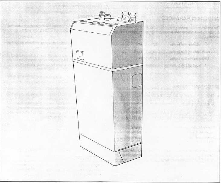
145

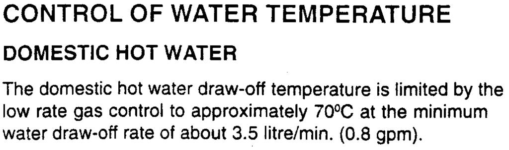

146
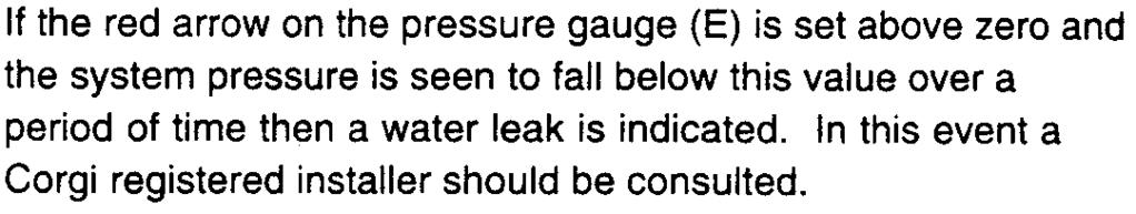
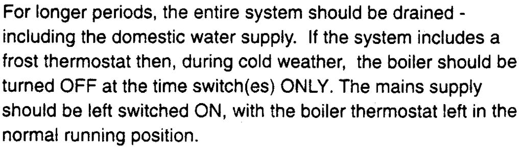
147


148
classic MANUAL INSTALLATION & SERVICING Classic FF 250P-275P Wall hung, fanned flue, gas fired boiler Installers guide to central heating boilers
 INSTALLATION & SERVICING MANUAL classic the wall hung boiler Wall hung, fanned flue, gas fired boiler Classic FF 250P-275P Installers guide to central heating boilers Classic FF - Propane Installation
installation and servicing
 installation and servicing Classic Your Ideal installation and servicing guide See reverse for Classic users guide SE15P FF, SE18P FF & SE24P FF When replacing any part on this appliance use only spare
installation and servicing
 installation and servicing Classic Your Ideal installation and servicing guide See reverse for Classic users guide SE9 FF, SE12 FF, SE15 FF, SE18 FF, SE21 FF, SE24 FF & SE30 FF When replacing any part
MANUAL INSTALLATION & SERVICING. British/Scottish Gas RD RD1. Installers guide to central heating boilers
 INSTALLATION & SERVICING MANUAL British/Scottish Gas RD1 the wall hung boiler 330-3100 RD1 Wall hung, gas fired fanned flue boiler Installers guide to central heating boilers British Gas: (Any internal
Natural Gas Models Only Minimiser G.C. Appliance No. FF FF FF
 Minimiser FF 30-80 Installation & Servicing Wall Mounted, Fanned, Super Efficient Gas Boilers Natural Gas Models Only Minimiser G.C. Appliance No. FF 30...41 387 16 FF 40...41 387 17 FF 50...41 387 18
Mexico: The Floor Standing Gas Boiler
 Mexico: The Floor Standing Gas Boiler The Ideal Mexico is a range of cast iron floor standing gas central heating boilers. Balanced, conventional or fanned flue versions are available. A complete range
2 Minimiser SE - Installation
 2 Minimiser SE - Installation Table 1 - Boiler Data GENERAL DATA Boiler Size SE 30 SE 40 SE 50 SE 60 SE 70 SE 80 Gas supply connection (in. BSP) Rc 1/2 (1/2" BSP Female) Flow connection 22mm copper (via
British Gas: 2 British Gas 100 & 125 RD2 - Installation & Servicing
 British Gas: (Any internal reference to British Gas applies equally to Scottish Gas) The British Gas RD2 is a range of cast iron floor standing gas central heating boilers. A complete range of natural
MANUAL INSTALLATION & SERVICING. British/Scottish Gas RD RD2. Installers guide to central heating boilers
 INSTALLATION & SERVICING MANUAL British/Scottish Gas RD2 the floor standing boiler 440-480 RD2 Floor standing, gas fired fanned flue boiler Installers guide to central heating boilers British Gas: (Any
GENERAL. Boiler Size 4100 FF 4125 FF. Gas Supply Connection in. BSP Rc 1/2 (1/2) Number of Boiler Sections 4 5
 Number of Boiler Sections 4 5") Table 1 - General Data GENERAL Boiler Size 4100 FF 4125 FF Gas Supply Connection in. BSP Rc 1/2 (1/2) Number of Boiler Sections 4 5 Flow and Return Connections Rc 1 (1" BSP) MAXIMUM Static Water Head m
Table 1 - General Data GENERAL Boiler Size 4100 FF 4125 FF Gas Supply Connection in. BSP Rc 1/2 (1/2) Number of Boiler Sections 4 5 Flow and Return Connections Rc 1 (1" BSP) MAXIMUM Static Water Head m
Advanced High Efficiency Boilers H12, H16, H19, H22. Wall mounted, balanced flue, fanned gas boiler. Installation & Servicing Instructions
 Advanced High Efficiency Boilers H12, H16, H19, H22 Wall mounted, balanced flue, fanned gas boiler For details of document amendments, refer to page 3 November 2005 UIN 201 029 A08 Installation & Servicing
installation and servicing
 installation and servicing icos Your Ideal installation and servicing guide See reverse for icos users guide For details of document amendments, refer to page 3 HE30, HE36 When replacing any part on this
2 Classic LX, RS - Installation
 CAUTION. To avoid the possibility of injury during the installation, servicing or cleaning of this appliance, care should be taken when handling edges of sheet steel components. 2 Classic LX, RS - Installation
Floor standing, gas fired, balanced flue boiler RS
 Floor standing, gas fired, balanced flue boiler RS 485-4125 GENERAL Table 1 - General Data Boiler Size RS 485 RS 4100 RS 4125 Gas Supply Connection in. BSP Rc 1/2 (1/2) Number of Boiler Sections 4 4 5
Advanced High Efficiency Boilers H12, H16, H19, H22. (V3 Flue System) Wall mounted, balanced flue, fanned gas boiler
 Wall mounted, balanced flue, fanned gas boiler") Advanced High Efficiency Boilers H12, H16, H19, H22 (V3 Flue System) Wall mounted, balanced flue, fanned gas boiler Packaged Boiler Contents have been checked by Operator Number... For details of document
Advanced High Efficiency Boilers H12, H16, H19, H22 (V3 Flue System) Wall mounted, balanced flue, fanned gas boiler Packaged Boiler Contents have been checked by Operator Number... For details of document
Floor standing, gas fired, balanced flue boiler RS
 Floor standing, gas fired, balanced flue boiler RS 440-470 GENERAL Table 1 - General Data Boiler Size RS 440 RS 450 RS 460 RS 470 Gas Supply Connection in. BSP Rc 1/2 (1/2) Number of Boiler Sections 2
GENERAL. 2 isar combination condensing - Installation and Servicing
 GENERAL Table 1 - General Data Gas supply 2H - G20-20mbar Gas Supply Connection 22mm copper Injector size Stereomatic 5.6mm dia. Inlet Connection Domestic Hot Water 15mm copper Outlet Connection Domestic
GENERAL Table 1 - General Data
 GENERAL Table 1 - General Data Gas supply 2H-G20-20mbar Gas Supply Connection 22mm copper Injector size Stereomatic 5.6mm dia. Flow Connection Central Heating 22mm copper Return Connection Central Heating
GENERAL. Table 1 - General Data isar HE24 HE30 HE35
 GENERAL Table 1 - General Data isar HE24 HE30 HE35 Gas supply 2H - G20-20mbar Gas Supply Connection Rc 1/2 (1/2 BSP female) Injector Size Stereomatic 5.6mm dia. Inlet Connection Domestic Hot Water 15mm
installation and servicing
 installation and servicing icos system Your Ideal installation and servicing guide For details of document amendments, refer to page 3 HE15, HE24 For users guide see reverse of book When replacing any
Alpha CD13R,18R and 24R
 Installation and Servicing Instructions Alpha CD3R,8R and 24R Wall Mounted, Fan Assisted, Room Sealed, Gas Fired, High Efficiency Condensing Regular Boiler Range For Technical help or for Service call...
installation and servicing
 installation and servicing isar Your Ideal installation and servicing guide For details of document amendments, refer to page 3 HE24,HE30,HE35 For users guide see reverse of book When replacing any part
Installation & Servicing Manual. for the Ultra range of wall mounted fan assisted balanced flue gas boilers
 405/0302-03 Installation & Servicing Manual for the Ultra range of wall mounted fan assisted balanced flue gas boilers G.C. Appliance No's. Ultra 30 41 494 78 Ultra 40 41 494 79 Ultra 50 41 494 80 Ultra
Installation and Servicing Instructions
 Installation and Servicing Instructions Alpha HE CB25/33 and HE SY25 Wall Mounted, Fan Assisted, Room Sealed, Gas Fired, High Efficiency Condensing Boiler Range For Technical help or for Service call...
Bosch Group. 24i RSF WALL MOUNTED COMBINATION BOILER FOR CENTRAL HEATING AND MAINS FED DOMESTIC HOT WATER INSTALLATION AND SERVICING INSTRUCTIONS
 Bosch Group 24i RSF WALL MOUNTED COMBINATION BOILER FOR CENTRAL HEATING AND MAINS FED DOMESTIC HOT WATER INSTALLATION AND SERVICING INSTRUCTIONS GC NUMBERS N.G. 47 311 37 L.P.G. 47 311 38 BOILER OUTPUT
kw Btu/h Metres Feet l/min. Gal/min C C
 80ic RSF WALL MOUNTED COMBINATION BOILER FOR CENTRAL HEATING AND MAINS FED DOMESTIC HOT WATER INSTALLATION AND SERVICING INSTRUCTIONS 6 720 605 553 PT 2000 11 Cat: II 2H3+ GC NUMBER NG: 47 311 43 LPG:
INSTALLATION AND SERVICING
 INSTALLATION AND SERVICING Independent C24, C0, C5 For users guide see reverse of book For details of document amendments, refer to page When replacing any part on this appliance, use only spare parts
Installation and Servicing Instructions. Alpha CD24C/32C
 Installation and Servicing Instructions Alpha CD24C/32C Range of Wall Mounted, Fan Assisted, Room Sealed, Gas Fired, High Efficiency Condensing Combination Boilers For Technical help or for Service call...
74800 Btu/h (22.0kW) HEATING INPUT MIN (60 80 C) 11.3 mbar Btu/h (25.5 kw) Btu/h (14.7kW) HEATING INPUT MAX (40 60 C)
 HEATING INPUT MIN (60 80 C) 11.3 mbar Btu/h (25.5 kw) Btu/h (14.7kW) HEATING INPUT MAX (40 60 C)") Datatable Factory settings Burner Pressure INPUT OUTPUT HEATING INPUT MAX (60 80 C) 11.3 mbar 87000 Btu/h (25.5 kw) 74800 Btu/h (22.0kW) HEATING INPUT MIN (60 80 C) 5.5 mbar 61075 Btu/h (17.9 kw) 50155
Datatable Factory settings Burner Pressure INPUT OUTPUT HEATING INPUT MAX (60 80 C) 11.3 mbar 87000 Btu/h (25.5 kw) 74800 Btu/h (22.0kW) HEATING INPUT MIN (60 80 C) 5.5 mbar 61075 Btu/h (17.9 kw) 50155
Installation and Servicing Instructions. Alpha CB50
 Installation and Servicing Instructions Alpha CB50 Wall Mounted, Fan Assisted, Room Sealed, Gas Fired Combination Boiler with Unvented Hot Water Storage For Technical help or for Service call... ALPHA
Installation and Servicing Instructions. Alpha CD50
 Installation and Servicing Instructions Alpha CD50 Wall Mounted, Fan Assisted, Room Sealed, Gas Fired, High Efficiency, Condensing Combination Boiler with Unvented Hot Water Storage For Technical help
INSTALLATION AND SERVICING
 INSTALLATION AND SERVICING LOGIC Combi 24, 30, 35 For users guide see reverse of book For details of document amendments, refer to page 3 When replacing any part on this appliance, use only spare parts
24/28. Your installation & servicing guide. installation & servicing
 NEW-Europa Users Guide.qxd 20/12/01 1:31 pm Page 2 24/28 Your installation & servicing guide installation & servicing Table 1 - General Data Gas supply Gas Supply Connection GENERAL 2H - G20-20mbar / 3P
INSTALLATION AND SERVICING
 INSTALLATION AND SERVICING Esprit eco 24, 30 For users guide see reverse of book For details of document amendments, refer to page 3 When replacing any part on this appliance, use only spare parts that
TEMPRA. Wall Mounted Fan Flue System boiler. Wall mounted fanned flue boiler INSTALLATION AND USE INSTRUCTIONS. Appr. nr. B A - CE 0063 AQ 2150
 Wall Mounted Fan Flue System boiler Appr. nr. B 94.04 A - CE 0063 AQ 2150 Phone numbers: Installer Service Engineer Serial N Wall mounted fanned flue boiler INSTALLATION AND USE INSTRUCTIONS Please read
INSTALLATION AND SERVICING
 INSTALLATION AND SERVICING LOGIC + HEAT H 12 15 18 24 30 When replacing any part on this appliance, use only spare parts that you can be assured conform to the safety and performance specification that
Installation and Servicing Instructions. Alpha CD25C/28C/35C
 Installation and Servicing Instructions Alpha CD25C/28C/35C Range of Wall Mounted, Fan Assisted, Room Sealed, Gas Fired, High Efficiency Condensing Combination Boilers For Technical help or for Service
24i RSF WALL MOUNTED COMBINATION BOILER FOR CENTRAL HEATING AND MAINS FED DOMESTIC HOT WATER INSTALLATION AND SERVICING INSTRUCTIONS
 24i RSF WALL MOUNTED COMBINATION BOILER FOR CENTRAL HEATING AND MAINS FED DOMESTIC HOT WATER INSTALLATION AND SERVICING INSTRUCTIONS GC NUMBERS N.G. 47 311 37 L.P.G. 47 311 38 BOILER OUTPUT To Domestic
Installation and Servicing Instructions. Alpha 240/280. Range of Wall Mounted, Fan Assisted, Room Sealed, Gas Fired Combination Boilers
 Installation and Servicing Instructions Alpha 240/280 Range of Wall Mounted, Fan Assisted, Room Sealed, Gas Fired Combination Boilers For Technical help or for Service call... ALPHA HELPLINE Tel: (0322)
BOILER MODEL m³/h (31.5 ft³/h)
") Technical Data BOILER MODEL 30 40 Heat Input 9.6 kw (32,600 Btu/h) 12.7 kw (43,500 Btu/h) Heat Output 80-60ºC 8.1 kw (27,700 Btu/h) 11.0 kw (37,400 Btu/h) Heat Output 60-40ºC 8.8 kw (30,000 Btu/h) 11.7
Technical Data BOILER MODEL 30 40 Heat Input 9.6 kw (32,600 Btu/h) 12.7 kw (43,500 Btu/h) Heat Output 80-60ºC 8.1 kw (27,700 Btu/h) 11.0 kw (37,400 Btu/h) Heat Output 60-40ºC 8.8 kw (30,000 Btu/h) 11.7
Alpha CombiMax 350 and 600
 Installation and Servicing Instructions Alpha CombiMax 350 and 600 Unvented Hot Water Store for use with the Alpha 240/280 Range of Gas Fired Combination Boilers For Technical help or for Service call...
GENERAL. Table 2 General Data Boiler W45 W45P W60 W60P W80 W80P 2H - G20-20mbar / 3P - G31-37mbar
 GENERAL Table 1 Performance Data Boiler W45 W45P W60 W60P W80 W80P Boiler output Max kw 43.7 58.9 78.2 (non-condensing) Btu/h 149,000 200,950 266,800 Mean 70ºC Min kw 12.6 12.6 19.5 Btu/h 43,000 43,000
CLUB HE 18 INSTALLATION AND SERVICING INSTRUCTIONS TO BE GIVEN TO THE USER SEALED SYSTEM CONDENSING BOILER. G.C. Appliance No Club HE 18
 CLUB HE 18 INSTALLATION AND SERVICING INSTRUCTIONS TO BE GIVEN TO THE USER 0087 Pin 87/BQ/44 G.C. Appliance No. 41-260-20 Club HE 18 SEALED SYSTEM CONDENSING BOILER CONTENTS CNTENTS 1 INTRODUCTION.............................
INSTALLATION AND SERVICING INSTRUCTIONS
 9/4CBi, 4/9CBi, 9/4CBi WALL MOUNTED BOILERS FOR CENTRAL HEATING AND INDIRECT SUPPLY OF DOMESTIC HOT WATER INSTALLATION AND SERVICING INSTRUCTIONS Worcester supports the Benchmark code of practice This
Ace and Ace High. Installation and Servicing Instructions To be left with user adjacent to gas meter. Wall Mounted Gas Combination Boiler
 Ace and Ace High Wall Mounted Gas Combination Boiler Installation and Servicing Instructions To be left with user adjacent to gas meter G. C. APPLIANCE No. 41 333 77 Ace G. C. APPLIANCE No. 41 333 78 Ace
INSTALLATION AND SERVICING
 INSTALLATION AND SERVICING LOGIC Code Combi ES26, ES33, ES38 For users guide see reverse of book For details of document amendments, refer to page 3 When replacing any part on this appliance, use only
Performa System 12e, 18e, 24e & 28e
 Performa System 12e, 18e, 24e & 28e Gas Fired Wall Mounted System Boilers Installation and Servicing Instructions Please leave these instructions with the user Natural Gas Potterton Performa System 12e
Bosch Group. 15SBi / 24SBi. WALL MOUNTED BOILERS FOR CENTRAL HEATING and Indirect supply of domestic hot water
 Bosch Group 15SBi / 24SBi WALL MOUNTED BOILERS FOR CENTRAL HEATING and Indirect supply of domestic hot water INSTALLATION AND SERVICING INSTRUCTIONS 24SBi This appliance is for use with Natural Gas or
ideal esprit installation and servicing HE24, HE30, HE35 For users guide see reverse of book Your Ideal installation and servicing guide
 installation and servicing ideal esprit Your Ideal installation and servicing guide For details of document amendments, refer to page 3 HE24, HE30, HE35 For users guide see reverse of book When replacing
CLUB HE 18 INSTALLATION AND SERVICING INSTRUCTIONS SEALED SYSTEM CONDENSING BOILER TO BE GIVEN TO THE USER Pin 87/BQ/44
 CLUB HE 18 INSTALLATION AND SERVICING INSTRUCTIONS TO BE GIVEN TO THE USER 0087 Pin 87/BQ/44 G.C. Appliance No. 41-260-20 (Club HE 18) SEALED SYSTEM CONDENSING BOILER CONTENTS 1 INTRODUCTION....................................
Compact. Installation & Servicing Instructions THESE INSTRUCTIONS TO BE RETAINED BY USER
 Compact Installation & Servicing Instructions THESE INSTRUCTIONS TO BE RETAINED BY USER Contents Design principles and operating sequence Page 1.1 Principle components 2 1.2 Central heating mode 2 1.3
CNTENTS. 1Introduction
 CONTENTS CNTENTS 1 INTRODUCTION............................... 0 1.1 Important Information................................. 1 1.2 General Description.................................. 1 2 TECHNICAL SPECIFICATIONS......................
HALSTEAD Ace INSTALLATION & SERVICING INSTRUCTIONS FOR THE
 INSTALLATION & SERVICING INSTRUCTIONS FOR THE HALSTEAD Ace FULLY AUTOMATIC FAN ASSISTED BALANCED FLUE COMBINATION BOILER FOR USE WITH NATURAL GAS B R I T I S H M A D E B O I L E R S G. C. APPLIANCE No.
VBX 18 & 30. Eden X Type INSTALLATION AND SERVICING INSTRUCTIONS OPEN VENT CONDENSING BOILER. SINGLE PAGES 20/9/10 09:58 Page 1
 SINGLE PAGES 20/9/10 09:58 Page 1 Eden X Type VBX 18 & 30 INSTALLATION AND SERVICING INSTRUCTIONS TO BE GIVEN TO THE USER 0086 EC 87/BP/35 G.C. Appliance No. 41-260-15 (Eden VBX 18) G.C. Appliance No.
INSTALLATION & SERVICING
 INSTALLATION & SERVICING LOGIC SYSTEM S15 S18 S24 S30 When replacing any part on this appliance, use only spare parts that you can be assured conform to the safety and performance specification that we
INSTALLATION AND SERVICING INSTRUCTIONS
 C1 WALL MOUNTED COMBINATION BOILER FOR CENTRAL HEATING AND MAINS FED DOMESTIC HOT WATER INSTALLATION AND SERVICING INSTRUCTIONS 0 I This appliance is for use with Natural Gas. GC NUMBER 47 311 53 (N.G.)
Unvented Calorifier Range. Operating and Maintenance Manual. For Models & 500
 Unvented Calorifier Range. Operating and Maintenance Manual. For Models 125 300 & 500 Telephone 08456 448802 Fax 08456 448803 Emial info@mhgheating.co.uk Web www.mhgheating.co.uk TABLE OF CONTENTS. Section
Installation and Servicing Instructions. Alpha CD25X/28X
 Installation and Servicing Instructions Alpha CD25X/28X Range of Wall Mounted, Fan Assisted, Room Sealed, Gas Fired, High Efficiency Condensing Combination Boilers For Technical help or for Service call...
INSTALLATION AND SERVICING
 INSTALLATION AND SERVICING LOGIC Combi 24, 30, 35 For users guide see reverse of book For details of document amendments, refer to page 3 When replacing any part on this appliance, use only spare parts
MULTIPOINT BF Gas Fired Balanced Flue Water Heater
 Please leave these instructions with the user MULTIPOINT BF Gas Fired Balanced Flue Water Heater User Operating, Installation and Servicing Instructions 6 720 607 090 (03.12) JS Natural Gas Main Multipoint
Bosch Group. 24CDi RSF WALL MOUNTED COMBINATION BOILER FOR CENTRAL HEATING AND MAINS FED DOMESTIC HOT WATER INSTALLATION AND SERVICING INSTRUCTIONS
 Bosch Group 24CDi RSF WALL MOUNTED COMBINATION BOILER FOR CENTRAL HEATING AND MAINS FED DOMESTIC HOT WATER INSTALLATION AND SERVICING INSTRUCTIONS GC NUMBER 47 311 30 (N.G) GC NUMBER 47 311 31 (L.P.G.)
Highflow 400 ELECTRONIC BF FLOOR STANDING COMBINATION APPLIANCE FOR CENTRAL HEATING AND MAINS FED DOMESTIC HOT WATER
 Highflow 400 ELECTRONIC BF FLOOR STANDING COMBINATION APPLIANCE FOR CENTRAL HEATING AND MAINS FED DOMESTIC HOT WATER INSTALLATION AND SERVICING INSTRUCTIONS GC NUMBER NATURAL GAS 47 311 62 BOILER OUTPUT
Finest. HALSTEAD Finest Finest Gold INSTALLATION & SERVICING INSTRUCTIONS FOR THE
 INSTALLATION & SERVICING INSTRUCTIONS Finest FOR THE HALSTEAD Finest Finest Gold FULLY AUTOMATIC FAN ASSISTED BALANCED FLUE COMBINATION BOILER FOR USE WITH NATURAL GAS OR PROPANE B R I T I S H M A D E
INSTALLATION AND SERVICING
 INSTALLATION AND SERVICING Independent C24, C30, C35 For users guide see reverse of book For details of document amendments, refer to page 3 When replacing any part on this appliance, use only spare parts
ideal esprit installation and servicing HE24, HE30, HE35 For users guide see reverse of book Your Ideal installation and servicing guide
 installation and servicing PAKAGED BOILER CONTENTS HAVE BEEN CHECKED BY OPERATOR No... ideal esprit Your Ideal installation and servicing guide For details of document amendments, refer to page 3 HE24,
Installation and Servicing Instructions. Alpha FlowSmart
 Installation and Servicing Instructions Alpha FlowSmart Hot Water System incorporating an Alpha InTec 30/40GS Condensing Combination Boiler with Integrated Flue Gas Heat Recovery Device and wall mounted
Suprima 30L - 100L. Installation & Service Instructions. About the Boiler
 Installation & Service Instructions Suprima 30L - 100L About the Boiler See inside cover for models covered by these instructions. This is a Wall Mounted Fan Assisted Balanced Flue Gas Boiler. This boiler
ATMOSPHERIC GAS BOILER INSTALLATION, OPERATING AND MAINTENANCE MANUAL
 STREBEL GENEVA CE ATMOSPHERIC GAS BOILER INSTALLATION, OPERATING AND MAINTENANCE MANUAL INDEX TABLE 1 TECHNICAL DATA SECTION 1 SECTION 2 SECTION 3 SECTION 4 SECTION 5 SECTION 6 SECTION 7 SECTION 8 SECTION
Alpha FlowSmart 25 and 50
 Installation and Servicing Instructions Alpha FlowSmart 25 and 50 Hot Water System incorporating a Flue Gas Heat Recovery Device, Primary Store and an Alpha CD Condensing Combination Boiler For Technical
INSTALLATION AND SERVICING
 INSTALLATION AND SERVICING LOGIC + Combi 24, 30, 35 For details of document amendments, refer to page 3 When replacing any part on this appliance, use only spare parts that you can be assured conform to
Compact HE. High efficiency combi boiler. Installation & Servicing Instructions THESE INSTRUCTIONS TO BE RETAINED BY USER
 Compact HE High efficiency combi boiler Installation & Servicing Instructions THESE INSTRUCTIONS TO BE RETAINED BY USER Vokèra is a licensed member of the Benchmark scheme which aims to improve the standards
Superior Mk.II. Installation, Servicing & User Instructions
 Superior Mk.II Installation, Servicing & User Instructions CONTENTS 1 TECHNICAL FEATURES AND DIMENSIONS...................................................... 1 2 GENERAL REQUIREMENTS FOR INSTALLATION..................................................
Supplied by HeatingSpares247.com
 For the installer Instructions for installation and servicing ecotec plus Wall hung open vent condensing boiler GB Contents Contents Page 1 Introduction........................... 4 1.1 Notes on the documentation............
MULTIPOINT FF Room Sealed Fan-Assisted Water Heater
 Please leave these instructions with the user MULTIPOINT FF Room Sealed Fan-Assisted Water Heater User Operating, Installation and Servicing Instructions 6 720 607 160 (04.02) JS Natural Gas Main Multipoint
INSTALLATION AND SERVICING
 INSTALLATION AND SERVICING LOGIC Combi ES ES24, ES30, ES35 For users guide see reverse of book For details of document amendments, refer to page 3 When replacing any part on this appliance, use only spare
ecotec Instructions for installation and servicing Wall hung room sealed fan assisted condensing boiler For the installer
 For the installer Instructions for installation and servicing ecotec Wall hung room sealed fan assisted condensing boiler ecotec plus 6 ecotec plus 65 ecotec plus 68 ecotec plus 64 ecotec plus 60 ecotec
Profile 40eL - 80eL. Installation & Service Instructions. About the Boiler
 Installation & Service Instructions Profile 40eL - 80eL About the Boiler See inside cover for models covered by these instructions. This is a Wall Mounted Fan Assisted Balanced Flue Gas Boiler. This boiler
Instructions for Use Installation and Servicing
 Instructions for Use Installation and Servicing To be left with the user 2000225144B.09.03 Hideaway 80B FF G.C. No. 41-047-35 Balanced Fanned Flue Boiler Hepworth Heating Ltd., Nottingham Road, Belper,
RD 628 WALL MOUNTED COMBINATION BOILERS FOR CENTRAL HEATING AND MAINS FED DOMESTIC HOT WATER INSTALLATION AND SERVICING INSTRUCTIONS
 RD 68 WALL MOUNTED COMBINATION BOILERS FOR CENTRAL HEATING AND MAINS FED DOMESTIC HOT WATER INSTALLATION AND SERVICING INSTRUCTIONS This appliance is for use with Natural Gas GC NUMBER 47 108 14 (N.G.)
Osprey 2 CFL
 Osprey 2 CFL 125-150 - 180-220 Gas Fired Floor Standing Boiler Installation and Servicing Instructions Please leave these instructions with the user Natural Gas Potterton Osprey 2 CFL 125 G.C.N o 41 590
JANUS 3 CIRCULATOR WATER HEATER INSTALLATION, COMMISSIONING & SERVICING INSTRUCTIONS G.C. No
 JANUS 3 CIRCULATOR WATER HEATER INSTALLATION, COMMISSIONING & SERVICING INSTRUCTIONS G.C. No 53 416 06 Publication No. ZZ 180/17 May 2000 These appliances are tested and certified by B G Technology for
24SiII / 28SiII WALL MOUNTED COMBINATION BOILERS FOR CENTRAL HEATING AND MAINS FED DOMESTIC HOT WATER
 SiII / 8SiII WALL MOUNTED COMBINATION BOILERS FOR CENTRAL HEATING AND MAINS FED DOMESTIC HOT WATER INSTALLATION AND SERVICING INSTRUCTIONS Worcester supports the Benchmark code of practice This appliance
INSTALLATION AND SERVICING
 INSTALLATION AND SERVICING IMAX XTRA E80 E120 E160 E200 E240 E280 For Users Guide see reverse of book When replacing any part on this appliance, use only spare parts that you can be assured conform to
Bosch Group. 15SBi / 24SBi. WALL MOUNTED BOILERS FOR CENTRAL HEATING and Indirect supply of domestic hot water
 Bosch Group SBi / SBi WALL MOUNTED BOILERS FOR CENTRAL HEATING and Indirect supply of domestic hot water INSTALLATION AND SERVICING INSTRUCTIONS SBi This appliance is for use with Natural Gas or LPG (Cat
Installation and Servicing Instructions. Alpha GasSaver GS-2
 Installation and Servicing Instructions Alpha GS- Passive Flue Gas Heat Recovery Device (PFGHRD) for use with an Alpha Condensing Combination s IMPORTANT: Read these instructions BEFORE installing the
Baxi Solo 2 RS Range. Installation and Servicing Instructions. Wall Mounted Room Sealed Gas Fired Central Heating Boilers
 Please leave these Instructions with the User. Baxi Solo 2 RS Range Wall Mounted Room Sealed Gas Fired Central Heating Boilers Installation and Servicing Instructions Natural Gas Baxi Solo 2 60 RS G.C.No.
This is a Wall Mounted Powered Flue Condensing Combination Boiler Gas Fired Central Heating Unit.
 Installation & Service Instructions Performa System HE This is a Wall Mounted Powered Flue Condensing Combination Boiler Gas Fired Central Heating Unit. The boiler meets the requirements of Statutory Instrument
Instructions for Use Installation and Servicing. To be left with the user
 4000116705-2.10.02 Instructions for Use Installation and Servicing To be left with the user 9088 XTRAMAX G.C. No. 47-047-15 Unvented Hot Water Storage Fanned Flue Combination Boiler This is a Cat II 2H3+
Instructions for Use, Installation and Servicing ecomax pro
 To be left with the user Instructions for Use, Installation and Servicing ecomax pro GB Wall hung condensing boilers for traditional open vented systems 18 E 28 E Table of Contents Page 1 List of Contents.........................
ZIP Varipoint III. Installation, Maintenance and User Instructions. Models VP303, VP503 VP803, VP953 direct unvented water heaters. Issued August 2008
 Varipoint cover qxd:varipoint cover qxd 22/8/08 11:14 Page 1 Installation, Maintenance and User Instructions ZIP Varipoint III Models VP303, VP503 VP803, VP953 direct unvented water heaters Issued August
Instructions for Use Installation and Servicing. To be left with the user
 2000225066C.03.03 Instructions for Use Installation and Servicing To be left with the user Eden Cb 11687 G.C. No. 47-260-01 High Efficiency Condensing Combination Boiler This is a Cat I 2H Appliance Reference
PLEASE LEAVE THIS MANUAL WITH THE OSO UNIT AFTER INSTALLATION INSTALLATION MANUAL
 PLEASE LEAVE THIS MANUAL WITH THE OSO UNIT AFTER INSTALLATION SOLARCYL IM/SC INSTALLATION MANUAL This manual gives detailed advice for installation and should be read carefully prior to fitting any unvented
For the installer. Instructions for installation and servicing. ecotec plus. Wall hung open vent condensing boiler
 For the installer Instructions for installation and servicing ecotec plus Wall hung open vent condensing boiler GB Contents 1 Introduction........................... 3 1.1 Notes on the documentation................
INSTALLATION AND SERVICING
 AND SERVICING HARRIER GTS 5-9 When replacing any part on this appliance, use only spare parts that you can be assured conform to the safety and performance specification that we require. Do not use reconditioned
BAXI BOSTON ALL MODELS FLOOR STANDING OPEN FLUE (OF) CENTRAL HEATING BOILERS INSTALLATION AND SERVICING INSTRUCTIONS. GAS TYPE G20 (Natural Gas)
 CENTRAL HEATING BOILERS INSTALLATION AND SERVICING INSTRUCTIONS. GAS TYPE G20 (Natural Gas)") BAXI BOSTON ALL MODELS FLOOR STANDING OPEN FLUE (OF) CENTRAL HEATING BOILERS INSTALLATION AND SERVICING INSTRUCTIONS GAS TYPE G20 (Natural Gas) BAXI BOSTON 80 OF G.C. No 41 077 65 BAXI BOSTON 70 OF G.C.
BAXI BOSTON ALL MODELS FLOOR STANDING OPEN FLUE (OF) CENTRAL HEATING BOILERS INSTALLATION AND SERVICING INSTRUCTIONS GAS TYPE G20 (Natural Gas) BAXI BOSTON 80 OF G.C. No 41 077 65 BAXI BOSTON 70 OF G.C.
Installation & Servicing Instructions
 220683B.11.96 Installation & Servicing Instructions To be left with the user 70FF 80FF GC 41 319 86 GC 41 319 60 Fanned Flue Boiler 4098 This is a Cat I 2H Appliance BS 6332 BS 5258 Reference in these
WALL MOUNTED COMBINATION BOILERS FOR CENTRAL HEATING AND MAINS FED DOMESTIC HOT WATER INSTALLATION AND SERVICING INSTRUCTIONS
 i / 8i junior WALL MOUNTED COMBINATION BOILERS FOR CENTRAL HEATING AND MAINS FED DOMESTIC HOT WATER INSTALLATION AND SERVICING INSTRUCTIONS This appliance is for use with Natural Gas or LPG (Cat II HP
30e, 40e, 50e, 60e, & 80e, fanned balanced flue gas fired boilers
 30e, 40e, 50e, 60e, & 80e, fanned balanced flue gas fired boilers THIS APPLIANCE IS FOR USE WITH NATURAL GAS (G20) ONLY Installation and Servicing Instructions LEAVE THESE INSTRUCTIONS ADJACENT TO THE
Installation & Service Instructions. Envoy System
 Envoy System 30, 40, 50, 60 & 80 Installation & Service Instructions Envoy System Wall Mounted, Fan Powered, Balanced Flue, Gas Condensing System Boiler EN0040A THE GAS SAFETY (INSTALLATION AND USE) REGULATIONS
INSTALLATION AND SERVICING
 INSTALLATION AND SERVICING February 2016 UIN 212128 A02 24, 30 For users guide see reverse of book When replacing any part on this appliance, use only spare parts that you can be assured conform to the