LABOUR DEPARTMENT HONG KONG
|
|
|
- Willa Fisher
- 5 years ago
- Views:
Transcription

1 LABOUR DEPARTMENT HONG KONG

2 UNIVERSITY OF HONG KONG LIBRARY Hong Kong Collection Gift from: Information Services Dept., Hong Kong
3 A GUIDE FOR BOILER OPERATORS BY R. COLACO LABOUR DEPARTMENT HONG KONG February 1975 PRINTED AND PUBLISHED BY THE GOVERNMENT PRINTER HONG KONG
4
5 PREFACE This text book is offered as a guide to those studying for the examination leading to the issue of a Certificate of Competency under the Boilers and Pressure Receivers Ordinance Cap. 56 of the Laws of Hong Kong. It should ensure success for the seriously minded student. It will also help the boiler operator in the day-to-day operation and maintenance of steam boilers and their auxiliary equipment. Because there are a few electrically heated boilers in use in Hong Kong, a separate chapter on electrode boilers has been included. As boiler auxiliaries are usually motor driven, a chapter on electricity has been added. The fundamentals of electricity are discussed and hints given on the care and maintenance of electric motors. Further, as fire is a serious hazard in Hong Kong, a brief chapter on fire fighting has been included. A few types of fire extinguisher commonly used in boiler room fires are described. Every effort has been made to keep the text sufficiently non-technical for the beginner, and yet contain information that will be of interest and value to the more experienced boiler operator. The generous co-operation of the Naval Architectural Draughtsmen of the Marine Department who aided in the preparation of the sketches is gratefully acknowledged. Finally, grateful thanks are expressed to Mr. CHENG Tsan-son, Translator in the Marine Department, the Inspectors of the Pressure Equipment Unit, particularly Mr. LI Wood-fan, and the Translators of the Labour Department, for their assistance in rendering the text into Chinese. R. COLACO Labour Department Hong Kong. in
6
7 CONTENTS CHAPTER I CHAPTER II CHAPTER III 'CHAPTER IV CHAPTER V -VARIOUS TYPES OF BOILERS ELEMENTS OF BOILER CONSTRUCTION Riveting Welding Boiler Stays Boiler Tubes Manholes, Mudholes And Covers Page Definition Fire Tube Boilers Water Tube Boilers 1-5 BOILER MOUNTINGS Safety Valves Water Gauges Test Cocks Steam Outlet Valves Feed Water Valves And Piping Blow-Down And Drain Pressure Gauges Fusible Plugs Scum Valves COMBUSTION Oil Fuel And Combustion Oil Burning Installations Atomizing Burners Furnace Fittings Lighting Burners Manually Automatic Controls Draught Smoke BOILER OPERATION Operating Procedure Raising Steam Oil Fuel System Oil Temperature at Burners Opening Up Steam From A Boiler To A Pipe Range Taking A Boiler Out Of Service Practical Operation And Periodic Inspection Cleaning A Fire Tube Boiler And Preparing It For Inspection Precautions To Be Observed Before Entering A Boiler Laying Up A Boiler
8 CHAPTER VI PROBLEMS OF PLANT OPERATION General Boiler Explosions Scale Formation Scale Removal Oil In Boilers Internal Corrosion External Corrosion Erosion Caustic Embrittlement Of Boiler Plates Grooving Of Boilers Bulges Priming And Foaming Tube Troubles Flame Impingement Refractory Troubles Water Hammer Page CHAPTER VII PUMPS AND OTHER AUXILIARIES Feed Water Pumps And Steam Injectors Oil Fuel Pressure Pumps Feed Water Heaters Superheaters Economizers Air Preheaters Feed Water Regulators Pressure Reducing Valves Steam Separators Steam Traps CHAPTER VIII ELECTRODE BOILERS CHAPTER IX CHAPTER X FUNDAMENTALS OF ELECTRICITY Electric Flow Units of Measurement Some Definitions Generators And Motors Why Motors Will Not Start Dangers, Remedies And Care Of Motors FIRE PRECAUTIONS, FIRE FIGHTING AND EQUIPMENT Liquid Fuel Precautions Fire Fighting Fire Fighting Equipment Diagrams
9 Definition VARIOUS TYPES OF A Steam Boiler is a closed vessel in which steam is generated under pressure greater than atmospheric. It is constructed of good quality steel and is partially filled with water when in use. Fuel is burned in the furnace and the heat thus generated is transferred to the water in the boiler, thus converting it into steam. This steam is used for a variety of purposes, viz. power generation, process, or heating service. Internally, the boiler is divided into two parts, viz. the water space, which contains water from which steam is generated, and, the steam space, which is the space above the water space. The steam space provides a storage space for the steam produced, and to a limited extent, allows the separation of steam and water. Externally, the furnace absorbs radiant heat from the burning fuel and the small diameter tubes extract further heat from the hot gases after combustion has been completed. In general, there are two main types of boiler (a) The Shell or Fire Tube type, in which the burning fuel and products of combustion are inside the furnace and tubes, with water on the outside. (b) The Water Tube type, where the water is inside drums and tubes, with burning fuel and products of combustion on the outside. Fire Tube Boilers Fire Tube boilers in common use are A. Vertical Tubular Boilers. There are various designs and makes of this type of boiler but the following are commonly encountered. (i) Vertical Cross Tube Boiler In its simplest from the boiler (Fig. 1) consists of a cylindrical shell surrounding a nearly cylindrical fire-box. A tube, called an uptake, passes from the crown of the fire-box to the crown of the shell, where it is I
10 connected to a chimney. To increase the amount of heating surface and improve circulation of the water, and also to increase the strength of the fire-box, the fire-box is fitted with one or more cross-tubes. (ii) Cochran Boiler As can be seen from Fig. 2, the crown of the fire-box and external shell of the Cochran boiler are hemispherical in shape. The hot gases of combustion pass from the fire-box through the flue-pipe into the combustion chamber, and from there through numerous tubes to the smoke-box and thence to the chimney. (iii) Vertical Dry Top Boiler This consists of a vertical cylindrical shell with flat ends as seen in Fig. 3A. The cylindrical shell surrounds a fire-box, and numerous tubes connect the top of the fire-box to the top end plate of the boiler. The hot gases pass from the fire-box through the vertical tubes to the smoke-box and chimney. Fig. 3B illustrates a vertical wet top boiler. In general, the advantages of vertical boilers are (1) The cost of construction is comparatively low. (2) A minimum area of floor space is required. (3) The tubes are the same size; one spare can replace any tube in the boiler. (4) These boilers are self-contained and require little or no brickwork. (5) These boilers are semi-portable and can be moved and set up in various locations. The disadvantages are (1) The interior is difficult of access and therefore hard to clean. (2) The water capacity is small and there is a tendency to prime. (3) Efficiency is inclined to be low and therefore they are not very economical. (4) They are prone to corrosion on the outside. (5) A comparatively high headroom is required.
11 B. Scotch Marine Boiler This type (Fig, 4) has a cylindrical shell with flat ends. The shell contains one or more corrugated furnaces which lead into combustion chambers which are more or less rectangular in shape. From the combustion chambers a large number of tubes lead the products of combustion to the front of the boiler and into the smoke-box. The advantages of Scotch boilers are (1) A minimum space is required. (2) A minimum amount of brickwork is required. (3) The headroom required is comparatively low. (4) The tubes are the same size, so one spare can replace any tube in the boiler. The disadvantages are (1) Because of the large diameter, circulation difficulties sometimes occur when starting up from cold. (2) The tubes are inclined to leak because of expansion and contraction. C. Horizontal Return Tube Boiler This type (Fig. 5) has a cylindrical shell with flat end plates which are connected together by numerous tubes. The shell is set in brickwork which forms the fire-box and combustion chamber. The hot gases of combustion pass from the fire-box to the combustion chamber and through the tubes to the front of the boiler and smoke-box. The advantages of horizontal return tube boilers are (1) The cost of construction is comparatively low. (2) The required headroom is comparatively low. (3) Circulation is simple and positive. (4) Tube replacement is fairly easy. (5) The tubes are the same Size, so one spare tube can replace any tube in the boiler. The disadvantages are (1) Needs much more brickwork than other types of fire tube boiler. (2) Has a limited capacity and pressure.
12 D. Packaged Boilers These boilers are usually Scotch marine type units. They are factory assembled, tested and adjusted. Each complete unit consists of boiler assembly, electrically-driven feed and fuel pumps, forced-draught fan, combustion equipment, also, operating and safety control equipment for either semi-automatic or fully automatic operation after initial start-up. The packaged boiler is therefore a completely self contained unit. The advantages of packaged boilers are (1) The boiler is portable and can be readily set up in various locations. (2) It is compact and therefore takes up a minimum of floor space. (3) It is easy to operate. (4) It is very efficient (5) These boilers are either semi-automatic or fully automatic. The disadvantages are (1) It cannot be operated with power off. (2) There is a danger of furnace explosion in intermittent operating. (3) Excess feed water leads to scale increase. Water Tube Boilers Water tube boilers may be classified into two divisions, viz. (i) those with straight tubes, and (ii) those with bent tubes. There are several standard types of both straight-tube or 'header' boilers and bent-tube boilers. One of each type is illustrated here. (i) The Straight-tube or Header Boiler As shown in Fig. 6, the boiler consists of inclined tubes forming a tubular heating surface, boxes or headers to which the tubes are attached, a horizontal steam and water drum, a mud-box and a furnace of suitable capacity immediately beneath the tubes. The inclined tubes are divided into vertical sections and to ensure continuous circulation of the water in one direction they are inclined from the horizontal. Baffles are placed in the path of the hot gases which deflect the gases back and forth between the tubes a number of times so that more heat may be absorbed by the boiler
13 tubes. Fig. 6 does not include a superheater but one can be fitted amongst the inclined tubes, five or six rows of tubes above the furnace, if super-heated steam is required. (ii) The Bent-tube Boiler The boiler illustrated in Fig. 7 consists of one steam drum and one water drum connected together by a main tube bank and also by a few rows of D-shaped tubes. The space between the main tube bank and the D-shaped tubes provides furnace volume. The superheater is placed within the main tube bank and baffles are fitted in the gas path so that more heat may be absorbed by the boiler tubes. On leaving the boiler the combustion gases pass through an economiser which absorbs waste heat from the gases. The advantages of water tube boilers are (1) The heating surface offered is much greater than in the fire tube type. (2) Circulation is rapid. (3) Steam generating capacity is great. (4) Access is easy and therefore cleaning and inspection are easy. (5) Pressures encountered are generally high. (6) The quantity of water is much less compared with the fire tube type. The disadvantages are (1) The initial cost is high. (2) A lot of brickwork is generally required. (3) Baffles are needed. (4) A high headroom is required.
14 CHAPTER II ELEMENTS OF BOILER CONSTRUCTION Riveting Riveting used to be extensively employed in boiler construction until a few years ago. Holes for the rivets were drilled in the plates or parts to be joined and riveting was performed either by hand or machine. Some types of rivets are shown in Fig. 8. Riveted joints most commonly used in boiler shell connections were single- and double-riveted lap joints and treble-riveted double-butt strap joints. Some riveted joints are shown in Fig. 9 9 while Figs. 10A and 10B show how concave and convex heads were jointed. Welding With the advent of electric welding riveting has been almost entirely superseded for all forms of boiler construction. In electric welding, the plate edges are machined or flame cut into a Vee and the plates to be joined are butted and welded on both sides. Molten metal from the electrode is added to the Vee, which in fusing with the plate edges forms a good efficient joint. Test pieces from the same boiler plates are welded at the same time by the same welder under similar conditions, and very severe tests are applied to these test specimens. Good welded joints are better than riveted joints. A welded joint offers less resistance to water circulation and does not allow scale to lodge; this is a disadvantage with riveted joints. Further, the amount of metal used is less and therefore the weight of the welded joint is less than a riveted one. Boiler Stays In steam boilers the flat surfaces subjected to pressure must be supported and this support is provided by stays. The principal kinds of stays in use are (a) Direct stays: round bars placed at right angles to the flat surfaces supported by them. (b) Diagonal and Gusset stays: used for supporting a flat surface by tying it to another surface inclined to the first. (c) Girder stays: placed edgewise to the flat surface to be supported.
15 Brief description of various types of stays advantages and disadvantages (a) Screw Stays (Fig. 11) are used to stay flat surfaces that are close together, for example, the flat parallel surfaces of combustion chambers in Scotch boilers. Properly spaced, these stays will give efficient service and should not interfere with the circulation of the water. (b) Through Stays (Fig. 12) are the best and most direct form of stay for supporting parallel flat surfaces that are a considerable distance apart. They do not interfere with free movement within the boiler when cleaning or carrying out repairs. (c) Diagonal Stays (Fig. 13) are used when it is not possible or desirable to carry a bar stay direct from one flat surface to another surface parallel to it. The stay may be taken in a diagonal direction and be secured to a surface at right angles to the first. Such stays take up very little room and leave more space for movement and the use of tools within the boiler. (d) Gusset Stays (Fig. 14) are diagonal stays in which a flat plate is used instead of a bar or rod. They are very rigid and liable to cause grooving of the plates along the edges of the angle bar fasteners if used where heat expansion and contraction changes are frequent. They also take up too much space and interfere with the free circulation of the water. They are most often used in Cochran boilers. (e) Girder Stays (Fig. 15) are generally used in staying the flat crowns of the combustion chambers in Scotch boilers. It consists of two plates riveted together with a space between them. It is supported at its ends on the vertical plates forming two opposite sides of the combustion chamber, and the flat crown is suspended from the girder at intervals by bolts. This is a good form of stay if properly made and fitted. Boiler Tubes Three common methods of boiler-tube fabrication are used. (1) The seamless tube is pierced hot and drawn to size. (2) The lap-welded tube consists of metal strip curved to tubular shape with the longitudinal edges over-lapping. Heat is applied and the joint is forge-welded. (3) The electric-resistance butt-welded tube is formed like the second type, but as its name implies the joint is butt-welded.
16 Manholes, Mudholes and Covers Every boiler should be provided with suitable manholes, mudholes and sightholes. These are required to enable the boiler to be properly cleaned and inspected. When a boiler is large enough, manholes not less than 12" X 16" (30.48 cm X cm) or 11" X 15" (27.94 cm X cm) should be provided, so as to allow the boiler to be entered. Fig. 16 illustrates a manhole and cover. Mudholes not less than 2J" X 3 " (6.98 cm X 8.89 cm) are provided in smaller boilers for cleaning and inspection. The covers are made oval so that they can be manipulated into the oval openings, and gaskets of asbestos rope are used on the seating surface. Yokes or 'dogs' are used to secure the cover in place.
17 Safety Valves CHAPTER III BOILER MOUNTINGS A safety valve is the most Important safety device on the boiler. Its function is to prevent excessive pressure from building up in the boiler and it is set at or below the maximum safe working pressure for the boiler it protects. The safety of the plant, the buildings, and the operators, depends largely on its efficiency. All boilers must be fitted with an approved type of safety valve of sufficient capacity to discharge all the steam that the boiler can generate without permitting the pressure to rise more than 10 per cent above the permissible working pressure. The safety valve should be connected directly to an independent steam outlet on the boiler, and no valve of any description should be placed between the safety valve and the boiler, nor on the waste steam pipe between the safety valve and the atmosphere. The main constructional requirements are that the valve lid and seat should be of non-corrosive material. The seat should be fastened to the body so that it cannot lift with the valve lid. All parts should be so constructed that failure of any part will not interfere with the full discharge capacity of the valve. Twin valves are used when the safety valve area is greater than the area of a 3J" (8.89 cm) diameter valve. Safety valves must be of the direct spring-loaded type. Weight and lever or dead-weight safety valves are not permitted because the adjustment of such valves is very easily tampered with. The safety valve spring is usually of square section for maximum clearance between the coils for if the coils come in contact the valve cannot lift. It is important that the steam opening to, and the waste steam pipe from, the safety valve should be at least as large as the safety valve connection. A lifting lever is required in order to lift the valve from its seat. It is used mainly for testing purposes. Most spring-loaded valves make use of a lip on the periphery of the actual valve lid for the purpose of giving them additional uplift once they are raised from their seats by steam pressure. This additional up-
18 lift helps to counteract the increase in spring load as the spring is compressed by the valve lifting. Fig. 17 illustrates this point. Safety valves should be placed in a vertical position and should be tested at regular intervals. The lifting lever should be pulled by hand once a day and the valve blown by steam pressure once a week. Water Gauges Every boiler must be fitted with at least one water gauge to show the water level in the boiler. In low and medium pressure boilers i.e. up to about 300 lb/in 2 (21.09 kg/cm 2 ) pressure, the water gauge consists of a round glass tube held in place by cock or valve mountings and stuffing boxes as shown in Fig. 18. The gauge glass is usually 12" (30.48 cm) long and is connected by its fittings either directly to the boiler as in the case of vertical boilers, or indirectly to the boiler through a water column. The gauge glass connections between the glass and the boiler, or the water column if this is included, 'should be at least - inch. (1.27 cm). The water column is a casting and is connected by pipes at the top and bottom to cocks or valves on the steam and water spaces of the boiler. The water column serves to eliminate excessive fluctuations of water level indication in the glass due to rapid boiler circulation, and so it acts as a steadying medium. Referring to Fig. 18, when both cocks A and B are open and clear the level of water showing in the glass will be a true indication of the level of water in the boiler. However, if the top cock A is either choked or closed, the pressure in the boiler will cause the water in the glass to rise higher than the true level of water in the boiler and a false reading will be obtained. Also, if the bottom cock B is either choked or closed, the steam will condense at the top of the glass and fill the glass, indicating a higher level than really exists in the boiler and a false reading will again be obtained. This will also happen if either of the cocks D or E, or associated piping become choked. When a water glass is broken, shut cocks A and B, remove the broken pieces and slowly open the cocks to blow out any remaining pieces. Before inserting the new glass, open the drain cock C and ensure that the glass is the exact length and that the connections are in line. Insert the glass with packing rings and tighten the stuffing box nuts by hand pressure. Then warm the glass by opening the top cock A slightly, allowing a small amount of steam to flow through the glass. 10
19 When the glass is warmed sufficiently, shut the drain cock C, open the bottom cock B slightly, and when the level of the water in the glass has become stable, open cock B fully and then open cock A fully. Water gauges should be frequently tested, particularly when taking charge after a previous shift. The safe operation of the boiler depends largely on the accuracy and condition of the gauge glass. Testing Water Gauges Referring to Fig. 18(0), the procedure to be adopted when verifying the water level in the gauge glass is as follows - First shut both steam and water cocks A and B, and open drain C, thus proving that the gauge cocks are in order. Then, with the drain still open blow through the steam cock A and then the water cock B separately to prove a clear way through both cocks and the gauge glass. Referring to Fig. 18(6), the addition of pipes and boiler-shell shut-off cocks brings in additional possibilities of faulty level indication and thorough verification of this type is a little more involved. To test a water-column water gauge glass thoroughly, the following procedure may be adopted First prove the bottom connections are in order by shutting cocks D and A, leaving E, B and drain C open; if water blows freely out of the drain C, the bottom connections are in order. Then open cocks D and A, and shut E and B; if steam blows freely out of the drain C, the top connections are in order. In the event of either end not blowing freely a cross test can be used which will show up the cock that is faulty. To cross test, close cocks D and B, leaving E, A and C open; then close cocks E and A, leaving D, B and C open. This procedure is known as a cross blow. Water Tube Boiler Water Gauges As mentioned previously, for pressures over 300 lb/in 2 (21.09 kg/cm 2 ) the round water-gauge glass is not suitable and is replaced by a built-up rectangular-section box having thick glass in front and back (see Fig. 19). It is illuminated from the rear by an ordinary electric lamp. The inner surface of the two plate glasses used are protected against any etching action of the steam by the fitting of thin sheet mica. Test Cocks On certain sizes of fire tube boiler a set of test cocks may be required in addition to the water gauge glass as a second means of determining 11
20 the water level in the boiler. Usually three test cocks are fitted, but small boilers of less' than 50 square feet (4.64 sq. m) of heating surface may have two test cocks. Test cocks may be placed on the boiler shell, in which case the lowest cock is placed level with the bottom of the glass. The others measured vertically, are placed two or three inches apart. They may also be attached to the water column, in which case one cock is fitted half way up the column and the top and bottom ones three inches above and below the middle cock. If the top test cock is opened and steam issues, a sharper sound is heard and the steam comes out in a narrow straight line. If steam and water is shown at the middle cock, the issuing mixture will be more of an umbrella shape. The bottom test cock should always show water. Test cocks should always be kept in an efficient condition. Steam Outlet Valves Every steam outlet from a boiler must be fitted with a stop valve attached directly to the boiler shell or drum, or, as near as practicable. In the case of a boiler with a superheater, the stop valve is located as near the outlet from the superheater header as is convenient and practicable. The spindles of all valves over 1- " (3.81 cm) diameter should have outside screws and the covers should be secured by bolts or stud's and nuts. All valves are arranged to shut with a clockwise motion of the hand-wheel. When two or more boilers are connected to a common header or steam manifold, the steam connection to each boiler should be provided with one stop valve and one screw-down non-return valve capable of being locked in the closed position. This is to ensure that if one of the two boilers is opened up for inspection and cleaning, steam cannot be inadvertently turned on. A stop valve capable of being locked in the closed position and a separate automatic non-return valve may be substituted for the screw-down non-return valve. Feed Water Valves and Piping Each boiler should be fitted with a feed stop valve and a nonreturn valve. Alternatively, a combined screw-down non-return valve may be fitted. 12
21 When both, a stop valve and non-return valve are fitted, the stop valve is placed nearest to the boiler. The non-return valve ensures the flow of water in one direction only, viz. into the boiler; the valve will close because of steam pressure in the boiler if the flow tends to reverse. The purpose of the stop valve is for inspecting or repairing the nonreturn valve with the boiler in service. The feed connection is made at the coolest part of the boiler and if an internal pipe is fitted, care should be taken to ensure that the cold feed water does not discharge directly on any part of the heating surface. Two separate means of supplying feed water should be installed. Slow-down and Brain Every boiler should be fitted with a suitable blow-down valve or cock placed at or as near as practicable to the lowest point of the boiler, so that all the water can be drained off. Blow-down valves are of extra-heavy construction and should be of special design to give a straight through blow off. If exposed to furnace heat, the blow-down pipe should be protected by brickwork or other heat-resisting material. It should be so arranged that the pipe may be inspected and can slide freely when the boiler is expanding and contracting. In some installations, the blow-down pipe from the boiler is led into a blow off tank which in turn discharges into the sewer. The purpose of this blow off tank is to prevent damage to the sewer from the steam and water discharged from the boiler. Pressure Gauges Every boiler must be fitted with a pressure gauge in order to measure the pressure of steam in the boiler in pounds per square inch above atmospheric pressure. The Bourdon pressure gauge (Fig. 20} was invented by a Frenchman, Eugene Bourdon. It consists of a flattened brass tube bent in the form of a circle, one end being anchored and open to the pressure to be measured, the other end being closed and free to move. The end that is free to move is attached to a toothed quadrant which operates a pinion to which a pointer is secured. This pointer moves on a dial marked off in pounds per square inch. The gauge depends for its work- 13
22 ing on the principle that a flattened, curved tube tends to straighten out when subjected to internal pressure, since there is more area exposed to pressure on the outside of the curve than on the inside. If steam entered the Bourdon tube direct it would cause it to expand or lengthen and the pointer movement would be due to a combination of pressure and heat effects. This would mean that the indicated pressure would be more than the actual pressure. For this reason the gauge is connected to the boiler through a pig-tail siphon (Fig. 21) which acts as a condenser and retains water, Boiler steam acts on this water to show correct pressure. For the same reason, the gauge should not be connected to any part of the boiler which will cause it to become heated. A I" (0.63 cm) threaded connection should be provided in the pressure gauge piping between the pig-tail siphon and the gauge to serve as a test connection. This permits attaching an inspector's gauge with the boiler under pressure. Fusible Plugs A fusible plug is another safety device for giving a warning of low water. It consists of a threaded bronze plug having a tapered hole through its centre and this hole is filled with practically pure tin with a melting temperature of 400 F to 500 F ( C to 260 C). The plug is screwed into the boiler plate at a location just above the fire line so that one end is exposed to flame or hot gases and the other is covered by water. The large end of the tapered filling is always under boiler pressure during operation. If the water level in the boiler falls below the plug, it will heat up and the fusible core will melt and fall out, allowing escaping steam to sound a warning of low water. The value of any type of fusible plug, particularly in boilers of the water tube type, is questionable. They are unreliable and little dependence should be placed on them. If used, they should be kept in good condition and renewed at least annually. When cleaning the boiler, scrape and clean the exposed surfaces of the fusible metal and the surface of the boiler surrounding the plug. In the case of oil-fired boilers low water alarms are usually fitted in preference to fusible plugs. 14
23 Seem Valves Some boilers are fitted with a surface blow off or scum valve. The scum valve is usually located slightly below the working water level of the boiler, the outlet from it being connected to the blow-down discharge pipe. It is used for getting rid of surplus water in case the water level in the boiler is too high, or for removal of scum which may be floating on the surface of the water, or for reducing the concentration of solids in the water. By judicious use of the scum valve prior to blowing down a boiler, any floating impurities can be discharged, thus preventing them from adhering to tubes and plates when blowing down. 15
24 Oil Fuel and Combustion CHAPTER IV COMBUSTION Before the Second World War coal was extensively used as a fuel. Since then however, oil has superseded coal and today it is almost universally used. The reason for this is because oil is much more consistent and has a higher heating value. The heat-producing constituents in oil are carbon, hydrogen and sulphur in the following proportions Carbon Hydrogen Sulphur per cent per cent percent When two substances having a chemical affinity for one another are brought together under favourable conditions, they combine to form a new compound. During this combination heat is generated, which if the chemical affinity is sufficiently strong, will raise the temperature of the substances to such a degree that they grow luminous. This is called combustion. In the case of fuels the heat-producing constituents combine with oxygen in the air to generate heat, with temperature ranging from F (1,010 C) to over 3,000 F (1,648 C). Carbon in the fuel if completely burned will form carbon dioxide. Hydrogen on complete combustion produces moisture, while sulphur forms sulphur dioxide. If the carbon is not completely burned due to lack of air, carbon monoxide will be formed; this means that only one third of the heat available will be generated. The various constituents of fuel on combustion will show in the furnace as follows Carbon burns with a white luminous flame. Carbon monoxide burns with a light blue flame. Hydrogen burns with a colourless flame. Sulphur tends to colour the flame yellow. 16
25 To ensure complete combustion, sufficient air must be supplied and to ensure that there is sufficient air, a controlled excess is supplied. This excess air depends on the type of draught and furnace. With a weak draught such as natural draught, about twice as much air will be required, while with mechanical draught only about one and one half times as much will be needed. Also, the amount of draught required varies with the rate of combustion. As oil is in general use in Hong Kong, only oil-burning installations will be discussed in this chapter. Oil-burning Installations A normal oil-burning installation (Fig. 22) consists essentially of a settling tank and a fuel oil unit comprising suction filter, pressure pump, discharge filter and heater. The fuel oil unit is designed to supply sufficient fuel for generating all the steam that may be required from the boiler. The hot fuel is delivered to the boiler front through a pressure line which is fitted with a circulating valve and return line to the suction side of the fuel unit. The settling tank usually has sufficient capacity for about twelve hours steaming. The tank is so named because in it any water in the oil is allowed to settle to the bottom to be drawn off at regular intervals. The tank is fitted with a filling pipe, an outlet pipe near the bottom of the tank leading to the pump suction, an air pipe and a level indicator. A drain valve is fitted near the bottom to drain off any water and sediment. From the settling tank oil is drawn by the pressure pump through a suction filter and then forced through the heater and discharge filter to the pressure line for the burners. An adjustable spring-loaded relief valve is fitted between the discharge and suction ends of the pump, so limiting the discharge to any set pressure. Oils in general use for fuel purposes in boilers are of a low grade and quite thick or viscous. In order to reduce the viscosity sufficiently to ensure efficient atomisation, oil is heated in a heater where its temperature is raised to between 150 F (65.5 C) and 240 F (115.5 C), depending on the quality of the oil. The oil heater may be heated by either steam, hot water, or electricity. 17
26 Atomising Burners Heated oil delivered to the boiler front is sprayed into the furnace by atomising burners. The main types of atomising burners are (a) Pressure Atomising Burners. In this type the pressure head of the oil fuel is converted into velocity head as it passes through small tangential holes in the atomiser tip. In addition, the holes impart a swirling motion to the oil, the discharge from the nozzle being thus broken up into a fine spray. Fig. 23 shows details of pressure atomising burner tips. (b) Steam Atomising Burners. Low pressure steam h used in this type to increase the effectiveness of fuel pressure as a means of obtaining atomisation. A typical steam atomiser burner is shown in Fig. 24. (c) Air Atomising Burners The Rotary Cup Type. Fig. 25 illustrates a horizontal rotary cup burner. In this method of atomisation the fuel oil is delivered through a tube to the back end of a cup which is rotating at high speed (4,600 to 4,700 rpm.). The oil film is spread evenly by centrifugal force over the cup surface until it reaches the rim where it meets swirl air, which is delivered there in the opposite direction of rotation. The swirl air breaks down the oil into a stream of very fine droplets. An adjustable air guide enables the shape of the flame to be varied. Furnace Fittings Furnace front fittings vary but in the main these consist of burner, air director for giving the air a conical swirling motion, a master air supply check, a secondary air supply check regulating the supply of straight unswirled air around the burner (which controls the angle and length of the flame) and a blue glass window for observation purposes when making flame adjustments. A typical arrangement is shown in Fig. 26. Lighting Burners Manually To start up any oil burning installation, close all burner valves and circulate the oil line. Then, check to see that the damper, if fitted, is wide open. The furnace should be checked to ensure that there is no accumulation of oil due to oil drippings. If the installation works on natural draught, sufficient time should be allowed for air to flow 18
27 through the furnace to carry any combustible gases up the chimney. If the installation works on mechanical draught, the furnace should be thoroughly purged by mechaninal draught before lighting the burner. The torch should then be lit and placed close to the burner tip, the oil being gradually allowed to flow until ignition occurs, and then slowly increased. When lighting the burner, stand well clear of sight holes and torch holes in furnace fronts in case of a blow back, and extinguish the torch used for lighting the burner immediately after use. If a steam atomising burner is used, the steam should be allowed to flow through the burner and clear the steam lines of condensate. Once the burner has been lit, the atomising steam should be regulated to give a good flame. To keep the consumption to a minimum steam should be gradually reduced until sparks show at the flow. This indicates that there is insufficient atomising steam and the flow should be turned on again enough to stop these sparks on the furnace floor. In starting oil installations where the furnace is cold, it is essential that plenty of excess air is furnished. This can be gradually reduced as the furnace comes up to normal working temperature. If a burner is shut down for fifteen minutes or more, the furnace should be well purged before lighting up again. When shutting off an oil burner, the oil supply to the burner should be gradually reduced before the air supply is reduced. This ensures the clearance of dangerous gases from the furnace. Automatic Controls Most new industrial boilers are fitted with automatic water level and firing controls. However, experience has shown that the incidence of damage or explosion caused by low water conditions has been relatively higher with boilers having fully automatic water level and firing controls than with those which are manually controlled. Investigation of these accidents shows the main causes to be (a) Lack of testing and maintenance of controls and alarms, leading to malfunction. (b) Isolation of control chambers. (c) Occasional inadequate standard of controls. The following paragraphs form the basis of discussion of each of the above listed causes. 19
28 Periodic Testing of Automatic Controls. The safe operation of an automatically controlled boiler depends on the correct functioning of its water level and firing controls, and such controls should be tested regularly. A suitable test procedure for externally mounted float controls fitted with sequencing blow down valves is given below. When controls are not of this type the procedure will require to be modified and expert advice of a Boiler Inspector should be sought. Daily Operating Test The following tests should be carried out at least once a day, or once a shift, by a competent boiler operator familiar with boiler controls. (a) (b) Water Level Control (i) Close the water isolating valve to the control chamber and drain the chamber. (ii) Check that the feed water is being automatically supplied to the boiler. (iii) Return valve to operating position. Firing Controls (i) With the burner operating, close the water isolating valve to the control chamber and drain the chamber. (ii) This should automatically cause the alarm to sound and the fuel and/or air supply to be cut off. (iii) Return valve to operating position. (c) Independent Overriding Control (i) With the burner operating, close the water isolating valve to the independent overriding control and drain the chamber. (ii) This should automatically cause the alarm to sound and the fuel and/or air supply to be cut off and locked out to safety. (iii) Return valve to operating position. Items (a) and (b) are often in the same chamber, and in such cases the two will be checked simultaneously. Weekly Tests At least once a week the water controls should be checked by manually interrupting the feed water supply and lowering the level of water in the boiler by evaporation until the alarm sounds and the fuel and/or air supply locks out. 20
29 After carrying out the daily and weekly tests, the boiler operator should ensure that the water level is restored to normal and all valves are in the operating position. He should not leave the boiler until he is satisfied that it is operating normally. He should remain at least a further 20 minutes. Maintenance of Controls Automatic controls should be regularly serviced and maintained by persons having the necessary competence and facilities for maintaining the particular type of control. Regular maintenance should be carried out at least once every three months. Records It is strongly recommended that a record should be kept of all periodic tests and quarterly servicing and maintenance of controls. Isolation of Control Chambers Isolation of the control chamber caused by the boiler operator closing and leaving closed either the water or steam isolating valves or both, after closing the drain, has resulted in many cases of damage and explosion from overheating of the boiler brought about by the resulting low water level. Therefore, to prevent isolation of the control chambers it is essential that the water isolating valve cannot be closed unless the drain valve is open and towards this end, valves known as 'Sequencing blow down valves', which perform this function and allow steam and water connections to be blown independently are usually fitted. This ensures that with the drain valve open, the float will be at the bottom of the chamber thereby cutting off the fuel supply to the boiler, and, it will not be possible to relight the boiler under these conditions. Standards for Automatic Controls Automatic water level controls are of two basic standards, viz. controls intended to assist the boiler operator who constantly supervises the boiler, and, controls intended to replace continuous supervision with occasional supervision. When boilers are not continuously supervised, the minimum requirements should be (a) Automatic water level controls should be so arranged as to positively control the boiler feed pumps. Alternatively, they should regulate the water supply to the boilers and effectively maintain the level of water in the boiler between certain predetermined limits. 21
30 (6) Automatic firing controls should be so arranged as to effectively control the supply of fuel to the burners, and to shut off the supply in the event of any one or more of the following conditions arising (i) Flame/pilot flame failure. The control should be of the lock-out type requiring manual resetting, (ii) Failure to ignite the fuel within a predetermined time. The control should be of the lock-out type requiring manual resetting, (iii) When a predetermined high pressure at or below the safety valve set pressure is reached. (iv) When the water level falls to a predetermined point below the operating level. This control should also cause an audible alarm to sound. (v) Failure of forced or induced draught fans, or any automatic flue damper, when these are provided. (c) Independent overriding control. This control should cut off the fuel supply to the burners and cause an audible alarm to sound when the water level in the boiler falls to a predetermined low water level. The control or its electrical circuit should be so arranged so that it has to be reset by hand before the boiler can be brought back into operation. (d) Electrical failure. All electrical equipment for water level and firing controls should be so designed that faults in the circuits cause the fuel and air supply to the boiler to be automatically sliut off. Positive means requiring manual resetting should be provided to cut off the fuel and air supplies to the boiler should there be a failure of electrical supply to water level and firing control equipment. Automatic Controls may include the following (d) (b) A Blower Damper This may be actuated by a control motor with an adjustable linkage interlocking the blower damper with the oil metering pump, proportioning the air and oil supply for high and low fire. Steam Pressure Controls These are mounted next to the column and may consist of high-low control operating limit control and line (auxiliary) control. 22
31 (c) Burner and Flame Failure Controller An electronic programming relay actuated by the steam pressure controls provides proper cycling of start, stop, ignition, and safety shut down. (d) Gas Pilot Premix type with internal spark ignition. An electrode type flame rod protects the pilot flame and permits the fuel valve to open only after the pilot flame is established. A pressure regulator and solenoid valve control the gas flow in the pilot line. (e) Low Water Control This control may be composed of two mercury tube switches operated by a metal ball float that rises and falls with changes in boiler water level. The float operates the switches through a mechanical linkage which includes a metal bellows that acts as a seal between the float chamber and the switches. Figs. 27 and 28 illustrate fundamental types of low water cut-offs. Control of Oil Burners Automatic Start-up The control system used in industrial packaged boilers are mostly electric, and a burner control panel contains most of the components and gear. Most oil burners are fully automatic requiring only a push of a button to start furnace purging, ignition, proof of ignition, and normal burner operation responsive to the pressure or temperature of the boiler. Fail-safe principles are built into most of the control functions which briefly are as follows The push of a button or a signal from a time-clock starts a motor driving a cam shaft control. Closure of the first switch starts up the forced draught fan which purges the furnace of any accumulation of combustible gas. At the same time the burner oil heater is switched on. After the fan has run for a predetermined time, the ignition system, consisting of a high tension electric spark, with or without a supplementary gas supply, is switched on. The oil is turned on provided that (d) the oil temperature is correct, monitored by a thermostat in the oil heater, and (b) there is sufficient water in the boiler, monitored by a float switch measuring boiler water level. If the flame has not ignited within a predetermined period (a few seconds only) a photocell or a lead sulphide cell scanner shuts off the fuel and returns the cam shaft to the start position. One automatic restart may be given, and if this fails, the burner locks out* requiring a manual restart. If however, as is normally the case, the scanner 23
32 registers 'flame present', the burner continues to operate under the control of boiler pressure, load, or temperature. Shortage of water in the boiler, flame failure, or failure of electric supply will cause lockout. Fig. 29 illustrates by means of a line diagram the principle of oil burner control. Some Typical Equipment Used to Control Semi-Automatic and Automatic Oil Burners With automatic oil burners it is necessary to design controls to shut off the fuel and air supply if the burner fails to ignite during starting or if the flame goes out while the burner is in operation. Without flame failure protection, the furnace will fill with an explosive mixture of fuel and air within seconds after the flame has failed. Photocells To detect flame failure, photo electric devices or photocells were developed. Photocells have the property of converting variations in light intensity into corresponding variations in an electric circuit. Thus, the light of the fire actuates the photocell and energizes a relay permitting oil to flow to the burner. Should the fire be extinguished, the flow of current in the photocell will be interrupted, the relay will be de-energised and oil flow to the burners shut off. Lead Sulphide Cells Another development for detecting flame failure is the Lead Sulphide Cell or photo scanner eye conductive cell that is sensitive to infra red radiation given off by a fire. The lead sulphide reacts to the infra red rays which envelope every flame a match, a gas flame or an exhaust. The practicability of this cell rests on an electronic circuit which receives voltage variations based on the varying resistance of the lead sulphide cell when exposed to a flame. The electronic circuit will accept and amplify only those voltage variations that correspond to the flicker frequency of the flame. The lead sulphide cell is probably one of the best types of flame failure safeguard for oil burners, especially if an orifice is used to screen out the reflected rays from the refractory (furnace brickwork). A later development uses an electronic control operated by the ultra violet rays of the flame. Fig. 30(A) is a sketch of a lead sulphide cell scanner, while Fig, 30(B) illustrates the application of the scanner. Steam Pressure Switch A steam pressure switch is shown in Fig. 31. It is actuated by a change in pressure operating on a bellows. It may be designed to open electrical contacts on a rise in pressure, or to close them under a similar condition. At predetermined pressures, it stops or starts the flow of steam. 24
33 Fuel Pressure Switch A fuel pressure switch is shown in Fig. 32. It is used to ensure sufficient pressure for proper atomisation of the fuel oil before allowing the fuel valve to open. Solenoid Oil Valve A solenoid oil valve (Fig. 33) makes use of a solenoid, which when energised will open the valve. A solenoid is an electric magnet consisting of several layers of insulated wire, and having a movable Iron plunger arranged to move in and out of the middle of the coil. When the coil is energised the plunger will be pulled in and the connecting linkage will open the valve. The pressure usually associated with solenoid valves is 85 Ib/in 2 (5.97 kg/cm 2 ). These valves may fail to operate for one or more of the following reasons (a) Valve parts or linkage fouled with dirt or foreign matter. (b) Valve parts worn out or bent. (c) Valve or linkage damaged due to rough handling. (d) Coil burned out or electrical connections broken. Draught Draught is required to supply the air which contains the oxygen necessary for the complete combustion of the fuel. It is also necessary to carry away the products of combustion, viz. the flue gases. Draught is obtained in two ways natural draught and mechanical draught. Natural Draught In natural draught, the hot gases being lighter, rise into the chimney leaving an area of negative pressure, or a weak draught, in the furnace into which cold air enters. In other words, natural draught is caused,by the difference of weight in the heated gases in the chimney and the cold air entering the furnace. To obtain a good draught the chimney temperature should be between 600 F (315.5 Q and 700 F (371.1 Q, this temperature being necessary to bring about the required difference in weight. The draught can also be improved by increasing the length of the chimney as by this means, the column of heated and therefore lighter air, is made less in weight, against the same volume of cold and heavy air. Mechanical Draught This can be produced by blower fans and the methods can be classified as follows (a) Forced Draught, which is produced by a blower fan, whereby the air is forced into the furnace. The forced draught air is 25
34 (b) usually partly heated by the waste gases before entering the furnace. Induced Draught, which is produced by an exhaust fan placed between the boiler and chimney. This exhaust fan draws the gases from the furnace and discharges them into the chimney. The advantages of forced draught over natural draught are (a) For the same power a smaller boiler would be suitable as more fuel is burned in the furnace. (b) Heated air enters the furnace instead of cold air. (c) The boiler steams better. (d) Better control of fires, as the draught is independent of weather conditions. Draught and Damper Regulation With natural draught the draught is regulated by opening or closing a damper in the chimney and controlling the air admitted to the furnace. A damper is a steel plate pivoted in the chimney and controlled by levers for opening and closing. A hand controlled damper is opened and closed according to the load and judgment of the boiler operator. When necessary, the position of the damper should be changed gradually. Automatic damper regulation is accomplished by a mechanism operated either by steam, air, or hydraulic pressure and connected by levers to the damper. Draught Gauge A simple draught gauge is illustrated in Fig, 34. The force or intensity of the draught is measured by a U-shaped glass tube containing water, one end of the tube being connected to the forced draught air trunk and the other end left open to atmosphere. The air pressure in the trunk forces the water, which is usually tinted with some colouring fluid for ease of reading, higher in the leg of the tube which is open to the atmosphere and lower in the leg of the tube open to the trunk. The difference in the two water levels is called the air pressure, and is expressed in inches of water. Purpose of a Chimney A chimney is necessary for the following reasons (a) To create a draught when no induced or forced draught fans are used. 26
35 (b) To lead the waste gases or products of combustion to a suitable height so that they will not be a nuisance to the surrounding community. When mechanical draught is used, the second reason, viz. (6), is the main one. A chimney of 75 to 100 feet (22.86 to metres) in height should create a draught of f to one inch (1.90 to 2.54 centimetres) water gauge. Smoke The products of combustion constitute smoke. Therefore, smoke consists of carbon dioxide, carbon monoxide, moisture, sulphur dioxide, nitrogen, unburnt particles of carbon, and free air. Black smoke is a definite indication of bad combustion and the colour is caused by unburnt particles of carbon. These particles being very tiny are easily carried by the moving gas stream. There will be a higher percentage than normal of carbon monoxide and the percentage of carbon dioxide will be less than normal. Causes of black smoke and methods of prevention are (a) Too little air increase forced draught pressure. (b) Carbon deposits on furnaces or combustion chambers furnaces and combustion chambers should be cleaned at regular intervals. (c) Bad atomisation causing poor penetration and bad distribution of the oil fuel spray burner nozzles should be cleaned frequently. (d) Oil fuel temperature either too low or too high correct temperature should be maintained. (e) Oil fuel pressure too low or too high correct pressure should be maintained. White Smoke If too much air is being put through the furnace the efficiency of the boiler may be seriously lowered, as the excess air is carrying away heat up the chimney. This condition usually produces white vapour. If the air supply exceeds the correct amount actually required for complete combustion, the furnace temperature is lowered as heat is lost in heating the surplus air. 27
36 In the absence of apparatus to analyse the constituents of the products of combustion, it is considered good practice to reduce the excess air from the smokeless-chimney state until a light-brown haze is obtained at the mouth of the chimney. 28
37 Operation Procedure CHAPTER V BOILER OPERATION The first duty of a boiler operator when taking over a shift is to check with the out-going operator to see if anything out of the normal occured on the previous shift. Next, he should test the water gauge glass, column, cocks or valves, and piping. This ensures that the water level in the glass is correct. The blow-down valve should also be checked to see that it is properly closed and not leaking. The pumps and auxiliary equipment should then be inspected to ensure that they are in good working order. All routine duties such as testing the water gauge glass, blowing down, soot blowing and cleaning burners should be arranged on a regular schedule. These duties could be recorded and hung up as a notice so that each operator knows what to do and when to do it. An important aspect while generating steam, is the regulation of the feed water. The water should be maintained at a definite level. Enough water should be fed into the boiler to make up for the steam that is being used. This is a fairly easy matter when feed water regulators are used or with a steady load, but it still possible with hand control of feed pumps if the operator is reasonably alert. With a straight heating load, the water might be maintained at half glass level. Where engines are involved, the level should be lower, preferably about three inches, so that carry-over or excess moisture can be minimised. In the latter case, greater care will have to be exercised, by the operator because if the pump stopped, a drop of three inches in the water level would mean the possibility of shutting off fuel to the burners. Raising Steam Inspection If the boiler is new, the operator should examine the Certificate of Fitness issued for the boiler. If it cannot be found he should notify the owner to request a Boiler Inspector to conduct an internal and external inspection of the boiler for the issue of a Certificate of Fitness. If an inspection has been made, he could request a duplicate Certificate for display in the boiler room. If the boiler is a used one, the current Certificate of Fitness should be displayed. 29
38 Preparation in the case of a new boiler When a new boiler is to be put into service for the first time, it should be thoroughly cleaned internally and any protective coating of oil on shell and tubes should be removed. Before closing up the boiler a careful examination should be made internally to ensure that all tools, waste or any other material has been removed, and that all pipe openings are clear. The lower manhole or handhole doors are re-jointed and the doors set centrally in place and tightened up. The boiler can now be filled with fresh water to half glass level, making certain beforehand that the blow-down valve is shut and that the water gauge cocks are open and drain closed. For the initial 'boiling out' of the boiler, an alkaline detergent should be used, e.g. one containing sodium carbonate, sodium phosphate or a mixture of these chemicals, together with twice their weight of anhydrous sodium sulphate to avoid intergranular cracking. Two to four pounds of such detergent per ton of water in the boiler should be adequate. The top manhole or handhole can now be jointed up. All stop valves should be eased off their seats and closed down hand-tight. To allow for escape of air during flashing up, the air cock on top of the boiler should be left open; if no air cock is fitted then the steam space test cock should be left open for this purpose. Start a fire with a small nozzle if such a nozzle is provided, and gradually bring the pressure up to 5 lb/in 2 (0.35 kg/cm 2 ). Continue boiling for about two days. Thereafter, empty the boiler and wash thoroughly with fresh water. Preparation in case of an old boiler Thoroughly clean and remove all mud and scale by scraping, chipping and washing. Where the necessary facilities exist, the use of air pressure or vacuum for removal of dust is advantageous before washing out. The shell and tubes should be inspected for signs of corrosion, cracking or leakage. Also examine the stays and internal pipes for loose connections, broken bolts or rivets, cracks, or scaled up pipes. Clean or replace the fusible plug if one is fitted. Before closing up the boiler ensure that no tools, waste or any other material has been left inside, and see that all pipe openings are clear. If dampers are fitted, operate both inlet and outlet dampers and make sure that they are free and will remain in any desired position; leave the inlet and outlet dampers open. Check to see that the blow-down valve is shut and that the water gauge cocks are open with drain closed. Check if the feed valves are in good order. All stop valves should be eased off their seats and closed down handtight 30
39 Preparation of new and old boilers Rejoint the lower manhole or handhole doors, manipulate the doors into the boiler, position centrally and tighten on dogs. Now fill the boiler with fresh water so that a quarter glass of water is showing in the water gauge and then replace the top manhole or handhole door. Open the cock to the steam pressure gauge and examine safety valves as far as is practicable to see that they are in working order. Examine the blow-down valve and piping and all other parts and fittings of the boiler before starting a fire. It is easier to rectify a fault at this stage than to have to take the boiler off range later on. In lighting up, a smaller nozzle than normally used in the working burner should be used, if one is provided. Maintain a light fire until the furnace brickwork is dried out thoroughly. If the entire brickwork is new, the drying out may require several days. If only the lining of the combustion chamber has been renewed, about 48 hours will be sufficient time for drying out. Uneven heating of the brickwork will result in cracking of the lining and brickwork, particularly in the case of new brickwork, thereby destroying its value as an insulator and support. When the boiler is beginning to show a good heat, the nuts on manhole and handhole doors should be nipped up and any new joints that have been made similarly treated. When the boiler has been uniformly heated and after steam has escaped through the air cock, the air cock should be shut and the steam pressure allowed to rise slowly to the working pressure. The water gauge should be tested to prove that it is in proper working order. The blow-down valve should be checked for leaks. It is essential that the boiler is evenly heated when raising steam. Uneven heating will cause unequal expansion resulting in distorted tubes and opening of the boiler seams (riveted joints), especially where the circulation of the water may be sluggish. After the usual week-end shut down, a light fire should be maintained for about one hour. Oil Fuel System If the system is new or has been out of service for a considerable period of time, first clean and examine the strainers, clean and examine nozzles and burners. If compressed air is available, blow out the oil 31
40 supply lines with air. Work the air registers to see that they are In good working order. Ensure that the oil valves to individual burners are shut. Remove any spilled oil about the burners, fronts, and boiler room floor, and see that there is no oil on the furnace floor. Ventilate the boiler by opening dampers. If steam is required for the oil pump and no steam is available, a hand-pump or auxiliary power pump (if such is available), is employed to charge up the oil heater and pipe line system and to circulate oil in same, between the heater and boiler front manifold. Open the drain valve on the settling tank and drain off any water and sediment that may have settled. Then open the outlet valve on the tank, the hand-pump suction valve, inlet valve to the heater, outlet valve from heater and valve to discharge and circulating valve on boiler front manifold. The burner shut-off valves require to be tightly closed. Examine oil lines and equipment for leaks. Light the centre fire by holding a hand torch near and just below the tip of the burner. Then turn on the oil and close the circulating valve to raise the oil pressure to about 50 lb/in 2 (3.51 kg/cm 2 ) or more. Stand well clear of sight holes and torch holes to avoid possible flashback. If the torch is snuffed out before the oil is lighted, shut off the oil and relight the torch. Always use the torch for lighting burners. Next, light the adjacent burners, but be sure that there is an excess of draught before lighting additional burners. Do not allow the oil to impinge excessively on the brickwork or parts of the boiler. Oil Temperature at Burners The oil temperature at the heaters is seldom more than 240 F (115.5 C). The temperature regulates the viscosity or fluidity of the oil, and the higher the specific gravity the higher the temperature required. Excessive temperature produces carbonisation of the oil in the heater tubes and furnace 'sprayers. Generally, pressure of oil regulates quantity or output through burners while temperature regulates the fluidity. Purity of oil is essential, otherwise dirt or water present may result in choking up of burner nozzles, sputtering or extinction of burners, or choked filters. For efficiency and safe working of oil fuel, the following points are of importance (a) Correct temperature of oil. 32
41 (b) Lowest pressure which will give the output required. (c) General cleanliness of heaters, filters, burners, furnace and boiler room. Opening op Steam from a Boiler to a Pipe Range In opening steam from a boiler to any pipe range, it is important to see that the drains are opened before turning on steam. The steam stop valve should afterwards be eased off the face and sufficient time allowed for the pipe to thoroughly drain itself and warm up before the valve is slowly opened up fully. As steam will condense in cold pipes, care should be taken to drain these lines as thoroughly as possible and to open any steam valve slowly and carefully. When two or more boilers comprise an installation and are connected to the same pipe range, each must be fitted with an automatic nonreturn valve directly at the boiler and a main stop valve between the non-return valve and the pipe range. When the pressure on the incoming boiler is nearing the pressure on the line, open the drain cock on the non-return valve and crack open the main stop valve until the pressure in the line between the pipe range and the non-return valve has been equalised. Then open fully the main stop valve leaving the drain on the non-return valve open. When the pressure in the in-coming boiler is about 5 lb/in 2 (0.35 kg/cm 2 ) below that of the range, open the non-return valve slowly. In order to ensure that the non-return valve functions properly, always use it automatically for putting on or taking off a boiler from range, provided the pipe range is filled with steam at working pressure. Where a superheater is installed, the normal practice is to open all header drains before lighting a burner. When steam is showing, the steam-to-superheater valves (if fitted) are opened, and after the superheater has been well blown through, the drains on the superheater inlet header are shut, leaving the outlet header drains open to create a circulation through the tubes. When the boiler has been coupled to the steam line the outlet header drains should be shut. Taking a Boiler out of Service Close the oil valve and the air register to each burner, one by one* until all burners are shut off. Then secure the main oil valve. Remove atomisers at once and drain, immersing the tips in kerosene. Keep all 33
42 openings to the furnace tightly closed to avoid quick cooling and thereby causing uneven strains in the boiler. If the boiler is a single unit the main steam stop valve can be left open. If it is one of a battery of boilers, allow the water level to fall to two inches in the glass, then close the main steam valve, feed water valve, etc., after the pressure has fallen a little due to the non-return valve closing off. If the pressure starts to rise again due to radiation from brickwork, additional water can be added to keep the pressure down. Where a superheater is installed, open the superheater outlet drains to prevent moisture from collecting in headers and tubes when the steam flow from the boiler is stopped. It is very important that all drains and vents on the superheater be kept open when there is no flow of steam through it. Practical Operation and Periodic Inspection Cleanliness Great care must be taken to see that no oil is allowed to accumulate in the air boxes, furnace bottoms, boiler room floor, etc. If a leakage from the oil system to the boiler room occurs at any time, shut off the oil 'supply to that part of the system immediately. Place oil tight trays under all fittings from which liquid fuel may escape when the fitting is opened out. Keep a sand box in a readily accessible place in the boiler room. Occasional examination of oil filters and strainers is necessary to ensure that they are in proper working order. Pressure gauges are usually fitted on each side of the filters so that the pressure difference can be frequently read for indications of clogging. Smoke observation windows and mirrors should be cleaned at least once every twenty-four hours and used constantly to see that there is no smoke. The feed water supply should be as uniform as possible and the water level in the boiler should never be allowed to get above the top of the gauge glass due to the possibility of priming if a sudden increase in steam demand occurs. If difficulty is experienced in maintaining the correct water level, the steam output of the boiler should be reduced and the cause ascertained. Low water is the most dangerous condition experienced in the operation of boilers and is generally due to inattention on the part of 34
43 the boiler operator. If the loss is gradual and noticed by the operator, the following action should be taken (a) Increase the rate of feed. (b) Check feed line for leaks or closed valves. (c) Check blow-down for leaks or open valve. (d) Start auxiliary feed system. If at any time the water level falls out of sight in the gauge glass, the boiler should be immediately taken out of service. Do not feed water into the boiler, since some parts may be very hot and application of cold water will cause sudden contraction of the material and possibly even an explosion. Ease the safety valves off their seats and let the boiler cool down. When all pressure is off, open and examine the boiler to see if any damage has been done; this means a very careful examination for signs of overheating. If any are found, the boiler inspector should be requested to make an expert examination. Boiler tubes should be kept reasonably free from soot. When a soot blower is used, drain the steam or air supply connections so that the steam or air is practically dry. Corrosion in air heaters, sometimes of a rather severe nature, is due to the deposition of sulphuric acid originating from the sulphur in the fuel, when the temperature of the gases in the heater falls below their dew point. It is therefore essential when starting up the boiler to operate the damper, by-passing the air heater until the boiler is heated throughout and there is no danger of the gases in the heater being cooled to below their dew point. A reasonably safe precaution is to by-pass the air when the temperature of the gases leaving the air heater falls to below 220 F. (104.4 C). In mechanical draught installations the operating efficiency of the fan will depend to a great extent upon the condition of the blades of the fan wheels. Due to conditions under which the fans usually operate dust will gradually accumulate on the blades and form a scale which will lower the efficiency of the blades considerably. Accumulation and wear may cause the fan wheel to be thrown out of balance. The fan wheels should be cleaned at intervals. If the fan shows any signs of being out of balance, shut it down immediately, inspect it and rebalance it. Fans are usually motor driven and all operating instructions and maintenance recommendations made by the manufacturer should be strictly observed. 35
44 Blowing down a boiler serves three objects (a) It is a rapid means of lowering the boiler water level when it accidentally rises too high, thus reducing the possibility of water hammer or slugs of water passing over with the steam. (b) It permits the removal of sediment or sludge while the boiler is in service. (c) It serves to control the concentration of dissolved solids and suspended matter in the boiler water. Except where the amount and frequency of blowing down is determined by chemical analysis, blow down freely at least once every eight hours. Blow down the boiler at a time when steam production is lowest. Where it is necessary to blow down a large amount of water, open the blow-down valve until it is about half open and leave in that position until the water is lowered about one half inch in the gauge glass; then open wide until the blowing down is completed and thereafter shut the valve. Repair leaky blow-down valves or cocks as soon as practicable. If a surface blow-off or scum valve is fitted, use it until the undesirable conditions for which it is employed are corrected. In cases where the gauge glass is not in view of the operator blowing down a boiler, another operator should be stationed where he can see the gauge glass and signal to the operator blowing down the boiler. Cleaning a Fire Tube Boiler and Preparing it for Inspection Having reduced the pressure to zero allow the boiler to cool slowly. When it is cool, open the blow-down valve and let the water drain, leaving the air vent cock or a valve on top of the boiler if no air vent cock is fitted, open, so as to allow air to enter the boiler and prevent the formation of a vacuum. Soot should then be blown and swept clear of all tubes, shell plates, heads, and seams, and every accessible external surface. The blow-down valve should be shut if any other boilers feed this line. The manhole and handhole covers, and any inspection plugs should then be removed. All loose deposits of sludge or other sediment should be washed out. The blow-down valve should be opened only when it is certain that there is no pressure in the line and no one inside the boiler. Attached scale or oil deposits should be left for the boiler inspector to see. 36
45 A boiler properly prepared for inspection should be cool, clean and dry. It is advisable to attach a red tag marked 'Man In Boiler' to the steam, blow-down, feed and fuel valves, and also to the manhole cover whenever anyone is in the boiler. Precautions to be Observed before Entering a Boiler If the blow-down enters a common line with other boilers in operation, ensure that all valves on the line to the open boiler are closed. If other boilers are operating on the same steam line, both stop valve and non-retufn valve must be closed and the drain between them open. Any other valves on lines under pressure leading to the boiler must be checked. The boiler operator on duty must be told that someone is going into the boiler. A responsible person should be stationed at the manhole door while someone is inside the boiler. Laying up a Boiler When a boiler is to be put out of service for a considerable length of time it should be entirely emptied of water and every accessible part, outside and inside, thoroughly cleaned. All soot should be removed from external surfaces and tubes, as soot is likely to absorb moisture from the air and cause corrosion. Soot should be removed from the furnace and combustion chamber. Scale and mud should be cleaned off the boiler and the boiler thoroughly washed out. Use airing-stoves to make sure that the boiler is perfectly dry inside. All steam and water connections should be tightly closed so that no water can enter the boiler. Then place trays of silica gel or calcium oxide (quicklime) inside the boiler. Place the manhole and handhole doors in position and ensure all other openings are tightly closed. The silica gel or calcim oxide absorbs the oxygen thus preventing oxidation. If the boiler is to be laid up for a period exceeding three months, the boiler should be opened after three months for inspection. Again place trays of silica gel or calcium oxide inside the boiler before closing. The external parts of the boiler coming in contact with the products of combustion should be coated with red lead to prevent external corrosion. When a boiler is to be laid off for only a few days, it is not necessary to blow it down. But if layoff is to last more than a week, the water should be brought to the boiling point with a vent open on top to discharge all gases. The water should be made alkaline by adding about 2 Ibs. (0.90 kg) of caustic soda per ton of water. 37
46 General CHAPTER VI PROBLEMS OF PLANT OPERATION Steam boiler operation places safety, efficiency and control in the hands of the boiler operator. Many automatic devices have been developed to make this control easier, safer and more efficient. However, if automatic equipment is not understood and maintained it will fail If it should fail the boiler operator must be capable of picking up manual control of many operations on a second's notice. Boiler Explosions Boiler explosions are usually the result of one of three faults (a) A defect in the boiler Defects contributing to an explosion include cracking, improper design or construction to withstand the operating pressure, and defective material used in construction. Most of these defects are a result of lack of proper inspection procedures and should be brought to light by a competent inspection. (b) A defective appliance Appliance defects most likely to cause an explosion are safety valves of defective design, or improper setting or condition of these valves. Defective installation, design, or condition of water-level-indicating equipment constitutes a similar hazard. Pressure gauge inaccuracy may lead to an explosion, as may failure of feed-water equipment, Defective blow-down equipment resulting in fouled internal surfaces of the boiler may cause explosions. Internal surfaces may be fouled from other sources to such an extent that explosions may occur. (c) Improper operation This is usually due to an incompetent or careless operator. Improper operation includes fouling of internal surfaces by neglecting water cleanliness control, or permitting low water conditions to arise. In fact, negligence or incompetence of a boiler operator may lead to any amount of trouble, from an explosion down. The results of a boiler explosion can be devastating and even a small boiler may cause tremendous damage. Small boilers, indeed, must often be considered more hazardous than large units, because of the 38
47 mistaken belief of some owners and operators that small boilers do not have a potential for destruction, and therefore, do not need competent attention. Scale Formation Scale formation on the water side of boiler heating surfaces is due, in general, to the combined effects of heat, pressure, and concentration of certain impurities in boiler feed water. The most common and most troublesome of these impurities are Calcium Carbonate and Magnesium Carbonate which tend to form soft scale, and Calcium Sulphate and Magnesium Sulphate which form a hard scale that is difficult to remove. Silica is another scale former. Scale forming water is said to be 'hard'. This hardness is either 'temporary' or 'permanent' or both. The temporary hardness may be eliminated by heating the feed water to about 212 F (100 C) in an open heater where the salts causing temporary hardness are precipitated. The permanent hardness must be controlled either by treatment in water softeners or by treatment in the boiler. The two main objections to scale on boiler heating surfaces are (a) (b) Scale is a poor conductor of heat and its presence in appreciable thickness means that less heat is absorbed by the boiler water, and the boiler efficiency is thereby reduced. Because scale is a bad conductor of heat, the heating surfaces insulated by scale from the boiler water on one side and exposed to hot gases on the other, may soon reach dangerously high temperatures. Serious damage, rupture of tubes and even boiler shells may result. Scale formation often increases with the rate of evaporation. Thus, scale deposits will often be heavier where the gas temperatures are highest. Heavy scale deposits are usually an indication of neglect, for scale can be prevented in most cases by proper treatment of the water. Where scale has formed to an appreciable thickness, it should be removed, and once the boiler is clean, steps should be taken to prevent its recurrence. 39
48 Scale Removal Scale removal is effected by one or both of the following methods (a) mechanical removal, and (i) water treatment. (a) Mechanical removal of scale is effected while the boiler is idle and empty. When soft scale is encountered it is easily washed out with a strong jet of water. Hard scale is removed with scaling tools operated by hand or power. There are two general types of mechanical tube cleaners on the market, viz. hammers and cutters. The hammers are operated by'steam or air. The hammer (Fig. 35) is inserted in the tube and strikes a hard blow first on one side and then on the other. Scale is dislodged by vibrations of the tube. Great care should be exercised in the handling of the cleaner as otherwise tubes may be deformed. Cutters used in removing scale are known as turbine tube cleaners. A cutter is operated by a small water turbine inside the casing, and may be purchased in any size to fit the various sizes of tubes. Water is led into the water turbine through a flexible hose and the cutters are thus made to revolve rapidly. By passing the cleaner back and forth through the tube, the scale is cut, and the water discharged from the turbine carries the loose scale with it. Care should be taken not to operate the turbine tube cleaner too long in one place or to force it unduly, as damage to the tube may result. The accessible parts of shells, drums, and heads are chipped with a dull chisel or scaling hammer. Care should be taken not to score the metal. (b) Water Treatment Feed water contains varying amounts of scale forming substances. It should therefore be purified before it enters the boiler. However, the methods by which this may be accomplished comprise too large a subject for detailed discussion in this chapter. Scale-forming substances composed of Carbonate compounds can to a large extent be removed from the water-by first heating the water in a feed water heater and then pumping it into the boiler. Sulphate compounds cannot be removed so easily and chemicals known as boiler compounds are commonly fed into the boiler along with the feed water while it is in operation. The compounds are composed mostly of soda ash, but as different 40

49 scale-forming substances are found in various localities it is necessary to have the water analysed. The selection of a compound for a particular feed water should be done by a skilled chemist or engineer who can determine the chemical and the amount of it needed to neutralise the scale forming properties of the impurities in the water. Alternatively, guidance could be obtained from any industrial organisation which specialises in the supply of chemicals, testing equipment, etc., for use in water treatment. In most cases, these organisations have an efficient system of technical service whereby advice and information can be provided for any particular set of conditions. Generally, the amount of the chemical needed is governed by periodic tests. The chemical is fed into the boiler along with the feed water once a day, and in time, helps in loosening any scale present and in causing the scale forming substances in the water to precipitate as mud. This can be blown out through the blowdown valve. The amount of blow down will depend on the daily tests of the water, but conscientious and regular blowing down is important. Overtreatment with chemical compounds may cause caustic embrittlement over a period of time, while on the other hand, undertreatment will allow scale to form. Thus the importance of daily tests cannot be over emphasised. Hard scale is difficult to remove by mechanical means. This work can often be materially lessened by inserting a quantity of caustic soda into the boiler and allowing the solution to boil for 24 hours on a slow fire with the boiler vented to atmosphere. At the end of this period, the boiler should be cooled and emptied and all deposits removed. This treatment often will loosen scale so that it may be washed off with a high-pressure jet of water. All water scales are soluble in acid and modern practice favours removal of scale by acid cleaning. Dilute hydrochloric, sulphuric, and other common mineral acids used with inhibitors have proved effective in removal of water scale. As strong concentrations of acid solution could prove extremely harmful to the boiler, acid cleaning should be done only under the direct supervision of a skilled consultant in^the field. Industrial organisations specialising in boiler water treatment usually provide information and service for acid cleaning'of boilers. 41
50 Oil in Boilers This is a dangerous condition. Oil is an excellent heat insulator, and its presence on heating surfaces exposed to high temperatures may cause serious overheating and damage to the boiler. Every precaution should be taken to avoid oil from entering a boiler. Not only will oil cause the boiler to foam badly, but it also has a tendency to mix with other impurities in the water, which when the boiler is not in use will settle on the metal in a spongy mass. This grease prevents the water from coming in contact with the metal. As a result the metal under operating conditions may be seriously overheated. This could lead to explosion. A common cause of the presence of oil in a boiler is the use of reciprocating steam machinery exhaust containing cylinder oil for condensate return to the boiler feed system. Also, oil fuel heating equipment may leak oil into the steam system and create this problem, if the condensate is returned to the boiler. To prevent the condition arising from these two sources, (a) a minimum amount of high-grade properly compounded cylinder oil should be used for lubrication of steam engines and pumps where the condensate is returned, and, an efficient type of oil filter should be used in the exhaust system, (b) condensate from oil fuel heating equipment may be trapped to waste or fed through an observation tank. Oil deposits should be removed from a boiler by scraping all parts within reach and then boiling out with a caustic solution. Internal Corrosion Internal corrosion is generally caused by the presence of a free acid in the feed water. The free acid may result from the splitting up of certain salts in the water, or the water supply being contaminated, or by adulterants in the cylinder oil (used in lubricating steam machinery) which find their way into the boilers, The presence of air also causes corrosion, especially in the steam space of a boiler. All wat r contains some dissolved air. When it is heated in a boiler the air will be released and the metallic surfaces attacked. Corrosion in a boiler is also due to electrolytic action. Minute stray electrolytic currents flow in the boiler-water solution between some parts of the boiler steel and a fitting of non-ferrous metal. This causes wastage of the steel, usually around non-ferrous fittings. 42
51 To prevent internal corrosion due to an acid condition of the boiler water, an analysis of the water should be made and suitable chemical treatment applied. External Corrosion Boilers in service may be exposed to external leaks of different kinds which tend to corrode the shell. The boiler operator should guard against leaky, safety valves and steam mains which drip water onto the boiler and cause external corrosion. Special attention should be given to areas where the water runs under protective coverings. Leaky manholes and handhoies are especially dangerous as they corrode the shell rapidly; such places should be kept clean and tight. Leaky tubes should be rolled, or if necessary replaced promptly, to avoid corrosion of the tube plate. Erosion Erosion is closely allied with external corrosion in its effect. But it is purely a mechanical action, a wearing away of external surfaces by sand, steam, or water, or any similar agent. Erosion by improperly adjusted soot blowers is not uncommon. Steain soot blowers should be supplied with practically dry steam and they should be well drained before use. Caustic Embrittlemeat of Boiler Plates Caustic embrittlement is a condition which sometimes develops in riveted boilers during operation and which may cause cracking leading to a dangerous condition. Laboratory workers have found that cracking due to caustic embrittlement only takes place when the metal is under stress, and at the same time exposed to high concentrations of caustic soda. In riveted boilers such conditions could occur if parts of the boiler plate are under stress due to say heavily-worked rivet holes. Small pockets are formed between the plates of the riveted joint which could collect an excessive quantity of caustic soda from the water-softening agents. Fig. 36 illustrates caustic cracking. 43
52 Extremely high concentrations of caustic soda are necessary before embrittlement can take place, and such concentrations may be found under butt straps or under laps of the plate in riveted seams. So far no cases of caustic embrittlement have been found in welded, stress-relieved or solid forged drums. Grooving in Boilers Grooving takes place in parts of the boiler material that are subjected to repeated bending action due to changes of pressure and temperature. Repetitive slight movements loosen particles of the protective film of rust on the surfaces of the steel plate as soon as they are formed, thus exposing a fresh surface for the formation of rust. Where the corrosion thus induced is confined to a particular place instead of being spread over a wide area, grooving is the result. Therefore, grooving is a form of deterioration of boiler plate by a combination of corrosion and mechanical action. Grooving is most likely to occur at the bottom of furnace necks, Fig. 37(0), and in front end plates which are flanged inwards to take the furnace, especially if the radius of the flanging is small, Fig. 37(Z>). In vertical type boilers, grooving is sometimes encountered at the junction of the firebox and shell, Fig. 38(a), in the firebox crown-plate flanging to the uptake, Fig. 38(6), and in the longitudinal lap-joints of the boiler shell, Fig. 38(c). In the case of longitudinal lap-joints of boiler shells, grooving may occur due to the plates straining to become a perfect circle; such grooves do not occur where single-butt or double-butt strap joints are used. The boiler operator can be instrumental in preventing grooving by ensuring that (a) (b) The boiler water is properly circulated during steam raising. Steam is not raised rapidly. (c) The boiler is not forced continually. (d) (e) Firing is regular. Feed-water is of good quality and is suitably treated with chemicals. 44
53 Bulges If an accumulation of scale, oil, or dirt is allowed to collect on the metal surfaces exposed to flame or hot gases, it acts as a heat insulator and keeps the water away from contact with the metal. The metal is therefore exposed to excessive heat, and may become overheated. In its overheated condition the metal will become soft and pliable. Being unable to withstand the pressure within the boiler, it is pushed out forming a bulge. Only a small distortion will take place at the first time, but this creates a pocket for more scale to lodge and increases the danger of further distortion. If the distortion is great the plate is thinned and weakened to such an extent that rupture takes place and an explosion may occur. Priming and Foaming Priming is the lifting of boiler water by the steam flow and is caused by carrying too high a water level for the demands for steam flow. The water may be lifted as a spray or in a small body, and as it enters the steam line its weight and velocity may cause severe damage to equipment. To remedy this situation the firing rate should be reduced and the surface blow-down valve opened until the water level drops to slightly below normal. The water level should be kept a couple of inches lower than normal if the demand for steam fluctuates greatly, because sudden demand for steam sometimes tends to pick up water from the surface directly below the steam stop valve. Foaming is more a chemical than a mechanical problem. High surface tension of the boiler water causes many of the steam bubbles to be encased by a water film. These film-encased bubbles rise and pass out in the steam flow. The cause of high surface tension is usually a high concentration of suspended matter in the boiler water, a high boiler water density, or the presence of oil. Priming and foaming are factors usually controllable by a competent boiler operator. Tube Troubles Tube troubles usually follow overheating due to scale, oil, or flame impingement. If the overheating is serious, a rupture may occur and the only remedy is a new tube. 45
54 Flame Impingement Flame impingement is a source of damage to boilers and refractory (brickwork). If the flame impinges directly on the boiler shell, excessive evaporation of water will result on the water surface over that point. The high temperatures may cause damage through local scale formation, or the temperature may be high enough to cause serious damage by overheating of the plate. Direct impingement of flame on tubes of water tube boilers may result in excessive evaporation, and the resultant circulation upwards in these tubes may be more rapid than the rate at which cooler water can be supplied from its lower end; thus steam pockets are formed. A steam pocket, serious overheating and failure of the tube usually result. Refractory Troubles Refractories are used mainly in water tube boilers, and in general, serve the following purposes (a) They form the envelope of the furnace or combustion chamber and assist in maintaining the high temperatures necessary for complete combustion of the fuel under all conditions. (b) They protect the furnace casing from overheating, burning, and possible escape of gases into the boiler room. (c) They ensure even distribution of heat throughout the furnace, (d) They serve to protect exposed parts of drums which otherwise could be overheated. Burner openings are usually formed by specially shaped blocks called quarl blocks. The quarls around the burners are subject to very high temperatures when the burners are in use. If the air registers are not closed tightly, or if they leak when the burners are cut out, the quarls are swept by cool air. This will bring about rapid change in temperature and cause cracking. If the quarls are not kept to their original shape and size, they will cause poor combustion, and in extreme cases, may result in serious damage to registers, furnace fronts and the remaining brick in the furnace. Dirty burners will cause dripping, improper combustion, and flame impingement on the side walls and quarls, resulting in brick failure in a very short time. These conditions should be watched for and corrected immediately, as bad brickwork may lead to serious casing damage as well as an increase in fuel consumption. 46
55 Brick and insulation behind boiler tubes, water wall tubes, floor and roof tubes, etc., should be inspected at frequent intervals. If at any time it is found cracked or otherwise defective, it should be repaired as soon as possible to reduce radiation losses and gas leaks. Water Hammer There is a definite hazard from water hammer in every steam plant. This may occur when steam Is admitted into a pipe where there is cold water of condensation. As steam enters the pipe it disturbs the surface of the water and causes the formation of waves upon it. The turbulence increases rapidly, and in a very short time one of the waves may break in such a way that its crest, in pitching forward, momentarily forms a bubble-like enclosure containing steam. By this time there is a certain amount of pressure in the pipe, and as the steam enclosed in the bubble condenses, the pressure will cause the bubble to collapse with some noise and force. This will greatly increases the agitation of the water in the immediate vicinity. Similar action will take place in other parts of the pipe and the end result is that the water in the pipe will be rolling about with great agitation. A surging wave may be big enough to block the pipe. Steam which is trapped on that side of the wave away from the steam inlet will rapidly condense creating a partial vacuum. The incoming steam behind the water wave will therefore drive it to the end of the pipe, or against an obstruction, where it will strike with great force. Pipes have often been pulled out of their fittings in this way, often with the fittings broken. In accidents of this nature, steam under pressure can be liberated in quantity with grave consequences. To summarise, the condition's favourable to water hammer are (a) Water in contact with steam. (b) Rapid condensation of steam in pipes or valve chests. (c) Agitated water surfaces in pipes. (d) Steam pressure at one part of the pipe and partial vacuum at another part. To eliminate or reduce the risk of water hammer action, open the drains provided in the steam pipe line and drain away any water as completely as possible before opening the steam valve. These drains are usually located at the lowest point in a pipe system. After the pipe line has been thoroughly drained, the steam stop valve can be cracked 47
56 open and the line warmed through. When the pipe line is well warmed usually in a few minutes the steam valve may be opened a little more, and then gradually to the full open position. Sometimes a vacuum in the steam pipe will not allow the condensed water to run out freely, as the vacuum tends to draw air into the pipe. Under such conditions the drain should be left open, and after the air has filled the vacuum, the steam stop valve should be cracked open to permit only a small amount of steam to enter the pipe to warm the air. When the air in the pipe has been warmed, a considerable amount of water should drain out if the drain is free. It is important to note that water should be expelled by the expansion of air rather than by steam pressure. Where the water in a pipe system is discharged by way of steam traps, additional hand operated drain valves should be provided so that drainage can be checked and completed. 48
57 PUMPS AND VII AUXILIARIES Feed Water Pumps and Steam Injectors Feed water pumps In general use may be divided into two classes, reciprocating and centrifugal Reciprocating Pumps One form of the reciprocating type of pump consists of two single acting pumps with two steam cylinders and two water cylinders. The steam cylinders are side by side at one end and the water cylinders are at the other end. The cylinders are connected by an open frame. The steam pistons are connected by rods to the buckets (water pistons). Stuffing boxes suitably packed at the steam and water ends keeps leakage to a minimum. In the middle of the rods are spools which actuate rocker arms for each steam valve assembly. The piston rod of one pump actuates the steam valve of the other through the rocker arm. The pistons move alternately, and since one or the other is always in motion the flow of water is practically continuous. This pump is known as a 'duplex' pump as there are two cylinders in parallel. Fig. 39 illustrates such a pump. Many reciprocating pumps have domes connected to the discharge. The reason for this is to absorb shock and give an even flow of water in the pipe. Owing to their simplicity and low first cost, reciprocating pumps are mostly found in plants using small boilers (rated at up to 17,000 Ib ( kg)/hour from and at 212 F (100 C)). Larger plants usually install centrifugal-type feed pumps in spite of the high price, because of the resulting increase in their operating efficiency. Centrifugal Pumps The principle of the centrifugal pump is that it takes the suction at the centre or fi eye* of the rotating member known as the 'impeller'. Vanes curved from the impeller eye to the periphery are curved in a volute shape, and therefore, when the impeller rotates at high speed, the velocity of the water increases rapidly. The dischargechamber construction changes this velocity to pressure. Fig. 40 shows the arrangement of a centrifugal pump. A number of impellers may be mounted on the same shaft, the discharge being fed from the periphery of each impeller to the suction, or eye, of the following impeller or 'stage'. This arrangement serves to boost the discharge pressure. Depending on the number of stages, pressure's of 1,500 lb/in 2 ( kg/cm 2 ) and above may be attained. 49
58 Steam Injectors By means of a steam injector, feed water can be forced into a boiler by the steam pressure carried in the boiler. The principle involved is that when a body of water meets a high velocity steam jet, it acquires a velocity approximately equal to that of the steam, and the energy thus generated is sufficient to overcome the boiler pressure. Steam injectors are commonly used for feeding water to small boilers. Pressure energy in the steam from the boiler is changed into kinetic energy by passing it through the coverging nozzle C (Fig. 41), from which it emerges at a high velocity. The steam in passing the opening of the pipe connection B to the feed tank, creates a vacuum in the pipe and the atmospheric pressure forces the water from the feed tank A up the pipe. The water is entrained and acted on by the steam jet. On entering the converging nozzle D, the steam condenses and gives the feed water velocity. The feed water, on entering the diverging nozzle E, gradually looses velocity, and the mass of water attains sufficient momentum to force open the feed check valve against boiler pressure. Water is thus fed to the boiler. When starting, an overflow allows for excess of steam or water or air. Oil Fuel Pressure Pumps These are usually of the rotary type and a typical gear pump is illustrated in Fig. 42. The pump consists of two small-toothed wheels gearing with one another and fitting exactly into a casing. When running, the oil is urged round between the wheels and case, filling the spaces between adjacent teeth. As there are no suction and delivery valves the pump is practically immune from breakdown. Rotary pumps are positive displacement pumps. They develop dangerously high pressures if operated against a closed discharge. They are particularly suitable for small capacities. At each revolution of the shaft a given amount of fuel oil in a steady flow is discharged. Feed Water Heaters Feed-water heaters are used to bring the feed water nearer to the temperature of the boiler water. This serves two purposes, not only does it increase the over-all boiler efficiency but it also reduces temperature stresses in.the boiler by feeding water into it at higher temperatures. 50
59 Two general types of feed-water heater are used the open and closed types. The open heater is sometimes called a 'direct-contact' heater because in this type the water and steam mix. The closed heater is sometimes called the 'indirect' heater because the water and steam are separated by tubes and the water is heated by conduction. Open Heaters The open heater makes use of exhaust steam for feed water heating and is essentially a low-pressure heater. It is always located on the suction side of the feed pump and at least five feet above the pump. In this case the hot water will flow by gravity to the pump suction when the water is pumped to the boiler. The principle of the open heater is to pass the cold condensate from the top, over a series of perforated metal trays, so that it leaves them in the form of rain. Low pressure steam enters between these trays, condensing and mixing with the water thereby heating it. There is always a certain amount of loss in return water due to leaks, blowing down, etc. A certain amount of make-up water is therefore necessary. As can be seen in Fig. 43, a make-up water pipe is fitted near the top of the heater and on this pipe is fitted a valve, controlled by a lever mechanism which is attached to a float that floats on the surface of the water in the heater. This arrangement always keeps the water in the heater at a constant predetermined level. To prevent the heater from becoming flooded an overflow is provided. Also incorporated in the heater is a filter chamber located near the bottom, the purpose of which is to extract any impurities from the water before it leaves the heater for the pump suction. As steam supply to most heaters is often the exhaust from reciprocating engines and pumps, the steam may contain a certain amount of lubricating oil, which will prove harmful if allowed to enter the boiler. Therefore, open heaters usually have some arrangement for extracting oil from exhaust steam. The shell is vented to atmosphere through a small'line, and is protected against overpressure by a relief valve. Besides raising the temperature of the feed water, the open heater performs the following important functions (a) Deposits solids causing 'temporary*'hardness.in the water. (b) Removes a considerable proportion of free oxygen by bringing the water to near boiling point and venting the gases to atmosphere. 51
60 Item (a) will help reduce scale formation in the boiler, and item (b) will help reduce corrosion and pitting in the boiler, which are accelerated by the presence of free oxygen. Closed Heaters The closed feed-water heater was originally developed to overcome the problem of oil contaminated exhaust steam. In modern steam plant, closed heaters are operated under high steam pressure and high feed water temperatures are attained by its use. It is usually located between the feed pump and the boiler. Closed heaters are designed for passing the heating steam either through the tubes, or over the tubes. In the former case the shell has to be of substantial construction to withstand boiler pressure (as the feed pumps discharge through the heater), while in the latter case the shell may be of lighter construction as it has to withstand heating steam pressure only. Closed heaters have to be provided with drains to take away the condensate of the exhaust steam. A typical closed heater is shown diagrammatically in Fig. 44. Superheaters In land boiler practice, superheaters are associated mainly with water tube boilers. They can be divided into two classes, convection and radiant. In the former the tubes are heated by the convection currents of gases passing over them, and in the latter they are heated by direct radiation from flame and hot brickwork. Steam from the boiler passes through the superheater and attains a higher temperature than would be possible otherwise. Besides having a greater volume, superheated steam because of higher temperature, contains more heat per pound than saturated steam at the same pressure. It can therefore work more efficiently. Superheating also reduces the loss of efficiency through condensation. Superheaters encountered in water tube boilers are generally of the header type. The headers, two in number, are usually of forged or fabricated steel construction, circular or rectangular in section and are connected together by U-tubes. Modern practice in the case of highly rated boilers is to weld the U-tube ends to the numerous inlet and outlet stubs fitted to the headers for that purpose during construction. It is common to fit welded-in division plates so that the steam is forced to make several passes through the superheater. The inlet and outlet branches are located on the same header. 52
61 Water tube boiler superheaters' are invariably considered as part of the boiler. They are directly connected to the steam drum without passing through any stop valve. On this account the boiler safety valves are fitted on the superheater outlet header, so that in the event of a sudden stoppage of machinery the safety valves will lift and ensure a good passage of steam through the superheater. When additional saturated safety valves are fitted (on the steam drum), they are usually loaded in excess of the superheater valves. In this case the superheater valves will lift first so as to ensure a good flow of steam through the superheater. Economisers Economises are encountered mainly in the larger water tube boiler installation. Operating and maintenance problems do not make them financially attractive for installation in fire tube boiler plant. Feed water is pumped through the economiser on its way to the boiler in order to absorb waste heat from flue gases, thereby increasing the efficiency of boiler plant. A typical economiser consists of a number of mild steel tubes on which are shrunk on gilled rings of cast-iron. The cast-iron gills provide a much extended surface for heat absorption, and at the same time protect the mild steel tubes from the acid effects of furnace gases and condensation. The flue gases pass over the tubes and the feed water pump discharges the water to the boiler through the tubes. Soot blowers are usually fitted to economizers. The casing of the independent type of economiser is located between the boiler and the chimney with the flue gases passing between the tubes. However, the trend of modern practice is to consider the economiser, when fitted, as part of the boiler and to have the outlet coupled to the boiler without any intervening fittings. Air Preheaters The air preheater is a device that uses the flue gases as a medium to heat air for combustion purposes in the boiler furnace. They are normally used is large water tube boiler plant and are installed after the economiser. Thus, further heat is recovered from the flue gases and the boiler efficiency is thereby increased. 53
62 The air preheater most frequently encountered Is the tubular type, in which thin mild steel tubes are expanded at their ends into steel tube plates. The flue gases pass on one side of the tube wall and the combustion air on the other. A lot of trouble can be experienced with corrosion and fouling of the air preheater surfaces, if steps are not taken to prevent the condensation of sulphuric acid from the flue gases. Such condensation could occur when lighting the boiler, or operating it at reduced power. To avoid trouble an air by-pass is fitted on the heater for use on such occasions. This prevents undue cooling of the heater surfaces. Normal practice is to fit soot blowers to air preheaters. Feed Water Regulators It is difficult to regulate the supply of feed water by hand, especially where the demand for steam, fluctuates. Regulators have been designed to take care of this function automatically. A common type of feed water regulator is the Copes, shown in Fig. 45. The regulator consists of two stainless-steel expansion tubes inclined at 45 and mounted in a rigid steel frame. The upper ends joint together in a yoke anchored to the frame, and are connected by a heavily lagged steam pipe to the steam space of the boiler drum. The lower ends of the tubes are pin jointed to levers, and from there lead back to the water space of the drum. The regulator is installed so that the upper halves of the expansion tubes are filled with steam and the lower halves with water. In operation, as the steam connection to the drum is heavily lagged, the steam temperature in the tubes will be the same as in the boiler. But the water temperature in the tubes will be appreciably lower as the water connection is not lagged. The levers A and B magnify the motion caused by the expansion of the tubes T, the motion of levers A and B being added and further increased by being linked together and to a further lever C. The lever C directly operates the feed water control valve, which works with very little friction. As the water level falls in the boiler drum, the level in the stainlesssteel expansion tubes falls correspondingly. More steam and less water in the tubes causes the tubes to expand, resulting in a right-hand movement of lever B and a left-hand movement of lever A. The result of these two movements is a downward movement of lever C. The down- 54
63 ward movement of lever C opens the feed control valve, and so increases the feed to the boiler as the water level falls. As the water level rises, the expansion tubes contract. This has the reverse effect and lever C is lifted, thus decreasing the feed. Pressure Reducing Valves Conditions sometimes exist in steam plants where it is found necessary to reduce the boiler pressure of the steam before it is used to supply either manufacturing processes, low-pressure feed water heaters, or other auxiliaries, as it is not economical to use high pressure steam. To achieve this, pressure reducing valves are used to supply steam at a desired constant pressure lower than that of the supply. A weight and lever type of reducing valve is illustrated in Fig. 46. The lever and weight keep the valve open while the high pressure steam enters the high pressure chamber passing through the two valve seats of the balanced valve to the outlet side at a reduced pressure. On the low pressure side, about fifteen feet away from the valve, a one-half inch pipe is taken off and connected to the underside of the diaphragm chamber. This is the control pipe which is fitted at a distance of fifteen feet in order to obtain an average pressure. To ensure that the rubber diaphragm is protected by a water seal, the point at which the control pipe enters the diaphragm chamber must be below the point at which it is taken off the low pressure line. When the pressure in the low pressure line is equalised it presses up on the diaphragm, through the spindle and closes the valve against the weight and lever. The area of the diaphragm is such as to ensure instant response of the valve to any slight fluctuations in pressure. Steam must flow in the direction indicated by the arrow cast on the body, as otherwise the valve will not function. The reducing valve must be placed in a horizontal position with the diaphragm down, so that the water of condensation which forms in the diaphragm chamber will protect the rubber diaphragm from the heat of the steam. After the reducing valve has been installed, turn on the steam, making sure that the weight on the lever is as close to the fulcrum as it will go. When the valve has warmed up, slide the weight along the lever until the desired pressure is obtained on the low pressure side. The farther out the weight is placed on the lever the greater will be the delivery pressure, and, the closer the weight to the fulcrum the lower the pressure. 55
64 In well designed installations a pressure gauge and safety valve are fitted on the low pressure side of the reducing valve. The former is required to check the operation of the regulator, the latter to protect the low-pressure equipment against excessive pressure should the regulator fail. Steam Separators Saturated steam always contains some moisture. The amount of moisture is determined by a number of factors such as the design of a boiler, the manner in which it is operated, and faulty or poor insulation. As the presence of moisture in steam interferes with the lubrication of engines, scores valves and cylinders, absorbs heat from the steam by re-evaporating during the expansion of the steam, and if in sufficient quantity can cause damage to the engine, efforts are made to separate moisture from steam. This separation is achieved either by superheating the steam sufficiently to evaporate all moisture, or, by the use of a separator which reduces the moisture content to acceptable limits. The normal design of separator depends upon the effectiveness of an abrupt change of direction of the flow of steam and water to separate substances of different densities. Fig. 47 illustrates one form of steam separator, in which, the steam is subjected to a sudden change of direction of travel. Steam being lighter than the moisture contained in it will make the change, but the moisture being heavier has more momentum and will continue travelling in the original direction until it strikes against the baffle. Water droplets are formed and fall to the bottom of the separator and are drained to a steam trap. Any particles of grease, oil or dirt are likewise thrown off by the steam. Steam Traps Float Traps The principle of operation of both float type and bucket type traps are practically the same. In the float trap (Fig. 48) the hollow ball floats on the return condensate water which flows by gravity from the steam line drains to the trap. The float, which actuates a valve on the trap outlet through a lever mechanism, rises when the level of water in the trap rises and this action opens the outlet valve allowing the water to be discharged. When the level of water drops, the float is lowered and closes the valve. A vent is fitted on top of the trap to allow for the escape of any air which may collect. 56
65 Bucket Traps Fig. 49 illustrates a bucket trap. The water of condensation enters at A and fills the spaces S between the bucket B and the walls of the trap. This causes the bucket to float and close valve V. The water rises in the chamber until it overflows the edges of the bucket causing it to sink and open valve V. Steam pressure acting on the surface of the water forces it up through ring R and through discharge opening D. When the bucket is emptied it again floats closing valve V. The cycle is then repeated. A good boiler operator always ensures that trap outlet valves are in good condition as otherwise steam would escape from the trap and go to waste, resulting in inefficiency. 57
66 CHAPTER VIII ELECTRODE BOILERS There are several distinct types of electrically heated steam generators. In the floating-electrode type, water boils at the surface and the level of the electrode falls as the water evaporates. In another type, control is exercised by partial immersion of the electrodes. In both cases, water is heated directly by passing alternating current through it. Boilers for medium-voltage supplies are made with loadings from 10 kw to 3,000 kw, and full pressure, up to 300 lb/in 2 (21.09 kg/cm 2 ) is available in three to five minutes after switching on. Very small generators may have working pressures as high as 1,000 lb/in 2 (70.32 kg/cm 2 ), such pressures usually being required for pressure testing of equipment. A typical electrode boiler (Fig. 50) comprises a steel shell containing current carrying electrodes. Usually three in number, the electrodes are insulated from each other and from the shell. When starting, water is pumped into the boiler and as soon as it reaches the electrode tips, current flows between them. The principle applied here is that the passage of current through any resistance causes a rise in temperature within the material of the resistance. In the boiler, the passage of current through the water causes a rise in temperature in the water. Heat is generated within the water and is not transmitted from an external source at a higher temperature. As the water level rises around the electrodes, more current flows until the amount of steam generated exactly matches the demand. The heat generated is equivalent to the electrical energy expended, and the boiler operates at 100 per cent efficiency, less the slight loss due to radiation. When closed down the boiler shell is empty and no current flows. The electrode boiler is therefore absolutely safe when dry. Electrode boilers are controlled in two ways (a) by pressure, and (b) by load. A load selector switch enables the electrical load of the boiler to be selected in 20 per cent steps up to full load, and in no case does the boiler take a greater proportion of the load than selected. Operation is. completely automatic. Since the controls regulate the load taken by the boiler to meet the steam demand, a constant working pressure is maintained. 58
67 Electrode boilers being small and compact can be installed in places which would be useless for any other purpose e.g. under stairways, on roofs of buildings, often enabling the boiler to be located at the equipment using the steam. Electrode boilers can be used only on alternating current supplies. For with direct current the two elements which constitute water, viz. hydrogen and oxygen, would be liberated due to electrolysis. With alternating current at frequencies of 10 cycles per second and above, no electrolysis taken place. The majority of electrode boilers run on three-phase systems. As the cost of electricity is generally higher than the cost of oil fuel (even with special rates for supply), the operating cost of an electrode boiler is usually high. However, it does not require a chimney and is not susceptible to variations in draught. It may be installed where most convenient, and is in fact portable. 59
68 CHAPTER IX FUNDAMENTALS OF ELECTRICITY Electric Flow Electricity when in motion is a form of energy. Its precise nature is not yet clearly understood, its presence is rarely obvious, and its results are often sudden and tremendous. It is convenient to think of electricity as a fluid flowing around a path, without loss. The electron theory supposes that atoms which constitute all known physical matter are composed of Electrons having a negative charge, and Protons having a positive charge. The electrons, which are capable of movement, normally circulate the positive protons called the Nucleus of the atom. Atoms of different substances differ only in the number and grouping of their electrons. Under the action of a force and with movement restricted to a definite path, such as along a wire, electrons will flow in a stream. Electricity is thus easily transmitted from a central supply and distributed to any number of places where it is to be used. The force which sets the electrons in motion outside the confines of their atoms is called the Electro Motive Force. Therefore, Electro Motive Force (E.M.F.) is that force or pressure which causes a flow of electricity in a circuit. A difference of E.M.F. is called Potential Difference (P.D.) and may be set up by chemical action, by heat, or by mechanical means. It is usual to regard one side of this difference as positive and the other as negative, and to call the positive the high pressure and the negative the low pressure. The unit of electro motive force is the Volt. As long as a potential difference exists in a circuit a Current will flow through it. The current is assumed to flow from the positive to the negative. Units of Measurement A Volt is an electrical unit of pressure, and is the force required to send one ampere of current through a resistance of one ohm. An Ampere is an electrical unit of current, and is the current produced by an E.M.F. of one volt in a circuit with a resistance of one ohm. 60
69 An Ohm. Resistance is offered by all substances to the flow of current through them and this resistance is measured in ohms. An ohm is therefore an electrical unit of resistance, and is the resistance offered by a circuit to the passage of one ampere of current under a potential difference of one volt. A Watt is the electrical unit of power, and is the power expanded in a circuit when a current of one ampere flows between two points at a potential difference of one volt. A Kilowatt. The watt is too small a unit for practical purposes, so a larger unit called a kilowatt and equal to one thousand watts, is generally used. A Watt Hour is the electrical unit of energy and is the energy supplied by one watt for one hour. A Kilowatt Hour is the large, practical unit of electrical energy and represents the energy supplied by one kilowatt for one hour. Some Definitions An Electrical Circuit is a system of electric conductors providing a continuous path for the purpose of carrying current. An example is current flowing from its source through a system of motors or Hghts, back to its source by the necessary wiring. A Circuit Breaker is a special type of switch designed for opening automatically a current carrying circuit when under excess current conditions, such as overloads or short circuit currents, thus safe-guarding the circuit. An ordinary switch, unlike a circuit breaker, is not designed for the interruption of short circuit currents. An Electric Switch is a device for closing and/or opening a circuit under the conditions of load for which it is rated. Switches are made in a variety of forms, from the simple lighting 'tumbler' or link switch to the larger knife switches. It can also be a single, double, triple or four pole type or a single or double throw switch. A Fuse is a device for the purpose of protecting a circuit against damage and acts as an automatic circuit-breaker. It consists in most cases of a strip of lead or tin, placed in line with the main wire which is cut to allow of the fuse being fitted in its place. The ends of the fuse are connected to small terminals or screws. 61

70 Fuses are arranged so that should an excess current, caused by some defect or breakdown, attempt to pass, the strip of tin or lead would melt and break the circuit automatically, thus preventing further damage by burning out the rest of the circuit beyond where the fuse is placed. Fuses are fitted on switchboards, distribution boxes, and for general safety at various other places on lamp circuits. When renewing fuses, the main switch should always be opened, if possible, and a regular fuse cartridge used for fuses carrying high currents or voltages. Fuses should not be handled unless it is ascertained that the line is dead, and, the person carrying out the work should always stand on a rubber mat or a dry piece of wood, if one side of the switch is still alive. A Relay is a device for opening or closing an auxiliary circuit, or for releasing circuit breakers or switches. Other types actuate for time control, for counting, sorting, or measuring. These release devices may be of the thermal, magnetic, or induction types. Overload relays operate when an overload occurs, and, no-voltage relays operate on low or no voltage. These two types are generally used with starting equipment. D.C. means Direct Current and refers to an electric current flowing through a conductor in one direction only, i.e. the axial drift of the electrons is in one direction only. A.C. means Alternating Current and refers to an electric current flowing through a conductor the direction of which is reversed at regular intervals, i.e. the axial motion of the electrons is a backward and forward motion. A generator in which the current reverses in strength and direction 50 times per second, is called a 50 cycle generator. An Electric Generator is a machine that converts mechanical energy into electrical energy. There are D.C. generators and A.C. generators or alternators. An Electric Motor is a machine that converts electrical energy into mechanical energy. There are D.C. motors and A.C. motors. A Rheostat, To prevent over-current damage to motors when starting, and, in some cases to vary the speed of motors, rheostats are used. A rheostat is a variable resistance which generally consists of a series of brass contacts arranged in various forms and which are connected to one another by a resistance coil. A contact arm slides over the brass contacts, cutting out each resistance in turn. 62
71 An Electrical Conductor is a substance which permits the flow of electricity through it without offering much resistance. The best conductors of electricity are metals, silver being the best of all but too expensive for common use. Copper and aluminium are next best and are in general use. An Electrical Insulator is a substance which offers considerable opposition to the passage of electricity. Such substances are called nonconductors or dielectrics, the most common being air, indiarubber, mica, glass, porcelain, plastic materials, and textile fabrics. Generators and Motors An electric current is generated when a coil of wire is passed through or rotated in the magnetic field of a magnet, the magnetic field being the invisible lines of force given off by the magnet. Generators make use of this principle, and consist of a number of conductors continually cutting across magnetic fields. In direct current generators, the field magnets are made to produce a magnetic field by passing either all or part of the total current generated through coils of wire wound on the magnet. In alternating current generators, the magnets are energized from an external source of direct current; this is because alternating current is fluctuating and therefore cannot be used for such a purpose. This external source is usually a 'small D.C. machine called an exiter, and the D.C exiting current is led into the rotor of the A.C. generator by means of brushes and slip rings, generally two in number. In D.C. generators and motors, the field (field poles of iron laminations and coils) is always stationary and the armature revolves within the influence of the field. In A.C. generators and motors, the field poles are generally the revolving member, the armature being stationary. The conductors of the armature are wound in the slots of the iron laminations of the frame. The revolving part of the A.C. generator is called the rotor and the stationary part the stator. All generators generate alternating current, but in the D.C. machine a copper commutator and carbon brushes are povided to convert the A.C. current into D.C. current before it leaves the machine. Why Motors Will Not Start Some of the reasons why a motor will not start are 63
72 Switch not closed Low voltage Overload Blown fuse or fuses Broken wire Rheostat burned out (D.C.) Contacts burned out Poor brush contact (D.C.) Windings burned out Short circuit in windings Relays out of contact Damp insulation Defective insulation Excessive grease or oil Excessive dust Excessive bearing friction Worn out bearings Journals too tight Wrong frequency Uneven air gap Improper alignment of motor with the machine it is driving Dangers, Remedies and Care of Motors Danger to Personnel The physical danger from an electric motor would be an electric shock or even electrocution resulting in death in the case of an earth or short circuit. These conditions could arise through carelessness, defective or worn out insulation, or excessively damp conditions. Faults in Motors Motors could be damaged due to sudden surges of current in the line, moisture, or excessive temperature causing damage to the insulation or materially reducing its normal life. Excessive temperature is usually attributed to overloading, blocking up of the ventilation passages with dirt and fluff, or accumulation of foreign matter on the windings and core acting as insulation and thereby preventing dissipation of heat. A water hose played at or near a motor is not only dangerous to the motor, but also dangerous to the man with the hose since water is a good conductor of electricity. Overflowing of liquid tanks, filters, or dying tubs should be guarded against. Danger can also arise from water leakage at the packing glands of motor driven pumps. Excessive vibration should not be allowed. Oil or grease should be prevented from entering the motor and should be used only in proper amount in the bearings. A motor will normally last for twenty years if serviced correctly. It should then be rewound if any doubt exists regarding the quality of the insulation. 64
73 Care and Maintenance Lubrication and care of insulation are the main factors governing the life and efficiency of a motor and both are often neglected. Lubrication, of course, would apply to the bearings, whether sleeve, ball, or roller, and modern types of bearings are very efficient. However, too much oil added to the sleeve type bearing, or too much grease applied to ball or roller bearings, may cause the"surplus to be carried into the motor where it traps dirt and aids in breaking down the insulation. Often, grease fittings are inserted into the pipe thread openings on the ball bearing housings and a shot or two of grease Is added whenever someone feels like adding it. Some housings have been so packed with grease in this way that bearing friction has increased sufficiently to affect the running of the motor. In modern design, bearings are usually dust proof, and in the sleeve or journal type, oil levels should be checked daily and a little oil added weekly if necessary. If an oil gauge is used in pedestal bearings, check oil level by the line in the gauge glass. It is best to add oil when the motor is stopped. If oil is found to be leaking or creeping along the shaft, check oil level and ascertain cause of leakage. Bearing oil should be changed every three months if the motor is in a dirty location, and in any case should be changed every six months, the oil wells being flushed and cleaned before refilling. Ball or roller bearings should be checked every week for vibration while the motor is running and the temperature checked daily by feeling with the hand. If the motor is running continuously and on hard service, grease should be flushed out with kerosene or trichloroethylene if in a horizontal motor, but in the vertical type the bearings should be stripped and re-assembled after cleaning. In most motors, a pipe plug is placed top and bottom of the bearing housing. After the bearing and housing are flushed out, leave top and bottom plugs out and pack the housing with a grease gun. Allow surplus grease to work out through the pipe opening and then seal with pipe plugs. In the case of special locations where extreme heat is present, the type of grease is changed to suit the condition. Sleeve bearings are generally used for horizontal motors and for D.C. machines while ball or roller bearings are used for tilted, vertical or horizontal positions. Insulation is best cared for by keeping the motor clean and free from dust, damp, and oil. Under normal operating conditions motors should be cleaned once a week and this can be done with dry, low pressure air. 65
74 At least once a year the motor should be thoroughly cleaned and overhauled. The condition of the insulation should also be tested by a resistance testing instrument such as a megohmmeter. During the yearly cleaning of the motor, the dust could be blown off using dry, low pressure compressed air (about 25 lb/in 2 or 1.75 kg/ cm 2 ), and the dirt and grease removed by brush or cloth, using a cleaning fluid such as trichloroethylene. When clean, the motor should be dried thoroughly, preferably in an electric oven, and then a coat of insulating varnish applied to the windings by brush or spray gun. The stator frame should be dried using electric heaters. When re-as'sembled, the motor clearance or air gap should be checked. 66
75 CHAPTER X FIRE PRECAUTIONS, FIGHTING AND EQUIPMENT Liquid Fuels Liquid fuels all evaporate at rates varying with the temperature, the more volatile fuels being those which give off vapour more readily at lower temperatures. With appropriate quantities of air, these vapours form mixtures which will flash or explode if ignited. If ignition takes place inside a compartment there will be an explosion with destructive results. The destructive ability of vapour mixtures exceeds that of many solid explosives; a cupfull of gasoline has the potential explosive power of 5 Ibs (2.26 kg) of dynamite. Precautions Precautions relating to the storage of liquid fuel generally aim at achieving (a) (b) The elimination of either liquid or vapour accumulations outside the oil fuel tank or pipe system in use. The exclusion of all sources of ignition from the neighbourhood of any position where vapour-air mixture may have developed. Air vent pipes to oil fuel tanks should be fitted with flame arresters consisting of double wire gauze of fine mesh. They must be kept clean, especially from paint, to allow them to fulfil their purpose. In the boiler room no oil should be allowed to accumulate in the air boxes, furnace bottoms, or boiler room floor. If leakage from the oil fuel system to the boiler room occurs at any time, the oil supply to that part of the system should be shut off immediately. Oil-tight trays should be placed under all fittings from which liquid fuel may spill when the fitting is opened. Savealls should be frequently examined for the presence of oil A box filled with sand should be kept in a readily accessible place in the boiler room. Oily waste can set light to itself without any external application of heat such as from a flame or spark; this is called spontaneous ignition. Therefore, until it can be disposed off or burnt, oily waste should be kept in a metal receptacle partially filled with water to prevent spontaneous ignition. 67
76 In general, the best safeguard against fire is a proper attitude towards cleanliness, the disposal of inflammable refuse in all its forms, and an intelligent suspicion of unknown lurking danger. Many explosions have occured when opening boilers merely on account of lack of suspicion. Fire Fighting In case of a fire in the boiler room, the competent boiler operator should (a) (b) Raise the alarm. Attack the fire using fire extinguishers. (c) Shut off air by closing windows and doors leading to the boiler room. (d) Shut off the fuel supply to the burners. Oil Fires If water is used in fighting an oil fire,-it should be sprayed on the oil using a special spray nozzle. Water has the effect of lowering the temperature of the oil below its fire point, and the fire will therefore go out. However, care should be taken not to allow too much water to accumulate, as oil being lighter than water it will float on top of the water, and may cause what started as a small local fire to become a large general one. Foam is a better fire extinguishing agent to use in the case of oil fires and at least one 2-gallon (9 litres) foam extinguisher is normally provided in each boiler room. Foam floats on the surface of the oil and acts as a blanket thereby starving the fire of oxygen, which is necessary for combustion. Dry sand may be used as a method of confining the oil to a small area thus preventing the oil from spreading. In case of a fire in the boiler room, the oil fuel supply to the burners should be shut off, and for this purpose, a master shut-off valve is usually fitted in the oil fuel supply line and located outside the boiler room. Electrical Fires In the case of electrical fires or fires in the close vicinity of electrical appliances, a fire extinguishing medium which is a non-conductor of electricity should be used, as otherwise, the fire fighter would experience electric shock. Dry powder extinguishers and carbon dioxide (CO 2 ) extinguishers are suitable for use on electrical fires. All fuses, switches, etc., necessary to isolate the affected section from the source of electrical supply should be withdrawn or opened. 68
77 Fire Fighting Equipment Some commonly encountered types of portable fire extinguishers used in combating oil and electrical fires are described in the following paragraphs. Foam Extinguishers A typical 2-gallon (9 litres) foam extinguisher is illustrated in Fig. 51. It is made in two parts, an inner container and an outer casing. The outer casing is of lead-coated steel, lead-plated after riveting. The inner container is made of copper. The foam making contents are a solution of aluminium sulphate in the inner container and bicarbonate of soda in the outer container. This model is operated by merely turning it upside down. Other similar models may have double sealing valves which are released by a T-handle or lever before the extinguisher is inverted. Foam is emitted to a distance of from 20 ft (6.09 m) to 30 ft (9.14 m), and once started the extinguisher will empty and eject about 20 gallons (90 litres) of foam. The foam should be directed to fall upon the fire, if need be, by deflecting it from another surface. Foam extinguishers are suitable for oil fires. They should not be used in fires involving electrical eqiupment as electrical shock, which could prove fatal, might be experienced. Dry Powder Extinguishers These extinguishers are suitable for oil fires as well as electrical fires. In the extinguisher illustrated in Fig. 52, the extinguishing contents are 30 Ibs (13.62 kg) of finely processed bicarbonate of soda, pressurised with 11 ozs ( gms) of CO 2 at a pressure of 300 lb/in 2 (21.09 kg/cm 2 ). The dry powder is a nonconductor of electricity, is non-corrosive, non-abrasive 9 and non-poisonous. The CCh pressure charge may be checked instantly by means of a flush-fitting pressure gauge fitted to the body. To operate the extinguisher, pull'out the safety clip and strike the knob on top of the extinguisher. This causes a stainless-steel piercer to perforate a metal seal and release the contents. A horizontal fan shaped cloud of powder is discharged, 25 ft (7.62 in) long, 6 ft (1.82 m) wide and 4 ft (1.21 m) deep. The duration of discharge is 28 seconds and the discharge may be prolonged by interrupting the flow with the hand lever provided at the hose end. 69
78 Carbon Dioxide Extinguishers In the extinguisher shown in Fig. 53, the charge is controlled by a valve and lever so that part of the charge may be conserved if not fully used. The extinguisher contains 5 Ibs (2.26 kg) of CO and the pressure inside the bottle under normal temperature conditions is about 850 lb/in 2 (59.77 kg/cm 2 ). The period of discharge is 8 seconds. Being sealed with a domed nickle diaphragm which requires piercing with the striker to discharge the contents, the extinguisher is virtually leak-proof. As carbon dixoide is a nonconductor of electricity these extinguishers may be used on fires involving electrical appliances. 70
79
80
81
82
83
84
85
86
87
88
89
90
91
92
93
94
95
96
97
98
99
100
101
102
103
104
105
106
107
108
109
110
111
112
113
114
115
![Iff f:[]](/docs-images/82/86607768/images/116-0.jpg "m")
116 Iff f:[] m
117
118
119
120
121
122
123
124
125
126
127
128
129
130
131
132
133
134
135
136
137
138
139
140
141
142
143
144
145
146

147
148
149
150
151
152
153
154
155
156
157
158
159
160
161
162
163
164
165
166
167
168
169
170
171
172
173
174
175
176
177
178
179
180
181
182
183
184
185
186
187
188
189
190
191
192
193
194
195
196
197
198
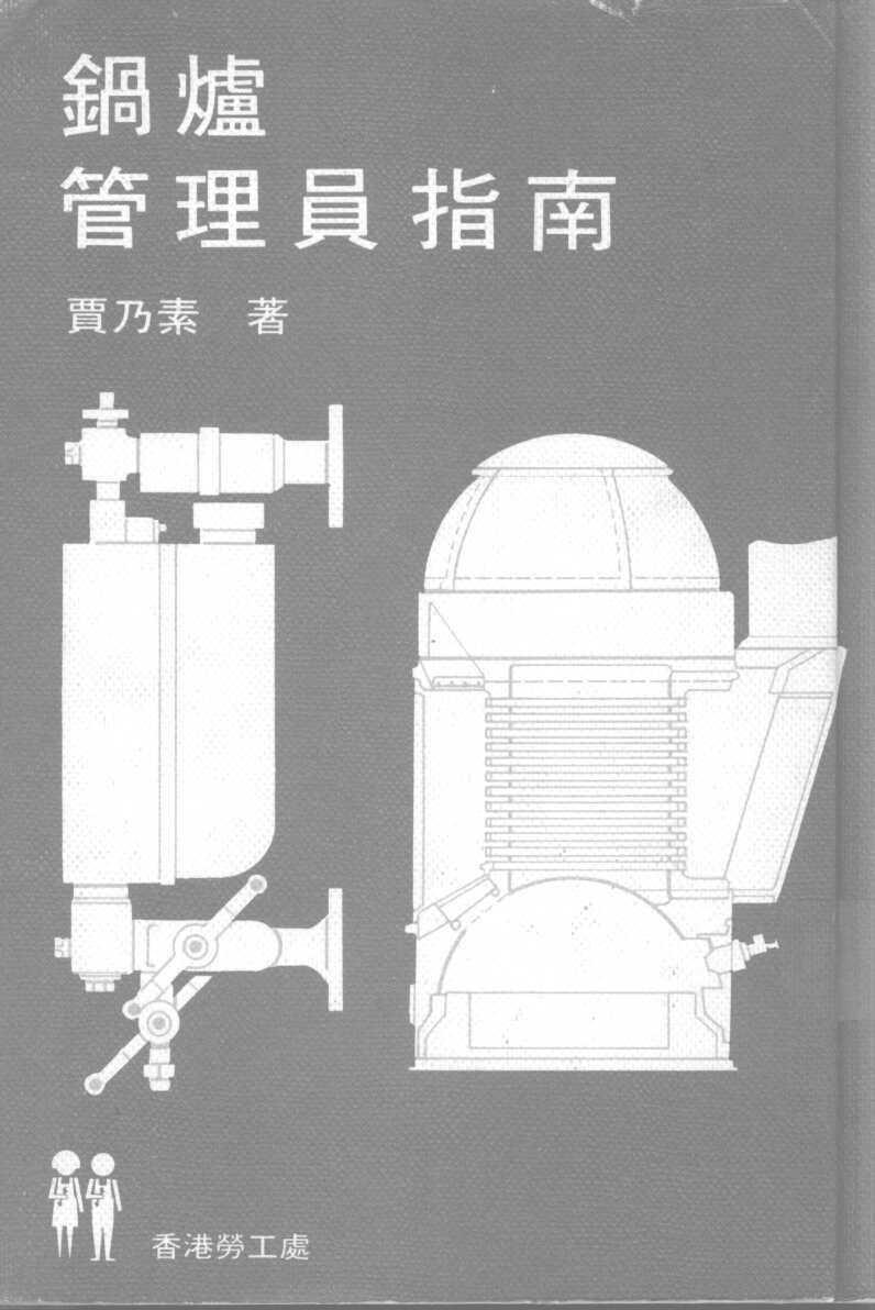
199
CHAPTER 2: PROPERTIES OF STEAM AND STEAM POWER
 CHAPTER 2: PROPERTIES OF STEAM AND STEAM POWER Steam produced from water forms one of the most important working fluids in engineering energy conversion systems. The advantages of using steam (water) as
Boiler Mountings. Engr. Omar Sadath, Maritme Lecturer & Trainer, Bangladesh
 Boiler Mountings Engr. Omar Sadath, Maritme Lecturer & Trainer, Bangladesh overview Mountings are crucial without which the operation of boilers is unsafe. Proper maintenance and care of the mountings
Boiler. Fire tube Boiler:
 Boiler What is Boiler? A closed metallic vessel in which the water is heated beyond the boiling temperature by the application of heat by the combustion of fuels to convert it into steam. The function
AIM OF THE EXPERIMENT:- Study of boilers (fire tube, water tube) APPARATUS REQUIRED: - SL.NO NAME OF THE APPARATUS SPECIFICATION QUANTITY 01 Fire tube
 APPARATUS REQUIRED: - SL.NO NAME OF THE APPARATUS SPECIFICATION QUANTITY 01 Fire tube") LABORATORY MANUAL ON STUDY OF FIRE TUBE AND WATER TUBE BOILERS Prepared By Prof. (Dr.) M. K. Roul Professor and Principal, Gandhi Institute for Technological Advancement (GITA), Bhubaneswar 752054 June
LABORATORY MANUAL ON STUDY OF FIRE TUBE AND WATER TUBE BOILERS Prepared By Prof. (Dr.) M. K. Roul Professor and Principal, Gandhi Institute for Technological Advancement (GITA), Bhubaneswar 752054 June
MODEL ANSWER FOR ELEMENTS OF MECH.ENGG.(17413) 1) steam boiler- It is a closed vessel in which steam is produced from water by combustion of fuel.
 1) steam boiler- It is a closed vessel in which steam is produced from water by combustion of fuel.") MODEL ANSWER FOR ELEMENTS OF MECH.ENGG.(17413) Q 1. a) 1) steam boiler- It is a closed vessel in which steam is produced from water by combustion of fuel. 2) steam turbine- It is a device that extract
MODEL ANSWER FOR ELEMENTS OF MECH.ENGG.(17413) Q 1. a) 1) steam boiler- It is a closed vessel in which steam is produced from water by combustion of fuel. 2) steam turbine- It is a device that extract
LATTNER BOILER COMPANY 9.5 HP Low-NOx Installation and Start-Up Checklist for Dry Cleaners
 1 1. General Installation Information (to be completed by technician) Date installed: Location (city & state): Cleaner s name: National Board number (boiler): Installed by (company): Installed by (technician):
!!! Sample Written Program For Your Company. For BOILER SAFETY. Provided By:!!!
 Sample Written Program For Your Company For BOILER SAFETY Provided By: P.O. Box 2136 Slidell, LA 70458 Phone: 985-781-1444 Fax: 985-781-1446 Email: info@se-safety.com Purpose Boiler Safety Program The
Steam and Gas Power Systems Prof Ravi Kumar Department of Mechanical and Industrial Engineering Indian Institute of Technology - Roorkee
 Steam and Gas Power Systems Prof Ravi Kumar Department of Mechanical and Industrial Engineering Indian Institute of Technology - Roorkee Module No # 02 Lecture No # 09 Boilers Mountings and Accessories
Presentation On Industrial Boiler Operation And Maintenance
 Presentation On Industrial Boiler Operation And Maintenance Supervised By: Engr. Poresh Kanti Das GM-MAL RIP, Mulgoan, Kaligonj, Gajipur Boiler fundamental. Assessment On Heat recovery Boiler. Boiler Operation.
Development of Boiler Design
 Development of Boiler Design Learning Outcome When you complete this module you will be able to: Discuss historical developments of, and the general requirements for proper boiler design. Learning Objectives
INSTRUCTION MANUAL FOR OIL BURNER MODELS
 INSTRUCTION MANUAL FOR OIL BURNER MODELS X500 Bio B10 E90-803-001-001-00 Rev 7-1 - Contents Technical specifications Technical data... 3 Working field... 3 Dimensions... 4 Head and electrode settings...
INSTRUCTION MANUAL FOR OIL BURNER MODELS
 INSTRUCTION MANUAL FOR OIL BURNER MODELS X500-2 Low voltage 12v dc Brushed motor E90-803-001-005-01 Rev 4-1 - Contents Technical specifications Technical data...3 Working field...3 Dimensions...4 Head
INSTRUCTION MANUAL FOR OIL BURNER MODELS
 INSTRUCTION MANUAL FOR OIL BURNER MODELS X400 Bio B10 E90-803-001-001-03 Rev 13-1 - Contents Technical specifications Technical data... 3 Working field... 3 Dimensions... 4 Head and electrode settings...
There are two devices used together for heating crude oil in petroleum refinery as in figure (1), and these devices are:
, and these devices are:") Heating of Crude Oil 1.Introduction: There are two devices used together for heating crude oil in petroleum refinery as in figure (1), and these devices are: Heat Exchangers. Tube Still Heaters (Furnaces).
Heating of Crude Oil 1.Introduction: There are two devices used together for heating crude oil in petroleum refinery as in figure (1), and these devices are: Heat Exchangers. Tube Still Heaters (Furnaces).
Steam Fundamentals. (in heating & processing applications)
") Steam Fundamentals (in heating & processing applications) Introduction Common Heat Energy conveyers: Thermal Oil Hot water Steam Electrical Electric Heaters Electrodes (High Current) Steam Fundamentals
Steam Fundamentals (in heating & processing applications) Introduction Common Heat Energy conveyers: Thermal Oil Hot water Steam Electrical Electric Heaters Electrodes (High Current) Steam Fundamentals
Low pressure boiler* inspection and maintenance
 2-12.001 May 2011 Low pressure boiler* inspection and maintenance Introduction Even as our society evolves into a more technologically advanced, economically driven environment, many businesses and their
.2 Section Waste Management and Disposal..4 Section Vibration Isolation and Seismic Control Measures.
 Issued 2005/06/01 Section 15510 Packaged Boilers Page 1 of 13 PART 1 GENERAL 1.1 RELATED SECTIONS.1 Section 01330 Submittal Procedures..2 Section 01355 Waste Management and Disposal..3 Section 01780 Closeout
! WARNING. McDonnell & Miller Installation & Maintenance Instructions MM-315(C)
") Models 51, 51-S and 53 Boiler Water Feeders Models 51-2, 51-S-2 and 53-2 Feeder Cut-Off Combinations McDonnell & Miller Installation & Maintenance Instructions MM-315(C) OPERATION Maximum Water Supply
Models 51, 51-S and 53 Boiler Water Feeders Models 51-2, 51-S-2 and 53-2 Feeder Cut-Off Combinations McDonnell & Miller Installation & Maintenance Instructions MM-315(C) OPERATION Maximum Water Supply
MULTIPLEX SELF RECUPERATIVE gas burner
 Installation - Maintenance MULTIPLEX SELF RECUPERATIVE gas burner SERIES MPSR The Nu-way Multiplex Recuperative System offers the alternative of a self-recuperative burner or a separate recuperator and
Conversion Instructions Logano G234X. Gas boiler. Please read carefully before installing and servicing. Gas boiler
 Gas boiler UPON COMPLETION OF THE INSTALLATION THE INSTALLER MUST INSTRUCT THE OWNER AND OPERATOR ON THE FUNCTIONALITY AND THE PROPER OPERATION OF THE BOILER AND THE HEATING SYSTEM. INSTALLER MUST REVIEW
Eclipse Self-Check UV Scanner
 856 Instruction Manual 10/18/2010 Eclipse Self-Check UV Model 5602-91 Version 1 Introduction The self-check UV is used for continuous gas or oil flames. A mechanical shutter in the scanner closes briefly
Eclipse 90 UV Scanner Model A Version 1
 85 Instruction Manual 10/14/010 Eclipse 90 UV Model 5600-90A Version 1 C US Introduction This sensor features a high sensitivity ultraviolet (UV) tube for monitoring gas or oil flames that cycle on and
Diocese of Cleveland Facilities Services Corporation
 Diocese of Cleveland Facilities Services Corporation BOILER MAINTENANCE and SERVICING SEASONAL MAINTENANCE - to be performed by trained boiler technician or boiler contractor only: 1. Disassemble the low
THE ALLIANCE FOR BANGLADESH WORKER SAFETY BOILER SAFETY
 THE ALLIANCE FOR BANGLADESH WORKER SAFETY BOILER SAFETY 1 Boiler Room Hazards A Risk Of Explosion Exists High Pressure steam Combustion Gases Chemicals Moving Machinery Hot Surfaces www.bangladeshworkersafety.org
A hydronic system controls comfort by delivering heated or cooled fluid to the conditioned space through pipes.
 Introduction to Hydronics A hydronic system controls comfort by delivering heated or cooled fluid to the conditioned space through pipes. Hydronic heating systems use hot water or steam to deliver the
PIPING SYSTEM EQUIPMENTS
 PIPING SYSTEM EQUIPMENTS Introduction Equipments are devices that provide power, process and store materials. Equipments in piping systems depend on the specific industries using them. Specialized equipment
FLAME115 INFRARED HEATER SERVICE MANUAL INDEX FIRE 115 WARNING
 FLAME115 INFRARED HEATER SERVICE MANUAL INDEX 1. CONTROLS AND COMPONENTS 2. FLAME CONTROL CYCLES 3. MAINTENANCE SCHEDULE 4. TROUBLESHOOTING GUIDE 5. REPAIR PROCEDURES 1. FAN MOTOR ASSEMBLY 2. FUEL FILTER
Technical Data TYPE T14 & T14D TEMPERATURE PILOT SPENCE ENGINEERING COMPANY, INC. 150 COLDENHAM ROAD, WALDEN, NY SD 4511A T14 PILOT
 Technical Data SD 4511A SPENCE ENGINEERING COMPANY, INC. 150 COLDENHAM ROAD, WALDEN, NY 12586-2035 TYPE T14 & T14D TEMPERATURE PILOT PRINTED IN U.S.A. SD 4511A/9811 5 13 /16 D 4 7 /8 1 13 /16 T14 PILOT
Indirect gas-fired air heater
 Indirect gas-fired air heater SERIES HD INSTALLATION AND SERVICE MANUAL MANUFACTURED BY : BROTHERS LIMITED WARNING Improper installation, modification, adjustment or maintenance may cause damage, injury
THERMAL ENGINEERING & GAS DYNAMICS ME-6002
 SAGAR INSTITUTE OF RESEARCH & TECHNOLOGY, BHOPAL DEPARTMENT OF MECHANICAL ENGINEERING THERMAL ENGINEERING & GAS DYNAMICS ME-6002 1 UNIT I STEAM GENERATOR SYLLABUS Steam generators: classification, conventional
UV Scanner. Model Specification. Introduction. 854 Instruction Manual
 854 Instruction Manual 10/11/010 UV Model 5600-91 C US Introduction This sensor features a high temperature and high sensitivity ultraviolet (UV) tube for monitoring gas or oil flames in applications that
Boiler Draft Equipment
 Boiler Draft Equipment Learning Outcome When you complete this module you will be able to: Discuss, sketch and describe the basic equipment used to supply combustion air to a boiler furnace. Learning Objectives
ROTARY DRYER CONSTRUCTION
 ROTARY DRYER The Rotary Dryer is a type of industrial dryer employed to reduce or to minimize the liquid moisture content of the material it is handling by bringing it into direct contact with a heated
Direct Fired Heater Model AD Specification
 Direct Fired Heater Model AD Specification Description A Direct-fired gas heating and ventilating unit(s), as indicated on the drawings shall be furnished. Unit(s) shall be tested in accordance with ANSI
Boiler Basics. Design and operation
 Boiler Basics Design and operation A boiler is an enclosed vessel that provides a means for combustion heat to be transferred into water until it becomes heated water or steam. The hot water or steam under
POWER VENTER SYSTEM. Model: PVO-300, PVO-600
 POWER VENTER SYSTEM Model: PVO-300, PVO-600 Included is one ETL and cetl listed Power Venter to be used primarily with a single 120VAC controlled oil fired furnace, boiler, or water heater. The PVO may
PVE SERIES POWER VENTER SYSTEM MANUAL
 PVE SERIES POWER VENTER SYSTEM MANUAL Contents Page I. Typical Venting System Components 2 II. System Operation 3 III. Power Venter Sizing 3,4 IV. Installation Safety Instructions 5,6 V. Installation of
Internet Version for Reference Only INDUCED DRAFT COMMERCIAL WATER HEATERS SUPPLEMENT INSTRUCTIONS TO PART #
 INDUCED DRAFT COMMERCIAL WATER HEATERS SUPPLEMENT INSTRUCTIONS TO PART #238-39387-00 THIS INSTRUCTION SUPPLEMENT IS ONLY INTENDED TO GIVE INSTALLATION INSTRUCTIONS AND INFORMATION RELATED TO THE INDUCED
Internal ridged board 1" x 1.5 foil face installation shall be installed on roof, walls and base of casing.
 A-D WITH MPU SPECIFICATION WRITTEN SPECIFICATION Description A Modular Packaged Heating, Cooling and ventilating unit(s), as indicated on the drawings shall be furnished. Direct Fired Gas Unit(s) shall
SECTION HEATING BOILERS
 SECTION 23 52 00 HEATING BOILERS PART 1 - GENERAL 1.1 SUMMARY A. Section includes boilers, controls and boiler trim, steam and condensate connections, hot water connections, fuel burning system and connections,
Installation & Maintenance Manual
 Installation & Maintenance Manual MOL 200 S1L (B30A) Oil Burner 11/12 Tel: +44 (0) 1905 794331 Fax: +44 (0) 1905 794017 Email: info@nu-way.co.uk Web: www.nu-way.co.uk DESCRIPTION COMPONENTS 1. Shrouded
ASSSIGNMENT 3. Textbook Assignment: Boilers, chapter 4, pages 4-1 through 4-15, and Steam Turbines, chapter 5, pages 5-1 through 5-1.
 ASSSIGNMENT 3 Textbook Assignment: Boilers, chapter 4, pages 4-1 through 4-15, and Steam Turbines, chapter 5, pages 5-1 through 5-1. 3-1. What is the function of a boiler in the steam cycle? 1. To convert
TECHNICAL MANUAL ASGX
 TECHNICAL MANUAL ASGX MEDIUM/HIGH PRESSURE HOT WATER BOILER INDEX 1 TECHNICAL CHARACTERISTICS... 2 1.1 GENERAL... 2 1.2 TECHNICAL DATA... 2 2 ACCESSORIES... 3 2.1 PRESSURE... 3 Pressure gauge... 3 Operation
Installation & Service Instructions for Jackson & Church Flexaire Packaged Furnaces SDF-125 thru SDF-400 Gas Firing
 Installation & Service Instructions for Jackson & Church Flexaire Packaged Furnaces SDF-125 thru SDF-400 Gas Firing Important: To protect the unit and avoid damage to the heat exchanger, the blower speed
INTRODUCTION THIS MANUAL INCLUDES IMPORTANT SAFETY INFORMATION
 INSTALLATION AND OPERATING INSTRUCTIONS FOR THE HARDY Fuel Oil Furnace Models D-140 & D-350 HARDY MANUFACTURING COMPANY, INC. 12345 ROAD 505 PHILADELPHIA, MS 39350 PHONE: (601) 656-5866 FAX: (601) 656-4559
Forced draught gas burner
 Installation, use and maintenance instructions Forced draught gas burner Code Model Type 3751982 GAS 3 519T80 291 (3) - 02/2010 DECLARATION Declaration of conformity in accordance with ISO / IEC 17050-1
SECTION PACKAGED, OUTDOOR, CENTRAL-STATION AIR-HANDLING UNITS
 SECTION 237413 - PACKAGED, OUTDOOR, CENTRAL-STATION AIR-HANDLING UNITS PART 1 - GENERAL 1.1 SUMMARY A. This Section includes packaged, outdoor, central-station air-handling units (rooftop units) with the
Ball Float Controlled. Thermo Dynamic(TD) Trap Safety Valve Condensate Pump Flash Vessel Moisture Separators Deaerator Head Steam Injector Sight Glass
 Trap Safety Valve Condensate Pump Flash Vessel Moisture Separators Deaerator Head Steam Injector Sight Glass") Product of Quality Best Performance Ball Float Controlled Steam Traps Auto Drain Traps Float Valve Air Vent Valves Feed Control Valve Drain Control Valve Thermo Dynamic(TD) Trap Safety Valve Condensate
Product of Quality Best Performance Ball Float Controlled Steam Traps Auto Drain Traps Float Valve Air Vent Valves Feed Control Valve Drain Control Valve Thermo Dynamic(TD) Trap Safety Valve Condensate
SECTION HEATING BOILER FEEDWATER EQUIPMENT
 SECTION 23 53 00 HEATING BOILER FEEDWATER EQUIPMENT PART 1 - GENERAL 1.1 SUMMARY A. Section includes boiler feedwater pumps, de-aerators, accessories, controls and tanks. 1.2 REFERENCES A. ASME (American
Series 47 and 247 Mechanical Water Feeders. Series 47-2 and Combination Mechanical Water Feeder/Low Water Cut-Off ! WARNING
 Series 47 and 247 Mechanical Water Feeders McDonnell & Miller Installation & Maintenance Instructions MM-316(C) Series 47-2 and 247-2 Combination Mechanical Water Feeder/Low Water Cut-Off Series 47 Water
OPERATING AND MAINTENANCE MANUAL
 OPERATING AND MAINTENANCE MANUAL NVPOM-0104 TABLE OF CONTENTS Section Page 1 SPECIFICATIONS...1 1.1 Nova Plus Specifications...1-1 1.2 Warranty...1-2 2 GENERAL BURNER DESCRIPTION...2 2.1 Burner...2-1 2.2
INSTALLATION, OPERATION AND MAINTENANCE MANUAL FOR COMMERCIAL INDIRECT POWERED WATER HEATER
 INSTALLATION, OPERATION AND MAINTENANCE MANUAL FOR COMMERCIAL INDIRECT POWERED WATER HEATER ELECTRIC HEATER COMPANY BASE MODEL T Edition 0 HUBBELL ELECTRIC HEATER COMPANY P.O. BOX 88 STRATFORD, CT 0665
LGB Gas fired boiler
 LGB Gas fired boiler Control Supplement LGB-5 Series 2 Propane gas CSD-1 Control System Part Number 550-110-682/0304 Please read this page first Hazard definitions To the installer... The following terms
Heat Exchanger. The purpose may be either to remove heat from a fluid or to add heat to a fluid.
 HEAT EXCHANGERS Heat Exchanger Heat exchanger is an apparatus or an equipment in which the process of heating or cooling occurs. The heat is transferred from one fluid being heated to another fluid being
Columbia Boiler Company
 EMG Series Boilers Available in Natural Gas & Propane Rev 12012 Columbia Boiler Company PO Box 1070 Pottstown, PA 19464 Tel (610) 473-8457 Fax (610) 367-6800 Website www.columbiaboiler.com Email cbcsales@ptd.net
The equipment and materials shall be designed and constructed in accordance with the ASME code section I 2001 ED A02 and Chinese Standards.
 Steam Boiler Type S50-3.82/450 Traveling grate stoker 50t/h x 3.82 pa x 450 Degree C 1. Basic use of the boiler The boiler can be used for industrial power generation, or thermal power station for enterprises
Solution of I Mid Term Steam Engineering 6ME5A
 1(a) Discuss the working principle of LaMont high pressure boiler This boiler works on basic principle of forced convection. If the water is circulate by a pump inside the tube, the heat transfer rate
B.Tech. First Semester Examination Basics of Mechanical Engineering (ME-101F)
") B.Tech. First Semester Examination Basics of Mechanical Engineering (ME-101F) Q. 1. (a) Differentiate between water tube boiler and fire tube boiler. Ans. Comparison Between 'Fire-tube and Water tube'
B.Tech. First Semester Examination Basics of Mechanical Engineering (ME-101F) Q. 1. (a) Differentiate between water tube boiler and fire tube boiler. Ans. Comparison Between 'Fire-tube and Water tube'
MODELS N150/300/675/900/1500/2500/2600 INSTALLATION, SERVICING AND MAINTENANCE INSTRUCTIONS
 MODELS N150/300/675/900/1500/2500/2600 INSTALLATION, SERVICING AND MAINTENANCE INSTRUCTIONS 1. FEATURES The Type N Trap range is particularly suitable for high pressure/high temperature trapping applications
Module 5: Combustion Technology. Lecture 38: Combustion Burners
 1 P age Module 5: Combustion Technology Lecture 38: Combustion Burners 2 P age Keywords : Atmospheric burner, atomizer, rotating cup burner, swirl type burner, nozzle design 5.7 Combustion Burners Types
UV Flame Supervision System
 7 783 UV Flame Supervision System DETACTOGYR LFE50 Series 02 ISO 9001 The LFE50 is a self-checking UV flame supervision system designed for use with continuously operating burners or for burners running
When you complete this module you will be able to: Describe various watertube boiler designs, including large generating units.
 Watertube Boilers Learning Outcome When you complete this module you will be able to: Describe various watertube boiler designs, including large generating units. Learning Objectives Here is what you will
Steam The Primary Force
 HOW POWER PLANTS WORK Lesson One Steam The Primary Force 11101 4 Lesson 1 Steam The Primary Force TOPICS Energy for Power Plants Converting Energy to Electricity The Importance of Air in Combustion Removing
FIREYE C9707A ALL FUEL SCANNER
 65-8065 APRIL 11, 2013 FIREYE C9707A ALL FUEL SCANNER The C9707A All Fuel Scanner is used with the FIREYE R9107A Flame Controller to provide continuous monitoring of burner flames in industrial and utility
Ball-Type Faucet. Handle. Set screw. Adjusting ring. Cap. Spout. Cam Tab. Rubber cam seal Ball Rubber inlet seal Spring
 1 P LUMBING Ball-Type Faucet Handle Set screw Adjusting ring Cap Spout Inside the faucet body is a hemispherical recess with a fixed alignment pin and three holes: a cold-water inlet, a hot-water inlet,
BASIC BOILERS NAME :- DATE :-
 BASIC BOILERS NAME :- DATE :- This examination was conducted under conditions that allowed a fair and honest test of the candidate s knowledge and ability. Exam supervisor C:\Tassie Steam\N01basicboiler
21 20 LITER GAS FRYER FFA3200 INSTALLATION AND SERVICING.
 21 20 LITER GAS FRYER FFA3200 INSTALLATION AND SERVICING www.anvilworld.com 20 ALL ANVIL EQUIPMENT COMES WITH A ONE YEAR WARRANTY ON COMPONENTS AND DEFECTIVE WORKMANSHIP. www.anvilworld.com 19 20 LITER
POWER VENTER. Model: PVE Series
 POWER VENTER Model: PVE Series CONTENTS Typical Venting System Components... System Operation... Power Venter Sizing... Installation Safety Instructions... Installation of Power Venter... Connecting Power
TOTALPAC2 Integrated Fire Protection System
 TOTALPAC2 Integrated Fire Protection System Page 1 of 8 General 1. Applicable Standards The TOTALPAC2 Surefire complies with the following standards: - NFPA-13 Sprinkler Systems; - NFPA-15 Water Spray
Rotary Oil Burner Construction
 Rotary Oil Burner Construction 133 CHAPTER 17 Rotary Oil Burner Construction The construction of this type burner whose basic principles and essential elements were presented in the preceding chapter are
CHAPTER 3 BASIC STEAM CYCLE
 CHAPTER 3 BASIC STEAM CYCLE To understand steam generation, you must know what happens to the steam after it leaves the boiler. A good way to learn the steam plant on your ship is to trace the path of
PART 0 A/E INSTRUCTIONS 0.01 DESIGN REQUIREMENTS
 PART 0 A/E INSTRUCTIONS 0.01 DESIGN REQUIREMENTS A. General: 1. To obtain maintenance and repair standards for boiler burners (Section 15555A) and boiler tubes (Section 15555B), contact the DPS Project
Service for Automatic Controls
 Service for AutomaticControls 269 CHAPTER 28 Service for Automatic Controls This section is designed to give dealers, installation and service men practical information on the electrical controls used
OPERATING AND MAINTENANCE MANUAL FOR VERTICAL IMMERSION HEATED STEAM BOILERS. Technical Control Systems Limited MODELS "VIHS"
 OPERATING AND MAINTENANCE MANUAL FOR VERTICAL IMMERSION HEATED STEAM BOILERS Technical Control Systems Limited MODELS "VIHS" Technical Control Systems Ltd Treefield Industrial Estate Gildersome, Leeds
USER'S MANUAL PGE Single Package Rooftop
 USER'S MANUAL PGE Single Package Rooftop Gas Heating/Electric Cooling Units Sizes 036-150 3 to 12-1/2 Tons NOTE TO INSTALLER: This manual should be left with the equipment owner. WARNING: If the information
 RAYBURN SUPREME/NOUVELLE/355S USER INSTRUCTIONS ISSUE 4 Water Temperature Control Stat. http://www.oilstoves.co.uk/ 1 2 Contents 1. Introduction. 1 2. How Does it Operate? 1 3. Description of Controls.
ClearFire. Startup Guide. Model CFH. Horizontal Steam Boiler
 ClearFire Model CFH Horizontal Steam Boiler Startup Guide 750-293 www.cleaverbrooks.com Improper installation, adjustment, service, or maintenance can cause equipment damage, personal injury, or death.
MODEL HS115-3, HS115-4 & HS115-5 WIRING DIAGRAM ADDENDUM
 TJERNLUND PRODUCTS, INC. 1601 Ninth Street White Bear Lake, MN 55110-6794 PHONE (800) 255-4208 (651) 426-2993 FAX (651) 426-9547 Visit our web site www.tjernlund.com MODEL HS115-3, HS115-4 & HS115-5 WIRING
SUPER HIGH EFFICIENCY WATER HEATERS SUPPLEMENT TO INSTRUCTION MANUAL P/N (Replaces pg. 2 in instruction manual.) CONGRATULATIONS!
 CONGRATULATIONS!") SUPER HIGH EFFICIENCY WATER HEATERS SUPPLEMENT TO INSTRUCTION MANUAL P/N 238-44219-00 (Replaces pg. 2 in instruction manual.) CONGRATULATIONS! You have just purchased one of the finest water heaters on
SUPER HIGH EFFICIENCY WATER HEATERS SUPPLEMENT TO INSTRUCTION MANUAL P/N 238-44219-00 (Replaces pg. 2 in instruction manual.) CONGRATULATIONS! You have just purchased one of the finest water heaters on
ST 40 Oil Burner. Installation & Maintenance Manual
 ST 40 Oil Burner Installation & Maintenance Manual 178 093 13 Thank you for choosing a Nu-way burner. As you would expect from a Company who has a pedigree of more than 75 years in the heating industry,
! WARNING. McDonnell & Miller Installation & Maintenance Instructions MM-214(C) Series 61 Low Water Cut-Off OPERATION
 Series 61 Low Water Cut-Off OPERATION") Series 61 Low Water Cut-Off Typical Applications: - Primary or secondary low water cut-off for hot water and steam boilers. - Low water cut-off - High water cut-off - Alarm actuator OPERATION Maximum Boiler
Series 61 Low Water Cut-Off Typical Applications: - Primary or secondary low water cut-off for hot water and steam boilers. - Low water cut-off - High water cut-off - Alarm actuator OPERATION Maximum Boiler
Power Flame Incorporated
 Power Flame Incorporated SUGGESTED SPECIFICATION FOR MODEL NVC2 THRU NVC6 ULTRA LOW NOx GAS BURNERS SUB 9 PPM NOx WITH CONTROLINKS CONTROLS THE POWER TO MANAGE ENERGY 2001 South 21st Street, Parsons, Kansas
A. Product Data: Include rated capacities, furnished specialties and accessories.
 BASE BID: SECTION 15542 FUEL-FIRED RADIANT HEATERS PART 1 - GENERAL 1.1 SUMMARY A. Furnish and install a Co-Ray-Vac Low Intensity Vented Infrared Radiant Vacuum Gas Heating System. System must be certified
USER S INFORMATION MANUAL
 USER S INFORMATION MANUAL HOT WATER HEATING BOILERS DOMESTIC WATER HEATERS 150,000-300,000 Btu/hr MODELS EB-EWU-02 IMPORTANT INSTALLER - AFFIX INSTALLATION MANUAL ADJACENT TO THE BOILER CONSUMER - RETAIN
OPERATING AND MAINTENANCE MANUAL FOR ELECTRIC STAINLESS STEEL HEATER FOR DEIONIZED (DI) WATER ELECTRIC HEATER COMPANY BASE MODEL D
 WATER ELECTRIC HEATER COMPANY BASE MODEL D") OPERATING AND MAINTENANCE MANUAL FOR ELECTRIC STAINLESS STEEL HEATER FOR DEIONIZED (DI) WATER ELECTRIC HEATER COMPANY BASE MODEL D HUBBELL ELECTRIC HEATER COMPANY P.O. BOX 288 STRATFORD, CT 06615 PHONE:
OPERATING AND MAINTENANCE MANUAL FOR ELECTRIC STAINLESS STEEL HEATER FOR DEIONIZED (DI) WATER ELECTRIC HEATER COMPANY BASE MODEL D HUBBELL ELECTRIC HEATER COMPANY P.O. BOX 288 STRATFORD, CT 06615 PHONE:
Fully-automatic Gas tankless Water Heater USER'S MANUAL FOR MODEL EZ-101 ISO9001 certified
 Fully-automatic Gas tankless Water Heater USER'S MANUAL FOR MODEL EZ-101 ISO9001 certified Thank you for purchasing our fully-automatic gas-fired tankless water heater. Please completely read this Manual
MECHANICAL ENGINEERING ME.2017 FUNDAMENTAL OF REFRIGERATION AND AIR CONDITIONING. Sample Questions and Answers
 MECHANICAL ENGINEERING ME.2017 FUNDAMENTAL OF REFRIGERATION AND AIR CONDITIONING Sample Questions and Answers CHAPTER 5 EVAPORATORS 1. What is Evaporator? Classify the various types of evaporator. Evaporator
SECTION AUXILIARY HEATER
 14-301.03/ 1 2010MR12 SECTION 14-301.03 GENERAL DESCRIPTION The Thermo 300 auxiliary heating system is used in conjunction with the vehicle s heating system, in order to heat the passenger compartment
INSTALLATION, OPERATING & MAINTENANCE INSTRUCTIONS FOR 350 SERIES CIRCULATION HEATERS
 INDEECO Circulation Heaters are designed to provide years of trouble free operation if properly installed and maintained. Please read and follow these instructions for installing and maintaining the heater.
GP COMBUSTION EQUIPMENT INC 100 Sheldon Dr., Units 16/17 Cambridge, Ontario N1R 7S7. Model C Forced Draft Burners. Natural Gas or Propane MODEL C10
 Model C Forced Draft Burners Natural Gas or Propane MODEL C10 MODEL C4 GP COMBUSTION EQUIPMENT INC 100 Sheldon Dr., Units 16/17 Cambridge, Ontario N1R 7S7 Telephone: (519) 620-0230 Telefax: (519) 620-0232
Installation Instructions
 Model 500-SP OVENPAK Burners Page 2300-S-1 Installation Instructions General Instructions Important: Do not discard packing material until all loose items are accounted for. To prevent damage in transit,
PACKAGED COMMERCIAL WATERTUBE BOILERS
 PACKAGED COMMERCIAL WATERTUBE BOILERS PACKAGED COMMERCIAL WATERTUBE BOILER American Boiler Manufacturers Association 4001 N. 9 th Street, Suite 226 Arlington, VA 22203-1900 703/522-7350 2003, American
LFE50. UV Flame Safeguard. Building Technologies Division DETACTOGYR
 7 783 DETACTOGYR Flame Safeguard The... together with the QRA50M / QRA51M form a self-checking flame supervision system (DETACTOGYR ) designed for use with continuously operating oil or gas burners or
INDITHERM. Low temperature gas burners
 INDITHERM Low temperature gas burners 1-2.3-1 High turndown for maximum operation flexibility. Maximum capacities up to 1800 kw. Designed for firing in indirect fired processes. Excellent combustion throughout
Fig.: macroscopic kinetic energy is an organized form of energy and is much more useful
 Harnessing Energy Fig.: macroscopic kinetic energy is an organized form of energy and is much more useful Vapor Power Cycle The vast majority of electrical generating plants are variations of vapor power
ELECTRONIC FLAME SUPERVISION MULTI-BURNER
 MULTI-BURNER MODEL: SENS-A-FLAME II Revision: 0 7112 DESCRIPTION Model 7112 Sens-A-Flame II is a second generation solid-state programmable combustion safeguard for supervising multiple burner ovens, furnaces,
VENTING CLEARANCES. BBT NORTH AMERICA Bosch Group. Bosch Water Heating 340 Mad River Park, Waitsfield, VT TWH-V-26 page 1 of 6 rev 01/06
 page 1 of 6 VENTING CLEARANCES The vents should not be obstructed and all joints properly fitted. Floors, ceilings and walls must be cut or framed to provide necessary clearance to vents. Metal strippings
15 20 kw kw kw
 Burner Set-up Details 15 20 kw 20 26 kw 29 36 kw Riello RDB2 Please read these instructions carefully before commissioning and using this appliance. To be retained by the householder HEALTH AND SAFETY
(Information about THERMAL dampers for gas-fired appliances available on request.) WARNING
 WARNING") FLAIR INTERNATIONAL CORPORATION 600 OLD WILLETS PATH HAUPPAUGE, NEW YORK 11788 U.S.A. TEL.: (516) 234-3600 FAX: (516) 234-3610 SPECIFICATIONS, INSTALLATION INSTRUCTIONS AND TROUBLE-SHOOTING GUIDE FOR STACK
FLAIR INTERNATIONAL CORPORATION 600 OLD WILLETS PATH HAUPPAUGE, NEW YORK 11788 U.S.A. TEL.: (516) 234-3600 FAX: (516) 234-3610 SPECIFICATIONS, INSTALLATION INSTRUCTIONS AND TROUBLE-SHOOTING GUIDE FOR STACK
BuildingName The Description of the Project P DOCUMENTS
 ARCHITECTURE, ENGINEERING AND CONSTRUCTION P00000000 0000 DOCUMENTS ARCHITECTURE & ENGINEERING 326 East Hoover, Mail Stop B Ann Arbor, MI 48109-1002 Phone: 734-764-3414 Fax: 734-936-3334 SPECIFICATION