Twister / Twister venturi
|
|
|
- Jacob Rose
- 5 years ago
- Views:
Transcription


1 Twister / Twister venturi Nr / /A Ideas for dental technology
2

3 mm 0,4 Inch 5 6


4


5 C B A 17 H I K G D F E 18 E B C A D

6
 27 28")
7 25 26 b) a)
8 31 32
9 Twister / Twister venturi No / 1827 ENGLISH Content Introduction...1 Symbols...2 Instruction manual 1. Commissioning Setup Recommendations Wall Mounting Benchtop Models Electrical connection Compressed air supply Operation Appliance Description Key Symbols Display On / Off Standby mode Setting Mixing Parameters Mixing Process Abort mixing process Power cut Adjustment During the Mixing Process Cleaning and Maintenance Housing Seal Surfaces Changing suction filter system Sponge filter Sinter filter Changing fuses Changing inlet filter Changing the silencer Spare Parts Standard Delivery Delivery Versions Accessories Troubleshooting Twister (No. 1826) Twister venturi (No. 1827) Error codes...9 Information for the purchaser A. Application A.1 Correct use of the appliance A.2 Unapproved use...11 A.3 Ambient conditions...11 B. Hazards and warnings...11 C. Approved personnel...11 D. Prior to installation E. Repair F. Disposal instructions F.1 Disposal instructions for countries in the EU G. Technical data G.1 Twister (No. 1826) G.2 Twister venturi (No. 1827) H. Disclaimer I. Guarantee Introduction We are delighted that you have opted to buy the Twister (no. 1826) / Twister venturi (no. 1827) vacuum mixer. This appliance sets new standards of functionality, performance, and ergonomics. To guarantee long and troublefree use please read the following instruction manual carefully and always follow the included safety notices. Please use this information to brief operators on how to use this appliance and about possible applications and potential hazards during use. This user information should be made available to the operator at all times. Further information can be found in the Information for the purchaser section at the end of this manual EN
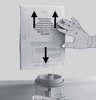
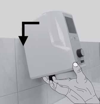
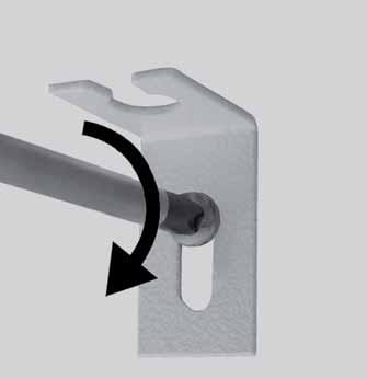
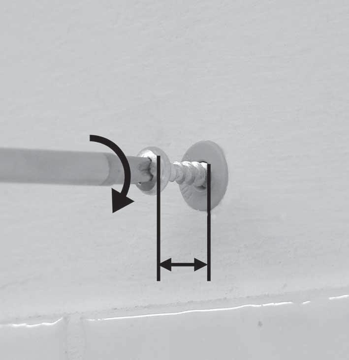
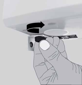
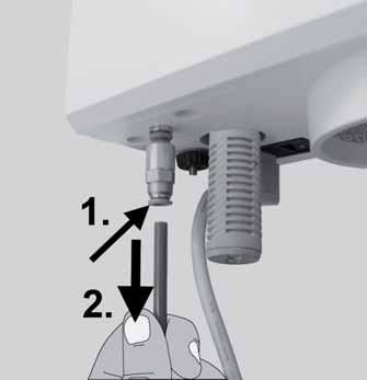
10 Symbols This manual contains symbols also found on the appliance itself with the following meaning: Danger! Immediate risk of injury. Please observe accompanying documentation! High Voltage! Danger high voltage. Caution Risk of damage to the appliance if the instruction is not followed. Notice A general notice that improves and eases use. For indoor use only. Disconnect from mains supply before opening the appliance. The appliance complies with applicable EU directives. Within the EU, this device is subject to the provisions of the directive 2002/96/EG (WEEE directive). Other symbols are explained when displayed. Instruction manual 1. Commissioning 1.1 Setup Recommendations Operate the appliance at room temperature 15-30ºC [59 86ºF]. When setting up the appliance, please note the following: Do not place the appliance under a heat source. Do not place the appliance in front of open windows. Do not set the appliance up where it will be subjected to direct sunlight. Do not subject the appliance to high humidity. 1.2 Wall Mounting Please have the following items on hand: pencil, drill template, Phillips head screwdriver, drill drill bit 8 mm [5/16th inch] - appropriate for the wall material. Make sure the wall on which you intend to mount the device is capable of bearing its weight. Please ensure that there are no electric cables or water pipes running through the wall at the place of installation! 1. Establish optimum working height (Fig. 1). 2. Align the drill template and mark the drill holes (Fig. 2). 3. Drill the required holes >>> depth at least 55 mm [2.2 inch]. 4. Insert the dowels (Fig. 3). 5. Screw the top screws into the dowels. Allow the screws to protrude 9-10 mm [ inch] (Fig. 4). 6. Screw the lower mounting bracket into place (Fig. 5). 7. Hang the appliance on the wall (Fig. 6). 8. Secure the device by tightening the knurled nut (Fig. 7). Tighten the knurled nut securely. EN - 2 -
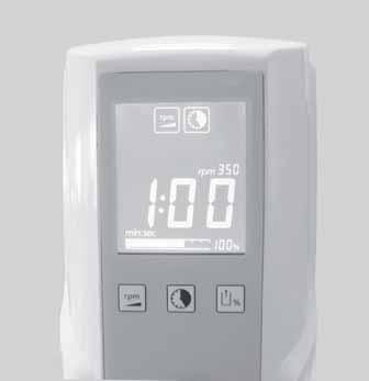
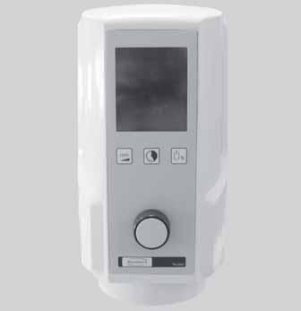
11 1.3 Benchtop Models The stand (Fig. 8) can be used to convert the vacuum mixer to a floor-mounted appliance. 1. Position the stand on a level surface. 2. Hang the appliance in the stand (Fig. 9). 3. Secure the appliance by tightening the knurled nut (Fig. 7). Tighten the knurled nut securely. The stand is not part of the standard delivery and must be ordered as an optional accessory (refer to section 7. Accessories ). 1.4 Electrical connection Ensure the mains supply and voltage marked on the nameplate is identical. Secure the mains cable through the cable safety catch (Fig. 10). Plug mains cable into socket on appliance (Fig. 11). Plug in at the mains (Fig. 12). 1.5 Compressed air supply Twister venturi only 1. Attach the compressed air tube into the tube connector of the input filter as far as it will go (Fig. 13). There will be a slight resistance to overcome when attaching. 2. Select the proper coupling from the set provided and install it on the other hose end to connect it to the compressed air system (Fig. 14). 3. Connect to compressed air line system (Fig. 15). The best vacuum performance is attained at the operating pressure specified in the technical data (see section G.2). Use filter pressure regulator if necessary (see section 7. Accessories ). The vacuum mixer is now ready for operation. 2. Operation 2.1 Appliance Description (Fig. 16) / (Fig. 17) A Control knob (set mixing parameters, start, stop, aerate) B Parameter keys C Display D Appliance switch E Fuse F Appliance socket G Suction filter system Twister venturi only H Silencer I Inlet filter K Compressed air connection 2.2 Key Symbols Mixing parameters Symbol Adjustment range Mixing time 0:00-9:55 min:sek Speed /min Vacuum *) 80 / 100 **) % Factory setting 1: *) Twister, no. 1826: in 5% increments **) Twister venturi, no. 1827: Choice of 80% and 100% vacuum levels only. 2.3 Display The following will appear on the display (Fig. 18): A Large-scale display of parameter (here: mixing time) / (here: remaining mixing time) B Parameter symbols. The symbol vacuum only shows when less than 100% vacuum has been set. C Selected speed D Selected vacuum level E Current vacuum level (bar graph) EN
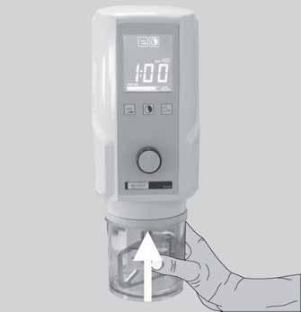
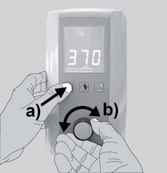
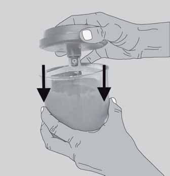
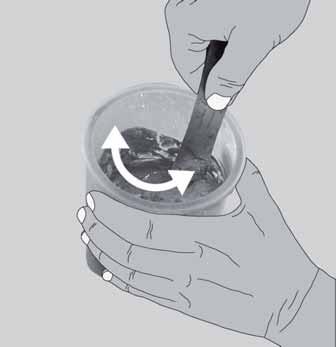
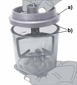
12 2.4 On / Off The appliance is switched on and off at the switch (D, Fig. 17). The mixing parameters last used will reappear in the display when the appliance is switched on. The factory settings will appear the first time the appliance is switched on (see section 2.2) STANDBY MODE The appliance will go into standby mode if no button is pressed or it stands idle for more than three minutes. The display will be dimmed when this happens. To leave the standby mode: Press any parameter key. Turn the control knob. Press the control knob. Couple the mixing bowl to the appliance. The mixing parameters last used will reappear in the display. 2.5 Setting Mixing Parameters Procedure for changing a mixing parameter: 1. Press parameter key (Fig. 19a). The parameter key symbol is shown in the display. The parameter value is displayed in large-scale characters. 2. Turn the control knob to change the value (Fig. 19b). The new value is saved immediately. There is no need to press any key to confirm the change. In initial state the mixing time is always displayed in large-scale characters and can also be changed directly without pressing the parameter key. TIP - Setting the Vacuum: Tests with various investment materials have shown that the best mixing results (smooth, homogeneous casting results) are obtained at the maximum vacuum setting. As a rule, this also applies to plasters. In individual instances, independent tests have shown that - under extremely high vacuum the partial pressure in the mixing bowl can sink to a point where bubbles due to boiling can form in certain plasters. Then reduce the vacuum setting. 2.6 Mixing Process Always read the safety data sheets supplied by the manufacturers when mixing investment materials! Wear the appropriate personal protective equipment as and when required! Observe maximum mark on mixing bowl. Do not fill the mixing bowl over the maximum mark. This limit is valid for powders and liquids measured before mixing. If the mixing bowl is over-filled the suction filter system can become soiled. Attempting to mix small quantities in large bowls will result in inadequate mixing. 1. Set mixing parameters as instructed by the manufacturer. 2. Select an appropriate mixing bowl size. 3. Mix powder and liquid as instructed by the manufacturer. Allow plaster to sit for approx sec. 4. Using a spatula, lightly mix the materials together (Fig. 20). 5. Install the appropriate paddle (Fig. 21). Make sure the bowl rim (Fig. 22a) and cover rim (Fig. 22b) are clean. 6. Couple the mixing bowl to the appliance (Fig. 23) When the bowl is added the motor runs briefly in order to engage the paddle. 7. Vacuum generation starts automatically. EN - 4 -
13 Do not let go until the bowl stays in place alone and vacuum level bar has passed the halfway mark (Fig. 24a)! If the set vacuum is <100%, the pump will switch off when it is achieved. If the set vacuum is <100% then the pump can continue to run for a short time, in order to reach the set vacuum level exactly. Twister venturi only The reduced vacuum level (80%) is achieved through an opened bypass. This is why it sounds similar to when 100% vacuum is achieved. 8. Start the mixing process. Press the control knob (Fig. 24b). The remaining mixing time (countdown) is displayed during the mixing process. By delaying the start of the mixing process, a prevacuum can be achieved. 9. The appliance beeps when the mixing cycle has finished. The time which has elapsed since the end of the mixing cycle is shown in the display. 10. Aerate bowl. Hold the bowl! Press the control knob. The bowl will be released in a few seconds. 11. Remove the mixing bowl Tip: Only mix the same type of material in a given bowl. Residue form previous mixing processes can have a negative influence (e.g., silicon fails to harden, etc.). We recommend a separate bowl for each type of material (plaster, investment, silicon). Use the adhesive labels enclosed to the mixing bowl ABORT MIXING PROCESS 1. Stop the mixing process. Press the control knob once. The appliance will beep. Mixing process being aborted 2. Aerate bowl. Hold the bowl! Press the control knob. The bowl will be released in a few seconds. 3. Remove the mixing bowl POWER CUT Twister only If a power cut should occur or the appliance is switched off during a mixing operation, the vacuum will be maintained and the bowl will stay on the device. When the power returns or the device is switched back on again, the bowl will become ventilated and then fall off. Twister venturi only In case of a power failure or if the appliance is switched off, the bowl will be vented and be uncoupled. 2.7 Adjustment During the Mixing Process All the mixing parameters can be displayed in large-scale characters during the mixing process if you press the relevant parameter key. The parameters can also be changed during the mixing process by pressing the relevant parameter key and turning the control knob. Changes made to the mixing parameter settings during the mixing process will be applied to that mixing process only and will not be saved EN
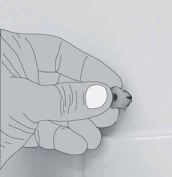
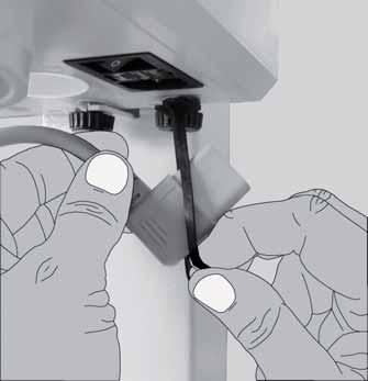
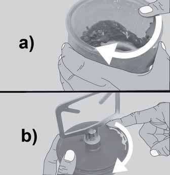
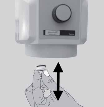
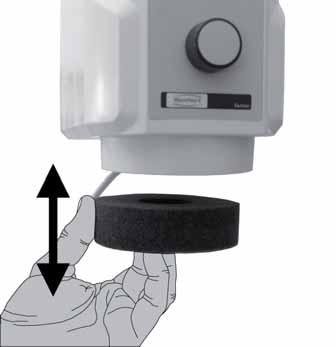
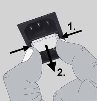
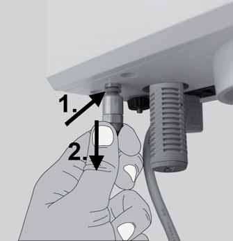
14 3. Cleaning and Maintenance Switch off and unplug the appliance before cleaning or servicing. 3.1 Housing Do not steam clean the appliance. Do not use solvent-based, aggressive or scouring cleaners. 1. Switch the appliance off. 2. Disconnect from mains. 3. Wipe housing with a damp cloth. 3.2 Seal Surfaces The following seal surfaces must always be kept clean in order to ensure correct vacuum built up and the secure retention of the mixing bowl during the mixing process: Seal between the appliance and the paddle (Fig. 25a). Seal between the paddle and the bowl (Fig. 25b). Tip: You should regularly coat the rubber seals with Vaseline. This will significantly increase their service life and optimize to appliance s function 3.3 Changing suction filter system The suction filter system consists of a sponge filter (Fig. 26a) and a sinter filter (Fig. 26b). Vacuum can only build-up in a clean suction filter system. Never operate the device without the complete suction filter! SPONGE FILTER Pull the sponge filter out in the direction of the base and replace with a new sponge filter (Fig. 27) SINTER FILTER 1. Pull the sponge filter out in the direction of the base. 2. Pull the sinter filter out in the direction of the base and replace with a new sinter filter (Fig. 28). Press the sinter filter in as far as it will go. 3. Replace the sponge filter. The sinter filter can also be cleaned in the ultrasonic bath. (Recommendation: Plaster solvent GO-2011, Art. no ). 3.4 Changing fuses Before replacing a fuse, disconnect the appliance from the mains. Never use a fuse of larger impedance. 1. Switch the appliance off. 2. Disconnect from mains. 3. Unlatch the fuse holder on both sides and remove (Fig. 29). 4. Change blown fuse. 5. Replace the fuse holder by sliding back into the socket until both sides lock into place. 3.5 Changing inlet filter Twister venturi only 1. Disconnect the appliance from the compressed air supply. 2. Press the ring on the intake filter up and pull the compressed air hose off (Fig. 30). 3. Press the ring on the compressed air coupling up and pull the intake filter off (Fig. 31). 4. Insert a new intake filter to the compressed air coupling, passing the point of slight resistance. 5. Insert the compressed air hose to the new intake filter, passing the point of slight resistance. 6. Reconnect the appliance to the compressed air supply. EN - 6 -
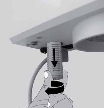
15 Frequent intake filter blockage is an indication of contaminated compressed air. In such cases we recommend the upstream installation of a filter pressure regulator (see section 7. Accessories ). 3.6 Changing the silencer Twister venturi only 1. Unscrew and remove silencer (Fig. 32). 2. Fit and screw in new silencer. 4. Spare Parts Refer to the spares list at the end of this manual for numbers of wearing and replacement parts. 5. Standard Delivery 1 Vacuum mixer ml bowl, incl. blunger 1 Mains cable 1 Compressed air hose, 2 m (Twister venturi only) 1 Pneumatic connection set (Twister venturi only) 1 Operating instructions 1 Drill template 1 Fastening set 1 Repalcement sponge filter 6. Delivery Versions Twister, 230 V, Hz Twister, V, Hz Twister venturi, 230 V, Hz Twister venturi, V, Hz 7. Accessories Stand for benchtop device WxHxD: 227 x 622 x 294 mm [8,937 x 24,488 x 11,575 inch] Mixing spatula Bowl incl. blunger, 65 ml Blunger, 65 ml Bowl, 65 ml Bowl incl. blunger, 200 ml Blunger, 200 ml Bowl, 200 ml Bowl incl. blunger, 500 ml Blunger, 500 ml Bowl, 500 ml Bowl incl. blunger, 700 ml Blunger, 700 ml Bowl, 700 ml Bowl incl. blunger, 1000 ml Blunger, 1000 ml Bowl, 1000 ml Alginate Mixing bowl 500ml, incl. paddle Filter pressure regulator EN
16 8. Troubleshooting 8.1 Twister (No. 1826) Error Cause Solution ON/OFF switch Power not connected. Check the power supply. fails to work. Device fuse blown. Replace the fuse (Sec. 3.4). Motor fails to Motor fault. Have the device repaired. start. No, or insufficient vacuum (not in Suction filter system plugged. Have filter cleaned or changed (Sec. 3.3). the green range Seal surfaces dirty. Clean the seal surfaces (Sec. 3.2). on the scale). Solenoid valve fault. Have the device repaired. Vacuum pump fault. Have the device repaired. Vacuum release / venting, too slow. Suction filter system plugged. Have filter cleaned or changed (Sec. 3.3). Solenoid valve fault. Have the device repaired. Vacuum pump doesn t start. Bowl detection pin sticking. Clean area around pin. Have the device repaired. The vacuum pump At <100% vacuum, the None switches on and off intermittently during the mixing process. vacuum pump will switch off once the set vacuum has been reached. If the vacuum should drop due to seepage, the vacuum pump will automatically switch back on until the set vacuum level has been reached. 8.2 Twister venturi (No. 1827) Error Cause Solution ON/OFF switch Power not connected. Check the power supply. fails to work. Device fuse blown. Replace the fuse (Sec. 3.4). Motor fails to Motor fault. Have the device repaired. start. No, or insufficient Compressor switched Switch the compressor on. vacuum. off. Operating pressure too low or too high. Check dynamic operating pressure (see technical data, Sec. G.2). Switch off other consumers. Compressed air hose not connected, leaky or bent. Check the hose. Air hose too long. Maximum length 2 m. Square are of air hose Minimum inner diameter 4 mm. too small. Suction filter system plugged. Have filter cleaned or changed (Sec. 3.3). EN - 8 -
17 Error Cause Solution Seal surfaces dirty. Clean the seal surfaces (Sec. 3.2). Inlet filter plugged. Change inlet filter (Sec. 3.5). Silencer plugged. Replace the silencer (Sec. 3.6). Connect filter pressure regulator in series. Solenoid valve fault. Have the device repaired. Venturi nozzle plugged. Have the device repaired. Vacuum release / venting, too slow. Suction filter system plugged. Have filter cleaned or changed (Sec. 3.3). Silencer plugged. Replace the silencer. (Sec. 3.6) Connect filter pressure regulator in series. Solenoid valve fault. Have the device repaired. No vacuum being generated. Bowl detection pin sticking. Clean area around pin. Have the device repaired. Permanent venting Solenoid valve fault. Have the device repaired. noise. Bowl detection pin stick- ing. Clean area around pin. Have the device repaired. Fluttering noise from the silencer. Working pressure too low. Check dynamic operating pressure (see technical data, Sec. G.2). 8.3 Error codes The following indications will be given if the electronic system detects an error: A warning signal will sound The display will flash alternately Err and an error code. End of error display: Press control button (except for Err 3, 5 and 6) Err 3, 5 and 6: Switch device off, follow advice in section power failure. With Err 5 it may no longer be possible to remove the mixing bowl. With an error code as shown in the following table, please proceed as advised. Error code Cause Solution Err. 2 Minimum vacuum level not yet reached Vacuum level has dropped below 500 mbar. Ventilate bowl and remove (see section 2.6.1, points no. 2 and 3) If the error recurs: Have the device repaired EN
18 Error code Cause Solution Err. 3 The vacuum is built-up too quickly due to the fact that the suction system is blocked. Have filter cleaned or changed (Sec. 3.3). Err. 4 Motor fault. Ventilate bowl and remove (see Sec , points no. 2 and 3) Have the device repaired. Err. 10 Too much material Mixing time too long, the material has already begun to set. Ventilate bowl and remove (see section 2.6.1, points no. 2 and 3) Only fill the bowl to the maximum fill level. This limit is valid for powders and liquids measured before mixing. Ventilate bowl and remove (see section 2.6.1, points no. 2 and 3) Select shorter mixing times. For all other error codes: Note error code Have the device repaired. Quote the error code to the repair service Information for the purchaser The following information is intended to help purchasers ensure safe operation of this appliance in their laboratory. Instruct operators on the application, possible hazards during use and operation of this appliance based on the user information. Ensure that this user information is available to operators. A. Application A.1 Correct use of the appliance The Twister / Twister venturi vacuum mixer is designed solely for homogeneous, bubble-free mixing of dental casting and modelling materials such as plasters, investments, and silicones. EN
19 A.2 Unapproved use No accessories may be used on this appliance other than those supplied by Renfert. The use of other components is not approved and carries the risk of serious injury. A.3 Ambient conditions (according to DIN EN ) The appliance should only be operated: indoors up to 2,000 metres above sea level at an ambient temperature of 5ºC - 40ºC [41ºF - 104ºF] *) at a maximum relative humidity of 80% at 31ºC [87.8ºF], linear reduction up to 50% relative humidity at 40ºC [104ºF] *) with mains electricity supply provided that the voltage fluctuation is within 10% of the rated value with Pollution Degree 2 with Overvoltage Category II *) The appliance can be used at a temperature of 5ºC - 30ºC [41ºF - 86ºF] and at a humidity of up to 80%. At temperatures of 31ºC - 40ºC [87.8ºF - 104ºF] the humidity must reduce proportionately to ensure that the appliance can be operated (e.g. at 35ºC [95ºF] = 65% humidity, at 40ºC [104ºF] = 50% humidity). The appliance should not be operated at temperatures above 40ºC [104ºF]. B. Hazards and warnings Granted protection is not given any longer in case the appliance is not operated according to the instruction manual on hand. Only to be used indoors. The appliance is only intended for dry operation and should not be used or stored outdoors or in wet conditions. The appliance should only be operated using a mains cable with a country-specific plug system. Any modification required should only be carried out by an electrician. The appliance should only be operated if the data on the rating plate corresponds with the data of regional mains voltage. The appliance should only be plugged into earthed sockets. The mains socket should be easily accessible. Regularly check connecting cables and hoses (e.g. mains cable) for damage (e.g. kinks, tears, porosity) or deterioration. Do not operate appliances with damaged mains wires, hoses or other defects. The appliance should always be operated under supervision. Risk of injury! Risk of injury if the components used are not approved. Always use original Renfert components. Always read the safety data sheets supplied by the manufacturers when mixing investment materials! Wear the appropriate personal protective equipment as and when required! Never mix flammable or explosive materials. Never connect the paddle without the mixing bowl. Manipulating the automatic bowl coupler and the intake opening can result in damage to the device and personal injury Switch off the appliance when work is complete. Switch off and unplug the appliance before carrying out repairs and servicing work on electrical components. Switch off and unplug the appliance before cleaning or servicing it. C. Approved personnel The appliance may only be operated and serviced by trained personnel EN
20 D. Prior to installation Compare the data on the rating plate with the data of the regional mains voltage before installation. The appliance should only be plugged into earthed sockets. Maintain sufficient distance from steam blasting equipment. E. Repair Repairs should only be carried out by qualified personnel. Repairs to the electrical equipment, which are not specified in these operating instructions, should only be carried out by an electrician. Switch off and unplug the appliance before carrying out repairs and servicing work on electrical components. F. Disposal instructions The appliance should be disposed of by a specialist firm. The specialist firm should be informed of any hazardous residue in the appliance. F.1 Disposal instructions for countries in the EU To conserve and protect the environment, prevent environmental pollution and improve the recycling of raw materials, the European Commission adopted a directive that requires the manufacturer to accept the return of electrical and electronic appliances for proper disposal or recycling. Within the European Union appliances with this symbol should not therefore be disposed of in unsorted domestic waste. For more information regarding proper disposal please apply at your local authorities. G. Technical data G.1 Twister (No. 1826) Mains voltage: 230 V / Hz V / Hz Power consumption: 180 VA Device fuse: T4AL, 250VAC Speed: /Min LpA *) (idling): < 70 db(a) Dimensions (WxHxD): 105 x 285 x 235 mm 4,13 x 11,22 x 9,55 inch Weight: 5,2 kg (w./o. bowl) G.2 Twister venturi (No. 1827) Mains voltage: 230 V / Hz V / Hz Power consumption: 180 VA Device fuse: T4AL, 250VAC Speed: 100 bis 450 1/Min Connection pressure: 5-6,5 bar Air consumption, approx.: 46 l/min. LpA *) (idling): < 70 db(a) Dimensions (WxHxD): 105 x 285 x 235 mm 4,13 x 11,22 x 9,55 inch Weight: 4,0 kg (w./o. bowl) *) sound pressure level in accord. with EN ISO H. Disclaimer Renfert GmbH is not liable for claims for compensation or claims under guarantee if: the product is used for purposes other than those stated in the operating instructions the product is modified in any way apart from modifications described in the operating instructions the product has not been repaired by a specialist firm or original Renfert replacement parts have not been used there is continued use of the product despite obvious safety defects or damage EN
21 the product has been subjected to mechanical knocks or has been dropped. I. Guarantee Renfert gives a 3-year guarantee on all parts of the Twister / Twister venturi provided that the product is used in accordance with the operating instructions. The original sales invoice of the specialist depot is required for a claim under guarantee. Parts subject to natural wear and tear and also consumables (e.g., blungers, mixing bowls, and suction filter system...) are not covered by the guarantee. The guarantee is rendered void in the case of incorrect use, non-adherence to the operating, cleaning, servicing or connection instructions, repairs carried out by the owner or repairs that are not carried out by a specialist firm, use of replacement parts from another manufacturer or unusual or unapproved uses not specified in the user guidelines. Successful claims under guarantee do not extend the guarantee period. Subject to alteration EN
Bedienungsanleitung. Ideas for dental technology. Made in Germany C
 Bedienungsanleitung 216604 C 01022013 Made in Germany Ideas for dental technology GLISH Instruction manual 1. Introduction...1 1.1 Employed Symbols...1 2. Safety...2 2.1 Intended use...2 2.2 Improper use...2
Millo / Millo pro. Nr x000 / 1805-x000. Ideen für die Dentaltechnik A
 Millo / Millo pro Nr. 1804-x000 / 1805-x000 0609 21-6543 A Ideen für die Dentaltechnik 1 2 3 4 5 6 7 8 9 10 11 12 Millo / Millo pro No. 1804-x000 / 1805-x000 ENGLISH Content Introduction... 15 Symbols...
Millo / Millo pro. Nr x000 / 1805-x000
 Millo / Millo pro Nr. 1804-x000 / 1805-x000 Bedienungsanleitung Instruction manual Mode d emploi Istruzioni d uso Instrucciones de servicio Инструкция по эксплуатации 操作说明书 取扱説明書 사용설명서 21-6543 05012016
Millo / Millo pro. Nr x000 / 1805-x000
 Millo / Millo pro Nr. 1804-x000 / 1805-x000 Renfert GmbH Industriegebiet 78247 Hilzingen / Germany Tel. +49 7731 8208-0 Fax +49 7731 8208-70 info@renfert.com www.renfert.com Made in Germany 0208 21-6543
Silent TS. Nr / Ideas for dental technology / A. Made in Germany
 Silent TS Nr. 2921-0050 / 2921-1050 21-9191 30102012 / A Made in Germany Ideas for dental technology 1 2 3 4 5 6 7 8 9 10 11 12 13 14 15 16 17 18 19 20 21 22 23 24 25 26 27 28 29 30 31 Silent TS Nr. 2921-0050
Silent TS. Nr / Content Introduction...1 Symbology...1 Information for Operators...2. Introduction.
 Silent TS Nr. 2921-0050 / 2921-1050 ENGLISH Content Introduction...1 Symbology...1 Information for Operators...2 Operating Instructions 1. Setup and Commissioning...2 1.1 Setup... 2 1.2 Connection to the
SILENT compact /
 SILT compact 2934 0000 / 2934 1000 TRANSLATION OF THE ORIGINAL INSTRUCTIONS FOR USE Made in Germany Ideas for dental technology 21-2245 21052015 / A Contents 1. Introduction...3 1.1 Symbols...3 2. Safety...3
SILENT V4 TRANSLATION OF THE ORIGINAL INSTRUCTIONS FOR USE. Made in Germany
 SILT V4 TRANSLATI OF THE ORIGINAL INSTRUCTIS FOR USE Made in Germany 21-6669 26092016 1. Introduction... 2 1.1 Symbols... 2 2. Safety... 3 2.1 Intended Use... 3 2.2 Improper Use... 3 2.3 Ambient Conditions
Silent V4 Nr
 Silent V4 Nr. 2933 0000 DE FR IT ES 21-6669 12052014 / A Made in Germany Ideas for dental technology Silent V4 Nr. 2933 0000 GLISH 1. Introduction... 2 1.1 Symbols... 2 2. Safety... 3 2.1 Intended Use...
Vacu-Mixer. Operating Instructions
 Vacu-Mixer Operating Instructions Table of Content 1. Safety Instructions 2. Introduction 3. Installation 4. Charging 4.1 LED display in charging 5. Operation 5.1 Operating Elements 5.2 Inserting the Cartridge
Silent TS2 Nr /
 Silent TS2 Nr. 2930 0050 / 2930 1050 21-6670 18032013 / Made in Germany Ideas for dental technology Silent TS2 Nr. 2930 0050 / 2930 1050 Content 1. Introduction...2 1.1 Symbols...2 2. Safety...3 2.1 Intended
VPMmini. Operator's Manual
 VPMmini Operator's Manual Whip Mix Corporation 361 Farmington Ave. P.O. Box 17183 Louisville, KY 40217-0183 USA 502-637-1451 800-626-5651 Fax 502-634-4512 www.whipmix.com Features The Whip Mix VPMmini
GB Operating instructions
 Scope of delivery/device components 1 Carrier for suction nozzles 2 Dust bin 3 Release button (dust bin) 4 On/Off Switch 5 Motor casing 6 Rechargeable battery 7 Release buttons rechargeable battery 8 Swing
POLYMIX PX-IG 2000 Operating Instructions
 POLYMIX PX-IG 2000 Operating Instructions Voltage D 100-120V, 50/60 Hz D 210-250V, 50/60 Hz Please check that the voltage is correct and corresponds with the nameplate on the back of the machine. Manual
MeacoDry ABC Range Dehumidifiers
 MeacoDry ABC Range Dehumidifiers Thank you for choosing Meaco, we really do appreciate it INSTRUCTION MANUAL [EN] MeacoDry ABC range SAFETY INFORMATION ATTENTION This dehumidifier must not be used in rooms
User Manual GV25 GV35 GV702. Company information: Original instructions GV12066 (1)
") User Manual Original instructions GV25 GV35 GV702 Company information: www.vipercleaning.eu info-eu@vipercleaning.com GV12066 (1) 2012-04-10 USER MANUAL ENGLISH TABLE OF CONTENTS Introduction... 4 Manual
User Manual Original instructions GV25 GV35 GV702 Company information: www.vipercleaning.eu info-eu@vipercleaning.com GV12066 (1) 2012-04-10 USER MANUAL ENGLISH TABLE OF CONTENTS Introduction... 4 Manual
V 120 SG - V 160 SG. Instructions for use
 V 120 SG - V 160 SG Instructions for use Warning As the appliance contains a flammable refrigerant, it is essential to ensure that the refrigerant pipes are not damaged. The quantity and type of the refrigerant
Instructions for use
 Instructions for use These instructions are also available on the website: www.kitchenaid.eu Important instructions for safety 4 Installation 6 Safeguarding the environment 6 Troubleshooting guide 7 After-sales
INSTALLATION MANUAL GUTHD2. Universal Two Way Digital Thermostatic Valve for Shower Systems
 INSTALLATION MANUAL GUTHD2 Universal Two Way Digital Thermostatic Valve for Shower Systems IMPORTANT: To ensure this product is installed properly, you must read and follow these guidelines. The owner/
BWTC6510GL Cooker Hood 60 cm Glass cooker hood in stainless steel. BWTC9510GL Cooker Hood 90 cm Glass cooker hood in stainless steel
 User Manual for your BWTC6510GL Cooker Hood 60 cm Glass cooker hood in stainless steel BWTC9510GL Cooker Hood 90 cm Glass cooker hood in stainless steel NOTE: This User Instruction Manual contains important
Up to 60 Pint Commercial Grade DEHUMIDIFIER
 OWNER S MANUAL Up to 60 Pint Commercial Grade DEHUMIDIFIER Product #700834 IMPORTANT: After unpacking (or accidental tip-over) allow dehumidifier to stand upright for 20 minutes before starting. Contents
HG 675 CX 60 HG 675 CN 60 HG 675 CW 60
 HG 675 X 60 HG 675 CX 60 HG 675 CN 60 HG 675 CW 60 1 2 1. : 93/68: 90/396: 2006/95/CE: 2004/108/CE: - 1935/2004:. 2002/95/CE: RoHS 2.,.,,,,...,. (,..)..,,.,. ( ),,, ;,,.,.....,.,,,,,,...,. (..),,.,..,.,,,,
TTV 1500 / TTV 3000 OPERATING MANUAL CONVEYING FAN TRT-BA-TTV TC EN
 TTV 1500 / TTV 3000 EN OPERATING MANUAL CONVEYING FAN TRT-BA-TTV1500-3000-TC2016-26-004-EN Table of contents Notes regarding the operating manual... 2 You can download the current version of the operating
Specifications. Vacuum motor power consumption(w/hp) 1200 / 1.6. Exhaust water pump power consumption(w/hp 800 / 1.1
 1200 / 1.6. Exhaust water pump power consumption(w/hp 800 / 1.1") Specifications Rated voltage (V) AC 110-120V or 220-240V / 50-60Hz Vacuum motor power consumption(w/hp) 1200 / 1.6 Exhaust water pump power consumption(w/hp 800 / 1.1 Exhaust water pump flow (GPH/LPH)
Specifications Rated voltage (V) AC 110-120V or 220-240V / 50-60Hz Vacuum motor power consumption(w/hp) 1200 / 1.6 Exhaust water pump power consumption(w/hp 800 / 1.1 Exhaust water pump flow (GPH/LPH)
NEPTUN I Sole cleaning unit Art.-No.:
 Assembly and operating instructions Please read the instruction carefully before assembling and putting into operation. Keep instruction for future reference. Contents. General 2. Function 3. Installation
User and maintenance manual
 GB User and maintenance manual IMPORTANT SAFETY INSTRUCTIONS These instructions shall also be available on website: docs.whirlpool.eu. YOUR SAFETY AND THAT OF OTHERS IS HIGHLY IMPORTANT. This manual and
Whynter Portable Ice Maker 33 lb capacity - White
 Whynter Portable Ice Maker 33 lb capacity - White Model # : IMC-330WS INSTRUCTION MANUAL Congratulations on your new Whynter product. To ensure proper operation, please read this Instruction Manual carefully
Installation & Operating Guide
 HOT WATER DISPENSER Installation & Operating Guide Read all instructions thoroughly. Keep this guide for future reference. Proof of purchase is required for Warranty. Staple receipt or proof of purchase
GB User and maintenance manual
 GB User and maintenance manual IMPORTANT SAFETY INSTRUCTIONS These instructions shall also be available on website: docs.whirlpool.eu. YOUR SAFETY AND THAT OF OTHERS IS VERY IMPORTANT This manual and
PORTABLE AIR CONDITIONER
 PORTABLE AIR CONDITIONER Model: PEL00460 1 CONTENTS Page No. Details 2 Important Safety Information 3 Product Overview 3 Positioning & Installation 4 Installation Errors 4 Control Panel 5 Screen IMPORTANT
BWT6.3GL Cooker Hood 60 cm Glass chimney hood
 User Manual for your BWT6.3GL Cooker Hood 60 cm Glass chimney hood NOTE: This User Instruction Manual contains important information, including safety & installation points, which will enable you to get
OPERATING INSTRUCTIONS. for the heat press. Secabo TPD7 PREMIUM
 OPERATING INSTRUCTIONS for the heat press Secabo TPD7 PREMIUM Congratulations on the purchase of your Secabo heat press! Please carefully read the operating manual to easily integrate your unit into your
INSTRUCTION MANUAL MODEL: 690E
 1 INSTRUCTION MANUAL ALEKO Drywall Sander MODEL: 690E READ THROUGH CAREFULLY AND UNDERSTAND THESE INSTRUCTIONS BEFORE USE Visit our web site for more great products, parts and accessories: 2 3 4 5 6 Caution!
TIH 300 S / TIH 400 S / TIH 500 S / TIH 700 S / TIH 900 S / TIH 1100 S
 TIH 300 S / TIH 400 S / TIH 500 S / TIH 700 S / TIH 900 S / TIH 1100 S EN OPERATING MANUAL INFRARED HEATING PANEL TRT-BA-TIH300S-TIH400S-TIH500S-TIH700S-TIH900S-TIH1100S-TC-002-EN Table of contents Notes
For Models FF2310APS, FF2310APW, FF2310APB 55cm FREESTANDING FRIDGE FREEZER. Instruction Manual
 For Models FF2310APS, FF2310APW, FF2310APB 55cm FREESTANDING FRIDGE FREEZER Instruction Manual Please read these instructions carefully before use and retain for future reference. Before switching on your
High-Pressure Washer BY02-VBP-WTR BY02-VBP-WTH. CAUTION : Do not use this device before reading the instructions.
 High-Pressure Washer BY02-VBP-WTH BY02-VBP-WTR CAUTION : Do not use this device before reading the instructions. 1 1. Safety Instructions The appliance has been designed solely for private use outdoors
CTA15-2 warming drawer. operating and installation instructions
 CTA15-2 warming drawer operating and installation instructions Table of Contents GB-IE 1 PRECAUTIONS FOR USE...4 2 DISPOSAL INSTRUCTIONS - OUR ENVIRONMENT POLICY...5 3 SAFETY PRECAUTIONS...6 4 GET TO KNOW
G-10s. Instruction Manual. G-Series Cooler UPRIGHT COOLER. Part No.11IPA
 G-Series Cooler UPRIGHT COOLER Part No.11IPA-062800 Instruction Manual FOR YOUR FUTURE REFERENCE Thank you for using our product. This manual will guide you in getting the best use of your cooler. Remember
3/4 HP Model Trimmer Operating Instructions
 3/4 HP Model Trimmer Operating Instructions Whip Mix Corporation 361 Farmington Ave. P.O. Box 17183 Louisville, KY 40217-0183 USA 502-637-1451 800-626-5651 Fax 502-634-4512 www.whipmix.com Technical Specifications
G-7s. Instruction Manual. G-Series Cooler COUNTERTOP COOLER. Part No.11IPA
 G-Series Cooler COUNTERTOP COOLER Part No.11IPA-061000 Instruction Manual FOR YOUR FUTURE REFERENCE This easy-to-use manual will guide you in getting the best use of your cooler. Remember to record the
wc431 Slimline Integrated Dishwasher Manual for Installation, Use and Maintenance
 wc431 Slimline Integrated Dishwasher Manual for Installation, Use and Maintenance Contents Contents... 2 Important... 3 Important Notes... 4 Recommendations... 5 Before First Use... 5 Control Panel...
Induction Hob 2 YEAR GUARANTEE
 Induction Hob 2 YEAR GUARANTEE Model No. SDA-IH102BK-3GB THIS APPLIANCE IS FOR DOMESTIC USE ONLY READ ALL INSTRUCTIONS BEFORE USE. SAVE THESE INSTRUCTIONS FOR FUTURE REFERENCE. IMPORTANT SAFEGUARDS WHEN
MW402 Integrated Dishwasher
 MW402 Integrated Dishwasher Manual for Installation, Use and Maintenance 1 Customer Care Department The Group Ltd. Harby Road Langar Nottinghamshire NG13 9HY T : 01949 862 012 F : 01949 862 003 E : customer.care@cda.eu
Instructions for Use Warming Drawer. Bedienungsanweisung Wärmeschublade. Notice d'utilisation Chauffe-vaisselle. Gebruiksaanwijzing Servieswarmer
 Instructions for Use Warming Drawer Bedienungsanweisung Wärmeschublade Notice d'utilisation Chauffe-vaisselle Gebruiksaanwijzing Servieswarmer Table of Contents GB-IE 1 PRECAUTIONS FOR USE...4 2 DISPOSAL
FHA 1100 A1 Domestic Water Pump
 FHA 1100 A1 Domestic Water Pump Translation of original operation manual 6 Before reading, unfold the page containing the illustrations and familiarise yourself with all functions of the device. / Translation
EH0554 Indoor Climate Control
 EH0554 Indoor Climate Control 3.2kW heating or cooling capacity Air conditioning Dehumidification Cooling Efficient heating via air-source heat-pump Suitable for high- or low-wall installation No external
identity installation & maintenance instructions customer/technical services guarantee
 customer/technical services For any technical or installation queries please contact Vado on 01934 745163. guarantee This product is guaranteed against manufacturing defects from the date of purchase until
USER MANUAL. ICON60H Version 00. Vertical Glass Hood
 USER MANUAL ICON60H Version 00 Vertical Glass Hood [02] x 1 [01] x 1 [03] x 1 [04] x 1 [07] x 1 [05] x 1 [08] x 9 [06] x 1 [09] x 9 (4 x 30mm) [10] x 2 (3 x 10mm) Cooker hood Let's get started... These
EH0533 Indoor Climate Control
 EH0533 Indoor Climate Control 2.8 kw of cooling, 2.9 kw of heating Air Conditioning Efficient heating (air-source heat-pump) Cooling Remote control Suitable for low-wall installation No external unit required
UL U TR LTRASONIC S ONIC SCALE ALER PIEZO MINI
 ULTRASONIC SCALER PIEZO MINI CONTENTS XI - SYMBOLS 1. INTRODUCTION 1 Alternating current Type BF device 2. WARNINGS 1 3. PRESENTATION 1 3.1 Presentation 1 3.2 Technical description 2! Warning, please refer
AIRGOCLEAN 10 E OPERATING MANUAL AIR CLEANER TRT-BA-AIRGOCLEAN10E-TC-001-EN
 AIRGOCLEAN 10 E EN OPERATING MANUAL AIR CLEANER TRT-BA-AIRGOCLEAN10E-TC-001-EN Table of contents Notes regarding the operating manual... 1 You can download the current version of the operating manual and
TH100 Three in One Instant Hot Water Tap
 TH100 Three in One Instant Hot Water Tap Installation, Use and Maintenance Customer Care Department The Group Ltd. Harby Road Langar Nottinghamshire NG13 9HY T : 01949 862 012 F : 01949 862 003 E : customer.care@cda.eu
TTV 4500 / TTV 4500 HP / TTV 7000
 TTV 4500 / TTV 4500 HP / TTV 7000 EN OPERATING MANUAL AXIAL FAN TRT-BA-TTV4500-4500HP-7000-TC-003-EN Table of contents The current version of the operating manual can be found at: Notes regarding the operating
AOYUE INT. Advanced Repairing System NT 701A++ INSTRUCTION MANUAL. Correct Disposal of this product
 This appliance can be used by children aged form 8 years and above and persons with reduced physical, sensory or mental capabilities or lack of experience and knowledge if they have been given supervision
Suits all KPF849 models
 Kambrook - Australia Ground Floor, Suite 2, 170-180 Bourke Rd Alexandria NSW 2015, Australia Locked Bag 2000 Botany NSW 1455 Customer Service Line 1300 139 798 Customer Service Fax 1800 621 337 www.kambrook.com.au
ENGLISH INSTALLATION AND USER S MANUAL FRENCH NOTICE D INSTALLATION ET D UTILISATION ITALIAN MANUALE D ISTRUZIONE
 ENGLISH INSTALLATION AND USER S MANUAL FRENCH NOTICE D INSTALLATION ET D UTILISATION ITALIAN MANUALE D ISTRUZIONE 1 INSTALLATION AND USER S MANUAL CONTENT INTRODUCTION 03 SAFETY PRECAUTION 03 SPECIFICATION
MW001 Integrated Dishwasher. Manual for Installation, Use and Maintenance
 MW001 Integrated Dishwasher Manual for Installation, Use and Maintenance Important The CDA Group Ltd cannot be held responsible for injuries or losses caused by incorrect use or installation of this product.
Installation & Operating Guide
 5-036 HOT WATER TANK Installation & Operating Guide Read all instructions thoroughly. Keep this guide for future reference. Proof of purchase is required for Warranty. Staple receipt or proof of purchase
SOUND-INSULATED FAN. Iso-K OPERATION MANUAL. Iso-K_v.1(2)-EN.indd :20:59
-EN.indd :20:59") SOUND-INSULATED FAN OPERATION MANUAL _v.1(2)-en.indd 1 10.08.2015 15:20:59 CONTENT Introduction 3 General 3 Safety rules 3 Transport and storage requirements 3 Manufacturer's warranty 3 Fan design 4 Delivery
SOUND-INSULATED FAN OPERATION MANUAL _v.1(2)-en.indd 1 10.08.2015 15:20:59 CONTENT Introduction 3 General 3 Safety rules 3 Transport and storage requirements 3 Manufacturer's warranty 3 Fan design 4 Delivery
PJ130S High Pressure Cleaner
 PJ130S High Pressure Cleaner Operator Manual Original instructions WARNING: Do not use the machine without reading the instruction sheet. Item Description OVERVIEW 1. High pressure washer 2. On/off switch
INLINE СENTRIFUGAL FAN BOX BOX-R OPERATION MANUAL
 INLINE СENTRIFUGAL FAN BOX BOX-R OPERATION MANUAL CONTENT 3 Introduction 3 General 3 Safety rules 3 Storage and transportation rules 3 Manufacturer s warranty 4 Fan design 4 Delivery set 5 Technical data
Desoldering Tool. Instruction Manual
 Desoldering Tool Instruction Manual Thank you for purchasing the Hakko 472D desoldering tool with digital temperature display. Please read this manual before operating the Hakko 472D. Keep this manual
Operating instructions
 Operating instructions Built-in Plate Warmer EGW 2060 To prevent accidents and machine damage read these instructions before installation or use. UV M.-Nr. 06 405 620 Contents IMPORTANT SAFETY INSTRUCTIONS.................................
Automatic Mixer Operating Instructions
 English Automatic Mixer Operating Instructions PROTEC Medizintechnik GmbH & Co. KG Lichtenberger Strasse 35, D-71720 Oberstenfeld, Germany Telephone: +49-7062-9255-0 e-mail: service@protec-med.com Machine
Protein Skimmer 400 HO
 Protein Skimmer 400 HO US The sera marin Protein Skimmer 400 HO is a high performance, energy saving and flexibly usable dispergator skimmer for aquariums up to 400 l (06 US gal.). It can be used as a
Owner's Manual. Please read this document carefully before installing and/or using your vacuum cleaning system.
 Owner's Manual for household use only Please read this document carefully before installing and/or using your vacuum cleaning system. Model : Serial No : Important Safety Instructions When using an electrical
FD 430 Envelope Sealer
 FD 430 Envelope Sealer 1/2018 OPERATOR, MAINTENANCE, & PARTS MANUAL REV. 1 2 CONTENTS 1 SAFETY INSTRUCTIONS... 5 1.1 Symbols and reference key... 5 1.2 Basic safety precautions... 6 1.3 Safety advice...
Mobile Air Conditioner Instruction Manual Model TC-N9KM
 Mobile Air Conditioner Instruction Manual Model TC-N9KM Please read and retain these instructions for future reference SPECIFICATION Model no. Cooling capacity Power/Ampere consumption for cooling* Air
ascent Installation & maintenance instructions Customer/technical services Guarantee Mono basin filler with infrared sensor GUARANTEE REGISTRATION
 Customer/technical services For any technical or installation queries please contact Vado on 01934 745163. Guarantee This product is guaranteed against manufacturing defects from the date of purchase until
SMART EVO 2 - User Manual ELECTRICAL PANEL FOR 2 MOTORS
 SMART EVO 2 - User Manual ELECTRICAL PANEL FOR 2 MOTORS CONTENTS 1. INTRODUCTION... 5 2. WARNINGS... 6 3. GENERAL DESCRIPTION... 7 4. INSTALLATION... 8 5. LUMINOUS INDICATORS AND COMMANDS... 9 6. DIP-SWITCH
Koolbreeze. Portable Air-conditioner User s Manual. For Model : CLIMATEASY 14 P14HCP. Downloaded from manuals search engine
 Koolbreeze Portable Air-conditioner User s Manual For Model : CLIMATEASY 14 P14HCP Table of Contents 1. Installation.. 2 2. General Safety Reqirements.. 4 3. Product safety.... 5 4. Safety Awareness....
60cm Chimney Extractor
 60cm Chimney Extractor LAM2401 HJA2480 User & Installation Guide Contents Page Environmental note 3 IMPORTANT SAFETY INFORMATION 4 6 Specifications of your extractor 7 8 Dimensions 7 Specifications 7-8
BT16.4SS-HK BT19.4SS-HK Cooker Hood
 BT16.4SS-HK BT19.4SS-HK Cooker Hood User Manual for your Baumatic User Manual for your Baumatic BT16.4SS-HK 60 cm Chimney Hood BT19.4SS-HK 90 cm Chimney Hood NOTE: This User Instruction Manual contains
Vortex compact 3L Nr / -6000
 Vortex compact 3L Nr. 2924-5000 / -6000 Bedienungsanleitung Instruction manual Mode d emploi Istruzioni per l uso Instrucciones de servicio Инструкция по эксплуатации 操作说明书 取扱説明書 사용설명서 21-6583 30102017
Owner s Manual READ AND SAVE THESE INSTRUCTIONS
 16 Outdoor Misting / Oscillating Fan Model Number: AMMF16R-1 Owner s Manual READ AND SAVE THESE INSTRUCTIONS CAUTION: Before using this product, read this manual and follow all safety rules and operating
Register your new Bosch now:
 Register your new Bosch now: www.bosch-home.com/welcome ww.bos com/welcome BSGL5... en Operating instructions Table of content Safety information..................................4 Intended use.......................................4
LOCAL AIR CONDITIONER
 EN LOCAL AIR CONDITIONER OPERATING INSTRUCTIONS Read the instructions carefully before operating the appliance or carrying out maintenance work. Observe all the safety instructions; failure to observe
Instructions manual DEHUMID HP50
 Instructions manual DEHUMID HP50 Table of contents 1. Unpacking 3 2. Intended use 3 3. Disposal 3 4. Safety instructions 3 5. Functional principle 4 6. Automatic defrosting system 4 7. Set up and transportation
IMPORTANT SAFETY INSTRUCTIONS DANGER: WARNING:
 IMPORTANT SAFETY INSTRUCTIONS YOUR SAFETY AND THAT OF OTHERS IS PARAMOUNT This manual and the appliance itself provide important safety warnings, to be read and observed at all times. This is the attention
V-ZUG Ltd. Range hood. Levante. Operating instructions
 V-ZUG Ltd Range hood Levante Operating instructions Thank you for choosing to buy one of our products. Your appliance is made to high standards and is easy to use. Nevertheless, please take the time to
HKF 8180 Operating instructions
 Operating instructions EN Version 1.0en /Edition 05/2013 Contents 1 Important basic information... 3 1.1 Limitation of liability... 3 1.2 Operator's responsibilities... 3 1.3 Documentation... 3 1.3.1 Content
Utopian Split A/C. Thank you for purchasing this quality Split A/C system!
 Utopian Split A/C Thank you for purchasing this quality Split A/C system! Please read through this manual completely, and keep it in case you need to reference the information in the future. Any operation
MULTI - CYCLONIC VACUUM CLEANER VCC 7070
 MULTI - CYCLONIC VACUUM CLEANER VCC 7070 EN I J K A B C D E O P Q F G H L R S M N 3 ENGLISH 16-25 4 SAFETY Please read this instruction manual thoroughly prior to using this appliance! Follow all safety
DIRTY WATER SUBMERSIBLE PUMP
 WHAT S IN THE BOX DIRTY WATER SUBMERSIBLE PUMP 780W INSTRUCTION MANUAL SPECIFICATIONS Motor: 780W Max. Flow Rate: 15,700l/h Max. Head 8m Max. Immersion: 7m Min. Suction Depth 50mm Max Particle Size: Ø35mm
EN Variable Temperature Electric Kettle
 SWK 1890SS EN Variable Temperature Electric Kettle - 1 - EN Variable Temperature Electric Kettle Important safety instructions READ CAREFULLY AND STORE FOR FUTURE USE. This appliance may be used by children
Commercial backpack vacuum cleaner
 ORIGINAL INSTRUCTIONS CAUTION READ THESE INSTRUCTIONS BEFORE USING THE MACHINE User instructions Valet BackPack Commercial backpack vacuum cleaner 03-8113-0000 Issue 6 10/10 1 2 Contents 1. General information...
Table of Contents. English
 OM-E0799E 000 English Thank you for purchasing VIVA ace Motor Kit. Please read this Operation Manual and the VIVA ace Basic Set Operation Manual carefully before use for operating instructions and care
Instruction Manual Spray Booth SK 66
 Instruction Manual Spray Booth SK 66 TABLE OF CONTENTS page 1. Important safety instructions... 3 1.1. General information... 3 1.2. Safety instructions... 3 1.3. Safety instructions for operation.....
Portable Air Conditioner
 AC-12200E AC-12200H Portable Air Conditioner OWNER S MANUAL v1.0 Read and save these instructions. 2 A Name You Can Trust Trust should be earned and we will earn yours. Customer happiness is the focus
TDS 20 R / TDS 30 R / TDS 50 R
 TDS 20 R / TDS 30 R / TDS 50 R EN OPERATING MANUAL ELECTRICAL FAN HEATER TRT-BA-TDS20R-30R-50R-TC-001-EN Table of contents Notes regarding the operating manual... 1 Safety... 1 Information about the device...
MW401 Integrated Dishwasher
 MW401 Integrated Dishwasher Manual for Installation, Use and Maintenance Customer Care Department The Group Ltd. Harby Road Langar Nottinghamshire NG13 9HY T : 01949 862 012 F : 01949 862 003 E : service@cda.eu
Operating and installation instructions
 Operating and installation instructions Built-in plate warmer EGW 602-14 UV To prevent accidents and machine damage, read these instructions before installation or use. M.-Nr. 05 478 600 Contents Warning
THE MEDIX Actineb. Technical Specifications. % Particles < 5 um 75% * Class II BF. Intermittent (use for 60 Type Rating
 THE MEDIX Actineb Technical Specifications Operating Requirements 230v +/- 10%; 50Hz Dimensions & Weight 282 x 200 x 125; 2.3 Kg Particle Size 3.0 microns % Particles < 5 um 75% * Nebulisation Rate 0.3ml
Parenzo Range. Basin Mixer, Bath Filler & Bath Shower Mixer. Assembly instructions
 Parenzo Range Basin Mixer, Bath Filler & Bath Shower Mixer Assembly instructions We have designed these products with your enjoyment in mind. To ensure that they work to their full potential, they need
Stainless Steel Chimney Extractor
 Stainless Steel Chimney Extractor HJA2450-2 User & Installation Guide LAMONA Appliances Dear Customer, Congratulations on your choice of a LAMONA domestic appliance which has been designed to give you
Premium Desoldering station with Electric Pump
 English Premium Desoldering station with Electric Pump Ref. DIS-D Packing List The following items should be included: DI Control Unit... 1 unit Ref. DI-1D (120V) DI-2D (230V) DI-9D (100V) Electric Desoldering
HOT WASHER MODEL NO: KING150
 WARNING: Do not use the hot washer without reading this manual HOT WASHER MODEL NO: KING150 PART NO: 7320175 OPERATION & MAINTENANCE INSTRUCTIONS LS1215 INTRODUCTION Thank you for purchasing this CLARKE
Airbrush Compressor & Vacuum Pump AS20W ARTICEL 34202
 Operation Manual Airbrush Compressor & Vacuum Pump AS20W ARTICEL 34202 Read and follow the operating instructions and safety information before using for the first time. Technical changes reserved! Due
installation guide and operating manual for powder-coated metal infrared heaters PB0210-PB1410 Stand: Januar 2018
 EN installation guide and operating manual for powder-coated metal infrared heaters PB0210-PB1410 Stand: Januar 2018 Installation guide and operating manual for powder-coated metal infrared heaters PB0210-PB1410
Hot Air Station Ref. JT-B
 www.jbctools.com Hot Air Station Ref. JT-B www.jbctools.com Packing List Control Unit Ref. JTE-1B JTE-2B JTE-9B Stand Ref. JT-SB Heater hose set Ref. JT-T1A (100V - 120V) JT-T2A (230V) Extractor stand*