INDIRECT FIRED SPACE HEATERS. Installation - Operation/Maintenance Instructions and Parts List
|
|
|
- Veronica Bell
- 5 years ago
- Views:
Transcription


 775-8252 FAX: (204) 783-6794 WWW.FROST-FIGHTER.")
1 FROST INDIRECT FIRED SPACE HEATERS MODEL IDH200QR OIL MODEL IDH200QR LP/NG Installation - Operation/Maintenance Instructions and Parts List READ INSTRUCTIONS PRIOR TO STARTING HEATERS FROST FIGHTER INC NOTRE DAME AVE WINNIPEG, MANITOBA CANADA R3E 0P9 TEL : (204) FAX: (204) TOLL FREE
2 FROSTFIGHTER WARRANTY Frost Fighter Inc. warrants the Frostfighter heater to be free from defects in workmanship and materials for a period of twelve (12) months from date of initial service not to exceed fifteen (15) months from date of shipment. If during the warranty period, the heat exchanger fails under normal use and service due to a defect in material or workmanship said heat exchanger will be repaired or replace free of charge F.O.B. the Winnipeg Factory.. All mechanical and electrical components are covered by a one (1) year limited warranty. Normal maintenance items are excluded under the warranty. The warranty does NOT include any freight, labor or sales taxes incurred by the purchaser and is subject to the following conditions: 1. The heater shall be operated in accordance with the manufacturer s operating and maintenance manual. 2. The heater shall be subject to normal use in service and shall not have been misused, neglected, altered or other wise damaged. 3. The unit shall be operated within the rated capacities and with the prescribed fuel. 4. The unit has not been allowed to exceed its proper temperature limits due to control malfunction or inadequate air circulation. 5. There is no evidence that the unit has been subject to tampering or deliberate destruction. 6. The heat exchanger shows no signs of an implosion or explosion. No representative of Frost Fighter Inc., nor any of its distributors or dealers, is authorized to assume for Frost Fighter Inc. any other obligations or liability in connection with this product, nor alter the terms of the warranty in any way. This warranty is limited to the express provisions contained herein and does not extend to liability for labor costs incurred in replacing defective parts. Parts can be obtained from Frost Fighter Inc, Winnipeg, Manitoba on the basis that credit will be issued if the defective parts returned qualify for replacement pursuant to the terms and conditions of this warranty. Authorization to return any alleged defective parts must be first obtained from the factory prior to transporting the part. A R.G.A.# must be provided from an Frost Fighter Inc representative. The transportation charges for the alleged defective part must be prepaid by the owner. Frost Fighter Inc. will not accept charges for parts purchased unless the conditions of this warranty have been satisfied and prior authorization to purchase the parts has been received from the factory NOTRE DAME WINNIPEG, MANITOBA R3E 0P9, (204)
3 SPECIFICATIONS MODEL MAXIMUM INPUT NOZZLE SIZE PUMP PRESSURE FUEL TANK CAPACITY ELECT. SUPPLY HEATED AIR (CFM) APPROVAL AGENCY DRY WEIGHT (APPROX) IDH200QR OIL 170,000 BTU/HR 1.0 X 45'B 150 psi 18 USGAL 72 LITERS 115v 15 A LBS 98 KG MODEL MAXIMUM INPUT MAX INLET PRESSURE MANIFOLD PRESSURE MINIMUM INLET PRESSURE ELECT. SUPPLY REQUIRED HEATED AIR (CFM) APPROVAL AGENCY DRY WEIGHT IDH200QR LP/NG 170,000 BTU/HR 14 IN. 1/2 LBS 3.5" NG 1.8" LP 6 in. 115V 15A LBS 95 KG PLEASE REFER TO PAGE 7 IF KEROSENE IS NOT BEING USED. Flue size-6 on all units NOTE: -These heaters are intended for use primarily as temporary heating of buildings under construction, alteration or repair MAXIMUM ALLOWABLE DUCT LENGTHS (IDH200 OIL & LP/NG) 100 feet 12" outlet ducting w/ 0 feet 12" inlet ducting 75 feet 12" outlet ducting w/ 25 feet 12" inlet ducting 50 feet 12" outlet ducting w/ 50 feet 12" inlet ducting 3
4 DIMENSION OF THE IDH200 QR OIL AND OF THE IDH200QR LPNG HEATERS 22 52"
5 INSTALLATION- OPERATION MAINTENANCE INSTRUCTIONS FOR LP/NG READ INSTRUCTIONS PRIOR TO OPERATING HEATER GENERAL HAZARD WARNING FAILURE TO COMPLY WITH PRECAUTIONS AND INSTRUCTIONS PROVIDED WITH THIS HEATER CAN RESULT IN DEATH, SERIOUS BODILY INJURY AND PROPERTY LOSS OR DAMAGE FROM HAZARDS OF FIRE, EXPLOSION, BURN, ASPHYXIATION, CARBON MONOXIDE POISONING, AND/OR ELECTRICAL SHOCK. ONLY PERSONS WHO CAN UNDERSTAND AND FOLLOW THE INSTRUCTIONS SHOULD USE OR SERVICE THIS HEATING UNIT. IF YOU REQUIRE ASSISTANCE OR HEATER INFORMATION SUCH AS AN INSTRUCTION MANUAL, LABELS, ETC., CONTACT THE MANUFACTURER. WARNING FIRE, BURN INHALATION, AND EXPLOSION HAZARD. KEEP SOLID COMBUSTIBLES, SUCH AS BUILDING MATERIAL, PAPER AND/OR CARDBOARD A SAFE DISTANCE AWAY FROM THE HEATER AS RECOMMENDED BY THE INSTRUCTIONS. NEVER USE THE HEATER IN SPACES WHICH MAY CONTAIN VOLATILE OR AIRBORNE COMBUSTIBLES, OR PRODUCTS SUCH AS GASOLINE, SOLVENTS, PAINT THINNER, ACETONE, DUST PARTICLES AND/OR UNKNOWN CHEMICALS. WARNING THIS PRODUCT IS NOT INTENDED FOR HOME OR RECREATIONAL VEHICLE USE. FOR YOUR SAFETY DO NOT USE THIS HEATER IN A SPACE WHERE GASOLINE OR OTHER LIQUIDS HAVING FLAMMABLE VAPOURS ARE STORED OR USED. GENERAL NOTES: NATURAL/PROPANE GAS CODE: B149.1 ALL GAS INSPECTION AUTHORITIES IN CANADA REQUIRE THAT THE INSTALLATION AND MAINTENANCE OF HEATER AND ACCESSORIES SHALL BE ACCOMPLISHED BY A QUALIFIED GAS FITTER. 5
6 GENERAL NOTES: 1. The heater is designed and approved for use as a construction heater under ANSI Z83.7 with the applicable requirements of UL 795 and under CGA 2.14 with applicable requirements of CAN/CSA 3.2. The intended use is for 5 the temporary heating of building or structures under construction, alteration or repair. 2. ICE cannot anticipate every use, which may be made of our heaters. CHECK WITH YOUR LOCAL FIRE AND SAFETY AUTHORITY IF YOU HAVE QUESTIONS ABOUT SAFE APPLICATIONS. 3. Other standards govern the use of fuel gases and heat producing products in specific applications. Your local authority can advise you about this issue. 4. Please retain this instruction manual for future reference. 5. The primary application of this heater is for temporary heating of construction sites and/or applications of this type. ELECTRICAL NOTES: 1. All electrical connections and grounding shall be in compliance with the National Electrical Code and/or the Canadian Electrical Code (CSA Standard C ). 2. WARNING: Electrical grounding instructions... This appliance is equipped with a three prong(grounding) plug for your added protection against electrical shock hazard and should be plugged directly into a properly grounded three-prong receptacle. ADDITIONAL INSTRUCTIONS FOR PROPANE GAS: 1. Reference the Storage and Handling of Liquefied Petroleum Gas, ANSI/NFPA 58 and/or the National Standards of Canada CAN/CGA B149.2 installation codes for propane gas. 2. The heater must be located more than six (6) feet (1.83 meters) away from the propane source or propane tank. 3. When the heater is not in use insure to shut off the gas supply from the propane source or propane tank. 4. Disconnect the heater from the propane source or propane tank when storing the heater indoors. 5. The heater must not discharge toward any propane gas container within 20 feet (6 M). INSTALLATION INSTRUCTIONS: 6. The National Fuel Code, ANSI 223.1/NFPA 54 and/or National Standards of Canada CAN/CGA B149.1 installation codes must be followed as well as the recommendations of local authorities having jurisdiction. 7. Inspect the heater before each use and have it annually inspected by a qualified agency. 8. Inspect the hose assembly for wear, cuts, etc. and replace if necessary. 9. When firing the unit in an enclosed area, three square feet (0.278 square meters), must be provided to allow free entry of the air required for operation. 10. Do not operate the unit in partly ventilated areas without a flue pipe connected to the unit. 11.Do not operate the unit in close proximity to combustible surfaces and materials. 12. The cylinder supply system must be arranged to provide for vapor withdrawl from the operating cylinder. 13. Propane tank size should be a minimum 100 lbs. ( 90 liters) 6
7 INSTALLATION INSTRUCTIONS FOR OIL 1. The recommendations of local authorities having jurisdiction must be followed. For recommended Installation practices refer to C.S.A. Standard B139 (CANADA) or NFPA 54 (US) 2. When firing the unit in an enclosed area 3 square feet must be provided to allow the free entry of the air required for operation. 3. For electrical supply, use 3 wire receptacle with U ground. 4. Do not operate the unit in partly ventilated areas without a flue pipe or in close proximity to combustible surfaces or materials. NOTE: Installation clearances are as follows: Top - 2 feet Discharge End - 10 feet Sides - 2 feet Vent Connector - 2 feet Burner End - 2 feet Floor - Combustible FLUE PIPE CONNECTIONS When the heater is connected to a flue pipe the flue pipe shall terminate in a vertical section at least two feet long. Horizontal runs should have rise ratio of 1 in 10 away from the heater. The chimney should have.02 W.C. draft to ensure safe operation of the unit. Where down drafts are liable to occur a vent cap should be used. All venting Should correspond with the CSA B149 (CANADA), NFPA 54 (US) standard or local codes. INSTALLATION CLEARANCES FLUE WITH VERTICAL RUN 2 FT. MIN. 2 FT. MIN. FLUE WITH HORIZONTAL RUN RISE RATIO 1 IN 10 7
8 OPERATING INSTRUCTIONS TO START HEAT WITH GENISYS OIL CONTROL 1. Ensure unit is on flat, level ground before starting, canopy and fan guards must be closed. 2. Flip switch to OFF position 3 Check fuel level ( 2-4 gallons to start) 4. Plug in supply cord to 115 volt outlet. 5. Flip switch to MANUAL position. 6. For thermostat operation flip switch to THERM position. 7. There will be a 5 second safe start check, a 15 second pre purge then the burner will fire. IF HEATER FAILS TO START 1. Press manual reset button on burner relay. 2. Check for low voltage condition and 115 volt supply. 3. Check fuel filter, suction tubing and nozzle assembly NOTE: If unit has been reset a number of times without ignition there will be an accumulation of oil in the combustion chamber! Do the Following: 1. Make sure unit is sitting on level ground to ensure excess oil drain out of secondary exchanger (via small drain hole located on outer shell of heat exchanger by burner end). 2. Allow unit to drain for minutes or until all oil has drained out. 3. Upon ignition excessive amounts of smoke will be present until all excess oil has been burnt from the heat exchanger. 4. When the unit has stabilized and the burner set up to operate properly, shut off the switch. Let the fan cool down the chamber and stop. IF UNIT STILL DOES NOT START REFER TO THE TROUBLE SHOOTING GUIDE PAGE 12 CAUTION 1. Do not start heater when excess oil has accumulated in chamber. 2. Do not fill tank while unit is operating. 3. Do not shut off by disconnecting supply cord. The heat exchanger should be properly cooled before power shutdown. 4. In no case should extension cords be smaller than 12 A.W.G. If cord is longer than 50 use 10 A.W.G. minimum. 5. Do not use gasoline, crankcase oil or heavier than No. 2 furnace oil. 6. Always maintain adequate fuel supply. ELECTRICAL REQUIREMENTS: 15 amp circuit IDH200QR MODELS TO STOP HEATER Flip switch to OFF position. The burner motor will continue to run for approx. 1 minute to help cool the heat exchanger and electrodes. The supply fan will continue to operate until the heat exchanger has sufficiently cooled. Do not disconnect main power until supply fan has stopped running. WARNING!: BEFORE MOVING ANY GUARDS OR SAFETIES DISCONNECT THE MAIN POWER AS THE SUPPLY FAN WILL CYCLE AUTOMATICALLY. 8
9 IDH OIL MAINTENANCE INSTRUCTIONS!WARNING!: Heaters should be fully serviced annually to ensure proper performance. Maintenance should be performed by trained personnel only. Incorrect maintenance may result in improper operation and serious injury. HIGH LIMIT SWITCH The limit switch should be checked every heating season to ensure the burner will o shutdown if temperature exceeds 220 F. (This can be done by restricting the air flow through the unit. After tests are complete, remove restriction for proper operation). FAN SWITCH The fan switch has been selected to allow for preheating of the heat exchanger to ensure that only heated air is allowed to enter the space. Upon satisfying the need for heat, the fan switch will continue to run the supply fan until the heat exchanger has cooled sufficiently. This feature will help prolong the life of your heat exchanger. FUEL FILTER Replace cartridge (48164 or 48164A)once every week of normal usage or sooner, depending upon fuel quality. BURNER The electrode spacing must be checked and adjusted, if necessary after every nozzle change. Nozzle should be replaced annually or sooner if burner cannot be set up to operate properly. Nozzle size and type are marked on the rating plate. ELECTRICAL Ensure all conduit (BX) connectors are tight. Check inside connections in control box to ensure good connections. Check marrettes. FAN Check for dust or dirt build up on blades. Check for tightness of the set screw. Run heater to check for fan vibration. Replace fan blade if vibration is noticeable. MOTORS No lubrication is necessary since the bearings are the sealed type. Clean motor of existing dust or dirt. FUEL SYSTEM Periodically remove fuel tank drain plug and clean tank. Do not store unit containing furnace oil for long periods. The quality of fuel oil will affect light off at low ambient o o temperatures, #1 fuel oil or kerosene are recommended for temperatures below -10 C / 8 F. (see page 7 for recommended settings if using #2 fuel oil in cold temperature) FUEL PUMP Check fuel pump pressure on a regular basis. This should be checked at the bleeder screw. WITH THE CLEAN CUT PUMP ADD 10 LBS TO THIS READING TO GET THE TRUE PRESSURE. There is a pressure loss when fuel passes through solenoid valve. Example: IDH200QR oil, pressure should be read on the guage at 135 PSI, reading at nozzle line will then be 125. Units with the Suntec A2YA7916, pressure reading can be checked at the guage port. This will provide a true reading. HEAT EXCHANGER If a smokey condition continues even after adjusting the air band assembly, the heat exchanger should be thoroughly cleaned as per next page. CLEANING PROCEDURE ON HEAT EXCHANGER 1. Remove 4 bolts securing rear hood (21008) to heater and remove hood. 2. Remove exhaust gas vent trim plate (21206) 3. Remove the fan switch/high limit cover. 4. Remove the push on wires from the fan switch (48111B)and limit switch(s) (21006 & LP/NG) and note their proper connection location for re-assembly. 5. Loosen the nut securing the connector for the armoured cable where it enters the thermostat limit switch enclosure and pull entire wiring bundle out from opening in the enclosure end plate. 6. Remove the screws securing top half of the heat exchanger enclosure (21204A) to the bottom half. 9
10 CLEANING PROCEDURE ON HEAT EXCHANGER (CON T) 7. Removing the top half of the heat exchanger enclosure will reveal the heat exchanger and the burner mount tube. 8. Remove the four nuts securing the burner mount tube (????) to the heat exchanger. 9. Heat exchanger can now be slid slightly forward to disengage the studs from the burner mount tube and lift it out. 10. Clean heat exchanger by using a pressure washer wand and hot water inside the opening where the burner inserts into the heat exchanger and through the flue vent opening to remove any build up. 11. To reassemble, reverse the procedure. Ensure that the gasket material between the burner mount tube and the heat exchanger and under the vent trim plate are in good condition when re assembling. If gaskets are deteriorated, replace the gaskets. 12.Please contact the factory if you need assistance. Ensure all wiring is re connected to their proper locations and all covers are properly secured before re starting the unit. COMBUSTION AIR ADJUSTMENTS ****For proper combustion air adjustment a calibrated gas analyzer and smoke tester should be used to ensure complete combustion. Air adjustment should be made at the correct input and be adjusted to achieve 10% CO2. For optimum combustion efficiency on oil models the combustion air control should be set to provide no more than a No. 1 smoke (Bacharach Scale). The Beckett burner has a calibrated air band and air shutter, which will assist in adjusting the primary air for a good oil/air mixture. Adjust shutter by loosening lock screws and moving air shutter (B20254) to the setting listed below. Check for excessive heat build up in the heat exchanger and any visible smoke from the vent stack. Very cold operating conditions may require a slight reduction in air to aid ignition. Insufficient air will cause flame impingement and reduced heat exchanger life. Increase air until heat build up has been eliminated. Check for proper ignition. Once satisfied re- tighten all screws and locking mechanisms. This adjustment is to be carried out while the unit is operating and after 5 minutes of firing. Rotating the air bands on the burner housing makes the adjustment. AIR SETTINGS UNIT MODEL SHUTTER BAND IDH200QR OIL 8 0 IDH200LPNGQR 8 0 BURNER MODEL AFG Cg4 ***Note: The above settings are approximations based upon clean equipment in proper working order. Combustion air adjustments will vary with location, altitude, air temperature and type of fuel used. Due to the increased density of #2 oil at colder temperatures, kerosene fuel must be used or the oil nozzle change as follows at temperatures below 8'F/-10'C. Model IDH200 QR OIL Nozzle (USGPH) 1.0 x 45' B Delevan 10
11 IDH200 QR OIL WIRING DIAGRAM MALE PLUG (115V/1Ø/60Hz) GREEN WHITE GROUND BLACK R POWER ON WHITE FAN MOTOR 1 BLACK FAN THERMOSTAT RED RED BLUE 1 BLACK RED THERMOSTAT OFF BLACK THERMOSTAT RECEPTICLE WHITE WHITE BLACK BROWN ORANGE BLUE GREEN CAPACITOR(S) WHITE MANUAL GREEN WHITE GROUND 15AMP BURNER OR BREAKER 3 HIGH LIMIT SWITCH IGNITION CONTROL BLACK BLACK BLACK WHITE 4 LIMIT L2 2 TR BURNER MOTOR WHITE JUMPER BURNER MOTOR TW ORANGE 6 WHITE FLAME DETECTOR 3 8 YELLOW YELLOW CAD CELL BLUE IGNITON TRANSFORMER WHITE 7 RED L1 IGNITER VALVE VIOLET 4 FUEL PUMP SOLENOID WHITE VIOLET G BURNER ON WHITE 11
12 ELECTRODE SETTINGS FOR IDH200 OIL Check/Adjust Z Dimension - V1 Heads Figure 5. V1 Head V1 heads (see Table below and Figure above for dimensions) 1. See fi gure above. The important Z dimension is the distance from the leading edge of the head to the end of the air tube. This distance for V1 heads is 1-¾. The Z dimension is factory set for burners shipped with the air tube installed. Even if factory set, verify that the Z dimension has not been changed. 2. Use the following procedure to adjust the Z dimension, if it is not correct: Turn off power to the burner. Disconnect the oil connector tube from the nozzle line. See fi gure above. Loosen the splined nut from the nozzle line. Loosen the hex head screw securing the head adjusting plate to the burner housing. Loosen the acorn nut. Move the head adjusting plate until the 0 lines up with the reference indicator on the housing, and retighten the hex head screw. Place the end of a ruler at the leading edge of the head and, using a straight edge across the end of the air tube, measure the distance to the end of the tube. A Beckett T501 gauge may also be used. Slide the nozzle line forward or back until this dimension is 1-¾ for V1 heads. Tighten the acorn nut. Tighten the hex head screw to secure the head adjusting plate to the burner chassis. Then tighten the splined nut and attach the oil connector tube. 3. Recheck the Z dimension periodically when servicing to ensure the escutcheon plate has not been moved. You will need to reset the Z dimension if you replace the air tube or nozzle line assembly. 12

13 IDH200LPNG QR OPERATING INSTRUCTIONS 13

14 IDH200LPNG QR OPERATING INSTRUCTIONS 14


15 IDH200 QR LPNG TROUBLE SHOOTING GUIDE 15


16 IDH200 QR LPNG TROUBLE SHOOTING GUIDE 16


17 17


18 18


19 19


20 IDH200QR OIL BURNER PARTS COMPLETE BURNER B Item Part # Description Item Part # Description 1 B20253 AIR BAND 11 B20142 AIR GUIDE B20254 AIR SHUTTER 12 BG BLOWER WHEEL VALVE CORDSET 13 B /7 HP BURNER MTR 4 B20139A CLEAN-CUT PUMP 14 BG ELECTRICAL BOX Item Part # Description COPPER LINE GENISYS CNTRL 6 B48267 SPLINED NUT 16 B20138 IGNITOR A B48266 HEAD ASSEMBLY 7 B20263 HEAD ADJ PLATE 17 B48154 CAD CELL INSULATOR KIT 8 SEE INSET 18 BURNER FLANGE 9 B20264 HOLE PLUG 19 B20265 AIR TUBE ASSEMBLY 10 B20183 COUPLING B B20262 ELEC. C B30268A ELECTRODE 20
21 IDH OIL TROUBLE SHOOTING GUIDE ALWAYS DOUBLE CHECK FOR SUFFICIENT POWER, GAUGE OF CORD (SEE TOP OF PAGE #5) AND PROPER FUEL SUPPLY. POWER AND FUEL SUPPLY MUST BE SHUT OFF/DISCONNECTED BEFORE REMOVING OR REPLACING ANY COMPONENTS ON THE HEATER. 1. Unit is turned on, nothing happens after 5 second safe start. a. Ensure proper voltage coming in, 115V AC. b. Check for power on both sides of burner fuse. If no power, then check toggle switch. If power on one side, replace fuse. If power on both sides, go to c. c. Check black wire from primary control. If no power there, remove high limit cover & check for power on both sides of high limit. If power on one side only, replace high limit. If power on both sides, go to d. d. Ensure thermostat contacts on primary control ( T and T) are jumpered out. e. Make sure light on primary control is not flashing. If so, push button to reset. f. Check manual reset button on motor and wiring connection to motor. If reset pushed and power going to motor, nothing is happening, replace burner motor. g. On neutral line ( white wires) make sure all connections are tight and secure, and unit is properly grounded. With AC voltage tester, check white (neutral lines) for power (one on ground, one on neutral). If over 5 volts, check polarity. If polarity correct, check wires individually for power to determine leak source, then replace leak source. h. If power coming into black wire on primary control, but no power out to orange wire, replace primary control. i. If green light on primary control stays on, check to ensure transformer door is closed properly as cad cell is detecting light. Check cad cell is working. If light stays on and no obvious areas open, check OHM reading across two yellow wires. If you get a reading, replace cad cell. If you get no OHM reading from cad cell, replace primary control if light still on. 2. Burner motor starts but unit will not fire. b. Remove electrode assembly and check isolators for cracks or chips in the porcelain. Make sure electrode setting is proper. For electrode adjustments, please turn to page 9.Clean assembly if there is any soot or oil.. c The nozzle should be checked and ensure it is not clogged or blocked. Make sure nozzle is not loose. d. Ensure air shutters are properly set to factory specifications. e. Check for power on violet line on primary control. After pre-purge, if no power sent to violet line, replace primary control. If power on violet line, remove copper fuel line at electrode assembly to ensure fuel is coming out. If no fuel there, replace solenoid valve. f. At the bleeder screw, check for proper out pump pressure (see maintenance section). If low or no pump pressure, go to g g Check oil filter, oil pick up tube and oil lines to ensure free flow and they are not clogged or dirty. h Check electrical polarity and grounding. 3. Burner fires then locks out. a. Check oil pressure to ensure solenoid valve is opening. Check oil flow system, filter, pick up tubes and lines. b. The nozzle should be checked to ensure it is clean and emitting a good spray pattern, as this could affect the cad cell operation. c. Cad cell (flame detector) could be defective. Disconnect yellow cad cell wires from primary control. Start unit and when it fires, connect jumper across connections on primary control. If unit continues to run, then check cad cell alignment with burner, clean face with a soft cloth and ensure no external light is affecting it. With an ohmmeter, check resistance across cad cell leads with machine running and primary control cad cell leads jumpered out. If resistance over 1200 OHMS, cad cell should be replaced. If unit locks out with jumper, replace primary control. 21
22 IDH TROUBLE SHOOTING GUIDE 3. d. Wires between cad cell and primary control should be checked to see that they are not pinched or crimped.. e. Prime fuel pump by loosening bleeder screw till steady stream of fuel comes out to ensure no air or bubbles in fuel line.. f. If unit locks out three times in succession, it will go into restricted lock out mode. To reset, hold down reset button for 15 seconds until LED flashed twice. The unit will then resume in normal operating mode. After verifying primary control is not in lockout & light continues to flash, replace primary control. g. Check polarity, ground & voltage must be between v AC. h. Make sure high limit is functioning properly. 4. Smoky fire a. Check nozzle, make sure is tight and not clogged. b. Check combustion chamber for cracks or burnt out. c. Check air band settings. (Air shutter and/or air band may be closed too much-restricting combustion air. d. Check pump pressure. e. Check slide plate to make sure it is in correct position.( See page 9 for settings)if necessary, open slightly. f. Check recommended settings if using #2 fuel in cold ambient temperatures 5. Delayed ignition a. Check for proper electrode setting. b. Check the isolators for cracks or a conducting coat of soot or oil. Cracks sometimes occur under the electrode bracket, causing a short circuit. c. Check to see that the air shutter is not overly open-too much air will blow out flame. d. Check to ensure pump pressure is properly set.. e. Change nozzle. f. Check fuel filter, replace if necessary. g. Ensure draft or wind is not blowing out flame-add 3 stack. 6. Main fan will not come on, unit shuts down on high limit. a. Check temperature feeler, make sure it is in properly. b. Jumper out fan switch to test motor. If you have voltage to motor and still does not start, replace motor. Check line voltage to ensure proper voltage. Also checks amp draw on motor. Motor may be running too hot and not run due to thermal overload being tripped. c. Replace fan switch if you have power on one side after unit heating up it does not make d. Replace high limit as it may be tripping too soon and not giving fan switch time to engage. e. Ensure fan switch temperature is correct for weather conditions ( see page 8 for settings) 7 Unit on, but cycles on high limit a. Check air flow, ensure both ducts are in place and clear of obstruction and straight. b. Check pump pressure, unit could be over firing. c. Check nozzle that proper size of nozzle is installed. d. Change high limit. e. Maximum duct length with 2 X 12 outlet is 24 on each side. 1 X 16 outlet, length is 45. Any longer will create back pressure in the unit and trip the high limit. *SEE PAGE 2 FOR SPECS* f. Fuel type- #2 will increase BTU ambient temperatures resulting in overheating. 8 Combustion chamber turns red. a. Nozzle may be firing side ways (replace or adjust) b. Clogged nozzle ( replace) c. Temperature feeler not on properly or missing ( Must be touching heat exchanger) d. High limit not functioning ( replace) e. Excessive pump pressure. Check and reset if necessary f. Fuel type-see page 7 for recommended settings. 22

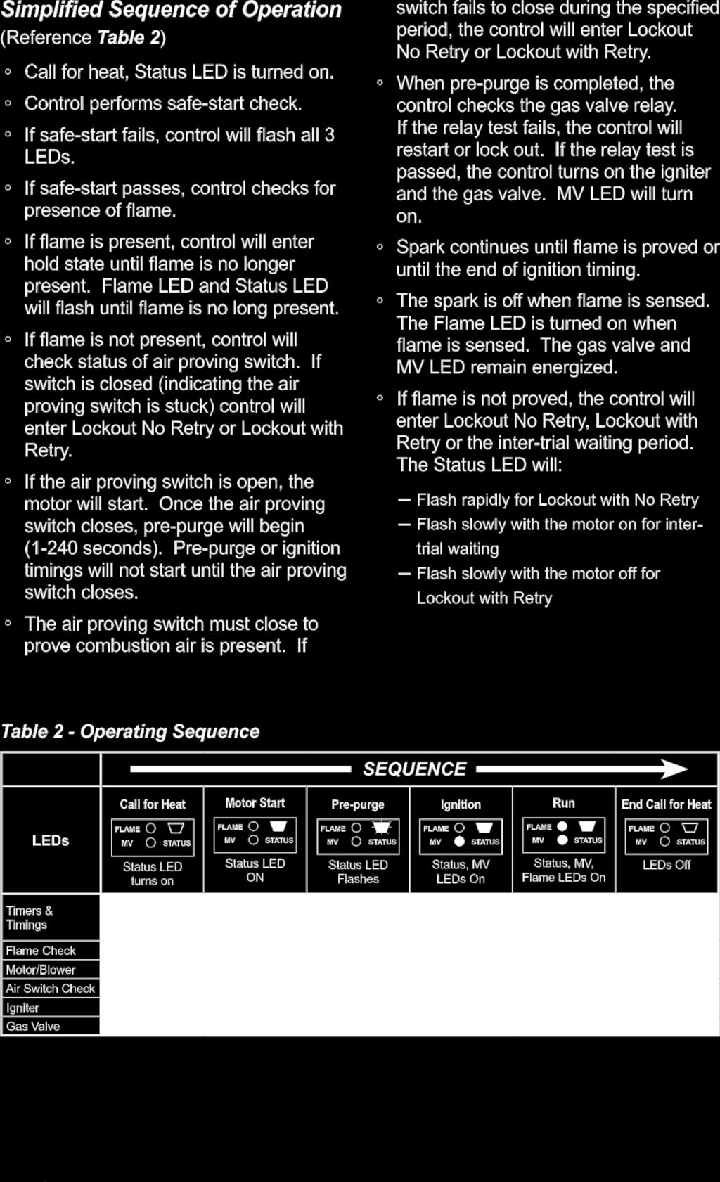
23 Sequence of Operation for Genisys Controller Burner States Standby: Valve-On Delay: Trial For Ignition: Lockout: The burner is idle, waiting for a call for heat. The igniter and motor are on while the control delays turning on the oil solenoid valve for 45 seconds.. The oil solenoid valve is energized. A flame should be established within the factory set trial for ignition time ("lockout time"). The control has shut down for one of the following safety reasons: a. The trial for ignition (lockout) time expired without flame being established. b. The cad cell detected flame at the end of the Valve On Delay state. To reset the control from lockout click the button 1-second. NOTE: A recurrence of the above failure modes or a failed welded relay check could cause the control to enter a Hard Lockout state that must be reset only by a qualified service technician. To reset from Hard Lockout, hold the reset button for 15 seconds until the yellow light turns on. Ignition Carryover: Run: Recycle: Motor-Off Delay: Pump Prime: Once flame is established, the igniter remains on to ensure flame stability. The flame is sustained until the call for heat is satisfied. The burner is then sent to Motor-Off Delay, if applicable, or it is shut down and sent to Standby. If the flame is lost while the burner is firing, the control shuts down the burner,enters a 60 second recycle delay, and repeats the ignition sequence. The control will continue to Recycle each time the flame is lost, until it reaches a pre-set time allotment. The control will then go into Hard Lockout instead of recycle. This feature prevents excessive accumulation of oil in the appliance firing chamber. If applicable, the oil solenoid valve is turned off and the control delays turning the motor off for the set motor-off delay time before the control returns to standby. The igniter and motor are on with the oil solenoid valve energized for 4 minutes. During Pump Prime mode, the cad cell is disregarded, allowing the technician to prime the pump without having to jumper the cad cell. 23
24 IDH200QR GAS BURNER PARTS Item Part # Description Item Part # Description 1 BG Cg4 HEAD/SHROUD ASSY 12 B /7 HP BURNER MOTOR 2 BG AIR TUBE ASSY FOR IDH BG GENISYS PRIMARY (GAS) 3 BG COVER PLATE 14 BG IGNITOR AND GASKET 4 BG GAS TRANSFORMER IDH 15 BG NAT GAS ORIFICE IDH200 5 BG AIR PROVING SWITCH 16 BG O RING 6 B20254 SHUTTER 17 BG ASSEMBLY, PIPE NIPPLE 7 BG AIR BAND 18 BG GAS VALVE 8 BG AIR BAFFLE 19 BG GAS GUN ASSY FG4 9 BG ELECTRICAL BOX 20 BG ELECTRODE/IGN LEAD 10 B20142 AIR GUIDE 21 BG NOZZLE FOR CG4 GAS 11 BG BLOWER WHEEL FOR CG4 22 BG FLAME ROD/WIRE ASSY 24
 OIL AND LP/NG AUTO RESET LIMIT FEELER FOR THE ABOVE HIGH LIMIT (21030) MANUAL HIGH LIMIT (LP/NG ONLY) 220 F (21005) LP/NG MANUAL RESET TEMP FEELER FOR THE ABOVE HIGH LIMIT")

25 LIMITS, FAN SWITCHES AND TEMPERATURE FEELERS ADJUSTABLE FAN SWITCH F (48111B) ALL MODELS FEELER ON FAN SWITCH IDH200QR OIL AND LP/NG (21029) IDH200QR AUTO HIGH LIMIT L190-40F (21006) OIL AND LP/NG AUTO RESET LIMIT FEELER FOR THE ABOVE HIGH LIMIT (21030) MANUAL HIGH LIMIT (LP/NG ONLY) 220 F (21005) LP/NG MANUAL RESET TEMP FEELER FOR THE ABOVE HIGH LIMIT (21031) Indoor and outdoor settings of fan switch Indoors & if surrounding air is warm i.e. -5C/23F-Fan switch should be set to 115 or higher so as to shut down unit when heat exchanger is properly cooled, also keeps fan motor from excessive running on when discharging cooler air. Outdoor-Fan switch should be set between The colder the temperature the lower the setting. 25
SPECIFICATIONS MODEL IDF350-II IDF500 IDF500HS 500,000 BTU/HR 2.5O USGPH 60 B (SOLID) 140 P.S.I. MAXIMUM 35 IMP GALS. 42 US GALS.
 140 P.S.I. MAXIMUM 35 IMP GALS. 42 US GALS.") SPECIFICATIONS MODEL IDF350-II IDF500 IDF500HS MAXIMUM INPUT 350,000 BTU/HR 500,000 BTU/HR 500,000 BTU/HR NOZZLE SIZE 2.00 USGPH 45 B (SOLID) 2.5O USGPH 60 B (SOLID) 2.5O USGPH 60 B (SOLID) PUMP PRESSURE
SPECIFICATIONS MODEL IDF350-II IDF500 IDF500HS MAXIMUM INPUT 350,000 BTU/HR 500,000 BTU/HR 500,000 BTU/HR NOZZLE SIZE 2.00 USGPH 45 B (SOLID) 2.5O USGPH 60 B (SOLID) 2.5O USGPH 60 B (SOLID) PUMP PRESSURE
INDIRECT FIRED SPACE HEATERS. Installation - Operation/Maintenance Instructions and Parts List
 FROST INDIRECT FIRED SPACE HEATERS MODEL OHV 200 MODEL OHV 350-II MODEL OHV 500 MODEL OHV 600 Installation - Operation/Maintenance Instructions and Parts List READ INSTRUCTIONS PRIOR TO STARTING HEATERS
INDIRECT FIRED SPACE HEATERS PROPANE AND NATURAL GAS. Installation - OperationMaintenance Instructions and Parts List
 FROST INDIRECT FI SPACE HEATERS PROPANE AND NATURAL GAS MODEL OHV 200LPNG MODEL IDF 350LPNG MODEL IDF 500LPNG MODEL IDF 500LP/NG HS Installation - OperationMaintenance Instructions and Parts List READ
OPERATING INSTRUCTIONS MANUAL (Please retain for future reference) FVO-200 INDIRECT FIRED SPACE HEATERS
 FVO-200 INDIRECT FIRED SPACE HEATERS") OPERATING INSTRUCTIONS MANUAL (Please retain for future reference) For FVO-200 INDIRECT FIRED SPACE HEATERS CERTIFIED FOR USE IN CANADA AND U.S.A. As per CSA B140.8 Portable Oil Fired Heaters / CSA B140.02003
OPERATING INSTRUCTIONS MANUAL (Please retain for future reference) For FVO-200 INDIRECT FIRED SPACE HEATERS CERTIFIED FOR USE IN CANADA AND U.S.A. As per CSA B140.8 Portable Oil Fired Heaters / CSA B140.02003
OPERATING INSTRUCTIONS MANUAL (Please retain for future reference) FVN/P-400 INDIRECT FIRED SPACE HEATERS
 FVN/P-400 INDIRECT FIRED SPACE HEATERS") OPERATING INSTRUCTIONS MANUAL (Please retain for future reference) For FVN/P-400 INDIRECT FIRED SPACE HEATERS CERTIFIED FOR USE IN CANADA AND U.S.A. As per Standard ANSI Z83.7/CSA 21.4 2000 Gas Fired Construction
OPERATING INSTRUCTIONS MANUAL (Please retain for future reference) For FVN/P-400 INDIRECT FIRED SPACE HEATERS CERTIFIED FOR USE IN CANADA AND U.S.A. As per Standard ANSI Z83.7/CSA 21.4 2000 Gas Fired Construction
OPERATING INSTRUCTIONS MANUAL (Please retain for future reference) FVO-200 INDIRECT FIRED SPACE HEATERS
 FVO-200 INDIRECT FIRED SPACE HEATERS") OPERATING INSTRUCTIONS MANUAL (Please retain for future reference) For FVO-200 INDIRECT FIRED SPACE HEATERS CERTIFIED FOR USE IN CANADA AND U.S.A. As per CSA B140.8 Portable Oil Fired Heaters / CSA B140.02003
OPERATING INSTRUCTIONS MANUAL (Please retain for future reference) For FVO-200 INDIRECT FIRED SPACE HEATERS CERTIFIED FOR USE IN CANADA AND U.S.A. As per CSA B140.8 Portable Oil Fired Heaters / CSA B140.02003
OPERATING INSTRUCTIONS MANUAL (Please retain for future reference) FVO-400 INDIRECT FIRED SPACE HEATERS
 FVO-400 INDIRECT FIRED SPACE HEATERS") OPERATING INSTRUCTIONS MANUAL (Please retain for future reference) For FVO-400 INDIRECT FIRED SPACE HEATERS CERTIFIED FOR USE IN CANADA AND U.S.A. As per CSA B140.8 Portable Oil Fired Heaters / CSA B140.02003
OPERATING INSTRUCTIONS MANUAL (Please retain for future reference) For FVO-400 INDIRECT FIRED SPACE HEATERS CERTIFIED FOR USE IN CANADA AND U.S.A. As per CSA B140.8 Portable Oil Fired Heaters / CSA B140.02003
OPERATING INSTRUCTIONS MANUAL (Please retain for future reference) F-1500T DUAL FUEL CONSTRUCTION HEATER
 F-1500T DUAL FUEL CONSTRUCTION HEATER") OPERATING INSTRUCTIONS MANUAL (Please retain for future reference) For F-1500T DUAL FUEL CONSTRUCTION HEATER CERTIFIED FOR USE IN CANADA AND U.S.A. As per Standard ANSI Z83.7 2000/ CSA 2.14 2000 Gas Fired
OPERATING INSTRUCTIONS MANUAL (Please retain for future reference) For F-1500T DUAL FUEL CONSTRUCTION HEATER CERTIFIED FOR USE IN CANADA AND U.S.A. As per Standard ANSI Z83.7 2000/ CSA 2.14 2000 Gas Fired
OPERATING INSTRUCTIONS MANUAL (Please retain for future reference) F-400T DUAL FUEL CONSTRUCTION HEATER
 F-400T DUAL FUEL CONSTRUCTION HEATER") OPERATING INSTRUCTIONS MANUAL (Please retain for future reference) For F-400T DUAL FUEL CONSTRUCTION HEATER CERTIFIED FOR USE IN CANADA AND U.S.A. As per Standard ANSI Z83.7 2000/ CSA 2.14 2000 Gas Fired
OPERATING INSTRUCTIONS MANUAL (Please retain for future reference) For F-400T DUAL FUEL CONSTRUCTION HEATER CERTIFIED FOR USE IN CANADA AND U.S.A. As per Standard ANSI Z83.7 2000/ CSA 2.14 2000 Gas Fired
OPERATING INSTRUCTIONS MANUAL (Please retain for future reference) F-1000T DUAL FUEL CONSTRUCTION HEATER
 F-1000T DUAL FUEL CONSTRUCTION HEATER") OPERATING INSTRUCTIONS MANUAL (Please retain for future reference) For F-1000T DUAL FUEL CONSTRUCTION HEATER CERTIFIED FOR USE IN CANADA AND U.S.A. As per Standard ANSI Z83.7 2000/ CSA 2.14 2000 Gas Fired
OPERATING INSTRUCTIONS MANUAL (Please retain for future reference) For F-1000T DUAL FUEL CONSTRUCTION HEATER CERTIFIED FOR USE IN CANADA AND U.S.A. As per Standard ANSI Z83.7 2000/ CSA 2.14 2000 Gas Fired
THC 85 / 175 INDUSTRIAL / COMMERCIAL SPACE HEATER
 THC 85 / 175 INDUSTRIAL / COMMERCIAL SPACE HEATER Certified to / Certifié à CGA 2.14 M2000 Conforms to / Conforme à ANSI std Z83.7 2000 Suitable for indoor or outdoor installation / Unvented / Unattended
OPERATING INSTRUCTIONS MANUAL (Please retain for future reference) FVN/P-400 INDIRECT FIRED SPACE HEATERS
 FVN/P-400 INDIRECT FIRED SPACE HEATERS") OPERATING INSTRUCTIONS MANUAL (Please retain for future reference) For FVN/P-400 INDIRECT FIRED SPACE HEATERS CERTIFIED FOR USE IN CANADA AND U.S.A. As per Standard ANSI Z83.7/CSA 21.4 2000 Gas Fired Construction
OPERATING INSTRUCTIONS MANUAL (Please retain for future reference) For FVN/P-400 INDIRECT FIRED SPACE HEATERS CERTIFIED FOR USE IN CANADA AND U.S.A. As per Standard ANSI Z83.7/CSA 21.4 2000 Gas Fired Construction
THC- 355DF (Dual Fuel)
") OPERATING INSTRUCTIONS MANUAL THC- 355DF (Dual Fuel) INDUSTRIAL / COMMERCIAL DIRECTIONAL SPACE HEATER (OPERATOR MUST RETAIN FOR FUTURE REFERENCES) Certified to / Certifié à ANSI std Z83.7 2000 Suitable
OPERATING INSTRUCTIONS MANUAL THC- 355DF (Dual Fuel) INDUSTRIAL / COMMERCIAL DIRECTIONAL SPACE HEATER (OPERATOR MUST RETAIN FOR FUTURE REFERENCES) Certified to / Certifié à ANSI std Z83.7 2000 Suitable
THC 85 INDUSTRIAL / COMMERCIAL SPACE HEATER
 A Division of THC 85 INDUSTRIAL / COMMERCIAL SPACE HEATER Certified to / Certifié à CGA 2.14 M2000 Conforms to / Conforme à ANSI std Z83.7 2000 Suitable for indoor or outdoor installation / Unvented /
THC-175DF INDUSTRIAL / COMMERCIAL SPACE HEATER. Certified to / Certifié à CGA 2.14 M2011 Conforms to / Conforme à ANSI std Z83.
 THC-175DF INDUSTRIAL / COMMERCIAL SPACE HEATER Certified to / Certifié à CGA 2.14 M2011 Conforms to / Conforme à ANSI std Z83.7 2011 Suitable for indoor or outdoor installation / Unvented / Unattended
THC 85N / 175N INDUSTRIAL / COMMERCIAL SPACE HEATER
 THC 85N / 175N INDUSTRIAL / COMMERCIAL SPACE HEATER Certified to / Certifié à CGA 2.14 M2000 Conforms to / Conforme à ANSI std Z83.7 2000 Suitable for indoor or outdoor installation / Unvented / Unattended
VF/VG700 Jumbo. Construction Heater. Installation and Maintenance Manual
 342 N. Co. Rd. 400 East Valparaiso, IN 46383 888-432-8924 Fax 219-462-7985 www.heatwagon.com Installation and Maintenance Manual Please retain this manual for future reference. VF/VG700 Jumbo Construction
OPERATING INSTRUCTIONS MANUAL (Please retain for future reference) FVN/P-400 INDIRECT FIRED SPACE HEATERS
 FVN/P-400 INDIRECT FIRED SPACE HEATERS") OPERATING INSTRUCTIONS MANUAL (Please retain for future reference) For FVN/P-400 INDIRECT FIRED SPACE HEATERS CERTIFIED FOR USE IN CANADA AND U.S.A. As per Standard ANSI Z83.7/CSA 21.4 2000 Gas Fired Construction
OPERATING INSTRUCTIONS MANUAL (Please retain for future reference) For FVN/P-400 INDIRECT FIRED SPACE HEATERS CERTIFIED FOR USE IN CANADA AND U.S.A. As per Standard ANSI Z83.7/CSA 21.4 2000 Gas Fired Construction
THC 85N / 175N INDUSTRIAL / COMMERCIAL SPACE HEATER
 THC 85N / 175N INDUSTRIAL / COMMERCIAL SPACE HEATER Certified to / Certifié à CGA 2.14 M2000 Conforms to / Conforme à ANSI std Z83.7 2000 Suitable for indoor or outdoor installation / Unvented / Unattended
1. GENERAL SAFETY RULES
 ID180 & ID290 Indirect-Fired Diesel/Oil Construction Heaters Sure Flame Products Lethbridge, Alberta, Canada Telephone: (403)328-5353 Fax: (403)328-9956 www.sureflame.ca July 12, 2006 Service and Maintenance
S150 S300 CONSTRUCTION HEATERS. Rev: August 15, 2008 SERVICE AND MAINTENANCE MANUAL No PLEASE RETAIN FOR FUTURE REFERENCE PRODUCTS
 S150 & S300 CONSTRUCTION HEATERS Rev: 2.7.2 August 15, 2008 SERVICE AND MAINTENANCE MANUAL No. 934-6637 PLEASE RETAIN FOR FUTURE REFERENCE PRODUCTS A DIVISION OF HAUL-ALL EQUIPMENT LTD. 4115-18 Avenue
CYLINDER NOT INCLUDED
 OPERATING INSTRUCTIONS AND OWNER S MANUAL Model # HS125NG / MH125LP / HS125LP READ INSTRUCTIONS CAREFULLY: Read and follow all instructions. Place instructions in a safe place for future reference. Do
DF400/DF600. Construction Heaters. Installation and Maintenance Manual
 342 N. Co. Rd. 400 East Valparaiso, IN 46383 219-464-8818 Fax 219-462-7985 www.heatwagon.com Installation and Maintenance Manual Please retain this manual for future reference. DF400/DF600 Construction
OPERATING INSTRUCTIONS MANUAL (Please retain for future reference) FVO-400 INDIRECT FIRED SPACE HEATERS
 FVO-400 INDIRECT FIRED SPACE HEATERS") OPERATING INSTRUCTIONS MANUAL (Please retain for future reference) For FVO-400 INDIRECT FIRED SPACE HEATERS CERTIFIED FOR USE IN CANADA AND U.S.A. As per CSA B140.8 Portable Oil Fired Heaters / CSA B140.02003
OPERATING INSTRUCTIONS MANUAL (Please retain for future reference) For FVO-400 INDIRECT FIRED SPACE HEATERS CERTIFIED FOR USE IN CANADA AND U.S.A. As per CSA B140.8 Portable Oil Fired Heaters / CSA B140.02003
INTRODUCTION THIS MANUAL INCLUDES IMPORTANT SAFETY INFORMATION
 INSTALLATION AND OPERATING INSTRUCTIONS FOR THE HARDY Fuel Oil Furnace Models D-140 & D-350 HARDY MANUFACTURING COMPANY, INC. 12345 ROAD 505 PHILADELPHIA, MS 39350 PHONE: (601) 656-5866 FAX: (601) 656-4559
P4000 Construction Heater
 342 N. Co. Rd. 400 East Valparaiso, IN 46383 219-464-8818 Fax 219-462-7985 www.heatwagon.com Installation and Maintenance Manual Please retain this manual for future reference. P4000 Construction Heater
Construction Heater. Installation and Maintenance Manual
 342 N. Co. Rd. 400 East Valparaiso, IN 46383 219-464-8818 Fax 219-462-7985 www.heatwagon.com Installation and Maintenance Manual Please retain this manual for future reference. 4200 Construction Heater
Installation and Maintenance Manual Please retain this manual for future reference.
 342 N. Co. Rd. 400 East Valparaiso, IN 46383 219-464-8818 Fax 219-462-7985 www.heatwagon.com Installation and Maintenance Manual Please retain this manual for future reference. 2000(L) Construction Heater
OPERATING INSTRUCTIONS MANUAL (Please retain for future reference) For FVO-400TRLT INDIRECT FIRED HEATER TRAILER
 For FVO-400TRLT INDIRECT FIRED HEATER TRAILER") OPERATING INSTRUCTIONS MANUAL (Please retain for future reference) For FVO-400TRLT INDIRECT FIRED HEATER TRAILER CERTIFIED FOR USE IN CANADA AND U.S.A. As per CSA B140.8 Portable Oil Fired Heaters / CSA
OPERATING INSTRUCTIONS MANUAL (Please retain for future reference) For FVO-400TRLT INDIRECT FIRED HEATER TRAILER CERTIFIED FOR USE IN CANADA AND U.S.A. As per CSA B140.8 Portable Oil Fired Heaters / CSA
1800(L) Construction Heater
 Construction Heater") 342 N. Co. Rd. 400 East Valparaiso, IN 46383 219-464-8818 Fax 219-462-7985 www.heatwagon.com Installation and Maintenance Manual Please retain this manual for future reference. 1800(L) Construction Heater
342 N. Co. Rd. 400 East Valparaiso, IN 46383 219-464-8818 Fax 219-462-7985 www.heatwagon.com Installation and Maintenance Manual Please retain this manual for future reference. 1800(L) Construction Heater
Internet Version for Reference Only INDUCED DRAFT COMMERCIAL WATER HEATERS SUPPLEMENT INSTRUCTIONS TO PART #
 INDUCED DRAFT COMMERCIAL WATER HEATERS SUPPLEMENT INSTRUCTIONS TO PART #238-39387-00 THIS INSTRUCTION SUPPLEMENT IS ONLY INTENDED TO GIVE INSTALLATION INSTRUCTIONS AND INFORMATION RELATED TO THE INDUCED
Columbia Boiler Company
 EMG Series Boilers Available in Natural Gas & Propane Rev 12012 Columbia Boiler Company PO Box 1070 Pottstown, PA 19464 Tel (610) 473-8457 Fax (610) 367-6800 Website www.columbiaboiler.com Email cbcsales@ptd.net
Installation and Maintenance Manual Please retain this manual for future reference.
 342 N. Co. Rd. 400 East Valparaiso, IN 46383 219-464-8818 Fax 219-462-7985 www.heatwagon.com Installation and Maintenance Manual Please retain this manual for future reference. DF400/DF600 Construction
OPERATING INSTRUCTIONS AND OWNER S MANUAL
 OPERATING INSTRUCTIONS AND OWNER S MANUAL MR. HEATER READ INSTRUCTIONS CAREFULLY: Read and follow all instructions. Place instructions in a safe place for future reference. Do not allow anyone who has
OPERATING INSTRUCTIONS MANUAL (Please retain for future reference)
") OPERATING INSTRUCTIONS MANUAL (Please retain for future reference) For FRHR-100N/P RADIANT CONSTRUCTION HEATERS CERTIFIED FOR USE IN CANADA AND U.S.A. As per Standard ANSI Z83.7 2000/ CSA 2.14 2000 Gas
OPERATING INSTRUCTIONS MANUAL (Please retain for future reference) For FRHR-100N/P RADIANT CONSTRUCTION HEATERS CERTIFIED FOR USE IN CANADA AND U.S.A. As per Standard ANSI Z83.7 2000/ CSA 2.14 2000 Gas
User s Manual & Operating Instructions Model Number MH-150NGT-GFA-A
 User s Manual & Operating Instructions Model Number MH-150NGT-GFA-A Factory ID: 001 DANGER Actual product features are subject to change due to ongoing improvements CONSUMER: READ AND SAVE THESE INSTRUCTIONS
Interrupted Ignition Series Oil Primary Control
 Interrupted Ignition Series Oil Primary Control Application Guide & Installation Instruction for ICM1511*, ICM1512*, ICM151*, ICM1514* For more information on our complete range of American-made products
OPERATING INSTRUCTIONS FORCED AIR PROPANE CONSTRUCTION HEATERS
 OPERATING INSTRUCTIONS FORCED AIR PROPANE CONSTRUCTION HEATERS Models 25,000-45,000 BTU/hr 30,000 BTU/hr 40,000 BTU/hr 50,000-85,000 BTU/hr 75,000-125,000 BTU/hr Type of Gas Gas Supply Pressure to Regulator
USER MANUAL SOM SERIES MUL-T-POISE WARM AIR OIL FIRED FURNACE
 USER MANUAL SOM SERIES MUL-T-POISE WARM AIR OIL FIRED FURNACE Save These Instructions For Reference ALL SOM SERIES FURNACES ARE AIR CONDITIONING READY! NOTICE TO HOMEOWNER THIS FURNACE SHALL BE INSTALLED
DOMESTIC WATER HEATER OIL FIRED
 DOMESTIC WATER HEATER OIL FIRED Models : CMO32-II CMO32-II-R CMO50-II CMO32-II & CMO32-II-R INSTALLER / SERVICE TECHNICIAN: USE THE INFORMATION IN THIS MANUAL FOR THE INSTALLATION AND SERVICING OF THE
SERVICE AND INSTALLATION MANUAL MODELS HDO(H) OIL FOR YOUR SAFETY
 OIL FOR YOUR SAFETY") Bousquet Technologies Inc. 2121, Nobel, Ste Julie, Quebec, Canada, J3E1Z9 SERVICE AND INSTALLATION MANUAL MODELS HDO(H) OIL Oil-Fired air heater for industrial and commercial use. FOR YOUR SAFETY Do not
Bousquet Technologies Inc. 2121, Nobel, Ste Julie, Quebec, Canada, J3E1Z9 SERVICE AND INSTALLATION MANUAL MODELS HDO(H) OIL Oil-Fired air heater for industrial and commercial use. FOR YOUR SAFETY Do not
PATRON CLIMAT OIL FIRED CONSTRUCTION HEATERS MODELS 40, 50 AND 130 OWNER S MANUAL. HEATER SIZES 135,000 and 195,000 and 570,000 BTU/Hr
 PATRON CLIMAT OIL FIRED CONSTRUCTION HEATERS MODELS 40, 50 AND 30 OWNER S MANUAL HEATER SIZES 35,000 and 95,000 and 570,000 BTU/Hr GENERAL HAZARD WARNING FAILURE TO COMPLY WITH THE PRECAUTIONS AND INSTRUCTIONS
SERVICE FACTS WARNING M801-SF-1C. Gas Furnaces Upflow & Downflow Induced Draft 1 Stage Heat Models: DISCONNECT POWER BEFORE SERVICING M801P040AU24AA
 SERVICE FACTS Gas Furnaces Upflow & Downflow Induced Draft Stage Heat Models: M80P00AU2AA M80P060AU2AA M80P060AU36AA M80P080BU36AA M80P080BU8AA M80P00BU36AA M80P00CU8AA M80P00CU60AA M80PDU60AA M80P0DU60AA
PARAFFIN/DIESEL HEATER
 PARAFFIN/DIESEL HEATER MODEL NO: XR60 PART NO: 6931002 OPERATION & MAINTENANCE INSTRUCTIONS LS0813 INTRODUCTION Thank you for purchasing this CLARKE product. Before attempting to use this product, please
DIESEL/PARAFFIN HEATERS
 DIESEL/PARAFFIN HEATERS MODEL NO: XR80, XR110, XR160, XR210 PART NO: 6931004, 6931006, 6931008, 6931012 OPERATION & MAINTENANCE INSTRUCTIONS LS0814 INTRODUCTION Thank you for purchasing this CLARKE product.
Burn Easy Installation Instructions LP or Natural Gas Fired Units. Cremator Setup:
 Burn Easy Installation Instructions LP or Natural Gas Fired Units Cremator Setup: 1. Place cremator, outdoor on a solid base consisting of concrete or gravel. Keep this site free of all vegetation. Combustibles
Bosch 80% AFUE Gas Furnace BGS80 Model
 Bosch 80% AFUE Gas Furnace BGS80 Model 4-Way Multipoise Category I Fan-Assisted Furnace User's Information Manual 3124627 2 Bosch 80% AFUE Gas Furnace User's Information Manual Data subject to change 06.2018
southbend A MIDDLEBY COMPANY INSTALLATION AND OPERATION MANUAL CG214 (E) CG314 (E) CG414 (E) CG220 (E) CG320 (E) CG325 (E) GAS BOILERS MODELS:
 CG314 (E) CG414 (E) CG220 (E) CG320 (E) CG325 (E) GAS BOILERS MODELS:") INSTALLATION AND OPERATION MANUAL GAS BOILERS MODELS: CG214 (E) CG314 (E) CG414 (E) CG220 (E) CG320 (E) CG325 (E) southbend A MIDDLEBY COMPANY 1100 Old Honeycutt Road Fuquay-Varina, NC 27526 (919) 552-9161
INSTALLATION AND OPERATION MANUAL GAS BOILERS MODELS: CG214 (E) CG314 (E) CG414 (E) CG220 (E) CG320 (E) CG325 (E) southbend A MIDDLEBY COMPANY 1100 Old Honeycutt Road Fuquay-Varina, NC 27526 (919) 552-9161
CMO32 CMO50 DOMESTIC WATER HEATER OIL-FIRED. Models: CMO32 CMO50
 DOMESTIC WATER HEATER OIL-FIRED Models: CMO32 CMO50 DNS-1102 Rev. A DNS-0413 Rev. A CMO32 CMO50 INSTALLER / SERVICE TECHNICIAN: USE THE INFORMATION IN THIS MANUAL FOR THE INSTALLATION AND SERVICING OF
USER S INFORMATION MANUAL
 USER S INFORMATION MANUAL UPFLOW/HORIZONTAL & DOWNFLOW TWO STAGE INDUCED DRAFT GAS FURNACES Recognize this symbol as an indication of Important Safety Information If the information in this manual is not
OPERATING INSTRUCTIONS SMO112 WARM AIR OIL FIRED FURNACE
 OPERATING INSTRUCTIONS SMO112 WARM AIR OIL FIRED FURNACE Save These Instructions For Reference SMO 112 FURNACES ARE AIR CONDITIONING READY! NOTICE TO HOMEOWNER THIS FURNACE SHALL BE INSTALLED BY A CERTIFIED
OPERATING INSTRUCTIONS MANUAL (Please retain for future reference) For FVO-1000TR INDIRECT FIRED HEATER TRAILER
 For FVO-1000TR INDIRECT FIRED HEATER TRAILER") OPERATING INSTRUCTIONS MANUAL (Please retain for future reference) For FVO-1000TR INDIRECT FIRED HEATER TRAILER CERTIFIED FOR USE IN CANADA AND U.S.A. As per CSA B140.8 Portable Oil Fired Heaters / CSA
OPERATING INSTRUCTIONS MANUAL (Please retain for future reference) For FVO-1000TR INDIRECT FIRED HEATER TRAILER CERTIFIED FOR USE IN CANADA AND U.S.A. As per CSA B140.8 Portable Oil Fired Heaters / CSA
Gold Oil Series. Model AF/AFG Burners for. High-efficiency Oil-fired Boilers. Instruction Manual
 Model AF/AFG Burners for Gold Oil Series High-efficiency Oil-fired Boilers Instruction Manual Type M Air Tube Combination Type L1 Head Type V1 Head Potential for Fire, Smoke and Asphyxiation Hazards Incorrect
PROPANE FORCED AIR. HEATER operation manual HL060F HL125F
 PROPANE FORCED AIR HEATER operation manual HL060F HL125F 2 table of contents Safety 6 Safety Rules 7 Safety Warnings Features 11 Features Assembly 12 Components 12 Assembling Frame and Wheels Operation
KEROSENE FORCED AIR HEATER
 KEROSENE FORCED AIR HEATER operation manual HK125RW HK300RW 2 table of contents Safety 6 Safety Rules 7 Safety Warnings Specifications 12 Specifications 13 Wiring Diagram Pre-Operation 14 General Instructions
OPERATING INSTRUCTIONS MANUAL FLE-150 INDUSTRIAL / COMMERCIAL ELECTRIC HEATER (OPERATOR MUST RETAIN FOR FUTURE REFERENCE)
") OPERATING INSTRUCTIONS MANUAL FLE-150 INDUSTRIAL / COMMERCIAL ELECTRIC HEATER (OPERATOR MUST RETAIN FOR FUTURE REFERENCE) Suitable for indoor or outdoor installation / Unvented / Unattended Type 26 Benfield
OPERATING INSTRUCTIONS MANUAL FLE-150 INDUSTRIAL / COMMERCIAL ELECTRIC HEATER (OPERATOR MUST RETAIN FOR FUTURE REFERENCE) Suitable for indoor or outdoor installation / Unvented / Unattended Type 26 Benfield
INSTALLATION AND OPERATION INSTRUCTIONS
 Printed in U.S.A. INSTALLATION AND OPERATION INSTRUCTIONS RFPA21A CONSTRUCTION HEATER FLOOR MODEL SAVE FOR FUTURE REFERENCE Space-Ray Division, Gas Fired Products, Inc. P.O. Box 36485, Charlotte, NC 28236
ZG Shown READ ALL INSTRUCTIONS IN THIS MANUAL AND RETAIN FOR FUTURE REFERENCE WARNING
 See unit nameplate for manufacturer and address. 507258-04 7/2018 Supersedes 10/2017 ZG 036, 048, 060, 072, 074 (3, 4, 5 and 6 Tons) ZG 092, 102, 120, 150 (7-1/2, 8-1/2, 10 and 12 Tons) ROOFTOP UNITS ZG
OPERATING INSTRUCTIONS MANUAL FLE-150 INDUSTRIAL / COMMERCIAL ELECTRIC HEATER (OPERATOR MUST RETAIN FOR FUTURE REFERENCE)
") OPERATING INSTRUCTIONS MANUAL FLE-150 INDUSTRIAL / COMMERCIAL ELECTRIC HEATER (OPERATOR MUST RETAIN FOR FUTURE REFERENCE) Suitable for indoor or outdoor installation / Unvented / Unattended Type 26 Benfield
OPERATING INSTRUCTIONS MANUAL FLE-150 INDUSTRIAL / COMMERCIAL ELECTRIC HEATER (OPERATOR MUST RETAIN FOR FUTURE REFERENCE) Suitable for indoor or outdoor installation / Unvented / Unattended Type 26 Benfield
100% Safety Shutoff Control 40,000 BTUH Input Rating Constant Pilot Propane Gas
 glor sun The Original Outdoor Patio Heater Manufactured by INFRARED DYNAMICS, INC. Yorba Linda, CA 92886 U.S.A. Tel: (714) 572-4050 Fax: (714) 572-6093 Toll-Free: (888) 317-5255 www.infradyne.com SPECIFICATIONS:
User s Manual & Operating Instructions Model Numbers MH-40-GFA / MH-60V-GFA-A / MH-125V-GFA-A / MH-150V-GFA-A
 User s Manual & Operating Instructions Model Numbers MH-40-GFA / MH-60V-GFA-A / MH-125V-GFA-A / MH-150V-GFA-A DANGER CONSUMER: READ AND SAVE THESE INSTRUCTIONS GENERAL HAZARD : FAILURE TO COMPLY WITH THE
USER MANUAL SLO / SFLO115 SERIES OIL FIRED WARM AIR FURNACES
 USER MANUAL SLO / SFLO115 SERIES OIL FIRED WARM AIR FURNACES Save These Instructions For Reference ALL SUMMERAIRE SLO115 / SFLO115 MODELS ARE AIR CONDITIONING READY! NOTICE TO HOMEOWNER THIS FURNACE SHALL
positions, side by side, end to end and Tee configurations. and utility pedestals
 The TOASTER Infrared Ground Thawing Equipment by Serious Thermal Products Ltd., is a propanefired, electrically operated infra-red ground thawing device specifically designed to remove frost from frozen
Corn Flame Energy Corn Stove Model 3000
 Corn Flame Energy Corn Stove Model 3000 Installation and Operation Guide Read thoroughly before starting installation Save this manual for future reference SAFETY NOTICE If this stove is not properly installed,
User s Manual & Operating Instructions Model Number MH-375T-GFA-A
 User s Manual & Operating Instructions Model Number MH-375T-GFA-A Factory ID: 001 DANGER Actual product features are subject to change due to ongoing improvements CONSUMER: READ AND SAVE THESE INSTRUCTIONS
PROPANE CONSTRUCTION HEATERS
 PROPANE CONSTRUCTION HEATERS OWNER S MANUAL 45 & 80 LP SIDE PV 0016 150 LP SIDE PV 017 Heater Sizes: 80,000 150,000 BTU/Hr IMPORTANT Read and understand this manual before assembling, starting, or servicing
Model No: Little Devil II (inc ss)
") GAS HEATER Model No: Little Devil II (inc ss) PART NO: 6926020, 6926025 (SS) OPERATION & MAINTENANCE INSTRUCTIONS LS1213 INTRODUCTION Thank you for purchasing this CLARKE Gas Heater. Before attempting
GAS HEATER Model No: Little Devil II (inc ss) PART NO: 6926020, 6926025 (SS) OPERATION & MAINTENANCE INSTRUCTIONS LS1213 INTRODUCTION Thank you for purchasing this CLARKE Gas Heater. Before attempting
Service Manual Model 3163
 Service Manual Model 3163 Contents Important Safety Information.......... 1 Specifications.................. 2 General Information.............. 2 Direct Vent Requirements........... 2 Propane System................
CYLINDER NOT INCLUDED
 OPERATING INSTRUCTIONS AND OWNER S MANUAL Model # MH35LP, HS35LP READ INSTRUCTIONS CAREFULLY: Read and follow all instructions. Place instructions in a safe place for future reference. Do not allow anyone
Model Universal Oil Primary Control
 Model 70200 Universal Oil Primary Control Installation and Operating Instructions For Use By Qualified Service Technicians Only Universal Replacement for Carlin, Beckett, Honeywell and ICM Controls On-Board
y Please read and carefully follow all instructions provided in this manual before installing, starting, or servicing this burner or heating system.
 Potential for Fire, Smoke and Asphyxiation Hazards Incorrect installation, adjustment, or misuse of this burner could result in death, severe personal injury, or substantial property damage. To the Homeowner
CINCINNATI, OH USA
 INSTRUCTION MANUAL Part No. 89731 Revised October 1997 CINCINNATI, OH 45241-4807 USA GAS SAFETY PRECAUTIONS Instructions on what to do when a user smells gas can be obtained from the local gas supplier.
WARNING. PROPANE FORCED AIR HEATER User s Manual & Operating Instructions. Safety Information
 Model Numbers MH-40-GFA / MH-60V-GFA-A / MH-125V-GFA-A / MH-150V-GFA-A MH-60V-GFA / MH-125V-GFA, MH-150V-GFA CONSUMER: READ AND SAVE THESE INSTRUCTIONS Safety Information GENERAL HAZARD : DANGER FAILURE
Using it in an enclosed space can kill you.
 38 X 56 GAS FIRE PIT - OWNER S MANUAL Carlisle Chat Fire Table Base Model # 00GBC7 (6877B) Fits 6877A Carlisle Chat Fire Table Top For Propane and *Natural Gas (*See Page 7) Certified to CSA International
WARNING. Keep area around vent terminal free of snow, ice, and debris.
 Information contained in this manual pertains to direct vent boilers equipped with manufacturer installed blocked vent safety control system (pressure switch).! WARNING Installations of venting shall be
V SERIES HDR GAS RANGES
 SERVICE MANUAL ONE POWERFUL PACKAGE V SERIES HDR GAS RANGES TOPS Open Top Hot Top Griddle Top Work Surface BASES Standard Oven Convection Oven Cabinet Base - NOTICE - This manual is prepared for use by
Fig. 1 - Unit PGD4, PGS4, WPG4
 OWNER S MANUAL 14 SEER Single -Package Air Conditioner and Gas Furnace System with R -410A Refrigerant Single Phase 2 to 5 Nominal Tons Three Phase 3 to 5 Nominal Tons PGD4andPGS4SeriesE,WPG4SeriesB Fig.
Installation Requirements for Models:
 900 & 9100 Series Refrigerators Installation Requirements for Models: 9162 9163 9182 9183 962 963 982 983 WARNING Improper installation, adjustment, alteration, service, or maintenance can cause injury
Installation, Operation and Service Manual
 Installation, Operation and Service Manual KLF-100 85% + EFFICIENCY OIL FIRED LOWBOY FURNACE INSTALLATIONS MUST MEET ALL LOCAL AND FEDERAL CODES THAT MAY DIFFER FROM THIS MANUAL Please read the manual
USER MANUAL OLM SERIES WARM AIR OIL FIRED FURNACE
 USER MANUAL OLM SERIES WARM AIR OIL FIRED FURNACE Save These Instructions For Reference ALL OLM SERIES FURNACES ARE AIR CONDITIONING READY! NOTICE TO HOMEOWNER THIS FURNACE SHALL BE INSTALLED BY A CERTIFIED
INSTALLATION AND OPERATION INSTRUCTIONS
 Printed in U.S.A. INSTALLATION AND OPERATION INSTRUCTIONS RCH100 CONSTRUCTION HEATER FLOOR MODEL WARNING IMPROPER INSTALLATION Improper installation, adjustment, alteration, service or maintenance can
PROPANE CONSTRUCTION HEATER
 PROPANE CONSTRUCTION HEATER OWNER S MANUAL Heater Size: 50,000 BTU/Hr IMPORTANT Read and understand this manual before assembling, starting, or servicing heater. Improper use of heater can cause serious
Owner s Information Manual
 48ES---A and 48VL---A Comfort and Performance 13 and 14 SEER Single Packaged Air Conditioner and Gas Furnace System With Puron (R---410A) Refrigerant Single and Three Phase 2---5 Nominal Tons (Sizes 24---60)
Owner s Manual. FMI BRANDS INC Avenue Surrey, B.C. Canada V3Z 3V7 Toll Free Fax Model number FMPPC2F
 Owner s Manual Model number FMPPC2F Series number 863 2017 FMI Brands Inc. Patent Pending D.863.000.V3 FMI BRANDS INC. 107 19052 26 Avenue Surrey, B.C. Canada V3Z 3V7 Toll Free 1-888-514-1663 Fax 1-888-797-9931
ECLIPSE INFORMATION GUIDE
 ECLIPSE INFORMATION GUIDE JUNIOR INDUSTRIAL BURNERS Models 0 & 6 JIB Info 80 0/9 Easy to install and operate. Rugged construction for long life in industrial environments. Protection against overheating
AFG AFG. Instruction Manual MODEL. Oil Burner. Types F & M air tubes Motor voltage: 120 Vac / 60 Hz. AFG burner with type F air tube
 MODEL AFG Oil Burner Instruction Manual AFG Types F & M air tubes Motor voltage: 120 Vac / 60 Hz AFG burner with type F air tube Type L1 head Type V1 head Type M air tube combinations Contents Prepare
40E ELECTRIC FAN HEATER
 40E ELECTRIC FAN HEATER PRODUCT MANUAL IMPORTANT READ AND UNDERSTAND THIS MANUAL BEFORE ASSEM- BLING, STARTING OR SERVICING THE HEATER. IMPROPER USE OF HEATER CAN CAUSE SERIOUS INJURY. KEEP THIS MANUAL
Owner s Guide Installation & Operation
 Owner s Guide Installation & Operation Hot Top HHT Series Hestan Commercial Corporation 3375 E. La Palma Ave Anaheim, CA 92806 (888) 905-7463 RETAIN THIS MANUAL FOR FUTURE REFERENCE P/N 002130 REV 1 IMPORTANT
55-Gallon Dispenser Package
 INSTRUCTIONS-PARTS LIST INSTRUCTIONS This manual contains important warnings and information. READ AND KEEP FOR REFERENCE. 308 666 Rev. A Husky 715 55-Gallon Dispenser Package 100 psi (6.9 bar) Maximum
OPERATING INSTRUCTIONS MANUAL FLE-60 INDUSTRIAL / COMMERCIAL ELECTRIC HEATER (OPERATOR MUST RETAIN FOR FUTURE REFERENCE)
") OPERATING INSTRUCTIONS MANUAL FLE-60 INDUSTRIAL / COMMERCIAL ELECTRIC HEATER (OPERATOR MUST RETAIN FOR FUTURE REFERENCE) Suitable for indoor or outdoor installation / Unvented / Unattended Type 26 Benfield
OPERATING INSTRUCTIONS MANUAL FLE-60 INDUSTRIAL / COMMERCIAL ELECTRIC HEATER (OPERATOR MUST RETAIN FOR FUTURE REFERENCE) Suitable for indoor or outdoor installation / Unvented / Unattended Type 26 Benfield
USER S INFORMATION MANUAL (2,4)SG13B
SG13B") USER S INFORMATION MANUAL (2,4)SG13B Series Gas Heating/Electric Cooling Package Unit Congratulations......your outdoor heating/cooling package unit is a valuable piece of equipment, designed and manufactured
USER S INFORMATION MANUAL (2,4)SG13B Series Gas Heating/Electric Cooling Package Unit Congratulations......your outdoor heating/cooling package unit is a valuable piece of equipment, designed and manufactured
Econo Heater. Waste Oil Fired Heater. Installation, operation and service instructions EH v Manual. Manufactured by
 Econo Heater Manufactured by Waste Oil Fired Heater Installation, operation and service instructions EH-75 120v Manual EconoHeat 5714 E. First Avenue Spokane Valley, WA 99212 800.255.1363 www.econoheat.com
Owner s Manual. FMI BRANDS INC th Avenue Surrey, B.C. Canada V3Z 3V7 Toll Free Fax Model number FMPPC2F
 Owner s Manual Model number FMPPC2F Series number 863 D.863.000.V0 FMI BRANDS INC. 309-19133 26th Avenue Surrey, B.C. Canada V3Z 3V7 Toll Free 1-888-514-1663 Fax 1-888-797-9931 Owner & Safety Manual Model
Owner s Guide Installation & Operation
 Owner s Guide Installation & Operation Char Broiler HCH Series Hestan Commercial Corporation 3375 E. La Palma Ave Anaheim, CA 92806 (888) 905-7463 RETAIN THIS MANUAL FOR FUTURE REFERENCE P/N 002134 REV
KG 092 SHOWN READ ALL INSTRUCTIONS IN THIS MANUAL AND RETAIN FOR FUTURE REFERENCE WARNING
 See unit nameplate for manufacturer and address. 507350-03 3/2016 Supersedes 9/2015 KG 024, 030, 036, 048, 060, 072, 074, 090 (2, 2-1/2, 3, 4, 5, 6 and 7-1/2 Tons) KG 092, 102, 120, 150 (7-1/2, 8 1/2,
Construction Heater GENERAL HAZARD WARNING
 Dayton Operating Operating Instructions Instructions & Parts and Parts Manual Manual Model Dayton Natural Gas Construction Heater Please read and save these instructions. Read carefully before attempting
B.C.S. Shop Heaters 26, 30 & 36 (36 shown)
") BIOMASS COMBUSTION SYSTEMS, INC. 67 MILLBROOK ST., SUITE 502 WORCESTER, MA 01606 508-798-5970 - FAX 508-798-5971 B.C.S. Shop Heaters 26, 30 & 36 (36 shown) INSTALLATION MANUAL HAND FIRED SYSTEMS 8-09 Biomass
BIOMASS COMBUSTION SYSTEMS, INC. 67 MILLBROOK ST., SUITE 502 WORCESTER, MA 01606 508-798-5970 - FAX 508-798-5971 B.C.S. Shop Heaters 26, 30 & 36 (36 shown) INSTALLATION MANUAL HAND FIRED SYSTEMS 8-09 Biomass
OVATION SERIES FIRE TABLES ASSEMBLY INSTRUCTIONS
 OVATION SERIES FIRE TABLES ASSEMBLY INSTRUCTIONS CSA Model98900 DRS02403 Installer: Leave these instructions with consumer. Consumer: Keep these instructions for future reference. DANGER If you smell gas:
SUPPLEMENTAL INSTRUCTIONS: DIRECT VENT INSTRUCTIONS FOR HIGH EFFICIENCY OIL-FIRED HOT WATER BOILER
 SUPPLEMENTAL INSTRUCTIONS: DIRECT VENT INSTRUCTIONS FOR HIGH EFFICIENCY OIL-FIRED HOT WATER BOILER Information contained in this manual pertains to direct vent boilers equipped with manufacturer installed