MILITARY TACTICAL HEATER 35,000 BTU SELF- POWERED, (MTH35SP)
|
|
|
- Bruce Manning
- 5 years ago
- Views:
Transcription


1 COMMERCIAL TECHNICAL MANUAL OPERATOR S, UNIT, AND DIRECT SUPPORT MAINTENANCE MANUAL MILITARY TACTICAL HEATER 35,000 BTU SELF- POWERED, (MTH35SP) REV 11JUN09
2 THIS PAGE INTENTIONALLY LEFT BLANK


3 WARNING SUMMARY This warning summary contains general safety warnings and hazardous materials warnings that must be understood and applied during operation of this equipment. Failure to observe these precautions could result in serious injury or death to personnel. Also included are explanations of safety and hazardous materials icons used within this technical manual. EXPLANATION OF SAFETY WARNING ICONS ELECTRICAL - electrical wire to arm with electricity symbol running through human body shows that shock hazard is present. HEAVY OBJECT human figure stooping over heavy object shows physical injury potential from improper lifting technique. CARBON MONOXIDE human figure showing gaseous substance being inhaled into respiratory system, demonstrating potential hazard. EXPLOSION - rapidly expanding symbol shows that the material may explode if subjected to high temperatures, sources of ignition, or high pressure. FIRE - flame shows that a material may ignite and cause burns. HOT AREA - hand over object radiating heat shows that part is hot and can burn. CRYOGENIC - hand in block of ice shows that the material is extremely cold and can injure human skin or tissue. CHEMICAL - drops of liquid on hand shows that the material will cause burns or irritation to human skin or tissue. POISON - skull and crossbones shows that a material is poisonous or is a danger to life. SHARP OBJECT - pointed object in hand shows that a sharp object presents a danger to limb. a Change 1
4 GENERAL SAFETY WARNINGS DESCRIPTION WARNING Carbon monoxide is without color or smell, but can kill you. Breathing carbon monoxide produces symptoms of headache, dizziness, loss of muscular control, a sleepy feeling, unconsciousness, or coma. Brain damage or death can result from heavy exposure. Carbon monoxide is present in the exhaust of any fuelburning heater and internal combustion engines. Dangerous levels of carbon monoxide will occur from operating the Space Heater, Convective in an enclosed area. Precautions must be followed to ensure operator s safety when the Space Heater, Convective is in operation. DO NOT operate Space Heater, Convective in an enclosed area. Direct the Space Heater, Convective exhaust outlet away from shelters or personnel. BE ALERT at all times during operating procedures for carbon monoxide poisoning. If symptoms are present, IMMEDIATELY evacuate personnel and seek medical attention. BE AWARE the field protection mask used for nuclear-biologicalchemical attack WILL NOT protect you from carbon monoxide poisoning. The best defense against Carbon Monoxide poisoning is good ventilation. WARNING Do not touch extremely cold metal parts with bare hands. Flesh may stick to extremely cold metal parts. Frostbite can cause permanent injury to personnel. WARNING Fuels are toxic and flammable. Do not refuel near open flame or other ignition sources. Only refuel in a well-ventilated area. Wear protective goggles, avoiding contact with skin and clothes, and don t breathe vapors. If contact with eyes or skin is made, immediately flush with clean water and get medical first aid for eyes immediately. Change 1 b
5 WARNING The Space Heater Convective weighs approximately 74 pounds (33.6 kg) without accessories. Two persons must carry the unit, lifting with your legs, not your back, to prevent injury. Failure to do so may result in serious back or other muscular skeletal injuries. WARNING Do not remove the heater assembly while any of the advisory lights are lit. Small, portable, shelter heaters of this type are not designed to be moved during operation or before purge cycles are complete. Serious injury, burns, or death can occur if the heater assembly is moved while operating or before the HEATER ON/ON-HOLD advisory light goes OFF indicating the end of operation, post purge, and cool down cycle completion. During operation some metal components of the heater assembly become extremely hot, such as the louver on the outlet duct, and the upper and lower heater housing assemblies. Contact with bare skin can cause severe burn injuries. During heater operation, air leaving the HEATED AIR OUTLET of the heater and passing through outlet duct with louver may exceed 220 F. Make sure tent personnel are aware of burn hazards and equipment hazards presented by the heated air and the louver. Do not attempt service procedures on a burner that has recently been in operation. Switch heater ON/OFF control to the OFF position, wait until the green HEATER ON/ON-HOLD light is OFF, and let the burner cool down before performing these procedures to avoid the possibility of serious burns. c Change 1
6 WARNING Gasoline, JP-4, mixed fuels, or solvents must not be used with the Space Heater, Convective under any circumstance. Only JP-8 or an approved alternate fuel as detailed in WP 0002 and WP 0001 Table 3 may be used. Failure to observe fuel requirements could cause damage to the heater assembly, fire danger-potential explosion, and injury or death to personnel within or around the tent and the heater assembly. Always place fuel can and stand in well-ventilated area as far away from open flames and other potential ignition sources as possible. Fuel spills shall be cleaned up in accordance with local requirements. Combustible material must be kept at least 2 feet away from the sides of the heater during operation. Always switch heater ON/OFF control to the OFF position and wait until the green HEATER ON/ON-HOLD light is OFF before refueling. WARNING Some metal components of SHC may have sharp edges. Wear gloves and use caution when handling and assembling the SHC to prevent cuts. Change 1 d
7 INSERT LATEST CHANGED PAGES / WORK PACKAGES. DESTROY SUPERSEDED DATA LIST OF EFFECTIVE PAGES / WORK PACKAGES NOTE: The portion of text affected by the changes is indicated by a vertical line in the outer margins of the page. Changes to illustrations are indicated by miniature pointing hands. Changes to wiring diagrams are Indicated by shaded areas. Original January 2002 Change June 2005 Dates of issue for original and changed pages / work packages are: TOTAL NUMBER OF PAGES FOR FRONT AND REAR MATTER ARE 36 AND TOTAL NUMBER OF WORK PACKAGES IS 70 CONSISTING OF THE FOLLOWING: Page / WP* No. Change No. Page / WP No. *Change No. Page / WP No. *Change No. Title 0 WP (2 pgs) 1 WP (4 pgs) 0 a-d (4 pgs) 1 WP (2 pgs) 1 WP (2 pgs) 0 A-B (2 pgs) 1 WP (2 pgs) 1 WP (4 pgs) 0 i-vi (6 pgs) 1 WP (2 pgs) 1 WP (4 pgs) 0 WP (6 pgs) 1 WP (4 pgs) 1 WP (4 pgs) 0 WP (10 pgs) 1 WP (2 pgs) 1 WP (2 pgs) 0 WP (4 pgs) 0 WP (2 pgs) 1 WP (2 pgs) 0 WP (12 pgs) 1 WP (2 pgs) 1 WP (2 pgs) 0 WP (26 pgs) 1 WP (2 pgs) 1 WP (2 pgs) 0 WP (14 pgs) 1 WP (2 pgs) 1 WP (2 pgs) 0 WP (6 pgs) 1 WP (4 pgs) 1 WP (2 pgs) 0 WP (2 pgs) 1 WP (4 pgs) 1 WP (2 pgs) 0 WP (12 pgs) 1 WP (2 pgs) 1 WP (2 pgs) 1 WP (10 pgs) 1 WP (4 pgs) 1 WP (2 pgs) 1 WP (20 pgs) 1 WP (18 pgs) 1 WP (2 pgs) 1 WP (2 pgs) 0 WP (16 pgs) 1 WP (4 pgs) 1 WP (4 pgs) 1 WP (10 pgs) 1 WP (2 pgs) 0 WP (2 pgs) 1 WP (2 pgs) 0 WP (2 pgs) 1 WP (2 pgs) 1 WP (2 pgs) 0 WP (2 pgs) 0 WP (2 pgs) 1 WP (4 pgs) 1 WP (4 pgs) 0 WP (2 pgs) 0 WP (2 pgs) 0 WP (2 pgs) 0 WP (2 pgs) 0 WP (6 pgs) 0 Glossary (2 pgs) 0 WP (4 pgs) 1 WP (8 pgs) 0 Index (8 pgs) 0 WP (2 pgs) 1 WP (2 pgs) 0 WP (8 pgs) 1 WP (2 pgs) 0 WP (4 pgs) 1 WP (2 pgs) 0 WP (2 pgs) 1 WP (2 pgs) 0 *Zero in this column indicates an original page or work package. A/(B Blank)
8
9 OPERATOR S AND UNIT MAINTENANCE MANUAL INCLUDING REPAIR PARTS AND SPECIAL TOOLS LIST FOR Military Tactical Heater 35K Self-Powered (MTH35SP) REPORTING ERRORS AND RECOMMENDING IMPROVEMENTS You can help improve this manual. If you find any mistakes or if you know of a way to improve the procedures, please let us know. Mail your letter together with DA Form 2028 (Recommended Changes to Publications and Blank Forms), located in the back of this manual, directly to: Commander, U.S. Army Tank-automotive and Armaments Command, ATTN: AMSTA-LC-CECT, Kansas Street, Natick, MA You may also send in your recommended changes via electronic mail directly to amssb-rim-e@natick-army.mil. A reply will be furnished to you. Instructions for sending an electronic 2028 may be found at the back of this manual immediately preceding the hard copy DISTRIBUTION STATEMENT A Approved for public release. Distribution is unlimited. WARNING SUMMARY HOW TO USE THIS MANUAL TABLE OF CONTENTS WP Sequence No. General Information CHAPTER 1 - DESCRIPTION AND THEORY OF OPERATION Location and Description of Major Components Theory of Operation CHAPTER 2 - OPERATOR INSTRUCTIONS Controls, Indicators, and Labels/Instruction Plates Preparation for Use Operation Under Usual Conditions Operation Under Unusual Conditions i
10 TABLE OF CONTENTS - Continued WP Sequence No. CHAPTER 3 TROUBLESHOOTING PROCEDURES Troubleshooting Malfunction Symptom Index Operator Troubleshooting Procedures Unit Troubleshooting Procedures CHAPTER 4 OPERATOR MAINTENANCE INSTRUCTIONS Operator Preventive Maintenance Checks and Services (PMCS) Operator Maintenance Procedures Flame Sensor Glow Plug CHAPTER 5 UNIT MAINTENANCE INSTRUCTIONS Unit Preventive Maintenance Checks and Services Unit Maintenance Procedures In tent Controller Assembly In tent Controller Assembly Cable Battery Pack Assembly Fuel Quick Disconnect Fuel Solenoid Valve and Sediment Strainer Fuel Hose Heater Control Assembly Wire Harness Power Control Assembly Ignition Pack Assembly Dust Cover Assembly Combustion Blower Assembly Combustion Blower Duct Assembly Combustion Air Inlet Assembly Upper Housing Assembly Exhaust Grommet Duct Adapters Heated Air Blower Assembly Fuel Pump Assembly Internal Fuel Lines Float Assembly Burner Assembly Thermoelectric Generator Heat Exchanger Lower Housing Assembly Return and Supply Ducts Preparation for Storage or Shipment CHAPTER 6 - SUPPORTING INFORMATION References Maintenance Allocation Chart (MAC) ii
11 TABLE OF CONTENTS - continued WP Sequence No. Repair Parts and Special Tools List (RPSTL) Introduction RPSTL Group 1 In-tent Controls RPSTL Group 2 Battery Pack Assembly RPSTL Group 3 External Fuel System Components RPSTL Group 4 Electronic Control System RPSTL Group 5 Chain And Dust Covers RPSTL Group 6 Combustion Blower Assembly RPSTL Group 7 Combustion Air Inlet RPSTL Group 8 Upper Housing Assembly RPSTL Group 9 Exhaust Grommet and O-ring RPSTL Group 10 Duct Adapters RPSTL Group 11 Heated Air Blower Assembly RPSTL Group 12 Internal Fuel System RPSTL Group 13 Burner Assembly RPSTL Group 14 Thermoelectric Generator RPSTL Group 15 Heat Exchanger RPSTL Group 17 Air Supply and Return Ducts SPECIAL TOOLS LIST National Stock Number (NSN) Index Part Number Index Components of End Item (COEI) List & Basic Issue Items (BII) List Additional Authorization List Expendable and Durable Items List Lubrication Instructions Torque Limits Mandatory Replacement Parts Glossary...Glossary-1 ALPHABETICAL INDEX... Index-1 iii/(iv Blank)
12
13 TM &P HOW TO USE THIS MANUAL This manual contains General Information, Operating Instructions, Operator Preventive Maintenance Checks and Services (PCMS), Troubleshooting, and Maintenance/Repair instructions for the MTH35SP Space Heater. Chapter 1 contains introductory information on the MTH35SP and its associated equipment as well as a Theory of Operation. Chapter 2 includes operating instructions under usual and unusual conditions. Chapter 3 contents include operator troubleshooting, PMCS, and service procedures. Chapter 4 contains Unit Maintenance instructions. Chapter 5 contains Direct Support Maintenance instructions. Chapter 6 contains references and other supporting information. Chapter 6 also includes the Repair Parts and Special Tools List (RPSTL) which identifies those parts or tools which are unique to the operation and maintenance of this equipment. Manual Organization and Page Numbering System. The manual is divided into six major chapters that detail the topics mentioned above. Within each chapter are work packages covering a wide range of topics. Each work package is numbered sequentially starting at page 1. The work package has its own page numbering scheme and is independent of the page numbering used by other work packages. Each page of a work package has a page number of the form XXXX YY-ZZ where XXXX is the work package number (e.g is work package 10) and YY is the revision number for that work package and ZZ represents the number of the page within that work package. A page number such as /2 blank means that page 1 contains information but page 2 of that work package has been intentionally left blank. Text and Illustrations. Descriptive text and procedures are always accompanied by one or more illustrations. The text or procedure will be annotated with find numbers such as (1) that correspond to a specific callout on the illustration. In this technical manual, the descriptive text or procedure will always precede the illustration. Therefore, when reading a section in the manual, always look for the accompanying illustration to follow the section. Finding Information. The Table of Contents permits the reader to find information in the manual quickly. The reader should start here first when looking for a specific topic. The Table of Contents lists the topics contained within each chapter and the Work Package Sequence Number where it can be found. Example: If the reader were looking for instructions on Preventive Maintenance Checks and Services, which is an Operator Maintenance topic, the Table of Contents indicates that Operator Maintenance information can be found in Chapter 4. Scanning down the listings for Chapter 4, Preventive Maintenance Checks and Services information can be found in WP (i.e. Work Package 10). An Alphabetical Index can be found at the back of the manual, and lists specific topics with the corresponding work package. v/(vi Blank)
14
15 MTH35SP GENERAL INFORMATION SCOPE Type of Manual. Operator s, Unit, and Direct Support Maintenance, including RPSTL. Part Number and Equipment Name. Part Number U.S. Army Modular Command Post System Space Heater, Convective. Purpose of Equipment. Heats a modular command post system (Tent) or other equivalent enclosure. MAINTENANCE FORMS, RECORDS, AND REPORTS Department of the Army forms and procedures used for equipment maintenance will be those prescribed by DA Pam , Functional Users Manual for The Army Maintenance Management System; DA Pam , Functional Users Manual for The Army Maintenance Management System - Aviation (TAMMS- A); or AR , Army Logistics Readiness and Sustainability. DESTRUCTION OF ARMY MATERIEL TO PREVENT ENEMY USE For destruction procedures for materiel, refer to TM PREPARATION FOR STORAGE OR SHIPMENT See unit maintenance instructions (WP ) for procedures that insure safe storage or shipment of the heater. NOMENCLATURE CROSS-REFERENCE LIST Shortened nomenclature is used in this manual to make procedures easier for you to read. A crossreference between the shortened nomenclature and the official nomenclature is shown in the following table. Manual Nomenclature Flange clamp Heater Mat Tent Official Nomenclature Clamp, V-Band with Nut U.S. Army Modular Command Post System Space Heater, Convective Mat, Petroleum Absorbent Modular Command Post System Change 1
16 REPORTING EQUIPMENT IMPROVEMENT RECOMMENDATIONS (EIR). If your heater needs improvement, let us know. Send us an EIR. You, the user, are the only one who can tell us what you don t like about your equipment. Let us know why you don t like the design or performance. Put it on an SF 368 (Product Quality Deficiency Report). Mail it to U.S. Army Tankautomotive & Armaments Command, ATTN: AMSTA-LC-CESS, Kansas Street, Natick, MA We will send you a reply. SAFETY, CARE, AND HANDLING General Safety While in operation, the heater presents a potential burn and carbon monoxide hazard. Proper precautions should be observed while operating the heater. Observe all warning and caution notes that appear before each maintenance operation. Refer also to the Warning Summary. Change
17 Handling WARNING The Space Heater Convective weighs approximately 74 pounds (33.6 kg) without accessories. Two persons must carry the unit, lifting with your legs, not your back, to prevent injury. Failure to do so may result in serious back or other muscular skeletal injuries. WARNING Do not remove the heater assembly while any of the advisory lights are lit. Small, portable, shelter heaters of this type are not designed to be moved during operation or before purge cycles are complete. Serious injury, burns, or death can occur if the heater assembly is moved while operating or before the HEATER ON/ON-HOLD advisory light goes OFF indicating the end of operation, post purge, and cool down cycle completion. During operation some metal components of the heater assembly become extremely hot, such as the grill on the outlet duct, the upper and lower heater housing assemblies, combustion exhaust pipe, etc., Contact with bare skin can cause severe burn injuries. During heater operation, air leaving the HEATED AIR OUTLET of the heater and passing through outlet duct with grill may exceed 220 F. Make sure tent personnel are aware of burn hazards and equipment hazards presented by the heated air and the grill. Combustible material must be kept at least 2 ft away from, the sides of the heater during operation. Do not attempt service procedures on a burner that has recently been in operation. Switch heater ON/OFF control to the OFF position, wait until the green HEATER ON/ON- HOLD light is OFF, and let the burner cool down before performing these procedures to avoid the possibility of serious burns. CORROSION PREVENTION AND CONTROL (CPC) Corrosion Prevention and Control of Army materiel is a continuing concern. It is important that any corrosion problems with this item be reported so that the problem can be corrected and improvements can be made to prevent the problem in future items Change 1
18 CORROSION PREVENTION AND CONTROL (CPC) Continued While corrosion is typically associated with rusting of metals, it can also include deterioration of other materials, such as rubber and plastic. Unusual cracking, softening, swelling, or breaking of the materials may be a corrosion problem. If a corrosion problem is identified, it can be reported using Standard Form 368, Product Quality Deficiency Report. Use of key words such as rust, deterioration, corrosion, or cracking will insure that the information is identified as a CPC problem. The form should be submitted to the address specified in DA Pam LIST OF ABBREVIATIONS/ACRONYMS AAL Additional Authorization List MAX Maximum AMP Ampere MCPS Modular Command Post System BII Basic Issue Item mm millimeter 0 C Degrees Celsius MSDS Material Safety Data Sheet CAGE Commercial And Government Entity MTOE Modified Table of Org and Equipment C Code CFM Cubic Feet per Minute MWO Modification Work Order cm Centimeter NBC Nuclear, Biological, Chemical COEI Component of End Item N-m Newton Meters CPC Corrosion Prevention Control PMCS Preventive Maintenance Checks and Services DC Direct Current POL Petroleum, Oil and Lubricant ea Each psi Pounds per square inch EIR Equipment Improvement QD Quick Disconnect Recommendation 0 F Degrees Fahrenheit Qty Quantity gal Gallons Ref Reference GFE Government Furnished Equipment Reqd Required hr Hour RPSTL Repair Parts and Special Tools List IAW In Accordance With SOP Standard Operating Procedure ID Inside Diameter TEG Thermoelectric Generator Illus Illustrated / Illustration TMDE Test, Measurement, Diagnostic Equipment in. Inches TOE Table of Organization and Equipment in.-lb Inch-pound U/I Unit of Issue k/pa Kilopascals U/M Unit of Measure Kg Kilogram UOC Usable On Code L liter V Volt lbs Pounds VDC Volt Direct Current lb-ft Pound-foot WP Work Package MAC Maintenance Allocation Chart Change
19 EQUIPMENT CHARACTERISTICS, CAPABILITIES, AND FEATURES The Modular Command Post System (MCPS), hereafter referred to as the tent, require a heat source. This heater fulfills the need for an independent, powerful, self-powered, self-sustaining, self-regulating, self-diagnostic heater. The heater is set up for operation outside the tent. The tent control assembly (with controls, visual advisory lights, and an audible alarm) must be mounted inside the tent and a control cable (remote) used to connect the tent control assembly to the heater. The operation of the heater is controlled by the ON-OFF switch, the LOWER-HIGHER control knob (both located on the control assembly), and the heater control assembly (located within the heater itself). Manual movement of the ON/OFF switch to the ON position will cause the heater to automatically execute a series of steps that lead to heater operation. Manual movement of the ON/OFF switch to the OFF position will cause the heater to automatically execute a safe and orderly shutdown. The status of the heater assembly can be determined by looking at the advisory lights on the tent control assembly or by listening to the audible alarm. These lights and the related audible alarm are controlled by the heater control assembly, which monitors the normal operation of heater, and, when an abnormal operating condition is detected, cause the heater to shut off. Also, when an abnormal operating condition is detected, the SYSTEM FAULT advisory light and the integral audible alarm are activated and pulse out the following SYSTEM FAULT diagnostic codes: Table 1. System Fault Diagnostic Codes. Number of Pulses System Fault and Audible Tones 1 LOW VOLTAGE 2 COMBUSTION BLOWER 3 LOSS OF FLAME 4 BURNER MAINTENANCE 5 GLOW PLUG 6 TEG OVER TEMPERATURE 7 OVER VOLTAGE 8 TIP-OVER 9 FIN TEMP SENSOR 10 TENT OVER TEMPERATURE 11 NOT USED 12 LOW SYSTEM VOLTAGE Change 1
20 JP-8 is the preferred fuel for all temperature conditions because it burns cleaner than other approved fuels and will provide the best heater performance, reducing the frequency of required burner maintenance. Use of diesel fuel will require regular burner cleaning every 250 operating hours. Alternate fuels are listed in Table 2 below. Table 2. Approved Fuels at Various Temperatures. Primary Fuel Ambient Temperature Specification JP-8 Above -60 F (-51.1 C) MIL-DTL-83133E Alternate Fuels Ambient Temperature Specification K-1 (Kerosene) Above -25 F (-31.7 C) DF-A Above -60 F (-51.1 C) A-A-52557A DF-1 Above -25 F (-31.7 C) A-A-52557A JP-5 Above -25 F (-31.7 C) MIL-DTL-5624U DF-2 Above +20 F (-6.7 C) A-A-52557A Change
21 CHAPTER 1 DESCRIPTION AND THEORY OF OPERATION SPACE HEATER, MTH35SP
22 THIS PAGE INTENTIONALLY LEFT BLANK
23 MTH35SP THEORY OF OPERATION The Space Heater, Convective (1) is installed outside the tent with its air supply (2) and return (3) ducts routed through passthrough sleeves (4) located in the side of the tent (5). A fuel can (6) mounted on a fuel can stand (7) feeds fuel to the space heater by means of a gravity feed adapter (8) and fuel hose (9). The fuel hose (9) is connected to the SHC by means of a quick disconnect connector (10). All SHC functions are controlled via the in-tent controller assembly (11) which hangs inside the tent. An in-tent controller assembly cable (12) is connected between the in-tent controller assembly and the heater in order to control all heater operations from inside the tent. An SHC operational cycle begins by switching the ON-OFF switch (13) on the in-tent controller assembly (11) to the ON position
24 MTH35SP THEORY OF OPERATION Placing the ON/OFF switch of the in-tent controller in the ON position sends a signal to the power control assembly (1) as well as to the heater control assembly (2) energizing the system. At this point the heater on/on-hold advisory light (3) on the in-tent controller illuminates indicating the heater has begun operation. A 12 volt battery pack assembly (4) is used to supply power to the heater control assembly (2) and power control assembly (1) and facilitates burner ignition until the thermoelectric generator (TEG) (5) begins generating power. The power drawn from the battery pack assembly is replaced by the TEG while the heater delivers heat to the shelter. Once power is applied to the system, the heater control assembly (2) sends a signal to the fuel solenoid valve assembly (6), opening the valve and allowing fuel to flow through the sediment strainer (7) to the float assembly (8). Fuel is then pumped in short pulsating bursts by the fuel pump (9) to the burner head assembly (10) where it is vaporized. The heater control assembly controls all electrical functions, including system startup, shutdown, and safety checks. It includes temperature and tilt sensors and the control circuit. The control circuit analyzes information from the sensors to maintain the optimum firing rate for the heater. To maintain the firing rate, it controls the rates of fuel and air flow, and continuously monitors the in-tent controller assembly settings to verify that the desired settings are reached. The control system also controls system startup and shutdown, and monitors the heater safety systems. If a fault is detected, it immediately begins the shutdown procedure and signals the operator that a fault has occurred. Once fuel enters the burner assembly (10), power is drawn from the battery pack (4), fed to the ignition pack (11), and applied to the glow plug (12) igniting the fuel. Cold air is drawn in through the combustion air inlet (13) and heated with the produced heat used to power the thermoelectric generator (5). The TEG converts heat into electricity which is used to recharge the battery pack. When the battery pack is charging, the battery charging advisory light (14) on the in-tent controller assembly illuminates. The heater continues to run as the battery pack recharges. When the battery pack (4) is fully recharged, the battery charged advisory light (15) on the in-tent controller assembly illuminates and the battery charging light (14) extinguishes. At this point, the heated air blower assembly (16) is engaged and cold air is drawn from the shelter through the breathable air inlet (17) and forced through the heat exchanger (18) at the outlet end of the heater. The shelter air is heated and forced out the air return duct (19) into the shelter as heated air. As heated air is supplied to the shelter, the temperature inside the shelter rises. This temperature is monitored by a sensor (20) on the in-tent controller assembly. When the shelter temperature reaches the value set on the lower/higher control (21) of the in-tent controller assembly, a signal is sent to the heater, and the burner assembly (10) is shut down. Air continues to circulate through the shelter via the heated air blower assembly (16) and the At Setpoint advisory light (22) illuminates. Once the temperature inside the shelter drops below the set point, the burner assembly (10) ignites and supplies more heated air to the shelter. Heater operation is terminated by switching the ON/OFF switch (23) on the in-tent controller to the OFF position. Power is no longer applied to the glow plug (12) and burner ignition terminated. The fuel solenoid valve (6) is closed and all fuel flow to the burner assembly (10) ceases. When all advisory lights are extinguished, the heater is shut down and can be moved or left in place for another operational cycle
25 MTH35SP THEORY OF OPERATION If a system fault occurs during operation, the heater control assembly (2) monitors this condition and sends a signal to the in-tent controller illuminating the System Fault advisory light (24) on the in-tent controller /(4 Blank)
26 THIS PAGE INTENTIONALLY LEFT BLANK
27 MTH35SP LOCATION AND DESCRIPTION OF MAJOR COMPONENTS The following are the major components of the Space Heater, Convective. A brief description of the function of each component and its location is detailed below. In-Tent Controller Assembly (1) The in-tent control assembly (1) contains the operator controls and advisory lights for the heater. The intent control assembly is a remotely wired, splash proof box that can be easily attached to the tent framework. The in-tent controller assembly is only intended for use inside the tent. In-Tent Controller Cable Assembly (2) An in-tent controller cable assembly (2) is used to connect the in-tent controller assembly to the heater. Battery Pack Assembly (3) The battery pack assembly consists of a 12-volt battery (3) with an electrical heating element. The battery pack assembly location is clearly marked and is located in a recess (4) below the lower housing assembly. Two fuse holders (5) carrying 20 amp fuses are incorporated into the side of the battery pack. Two spare fuses (6) are located at the breathable air inlet end of the heater. The battery is used for burner ignition, and to power the control system until the thermoelectric generator (TEG) generates power. The battery is recharged during heater operation by the TEG. Depending on battery condition and temperature, the battery has a approximate 30-minute recharge time. If battery temperatures are below 40 F (4.4 C), it is electrically heated by the heating element. When the battery reaches 60 F (15.6 C), the heating element is shut off by the controller. When battery heat is called for, only excess power is used for heating the tent. Combustion Air Inlet Assembly (7) The combustion air inlet assembly (7) is connected to the combustion air blower located inside the heater and is the source of outside air used for combustion by the burner assembly. Upper Housing Assembly (8) The upper housing assembly (8) consists of a compartment cover assembly having certain hardware and electrical wiring and connections mounted on it. Lower Housing Assembly (9) The frame and heater housing are welded together to form the lower housing assembly (9). Fuel Solenoid Valve Assembly (10) The fuel solenoid valve assembly (10) has a normally closed valve, which opens to allow fuel to enter the heater when the ON/OFF switch is in the ON position. The solenoid valve is closed when the switch is turned OFF or if heater control assembly detects a SYSTEM FAULT condition. This solenoid is independent of the fuel pump assembly described below. Fuel Quick Disconnect (11) A fuel quick disconnect (11) is located at the inlet side of the fuel solenoid valve assembly (10). This military style male fitting has a protective dust cap (12) chained to it for use when the heater is not connected to the fuel supply. Operating Instructions Plate Operating instructions plate (13) is provided on the in-tent control assembly (1) Change 1
 to prevent accidental entry of foreign objects into the heater assembly.")

 WARNING Do not touch the metal debris grill of the air return duct while the heater is running.")
 conducts heated (breathable) air from the heater assembly to tent. This duct is 10.")
28 LOCATION AND DESCRIPTION OF MAJOR COMPONENTS Continued Air Supply Duct with Debris Grill (14) The air supply duct with debris grill (14) conducts air from the tent to heater assembly for warming. This duct is 10.5 inches in diameter and has a debris grill (15) to prevent accidental entry of foreign objects into the heater assembly. A strap is used to connect the duct to the heater inlet. Note that upon initial shipment, the debris grill is not installed in the duct. The debris grill must be installed in the duct prior to using the heater IAW WP An airflow direction arrow tag (16) is permanently attached to the duct indicating that the flow of air moves from the debris grill end of the duct to the open end that connects to the heater. Air Return Duct with Debris Grill (17) WARNING Do not touch the metal debris grill of the air return duct while the heater is running. During heater operation the metal debris grill and the heated air coming from it can be as hot as 220 F (104 C). Touching the metal debris grill may result in serious burns. The air return duct with debris grill (17) conducts heated (breathable) air from the heater assembly to tent. This duct is 10.5 inches in diameter and has a debris grill (17) to prevent accidental entry of foreign objects into the heater assembly. A strap is used to connect the duct to the heater outlet duct adapter. Note that upon initial shipment, the debris grill is not installed in the duct. The debris grill must be installed in the duct prior to using the heater IAW WP An airflow direction arrow tag is permanently attached to the duct indicating that the flow of air moves from the open end that connects to the heater to the debris grill end of the duct that is installed in the tent duct tunnel. Accessory Bag (18) An accessory bag is provided to permit stowage of all loose Space Heater Convective items such as the air inlet and return ducts, in-tent controller assembly and cable, battery charger, gravity feed adapter, fuel hose, and fuel can stand Change


29 Change 1
30 Burner Assembly (1) The burner assembly (1) consists of a vaporization type burner. The burner assembly uses a glow plug (2) for starting and requires no power other than the combustion blower (3) and the fuel pump (4) to operate. During starting, an ignition pack (5) provides approximately 24 volts to the glow plug to improve cold weather performance. An external fuel drain (6) is also provided on the burner assembly to facilitate draining the fuel system. Heater Control Assembly (7) The heater control assembly (7) uses information from the heater s sensors and the tent control assembly to determine the ideal firing rate. The air/fuel ratio is adjusted as needed to maintain the ideal firing rate. The heater control assembly (7) is located on the inside lower housing opposite the battery compartment and is clearly marked. The heater control assembly controls all electrical functions, including system startup, shutdown, and safety checks. It includes temperature and tilt sensors and the control circuit. The control circuit analyzes information from the sensors to maintain the optimum firing rate for the heater. To maintain the firing rate, it controls the rates of fuel flow and air flow, and continuously monitors the in-tent control assembly settings to verify that the desired settings are reached. The control system also controls system startup and shutdown, and monitors the heater safety systems. If a fault is detected, it immediately begins the shutdown procedure and signals the operator that a fault has occurred. Combustion Air Blower (3) The combustion air blower assembly (3) integrates a 12-volt direct current (DC) combustion air fan (8). It is located in the lower heater housing directly below the control cable electrical connector and is clearly marked. The combustion air blower (3) draws air through the combustion air inlet (9) and passes it through flexible hoses (10) to the burner assembly (1). Heated Air Blower Assembly (11) A heated air blower assembly (11) is mounted under the duct adapter (12). It features a 12-volt DC fan in series at the inlet end of the heater. The fan moves approximately 250 cubic feet per minute (CFM) of heated, breathable air when operating. The heated air blower assembly (11) forces fresh air or air removed from the tent through the heater. This air passes across the TEG and the heat exchanger, where it absorbs heat and is directed into the tent. Change
31 Since the heater is designed to provide a variable British Thermal Units per hour (BTU/HR) output and still maintain internal generation of system and battery electricity, the heater needs to regulate between being a heater and being a generator of electricity as operational requirements change. This electronic marriage of components allows for a safe and smooth transition from generation of electricity to heating. The selection of a sophisticated controller reduces the amount of training required to operate the heater and provides continuous monitoring and control of the heater. Fuel Pump (4) The fuel pump (4) is controlled by frequency pulses from the heater control assembly and is responsible for supplying fuel in a vaporized state to the burner assembly. Heat Exchanger (13) The heat exchanger (13) transfers heat from hot gases produced by the burner to the heated (breathable) air. The heat exchanger is sandwiched between the upper housing assembly and the lower housing assembly. The heat exchanger provides an outlet and mounting flange for the combustion exhaust pipe (14) and an O-ring seal and gasket (15). This heated (breathable) air is then used to heat the tent. The heated air runs over the outside of the heat exchanger to collect the heat. The hot gases, or combustion fumes, inside the heat exchanger are exhausted outside the enclosure through the combustion exhaust pipe (14). Thermoelectric Generator (16) The thermoelectric generator (TEG) (16) provides heater system operating and battery recharging electrical power. Once the TEG is operating at full power, it supplies enough energy to operate the heater assembly and maintain a battery charging voltage of 14.5 volts. When the battery pack has been fully charged, the extra energy the TEG creates is converted into heat and used to heat the shelter. The TEG includes a mantle which directs the hot gases exiting the burner assembly to evenly heat the inside diameter (ID) of the TEG. This improves the ability of the TEG to generate electrical power. Power Control Assembly (17) The power control assembly is housed on a printed circuit board and mounted to the side wall of the lower housing assembly. The power control board manages the distribution of power throughout the Space Heater Convective Change 1
32 Change


33 ONBOARD SPARES AND TOOL. In addition to the foregoing major components, each space heater, convective package includes onboard spares and/or tools listed in Table 1. All the spares and tool are stored behind the duct adapter at the end of the heater labeled Breathable Air Inlet with the exception of the battery charging adapter. The battery charging adapter is stored in the Accessory Bag. Table 1. Onboard Spares and Tools. Item Name Qty Item Name Qty 1 Glow plug 1 5 Wrench 1 2 Flame sensor 1 6 Sediment Strainer Gasket 1 3* Battery charging adapter 1 7 Sediment Strainer Screen 1 4 Battery pack fuses 20 amp 2 * Battery charging adapter stored in accessory bag and 7 in bag under fan Change 1
34 ADDITIONAL EQUIPMENT REQUIRED FOR USE WITH THIS HEATER FUEL CAN. The 5 gallon (18.9 L) fuel can, listed on the AAL, provides a fuel source during heater operation. Table 2. Equipment Data. Manufacturer Hunter Manufacturing Company Part number Operating temperature range +65 F(+18.3 C) -60 F (-51.1 o C) BTU/Hr (automatically variable) Low 28,000 High 35,000 Efficiency 75-82% Electrical system volts DC Glow plug 11.5 volts DC (Starting only) Fuses, Spare Battery Pack 20 amp 2 each Battery Pack Fuses 20 Amp 2 each Combustion air fan 12 volt DC Rotron Revaflow Air flow Heated air (breathable) high fire rate 250 CFM Heated air temperature rise 140 F (60 C) Maximum at duct debris grill 240 F (115 C) Combustion air outlet temperature (exhaust) F ( C) Heater dimensions (without accessories) Length inches (102,87 cm) Width inches (36,19 cm) Height inches (46,66 cm) Heater volume cubic feet (0,1756 m 3 ) Heater weight (without accessories) 74 pounds Fuel requirements: Primary Fuel: Above -60 F (-51.1 C) MIL-DTL-83133E (JP-8) Alternate Fuels Above -25 F (-31.7 C) Kerosene (K-1) Above -60 F (-51.1 C) A-A-52557A (DF-A) Above -25 F (-31.7 C) A-A-52557A (DF-1) Above -25 F (31.7 C) MIL-DTL-5624U (JP-5) Above +20 F (-6.7 C) A-A-52557A (DF-2) Fuel consumption 2 hours/gal. (maximum) 3.5 hours/gal. (average) Change
35 Table 2. Equipment Data - Continued. Minimum safe distance to combustibles Battery pack (with heater) Type Rating Burner assembly Glow plug All other electrical components Manufacturer Battery Pack Thermoelectric generator (TEG) Manufacturer Type Rating 2 feet Starved electrolyte (gel cell) volts volts Gates 1 each Global Lead telluride (vacuum sealed) 180 watts, 15 amps /(10 Blank) Change 1
36
37 MTH35SP THEORY OF OPERATION The Space Heater, MTH35SP (1) is installed outside the tent with its air supply (2) and return (3) ducts routed through passthrough sleeves (4) located in the side of the tent (5). A fuel can (6) mounted on a fuel can stand (7) feeds fuel to the space heater by means of a gravity feed adapter (8) and fuel hose (9). The fuel hose (9) is connected to the MTH35SP by means of a quick disconnect connector (10). All MTH35SP functions are controlled via the in-tent controller assembly (11) which hangs inside the tent. An in-tent controller assembly cable (12) is connected between the in-tent controller assembly and the heater in order to control all heater operations from inside the tent. An MTH35SP operational cycle begins by switching the ON-OFF switch (13) on the in-tent controller assembly (11) to the ON position
38 MTH35SP THEORY OF OPERATION Placing the ON/OFF switch of the in-tent controller in the ON position sends a signal to the power control assembly (1) as well as to the heater control assembly (2) energizing the system. At this point the heater on/on-hold advisory light (3) on the in-tent controller illuminates indicating the heater has begun operation. A 12 volt battery pack assembly (4) is used to supply power to the heater control assembly (2) and power control assembly (1) and facilitates burner ignition until the thermoelectric generator (TEG) (5) begins generating power. The power drawn from the battery pack assembly is replaced by the TEG while the heater delivers heat to the shelter. Once power is applied to the system, the heater control assembly (2) sends a signal to the fuel solenoid valve assembly (6), opening the valve and allowing fuel to flow through the sediment strainer (7) to the float assembly (8). Fuel is then pumped in short pulsating bursts by the fuel pump (9) to the burner head assembly (10) where it is vaporized. The heater control assembly controls all electrical functions, including system startup, shutdown, and safety checks. It includes temperature and tilt sensors and the control circuit. The control circuit analyzes information from the sensors to maintain the optimum firing rate for the heater. To maintain the firing rate, it controls the rates of fuel and air flow, and continuously monitors the in-tent controller assembly settings to verify that the desired settings are reached. The control system also controls system startup and shutdown, and monitors the heater safety systems. If a fault is detected, it immediately begins the shutdown procedure and signals the operator that a fault has occurred. Once fuel enters the burner assembly (10), power is drawn from the battery pack (4), fed to the ignition pack (11), and applied to the glow plug (12) igniting the fuel. Cold air is drawn in through the combustion air inlet (13) and heated with the produced heat used to power the thermoelectric generator (5). The TEG converts heat into electricity which is used to recharge the battery pack. When the battery pack is charging, the battery charging advisory light (14) on the in-tent controller assembly illuminates. The heater continues to run as the battery pack recharges. When the battery pack (4) is fully recharged, the battery charged advisory light (15) on the in-tent controller assembly illuminates and the battery charging light (14) extinguishes. At this point, the heated air blower assembly (16) is engaged and cold air is drawn from the shelter through the breathable air inlet (17) and forced through the heat exchanger (18) at the outlet end of the heater. The shelter air is heated and forced out the air return duct (19) into the shelter as heated air. As heated air is supplied to the shelter, the temperature inside the shelter rises. This temperature is monitored by a sensor (20) on the in-tent controller assembly. When the shelter temperature reaches the value set on the lower/higher control (21) of the in-tent controller assembly, a signal is sent to the heater, and the burner assembly (10) is shut down. Air continues to circulate through the shelter via the heated air blower assembly (16) and the At Setpoint advisory light (22) illuminates. Once the temperature inside the shelter drops below the set point, the burner assembly (10) ignites and supplies more heated air to the shelter. Heater operation is terminated by switching the ON/OFF switch (23) on the in-tent controller to the OFF position. Power is no longer applied to the glow plug (12) and burner ignition terminated. The fuel solenoid valve (6) is closed and all fuel flow to the burner assembly (10) ceases. When all advisory lights are extinguished, the heater is shut down and can be moved or left in place for another operational cycle
39 MTH35SP THEORY OF OPERATION If a system fault occurs during operation, the heater control assembly (2) monitors this condition and sends a signal to the in-tent controller illuminating the System Fault advisory light (24) on the in-tent controller /(4 Blank)
40 THIS PAGE INTENTIONALLY LEFT BLANK
41 CHAPTER 2 OPERATOR INSTRUCTIONS SPACE HEATER, MTH53SP
42 THIS PAGE INTENTIONALLY LEFT BLANK

43 MTH35SP CONTROLS, INDICATORS, AND LABELS/INSTRUCTION PLATES GENERAL This section contains information on the controls, indicators, and label/instruction plates located on the MTH35SP. Before operating the heater, the user should become familiar with the controls and indicators provided on the unit. The operating controls are installed on the in-tent control assembly (1) and on the lower housing assembly (2). 1 2 HEATER CONTROLS AND INDICATORS The description and function of the controls and indicators of the in-tent controller assembly are detailed in Table 1. The manual reset thermostat located on the lower housing assembly is described in Table 2. Table 1. In-Tent Control Assembly Controls and Indicators Key Name Function 1 ON-OFF switch Controls starting and stopping of the heater. Movement of the ON/OFF switch from one position to another initiates the step-bystep transition of the heater from one operating condition to another (the OFF condition to the ON condition, or the ON condition to the OFF condition). This step-by-step transition is controlled and timed by the heater control assembly, and not by the movement of the ON/OFF switch. 2 HEATER ON/ON-HOLD light (green) 3 LOWER/HIGHER control knob When lit, indicates the heater assembly is in one of the following modes: 1) pre-purge, 2) normal operation, 3) on-hold. The onhold mode means that the heater is not operating but it is ready to start in response to changes in the tent temperature or changes to the LOWER-HIGHER control settings. Controls the setpoint that the heater is trying to reach, thereby controlling the heat output of the heater. Adjusting the control knob causes the heater assembly to provide higher or lower heat
44 MTH35SP CONTROLS, INDICATORS, AND LABELS/INSTRUCTION PLATES Table 1. In-Tent Control Assembly Controls and Indicators Key Name Function outputs to the tent. When the temperature within the tent reaches the setpoint, an amber AT SETPOINT light glows. When the temperature sensor registers this temperature, the heater begins to regulate its output so that the temperature is maintained. 4 BATTERY CHARGING light (green) 5 BATTERY CHARGED light (green) When lit, indicates the heater assembly battery is being charged by the TEG. While this light is lit, the heater s electronic controller does not allow the heater to respond to the LOWER-HIGHER control knob settings unless all the electrical requirements of heater operation and battery charging are met. When lit, indicates the heater assembly battery is fully charged and the heater will respond fully to the changes in tent temperature or changes to the LOWER-HIGHER control knob settings. Once this light comes on, the heater can be turned off with assurance that the battery is fully charged and there will be enough power for the next startup. 6 SYSTEM FAULT light (red) When this advisory light is pulsing and the related audible alarm (also located within the tent control assembly) is buzzing, it indicates the heater assembly sensors and the electronic heater control assembly have detected an unsafe operating condition and the heater has begun to shut itself off. This advisory light and audible alarm provide a sequence of from I to 10 pulses that correspond to diagnostic codes explaining the cause of SYSTEM FAULT. See back of the heater control assembly for diagnostic codes. 7 AT SETPOINT light (amber) When lit, indicates the interior tent temperature is at or above the LOWER-HIGHER control setting
45 MTH35SP CONTROLS, INDICATORS, AND LABELS/INSTRUCTION PLATES
46 MTH35SP CONTROLS, INDICATORS, AND LABELS/INSTRUCTION PLATES Table 2. Lower Housing Assembly Controls and Indicators Key Name Function 8 Manual Reset Thermostat A manual reset thermostat comprising a high-temperature cutout with a built-in reset switch is located on the lower portion of the heater housing. Its purpose is to backup the temperature sensors of the heater control system. In a situation where the heat exchanger overheated and the heater controller did not shut down the heater, this manual reset thermostat would activate and cut off all electrical power to the heater, thus causing the heater to shut down; Once the heater is determined to be safe for operation, the manual reset thermostat must be reset by pushing the reset switch button located underneath the rubber protector that is located on the heat exchanger end of the heater
47 MTH35SP CONTROLS, INDICATORS, AND LABELS/INSTRUCTION PLATES LABELS AND INSTRUCTION PLATES Table 3 illustrates the decals and information plates affixed to the heater assembly as well as the location of each decal or plate on the heater assembly. Table 3. SHC Labels and Instruction Plates Label or Instruction Plate Location Code
48 MTH35SP CONTROLS, INDICATORS, AND LABELS/INSTRUCTION PLATES Table 3. SHC Labels and Instruction Plates Label or Instruction Plate Location Code
49 MTH35SP CONTROLS, INDICATORS, AND LABELS/INSTRUCTION PLATES Table 3. SHC Labels and Instruction Plates Label or Instruction Plate Location Code TO START: CONNECT DIESEL FUEL AND NECESSARY DUCT WORK TO HEATER, THEN POSITION ON/OFF SWITCH TO THE ON POSITION. HEATER IS OPERATING WHEN ONE OR MORE GREEN ADVISORY LIGHTS ARE ON ON OFF TO STOP: POSITION ON/OFF SWITCH TO OFF POSITION. HEATER IS SAFE FOR REFUELING OR RELOCATING AFTER ALL ADVISORY LIGHTS ARE OFF. HEATER ON / ON - HOLD 1 LOWER 5 HIGHER BATTERY CHARGING BATTERY CHARGED SYSTEM FAULT AT SETPOINT
50 MTH35SP CONTROLS, INDICATORS, AND LABELS/INSTRUCTION PLATES Top View of Heater Side View of Heater (Battery Side) Side View of Heater (Fuel Inlet Side)
51 MTH35SP CONTROLS, INDICATORS, AND LABELS/INSTRUCTION PLATES /(10 Blank)
52 THIS PAGE INTENTIONALLY LEFT BLANK
53 MTH35SP OPERATION UNDER USUAL CONDITIONS PREPARATION FOR USE Unpacking and Inspection Upon Receipt. Inspect containers and packaging upon receipt for evidence of damage occurring in shipping. The heater package and its accessories were carefully inspected and securely packaged prior to shipment. If damage to the containers or packaging is found it is the shipper s responsibility. Do not unpack a heater that is obviously damaged in shipment until the shipper is notified and has inspected the packaging. Notify your supervisor. Remove heater package and accessories from shipping containers and packaging. Inspect the heater package and accessories for completeness by comparing the contents against the description of the equipment found in the Components of End Item work package of this technical manual. NOTE Heater will not operate when tilt or grade is greater than 15 degrees, which is a 1.5-foot drop over a 10-foot span. MTH35SP TENT WALL MODIFICATION KIT (TWMK) INSTALLATION In order to operate the MTH35SP with the Command Post Shelter, tent duct tunnels must be present on one of the walls of the tent. The installation of the tent duct tunnels must be performed before using the MTH35SP. If these tunnels are not present on the shelter, the tent wall modification kit (NSN , Part Number , CAGEC 92878) must be applied to the tent. Complete instructions for the installation of the tent wall modification are contained in the following section. Tools Required: Cutting Tool (knife or razor blade). Marking Tool (pen, pencil, or marker). Philips Screwdriver. Punch (if available). Components included with kit: 4 retaining rings [2 Cuff Rings (with fabric attached) and 2 Plain Rings]. 9 bolts & 9 nuts Change 1

, enter the tent and lift up the tent liner (if present)")

54 Cuff Ring Plain Ring Bolt & Nuts Determine location to install TWMK NOTE The entire assembly process can be done from inside the tent. 1. To determine the proper location for the installation of the Tent Wall Modification Kit (TWMK), enter the tent and lift up the tent liner (if present) to expose tent wall. 2. Measure approx. 3 ¼ feet from the center of the tent towards a side wall. 3. Measure approx. 12 inches up from the floor and mark an X. Change


55 ft 12 inches 4. Repeat step 2 & 3 for other side. 5. The distance between the two marked X s should be approx. 6 ½ feet. 6. Place a plain ring around the marked X on one side, (center X inside Plain Ring). 7. Using a punch or a Philips screwdriver, punch a hole through the top hole of the Plain Ring thru the tent material. 8. Place a bolt through that hole to temporarily hold the plain ring in place onto the tent. 9. Continue to punch holes for the remaining five holes as you put in a bolt in each punched hole. (It s important that you put in a bolt after each punched hole to maintain alignment). 10. Once all bolts are in place, using the plain ring as a template, cut out a hole in the tent wall along the inside diameter of the ring (approximately 19 diameter hole) Change 1


56 Repeat steps 6 thru 10 for the other hole location. 12. Once the large holes have been cut out, remove the plain rings and hardware from the wall. 13. Install a cuff ring where the plain ring was previously located on the inside tent wall with the fabric cuff pushed through to the outside of the tent. 14. Line up and install the bolts through the cuff ring and the tent wall. Use the Philips screwdriver to help in screwing the bolts through the fabric to the outside. 15. Squeeze and push the plain ring through the cuff ring to the outside. Change
 on the protruding bolts outside of tent so as to sandwich the tent wall between the 2 rings. 18.")
57 Line up the plain ring with the protruding bolts. 17. Place and tighten the nuts (9 total) on the protruding bolts outside of tent so as to sandwich the tent wall between the 2 rings. 18. Repeat steps 13 thru 17 for the other hole location. NOTE A successful completion should look comparable to the photo below Change 1
58 SITE SELECTION CRITERIA (OUTSIDE THE TENT) WARNING The MTH35SP weighs approximately 74 pounds (33.6 kg) without accessories. Two persons must carry the unit, lifting with your legs, not your back, to prevent injury. Failure to do so may result in serious back or other muscular skeletal injuries. WARNING Small, portable, shelter heaters of this type are not designed to be moved during operation or before purge cycles are complete. Serious burn injury or death can occur if the heater assembly is moved while operating or before the HEATER ON/ON-HOLD advisory light goes OFF indicating the end of operation, post purge, and cool down cycle completion. The MTH35SP site will be dictated by the location of the tent since the heater inlet (1) and outlet (2) ducts must be able to reach the tent duct tunnels (3). NOTE Heater will not operate when tilt or grade is greater than 15 degrees, which is a 1.5-foot drop over a 10-foot span. The heater site must be as level as possible (heater will not start or operate if the slope is greater than 15 degrees), and free of combustible material (e.g. dried twigs, leaves. etc.). If snow is present, it should be removed from the area immediately beneath and around the heater. The site should be selected so that the heater will be positioned at least 2 feet (61 cm) from combustibles, including the tent wall. Change
59 BEFORE OPERATION PMCS Perform the Before Operation PMCS on all SHC system components as outlined in WP 0010, prior to preparing the heater for use. All scheduled maintenance must be performed on the heater and its associated equipment prior to use Change 1
 so that the combustion exhaust outlet (4) is directed away from the tent wall (2) and the two supplied five foot (152 cm) long ducts (5) can be connected to both the heater")
60 Positioning the Heater Outside Tent. Place heater on the side of the tent that has the tent duct tunnels (1). The heater should be a minimum of 2 feet (61 cm) from tent walls (2). Position the heater (3) so that the combustion exhaust outlet (4) is directed away from the tent wall (2) and the two supplied five foot (152 cm) long ducts (5) can be connected to both the heater (3) and the tent (2). Do not install the ducts or connect the fuel supply at this time, simply place the heater in position Feet Minimum 4 5 PREPARING A FUEL SUPPLY SITE Select a fuel supply site that is level, free of debris and open flame, at least seven feet (2.13 meters) from the tent, and a minimum of five feet from heater. Change
61 NOTE A piece of petroleum absorbent material should be placed where the fuel can and fuel can stand will be installed as well as under the fuel quick disconnect connector in order to catch any fuel that may spill. Additional commercial products are available to contain large spills. Soiled absorbent material should be discarded in accordance with local environmental regulations. Route the fuel supply hose from the heater to the fuel supply location to gauge where the fuel supply site is best located. Place a petroleum absorbent mat where the fuel can stand will be set up. FILL FUEL CAN WITH FUEL AND INSTALL FUEL CAN ADAPTER Heater Assembly Fuel Selection WARNING Gasoline, JP-4, mixed fuels, or solvents must not be used with the MTH35SP under any circumstance. Only JP-8 or an approved alternate fuel as detailed in WP and WP Table 3 may be used. Failure to observe fuel requirements could cause damage to the heater assembly, fire danger, potential explosion, and injury or death to personnel within or around the tent and the heater assembly. Refer to Table 1 to determine the appropriate fuel to use at the ambient temperature. JP-8 is the preferred fuel for all temperature conditions because it burns cleaner than other approved fuels and will provide the best heater performance, reducing the frequency of required burner maintenance. Use of diesel fuel will require regular burner cleaning every 250 operating hours. Table 1. Fuel Selection vs. Outside Temperature. Primary Fuel Ambient Temperature Specification JP-8 Above -60 F (-51.1 C) MIL-DTL-83133E Alternate Fuels Ambient Temperature Specification K-1 (Kerosene) Above -25 F (-31.7 C) DF-A Above -60 F (-51.1 C) A-A-52557A DF-1 Above -25 F (-31.7 C) A-A-52557A JP-5 Above -25 F (-31.7 C) MIL-DTL-5624U DF-2 Above +20 F (-6.7 C) A-A-52557A Change 1
62 Install Fuel Can Adapter. At the fuel supply site, install a fuel can adapter on a full fuel can as follows: WARNING Fuel can adapter kit must be fully seated to prevent fuel leakage. Clean up all fuel spills. Failure to comply may result in serious injury or death. NOTE Leaking or spilled fuels will harm the environment. Follow all local requirements when cleaning up all fuel spills. Remove cap (1) from mouth (2) of fuel can (3), and replace with gravity feed adapter (4). Screw the adapter into the fuel can securely. Attach male end (5) of fuel supply hose (6) to gravity feed adapter fitting (7). Set the assembled fuel can aside. At the fuel supply site, set up fuel can stand with fuel can (3) level or slightly above heater as detailed in the next section Change
63 Assemble Fuel Can Stand. Select a site for the fuel can stand that is a minimum of 5 feet (1.5 m) but no more than 8 feet (2.4m) from the fuel quick disconnect connector on the heater. No heat or flame sources, other than the heater, shall be within 8 feet (2.4 m) of fuel can stand. Set up the fuel can stand in accordance with the instructions detailed below. For convenience in the field, an instruction card is attached to the fuel can stand. WARNING Always place fuel can and stand in well-ventilated area far away from the SHC, open flames, and other potential ignition sources. Clean up all fuel spills. Failure to comply could result in serious injury or death. NOTE Leaking or spilled fuels will harm the environment. Follow all local requirements when cleaning up all fuel spills. STEP 1 Insert the bottom leg assembly (1) into the top leg assembly (2) until each leg is locked in place. Be sure to orient each bottom leg so that the stabilizing straps (3) are positioned toward the inside of the stand. Ensure that the straps are not twisted Change 1
64 STEP 2 Spread the assembled leg assembly (4) until the stabilizing straps (3) are fully extended and the stand is stable. The leg assembly straps are designed to ensure the stand is stable, but are also designed to prevent the stand from sinking into snow. STEP 3 Lower the left (5) and right (6) support arms so that each is at a right angle to its attached leg. Place the tripod brace (7) under the top bracket (8) of the stand and clip into position over the front of the top bracket. STEP 4 NOTE 12 9 Make sure that the gravity feed adapter is fully seated and secured to avoid leaking. Invert the fuel can with installed fuel can adapter (9) and mount on the assembled fuel can stand so that the gravity feed adapter (10) faces the ground. Slide the right support arm (8) through the handle (11) of the fuel can. Wrap the left support strap (12) over the bottom of the fuel can (9). Feed the right support strap (13) through the fuel can handle (11), up across the front of the fuel can body, and over the left support strap (12). Secure the right strap (13) to the left strap. The strap helps secure a partially filled fuel can to the fuel stand during windy conditions If any fuel leaks occur, refer to WP 0009 entitled Troubleshooting. Change
65 HEATER SETUP WARNING Do not operate the space heater in an enclosed area and direct the exhaust outlet away from shelters or personnel. Carbon monoxide is a colorless, odorless, gas that can kill you. Carbon monoxide is present in the exhaust of fuel-burning heaters and internal combustion engines. Dangerous levels of carbon monoxide will occur if operated in an enclosed area. Breathing carbon monoxide produces symptoms of headache, dizziness, loss of muscular control, a sleepy feeling, and unconsciousness or coma. Follow all the precautions/warnings in this TM. Failure to observe this warning may result in brain damage or death. WARNING Combustible material must be kept at least 2 feet (61 cm) away from the heater during operation. WARNING Small, portable, shelter heaters of this type are not designed to be moved during operation or before purge cycles are complete. Serious burn injury or death can occur if the heater assembly is moved while operating or before the HEATER ON/ON-HOLD advisory light goes OFF indicating the end of operation, post purge, and cool down cycle completion. CAUTION Always keep fuel lines and fuel cans clean and free of dust, dirt, and water. Make sure fuel lines lie flat without kinks or loops that could trap air in the lines and slow the fuel flow to the heater. Ensure all ducts and pipes are clean and free of dirt or obstructions prior to attaching them to the heater. NOTE The heater should run for about 14 hours on five gallons (18.9 L) of fuel. Connect In-Tent Controller Assembly To In-Tent Controller Cable. Make sure the in-tent controller assembly connector (1) and the in-tent controller assembly cable connectors (2) are clean and are not damaged. Connect the cable connector (2) to the in-tent controller assembly (1) Change 1

66 Remember that the two connectors are keyed together and will only fit together one way. Tighten connector securely. Ensure that the ON/OFF switch on the in-tent controller is in the OFF position Routing the In-tent Controller and Cable through the Tent Duct Tunnel. NOTE Ensure that the ON/OFF switch on the in-tent controller assembly is in the OFF position before connecting the in-tent controller cable to the heater. If the switch is in the ON position, the heater will start as soon as the cable is connected to the heater. The in-tent controller with attached cable (1) is routed through the tent duct tunnel (2) nearest the breathable air inlet end (3) of the heater from outside the tent. The breathable air inlet (3) is the end of the heater opposite the exhaust (4) and is labeled on the top of the heater. To route the in-tent controller and cable (1) into the tent, open the end of the tent duct tunnel (2) nearest the breathable air inlet (3) of the heater and reach into the tent duct tunnel (2) placing the in-tent controller with attached cable (1) into the interior of the tent. Be sure that the cable is not crimped, tangled, or positioned in a way that could cause the cable to become damaged during heater operation. Once the in-tent controller is positioned inside the tent, attach the connector (5) at the opposite end of the in-tent controller cable to the electrical connector (6) on the heater assembly. Tighten the connector securely. Change

67 Change 1
.")
68 Positioning the In-tent Controller Inside the Tent. Once inside the tent, locate a suitable place within the to hang the in-tent controller assembly (1). A suitable location would be as far away from the outlet duct as possible and not be directly in line with either of the heater ducts openings (2). The In-tent Controller should also be placed at eye level if possible for ease of use and for accurate temperature recognition. Hang the in-tent control assembly from a horizontal tent member or clip (3) Change

69 CONNECT FUEL HOSE TO HEATER WARNING Gasoline, JP-4, mixed fuels, or solvents must not be used with the MTH35SP under any circumstance. Only JP-8 or an approved alternate fuel as detailed in WP and WP , Table 3 may be used. There is potential for an explosion. Failure to comply may result in injury or death to personnel in or around the tent and the heater assembly. CAUTION Only use JP-8 or an approved alternate fuel as detailed in WP and WP , Table 3 with the MTH35SP. An inappropriate fuel may adversely affect the heater operation. Failure to observe fuel requirements could cause damage to the space heater. 1. Before connecting the fuel hose (1) to the fuel quick disconnect connector (2), position a section of petroleum absorbent mat (3) under the fuel quick disconnect connector (2) Change 1
 on the end of the fuel")

70 Remove the protective dust cap and attach the quick disconnect connector (4) on the end of the fuel hose (1) coming from the fuel can (5) to the fuel quick disconnect (2) on the heater assembly. Make sure the hose lies flat and is not kinked or looped. 3. Ensure that the battery pack connector (6) is connected to the lower housing assembly battery connector (7) Change
71 INSTALLING THE AIR SUPPLY AND RETURN DUCTS General. Two air ducts, 8 feet in length and 10.5 inches in diameter, connect to the inlet and outlet ends of the heater and move air from the interior of the tent through the heater and back to the interior of the tent. Although the two ducts appear to be identical, they differ in that one is specifically designed to move unheated air from the tent to the heater (the air supply duct) and the other is designed to move heated air from the heater to the tent (the air return duct). The two ducts can be differentiated from one another by observing the direction of the air flow tags and the location of the debris grill. The air supply duct (1), which conducts cool, breathable air from the tent to the breathable air inlet of the heater has an air flow tag with a directional arrow that points from the end of the duct with the debris grill toward the open end of the duct. An inspection of the interior of the air supply duct shows that the end with the debris grill has a SILVER lining. The air return duct (2), which conducts heated air from the MTH35SP to the tent, has an air flow tag with a directional arrow that points from the open end of the duct toward the end of the duct with the debris grill. An inspection of the interior of the air return duct shows that the end with the debris grill has a GREEN lining. If the air flow tags are damaged or missing from the duct(s), one can also tell the difference between the two ducts by inspecting the interior. Looking in one end of a duct, it can be seen that the interior has a silver colored lining. Reversing the duct and looking in the opposite end of the duct, one will observe that the duct has a green colored lining. This is due to the fact that the interior of the duct is designed to promote air flow within the duct from the silver lined end to the green lined end. If the debris grills should ever be separated from the ducts, they can be properly assembled by placing one debris grill at the green end of the duct and one debris grill at the silver end of the other duct Change 1
 are not installed in the end of the air supply (3) or air return (4) ducts but must be installed before the heater can be used.")
72 Installing Debris Grills in Air Supply and Return Ducts. When the heater is shipped initially, the debris grills (1, 2) are not installed in the end of the air supply (3) or air return (4) ducts but must be installed before the heater can be used. To install the debris grill in the air supply duct (3), inspect the interior of each duct and note that one end of the duct has a green lining and the other end has a silver lining as described in the previous section entitled General. Install a debris grill (2) (with the grill facing out) into the silver lining end of one of the ducts. Secure the debris grill in the end of the duct with the strap (5) at the end of the duct. This duct will be the air supply duct (3) that carries cool air from the tent into the breathable air inlet end of the heater. Install a debris grill (1) (with the grill facing out) into the green lining end of the remaining duct (4). Secure the debris grill in the end of the duct with the strap (6) located at the end of the duct. This duct will be the air return duct (4) that carries heated air from the heated air outlet end of the heater and into the tent Change
73 Installing the Air Supply and Return Ducts 1. Remove dust covers (1) from heater assembly duct adapters (2). 2. Ensure that each of the duct adapter assemblies are securely attached to the heater housing assembly by two fasteners (3). The fasteners must be tightened securely and in the locked position. WARNING During heater operation, air leaving the heated air outlet of the heater and passing through the heated air inlet duct (with debris grill) may exceed 220 F (104 C). Make sure tent personnel are aware of burn hazards and equipment hazards presented by the heated air and the debris grill. To ensure proper air flow, air duct color code inspection is critical. 3. Locate the heated air return duct (4). The heated air return duct (4) will have an air flow arrow pointing toward the debris grill (5). 4. Ensure inside and outside of duct and the debris grill are free of damage, dirt, and obstructions prior to attachment to the heater assembly. 5. Insert the debris grill end (5) of the duct into the tent duct tunnel (6) closest to the exhaust outlet end (7) of the heater as indicated by the label Heated Air Outlet on the upper housing assembly. 6. Secure the tent duct tunnel tie straps (8). Do not secure the straps so tightly that the air flow within the duct is restricted. 7. Attach the open end of the duct to the duct adapter (9) on the outlet side of the heater. This is the end of the heater closest to the exhaust outlet (7). Tighten the duct strap (10) securely on the duct adapter (9). 8. Locate the air supply duct (11). The air supply duct (11) will have an air flow arrow pointing away from the debris grill. 9. Ensure inside and outside of duct and the grill are free of damage, dirt, and obstructions prior to attachment to the heater assembly Change 1
 of the duct into the tent duct tunnel (13) closest to the breathable air inlet of the heater as indicated by the label")

74 Insert the debris grill end (12) of the duct into the tent duct tunnel (13) closest to the breathable air inlet of the heater as indicated by the label Breathable Air Inlet (14) on the upper housing assembly. 11. Secure the tent duct tunnel tie straps (15). Do not secure the straps so tightly that the air flow within the duct is restricted. 12. Attach the open end of the duct (16) to the duct adapter (17) on the breathable air inlet side of the heater. This is the end of the heater farthest from the exhaust outlet (7). 13. Tighten the duct strap securely on the duct adapter (17) Change

75 Change 1
76 FINAL CHECKS BEFORE OPERATION WARNING Gasoline, JP-4, mixed fuels, or solvents must not be used with the MTH35SP under any circumstance. Only JP-8 or an approved alternate fuel as detailed in WP and WP , Table 3 may be used. There is potential for an explosion. Failure to comply may result in injury or death to personnel in or around the tent and the heater assembly. Make sure that the fuel hose leading from the fuel can to the heater is not kinked or looped and lies flat on the ground. Make sure all fuel connections are correct, secure, and do not leak at the gravity feed adapter or fuel quick disconnect connector at the heater. The heater assembly is now ready for operation. END OF WORK PACKAGE
77 MTH35SP OPERATING UNDER USUAL CONDITIONS OPERATING THE MTH35SP SPACE HEATER This work package has information and instructions for startup, operating, refueling, shutdown, and emergency shutdown of the heater. PREPARATION FOR STARTING Before operating the heater, you must be familiar with the heater controls. Refer to WP 0004 entitled Controls, Indicators and Labels/Instruction Plates, to review the functions of controls and indicators before operating the heater. This heater is designed to operate with minimal operator intervention. Once the heater has been put into operation, the only action required of the operator is adjusting the LOWER-HIGHER knob (1) (thermostat) on the in-tent controller assembly (2) if the temperature in the tent becomes too hot or too cold Change 1
78 WARNING Do not move heater during operation or before purge cycles are complete. Serious injury, skin burns, or death can occur if the heater assembly is moved while operating or before the HEATER ON/ON-HOLD advisory light goes OFF indicating the end of operation, post purge, and cool down cycle completion. Do not touch metal components during operation. Some metal components of the heater assembly become extremely hot, such as the debris grill on the outlet duct, the upper and lower heater housing assemblies, combustion exhaust pipe, etc., Contact with bare skin can cause severe burn injuries. Failure to comply may result in serious injury to personnel. Make sure the heater assembly has been properly set up and the appropriate fuel selected as detailed in Table 1 of WP Make sure the fuel can is full before starting. If the fuel can is empty, refer to the section of this work package entitled Refueling the MTH35SP Space Heater. STARTING THE HEATER. To start the heater, switch the ON/OFF switch (1) on the in-tent controller (2) to the ON position. The green HEATER ON/ON-HOLD advisory light (3) will illuminate and the pre-purge cycle will begin. The heater takes a few minutes to being glowing warm air into the tent. Table 1 below describes approximate times of starting functions. Function Elapsed Time from Actuation of ON Comments Switch Switch on 0 seconds Power on self-test 6 seconds Continuous beef from control box with all lights on. All fans come on momentarily. Glow plug heating 12 seconds Glow plug comes on. Fuel pump on 1 minute 5 seconds Recognized by audible slow clicking. Combustion air blower on 1 minute 27 seconds Should see puff of white exhaust. Combustion starts. Circulating fan on Approximately 5 minutes 30 seconds Heat begins to exit heater outlet. The colder it is, the longer it takes. Battery Charging light on Approximately 10 to 12 minutes The battery begins charging. Battery Charged light on Approximately 30 to 40 minutes May take as long as 2 hours, depending on charge level of battery before start. Change
79 NOTE If the heater does not start after three consecutive start attempts, go to the Operator Troubleshooting Procedures (WP ). An excessive number of failed start attempts, without a recharge cycle, may drain the battery. NOTE The heater assembly can be shut down in a normal manner at any time by placing the ON/OFF switch to the OFF position. However, to insure both a fully charged battery for subsequent operation and a longer battery life, the heater assembly, whenever possible should be allowed to run until the green BATTERY CHARGED light (4) illuminates. When first setting the LOWER-HIGHER control knob (5), on the in-tent controller assembly (2), it should be set it to its highest setting. When the tent has reached a comfortable temperature, turn the LOWER- HIGHER knob down until the amber AT SETPOINT light (6) illuminates. The heater control assembly will then regulate to this temperature. The heater will run at full power until the battery charging light comes on. If the red SYSTEM FAULT light (7) illuminates, the heater will enter shut down mode and the SYSTEM FAULT light will flash from 1 to 12 times and an audible series of tones indicating a diagnostic code. These diagnostic codes provide the user with information regarding the nature of the fault. In some cases the problem may be corrected by the operator and a re-start may be attempted. If the problem is of a more serious nature and cannot be corrected by the operator, the heater should be referred to Unit Maintenance for repair. Refer to WP entitled Troubleshooting for a complete discussion of the various diagnostic codes Change 1
80 NOTE The heater will operate at full power until the Battery Charging Light illuminates. Once the light comes on, the LOWER-HIGHER control can be used to regulate heater output Once the ON/OFF switch on the in-tent controller assembly has been placed in the ON position, the HEATER ON/ON-HOLD advisory light is lit and the heater is in one of the following modes: Pre-purge. During pre-purge, the combustion air blower assembly and the heated air blower assembly fan operate to clear any fumes from the heater. Change
81 Normal operation. The combustion air blower assembly and the heated air blower assembly fan continue to operate during normal operation to circulate the heated breathable air to the tent and to exhaust combustion fumes. On-hold. In the HEATER ON/ON-HOLD mode, the heater does not heat but automatically begins heating in response to either changes in the tent temperature or changes to the LOWER/HIGHER setting on the in-tent controller assembly. STOPPING THE HEATER When the ON/OFF switch (1) is placed in the OFF position, the green HEATER ON/ON-HOLD advisory light (2) will go out and the fuel supply is shut off via the fuel solenoid valve; however, the combustion blower assembly and heated air blower fan continue to operate as the heater control assembly goes to the post-purge mode. The fans can be heard as they continue to run during the post-purge cycle. WARNING Do not move or refuel the heater, or remove ducts or pipes, until all fans have stopped running. Small, portable, shelter heaters of this type are not designed to be moved during operation or before purge cycles are complete. Serious burn injury or death can occur if the heater assembly is moved while operating or before the HEATER ON/ON-HOLD and cool down cycle completion. Do not touch metal components during operation. Some metal components of the heater assembly become extremely hot, such as the debris grill on the outlet duct, the upper and lower heater housing assemblies, combustion exhaust pipe, etc., Contact with bare skin can cause severe burn injuries. Failure to comply may result in serious injury to personnel. Complete heater shutdown is indicated by the stopping of the combustion blower assembly and heated air blower fan. The remaining advisory lights will extinguish as each heater sequence that the respective lights monitor ceases operation Change 1
82 REFUELING WITH THE SAME FUEL WARNING Gasoline, JP-4, mixed fuels, or solvents must not be used with the Space Heater, MTH35SP under any circumstance. Only JP-8 or an approved alternate fuel as detailed in WP and WP , Table 3 may be used. There is potential for an explosion. Failure to comply may result in injury or death to personnel in or around the tent and the heater assembly. Do not refuel near open flame or other ignition sources. Only refuel in a well-ventilated area. Fuels are toxic and flammable. Wear protective goggles, avoiding contact with skin and clothes, and don t breathe vapors. If contact with eyes or skin is made, immediately flush with clean water and seek medical attention for eyes immediately. Failure to comply may result in serious injury to personnel. Always place fuel can and stand in well-ventilated area as far away from open flames and other potential ignition sources as possible. Fuel spills must be cleaned up in accordance with local requirements. Always switch heater control to the OFF position and wait until the blower fans stop and all advisory lights go out before beginning a refueling operation. CAUTION Always keep fuel hoses and fuel cans clean and free of dust, dirt, and water. Make sure fuel hoses lie flat without kinks or loops that could trap air in the lines and slow the fuel flow to the heater. NOTE The heater should run for about 14 hours on five gallons (18.9 L) of fuel. Place the ON/OFF switch (1) of the in-tent controller assembly (2) in the OFF position or verify that it is in the OFF position. If the heater assembly has been operating, allow it to complete the post-purge mode and make certain that all advisory lights (3) are off. Change
83 When the blower fans stop at the end of the post-purge mode, remove fuel can (1) from fuel can stand (2). Loosen and remove the fuel can adapter (3) and place it on the absorbent mat (4). Make sure all components of the fuel system are clean and free of dirt and damage that could contaminate the fuel supply or cause leakage. If the expected ambient temperatures do not require a fuel change, fill the fuel can with the same fuel selected previously. Refer Table 3 of WP 0001 for fuel selection information. If the expected ambient temperatures require a fuel change, refer to the section of this work package entitled Refueling with a Different Fuel. Install fuel can adapter (3) onto fuel can (1). Tighten securely. Place fuel can onto the fuel can stand assembly (2) and strap in place in accordance with tag attached to stand assembly or procedures outlined in WP 0005 entitled Assemble the Fuel Can Stand Change 1

84 Make sure fuel connections are tight and that there are no fuel leaks. Make sure fuel hose (5) lies flat on the ground and is not looped or kinked. Heater assembly is now ready for operation. Make sure heater setup has not been changed, ducts and pipes are properly positioned, and heated air is directed in a safe manner. See applicable setup instructions in this section if in doubt as to existing setup. If heat is desired, place heater ON/OFF switch in the ON position and verify that HEATER ON/ON-HOLD light is lit REFUELING WITH A DIFFERENT FUEL When changing fuel types, all existing fuel must be drained from the fuel supply system as detailed in the section to follow. Also, the heater must be operated through a minimum of one charging cycle to work the new fuel through the system. A charging cycle is performed after the system has been refueled with a different fuel. A charging cycle starts when the heater ON/OFF switch (1) is moved to the ON position and ends when the BATTERY CHARGED light (2) comes on. This must be accomplished to make sure that all the old fuel is burned during heater operation and the only fuel remaining in the heater fuel system is the new fuel type. Change
85 Change 1
86 WARNING Gasoline, JP-4, mixed fuels, or solvents must NOT be used with the Space Heater, MTH35SP under any circumstance. Only JP-8 or an approved alternate fuel as detailed in WP and WP Table 3 may be used. Failure to observe fuel requirements could cause damage to the heater assembly, fire danger-potential explosion, and injury or death to personnel within or around the tent and the heater assembly. Fuels are toxic and flammable. Do not refuel near open flame or other ignition sources. Only refuel in a well-ventilated area. Wear protective goggles, avoiding contact with skin and clothes, and don t breathe vapors. If contact with eyes or skin is made, immediately flush with clean water and get medical aid for eyes immediately. Always place fuel can and stand in well-ventilated area as far away from open flames and other potential ignition sources as possible. Fuel spills must be cleaned up in accordance with local requirements. Combustible material must be kept at least 2 feet away from the sides of the heater during operation. Always switch heater ON/OFF control to the OFF position and wait until the green HEATER ON/ON-HOLD light is OFF before refueling. CAUTION Always keep fuel hoses and fuel cans clean and free of dust, dirt, and water. Make sure fuel hoses lie flat without kinks or loops that could trap air in the lines and slow the fuel flow to the heater. Place ON/OFF switch (1) on the in-tent controller assembly (2) in the OFF position or verify that it is in the OFF position and wait until the all fans stop and all advisory lights (3) have gone off. If the heater assembly was operating, allow the heater assembly to complete the post-purge mode and ensure that all advisory lights on the in-tent controller assembly are off. Change
 to collect the small amount of fuel that may drain from heater and the fuel hoses.")
87 When the blower fans stop at the end of the post-purge mode, remove the fuel can (1) from the fuel can stand assembly (2). Set the fuel can down in the upright position. Place a petroleum absorbent material tray or mat under the heater fuel connector (3) to collect the small amount of fuel that may drain from heater and the fuel hoses. Remove the fuel hose quick disconnect (4) from the heater fuel connector (3) and lift the hose (5) above the level of fuel can (1). This will allow all the fuel to drain back into the fuel can. Place the end of the hose on the petroleum absorbent mat or tray. Remove gravity feed adapter (6) from fuel can (1). Make sure all components of the fuel system are clean and free of dirt and damage that could contaminate the fuel supply or cause leakage. Obtain a fuel can full of the newly selected approved fuel. Remove fuel cap and install fuel can adapter (6) onto fuel can (1). Tighten securely. Attach fuel hose quick disconnect (4) to the heater fuel connector (3). Place fuel can (1) onto fuel can stand assembly (2) and strap in place in accordance with tag attached to stand assembly or the section of WP 0005 entitled Assemble the Fuel Can Stand. Make sure fuel connections are tight and that there are no fuel leaks. Make sure fuel hose (5) lies flat on the ground and is not looped or kinked Change 1

. At a minimum, allow the heater to run through a complete charging cycle.")
88 Heater assembly is now ready for operation. Make sure heater setup has not been changed, ducts and pipes are properly positioned, and heated air is directed in a safe manner. See applicable setup instructions in this section to confirm correct setup Place the heater ON/OFF switch (1) of the in-tent controller assembly (2) in the ON position and verify that green HEATER ON/ON-HOLD light (3) is lit. (Refer to troubleshooting if light is not on). At a minimum, allow the heater to run through a complete charging cycle. A charging cycle starts when the heater ON/OFF switch is moved to the ON position and ends when green BATTERY CHARGED light (4) comes on. If heat is no longer desired, place the heater ON/OFF switch (1) in the OFF position and verify that the blower fans stop after post-purge. Cool down is then complete. Change
89 HEATER SHUTDOWN Place the ON/OFF switch (1) on the in-tent controller assembly (2) in the OFF position. Allow the heater assembly to complete the purge cycle. When the blower fans stop and all advisory lights are off, the heater assembly is shut down Change 1
90 CHARGING THE BATTERY WITH AN EXTERNAL CHARGER Under normal conditions, the Space Heater, MTH35SP is responsible for recharging the on-board battery pack. However, there may be some instances where it is required that the battery be recharged using a commercially available 115 VAC to 12 VDC charger. To accomplish this, a battery-charging adapter has been supplied with the heater that permits the connection of a charger to the battery pack. CAUTION Do not permit the battery charger terminals to come in contact with the metal casing of the heater. Failure to comply may cause damage to the charger, battery pack assembly, or the electrical components. NOTE No grounding is necessary when using the battery-charging adapter. To charge the battery (1) with a commercial 115 VAC to 12 VDC battery charger, disconnect the battery connector (2) from the heater and engage the connector on the end of the battery charging adapter with the connector on the battery pack. Connect the positive (+) lead of the charger to the red (+) wire (3) of the battery charging adapter and the negative (-) lead of the charger to the black (-) wire (4) of the battery-charging adapter. Once the charger is connected to the battery-charging adapter properly, turn on the power to the charger. Depending upon the battery temperature, recharge time for the battery will be approximately 30 minutes. The battery will take longer to recharge in cold weather conditions Change
91 PREPARATION FOR MOVEMENT To break the system down in preparation for movement, ensure that the heater is off, the blower fans stopped, and all advisory lights off. 1. Remove the fuel can from the fuel can stand assembly. Set the fuel can down in the upright position. 2. Place a mat or tray containing petroleum absorbent material under the heater fuel quick disconnect to collect the small amount of fuel that may drain from heater and the fuel hose. 3. Disconnect the in-tent controller cable from the control connector on the front of the heater and immediately install the protective dust caps on the control connector and the cable connector. 4. Disengage the fuel hose from the fuel quick disconnect and lift the hose above the level of fuel can. This allows all fuel to drain back into the fuel can. Install the protective dust cap on the fuel quick disconnect. 5. Coil the fuel hose back to the fuel supply site and disconnect the fuel hose from the gravity feed adapter. Connect the two ends of the fuel hose together to keep dirt or contaminants from entering the fuel connectors. Place the fuel hose on the petroleum absorbent mat. 6. Loosen the gravity feed adapter and remove it from the fuel can. Place the gravity feed adapter on the petroleum absorbent mat. Install the cap on the fuel can and tighten securely. 7. Disassemble the fuel can stand by removing the clip, raising the two support arms, and separating the lower legs from the upper portion of the stand. Wrap the straps around the stand and secure. 8. Remove both the air supply and return ducts from the heater by releasing the strap and sliding off the duct adapter. 9. Untie both tent duct tunnel straps and remove both ducts from their respective tent duct tunnels. 10. Remove the in-tent controller and disconnect the in-tent controller cable. Install the protective caps on the connectors of the in-tent controller and cable. 11. Secure both tent duct tunnels by closing off with tie straps. 12. Compress both ducts and stow in accessory bag. 13. Install the dust covers over the inlet and outlet duct adapters. 14. Stow all components except the heater in the accessory bag /(16 Blank) Change 1
92
93 MTH35SP OPERATION UNDER UNUSUAL CONDITIONS OPERATION IN EXTREME SAND, DUST, AND/OR HIGH WINDS WARNING The heater has been designed to operate in dusty or sandy conditions. However, some forms of very fine dusts may be explosive (e.g., flour, chaff, coal, etc.). Before operation of the heater in dusty conditions, an attempt should be made to identify the dust type to insure that it is not explosive in nature. If possible, the heater should be positioned to minimize the amount of dust, sand, or any other material in the area that could be pulled into the heater by the fans (air flow is 250 cubic feet per minute (CFM) during normal operation of the heater). When operating in conditions of extreme sand or dust, it is recommended that the air supply (1) and return ducts (2) be secured to the heater and the ducts securely connected to the tent. When high winds are expected, the fuel can stand (3), ducts (1)(2), and the heater itself (4) may require additional anchor or tiedowns to prevent high winds from shifting the equipment. During refueling and at regular intervals between refueling, the heater (4), and its ducts (1)(2) should be inspected for a buildup of dust or sand that would cover the heater or block the ducts or pipes. During refueling and at regular intervals between refueling, the sediment strainer (5) should be visually checked for dirt or other contamination. If dirt or other contamination is present, the sediment strainer should be serviced in accordance with WP entitled Solenoid Valve and Sediment Strainer Assembly. Special care should be used during refueling to prevent sand or dust contamination of fuel, fuel can, and fuel hoses Change 1
94 Change
95 OPERATION IN EXTREME RAIN OR HUMIDITY When operating in conditions of extreme rain or humidity, it is recommended that the heated air outlet duct (1) with debris grill and air supply inlet duct (2) with debris grill be secured to the heater and the ducts securely connected to the tent. Under no circumstances should the heater be positioned in standing water. Heater site should be graded slightly, if necessary, to insure that water runs away from heater and tent. NOTE Heater will not operate when tilt or grade is greater than 15 degrees, which is a 1.5-ft drop over a 10-ft span. Ducts (1)(2), and the heater (3) itself might need to be raised higher off the ground to prevent water from entering the heater, especially the base of the heater housing. The base contains three sealed compartments in which the battery, combustion blower, and electronic controller are located. These compartments must not be submerged in standing water. If the heater is to be raised above ground level, make sure that water cannot run along ducts or heater control assembly lead and find its way into the tent. If high winds accompany rain or humidity, additional anchors or tiedowns may be required to prevent winds from shifting the equipment. If high winds accompany the rain or humidity, the fuel can stand (4) should be firmly anchored to the ground. (Tent stakes and line can be used as an improvised anchor and tiedown.) During refueling and at regular intervals between refueling, the heater (3), its ducts (1)(2) should be inspected for a buildup of snow, dust, or sand that would cover the heater or block the ducts or pipes. Any buildup should be removed. During refueling and at regular intervals between refueling, the sediment strainer (5) of the heater should be visually checked for contamination. If dirt or other contamination is present, the sediment strainer should be serviced in accordance with WP entitled Solenoid Valve and Sediment Strainer Assembly. Special care should be used during refueling to prevent water, snow, sand, or dust contamination of fuel, fuel can, fuel hose, and fuel fittings Change 1
96 Change
97 OPERATION IN EXTREME COLD (Temperatures Below -25 F [-31.7 C]). When operating in conditions of extreme cold, it is recommended that the heated air outlet duct with debris grill (1) and air supply inlet duct with debris grill (2) be secured to the heater and the ducts securely connected to the tent. Under no circumstances should the heater or the ducts be allowed to be covered with snow. When operated outside of the tent, ducts (1)(2), and the heater (3) itself may require that they be raised higher off the ground to prevent snow from entering the heater. If high winds accompany extreme cold, additional anchors or tiedowns may be required to prevent winds from shifting the equipment. (Tent stakes and line can be used as an improvised anchor and tiedown.) If high winds accompany the snow, the fuel can stand (4) should be firmly anchored to the ground. During refueling and at regular intervals between refueling, ducts (1)(2), and the heater (3) itself should be inspected for a build up of snow, dust, or sand that would cover the heater or block the ducts or pipes. Any buildup should be removed. During refueling and at regular intervals between refueling, the sediment strainer (5) of the heater should be visually checked for contamination. If dirt or other contamination is present, the sediment strainer should be serviced in accordance with WP entitled Solenoid Valve and Sediment Strainer Assembly. Special care should be used during refueling to prevent snow and ice from contaminating fuel, fuel can, fuel lines, and fuel fittings Change 1


98 NBC DECONTAMINATION PROCEDURES WARNING Do NOT spray DS2 or any other combustible decontamination solutions or compounds on an operating space heater, MTH35SP or ducts. (Note: DS2 has a flashpoint of 160 F.) ONLY use hot soapy water for deconning HOT surfaces of the MTH35SP or ducts. Shut down and cool the heater for any additional decontamination procedures. Perform immediate, operational or thorough decontamination procedures in accordance with FM 3-5 as the mission, resources and tactical situation permit. Change
99 CHAPTER 3 TROUBLESHOOTING PROCEDURES SPACE HEATER, MTH35SP
100 THIS PAGE INTENTIONALLY LEFT BLANK
101 MTH35SP TROUBLESHOOTING MALFUNCTION SYMPTOM INDEX TROUBLESHOOTING PROCEDURES Tables 1 and 2 lists common malfunctions that you may encounter with your equipment along with the troubleshooting procedure related to that malfunction. Refer to the list and locate the particular problem you are experiencing. Once you have found the problem in the list, go to the specific troubleshooting procedure detailed in WP or in WP related to that problem. Perform the tests, inspections, and corrective actions in the order they appear in the troubleshooting procedure. The fault codes listed in Table 1 refer to codes displayed visually via the System Fault advisory light and heard audibly through the in-tent controller assembly. For example, if the System Fault advisory light flashes 5 times accompanied by 5 audible tones, this indicates a Fault Code 5 which, by referring to Table 1, indicates a Glow Plug problem. You would then refer directly to Item Number 9 in the troubleshooting work package for detailed troubleshooting procedures on that subject. This table cannot list all the malfunctions that may occur, all the tests and inspections needed to find the fault, or all the corrective actions needed to correct the fault. If the equipment malfunction is not listed or actions listed do not correct the fault, notify your supervisor and they will notify unit maintenance. MALFUNCTION SYMPTOM INDEX Table 1. Operator Malfunction Symptom Index. Malfunction Troubleshooting Procedure Heater Fails to start 1 Smokes continuously 2 Battery charging light does not come on 3 Battery charged light does not come on 4 Fault code 1 - Low voltage 5 Fault code 2 - Combustion blower 6 Fault code 3 - Loss of flame 7 Fault code 4 Burner Maintenance 8 Fault code 5 - Glow plug 9 Fault code 6 - TEG over temperature 10 Fault code 7 - Over voltage 11 Fault code 8 - Tip-over 12 Fault code 9 - Fin temp sensor 13 Fault code 10 - Tent over temperature 14 Fault code 12 Low System Voltage Change 1
102 Table 2. Unit Malfunction Symptom Index. Malfunction Troubleshooting Procedure Heater Fails to start 1 Heater emits black smoke continuously during 2 operation. Battery Charging Light does not Come on 3 Battery Charged Light does not Come on 4 Fault code 1 Battery Low voltage 5 Fault code 2 - Locked Rotor, Combustion 6 Blower Assembly (motor does not run) Fault code 3 - Flame Loss 7 Fault code 4 Burner Maintenance Required 8 Fault code 5 - Glow plug 9 Fault code 6 - TEG Over Temperature 10 Fault code 7 - Over voltage 11 Fault code 8 - Tip-over 12 Fault code 9 - Fin Temperature Sensor 13 Fault code 10 - Tent OverTemperature 14 Fault code 12 Low System Voltage 15 Change
103 OPERATOR MAINTENANCE MTH35SP (NSN ) TROUBLESHOOTING PROCEDURES INITIAL SETUP Tools Materials/Parts Wrench (Table 2, Item 2, WP ) Rags, Wiping, Clean (Item 5, WP ) GENERAL Equipment Condition Heater shut down, all advisory lights off, fans stopped before attempting corrective action(s) (WP ) CAUTION When encountering a problem with the Space Heater, MTH35SP, be sure to turn the ON/OFF switch on the in-tent controller to the OFF position, wait for all advisory lights to go off, and all fans to stop before performing the corrective actions detailed in the table that follows. Once the corrective action has been taken, attempt a restart of the heater and verify that the problem no longer exists. Failure to shut the heater off before taking some corrective actions may damage the heater. The troubleshooting table that follows lists common malfunctions that you may encounter with your equipment. Perform the tests, inspections, and corrective actions in the order they appear in the table. Refer to the malfunction symptom index for a listing of all the problems that may be encountered and proceed to the troubleshooting procedure indicated in the index. This table cannot list all the malfunctions that may occur, all the tests and inspections needed to find the fault, or all the corrective actions needed to correct the fault. If the equipment malfunction is not listed or actions listed do not correct the fault, notify your supervisor and they will refer the equipment to unit maintenance Change 1
104 Table 1. Operator Troubleshooting Procedures. MALFUNCTION TEST OR INSPECTION CORRECTIVE ACTION 1. Heater Fails to Step 1. Check fuel supply level. Fill fuel can if necessary. Start. Step 2. Has the manual reset thermostat been tripped? Step 3. Check sediment strainer assembly and make sure that sediment strainer is free of water, ice, dirt, or other foreign material. Remove any obstructions from heater inlet and outlet to allow free air movement. Reset the manual reset thermostat. Refer to WP , Before PMCS, Sediment Strainer Assembly. Step 4. Has the green ON/ON-HOLD light been lit for more than 3 minutes but the heater has still not started? Step 5. Does the ON/ON-HOLD advisory light come on momentarily, but shut down followed by the system fault light flashing? Step 6. Check that the in-tent controller cable is securely connected to the intent controller and to the control connector at the lower housing. Step 7. Remove fuses from battery pack. Visually inspect the element inside the fuse to ensure both fuses are in good condition. Step 8. Is the battery pack connector securely engaged in the connector on the lower housing? System could be in post purge mode. Allow up to 10 minutes before placing the ON/OFF switch in the OFF position. Try starting again. Count the number of times the System Fault light flashes as well as the number of audible tones heard. Record the number of times the system fault advisory light flashes and refer to the troubleshooting instructions later in this section for that specific fault code. Securely connect the in-tent controller cable to the control connector located on the lower housing. If the fuse(s) is/are bad or if in doubt, replace bad fuse(s) with spare fuse(s) located behind duct adapter at heater inlet assembly. Make sure that the battery pack connector is securely engaged in the connector on the lower housing. Make sure the connector locks in place. Change
105 Table 1. Operator Troubleshooting Procedures. MALFUNCTION TEST OR INSPECTION CORRECTIVE ACTION 1. Heater Fails to Start - Continued 2. Heater emits black smoke continuously during operation Step 9. Does the burner assembly have carbon build-up and require cleaning? Step 10. Has burner reached its maximum life and require replacement? Step 1. Check to make sure that vent openings on the front of the combustion air inlet cover are clear of snow or other obstructions. Step 2. Check to make sure the combustion exhaust pipe is clear of snow or other obstructions. Step 3. Check that the correct fuel being used for the outside temperature where the heater is being operated. Step 4. Verify that there is no water or other contaminants in the fuel supply. If yes, notify unit maintenance. If yes, notify unit maintenance. Clear combustion inlet area of snow or any other obstructions. Clear combustion exhaust pipe area of snow or other obstructions. Refer to WP , Table 3. Approved Fuels At Various Temperatures. Use the appropriate fuel for the temperature in which the heater is operating. Replace contaminated fuel with new can of clean, uncontaminated fuel. Step 5. Check to make sure the tent wall does not obstruct the heater ducts. Step 6. If heater is running on diesel fuel, change fuel to JP-8. Step 7. Does the burner assembly have carbon build-up and require cleaning? Step 8. Has the burner reached its maximum life and require replacement? Install a Tent Wall Modification Kit. Refer to instructions in WP If fuel cannot be changed to JP-8, then the burner may require cleaning every 250 hours of running time. Notify unit maintenance. If yes, notify unit maintenance. If yes, notify unit maintenance Change 1
106 Table 1. Operator Troubleshooting Procedures. MALFUNCTION TEST OR INSPECTION CORRECTIVE ACTION 3. Battery Charging Light does not come on Step 1. Remove fuses from battery pack. Visually inspect the element inside the fuse to ensure both fuses are in good condition. If one or more fuse is bad or if in doubt, replace bad fuse(s) with spare fuse(s) located behind duct adapter at heater inlet assembly. Step 2. Check to make sure that the battery connector is fully inserted. Step 3. Verify that the vent openings on combustion air inlet cover or the combustion exhaust pipe are clear of snow and other obstructions. Step 4. Check fuel supply. Is fuel can full of proper fuel for temperature conditions? Step 5. Is there a kink or loop in the fuel hose restricting the flow of fuel to the heater? Push the battery pack assembly connector firmly into the connector on the lower housing assembly. Ensure that the locking clips on the connector have fully engaged. Clear inlet and exhaust areas of any obstructions. Refer to WP , Table 3. Approved Fuels At Various Temperatures. Change the fuel to coincide with the appropriate temperature conditions. Remove any kinks or loops in the fuel hose and make sure that it lies flat along ground. Ensure that there are no kinks in the hose on the gravity feed adapter. Ensure that all fuel quick disconnect connectors are securely attached. Step 6. Look through the sediment strainer glass bowl and make sure that sediment strainer is free of water, ice, dirt, or other foreign material. Step 7. Remove upper housing assembly and verify that the leads going to the thermoelectric generator assembly are securely attached to the modular connector. Clean sediment bowl. Refer to WP , Before PMCS, Sediment Strainer Assembly. Ensure that TEG leads are installed in modular connector and that connector screws are secure. Change
107 Table 1. Operator Troubleshooting Procedures. MALFUNCTION TEST OR INSPECTION CORRECTIVE ACTION 3. Battery Charging Light does not come on Continued Step 8. Check the burner assembly for carbon build-up. If there is carbon build-up, notify unit maintenance. 4. Battery Charged Light does not come on Step 1. Is the heater operating in extremely cold conditions? Did the battery pack possibly have a low charge before operation? Step 2. Has there been more than one startup attempt in cold weather? Step 3. Is fuel can full of proper fuel type for temperature conditions? Wait for a longer period of time for the battery to charge. Battery should be fully charged within 60 minutes of heater operation. If there has been more than one startup attempt in cold weather, the battery may be severely depleted and may require up to 2 hours to recharge. Refer to WP , Table 3. Approved Fuels At Various Temperatures. Verify that fuel being used is appropriate for the temperature in which the heater is operating. Step 4. Is there a kink or loop in the fuel hose restricting the flow of fuel to the heater? Step 5. Check the burner assembly for carbon build-up. Step 6. Check the fuel pump. Remove any kinks or loops in the fuel hose and make sure that it lies flat along ground. Ensure that there are no kinks in the hose on the gravity feed adapter. Ensure that all fuel quick disconnect connectors are securely engaged. If there is carbon build-up, notify unit maintenance. Notify unit maintenance Change 1
108 Table 1. Operator Troubleshooting Procedures. MALFUNCTION TEST OR INSPECTION CORRECTIVE ACTION 4. Battery Charged Light Does Not Come On - Continued Step 7. Check the thermoelectric generator. Notify unit maintenance. 5. Fault Code 1 Battery Low Voltage 6. Fault Code 2 Locked Rotor, Combustion Blower Assembly (motor does not run) 7. Fault Code 3 Flame Loss Step 1. This fault condition is caused by the battery having less than the required voltage to start or operate the heater. Step 2. Is the battery fully charged? A locked fan rotor within the combustion air blower assembly causes this fault condition. It is possible for snow or ice to be ingested in the fan. The snow or ice melts and then refreezes, locking the rotor. Step 1. Is the fan rotor on the combustion air blower assembly locked by ice or snow? Step 1. Was the heater running and then quit? Remove fuses from battery pack. Visually inspect the element inside the fuse to ensure both fuses are in good condition. If one or more fuse is bad or if you are in doubt, replace bad fuse(s) with spare fuse(s) located behind duct adapter at heater inlet assembly. If condition persists, notify unit maintenance. Charge the battery using battery charging adapter IAW WP If rotor is not locked due to snow or ice ingestion, notify unit maintenance and schedule the replacement of the combustion air blower assembly. Fill the fuel can with the proper fuel type for the temperature conditions. Refer to WP , Table 3. Approved Fuels at Various Temperatures. Verify that fuel being used is appropriate for the temperature in which the heater is operating. Check the umbrella valve on the gravity feed adapter to see if is sticking and not allowing air into the fuel can. Refer to WP Change
109 Table 1. Operator Troubleshooting Procedures. MALFUNCTION TEST OR INSPECTION CORRECTIVE ACTION 7. Fault Code 3 Flame Loss - Continued Step 2. Has the manual reset thermostat been tripped? Remove any obstructions from heater inlet and outlet to allow free air movement. Reset manual reset thermostat. Step 3. Is there a kink or loop in the fuel hose restricting the flow of fuel to the heater? Remove any kinks or loops in the fuel hose and make sure that it lies flat along ground. Ensure that there are no kinks in the hose on the gravity feed adapter. Ensure that all fuel quick disconnect connectors are securely engaged. Step 4. Look through the sediment strainer glass bowl and make sure that sediment strainer is free of water, ice, dirt, or other foreign material. Step 5. Are combustion air inlet cover vents and exhaust pipe clear of obstructions? Step 6. Verify the heater has started and shut down after approximately 30 seconds. Verify that the heater has generated a fault code 3. Refer to WP , Before PMCS, Sediment Strainer Assembly. Clear combustion air inlet and exhaust pipe areas. Remove the flame sensor IAW WP and ensure that it is not iced over or covered with soot that would obscure the sensor. Re-install the flame sensor and attempt a restart. If the heater still fails to operate, replace flame sensor as detailed in WP Step 7. Does the burner assembly have carbon build-up and require cleaning? Step 8. Has the burner reached its maximum life and require replacement? If yes, notify unit maintenance. If yes, notify unit maintenance Change 1
110 Table 1. Operator Troubleshooting Procedures. MALFUNCTION TEST OR INSPECTION CORRECTIVE ACTION 8. Fault Code 4 Burner maintenance required Step 1. Is fuel can full of proper fuel type for temperature conditions? Refer to WP , Table 3. Approved Fuels At Various Temperatures. Use the appropriate fuel for the temperature in which the heater is operating. Step 2. Is fuel can full? Step 3. Is there a kink or loop in the fuel hose restricting the flow of fuel to the heater? Fill fuel can. Remove any kinks or loops in the fuel hose and make sure that it lies flat along ground. Ensure that there are no kinks in the hose on the gravity feed adapter. Ensure that all fuel quick disconnect connectors are securely engaged. Step 4. Is the combustion air inlet and combustion exhaust pipe clear of snow and other obstructions? Step 5. Check to make sure the tent wall does not obstruct the heater ducts. Step 6. If heater is running on diesel fuel? Step 7. Check the flame sensor. Step 8. Does the burner assembly have carbon build-up and require cleaning? Step 9. Has the burner reached its maximum life and require replacement? Clear combustion air inlet vent openings and exhaust pipe areas of any obstructions. Install a Tent Wall Modification Kit. Refer to instructions in WP Change the fuel to JP-8. If the fuel cannot be changed to JP-8, then the burner may require cleaning. Notify unit maintenance. Remove the flame sensor IAW WP and ensure that it is not iced over or covered with soot that would obscure the sensor. Re-install the flame sensor and attempt a restart. If yes, notify unit maintenance. If yes, notify unit maintenance. Change
111 Table 1. Operator Troubleshooting Procedures. MALFUNCTION TEST OR INSPECTION CORRECTIVE ACTION 9. Fault Code 5 Make sure that glow plug connector is Glow Plug securely attached to glow plug. Step 1. Remove the upper housing assembly and verify that the wire leading to the glow plug is securely attached and not damaged in any way. Step 2. Check the glow plug wire for breaks, cuts, abrasions, or nicks that may cause an open or short. If heater still does not operate or fault code persists, replace glow plug as detailed in WP If heater still does not operate after replacing the glow plug or if the fault code persists, notify unit maintenance. 10. Fault Code 6 TEG Over Temperature 11. Fault Code 7 Over Voltage Step 1. Has the TEG overheated? Step 2. Check the TEG sensor for obstructions. There is no test or inspection to be performed. This fault is caused by the battery being charged to a higher than rated voltage. This fault is caused by the TEG overheating. Remove the upper housing assembly and inspect the fins on the TEG to ensure that there is no lint, grass, or other debris that would prevent air from flowing freely through the fins. Check to see if there are any obstructions at the heated air outlet duct and/or the heated air inlet duct restricting free air movement. Remove any obstructions at the heated air outlet or inlet duct. If problem persists, notify unit maintenance. Remove any obstructions at the heated air outlet or inlet duct. Notify unit maintenance. Notify unit maintenance and schedule power control assembly replacement Change 1
112 Table 1. Operator Troubleshooting Procedures. MALFUNCTION TEST OR INSPECTION CORRECTIVE ACTION 12. Fault Code 8 Tip Over The heater being tipped more than 15 degrees in any direction causes this fault code. Is the heater tipped in excess of 15 degrees? Check to see if the heater is located on an incline that slopes more than 1.5 feet in a 10-foot span. Move the heater to an area that slopes less than 1.5 feet in a 10-foot span. 13. Fault Code 9 Fin Temperature Sensor 14. Fault Code 10 Tent Over Temperature. Is the temperature sensor on the TEG opened or shorted? Is the temperature in the interior of the tent greater than 90 degrees F? Check to make sure that any snow under the heater is packed down well. Melting snow under the heater can cause the heater to tip. Remove the upper housing assembly and verify that the sensor connection is secure. If the sensor connection is secure and fault code 9 persists, notify unit maintenance. This fault is caused by the tent temperature climbing over 90 degrees F (32.2 degrees C). Open the door and cool the interior of the tent. If problem persists after cooling down interior of the tent, disconnect the air supply inlet duct from the tent duct tunnel and allow the heater to draw cooler outside air. If problem persists, replace control box with a known good control box. Change
113 Table 1. Operator Troubleshooting Procedures. MALFUNCTION TEST OR INSPECTION CORRECTIVE ACTION 15. Fault Code 12 Low System Voltage Has the battery been discharged? This fault is activated when the battery voltage is very low. If the battery has less than 10 volts when the heater is switched on, the voltage at the microprocessor drops below what is required to process information. An excessive number of start attempts, without a recharge cycle, may drain the battery. Fully charge the battery using the battery-charging adapter IAW WP If problem persists, notify unit maintenance. END OF WORK PACKAGE /(12 Blank) Change 1
114
115 CHAPTER 4 OPERATOR MAINTENANCE INSTRUCTIONS SPACE HEATER, MTH35SP
116 THIS PAGE INTENTIONALLY LEFT BLANK
117 OPERATOR MAINTENANCE SPACE HEATER, MTH35SP INTRODUCTION PREVENTIVE MAINTENANCE CHECKS AND SERVICES, INTRODUCTION Preventive Maintenance Checks and Services (PMCS) are performed to keep the Space Heater, MTH35SP in good operating condition. The checks are used to find, correct, or report problems. Operator personnel are to do the PMCS as shown in the PMCS table. PMCS are done every day a heater is operated, using the PMCS table. Pay attention to WARNING and CAUTION statements. A WARNING means someone could be hurt. A CAUTION means equipment could be damaged. Before you begin using the MTH35SP Space Heater, do Before PMCS. During use of the MTH35SP Space Heater, do During PMCS. After using the MTH35SP Space Heater, do After PMCS. Once a week, do Weekly PMCS if the Space Heater, MTH35SP has been in use. Do Monthly PMCS once a month if the Space Heater, MTH35SP has been in use. If you find something wrong when performing PMCS, fix it using troubleshooting and/or maintenance procedures. The right-hand column of the PMCS table lists conditions that make the Space Heater, MTH35SP not fully mission capable. Write up the faults that cannot be repaired on DA Form 2404 for unit maintenance. For further information on how to use this form, see DA PAM If tools that are required to perform PMCS are not listed in procedures, notify your supervisor. OPERATOR LUBRICATION INSTRUCTIONS Lubrication instructions are in WP of this TM. All lubrication instructions are mandatory. INSPECTION Look for signs of trouble. Senses help here. You can feel, smell, hear, or see many problems that can be eliminated before they get worse. Inspect to see if items are in good condition. Are components correctly installed and secured? Is any damage to the frame or components visible? Correct any faults or notify unit maintenance. ASSOCIATED COMPONENTS Perform PMCS on the fuel can in accordance with the publications specified in work package Change 1
118 SPECIAL INSTRUCTIONS Perform Weekly, as well as Before, operations PMCS if: 1. The equipment has not been operated since the last weekly check, or has been stored for more than a week. 2. The equipment is being operated for the first time. 3. The equipment has been in long term storage. LEAKAGE DEFINITION NOTE Equipment operation is allowable with minor leakage (Class I or II). Of course, you must consider the fluid capacity in the item/system being checked/inspected. When operating with Class I, or II leaks, continue to check fluid levels as required in your PMCS. When in doubt, notify your supervisor. NOTE Class li leaks should be reported to your supervisor. Class I. Seepage of fluid (as indicated by wetness or discoloration) not great enough to form drops. Class II. Leakage of fluid great enough to form drops but not enough to cause drops to drip from item being checked/inspected. Class Ill. Leakage of fluid great enough to form drops that falls from the item being checked/inspected. GENERAL SERVICE PROCEDURES As you perform your PMCS, keep in mind the following: Bolts, Nuts, and Screws. Check them all for obvious looseness and missing, bent, or broken condition. You cannot try them all with a tool, of course, but look for chipped paint, bare metal, or rust around bolt heads. If you find a problem, report it to your supervisor. Welds. Look for loose or chipped paint, rust, or gaps where parts are welded together. If you find a bad weld, report it to your supervisor. Electrical Wires and Connections. Look for cracked or broken insulation, bare wires, and loose or broken connectors. Tighten loose connections and make sure the wires are in good condition. If you find a bad wire or connector, report it to your supervisor. Fuel Lines and Fittings. Look for wear, damage, and leaks. Make sure clamps and fittings are tight. Wet spots show leaks, but a stain around a fitting or connector can mean a leak. If a leak comes from a loose fitting, connector, or if something is broken or worn out, report it to your supervisor. Change
119 Table 1. Operator Preventive Maintenance Checks and Services. ITEM NO. INTERVAL ITEM TO BE CHECKED/SERVICED 1 Before Air Supply and Return Ducts PROCEDURE Check the air supply and return ducts (1 and 2) for holes and tears in the fabric. Repair damaged ducts if possible, replace duct if damage cannot be repaired. Check outside surface of duct for any dirt or debris. Clean dirt and debris from exterior of duct with a clean dry rag. Check for and remove any obstructions inside of ducts. EQUIPMENT NOT READY/AVAILABLE IF: There are holes, tears, or other damage that cannot be repaired and that would permit air to enter or escape through the side walls of the duct. There are obstructions within the duct that cannot be cleared. Inspect straps (3) on ends of ducts for broken buckles, cuts, abrasions, or other damage that would prevent the ducts from having a tight seal to the duct adapter or debris grill. Inspect the debris grill (4) on the end of both ducts and ensure that the grills are not broken or otherwise damaged. Straps on ducts are broken. Debris grill missing or broken Change 1

120 Change
121 Table 1. Operator Preventive Maintenance Checks and Services. ITEM NO. INTERVAL ITEM TO BE CHECKED/SERVICED 2 Before Gravity feed adapter PROCEDURE Check gravity feed adapter (1) and fuel hose assembly (2) for leaks. EQUIPMENT NOT READY/AVAILABLE IF: Gravity feed adapter leaks. Inspect fitting (3) on gravity feed adapter (1) to ensure that it is not bent, dented, or damaged in any way that would prevent a good, leak proof, seal with the fuel hose (2). Quick disconnect fitting is damage. Inspect rubber seal (4) on underside of adapter and ensure that it has no cuts, tears or other damage. Remove umbrella valve (5) from valve body (6) by pinching in the center and gently pulling away from valve body. Inspect umbrella valve (5) for nicks or cuts. Inspect valve body (6) of umbrella valve (5) for signs of dirt or foreign matter that may keep the umbrella valve from seating properly or may plug the fuel passages. Seal on underside of adapter is damaged or missing. Replace umbrella valve if nicks or cuts are present. Push gently on center until umbrella valve snaps into place into the valve body. Fuel passages are obstructed by dirt or foreign matter. NOTE A spare is located under the cap on the top of the GFA. 3 Before Fuel Can Check fuel can (7) and ensure that cap Can is damaged and (8) seals properly and that there are no leaking. cracks in the can that would permit a fuel leak. 4 Before Fuel Can Stand Check fuel can stand (9) for bent leg (10), damaged or missing fuel can stand support arms (11). Check for frayed or broken strap (12). Check clip (13) to make sure it is not broken or missing. If fuel can stand is damaged and cannot support the weight of a full fuel can, replace stand. Stand cannot securely support full fuel can Change 1

122 Change


123 Change 1
124 Table 1. Operator Preventive Maintenance Checks and Services. ITEM NO. INTERVAL ITEM TO BE CHECKED/SERVICED 5 Before In-Tent Controller Assembly PROCEDURE CAUTION Be sure to perform ONLY a visual check of the ON/OFF switch for damage. DO NOT flip the switch to the ON position. Perform a visual check of the in-tent controller assembly (1) and verify that the ON/OFF switch (2) and LOWER/HIGHER control (3) are undamaged. Check five advisory lights and ensure that none are damaged: EQUIPMENT NOT READY/AVAILABLE IF: ON/OFF switch is damaged. LOWER/HIGHER control is damaged. Advisory lights are broken. HEATER ON/ON HOLD (4), BATTERY CHARGING (5), BATTERY CHARGED (6), SYSTEM FAULT (7), and AT SETPOINT (8). Verify that the ON/OFF switch (2) is in OFF position, and the LOWER/HIGHER control (3) is set at LOWER. 6 Before In-Tent Controller Assembly Cable Ensure that connector (9) and its threads are clean and undamaged, and protective cap (10) is firmly attached by the chain assembly (11). Check in-tent controller cable (12) and verify that insulation (13) and connectors (14) are clean and undamaged. Connector is dented or has stripped threads. In-tent controller cable insulation is cut or otherwise damaged exposing wires. Connectors are dented, bent, or otherwise damaged, preventing a secure connection to the intent controller or heater. Change


125 Change 1
126 ITEM NO. Table 1. Operator Preventive Maintenance Checks and Services. INTERVAL ITEM TO BE CHECKED/SERVICED 7 Before Control Connector (Lower Housing) PROCEDURE Check control connector (1) and ensure that it is not dented, bent, or otherwise damaged so as to prevent the in-tent controller cable from making a secure connection. EQUIPMENT NOT READY/AVAILABLE IF: Connector is damaged. Connector has stripped threads. Ensure that the connector (1) does not contain dirt. Verify that the connector does not have stripped threads. 8 Before Battery Pack Verify that the battery pack (2) is securely connected to the lower housing connector (3). Check wires (4) for cuts, breaks, or broken insulation. Check connector (3) for damage or dirt. Connector is dirty. Battery pack connector broken or will not connect to lower housing connector securely. Wires leading from battery pack are cut, broken, or have cut insulation. 9 Before Upper Housing Assembly Make sure the upper housing (5) fits smoothly into the slot (6) on the circumference of the black exhaust grommet (7). Ensure that all fasteners (8) engage properly and secure the upper housing assembly. One or more fasteners are damaged and prevent the upper housing assembly from being secured. 10 Before & During External Fuel System Check external fuel system (9) for Ieaks or evidence of leaks, including fuel hose (10), fuel quick disconnect (11), sediment strainer (12) and connecting fittings (13). Verify that fuel solenoid assembly wires (14) are undamaged and that connectors (15) are secure. There is any leakage within the heater, or there is a Class III leak anywhere. Stop operation of the heater and report leak to unit maintenance. Change
127 Table 1. Operator Preventive Maintenance Checks and Services. ITEM NO. INTERVAL ITEM TO BE CHECKED/SERVICED 11 Before Sediment Strainer PROCEDURE Check the sediment strainer (12) for dirt or water. Rotate the bale upward while supporting the bowl. Rock the bowl slightly and remove it from the sediment strainer top assembly. EQUIPMENT NOT READY/AVAILABLE IF: If dirt or water is present, drain the sediment strainer of fuel by loosening the knurled nut at the base of the sediment strainer bowl. NOTE Do not empty the fuel into a fresh fuel supply. 12 Before Combustion Air Inlet Assembly Empty the fuel from the bowl into an approved container and discard. Replace the bowl, rotate the bale downward and center under the bowl. Tighten the knurled nut, taking care not to over tighten. Check combustion air inlet assembly (16) for dirt and debris that could be sucked into heater. Ensure that there are no obstructions. Verify that cover (17) can be removed easily. Combustion Air Inlet is obstructed. Cover is damaged and cannot be secured to heater Change 1


128 Change
129 ITEM NO. Table 1. Operator Preventive Maintenance Checks and Services. INTERVAL ITEM TO BE CHECKED/SERVICED 13 Before Manual Reset Thermostat 14 Before Fastener housing and keeper assemblies PROCEDURE Remove rubber plug (1) and visually verify that the manual reset thermostat switch (2) is undamaged. Replace rubber plug (1). Check that fasteners (4) and keeper plates (5) are tightly attached to duct adapters (6) and/or upper (7) and lower (8) housing assemblies. EQUIPMENT NOT READY/AVAILABLE IF: Manual reset thermostat switch is damaged. Fasteners and keeper plates are broken and/or missing Change 1


130 Change
131 Table 1. Operator Preventive Maintenance Checks and Services. ITEM NO. INTERVAL ITEM TO BE CHECKED/SERVICED 15 After Fuel Drain Valve bottom of lower housing. 16 After Dust Covers and Duct Adapters PROCEDURE Check that fuel drain valve (1) is tightly closed. Check that the two dust covers (2) and two duct adapters (3) at the ends of the heater are firmly attached to the heater. 17 Weekly Battery Pack Verify that the battery retainer (4) is not damaged and quarter turn screws (5) are secure. Unscrew fuse caps (6) and remove fuses (7). Visually verify that fuses are not blown. EQUIPMENT NOT READY/AVAILABLE IF: Fuel Drain Valve leaks. Duct Adapters will not attach to heater. Battery retainer is damaged. Fuses are blown and there are no spares Change 1


132 Change
133 ITEM NO. Table 1. Operator Preventive Maintenance Checks and Services. INTERVAL ITEM TO BE CHECKED/SERVICED PROCEDURE 18 Weekly Heater Interior Release eight fasteners (1) away from their corresponding keeper plate (2). Remove upper housing assembly (3). Inspect interior of heater for: Any dirt or debris that could be blown through heat exchanger (4) and into the tent. Remove dirt and debris using a clean rag. Pay special attention to cooling fins (5) on the TEG that could trap bits of paper or other combustibles. Check for any evidence for leaks. Notify unit maintenance personnel based on leakage class described above. NOTE The heater may be operated with Class I leaks within the heater, but they must be monitored to insure they do not get worse, pose a fire hazard, or cause the heated air being ducted to the tent to smell of fuel oil. EQUIPMENT NOT READY/AVAILABLE IF: Dirt or other debris present inside heater. Class III Leaks present inside heater. 19 Weekly Electrical Wires and Components 20 Weekly Burner to TEG flange clamp Check electrical wires (6), connectors (7) and components for any evidence of overheating, arcing, or burning. Notify Unit maintenance personnel. Check that the burner to TEG flange clamp with nut (8) is secure, and provides a leak proof seal between the burner and the TEG. Any wires or connectors broken or otherwise damaged. V-clamp with nut is loose or not secure on burner assembly and TEG. Notify unit maintenance. 21 Weekly Wrap Cover Check that the wrap cover (9) is properly installed and tightly fastened down. 22 Weekly Exhaust Grommet Check that black exhaust grommet (10) is present and properly installed around the combustion exhaust outlet (11) and is nestled in the cutout (12) on the lower housing assembly. Wrap cover is loose. Notify Unit maintenance. Grommet missing or not properly installed. Notify Unit maintenance Change 1


134 Change
135 Table 1. Operator Preventive Maintenance Checks and Services. ITEM NO. INTERVAL ITEM TO BE CHECKED/SERVICED PROCEDURE EQUIPMENT NOT READY/AVAILABLE IF: 23 Weekly Onboard Spares and Tool Check the spares and tool stowage area (1) within the duct adapter at the inlet end (2) of the heater. Confirm that all of the onboard spares and tool listed below are present. Order replacements for those which are missing. Heater may be operated without these spares and tool. Name Qty Glow Plug (3) 1 Flame Sensor (4) 1 Battery Pack Fuses (20 Amp) 2 (5) Wrench (6) 1 Sediment strainer gasket (7)* 1 Sediment strainer screen (8)* 1 * stored in plastic bag (9) below fan 24 During (Every 250 Operating Hours) Burner Ensure that the Battery Charging Adapter (10) is included with the other accessory items in the accessory bag. If the heater is operated with diesel fuel or if experiencing burner maintenance Fault codes, notify unit maintenance to perform the service procedure for the burner. Refer to WP Excessive carbon build-up is present on the vaporizer assembly Change 1


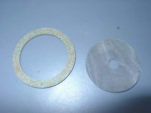
136 Change
137
138 MTH35SP OPERATOR MAINTENANCE PROCEDURES INTRODUCTION This section contains Operator Maintenance applicable to the MTH35SP as authorized by the Maintenance Allocation Chart (MAC) in WP 0044 of this manual. All maintenance procedures in this section can be performed by one person unless otherwise indicated. Read all WARNINGs, CAUTIONs, and NOTEs carefully before attempting the procedures. This includes the warnings at the front of this manual. Each maintenance item will include a heading which lists the action to be taken, the tools and parts/materials required, and the condition the equipment must be in to perform the action. END OF WORK PACKAGE /(2 Blank)
139 THIS PAGE INTENTIONALLY LEFT BLANK
140 OPERATOR MAINTENANCE MTH35SP FLAME SENSOR REPLACE INITIAL SETUP Tools Materials/Parts Wrench (Table 2, Item 2, WP ) Flame sensor (Item 9, WP ) Equipment Condition Heater shut down and all advisory lights off. (WP ) In-tent controller assembly disconnected from heater. (WP ) Fuel supply disconnected. (WP ) Battery disconnected. (WP ) CAUTION Disconnect battery connector. Before performing any maintenance actions, be sure to disconnect the battery to prevent component failure. Failure to comply may result in damage to electrical components. REPLACE 1. Disconnect battery pack connector (1) from lower housing assembly. 2. Remove the upper housing assembly (2) by first removing the two dust covers (3) at the inlet and outlet ends of the heater. 3. Remove the two duct adapters (4) at the inlet and outlet end of the heater by releasing the two fastener housings (5) from the fastener keepers (6). 4. Remove the upper housing assembly (2) by releasing the remaining fastener housings (7) from their corresponding fastener keepers (8). Lift and remove the upper housing assembly (1). Set the upper housing assembly aside
141 Disconnect electrical connector (1) from flame sensor (2). 2. Using wrench (3) supplied with the heater, unscrew flame sensor (2) in counterclockwise direction from burner assembly (4). 3. Locate and remove new flame sensor (5) from spare storage area at the breathable air inlet end of the heater. 4. Screw new flame sensor (2) in clockwise direction into burner assembly (4). 5. Tighten securely with wrench (3). 6. Reconnect electrical connector (1)
142 NOTE! Spares and onboard tools are located inside the duct adapter located on the inlet side of the heater near the heated air blower assembly END OF WORK PACKAGE /(4 Blank)
143
144 OPERATOR MAINTENANCE MTH35SP GLOW PLUG REPLACE INITIAL SETUP Tools Materials/Parts Wrench, (item 2, WP ) Glow Plug, (item 10, WP ) Equipment Condition Heater shut down and all advisory lights off. (WP ) In-tent controller assembly disconnected from heater. (WP ) Upper housing assembly removed (WP ). Fuel supply disconnected. (WP ) Battery disconnected. (WP ) CAUTION Disconnect battery connector. Before performing any maintenance actions, be sure to disconnect the battery to prevent component failure. Failure to comply may result in damage to electrical components. REPLACE 1. Disconnect battery (1). 2. Disconnect electrical lead (2) from glow plug (3). 3. Using wrench (4) supplied with the heater, loosen and remove glow plug (3) from burner assembly (5) by turning in a counterclockwise direction. 4. Locate and remove a new glow plug (6) from the spare storage area (7) at the breathable air inlet end of the heater. Screw the replacement glow plug (3) in clockwise direction into burner assembly (5) and reconnect electrical lead (2)
145 Spares and onboard tools are located inside the duct adapter located on the inlet side of the heater near the heated air blower assembly END OF WORK PACKAGE
146
147 CHAPTER 5 UNIT MAINTENANCE INSTRUCTIONS SPACE HEATER, MTH35SP
148 THIS PAGE INTENTIONALLY LEFT BLANK
149 MTH35SP UNIT PREVENTIVE MAINTENANCE CHECKS AND SERVICES GENERAL This section lists the preventive checks and services to be performed quarterly by Unit Maintenance personnel. Refer to Operator PMCS WP 0010 for an explanation of PMCS procedures. PMCS TABLE The accompanying table provides a listing of PMCS to be performed by Unit personnel. It includes the following: Item Number Column. This column is a list of every check and service task in the PMCS. They are numbered in logical order of performance regardless of the interval. This column is to be used as a source of item numbers for the Th1 Number Column on DA Form 2404, Equipment Inspection and Maintenance Worksheet, in recording results of PMCS. Interval Column. This column indicates the interval at which a specific item needs to be checked or serviced. Item To Be Checked or Serviced Column. This column provides the name of the item to be checked or serviced. Procedure Column. This column describes the procedures used to check or service an item. It includes all the information required to perform the checks or services. Not Fully Mission Capable If: Column. This column indicates conditions under which the heater is not capable of performing its intended mission. LEAKAGE DEFINITIONS FOR UNIT PMCS It is necessary for you to know how fuel leaks affect the status of the heater. Following are classes of leaks you need to know to determine the operational status of the heater. Learn these leakage class definitions. Remember when in doubt, notify your supervisor Change 1
150 WARNING Seat the Fuel can adapter kit. The kit must be fully seated to prevent fuel leakage. Clean up all fuel spills. No leakage of any type is permitted within the heater. No leakage of any type is permitted within the area or compartment being heated. Leakage may present a fire and/or a health hazard. Failure to comply may result in serious injury or death. NOTE Leaking or spilled fuels will harm the environment. Follow all local requirements when cleaning up all fuel spills. Heater operation is allowed if: Class I or Class II leaks occur in fuel supply lines external to the heater. And, such leakage does not present a fire or health hazard. Class III leaks shall be reported immediately to your supervisor. CLASS I - Slight seepage of fuel, but not great enough to form a drop. Indicated by slight wetness or discoloration. CLASS II - Seepage of fuel great enough to form drops but not great enough to cause drops to drip from the item being checked. CLASS III - Leakage of fuel great enough to form drops that fall from the item being checked. Unit Preventive Maintenance Checks and Services. NOTE If the equipment must be kept in continuous operation, do only the procedures that can be done without disturbing operation. Make complete checks and services when the equipment is shut down. Table 1. Operator Preventive Maintenance Checks and Services. Item No. Interval Location Item to Check/Service Procedure NOTE Not Fully Mission Capable If: All necessary PMCS may be accomplished by the operator. END OF WORK PACKAGE Change
151 MTH35SP (SHC) UNIT MAINTENANCE PROCEDURES GENERAL The procedures in this section have been arranged in order in which the items appear in the Unit (0) Maintenance level column on the Maintenance Allocation Chart (MAC), which is provided in WP Step by step procedures have been provided for all actions authorized to be performed by the Unit in Chapter 4. CAUTION Disconnect battery connector. Before performing any maintenance actions, be sure to disconnect the battery to prevent component failure. Failure to comply may result in damage to electrical components. WIRING General. Preferred repair methods consist of replacing wires, terminals, connectors, etc., rather than splicing wires, bending ends to form terminals, and other makeshift procedures, although the latter may be appropriate for emergency field repairs. Soldering Connections. Wire connections must be made mechanically sound before they are soldered. Solder alone does not provide sufficient strength to prevent breakage. Joining surfaces of connections to be soldered must be clean and bright. If a separate flux is used, it should be rosin base flux and should be brushed onto the joint before soldering. If a flux-core solder is used, it should be a rosin core electrical solder. If uncored solder is used, it should be a lead-tin solder. Wires should always be heated to the point at which the solder will melt completely and flow into all parts of the joint. Excessive build up of solder gobs on the joint should be avoided or removed. Insulating Joints. The preferred method of insulating electrical joints is by the use of heat-shrink tubing. To apply, cut a piece of heat-shrink tubing of suitable diameter to a one-inch length for covering joints at terminals or connectors, or to a length about 1/2 inch (1.3 cm) longer than the joint to be insulated, and slide the tubing over the wire before making the joint. After the joint is made, slide the tubing so that it covers the joint, and shrink in place with moderate heat. Splicing Wires. To repair broken or cut wires that are otherwise sound, the mating ends can be stripped and spliced. A commercial butt splice can be crimped onto the ends to join them, or a Western Union wire splice can be made. The latter is made by stripping 1/4-1/2 inch ( mm) of insulation from the wire ends, holding the ends parallel and facing opposite directions, then twisting each end around the other wire at least three turns. Solder and apply insulation as described above. Crimping Terminals. To install a terminal on the end of a wire, strip 1/4-1/2 inch ( mm) of insulation from the end of the wire, apply a one-inch piece of heat-shrinking tubing (if the terminals are of the non-insulated type) and insert wire end into the shank of the terminal. Crimp the shank, and install heatshrink tubing, if necessary Change 1
152 CLEANING AND INSPECTION OF ANTIFRICTION BEARINGS Refer to TM 9-214, Inspection, Care, and Maintenance of Antifriction Bearings. CLEANING AND INSPECTION OF MECHANICAL PARTS WARNING Cleaning solvents are flammable, toxic, and hazardous to eyes, skin, and respiratory tract. Skin/eye protection is required. Avoid unprotected or repeated/prolonged contact. If contact with eyes is made, immediately flush with clean water and get medical first aid. Failure to comply may result in serious injury to personnel. Use only in well ventilated areas. Keep away from open flames or other sources of ignition. Compressed air used for cleaning purposes will not exceed 30 psi (kpa). Use only with effective personal eye/face protective equipment. Clean metal parts with alcohol. Thoroughly dry the parts with compressed air, observing all safety precautions. Fibrous or rubber parts can generally be cleaned with warm, soapy water and dried with compressed air. Inspect metal parts for cracks, breaks, bends, worn edges, and rough bearing surfaces. Damage that alters the part or its function is cause for replacement of that part. GENERAL REPAIR Repair the SHC to normal operating condition by replacing or repairing a defective component and/or by needed adjustments. Cleaning and lubrication is sometimes all that is needed to return an item to operating condition. Remove and replace only those items necessary to make repairs. After replacing the defective components, ensure that the SHC operates correctly. To paint metal, sand bear metal areas with sandpaper and refinish with primer and olive drab paint. Refer to TM for proper painting instructions. Allow paint to dry between coats. END OF WORK PACKAGE Change
153 UNIT MAINTENANCE MTH35SP IN-TENT CONTROLLER ASSEMBLY INSPECT, TEST, REPLACE INITIAL SETUP Tools Tool Kit, General Mechanics (Item 1, WP ) Materials/Parts Personnel Required One Equipment Condition Heater shut down and all advisory lights off. (WP ) INSPECT 1. Inspect the In-tent Controller Assembly connector (1) for cracks, dents to the outer collar, dirt in the contacts, or any other damage that would prevent the connector (1) from making a good electrical connection with the in-tent controller cable assembly (2). 2. Inspect the ON-OFF switch (3) and LOWER-HIGHER control (4) to ensure proper operation. 3. Ensure that each of the advisory lights (5) operate properly. 4. Ensure that all informational labels (6 and 7) are present and legible. TEST Using a multimeter, perform a short circuit test across all terminals (8) of the connector (1). For example, pin A to pin B, A to C, A to D, etc. Followed by B to A, B to C, B to D, etc. There should not be shorts across any of the pins. If shorts exist, replace the in-tent controller assembly. REPLACE 1. To replace the in-tent controller assembly (9), unscrew the outer collar (10) of the in-tent controller assembly cable (2) and disconnect cable from in-tent controller assembly (9). 2. Connect in-tent controller cable (2) to new in-tent controller assembly (9). 3. Tighten outer collar (10) of in-tent controller assembly cable (2) securely
154 END OF WORK PACKAGE
155 UNIT MAINTENANCE SPACE HEATER, MTH35SP IN-TENT CONTROLLER CABLE ASSEMBLY INSPECT, TEST, REPLACE INITIAL SETUP Tools Tool Kit, General Mechanics (Item 1, WP ) Materials/Parts Personnel Required One Equipment Condition Heater shut down. In-tent controller assembly cable disconnected from heater and in-tent controller assembly connector. INSPECT Inspect the In-tent Controller Cable Assembly connector (1) for cracks, dents to the outer collar, dirt in the contacts, or any other damage that would prevent the connector (1) from making a good electrical connection with the in-tent controller assembly connector (2)
156 TEST 1. Using a multimeter, perform a continuity check from pin A at one end of cable to pin A at opposite end of cable. Repeat for all pins. Ensure that there is continuity through the cable. 2. Using a multimeter, perform a short circuit test across all terminals of the connector. For example, test from pin A to pin B, A to C, A to D, etc. Followed by B to A, B to C, B to D, etc. There should not be shorts across any of the pins. If shorts exist, replace the in-tent controller assembly cable. 3. If there is a lack of continuity through the cable or shorts within either of the connectors, replace the in-tent controller cable assembly. REPLACE 1. Ensure that the in-tent controller cable assembly has been completely disconnected from the heater and the in-tent controller assembly. 2. Connect new cable to the heater and to the in-tent controller assembly. Secure connectors at both ends of in-tent controller assembly cable. END OF WORK PACKAGE
157 UNIT MAINTENANCE MTH35SP BATTERY PACK ASSY INSPECT, TEST, REPLACE INITIAL SETUP Tools Tool Kit, General Mechanics (Item 1, WP ) Materials/Parts Personnel Required One Equipment Condition Heater shut down and all advisory lights off. (WP ) In-tent controller assembly disconnected from heater. (WP ) CAUTION Disconnect battery connector. Before performing any maintenance actions, be sure to disconnect the battery to prevent component failure. Failure to comply may result in damage to electrical components. INSPECT 1. Disconnect battery pack assembly (1). 2. Inspect battery pack electrical connector (2). Ensure that connector (2) is not cracked or damaged in any way. Ensure that all wires (3) leading from battery pack (1) to connector housing are free of cuts, abrasions, or any other damage that would expose bare wire. 3. Inspect the two fuse holders (4) on the side of the battery pack (1) and ensure that there are no cracks or other damage that would prevent the fuse holders from securing the fuse and maintaining proper electrical contact. 4. Ensure that there are no cracks, cuts, or other damage to the outer casing of the battery pack (1). 5. If there is any damage to the connector (2), fuse holders (4), or wiring (3), the battery pack should be replaced Change 1
 are in good electrical working order by removing them from the fuse holders (2) on the left side of the battery pack (3) and testing")
158 TEST 1. Before replacing the battery pack, ensure that the two fuses (1) are in good electrical working order by removing them from the fuse holders (2) on the left side of the battery pack (3) and testing for continuity with a multi-meter. NOTE Continuity through the fuse ensures that it is in good electrical working order. 2. If there is no continuity through the fuse, replace it with a known good fuse from the on-board spare parts (4) located at the inlet end (5) of the heater. If the fuses are both in good electrical working order and the battery pack is not supplying power to the heater. 3. Check the battery voltage without a load. There are two battery circuits in the battery pack. 4. Use a voltmeter to check the voltage on one battery circuit in the pack by inserting the voltmeter probes into the red and black wire pockets in the battery connector (6). It should read 12.5 to 13.0 volts. 5. Check the other battery circuit in the pack by inserting the voltmeter probes in the green and white wire pockets in the battery connector (6). It should read 12.5 to 13.0 volts. 6. If either of the two battery circuits in the pack does not read 12.5 to 13.0 volts, recharge the battery. Change

159 SERVICE Under normal conditions, the Space Heater, MTH35SP is responsible for recharging the on-board battery pack. However, there may be some instances where it is required that the battery be recharged using a commercially available 115 VAC to 12 VDC charger. To accomplish this, a battery-charging adapter has been supplied with the heater that permits the connection of a charger to the battery pack. CAUTION Do not permit the battery charger terminals to come in contact with the metal casing of the heater. Failure to comply may cause damage to the charger, battery pack assembly, or the electrical components. NOTE No grounding is necessary when using the battery-charging adapter. 1. To charge the battery (1) with a commercial 115 VAC to 12 VDC battery charger, disconnect the battery connector (2) from the heater and engage the connector on the end of the battery-charging adapter with the connector on the battery pack. 2. Connect the positive (+) lead of the charger to the red (+) wire (3) of the battery-charging adapter and the negative (-) lead of the charger to the black (-) wire (4) of the battery-charging adapter. Once the charger is connected to the battery-charging adapter properly, turn on the power to the charger Change 1
160 Depending upon the battery temperature, recharge time for the battery will be approximately 30 minutes. The battery will take longer to recharge in cold weather conditions REPLACE 1. Before replacing the battery pack, an attempt should be made to recharge the battery pack in accordance with the Service section of this work package. If the battery is incapable of retaining a charge and will not start the heater, it should be replaced. 2. To remove the battery pack (1), remove the battery pack retainer (2) by removing the two screws (3) on either side of the retainer (2). Remove the retainer. 3. Disconnect the battery pack connector (4) by unplugging from portion of connector mounted in side of heater. 4. Slide the battery pack (1) out of the recess (5) on the side of the heater. 5. Dispose of the battery pack (1) in accordance with appropriate military and/or local regulations. 6. Install a new battery pack (1) into the recess (5) on the side of the heater. Be sure to orient the connector (4) on the side of the battery pack so that it aligns with the connector (6) installed on the side of the heater. Engage both halves of the connector and ensure that are firmly mated. Change
 that secure the retainer.")
161 Install the retainer (2) in place over the battery pack (1). Install and secure the two screws (3) that secure the retainer END OF WORK PACKAGE Change 1
162 UNIT MAINTENANCE MTH35SP FUEL SUPPLY QUICK DISCONNECT INSPECT, REPLACE INITIAL SETUP Tools Materials/Parts Tool Kit, General Mechanics (Item 1, WP 0044 Rags (Item 5, WP ) 00) Sealant, thread (Item 3, WP ) Personnel Required Equipment Condition One Heater shut down and all advisory lights off. (WP ) In-tent controller assembly disconnected from heater. (WP ) Battery disconnected. (WP ) Fuel supply disconnected. (WP ) CAUTION Disconnect battery connector. Before performing any maintenance actions, be sure to disconnect the battery to prevent component failure. Failure to comply may result in damage to electrical components. INSPECT Inspect the fuel supply quick disconnect (1) to ensure there are no cracks, dents, or other damage that would prevent the external fuel hose from attaching securely to the quick disconnect. There should be no fuel leaks when the fuel hose is attached. REMOVE 1. To remove the fuel supply quick disconnect (1), use a wrench and loosen the fuel supply quick disconnect from the elbow fitting (2) that is attached to the fuel solenoid valve (3). 2. Remove the fuel supply quick disconnect Change 1
163 REPLACE 1. Clean all residual sealant that may be present inside the elbow (2). 2. Apply new sealant to the threads (4) of the fuel quick disconnect (1). 3. Install the fuel quick disconnect into the elbow fitting (2). Tighten securely END OF WORK PACKAGE Change
164 UNIT MAINTENANCE MTH35SP FUEL SUPPLY QUICK DISCONNECT INSPECT, REPLACE INITIAL SETUP Tools Materials/Parts Tool Kit, General Mechanics (Item 1, WP 0044 Rags (Item 5, WP ) 00) Sealant, thread (Item 3, WP ) Personnel Required Equipment Condition One Heater shut down and all advisory lights off. (WP ) In-tent controller assembly disconnected from heater. (WP ) Battery disconnected. (WP ) Fuel supply disconnected. (WP ) CAUTION Disconnect battery connector. Before performing any maintenance actions, be sure to disconnect the battery to prevent component failure. Failure to comply may result in damage to electrical components. INSPECT Inspect the fuel supply quick disconnect (1) to ensure there are no cracks, dents, or other damage that would prevent the external fuel hose from attaching securely to the quick disconnect. There should be no fuel leaks when the fuel hose is attached. REMOVE 1. To remove the fuel supply quick disconnect (1), use a wrench and loosen the fuel supply quick disconnect from the elbow fitting (2) that is attached to the fuel solenoid valve (3). 2. Remove the fuel supply quick disconnect Change 1
165 REPLACE 1. Clean all residual sealant that may be present inside the elbow (2). 2. Apply new sealant to the threads (4) of the fuel quick disconnect (1). 3. Install the fuel quick disconnect into the elbow fitting (2). Tighten securely END OF WORK PACKAGE Change
166 UNIT MAINTENANCE MTH35SP FUEL SOLENOID VALVE AND SEDIMENT STRAINER ASSEMBLY INSPECT, SERVICE, REPLACE INITIAL SETUP Tools Materials/Parts Tool Kit, General Mechanics (Item 1, WP ) Gasket (Item 11, WP ) Screen (Item 12, WP ) Rags, Wiping, Clean (Item 5, WP ) Sealant, Thread (Item 3, WP ) Mat, Petroleum Absorbent (Item 15, WP ) Wrap, Tie (Item 16, WP ) Personnel Required Equipment Condition One Heater shut down down all advisory lights off. (WP ). In-tent controller assembly disconnected from heater. (WP ) Battery disconnected. (WP ) Fuel supply disconnected. (WP ) CAUTION Disconnect battery connector. Before performing any maintenance actions, be sure to disconnect the battery to prevent component failure. Failure to comply may result in damage to electrical components. INSPECT 1. Inspect the sediment strainer (1) for any cracks, dents, or other damage that would restrict the flow of fuel from the fuel solenoid valve (2) to the fuel hose (3). 2. Ensure that there are no fuel leaks at the fittings (4) or around the bowl area (5) of the strainer. 3. Inspect the fuel solenoid valve (2) for any cracks, dents, or other damage that would inhibit its proper operation or restrict the flow of fuel from the fuel solenoid valve (2) to the sediment strainer (1). 4. Ensure that the wires (6) protected by the wire loom (7) and leading to the fuel solenoid valve (1) do not have any cuts or abrasions. 5. Inspect the connectors (8) for any cracks or other damage that would prevent the connectors from having a secure electrical connection Change 1
 slightly and remove it from the sediment strainer top assembly (5). 4. Empty the fuel from the bowl (3) into an approved container and discard.")
167 SERVICE 1. To clean and service the sediment strainer (1), loosen the knurled nut (2) at the base of the sediment strainer bowl (3). 2. Rotate the bale (4) to the right and upward while supporting the bowl (3). 3. Rock the bowl (3) slightly and remove it from the sediment strainer top assembly (5). 4. Empty the fuel from the bowl (3) into an approved container and discard. Do not empty the fuel into a fresh fuel supply. 5. Remove the gasket (6) and screen (7) from the sediment strainer top assembly (5) and discard in an approved manner. 6. Install a new gasket (6) and screen (7) in position on the sediment strainer top assembly (5). 7. Replace the bowl (3) under the sediment strainer top assembly (5). 8. Rotate the bale (4) downward and center under the bowl (3). Change
 at base of sediment strainer")
168 Tighten knurled nut (2) at base of sediment strainer bowl (3) Change 1
169 REPLACE CAUTION Thread sealant is used to seal the threads on the various fittings of the fuel solenoid and sediment strainer assembly. Once the sealant has set, it may require some force to break the sealant s bond. However, take care not to apply excessive force which could result in damage to the components. 1. Before removing the fuel solenoid valve and sediment strainer assembly (1), drain the sediment strainer (2) of fuel by loosening the knurled nut (3) at the base of the sediment strainer bowl (4). 2. Rotate the bale (5) upward while supporting the bowl (4). 3. Rock the bowl (4) slightly and remove it from the sediment strainer top assembly (6). 4. Empty the fuel from the bowl (4) into an approved container and discard. Do not empty the fuel into a fresh fuel supply. Replace the bowl (4), rotate the bale (5) downward and center under the bowl. Tighten the knurled nut (3) taking care not to over tighten. 5. Cut the tie wrap (7) securing the wire loom (21) that protects the fuel solenoid valve electrical connectors and wires (8) to the sediment strainer outlet fitting (9). Remove the wire loom (21) by separating at the seam and lifting off the wires. Disconnect the fuel solenoid valve connectors (8). 6. Remove the protective dust cap (10) from the fuel quick disconnect (11). 7. Remove the fuel quick disconnect (11) as detailed in WP 0020 and set aside. 8. Using a wrench, remove the fuel quick disconnect elbow fitting (12) and set aside. 9. Wrap a rag around the end of the fuel hose (13) and grasp the end of the fuel hose near the fuel hose fitting (14) with a pair of pliers. Be sure that the rag is between the hose and the pliers so as to protect the hose from damage. 10. While holding the fuel hose (13) securely, use a wrench to loosen the fuel hose fitting (14). Remove the fuel hose fitting (14) from the sediment strainer outlet fitting (9). Have a petroleum absorbent mat or tray with absorbent material nearby to collect any fuel that may be in the fuel hose. 11. Remove the two screws (15) and protective dust cap (10) that secure the fuel solenoid valve (16) to the external fuel system bracket (17). 12. While rotating the fuel solenoid valve and sediment strainer assembly (1) back and forth slightly toward and away from the heater, slide the assembly (1) to the right until the solenoid valve inlet fitting (18) clears the external fuel system bracket (17). 13. Drop the left end of the assembly with the solenoid valve inlet fitting (18) down below the bracket (17) and slide the assembly (1) to the left while rotating slightly as described above. Continue until the assembly (1) clears the sediment strainer bracket (19) and rubber grommet (20) to the right of the sediment strainer. Change
170 NOTE Protective rubber dust cap (10) removed from fuel quick disconnect (11) for illustrative purposes * * fitting (18) is between elbow (12) and solenoid (16). Change
171 To install a new solenoid valve and sediment strainer assembly (1), insert the sediment strainer outlet fitting (9) into the rubber grommet (20) on the sediment strainer bracket (19) closest the fuel hose (13). Continue until the solenoid valve inlet fitting (18) has cleared the external fuel system bracket (17). 15. Swing the left end of the assembly with the solenoid valve inlet fitting (18) under the external fuel system bracket (17) and insert the fuel solenoid inlet fitting (18) into the hole on the external fuel system bracket (17). 16. Rotate the assembly (1) while sliding the assembly to the left until the holes on the top of the fuel solenoid valve (16) are aligned with the holes on the external fuel system bracket (17). 17. Install the two screws (15) and protective dust cap (10) through the external fuel system bracket (17) and into the fuel solenoid valve (16). Tighten securely. 18. Wrap a rag around the end of the fuel hose (13) and grasp the end of the fuel hose near the fuel hose fitting (14) with a pair of pliers. Be sure that the rag is between the hose and the pliers in order to protect the hose from damage. 19. While holding the fuel hose (13) securely, use a wrench to engage the fuel hose fitting (14) on the sediment strainer outlet fitting (9). Make sure that the fittings (9 and 14) engage correctly and do not cross-thread. Tighten the fuel hose fitting (14) securely. 20. Clean any residual thread sealant from the threads of the fuel quick disconnect elbow fitting (12) that was removed and set aside earlier. Apply new thread sealant to the threads of the fuel solenoid inlet fitting (18). Tighten the fuel quick disconnect elbow fitting (12) securely taking care to align the opening (22) on the elbow fitting (12) so that it faces outward. 21. Clean any residual thread sealant from threads of the fuel quick disconnect (11). 22. Apply new thread sealant to the threads of the fuel quick disconnect (11). 23. Install the fuel quick disconnect (11) into the fuel quick disconnect elbow fitting (12) and tighten securely. 24. Reconnect the fuel solenoid valve electrical connectors (8). Install the wire loom (21) over the fuel solenoid wires and connectors (8). Install a new tie wrap (7) over the wire loom (21) and bracket (19) to secure the wire loom to the sediment strainer outlet fitting (9). Change
 is between elbow (12) and solenoid (16).")
172 NOTE Protective rubber dust cap (10) removed from fuel quick disconnect (11) for illustrative purposes * * fitting (18) is between elbow (12) and solenoid (16). 22 Change

173 END OF WORK PACKAGE Change
174
175 UNIT MAINTENANCE MTH35SP FUEL HOSE INSPECT, REPLACE INITIAL SETUP Tools Materials/Parts Tool Kit, General Mechanics (WP , Item 1) Rags, Wiping, Clean (Item 5, WP ) Mat, Petroleum Absorbent (Item 15, WP ) Wrap, Tie (Item 16, WP ) Personnel Required Equipment Condition One Heater shut down and all advisory lights off. (WP ) In-tent controller assembly disconnected from heater. (WP ) Fuel supply disconnected. (WP ) Sediment strainer bowl empty of fuel. (WP ) Battery disconnected. (WP ) Upper housing assembly removed. (WP ) CAUTION Disconnect battery connector. Before performing any maintenance actions, be sure to disconnect the battery to prevent component failure. Failure to comply may result in damage to electrical components. INSPECT 1. Inspect the fuel hose (1) and fittings (2) for any cuts, abrasions, dents, or other damage that may cause the fuel hose to leak. 2. Inspect the rubber grommet (3) where the fuel hose passes through the side of the lower housing assembly for any damage that would prevent it from protecting the fuel hose from the sheet metal edges of the lower housing assembly. REPLACE 1. To remove the fuel hose (1), cut and remove the tie wraps (4) that secure the wire loom (6) to the sediment strainer outlet fitting (7) and the fuel hose (1). 2. Move the wire loom (6) and enclosed wires out of the vicinity of the fuel hose (1) Change 1
176 Wrap a rag around the end of the fuel hose (1) connected to the sediment strainer outlet fitting (7) and grasp the end of the fuel hose near the fuel hose fitting (9) with a pair of pliers. Be sure that the rag is between the hose and the pliers to protect the hose from damage. 4. Holding the fuel hose (1) securely, use a wrench to loosen the fuel hose fitting (9). Remove the fuel hose fitting (9) from the sediment strainer outlet fitting (7). Have a petroleum absorbent mat or tray with absorbent material nearby to collect any fuel that may be in the fuel hose. 5. Wrap a rag around the end of the fuel hose (1) which is connected to the float assembly inlet fitting (10) and grasp the end of the fuel hose near the fuel hose fitting (11) with a pair of pliers. Be sure that the rag is between the hose and the pliers to protect the hose from damage. 6. Holding the fuel hose (1) securely, use a wrench to loosen the fuel hose fitting (11). Remove the fuel hose fitting (11) from the float assembly inlet fitting (10). Place a small section of petroleum absorbent mat at the base of the lower heater housing to collect any residual fuel that may be in the fuel hose. 7. Pull the fuel hose and rubber grommet (3) out through the opening in lower housing assembly. Remove the grommet from the hose and re-install it back in the lower housing assembly opening. 8. Install a new fuel hose by inserting the end of the fuel hose with the fitting that installs to the sediment strainer assembly through the rubber grommet (3) from the inside of the heater, guiding it out of the lower heater housing. It may be easier to insert the fuel hose through the grommet by wetting the inside surface of the grommet. Move the fuel hose fitting (11) into position near the float assembly inlet fitting (10). 9. Wrap a rag around the end of the fuel hose (1) which is to be connected to the float assembly inlet fitting (10) and grasp the end of the fuel hose near the fuel hose fitting (11) with a pair of pliers. Be sure that the rag is between the hose and the pliers to protect the hose from damage. 10. Holding the fuel hose (1) securely, use a wrench to tighten the fuel hose fitting (11) securely. 11. Wrap a rag around the end of the fuel hose (1) which is to be connected to the sediment strainer outlet fitting (7) and grasp the end of the fuel hose near the fuel hose fitting (9) with a pair of pliers. Be sure that the rag is between the hose and the pliers to protect the hose from damage. 12. Holding the fuel hose (1) securely, use a wrench to tighten the fuel hose fitting (9) onto the sediment strainer outlet fitting (7). 13. Install a new tie wrap (4) in the same location as before and secure the wire loom (6) to the sediment strainer outlet fitting (7) and the fuel hose (1). Change

")
177 END OF WORK PACKAGE /(4 Blank) Change 1
178
179 UNIT MAINTENANCE MTH35SP HEATER CONTROL ASSEMBLY REPLACE INITIAL SETUP Tools Tool Kit, General Mechanics (Item 1, WP ) Personnel Required One Materials/Parts Equipment Condition Heater shut down and all advisory lights off. (WP ) In-tent controller assembly disconnected from heater. (WP ) Fuel supply disconnected. (WP ) Battery disconnected. (WP ) Upper housing cover removed. (WP ) CAUTION Disconnect battery connector. Before performing any maintenance actions, be sure to disconnect the battery to prevent component failure. Failure to comply may result in damage to electrical components. REPLACE 1. To replace the heater control assembly (1), remove the combustion air inlet cover (2) by rotating the two quarter turn screws (3) until they release. Put the cover (2) aside. 2. Remove the four screws (4) that secure the heater control assembly (1) to the side wall of the lower housing assembly (5). 3. Lift the heater control assembly (1) partially out of the heater and remove the two connectors (6 and 7) on the left side of the heater control assembly by depressing the connector locks (8) and wiggling the connector back and forth while pulling outward. 4. Remove the heater control assembly from the lower housing assembly. 5. Install a new heater control assembly (1) by putting it into position on the lower housing assembly (5). 6. Connect the two connectors (6 and 7) by engaging into the connectors on the heater control assembly (1) and pushing in until the connectors lock Change 1
 on the outside")
 and")

180 Install the four mounting screws (4) on the outside of the lower housing assembly (5) and secure. 8. Install the combustion air inlet cover (2) and secure by pushing in on the quarter turn screws (3) and rotating until they lock into position END OF WORK PACKAGE Change
181 UNIT MAINTENANCE MTH35SP WIRE HARNESS INSPECT, REPAIR INITIAL SETUP Tools Materials/Parts Tool Kit., General Mechanics (Item 1, WP ) Tape, Electrical (Item 7, WP ) Wrap, Tie (Item 16, WP ) Equipment Condition Heater shut down and all advisory lights off. (WP ) In-tent controller assembly disconnected from heater. (WP ) Fuel supply disconnected. (WP ) Battery disconnected. (WP ) Upper housing assembly removed. (WP ) CAUTION Disconnect battery connector. Before performing any maintenance actions, be sure to disconnect the battery to prevent component failure. Failure to comply may result in damage to electrical components. INSPECT 1. Inspect the connectors (1) on the wire harness to ensure that all connectors are securely mated and locked together. 2. Inspect the wire (2) for any cuts or abrasions to the insulation that would expose bare wire. Repair any breaks or abrasions as detailed below. 3. Inspect the tie wraps (3) and ensure that none are broken or cut. Replace any tie wraps that are damaged. REPAIR 1. Repair any cuts or abrasions on the wires (2) with electrical tape, wrapping each repaired area with at least two layers of tape. 2. Repair tie wraps (3) by removing any broken pieces and installing a new tie wrap Change 1
182 END OF WORK PACKAGE Change
183 UNIT MAINTENANCE MTH35SP POWER CONTROL ASSEMBLY REPLACE INITIAL SETUP Tools Materials/Parts Tool Kit, General Mechanics (Item 1, WP ) Tags, marking, MIL-T (Item 6, WP ) Equipment Condition Heater shut down and all advisory lights off. (WP ) In-tent controller assembly disconnected from heater. (WP ) Fuel supply disconnected. (WP ) Battery disconnected. (WP ) Upper housing assembly removed (WP ) CAUTION Disconnect battery connector. Before performing any maintenance actions, be sure to disconnect the battery to prevent component failure. Failure to comply may result in damage to electrical components. REPLACE 1. To remove the power control assembly (1), tag or mark the five wires (2) that are attached to the top edge of the power control assembly so that they match the numbers labeled on the heater control assembly printed circuit board. 2. Remove the two connectors (3 and 4) on the left and right side of the the power control assembly. 3. Loosen and remove each of the five wires (2) from the top edge of the power board assembly. 4. Remove the screws (5) that secure the power control assembly (1) to the lower housing assembly (6). 5. Remove the power control assembly (1) from the heater housing Change 1
 by putting it into position on the lower housing")
 with spade lugs to their original position along the top edge of")

184 Install a new power control assembly (1) by putting it into position on the lower housing assembly (6). 7. Install the four mounting screws (5) and secure. 8. Install the five wires (2) with spade lugs to their original position along the top edge of the power control assembly. Be sure that the number marked on each wire matches the number labeled on the heater control assembly board. 9. Install the two connectors (3 and 4) on the left and right side of the power control assembly (1) END OF WORK PACKAGE Change
185 UNIT MAINTENANCE MTH35SP IGNITION PACK ASSEMBLY REPLACE INITIAL SETUP Tools Tool Kit., General Mechanics (Item 1, WP ) Materials/Parts Equipment Condition Heater shut down and all advisory lights off. (WP ) In-tent controller assembly disconnected from heater. (WP ) Fuel supply disconnected. (WP ) Battery disconnected. (WP ) Upper housing assembly removed (WP ) CAUTION Disconnect battery connector. Before performing any maintenance actions, be sure to disconnect the battery to prevent component failure. Failure to comply may result in damage to electrical components. REPLACE 1. To remove the ignition pack assembly (1), separate the two halves of the connector (2) exiting the top of the ignition pack assembly. 2. Remove the wire (3) connecting the ignition pack (1) to the glow plug (4). 3. Remove the two screws (5) that secure the ignition pack assembly to the lower housing assembly (6). 4. Remove the ignition pack assembly (1) from the heater. 5. Install a new ignition pack assembly (1) by placing it in position on the lower housing assembly (6). 6. Install the two screws (5) and secure. 7. Mate and secure the two halves of the connector (2) going to the top of the ignition pack assembly (1) Change 1
")
 to the glow")

186 Connect the wire (3) connecting the ignition pack (1) to the glow plug (4) END OF WORK PACKAGE Change
187 UNIT MAINTENANCE MTH35SP DUST COVER ASSEMBLY INSPECT, REPLACE INITIAL SETUP Tools Materials/Parts Tool Kit, General Mechanics (Item 1, WP ) Alcohol (Item 2, WP ) Rags (Item 5, WP ) Equipment Condition Heater shut down and all advisory lights off. (WP ) WARNING Only clean parts in a well-ventilated area. Avoid inhalation of alcohol fumes or prolonged contact with skin. If contact with eyes is made, immediately flush with clean water and get medical first aid. Failure to comply may result in injury to personnel. INSPECT 1. Inspect the dust cover (1) for any dents, cracks, cuts, or other damage that would prevent the dust cover from covering the duct adapter and properly protecting the heater from dust, sand, or other foreign matter. 2. Inspect the chain (2) for any cuts or breaks that would prevent it from securing the dust cover to the lower housing of the heater. 3. Wipe dust cover (1) thoroughly with a clean, dry rag. For oily or stubborn dirt, moisten rag with alcohol. REPLACE 1. Pull dust cover (1) off duct adapter (3). 2. Remove screw (4), lock washer (5), flat washer (6), nut (7), chain (2), and dust cover (1). Discard damaged dust cover. 3. Position chain over hole in lower housing and install screw (4), lock washer (5), flat washer (6), and nut (7). 4. Install dust cover (1) on duct adapter (2) Change 1


188 END OF WORK PACKAGE Change
189 UNIT MAINTENANCE MTH35SP COMBUSTION AIR BLOWER ASSEMBLY REPLACE INITIAL SETUP Tools Tool Kit, General Mechanics (Item 1, WP ) Materials/Parts Equipment Condition Heater shut down and all advisory lights off. (WP ) Fuel supply disconnected. (WP ) Battery disconnected. (WP ) Upper housing assembly removed (WP ) CAUTION Disconnect battery connector. Before performing any maintenance actions, be sure to disconnect the battery to prevent component failure. Failure to comply may result in damage to electrical components. REPLACE 1. Remove the combustion air inlet cover (1) by releasing the two quarter turn screws at either end of the cover. Remove the cover (1) and set aside. 2. Remove the two screws (2) that secure the combustion air inlet end fitting bracket (3) to the lower housing assembly. Set the bracket aside. 3. Remove the combustion air inlet end fitting (4) from the combustion air inlet hose (5) and set aside. 4. Remove the two screws and lockwashers (13) that secure the combustion air blower assembly (8) to the heated air blower housing (14). 5. Remove the screw (6) that secures the blower assembly clamp (7) around the body of the combustion air blower assembly (8). 6. Disconnect the combustion air blower assembly duct (9) from the combustion air blower outlet (10) by loosening the hose clamp (11) and pulling the duct (9) from the combustion air blower outlet (10) Change 1
190 Disconnect the two combustion air blower electrical connectors (12). 8. Carefully lift the combustion air blower assembly (8) from the heater guiding the combustion air inlet hose (5) through the side wall of the lower housing. 9. Remove the blower assembly clamp (7) and set aside. 10. Disconnect the combustion air blower assembly (8) from the combustion air inlet hose (5) by loosening the hose clamp (15). 11. Install a new combustion air blower assembly (8) by installing the combustion air inlet hose (5) on the intake (16) of the combustion air blower assembly. Tighten hose clamp (11) securely. 12. Install the blower assembly clamp (7) on the body of the combustion air blower assembly (8). 13. Lower the combustion blower assembly (8) into the lower housing, guiding the combustion air inlet hose (5) through the hole (17) in the side wall of the lower housing. 14. Connect electrical connectors (12). 15. Tighten the screw (6) the secures the clamp (7) to the body of the combustion air blower assembly. 16. Tighten the screws (2) that secures the clamp (7) to the heated air blower assembly (8). 17. Install the combustion air blower duct (9) onto the outlet (10) of the combustion air blower assembly. Be sure that the rubber sleeve in the duct is installed on the outlet before installing the blower duct. Tighten the hose clamp (11) securely. 18. Install the combustion air inlet end fitting (4) on the end of the combustion air inlet hose (5). 19. Install the combustion air inlet bracket (3). Secure with two screws (2). 20. Install the combustion air inlet cover (1). Secure the two, quarter turn screws. Change

")
191 END OF WORK PACKAGE /(4 Blank) Change 1
192
193 UNIT MAINTENANCE MTH35SP COMBUSTION AIR BLOWER DUCT ASSEMBLY REPLACE INITIAL SETUP Tools Tool Kit, General Mechanics (Item 1, WP ) Personnel Required One Materials/Parts Equipment Condition Heater shut down and all advisory lights off. (WP ) In-tent controller cable assembly disconnected from heater. (WP ) Fuel source disconnected. (WP ) Battery disconnected. (WP ) Upper housing assembly removed (WP ) CAUTION Disconnect battery connector. Before performing any maintenance actions, be sure to disconnect the battery to prevent component failure. Failure to comply may result in damage to electrical components. REPLACE 1. Disconnect the combustion air blower duct assembly (1) from the burner assembly (2) by first loosening the hose clamp (3) and sliding it onto the hose (1). 2. Pull the end of the duct (1) from the burner assembly (2). 3. Disconnect the end of the combustion air blower duct assembly (1) connected to the combustion air blower assembly outlet (4) by loosening the hose clamp (5) and sliding it onto the hose (1). 4. Remove the combustion air blower duct assembly (1) from the heater. Be sure to remove the rubber spacer sleeve located inside the end of the duct assembly and reinstall it onto the combustion air blower assembly outlet (4). 5. To install the combustion air blower assembly hose (1), connect the combustion air blower duct assembly to the burner assembly (2) by sliding it onto the hose inlet on the burner assembly (2). Tighten the hose clamp (3). 6. Slide the end of the combustion air blower duct assembly onto the combustion air blower assembly outlet (4). Slide the hose clamp (5) into position and tighten Change 1

194 END OF WORK PACKAGE Change
195 UNIT MAINTENANCE MTH35SP COMBUSTION AIR INLET ASSEMBLY REPLACE INITIAL SETUP Tools Tool Kit, General Mechanics (Item 1, WP ) Materials/Parts Equipment Condition Heater shut down and all advisory lights off. (WP ) In-tent controller assembly disconnected from heater. (WP ) Fuel source disconnected. (WP ) Upper housing assembly removed (WP ) CAUTION Disconnect battery connector. Before performing any maintenance actions, be sure to disconnect the battery to prevent component failure. Failure to comply may result in damage to electrical components. REPLACE 1. To replace the combustion air inlet assembly (1), turn the two, quarter-turn screws (2) securing the combustion air inlet cover (3) until they release and remove the cover from the lower housing assembly (4). 2. Remove the two screws (5) that secure the combustion air inlet assembly bracket (6) to the lower housing assembly (4). 3. Grasp the combustion air inlet fitting (7) and pull it off the end of the combustion air inlet assembly (1). 4. Loosen the hose clamp (8) on the end of the combustion air inlet assembly (1) that connects to the combustion air blower assembly inlet (9) located inside the heater and pull the combustion air inlet assembly off the combustion air blower assembly inlet (9). Remove the clamp (8) from the combustion air inlet assembly (1) and set aside. 5. Pull the combustion air inlet assembly (1) out of the heater from the outside of the lower housing assembly (4) Change 1
, insert the longer end of the assembly into the opening on the lower housing assembly (4) and rotate it into position under the combustion blower")
 securely. 8.")
196 To install a new combustion air inlet assembly (1), insert the longer end of the assembly into the opening on the lower housing assembly (4) and rotate it into position under the combustion blower assembly inlet (9). Slide the hose clamp (8) over the end of the combustion air inlet assembly (1). 7. Install the combustion air inlet assembly (1) over the combustion air blower assembly inlet (9). Note that a slight back and forth rotating motion may be required. Tighten the hose clamp (8) securely. 8. Position the combustion air inlet assembly (1) against the lower housing assembly (4) and install the combustion air inlet fitting (7) over the end of the combustion air inlet assembly. 9. Position the bracket (6) over the end of the combustion air inlet (1). Secure with two screws (5). 10. Install the combustion air inlet cover (3) and secure with two quarter-turn screws (2) END OF WORK PACKAGE Change
197 UNIT MAINTENANCE MTH35SP UPPER HOUSING ASSEMBLY SERVICE, REPLACE INITIAL SETUP Tools Materials/Parts Tool Kit, General Mechanics (Item 1, WP ) Silicone lubricant (Item 4, WP ) Equipment Condition Heater shut down and all advisory lights off. (WP ) CAUTION Disconnect battery connector. Before performing any maintenance actions, be sure to disconnect the battery to prevent component failure. Failure to comply may result in damage to electrical components. SERVICE Lubricate slide portion (1) and pivot (2) of adjusting handle (3) with silicone lubricant. REPLACE 1. To replace the upper housing assembly (4), remove the two dust covers (5) and set aside. 2. Release the fasteners (6) that secure the two duct adapters (7) to the heater housing (8). Remove the two duct adapters (7) and set aside. 3. Release the four fasteners (9) that secure the upper housing assembly (4) to the lower housing assembly (10). 4. Lift the upper housing assembly (4) up and off the lower housing assembly (10). 5. Install a new upper housing assembly (4) and align with the lower housing assembly (10). Align the four fasteners (9) with their corresponding keeper plates. 6. Secure all four fasteners (9) Change 1

198 END OF WORK PACKAGE Change
199 UNIT MAINTENANCE MTH35SP (NSN ) EXHAUST GROMMET REPLACE INITIAL SETUP Tools Tool Kit, General Mechanics (Item 1, WP ) Personnel Required One Materials/Parts Equipment Condition Heater shut down and all advisory lights off. (WP ) In-tent controller assembly disconnected from heater. (WP ) Fuel source disconnected.(wp ) Battery disconnected. (WP ) Upper housing assembly removed (WP ) CAUTION Disconnect battery connector. Before performing any maintenance actions, be sure to disconnect the battery to prevent component failure. Failure to comply may result in damage to electrical components. REPLACE 1. To remove the exhaust grommet (1), remove the exhaust O-ring (2) and set aside. 2. Loosen the two wing nuts (3) that secure the burner assembly (4). Loosening the wing nuts will permit the heat exchanger (5) to be tilted upward to allow access to the grommet. 3. Tilt the end of the heat exchanger (5) upward and slide the grommet (1) up and out of the slotted recess on the lower housing assembly (6). 4. Stretch the grommet (1) over the ridge on the combustion exhaust pipe and slide the grommet off the combustion exhaust pipe (7). 5. Install a new exhaust grommet (1) by sliding the grommet over the combustion exhaust pipe (7). Lift up slightly on the heat exchanger (5) and engage the slot (8) in the grommet (1) over the sheet metal recess (9) on the lower housing assembly (6). 6. Press the exhaust grommet (1) down firmly Change 1
200 Slide the grommet onto the combustion exhaust pipe (7) and stretch the grommet (1) over the ridge on the combustion exhaust pipe. Install the exhaust O-ring (2) removed and set aside earlier. 8. Retighten the two wing nuts (3) that secure the burner assembly (4) END OF WORK PACKAGE Change
201 UNIT MAINTENANCE MTH35SP DUCT ADAPTER REPLACE INITIAL SETUP Tools Tool Kit, General Mechanics (Item 1, WP ) Personnel Required One Materials/Parts Equipment Condition Heater shut down and all advisory lights off. (WP ) Dust covers removed. (WP ) CAUTION Disconnect battery connector. Before performing any maintenance actions, be sure to disconnect the battery to prevent component failure. Failure to comply may result in damage to electrical components. REPLACE 1. To remove the duct adapter (1), lift and rotate the fastener housing (2), releasing it from the fastener keeper (3) on the upper housing assembly (4). 2. Repeat for the second fastener housing (5) and keeper on the opposite side of the duct adapter (1). 3. Pull the duct adapter (1) from the heater body (6). 4. To install a new duct adapter (1), align it over the end of the heater body (6) and press it into position. 5. Engage the fastener housings and keepers (2, 3 and 5) on both sides of the duct adapter (1) and secure in place Change 1


202 END OF WORK PACKAGE Change
203 UNIT MAINTENANCE MTH35SP HEATED AIR BLOWER ASSEMBLY INSPECT, TEST, REPLACE INITIAL SETUP Tools Tool Kit, General Mechanics (Item 1, WP ) Personnel Required One Materials/Parts N/A Equipment Condition Heater shut down and all advisory lights off. (WP ) In-tent control assembly disconnected from heater. (WP ) Fuel supply disconnected. (WP ) Battery disconnected. (WP ) Upper housing assembly removed (WP ) CAUTION Disconnect battery connector. Before performing any maintenance actions, be sure to disconnect the battery to prevent component failure. Failure to comply may result in damage to electrical components. INSPECT TEST 1. Inspect the heated air blower assembly (1) for cracks, dents, or other damage that would prevent the heated air blower assembly from rotating freely. 2. Inspect the inlet (2) and outlet (3) side of the heated air blower assembly (1) for any debris or blockages that would restrict the flow of air through the heater. 1. Separate the positive (+) (1) and negative (2) electrical connectors of the heated air blower assembly (3). 2. Set multi-meter to measure resistance. 3. Place probe No. 1 against positive terminal (1) and probe No. 2 against negative terminal (2). Normal meter indication is a minimum of 5.2 megohms. 4. If meter reading indicates a short or an open circuit, replace heated air blower assembly (3). 5. Reconnect the heated air blower assembly connector (1) and (2) Change 1
, remove any spare parts (2)")
. 3.")
 to the heater air blower assembly")
, position over the four")
204 REPLACE 1. To replace the heated air blower assembly (1), remove any spare parts (2) that may be stored in the corner holes of the vent fan and set aside. 2. Disconnect the heated air blower assembly connectors (3 and 4). 3. Loosen and remove the four screws (5), nuts (6), and lock washers (7) that mount the heated air blower assembly (1) to the heater air blower assembly housing (8). 4. Remove the heated air blower assembly (1). 5. To install the heater air blower assembly (1), position over the four holes on the heated air blower assembly housing (8). Change
. 5 3 4 2 1 2 8 0033 00-3 Change 1")
205 Install four screws (5), nuts (6), and lock washers (7) at the four corners of the heated air blower assembly (1). Tighten securely. 7. Reconnect heated air blower assembly electrical connectors (3 and 4) Change 1

206 END OF WORK PACKAGE Change
207 UNIT MAINTENANCE MTH35SP (NSN ) FUEL PUMP TEST, REPLACE INITIAL SETUP Tools Materials/Parts Tool Kit, General Mechanics (Item 1, WP ) Mat, Petroleum Absorbent (Item 15, WP ) Tray, Petroleum Absorbent (Item 17, WP ) Equipment Condition Heater shut down and all advisory lights off. (WP ) In-tent controller assembly disconnected from heater. (WP ) Fuel supply disconnected. (WP ) Battery disconnected. (WP ) Upper housing assembly removed. (WP ) CAUTION Disconnect battery connector. Before performing any maintenance actions, be sure to disconnect the battery to prevent component failure. Failure to comply may result in damage to electrical components. TEST 1. Disconnect the electrical connector (1). 2. Check the fuel pump (2) continuity with an ohmmeter. It should read 8 ohms. 3. If it has a reading other than 8 ohms, replace the fuel pump Change 1
208 REPLACE 1. To remove the fuel pump (2), disconnect the electrical connector (1). 2. Remove the screw (3) that secures the fuel pump bracket (4) to the lower housing assembly (5). 3. Loosen the screw (6) on the outlet hose (7) of the fuel pump (2) and pull the fuel line (8) out of the outlet hose (7). Drain any fuel onto a petroleum absorbent mat or tray. 4. Loosen and remove the fitting (9) on the float assembly (10). Drain any fuel onto a petroleum absorbent mat or tray. 5. Note the position of the fuel pump in the heater. The fuel pump must be reinstalled in the same position. Remove the fuel pump (2) from the heater and place on a petroleum absorbent mat or tray. Wipe up any fuel that may spill. 6. Remove the fuel pump bracket (4) and screw (3) and set aside. 7. While working on petroleum absorbent material, loosen and remove the fuel line (11) leading to the inlet end (12) of the fuel pump. Set the fuel line aside. 8. To install a new fuel pump, install the fuel line (11) to the inlet end (12) of the fuel pump. Tighten the fitting securely. 9. Slide the fuel pump bracket (4) over the new fuel pump and place the fuel pump (2) in position so that the fitting (9) on the end of the fuel line attached lines up with the T fitting (13) on the float assembly (10). 10. Position the fuel pump bracket (4) over the hole in the lower housing assembly (5) and install the screw (3). Tighten securely. 11. Engage the fitting (9) on the T fitting (13) of the float assembly (10) and tighten securely. 12. Install the fuel line (8) in the outlet hose (7) at the outlet end of the fuel pump and tighten the screw (6) on the hose clamp securely. 13. Install electrical connector (1). Change

209 Change 1


210 END OF WORK PACKAGE Change
211
212 UNIT MAINTENANCE MTH35SP INTERNAL FUEL LINES REPLACE INITIAL SETUP Tools Tool Kit, General Mechanics (Item 1, WP ) Materials/Parts Equipment Condition Heater shut down and all advisory lights off. (WP ) In-tent controller assembly disconnected from heater. (WP ) Fuel source disconnected. (WP ) Upper housing assembly removed. (WP ). Battery disconnected. (WP ) CAUTION Disconnect battery connector. Before performing any maintenance actions, be sure to disconnect the battery to prevent component failure. Failure to comply may result in damage to electrical components. REPLACE There are two internal fuel lines that are constructed of a heat formed plastic material (this does not include the fuel hose which is covered in WP ). One line extends from the outlet end of the fuel pump to the inlet of the burner assembly and the second extends from the T connector at the base of the float assembly to the inlet of the fuel pump. A third plastic fuel drain line extends from the top of the float assembly through the lower housing assembly. All internal fuel lines utilize brass compression fittings and all are removed and replaced in the same fashion. 1. To remove an internal fuel line (1), loosen the fitting (2) at each end of the fuel line, taking care not to spill the fuel that may be contained in the line. Drain the fuel into an approved container. Wipe up any fuel that may spill in the lower housing assembly (3) or on any of the components. 2. Note the orientation of the fuel line in the heater, the replacement fuel line must be installed in the same orientation. 3. Remove the fuel line (1) from the heater Change 1
213 Install a new fuel line (1) in the same position as the line being replaced. 5. Slide the fitting nut (2) over the fuel line followed by the compression fitting sleeve (4) (if used). Tighten the compression fitting nut (2) securely but do not over tighten. 6. Repeat for fitting on opposite end of fuel line END OF WORK PACKAGE Change
214 UNIT MAINTENANCE MTH35SP FLOAT ASSEMBLY REPLACE INITIAL SETUP Tools Materials/Parts Tool Kit, General Mechanics (Item 1, WP ) Sealant, Thread (Item 3, WP ) Rags, Wiping, Clean (Item 5, WP ) Equipment Condition Heater shut down and all advisory lights off. (WP ) In-tent controller assembly disconnected from heater. (WP ) Fuel supply disconnected. (WP ) Sediment strainer emptied of fuel. (WP ). Upper housing assembly removed. (WP ). Battery disconnected. (WP ) CAUTION Disconnect battery connector. Before performing any maintenance actions, be sure to disconnect the battery to prevent component failure. Failure to comply may result in damage to electrical components. REPLACE 1. To replace the float assembly (1) loosen and remove the fuel drain line fitting (2) on the top assembly (3). 2. Remove the fuel hose (4) from the float assembly inlet fitting (5) in accordance with WP Remove the float assembly inlet fitting (5) and set aside. Take note of the orientation of the fitting as it will be installed on the new float assembly in the same orientation. Clean any residual thread sealant from the threads of the fitting (5) and set aside. 4. Loosen and remove the two fuel line fittings (6 and 7) that attach to the T connector (8) at the base of the float assembly (1). 5. Loosen and remove the two screws (9) that secure the float assembly (1) to the float assembly bracket (10) Change 1
215 Remove the float assembly (1) from the heater and move it onto a petroleum absorbent mat or tray. Wipe up any spilled fuel. 7. Take note of the orientation of the T connector (8) at the base of the float assembly (1). Remove the T connector (8), clean any residual thread sealant from the threads of the connector and set aside. 8. Take note of the orientation of the elbow connector (11) at the top of the float assembly (1). Remove the elbow connector (11), clean any residual thread sealant from the threads of the connector and set aside. 9. To install a new float assembly (1), apply thread sealant on the threads at the base of the float assembly and install the T connector (8) removed earlier, making sure to orient the connector as it was on the defective float assembly. 10. Apply thread sealant on the threads of the elbow connector (11) removed earlier and install the elbow connector on the top of the new float assembly, taking care to orient the elbow connector (11) as it was on the defective float assembly. 11. Position the float assembly on the bracket (10) and secure with two screws (9). 12. Install the two fuel lines fittings (6 and 7) on the T connector (8) at the base of the float assembly. Tighten fittings (6 and 7) securely. 13. Apply new thread sealant to the threads of the float assembly inlet fitting (5) and install at the inlet (12) of the float assembly (1) taking care to orient the opening of the fitting as it was on the defective float assembly. 14. Install the fuel hose (4) on the float assembly inlet fitting (5) IAW WP Install and tighten the fuel drain fitting (2) on the top assembly (3). Change
216 END OF WORK PACKAGE /(4 Blank) Change 1
217
218 UNIT MAINTENANCE MTH35SP BURNER ASSEMBLY REMOVE, INSPECT, SERVICE, REPLACE INITIAL SETUP Tools Materials/Parts Tool Kit, General Mechanics (Item 1, WP ) Rags, Wiping, Clean (Item 9, WP ) Kit, Burner (Item 19, WP ) Tags, marking, (Item 6, WP ) Mat, Petroleum Absorbent, (Item 10, WP ) Wire brush (Item 8, WP ) Personnel Required One Equipment Condition Heater shut down and all advisory lights off. (WP ) In-tent controller assembly disconnected from heater. (WP ) Fuel source disconnected. (WP ) Sediment Strainer emptied of fuel. (WP ) Battery disconnected. (WP ) Upper housing assembly removed. (WP ) REMOVE WARNING Drain fuel into a container and dispose of fuel in a safe manner. Catch and retain all residual fuel. Promptly wipe up any spilled fuel. Dispose of fuel IAW unit SOP. Failure to comply may result in injury to personnel. CAUTION Disconnect battery connector. Before performing any maintenance actions, be sure to disconnect the battery to prevent component failure. Failure to comply may result in damage to electrical components. NOTE Leaking or spilled fuels will harm the environment. Follow all local requirements when cleaning up all fuel spills. 1. Place a petroleum absorbent mat under the burner assembly to catch any fuel that may spill Change 1
 extending from the fuel pump (3) to the burner assembly (4) at fitting (5). Carefully collect fuel that may spill from the hose. Wipe up any spilled fuel. 4.")
219 Release and remove the burner to thermoelectric generator (TEG) V-clamp by loosening the two nuts (1), opening the clamp, and moving it off the flanges between the TEG and burner assembly Disconnect fuel line (2) extending from the fuel pump (3) to the burner assembly (4) at fitting (5). Carefully collect fuel that may spill from the hose. Wipe up any spilled fuel. 4. Tag and disconnect wire from flame sensor (6) and wire from glow plug (7). 5. Tag and disconnect the two ground wires (8 and 9). 6. Disconnect combustion air inlet duct (10) by loosening hose clamp (11) and sliding the clamp up the duct. Pull the combustion air inlet duct off the burner assembly air inlet and move off to the side. NOTE This will tear the graphite ribbon tape and is normal; new graphite ribbon tape will be installed when the burner is replaced. 7. Loosen the two wing nuts (12) on either side of the burner assembly bracket. Lift and pull burner assembly (4) up out of the burner bracket and away from TEG (13). 8. Lift out burner assembly (4) when the screws have cleared slots in burner bracket (14), and then place on suitable work surface. Change
220 Clean any residual graphite ribbon tape from the TEG flange (13), burner assembly flange (15), and the inside of the burner to TEG V-clamp (16). 10. Remove the three nuts and lock washers (17), and quick connect tab (18) and set aside. Disassemble the burner assembly into its separate components Change 1


221 Change
222 INSPECT 1. Inspect the burner assembly components (1) for any bends, dents, or other damage that would prevent the components from fitting together properly. 2. Inspect the vaporizer assembly (2) to ensure that it does not have any holes and is not plugged. If the vaporizer has holes or is plugged, replace the entire burner assembly as detailed later in this work package. 3. Inspect the vaporizer assembly (2) and ensure that it does not have a carbon buildup. If so, clean the vaporizer assembly as described in Service procedure below. 4. Inspect the inside of the burner assembly (3) and ensure that it does not have a carbon buildup. If so, clean the inside of the burner assembly as described in Service procedure below. NOTE A vaporizer assembly in excess of 600 hours run time may exhibit the properties listed in step Inspect the vaporizer assembly (2) for signs of wear, such as oxidation of either the vaporizer screen or the vaporizer washer. If signs of wear exist, replace the burner assembly as described in Replace procedure. 6. Reassemble burner assembly components and install burner assembly as detailed in the Service procedure below Change 1


223 Change
224 SERVICE WARNING Leaking or spilled fuels will create a fire danger-injuries/death and environmental damage. Fuel spills shall be cleaned up in accordance with local requirements. CAUTION Disconnect battery connector. Before performing any maintenance actions, be sure to disconnect the battery to prevent component failure. Failure to comply may result in damage to electrical components. 1. Capture any residual fuel on the burner assembly (1) using the petroleum absorbent mat. 2. Tag and disconnect the glow plug lead (2), flame sensor connector (3), and ground leads (4) and (5). 3. Disconnect the fuel line (6), and combustion air blower duct (7) from the burner assembly (1). 4. Tag and disconnect the TEG electrical connectors (8) and (9) Change 1

225 NOTE Do not loosen the top screws for the wires that enter the interior of the TEG. 5. Tag and disconnect the two wires (10) going into the modular connector (11) on the side of the TEG by loosening the two bottom screws. CAUTION Take care not to bend any of the fins on the TEG. Damaging the fins reduces airflow and directly affects the performance of the system. Failure to comply may result in damage to the equipment. 6. Loosen the wing nuts (12) on the side of the burner assembly (1) and lift assembled heat exchanger (13) and TEG (14) and remove from heater. Change
226 Place the burner assembly (1), heat exchanger (13) and TEG (14) on an appropriate work surface with the burner end up. 8. Leave the air guide wrap (15) in place Loosen and remove three sets of nuts, lock washers, washers (16) and the quick connect tab from the burner head (17) Change 1


227 CAUTION Do not disassemble the o-ring that seals the vaporizer to the burner head. The o-ring may swell making it difficult or impossible to reassemble. Failure to comply may result in damage to the equipment. 10. Remove the burner head and vaporizer assembly (19) as shown. 11. Gently scrape the surface to remove the carbon deposits from the vaporizer assembly (19), glow plug (2) and flame sensor (3) area Change

 to the top of the assembly. 17 14.")
228 Gently scrape the surface to remove the carbon deposits from the inside of the burner assembly (1) Return the burner head (17) to the top of the assembly Install the washers, lock washers, nuts (16), quick connect tab and to the burner head (17) Change 1
229 Place assembled burner assembly, heat exchanger and TEG into heater and align exhaust port (20) and grommet with exhaust cutout (21) in the lower housing Tighten wing nuts (12) on side of burner assembly (1). 17. Remove the tags and connect the wires (10) to the TEG cooling fin modular connector (11). Change
230 Remove the tags and connect the two TEG connectors (8) and (9). 19. Remove the tags and connect the glow plug lead (2), flame sensor connector (3), and ground leads (4) and (5). 20. Connect the fuel line (6), and combustion air blower duct (7) to the burner assembly (1). 21. Replace the upper housing assembly (WP ). 22. Start the heater and check for proper operation. 23. Run the heater long enough to fully charge battery Change 1
231 , 5 8, REPLACE 1. To replace the burner assembly, remove the burner as described in the Remove section of this work package. 2. Mount the new burner assembly (1) on burner bracket (2) by sliding screws (3) into burner bracket slots (4). Ensure that the flame sensor is positioned at the top. 3. Ensure that the fiberglass rope is in place in the groove on the front surface of the TEG flange. 4. Ensure that the mantle is in place inside the TEG. 5. Move the burner assembly (1) toward the mantle and TEG (5) and seat it against and aligned with the TEG. Tighten the two wings nuts (6) securely. Change
232 Install new graphite ribbon seal (7) around the TEG flange and the burner flange. Center the graphite ribbon tape so that it equally overlaps both flanges. Overlap the ends of the graphite ribbon tape by approximately 1 to 1 1/2 inches. 7. Install and secure the burner assembly (2) to the TEG with the V-clamp with nut (8). Do not rotate the clamp once it is over the graphite tape. Tighten the two nuts securely. 8. Connect fuel line (13) to burner assembly (2) at fitting (14). 9. Connect combustion air inlet pipe (9) to burner assembly (2) using hose clamp (10). Tighten clamp securely. 10. Connect the flame sensor connector (11) and connect the wire to the glow plug (12). 11. Reconnect ground wires (15 and 16) Change 1

233 NOTE TEG and burner assembly have been removed from heater for illustrative purposes only. Graphite tape is installed while the TEG and burner assembly are installed in the heater. 7 8 Change
234 /(18 Blank) Change 1
235
236 UNIT MAINTENANCE MTH35SP THERMOELECTRIC GENERATOR (TEG) REPAIR, INSPECT, TEST, REPLACE INITIAL SETUP Tools Tool Kit, General Mechanics (Item 1, WP ) Materials/Parts Rags, Wiping, Clean (Item 5, WP ) Mat, Petroleum Absorbent (Item 15, WP ) Wrap, Tie (Item 13, WP ) Wrap, Tie (Item 14, WP ) Adhesive (Item 1, WP ) Marker, Tube Type (Item 16, WP ) Equipment Condition Heater shut down and all advisory lights off. (WP ) In-tent controller assembly disconnected from heater. (WP ) Fuel supply disconnected. (WP ) Upper housing assembly removed. (WP ). Burner to TEG flange clamp removed. (WP ). Battery disconnected. (WP ) REPAIR Thermoelectric Generator Sensor CAUTION Disconnect battery connector. Before performing any maintenance actions, be sure to disconnect the battery to prevent component failure. Failure to comply may result in damage to electrical components. 1. Place a section of petroleum absorbent mat in the bottom of the lower housing assembly under the burner assembly in order to catch any fuel that may spill. Wipe up any spilled fuel with the mat. 2. Tag and disconnect the glow plug lead (1), flame sensor connector (2), and ground leads (3). 3. Disconnect the fuel line (4) and the combustion air blower duct (5) from the burner assembly (6) Change 1
237 Tag and disconnect the TEG electrical connectors (7) NOTE Do not loosen the top screws for the wires that enter the interior of the TEG. 5. Tag and disconnect the two wires (8) going into the modular connector (9) on the side of the TEG by loosening the two bottom screws. CAUTION Take care not to bend any of the fins on the TEG. Damaging the fins reduces airflow and directly affects the performance of the system. Failure to comply may result in damage to the equipment. 6. Loosen the wing nuts (10) on the side of the burner assembly (6) and lift assembled heat exchanger (11) and TEG (12) and remove from the heater body. 7. Place the heat exchanger (11) and TEG (12) on an appropriate work surface burner assembly (6) end up. Change
238 Remove the exhaust grommet (13) and set it aside. 9. Remove sheet metal screws (14) and washers (15) from wrap cover (16) and set aside. 10. Carefully remove the wrap cover (16) and set aside Mark the fins (17) with a felt tip pen where the TEG sensor wire (19) and over-heat sensor wire (20) is routed for assembly Change 1
 to expose the TEG sensor (19) in the sensor pocket (21).")
239 Cut the entire tie wrap (18) holding the TEG sensor (19) and over-heat sensor (20) to the TEG fins (17). 13. Gently pull back the TEG fin (17) to expose the TEG sensor (19) in the sensor pocket (21) Change
240 NOTE The TEG sensor is sealed with an adhesive. 14. Remove the sealant and pull out the TEG sensor (19) from the sensor pocket (21). 15. Clean any remaining sealant from the sensor pocket (21). NOTE In the illustration, the last row of cooling fins has been removed for the sake of clarity. Do not remove this for repair. 16. Place the exposed portion of the new sensor (19) inside the sensor pocket (21). 17. Attach the sensor to the fin with two tie wraps (22) as shown. 18. Trim the excess from the tie wraps (22) after tightening. WARNING Wear protective clothing when applying the sealant. The sealant can cause irritation to the skin. Failure to comply may result in injury to personnel. CAUTION Do not get the sealant inside the sensor pocket. The sealant seals the sensor inside the sensor pocket to keep air from affecting it. The sensor will not be able to read the temperature if it s covered in sealant. Failure to comply may result in damage to the equipment. NOTE Each manufacturer may have different cure time requirements. Follow the curing instructions for the sealant. 19. Apply high temp sealant on the outside of the sensor pocket (21) and on the outside of the new sensor (19) above the sensor pocket Change 1


241 Change
 through the fins and secure with the small tie wraps (23).")
242 Bend the fin back into place. CAUTION Do not over tighten tie wraps. The edge of the fin may cut or crush the wire and the insulation. Failure to comply may result in damage to the equipment. 21. Route the TEG and over-heat sensor wires (20) through the fins and secure with the small tie wraps (23) Change 1
243 Route the TEG and over-heat sensor wires (20) over fins and secure with the small tie wraps (23) as shown. CAUTION The edge of the fin may cut or crush the wire and the insulation. Failure to comply may result in damage to the equipment. NOTE Burner has been removed in this picture for clarity. The burner and heat exchanger do not need to be removed for this procedure. 23. Use the larger tie wrap (24) and secure the wires to the TEG stub (25) in an X pattern. Trim the excess Align the cutouts in the wrap cover (16) and position around the heat exchanger (11). 25. Install the sheet metal screws (14) and washers (15). Tighten securely. 26. Install the exhaust grommet (13) over the combustion exhaust outlet. Change
244 Place the assembled heat exchanger (11) and TEG (12) into the heater and align the combustion exhaust outlet and exhaust grommet (13) with the exhaust cutout (19) in the lower housing. 28. Tighten the wing nuts (10) on the side of the burner assembly (6). 29. Remove tag and connect the wires (8) to the TEG cooling fin modular connector (9) Change 1
245 Remove tag and connect two TEG connectors (7). 31. Remove tag, connect the glow plug lead (1), flame sensor connector (2), and ground leads (3). 32. Connect the fuel line (4) and combustion air blower duct (5) to the burner assembly (6). NOTE Each manufacturer may have different sealant cure time requirements. Follow the curing instructions for the sealant. 33. Install the upper housing assembly (WP ). 34. Start and operate the heater. Check for proper operation. 35. Run heater long enough to fully charge battery Change
 are positioned in the grooves of the TEG flange and that they are not frayed or damaged in any way.")

246 INSPECT Check flanges (1, 2, and 3) for bends, breaks, and corrosion Inspect flange clamp (4) for distortion as well as stripped and otherwise damaged threads. Discard clamp if not fully functional. 3. Ensure that the fiberglass ropes (5) are positioned in the grooves of the TEG flange and that they are not frayed or damaged in any way TEST 1. If necessary, set the multi-meter to measure resistance in the 10-Ohm range. 2. Place probe No. 1 in contact with the gray wire on the TEG and probe No.2 in contact with the white/gray wire on the TEG. The meter should read between 1and 5 Ohms. It should not read 0 (zero) Ohms or open. 3. Replace TEG if short or open is indicated Change 1
247 REPLACE Thermoelectric Generator 1. To install a new TEG (1), install fiberglass rope (2) in flange grooves on both ends of TEG. 2. While positioning the combustion exhaust outlet (3) of the heat exchanger at the 9 o clock position, position the two input wires (4) exiting the TEG at the 1 o clock position. 3. Align the flanges (5) of the TEG (1) and heat exchanger (6). 4. Install new graphite ribbon tape (7) around the outside of the TEG and heater exchanger flanges (8). Be sure to overlap the tape by approximately 2 to 3 inches. 5. Install flange clamp (9) over flanges (5) taking care to position the top of the clamp so that it is aligned just to the left of the two input wires (4) exiting the TEG. Tighten the clamp securely. 6. Connect the two electrical connectors (10) of the thermostat-reset switch (11). Remove any tags. 7. Align cutouts in wrap cover (12) with the combustion exhaust outlet (3) and position around the heat exchanger (6). 8. Ensure that the wrap cover (12) is positioned so that the thermostat-reset switch (11) will be accessible through the hole in the lower housing assembly. 9. While holding the wrap cover (12) securely in position, install sheet metal screws (13) and washers (14). Tighten all screws securely. 10. Install exhaust grommet (15) over combustion exhaust outlet (3). 11. Install the burner assembly (16) in position on the TEG flange taking care to align the flame sensor (17) of the burner assembly with the two input wires (4) of the TEG. NOTE When properly positioned, the two wing nuts (18) on the side of the burner assembly will be aligned with the combustion exhaust outlet (3) of the heat exchanger (6). NOTE Do not rotate clamp after installing new graphite ribbon tape. 12. Install new graphite ribbon tape (7) around the burner assembly (16) and TEG flanges. Be sure to overlap the tape two to three inches. Change
248 Install flange clamp (9) over burner assembly and TEG flanges taking care to position the top of the clamp just to the left of the two input wires (4) exiting the TEG. 14. Tighten the flange clamp (9) securely. 15. Place the assembled heat exchanger, TEG, and burner assembly into the heater body and align the combustion exhaust outlet (3) and grommet with the exhaust cutout (19) in the lower housing. 16. Engage the groove in the grommet with the cutout (19) in the lower housing assembly. 17. Tighten wing nuts (18) on side of burner assembly (16). 18. Remove tag and connect wires (20) to TEG cooling fin temperature sensor modular connector (21). 19. Remove tag and connect two TEG connectors (22). 20. Remove tag connect the glow plug wire (23), flame sensor connector (24), ground wires (25), fuel line (26), and combustion air blower duct (27) to the burner assembly (16) Change 1

249 Change
 Change")
250 END OF WORK PACKAGE /(16 Blank) Change 1
251
252 UNIT MAINTENANCE MTH35SP HEAT EXCHANGER REMOVE, INSPECT, TEST, REPLACE INITIAL SETUP Tools Materials/Parts Tool Kit, General Mechanics (Item 1, WP ) Rags, Wiping, Clean (Item 5, WP ) Mat, petroleum absorbent (Item 15, WP ) Equipment Condition Heater shut down and all advisory lights off. (WP ) In-tent controller assembly disconnected from heater. (WP ) Fuel source disconnected. (WP ) Upper housing assembly removed. (WP ) Burner to TEG flange clamp removed. (WP ) Battery disconnected. (WP ) CAUTION Disconnect battery connector. Before performing any maintenance actions, be sure to disconnect the battery to prevent component failure. Failure to comply may result in damage to electrical components. REMOVE 1. Place a section of petroleum absorbent mat in the bottom of the lower housing assembly under the burner assembly in order to catch any fuel that may spill. Wipe up any spilled fuel with a rag. 2. Tag and disconnect the glow plug wire (1), flame sensor connector (2), ground wires (3 and 4), fuel line (5), and combustion air blower duct (6) from the burner assembly (7). 3. Tag and disconnect TEG electrical connectors (8 and 9). 4. Tag and disconnect the two leads (10) going to the modular connector (11) for the TEG cooling fin temperature sensor. 5. Loosen wing nuts on side of burner assembly (7) and lift assembled heat exchanger (12), TEG (13) and burner assembly (7) from heater. Place on an appropriate work surface
253 Remove exhaust grommet (14). 7. Remove sheet metal screws (15) and washers (16) from wrap cover (17). 8. Remove wrap cover (17) and set aside. 9. Tag and disconnect the connectors (18) for the manual reset thermostat (19). 10. Loosen and remove flange clamp (21) between the heat exchanger (12) and the TEG (13). 11. Separate TEG (13) and heat exchanger (12). 12. Remove and discard all pieces of old graphite ribbon tape that may adhere to the inside surface of flange clamp (21) and to the outside of the TEG and heat exchanger flanges

254
.")
255 SERVICE Using rags and alcohol clean the exterior of all accessible features of the heat exchanger assembly (1)
256 INSPECT 1. Using a flashlight or, if available, a 5X or 10X magnifier, inspect all surfaces of the heat exchanger for any indication of cracks or corrosion that penetrate parent metal. 2. All welds must be inspected thoroughly. Typical welded areas are indicated in the accompanying illustration and are represented by (W). A heat exchanger that leaks may present a hazard to personnel within the tent being heated. 3. Minor surface corrosion that does not penetrate the parent metal may be removed with a wire brush. 4. If any indication of cracks is found, replace the heat exchanger assembly. 5. If any corrosion appears to penetrate the parent metal, replace the heat exchanger assembly. W W W
257 REPLACE 1. To install a new heat exchanger (1), install fiberglass rope (5) in the groove of the heater changer flange. 2. Align the flanges (3) of the TEG (4) and heat exchanger (1) and press the TEG and heat exchanger together. Note that the combustion exhaust outlet on the side of the heat exchanger should be at the 9 o clock position while the TEG input wires are positioned at the 1 o clock position. 3. Install graphite ribbon seal (6) on the outside of the two flanges (7). Be sure to overlap the ends of the tape approximately 2 to 3 inches. 4. Install flange clamp (7) over flanges (3) so that the top of the clamp is at the 12 o clock position. Do not rotate the clamp after installing over the graphite ribbon tape. Tighten the clamp securely. 5. Remove tag and install thermostat reset switch (8) and connect electrical connectors (9). 6. Align cutouts in wrap cover (11) and position around the heat exchanger (2). 7. Install sheet metal screws (12) and washers (13). Tighten securely. 8. Install grommet (14) over combustion exhaust outlet. 9. Place assembled heat exchanger, TEG, and burner assembly into heater and align combustion exhaust outlet and grommet with exhaust cutout (15) in lower housing. 10. Tighten wing nuts (16) on side of burner assembly (17). 11. Install exhaust o-ring (18). 12. Remove tag and connect wires (19) to TEG cooling fin temperature sensor modular connector (20). 13. Remove tags and connect two TEG connectors (21 and 22). 14. Remove tags and connect the glow plug wire (23), flame sensor connector (24), ground wires (25 and 26), fuel line (27), and combustion air blower duct (28) to the burner assembly (17)

258
259
260 END OF WORK PACKAGE /(10 Blank)
261
262 UNIT MAINTENANCE MTH35SP LOWER HOUSING ASSEMBLY SERVICE INITIAL SETUP Tools Materials/Parts Silicone lubricant (Item 4, WP ) Equipment Condition Heater shut down and all advisory lights off. (WP ) SERVICE Lubricate slide portion (1) and pivot (2) of adjusting handle (3) with silicone lubricant END OF WORK PACKAGE /(2 Blank)
263 THIS PAGE INTENTIONALLY LEFT BLANK
264 UNIT MAINTENANCE MTH35SP RETURN AND SUPPLY DUCTS WITH DEBRIS GRILLS INSPECT, REMOVE, REPAIR INITIAL SETUP Tools Personnel Required One Materials/Parts Tape, Duct (Item 14, WP ) Equipment Condition Heater shut down and all advisory lights off. (WP ) INSPECT NOTE The following procedures apply to both the return and/or supply ducts and debris grills. 1. Inspect the return and supply ducts (1) for cuts, abrasions, or other damage that would permit air to enter or exit the side walls of the ducts. Repair any rips or cuts in the duct before using. 2. Inspect the debris grills (2) for dents or other damage that would impair the free flow of air into or out of the duct. Replace any debris grills that are damaged. REMOVE 1. To remove the return or supply duct (1) from the heater, release the strap (3) that secures the return or supply duct to the duct adapters (4) at the inlet or outlet end of the heater. 2. To remove the duct (1) from the tent duct tunnel (5), untie the strap (6) that secures the duct inside the tent duct tunnel and pull out. REPAIR 1. To repair rips, tears, or cuts in the fabric covering of the duct, cover with at least two layers of duct or similar tape, overlapping the edges of the cut or tear by at least two inches. 2. If damage to the duct is excessive and it is not practical to repair with tape, the duct should be replaced

265 END OF WORK PACKAGE
266 UNIT MAINTENANCE MTH35SP PREPARATION FOR STORAGE OR SHIPMENT REMOVAL FROM SERVICE To break the system down in preparation for movement, ensure that the heater is off, the blower fans stopped, and all advisory lights off. 1. Remove the fuel can from the fuel can stand assembly. Set the fuel can down in the upright position. WARNING Drain fuel into a container and dispose of fuel in a safe manner. 2. Place a mat or tray containing petroleum absorbent material under the heater fuel quick disconnect to collect the small amount of fuel that may drain from heater and the fuel hose. 3. Disconnect the in-tent controller cable from the control connector on the front of the heater. 4. Disconnect the battery by disengaging the battery pack connector from the connector on the lower housing assembly. 5. Open the fuel drain valve at the base of the heater and drain fuel into a petroleum absorbent tray. 6. Remove the fuel hose from the fuel quick disconnect and lift the hose above the level of fuel can. Allow all fuel to drain back into the fuel can. Install the protective dust cap on the fuel quick disconnect. 7. Coil the fuel hose back to the fuel supply site and disconnect the fuel hose from the gravity feed adapter. Connect the two ends of the fuel hose together to keep dirt or contaminants from entering the fuel connectors. 8. Loosen the gravity feed adapter and remove it from the fuel can. Place the gravity feed adapter on the petroleum absorbent mat. 9. Disassemble the fuel can stand by removing the clip, raising the two support arm, and separating the lower legs from the upper portion of the stand. Wrap the straps around the stand and secure. 10. Remove the air outlet duct from the heater by releasing the strap and sliding off the duct adapter. 11. Untie the tent duct tunnel strap and remove the duct from the tent duct tunnel Change 1
267 Secure the tent duct tunnel by closing off with the tie strap. 13. Compress the duct and secure using the interior strap. 14. Remove the air inlet duct from the heater by releasing the strap and sliding off the duct adapter. 15. Untie the tent duct tunnel strap and remove the duct from the tent duct tunnel. 16. Remove the in-tent controller and disconnect the in-tent controller cable. Install the protective caps on the connectors of the in-tent controller and cable. 17. Secure the tent duct tunnel by closing off with the tie strap. 18. Compress the duct and secure using the interior strap. 19. Install the dust covers over the inlet and outlet duct adapters. 20. Stow all components except the heater in the accessory bag. PRESERVATION NOTE If a heater is operated on a fuel other than JP-8 prior to long term storage, any fuel remaining in the heater may solidify in cold temperature, making the heater inoperable. 1. Operate the heater (using JP-8 is required) until the Battery Charged light illuminates. 2. Place a fuel absorbent mat under the fuel drain valve (1). 3. Disconnect the fuel from the heater. 4. Allow the heater to operate until it shuts down and gives a fault code. 5. Drain any residual fuel onto the fuel absorbent mat by opening the fuel drain valve (1). Change
268 PACKAGING 1. Place heater assembly into heater storage case if available. 2. Make sure the following items are with the onboard spares and tools: glow plug, flame sensor, battery charger adapter (separate item not included with onboard spares and tools), spare fuses, and wrench. 3. Fold and stow fuel can stand assembly. Wrap hook and pile straps around fuel can stand to secure. 4. Compress the air supply and return ducts and secure with the inside strap. 5. Stow the fuel can stand inside one of the compressed ducts. 6. Stow the in-tent controller assembly and in-tent controller cable assembly inside the duct with the fuel can stand. 7. Drain any residual fuel from the gravity feed adapter and fuel hose assembly into an approved container. Wipe up any spilled fuel. Place gravity feed adapter and hose assembly inside the second compressed duct. 8. Stow the two ducts inside the accessory bag. 9. Stow the technical manual and battery charging adapter between the two ducts inside the accessory bag. 10. Close and secure the accessory bag. ADMINISTRATIVE STORAGE 1. Placement of equipment in administrative storage should be for short periods of time when a shortage of maintenance effort exists. Items should be in mission readiness within 24 hours or within the time factors as determined by the directing authority. During the storage period, appropriate maintenance records will be kept. 2. Before placing the equipment in administrative storage, current preventive maintenance checks and services should be completed, shortcomings and deficiencies should be corrected, and all Modification Work Orders (MWO) should be applied. 3. Inside storage is preferred for items selected for administrative storage. If inside storage is not available, trucks, vans, conex containers, and other containers may be used. END OF WORK PACKAGE /(4 Blank) Change 1
269
270 MTH35SP REFERENCES SCOPE This work package lists all forms, field manuals, and technical manuals referenced in this manual. FORMS Recommended Changes to Publications and Blank Forms DA Form 2028 Recommended Changes to Equipment Technical Manuals DA Form Equipment Inspection and Maintenance Worksheet DA Form 2404 Product Quality Deficiency Report SF 368 FIELD MANUALS Chemical and Biological Contamination Avoidance FM 3-3 NBC Protection FM 3-4 NBC Decontamination FM 3-5 First Aid for Soldiers FM TECHNICAL MANUALS Destruction of Army Materiel to Prevent Enemy Use TM Inspection, Care, and Maintenance of Antifriction Bearings TM Painting Instructions for Army Materiel w/c1-c3 encl. TM MISCELLANEOUS The Army Maintenance Management System (TAMMS) DA Pam Functional Users Manual for the Army Maintenance Management System DA Pam Expendable/Durable Items CTA Army Medical Dept. Expendable/Durable Items CTA Army Logistics Readiness and Sustainability AR /(2 Blank)
271 THIS PAGE INTENTIONALLY LEFT BLANK
272 UNIT MAINTENANCE MTH35SP MAINTENANCE ALLOCATION CHART INTRODUCTION The Army Maintenance System MAC This introduction provides a general explanation of all maintenance and repair functions authorized at various maintenance levels under the standard Army Maintenance System concept. The MAC (immediately following the introduction) designates overall authority and responsibility for the performance of maintenance functions on the identified end item or component. The application of the maintenance functions to the end item or component shall be consistent with the capacities and capabilities of the designated maintenance levels, which are shown on the MAC in column (4) as: Unit - includes two subcolumns, C (operator/crew) and O (unit) maintenance Direct Support - includes an F subcolumn General Support - includes an H subcolumn Depot - includes a D subcolumn The tools and test equipment requirements (immediately following the MAC) list the tools and test equipment (both special tools and common tool sets) required for each maintenance function as referenced from the MAC. The remarks (immediately following the tools and test equipment requirements) contain supplemental instructions and explanatory notes for a particular maintenance function. Maintenance Functions Maintenance functions will be limited to and are defined as follows: Inspect. To determine the serviceability of an item by comparing its physical, mechanical, and/or electrical characteristics with established standards through examination (e.g., by sight, sound, or feel). Test. To verify serviceability by measuring the mechanical, pneumatic, hydraulic, or electrical characteristics of an item and comparing those characteristics with prescribed standards. Service. Operations required periodically to keep an item in proper operating condition, i.e. to clean (includes decontaminate, when required), to preserve, to drain, to paint, or to replenish fuel, lubricants, chemical fluids, or gases. Adjust. To maintain or regulate, within prescribed limits, by bringing into proper or exact position, or by setting the operating characteristics to specified parameters. Align. To adjust specified variable elements of an item to bring about optimum performance. Calibrate. To determine and cause corrections to be made, or to be adjusted on instruments, tests, measuring, and diagnostic equipment used in precision measurement. Consists of comparisons of two
273 instruments, one of which is a certified standard of known accuracy, to detect and adjust any discrepancy in the accuracy of the instrument being compared. Remove/Install. To remove and install the same item when required to perform service or other maintenance functions. Install may be the act of emplacing, seating, or fixing into position a spare, repair part, or module (component or assembly) in a manner to allow the proper function of equipment or system. Replace. To remove an unserviceable item and install a serviceable counterpart in its place. Replace is authorized by the MAC and is shown as the 3rd position code of the Source, Maintenance, and Recoverability (SMR) code. Repair. The application of maintenance services, including fault location/troubleshooting, removal/installation, and disassembly/assembly procedures, and maintenance actions to identify troubles, and restore serviceability to an item by correcting specific damage, fault, malfunction, or failure in a part, subassembly, module (component or assembly), end item, or system. The following definitions are applicable to the Repair maintenance function: Services - Inspect, test, service, adjust, align, calibrate, and/or replace. Fault location/troubleshooting-the process of investigating and detecting the cause of equipment malfunctioning; the act of isolating a fault within a system or Unit Under Test (UUT). Disassembly/assembly-The step by step breakdown (taking apart) of a spare/functional group coded item to the level of its least component, that is assigned an SMR code for the level of maintenance under consideration (i.e., identified as maintenance significant). Actions-Welding, grinding, riveting, straightening, facing, machining, and/or resurfacing. Overhaul. That maintenance effort (service/action) prescribed to restore an item to a completely serviceable/operational condition as required by maintenance standards in appropriate technical publications (i.e., Depot Maintenance Work Requirement [DMWR]). Overhaul is normally the highest degree of maintenance performed by the Army. Overhaul does not normally return an item to like new condition. Rebuild. Consists of those services/actions necessary for the restoration of unserviceable equipment to a like new condition in accordance with original manufacturing standards. Rebuild is the highest degree of material maintenance applied to Army equipment. The rebuild operation includes the act of returning to zero those age measurements (hours/miles, etc.) considered in classifying Army equipment/components. Explanation of Columns in the MAC Column 1. Group Number. Column 1 lists functional group code numbers, the purpose of which is to identify maintenance significant components, assemblies, subassemblies, and modules with the next higher assembly. End item group numbers are 00. Column 2. Component/Assembly. Column 2 contains the names of components, assemblies, subassemblies, and modules for which maintenance is authorized
274 Column 3, Maintenance Function. Column 3 lists the functions to be performed on the item listed in Column 2. For detailed explanation of these functions, refer to the previous section entitled Maintenance Functions. Column 4. Maintenance Level. Column 4 specifies, by the listing of a work time figure (expressed as man-hours shown as whole hours or decimals) in the appropriate subcolumn(s), the level of maintenance authorized to perform the function listed in Column (3). This figure represents the active time required to perform that maintenance function at the indicated level of maintenance. If the number or the complexity of the tasks within the listed maintenance function vary at different maintenance levels, appropriate work time figures will be shown for each level. The work time figure represents the average time required to restore an item (assembly, subassembly, component, module, end item, or system) to a serviceable condition under typical field operating conditions. This time includes item preparation (including any necessary disassembly/assembly time), troubleshooting/fault location time, and quality assurance/quality control time in addition to the time required to perform the specific tasks identified for the maintenance functions authorized in the maintenance allocation chart. The system designations for the various maintenance levels are shown below: C. Operator or crew O. Unit Maintenance F. Direct Support Maintenance D. Depot Maintenance H General Support. Maintenance Column 5, Tools and Equipment. Column 5 specifies, by code, those common tool sets (not individual tools) common TMDE, and special tools, special Test, Measurement, Diagnostic Equipment (TMDE), and support equipment required to perform the designated function. Column 6, Remarks. This column, when applicable, contains a letter code, in alphabetic order, which is keyed to the remarks contained in Table 3. Explanation of Columns in the Tools and Test Equipment Requirements Column (1) - Tool or Test Equipment Reference Code. The tool or test equipment reference code correlates with a code used in column (5) of the MAC. Column (2) - Maintenance Level. The lowest level of maintenance authorized to use the tool or test equipment. Column (3) - Nomenclature. Name or identification of tool or test equipment. Column (4) - National Stock Number (NSN). The NSN of the tool or test equipment. Column (5) - Tool Number. The manufacturer s part number, model number, or type number. Explanation of Columns in Remarks Column (1) - Remarks Code. The code recorded in Column (6) of the MAC. Column (2) - Remarks. This column lists information pertinent to the maintenance function being performed as indicated in the MAC
275 Table 1. MAINTENANCE ALLOCATION CHART for MTH35SP (1) (2) Group Component/Assembly Number 00 Convective Space Heater (3) Maintenance Function (4) Maintenance Level Unit DS GS Depot C O F H D (5) Tools and Equipment Ref Code (6) Remarks Code 01 In-Tent Controller Assembly Inspect Test Replace In-Tent Controller Inspect Test Replace In-Tent Controller Cable Inspect Test Replace Battery Pack Assy Inspect Test Service Replace A,B 03 External Fuel System Inspect Service Replace C 0301 Fuel Supply Quick Disconnect Inspect Replace Fuel Solenoid Valve and Sediment Strainer Assembly Inspect Service Replace A,C 0303 Fuel Hose Inspect Replace Electronic Control System Inspect Repair Replace Heater Control Assembly Inspect Replace Wire Harness Inspect Repair Power Control Board Inspect Replace 0404 Ignition Pack Assembly Inspect Replace Dust Cover Assembly Inspect Replace Combustion Blower Assembly Inspect Replace
276 Table 1. MAINTENANCE ALLOCATION CHART for MTH35SP (1) (2) Group Component/Assembly Number 0601 Combustion Air Blower Assembly (3) Maintenance Function Inspect Replace (4) Maintenance Level Unit DS GS Depot C O F H D (5) Tools and Equipment Ref Code (6) Remarks Code 0602 Combustion Air Blower Duct Assembly Inspect Replace Combustion Air Inlet Assembly Inspect Replace Upper Housing Assembly Inspect Service Replace Exhaust Grommet Inspect Replace 10 Duct Adapters Inspect Replace Heated Air Blower Assembly Inspect Test Replace Internal Fuel System Inspect Service Replace 1201 Fuel Pump Assembly Inspect Replace 1202 Internal Fuel Lines Inspect Replace 1203 Float Assembly Inspect Replace Burner Assembly and Related Components Remove Inspect Service Replace A 1301 Burner Assembly Remove Inspect Service Replace Flame Sensor Replace A 1303 Glow Plug Replace A 14 Thermoelectric Generator (TEG) Inspect Test Replace D
277 Table 1. MAINTENANCE ALLOCATION CHART for MTH35SP (1) (2) Group Number Component/Assembly Maintenance Function 15 Heat Exchanger Remove Service Inspect Replace (3) (4) Maintenance Level Unit DS GS Depot C O F H D (5) Tools and Equipment Ref Code D (6) Remarks Code 16 Lower Housing Assembly Inspect Service Air Return and Supply Ducts With Debris Grill Inspect Repair Spares, Tools, and Accessories Inspect 0.1 E (1) Tool or Test Equipment Ref Code (2) Maintenance Level (3) Table 2. TOOLS AND TEST EQUIPMENT for MTH35SP Nomenclature (4) National Stock Number (5) Tool Number 1 O Tool Kit, General Mechanics SC CL05 2 C,O Wrench, 9/16 in and 12 mm (included with on-board spares and tool at inlet end of heater) 3 C,O Battery Charging Adapter (included with heater and stowed in accessory bag). Table 3. REMARKS for MTH35SP Remarks Code A B C D E Remarks Spare items and wrench are stored behind the duct adapter at the breathable air inlet end of the heater. Two spare 20 amp fuses are mounted behind compartment cover. A gasket and screen are supplied with rest of on-board spares and tools. Visual inspection Replace any spares that have been used
278 UNIT MAINTENANCE MTH35SP REPAIR PARTS AND SPECIAL TOOLS LIST INTRODUCTION SCOPE This RPSTL lists and authorizes spares and repair parts; special tools; special test, measurement, and diagnostic equipment (TMDE); and other special support equipment required for performance of operator, unit, and direct support maintenance of the Space Heater, Convective (SHC). It authorizes the requisitioning, issue, and disposition of spares, repair parts, and special tools as indicated by the source, maintenance, and recoverability (SMR) codes. GENERAL In addition to the Introduction work package, this RPSTL is divided into the following work packages. 1. Repair Parts List Work Packages. Work packages containing lists of spares and repair parts authorized by this RPSTL for use in the performance of maintenance. These work packages also include parts which must be removed for replacement of the authorized parts. Parts lists are composed of functional groups in ascending alphanumeric sequence, with the parts in each group listed in ascending figure and item number sequence. Sending units, brackets, filters, and bolts are listed with the component they mount on. Bulk materials are listed by item name in FIG. BULK at the end of the work packages. Repair parts kits are listed separately in their own functional group and work package. Repair parts for reparable special tools are also listed in a separate work package. Items listed are shown on the associated illustrations. 2. Special Tools List Work Packages. Work packages containing lists of special tools, special TMDE, and special support equipment authorized by this RPSTL (as indicated by Basis of Issue (BOl) information in the DESCRIPTION AND USABLE ON CODE (UOC) column). Tools that are components of common tool sets and/or Class VII are not listed. 3. Cross-Reference Indexes Work Packages. There are 2 cross-reference indexes work packages in this RPSTL: the National Stock Number (NSN) Index work package, and the Part Number (P/N) Index work package. The National Stock Number Index work package refers you to the figure and item number. The Part Number Index work package refers you to the figure and item number
279 EXPLANATION OF COLUMNS IN THE REPAIR PARTS LIST AND SPECIAL TOOLS LIST WORK PACKAGES ITEM NO. (Column (1)). Indicates the number used to identify items called out in the illustration. SMR CODE (Column (2)). The SMR code containing supply/requisitioning information, maintenance level authorization criteria, and disposition instruction, shown in the following breakout: Source Maintenance Recoverability Code Code Code XX XX X 1st two 3rd position: 4th position: 5th position: positions: Who can in- Who can do Who determines How to get an stall, re- complete re- disposition acitem. place, or use pair* on the tion on unserthe item. item. viceable items. *Complete Repair: Maintenance capacity, capability, and authority to perform all corrective maintenance tasks of the Repair function in a use/user environment in order to restore serviceability to a failed item. Source Code. The source code tells you how you get an item needed for maintenance, repair, or overhaul of an end item/equipment. Explanations of source codes follow: Source Code PA PB PC PD FE PF PG KD KF KB MO-Made at unit/ AVUM level MF-Made at DS/ AVIM level MH-Made at GS level ML-Made at SRA Application/Explanation Stock items; use the applicable NSN to requisition/request items with these source codes. They are authorized to the level indicated by the code entered in the 3rd position of the SMR code. NOTE Items coded PC are subject to deterioration. Items with these codes are not to be requested/requisitioned individually. They are part of a kit which is authorized to the maintenance level indicated in the 3rd position of the SMR code. The complete kit must be requisitioned and applied. Items with these codes are not to be requisitioned/requested individually. They must be made from bulk material which is identified by the P/N in the DESCRIPTION AND USABLE ON CODE (UOC) column and listed in the bulk material group work
280 MD-Made at depot AO-Assembled by unit/avum level AF-Assembled by DS/AVIM level AH-Assembled by GS level AL-Assembled by SRA AD-Assembled by depot XA XE XC XD package of the RPSTL. If the item is authorized to you by the 3rd position code of the SMR code, but the source code indicates it is made at higher level, order the item from the higher level of maintenance. Items with these codes are not to be requested/requisitioned individually. The parts that make up the assembled item must be requisitioned or fabricated and assembled at the level of maintenance indicated by the source code. If the 3rd position of the SMR code authorizes you to replace the item, but the source code indicates the item is assembled at a higher level, order the item from the higher level of maintenance. Do not requisition an XA coded item. Order the next higher assembly. (Refer to NOTE below.) If an item is not available from salvage, order it using the CAGEC and P/N. Installation drawings, diagrams, instruction sheets, field service drawings; identified by manufacturer s P/N. Item is not stocked. Order an XD-coded item through normal supply channels using the CAGEC and P/N given, if no NSN is available. NOTE Cannibalization or controlled exchange, when authorized, may be used as a source of supply for items with the above source codes except for those items source coded XA or those aircraft support items restricted by requirements of AR Maintenance Code. Maintenance codes tell you the level(s) of maintenance authorized to use and repair support items. The maintenance codes are entered in the third and fourth positions of the SMR code as follows: Third Position. The maintenance code entered in the third position tells you the lowest maintenance level authorized to remove, replace, and use an item. The maintenance code entered in the third position will indicate authorization to the following levels of maintenance:
281 Maintenance Code Application/Explanation C Crew or operator maintenance done within unit/avum maintenance. O Unit level/avum maintenance can remove, replace, and use the item. F Direct support/avim maintenance can remove, replace, and use the item. H General support maintenance can remove, replace, and use the item. L Specialized repair activity can remove, replace, and use the item. D Depot can remove, replace, and use the item. Fourth Position. The maintenance code entered in the fourth position tells you whether or not the item is to be repaired and identifies the lowest maintenance level with the capability to do complete repair (perform all authorized repair functions). NOTE Some limited repair may be done on the item at a lower level of maintenance, if authorized by the Maintenance Allocation Chart (MAC) and SMR codes. Maintenance Code Application/Explanation O F L D B Unit/AVUM is the lowest level that can do complete repair of the item. Direct support/avim is the lowest level that can do complete repair of the item. H General support is the lowest level that can do complete repair of the item. Specialized repair activity, Direct Support (DS) is the lowest level that can do complete repair of the item. Depot is the lowest level that can do complete repair of the item. Z Nonreparable. No repair is authorized. No repair is authorized. No parts or special tools are authorized for maintenance of B coded item. However, the item may be reconditioned by adjusting, lubricating, etc., at the user level. Recoverability Code. Recoverability codes are assigned to items to indicate the disposition action on unserviceable items. The recoverability code is shown in the fifth position of the SMR code as follows: Recoverability Code Application/Explanation Z O F H Nonreparable item. When unserviceable, condemn and dispose of the item at the level of maintenance shown in the third position of the SMR code. Reparable item. When uneconomically reparable, condemn and dispose of the item at the unit level. Reparable item. When uneconomically reparable, condemn and dispose of the item at the direct support level. Reparable item. When uneconomically reparable, condemn and dispose of the item at the general support level
282 D L A Reparable item. When beyond lower level repair capability, return to depot. Condemnation and disposal of item are not authorized below depot level. Reparable item. Condemnation and disposal not authorized below Specialized Repair Activity (SRA). Item requires special handling or condemnation procedures because of specific reasons (such as precious metal content, high dollar value, critical material, or hazardous material). Refer to appropriate manuals/directives for specific instructions. NSN (Column (3)). The NSN for the item is listed in this column. CAGEC (Column (4)). The Commercial and Government Entity Code (CAGEC) is a five-digit code which is used to identify the manufacturer, distributor, or Government agency/activity that supplies the item. PART NUMBER (Column (5)). Indicates the primary number used by the manufacturer (individual, company, firm, corporation, or Government activity), which controls the design and characteristics of the item by means of its engineering drawings, specifications, standards, and inspection requirements to identify an item or range of items. NOTE When you use an NSN to requisition an item, the item you receive may have a different P/N from the number listed. DESCRIPTION AND USABLE ON CODE (UOC) (Column (6)). This column includes the following information: 1. The federal item name, and when required, a minimum description to identify the item. 2. P/Ns of bulk materials are referenced in this column in the line entry to be manufactured or fabricated. 3. Hardness Critical Item (HCI). A support item that provides the equipment with special protection from electromagnetic pulse (EMP) damage during a nuclear attack. 4. The statement END OF FIGURE appears just below the last item description in column (6) for a given figure in both the repair parts list and special tools list work packages. QTY (Column (7)). The QTY (quantity per figure) column indicates the quantity of the item used in the breakout shown on the illustration/figure, which is prepared for a functional group, subfunctional group, or an assembly. A V appearing in this column instead of a quantity indicates that the quantity is variable and quantity may change from application to application
283 EXPLANATION OF CROSS-REFERENCE INDEXES WORK PACKAGES FORMAT AND COLUMNS 1. National Stock Number (NSN) Index Work Package. STOCK NUMBER Column. This column lists the NSN in National item identification number (NIIN) sequence. The NIIN consists of the last nine digits of the NSN. NSN (e.g., ) NIIN When using this column to locate an item, ignore the first four digits of the NSN. However, the complete NSN should be used when ordering items by stock number. FIG. Column. This column lists the number of the figure where the item is identified/located. The figures are in numerical order in the repair parts list and special tools list work packages. ITEM Column. The item number identifies the item associated with the figure listed in the adjacent FIG. column. This item is also identified by the NSN listed on the same line. 2. Part Number (P/N) Index Work Package. P/Ns in this index are listed in ascending alphanumeric sequence (vertical arrangement of letter and number combinations which places the first letter or digit of each group in order A through Z, followed by the numbers 0 through 9 and each following letter or digit in like order). PART NUMBER Column. Indicates the P/N assigned to the item. FIG. Column. This column lists the number of the figure where the item is identified/located in the repair parts list and special tools list work packages. ITEM Column. The item number is the number assigned to the item as it appears in the figure referenced in the adjacent figure number column. REFERENCE DESIGNATOR Column. Indicates the reference designator assigned to the item. FIG. Column. This column lists the number of the figure where the item is identified/located in the repair parts list or special tools list work package. ITEM Column. The item number is the number assigned to the item as it appears in the figure referenced in the adjacent figure number column
284 SPECIAL INFORMATION UOC. The UOC appears in the lower left corner of the Description Column heading. Usable on codes are shown as UOC:.. in the Description Column (justified left) on the first line under the applicable item/nomenclature. Uncoded items are applicable to all models. Identification of the UOCs used in the RPSTL are: Code FSB Used On Space Heater, Convective Associated Publications. The publications listed below pertain to the Kitchen, Field, Trailer Mounted and its components: Publication TM &P Short Title Operator s, Unit, and Direct Support Maintenance Manual Space Heater, Convective Fabrication Instructions. Bulk materials required to manufacture items are listed in the bulk material functional group of this RPSTL. Part numbers for bulk material are also referenced in the Description Column of the line item entry for the item to be manufactured/fabricated. Detailed fabrication instructions for items source coded to be manufactured or fabricated are found in this TM. Index Numbers. Items which have the word BULK in the figure column will have an index number shown in the item number column. This index number is a cross-reference between the NSN / P/N index work packages and the bulk material list in the repair parts list work package. HOW TO LOCATE REPAIR PARTS 1. When NSNs or P/Ns Are Not Known. First. Using the table of contents, determine the assembly group to which the item belongs. This is necessary since figures are prepared for assembly groups and subassembly groups, and lists are divided into the same groups. Second. Find the figure covering the functional group or the subfunctional group to which the item belongs. Third. Identify the item on the figure and note the number(s). Fourth. Look in the repair parts list work packages for the figure and item numbers. The NSNs and part numbers are on the same line as the associated item numbers. 2. When NSN Is Known. First. If you have the NSN, look in the STOCK NUMBER column of the NSN index work package. The NSN is arranged in NIIN sequence. Note the figure and item number next to the NSN. Second. Turn to the figure and locate the item number. Verify that the item is the one you are looking for
285 When P/N Is Known. First. If you have the PIN and not the NSN, look in the PART NUMBER column of the PIN index work package. Identify the figure and item number. Second. Look up the item on the figure in the applicable repair parts list work package
286 UNIT MAINTENANCE MTH35SP IN-TENT CONTROLLER ASSEMBLY REPAIR PARTS LIST 1 2 Figure 1. In-tent Controller Assembly
287 (1) (2) (3) (4) (5) (6) (7) ITEM NO SMR CODE NATIONAL STOCK NUMBER CAGEC PART NUMBER DESCRIPTION AND USABLE ON CODE (UOC) GROUP 01 FIG. 1 IN-TENT CONTROLLER ASSY QTY 1 PAOZZ IN-TENT CONTROLLER ASSY PAOZZ REMOTE IN-TENT CONTROLLER ASSY CABLE... 1 END OF FIGURE
288 UNIT MAINTENANCE MTH35SP BATTERY PACK ASSEMBLY REPAIR PARTS LIST Figure 2. Battery Assembly
289 (1) (2) (3) (4) (5) (6) (7) ITEM NO SMR CODE NATIONAL STOCK NUMBER CAGEC PART NUMBER DESCRIPTION AND USABLE ON CODE (UOC) GROUP 02 FIG. 2 BATTERY ASSY QTY 1 PAOZZ BATTERY PACK MODIFIED PAOZZ RETAINER, BATTERY PAOZZ FUSE, 20 AMP... 2 END OF FIGURE
290 UNIT MAINTENANCE MTH35SP EXTERNAL FUEL SYSTEM REPAIR PARTS LIST 2 INCLUDES 3, 6, and wire loom Figure 3. External Fuel System Components
291 (1) (2) (3) (4) (5) (6) (7) ITEM SMR NATIONAL CAGEC PART DESCRIPTION AND USABLE ON QTY NO CODE STOCK NUMBER NUMBER CODE (UOC) GROUP 03 FIG. 3 EXTERNAL FUEL SYSTEM COMPONENTS 1 PAOZZ HP FUEL QUICK DISCONNECT PAOZZ FUEL SOLENOID VALVE AND SEDIMENT STRAINER ASSY PAOZZ SEDIMENT BOWL... 4 PAOZZ FUEL HOSE ASSY... 5 PAOZZ FUEL CAP ASSEMBLY... 6 PAOZZ GASKET, FUEL STRAINER... 7 PAOZZ SCREEN, FUEL STRAINER... 8 PAOZZ ELBOW FEMALE... 9 PAOZZ MS GROMMET... END OF FIGURE
292 UNIT MAINTENANCE MTH35SP ELECTRONIC CONTROL SYSTEM REPAIR PARTS LIST Figure 4. Electronic Control System
293 (1) (2) (3) (4) (5) (6) (7) ITEM NO SMR CODE NATIONAL STOCK NUMBER CAGEC PART NUMBER DESCRIPTION AND USABLE ON CODE (UOC) GROUP 04 FIG. 4 ELECTRONIC CONTROL SYSTEM QTY 1 PAOZZ POWER CONTROL ASSY PAOZZ MS SCREW PAOZZ MS WASHER, INT LOCK 4 4 PAOZZ IGNITION PACK PAOZZ MS SCREW PAOZZ MS WASHER, EXT LOCK PAOZZ HEATER CONTROL ASSY PAOZZ MS SCREW PAOZZ MS WASHER, INT LOCK... 4 END OF FIGURE
294 UNIT MAINTENANCE SPACE HEATER, CONVECTIVE DUST COVER ASSEMBLY REPAIR PARTS LIST Figure 5. Chain and Dust Cover Assembly
295 (1) (2) (3) (4) (5) (6) (7) ITEM NO SMR CODE NATIONAL STOCK NUMBER CAGEC PART NUMBER DESCRIPTION AND USABLE ON QTY CODE (UOC) GROUP 05 FIG. 5 CHAIN AND DUST COVER ASSY 1 PAOZZ DUST COVER ASSY PAOZZ MS SCREW PAOZZ MS WASHER, INT LOCK 2 4 PAOZZ MS WASHER, FLAT 7/32 ID... 2 END OF FIGURE
296 UNIT MAINTENANCE MTH35SP COMBUSTION BLOWER ASSEMBLY REPAIR PARTS LIST Figure 6. Internal Combustion Air System
297 (1) (2) (3) (4) (5) (6) (7) ITEM SMR NATIONAL CAGEC PART DESCRIPTION AND USABLE ON QTY NO CODE STOCK NUMBER NUMBER CODE (UOC) GROUP 06 FIG. 6 INTERNAL COMBUSTION AIR SYSTEM 1 PAOZZ COMBUSTION AIR BLOWER ASSY PAOZZ CLAMP HOSE MICRO GEAR PAOZZ DUCTING, 1 I.D... 1 END OF FIGURE
298 UNIT MAINTENANCE MTH35SP COMBUSTION AIR INLET ASSEMBLY REPAIR PARTS LIST Figure 7. Combustion Air Inlet Assembly
299 (1) (2) (3) (4) (5) (6) (7) ITEM SMR NATIONAL CAGEC PART DESCRIPTION AND USABLE ON QTY NO CODE STOCK NUMBER NUMBER CODE (UOC) GROUP 07 FIG. 7 EXTERNAL AIR COMBUSTION SYSTEM 1 PAOZZ COMBUSTION AIR INLET ASSY PAOZZ CLAMP COMBUSTION AIR TUBE PAOZZ MS SCREW PHM X 1/ PAOZZ MS WASHER LK INT EXT 1/ PAOZZ TUBE, ADAPTER PAOZZ COVER COMBUSTION TUBE INTAKE.. 1 END OF FIGURE
300 UNIT MAINTENANCE MTH35SP UPPER HOUSING ASSEMBLY REPAIR PARTS LIST 1 Figure 8. Upper Housing Assembly
301 (1) (2) (3) (4) (5) (6) (7) ITEM NO SMR CODE NATIONAL STOCK NUMBER CAGEC PART NUMBER DESCRIPTION AND USABLE ON CODE (UOC) GROUP 08 FIG. 8. UPPER HOUSING ASSY QTY 1 PAOZZ UPPER HOUSING ASSY... 1 END OF FIGURE
302 UNIT MAINTENANCE MTH35SP EXHAUST GROMMET REPAIR PARTS LIST 2 1 Figure 9. Exhaust Grommet
303 (1) (2) (3) (4) (5) (6) (7) ITEM NO SMR CODE NATIONAL STOCK NUMBER CAGEC PART NUMBER DESCRIPTION AND USABLE ON CODE (UOC) GROUP 09 FIG. 9 EXHAUST GROMMET QTY 1 PAOZZ EXHAUST GROMMET PAOZZ SEAL, EXHAUST... 1 END OF FIGURE
304 UNIT MAINTENANCE MTH35SP DUCT ADAPTERS REPAIR PARTS LIST 1 Figure 10. Duct Adapters
305 (1) (2) (3) (4) (5) (6) (7) ITEM NO SMR CODE NATIONAL STOCK NUMBER CAGEC PART NUMBER DESCRIPTION AND USABLE ON CODE (UOC) GROUP 10 FIG. 10 DUCT ADAPTERS QTY 1 PAOZZ DUCT ADAPTER... 2 END OF FIGURE
306 UNIT MAINTENANCE MTH35SP HEATED AIR BLOWER ASSEMBLY REPAIR PARTS LIST Figure 11. Heated Air Blower Assembly
307 (1) (2) (3) (4) (5) (6) (7) ITEM NO SMR CODE NATIONAL STOCK NUMBER CAGEC PART NUMBER DESCRIPTION AND USABLE ON CODE (UOC) GROUP 11 FIG. 11 HEATED AIR BLOWER ASSY QTY 1 PAOZZ HEATED AIR BLOWER ASSY PAOZZ MS SCREW PHM 10/32 X 5/ PAOZZ MS WASHER, LOCK, EXT # PAOZZ NUT HEX KEP END OF FIGURE
308 UNIT MAINTENANCE MTH35SP INTERNAL FUEL SYSTEM REPAIR PARTS LIST 5 7 THRU Figure 12. Internal Fuel System
309 (1) (2) (3) (4) (5) (6) (7) ITEM NO SMR CODE NATIONAL STOCK NUMBER CAGEC PART NUMBER DESCRIPTION AND USABLE ON CODE (UOC) GROUP 12 FIG. 12 INTERNAL FUEL SYSTEM QTY 1 PAOZZ FUEL PUMP PAOZZ MS CLAMP, LOOP PAOZZ MS SCREW PHM PAOZZ MS WASHER LK EXT # PAOZZ KIT, FLOAT ASSY REPAIR PAOZZ INLET SCREEN PAOZZ PIN PAOZZ NEEDLE AND SEAT PAOZZ FLOAT PAOZZ GASKET... 1 END OF FIGURE
310 UNIT MAINTENANCE MTH35SP BURNER ASSEMBLY AND RELATED COMPONENTS REPAIR PARTS LIST 1 2 THRU THRU Figure 13. Burner Assembly
311 (1) (2) (3) (4) (5) (6) (7) ITEM NO SMR CODE NATIONAL STOCK NUMBER CAGEC PART NUMBER DESCRIPTION AND USABLE ON CODE (UOC) GROUP 13 FIG. 14 BURNER ASSY QTY 1 PAOZZ BURNER ASSY PAOZZ GLOW PLUG PAOZZ TAB, QUICK CONNECT PAOZZ SENSOR, FLAME PAOZZ MS WASHER FLAT PAOZZ MS NUT, HEX #10-24 THD PAOZZ MS LOCKWASHER, SPLIT PAOZZ MS LOCKWASHER, EXT. TOOTH PAOZZ VAPORIZER ASSY PAOZZ SEAL, O-RING PAOZZ CLAMP, V-BAND WITH NUT PAOZZ SEAL, GRAPHITE RIBBON TAPE PAOZZ ROPE, FIBERGLASS PAOZZ KIT, BURNER... 1 END OF FIGURE
312 UNIT MAINTENANCE MTH35SP THERMOELECTRIC GENERATOR (TEG) REPAIR PARTS LIST Figure 14. Thermoelectric Generator (TEG)
313 (1) (2) (3) (4) (5) (6) (7) ITEM SMR NATIONAL CAGEC PART DESCRIPTION AND USABLE ON QTY NO CODE STOCK NUMBER NUMBER CODE (UOC) GROUP 14 FIG. 14 THERMOELECTRIC GENERATOR 1 PAOZZ THERMOELECTRIC GENERATOR PAOZZ SEAL, GRAPHITE RIBBON TAPE... AR 3 PAOZZ ROPE, FIBERGLASS... 1 END OF FIGURE
314 UNIT MAINTENANCE MTH35SP HEAT EXCHANGER REPAIR PARTS LIST rubber plug/grommet Figure 15. Heat Exchanger
315 (1) (2) (3) (4) (5) (6) (7) ITEM NO SMR CODE NATIONAL STOCK NUMBER CAGEC PART NUMBER DESCRIPTION AND USABLE ON CODE (UOC) GROUP 15 FIG. 16 HEAT EXCHANGER QTY 1 PAOZZ HEAT EXCHANGER PAOZZ COVER, WRAP PAOZZ MS SCREW PHTF#6 X 3/ PAOZZ MS WASHER LOCK #6 EXT PAOZZ THERMOSTAT, MANUAL RESET PAOZZ CLAMP, V-BAND WITH NUT PAOZZ MS SCREW PHTF #6 X 1/ PAOZZ MS WASHER LOCK #6 EXT PAOZZ SEAL, GRAPHITE RIBBON TAPE... AR 10 PAOZZ ROPE, FIBERGLASS... 1 END OF FIGURE
316 UNIT MAINTENANCE MTH35SP AIR RETURN AND SUPPLY DUCTS WITH DEBRIS GRILL REPAIR PARTS LIST Figure 17. Air Return And Supply Ducts With Debris Grill
317 (1) (2) (3) (4) (5) (6) (7) ITEM NO SMR CODE NATIONAL STOCK NUMBER CAGEC PART NUMBER DESCRIPTION AND USABLE ON CODE (UOC) GROUP 17 FIG. 17 DUCT ASSEMBLY QTY 1 PAOZZ HOSE, INLET AIR PAOZZ HOSE, HEATED AIR PAOZZ FINGER GUARD ASSEMBLY... 2 END OF FIGURE
318 UNIT MAINTENANCE MTH35SP SPECIAL TOOLS LIST REPAIR PARTS LIST Figure 17. Special Tools List Change 1
319 (1) (2) (3) (4) (5) (6) (7) ITEM NO SMR CODE NATIONAL STOCK NUMBER CAGEC PART NUMBER DESCRIPTION AND USABLE ON CODE (UOC) GROUP 18 FIG. 17 Special Tools List QTY 1 PAOZZ HEATER CAN STAND PAOZZ CAP GRAVITY FEED ASSY UMBRELLA VALVE 4 PAOZZ HOSE ASSEMBLY, HEATER FUEL 1 SUPPLY... 5 PAOZZ FUSES PAOZZ WRENCH PAOZZ GLOW PLUG PAOZZ FLAME SENSOR PAOZZ BATTERY CHARGING ADAPTER PAOZZ KIT, FUEL STRAINER 1 11 KFOZZ SCREEN, FUEL STRAINER KFOZZ GASKET, FUEL STRAINER PAOZZ LABEL KIT 1 END OF FIGURE Change
320 MTH35SP NATIONAL STOCK NUMBER (NSN) INDEX STOCK NUMBER FIG. ITEM STOCK NUMBER FIG. ITEM /(2 Blank) Change 1
321
322 MTH35SP PART NUMBER INDEX Part Number Fig Item Part Number Fig Item HP MS MS MS MS MS MS MS MS MS MS MS Change 1
323 MTH35SP PART NUMBER INDEX Part Number Fig Item MS MS MS MS MS MS MS MS MS MS MS MS MS Change
324 MTH35SP COMPONENTS OF END ITEM (COEI) AND BASIC ISSUE ITEMS (BII) LISTS INTRODUCTION SCOPE This work package lists the components of the packaged end item and basic issue items for the Space Heater, Convective (NSN ) and will help you inventory the items for safe and efficient operation of the equipment. GENERAL The Components of End Item (COEI) and Basic Issue Items (BII) Lists are divided into the following sections: Components of End Item. This listing is for information purposes only, and is not authority to requisition replacements. These items are part of the heater. As part of the end item, these items must be with the end item whenever it is issued or transferred between property accounts. Items of COEI are removed and separately packaged for transportation or shipment only when necessary. Illustrations are furnished to help you find and identify the items. Basic issue items. These essential items are required to place the Convective Space Heater in operation, operate it, and do emergency repairs. BII must be with the heater during operation and when it is transferred between property accounts. This list is your authority to request/requisition them for replacement based on authorization of the end item by the TOE/MTOE. Illustrations are furnished to help you find and identify the items. EXPLANATION OF COLUMNS The following provides an explanation of columns found in the tabular listings: a. Column (1), Illus Number, gives you the number of the item illustrated. b. Column (2), National Stock Number, identifies the stock number of the item to be used for requisitioning purposes. c. Column (3), Description and Usable on Code, identifies the Federal item name (in all capital letters) followed by a minimum description when needed. The last line below the description is the Commercial and Government Entity Code (CAGEC) (in parentheses) and the part number. d. Column (4), U/I (unit of issue), indicates how the item is issued for the National Stock Number shown in column two. c. Column (5), Qty Reqd, indicates the quantity required Change 1
325
326 COMPONENTS OF END ITEM LIST Change
327 (1) Illus Number (2) National Stock Number (3) Description (CAGEC) and Part Number Controller Assembly, In-tent (92878) Controller Cable Assembly, In-tent (92878) Duct, Air Supply (92878) SHC Hose Heated Air (92878) Stand Assembly, Fuel Can (92878) Adapter Kit, Gravity Feed (92878) (MIL-A-10957) SHC Hose Assy (92878) Glow Plug, 12 VDC (92878) Sensor, Flame (92878) Adapter, Battery Charger (92878) Wrench, 9/16 inch by 12 mm (92878) Debris Grill (Finger Guard Assembly) (92878) SHC Accessory Bag (92878) (4) (5) Qty U/I Reqd EA 1 EA 1 EA 1 EA 1 EA 1 EA 1 EA 1 EA 1 EA 1 EA 1 EA 1 EA 2 EA Change 1
 (92878) 5-13-5602 (4) (5) Qty U/I Reqd EA 1 Change 1 0065")
328 BASIC ISSUE ITEMS LIST (1) Illus Number (2) National Stock Number (3) Description (CAGEC) and Part Number 1 Operator s, Unit, and Direct Support Maintenance Manual (including Repair Parts and Special Tools List) (92878) (4) (5) Qty U/I Reqd EA 1 Change
CONTAINERIZED SELF SERVICE LAUNDRY (CSSL) MODEL B NSN
 MODEL B NSN") OPERATOR S, UNIT AND DIRECT SUPPORT MAINTENANCE MANUAL (INCLUDING REPAIR PARTS AND SPECIAL TOOLS LIST) CONTAINERIZED SELF SERVICE LAUNDRY (CSSL) MODEL B NSN 3510-01-485-0457 DISTRIBUTION STATEMENT A: Approved
OPERATOR S, UNIT AND DIRECT SUPPORT MAINTENANCE MANUAL (INCLUDING REPAIR PARTS AND SPECIAL TOOLS LIST) CONTAINERIZED SELF SERVICE LAUNDRY (CSSL) MODEL B NSN 3510-01-485-0457 DISTRIBUTION STATEMENT A: Approved
LAUNDRY UNIT, TRAILER MOUNTED MODEL: M NSN EIC: (2LF) MODEL: M NSN EIC: (2LG)
 MODEL: M NSN EIC: (2LG)") *TM 10-3510-222-10 OPERATOR S MANUAL LAUNDRY UNIT, TRAILER MOUNTED MODEL: M85-100 NSN 3510-01-291-8169 EIC: (2LF) MODEL: M85-200 NSN 3510-01-365-5687 EIC: (2LG) DISTRIBUTION STATEMENT A: Approved for public
*TM 10-3510-222-10 OPERATOR S MANUAL LAUNDRY UNIT, TRAILER MOUNTED MODEL: M85-100 NSN 3510-01-291-8169 EIC: (2LF) MODEL: M85-200 NSN 3510-01-365-5687 EIC: (2LG) DISTRIBUTION STATEMENT A: Approved for public
TM NOVEMBER 1986 HEATER, SPACE, MULTIFUEL WITH BLOWER, 60,000 BTU/HR, 120 V UH-68G ( )
") OPERATOR S, UNIT, AND INTERMEDIATE MAINTENANCE MANUAL TABLE OF CONTENTS i OPERATING INSTRUCTIONS 2-1 UNIT MAINTENANCE INSTRUCTIONS 3-1 INTERMEDIATE MAINTENANCE INSTRUCTIONS 4-1 MAINTENANCE ALLOCATION CHART
OPERATOR S, UNIT, AND INTERMEDIATE MAINTENANCE MANUAL TABLE OF CONTENTS i OPERATING INSTRUCTIONS 2-1 UNIT MAINTENANCE INSTRUCTIONS 3-1 INTERMEDIATE MAINTENANCE INSTRUCTIONS 4-1 MAINTENANCE ALLOCATION CHART
SPACE HEATER ARCTIC (NSN )
") TECHNICAL MANUAL OPERATOR S AND ORGANIZATIONAL MAINTENANCE MANUAL (INCLUDING REPAIR PARTS AND SPECIAL TOOLS LISTS) SPACE HEATER ARCTIC (NSN 4520-01-444-2375) DISTRIBUTION STATEMENT A Approved for public
TECHNICAL MANUAL OPERATOR S AND ORGANIZATIONAL MAINTENANCE MANUAL (INCLUDING REPAIR PARTS AND SPECIAL TOOLS LISTS) SPACE HEATER ARCTIC (NSN 4520-01-444-2375) DISTRIBUTION STATEMENT A Approved for public
*TM Operator s, Unit, Direct Support, and General Support Maintenance Manual TECHNICAL MANUAL
 *TM 9-4520-251-14 TECHNICAL MANUAL Operator s, Unit, Direct Support, and General Support Maintenance Manual HEATER, DUCT TYPE, PORTABLE, TRAILER MOUNTED, 400,000 BTU/HR MODEL PH-400-G NSN 4520-01-136-2139
SPACE HEATER SMALL (NSN )
") TM 10-4520-263-12&P TECHNICAL MANUAL OPERATOR S AND UNIT MAINTENANCE MANUAL (INCLUDING REPAIR PARTS AND SPECIAL TOOLS LISTS) SPACE HEATER SMALL (NSN 4520-01-478-9207) DISTRIBUTION STATEMENT A Approved
TM 10-4520-263-12&P TECHNICAL MANUAL OPERATOR S AND UNIT MAINTENANCE MANUAL (INCLUDING REPAIR PARTS AND SPECIAL TOOLS LISTS) SPACE HEATER SMALL (NSN 4520-01-478-9207) DISTRIBUTION STATEMENT A Approved
HEADQUARTERS, DEPARTMENT OF THE ARMY AND THE AIR FORCE 5 AUGUST 1988
 ARMY TM 5-4520-256-14 AIR FORCE T.O. 35E7-6-26-1 OPERATOR S, UNIT, INTERMEDIATE DIRECT SUPPORT AND INTERMEDIATE GENERAL SUPPORT MAINTENANCE HEATER, DUCT TYPE, PORTABLE, HDU-36/E, 120,000 BTU, MODEL H82
CONTAINERIZED SELF SERVICE LAUNDRY (CSSL) MODEL B NSN
 MODEL B NSN") TM 10-3510-224-13&P OPERATOR S, UNIT AND DIRECT SUPPORT MAINTENANCE MANUAL (INCLUDING REPAIR PARTS AND SPECIAL TOOLS LIST) CONTAINERIZED SELF SERVICE LAUNDRY (CSSL) MODEL B NSN 3510-01-485-0457 DISTRIBUTION
TM 10-3510-224-13&P OPERATOR S, UNIT AND DIRECT SUPPORT MAINTENANCE MANUAL (INCLUDING REPAIR PARTS AND SPECIAL TOOLS LIST) CONTAINERIZED SELF SERVICE LAUNDRY (CSSL) MODEL B NSN 3510-01-485-0457 DISTRIBUTION
HEATER, DUCT TYPE, PORTABLE, TRAILER MOUNTED, 400,000 BTU/HR FlESTA MODEL FC OPERATOR S, ORGANIZATIONAL, DIRECT SUPPORT AND GENERAL SUPPORT
 T M 5-4 5 2 0-2 4 4-1 4 OPERATOR S, ORGANIZATIONAL, DIRECT SUPPORT AND GENERAL SUPPORT MAINTENANCE MANUAL TABLE OF CONTENTS EQUIPMENT DESCRIPTION OPERATING INSTRUCTIONS OPERATOR S MAINTENANCE ORGANIZATIONAL
HEADQUARTERS, DEPARTMENT OF THE ARMY 25 FEBRUARY 1982
 TECHNICAL MANUAL OPERATOR'S, ORGANIZATIONAL, DIRECT SUPPORT, AND GENERAL SUPPORT MAINTENANCE MANUAL CHAPTER/ APPENDIX INTRODUCTION 1 OPERATING INSTRUCTIONS 2 ORGANIZATIONAL MAINTENANCE INSTRUCTIONS 3 DIRECT
HEADQUARTERS, DEPARTMENT OF ARMY
 OPERATING INSTRUCTIONS 2-1 TM 9-4520-260-13 TECHNICAL MANUAL OPERATOR S, UNIT, AND DIRECT SUPPORT MAINTENANCE MANUAL OPERATOR PREVENTIVE MAINTENANCE CHECKS AND SERVICES 2-4 OPERTOR MAINTENANCE INSTRUCTIONS
OPERATING INSTRUCTIONS 2-1 OPERATOR PREVENTIVE MAINTENANCE CHECKS AND SERVICES (PMCS) 2-5 OPERATOR TROUBLESHOOTING 3-1
 2-5 OPERATOR TROUBLESHOOTING 3-1") TECHNICAL MANUAL TM 9-4120-402-14 OPERATOR'S, UNIT, DIRECT SUPPORT, AND GENERAL SUPPORT MAINTENANCE MANUAL OPERATING INSTRUCTIONS 2-1 OPERATOR PREVENTIVE MAINTENANCE CHECKS AND SERVICES (PMCS) 2-5 OPERATOR
TECHNICAL MANUAL TM 9-4120-402-14 OPERATOR'S, UNIT, DIRECT SUPPORT, AND GENERAL SUPPORT MAINTENANCE MANUAL OPERATING INSTRUCTIONS 2-1 OPERATOR PREVENTIVE MAINTENANCE CHECKS AND SERVICES (PMCS) 2-5 OPERATOR
AIR CONDITIONER, HORIZONTAL, 9,000 BTU/HR
 TECHNICAL MANUAL OPERATOR, ORGANIZATIONAL, AND DIRECT SUPPORT MAINTENANCE MANUAL AIR CONDITIONER, HORIZONTAL, 9,000 BTU/HR A.R.E. MANUFACTURING CO., INC. MODEL FM9000 NSN 4120-01-125-3947 HEADQUARTERS,
TECHNICAL MANUAL OPERATOR'S, ORGANIZATIONAL, DIRECT AND GENERAL SUPPORT MAINTENANCE MANUAL
 TECHNICAL MANUAL OPERATOR'S, ORGANIZATIONAL, DIRECT AND GENERAL SUPPORT MAINTENANCE MANUAL HEATER, SPACE, MULTI-FUEL, WITH BLOWER, 6,000 BTU/HR (HUNTER MODEL UH-68F) NSN 4520-01-050-5628 This copy is a
TECHNICAL MANUAL FIELD AND SUSTAINMENT MAINTENANCE MANUAL (INCLUDING REPAIR PARTS AND SPECIAL TOOLS LIST) FOR
 FOR") *TM 9-2540-220-24&P TECHNICAL MANUAL FIELD AND SUSTAINMENT MAINTENANCE MANUAL (INCLUDING REPAIR PARTS AND SPECIAL TOOLS LIST) FOR HEATER, VEHICULAR COMPARTMENT, ESPAR V7S (NSN 2540-01-511-5293) DISTRIBUTION
*TM 9-2540-220-24&P TECHNICAL MANUAL FIELD AND SUSTAINMENT MAINTENANCE MANUAL (INCLUDING REPAIR PARTS AND SPECIAL TOOLS LIST) FOR HEATER, VEHICULAR COMPARTMENT, ESPAR V7S (NSN 2540-01-511-5293) DISTRIBUTION
TECHNICAL MANUAL OPERATOR S, UNIT, DIRECT SUPPORT, AND GENERAL SUPPORT MAINTENANCE MANUAL FOR
 TM 9-4120-430-14 TECHNICAL MANUAL OPERATOR S, UNIT, DIRECT SUPPORT, AND GENERAL SUPPORT MAINTENANCE MANUAL FOR AIR CONDITIONER, HORIZONTAL COMPACT, 18,000 BTU/HR 230 VOLT, 1 PHASE, 50/60 HERTZ, ENVIRONMENTAL
G61MPV SERIES GAS FURNACE WARNING
 2003 Lennox Industries Inc. Dallas, Texas, USA 504,809M 03/2009 Supersedes 06/2003 G61MPV SERIES GAS FURNACE Litho U.S.A. FIRE OR EXPLOSION HAZARD. Failure to follow safety warnings exactly could result
MIL-STD-1407B 17 December 1985 SUPERSEDING MIL-STD-1407A 16 July 1975 MILITARY STANDARD HEATERS, VEHICULAR COMPARTMENT; HEATERS, COOLANT, ENGINE;
 17 December 1985 SUPERSEDING MIL-STD-1407A 16 July 1975 MILITARY STANDARD HEATERS, VEHICULAR COMPARTMENT; HEATERS, COOLANT, ENGINE; HEATERS, SPACE; HEATERS, DUCT-TYPE AMSC N/A FSC 4520 DISTRIBUTION STATEMENT
Installation Requirements for Models:
 900 & 9100 Series Refrigerators Installation Requirements for Models: 9162 9163 9182 9183 962 963 982 983 WARNING Improper installation, adjustment, alteration, service, or maintenance can cause injury
EL195UH SERIES GAS FURNACE WARNING
 2010 Lennox Industries Inc. Dallas, Texas, USA 506597 01 11/2010 EL195UH SERIES GAS FURNACE Litho U.S.A. FIRE OR EXPLOSION HAZARD. Failure to follow safety warnings exactly could result in serious injury,
EL195DFE SERIES GAS FURNACE WARNING
 2011 Lennox Industries Inc. Dallas, Texas, USA 506739 01 06/2011 EL195DFE SERIES GAS FURNACE Litho U.S.A. FIRE OR EXPLOSION HAZARD. Failure to follow safety warnings exactly could result in serious injury,
Installation Manual. For Australian refrigerator models: N304M.3 (93 liter 3-way operation with LP gas, 240 volts AC, or 12 volts DC )
") Installation Manual For Australian refrigerator models: N304M.3 (93 liter 3-way operation with LP gas, 240 volts AC, or 12 volts DC ) N404M.3 (128 liter 3-way operation with LP gas, 240 volts AC, or 12
Installation Manual For Australian refrigerator models: N304M.3 (93 liter 3-way operation with LP gas, 240 volts AC, or 12 volts DC ) N404M.3 (128 liter 3-way operation with LP gas, 240 volts AC, or 12
P.O. Box , Dallas, TX USER'S INFORMATION MANUAL Single-Stage Warm Air Gas Furnaces
 P.O. Box 799900, Dallas, TX 75379-9900 USER'S INFORMATION MANUAL Single-Stage Warm Air Gas Furnaces This is a safety alert symbol and should never be ignored. When you see this symbol on labels or in manuals,
COMMERCIAL TECHNICAL MANUAL WITH PERFORMANCE DATA OPERATOR S, UNIT, DIRECT SUPPORT, AND GENERAL SUPPORT MAINTENANCE MANUAL FOR
 TM 24-4120-14&P COMMERCIAL TECHNICAL MANUAL WITH PERFORMANCE DATA OPERATOR S, UNIT, DIRECT SUPPORT, AND GENERAL SUPPORT MAINTENANCE MANUAL FOR AIR CONDITIONER, HORIZONTAL COMPACT, 24,000 BTU/HR 208 VOLT,
Automatic Water System Pump SERIES
 Automatic Water System Pump 42755 SERIES Automatic Water System Pump Purpose of this manual The purpose of this manual is to provide necessary information for product installation, operation and maintenance.
SLP98UH SERIES VARIABLE CAPACITY GAS FURNACE WARNING WARNING
 2015 Lennox Industries Inc. Dallas, Texas, USA 506443-01 01/2015 Supersedes 08/2012 SLP98UH SERIES VARIABLE CAPACITY GAS FURNACE Improper installation, adjustment, alteration, service or maintenance can
EL195UHE SERIES GAS FURNACE WARNING WARNING
 2012 Lennox Industries Inc. Dallas, Texas, USA 506737-01 12/2012 Supersedes 06/2011 EL195UHE SERIES GAS FURNACE Improper installation, adjustment, alteration, service or maintenance can cause property
EL296UHV SERIES GAS FURNACE WARNING WARNING
 2011 Lennox Industries Inc. Dallas, Texas, USA 506769 01 08/2012 Supersedes 10/2011 EL296UHV SERIES GAS FURNACE Improper installation, adjustment, alteration, service or maintenance can cause property
WARNING FIRE OR EXPLOSION HAZARD.
 2017 Lennox Industries Inc. Dallas, Texas, USA 506698-01 04/2017 Supersedes 10/2015 SL280DFV SERIES GAS FURNACE Improper installation, adjustment, alteration, service or maintenance can cause property
SERVICE FACTS WARNING M801-SF-1C. Gas Furnaces Upflow & Downflow Induced Draft 1 Stage Heat Models: DISCONNECT POWER BEFORE SERVICING M801P040AU24AA
 SERVICE FACTS Gas Furnaces Upflow & Downflow Induced Draft Stage Heat Models: M80P00AU2AA M80P060AU2AA M80P060AU36AA M80P080BU36AA M80P080BU8AA M80P00BU36AA M80P00CU8AA M80P00CU60AA M80PDU60AA M80P0DU60AA
TM LANDING CRAFT, UTILITY (LCU) BASIC CRAFT UNIT, INTERMEDIATE DIRECT SUPPORT AND INTERMEDIATE GENERAL MAINTENANCE INSTRUCTIONS
 BASIC CRAFT UNIT, INTERMEDIATE DIRECT SUPPORT AND INTERMEDIATE GENERAL MAINTENANCE INSTRUCTIONS") TECHNICAL MANUAL UNIT, INTERMEDIATE DIRECT SUPPORT AND INTERMEDIATE GENERAL SUPPORT MAINTENANCE INSTRUCTIONS LANDING CRAFT, UTILITY (LCU) NSN 1905-01-154-1191 BASIC CRAFT (PART I) This, copy is a reprint
TECHNICAL MANUAL UNIT, INTERMEDIATE DIRECT SUPPORT AND INTERMEDIATE GENERAL SUPPORT MAINTENANCE INSTRUCTIONS LANDING CRAFT, UTILITY (LCU) NSN 1905-01-154-1191 BASIC CRAFT (PART I) This, copy is a reprint
Installation Instructions Part No , Part No Part No
 Torsion-Flex Motor mount for PSC motors and Rigid-Mount for ECM motors Replacement Kit Cancels: New Installation Instructions Part No. 327752-401, Part No. 327753-401 Part No. 327754-401 IIK-310A-45-11
USER S INFORMATION MANUAL
 2017 Lennox Industries Inc. Dallas, Texas, USA 506737-01 04/2017 Supersedes 03/2017 USER S INFORMATION MANUAL EL195UHE SERIES GAS FURNACE Improper installation, adjustment, alteration, service or maintenance
Service Manual For model N260 - a 2.4 cu. ft., 2-way refrigerator. For model N a 2.4 cu. ft., 3-way refrigerator.
 Service Manual For model N260 - a 2.4 cu. ft., 2-way refrigerator. For model N260.3 - a 2.4 cu. ft., 3-way refrigerator. NORCOLD, Inc. P.O. Box 4248 Sidney, OH 45365-4248 Part No. 619260A (4-98) Table
USER S INFORMATION MANUAL
 2005 Lennox Industries Inc. Dallas, Texas, USA USER S INFORMATION MANUAL 13GCSX SERIES UNITS GAS PACKAGED UNITS (2 5 TONS) Armstrong # 38152A068 505,058M 05/09 Supersedes 08/05 Table of Contents Litho
S150 S300 CONSTRUCTION HEATERS. Rev: August 15, 2008 SERVICE AND MAINTENANCE MANUAL No PLEASE RETAIN FOR FUTURE REFERENCE PRODUCTS
 S150 & S300 CONSTRUCTION HEATERS Rev: 2.7.2 August 15, 2008 SERVICE AND MAINTENANCE MANUAL No. 934-6637 PLEASE RETAIN FOR FUTURE REFERENCE PRODUCTS A DIVISION OF HAUL-ALL EQUIPMENT LTD. 4115-18 Avenue
WARNING FIRE OR EXPLOSION HAZARD.
 2017 Lennox Industries Inc. Dallas, Texas, USA 506897-01 04/2017 Supersedes 10/2015 EL280DF SERIES GAS FURNACE Improper installation, adjustment, alteration, service or maintenance can cause property damage,
DEPARTMENT OF THE ARMY TECHNICAL MANUAL TECHNICAL MANUAL
 DEPARTMENT OF THE ARMY TECHNICAL MANUAL TM 5-4520-235-13 TECHNICAL MANUAL OPERATOR, ORGANIZATIONAL AND DIRECT SUPPORT MAINTENANCE MANUAL INCLUDING REPAIR PARTS AND SPECIAL TOOLS LIST HEATER, SPACE, OIL
MANUAL WARNING FIRE OR EXPLOSION HAZARD. SL280UHNV SERIES WHAT TO DO IF YOU SMELL GAS:
 U S E R S I N F O R M AT I O N MANUAL 2017 Lennox Industries Inc. Dallas, Texas, USA SL280UHNV SERIES 507650-01 10/2017 Improper installation, adjustment, alteration, service or maintenance can cause property
OPERATOR S, UNIT AND DIRECT SUPPORT OPERATION AND MAINTENANCE MANUAL (INCLUDING REPAIR PARTS & SPECIAL TOOLS LIST) FOR CONTAINERIZED KITCHEN NSN
 FOR CONTAINERIZED KITCHEN NSN") TECHNICAL MANUAL OPERATOR S, UNIT AND DIRECT SUPPORT OPERATION AND MAINTENANCE MANUAL (INCLUDING REPAIR PARTS & SPECIAL TOOLS LIST) FOR CONTAINERIZED KITCHEN NSN 7360-01-473-3408 DISTRIBUTION STATEMENT
TECHNICAL MANUAL OPERATOR S, UNIT AND DIRECT SUPPORT OPERATION AND MAINTENANCE MANUAL (INCLUDING REPAIR PARTS & SPECIAL TOOLS LIST) FOR CONTAINERIZED KITCHEN NSN 7360-01-473-3408 DISTRIBUTION STATEMENT
12.0 cu.ft., 2 way, 4-door, R.V. refrigerator with ice maker.
 Installation Manual For 1200ACXX models: For 120XAC-IMXX models: 12.0 cu.ft., 2-way, 4-door, R.V. refrigerator. 12.0 cu.ft., 2 way, 4-door, R.V. refrigerator with ice maker. The letter X, in the model
TECHNICAL MANUAL OPERATOR S MANUAL FOR MULTIPLE INTEGRATED LASER ENGAGEMENT SYSTEM (MILES) SIMULATOR SYSTEM, FIRING, LASER: M78 NSN
 SIMULATOR SYSTEM, FIRING, LASER: M78 NSN") TECHNICAL MANUAL OPERATOR S MANUAL FOR MULTIPLE INTEGRATED LASER ENGAGEMENT SYSTEM (MILES) SIMULATOR SYSTEM, FIRING, LASER: M78 NSN 1270-01-159-0482 FOR OH-58 OBSERVATION HELICOPTER HEADQUARTERS, DEPARTMENT
TECHNICAL MANUAL OPERATOR S MANUAL FOR MULTIPLE INTEGRATED LASER ENGAGEMENT SYSTEM (MILES) SIMULATOR SYSTEM, FIRING, LASER: M78 NSN 1270-01-159-0482 FOR OH-58 OBSERVATION HELICOPTER HEADQUARTERS, DEPARTMENT
MODEL A5-2 SOLVENT & WATER RECOVERY SYSTEMS (EXPLOSION PROOF UNITS)
") MODEL A5-2 SOLVENT & WATER RECOVERY SYSTEMS (EXPLOSION PROOF UNITS) FOR PROPER AND SAFE USE OF THIS CHEMCHAMP EQUIPMENT, PLEASE FOLLOW THIS DOCUMENT AND LOCAL AUTHORITY. KEEP THIS DOCUMENT FOR FUTURE REFERENCE.
MODEL A5-2 SOLVENT & WATER RECOVERY SYSTEMS (EXPLOSION PROOF UNITS) FOR PROPER AND SAFE USE OF THIS CHEMCHAMP EQUIPMENT, PLEASE FOLLOW THIS DOCUMENT AND LOCAL AUTHORITY. KEEP THIS DOCUMENT FOR FUTURE REFERENCE.
Operator's, Unit, Direct Support and General Support Maintenance Manual
 Operator's, Unit, Direct Support and General Support Maintenance Manual * INTRODUCTION PAGE 1-1 OPERATING INSTRUCTIONS PAGE 2-1 OPERATOR MAINTENANCEPAGE PAGE 3-1 UNIT MAINTENANCE P PAGE 4-1 DIRECT SUPPORT
Refrigerant Recovery Machine. Model No Operating Manual
 Refrigerant Recovery Machine Model No. 25700 Operating Manual Safety Precautions WARNING : TO PREVENT PERSONAL INJURY AND / OR EQUIPMENT DAMAGE, CAUTION - Risk of injury. This equipment should only be
ML180UH SERIES GAS FURNACE WARNING WARNING
 2017 Lennox Industries Inc. Dallas, Texas, USA 506525-01 04/2017 Supersedes 10/2015 ML180UH SERIES GAS FURNACE Improper installation, adjustment, alteration, service or maintenance can cause property damage,
OPERATIONS AND MAINTENANCE MANUAL FOR THE 8-TON TURF CART ENVIRONMENTAL CONTROL UNIT (ECU) PART NUMBER
 PART NUMBER") OPERATIONS AND MAINTENANCE MANUAL FOR THE 8-TON TURF CART ENVIRONMENTAL CONTROL UNIT (ECU) PART NUMBER 2001927 Prepared by: 860 Douglas Way PO Box 530 Natural Bridge Station, VA 24579 1 1.0 SCOPE: This
OPERATIONS AND MAINTENANCE MANUAL FOR THE 8-TON TURF CART ENVIRONMENTAL CONTROL UNIT (ECU) PART NUMBER 2001927 Prepared by: 860 Douglas Way PO Box 530 Natural Bridge Station, VA 24579 1 1.0 SCOPE: This
TECHNICAL MANUAL OPERATOR, UNIT, DIRECT SUPPORT AND GENERAL SUPPORT MAINTENANCE MANUAL (INCLUDING REPAIR PARTS AND SPECIAL TOOLS LIST) FOR
 FOR") *TM 55-1930-209-14&P-17 TECHNICAL MANUAL OPERATOR, UNIT, DIRECT SUPPORT AND GENERAL SUPPORT MAINTENANCE MANUAL (INCLUDING REPAIR PARTS AND SPECIAL TOOLS LIST) FOR WATER PURIFICATION BARGES (NSN 1930-01-234-2165)
*TM 55-1930-209-14&P-17 TECHNICAL MANUAL OPERATOR, UNIT, DIRECT SUPPORT AND GENERAL SUPPORT MAINTENANCE MANUAL (INCLUDING REPAIR PARTS AND SPECIAL TOOLS LIST) FOR WATER PURIFICATION BARGES (NSN 1930-01-234-2165)
TABLE OF CONTENTS. NOTE: Read the entire instruction manual before starting the installation. TROUBLESHOOTING... 13
 R 410A Duct Free Split System Air Conditioner and Heat Pump Product Family: DFS4(A/H) System, DFC4(A/H)3 Outdoor, DFF4(A/H)H Indoor NOTE: Read the entire instruction manual before starting the installation.
VF/VG700 Jumbo. Construction Heater. Installation and Maintenance Manual
 342 N. Co. Rd. 400 East Valparaiso, IN 46383 888-432-8924 Fax 219-462-7985 www.heatwagon.com Installation and Maintenance Manual Please retain this manual for future reference. VF/VG700 Jumbo Construction
SERVICE PARTS/OPERATION for
 T--357 Manual SERVICE PARTS/OPERATION for MCC Heater Units 12-XXXX Series T -357 REV. 05/2015 2012 Mobile Climate Control Table of Contents SAFETY SUMMARY... Safety-1 UNIT SPECIFICATIONS... Spec-1 MAINTENANCE...
HOME OWNER S INFORMATION Induced Combustion Gas Furnace
 HOME OWNER S INFORMATION Induced Combustion Gas Furnace NOTE TO INSTALLER: This manual must be left with the equipment user. USER: Please read all instructions in the manual and retain all manuals for
USER S INFORMATION MANUAL
 USER S INFORMATION MANUAL UPFLOW/HORIZONTAL & DOWNFLOW TWO STAGE INDUCED DRAFT GAS FURNACES Recognize this symbol as an indication of Important Safety Information If the information in this manual is not
Service Manual Model 3163
 Service Manual Model 3163 Contents Important Safety Information.......... 1 Specifications.................. 2 General Information.............. 2 Direct Vent Requirements........... 2 Propane System................
USER S INFORMATION MANUAL SLP98UHV SERIES
 2017 Lennox Industries Inc. Dallas, Texas, USA 506443-01 04/2017 Supersedes 10/2015 USER S INFORMATION MANUAL SLP98UHV SERIES VARIABLE CAPACITY GAS FURNACE Improper installation, adjustment, alteration,
MODEL A18 SOLVENT RECOVERY SYSTEMS (EXPLOSION PROOF UNITS)
") MODEL A18 SOLVENT RECOVERY SYSTEMS (EXPLOSION PROOF UNITS) FOR PROPER AND SAFE USE OF THIS CHEMCHAMP EQUIPMENT, PLEASE FOLLOW THIS DOCUMENT AND LOCAL AUTHORITY. KEEP THIS DOCUMENT FOR FUTURE REFERENCE.
MODEL A18 SOLVENT RECOVERY SYSTEMS (EXPLOSION PROOF UNITS) FOR PROPER AND SAFE USE OF THIS CHEMCHAMP EQUIPMENT, PLEASE FOLLOW THIS DOCUMENT AND LOCAL AUTHORITY. KEEP THIS DOCUMENT FOR FUTURE REFERENCE.
TECHNICAL MANUAL UNIT, INTERMEDIATE DIRECT SUPPORT AND INTERMEDIATE GENERAL SUPPORT MAINTENANCE MANUAL (INCLUDING REPAIR PARTS AND SPECIAL TOOLS LIST)
") TM 55-1925-227-24&P TECHNICAL MANUAL UNIT, INTERMEDIATE DIRECT SUPPORT AND INTERMEDIATE GENERAL SUPPORT MAINTENANCE MANUAL (INCLUDING REPAIR PARTS AND SPECIAL TOOLS LIST) FIRE FIGHTING SYSTEM FOR LARGE
TM 55-1925-227-24&P TECHNICAL MANUAL UNIT, INTERMEDIATE DIRECT SUPPORT AND INTERMEDIATE GENERAL SUPPORT MAINTENANCE MANUAL (INCLUDING REPAIR PARTS AND SPECIAL TOOLS LIST) FIRE FIGHTING SYSTEM FOR LARGE
BlueHeat AirTop 2000 Heater
 BlueHeat AirTop 000 Heater Air Heater Installation Manual Ford E-Series 6.0L Diesel Beginning Model Year: 006 Special instructions for these models Part locations may differ slightly dependent on the vehicle
SECTION AUXILIARY HEATER
 14-301.03/ 1 2010MR12 SECTION 14-301.03 GENERAL DESCRIPTION The Thermo 300 auxiliary heating system is used in conjunction with the vehicle s heating system, in order to heat the passenger compartment
TM REFRIGERATION UNIT, MECHANICAL, 9K BTU, ELECTRIC MODEL F9000RE ( ) MODEL F9000REA ( ) TECHNICAL MANUAL
 MODEL F9000REA ( ) TECHNICAL MANUAL") TECHNICAL MANUAL TM 9-4110-258-13 OPERATOR S, UNIT, AND DIRECT SUPPORT MAINTENANCE MANUAL OPERATING INSTRUCTIONS 2-1 OPERATOR PREVENTIVE MAINTENANCE CHECKS AND SERVICES (PMCS) 2-6 UNIT MAINTENANCE INSTRUCTIONS
TECHNICAL MANUAL TM 9-4110-258-13 OPERATOR S, UNIT, AND DIRECT SUPPORT MAINTENANCE MANUAL OPERATING INSTRUCTIONS 2-1 OPERATOR PREVENTIVE MAINTENANCE CHECKS AND SERVICES (PMCS) 2-6 UNIT MAINTENANCE INSTRUCTIONS
AIR CONDITIONER, HORIZONTAL, COMPACT, BTUH
 TECHNICAL MANUAL OPERATOR S ORGANIZATIONAL, DIRECT SUPPORT & GENERAL SUPPORT MAINTENANCE MANUAL FOR AIR CONDITIONER, HORIZONTAL, COMPACT, 36000 BTUH 208 VOLT, 3 PHASE 400 HERTZ NSN 4120-00-063-8182 AMERICAN
ENVIRONMENTAL CONTROL UNIT (ECU) PART NUMBER OPERATIONS AND MAINTENANCE MANUAL
 PART NUMBER OPERATIONS AND MAINTENANCE MANUAL") ENVIRONMENTAL CONTROL UNIT (ECU) PART NUMBER 2001829 OPERATIONS AND MAINTENANCE MANUAL Prepared by: 860 Douglas Way PO Box 530 Natural Bridge Station, VA 24579 1.0 SCOPE: This Operations and Maintenance
ENVIRONMENTAL CONTROL UNIT (ECU) PART NUMBER 2001829 OPERATIONS AND MAINTENANCE MANUAL Prepared by: 860 Douglas Way PO Box 530 Natural Bridge Station, VA 24579 1.0 SCOPE: This Operations and Maintenance
Northwest RV Supply Manual Compliments of Printed From 900 & 9100 Series
 900 & 9100 Series Service Manual & Parts List for Models 9182 9183 9162 9163 982 983 962 963 Safety Information............... 1 Introduction................... 2 Specifications.................. 3 Operating
UNIT, DIRECT SUPPORT AND GENERAL SUPPORT MAINTENANCE REPAIR PARTS AND SPECIAL TOOLS LIST
 UNIT, DIRECT SUPPORT AND GENERAL SUPPORT MAINTENANCE REPAIR PARTS AND SPECIAL TOOLS LIST LAUNDRY UNIT, TRAILER MOUNTED MODEL M85-100 NSN 3510-01-291-8169 Approved for public release; distribution is unlimited
Installation Instructions Dual Fuel Ranges
 Installation Instructions Dual Fuel Ranges E30DF74EPS E36DF76EPS E48DF76EPS 5995447082 2 Safety IMPORTANT SAFETY INSTRUCTIONS Safety Precautions Do not attempt to install or operate your unit until you
READ ALL INSTRUCTIONS IN THIS MANUAL AND RETAIN FOR FUTURE REFERENCE WARNING
 2005 Lennox Industries Inc. Dallas, Texas, USA 505,058M (38152A068) 08/05 Supersedes 06/05 13GCSX Series Units Improper installation, adjustment, alteration, service or maintenance can cause property damage,
Using it in an enclosed space can kill you.
 38 X 56 GAS FIRE PIT - OWNER S MANUAL Carlisle Chat Fire Table Base Model # 00GBC7 (6877B) Fits 6877A Carlisle Chat Fire Table Top For Propane and *Natural Gas (*See Page 7) Certified to CSA International
UHIR Series. Horizontal or Vertical Mounting Industrial / Commercial Electric Unit Heater. Owner s Manual
 UHIR Series Horizontal or Vertical Mounting Industrial / Commercial Electric Unit Heater Owner s Manual This manual covers installation, maintenance and repair parts. Read carefully before attempting to
Installation Instructions Part No
 Heat Exchanger Cell Kit Cancels: New Installation Instructions Part No. 326600-751 IIK-310A-45-6 6-02 NOTE: Read the entire instruction manual before starting the installation. SAFETY CONSIDERATIONS Installing
3.5-GALLON PARTS WASHER OWNER S MANUAL
 3.5-GALLON PARTS WASHER OWNER S MANUAL WARNING: Read carefully and understand all INSTRUCTIONS before operating. Failure to follow the safety rules and other basic safety precautions may result in serious
RETAIN THESE INSTRUCTIONS FOR FUTURE REFERENCE :$51,1*
 352'8&7 /,7(5$785(. /HQQR[,QGXVWULHV,QF 'DOODV 7H[DV 503,877M 02/99 Supersedes 9/98 G24M SERIES 50HZ GAS FURNACE RETAIN THESE INSTRUCTIONS FOR FUTURE REFERENCE Litho USA :$51,1* If the information in this
PME. Series Enclosures. Battery Enclosure (BE) Field Upgrade Installation Instructions. Effective: January, Alpha Technologies
 Field Upgrade Installation Instructions. Effective: January, Alpha Technologies") PME Series Enclosures Battery Enclosure (BE) Field Upgrade Installation Instructions Effective: January, 2004 Alpha Technologies Power Alpha Technologies. Protecting The Power in Communications. Preface
PME Series Enclosures Battery Enclosure (BE) Field Upgrade Installation Instructions Effective: January, 2004 Alpha Technologies Power Alpha Technologies. Protecting The Power in Communications. Preface
Flood Pumper Plus. Water Transfer Machine. Operator and Parts Manual. Model No.: Rev. 00 (11-99)
") Flood Pumper Plus Water Transfer Machine Model No.: 607841 Operator and Parts Manual NOBLES 12875 RANSOM STREET HOLLAND MI 49424 U.S.A. CUSTOMER SERVICE: 1-800-365-6625 FAX: 1 800 678 4240 608468 Rev.
Flood Pumper Plus Water Transfer Machine Model No.: 607841 Operator and Parts Manual NOBLES 12875 RANSOM STREET HOLLAND MI 49424 U.S.A. CUSTOMER SERVICE: 1-800-365-6625 FAX: 1 800 678 4240 608468 Rev.
20-GALLON MOBILE PARTS WASHER OWNER S MANUAL
 20-GALLON MOBILE PARTS WASHER OWNER S MANUAL WARNING: Read carefully and understand all INSTRUCTIONS before operating. Failure to follow the safety rules and other basic safety precautions may result in
USER S INFORMATION MANUAL
 USER S INFORMATION MANUAL UPFLOW, DOWNFLOW, UPFLOW/HORIZONTAL & HORIZONTAL ONLY INDUCED DRAFT GAS FURNACES Recognize this symbol as an indication of Important Safety Information If the information in this
By Authority Of THE UNITED STATES OF AMERICA Legally Binding Document
 By Authority Of THE UNITED STATES OF AMERICA Legally Binding Document By the Authority Vested By Part 5 of the United States Code 552(a) and Part 1 of the Code of Regulations 51 the attached document has
Literature number hydro flame AFS Series Furnaces Models AFSAD12 AFSD12, AFSD16, AFSD20. Technical Installation Manual WARNING WARNING
 Literature number 31970 hydro flame AFS Series Furnaces Models AFSAD12 AFSD12, AFSD16, AFSD20 1120 North Main Street Elkhart, IN 46514 USA & Canada : 1-866-869-3118 Internet: http://www.atwoodmobile.com
Installation Instructions
 Coupling Box Kit Cancels: IIK 340M-40-79 IIK 340M-40-88 9-05 Installation Instructions Part No. 320721-765, 330539-751, -752, -753, -754, -755, -756, and -757 NOTE: Read the entire instruction manual before
USER S INFORMATION MANUAL
 USER S INFORMATION MANUAL UPFLOW & DOWNFLOW/HORIZONTAL CONDENSING GAS FURNACES SAFETY Recognize this symbol as an indication of Important Safety Information If not installed, operated and maintained in
OPERATIONS MANUAL 5 LITER LPG GAS TANKLESS WATER HEATER C AMPER SERIES
 OPERATIONS MANUAL 5 LITER LPG GAS TANKLESS WATER HEATER C AMPER SERIES MODEL # AGL-5 DRAKKEN INDUSTRIES LLC 790 W. 20 th St. Suite-103, Hialeah, FL. 33010 Toll:1-888-818-4328 Table of Contents Use and
R100 Oil-Less Refrigerant Recovery Unit
 R100 Oil-Less Refrigerant Recovery Unit Operation Manual 1 INTRODUCTION Welcome to simple, efficient refrigerant recovery with your new YELLOW JACKET Refrigerant Recovery Unit, R100. This unit combines
3-1/2 GALLON PARTS WASHER OPERATING INSTRUCTION AND PARTS MANUAL. Model # 4KTV9
 3-1/2 GALLON PARTS WASHER OPERATING INSTRUCTION AND PARTS MANUAL Model # 4KTV9 QUALITY GUARANTEE: Should a Westward product fail to perform satisfactorily due to defect or poor workmanship within one
- 12 VDC. HHE M - 12 VDC.
 R OWNER S MANUAL Model Number HHE-200-09E - 12 VDC. HHE-500-09M - 12 VDC. OWNER S INFORMATION Owner s Name: Address: City: State: Zip Code: CUT HERE AND MAIL IN Telephone: E-mail Address: Motorhome Model:
TM &P TECHNICAL MANUAL OPERATOR AND FIELD MAINTENANCE MANUAL INCLUDING REPAIR PARTS AND SPECIAL TOOLS LIST (RPSTL) FOR
 FOR") TM -4920-500-3&P TECHNICAL MANUAL OPERATOR AND FIELD MAINTENANCE MANUAL INCLUDING REPAIR PARTS AND SPECIAL TOOLS LIST (RPSTL) FOR ARMAMENT AND ELECTRICAL SHOP P/N 024506 NSN 4920-0-548-237 EIC: N/A DISTRIBUTION
TM -4920-500-3&P TECHNICAL MANUAL OPERATOR AND FIELD MAINTENANCE MANUAL INCLUDING REPAIR PARTS AND SPECIAL TOOLS LIST (RPSTL) FOR ARMAMENT AND ELECTRICAL SHOP P/N 024506 NSN 4920-0-548-237 EIC: N/A DISTRIBUTION
IMPORTANT INSTRUCTIONS READ & SAVE
 5,000W/240V WALL / CEILING MOUNTED GARAGE HEATER WITH ELECTRONIC CONTROLLER AND REMOTE OWNER S MANUAL IMPORTANT INSTRUCTIONS READ & SAVE Model: PH-950NR PET OWNERS WARNING: The health of some small pets
THC-175DF INDUSTRIAL / COMMERCIAL SPACE HEATER. Certified to / Certifié à CGA 2.14 M2011 Conforms to / Conforme à ANSI std Z83.
 THC-175DF INDUSTRIAL / COMMERCIAL SPACE HEATER Certified to / Certifié à CGA 2.14 M2011 Conforms to / Conforme à ANSI std Z83.7 2011 Suitable for indoor or outdoor installation / Unvented / Unattended
USERS INFORMATION MANUAL
 MODULAR DX OR CHILLED WATER COOLING WITH ELECTRIC OR HOT WATER HEATING MODELS: US, UM SERIES USERS INFORMATION MANUAL For Installation In: 1. Modular Homes & Buildings 2. Residential Homes LIST OF SECTIONS
CATALINA FIRE TABLE ASSEMBLY INSTRUCTIONS
 CATALINA FIRE TABLE ASSEMBLY INSTRUCTIONS CSA Model 98300 DRF01000 Installer: Leave these instructions with consumer. Consumer: Keep these instructions for future reference. DANGER If you smell gas: 1.
USER S INFORMATION MANUAL
 USER S INFORMATION MANUAL HOT WATER HEATING BOILERS DOMESTIC WATER HEATERS 150,000-300,000 Btu/hr MODELS EB-EWU-02 IMPORTANT INSTALLER - AFFIX INSTALLATION MANUAL ADJACENT TO THE BOILER CONSUMER - RETAIN
THC- 355DF (Dual Fuel)
") OPERATING INSTRUCTIONS MANUAL THC- 355DF (Dual Fuel) INDUSTRIAL / COMMERCIAL DIRECTIONAL SPACE HEATER (OPERATOR MUST RETAIN FOR FUTURE REFERENCES) Certified to / Certifié à ANSI std Z83.7 2000 Suitable
OPERATING INSTRUCTIONS MANUAL THC- 355DF (Dual Fuel) INDUSTRIAL / COMMERCIAL DIRECTIONAL SPACE HEATER (OPERATOR MUST RETAIN FOR FUTURE REFERENCES) Certified to / Certifié à ANSI std Z83.7 2000 Suitable
DIVISION FINNED WATER-TUBE BOILERS
 MVB, TYPE H - MODELS 503A-2003A SUGGESTED SPECIFICATIONS Catalog No.: 2000.932C Effective: 04-01-14 Replaces: 07-15-13 DIVISION 23 52 33.13 FINNED WATER-TUBE BOILERS PART 1 - GENERAL 1.1 SUMMARY A. Section
ME SERIES ELECTRICALLY OPERATED BOILERS INSTALLATION - OPERATION - MAINTENANCE MODELS
 ME SERIES ELECTRICALLY OPERATED BOILERS INSTALLATION - OPERATION - MAINTENANCE MODELS M24E M36E Telephone: (802) 658-6600 Fax: (802)864-0183 www.marketforge.com PN 14-0309 Rev G (11/17) 2017 - Market Forge
THC 85 INDUSTRIAL / COMMERCIAL SPACE HEATER
 A Division of THC 85 INDUSTRIAL / COMMERCIAL SPACE HEATER Certified to / Certifié à CGA 2.14 M2000 Conforms to / Conforme à ANSI std Z83.7 2000 Suitable for indoor or outdoor installation / Unvented /
Operating Instructions
 Operating Instructions BA-003 Read and understand this manual before use. Keep this manual for future reference. CONFORMS TO UL STD.No.1017 Certified to CSA STD C22.2 No.243-10 For questions or concerns
Model No: Little Devil II (inc ss)
") GAS HEATER Model No: Little Devil II (inc ss) PART NO: 6926020, 6926025 (SS) OPERATION & MAINTENANCE INSTRUCTIONS LS1213 INTRODUCTION Thank you for purchasing this CLARKE Gas Heater. Before attempting
GAS HEATER Model No: Little Devil II (inc ss) PART NO: 6926020, 6926025 (SS) OPERATION & MAINTENANCE INSTRUCTIONS LS1213 INTRODUCTION Thank you for purchasing this CLARKE Gas Heater. Before attempting
Quartzone. Infrared Quartz Tube & Metal Sheathed Electric Heaters. Owner s Manual. File E COMFORT HEATERS for INDOOR* and OUTDOOR** USE
 Quartzone Infrared Quartz Tube & Metal Sheathed Electric Heaters Owner s Manual File E97759 COMFORT S for INDOOR* and OUTDOOR** USE *Excluding Residences ** With Quartz Elements and when mounted Underneath
DIVISION FINNED WATER-TUBE BOILERS
 MVB, TYPE H - MODELS 2503-4003 SUGGESTED SPECIFICATIONS Catalog No.: 2000.934A Effective: 04-01-14 Replaces: 06-01-13 DIVISION 23 52 33.13 FINNED WATER-TUBE BOILERS PART 1 - GENERAL 1.1 SUMMARY A. Section
Owner's Manual. Induced Combustion Gas Furnace ! WARNING NOTE TO INSTALLER: THIS MANUAL MUST BE LEFT WITH THE EQUIPMENT USER.
 Induced Combustion Gas Furnace Owner's Manual NOTE TO INSTALLER: THIS MANUAL MUST BE LEFT WITH THE EQUIPMENT USER. USER: PLEASE READ ALL INSTRUCTIONS IN THE MANUAL AND RETAIN ALL MANUALS FOR FUTURE REFERENCE.
DF400/DF600. Construction Heaters. Installation and Maintenance Manual
 342 N. Co. Rd. 400 East Valparaiso, IN 46383 219-464-8818 Fax 219-462-7985 www.heatwagon.com Installation and Maintenance Manual Please retain this manual for future reference. DF400/DF600 Construction
AHE S -12 VDC AHE S - 24 VDC
 Owner s Manual Model Numbers AHE-100-02S -12 VDC AHE-200-02S - 24 VDC OWNER S INFORMATION Owner s Name: Address: City: State: Zip Code: CUT HERE AND MAIL IN Telephone: Coach Model: Coach Date of Purchase: