DD 250 DD 200/HD 30 DD 200/ST 200
|
|
|
- Arron Fletcher
- 5 years ago
- Views:
Transcription

1 DD 250 DD 200/HD 30 DD 200/ST 200 English Français ﻋﺮﺑﻲ 日本語 한국어 中文 繁體中文 en fr ar ja ko cn zh
2 1
3 2
4
5
6
7 DD 250 DD 200/HD 30 DD 200/ST 200 en Original operating instructions fr Mode d'emploi original دليل الاستعمال الا صلي ar ja オリジナル取扱説明書 ko 오리지널사용설명서 cn 原版操作说明 zh 原始操作說明


8 1 Information about the documentation 1.1 Conventions Prohibition signs The following prohibition signs are used: Transport by crane is not permissible Warning signs The following warning signs are used: General warning Warning: hot surface Warning: hazardous electrical voltage Mandatory signs The following mandatory signs are used: Read the operating instructions before use. Wear protective gloves Symbols The following symbols are used: Service indicator Hole-starting mode Runtime counter Drilling performance indicator: Increase contact pressure Drilling performance indicator: Reduce contact pressure Protective earth Rated speed under no load Instructions for use and other useful information Typographical emphasis The following typographic features are used to emphasize important passages in this technical documentation: 1 These numbers refer to the corresponding illustrations. 1


9 1.2 Information notices On the drill stand, base plate or diamond core drilling machine On the vacuum base plate Upper half of the image: An additional means of securing the drill stand must be employed when the machine is used for horizontal drilling with the vacuum securing method. Lower half of the image: Use of the vacuum securing method without an additional means of securing is prohibited for drilling in an upward direction. On the diamond core drilling machine Use of the water collection system in conjunction with a wet-type industrial vacuum cleaner is a mandatory requirement for working overhead. On the diamond core drilling machine Operate the system only with a properly functioning PRCD. 1.3 Operating instructions It is essential that the operating instructions are read before initial operation. Always keep these operating instructions together with the power tool. Ensure that the operating instructions are with the power tool when it is given to other persons. Changes and errors excepted. 2
10 1.4 Product information The type designation and serial number can be found on the rating plate on the product. Make a note of this data in the following table and always refer to it when making an inquiry to your Hilti representative or Hilti Service Center. Product information Diamond core drilling machine Generation Serial no. DD 250 DD 200/HD 30 DD 200/ST Safety 2.1 Warnings The purpose of warnings Warnings alert persons to hazards that occur when handling or using the product. Description of the key words used DANGER Draws attention to imminent danger that will lead to serious personal injury or fatality. WARNING Draws attention to a potentially dangerous situation that could lead to serious personal injury or fatality. CAUTION Draws attention to a potentially dangerous situation that could lead to slight personal injury or damage to the equipment or other property. 2.2 Safety precautions The safety precautions given in the following section contain all general safety precautions for power tools which, in accordance with the applicable standards, require to be listed in the operating instructions. Accordingly, some of the rules listed may not be relevant to this power tool General safety precautions for power tools WARNING Ensure that your read all safety precautions, instructions and technical data with which this power tool is provided. Failure to follow the instructions below may result in electric shock, fire and/or serious injury. Keep all safety precautions and instructions for future reference. The term power tool used in the safety precautions refers to your mains-operated (corded) power tool or battery-operated (cordless) power tool. Work area safety Keep your work area clean and well lit. Cluttered or dark work areas invite accidents. Do not operate the power tool in explosive atmospheres, such as in the presence of flammable liquids, gases or dust. Power tools create sparks which may ignite the dust or fumes. Keep bystanders, children and visitors away while operating a power tool. Distractions can cause you to lose control of the tool. Electrical safety The plug on the supply cord of the power tool must match the power outlet. Do not change the plug in any way. Do not use adapter plugs with earthed (grounded) power tools. Unmodified plugs and matching power outlets reduce the risk of electric shock. Avoid body contact with earthed or grounded surfaces such as pipes, radiators, cookers, stoves and refrigerators. There is an increased risk of electric shock if your body is grounded. Do not expose the power tool to rain or wet conditions. Water entering a power tool will increase the risk of electric shock. Do not abuse the supply cord. Never use the supply cord for carrying, pulling or unplugging the power tool. Keep the supply cord away from heat, oil, sharp edges or moving parts. Damaged or tangled supply cords increase the risk of electric shock. 3
11 When operating a power tool outdoors, use only extension cords of a type suitable for outdoor use. Use of an extension cord suitable for outdoor use reduces the risk of electric shock. If use of the power tool in a damp environment cannot be avoided, use a ground fault circuit interrupter. Use of a ground fault circuit interrupter reduces the risk of electric shock. Personal safety Stay alert, watch what you are doing and use common sense when operating a power tool. Do not use a power tool while you are tired or under the influence of drugs, alcohol or medication. A moment of inattention while operating the power tool may result in serious personal injury. Wear your personal protective equipment and always wear protective glasses. Depending on the purpose for which the power tool is to be used, wearing safety equipment such as a dust mask, non-skid safety shoes, hard hat, or hearing protection will reduce the risk of injury. Avoid accidental starting. Check that the power tool is switched off before you connect it to the power supply and/or the battery and before picking it up or carrying it. Carrying power tools with your finger on the switch or plugging in power tools that are already switched on invites accidents. Remove adjusting keys or switches before turning the power tool on. A tool or a key left attached to a rotating part of the machine may result in personal injury. Avoid unaccustomed body positions. Maintain proper footing and balance at all times. This will allow you to control the power tool better, even in unexpected situations. Dress properly. Do not wear loose clothing or jewelry. Keep your hair, clothing and gloves away from moving parts. Loose clothes, jewelry or long hair can be caught in moving parts. If devices are provided for the connection of dust extraction and collection facilities, ensure these are connected and properly used. The use of a dust removal system can reduce dust-related hazards. Do not lull yourself into a false sense of security and do not flout the safety rules for power tools, even if you are familiar with the power tool after using it many times. Caress handling could cause serious injury within fractions of a second. Use of the power tool Do not overload the tool. Use the correct power tool for your application. The correct power tool will do the job better and more safely within the performance range for which it is designed. Do not use a power tool if it has a faulty On/Off switch. Any power tool that cannot be controlled with the switch is dangerous and must be repaired. Disconnect the plug from the power outlet and/or remove a removable battery before making any adjustments, changing accessories, or storing the tool. This precaution reduces the risk of the power tool starting accidentally. Store idle power tools out of the reach of children. Do not allow persons unfamiliar with the power tool or these instructions to operate the power tool. Power tools are dangerous in the hands of untrained users. Maintain power tools and accessories carefully. Check that moving parts operate satisfactorily and do not jam, and whether any parts are broken or so damaged that the correct operation of the power tool is adversely affected. If parts are damaged, have the parts repaired before using of the tool. Many accidents are caused by poorly maintained power tools. Keep cutting tools sharp and clean. Properly maintained tools with sharp cutting edges are less likely to bind and are easier to control. Use power tools, accessories, insert tools, etc. only as described in this manual. Take the working conditions and the work to be performed into account. Use of the power tool for operations different from those intended could result in a hazardous situation. Keep grips and gripping surfaces dry, clean and free from oil and grease. Slippery grips and gripping surfaces do not allow the power tool to be safely operated and controlled in unforeseen situations. Service Have your power tool repaired only by qualified,skilled personnel, using only genuine Hilti spare parts. The safety of the power tool can thus be maintained Diamond drill safety warnings When performing drilling that requires the use of water, route the water away from the operator s work area or use a liquid collection device. Such precautionary measures keep the operator s work area dry and reduce the risk of electrical shock. Operate power tool by insulated grasping surfaces, when performing an operation where the cutting accessory may contact hidden wiring or its own cord. Cutting accessory contacting a live wire may make exposed metal parts of the power tool live and could give the operator an electric shock. 4
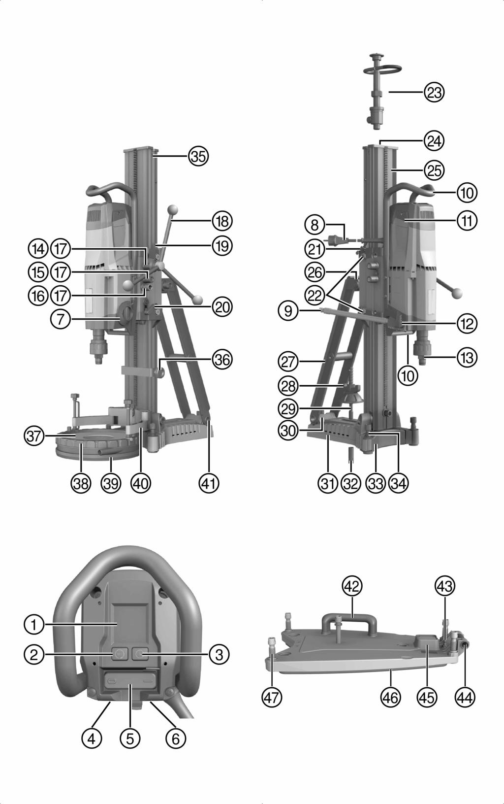
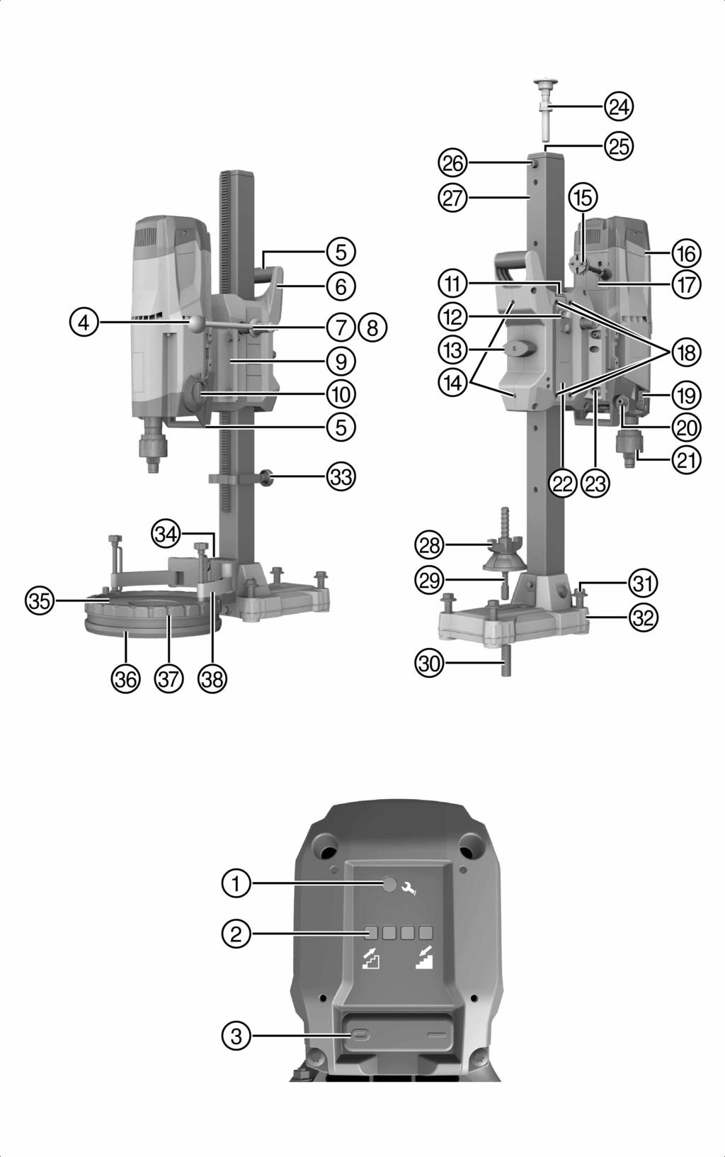
12 Wear hearing protection when diamond drilling. Exposure to noise can cause hearing loss. When the bit is jammed, stop applying downward pressure and turn off the tool. Investigate and take corrective actions to eliminate the cause of the bit jamming. When restarting a diamond drill in the workpiece check that the bit rotates freely before starting. If the bit is jammed, it may not start, may overload the tool, or may cause the diamond drill to release from the workpiece. When securing the drill stand with anchors and fasteners to the workpiece, ensure that the anchoring used is capable of holding and restraining the machine during use. If the workpiece is weak or porous, the anchor may pull out causing the drill stand to release from the workpiece. When securing the drill stand with a vacuum pad to the workpiece, install the pad on a smooth, clean, non-porous surface. Do not secure to laminated surfaces such as tiles and composite coating. If the workpiece is not smooth, flat or well affixed, the pad may pull away from the workpiece. Ensure there is sufficient vacuum before and during drilling. If the vacuum is insufficient, the pad may release from the workpiece. Never perform drilling with the machine secured by the vacuum pad only, except when drilling downwards. If the vacuum is lost, the pad will release from the workpiece. When drilling through walls or ceilings, ensure to protect persons and the work area on the other side. The bit may extend through the hole or the core may fall out on the other side. When drilling overhead, always use the liquid collection device specified in the instructions. Do not allow water to flow into the tool. Water entering the power tool will increase the risk of electric shock Additional safety precautions Personal safety Tampering with or modification of the machine is not permitted. The machine is not intended for use by inexperienced persons who have received no special training. Keep the machine out of reach of children. Avoid touching rotating parts. Switch the machine on only after it is in position at the workpiece. Touching rotating parts, especially rotating accessory tools, may lead to injury. Avoid skin contact with drilling slurry. Dust from materials, such as paint containing lead, some kinds of wood, concrete / masonry / stone containing silica, and minerals as well as metal, may be injurious to health. Contact with or inhalation of the dust may cause allergic reactions and/or respiratory or other diseases to the operator or bystanders. Certain kinds of dust are classified as carcinogenic such as oak and beech dust, especially in conjunction with additives for wood conditioning (chromate, wood preservative). Material containing asbestos must only be handled by specialists. Use a dust removal system that is as effective as possible. Accordingly, use a suitable vacuum cleaner of the type recommended by Hilti for wood dust and/or mineral dust and which is designed for use with this power tool. Ensure that the workplace is well ventilated. The use of a dust mask suitable for the particular type of dust is recommended. Observe national regulations applicable to the materials on which you intend to use the machine. The diamond core drilling machine and the diamond core bit are heavy pieces of equipment. There is a risk of crushing parts of the body. The user and any other persons in the vicinity must wear suitable eye protection, a hard hat, ear protection, protective gloves and safety footwear while the machine is in use. Careful handling and use of electric tools Make sure that the machine is correctly fastened in the drill stand. Take care to ensure that an end stop is always fitted to the drill stand. The safety-relevant end-stop function becomes inoperative if this component is not fitted. Ensure that the accessory tools used have a mounting system that is compatible with the drilling machine and that they are secured in the chuck correctly. Electrical safety Avoid using extension cords with multiple power outlets and the simultaneous use of several machines connected to one extension cord. The machine may be operated only when connected to an adequately-rated power supply equipped with an earth (ground) conductor. Before beginning work, check the working area (e.g. using a metal detector) to ensure that no concealed electric cables or gas and water pipes are present. External metal parts of the machine 5
13 may become live, for example, when an electric power line is damaged accidentally. This presents a serious risk of electric shock. Make sure that the supply cord is not pinched and damaged as the carriage advances. Never operate the machine without the accompanying PRCD (machines without PRCD: Never operate the machine without an isolating transformer). Test the PRCD each time before use. Check the machine s supply cord at regular intervals and have it replaced by a qualified specialist if found to be damaged. If the machine s supply cord is damaged it must be replaced with a specially-prepared and approved supply cord available from Hilti Customer Service. Check extension cords at regular intervals and replace them if found to be damaged. Do not touch the supply cord or extension cord if it is damaged while working. Disconnect the supply cord plug from the power outlet. Damaged supply cords or extension cords present a risk of electric shock. Never operate the machine when it is dirty or wet. Dust (especially dust from conductive materials) or dampness adhering to the surface of the machine may, under unfavorable conditions, lead to electric shock. Dirty or dusty machines should thus be checked by Hilti Service at regular intervals, especially if used frequently for working on conductive materials. Workplace Approval must be obtained from the site engineer or architect prior to beginning drilling work. Drilling work on buildings and other structures may influence the static equilibrium of the structure, especially when steel reinforcing bars or load-bearing components are cut through. If the drill stand has not been fastened correctly, always move the machine mounted on the drill stand all the way down in order to prevent the stand from falling over. Keep the supply cord, extension cord, water hose and vacuum hose away from rotating parts of the machine. Use of the water collection system in conjunction with a wet-type industrial vacuum cleaner is a mandatory requirement for wet drilling overhead. Use of the vacuum securing method without an additional means of fastening is prohibited for drilling in an upward direction. An additional means of securing the drill stand must be employed when the machine is secured with the vacuum securing method (accessory) for horizontal drilling. 3 Description 3.1 Parts, indicators and operating controls for diamond core drilling machine DD 250/drill stand DD HD 30 1 Diamond core drilling machine DD Multifunction display ; Button for hole-starting mode = Runtime counter button % Rating plate & On/Off switch ( Supply cord cover ) Gear selector + / : $ Supply cord with PRCD Water connection Carrying handle (2x) Carbon brush cover (2x) Water flow regulator Chuck Carriage DD-HD 30 Hand wheel shaft 1:1 Hand wheel shaft 1:3 Eccentric pin (lock for the diamond core drilling machine) Q Shear pin (5x) W E R T Z Hand wheel Leveling indicator (2x) Carriage lock Supply cord guide Carriage play adjusting screw (4x) Drill stand DD-HD 30 U Threaded spindle (accessory) I Cover O Rail P Carrying handle Ü Brace [ Clamping nut ] Clamping spindle Æ º ~ A S D F Rating plate Base plate Anchor Hole center indicator Leveling screw (3x) End stop screw Depth gage (accessory) 6
14 G H Sealing washer for water collector (accessory) Water collector (accessory) Vacuum base plate (accessory) Ö Vacuum release valve Ä Vacuum hose connector Traversing mechanism adapter J K L Seal (accessory) Water collector holder (accessory) Traversing mechanism adapter Œ Å ª Pressure gage Vacuum seal Leveling screw (4x) 3.2 Parts, indicators and operating controls for diamond core drilling machine DD 200/drill stand DD ST Diamond core drilling machine DD Service indicator ; Drilling performance indicator = On/Off switch % Hand wheel & Carrying handles (2x) ( Carriage casing ) Hand wheel shaft + Shear pin (2x) Intermediate piece / Gear selector : Adjusting screw hexagon socket wrench Supply cord guide DD ST 200 drill stand I Threaded spindle (accessory) O Threaded spindle chuck P End stop screw Ü Rail [ Clamping nut ] Clamping spindle Æ Anchor º Leveling screw (4x) $ Q W E R T Z U ~ A S D F G H Carriage lock Screw for adjusting the play between carriage and roller (2x) Supply cord with PRCD Carbon brush cover (2x) Supply cord cover Screw for adjusting the play between carriage and sliding piece (4x) Water flow regulator Water connection Chuck Rating plate Intermediate piece screw (4x) Base plate Depth gage (accessory) Spacer for water collector holder (accessory) Sealing washer for water collector (accessory) Seal (accessory) Water collector (accessory) Water collector holder (accessory) 3.3 Intended use The product described is an electrically powered diamond core drilling machine. It is designed for drilling through-holes and blind holes in (reinforced) mineral base materials using a drill stand and the wet drilling technique. Hand-held use of the diamond core drilling machine is not permitted. The product described is designed for professional use and may be operated, serviced and maintained only by trained, authorized personnel. This personnel must be informed of any particular hazards that may be encountered. The product described and its ancillary equipment may present hazards when used incorrectly by untrained personnel or when used not as directed. Always use a drill stand when using the diamond core drilling machine. The drill stand must be sufficiently anchored in the base material by an anchor or vacuum base plate. Do not use a hammer or other heavy object when making adjustments to the base plate. The tool may be operated only when connected to a power supply providing a voltage and frequency in compliance with the information given on its rating plate. Observe the national health and safety requirements. Observe the safety rules and operating instructions for the accessories used. To reduce the risk of injury, use only genuine Hilti core bits and accessories. 3.4 DD 250: Display symbols and explanations on the multifunction display of the diamond core drilling machine For the following indicators, the diamond core drilling machine must be ready for operation (plugged in and with a switched-on PRCD). 7


15 The status bar displays various pieces of information regarding the machine s current status, such as the gear engaged or the activated holestarting mode. Status bar for information Status bar for warning messages Spirit level Gear indicator for first to fourth gear Hole-starting mode is active The hole-starting mode cannot be activated The status bar displays various warning indicators that do not cause the diamond core drilling machine to stop immediately, such as (from right to left) time remaining until the carbon brushes have to be replaced, when service is necessary or if there is a fault in the power supply. The diamond core drilling machine is not switched on. The indicator helps level the system and align the drill stand when drilling at an angle. The indicator displays the alignment of the diamond core drilling machine symbolically and in degrees. Angular accuracy at room temperature: ±2 The diamond core drilling machine is running under no load. The indicator helps ensure that the gear engaged is suitable for the diamond core bit used. At the top left, the indicator displays the gear engaged and in the center, the recommended core bit diameter range in millimeters and inches for this gear. The diamond core drilling machine is switched off or running under no load. The function makes it possible to start holes with low vibration in the case of core bits with a large diameter. This function can be deactivated at any time by pressing the button for the hole-starting mode again The indicator is automatically hidden after a few seconds. The diamond core drilling machine is drilling. The button for activating hole-starting mode was pressed while the diamond core drilling machine was under load, was being run-in after the carbon brushes had been changed, or was in cool-down mode, or immediately after the diamond core drilling machine had been operated for two minutes in hole-starting mode. Activation is not possible. The indicator is automatically hidden after a few seconds. The diamond core drilling machine is drilling. The hole-starting mode is active. The indicator displays the time remaining until the diamond core drilling machine automatically switches off. Running time for the holestarting mode To protect the diamond core drilling machine, the hole-starting mode automatically switches off after a maximum of two minutes. 8


 in hours, minutes and seconds. Press the button for the runtime counter for a few seconds to reset the drilling time total to zero.")
16 The diamond core drilling machine is drilling. The hole-starting mode is not active. The indicator helps ensure that the diamond core drilling machine is being operated in the optimal range. Background color: Yellow. The contact pressure is too low. Increase the contact pressure. Drilling performance indicator: Contact pressure is too low Drilling performance indicator: Optimum contact pressure Rated current limit has been exceeded Drilling performance indicator: Contact pressure is too high Runtime counter The diamond core drilling machine is drilling. The hole-starting mode is not active. The indicator helps ensure that the diamond core drilling machine is being operated in the optimal range. Background color: Green. The contact pressure is at the optimum level. The diamond core drilling machine is drilling. The hole-starting mode is not active. It is indicated that rated current has exceeded the limit of 20 A. Background color: Green. The contact pressure is too high. Reduce the contact pressure. The diamond core drilling machine is drilling. The hole-starting mode is not active. The indicator helps ensure that the diamond core drilling machine is being operated in the optimal range. Background color: Red. The contact pressure is too high. Reduce the contact pressure. The button for the runtime counter has been pressed. At the top, the indicator displays the drilling time (the diamond core drilling machine is drilling) and, at the bottom, the diamond core drilling machine's operating hours (diamond core drilling machine is switched on) in hours, minutes and seconds. Press the button for the runtime counter for a few seconds to reset the drilling time total to zero. The indicator is automatically hidden after a few seconds or by pressing the button again. The diamond core drilling machine is running. The carbon brush wear limit has almost been reached. The indicator helps ensure that the carbon brushes are replaced in good time. The time remaining until the diamond core drilling machine automatically switches off is displayed in hours and minutes. The indicator is automatically hidden after a few seconds. Time remaining until the carbon brushes are to be replaced The carbon brushes are worn. The carbon brushes must be replaced. An internal fault has occurred. Service indicator 9
17 The diamond core drilling machine is running. The carbon brushes have been changed and must be run in by letting the machine run under no load for at least one minute without interruption, in order to achieve the optimum service life. The indicator displays the time remaining until the running-in process is completed. Running in after the carbon brushes have been replaced Overheating The diamond core drilling machine has overheated. It is no longer running or is in cool-down mode. The indicator displays the time remaining until the diamond core drilling machine cools down. If the diamond core drilling machine is still too hot after this time has elapsed, the remaining running time starts from the beginning again. Undervoltage occurred in the supply network. In the event of undervoltage, the diamond core drilling machine cannot be operated at full power. The indicator is automatically hidden after a few seconds. Fault in the power supply Maximum running time with hole-starting mode active has been exceeded; Fault in the power supply; The diamond core drilling machine has been overloaded; Overheated, water has entered the motor or the cooling running time has ended. Restart interlock 3.5 DD 200: Service indicator and drilling performance indicator The diamond core drilling machine is equipped with a service indicator and an LED drilling performance indicator. For the following indicators, the diamond core drilling machine must be ready for operation (plugged in and with a switched-on PRCD). Status Lights up red Meaning 10 The diamond core drilling machine is in working order. The carbon brush wear limit has almost been reached. The indicator helps ensure that the carbon brushes are replaced in good time. After the lamp lights up for the first time, the machine may continue to be used for several hours before the automatic cut-out is activated. The diamond core drilling machine is in working order. The carbon brushes have been changed and must be run in by letting the machine run under no load for at least one minute without interruption, in order to achieve the optimum service life. The diamond core drilling machine is no longer in working order. The carbon brushes are worn. The carbon brushes must be replaced. The diamond core drilling machine is no longer in working order. Damage to the diamond core drilling machine.


18 Status Flashing red light Meaning Overheating. See Troubleshooting. The LED on the left lights yellow. Contact pressure is too low. The LEDs in the middle light green. The contact pressure is at the optimum level. The LED on the right lights red. Contact pressure is too high. LED on the right-hand side flashes red Contact pressure is too high. The rated current limit has been exceeded. 3.6 Items supplied To help ensure safe and reliable operation, use only genuine Hilti spare parts and consumables. Spare parts, consumables and accessories approved by Hilti for use with the product can be found at your local Hilti Center or online at: Items supplied: DD 250/DD 200 for DD HD 30 Diamond core drilling machine, operating instructions. Items supplied: DD 200 for DD ST 200 Diamond core drilling machine, hand wheel/lever, hexagon socket wrench, operating instructions. 3.7 Accessories and spare parts QR codes Scan the applicable QR code with your smartphone for further information. DD 200 for drill standdd-hd 30 DD 200 for drill standdd-st

19 DD 250 for drill standdd-hd 30 Spare parts Item number Designation Hose connector Carbon brushes V Carbon brushes V 4 Technical data 4.1 Diamond core drilling machine When powered by a generator or transformer, the generator or transformer s power output must be at least twice the rated input power shown on the rating plate of the power tool. The operating voltage of the transformer or generator must always be within +5% and -15% of the rated voltage of the power tool. The information given applies to a rated voltage of 230 V. The data may vary in the event of deviations from the rated voltage and for country-specific versions. Please refer to the power tool s rating plate for details of its voltage, frequency, current and input power ratings. Information for users as per EN : Switching on causes a brief drop in voltage. Other appliances may be negatively affected on mains supplies where conditions are unfavorable. No malfunctions are to be expected in mains supplies with an impedance of less than ohms. DD 250 Weight in accordance with EPTA procedure 01/ kg DD 200 for DD HD 30 DD 200 for DD ST kg 20.4 kg DD-HD kg 21.4 kg / DD ST 200 / / 12.3 kg Drilling depth without extension 500 mm 500 mm 500 mm Rated speed under no load 240 rpm 240 rpm 240 rpm Weight of the drill stand in accordance with EPTA procedure 01/2003 Permissible water supply pressure 1st gear 2nd gear 3rd gear Optimum core bit diameter 4th gear 1st gear 2nd gear 3rd gear 4th gear Ideal distance between the marking on the anchor base plate and the hole center Ideal distance between the marking on the vacuum base plate and the hole center 12 6 bar 580 rpm 1,160 rpm 2,220 rpm 152 mm 450 mm 82 mm 152 mm 35 mm 82 mm 12 mm 35 mm 330 mm 165 mm 6 bar 580 rpm 1,160 rpm / 152 mm 500 mm 82 mm 152 mm 35 mm 82 mm / 330 mm 165 mm 6 bar 580 rpm 1,160 rpm / 152 mm 500 mm 82 mm 152 mm 35 mm 82 mm / 380 mm 215 mm
20 4.2 Permissible core bit diameters for various items of equipment The approved drilling directions for the various items of equipment must be observed. Use of a wet/dry vacuum cleaner with a water collection system is mandatory for drilling upwards. Ø without accessories Ø with spacer Ø with water collection system and wettype industrial vacuum cleaner DD 250 DD 200 for DD HD 30 DD 200 for DD ST mm 450 mm 35 mm 500 mm 35 mm 500 mm 12 mm 300 mm 12 mm 250 mm 35 mm 300 mm 35 mm 250 mm 35 mm 400 mm 35 mm 250 mm 4.3 Noise information and vibration values determined in accordance with EN The sound pressure and vibration values given in these instructions have been measured in accordance with a standardized test and may be used to compare one power tool with another. They may be used for a preliminary assessment of exposure. The data given represents the main applications of the power tool. However, if the power tool is used for different applications, with different accessory tools, or is poorly maintained, the data may vary. This may significantly increase exposure over the total working period. An accurate estimation of exposure should also take into account the times when the power tool is switched off, or when it is running but not actually being used for a job. This may significantly reduce exposure over the total working period. Identify additional safety measures to protect the operator from the effects of noise and/or vibration, for example: maintain the tool and the accessories, keep the hands warm, organization of work patterns. Noise emission values determined in accordance with EN Sound (power) level (LWA) 109 db(a) Sound pressure level (LpA) 93 db(a) Uncertainty for the sound power level (KWA) Uncertainty for the sound pressure level (KpA) 3 db(a) 3 db(a) Total vibration (vector sum of three directions), measured in accordance with EN Triaxial total vibration (vector sum of vibration) at the hand wheel (star handle) does not exceed 2.5 m/s² (including uncertainty K) in accordance with EN Operation 5.1 DD-HD 30: Setting up the drill stand and setting the drilling angle 3 CAUTION Risk of injury Risk of crushing parts of the body. Releasing the tilt mechanism on the drill stand may cause the rail to tilt suddenly. Exercise caution. Wear protective gloves. CAUTION Risk of injury Hazard presented by a falling diamond core drilling machine. Always fit the cover at the end of the rail. The cover provides protection and acts as an end stop. 1. Loosen the screw at the pivoting joint at the bottom end of the rail and the screw at the top end of the brace. 2. Adjust the rail to the desired angle. The angle scale at the rear serves as an adjustment aid. 3. Retighten the two screws securely. 13
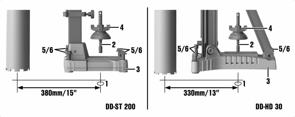
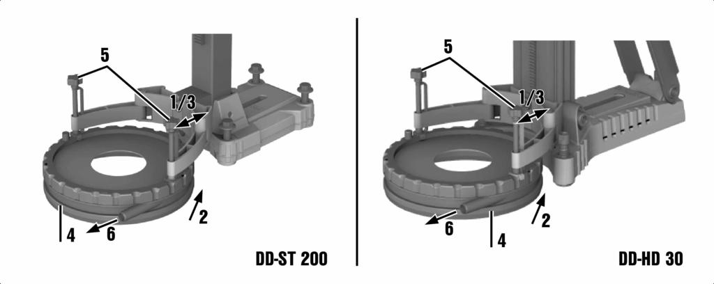
21 5.2 DD-HD 30: Locking the carriage on the drill stand 1. Pivot the carriage lock in the locked position. The locking pin must engage in this position. 2. Slightly turn the hand wheel to ensure that the carriage is securely locked. 5.3 Fitting the hand wheel on the drill stand 4 The hand wheel may be fitted on the left-hand or on the right-hand side of the carriage. In the case of the DD HD 30 drill stand, the hand wheel may be fitted on the carriage on two different axes. The upper axis directly affects the carriage drive and the lower axis affects the carriage drive with a gear reduction of 1:3. 1. Pull the black ring back to fit the hand wheel. 2. Fit the hand wheel onto the axle. 5.4 Fastening the drill stand with an anchor 5 WARNING Risk of injury The tool may become detached and cause damage if the wrong anchor is used. Use an anchor suitable for the base material on which you are working and observe the anchor manufacturer s instructions. Please contact Hilti Technical Service if you have any questions about secure fastening. Hilti metal expansion anchors M16 (5/8") are usually suitable for fastening diamond core drilling equipment to uncracked concrete. Under certain conditions, however, it may be necessary to use an alternative fastening method. Please contact Hilti Technical Service if you have any questions about secure fastening. 1. Fit the anchor that is suitable for the corresponding base material. Select the distance according to the base plate used. Ideal distance from the hole center for DD-HD 30: 330 mm (13 in) Ideal distance from the hole center for DD-ST 200: 380 mm (15 in) 2. Screw the clamping spindle (accessory) into the anchor. 3. Place the drill stand over the spindle and align it. When using the DD-HD 30 drill stand, use the hole center indicator to help you align the drill stand. When a spacer is used, the drill stand cannot be aligned using the hole center indicator. 4. Screw the clamping nut onto the spindle but do not tighten it. 5. Level the base plate by turning the leveling screws. Use the leveling indicators for this purpose. Take care to ensure that the leveling screws make firm contact with the underlying surface. 6. Tighten the leveling screws evenly until the drill stand is securely fastened. 7. Make sure that the drill stand is fastened securely. 5.5 Fastening the drill stand with the vacuum base plate (accessory) 6 DANGER Risk of injury Hazard presented by a falling diamond core drilling machine. Fastening the drill stand to the ceiling only by means of the vacuum securing method is not permissible. A heavy structural support or a threaded spindle, for example, can serve as an additional means of fastening. 14
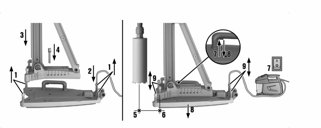
22 WARNING Risk of injury Hazard presented by a falling diamond core drilling machine. When drilling horizontally, the drill stand must be secured additionally by a chain. WARNING Risk of injury Pressure check Before beginning drilling and during operation, it must be ensured that the pressure gage indicator remains within the green area. Make sure that the anchor base plate lies flat against the vacuum base plate and that the two plates are securely connected when using the drill stand with an anchor base plate. Screw the anchor base plate securely onto the vacuum base plate. Make sure that the core bit selected for use will not damage the vacuum base plate. Before positioning the drill stand, ensure that there is sufficient space available for assembly and operation. Use the vacuum fastening method only together with core bits of up to 300 mm (12") in diameter and when no spacer is fitted. A vacuum release valve, which can be used to increase the vacuum again, is fitted to the hand grip on the vacuum base plate. 1. Turn all leveling screws back until they project approximately 5 mm (1/5 in) beneath the vacuum base plate. 2. Connect the vacuum connector on the vacuum base plate to the vacuum pump. 3. Place the drill stand on the vacuum base plate. 4. Fit the drill stand using the screw supplied with a washer underneath on the vacuum base plate and tighten the screw. DD-HD 30: Use the thinner of the two washers supplied. DD-ST 200: Use the thicker of the two washers supplied. 5. Locate the center point of the hole to be drilled. Draw a line from the center of the hole to be drilled towards where the drill stand is to be positioned. 6. Make a mark on the line at the distance stated from the center of the hole to be drilled. Bring the middle of the front edge of the vacuum base plate into alignment with the mark made. Take care to ensure that the base material on which the vacuum base plate is positioned is flat and clean. Ideal distance from the hole center for DD-HD 30: 165 mm (6 1/2 in) Ideal distance from the hole center for DD-ST 200: 215 mm (8 1/2 in) 7. Switch on the vacuum pump, press the vacuum release valve and keep it pressed. 8. Once the drill stand has been positioned correctly, release the vacuum release valve and press the vacuum base plate against the base material. 9. Level the vacuum base plate by turning the leveling screws. Use the leveling indicators for this purpose. The anchor base plate cannot and should not be leveled on the vacuum base plate. 10. Make sure that the drill stand is fastened securely. 5.6 DD-HD 30: Fastening the drill stand with the threaded spindle (accessory) Remove the cover (with built-in end stop) from the top end of the rail. Fit the cylindrical connector on the threaded spindle into the end of the rail on the drill stand. Secure the threaded spindle by turning the eccentric pin. Position the drill stand on the work surface. 15
23 5. Level the base plate by turning the leveling screws. 6. Secure the drill stand with the threaded spindle and tighten the threaded spindle. 7. Make sure that the drill stand is fastened securely. 5.7 DD ST 200: Fastening the drill stand with the threaded spindle (accessory) Fasten the threaded spindle at the upper end of the rail. Position the drill stand on the work surface. Level the base plate by turning the leveling screws. Secure the drill stand with the threaded spindle and tighten the threaded spindle. Make sure that the drill stand is fastened securely. 5.8 DD-HD 30: Extending the rail (accessory) on the drill stand 7 When starting holes, use only core bits or extended core bits with a maximum total length of 650 mm (25 1/2 in). A depth gage on the rail can be used as an additional end stop. After removing the extension rail, the cover (with integrated end stop) must be refitted to the drill stand in order to ensure that the safety-relevant end-stop function is restored. The safety-relevant end-stop function becomes inoperative if this component is not fitted. 1. Remove the cover (with built-in end stop) from the top end of the rail. Fit the cover on the extension rail. 2. Fit the cylindrical connector on the extension rail into the end of the rail on the drill stand. 3. Secure the extension rail by turning the eccentric pin. 5.9 DD-HD 30: Fitting the spacer (accessory) 8 WARNING Risk of injury. The fastening may become overloaded. When one or more spacers are used, the contact pressure must be reduced in order to avoid overloading the fastening. The diamond core drilling machine should not already be mounted on the drill stand when the spacer is being fitted. When core bits with a diameter of 300 mm (11 1/2 in) or greater are used, the distance between the drill stand and the drilling axis must be increased by fitting one or two spacers. The hole center indicator is no longer functional when spacers are used Lock the carriage on the rail with the carriage lock. Pull out the eccentric pin for locking the diamond core drilling machine on the carriage. Place the spacer into the carriage. Push the eccentric pin into the carriage as far as it will go. Tighten the eccentric pin. Check to ensure that the spacer is securely fastened DD ST 200: Fitting the spacer (accessory) 9 WARNING Risk of injury. The fastening may become overloaded. When one or more spacers are used, the contact pressure must be reduced in order to avoid overloading the fastening. 16
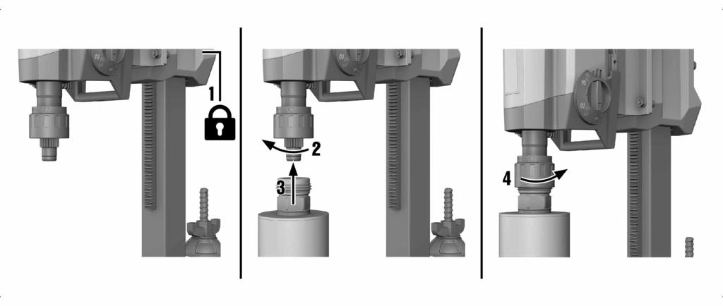
24 When core bits with a diameter of 400 mm (15 3/4 in) or greater are used, the distance between the drill stand and the drilling axis must be increased by fitting a spacer. 1. Detach the diamond core drilling machine from the drill stand. 2. Separate the carriage from the diamond core drilling machine by loosening the four screws on the carriage. 3. Screw the spacer tightly to the carriage with the four screws that are additionally supplied. 4. Re-screw the diamond core drilling machine tightly to the spacer with the four screws DD-HD 30: Attaching the diamond core drilling machine to the drill stand 8 CAUTION Risk of injury Hazard presented by inadvertent starting of the diamond core drilling machine The diamond core drilling machine should not be connected to the power supply during set-up. Lock the carriage on the rail with the carriage lock. Pull out the eccentric pin for locking the diamond core drilling machine on the carriage. Fit the diamond core drilling machine onto the carriage or the spacer. Push the eccentric pin into the carriage or the spacer as far as it will go. Tighten the eccentric pin. Fasten the supply cord in the cord guide to the carriage cover. Check to ensure that the diamond core drilling machine is securely fastened to the drill stand DD ST 200: Attaching the diamond core drilling machine to the drill stand 10 DANGER Risk of injury Impact as a result of a fast-moving lever or hand wheel when the carriage is in motion. The lever and the hand wheel must not be fitted on the drill stand when the diamond core drilling machine is being fitted. CAUTION Risk of injury Hazard presented by inadvertent starting of the diamond core drilling machine. The diamond core drilling machine should not be connected to the power supply during set-up. The drive unit and the carriage form a unit. The diamond core drilling machine can thus be removed from the drill stand together with the carriage. Adjust the play between the rail and carriage before using the tool for the first time. 1. Remove the end stop screw from the end of the rail. 2. Ensure that the carriage lock is open. 3. Mount the diamond core drilling machine on the drill stand by sliding the opening in the carriage over the end of the rail. 4. Lock the carriage on the rail by turning the carriage lock through Slightly turn the hand wheel to ensure that the diamond core drilling machine is securely fastened. 6. Refit the end stop screw to the end of the rail. The safety-relevant end-stop function becomes inoperative if this component is not fitted. 17
25 5.13 Fitting the water connection (accessory) CAUTION Risk of personal injury and material damage The hose may become damaged if it is used incorrectly. Regularly check the hoses for damage and make sure that the maximum permissible water supply pressure of 6 bar is not exceeded. Make sure that the hose does not come into contact with rotating parts. Make sure that the hose is not damaged as the carriage advances. Maximum water temperature: 40 C. Check the water supply system to ensure there are no leaks. To avoid damage to the components, use only fresh water containing no dirt particles. A flow meter (accessory) may be fitted between the tool and the water supply hose. 1. Connect the water flow regulator to the diamond core drilling machine. 2. Connect the water supply (hose connection) Fitting the water collection system (accessory) 11 WARNING Risk of personal injury and material damage The diamond core drilling machine may become damaged and the risk of electric shock is increased. Water must not be allowed to run over the motor and cover. Use of a wet-type industrial vacuum cleaner is a mandatory requirement for drilling in an upwards direction. The diamond core drilling machine must be at a 90 angle to the ceiling. The water collection system sealing disc must match the diamond core bit diameter. Use of the water collection system allows water to be led away under control, thus preventing the surrounding area from being heavily soiled. The best results are achieved with a wet-type industrial vacuum cleaner. When using the drill stand DD ST 200: Before fitting the water collector holder, screw the spacer for the water collector holder tightly to the drill stand Loosen the screw on the front of the drill stand at the bottom end of the rail. Slide the water collector holder into position under the screw from below. Tighten the screw securely. Position the water collector, with seal and water collector sealing disc fitted, between the two movable arms of the holder. 5. Secure the water collector to the holder with the two screws. 6. Connect a wet-type industrial vacuum cleaner to the water collector or establish a hose connection through which the water can drain away Setting the depth gage (accessory) 1. Turn the hand wheel until the core bit is in contact with the base material. 2. Set the desired drilling depth by adjusting the distance of the depth gage from the carriage. 3. Lock the depth gage in position. 18
26 5.16 Fitting the diamond core bit (BL chuck) 12 DANGER Risk of injury Fragments of the workpiece or of broken insert tools may be ejected and cause injury beyond the immediate area of operation. Do not use damaged insert tools. Check the insert tools for chipping, cracks, or heavy wear each time before use. CAUTION Risk of injury The tool becomes hot as a result of use. It may have sharp edges. Wear protective gloves when changing the tool. Diamond core bits must be replaced when the cutting performance and/or rate of drilling progress drops significantly. This generally is the case when the diamond segments reach a height of less than 2 mm (1/16 in). 1. Lock the carriage on the rail with the carriage lock. Check to ensure that it is securely fastened. 2. Open the chuck by turning it in the direction of the "Open brackets" symbol. 3. From below, push the connection end of the diamond core bit into the chuck on the diamond core drilling machine, making sure that the teeth engage. 4. Close the chuck by turning it in the direction of the "Closed brackets" symbol. 5. Check that the diamond core bit is seated securely in the chuck Fitting the diamond core bit with an alternative type of chuck 1. Lock the drive spindle with a suitable open-end wrench. 2. Tighten the core bit with a suitable open-end wrench Selecting the speed 13 Press the switch only when the tool is stationary. 1. Select the switch setting according to the core bit diameter used. 2. When turning the switch, rotate the core bit by hand at the same time until the switch can be set in the recommended position PRCD ground fault circuit interrupter 1. Plug the diamond core drilling machine s mains plug into an earthed/grounded power outlet. 2. Press the "I" or "RESET" button on the PRCD ground fault circuit interrupter. The indicator lights up. 3. Press the "0" or "TEST" button on the PRCD ground fault circuit interrupter. The indicator goes out. WARNING Risk of injury Risk of electric shock. If the indicator continues to light up, further operation of the diamond core drilling machine is not permissible. Have your diamond core drilling machine repaired by Hilti Service. 4. Press the "I" or "RESET" button on the PRCD ground fault circuit interrupter. The indicator lights up. 19
27 5.20 Operating the diamond core drilling machine WARNING Risk of personal injury and material damage The diamond core drilling machine may become damaged and the risk of electric shock is increased. Use of the water collection system in conjunction with a wet-type industrial vacuum cleaner is a mandatory requirement for wet drilling overhead. DANGER Risk of personal injury and material damage The wet-type industrial vacuum cleaner switches on and off with a delay. This allows water to run over the diamond core drilling machine. The diamond core drilling machine may become damaged and the risk of electric shock is increased. When drilling in an upward direction, the wet-type industrial vacuum cleaner must be switched on manually before opening the water supply valve and switched off again manually after closing the water supply valve. DANGER Risk of personal injury and material damage The diamond core drilling machine may become damaged and the risk of electric shock is increased. When drilling in an upward direction, stop working if the suction removal system stops working (e.g. the wet-type industrial vacuum cleaner is full). WARNING Risk of personal injury and material damage The water collector cannot function correctly during drilling in an upward direction at an angle. The diamond core drilling machine may become damaged and the risk of electric shock is increased. Do not drill in an upward direction at an angle. DD 250: Pressing the button for the hole-starting mode (when the machine is idling or operating under no load) reduces the speed for starting holes. This makes it possible for diamond core bits of large diameters to start holes with greater ease and less vibration. Pressing the button for the hole-starting mode again deactivates this function and the diamond core drilling machine adjusts up to the preset speed. If the function for starting holes is not deactivated before a maximum of two minutes has expired, the diamond core drilling machine automatically switches off Slowly open the water flow regulator until the desired volume of water is flowing. Press the On/Off switch on the diamond core drilling machine to "I". Release the carriage locking mechanism. Turn the hand wheel until the core bit is in contact with the base material. When beginning drilling, apply only light pressure, until the core bit has centered itself. Only increase the pressure afterwards. 6. Regulate the contact pressure while observing the drilling performance indicator Switching off the diamond core drilling machine WARNING Risk of personal injury and material damage The diamond core bit fills with water during overhead drilling. The diamond core drilling machine may become damaged and the risk of electric shock is increased. As a first step, carefully allow the water to drain away after completing overhead drilling. This is done by disconnecting the water supply from the water flow regulator and draining the water by opening the water flow regulator. Do not allow the water to run over the motor and cover. 1. Connect the water flow regulator to the diamond core drilling machine. 20
28 Remove the diamond core bit from the hole. Switch off the diamond core drilling machine. Lock the carriage on the rail with the carriage lock. Switch off the wet-type industrial vacuum cleaner (if used) DD-HD 30: Detaching the diamond core drilling machine from the drill stand 1. Lock the carriage on the rail with the carriage lock. 2. Remove the supply cord from the cord guide on the carriage cover. CAUTION Risk of personal injury and material damage Hazard presented by a falling diamond core drilling machine Hold the core drilling machine tightly with one hand by the carrying handle. Loosen the eccentric pin for locking the tool on the carriage. Pull out the eccentric pin. Remove the diamond core drilling machine from carriage. Push the eccentric pin into the carriage as far as it will go DD ST 200: Detaching the diamond core drilling machine from the drill stand The drive unit and the carriage form a unit. The diamond core drilling machine can thus be removed from the drill stand together with the carriage Remove the end stop screw from the end of the rail. Release the carriage locking mechanism. Detach the diamond core drilling machine from the drill stand. Refit the end stop screw to the end of the rail. The safety-relevant end-stop function becomes inoperative if this component is not fitted. 6 Care, maintenance, transport and storage 6.1 Care of the product Keep the product, especially its grip surfaces, clean and free from oil and grease. Do not use cleaning agents containing silicone. Never operate the product when the air vents are blocked. Clean the air vents carefully using a dry brush. Do not allow foreign objects to enter the interior of the product. Clean the outside of the tool at regular intervals with a slightly damp cloth. Do not use a spray, steam pressure cleaning equipment or running water for cleaning. Always keep the connection end of the core bit clean and lightly greased. After carrying out care and maintenance, check that all protective and safety devices are fitted and that they function with no defects. If service or repair is required, please contact your salesperson or refer to our contact details at DD-HD 30: Adjusting the play between rail and carriage You can adjust the play between rail and carriage using the four adjusting screws on the carriage. 1. Loosen the adjusting screws using a 5 mm hexagon socket wrench (do not remove the screws). 2. Using a 19 mm open-end wrench, turn the adjusting screws so that the rollers are pressed slightly against the rail. 3. Tighten the adjusting screws firmly. The carriage is correctly adjusted when it remains in position without a diamond core drilling machine fitted and moves down when a drilling machine is mounted. 21
29 6.1.2 DD 200 for the DD-ST 200: Adjusting play between rail and carriage You can adjust the play between rail and carriage using the 6 adjusting screws on the carriage. 1. Use a hexagon socket wrench to tighten the adjusting screws hand-tight. Technical data Tightening torque 3 Nm 2. Then loosen the four adjusting screws at the side by turning them half of a turn and the two rear adjusting screws by turning them quarter of a turn. 3. The carriage is correctly adjusted when it remains in position without a diamond core bit but moves down when a diamond core bit is fitted. 6.2 Replacing the carbon brushes DANGER Risk of injury Risk of electric shock. The machine may be operated, serviced and repaired only by trained, authorized personnel. This personnel must be specially informed of any possible hazards. The indicator with the open-end wrench symbol lights up when the carbon brushes need to be changed. Always change all the carbon brushes at the same time. 1. Disconnect the diamond core drilling machine from the power supply. 2. Open the carbon brush covers on the left-hand and right-hand side of the motor. 3. Take note of how the carbon brushes are fitted and how the conductors are positioned. Remove the worn carbon brushes from the diamond core drilling machine. 4. Fit the new carbon brushes so that they are positioned exactly the same as the old ones fitted previously. Take care to avoid damaging the insulation on the indicator lead as you insert the brushes. 5. Screw on the carbon brush covers on the left- and right-hand side of the motor. 6. Run in the carbon brushes by letting the machine run under no load for at least one minute without interruption. After replacing the carbon brushes, the indicator lamp will go out after the machine has run for approx. one minute. If the minimum running-in time of one minute is not observed, the life of the carbon brushes will be greatly reduced. 6.3 Transport and storage CAUTION Risk of personal injury and material damage Frost-damaged components may cause the tool to stop working and present a risk of injury for the user. When temperatures drop below zero, check to ensure that no water remains in the power tool. WARNING Risk of injury Individual parts may become detached and fall off. Do not lift the diamond core drilling machine and/or the drill stand by crane. 22
30 Transport the diamond core drilling machine, the drill stand and the core bit as separate units. Use the wheel assembly (accessory) as an aid when transporting the equipment. Open the water flow regulator before putting the diamond core drilling machine into storage. 7 Troubleshooting If the trouble you are experiencing is not listed in this table or you are unable to remedy the problem by yourself, please contact Hilti Service. 7.1 DD 200: The diamond core drilling machine is not in working order Malfunction Possible cause The PRCD isn t switched on. Interruption in the electric supply. The service indicator shows nothing. The service indicator lights. Action to be taken Check that the PRCD is functioning and switch it on. Plug in another electric tool or appliance and check whether it works. Check the plug connections, supply cord, power supply line and main supply fuse. Water in the motor. The carbon brushes are worn out. Replace the carbon brushes. page 22 The motor has overheated. Wait a few minutes until the motor has cooled down or allow the diamond core drilling machine to run under no load in order to speed up the cooling process. Switch the diamond core drilling machine off and then on again. The service indicator blinks. Allow the diamond core drilling machine to dry out completely in a warm, dry place. 7.2 DD 200: The diamond core drilling machine is in working order Malfunction Possible cause The motor has overheated. The diamond core drilling machine is running in cooling mode. Action to be taken The service indicator blinks. The service indicator lights. The carbon brush wear limit has almost been reached. The diamond core drilling machine will continue to run for a few hours until it shuts down automatically. Wait a few minutes until the motor has cooled down or allow the diamond core drilling machine to run under no load in order to speed up the cooling process. When normal temperature is reached the indication in the display goes out and the diamond core drilling machine activates the restart interlock. Switch the diamond core drilling machine off and then on again. Have the carbon brushes replaced at the next opportunity. 23
31 Malfunction The service indicator lights. Possible cause The carbon brushes have been changed and must be run in. Communication error between the motor electronics and LED indicator. The drilling performance indicator does not light up. The diamond core drilling machine doesn t achieve full performance. Action to be taken Run in the carbon brushes by letting the machine run under no load for at least 1 minute without interruption. The diamond core drilling machine is capable of working even without LED indicator. Bring the diamond core drilling machine to Hilti at your earliest convenience. Supply network fault undervoltage occurred. The diamond core bit doesn t rotate. The diamond core bit has become jammed in the base material. The gear selector isn t engaged. The drilling speed is decreasing. Maximum drilling depth has been reached. The core is stuck in the diamond core bit. Wrong core bit specification for the base material. High steel content (indicated by clear water containing metal cuttings). Stand-guided drilling Turn the handwheel and try to release the diamond core bit by moving the carriage up and down. Operate the gear selector until it engages. Remove the core and use a core bit extension. Remove the core. Select a more suitable diamond core bit specification. Select a more suitable diamond core bit specification. The diamond core bit is defective. Wrong gear selected. Check the diamond core bit for damage and replace it if necessary. The machine has too little power. Use an open-end wrench to release the diamond core bit: Disconnect the supply cord plug from the power outlet. Grip the diamond core bit with a suitable open-end wrench close to the connection end and release the diamond core bit by rotating it. Contact pressure is too low. 24 Check whether other power consumers are disrupting the supply from the network or generator. Check the length of the extension cord used. The diamond core bit is polished. The water flow rate is too high. Select the right gear. Increase the contact pressure. Select the next lower gear. Sharpen the diamond core bit by drilling into a sharpening plate. Reduce the water flow rate by adjusting the water flow regulator.
32 Malfunction The drilling speed is decreasing. Possible cause The water flow rate is too low. Action to be taken Check the water supply to the diamond core bit or, respectively, increase the water flow by adjusting the water flow regulator. The carriage lock is engaged. The shear pin is broken. Replace the shear pin. The diamond core bit can t be The core bit connection end or fitted into the chuck. chuck is dirty or damaged. Water escapes at the water swivel or gear housing. The water pressure is too high. Clean and grease the connection end and/or the chuck or replace these parts. Water escapes from the chuck during operation. The diamond core bit isn t securely tightened in the chuck. The handwheel can be turned without resistance. The rotary shaft seal is worn out. The core bit connection end / chuck is dirty. No water is flowing. The drilling system has too much play. The seal at the chuck or at the connection end is defective. The water channel is blocked. The diamond core bit isn t securely tightened in the chuck. The core bit connection end / chuck is defective. The connection between the dia mond core drilling machine and the carriage or spacers is loose. The carriage has too much play. Screws / bolts on the drill stand are loose. The drill stand is inadequately fastened. Release the carriage locking mechanism. Reduce the water pressure. Replace the rotary shaft seal. Tighten the diamond core bit securely. Remove the core bit. Rotate the diamond core bit approx. 90 about its own axis. Refit the diamond core bit. Clean and grease the connection end and/or the chuck. Check the seal and replace it if necessary. Increase the water pressure or flush the water channel clear from the opposite direction. Clean the water inlet and outlet aperture. Tighten the diamond core bit securely. Remove the core bit. Rotate the diamond core bit approx. 90 about its own axis. Refit the diamond core bit. Check the connection end and chuck and replace them if necessary. Check the connection and, if necessary, refasten the diamond core drilling machine. Adjust the play between the rail and carriage. Check the security of screws / bolts on the drill stand and tighten them if necessary. Fasten the drill stand more securely. 25
33 7.3 DD 250: The diamond core drilling machine is not in working order Malfunction Possible cause The PRCD isn t switched on. Interruption in the electric supply. The multifunction display is not showing anything. Service required. Action to be taken The carbon brushes are worn out. Replace the carbon brushes. page 22 Water in the motor. Allow the diamond core drilling machine to dry out completely in a warm, dry place. The motor has overheated. The cooling down process is complete. Switch the diamond core drilling machine off and then on again. Restart interlock. Maximum running time with holestarting mode activated exceeded. 26 Plug in another electric tool or appliance and check whether it works. Check the plug connections, supply cord, power supply line and main supply fuse. Water in the motor. Supply network fault the power supply has been interrupted. Overheating. Check that the PRCD is functioning and switch it on. Water in the motor. The motor has overheated. Allow the diamond core drilling machine to dry out completely in a warm, dry place. Check whether other power consumers are disrupting the power supply from the network or generator. Check the length of the extension cord used. Switch the diamond core drilling machine off and then on again. Switch the diamond core drilling machine off and then on again. Allow the diamond core drilling machine to dry out completely in a warm, dry place. Wait a few minutes until the motor has cooled down or allow the diamond core drilling machine to run under no load in order to speed up the cooling process. Switch the diamond core drilling machine off and then on again.
34 7.4 DD 250: The diamond core drilling machine is in working order Malfunction Possible cause The motor has overheated. The diamond core drilling machine is running in cooling mode. Action to be taken Overheating. The carbon brush wear limit has almost been reached. The diamond core drilling machine will continue to run for a few hours until it shuts down automatically. Remaining running time until the carbon brushes are changed. Running in after carbon brushes are changed. The multifunction display is not showing anything. Unable to activate hole-starting mode. The carbon brushes have been changed and must be run in. Wait a few minutes until the motor has cooled down or allow the diamond core drilling machine to run under no load in order to speed up the cooling process. When normal temperature is reached the indication in the display goes out and the diamond core drilling machine activates the restart interlock. Switch the diamond core drilling machine off and then on again. Have the carbon brushes replaced at the next opportunity. Run in the carbon brushes by letting the machine run under no load for at least 1 minute without interruption. Communication error between the motor electronics and multifunction display. The diamond core drilling machine is capable of working even without indicator display. Bring the diamond core drilling machine to Hilti at your earliest convenience. Diamond core drilling machine is drilling. The carbon brushes have been replaced and the diamond core drilling machine is engaged in the running-in process. Turn the handwheel until the core bit is no longer in contact with the base material. Complete the running-in process. Complete the cooling process. Wait at least 30 seconds before reactivating hole-starting mode. The motor has overheated. The diamond core drilling machine is running in cooling mode. The diamond core drilling machine has just been operated for two minutes in hole-starting mode. 27
35 Malfunction Possible cause Supply network fault undervoltage occurred. Action to be taken Supply network fault diamond core drilling machine doesn t achieve full performance. Multifunction display indicates "0" at the gear display and the diamond core bit doesn t rotate. The diamond core bit doesn t rotate. The drilling speed is decreasing. The gear selector isn t engaged. Operate the gear selector until it engages. The diamond core bit has become jammed in the base material. Use an open-end wrench to release the diamond core bit: Disconnect the supply cord plug from the power outlet. Grip the diamond core bit with a suitable open-end wrench close to the connection end and release the diamond core bit by rotating it. Maximum drilling depth has been reached. The core is stuck in the diamond core bit. Wrong core bit specification for the base material. High steel content (indicated by clear water containing metal cuttings). Remove the core and use a core bit extension. Remove the core. Select a more suitable diamond core bit specification. Select a more suitable diamond core bit specification. The diamond core bit is defective. Wrong gear selected. Check the diamond core bit for damage and replace it if necessary. The machine has too little power. Stand-guided drilling Turn the handwheel and try to release the diamond core bit by moving the carriage up and down. Contact pressure is too low. 28 Check whether other power consumers are disrupting the supply from the network or generator. Check the length of the extension cord used. The diamond core bit is polished. The water flow rate is too high. Select the right gear. Increase the contact pressure. Select the next lower gear. Sharpen the diamond core bit by drilling into a sharpening plate. Reduce the water flow rate by adjusting the water flow regulator.
36 Malfunction The drilling speed is decreasing. Possible cause The water flow rate is too low. Action to be taken Check the water supply to the diamond core bit or, respectively, increase the water flow by adjusting the water flow regulator. The carriage lock is engaged. The shear pin is broken. Replace the shear pin. The diamond core bit can t be The core bit connection end or fitted into the chuck. chuck is dirty or damaged. Water escapes at the water swivel or gear housing. The water pressure is too high. Clean and grease the connection end and/or the chuck or replace these parts. Water escapes from the chuck during operation. The diamond core bit isn t securely tightened in the chuck. The handwheel can be turned without resistance. The rotary shaft seal is worn out. The core bit connection end / chuck is dirty. No water is flowing. The drilling system has too much play. The seal at the chuck or at the connection end is defective. The water channel is blocked. The diamond core bit isn t securely tightened in the chuck. The core bit connection end / chuck is defective. The connection between the dia mond core drilling machine and the carriage or spacers is loose. The carriage has too much play. Screws / bolts on the drill stand are loose. The drill stand is inadequately fastened. Release the carriage locking mechanism. Reduce the water pressure. Replace the rotary shaft seal. Tighten the diamond core bit securely. Remove the core bit. Rotate the diamond core bit approx. 90 about its own axis. Refit the diamond core bit. Clean and grease the connection end and/or the chuck. Check the seal and replace it if necessary. Increase the water pressure or flush the water channel clear from the opposite direction. Clean the water inlet and outlet aperture. Tighten the diamond core bit securely. Remove the core bit. Rotate the diamond core bit approx. 90 about its own axis. Refit the diamond core bit. Check the connection end and chuck and replace them if necessary. Check the connection and, if necessary, refasten the diamond core drilling machine. Adjust the play between the rail and carriage. Check the security of screws / bolts on the drill stand and tighten them if necessary. Fasten the drill stand more securely. 8 Disposal Most of the materials from which Hilti tools and appliances are manufactured can be recycled. The materials must be correctly separated before they can be recycled. In many countries, your old tools, machines or appliances can be returned to Hilti for recycling. Ask Hilti Service or your Hilti representative for further information. 29

37 In accordance with the European Directive on waste electrical and electronic equipment and its implementation in conformance with national law, electric tools or appliances that have reached the end of their life must be collected separately and returned to an environmentally compatible recycling facility. Disposal of electric tools or appliances together with household waste is not permissible. 8.1 Recommended pretreatment for disposal of drilling slurry The disposal of drilling slurry directly into rivers, lakes or the sewerage system without suitable pretreatment presents problems of an environmental nature. Ask the local public authorities for information about current regulations. 1. Collect the drilling slurry (e.g. using a wet-type industrial vacuum cleaner). 2. Allow the drilling slurry to settle and dispose of the solid material at a construction waste disposal site (addition of a flocculent may accelerate the settling process). 3. The remaining water (alkaline, ph value > 7) must be neutralized by the addition of an acidic neutralizing agent or diluted with a large volume of water before it is allowed to flow into the sewerage system. 9 Manufacturer s warranty Please contact your local Hilti representative if you have questions about the warranty conditions. 10 EC declaration of conformity Manufacturer Hilti Aktiengesellschaft Feldkircherstrasse Schaan Liechtenstein We declare, on our sole responsibility, that this product complies with the following directives and standards. Designation Type designation Generation Year of design Type designation Generation Year of design Type designation Diamond core drilling machine DD 200/HD DD 200/ST DD 250 Generation 02 Applicable directives: 2004/108/EC (up to April 19, 2016) 2014/30/EU (as of April 20, 2016) 2006/42/EC 2011/65/EU Applicable standards: EN , EN EN ISO Year of design
TE 3-ML TE 3-CL. English Français Español Português 繁體中文中文
 TE 3-ML TE 3-CL English Français Español Português عربي 繁體中文中文 en fr es pt ar zh cn 1 2 3 4 Printed: 25.04.2016 Doc-Nr: PUB / 5279060 / 000 / 00 5 6 7 8 Printed: 25.04.2016 Doc-Nr: PUB / 5279060 / 000
TE 300-AVR. English Français Español Português
 TE 300-AVR English Français Español Português en fr es pt 1 2 3 4 5 6 7 8 9 TE 300-AVR en Original operating instructions....................................... 1 fr Mode d'emploi original............................................
TE 2 TE 2-M TE 2-S English
 TE 2 TE 2-M TE 2-S English 1 Information about the documentation 1.1 About this documentation Read this documentation before initial operation or use. This is a prerequisite for safe, trouble-free handling
TE 3-M TE 3-C. English Français Español. Printed: Doc-Nr: PUB / / 000 / 01
 TE 3-M TE 3-C English Français Español en fr es Printed: 25.11.2015 Doc-Nr: PUB / 5245522 / 000 / 01 1 This Product is Certified Ce produit est homologué Producto homologado por Este produto está registrado
TE 2 TE 2-M TE 2-S. English Français Español Português
 TE 2 TE 2-M TE 2-S English Français Español Português en fr es pt 1 Printed: 15.12.2015 Doc-Nr: PUB / 5261122 / 000 / 00 2 3 4 5 Printed: 15.12.2015 Doc-Nr: PUB / 5261122 / 000 / 00 6 7 8 TE 2 TE 2-M TE
TE 1000-AVR. English. Printed: Doc-Nr: PUB / / 000 / 04
 TE 1000-AVR English 1 Information about the documentation 1.1 About this documentation Read this documentation before initial operation or use. This is a prerequisite for safe, trouble-free handling and
TE 40 TE 40-AVR English
 TE 40 TE 40-AVR English 1 Information about the documentation 1.1 About this documentation Read this documentation before initial operation or use. This is a prerequisite for safe, trouble-free handling
Safety Warnings. Work area safety. Electrical Safety. Personal Safety
 Table of Contents Safety Warnings...2 Work area safety...2 Electrical Safety...2 Personal Safety...2 Power tool use and care...3 Service...3 Hammer safety warnings...3 Product Layout...4 Product Description...4
DD 30-W. English. Printed: Doc-Nr: PUB / / 000 / 04
 DD 30-W English 1 Information about the documentation 1.1 About this documentation Read this documentation before initial operation or use. This is a prerequisite for safe, trouble-free handling and use
ATD /8 Electric Drill
 ATD-10538 3/8 Electric Drill Tool specifications: Rated Voltage: (V) 120 Rated Frequency: (Hz) 60 Rated current: (A) 3.3 No-load Speed: (RPM) 0-2700 Speed Selection: Yes Right/Left Rotation: Yes Chuck
Drywall Screwdriver R INSTRUCTION MANUAL
 ENGLISH (Original instructions) INSTRUCTION MANUAL Drywall Screwdriver 6823 6824 6825 6825R 002604 DOUBLE INSULATION WARNING: For your personal safety, READ and UNDERSTAND before using. SAVE THESE INSTRUCTIONS
TE 60-ATC/AVR English
 TE 60-ATC/AVR English 1 Information about the documentation 1.1 About this documentation Read this documentation before initial operation or use. This is a prerequisite for safe, trouble-free handling
TE 60-AVR TE 60-ATC/AVR
 TE 60-AVR TE 60-ATC/AVR English 1 Information about the documentation 1.1 About this documentation Read this documentation before initial operation or use. This is a prerequisite for safe, trouble-free
ENGLISH (Original instructions) INSTRUCTION MANUAL. Power Mixer UT2204 DOUBLE INSULATION. IMPORTANT: Read Before Using.
 INSTRUCTION MANUAL. Power Mixer UT2204 DOUBLE INSULATION. IMPORTANT: Read Before Using.") ENGLISH (Original instructions) INSTRUCTION MANUAL Power Mixer UT04 0078 DOUBLE INSULATION IMPORTANT: Read Before Using. ENGLISH (Original instructions) SPECIFICATIONS Model UT04 No load speed (min - )
ENGLISH (Original instructions) INSTRUCTION MANUAL Power Mixer UT04 0078 DOUBLE INSULATION IMPORTANT: Read Before Using. ENGLISH (Original instructions) SPECIFICATIONS Model UT04 No load speed (min - )
TE 60-AVR TE 60-ATC/AVR
 TE 60-AVR TE 60-ATC/AVR English 1 Information about the documentation 1.1 About this documentation Read this documentation before initial operation or use. This is a prerequisite for safe, trouble-free
ENGLISH (Original instructions) INSTRUCTION MANUAL. Demolition Hammer HM0810TA DOUBLE INSULATION. IMPORTANT: Read Before Using.
 INSTRUCTION MANUAL. Demolition Hammer HM0810TA DOUBLE INSULATION. IMPORTANT: Read Before Using.") ENGLISH (Original instructions) INSTRUCTION MANUAL Demolition Hammer HM080TA 00079 DOUBLE INSULATION IMPORTANT: Read Before Using. ENGLISH (Original instructions) SPECIFICATIONS Model HM080TA Blows per
ENGLISH (Original instructions) INSTRUCTION MANUAL Demolition Hammer HM080TA 00079 DOUBLE INSULATION IMPORTANT: Read Before Using. ENGLISH (Original instructions) SPECIFICATIONS Model HM080TA Blows per
Drywall Screwdriver INSTRUCTION MANUAL
 ENGLISH (Original instructions) INSTRUCTION MANUAL Drywall Screwdriver 68 00603 DOUBLE INSULATION WARNING: For your personal safety, READ and UNDERSTAND before using. SAVE THESE INSTRUCTIONS FOR FUTURE
GENERAL POWER TOOL SAFETY WARNINGS
 GENERAL POWER TOOL SAFETY WARNINGS WARNING! Read all safety warnings and all instructions. Failure to follow the warnings and instructions may result in electric shock, fire and/or serious injury. Save
Accessories. Safety Warnings. Table of Contents
 Table of Contents Accessories...1 Safety Warnings...1 Work Area...2 Electrical Safety...2 Personal Safety...2 Power Tool Use and Care...3 Service...3 Hammer Safety Warnings...3 Usage...4 Changing Tools...4
ENGLISH (Original instructions) INSTRUCTION MANUAL. Belt Sander DOUBLE INSULATION. IMPORTANT: Read Before Using.
 INSTRUCTION MANUAL. Belt Sander DOUBLE INSULATION. IMPORTANT: Read Before Using.") ENGLISH (Original instructions) INSTRUCTION MANUAL Belt Sander 990 99 00336 DOUBLE INSULATION IMPORTANT: Read Before Using. ENGLISH (Original instructions) SPECIFICATIONS Model 990 99 Belt size 76 mm x
ENGLISH (Original instructions) INSTRUCTION MANUAL Belt Sander 990 99 00336 DOUBLE INSULATION IMPORTANT: Read Before Using. ENGLISH (Original instructions) SPECIFICATIONS Model 990 99 Belt size 76 mm x
ELECTRIC DRILL INSTRUCTIONS. Item #21285
 ELECTRIC DRILL INSTRUCTIONS Item #21285 The EASTWOOD ELECTRIC DRILL is great for use on virtually all metals including steel, aluminum, brass and more. The powerful 6.3 Amp motor and 1/2 capacity chuck
TE 70-AVR TE 70-ATC/AVR TE 80-ATC/AVR
 TE 70-AVR TE 70-ATC/AVR TE 80-ATC/AVR English 1 Information about the documentation 1.1 About this documentation Read this documentation before initial operation or use. This is a prerequisite for safe,
DD 500-CA Operating instructions Mode d emploi Manual de instrucciones Manual de instruções
 DD 500-CA Operating instructions Mode d emploi Manual de instrucciones Manual de instruções en fr es pt Printed: 12.11.2015 Doc-Nr: PUB / 5236316 / 000 / 01 1 This Product is Certified Ce produit est homologué
ELECTRIC BODY SAW INSTRUCTIONS. Item #31660
 ELECTRIC BODY SAW INSTRUCTIONS Item #31660 The EASTWOOD ELECTRIC BODY SAW is great for use on virtually all metals including steel, aluminum, brass and more. Cuts wood, fiberglass and other materials with
SAFETY AND OPERATING MANUAL
 SAFETY AND OPERATING MANUAL Random orbit sander WX655 2 3 1 9 4 5 8 6 7 A1 A2 10B 10A B C1 C2 D 11 E F E F G H1 H2 H3 H4 H4 GENERAL POWER TOOL SAFETY WARNINGS WARNING! Read all safety warnings and all
Blower UB1100 UB1101 INSTRUCTION MANUAL
 ENGLISH (Original instructions) INSTRUCTION MANUAL Blower UB00 UB0 004752 DOUBLE INSULATION WARNING: For your personal safety, READ and UNDERSTAND before using. SAVE THESE INSTRUCTIONS FOR FUTURE REFERENCE.
Manual. Belt Sander BSL 115/E. ProxxonTools.com
 ProxxonTools.com Belt Sander BSL 115/E Manual 3080767 Conforms to ANSI/UL 60745-1 ANSI/UL 60745-2-4 Certified to CAN/CSA-C22.2 No. 60745-1-04 CAN/CSA-C22.2 No. 60745-2-4-04 Fig. 1 Fig. 2 Fig. 3 Fig. 4
SAFETY AND OPERATING MANUAL. 450W/46cm HEDGE TRIMMER JM450PHT
 SAFETY AND OPERATING MANUAL 450W/46cm HEDGE TRIMMER JM450PHT GENERAL POWER TOOL SAFETY WARNINGS WARNING: Read all safety warnings and all instructions. Failure to follow the warnings and instructions may
Instructions for Use. Electric Pole Hedge Trimmer Input Power Tooth gap of cutter blade 16mm
 Voltage/Frequency 230V-240V a.c./ 50Hz Input Power 450W Tooth gap of cutter blade 16mm Strokes 1,600/min Noise emission value LWA 100 db(a) Hand / arm vibration a vhw < 2.5 m /s2 Total Length 1.9m-2.5m
VC VC English
 VC 125-6 VC 125-9 English 1 Information about the documentation 1.1 About this documentation Read this documentation before initial operation or use. This is a prerequisite for safe, trouble-free handling
DUST EXTRACTOR INSTRUCTION MANUAL. 550W (3/4 HP) INDUCTION MOTOR 1850W AUTOMATIC POWER OUTLET 65L COLLECTION BAG ø100mm X 2.
 INDUCTION MOTOR 1850W AUTOMATIC POWER OUTLET 65L COLLECTION BAG ø100mm X 2.") KNOW YOUR PRODUCT DUST EXTRACTOR 550W (3/4 HP) INDUCTION MOTOR 1850W AUTOMATIC POWER OUTLET 65L COLLECTION BAG ø100mm X 2.5M SUCTION HOSE INSTRUCTION MANUAL WARNING: Read all safety warnings and all instructions.
KNOW YOUR PRODUCT DUST EXTRACTOR 550W (3/4 HP) INDUCTION MOTOR 1850W AUTOMATIC POWER OUTLET 65L COLLECTION BAG ø100mm X 2.5M SUCTION HOSE INSTRUCTION MANUAL WARNING: Read all safety warnings and all instructions.
ENGLISH (Original instructions) INSTRUCTION MANUAL. Random Orbit Sander BO5020 BO5021 DOUBLE INSULATION. IMPORTANT: Read Before Using.
 INSTRUCTION MANUAL. Random Orbit Sander BO5020 BO5021 DOUBLE INSULATION. IMPORTANT: Read Before Using.") ENGLISH (Original instructions) INSTRUCTION MANUAL Random Orbit Sander BO500 BO50 00377 DOUBLE INSULATION IMPORTANT: Read Before Using. ENGLISH (Original instructions) SPECIFICATIONS Model BO500 BO50 Pad
ENGLISH (Original instructions) INSTRUCTION MANUAL Random Orbit Sander BO500 BO50 00377 DOUBLE INSULATION IMPORTANT: Read Before Using. ENGLISH (Original instructions) SPECIFICATIONS Model BO500 BO50 Pad
English BT3600
 www.blackanddecker.com 3 English BT3600 FIG. 1 FIG. 2 150mm BENCH GRINDER BT3600 GENERAL SAFETY RULES WARNING: Read all instructions. Failure to follow all instructions listed below may result in electric
DD 200. Printed: Doc-Nr: PUB / / 000 / 02
 DD 00 Bedienungsanleitung Operating instructions Mode d emploi Istruzioni d uso Gebruiksaanwijzing Manual de instruções Manual de instrucciones Οδηγιες χρησεως de en fr it nl pt es el ar 9 4 8 4 8 7 9
Mini-Rooter Operating Instructions
 Mini-Rooter Operating Instructions For 1-1/4 through 4 lines (30mm 100mm) Your Mini-Rooter is designed to give you years of trouble-free, profitable service. However, no machine is better than its operator.
CORDLESS HAND VACUUM INSTRUCTION MANUAL
 WHAT S IN THE BOX Cordless Vacuum CORDLESS HAND VACUUM INSTRUCTION MANUAL Brush Tool SPECIFICATIONS Input: Air Flow: Dust Canister Capacity: Weight: ozito.com.au 18V 8 L/sec 540ml 0.85kg Crevice Tool Mounting
INSTRUCTION MANUAL MODEL: 690E
 1 INSTRUCTION MANUAL ALEKO Drywall Sander MODEL: 690E READ THROUGH CAREFULLY AND UNDERSTAND THESE INSTRUCTIONS BEFORE USE Visit our web site for more great products, parts and accessories: 2 3 4 5 6 Caution!
D O U B L E A U G E R M O R TA R M I X E R OWNER S MANUAL
 D O U B L E A U G E R M O R TA R M I X E R OWNER S MANUAL WARNING: Read carefully and understand all INSTRUCTIONS before operating. Failure to follow the safety rules and other basic safety precautions
SCO 6-A22. English. Printed: Doc-Nr: PUB / / 000 / 02
 SCO 6-A22 English 1 Information about the documentation 1.1 About this documentation Read this documentation before initial operation or use. This is a prerequisite for safe, trouble-free handling and
Cable Drum Machine. Operation Manual 110ES SERIES. Cleans 1 1/4" to 3" lines up to 25'
 Cable Drum Machine Operation Manual 110ES SERIES Cleans 1 1/4" to 3" lines up to 25' Used For: Sinks, Showers &Tub Drains WARNING - Read All Instructions, When Using Electric Tools, Basic Safety Precautions
PS /2 Inch Angle Grinder Assembly & Operating Instructions READ ALL INSTRUCTIONS AND WARNINGS BEFORE USING THIS PRODUCT.
 PS07214 4 1/2 Inch Angle Grinder Assembly & Operating Instructions READ ALL INSTRUCTIONS AND WARNINGS BEFORE USING THIS PRODUCT. This manual provides important information on proper operation & maintenance.
SAFETY AND OPERATING MANUAL
 SAFETY AND OPERATING MANUAL Original instructions GENERAL POWER TOOL SAFETY WARNINGS WARNING: Read all safety warnings and all instructions. Failure to follow the warnings and instructions may result in
GT110
 2 3 4 1 5 6 7 www.blackanddecker.com.au www.blackanddecker.co.nz GT110 4 8 A C1 2 9 B C2 Intended use Your Black & Decker hedge trimmer has been designed for trimming hedges, shrubs and brambles. This
TECMAF HIGH FREQUENCY GRINDERS WARRANTY: 06 (SIX) MONTHS FROM THE DATE OF SHIPMENT
 MONTHS FROM THE DATE OF SHIPMENT") SPECIFIC SAFETY RULES FOR POWER TOOLS Failure to follow all instructions listed below may result in electric shock, fire and/or serious injury. The term power tool in all of the warnings listed below refers
SPECIFIC SAFETY RULES FOR POWER TOOLS Failure to follow all instructions listed below may result in electric shock, fire and/or serious injury. The term power tool in all of the warnings listed below refers
User Manual Drywall Sander Model: BNR7231A
 User Manual Drywall Sander Model: BNR7231A - Page 1- 1. PRODUCT DESCRIPTION The machine is designed for grinding drywalls, ceilings and walls of the inner and outer surfaces, clearing the floor residues,
ELECTRIC AIR PUMP 130W INSTRUCTION MANUAL SPECIFICATIONS. ozito.com.au WHAT S IN THE BOX. Electric Air Pump. 3 x Inflation Adaptors
 WHAT S IN THE BOX ELECTRIC AIR PUMP 130W INSTRUCTION MANUAL SPECIFICATIONS Voltage: 220-240V ~50Hz Power: 130W Max. Current: 0.62A Max. Pressure: 0.6PSI Flow Rate: 440L/Min Inflation Time: Under 2min (double
ENGLISH (Original instructions) INSTRUCTION MANUAL. Random Orbit Sander BO5040 BO5041 DOUBLE INSULATION. IMPORTANT: Read Before Using.
 INSTRUCTION MANUAL. Random Orbit Sander BO5040 BO5041 DOUBLE INSULATION. IMPORTANT: Read Before Using.") ENGLISH (Original instructions) INSTRUCTION MANUAL Random Orbit Sander BO5040 BO504 0074 DOUBLE INSULATION IMPORTANT: Read Before Using. ENGLISH (Original instructions) SPECIFICATIONS Model BO5040 BO504
ENGLISH (Original instructions) INSTRUCTION MANUAL Random Orbit Sander BO5040 BO504 0074 DOUBLE INSULATION IMPORTANT: Read Before Using. ENGLISH (Original instructions) SPECIFICATIONS Model BO5040 BO504
DG 150 DPC 20 English
 DG 150 DPC 20 English 1 Information about the documentation 1.1 About this documentation Read this documentation before initial operation or use. This is a prerequisite for safe, trouble-free handling
HEDGE TRIMMER. 550W 450mm WARRANTY INSTRUCTION MANUAL SPECIFICATIONS. ozito.com.au HTE-550 WHAT S IN THE BOX
 WHAT S IN THE BOX HEDGE TRIMMER 550W 450mm INSTRUCTION MANUAL SPECIFICATIONS Input: 230-240V ~ 50Hz Motor: 550W No Load Speed: 1,400/min Blade Length: 450mm Max. Cutting Capacity: 16mm Weight: 2.9kg ozito.com.au
SAFETY AND OPERATING MANUAL 400W. 125mm RANDOM ORBITAL SANDER JM400ROS
 SAFETY AND OPERATING MANUAL 400W 125mm RANDOM ORBITAL SANDER JM400ROS GENERAL POWER TOOL SAFETY WARNINGS WARNING! Read all safety warnings and all instructions. Failure to follow the warnings and instructions
DD 110-D. Operating instructions Mode d emploi Manual de instrucciones Manual de instruções. Printed: Doc-Nr: PUB / / 000 / 02
 DD 110-D Operating instructions Mode d emploi Manual de instrucciones Manual de instruções en fr es pt Printed: 16.05.2014 Doc-Nr: PUB / 5127525 / 000 / 02 1 + 2 3 4 5 7 DD 110-D 8 9 1 +± 6 This Product
SPECIFICATIONS MODEL NO. OZDE1015WA
 SPECIFICATIONS MODEL NO. OZDE1015WA Motor size: Input: No load speed: Exhaust connection: Hose length: Suction capacity: Dust collection drum: Noise level: Tool Weight: 1100W 230-240V ~ 50Hz 20,000 /min
BG8SS. 8 Inch Slow Speed Bench Grinder with LED Lights Assembly & Operating Instructions
 BG8SS 8 Inch Slow Speed Bench Grinder with LED Lights Assembly & Operating Instructions READ ALL INSTRUCTIONS AND WARNINGS BEFORE USING THIS PRODUCT. SAVE THESE INSTRUCTIONS FOR FUTURE REFERENCE. This
PORTABLE HAND POWER THREADER 1/2-2
 PORTABLE HAND POWER THREADER 1/2-2 Read this Operator s Manual carefully before using this tool. Failure to understand and follow the contents of this manual may result in electrical shock, fire and/or
SJD 6-A22. English. Printed: Doc-Nr: PUB / / 000 / 00
 SJD 6-A22 English 1 Information about the documentation 1.1 About this documentation Read this documentation before initial operation or use. This is a prerequisite for safe, trouble-free handling and
DG 150 DPC 20 English
 DG 150 DPC 20 English 1 Information about the documentation 1.1 About this documentation Read this documentation before initial operation or use. This is a prerequisite for safe, trouble-free handling
PORTABLE HAND POWER THREADER 1/2-2
 PORTABLE HAND POWER THREADER 1/2-2 Read this Operator s Manual carefully before using this tool. Failure to understand and follow the contents of this manual may result in electrical shock, fire and/or
TE 7-C. Deutsch English. Русский. Slovenščina. Hrvatski. Български Română Türkçe. Українська Қазақ 日本語 한국어 繁體中文
 TE 7-C Deutsch English Magyar Polski Русский Česky Slovenčina Hrvatski Slovenščina Български Română Türkçe ﻋﺮﺑﻲ Українська Қазақ 日本語 한국어 繁體中文 中文 Printed: 25.11.2015 Doc-Nr: PUB / 5258434 / 000 / 00 de
CD400A-XE KA196-XE KA273-XE KA196E-XE Australia New Zealand
 www.blackanddecker.com.au CD400A-XE KA196-XE KA273-XE KA196E-XE Australia New Zealand CD400A-XE 1 4 3 1 2 KA196-XE/KA196E-XE 5 1 KA273-XE 4 3 2 A 3 2 4 2 B 3 4 4 3 3 4 C D 4 3 E 2 6 7 8 5 G F 10 11 9 CD400A-XE
and trade dress used under license Keep this tool away from children. Ford Motor Company trademarks
 Operation manual and security instructions inside the box. Use safety glasses. Keep this tool away from children. Ford Motor Company trademarks and trade dress used under license to Nine HKG, Ltd. fordmotorcompany.com
Operating instructions Mode d emploi zh ja ko cn ar
 DD 130 Operating instructions Mode d emploi en fr zh ja ko cn ar 1 6.1.1 6.1.2 6.1.2 6.1.3 6.2 6.3 6.4.1 6.5.1 6.6.1 6.6.2 6.7.1 6.7.2 DD130 6.7.3 6.8 6.9 6.9.1 6.9.2 6.9.3 6.10 6.11 6.12 7.2.1 7.2.2 7.3
Cordless Cut-Out Tool
 ENGLISH (Original instructions) INSTRUCTION MANUAL Cordless Cut-Out Tool DCO40 DCO80 04848 IMPORTANT: Read Before Using. ENGLISH (Original instructions) SPECIFICATIONS Model DCO40 DCO80 Collet chuck capacity
HEDGE TRIMMER. 600W 550mm INSTRUCTION MANUAL SPECIFICATIONS. ozito.com.au HTER-600 WHAT S IN THE BOX. Hedge Trimmer. Blade Cover.
 WHAT S IN THE BOX HEDGE TRIMMER 600W 550mm INSTRUCTION MANUAL SPECIFICATIONS Input: 230-240V ~ 50Hz Motor: 600W No Load Speed: 1,400/min Blade Length: 550mm Max. Cutting Capacity: 20mm Weight: 3.15kg ozito.com.au
Operating instructions Mode d emploi Manual de instrucciones Manual de instruções
 DD 130 Operating instructions Mode d emploi Manual de instrucciones Manual de instruções en fr es pt 1 This Product is Certified Ce produit est certifié Este producto esta certificado Este produto está
BG6UL. 6 Inch Bench Grinder Assembly & Operating Instructions
 BG6UL 6 Inch Bench Grinder Assembly & Operating Instructions READ ALL INSTRUCTIONS AND WARNINGS BEFORE USING THIS PRODUCT. SAVE THESE INSTRUCTIONS FOR FUTURE REFERENCE. This manual provides important information
Qualcast 500W Electric Hedge Trimmer
 Qualcast 500W Electric Hedge Trimmer Assembly Manual GHT500A1 After Sales Support UK/Ireland 0344 801 0979 Web WWW.ARGOS.CO.UK Important- Please read these instructions fully before starting assembly These
RCD1802. ORIGINAL INSTRUCTIONS Compact Drill Driver
 RCD1802 ORGNAL NSTRUCTONS Compact Drill Driver mportant! t is essential that you read the instructions in this manual before operating this machine. Subject to technical modifi cations. Safety GENERAL
Printed: Doc-Nr: PUB / / 000 / 00 VC X
 VC 300-17 X 1 Information about the documentation 1.1 About this documentation Read this documentation before initial operation or use. This is a prerequisite for safe, trouble-free handling and use of
VC 20 U VC 40 U VC 40-UE
 VC 20 U VC 40 U VC 40-UE English Français Español Português en fr es pt 1 2 3 4 5 1 Information about the documentation 1.1 Conventions 1.1.1 Warning signs The following warning signs are used: General
INSTRUCTION MANUAL. ORIGINAL INSTRUCTIONS For your personal safety, READ and UNDERSTAND before using. SAVE THESE INSTRUCTIONS FOR FUTURE REFERENCE.
 INSTRUCTION MANUAL ORIGINAL INSTRUCTIONS For your personal safety, READ and UNDERSTAND before using. SAVE THESE INSTRUCTIONS FOR FUTURE REFERENCE. CAUTION: For tools equipped with overload protection,
Cable Drum Machine Operational Manual CP1020
 TOOLS FOR THE PROFESSIONAL PLUMBER TOOLS FOR THE PROFESSIONAL PLUMBER Cable Drum Machine Operational Manual CP1020 Used For: Sinks, Showers and Tub Drains Cleans 3/4" to 3" lines up to 25' (Not for roots)
TE DRS-S. Printed: Doc-Nr: PUB / / 000 / 00
 TE DRS-S Bedienungsanleitung Operating instructions Mode d emploi Istruzioni d uso Manual de instrucciones Manual de instruções Gebruiksaanwijzing Brugsanvisning Bruksanvisning Bruksanvisning Käyttöohje
TE 300-AVR. Deutsch English. Русский. Slovenščina. Hrvatski. Български 日本語한국어繁體中文
 TE 300-AVR Deutsch English Magyar Polski Русский Česky Slovenčina Hrvatski Slovenščina Български عربي 日本語한국어繁體中文 de en hu pl ru cs sk hr sl bg ar ja ko zh 1 2 3 4 5 6 7 8 9 TE 300-AVR de Original-Bedienungsanleitung.......................................
ELECTRIC TACKER Original instructions
 ESN114 ESN530 ELECTRIC TACKER ELEKTRISCHER TACKER AGRAFEUSE ÉLECTRIQUE ELEKTRISCHE TACKER FISSATRICE ELETTRICA CLAVADORA ELÉCTRICA AGRAFADOR ELÉCTRICO ELEKTRISK HÄFTPISTOL ELEKTRISK HÆFTEPISTOL ELEKTRISK
Product Code: Cordless Patio Weed Sweeper INSTRUCTION MANUAL. Please retain for reference.
 Product Code: 2036884 Cordless Patio Weed Sweeper INSTRUCTION MANUAL Please retain for reference. 1 Table of Contents: Safety Instructions 2 Product Description 3 Safety Symbols 3 Warnings 4-5 Parts breakdown
ENGLISH (Original instructions) INSTRUCTION MANUAL. Electric Breaker HM1801 HM1810 DOUBLE INSULATION. IMPORTANT: Read Before Using.
 INSTRUCTION MANUAL. Electric Breaker HM1801 HM1810 DOUBLE INSULATION. IMPORTANT: Read Before Using.") ENGLISH (Original instructions) INSTRUCTION MANUAL Electric Breaker HM80 HM80 00698 DOUBLE INSULATION IMPORTANT: Read Before Using. ENGLISH (Original instructions) SPECIFICATIONS Model HM80 HM80 Blows
ENGLISH (Original instructions) INSTRUCTION MANUAL Electric Breaker HM80 HM80 00698 DOUBLE INSULATION IMPORTANT: Read Before Using. ENGLISH (Original instructions) SPECIFICATIONS Model HM80 HM80 Blows
2.5MM ELECTRIC NIBBLER
 596701 2.5MM ELECTRIC NIBBLER PLEASE STORE T GENERAL SAFETY RU WARNING! FAILURE TO FOLLOW ELECTRIC SHOCK, FI LISTED HERE REFERS BATTERY-OPERATED TOOLEX INDUSTRIAL 5 1 ) Work area a) Keep work area c b)
CD60RE CD60CRE CD70CRE AST2XC
 1 CD60RE CD60CRE CD70CRE AST2XC English (Original instructions) 4 2 A B C D E 3 Intended use Your Black & Decker inpact drill has been designed for drilling in wood, metal, plastics, and masonry as well
ORIGINAL INSTRUCTIONS. 18V ONE + Cordless Pole Pruner. RPP1820Li15 OPP1820
 ORIGINAL INSTRUCTIONS 8V ONE + Cordless Pole Pruner RPP80Li5 OPP80 Important! It is essential that you read the instructions in this manual before operating this machine. Subject to technical modifications.
ELECTRIC CHARCOAL STARTER
 WHAT S IN THE BOX ELECTRIC CHARCOAL STARTER 2000W INSTRUCTION MANUAL SPECIFICATIONS Power: 2000W Input: 230V~50Hz Temperature: 600 C Weight: 0.9kg ozito.com.au Electric Charcoal Starter CFS-2000 WARRANTY
MULTI PURPOSE MIXER 1050W INSTRUCTION MANUAL SPECIFICATIONS. ozito.com.au DMM-080 WHAT S IN THE BOX. Multi-Purpose Mixer. Side Handle.
 WHAT S IN THE BOX MULTI PURPOSE MIXER 1050W INSTRUCTION MANUAL SPECIFICATIONS Motor: 1050W Input: 230-240V ~ 50Hz No Load Speed: 0-550/min Max. Mixing Capacity: 80L Mixing Paddle Length: 600mm Mixing Paddle
DD VP-U. Operating instructions Mode d emploi Manual de instrucciones Manual de instruções. Printed: Doc-Nr: PUB / / 000 / 01
 DD VP-U Operating instructions Mode d emploi Manual de instrucciones Manual de instruções en fr es pt Printed: 08.07.2013 Doc-Nr: PUB / 5069625 / 000 / 01 1 1 2 3 4 5 + 9 6 8 7 This Product is Listed Ce
Easy Rooter. Operating Instructions
 Easy Rooter Operating Instructions For 3" through 10" lines (75mm 250mm) Your Easy Rooter is designed to give you years of trouble-free, profitable service. However, no machine is better than its operator.
20-GALLON MOBILE PARTS WASHER OWNER S MANUAL
 20-GALLON MOBILE PARTS WASHER OWNER S MANUAL WARNING: Read carefully and understand all INSTRUCTIONS before operating. Failure to follow the safety rules and other basic safety precautions may result in
PWASH Gallon Parts Washer Assembly & Operating Instructions
 PWASH20 20 Gallon Parts Washer Assembly & Operating Instructions READ ALL INSTRUCTIONS AND WARNINGS BEFORE USING THIS PRODUCT. SAVE THESE INSTRUCTIONS FOR FUTURE REFERENCE. This manual provides important
TE 1000-AVR. English Français. Svenska. Русский Türkçe. Latviešu Lietuvių. Українська Қазақ 日本語한국어繁體中文中文
 TE 1000-AVR English Français Dansk Svenska Norsk Suomi Русский Türkçe عربي Latviešu Lietuvių Eesti Українська Қазақ 日本語한국어繁體中文中文 en fr da sv no fi ru tr ar lv lt et uk kk ja ko zh cn 1 2 3 4 Printed: 25.04.2016
R18MT. ORIGINAL INSTRUCTIONS 18V Multi-tool
 R8MT ORIGINAL INSTRUCTIONS 8V Multi-tool Important! It is essential that you read the instructions in this manual before assembling, operating and maintaining the product. Subject to technical modification.
Micro-Rooter Operating Instructions
 Micro-Rooter Operating Instructions For 1-1/4 through 3 lines (30mm 100mm) Your Micro-Rooter is designed to give you years of trouble-free, profitable service. However, no machine is better than its operator.
EHG2000. ORIGINAL INSTRUCTIONS Heat Gun
 EHG2000 ORIGINAL INSTRUCTIONS Heat Gun Important! It is essential that you read the instructions in this manual before operating this machine. Subject to technical modifications. Safety SAFETY RULES WARNING
HEAT GUN OWNER S MANUAL
 HEAT GUN OWNER S MANUAL WARNING: Read carefully and understand all ASSEMBLY AND OPERATION INSTRUCTIONS before operating. Failure to follow the safety rules and other basic safety precautions may result
English... 5 Čeština Slovenčina Magyarul Polski Русский... 85
 FDS 10150-A 2 English... 5 Čeština... 21 Slovenčina... 37 Magyarul... 53 Polski... 69 Русский... 85 1 FDS 10150-A 4 FDS 10150-A Contents 5 EN Screwdriver INSTRUCTION MANUAL Thank you for your purchase
Instruction Manual. Model No. MT-988. Electric Snow Thrower
 Instruction Manual Model No. MT-988 Electric Snow Thrower IMPORTANT: Read and understand this manual before assembling or operating this Electric Snow Thrower. Improper use of Snow Thrower can cause severe
3.5-GALLON PARTS WASHER OWNER S MANUAL
 3.5-GALLON PARTS WASHER OWNER S MANUAL WARNING: Read carefully and understand all INSTRUCTIONS before operating. Failure to follow the safety rules and other basic safety precautions may result in serious
WALLPAPER STEAMER. Model ASSEMBLY AND OPERATING INSTRUCTIONS
 WALLPAPER STEAMER Model 91098 ASSEMBLY AND OPERATING INSTRUCTIONS 3491 Mission Oaks Blvd., Camarillo, CA 93011 Visit our Web site at: http://www.harborfreight.com Copyright 2004 by Harbor Freight Tools.
ORIGINAL INSTRUCTIONS Cordless Hedge Trimmer RBC36X26E RHT3626DR RBC36X26E RHT3600R
 ORIGINAL INSTRUCTIONS Cordless Hedge Trimmer RBC36X6E RHT366DR RBC36X6E RHT3600R Important! It is essential that you read the instructions in this manual before assembling, operating, and maintaining the
Stock No Part No.PT130SF IMPORTANT: PLEASE READ THESE INSTRUCTIONS CAREFULLY TO ENSURE THE SAFE AND EFFECTIVE USE OF THIS PRODUCT.
 STORM INSTRUCTIONS FOR 130W 230V Tri-Palm Sander Stock No.83645 Part No.PT130SF IMPORTANT: PLEASE READ THESE INSTRUCTIONS CAREFULLY TO ENSURE THE SAFE AND EFFECTIVE USE OF THIS PRODUCT. GENERAL INFORMATION
Cordless Vacuum Cleaner
 ENGLISH (Original instructions) INSTRUCTION MANUAL Cordless Vacuum Cleaner DVC40 DVC50 0 IMPORTANT: Read Before Using. ENGLISH (Original instructions) SPECIFICATIONS Model DVC40 DVC50 Capacity Volume.0
Electric Blower Watt OZBL1800WA. To view the full range visit: Operation Manual 2 Year Replacement Warranty
 Electric Blower 1800 Watt Operation Manual 2 Year Replacement Warranty OZBL1800WA 0212 To view the full range visit: www.ozito.com.au SPECIFICATIONS - MODEL NO. OZBL1800WA Motor: Input: No load speed:
English (Original instructions) 3
 3") KC9006 AS600 English (Original instructions) 3 A B C D 2 Intended use Your Black & Decker screwdriver has been designed for screwdriving applications. This tool is intended for consumer use only. Safety
KC9006 AS600 English (Original instructions) 3 A B C D 2 Intended use Your Black & Decker screwdriver has been designed for screwdriving applications. This tool is intended for consumer use only. Safety
Mechanical Crimping Tool JT-150 Instruction Manual
 500.630 Mechanical Crimping Tool JT-150 Instruction Manual Due to continuing improvements, actual product may differ slightly from the product described herein. General Safety Rules To work in safe conditions