TOPIC PAGE # Introduction 3 Technical Specifications 4 Optional Equipment 5
|
|
|
- Morgan Cain
- 5 years ago
- Views:
Transcription

1 1 REVISED:
2 Olympus M1200 Operating Manual TABLE OF CONTENTS TOPIC PAGE # Introduction 3 Technical Specifications 4 Optional Equipment 5 SECTION 1: Operational Safety Electrical Safety 6 Mechanical Safety 7 SECTION 2: Operation Procedures Electrical Supply 8 Water Supply & Chemicals 9 Chemical Metering Tips 10 Water Supply 11 Solution Hose & Pump Priming 12 Vacuum Hoses 13 Pump-Out System 15 Pressure Adjustments 16 Shutdown Procedures 17 Troubleshooting Solution Flow Path 21 Wiring Diagrams 22 SECTION 3: Maintenance/ Technical Maintenance 25 Drawings & Parts Lists o Pump 35 o Auto-Fill 37 o Pressure Regulator 38 o Solution Tank 39 o Waste Tank 41 o Base & Vacuum System 43 o Base, Pumps, Components 44 Warranty 45 2
3 Introduction Congratulations on your purchase of the Hydro-Force Olympus M1200. The M1200 is designed to give truckmount-level performance in a portable machine that combines versatility with ease of transport. Years of experience, engineering, and planning have gone into the design and manufacturing of the M1200. We take a great deal of pride in the M1200; our goal is no less than your complete satisfaction. This manual will provide users with the knowledge required to operate the Olympus M1200 safely, to understand how to properly operate and maintain the machine, and to ensure that the equipment operates at its maximum performance level. All users must read and understand this manual completely before operating the machine. Always maintain this manual in legible condition adjacent to the Olympus M1200, or place in a secure location for future reference. Any questions pertaining to the operating or servicing of this unit should be directed to your nearest Hydro-Force distributor. This manual is written specifically for the Olympus M1200 portable extractor units manufactured by: Hydro-Force 4282 South 590 West Salt Lake City, UT FAX Information in this manual is subject to change without notice and does not represent a commitment on the part of Hydro-Force or its parent or affiliated companies. 3
4 Technical Specifications M1200 High Pressure Extractor Height: 38 Length: 28 Width: 19-1/2 Weight: 141 lbs. Solution Tank Capacity: Recovery Tank Capacity: 12 gallon 12 gallon Solution Pump: Vacuum Motors: Pump-out Pump: Power Draw: Pump-Tec #356 pump with 1-1/2 HP Motor psi 2.2 gpm Two AMETEK Lamb 5.7 diameter tangential discharge One two stage & One three stage Mounted in series Little Giant 120VAC 8-20 gpm Maximum psi 11.4 Maximum pumping height 26 ft. Cord # Amp wide open / 11.80amp full load Cord # Amp max total (14.30 Pump /5.00 Waste Pump) Standard Equipment M1200 High Pressure Extractor Vacuum Hose: HP Solution Hose: 25 X 1-1/2 with 1-1/2 cuff & 2 cuff 4 x 1-1/2 with 2 cuffs Hydro-Filter II Inline Filter - AC10 Foam Downer 25 x 1/4 with 1/4 male / female quick connects Auto Fill System with chemical draw: Metering Tip Kit: 14 different tips for changing chemical dilution rate Water Supply Hose: 50 x 3/8 with 1/4 female quick connect & female garden hose fitting Auto Pump-out System: Pump-out Hose: 50 x 3/4 with male & female garden hose fittings Power Cords: Electrical: 2 50 x 12gauge with male & female plug ends Breaker Buddy Circuit Detector 20amp Pump Circuit Breaker 4


5 Additional / Optional Equipment Carpet Wand: AW29 Wand Glide Delrin AW529D Wand Glide Teflon AW529T SX-15 Hard Surface Tool: AW105 SX-7 Tile & Grout Tool: AW101 Gekko Tile & Grout Wand: AR54 Gekko Hand Tool: AR52 Gekko SX-7 Tool: AW /2 Vacuum Hose: (Sold per foot No cuffs) AH36 2 cuff for 1-1/2 Vac Hose: AH46 1-1/2 cuff for 1-1/2 Vac Hose: AH42 2 Hose Connector PVC: AH76 1-1/2 Hose Connector PVC: AH74 HP Solution Hose 1/4 X 25 w/m-f Quick Connects AH79D 1/4 Male Quick Connect: AH102B 1/4 Female Quick Connect: AH101B Pump-out Hose: AH65 Replacement Bags for Hydro-Filter: AC11A Metering Tip Kit: PDE001 Power Cord 25 x 12gauge w/male & female plugs AW32 Power Cord 50 x 12gauge w/male & female plugs AW33 GFCI Power Cord 50 x 12gauge w/male & female plugs NM4407A AW29 AW101 AW105 AR54 AR52 5
6 Section 1 Safety CAUTION! This machine is an electrical appliance. Care must be taken to reduce the risk of electrical shock. READ AND UNDERSTAND ALL INSTRUCTIONS BEFORE OPERATING THE M1200. To reduce the risk of property damage or injury, repairs to electrical systems should only be performed by experienced technicians. Contact your distributor for assistance. Unplug machine power cord from outlet before performing any repairs on the extractor. This machine shall be grounded while in use to protect the operator from electric shock. The machine is provided with a three-conductor cord and a three-contact grounding type attachment plug to fit the proper grounding type receptacle. The green (or green and yellow) conductor in the cord is the grounding wire. Never connect this wire to other than the grounding pin of the attachment plug. This machine is for use on a nominal 120-volt circuit and has a grounding plug that resembles the plug illustrated in the sketch to the right. Make sure that the machine is connected to an outlet having the same configuration as the plug. No plug adapter should be used with this machine. The power cord supplied with this machine is properly sized to handle the electrical load of this machine and properly grounded as described above. Any extension cords used with this machine must be similarly sized and grounded to assure safe operation. A properly sized GFCI protected cord can be used for additional protection. Do not use the M1200 outdoors, in standing water or on wet surfaces. Do not store the M1200 in wet conditions. If extractor is leaking, unplug machine power cords from outlets before approaching or touching machine. Do not unplug power cord by pulling on the cord. Grasp the plug end when unplugging the cord. Do not pull the extractor by the cord. If cord or plug is damaged, do not use cord. Replace with new cord or repair as needed before use. Overloaded circuit may not always trip circuit breaker. Reduced voltage to machine on overloaded circuit will prevent components from operating properly. 6
7 WARNING! This machine must be protected from conditions which may damage the pump, tank, hoses and other components. Freezing of water in this machine will cause serious damage. The M1200, solution hoses, and tools must be protected from freezing temperature. Store, transport, and use this equipment only in temperatures well above freezing. (32ºF or 0ºC). If you suspect the M1200 has been frozen, do not plug in or turn on machine until you are sure it has thawed completely. If the equipment cannot be stored or transported in a warm environment, it can be guarded from freezing by running an anti-freeze solution through the incoming water lines, chemical feed system, solution pump, solution lines, tools and pump-out pump. The machine is filled at the factory with anti-freeze to eliminate damage during shipment in cold weather. o The anti-freeze solution must be completely flushed from the machine before it is returned to service. The M1200 must not be used to pick up flammable or combustible materials or used in areas where these materials may be present. Solvent-based or water-based solutions containing solvents may damage the pump, hoses, and other components. Do not assume chemical compatibility. Contact your distributor or Hydro-Force if you have questions regarding the compatibility of your chemicals with the machine. Do not clean with solutions that are at temperatures above 140ºF. Rinse the solution tank, chemical system, and pump with fresh water after each day s use. Do not allow pump to run dry. Always maintain adequate solution level to supply solution pump. HP hoses may rupture if worn or damaged. Do not use HP solution hoses if hose covering is cut, bulging, or otherwise damaged. Examine HP solution hoses daily and replace or repair hoses as needed. Use a Hydro-Filter II and clean the recovery tank daily to keep pump-out filter and pump from becoming clogged. Store the M1200 with the recovery tank lid open. Keep Vacuum Inlet Filter clean and check float for proper operation. Do not operate the M1200 without the Vacuum Inlet Filter in place. Use defoamer to eliminate foam build-up during cleaning and prevent foam/moisture from entering vacuums. ***Use common sense to protect yourself and others while using this equipment.*** Keep pets and children away from the machine when in use. Keep all body parts, hair, and loose clothing away from openings and moving parts. Always wear appropriate clothing and safety equipment when operating unit. Use extra care when cleaning on stairs. Wet carpet on stairs can be slippery. Do not move the M1200 up or down stairs when tanks are full of water. Drain solution and recovery tanks, and secure base latches before moving unit up or down stairs. Lift using only the appropriate handles. Water may be spilled, drip, or be exhausted from vacuums during operation. Place unit in area where water will not cause damage or use drop cloth to protect surfaces. 7

 can be plugged into a 15 amp circuit if Auto Pump-out is not used or a 20 amp circuit if the Auto Pump-out is used. 20amp circuits are usually found in kitchens and bathrooms.")

8 Section 2 Operation Procedures Knowledge of the proper operation of the M1200 is required to ensure user safety and efficient performance of the extractor. SET UP AND OPERATION 1. Electrical Cords: Two 50 power cords are supplied with the Olympus M1200. Cord #1 powers both vacuum motors; Cord #2 powers the high pressure solution pump and the waste pump. The amperage required by each cord requires that the two cords be plugged into separate circuits: Cord #1 (Left side) will require a 20amp circuit to run both vacuums. Cord #2 (Right side) can be plugged into a 15 amp circuit if Auto Pump-out is not used or a 20 amp circuit if the Auto Pump-out is used. 20amp circuits are usually found in kitchens and bathrooms. Make sure no other items are plugged into these circuits. An overloaded circuit may not always trip the breaker, but may not provide sufficient power to operate the machine. Plug the two power cords into two outlets from different circuits. If the Breaker Buddy green indicator light fails to light, you may be on the same circuit and may need to select a different plug for one of the cords. If the Breaker Buddy green indicator light comes on, you are plugged into two different circuits. Proceed with your set-up procedure. If a circuit breaker trips or the pump circuit breaker trips during operation, reset the breakers and move the cord to another outlet as needed. PUMP CIRCUIT BREAKER Breaker Buddy Cord #1 Cord #2 Power Cord AX gauge M-F Plugs 8


9 2A. Water Supply & Chemical Mixing Manual Fill: Pour up to 12 gallons of hot water into the solution tank at the front of the machine. The water temperature cannot exceed 140 F. Measure and add the appropriate amount of the desired liquid chemical to the water in the solution tank. The amount of chemical will vary depending on the type of chemical used, the amount of water in the tank, and the material being cleaned; consult the chemical packaging for specific mixture ratios. Powdered chemicals should be dissolved in water before adding to the water in the solution tank. DO NOT RUN OUT OF WATER WHILE USING THE MACHINE! Ensure that the tank contains enough water to complete each job. If the water level is low: stop cleaning, turn off the pump, and refill the tank. Running the pump dry will damage the pump and void the warranty. Pour appropriate amount of hot water into solution tank Add appropriate amount of chemical to water in solution tank 2B. Water Supply & Chemical Dilution Auto-Fill: The chemical dilution rate is controlled by the metering tip, and the dilution rate can only be changed by changing the metering tip (See How to Change the Metering Tip on Page 10 for instructions.) Chemical Feed Setup: Remove the chemical feed hose from the solution tank. Make sure float is attached to valve and hanging freely. Place the end of the hose into a container of liquid chemical. If the tip is removed, and the proportioning system operated with no tip, the dilution rate will be 8:1 (the equivalent to adding 16-1/4oz of chemical to each gallon of water.) The standard tip included with the M1200 is the turquoise tip with a dilution rate of 256:1. This means that for each gallon of water flowing into the machine, 1/2 ounce of chemical will be added. If a fresh water rinse with no chemical is desired, simply leave the chemical feed hose inside the solution tank. Float Hanger Proportioning Valve Float Chemical Feed Hose 9


 chemicals will dilute at a different rate.")
 TAN 0.")
10 How to Change the Metering Tip: Remove the chemical feed hose from the barb on the side of the proportioning valve. Unscrew and remove the old tip. Screw in the proper tip for your chemical tip and place the hose back on the barb Proportioning Valve Turquoise Tip Dilution Red Tip Dilution 85-1 Metering Tip Kit PDE001 Metering Tip Kit (Hydro-Force Item# PDE001) contains 14 different colored metering tips, allowing dilution rates from 11:1 up to 427:1. Refer to the chart below to select the tip that meets the dilution rate for your chemical application. For example: if you require 1-1/2 ounces of chemical per gallon of water, change to the red metering tip with the dilution rate of 85:1. The dilution rates are based on chemicals with water-like viscosity. Thicker (more viscous) chemicals will dilute at a different rate. For powdered chemicals, a liquid concentrate must be made. Mix the concentrate according to the manufacturer s directions, and then select the appropriate metering tip. Contact your distributor or Hydro-Force if you have questions about your chemical. Metering Tip Application Chart: TIP COLOR CHEMICAL DILUTION RATES OZ / GAL (RATIO) TAN 0.30 (427:1) ORANGE 0.40 (320:1) TURQUOISE 0.50 (256:1) PINK 0.75 (170:1) LIGHT BLUE 1.00 (128:1) BROWN 1.12 (114:1) RED 1.50 (85:1) WHITE 1.75 (73:1) GREEN 2.00 (64:1) BLUE 2.50 (51:1) YELLOW 3.75 (34:1) BLACK 5.00 (26:1) PURPLE 8.50 (15:1) GRAY (11:1) NO TIP (8:1) 10
 o Connect the other end of the hose to a water faucet, and then turn on the water. Hot water can be used as long as the temperature does not exceed 140 F.")


11 Water Supply: Once the correct metering tip is in place: o Connect the Auto-Fill Water Supply Hose to the water inlet (the male quick-connect on the front of the machine.) o Connect the other end of the hose to a water faucet, and then turn on the water. Hot water can be used as long as the temperature does not exceed 140 F. Faucet adapter kits (Hydro-Force item #AX21 & AX22) are available that allow connection to different types of faucets if needed. Chemical Feed Hose Connect the Auto-Fill Water Supply Hose to Solution Inlet (Male quick connect on the front of the machine.) Connect the Auto-Fill Water Supply Hose to a faucet and turn on the water 3/8 id X 25 with F Quick Connect & F Garden Hose Fitting To adjust the water level in the solution tank: Turn off the water supply. Adjust the length of the chain connecting the float bottle to the float valve. Snap the beaded chain off the connector on the valve. o Move the bottle down to decrease the water level. o Move the bottle up to increase the water level. Snap the chain back into the connector. Float Hanger Turn the water supply back on. Float Valve If the chemical is not drawing, or if the tank is not filling or is overflowing, refer to the trouble shooting guide, or contact your distributor for assistance. Chain Float Bottle 11
.")


12 3. Connection of Solution Hose: Connect the high pressure solution hose to the solution outlet (female quick connect on the front of the machine). Connect the other end of the hose to the male quick connect on the cleaning tool. When you are ready to start cleaning, turn the solution pump switch to the ON position HP Solution Hose Assembly AH79D 1/4 id X 25 with M-F Quick Connects Connect the male end of the HP Solution Hose Assembly to the female solution outlet fitting on the machine. Connect the female end to the cleaning tool. 4. Priming the High-Pressure Pump: Once water is in the solution tank, the high pressure pump must be primed: There is a prime valve located on the lower front portion of the machine. Turn on both vacuums and the solution pump. Press the priming lever for a few seconds while you block off the vacuum inlet with your hand. The vacuum will pull solution through the pump and prime valve into the vacuum tank. Cup a hand around the hose & barb to increase the vacuum suction on the hose. Let off the prime valve and your pump is primed. As long as there is solution in the tank the pump should remain primed. After priming, turn off the solution pump. If you have not yet connected your solution hose or tool, you may have to relieve the pressure in the line, so you can connect your hose or tool. If the pump still does not prime, or if flow is low or unsteady, check the hose from the solution tank to the pump (as well as the filter) for clogging, kinks, or restrictions. Clean or replace hose and/or filter and repeat the priming procedure. If you are having trouble with the pump, refer to the trouble shooting guide or contact your distributor for advice or assistance. PUMP PRIMING VALVE PRESSING THE PUMP PRIMING VALVE 12


13 TO PRIME THE SOLUTION PUMP: 1. TURN ON BOTH VACUUMS 2. TURN ON THE SOLUTION PUMP 3. BLOCK OFF THE VACUUM PORT 4. PRESS THE PUMP PRIMING VALVE 5. Connection of Vacuum Hoses: There are three components used to connect the cleaning tool to the vacuums and recovery tank: 1. A short 4 vacuum hose: Connected to the vacuum barb on the front of the machine and to the outlet side of the Hydro Filter. 2. A Hydro Filter 3. A 25 Vacuum Hose: The 2 cuff on the 25 vacuum hose is connected to the inlet side of the hydro filter. The other end with the 1-1/2 cuff is connected to the cleaning tool. When ready to begin cleaning, turn both vacuum switches to the ON position. While the M1200 can be operated with only one vacuum for cleaning delicate fabrics, in most situations you will turn both vacuum switches ON. Short Vacuum Hose 1-1/2 x 4 with 2 cuffs Hydro-Filter AC11 Vacuum Hose 1-1/2 x 25 with 2 & 1-1/2 cuffs 13


14 Foam Downer: A key problem with portable extractors is that they have small tanks where foam dissipates slowly. If you have had issues with foam or are anticipating foaming problems, you will want to setup your Foam Downer. Foam can be drawn into the vacuums without the pump-out turning on or before the vacuum shutoff closes. Foam and water blowing out the vacuum makes a big mess, can decrease vacuum lift and damage the vacuum motors. The Foam Downer kills foam as waste water enters the machine. Use a strap or Hose Hook (Not included) to hang a jug of liquid defoamer on the front of your M1200. The vacuum air flow siphons the liquid defoamer through Foam Downer into the vacuum tank, breaking down the foam before it can cause any damage or make a mess. Mounts and is ready to use in seconds Uses defoamer very economically NO LABOR is involved to spray or spread defoamer it s all automatic Keeps silicone defoamers off the floor where they can cause resoiling problems The Foam Downer is an attachment that allows the vacuum to draw a small amount of defoamer in a constant slow flow into the waste tank of the Olympus. We recommend using a diluted defoaming solution of four ounces of defoamer to one gallon of water (1-32). Place the draw tube into the gallon of diluted defoamer and open the needle valve one half turn as your starting point. If this is not sufficient to break down the foam you can open the valve more or add more defoamer to the water to make a stronger solution. With the valve open one half turn it will take approximately one half hour to drain the gallon of diluted defoaming solution. FOAM DOWNER AH17 Hose Hook AH95 14


15 6. Connection of Pump-out Hose: The pump-out hose is a 50 section of 3/4 garden hose. Remove the cap from the pump-out outlet fitting on the back of the machine. Connect the pump-out hose to the outlet fitting. Place the other end of the hose in a commode or drain connected to the sanitary sewer system. Secure hose end to prevent movement during pumping. Use defoamer to prevent foam build-up in recovery tank during cleaning and to keep foam/moisture from entering vacuums. When ready to begin cleaning, turn the waste pump switch to the ON position. Do not turn on waste pump switch unless pump-out hose is connected and has been routed to a proper drain. Pump-out Hose AH65 3/4 id X 50 with M-F Garden Hose Fittings Connect the Female Garden Hose Fitting end of the Pump-out Hose to the outlet fitting on the back of the recovery tank. Place the other end of the pump-out hose in a sanitary drain. If not using the waste pump-out, the pump-out hose does not need to be connected. When the recovery tank fills during cleaning, the float ball assembly in the vacuum inlet filter will rise and will automatically shut off the vacuum air flow to prevent the recovery tank from overfilling and waste water from getting into the vacuums. When this occurs: Immediately shut off the vacuum switches. Drain the recovery tank. o Turn off the pump switch while draining the tank. o Turn pump switch back upon resumption of cleaning. Close the drain valve and turn the vacuum switches back on when ready to resume cleaning. If the pump-out or vacuum shutoff is not working properly, refer to the trouble shooting guide or contact your distributor for advice or assistance. Float Shutoff Assembly NM5037 Draining the Recovery Tank 15

16 7. Pressure Adjustment: When the high-pressure solution pump is on and primed, pressure will show on the gauge only while the tool is being sprayed. When the tool is sprayed the gauge will display the pressure being delivered to the tool. When the tool is not being sprayed the gauge will return to zero. To decrease the pressure, turn the black knob on the pressure regulator to the left (counterclockwise.) To increase the pressure, turn the black knob on the pressure regulator to the right (clockwise.) To adjust pressure to your tool and surface requirements: o Spray the tool. o Check the pressure on the gauge. o Re-adjust as needed to set the machine at the desired pressure. o Choose the pressure setting that best meets your type of cleaning. To increase the solution pressure, turn the regulator knob clockwise. To decrease the solution pressure, turn the regulator knob counter-clockwise. The maximum pressure setting is 1200psi; however, the highest pressure attained is dependent on the amount of water flow at the tool: Smaller jets and lower flow will allow for higher pressure at the tool. Larger jets and higher flow will lower the maximum pressure attained at the tool. The desired setting will depend on the type of cleaning and tool used. For example: Carpet Cleaning with 2-jet AW29 wand: 400psi Tile Cleaning with SX-15: 1000psi If adjusting or maintaining pressure becomes a problem, refer to the trouble shooting guide or contact your distributor for advice or assistance. Pressure gauge 16

17 Shutdown Procedures: If using the auto-fill system, turn the water supply off before finishing each job. This will allow use of the water and chemical already in the tank, and will reduce the amount of excess water to be disposed of later. When finished cleaning, turn off all switches. If the auto-fill system was used and there is still water in the solution tank, push the float down to release the water inlet hose pressure before disconnecting the hose from the faucet. Disconnect the water inlet hose from the quick-connect on the front of the machine. Disconnect the solution hose and vacuum hose from the cleaning tool. Pull valve trigger to release pressure from the hose before disconnecting solution hose from cleaning tool. Disconnect the Hydro-Filter from the vacuum hoses and clean the filter as needed. Replacement filter bags are available (AC11A.) Disconnect the vacuum hose and solution hose from the machine. If water remains in the solution tank, use the short vacuum hose and vacuum the excess water from the tank. If the auto-fill system was utilized, place the chemical feed hose back into the solution tank. If the waste pump-out system was used: o Turn the waste pump switch on to pump out any remaining water from the recovery tank. o Turn switch off, remove the pump-out hose from the outlet fitting and replace the cap. o Roll up hose toward drain to remove remaining water from hose. o Connect ends of hose together to prevent dirty water from dripping from hose during transport. Disconnect the power cords from the outlets and from the machine. Remove the float shutoff assembly from the recovery tank and clean filter as needed. Replace shutoff assembly and tank lid. Drain any remaining water from the recovery tank and dispose in sanitary drain. Do not use the same bucket to drain the tank that you use to fill the tank. Roll up all hoses and cords. Collect and store extractor, all tools, and accessories. 17
18 Troubleshooting Section 2 Troubleshooting Olympus M1200 Problem Cause Solution Machine not Building circuit breaker tripped. Reset breakers or move cords to other outlets turning on - Faulty power cord Replace cord (AX33) No power Faulty switches or internal wiring Check wiring & test switches - Repair as needed * Solution Pump Building circuit breaker tripped. Reset breakers or move cords to other outlets not running Pump circuit breaker tripped Reset breaker Check available circuit power & pump Faulty power cord Replace cord (AX33) Faulty switches or internal wiring Check wiring & test switches - Repair as needed * Pump motor breaker tripped Push in reset button on pump motor &/or external breaker Pump motor faulty Replace pump motor (PT059) Pump seized - trips breaker Repair or replace pump head & bearing (PT058) - Check motor and/or replace complete pump & motor assy. (AP48) Low Solution Jets too large for pressure desired Check jets size & flow rates use smaller jets or lower pressure Pressure and/or Jets worn allowing too much flow Replace jets Pulsation Solution inlet filter plugged Clean or replace filter Hose from solution tank restricted Repair or replace hose Pump intake hose or fittings leaking Repair or replace hose. Tighten clamps or replace fittings Pressure regulator sticking Lube o-rings on regulator shaft Pressure regulator faulty Repair or replace pressure regulator (PT019A or PT019) Filter screen or jets plugged on tool Clean out filter or jets Solution tank empty Add water to tank - Check & repair auto fill assembly Pump not primed Perform pump priming procedure Pump faulty Repair or replace pump (PT059 or AP48) Pressure Gauge faulty Replace gauge (PT063) Tool valve faulty Repair or replace valve Quick connects or hoses restricted Clean out or replace quick connects and/or hoses Can't connect Pressure in lines Release pressure solution hose Quick connects faulty Replace quick connects (AH101B, AH102B) to machine Wrong style/size quick connects Replace quick connects to match connects on machine * To reduce the risk of fire electrical shock or injury repairs to wiring should only be performed by experienced service technicians. If you are not experienced in checking electrical wiring contact your nearest authorized service center to perform tests and repairs to wiring and switches. 18
19 Problem Cause Solution Pump-out Building circuit breaker tripped. Reset breakers or move cords to other outlets not working Faulty power cord Replace cord (AX33) Faulty switches or internal wiring Check wiring & test switches - Repair as needed * (NM5714) Pump-out pump faulty Replace pump-out pump (NM5053) Pump-out pump clogged Clean pump-out - Keep recovery tank clean - Use Hydro- Filter Outlet check valve stuck Clean or replace check valve Discharge hose restricted Un-kink, clean out or replace hose Float switch stuck Clean switch make sure float slides up & down easily Float switch faulty Replace float switch (NM5054) Vacuum Building circuit breaker tripped. Reset breakers or move cords to other outlets Motor Faulty power cord Replace cord (AX33) not running Faulty switches or internal wiring Check wiring & test switches - Repair as needed * Vacuum motor faulty Replace vacuum motor (AV010, AV14) Loss of Vacuum motor faulty Replace vacuum motor (AV010, AV14) Vacuum Vacuum motor gasket damaged Replace gasket (PA010) Recovery tank lid gasket damaged Replace gasket (NM5059) Drain valve open Close valve Drain valve leaking Repair or replace drain valve (PEA11) Vacuum motor hoses loose / leaking Reconnect or replace vacuum motor hoses Vacuum hose or tool clogged Clean out vacuum hoses and tool Vacuum hoses or cuffs leaking Replace vacuum hoses, cuffs & connectors as needed Recovery tank full Drain tank Float shutoff filter clogged Clean float shutoff filter Ball stuck in float shutoff Repair or replace float shutoff (NM5037) Pump-out Check Valve stuck open Clean out or replace check valve (NM5052) Recovery tank damaged Replace recovery tank Chemical not Solution tank not filling Check & repair auto fill assembly feeding Chemical hose restricted Un-kink, shorten, clean out or replace hose Filter screen plugged Clean or replace filter (PDE100-11P) Low Incoming Water Pressure Set chemical bottle on top of machine Shorten Chemical hose Find other water source. Wrong size metering tip Change metering tip Chemical proportioner faulty Replace chemical proportioner (PDE ) Check valve in filter faulty Replace filter (PDE100-11P) Tool won't Jets clogged Clean out or replace jets spray - low or Inline filter clogged Clean out or replace filter uneven spray Jets worn Replace jets Jets not aligned properly Re-align jets Tool valve faulty Repair or replace valve Quick connects or hoses restricted Clean out or replace quick connects and/or hoses * To reduce the risk of fire electrical shock or injury repairs to wiring should only be performed by experienced service technicians. If you are not experienced in checking electrical wiring contact your nearest authorized service center to perform tests and repairs to wiring and switches. 19
20 Problem Cause Solution Solution Tank Water source turned off Turn on faucet or find other water source not filling Float not on valve arm Reconnect float to valve arm - Adjust to proper height/level Float valve faulty Repair or replace float valve (NM5055) Water hose restricted Un-kink, clean out or replace hose Quick connects faulty Clean out or replace quick connects (AH101B, AH102B) Solution tank Float too heavy/ Filled with water Replace float (PHY ) overflowing Float & chain tangled Make sure float chain free & hanging properly Float too high Adjust chain to set float at proper level Float valve faulty Repair or replace float valve (NM5055) Chemical Jug Foot valve in Filter stuck Clean out foot valve and filter Filling with Foot valve in Filter faulty Replace foot valve and filter (PDE100-11P) water - Overflowing * To reduce the risk of fire electrical shock or injury repairs to wiring should only be performed by experienced service technicians. If you are not experienced in checking electrical wiring contact your nearest authorized service center to perform tests and repairs to wiring and switches. Contact your distributor for additional troubleshooting assistance, to order parts, or for advice and assistance in performing necessary repairs. 20
21 M1200 Solution Flow Path Float Valve Inlet Quick Connect Outlet Quick Connect Solution Tank Filter Chemical Jug Gauge Pump AP48 Pressure Regulator / Unloader PT016 Denotes incoming water flow Denotes Water flow in high pressure hose Denotes by-pass water flow from pressure regulator Denotes Chemical flow 21
22 M1200 Wiring Diagram Waste Pump Solution Pump Vacuum #2 Vacuum #1 FLOAT SWITCH BLACK BLACK 12 GA YELLOW 20amp Pump Circuit Breaker BLACK SOLUTION PUMP RED BLACK VACUUM #2 2-Stage BLACK 12 GA BLUE BLACK VACUUM #1 3-Stage WHITE BLACK BLACK CORD #1 WHITE BLUE WASTE PUMP WHITE TO COMMON GROUND FOR ALL COMPONENTS GREEN WHITE BROWN TO COMMON GROUND FOR ALL COMPONENTS GREEN BLACK CORD #2 22
23 M1200 Wiring Diagram Indicator Light NX201 The black wire from cord #1 connects to the first white wire of the Breaker Buddy circuit board. The white wire from cord #1 connects to the first black wire of the Breaker Buddy circuit board. The black wire from cord #2 connects to the second white wire of the Breaker Buddy circuit board. The white wire from cord #2 connects to the second black wire of the Breaker Buddy circuit board. Breaker Buddy NX200 Plug #1 To vacuum switches CORD #1 CORD #2 To pump switches Plug #2 23
 do not turn this switch ON. Vacuum #2 Power from Cord #1.")
24 OLYMPUS SWITCH PANEL: Vacuum #1 Power from Cord #1. When the switch is turned to the ON position power is supplied to the vacuum motor. (3-Stage Vacuum) Solution Pump Switch Power from Cord #2. When the switch is turned to the ON position power is supplied to the solution pump motor. When not using solution (Extracting Only) do not turn this switch ON. Vacuum #2 Power from Cord #1. When the switch is turned to the ON position power is supplied to the vacuum motor. (2-Stage Vacuum) Replacement Switch: NM5714 Waste Pump Switch Power from Cord #2. When switch is turned to the ON position, Waste Pump operation is controlled by the Float Switch in the Recovery Tank. Pump will remain off until water level rises to the point at which the float switch will turn the Waste Pump ON. Do not turn Waste Pump Switch ON unless a hose is connected to the Pump-out Outlet port. 24
25 Maintenance Section 3 Proper maintenance is required to keep the M1200 operating properly, prevent downtime and to extend the life of your equipment. WARNING: Disconnect electrical power before performing any service or maintenance inside machine base or before testing or repairing switches or power cords. Failure to do so may result in severe personal injury or death. OPERATION INTERVAL Page # CLEAN CHEMICAL FEED FILTER & FOOT VALVE Daily After Each Job 26 CLEAN VACUUM SHUTOFF ASSEMBLY SCREEN Daily After Each Job 26 CLEAN HYDRO-FILTER II Daily After Each Job 27 RINSE OUT RECOVERY TANK Daily 27 CLEAN WASTE PUMP-OUT PUMP Daily 28 FLUSH SOLUTION TANK AND PUMP Daily 28 CLEAN PUMP-INLET FILTER Weekly As needed 29 FLUSH CHEMICAL SYSTEM Monthly 30 LUBRICATE PRESSURE REGULATOR O-RINGS Monthly 31 CLEAN DRAIN VALVE As needed 33 STORAGE PREP FREEZE PROTECTION As needed 34 25


26 CLEAN CHEMICAL FEED FILTER & FOOT VALVE: The Filter & Foot Valve is on the end of the chemical feed hose that is placed in the chemical jug as part of the chemical feed system. Regularly examine the filter and clean as needed. To test the Foot Valve: Remove the Filter & Foot Valve from the end of the chemical feed hose and rinse in fresh water. Blow through the valve from the filter side of the barb. o If the Foot Valve is functioning, air should move freely from the filter side, but will not flow from the barb side of the filter. o If valve is not functional, clean or replace as needed. Heavy chemical build-up can be removed with a mild acid rinse and/or the use of a brush and compressed air. Chemical Feed Hose Flow Direction Filter & Foot Valve PDE100-11P Flow Direction CLEAN VACUUM SHUTOFF ASSEMBLY SCREEN: Inside the recovery tank, on top of the stand pipe, is the Vacuum Shutoff Assembly. It functions to prevent debris and water from being sucked into the vacuum motors. Operating the M1200 without the Vacuum Shutoff Assembly or with a poorly maintained assembly will greatly decrease the life of the vacuum motors and will void the warranty. If debris builds up on this filter, it will reduce the vacuum air flow and may cause a significant decrease in the rate of water recovery. If debris prevents the float ball from moving or seating inside the assembly, it may not stop the airflow when the tank fill with water, and the water will be sucked into the vacuums and blown out the exhaust. Use defoamer to prevent foam or moisture from entering vacuums (See Page 14). To clean: Twist to loosen and pull the assembly off of the stand pipe. Pull fibers and lint off and rinse with clean water. Push the assembly back onto the stand pipe and replace the recovery tank lid. Vacuum Shutoff Assembly NM


27 CLEAN THE HYDRO-FILTER II: When used with the M1200, build-up of debris in the filter screen of the optional Hydro-Filter II will reduce the vacuum air flow and may cause a significant decrease in water recovery. A torn filter screen will allow debris past the filter and into the recovery tank. This debris can clog the Waste Pump and the Vacuum Shutoff Assembly. The Hydro-Filter II must be examined and cleaned regularly to keep the M1200 functioning properly: Grasp and turn the lid counterclockwise to open the Hydro-Filter II lid. Remove the filter screen. Examine the screen and clean or replace as needed. Rinse the body of the Hydro-Filter II with clean water. Examine the o-ring lid seal and replace as needed. Re-install the new or cleaned screen. Screw the lid back onto the body and turn clockwise to tighten. Replacement Filter Screen: Replacement Cover: Replacement Body: Replacement O-Ring: AC10C AC10A AC10B AC10D AC10C RINSE OUT RECOVERY TANK: Build-up of fine silt and debris can damage the Waste Pump and Drain Valve. Clean out the tank on a regular basis to extend the life of these components as well as keep the tank and machine smelling better. Remove the recovery tank lid and open the drain valve. Place a bucket under the drain valve. Use a hose to rinse the dirt and debris out of the recovery tank. Close the drain valve and spray the tank with a deodorizer or disinfectant. Proceed to Waste Pump Cleaning and replace the recovery tank lid. Dispose of the dirty water and debris. 27
28 CLEAN WASTE PUMP-OUT PUMP: Build-up of fine silt inside the Waste Pump can clog the pump even if the pump is not used, so this maintenance procedure should be performed regardless of whether the Waste Pump has been used. After cleaning out the recovery tank, remove the cap and connect the Pump-Out hose to the Waste Pump outlet fitting on the back of the machine; run the hose to a drain. With Cord #2 plugged in, turn the Waste Tank switch to the ON position. Use a hose to fill the recovery tank to the point where the float switch turns the Waste Pump ON. Let the pump run until it pumps the level down to the point when the float switch shuts off the Waste Pump. Unplug the cord and turn the Waste Pump switch OFF. Open the drain valve and drain out the remaining water. Close the drain valve, replace the recovery tank lid, and dispose of the dirty water and debris. FLUSH SOLUTION TANK AND PUMP: Pour two or three gallons of clean water into the solution tank. With Cords #1 & #2 plugged in, connect the pump prime hose to the solution outlet female quick connect. Direct the end of the prime hose into the recovery tank vacuum barb. Turn one or both of the vacuums ON and turn the solution pump ON. Let the pump run until most of the water has been pumped out of the solution tank. Do not let the pump run dry. Turn the pump OFF before the water gets to the bottom of the tank. Turn the vacuums OFF and disconnect the prime hose. Place a bucket under the drain valve; open the drain valve to drain the water out of the recovery tank. Close the drain valve and dispose of the water. If there is a heavy chemical build-up in the machine, hoses, or tools, a mild acid can be added to the rinse water in the previous procedure (REFER TO PHOTOS ON FOLLOWING PAGE.) After the pump has been primed, turn the solution pump switch OFF and turn the vacuums OFF. Remove the prime hose and connect the HP solution hose and tools. Turn the solution pump ON and direct the tool spray into a bucket. Let the pump run until most of the water has been pumped out of the solution tank. Do not let the pump run dry. Turn the pump OFF before the water gets to the bottom of the tank. Disconnect the solution hose and tool. Use the 4 short section of vacuum hose to vacuum the remaining acid solution out of the solution tank. Pour two or three gallons of clean water into the solution tank. Connect the pump prime hose to the solution outlet female quick connect. Direct the end of the prime hose into the recovery tank vacuum barb. Turn one or both of the vacuums ON and turn the solution pump ON. Let the pump run until most of the water has been pumped out of the solution tank. Do not let the pump run dry. Turn the pump OFF before the water gets to the bottom of the tank. Turn the vacuums OFF and disconnect the prime hose. Place a bucket under the drain valve and open the drain valve to drain the water out of the recovery tank. Close the drain valve and dispose of the water. 28 Pour 2 or 3 gallons of clean water into Solution Tank


29 FLUSH SOLUTION TANK AND PUMP: (continued from previous page) Direct the end of the prime hose into the recovery tank vacuum barb Vacuum acid solution out of Solution Tank CLEAN PUMP INLET FILTER A restricted Pump Inlet Filter can prevent the solution pump from providing adequate pressure for cleaning. A restriction or air leak on the pump inlet hose can also damage the solution pump check valves and plunger seals. CAUTION: Before proceeding with this procedure, make sure both power cords are disconnected. To examine the filter, open the solution tank lid on the front of the machine. The filter is in the bottom of the solution tank. Grasp the filter cap and unscrew the filter from the brass nipple by turning counter-clockwise. Clean or replace the filter as needed. (PP ) To examine the pump inlet hose, release the latch on the front of the machine and tilt the tanks off Solution Tank Latch of the base assembly. Support the tanks with a chair, bucket or box while working inside the base. Examine the hose for kinks, clogs or holes and repair or replace the hose as needed. (Replacement Hose: NM5086 sold per foot) Tilt the tanks back onto the base and secure the latch. Base PUMP INLET HOSE NM5086 SOLUTION FILTER PP

 on the front left corner of the machine.")
30 FLUSH CHEMICAL SYSTEM: Chemical build-up in the chemical system can prevent the system from drawing chemical. Rinse the chemical system with fresh water (For heavy chemical buildup, a mild acid can be added to the rinse water.) Remove the chemical feed hose from the solution tank and place the end of the hose in a bucket of fresh water or mild acid solution. Connect the Auto-Fill Water Supply Hose to the water inlet (male quick connect) on the front left corner of the machine. Place Chemical Feed Hose into Rinse Solution Connect the other end of the hose to a water faucet and turn on the water. Let the water flow into the tank until you are sure the rinse solution has been drawn through the proportioner and mixed with the incoming water. The metering tip can be removed from the proportioner to speed up the process. Once the rinse solution has been drawn through the proportioner, turn off the water faucet and disconnect the Auto-Fill Water Supply Hose. Plug in Cord #1, connect the short 4 vacuum hose to the vacuum barb, turn on one or both vacuums, and use the short vacuum hose to remove the water from the solution tank. When the solution tank has been emptied, turn off the vacuums and unplug the power cord. Place a bucket under the drain valve and open the drain valve to drain the water from the recovery tank. Close the drain valve and dispose of the water. Connect Auto-Fill Water Supply Hose to machine and faucet Vacuum water out of Solution Tank Drain water from Recovery Tank 30


 Retaining Nut Black Knob Set Point Nuts Spring Bottom Washer Stem Spring Top washer Spring Jam Nut Washer 6.")

 to access the regulator.")
31 LUBRICATE PRESSURE REGULATOR O-RINGS: To maintain consistent adequate pressure delivery to the cleaning tool, the o-rings on the stem of the M1200 pressure regulator must be lubricated regularly. 1. Remove Yellow Cap from end of knob to access retaining nut. 2. Remove retaining nut from the end of the regulator stem. 3. Remove the black knob from the regulator stem. 4. Remove the spring top washer, spring, and spring bottom washer from the regulator stem. 5. Remove the jam nut and washer from the shoulder of the regulator stem retainer. (The set point nuts do not need to be removed.) Retaining Nut Black Knob Set Point Nuts Spring Bottom Washer Stem Spring Top washer Spring Jam Nut Washer 6. Release the latch on the front of the machine and tilt the tanks off of the base assembly. Support the tanks with a chair, bucket, or box while working inside the base. 7. Disconnect the vacuum hose from the vacuum manifold and move it out of the way to gain access to the regulator. 8. Pull the regulator assembly from the base wall opening (back into the base) to access the regulator. A hose may have to be disconnected to move the regulator into a better working position. 9. Hold the body of the regulator with a wrench or vice-grip pliers. Use another wrench to loosen and remove the stem retainer, then remove the stem assembly from the body of the regulator. LATCH Loosen & remove Stem Retainer from regulator body Lubricate Stem O-rings with synthetic grease 10. Use a synthetic grease with Teflon such as Ultra-Slick or Super-Lube to lubricate the o-rings on the regulator stem. 31


32 11. Apply thread sealant to the threads of the stem retainer and screw the retainer back into the regulator body. Tighten using wrenches. Apply thread sealant to stem retainer Screw stem retainer back into regulator body 12. Place the regulator back into the opening on the base wall. Reconnect any hoses which were removed to access the regulator. (Use thread sealant when reconnecting hoses.) 13. Reconnect vacuum hose to vacuum manifold. Regulator Inserted into opening on base wall Vacuum Hose Connected to Vacuum Manifold 14. Close tanks back onto base and secure latch. 15. Place washer and jam nut back onto shoulder of regulator and tighten to secure regulator to base wall. 16. Replace spring bottom washer, spring, and spring top washer back onto regulator stem. 17. Screw black knob back onto regulator stem. 18. Screw nut back onto regulator stem. Do not screw nut on too far, as the nut may interfere with the movement of the regulator knob and prevent the knob from being backed out when trying to adjust regulator to lower pressures. 19. Replace yellow cap on end of black knob. 32


33 CLEAN RECOVERY TANK DRAIN Debris and sand accumulation in the drain valve can damage the valve or prevent it from closing completely. This will result in dirty water leaking from the valve. Use of the Hydro-Filter and regular cleaning of the recovery tank will help prevent this, but occasionally the drain valve will require cleaning or replacement. Drain the recovery tank before attempting to service the drain valve. Unscrew the nuts and remove the four bolts holding the valve assembly to the flange attached to the recovery tank. Unless the flange is damaged, it does not have to be removed from the tank, even when replacing the drain valve. Separate the valve body, outlet adapter and gaskets from the flange. FLANGE FITTING Remove four bolts holding valve assembly to flange fitting Unless damaged or leaking between tank and flange, the flange fitting does not have to be removed VALVE BODY OUTLET ADAPTER DRAIN VALVE PEA11 GASKET NM3019 Examine the valve body for wear. Check the valve slide for deep scratches. Deep scratches will allow water to flow past gaskets and leak from valve. Replace valve if needed. Examine the gaskets and replace if cut, torn or deformed. Raised, rounded side of gasket goes toward valve slide. Larger flat sides seat on ring on flange and outlet adapter. Sand and debris will collect in the bottom of the valve body and prevent the slide from going down and seating properly. Clean debris out as needed so slide can move to bottom. Rinse valve body and reassemble valve body, gaskets and outlet adapter, and place assembly back onto flange fitting. Replace four bolts and tighten evenly to secure assembly to flange. Do not over-tighten bolts. Clean debris from slot in bottom of valve body. Valve slide must be able to slide to bottom. 33
34 Storage Prep and Freeze Protection Procedures: Your Olympus M1200 must be protected from freezing. Freezing can cause serious damage to the pump, pump-out, auto-fill float valve, and any other component containing water. If the M1200 is transported or stored in freezing temperatures, the following procedures should be performed. ALSO, if the M1200 is stored for an extended period of time, the following procedure should be performed to prevent the pump seals from drying out. 1. In a separate container mix 1/2 gallon of water with 1/2 gallon of automotive radiator anti-freeze. (Ethylene glycol type). Mix well and pour into the solution tank. 2. Connect the pump prime hose to the solution outlet (female quick connect) and perform the pump priming procedure, directing the flow back into the solution tank. When the pump is primed, turn the pump off and disconnect the priming hose. 3. Connect the HP solution hose to the solution outlet (female quick connect.) Connect the opposite end of the HP solution hose to the Auto-Fill inlet (male quick connect.) Leave the chemical feed hose in the solution tank and ensure the check valve filter is submerged in the anti-freeze solution. To speed the process the metering tip can be removed. Turn the pressure regulator knob counter-clockwise to lower the pressure to 100psi or lower CAUTION: Applying high pressure (over 100psi) to the Auto-Fill system will cause damage to the Float valve and chemical proportioning mechanism. 4. Turn the solution pump switch to the ON position. Allow the anti-freeze to circulate for 5-10 minutes. Mix and add more anti-freeze solution as needed. Make sure end of chemical feed hose stays submerged in the anti-freeze solution. This will assure that the anti-freeze will be drawn into the proportioning valve. 5. Connect any cleaning tools that will be stored with the M1200. Direct tool spray back into the solution tank or into a bucket. Repeat for all tools to be protected. 6. Turn the solution pump switch to the OFF position. 7. Use the 4 short section of vacuum hose to vacuum the remaining anti-freeze solution out of the solution tank and bucket. 8. Remove the cap from the waste-pump out outlet fitting on the back of the machine. Connect a hose to a drain or hold a bucket up to the fitting to catch the pump-out flow. 9. Remove the lid from the recovery tank. Turn the Waste Pump switch to the ON position and lift the float switch to engage the pump-out. Lower the float and turn off the Waste Pump Switch as soon as you see anti-freeze flowing from the outlet fitting or hose. 10. Drain the remaining anti-freeze solution from the recovery tank and the machine is ready for storage. RETURNING THE M1200 TO SERVICE AFTER STORAGE OR FREEZE PROTECTION: To return the M1200 to service, the anti-freeze must be flushed from the machine. Flush the anti-freeze out of the machine by repeating the procedures above using fresh water in place of anti-freeze. 34
35 Section 3 Parts Replacement parts available for repair of your M1200. M1200 PUMP AP48 PARTS ASSEMBLY KIT C PT046 KIT A PT042 KIT B PT044 35
36 PUMPTEC #356 PUMP AP48 ITEM DESCRIPTION QTY PART NUMBER 1 PLUNGER PLUNGER GUIDE O-RING FOR PLUNGER GUIDE 2 C U-CUP 2 C U-CUP BACKING RING PUMP HEAD PUMP MANIFOLD VALVE ASSEMBLY A VALVE SEAT (Part of #8 - Valve Assembly) B VALVE POPPET (Part of #8 - Valve Assembly) C VALVE SPRING (Part of #8 - Valve Assembly) 4 C D SPRING RETAINER (Part of #8 Valve Assembly) O-RING FOR VALVE 4 C PLASTIC SPACER RING GUIDE & VACUUM SEAL RETAINER VACUUM SEAL O-RING FOR VACUUM SEAL 2 C BEARING ASSEMBLY (Offset 190) 1 PT046 ECCENTRIC INSERT (Part of #14 Bearing Assembly) XXX BEARING 6205 (Part of #14 Bearing Assembly) 1 C SOCKET HEAD CAP SCREW 2 C WASHER AN TYPE 2 C KIT A PLUNGER & SEALS Includes 1, 2, 3, 4, 5, 12 & 13 1 PT042 KIT B VALVES & O-RINGS Includes 8, 9 & 10 1 PT044 KIT C BEARING ASSEMBLY - Offset 190 (#14) 1 PT046 PUMP COMPLETE - WITHOUT MOTOR 1 PT058 MOTOR 1 PT059 MOUNTING BOLTS 3/8-16 X 2-3/4 4 36
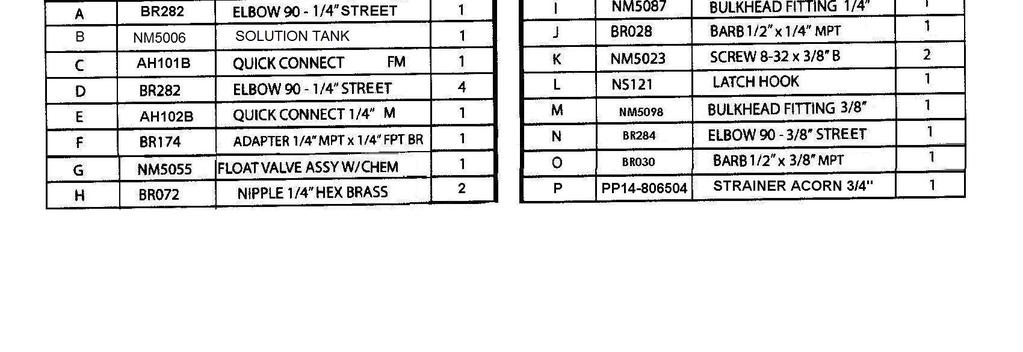
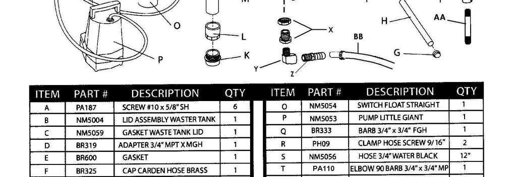
37 OLYMPUS AUTO-FILL FLOAT VALVE ASSEMBLY Part Number Description Discharge Tubing Pipe Nipple Chain with Connector Backflow Preventer Float Hanger Clip PDE Float Assembly PHY Magnet Housing Magnet Holder Spring Float Hanger Wire PDE Valve Body Flange Spring Enclosing Tube Diaphragm Elbow 90º Street 1/ Adapter Ceramic Weight Proportioner PDE Magnet Spacer Plunger Screw 8-18 x 1/2 (4 req.) Valve Repair Kit - PDE63-87 (Includes: , , & 63-38) Rubber Washer P Foot Valve Filter PDE100-11P x 1/4 Plastic Tubing XAF Metering Tip - Turquoise 37
38 17 1A 3A 16 DESCRIPTION 1 REGULATOR BODY 1A REGULATOR KNOB W/ YELLOW CAP 2 SPRING 3 SPRING TOP WASHER - STEEL 3A SPRING BOTTOM WASHER - BRASS 4 CAP / RETAINER O-RING (QTY 3) 5 POPPET O-RING 6 POPPET 7 POPPET SPRING 8 RETAINING RING 9 SPRING BALL SEAT 10 BALL 11 STEM NUT 12 OUTLET ADAPTER CAP 13 INLET ADAPTER CAP 14 STEM RETAINER 15 SEAT 16 STEM 17 NUT SET POINT LOCK (QTY 2) 18 STEM O-RING 19 STEM SPACER (QTY 2) 20 SMALL STEM O-RING 21 SMALL STEM SPACER (QTY 2) 22 ROLL PIN NS PT016A - REGULATOR REPAIR KIT (Includes: 4, 5, 6, 7, 8, 9, 10, 15, 18, 19, 20 & 21) #20 & #21 Items not shown: Located on Stem Inside Retainer
39 39
40 40

41 41

42 42


43 43

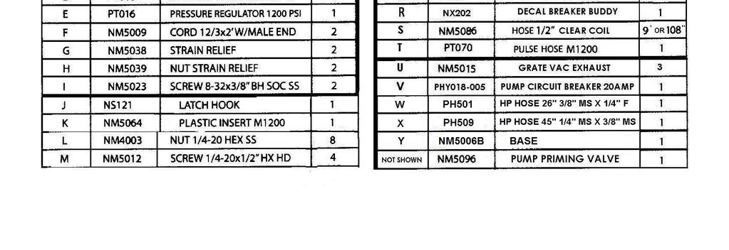
44 44
TOPIC PAGE # SECTION 1: Operational Safety Electrical Safety 6 Mechanical Safety 7
 1 REVISED: 1-31-06 Olympus M200H Operating Manual TABLE OF CONTENTS TOPIC PAGE # Introduction 3 Technical Specifications 4 Optional Equipment 5 SECTION 1: Operational Safety Electrical Safety 6 Mechanical
TOPIC PAGE # Introduction 3 Technical Specifications 4 Optional Equipment 5. SECTION 1: Operational Safety Electrical Safety 6 Mechanical Safety 7
 1 REVISED: 1-31-06 Olympus M100 Operating Manual TABLE OF CONTENTS TOPIC PAGE # Introduction 3 Technical Specifications 4 Optional Equipment 5 SECTION 1: Operational Safety Electrical Safety 6 Mechanical
TOPIC PAGE # Introduction 3 Technical Specifications 4 Optional Equipment 5. SECTION 1: Operational Safety Electrical Safety 6 Mechanical Safety 7
 1 REVISED: 1-31-06 Olympus M3-500 Operating Manual TABLE OF CONTENTS TOPIC PAGE # Introduction 3 Technical Specifications 4 Optional Equipment 5 SECTION 1: Operational Safety Electrical Safety 6 Mechanical
TOPIC PAGE # Introduction 3 Technical Specifications 4 Optional Equipment 5
 1 Olympus M200 Operating Manual TABLE OF CONTENTS TOPIC PAGE # Introduction 3 Technical Specifications 4 Optional Equipment 5 SECTION 1: Operational Safety Electrical Safety 6 Mechanical Safety 7 SECTION
TOPIC PAGE # Introduction 3 Technical Specifications 4 Optional Equipment 5
 1 Olympus M200H Operating Manual TABLE OF CONTENTS TOPIC PAGE # Introduction 3 Technical Specifications 4 Optional Equipment 5 SECTION 1: Operational Safety Electrical Safety 6 Mechanical Safety 7 SECTION
1200 psi Hard Surface Extractor
 1200 PSI Hard Surface Extractor By Sandia Products Please fill out the following information: Model No: Serial No: Distributor Name: Distributor Phone No: Date of Purchase: Safety, Operation and Maintenance
EXTRACTOR Operation & Maintenance Manual
 EXTRACTOR Operation & Maintenance Manual 12 Gallon Carpet Extractor Models 2-100 2-100-H 3-100 3-100-H 2-200 2-200-H 3-200 3-200-H 2-500 2-500-H 3-500 3-500-H US & Foreign Patents Pending The design features
Explorer CleaningPartsDirect.com Carpet Extractor. Operator and Parts Manual. Home Find... Go To.. Model No.: Can.
 Explorer 1500 Carpet Extractor Model No.: 608808 609231 Can. Operator and Parts Manual CleaningPartsDirect.com 662-393-3045 NOBLES 12875 RANSOM STREET HOLLAND MI 49424 U.S.A. CUSTOMER SERVICE: 1-800-365-6625
SAFETY OPERATION & MAINTENANCE MANUAL X-405 CARPET EXTRACTOR This unit is intended for commercial use.
 SAFETY OPERATION & MAINTENANCE MANUAL X-405 CARPET EXTRACTOR This unit is intended for commercial use. READ AND FOLLOW ALL INSTRUCTIONS, WARNINGS AND CAUTIONS BEFORE USING THIS EXTRACTOR Address: 777 South
Operating and Maintenance Manual
 Models: FX-88 FX-88HP Operating and Maintenance Manual Congratulations and thank you for buying a FX-88 portable extractor. The FX-88 is designed to give you truckmount performance in a portable machine
SOLUS-500 EXTRACTOR 120V
 SOLUS-500 EXTRACTOR 120V INFORMATION & OPERATING INSTRUCTIONS DO NOT OPERATE MACHINE UNTIL YOU HAVE READ ALL SECTIONS OF THIS INSTRUCTIONS IMPROPER USE OF THE MACHINE WILL VOID THE WARRANTY 1. Always use
User Manual AIR HOG. Vacuum Booster REV. 3/20/ Stowe Dr. Poway, CA P: (858) F: (858)
 F: (858)") User Manual AIR HOG Model: 7303L Vacuum Booster REV. 3/20/18 13655 Stowe Dr. Poway, CA 92064 P: (858) 679-1191 F: (858) 726-6005 INTRODUCTION Dear Customer: Congratulations on the purchase of your new
User Manual AIR HOG Model: 7303L Vacuum Booster REV. 3/20/18 13655 Stowe Dr. Poway, CA 92064 P: (858) 679-1191 F: (858) 726-6005 INTRODUCTION Dear Customer: Congratulations on the purchase of your new
OPERATOR'S MANUAL. IMPORTANT: READ OPERATOR'S MANUAL CAREFULLY Please fill out & return your warranty card! DP80405
 CARBON SPOT 30 EXTRACTOR OPERATOR'S MANUAL IMPORTANT: READ OPERATOR'S MANUAL CAREFULLY Please fill out & return your warranty card! DP80405 Diamond Products www.diamondproductsus.com Printed in the U.S.A.
BEFORE OPERATING THE MACHINE: WARNING
 BEFORE OPERATING THE MACHINE: Read the manual carefully and completely before attempting to operate the unit. This manual has important information for the use and safe operation of the machine. Keep this
SAFETY OPERATION & MAINTENANCE MANUAL X-612 CARPET EXTRACTOR
 SAFETY OPERATION & MAINTENANCE MANUAL X-612 CARPET EXTRACTOR W/PARTS LIST This unit is intended for commercial use. READ AND FOLLOW ALL INSTRUCTIONS, WARNINGS AND CAUTIONS BEFORE USING THIS EXTRACTOR Address:
HHP-300 EXTRACTOR 120V
 CARPET HHP-300 EXTRACTOR 120V 1 2 CORD 1 3 VAC PUMP UPHOLSTERY MODE INFORMATION & OPERATING INSTRUCTIONS DO NOT OPERATE MACHINE UNTIL YOU HAVE READ ALL SECTIONS OF THIS INSTRUCTIONS IMPROPER USE OF THE
SOLUS-310 EXTRACTOR 120V
 SOLUS-310 EXTRACTOR 120V INFORMATION & OPERATING INSTRUCTIONS DO NOT OPERATE MACHINE UNTIL YOU HAVE READ ALL SECTIONS OF THIS INSTRUCTIONS IMPROPER USE OF THE MACHINE WILL VOID THE WARRANTY 1. Always use
ADVANTAGE-100H-SC EXTRACTOR
 ADVANTAGE-100H-SC EXTRACTOR 120V INFORMATION & OPERATING INSTRUCTIONS CAUTION: DO NOT OPERATE MACHINE UNTIL YOU HAVE READ ALL SECTIONS OF THIS INSTRUCTION MANUAL IMPROPER USE OF THE MACHINE WILL VOID THE
MIRAI EXTRACTOR 100V DO NOT OPERATE MACHINE UNTIL YOU HAVE READ ALL SECTIONS OF THESE INSTRUCTIONS IMPROPER USE OF THE MACHINE WILL VOID THE WARRANTY
 MIRAI EXTRACTOR 100V LOCATOR 1 2 3 4 MODE VAC 1 VAC 2 PUMP BYPASS INFORMATION & OPERATING INSTRUCTIONS DO NOT OPERATE MACHINE UNTIL YOU HAVE READ ALL SECTIONS OF THESE INSTRUCTIONS IMPROPER USE OF THE
120V CAUTION: DO NOT OPERATE MACHINE UNTIL YOU HAVE READ ALL SECTIONS OF THIS INSTRUCTION MANUAL IMPROPER USE OF THE MACHINE WILL VOID THE WARRANTY
 KING COBRA 1200 120V INFORMATION & OPERATING INSTRUCTIONS CAUTION: DO NOT OPERATE MACHINE UNTIL YOU HAVE READ ALL SECTIONS OF THIS INSTRUCTION MANUAL IMPROPER USE OF THE MACHINE WILL VOID THE WARRANTY
CAUTION: DO NOT OPERATE MACHINE UNTIL YOU HAVE READ ALL SECTIONS OF THIS INSTRUCTION MANUAL
 KING COBRA 310 120V INFORMATION & OPERATING INSTRUCTIONS U. S. PRODUCTS CAUTION: DO NOT OPERATE MACHINE UNTIL YOU HAVE READ ALL SECTIONS OF THIS INSTRUCTION MANUAL 56041963 IMPROPER USE OF THE MACHINE
SOLUS-310R EXTRACTOR
 SOLUS-310R EXTRACTOR 120V INFORMATION & OPERATING INSTRUCTIONS DO NOT OPERATE MACHINE UNTIL YOU HAVE READ ALL SECTIONS OF THIS INSTRUCTIONS IMPROPER USE OF THE MACHINE WILL VOID THE WARRANTY 1. Always
COBRA -300H EXTRACTOR
 COBRA -300H EXTRACTOR 120V INFORMATION & OPERATING INSTRUCTIONS DO NOT OPERATE MACHINE UNTIL YOU HAVE READ ALL SECTIONS OF THIS INSTRUCTIONS IMPROPER USE OF THE MACHINE WILL VOID THE WARRANTY 1. Always
SAFETY PRECAUTIONS. 2) Before operating machine: - Make sure all safety devices are in place and operate properly.
 Before operating machine: - Make sure all safety devices are in place and operate properly.") TABLE OF CONTENTS Machine Components Safety Precautions Machine Set Up Machine Operation Machine Maintenance & Storage Troubleshooting Technical Specifications Parts Lists Wiring Diagram 1 2 3 3-4 5 6
TABLE OF CONTENTS Machine Components Safety Precautions Machine Set Up Machine Operation Machine Maintenance & Storage Troubleshooting Technical Specifications Parts Lists Wiring Diagram 1 2 3 3-4 5 6
As part of the V.I.P. family, you are entitled to the best protection by one of the most comprehensive warranties in the industry.
 CONGRATULATIONS on your purchase of a Viper product, and welcome to the V.I.P. family. We appreciate your business and will do everything in our power to keep you happy with your purchase for many years
COBRA -H EXTRACTOR 120V
 COBRA -H EXTRACTOR 120V INFORMATION & OPERATING INSTRUCTIONS CAUTION: DO NOT OPERATE MACHINE UNTIL YOU HAVE READ ALL SECTIONS OF THIS INSTRUCTION MANUAL IMPROPER USE OF THE MACHINE WILL VOID THE WARRANTY
SAFETY, OPERATION AND MAINTENANCE MANUAL. MX-1408 SELF-CONTAINED EXTRACTOR This unit is intended for commercial use.
 SAFETY, OPERATION AND MAINTENANCE MANUAL MX-1408 SELF-CONTAINED EXTRACTOR This unit is intended for commercial use. READ & FOLLOW ALL INSTRUCTIONS, WARNINGS & CAUTIONS BEFORE USING THIS EXTRACTOR This
XLT-60 EXTRACTOR 120V CAUTION: DO NOT OPERATE MACHINE UNTIL YOU HAVE READ ALL SECTIONS OF THIS INSTRUCTION MANUAL
 XLT-60 EXTRACTOR 120V INFORMATION & OPERATING INSTRUCTIONS CAUTION: DO NOT OPERATE MACHINE UNTIL YOU HAVE READ ALL SECTIONS OF THIS INSTRUCTION MANUAL 56041883 IMPROPER USE OF THE MACHINE WILL VOID THE
Prospector PE300 Extractor With Heat
 PE300 Extractor with Heat By Jon-Don, Inc. Please fill out the following information: Model No: Serial No: Distributor Name: Distributor Phone No: Date of Purchase: Safety, Operation and Maintenance Manual
SOLUS-310 EXTRACTOR 120V
 SOLUS-310 EXTRACTOR 120V INFORMATION & OPERATING INSTRUCTIONS DO NOT OPERATE MACHINE UNTIL YOU HAVE READ ALL SECTIONS OF THIS INSTRUCTIONS IMPROPER USE OF THE MACHINE WILL VOID THE WARRANTY 1. Always use
HP310-C EXTRACTOR 120V
 HP310-C EXTRACTOR 120V 1 2 3 VAC 1 VAC 2 PUMP INFORMATION & OPERATING INSTRUCTIONS DO NOT OPERATE MACHINE UNTIL YOU HAVE READ ALL SECTIONS OF THIS INSTRUCTIONS IMPROPER USE OF THE MACHINE WILL VOID THE
Trooper Portable Carpet Extractor. Operator and Parts Manual. Model No.: Can Rev. 00 (09-99)
") Trooper 1000 Portable Carpet Extractor Model No.: 608811 609229 Can. Operator and Parts Manual NOBLES 12875 RANSOM STREET HOLLAND MI 92 U.S.A. CUSTOMER SERVICE: 1-800-365-6625 FAX: 1 800 678 20 608812
Trooper 1000 Portable Carpet Extractor Model No.: 608811 609229 Can. Operator and Parts Manual NOBLES 12875 RANSOM STREET HOLLAND MI 92 U.S.A. CUSTOMER SERVICE: 1-800-365-6625 FAX: 1 800 678 20 608812
DO NOT OPERATE THE MACHINE UNTIL YOU HAVE READ ALL SECTIONS OF THE INSTRUCTIONS IMPROPER USE OF THE MACHINE WILL VOID THE WARRANTY
 KING COBRA 500 120V INFORMATION & OPERATING INSTRUCTIONS DO NOT OPERATE THE MACHINE UNTIL YOU HAVE READ ALL SECTIONS OF THE INSTRUCTIONS IMPROPER USE OF THE MACHINE WILL VOID THE WARRANTY 1. Always use
TERMINATOR 120V CAUTION: DO NOT OPERATE MACHINE UNTIL YOU HAVE READ ALL SECTIONS OF THIS INSTRUCTION MANUAL
 TERMINATOR 120V INFORMATION & OPERATING INSTRUCTIONS CAUTION: DO NOT OPERATE MACHINE UNTIL YOU HAVE READ ALL SECTIONS OF THIS INSTRUCTION MANUAL 56041962 IMPROPER USE OF THE MACHINE WILL VOID THE WARRANTY
Prospector PE500 Extractor WIth Heat
 Please read before use! 500 PSI, Dual 3-Stage Motors REGISTER YOUR MACHINE ONLINE! Prospector PE500 Extractor WIth Heat Safety, Operation and Maintenance Manual with Parts List Model No. PE500 Reliable
Tornado Operation & Maintenance Manual
 TORNADO INDUSTRIES 7401 W. LAWRENCE AVENUE CHICAGO, IL 60706 (708) 867-5100 FAX (708) 867-6968 www.tornadovac.com Tornado Operation & Maintenance Manual For Commercial Use Only 12 Gallon CarpetRinser/Dryer
8070 Mytee Lite. Instructions for. Please read before use. Register your product at support/register.
 Instructions for 8070 Mytee Lite Please read before use. Register your product at http://www.mytee.com/ support/register Model # Serial # Form # ADP-8070 06-16 1 GENERAL INFORMATION Dear Customer: Congratulations
Upholstery and Drapery Cleaner. Operator and Parts Manual. Model No.: gal Extractor. MNL32506 Rev. 00 (08-98)
") 32506 Upholstery and Drapery Cleaner Model No.: 32506 3 gal Extractor Operator and Parts Manual KLEENRITE 1122 MAPLE STREET MADERA CA 93637 U.S.A. FAX: 1-559-673-5725 CUSTOMER SERVICE: 1-800-241-4865 MNL32506
32506 Upholstery and Drapery Cleaner Model No.: 32506 3 gal Extractor Operator and Parts Manual KLEENRITE 1122 MAPLE STREET MADERA CA 93637 U.S.A. FAX: 1-559-673-5725 CUSTOMER SERVICE: 1-800-241-4865 MNL32506
AGITATOR V DO NOT OPERATE THE MACHINE UNTIL YOU HAVE READ ALL SECTIONS OF THESE INSTRUCTIONS IMPROPER USE OF THE MACHINE WILL VOID THE WARRANTY
 AGITATOR 20 120V INFORMATION & OPERATING INSTRUCTIONS DO NOT OPERATE THE MACHINE UNTIL YOU HAVE READ ALL SECTIONS OF THESE INSTRUCTIONS IMPROPER USE OF THE MACHINE WILL VOID THE WARRANTY 1. Always use
INFORMATION & OPERATING INSTRUCTIONS
 KING COBRA 310 120V INFORMATION & OPERATING INSTRUCTIONS DO NOT OPERATE MACHINE UNTIL YOU HAVE READ ALL SECTIONS OF THE INSTRUCTIONS IMPROPER USE OF THE MACHINE WILL VOID THE WARRANTY 1. Always use a defoamer
ADVANTAGE-400H EXTRACTOR
 ADVANTAGE-400H EXTRACTR 120V INFRMATIN & PERATING INSTRUCTINS CAUTIN: D NT PERATE MACHINE UNTIL YU HAVE READ ALL SECTINS F THIS INSTRUCTIN MANUAL 56041940 IMPRPER USE F THE MACHINE WILL VID THE WARRANTY
SURFACE CLEANING TOOL AR51S SX-15
 Revised: 06/16/15 LMANAR51S SX-15 Gekko Tool HARD SURFACE CLEANING TOOL AR51S SX-15 Head Assembly with Gekko Handle AR51A Hydro-Force Manufacturing 4282 South 590 West Salt Lake City, UT 84123 801-268-2673
MAXUM 5 5 Gallon Box Extractor
 MAXUM 5 5 Gallon Box Extractor INTRODUCTION OPERATING & MAINTENANCE INSTRUCTIONS This operator s book has important information for the use and safe operation of this machine. Read this book carefully
ADVANTAGE 1200 EXTRACTOR
 ADVANTAGE 100 EXTRACTR 10V INFRMATIN & PERATING INSTRUCTINS CAUTIN: D NT PERATE MACHINE UNTIL YU HAVE READ ALL SECTINS F THIS INSTRUCTIN MANUAL IMPRPER USE F THE MACHINE WILL VID THE WARRANTY 56041934
Self Contained Carpet Extractor. Operator and Parts Manual. Model No.: V V/60HZ V/50HZ Rev.
 90 Self Contained Carpet Extractor Model No.: 0939 20V 09383 230V/0HZ 0932 240V/50HZ Operator and Parts Manual TENNANT COMPANY Commercial Products 2875 RANSOM STREET HOLLAND MI 49424 FAX: 800 78 4240 CUSTOMER
INTRODUCTION Congratulations on your purchase of the SX-15 hard surface cleaning tool. Years of experience, engineering, and planning have gone into t
 Revised: 02/11/13 LMANAW105 SX-15 HARD SURFACE CLEANING TOOL AW105 Hydro-Force Manufacturing 4282 South 590 West Salt Lake City, UT 84123 801-268-2673 801-268-3856 FAX 1 INTRODUCTION Congratulations on
Nilfisk Inc Winnetka Avenue North Minneapolis, MN REV.03( ) VF80189
 VF80189") Nilfisk Inc. 9435 Winnetka Avenue North Minneapolis, MN 55445 www.usviper.com REV.03(05-) VF8089 SAFETY PRECAUTIONS This machine is intended for commercial use. It is constructed for use in an indoor
Nilfisk Inc. 9435 Winnetka Avenue North Minneapolis, MN 55445 www.usviper.com REV.03(05-) VF8089 SAFETY PRECAUTIONS This machine is intended for commercial use. It is constructed for use in an indoor
PUREPOWER SERIES CENTRAL VACUUM POWER UNITS PP500, PP600 & PP650
 USER GUIDE PUREPOWER SERIES CENTRAL VACUUM POWER UNITS PP500, PP600 & PP650 AB0039 FOR RESIDENTIAL USE ONLY!! MODELS SFDB-DQ, SFDB-DR AND SFDB-DS 30042509E IMPORTANT SAFETY INSTRUCTIONS SAVE THESE INSTRUCTIONS
6-Gallon Carpet Extractor Series
 Limited Warranty CleanFreak warrants new equipment against defects in material and workmanship under normal use and service to the original purchaser. Any statutory implied warranties, including any warranty
Flood Pumper Plus. Water Transfer Machine. Operator and Parts Manual. Model No.: Rev. 00 (11-99)
") Flood Pumper Plus Water Transfer Machine Model No.: 607841 Operator and Parts Manual NOBLES 12875 RANSOM STREET HOLLAND MI 49424 U.S.A. CUSTOMER SERVICE: 1-800-365-6625 FAX: 1 800 678 4240 608468 Rev.
Flood Pumper Plus Water Transfer Machine Model No.: 607841 Operator and Parts Manual NOBLES 12875 RANSOM STREET HOLLAND MI 49424 U.S.A. CUSTOMER SERVICE: 1-800-365-6625 FAX: 1 800 678 4240 608468 Rev.
WATER CLAW SUB-SURFACE FLOOD EXTRACTION TOOL AC016 - AC018. Water Claw 4282 South 590 West Salt Lake City, UT FAX
 Revised: 02/19/15 LB110 WATER CLAW SUB-SURFACE FLOOD EXTRACTION TOOL AC016 - AC018 Water Claw 4282 South 590 West Salt Lake City, UT 84123 801-268-2673 801-268-3856 FAX 1 INTRODUCTION Congratulations on
FLASH XTRACTOR II NEXT GENERATION SUB-SURFACE FLOOD EXTRACTION TOOL AC002
 Revised: 10/23/14 LMANAC002 FLASH XTRACTOR II NEXT GENERATION SUB-SURFACE FLOOD EXTRACTION TOOL AC002 Water Claw 4282 South 590 West Salt Lake City, UT 84123 801-268-2673 801-268-3856 FAX 1 INTRODUCTION
17 GALLON PROFESSIONAL RESTROOM CLEANER
 CR2 COMPLETE RESTROOM RESTORATION 17 GALLON PROFESSIONAL RESTROOM CLEANER OWNER S/OPERATOR S MANUAL PROUDLY DESIGNED AND MANUFACTURED BY WWW.EDIC-USA.COM UNPACKING YOUR NEW CR2: When your machine is delivered,
Operation and Maintenance Manual BLIZZARD50 CS6-50-VD 120V/60HZ
 Operation and Maintenance Manual BLIZZARD50 CS6-50-VD 120V/60HZ CS6-50-VD Operation & Maintenance Manual Table of Contents: 1.0 Introduction 1 2.0 Unpacking your COOL- SPACE 1 3.0 Set-up of COOL-SPACE
Owner s Manual HVE3000 Flood Pumper and Inline Booster
 Owner s Manual HVE3000 Flood Pumper and Inline Booster DRI-EAZ PRODUCTS, INC. SAPPHIRE SCIENTIFIC, INC. F479 78-006 15180 Josh Wilson Road 2604 Liberator Burlington, WA 98233 Prescott, AZ 86301 www.dri-eaz.com
MAXUM Gallon Box Extractor
 MAXUM 12 12 Gallon Box Extractor INTRODUCTION OPERATING & MAINTENANCE INSTRUCTIONS This operator s book has important information for the use and safe operation of this machine. Read this book carefully
READ AND UNDERSTAND THESE INSTRUCTIONS BEFORE OPERATING THE MACHINE
 XAACT Xtract 200 INFORMATION & OPERATING INSTRUCTIONS READ AND UNDERSTAND THESE INSTRUCTIONS BEFORE OPERATING THE MACHINE 78-00018 Rev B 032912 1 CONTENTS: Machine Specifications............ 2 Record Important
CONGRATULATIONS! TABLE OF CONTENTS
 CONGRATULATIONS! Thank you for choosing Mytee Products for your supply needs. By doing so, you have joined thousands of your fellow cleaning professionals in choosing quality, service, and value in your
MANUAL OWNER S. Operating and Servicing Instructions IMPORTANT: READ CAREFULLY BEFORE ASSEMBLY AND USE.
 OWNER S MANUAL Operating and Servicing Instructions www.hoover.com.hk HW-FM-HKA IMPORTANT: READ CAREFULLY BEFORE ASSEMBLY AND USE. THIS PRODUCT IS INTENDED FOR HOUSEHOLD USE ONLY. IF USED COMMERCIALLY
TFC 400. OPERATOR MANUAL Clarke MODEL /09 Rev C Document Number
 TFC 400 OPERATOR MANUAL Clarke MODEL 56380773 1 11/09 Rev C Document Number 56380889 IMPORTANT SAFETY INSTRUCTIONS This machine is only suitable for commercial use, for example, in hotels, schools, hospitals,
Minor Home Repairs. November 4, County of Henrico Department of Community Revitalization
 Minor Home Repairs 1 November 4, 2017 County of Henrico Department of Community Revitalization Educate homeowners on basic technical skills that will help the homeowner understand daily operations of different
PE500 Carpet Extractor
 Jon-Don, Inc. warrants new equipment against defects in material and workmanship under normal use and service to the original purchaser. Any statutory implied warranties, including any warranty of merchantability
Operation and Maintenance Manual 120V/60HZ
 Operation and Maintenance Manual 120V/60HZ GLACIER CS5-16-VD CS5-16-VD-TB CS5-18-VD CS5-18-VD-TB AVALANCHE CS6-36-1D CS6-36-VD BLIZZARD CS6-50-VD Operation & Maintenance Manual 60HZ Models Table of Contents:
Operation and Maintenance Manual GLACIER TALL BASE CS5-16-VD-TB CS5-18-VD-TB2 120V/60HZ
 Operation and Maintenance Manual GLACIER TALL BASE CS5-16-VD-TB CS5-18-VD-TB2 120V/60HZ Operation & Maintenance Manual Table of Contents: 1.0 Introduction 1 2.0 Unpacking your COOL- SPACE 1 3.0 Set-up
Parts and Instruction Manual EX12 Carpet Extractor
 Parts and Instruction Manual EX12 Carpet Extractor This manual is furnished with each new MINUTEMAN EX 12. This provides the necessary operating and preventive maintenance instructions. Operators must
READ AND UNDERSTAND THESE INSTRUCTIONS BEFORE OPERATING THE MACHINE
 XAACT Xtract 500 INFORMATION & OPERATING INSTRUCTIONS READ AND UNDERSTAND THESE INSTRUCTIONS BEFORE OPERATING THE MACHINE 78-00015 Rev B 032912 1 CONTENTS: Machine Specifications............ 2 Record Important
Operator & Parts Manual Self_Contained Extractor ie U REV.05( ) INTERNATIONAL CLEANING EQUIPMENT
 INTERNATIONAL CLEANING EQUIPMENT") www.icecompanies.com Operator & Parts Manual Self_Contained Extractor ie410 6210149U REV.05(11-2016) INTERNATIONAL CLEANING EQUIPMENT TABLE OF CONTENTS SAFETY PRECAUTION..................... 2 MACHINE
www.icecompanies.com Operator & Parts Manual Self_Contained Extractor ie410 6210149U REV.05(11-2016) INTERNATIONAL CLEANING EQUIPMENT TABLE OF CONTENTS SAFETY PRECAUTION..................... 2 MACHINE
CFX-27 GALLON PORTABLE EXTRACTOR. Owner s Manual CFX 1/22/2010
 ` CFX-27 GALLON PORTABLE EXTRACTOR Owner s Manual CFX 1/22/2010 1 Overview The Rotovac CFX-27 has an extra large 27 gallon clean water holding tank and an automatic waste water pump out system. In addition,
π H-2268 SANITAIRE UPRIGHT VACUUM SAFETY uline.com
 π H-2268 SANITAIRE UPRIGHT VACUUM 1-800-295-5510 uline.com SAFETY PAGE 1 OF 7 NOTE: When using an electrical appliance, basic precautions should always be followed, including the following: READ ALL INSTRUCTIONS
Model: C C Ambassador 20. Automatic Carpet Scrubber OPERATION SERVICE PARTS CARE
 Ambassador 20 Automatic Carpet Scrubber Model: C8420-115 C8420-240 OPERATION SERVICE PARTS CARE This manual is furnished with each new Minuteman Ambassador 20. This provides the necessary operating and
FLOOD KING 120V. 2. Keep all filters clean. Do not operate the machine if the filters are clogged.
 FLOOD KING 120V INFORMATION & OPERATING INSTRUCTIONS DO NOT OPERATE THE MACHINE UNTIL YOU HAVE READ ALL SECTIONS OF THESE INSTRUCTIONS. IMPROPER USE OF THE MACHINE WILL VOID THE WARRANTY 1. Always be sure
Fully Automatic Water Softeners
 OWNERS GUIDE TO INSTALLATION AND OPERATION Fully Automatic Water Softeners SINGLE TANK CABINET MODELS TWO TANK MODELS Read the instructions carefully and learn the specific details regarding installation
C-Box 100, H-Box 200 & H-Box 500
 C-Box 100, H-Box 200 & H-Box 500 Table of Contents Technical specifications... 3 Safety precautions... 4 Grounding instructions... 4 Machine components... 5-6 lectrical requirements... 6 Machine set-up...
ESTEAM CLEANING SYSTEMS OWNER S MANUAL
 ESTEAM CLEANING SYSTEMS OWNER S MANUAL Congratulations on your selection of a new E1700 Series soil extractor built in Canada by Esteam Cleaning Systems. Our goal has been to produce the best high performance
Sanitaire. Owner s Guide. 10 GALLON Box Extractor SC6088 Series IMPORTANT
 Sanitaire 10 GALLON Box Extractor SC6088 Series Part No. SC6088 Rev 2 (3/14) Owner s Guide IMPORTANT Do not return this product to the store. Call 1-800-800-8975* Monday - Friday 8:00 AM to 7:30 PM and
Model Series ELECTRIC WATER SYSTEM PUMP. PumpAgents.com - buy pumps and parts online. Model Series. Automatic Multi-Outlet FEATURES
 PumpAgents.com - Click here for Pricing/Ordering Model 36950-2 Series ELECTRIC WATER SYSTEM PUMP Automatic Multi-Outlet FEATURES Self-Priming Diaphragm Design Allows Dry Running Built-in Discharge Check
HID312, HID525 and HID540 Meridian Ice Maker-Dispensers Technical Service
 HID312, HID525 and HID540 Meridian Ice Maker-Dispensers Technical Service What you will learn Introduction Installation Operation Maintenance Take It Apart Diagnostics HID Ice Maker-Dispensers HID models
Welcome! Today s topic: Small Home Repairs. November 14, 2015
 Welcome! Today s topic: Small Home Repairs November 14, 2015 Small Home Repairs Course Presented by Monique Johnson Environmental Green Solutions, LLC Objective Educate homeowners on basic technical skills
Operation and Maintenance Manual 120V/60HZ
 Operation and Maintenance Manual 120V/60HZ GLACIER CS5-18-VD CS5-18-VD-TB AVALANCHE CS6-36-1D CS6-36-VD BLIZZARD CS6-50-VD Contents 1.0 INTRODUCTION... 1 2.0 UNPACKING YOUR COOL-SPACE UNIT... 1 3.0 SET-UP
GARAGE VAC OWNERS MANUAL READ BEFORE OPERATING YOUR SYSTEM
 GARAGE VAC OWNERS MANUAL READ BEFORE OPERATING YOUR SYSTEM IMPORTANT SAFETY INSTRUCTIONS When using an electrical appliance, basic precautions should always be followed, including the following: * Read
If additional information is needed, please contact EDIC at: or
 WARNING CARPET CLEANER Any piece of equipment can be dangerous if not operated properly. YOU are responsible for the safe operation of this equipment. The operator must carefully read and follow any warnings,
CBT LW MAINTENANCE GUIDE
 CBT LW MAINTENANCE GUIDE PICTOGRAMS Each Signifier displayed here is specific to this User Manual. Menu Previous Advance Note Tip Example Powder Feeder Mixing Bowl Weigh Scale CBP Tanks Control Panel PSD
Parts and Instruction Manual TRS 14 Total Recovery System
 Parts and Instruction Manual TRS 14 Total Recovery System This manual is furnished with each new MINUTEMAN TRS 14. This provides the necessary operating and preventive maintenance instructions. Operators
IMAGE V. Parts and Service Manual
 IMAGE 0V Section II Parts and Service Manual (88B) CLARKE TECHNOLOGY Image Operator's Manual Page AUTHORIZED PERSONNEL MAINTENANCE To Access Pump Motor. Remove brush housing from machine. See "Brush Motor
Setup. Important. Texture Spraying (material supplied from unit)
") Setup Setup Important If you are going to stop spraying for more than 5 minutes, turn sprayer off to prevent shortened pump hose life. Do not allow material to dry inside pump, hoses, gun or spray system.
Setup Setup Important If you are going to stop spraying for more than 5 minutes, turn sprayer off to prevent shortened pump hose life. Do not allow material to dry inside pump, hoses, gun or spray system.
Tornado Operations & Maintenance Manual
 TORNADO INDUSTRIES 7401 W. LAWRENCE AVENUE CHICAGO, IL 60706 (708) 867-5100 FAX (708) 867-6968 www.tornadovac.com Tornado Operations & Maintenance Manual MODEL NO. 99690 BD 22/14, 99720 BD 26/14 L9722
Mopit 4 Operator s / Service Manual
 Mopit 4 Operator s / Service Manual FOR PARTS AND SERVICE 1-800-290-2833 To view Mopit 4 instructional videos scan this qr code with your smart phone. You can also find Mopit 4 instructional videos on
OPERATIONS MANUAL & PARTS LIST. BX2 Fastracts Extractor. IPC Eagle 3650 Dodd Rd, Eagan MN
 OPERATIONS MANUAL & PARTS LIST BX2 Fastracts Extractor IPC Eagle 3650 Dodd Rd, Eagan MN 55123 800.486.2775 www.ipceagle.com BEFORE OPERATING THE MACHINE Read the manual carefully and completely before
Xaact Spot. Xaact Hot Spot
 Xaact Spot & Xaact Hot Spot INFORMATION & OPERATING INSTRUCTIONS READ AND UNDERSTAND THESE INSTRUCTIONS BEFORE OPERATING THE MACHINE 78-00012 Rev. 101211 1 CONTENTS: Machine Specifications............
HOTSPOT. Two Gallon Pump Up Spotter OPERATING & MAINTENANCE
 HOTSPOT Two Gallon Pump Up Spotter INTRODUCTION OPERATING & MAINTENANCE INSTRUCTIONS This operator s book has important information for the use and safe operation of this machine. Read this book carefully
K 2.97 M. Specifications Operating pressure, max PSI Water volume GPM Voltage V Amp draw AMPS
 K 2.97 M High Pressure Washer Operator Manual Overview... 2 Important Precautions... 3-4 Assembly Instructions... 4 Operating Instructions... 5 GFCI Instructions... 6 Using the Accessories... 6 Working
WATER CLAW SUB-SURFACE FLOOD EXTRACTION TOOL AC015 - AC016 - AC018
 Revised: 04/27/11 LB110 WATER CLAW SUB-SURFACE FLOOD EXTRACTION TOOL AC015 - AC016 - AC018 Water Claw 4282 South 590 West Salt Lake City, UT 84123 801-268-2673 801-268-3856 FAX 1 INTRODUCTION Congratulations
GALAXY FLOOR MACHINE
 OPERATION MANUAL GALAXY FLOOR MACHINE IMPORTANT SAFETY INSTRUCTIONS WARNING: Failure to observe these instructions can cause personal injury to machine operator or bystanders. WARNING: Shock or electrocution
User Manual. Floor Scrubber Disc Brush Drive
 User Manual Floor Scrubber Disc Brush Drive This manual is furnished with each new Floor Scrubber. This provides the necessary operating and preventive maintenance instructions. Operators must read and
MICRO CLEANER. OPERATOR MANUAL Advance MODEL /10 Rev E Document Number
 MICRO CLEANER OPERATOR MANUAL Advance MODEL 56380771 2/10 Rev E Document Number 563808911 IMPORTANT SAFETY INSTRUCTIONS This machine is only suitable for commercial use, for example, in hotels, schools,
GALAXY 5 Owner s Manual & Parts List
 GALAXY 5 Owner s Manual & Parts List This equipment is intended for commercial use only GALAXY 5 MODELS 500BX 500BX-EH 500BX-HR 1753 Blake Avenue Los Angeles, CA 90031 1-(800)-338-EDIC, or in CA 1-(323)-660-1635
MC MC MC MC MC833130
 Pic-A-Vac Model: MC832085 MC833085 MC832105 MC833105 MC832130 MC833130 OPERATION SERVICE PARTS CARE Revised 8/01 FOR COMMERCIAL USE ONLY IMPORTANT SAFETY INSTRUCTIONS When using an electrical appliance,
CONTENTS CONSIDERATIONS. General Plumbing Component Connection ILLUSTRATION. Control System CONFIGURATION. Voltage Verification CONNECTION
 AIR SERIES SYSTEM INSTALLATION MANUAL CONTENTS CONSIDERATIONS General Plumbing Component Connection 2 2 2 ILLUSTRATION Control System 3 CONFIGURATION Voltage Verification 4 CONNECTION Component Connection
3 GALLON SELF-CONTAINED EXTRACTOR
 w FIVESTAR 401TR 411TR 3 GALLON SELF-CONTAINED EXTRACTOR OWNER S/OPERATOR S MANUAL PROUDLY DESIGNED AND MANUFACTURED BY WWW.EDIC-USA.COM UNPACKING YOUR NEW FIVESTAR: When your package is delivered, check
Model Series Series
 PumpAgents.com - Click here for Pricing/Ordering Model 36800-Series 36900-Series ELECTRIC WATER SYSTEM PUMPS Automatic Multi-Outlet FEATURES Self-Priming Diaphragm Design Allows Dry Running Built-in Discharge