STEP Snowmelt. Installation Manual. Low Voltage System
|
|
|
- Clyde Chambers
- 5 years ago
- Views:
Transcription


1 STEP Snowmelt Installation Manual Low Voltage System
2 Contents STEP SNOWMELT SYSTEM... 3 BENEFITS... 3 INSTALLATION GUIDELINES... 4 IMPORTANT INSTALLATION GUIDLINES... 4 WARNING... 4 BEFORE STARTING... 5 DESIGN AND CALCULATIONS... 5 SUPPLIED PARTS... 5 DESIGN AND CALCULATION... 6 AC POWER SUPPLY... 6 LOW VOLTAGE DC CONTROLLER... 6 ELEMENT TYPE AND WATTAGE... 7 WIRE GAUGE AND LENGTH... 7 PRODUCT SPECIFICATIONS... 8 CONSTRUCTION... 8 APPLICATION... 8 HEATING ELEMENT MODELS... 9 INSTALLATION PLAN INSTALL CONNECT COVER MAKE THE CONNECTIONS SYSTEM DESIGN ELECTRICAL GUIDELINES LOW VOLTAGE ELECTRIC RADIANT HEATING EQUIPMENT AC POWER SUPPLY WIRING DIAGRAM DC CONTROLLER WIRING DIAGRAM FAIL SAFE WIRING CONTROLS STEP TOUCH THEMOSTAT WARRANTY REGISTRATION AND COVERAGE WARRANTY REGISTRATION CARD TROUBLESHOOTING POWER SUPPLY HEATING ELEMENT P a g e
3 STEP SNOWMELT SYSTEM STEP Snowmelt is a heating solution to melt snow and ice on entrances, walkways, driveways, ramps, patios, etc. The snow melt system eliminates shoveling snow and protects pedestrians from slippery ice or snow covered driveways and sidewalks. STEP Snowmelt systems consist of thin, flat and flexible heating elements that operate on low voltage (AC or DC) and are custom designed for each individual application. These durable, lightweight heating elements can be stapled or nailed through as long as the two embedded bus braids on each side of the element are not penetrated. STEP Snowmelt heating elements are powered by a 24V low voltage AC Power Supply or DC Controller. The heating elements, which can be cut to size on site are available in different widths and protected by a chemically, inherently inert and dielectric insulation. This liner protects against physical damages and aggressive materials and allows heating elements to be installed under concrete or selected other surfaces. STEP Snowmelt heating element is made of a homogeneous, semi-conductive polymer, which by nature is self-regulating. This self-regulating, positive temperature coefficient (PTC), Nanotechnology allows them to heat with maximum power in cold environments and use less electricity as their temperature increases. This minimizes power consumption and reduces operating costs by as much as 60% compared to conventional electric cable systems. BENEFITS STEP Snowmelt is a flat, flexible and thin heating element. The heating element can be cut to length at the jobsite. The polymer material can be penetrated without affecting the conductivity, but the two conductors on each side must not be penetrated. The element is strong and durable. STEP Snowmelt has the ability to self-regulate - as the material gets warmer, less electricity passes through the plastic - therefore it is extremely energy-efficient. The element acts on its whole surface as a sensor and cannot overheat. This heating system is very versatile and can be used for residential, commercial and industrial applications. Avoids shoveling snow, and keeps pedestrians safe. Low operating costs compared to alternative snow melting systems. 3 P a g e
4 INSTALLATION GUIDELINES IMPORTANT INSTALLATION GUIDLINES Choose qualified personnel who are familiar with the STEP Snowmelt heating system. Make sure that all materials used are approved for the specific application and have no adverse compatibility with the heating elements. The polymer material can be penetrated, but do not damage the two bus braids and lead wires on each side of the element. Use only components recommended by the manufacturer. Electrically check and measure the heating system before covering the heating elements. The installation shall be made in accordance with local codes, ordinances, trade practices, and manufacturers' instructions. Read and follow the installation instructions to assure that the calculations and the heating system installed are done according to the specified application. STEP Labels shall be provided with the heating product and should be filled out and affixed in the place indicated: o o CAUTION label is to be attached to the junction box. WARNING label is to be attached to the service panel. WARNING HEATING ELEMENTS SHOULD NOT TOUCH, CROSS OR OVERLAP AT ANY POINT. DO NOT ENERGIZE ROLLED UP HEATING ELLEMENTS. DO NOT NAIL OR STAPLE ANY METALLIC OBJECT THROUGH TERMINALS AND BUS BRAIDS. HEATING ELEMENT IS REQUIRED TO BE INSTALLED BY QUALIFIED PERSONNEL IN ACCORDANCE WITH LOCAL AND NATIONAL CODES SUCH AS NEC IN U.S., CEC IN CANADA. HEATING ELEMENT SHOULD BE TESTED AND MEASURED BEFORE BEING COVERED. READ AND FOLLOW ALL INSTRUCTIONS. These installation instructions assume that the STEP Snowmelt system has been designed by Electro Plastics, Inc. or a distributor of Electro Plastics, Inc. and is being installed according to the proposed Design Specifications, all Terms & Conditions of Sale, and Limited Warranty provided with a STEP Snowmelt quotation. For more information, contact Electro Plastics, Inc. at or the distributor that originally provided the quotation. You can also go to 4 P a g e


.")


5 BEFORE STARTING DESIGN AND CALCULATIONS The installation shall be calculated and a layout made to determine the materials required. The more specific the layout the easier will be the installation. Indicate for each area: o o o o o o Exact measurements of the areas(s) to be heated. Placement and number of strips of elements. Length and wattage per element strip. Location of power source, including electrical box, control and power supply(s). Wire size and length according to load and distance to the power source. Size of AC power supply or DC controller and load distribution on the interface boards. SUPPLIED PARTS STEP Heating Element STEP AC Power Supply STEP DC Controller MEP-30-70W-24V MEP-23-80W-24V EPI-LX-R-500W-24V EPI-LX-R-1000W-24V EPI-LX-R-1500W-24V EPI-DC-M1 EPI-DC-M2 EPI-DC-M3 EPI-DC-M4 EPI-DC-M5 EPI-DC-M6 EPI-DC-M7 EPI-DC-M8 STEP C&T Kit Connectors (tinned copper) Sealant Tape Extension Wire TCu12 or TCu10 Stranded tinned copper STEP T-BLOCK Terminal Board 2-Bar tinned copper STEP TOOL-PRO Recommended crimp tool for connectors Signal Wire (3-Con) From thermostat to AC or DC Controller STEP Touch EPI-LX-TC Thermostat EPI-LX-TS External Sensor 5 P a g e
6 DESIGN AND CALCULATION AC POWER SUPPLY POWER SUPPLY Height (inch) DIMENSIONS Width (inch) Depth (inch) PRIMARY CIRCUIT BREAKER SECONDAY CIRCUIT BREAKER 120 VAC 208 VAC 230 VAC 24 VAC EPI-LX-R A 5A 5A 1 x 25A EPI-LX-R A 10A 10A 2 x 25A EPI-LX-R A 15A 15A 3 x 25A The EPI-LX-R power supply series consist of one to three 500 watts circuits. Designed wattage is 90% or 450 watts. Do not exceed the maximum element length for the selected element type in table Element Type and Wattage Combine element strips from the layout to optimize distribution for each 450 watt circuit in the power supply. All elements must be connected in parallel. LOW VOLTAGE DC CONTROLLER DC CONTROLLER DIMENSIONS CHANNELS Model Height (inch) Width (inch) Length (inch) No. off INPUT VOLTAGE Volts OUTPUT CIRCUIT BREAKER Typical Max. Operating Amperage Current per Channel EPI-DC-M VDC 1 x 20A 1 x 25A EPI-DC-M VDC 2 X 20A 2 x 25A EPI-DC-M VDC 3 x 20A 3 x 25A EPI-DC-M VDC 4 x 20A 4 x 25A EPI-DC-M VDC 5 x 20A 5 x 25A EPI-DC-M VDC 6 x 20A 6 x 25A EPI-DC-M VDC 7 x 20A 7 x 25A EPI-DC-M VDC 8 x 20A 8 x 25A The DC Controller comes with one and up to eight channels. Designed wattage is 90 % capacity of each channel. Maximum voltage is 30V All elements must be connected in parallel. 6 P a g e
7 DESIGN AND CALCULATION ELEMENT TYPE AND WATTAGE ELEMENT DATA at o F INSTALLATION DATA Element Type Ohms Linear Density Max. 450W Width Model /ft. W/ft. W/sqft. feet 12 MEP-30-70W MEP-23-80W Table: Element type and wattage WIRE GAUGE AND LENGTH Minimize voltage drop by planning the wire runs as short as possible. Use larger wire gauge for more power output. Refer to the following chart for maximum secondary wire length, both wires included, per circuit in feet. Power Watts Wire Gauge and Wire Length in Feet 14 AWG 12 AWG 10 AWG 8 AWG 6 AWG 4 AWG 60 VA VA VA VA VA VA VA VA VA VA VA VA VA VA To simplify distribution to the elements use a terminal block when you have multiple elements. Keep each terminal block to maximum 450W and then calculate the appropriate wire size used to run to the power supply. Refer to the Wire Gauge and Length Calculator on 7 P a g e
8 PRODUCT SPECIFICATIONS CONSTRUCTION Bus Braids Tinned Copper Semi-Conductive Core Self-Regulating Dielectric Insulation Polyethylene Film Slots Increase Flexibility The STEP Snowmelt heating elements MEP-30-70W and MEP-23-80W are designed to prevent ice and snow on walkways and driveways. The element is constructed of two parallel bus braids embedded in semi-conductive PTC polymer. A polymeric dielectric liner is applied at the time of manufacturing so that the liner is thermally fused to the heating element. This creates a heating element that features a solid and homogeneous construction which is chemically inert. The 12 and 9 wide elements normally come slotted, unless specified with no slots. APPLICATION Snow and Ice Prevention System Suitable for ice and snow prevention on concrete, stone or asphalt walkways and driveways, commercial and residential. The element is not made to be exposed to weather. MEP-30-70W MEP-23-80W Amperage 32 F (0 C), 24V 1 A 1,125 A Nominal 32 F (0 C) 24 Ω 21 Ω Maximum continuous element length: 18 ft. (5.5 m) 16 ft. (4.9 m) 8 P a g e
9 PRODUCT SPECIFICATIONS HEATING ELEMENT MODELS Heating element type Positive Temperature Coefficient (PTC) semi-conductive polyethylene Dimensions Width: Weight: MEP-30-70W-24V: 12 (30 cm) 0.21 lb/ft (0.32 kg/m) MEP-23-80W-24V: 9 (23 cm) 0.17 lb/ft (0.25 kg/m) Thickness: 3/64 (1.2 mm) Length: cut to order with a standard spool length of 174ft (53m) Output wattage (see power output curve) 70W»24 W/ft ( o F (0 o C) 80W»27 W/ft ( o F (0 o C) Watt density: MEP-30-70W-24V: 24 W/ft 2 (258 W/m 2 32 F (0 C) MEP-23-80W-24V: 36 W/ft 2 (387 W/m 2 32 F (0 C) Supply voltage 24V AC or DC Bus braid 15 AWG tinned copper flat braid Dielectric liner Thermally bonded to heating element Minimum bending radius 3/32 40 F (4 C) Maximum exposure temperature 176 F (80 C) Minimum exposure temperature -40 F (-40 C) Chemical Compatibility The MEP element is resistant to most chemicals and adhesives. POWER OUTPUT CURVE 9 P a g e
10 INSTALLATION 1. PLAN Design system, and make a layout. For guidance, see attached layout and wiring diagram. When deciding on a snowmelt system it is essential to decide on the purpose of the system and how effective the system should be. Should the ground be completely dry or is it acceptable with some snow slush on the ground shortly after a snowfall. ASHRAE classifications split snowmelt systems into three groups: o Snow free ratio 0: Designed not to melt snow while it is falling, but afterwards. o Snow free ratio 0.5: 50% of snow is melted while falling, the rest afterwards. o Snow free ratio 1: All snow and ice is melted while falling. When designing a snowmelt system it is essential to know the area conditions; snowfall days, temperature, surface type, heat loss to ground, atmospheric loss and perimeter insulations. These are some of the parameters needed to create snowmelt solutions according to expectations. An on demand deicing system may be favorable in places with few snowfall days. Areas with frequent snowfall may benefit from the thermal bed concept which is a low power deicing system that is switched on prior to frost and kept energized all winter. Wherever underlying soils are susceptible to frost, pavements will suffer damaging effects from frost heave and spring breakup. There are different techniques to reduce frost action, such as: o o o Removing frost-susceptible soil and using thick base courses to spread the load during spring thaw. Providing adequate drainage for free water through ditching. Placing a layer of insulation in the embankment section to keep sub-grade soil temperatures above freezing. Maintaining the soil above freezing temperatures by placing heating elements in the upper soil or pavement section. Installation should conform to local building codes, ordinances, and trade practices. 2. INSTALL Heating elements should be installed in ambient temperatures between 40 o F and 140 o F (4 o C and 60 o C). Lay the STEP elements onto an even layer of granular material and secure them in place to prevent displacement of panels. Avoid heating elements to overlap or touch each other. DO NOT puncture the bus braids. Apply subsequent lifts, pavement or soil layers taking care not to damage the heating elements. 10 P a g e
11 INSTALLATION 3. CONNECT Connect extension wires to the heating element according to the drawing and electrical diagram. If fail safe wiring is required, refer to instructions in the diagram Fail Safe Wiring. Determine wire gauge versus load and length of wire from the element to the power supply. The wire gauge for a circuit fully loaded is 10 AWG by default but if the distance is longer than 14 feet, connect the extension wires to a terminal block and then route to the power supply using higher gauge wires as shown in Wiring Diagram. Insure that wiring is done according to the National Electrical Code. Route the wires through the ground in a conduit. Connect wires in parallel to the 24 volt AC power supply or DC controller. Use only stranded tinned copper wires, and do not twist wire ends when connecting to the interface board in the supply. Distribute the load evenly; the maximum load per circuit is 450 watts. The power supply must be installed in a well-ventilated area and wired in accordance with the NEC. Place the power supply vertically using rubber bumpers between the back heat sink plate and wall for better cooling and quiet operation. Connect the line voltage to a two-pole on/off switch. Use stranded wires from the switch to the power supply. To make the system operational, connect the three signal wires COM, TRG and ~24V from the interface board terminals to the thermostat. The system will switch on when the thermostat asks for heat. The heating elements must be measured and the amp draw noted by a certified electrician before being covered. The warning label must be placed in the service panel and the caution label on the electrical box, or on the low-voltage power supply. NOTE: This system is low voltage and the heating elements must NOT be grounded. 4. COVER The heating elements should be placed on top of gravel and compacted sand. Then secured in a way that the elements do not shift position when concrete is poured. If a reinforcement mesh is used, take care that the no conductive material is in direct contact with the heating elements. Do not pour more than 8 inches of concrete over the heating elements. If more is needed consult manufacturer or a thermic engineer. NOTE: These installation guidelines are general in nature. Specific project information is provided by the distributor. 11 P a g e


12 INSTALLATION MAKE THE CONNECTIONS Expose the bus braid by making an angled score in the plastic, front and back, and along the bus braid above the angled score with a utility knife. Bend the element where the cuts are made and pull off the corners to remove the surplus of plastic. Make sure that the bus braid is not cut or damaged. Should this occur, re-cut the element and re-strip the bus braid. Repeat on the other side. Make a strain relief connection by punching three holes with a hand drill or punch tool. Weave a stranded tinned copper extension wire in the holes. Strip the wire end, and join the wire with the bus braid in the STEP tinned copper crimp connector. Crimp the joint using the required crimp tool. Using components not recommended by the manufacturer will void the warranty. Seal all connections by using the required sealant tape on the connector side of the element. Cut two pieces of tape slightly longer than the width of the element. Enclose the wire joints and strain relief connections with the two pieces of tape and firmly press the pieces together while overlapping the element to form a flat and smooth splice. If the opposite end is not connected use the same vulcanizing tape to seal the open end of the element. 12 P a g e


13 INSTALLATION SYSTEM DESIGN STEP Thermal Bed system is designed for continuous duty on 24 volts and will melt ice or snow provided the substrate has been continuously heated. This maintenance heat keeps the ground temperature constant and reduces the expansion and contraction in substrates. Place a low water absorption and high compressive strength insulation, e.g. Styrofoam*Hi or equivalent, vertical along the walls of a trench or foundation to protect against frost penetration. Care should be taken to prevent vehicles and heavy equipment from bearing directly on the vertical insulation. Make sure that the insulation is properly butted together to avoid the transfer of heat / cold migration and transfer of moisture. Thermal Bed Concept Thermal Bed with Wing Insulation 13 P a g e
14 ELECTRICAL GUIDELINES LOW VOLTAGE ELECTRIC RADIANT HEATING EQUIPMENT 1. Scope. This installation instruction covers electric radiant heating equipment and associated components operating at <=30 volts rms or 42 volts peak, or direct current <=60 volts. 2. Low Voltage Heating Equipment. (A) General. A low voltage heating system shall consist of a low voltage isolating power supply, heating elements, and associated components that are all identified for the use. The output circuits of the power supply are rated for 25 amperes maximum and operate at 30 volts (42.4 volts peak) ac maximum or 60 volts dc maximum under all load conditions. (B) Class 2. Listed Class 2 equipment shall be rated in conformance with Chapter 9, Table 11(A) or Table 11(B). (C) Alternate Energy Sources. Listed low voltage heating equipment shall be permitted to be supplied directly from an alternate energy source such as solar photovoltaic (PV) or wind power. When supplied from such a source, the source and any power conversion equipment between the source and the heating equipment and its supply, shall be listed and comply with the applicable section of the NEC for the source used. 3. Listing Required. Low voltage heating systems shall comply with (A) and (B). (A) Listed System. Low voltage heating systems shall be listed as a complete system. The heating portion of the product, power supply, interconnecting wiring, and fittings shall be listed for the use as part of the same identified heating system. (B) Assembly of Listed Parts. The listed system and approved system components shall be installed in accordance with the low voltage heating product manufacturer s instructions. 4. Low Voltage Circuits. (A) Ground. Secondary circuits shall not be grounded. (B) Isolation. The secondary circuit shall be insulated from the branch circuit by an isolating transformer, provided as part of the listed assembly. 5. Provisions. (A) Fixed Electric Space Heating Equipment. Installation shall be made in accordance with NEC 424, Chapter V, Electric Space Heating Cables, or Chapter IX, Electric Radiant Heating Panels and heating Panel Sets, except as noted in (B) Fixed Outdoor Electric Deicing and Snow Melting Equipment. Installation shall be made in accordance with NEC Article 426, except as noted in P a g e

15 AC POWER SUPPLY WIRING DIAGRAM 15 P a g e

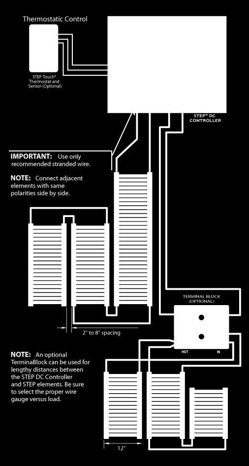
16 DC CONTROLLER WIRING DIAGRAM 16 P a g e


17 FAIL SAFE WIRING The Fail Safe Wiring method is used whenever there may be a risk of damaging the bus braids located on each side of the heating elements. Supplying electricity from both ends of an element eliminates the possibility of arcing from a damaged bus braid. Not only is this wiring method safer, it reduces voltage drop and makes the element more powerful. 17 P a g e
18 CONTROLS STEP TOUCH THEMOSTAT SPECIFICATIONS THERMOSTAT The STEP Touch thermostat can be used in conjunction with all the EPI-LX-R power supply series and the STEP DC Controllers Install the thermostat indoors. Measure the distance from the power supply to the thermostat to identify the length of the thermostat wire. The low-voltage (24V) thermostat is connected to the power supply using a 3-conductor cable and can control unlimited power supplies. EXTENAL SENSOR The external temperature sensor is installed in the concrete, in a conduit, between the heating elements. SETTINGS Set dip-switches in the back to snowmelt mode: Pos.1 (C ) or F : displays Celsius or Fahrenheit Pos.2 or DIM: display is lit or dimmed Pos.3 to EXT: displays the external temperature when an exterior temperature sensor is attached. Pos.4 to SM: snowmelt with remote external temperature sensor FUNCTION The STEP Touch thermostat collects temperature information every 1.5 second for 10 minutes before deciding to add or reduce heat. This cycle is repeated endlessly. OPERATION When the settings are done the thermostat is operated by two touch buttons only; up or down or press both buttons simultaneously to switch the system off. 18 P a g e
19 WARRANTY REGISTRATION AND COVERAGE LIMITED WARRANTY Electro Plastics limited warranty is valid from date of original purchase, as follows (not included in this warranty are OEM and specialty products): 20 years for the STEP Warmfloor Heating Elements. 10 years for the STEP Snowmelt and Deicing Heating Elements. 10 years for the STEP Transformer Coils in the Power Supplies. 3 years for the Interface Electronics in the Power Supplies. 3 years for the STEP Controls Electro Plastics sole obligation under its warranty shall be, at its option, to either issue a credit for the purchase price, or repair or replace any article or part thereof, which is proved to be other than as warranted. For this warranty to be valid, a copy of the STEP Labels shall be delivered to ELECTRO PLASTICS, INC., with a diagram indicating to which branch circuit the system is connected, the location of the element strips, the routing of the wires and their different measurements, voltage, amperage, elements and wire length. Electro Plastics warrants the products to be free from defects in material or manufacturing and to perform under normal use. For the warranty to be valid, qualified personnel who are familiar with the construction and operation of the system must install the equipment and a certified electrician has to verify and measure the STEP elements BEFORE they are covered. Exclusions Electro Plastics shall not be responsible for any loss or damage that may arise due to: Non-compliance with installation and/or usage of the STEP elements and accessories as recommended. It shall be Buyer s and End User s duty to read and follow carefully the STEP Installation Manual. Technical assistance services, e.g. design and layout are to be used as GUIDELINES ONLY, as each application is specific to local conditions and construction Dissatisfaction due to improper Installation of the floor covering. All floor covering shall be installed in conformance with the manufacturer s instructions and shall conform to all applicable trade practices, local codes and manufacturer's specifications. Usage of inadequate or non-specified materials with the STEP heating system or products. Any and all defects, deficiencies or failures resulting from improper handling of the product; e.g., cuts made to the STEP elements, or the wires, etc. Tampering with the STEP heating system or products; e.g., removing, altering or overloading the circuit breakers, overcurrent protectors, etc. Installation of merchandise with obvious visible defects. How to claim this warranty In order to obtain warranty service, Buyer shall return the unit to the dealer from whom the unit was originally purchased, with a dated sales receipt. The dealer will forward the unit to Electro Plastics. Upon receipt of the defective unit, paperwork and explanation of application, Electro Plastics will inspect and test the unit in order to determine the reason for the alleged failure. If it is determined that the unit was properly installed and failed during normal use, as a result of a manufacturing defect, Electro Plastic will repair or replace the unit, or issue a credit or refund of the purchase price, at its sole discretion. The warranty period for any replacement unit will fulfill the warranty of the original unit and will not be extended. 19 P a g e
20 WARRANTY REGISTRATION AND COVERAGE Limitations Under no circumstances will Electro Plastics be liable for labor or other charges related to the installation and use of the STEP heating system or products. This warranty does not cover labor or removal or reinstallation of the product and is void on any product installed improperly, or in an improper environment, overloaded, misused, abused or altered in any manner. THE WARRANTIES STATED HEREIN ARE EXCLUSIVE OF ALL OTHER WARRANTIES, WRITTEN OR ORAL, STATUTORY EXPRESS OR IMPLIED, INCLUDING ANY WARRANTIES OF MERCHANTABILITY AND FITNESS FOR A PARTICULAR PURPOSE, NONE OF WHICH SHALL APPLY TO THE SALE OF THE COMPANY'S PRODUCTS HEREUNDER. THIS WARRANTY ALSO EXCLUDES INCIDENTAL OR CONSEQUENTIAL DAMAGES FOR BREACH OF ANY WARRANTY ON THE PRODUCTS. Products which are replaced by Electro Plastics in accordance with the foregoing shall become the property of Electro Plastics and shall be returned to it by the purchaser f.o.b. point of shipment. The maximum liability of this warranty is limited to the replacement or repair or purchase price of the defective unit. If a unit is returned and found that no defect exists, or that the user misused the unit, Electro Plastics will inform the user. If the user chooses to have the unit repaired (if possible), labor and shipping charges will apply. Limitation of Liability ELECTRO PLASTICS SHALL NOT BE LIABLE FOR ANY LOSS, CLAIM, EXPENSE OR DAMAGE CAUSED BY, CONTRIBUTED TO OR ARISING OUT OF THE ACTS OR OMISSIONS OF BUYER OR THIRD PARTIES, WHETHER NEGLIGENT OR OTHERWISE, IN NO EVENT SHALL ELECTRO PLASTICS' LIABILITY FOR ANY CAUSE OF ACTION WHATSOEVER EXCEED THE COST OF THE PRODUCT GIVING RISE TO THE CLAIM, WHETHER BASED IN CONTRACT, WARRANTY, INDEMNITY OR TORT (INCLUDING NEGLIGENCE AND STRICT LIABILITY) OR OTHERWISE. IN NO EVENT SHALL ELECTRO PLASTICS BE LIABLE OR ANY SPECIAL, INCIDENTAL, CONSEQUENTIAL OR OTHER SUCH INDIRECT DAMAGES (INCLUDING, WITH-OUT LIMITATION, LOSS OF REVENUES, PROFITS OR OPPORTUNITIES), WHETHER ARISING OUT OF OR AS A RESULT OF BREACH OF CONTRACT, WARRANTY, TORT (INCLUDING NEGLIGENCE), STRICT LIABILITY OR OTHERWISE WARRANTY REGISTRATION CARD Ref. No.... CUSTOMER INFORMATION Owner s Name Address PURCHASE AND PROJECT INFORMATION Purchased From Date Address City / State / Zip Phone Product Purchased: Heating Elements Installed on : Heating Elements Installed under: Type of Project: Snowmelt Deicing Deck / Ramp Driveway Pathway Concrete Stone Other New Construction Renovation Project To activate warranty complete and return this warranty registration card signed with a complete checklist and layout showing element distribution as installed to: Dorsett Road, Maryland Heights, MO 63043, U.S.A. 20 P a g e
21 WARRANTY REGISTRATION AND COVERAGE CHECK LIST Ref. No.... Page... of... Temperature Control : Air Ground On/Off STEP Element Model No. : MEP- - W-24V Total Length Installed : Linear Feet Transformer Model No. : EPI-LX-R- W 120V 208V 230V MEASUREMENT INSTRUCTIONS Measure primary and secondary volts and amps at the transformer terminals. One sheet per transformer. Installed / measured by: Date: Name Signature 21 P a g e
22 TROUBLESHOOTING If the following procedures do not solve and relieve the problems encountered, please check with our Technical Service Department. POWER SUPPLY Problem: Solution: 1. Power Supply/DC Controller will not start: a) No current Reset circuit breaker in service panel and switch on line voltage branch circuit. b) Current is present Reset mini circuit breaker in power supply, push plunger in until it stays in. c) PC board in AC Power Supply / DC Controller has current Make sure the thermostat settings are correct and that the thermostat calls for heat. Set the temperature to maximum and wait a couple of minutes for the system to turn on. If this does not work, eliminate thermostat; disconnect thermostat cable from PCB (printed circuit board) and put a jump wire from terminal TRG to 24. The load active should now be lit and the system is on. The fault is in the thermostat cable or its connections. 2. Power Supply becomes hot: a) Poor ventilation Power Supply should be mounted vertical for the cooling fins to extract heat from the enclosure and it must be placed in a well-ventilated area. b) High voltage conditions A service technician can rewire 120V and 208V Power Supplies to accept higher voltage. Call customer service for guidance. c) High transformer temperature Power supply must be de-rated; decrease load. 22 P a g e
23 TROUBLESHOOTING HEATING ELEMENT Problem: Solution: 1. Insufficient temperature: a) Thermostat setting The thermostat is connected to an external sensor which is normally placed between the heating elements in the ground. Set temperature to about 40 o F. If snow is not melting increase the temperature and adjust to local conditions. It may take some snowfalls to find the minimum temperature at which snow is melting. b) A section is not melting snow Reset circuit breaker for this section. c) A strip is not melting snow Measure the volts and amps for this element at the terminal. If the voltage is correct and there is no amps the connection between the power supply and heating element is broken. If the voltage is correct and the amp reading is low the heating element has been damaged by chemicals or salt etc. If the element strip is partly melting snow while other parts on the same element length is cold the element is mechanically damaged. If electricity is not available at the time of trouble shooting disconnect the strip from the terminal and measure the resistance. Then call customer service for evaluation of the measurements. d) Low supply voltage Some regions or locations may have a low supply voltage and some may take electricity from sub-panels with reduced voltage. This results in a proportionally lower heat output. It is possible to boost up the voltage so the elements can pull more amps but this requires engineering. 23 P a g e


24 APPROVALS AND CERTIFICATIONS UL rd Edition UL & 2 CSA-C22.2 No & 2-06 EN EN : P a g e
STEP Warmfloor Installation Manual. Step Warmfloor Electric Radiant Floor Heating System
 STEP Warmfloor Installation Manual Step Warmfloor Electric Radiant Floor Heating System Contents INSTALLATION GUIDELINES... 3 IMPORTANT INSTALLATION GUIDLINES... 3 STEP WARMFLOOR HEATING SYSTEM... 3 BEFORE
Low Voltage System. STEP Warmfloor Installation Manual. Step Warmfloor Electric Radiant Floor Heating System
 Low Voltage System STEP Warmfloor Installation Manual Step Warmfloor Electric Radiant Floor Heating System Contents HEATING SYSTEM... 3 PRODUCT SPECIFICATIONS... 3 DESIGN AND CALCULATIONS... 3 SUPPLIED
Contents ATTACHING CONTROLS WARRANTY TOOLS... 5 ELEMENT ELEMENT POWER SUPPLY COVER HEATING ELEMENTS...
 STEP Roof Deicing Installation Manual STEP Deicing Syste em Contents STEP ROOF DEICING SYSTEM... 3 BENEFITS... 3 INSTALLATION GUIDELINES... 4 IMPORTANT INSTALLATION GUIDLINES... 4 WARNING... 4 BEFORE STARTING...
SECTION ELECTRIC FLOOR HEATING AND SNOW MELTING EQUIPMENT
 SECTION 15770 ELECTRIC FLOOR HEATING AND SNOW MELTING EQUIPMENT PART 1 GENERAL 1.1 SECTION INCLUDES A. Floor Heating Systems for the following applications: 1. Under Concrete. 2. Within Concrete. 3. Over
FloorHeat Installation Manual
 FloorHeat Installation Manual Transforming frosty floor surfaces into radiant warmth Transforming frosty floor surfaces into radiant warmth Contents Important Instructions!... 3 Safety Instructions:...
SECTION RADIANT-HEATING ELECTRIC CABLES PART 1 - GENERAL 1.1 SECTIONS INCLUDES
 SECTION 238313 - RADIANT-HEATING ELECTRIC CABLES PART 1 - GENERAL 1.1 SECTIONS INCLUDES A. Low-voltage Electric Snow and ice heating elements "under" finished roof materials (shingles or metal), gutters,
SECTION RADIANT-HEATING ELECTRIC CABLES / MATS
 SECTION 238313- RADIANT-HEATING ELECTRIC CABLES / MATS PART 1 - GENERAL 1.1 SECTION INCLUDES A. Electric radiant snow melting mats or cables embedded in concrete or asphalt slabs, or embedded under brick
Use this product according to this instruction manual. Please keep this instruction manual for future reference. MODELS: ST-H15-B & ST-H30
 273 Branchport Avenue Long Branch, N.J. 07740 (800) 631-2148 Thank you for using our products. www.wheelockinc. com INSTALLATION INSTRUCTIONS HORN SPEAKER WITH MULTI-TAP TRANSFORMER Use this product according
Classic Mats Installation Manual
 Classic Mats Installation Manual 1 Classic Mats WarmTouch Classic Mats are the ideal Electric floor warming systems, designed by DomoTecK, for installation under tile, stone or marble. WarmTouch Classic
Silicone Rubber Heating Tape with Adjustable Thermostat Control (HSTAT Series) Instruction Manual
 Instruction Manual") Silicone Rubber Heating Tape with Adjustable Thermostat Control (HSTAT Series) Instruction Manual Read and understand this material before operating or servicing these heating tapes. Failure to understand
Silicone Rubber Heating Tape with Adjustable Thermostat Control (HSTAT Series) Instruction Manual Read and understand this material before operating or servicing these heating tapes. Failure to understand
SEALING FIBER SEALING COMPOUND
 ARCTIC TRACE INSTALLATION INSTRUCTIONS Type GUAT26C Hazardous Location Power Connection and Butt Splice Kit for Temperature Limiting Submersible Heating Cable JUNCTION BOX SEALING FIBER SEAL OFF SEALING
F1202 TRACE HEATING. Road & Ramp
 Trace Heating Specialists Road & Ramp ROAD & RAMP HEATING ESH Trace Heating Ltd provide a comprehensive range of products to prevent the settlement of snow and formation of ice on roads, ramps and stairs.
Gardian W51. Approvals
 Gardian W51 120 V pre-assembled electric heating cables for pipe freeze protection and roof & gutter de-icing Installation Instructions Description Gardian W51 120 V pre-assembled self-regulating heating
Instruction Manual: IM E. Installation and Operation Manual for Powerware PVL 50, 80, 100, 120, 160, 200 KA
 Installation and Operation Manual for Powerware PVL 50, 80, 100, 120, 160, 200 KA Instruction Manual: For more information visit: www.eatonelectrical.com Effective: 01/06 PVL Page 2 Effective Date: 01/06
Figure 1. Figure 2. See notes 1 and 2 below.
 273 Branchport Avenue Long Branch, N.J. 07740 (800) 631-2148 Thank you for using our products. www.wheelockinc. com INSTALLATION INSTRUCTIONS HORN SPEAKER WITH AMPLIFIER Use this product according to this
Electric Floor Warming Systems Installation and Operation Instructions. Mat Heating Systems and Cable Heating Systems. UL Listed for USA and Canada
 Electric Floor Warming Systems Installation and Operation Instructions Mat Heating Systems and Cable Heating Systems UL Listed for USA and Canada Thank you for your purchase of a Warming Systems electric
Radiant Heat Film for Floating Floors
 Radiant Heat Film for Floating Floors INSTALLATION ANd operation INSTRUCTIONS For use under floating laminate, engineered wood, and floating tile flooring Cautions: THIS EQUIPMENT SHALL BE INSTALLED ONLY
(HSTAT Series) Instruction Manual
 Instruction Manual") Silicone Rubber Heating Tapes with Adjustable Thermostat Control (HSTAT Series) Instruction Manual Read and understand this material before operating or servicing these heating tapes. Failure to understand
Silicone Rubber Heating Tapes with Adjustable Thermostat Control (HSTAT Series) Instruction Manual Read and understand this material before operating or servicing these heating tapes. Failure to understand
Freezer Frost Heave Prevention
 Freezer Frost Heave Prevention 1. Pipe Freeze Protection and Flow Maintenance RaySol System Mineral Insulated Heating Cable System This step-by-step design guide provides the tools necessary to design
I.D.L. Heaters Thermal Products Ltd. Roll n Warm Installation Manual
 I.D.L. Heaters Thermal Products Ltd. Roll n Warm Installation Manual 0 The Most Luxurious and Safe System For Underfloor Heating Table of Contents Important Instructions 2 Safety Instructions 3 Before
Installation & Operation Manual
 Humidity & Temperature Sensor 086 Accessories 086_D 08/12 Replaces: New Installation & Operation Manual Introduction The Humidity & Temperature Sensor 086 can be connected to select tekmar thermostats
G Series SAVE THESE INSTRUCTIONS. (Model B) Convector Heater for Hazardous Locations GENERAL! INSTALLATION
 Convector Heater for Hazardous Locations GENERAL! INSTALLATION") G Series (Model B) Convector Heater for Hazardous Locations Type G-Series Convection Heaters are designed for use in Class I, Div. I hazardous environments. Units without control options are suitable for
G Series (Model B) Convector Heater for Hazardous Locations Type G-Series Convection Heaters are designed for use in Class I, Div. I hazardous environments. Units without control options are suitable for
Installation & Operation Manual
 Installation & Operation Manual Radiant Thermostat 519 519_D 06/16 Zoning Replaces: 03/13 Introduction The Radiant Thermostat 519 accurately controls the room and/or floor temperature for a hydronic heating
Installation Instructions
 Installation Instructions 3M Light Mat Series 3635-1000 Installation Bulletin 3635-1000 Release D, Effective July 2010 (Replaces C, Apr 2010) See Bulletin Change Summary at end of Bulletin Product Description
INSTALLATION. For more information on this product or to order samples call or visit our website at builddirect.com.
 Page 1 Page 2 Section 1. Introduction The Perfectly Warm Floating Floor Heat Heating System (PWF) is a unique heating system that is installed below floating flooring materials to create warm, comfortable
Radiant Thermostat 519
 106103_dl_02 Radiant Thermostat 519 Installation & Operation Manual Introduction The Radiant Thermostat 519 accurately controls the room and/or floor temperature for a hydronic heating zone using Pulse
Installation & Operation Manual
 519_D Radiant Thermostat 519 03/13 Zoning Replaces: New Installation & Operation Manual Introduction The Radiant Thermostat 519 accurately controls the room and/or floor temperature for a hydronic heating
- Data Brochure. This brochure is for Thermostats 510 and 511 (with sensor). The section on the 079 slab sensor installation is for the 511 only!
. The section on the 079 slab sensor installation is for the 511 only!") - Data Brochure Programmable Thermostat 510 and 511 D 510 02/12 Table of Contents Display / Keypad Operation... pg 1 Display Symbols... pg 2 General... pg 2-3 Sequence of Operation... pg 4 Installation
- Data Brochure Programmable Thermostat 510 and 511 D 510 02/12 Table of Contents Display / Keypad Operation... pg 1 Display Symbols... pg 2 General... pg 2-3 Sequence of Operation... pg 4 Installation
Surge Protective Devices Installation, Operation and Maintenance Manual. LowProfile Series: 080 and 120
 LowProfile Series: 080 and 120 Surge Protective Devices Installation, Operation and Maintenance Manual P.O. Box 3760 Winter Park, FL 32790 USA 1.800.647.1911 www.tpssurge.com LOWPROFILE InstaLLatIOn, OPERatIOn
FLCH4R Garage and Utility Electric Heater
 FLCH4R Garage and Utility Electric Heater Installation, Operation & Maintenance Instructions Model No. Volts Amps Watts BTU/HR Phase High Low High Low High Low Min Fuse Size* FLCH4R 208 17.3 8.66 3600
Always make sure to check the heating film before, during, and after installation of the floor covering.
 Installation of floor heating film for ceramic tiles, granite and other stone or composite flooring Read through this entire manual before starting installation. All electrical connections must be made
WATLOW IND. WATROD Modular Duct Heater Installation & Maintenance Manual I&M NUMBER: Page: 1 Date:6/11/2008 Rev: 2
 I&M NUMBER: 316-42-15-1 Page: 1 _ Pre Installation Check to make sure that heater received is the same as that ordered. Elements may come in contact with each other during shipment. Minor adjustments to
ADDITIONAL INFORMATION
 MODEL APS-3C AUTOMATIC SNOW/ICE MELTING SYSTEM CONTROL PANEL MODEL APS-4C AUTOMATIC SNOW/ICE MELTING SYSTEM CONTROL PANEL MODEL SC-40C MODULAR SNOW/ICE HEATER CONTROL SYSTEM SAFETY This device provides
CLIMAGUARD Air-to-Air Outdoor Heat Exchangers INSTRUCTION MANUAL. Rev. H 2015 Pentair Equipment Protection P/N
 CLIMAGUARD Air-to-Air Outdoor Heat Exchangers TX23, TX33, TX38, TX52 Model INSTRUCTION MANUAL Rev. H 2015 Pentair Equipment Protection P/N 10-1008-221 87976519 TABLE OF CONTENTS RECEIVING THE HEAT EXCHANGER...3
Sentry LIQUID LEVEL CONTROLLER MODEL 120 OPERATING MANUAL.
 Sentry LIQUID LEVEL CONTROLLER MODEL 120 OPERATING MANUAL www.aquaticsentry.com TABLE OF CONTENTS 1. SAFETY PRECAUTIONS... 3 2. APPLICATION... 3 2.1 HIGH AND LOW LEVEL ALARM 2.2 PUMP DOWN CONTROLLER 2.3
WATLOW IND. WATROD Circulation Heater Installation & Maintenance Manual I&M NUMBER: Page: 1 Date: 6/11/2008 Rev: 2.00
 I&M NUMBER: 316-42-5-1 Page: 1 Pre Installation Check to make sure that heater received is the same as that ordered. Watlow heaters are built to comply with UL and CSA dielectric requirements, it may be
Installation Manual NPE-180A/240A WARNING. Add-on Controller Installation Kit
 Installation Manual Add-on Controller Installation Kit NPE-180A/240A This device is designed to work with NPE-180A/240A models ONLY. WARNING All Installations should be done only by a qualified expert
MaxLite LED MICRO-T PANEL
 ` Installation Instructions General Safety Information To reduce the risk of death, personal injury or property damage from fire, electric shock, falling parts, cuts/abrasions, and other hazards read all
Keep your home snow and ice free with. WARMUP Outdoor Heating Solutions. From the world s best-selling electric floor heating brand
 Keep your home snow and ice free with WARMUP Outdoor Heating Solutions From the world s best-selling electric floor heating brand Applications for stairs for walkways for driveways for roofs & gutters
! The Caution Symbol (exclamation point) alerts you to a "CAUTION", a safety or
 alerts you to a CAUTION, a safety or") I&M NUMBER: 316-42-10-1 Page: 1 Pre Installation Check to make sure that heater received is the same as that ordered. Elements may come in contact with each other during shipment. Minor adjustments to
I&M NUMBER: 316-42-10-1 Page: 1 Pre Installation Check to make sure that heater received is the same as that ordered. Elements may come in contact with each other during shipment. Minor adjustments to
CurrentGuard TM. Installation, Operation and Maintenance Manual. CurrentGuardTM. Flush Mount. Surge Protective Devices A00
 TM CGFS u r g e P R O T E C T I O N CurrentGuardTM Installation, Operation and Maintenance Manual 750-0098-006 A00 Surge Protective Devices CurrentGuard TM Flush Mount Table of Contents Guide to Installation
Installation Manual WARNING. Add-on Controller Installation Kit NPE-180A/210A/240A
 Installation Manual Add-on Controller Installation Kit NPE-180A/210A/240A This device is designed to work with NPE-180A/210A/240A water heaters ONLY. WARNING All Installations should be done only by a
ES2-HB. Ordering Information. Dimensions. Specifications. Humidity Sensor Temperature/Humidity Sensor
 Humidity Sensor Temperature/Humidity Sensor ES2-THB CSM ES2-THB_DS_E_3_2 Detect Humidity within an Accuracy of ±3% in a Compact Body. Set Provides Superior Humidity Control and Temperature/ Humidity Control.
I.D.L. Heaters Thermal Products Ltd. IdealMat Installation Manual
 I.D.L. Heaters Thermal Products Ltd. IdealMat Installation Manual 0 1 The Most Luxurious and Safe System For Underfloor Heating Table of Contents Important Instructions 3 Safety Instructions 4 Before Starting
OCH-SS series Direct Wired Units Indoor * and Outdoor Comfort Heaters
 1200 North Main Street Fostoria, OH 44830 Phone: 800-495-4525 Fax: 419-435-0842 A DIVISION OF www.fostoriaindustries.com OCH-SS series Direct Wired Units Indoor * and Outdoor Comfort Heaters *EXCLUDING
Installation, Operation & Service Manual
 Installation, Operation & Service Manual WARNING Improper installation, adjustment, alteration, service or maintenance can result in death, injury or property damage. Read the Installation, Operation and
ALL-WEATHER LANDSCAPE BURIAL SUBWOOFERS Burial Subwoofers: 10 & 12 (250mm & 300mm)
") ALL-WEATHER LANDSCAPE BURIAL SUBWOOFERS Burial Subwoofers: 10 & 12 (250mm & 300mm) CONTENTS 10 Burial Subwoofer: (1) Burial Subwoofer with Direct Burial Cable Attached (2) Silicone-Filled Wire Connectors
ALL-WEATHER LANDSCAPE BURIAL SUBWOOFERS Burial Subwoofers: 10 & 12 (250mm & 300mm) CONTENTS 10 Burial Subwoofer: (1) Burial Subwoofer with Direct Burial Cable Attached (2) Silicone-Filled Wire Connectors
GG-EM ENTRANCE MONITOR. Installation and Operation Manual
 GG-EM ENTRANCE MONITOR Installation and Operation Manual 2 GG-EM Warning Use this product only in the manner described in this manual. If the equipment is used in a manner not specified by Calibration
IMPORTANT INSTRUCTIONS
 IMPORTANT INSTRUCTIONS W Fan Force Electric Space Heater DANGER ELECTRIC SHOCK OR FIRE HAZARD Figure 1 Covers all W Series models WARNING Read Carefully - These instructions are written in an effort to
SPA BLOWER OWNER'S MANUAL XXXX, XXXX, XXXX, XXXX, XXXX, XXXX fax
 SPA BLOWER OWNER'S MANUAL 80015-XXXX, 80016-XXXX, 80017-XXXX, 80018-XXXX, 80019-XXXX, 80020-XXXX fax 888.610.3839 2015 323300-015 6/15 THIS PAGE INTENTIONALLY LEFT BLANK. 2 Operating Instructions and Parts
WATLOW IND. WATROD Flange Heater Installation & Maintenance Manual I&M NUMBER: Page: 1 Date:6/11/2008 Rev: 2.00
 I&M NUMBER: 316-42-8-1 Page: 1 _ Pre Installation Check to make sure that heater received is the same as that ordered. Elements may come in contact with each other during shipment. Minor adjustments to
INSTALLATION INSTRUCTIONS MODEL PA-250 AND PA-500 BOOSTER AMPLIFIER
 273 Branchport Avenue Long Branch, N.J. 07740 (908) 222-6880 INSTALLATION INSTRUCTIONS MODEL PA-250 AND PA-500 BOOSTER AMPLIFIER GENERAL: The Series PA-250 and PA-500 Watt Booster Amplifiers are designed
ELECTRIC FIREPLACE HEATER WITH SINGLE GLASS DOOR
 ELECTRIC FIREPLACE HEATER WITH SINGLE GLASS DOOR Model 91797 ASSEMBLY and Operating Instructions Visit our website at: http://www.harborfreight.com Read this material before using this product. Failure
Carbon Heating Film. Failure to follow these instructions may result in fire, electrical shock, property damage, personal injury, or death.
 Carbon Heating Film Easy to install. Does not circulate pollutants, dust, dirt, allergens or dry air. May be installed on wall, ceiling, under laminate, engineered wood floors or tile. Brings soothing
R Series B & T2 Model
 FRONT R Series B & T2 Model Fan Forced Wall Heaters 4-1/4 (108mm) NOTE: Knockouts in top same dimensions 3-1/4 3-1/4 (108mm) (108mm) as bottom 16-7/8 (429mm) 13-7/8 (352mm) BOTTOM 13-7/8 (352mm) 7-3/4
OCH-SSE series Direct Wired Units Indoor * and Outdoor Comfort Heaters
 TPI Corporation P.O. Box 4973 Johnson City, TN 37601 www.tpicorp.com OCH-SSE series Direct Wired Units Indoor * and Outdoor Comfort Heaters *EXCLUDING RESIDENCES IMPORTANT SAFETY INFORMATION INSIDE possible
Underwood Heater Installation Manual
 Underwood Heater Installation Manual Contents Important Safeguards and Warnings... 3 1 General Information... 3 1.1 Use of the Manual... 3 1.2 Safety Guidelines... 3 1.3 Remember to measure resistance...
WATLOW ELECTRIC MFG CO. WATROD Duct Heater (module only) I& M Manual I&M NUMBER: Page: 1 Date: 11/25/2013 Rev: 4.00
 I& M Manual I&M NUMBER: Page: 1 Date: 11/25/2013 Rev: 4.00") I&M NUMBER: 316-42-16-1 Page: 1 Pre Installation Check to make sure that heater received is the same as that ordered. Elements may come in contact with each other during shipment. Minor adjustments to
I&M NUMBER: 316-42-16-1 Page: 1 Pre Installation Check to make sure that heater received is the same as that ordered. Elements may come in contact with each other during shipment. Minor adjustments to
WATLOW IND. FIREBAR Flange Heater Installation & Maintenance Manual I&M NUMBER: Page: 1 Date: 6/11/2008 Rev: 2.00
 I&M NUMBER: 316-42-2-1 Page: 1 Pre Installation Check to make sure that heater received is the same as that ordered. Elements may come in contact with each other during shipment. Minor adjustments to elements
HotPoly Tote Tank / IBC Heaters (TTH Series)
") HotPoly Tote Tank / IBC Heaters (TTH Series) Instruction Manual Read and understand this material before operating or servicing these heaters. Failure to understand how to safely operate these heaters
HotPoly Tote Tank / IBC Heaters (TTH Series) Instruction Manual Read and understand this material before operating or servicing these heaters. Failure to understand how to safely operate these heaters
SAVE THESE INSTRUCTIONS
 Important Safety Instructions When using this electrical equipment, basic safety precautions should always be followed, including the following: 1. READ AND FOLLOW ALL INSTRUCTIONS. 2. This appliance must
Warm Feet For Uncoupling Membrane Pour membrane de désolidarisation. Installation Guide Floor Heating Cable
 Warm Feet For Uncoupling Membrane Pour membrane de désolidarisation Installation Guide Floor Heating Cable 119A Sir Wilfrid Laurier Saint-Basile-le-Grand, (Québec), J3N 1M2 Tel: 1-450-482-1919 Toll Free:
Com-Pak Heater Benefits You Can Depend On Com-Pak Models Line Model w/o Model w/ Voltage Thermostat Thermostat Watts Amps (1) (2)
 (2)") Benefits You Can Depend On Dual safety features Primary: power reset thermal switch Secondary: over temperature thermal fuse Heating element style quickly warms your room, and quickly cools when heater
Benefits You Can Depend On Dual safety features Primary: power reset thermal switch Secondary: over temperature thermal fuse Heating element style quickly warms your room, and quickly cools when heater
The Da-Lite Difference.
 The Da-Lite Difference. Instruction Book for senior Electrol DA-LITE SCREEN COMPANY, INC. 100 North Detroit Street Post Office Box 17 Warsaw, Indiana 46581-017 Phone: 574-267-8101 800-622-77 Fax: 574-267-7804
Installation and Owner Man u al
 T H R E E P H A S E Evaporator Fan Control System Installation and Owner Man u al WARNING The installation of this device should be done only by competent personnel, experienced in electrical wiring, and
Ion Genesis II Pump Controller Digital Level Control with Pump Alternation and High Water Alarm
 Page 1 of 8 General Overview Thank you for purchasing an Ion Genesis controller. Take the time to read the instructions carefully before using this appliance. We strongly recommend that you keep this instruction
ALL WEATHER SL-SERIES QUARTZ TUBE ELECTRIC INFRARED RADIANT HEATER INSTALLATION USE & CARE MANUAL
 ALL WEATHER SL-SERIES QUARTZ TUBE ELECTRIC INFRARED RADIANT HEATER TABLE OF CONTENTS: INSTALLATION USE & CARE MANUAL IMPORTANT INFORMATION Assembly Instructions 2 Wiring Instructions 2 Outdoor Installation
Quick Set-up Guide. 1. Location 2. Remove Mounting Base. 4. Switch Settings. 3. Install Mounting Base. 5. Wiring. Snow Melting Control PM-653
 Quick Set-up Guide Snow Melting Control PM-653 1. Location 2. Remove Mounting Base Interior Wall Behind Door 5 feet 1.5 m Exterior Wall 3. Install Mounting Base 4. Switch Settings Base 3 ¼" (83 mm) Stud
OPERATION & INSTALLATION MANUAL
 OPERATION & INSTALLATION MANUAL Model: SIO 14 & SIO 18 Electric Tankless Hot Water Generators Table of Contents SAFETY INFORMATION... 1 INTRODUCTION... 2 Unit Operation:... 2 Unit Freezing:... 3 Maintenance:...
IN-GROUND SUBWOOFER INSTRUCTION MANUAL LS12T SUB LS15T SUB
 IN-GROUND SUBWOOFER INSTRUCTION MANUAL LS12T SUB LS15T SUB Introduction Thank you for purchasing a SLS Subwoofer. When properly installed, this subwoofer will provide you with years of outdoor entertainment
FOSTORIA INDUSTRIES, INC North Main Street Fostoria, OH Phone: Fax:
 A DIVISION OF FOSTORIA INDUSTRIES, INC. 1200 North Main Street Fostoria, OH 44830-1911 Phone: 800-495-4525 Fax: 419-435-0842 www.fostoriaindustries.com VHC-32 Variable Heat Controller for 222 MUL-T-MOUNT
Snow melting for ramps, access ways, and footpaths
 Snow melting for ramps, access ways, and footpaths Ice and snow on paths, loading bays, driveways, ramps, stairs and other access ways, can present a major problem causing accidents and delays. To help
Blade Series Heat Exchanger Operation and Installation
 Blade Series Heat Exchanger Operation and Installation *IMPORTANT* For safe and satisfactory operation, please read the following instructions. Keep these instructions for future reference. Some information
MaxLite LED VAPOR TIGHT LINEAR FIXTURES
 A cost effective LED Vapor Tight Fixture features a full length polycarbonate lens and a one-piece white glass reinforced polyester (GRP) body. Designed to meet or exceed seven to 10 foot-candles at 8
Underfloor Heating Cable Installation Manual
 Affordable Underfloor Heating Underfloor Heating Cable Installation Manual Technical Helpline 0845 034 8272 www.sunstone.co.uk SunStone Wire Manual V3.1.indd 1 09/01/2015 14:00:49 BEFORE YOU BEGIN INSTALLATION...
Ion Endeavor Pump Controller Digital Level Control with Pump Alternation and High Water Alarm
 Ion Endeavor Controller Digital Level Control with Alternation Page 1 of 8 General Overview The Ion Endeavor is a pump controller that senses a water level of up to 72", has a configurable water level/pump
Sentry LIQUID LEVEL GAUGE MODEL 200 or 200C OWNER MANUAL REV 1.7 SEPT08 PAGE 1 OF 12
 PAGE 1 OF 12 TABLE OF CONTENTS PAGE 1. SAFETY PRECAUTIONS 1.1. Electrical shock 3 2. APPLICATION 3 3. INSTALLATION 3.1. Mount indoor alarm display 3.2. Mount the outdoor junction box 3.3. Install interconnecting
WKS 4000 SERIES (USA only) --INSTALLATION INSTRUCTIONS--
 --INSTALLATION INSTRUCTIONS--") 8610 Production Avenue San Diego, California 92121 (858) 566-7465 Fax (858) 566-1943 WKS 4000 SERIES (USA only) --INSTALLATION INSTRUCTIONS-- Thank you for choosing a BREEZAIRE cooling unit. We believe
8610 Production Avenue San Diego, California 92121 (858) 566-7465 Fax (858) 566-1943 WKS 4000 SERIES (USA only) --INSTALLATION INSTRUCTIONS-- Thank you for choosing a BREEZAIRE cooling unit. We believe
TORRID MARINE YACHT QUALITY Since Owner s Manual
 Marine Water Heaters Owner s Manual Plumbing Configuration Note: While Torrid Marine is always happy to offer advice, we highly recommend you choose a professional marine technician to install your new
GG-VL-R REFRIGERANT VENT LINE SENSOR. Installation and Operation Manual
 GG-VL-R REFRIGERANT VENT LINE SENSOR Installation and Operation Manual 2 GG-VL-R Warning Use this product only in the manner described in this manual. If the equipment is used in a manner not specified
WATLOW ELECTRIC MFG CO. FIREBAR Screw Plug Installation & Maintenance Manual I&M NUMBER: Page: 1 Date: 11/25/2013 Rev: 4.
 I&M NUMBER: 316-42-3-1 Page: 1 Pre Installation Check to make sure that heater received is the same as that ordered. Elements may come in contact with each other during shipment. Minor adjustments to elements
CPL Series Pedestal Convection Heater
 Installation Instructions and RENEWAL PARTS IDENTIFICATION CPL Series Pedestal Convection Heater MODEL CPLAS (H=5-1/2, D=3 ) CAT. LENGTH WATTS/ TOTAL AMPERAGE NO.* L Ft. WATTS 120V 208V 240V 277V 2125
Single Phase Simplex SXL21=3, SXL24=3, SXH21=3, and SXH24=3
 Single Phase Simplex SXL21=3, SXL24=3, SXH21=3, and SXH24=3 Manufactured by SJE-Rhombus Installation Instructions and Operation/Troubleshooting Manual 7000 Apple Tree Avenue Bergen, New York 14416 Phone:
Single Point Freeze Protection Heat Trace Control TRACON MODEL FPT 130 Installation and Operation Manual
 We manage heat MANUAL Single Point Freeze Protection Heat Trace Control TRACON MODEL FPT 130 Installation and Operation Manual 1850 N Sheridan Street South Bend, Indiana 46628 (574) 233-1202 or (800) 234-4239
Use this product according to this instruction manual. Please keep this instruction manual for future reference.
 273 Branchport Avenue Long Branch, NJ 07740 (732) 222-6880 Thank you for using our products. INSTALLATION INSTRUCTIONS REMOTE MICROPHONE (SINGLE CIRCUIT) Use this product according to this instruction
ELEKTRA RadiantFloor Heating
 www.elektra.eu ELEKTRA RadiantFloor Heating single-side powered MD Heating Mats Installation manual ELEKTRA Heating Mats For the proper installation and operation of the ELEKTRA radiant floor heating system,
5+2 DAY. Digital Thermostat. residential. & 1-cool. up to 2-heat PROGRAMMABLE THERMOSTAT. Venstar Inc. 05/08
 Digital Thermostat residential THERMOSTAT 5+2 DAY PROGRAMMABLE up to 2-heat & 1-cool HEAT PUMP Stages: 2-Heat, 1-Cool Battery or System Powered Auxiliary Heat Indicator Back-Lit Digital Display Fahrenheit
XT Series Thermostats
 ISO 9001 Explosion-Proof & Moisture Resistant XT Series Thermostats Installation, Operation, & Maintenance Instructions XTWA Thermostat XTWL Thermostat XTB Thermostat Part No.MI133.Rev.2.00 Date of Issue:
IMPORTANT NOTES. Electric Underfloor Heating Mats For use with Touchsceen underfloor heating Thermostat
 For any assistance or further information, go online at bathstore.com Electric Underfloor Heating Mats For use with Touchsceen underfloor heating Thermostat - 61000012339 Model Dimensions Area Covered
Warnings 2. Installation Instructions 3. Wiring Instructions 3. Mounting Instructions 4. Replacement Element Installation 5. Replacement Parts 5
 TABLE OF CONTENTS Warnings 2 Installation Instructions 3 Wiring Instructions 3 Mounting Instructions 4 Replacement Element Installation 5 Replacement Parts 5 Heater Coverage Areas 6 General Notes 6 Maintenance
WMWLB / WMWFM / WTWLB / WTWFM Series Hydronic Heating Unit
 January 2008 WMWLB / WMWFM / WTWLB / WTWFM Series Hydronic Heating Unit Installation Operation Maintenance The units are designed for permanent up flow, counter flow, or horizontal left or right airflow
Warnings 2. Installation Instructions 3. Wiring Instructions 3. Mounting Instructions 4-5. Replacement Element Installation 5. Replacement Parts 5-6
 TABLE OF CONTENTS Warnings 2 Installation Instructions 3 Wiring Instructions 3 Mounting Instructions 4-5 Replacement Element Installation 5 Replacement Parts 5-6 Heater Coverage Areas 6 General Notes 6
GASGUARD LEL 3 OPERATING & INSTALLATION MANUAL
 GASGUARD LEL 3 Ammonia Sensor OPERATING & INSTALLATION MANUAL GasGuard LEL 3 Operating and Installation Manual 2 Table of Contents 3GasGuard LEL Operating and Instruction Manual General description. 4
The DEF-System by BRUGG. The Best Way to defeat the problem of DEF heat Installation Instructions
 The -System by BRUGG The Best Way to defeat the problem of heat Installation Instructions -System Installation Instructions Content Page 3 Page 4 Page 5 Page 6 Page 7 Description of System Installation
INSTALLATION USE & CARE MANUAL ALL WEATHER SL-SERIES QUARTZ TUBE ELECTRIC INFRARED RADIANT HEATER
 INSTALLATION USE & CARE MANUAL ALL WEATHER SL-SERIES QUARTZ TUBE ELECTRIC INFRARED RADIANT HEATER TABLE OF CONTENTS IMPORTANT INFORMATION Warnings 2 Installation Instructions 3 Wiring Instructions 3 Outdoor
SPA HEATER INSTALLATION, OPERATION AND MAINTENANCE
 SPA INSTALLATION, OPERATION AND MAINTENANCE MODELS: ST SERIES 5.5 & 11kW 240V SINGLE PHASE BEFORE YOU BEGIN CHECK ALL ELECTRICAL CONNECTIONS TO ALL COMPONENTS WITHIN THE FOR TIGHTNESS. CONNECTIONS CAN
SSC-1D installation guide
 Phason The Single Stage Control (SSC-1D) automatically controls the temperature in a room by switching fans, lamps, or heaters on or off as the temperature drops below or exceeds the temperature set point.
Toll Free:
 1 ProLine s electric radiant floor heating system is one of the most popular and durable floor heating solutions on the market. Available pre-spaced in mats with an adhesive backing or on the spool, the
* These Remote Mics must be SPRM-GP
 273 Branchport Avenue Long Branch, NJ 07740 (800) 6312148 Thank you for using our products. www.coopernotification.com INSTALLATION INSTRUCTIONS REMOTE MICROPHONE EXPANSION MODULE Use this product according
Hazardgard. Product Profile. Engineered to perform in the harshest environments. Hazardous Location Room Air Conditioners
 Product Profile Hazardgard Engineered to perform in the harshest environments Features Hazardous Location Room Air Conditioners Permanent split capacitor motor Hermetically sealed refrigeration system