Pluggit iconvent Decentralized residential ventilation with heat recovery Operating and installation instructions
|
|
|
- Edgar Shields
- 5 years ago
- Views:
Transcription


1 git iconvent Decentralized residential ventilation with heat recovery Operating and installation instructions
2 The technology makes the difference. Innovations of git with an added value for the human being and environment. Q The Q-ventilation typical for PLUGGIT room systems guarantees efficiency and comfort for the distribution of supply air. The first Q - the displacement ventilation - distributes the fresh air very slowly without any background noises and draughts in the room. The second Q - the cross ventilation - causes a complete air flow of the room. In this, the fresh air outlet in the outside wall area is positioned as far away as possible from the door of the supply air room. The special PLUGGIT iqoanda-air outlet is positioned above the access of the supply air room, if possible. The Qoanda effect leads the air flow along the ceiling in the furthest corner of the room. By means of this type of flow a comprehensive air quality is ensured without any background noises and draughts. allfloor ServoFlow The distribution systems of PLUGGIT allow an installation of pipe systems at all three installation levels. For new buildings or renovation the ventilation ducts can be assembled safely and easily: in the insulating layer of the floor, in the bare concrete of the ceiling or below the ceiling. The innovative and unique PLUGGIT ServoFlow-technology guarantees the supply of utilization-oriented air volume for a building at any time. Above all, it ensures the important balance of supply and exhaust air flows by means of an automatically conducted calibration once a week and documents modifications, like the filter contamination in the plant. The energy efficiency of ventilation units is defined by two factors. The high heat recovery of our ventilation units ensures low heat losses and comfortable supply air temperatures. Decisive, however, is the power consumption. By means of highly efficient direct current vans the operating costs are reduced to a minimum. Thus, the ratio of heat recovery and power consumption, which means the efficiency, is the most significant value and is defined as coefficient of performance. At the coefficients of performance PLUGGIT ventilation units achieve maximum values of up to and thus guarantee an excellent energy efficiency. CleanSafe CleanSafe stands for an easy cleaning. As a first company PLUGGIT had a cleaning system certified which facilitates cost-effective cleaning and maintenance of all system components, whether a round tube or a shallow duct distribution system is installed. Fresh air and heat supply in one system - faster, more flexible and more energysaving than common heating systems. Perfect feel-good climate by means of optimal air humidity in the room air with the air humidifier AeroFresh.
3 TABLE OF CONTENTS. General safety instructions.... General notes..... Appropriate use..... Non-appropriate use..... Warranty.... Overview..... Single-room ventilation unit iconvent Mono..... Single-room ventilation unit iconvent Duo.... Function/principle..... Single-room ventilation unit iconvent Duo..... Single-room ventilation unit iconvent Mono Cross ventilation Installation type single-room ventilation unit iconvent Duo Installation type single-room ventilation unit iconvent Mono and iconvent Duo Installation type single-room ventilation unit iconvent Duo and exhaust air van Installation type single-room ventilation unit iconvent Mono, iconvent Duo and exhaust air van Regulation Regulation schemes Time-delay relay Connection diagram Technical data Measurements.... Installation (qualified staff)..... Notes for installation..... Assemble installation stone ICVS and installation sleeve ICVH Installation stone ICVS for single-room ventilation unit iconvent Mono Installation stone ICVS for single-room ventilation unit iconvent Duo Installation sleeve ICVH for single-room ventilation unit iconvent Mono Installation sleeve ICVH for single-room ventilation unit iconvent Duo..... Install single-room ventilation unit..... Initial operation... 7 BIA Single room ventilation unit iconvent Mono and iconvent Duo
4 .. Technical data Unit data Regulation Measurements Basic wiring diagram, electrical Operation (user)..... Overview regulation..... Increase/ reduce fan level..... Reset filter alarm..... Error correction Disturbances Maintenance (user) Clean inside panel Clean ceramic heat exchanger Clean/ change filter Decommissioning/disposal Decommissioning at extension Packaging Old unit... BIA Single room ventilation unit iconvent Mono and iconvent Duo
5 . GENERAL SAFETY INSTRUCTIONS. GENERAL NOTES Warning: The following safety instructions shall be noted, otherwise injuries or damages can be implied: Before you begin with the installation and operation of the decentralized single-room ventilation unit, carefully read these operation and installation instructions. The installation and all electrical works shall only be carried out by qualified staff. Consider all necessary legal and national standards (accident prevention regulations and acknowledged rules of technology) for the installation and initial operation of the decentralized single-room ventilation unit and observe them. Damages which occur due to product-inappropriate storage, improper operation and installation or non-appropriate use are excluded from each kind of liability. Subject to technical changes... APPROPRIATE USE The decentralized single-room ventilation unit iconvent Mono and iconvent Duo serve as regulated aeration and ventilation of individual supply air rooms, for example, living rooms and children's rooms as well as exhaust air rooms, for example, kitchen and bathroom with window in accordance with DIBt-approval... NON-APPROPRIATE USE Other uses of the decentralized single-room ventilation unit than those described under "appropriate use" are inadmissible. The decentralized single-room ventilation unit shall not be applied for construction drying... WARRANTY For a full legal warranty claim the technical standards of these operating and installation instructions shall be observed. BIA Single room ventilation unit iconvent Mono and iconvent Duo
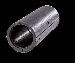
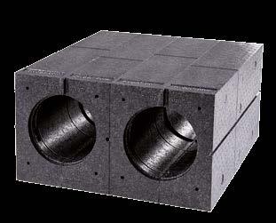
6 . OVERVIEW.. SINGLE-ROOM VENTILATION UNIT ICONVENT MONO 7.. git iconvent inside panel Mono ICVM-B Base plate, inside git iconvent functional unit ICVF. git iconvent installation stone ICVS. git iconvent installation sleeve ICVH Base plate, outside Insulation mat 7 git iconvent weather protection grid Mono ICVM-WSG M+P-A-0 Depending on the construction plan the git iconvent installation sleeve ICVH (.) can also be used instead of the git iconvent installation stone ICVS (.). This is designed as round EPP sleeve 98 mm. BIA Single room ventilation unit iconvent Mono and iconvent Duo
7 .. SINGLE-ROOM VENTILATION UNIT ICONVENT DUO.. 7 git iconvent inside panel Duo ICVD-B Base plate, inside git iconvent functional unit ICVF. git iconvent installation stone ICVS. git iconvent installation sleeve ICVH Base plate, outside Insulation mat 7 git iconvent weather protection grid Duo ICVD-WSG M+P-A-0 Depending on the construction plan the git iconvent installation sleeve ICVH (.) can also be used instead of the git iconvent installation stone ICVS (.). This is designed as round EPP sleeve 98 mm. BIA Single room ventilation unit iconvent Mono and iconvent Duo
8 . FUNCTION/PRINCIPLE.. SINGLE-ROOM VENTILATION UNIT ICONVENT DUO Rotation direction A Rotation direction B Outside wall Outside wall up up down Inside wall M+P-A-0 down Inside wall M+P-A-0 Single-room ventilation unit iconvent Duo Single-room ventilation unit iconvent Duo Functional unit supply air operation Functional unit supply air operation Supply air Supply air Functional unit exhaust air operation Functional unit exhaust air operation Exhaust air Exhaust air For the hygienically necessary exchange of air outside air is fed into the functional unit () of the single-room ventilation unit () and transported in the living room as supply air (). Humid and used exhaust air () is discharged through the functional unit () out of the building. Approximately each 80 seconds the rotation direction of the fans in the functional units () and () is changed. This way, also the direction of supply air () and exhaust air () is changed. The ceramic heat exchanger of the functional unit () is heated by the inside room temperature. This heat is supplied at the change of rotation direction of the supply air (). Due to this operation a permanent heat recovery is achieved. BIA Single room ventilation unit iconvent Mono and iconvent Duo
9 .. SINGLE-ROOM VENTILATION UNIT ICONVENT MONO Rotation direction A Rotation direction B Outside wall Outside wall up up Inside wall down M+P-A-07 Inside wall down M+P-A-08 Single-room ventilation unit iconvent Mono Single-room ventilation unit iconvent Mono Functional unit supply air operation Functional unit exhaust air operation Supply air Exhaust air The change of rotation direction of the fan in the singleroom ventilation unit iconvent Mono () is carried out correspondingly as in the single-room ventilation unit iconvent Duo. The single-room ventilation units iconvent Mono () shall be operated in pairs for a regulation. This means one unit runs in supply air operation whereas the second unit simultaneously runs in exhaust air operation. The change of rotation direction is also conducted simultaneously in pairs. Only this way the balance between supply and exhaust air volume stream required according to DIN 9- and DIBt-approval can be guaranteed. BIA Single room ventilation unit iconvent Mono and iconvent Duo 7
10 .. CROSS VENTILATION +% +% +% +/-0% +/-0% +% Sample installation Single-room ventilation units Regulation Cross ventilation Supply air room, for example, living room and dining room Supply air room, for example, bedroom Supply air room, for example, guest room 7 Supply air room, for example, bathroom with window 8 Exhaust air room, for example, kitchen with window 9 Overflow area, for example, corridor or hall Thus the single-room ventilation units () can be controlled by the regulation (), so that a sufficient cross ventilation () of the entire utilization unit is guaranteed. For the realisation of cross ventilation () the supply air volume flows in this sample installation, for example, in the living room and dining room (), must be increased by + %. In the opposite rooms, for example, in the bedroom () and guest rooms (), the exhaust air volume flows must by higher by + %. Additionally suitable overflow openings, for example, door undercuts are necessary. In exhaust air rooms with windows, for example, bathroom (7) and kitchen (8), no cross ventilation is necessary. Here the single-room ventilation units () must be operated in balance according to the DIBt-approval. This means they run independently with regard to air technology, independent from the settings of the supply air rooms. In such a case either two single-room ventilation units iconvent Mono or one single-room ventilation unit iconvent Duo must be installed. In the overflow sector, for example, corridor or hall (9), an own single-room ventilation unit can be renounced, because, as a rule, the cross ventilation () is sufficient, in order to achieve a sufficient air exchange in these rooms. M+P-A-0 8 BIA Single room ventilation unit iconvent Mono and iconvent Duo
11 .. INSTALLATION TYPE SINGLE-ROOM VENTILATION UNIT ICONVENT DUO The described installation type is valid for bathrooms with integrated window. +% +% +% +/-0% +/-0% +% Sample installation Single-room ventilation unit iconvent Duo Regulation Cross ventilation Supply air room, for example, living and dining room Supply air room, for example, bedroom Supply air room, for example, guest room or children's room 7 Exhaust air room, for example, bathroom with window 8 Exhaust air room, for example, kitchen with window 9 Overflow area, for example, corridor or hall M+P-A-0 BIA Single room ventilation unit iconvent Mono and iconvent Duo 9
12 .. INSTALLATION TYPE SINGLE-ROOM VENTILATION UNIT ICONVENT MONO AND ICONVENT DUO The described installation type is valid for bathrooms with integrated window. +/-0% +/-0% Sample installation Single-room ventilation unit iconvent Mono Single-room ventilation unit iconvent Duo Regulation Supply air room, for example, living and dining room Supply air room, for example, bedroom Supply air room, for example guest room or children's room 7 Exhaust air room, for example, bathroom with window 8 Exhaust air room, for example, kitchen with window 9 Overflow area, for example, corridor or hall M+P-A-0 0 BIA Single room ventilation unit iconvent Mono and iconvent Duo
13 .. INSTALLATION TYPE SINGLE-ROOM VENTILATION UNIT ICONVENT DUO AND EXHAUST AIR VAN The described installation type is valid for inside bathrooms without window according to DIN m /h +m /h +m /h +/-0% VAB = 0m /h +m /h Sample installation Single-room ventilation unit iconvent Duo Exhaust air fan according to DIN 807- Regulation Supply air room, for example, living and dining room Supply air room, for example, bedroom Supply air room, for example, guest room or children's room 7 Exhaust air room, for example, bathroom without window 8 Exhaust air room, for example, kitchen with window 9 Overflow area, for example, corridor or hall In flats with an inside bathroom without window (7) an exhaust air fan () must be installed according to DIN This has to generate an exhaust air volume flow of 0 m³/h (V AB ) To realize a balanced air exchange additional volume flows must be generated in the supply air rooms, which balance the air volume flow of the exhaust air fan. Only this way it can be ensured that there is no vacuum in the utilization unit and the single-room ventilation units () which are in exhaust air operation can continue to generate heat recovery. Example: The exhaust air fan () is connected with two regulations () of supply air rooms, as it is described here. The supply air volume flow of the single-room ventilation units () must be adjusted respectively + m³/h higher in the supply air operation. By this, in total the 0 m³/h exhaust air volume flow of the exhaust air fan () is compensated. The single-room ventilation unit () in the kitchen (8) continues to run in balance. BIA Single room ventilation unit iconvent Mono and iconvent Duo M+P-A-07
14 .7. INSTALLATION TYPE SINGLE-ROOM VENTILATION UNIT ICONVENT MONO, ICONVENT DUO AND EXHAUST AIR VAN The described installation type is valid for inside bathrooms without window according to DIN m /h +0m /h 7 +/-0% VAB = 0m /h Sample installation Single-room ventilation unit iconvent Mono Single-room ventilation unit iconvent Duo Exhaust air fan according to DIN 807- Regulation Supply air room, for example, living and dining room Supply air room, for example, bedroom 7 Supply air room, for example, guest room or children's room 8 Exhaust air room, for example, bathroom without window 9 Exhaust air room, for example kitchen with window 0 Overflow area, for example, corridor or hall The installation type with single-room ventilation unit iconvent Mono (), iconvent Duo () and exhaust air fan () is carried out correspondingly. BIA Single room ventilation unit iconvent Mono and iconvent Duo M+P-A-08 Example: The exhaust air fan () is also connected with the regulation (), which also controls the single-room ventilation units () for the cross ventilation. The supply air volume flow of the single-room ventilation units () must be adjusted respectively +0 m³/h higher, as soon as and as long as the exhaust air fan () is in operation. Thus, in total the 0 m³/h (V AB ) exhaust air volume flow of the exhaust air fan () is compensates and hear recovery is guaranteed. The single-room ventilation units iconvent Mono () and iconvent Duo () can be adjusted to various additional volume flows depending on the number of installed units. The single-room ventilation unit iconvent Duo () in the kitchen (9) continues to run in balance.
15 9ABCDEF08.8. REGULATION 7 For the single-room ventilation units, which are always installed in pairs in the exhaust air rooms, for example, kitchen, bathroom and toilet with window, always both upper plug s () and () shall be used. As supply line for the supply voltage of the regulation (8) an insulated cable x. mm² shall be applied. Depending on the cable length the following insulated cables are applied as control wire for the single-room ventilation units: Cable length 0- m: x 0. mm² Cable length -0 m: x 0. mm² E E 8 Cable length 0- m: x 0.8 mm² 7 0 x,mm functional unit (exhaust air) functional unit (supply air) functional unit (exhaust air) functional unit (supply air) functional unit (exhaust air) functional unit (supply air) 7 External entry, potential-free 0/0 V the time-delay relay at the connection E (arrow). 8 Regulation M+P-A-0 The single-room ventilation units iconvent Mono and iconvent Duo as well as the exhaust air fan are controlled by a regulation ICVC (8). This has six plug s (-) for the connection of the single-room ventilation units as well as one plug (7) for the connection of the exhaust air fan. The connection of two single-room units iconvent Mono or one iconvent Duo always shall be carried out at the horizontally opposite plug s. The regulation is carried out by the rotary switch (0). Depending on the required air volume flow various operating modes can be adjusted, see from page onwards. Level C-F are without function assignment. M+P-A- BIA Single room ventilation unit iconvent Mono and iconvent Duo
16 .8.. Regulation schemes Legend M+P-A-80 iconvent regulation Additional volume flow supply air Additional volume flow exhaust air Example connection level x,mm² / 0V / 0Hz N Example: kitchen +0m³/h Example: bedroom +0m³/h Example: children s room PE L Example: Dining room +0m /h additional volume flow Example: Living room +0m /h additional volume flow Connection insulated cable Cable length 0- m: x 0. mm² Cable length -0 m: x 0. mm² Cable length 0- m: x 0.8 mm² M+P-A-09 Analogous to the below described example of level the connection of all levels is carried out. BIA Single room ventilation unit iconvent Mono and iconvent Duo
17 Level 0 A B Rotation direction A Rotation direction A Rotation direction A Position Supply air Exhaust air Supply air Exhaust air Supply air Exhaust air Level 0 Balance Balance Balance Balance Balance Balance Rotation direction B Rotation direction B Rotation direction B Position Exhaust air Supply air Exhaust air Supply air Exhaust air Supply air Level 0 Balance Balance Balance Balance Balance Balance Level A + % + % B + % + % Rotation direction A Rotation direction A Rotation direction A Position Supply air Exhaust air Supply air Exhaust air Supply air Exhaust air Level Balance Balance + % +/ % +/ % + % Rotation direction B Rotation direction B Rotation direction B Position Exhaust air Supply air Exhaust air Supply air Exhaust air Supply air Level Balance Balance +/ % + % + % +/ % BIA Single room ventilation unit iconvent Mono and iconvent Duo
18 Level A + 0m³/h + 0m³/h B + 0m³/h + 0m³/h Rotation direction A Rotation direction A Rotation direction A Position Supply air Exhaust air Supply air Exhaust air Supply air Exhaust air Level Balance Balance +0 m³/h +/ % +0 m³/h +/ % Rotation direction B Rotation direction B Rotation direction B Position Exhaust air Supply air Exhaust air Supply air Exhaust air Supply air Level Balance Balance +/ % +0 m³/h +/ % +0 m³/h Level A +,m³/h +,m³/h B +,m³/h +,m³/h Rotation direction A Rotation direction A Rotation direction A Position Supply air Exhaust air Supply air Exhaust air Supply air Exhaust air Level Balance Balance +. m³/h +/ % +. m³/h +/ % Rotation direction B Rotation direction B Rotation direction B Position Exhaust air Supply air Exhaust air Supply air Exhaust air Supply air Level Balance Balance +/ % +. m³/h +/ % +. m³/h BIA Single room ventilation unit iconvent Mono and iconvent Duo
19 Level A + m³/h + m³/h B + m³/h + m³/h Rotation direction A Rotation direction A Rotation direction A Position Supply air Exhaust air Supply air Exhaust air Supply air Exhaust air Level Balance Balance + m³/h +/ % + m³/h +/ % Rotation direction B Rotation direction B Rotation direction B Position Exhaust air Supply air Exhaust air Supply air Exhaust air Supply air Level Balance Balance +/ % + m³/h +/ % + m³/h Level A + 0m³/h + 0m³/h B + 0m³/h + 0m³/h Rotation direction A Rotation direction A Rotation direction A Position Supply air Exhaust air Supply air Exhaust air Supply air Exhaust air Level Balance Balance +0 m³/h +/ % +0 m³/h +/ % Rotation direction B Rotation direction B Rotation direction B Position Exhaust air Supply air Exhaust air Supply air Exhaust air Supply air Level Balance Balance +/ % +0 m³/h +/ % +0 m³/h BIA Single room ventilation unit iconvent Mono and iconvent Duo 7
20 Level A + 0m³/h + 0m³/h B + 0m³/h + 0m³/h Rotation direction A Rotation direction A Rotation direction A Position Supply air Exhaust air Supply air Exhaust air Supply air Exhaust air Level Balance Balance +0 m³/h +/ % +0 m³/h +/ % Rotation direction B Rotation direction B Rotation direction B Position Exhaust air Supply air Exhaust air Supply air Exhaust air Supply air Level Balance Balance +/ % +0 m³/h +/ % +0 m³/h Level 7 A + 0m³/h + 0m³/h + 0m³/h B + 0m³/h + 0m³/h + 0m³/h Rotation direction A Rotation direction A Rotation direction A Position Supply air Exhaust air Supply air Exhaust air Supply air Exhaust air Level 7 +0 m³/h +/ % +0 m³/h +/ % +0 m³/h +/ % Rotation direction B Rotation direction B Rotation direction B Position Exhaust air Supply air Exhaust air Supply air Exhaust air Supply air Level 7 +/ % +0 m³/h +/ % +0 m³/h +/ % +0 m³/h 8 BIA Single room ventilation unit iconvent Mono and iconvent Duo
21 Level 8 A +,m³/h +,m³/h +,m³/h B +,m³/h +,m³/h +,m³/h Rotation direction A Rotation direction A Rotation direction A Position Supply air Exhaust air Supply air Exhaust air Supply air Exhaust air Level 8 +. m³/h +/ % +. m³/h +/ % +. m³/h +/ % Rotation direction B Rotation direction B Rotation direction B Position Exhaust air Supply air Exhaust air Supply air Exhaust air Supply air Level 8 +/ % +. m³/h +/ % +. m³/h +/ % +. m³/h Level 9 A + m³/h + m³/h + m³/h B + m³/h + m³/h + m³/h Rotation direction A Rotation direction A Rotation direction A Position Supply air Exhaust air Supply air Exhaust air Supply air Exhaust air Level 9 + m³/h +/ % + m³/h +/ % + m³/h +/ % Rotation direction B Rotation direction B Rotation direction B Position Exhaust air Supply air Exhaust air Supply air Exhaust air Supply air Level 9 +/ % + m³/h +/ % + m³/h +/ % + m³/h BIA Single room ventilation unit iconvent Mono and iconvent Duo 9
22 Level A A + 0m³/h + 0m³/h + 0m³/h B + 0m³/h + 0m³/h + 0m³/h Rotation direction A Rotation direction A Rotation direction A Position Supply air Exhaust air Supply air Exhaust air Supply air Exhaust air Level A +0 m³/h +/ % +0 m³/h +/ % +0 m³/h +/ % Rotation direction B Rotation direction B Rotation direction B Position Exhaust air Supply air Exhaust air Supply air Exhaust air Supply air Level A +/ % +0 m³/h +/ % +0 m³/h +/ % +0 m³/h Level B A + 0m³/h + 0m³/h + 0m³/h B + 0m³/h + 0m³/h + 0m³/h Rotation direction A Rotation direction A Rotation direction A Position Supply air Exhaust air Supply air Exhaust air Supply air Exhaust air Level B +0 m³/h +/ % +0 m³/h +/ % +0 m³/h +/ % Rotation direction B Rotation direction B Rotation direction B Position Exhaust air Supply air Exhaust air Supply air Exhaust air Supply air Level B +/ % +0 m³/h +/ % +0 m³/h +/ % +0 m³/h Level C-F are without function assignment. 0 BIA Single room ventilation unit iconvent Mono and iconvent Duo
23 .9. TIME-DELAY RELAY The time-delay relay 0 V AC with control input and potential-free solid state relay exit is applied in connection with an exhaust air fan on site. As soon as the control input is triggered (room lighting is switched on), a timer is started for the start delay. After the expiration of the start delay the output relay is activated and connects both white connections of the timedelay relay with the single-room ventilation unit iconvent. After the release of the control signal the time delay begins. If during a time delay the input is again triggered, this is only considered when the adjusted start delay has been achieved. Dependent on the settings of the exhaust air fan on site the start delay and stop delay must be adjusted in the timedelay relay..9.. Connection diagram L N S Exhaust air fan (on site) Time-delay relay Single-room ventilation unit iconvent.9.. Technical data M+P-A- Start delay Stop delay Supply voltage 0 V AC Operating voltage sector 9- V AC 0 seconds minutes seconds 0 minutes Power consumption Standby at 0 V AC Input resistance Maximum permissible switching voltage at the exit Maximum permissible load current at the exit Output resistance Connections pipes.9.. Measurements 0 mw 80 kω 8 V 00 ma 0 Ω x LiY 0, mm² (strands) 00 m length 0 seconds minutes 8. 0 seconds minutes.0 The voltage supplied to the exit shall not exceed 8 V. Install the time-delay relay as close to the regulation as possible M+P-A- BIA Single room ventilation unit iconvent Mono and iconvent Duo
24 . INSTALLATION (QUALIFIED STAFF) Warning: The installation of the single-room ventilation unit shall only be implemented by qualified staff to avoid injuries or damages... NOTES FOR INSTALLATION The installation stones ICVS and installation sleeves ICVH for the installation of the single-room ventilation units have to be installed in the outside walls, see page. The shell construction must be concluded and the complete wall structure must be terminated. For the wall structure the git iconvent plaster tissue ICV-PG must be integrated with the interior plaster. A coordination with the electrician has to be made that the electric lines are integrated in the groove of the installation stones ICVS or installation sleeves ICVH and are labeled with the corresponding room designation in the provided double cavity wall flush-mounted socket for the regulation. Depending on the necessary air exchange in each supply and exhaust air room one or several single-room ventilation units can be installed. The correct settings of the air volume flows must be considered. The air flow shall not be obstructed by furniture, curtains or similar things. The single-room ventilation units iconvent Mono always must be operated in pairs on a regulation. The single-room ventilation units must be freely accessible for all maintenance works. The single-room ventilation units shall only be taken into operation after terminating all installation works. BIA Single room ventilation unit iconvent Mono and iconvent Duo
25 .. ASSEMBLE INSTALLATION STONE ICVS AND INSTALLATION SLEEVE ICVH... Installation stone ICVS for single-room ventilation unit iconvent Mono up Inside min. 8 mm down min., m min. mm min. 0 mm mm min. 0 mm 0 mm min. 8 mm mm min., m Inside Plaster % Outside Plaster M+P-A-... Installation stone ICVS for single-room ventilation unit iconvent Duo up Inside min., m min. 8 mm down min. mm min. 0 mm mm min. 0 mm 0 mm min. 8 mm mm min., m Inside Plaster % Outside Plaster M+P-A- BIA Single room ventilation unit iconvent Mono and iconvent Duo
26 98 mm... Installation sleeve ICVH for single-room ventilation unit iconvent Mono up Inside min. 8 mm down min., m Ø 00 mm min. 0 mm Ø 98 mm min. 8 mm mm min., m Inside Plaster % Outside Plaster M+P-A-... Installation sleeve ICVH for single-room ventilation unit iconvent Duo up Inside min. 8 mm down min., m Ø 00 mm Ø 00 mm min. 0 mm Ø 98 mm Ø 98 mm min. 8 mm mm min., m Inside Plaster % Outside Plaster M+P-A- BIA Single room ventilation unit iconvent Mono and iconvent Duo
27 .. INSTALL SINGLE-ROOM VENTILATION UNIT The installation of the single-room ventilation unit iconvent Mono and the installation of the single-room ventilation unit with the installation sleeve ICVH is carried out correspondingly. Outside wall Inside wall 7 M+P-A-. Make drill holes for base plate inside () as described.. Attach base plate inside () with screws (7). up For the assembly of installation stones () use the insulation fixings contained in the scope of delivery and for the assembly of the installation sleeves ICVH use the universal dowels contained in the scope of delivery. A change to the iconvent design panel is possible with identical drillings in the base plate. un M+P-A-0. Remove construction protection () and ().. Insert the plug () in groove (). Do not dispose of construction protection () and (). These are required as manual locking mechanisms, for example, at outside air contaminations. BIA Single room ventilation unit iconvent Mono and iconvent Duo
28 9 + red s purple - blue 9 8 M+P-A-8 9. Make drill holes for base plate outside () as described M+P-A- For the assembly of installation stones () use the insulation fixings contained in the scope of delivery and for the assembly of the installation sleeves ICVH use the universal dowels contained in the scope of delivery.. Insert functional units (8) until the stop in the installation stones ().. Connect plug () with plug (9). 7. Insert filter inside (0). 0. Attach base plate outside () with screws (). M+P-A-0. Insert insulation mat () in the groove of the base plate outside (). 8. Attach inside panel () on base plate inside (). M+P-A-8. Attach weather protection grid () on the base plate outside (). BIA Single room ventilation unit iconvent Mono and iconvent Duo
29 9ABCDEF08.. INITIAL OPERATION 7 7 M+P-A-07. Insert regulation with control unit () in installed double cavity wall flush-mounted socket (7). M+P-A- All installed regulations () which are required according to the air volume flow, see from page onwards. BIA Single room ventilation unit iconvent Mono and iconvent Duo 7
30 .. TECHNICAL DATA... Unit data... Measurements Single-room ventilation unit iconvent Mono Weight iconvent Mono Weight iconvent Duo approx. kg incl. panels approx. 0 kg incl. panels I Supply voltage Energy consumption level Air volume flow Rotation speed control V DC.7 W Level : 8 m³/h Level : 0 m³/h Level : 8 m³/h -stage adjustable in advance E G C H J D Fan Axial fan piece per functional unit F B A Heat exchanger Filter Heat provision level according to DIBt-approval... Regulation Supply voltage Overall performance Control voltage Recommended performance cross section Technical ceramic in hexagonal structure Filter quality G (inside) Filter quality G (outside) approx. 9 % 0 V AC, 0 Hz until W V x. mm² for supply voltage x 0. mm² (at cable length 0- m) for control line per functional unit x 0. mm² (at cable length -0 m) for control line per functional unit x 0.8 mm² (at cable length 0- m) for control line per functional unit min. x 0. mm² for external entry A Total depth installation stone 00 mm B Minimum installation depth 8 mm C Width installation stone 0 mm D Height installation stone mm E Depth inside panel 0 mm F Width inside panel 0 mm G Height inside panel 00 mm H Depth weather protection grid mm I Width weather protection grid 9 mm J Height weather protection grid 90 mm B A C M+P-A-08 Connections External entry 8 BIA six functional units, at maximum Single room ventilation unit iconvent Mono and iconvent Duo A Overall depth installation sleeve 00 mm B Minimum installation depth 8 mm C Diameter installation sleeve 98 mm
31 Single-room ventilation unit iconvent Duo I E G C F B A H J D C B A M+P-A-8 M+P-A-09 A Total depth installation stone 00 mm B Minimum installation depth 8 mm C Width installation stone 0 mm A Overall depth installation sleeve 00 mm B Minimum installation depth 8 mm C Diameter installation sleeve 9 mm D Height installation stone mm E Depth inside panel 0 mm F Width inside panel 0 mm G Height inside panel 00 mm H Depth weather protection grid 8 mm I Width weather protection grid 9 mm J Height weather protection grid 89 mm BIA Single room ventilation unit iconvent Mono and iconvent Duo 9
32 blue -... Basic wiring diagram, electrical L N PE 0V/0Hz Min. x, mm git Relay white white 0V/0V potential-free min. x0, mm Time-delay relay Exhaust air fan on site with follow-up. Please consider connection plan of the exhaust air fan. M. V E E red + purple S iconvent Duo e.g. kitchen, bathroom iconvent Mono e.g. living room iconvent Mono e.g. bedroom iconvent Mono e.g. children s room iconvent Mono e.g. dining room M+P-A- Connection insulated cable Cable length 0- m: x 0. mm² Cable length -0 m: x 0. mm² Cable length 0- m: x 0.8 mm² the time-delay relay at the connection E (arrow). 0 BIA Single room ventilation unit iconvent Mono and iconvent Duo
33 . OPERATION (USER).. INCREASE/ REDUCE FAN LEVEL On demand the fan level can be manually increased or reduced. All descriptions in this chapter "operation" may be carried out by the user. All settings of a regulation are taken over for all singleroom ventilation units connected with this regulation... OVERVIEW REGULATION M+P-A-7 7 Press key () to increase or key () to reduce the fan level. Correspondingly to the fan level the number of LEDs () flashes. In case of operation of the single-room ventilation unit at fan level the unit changes automatically to fan level after hours. Increase fan stage Reduce fan stage 9 Switch on winter operation Approximately each 80 seconds the rotation direction of the fans in the functional units changes. Switch on summer operation A change of rotation direction and heat recover do not take place. LEDs for fan stages - LED lights at switched on winder operation. 7 LED lights at switched on summer operation. 8 LED flashes without interruption if a change of filter is required. 9 LED flashes three times if there is a communication problem with the functional units. LED flashes six times if there is a system error. 8 M+P-A-.. RESET FILTER ALARM The filter alarm () flashes in a factory-adjusted manner after 80 days. The filter must be cleaned or changed and the filter alarm must be reset. M+P-A- Keep key () and () pressed. The filter alarm is reset. The LED () expires. BIA Single room ventilation unit iconvent Mono and iconvent Duo
34 .. ERROR CORRECTION... Disturbances Disturbance The air exchange is too low. Potential reason Remedy The filters are clogged. Control filter of contamination and, if necessary, change it, see page. Reset filter alarm. The adjusted fan level is too low. If necessary, adjust higher fan level, see page. Disturbance A single-room ventilation unit causes too many noises and vibrates. Potential reason A fan has an unbalance. Remedy Request customer service of the specialized company and have the functional unit controlled and, if necessary changed. Disturbance The LED () flashes three times. One or several single-room ventilation units do not work anymore. The fans do not rotate. M+P-A-8 Potential reason Line voltage is interrupted. There is a communication problem. Remedy Re-establish line voltage. Request customer service of the specialized company and have functional unit or fans controlled and, if necessary, changed. Disturbance The LED () flashes six times. A regulation does not work. M+P-A-8 Potential reason Line voltage is interrupted. There is a system error. Remedy Re-establish line voltage. Request customer service of the specialized company. Have regulation group controlled and, if necessary, changed. BIA Single room ventilation unit iconvent Mono and iconvent Duo
35 7. MAINTENANCE (USER) All descriptions in this chapter "maintenance" may be implemented by the user. 7.. CLEAN CERAMIC HEAT EXCHANGER Risk of injury: Before all cleaning works disconnect all poles of the single-room ventilation unit from the power supply, otherwise it can cause injuries. All maintenance works shall be carried out for the single-room ventilation units iconvent Mono and iconvent Duo. The following descriptions are demonstrated on the basis of the example of a single-room ventilation unit iconvent Duo and are implemented for the iconvent Mono correspondingly. Control and clean the ceramic heat exchanger for contamination each months. Only use warm water for cleaning. 7.. CLEAN INSIDE PANEL Risk of injury: Before all cleaning works disconnect all poles of the single-room ventilation unit from the power supply, otherwise it can cause injuries. M+P-A-7. Remove inside panel ().. Remove inside panel ().. Clean inside panel () with a damp cloth and neutral cleaning agent.. The installation is carried out in reverse order. M+P-A-7. Take out filter ().. Pull out plug ().. Pull out functional units (). BIA Single room ventilation unit iconvent Mono and iconvent Duo
36 M+P-A-09. Ceramic heat exchanger () out of functional units (), soak it with warm water and then drain entire water.. The installation is carried out in reverse order. 7.. CLEAN/ CHANGE FILTER By means of the installed filters the air is cleaned from dirt particles and the contamination of the heat exchanger is prevented. The operation of the single-room ventilation unit without filter can imply an increased contamination in the heat exchanger and of the fan, so that a hygienic operation is not guaranteed. Control the filter inside and outside approximately each six months and change them at least once per year. Risk of injury: Before all cleaning works disconnect all poles of the single-room ventilation unit from the power supply, otherwise it can cause injuries.. Remove inside panel ().. Take out filter () and clean or change it.. Pull out plug ().. Pull out functional units ().. Take out filter () and clean and change it.. Reset filter alarm, see page. 7. The installation is carried out in reverse order. M+P-A-7 BIA Single room ventilation unit iconvent Mono and iconvent Duo
37 8. DECOMMISSIONING/DISPOSAL 8.. DECOMMISSIONING AT EXTENSION The decommissioning may only be carried out by qualified staff. Disconnect plant from mains voltage. Disconnect all poles of the plant from the power. 8.. PACKAGING The transport and protection packaging is produced from reusable materials. All packaging materials shall be disposed off according to the local stipulations. 8.. OLD UNIT The single-room ventilation units contain valuable materials and substances, which shall not get into the residual waste. The old units can be transferred to a local recycling operation for reutilization. BIA Single room ventilation unit iconvent Mono and iconvent Duo


38 Further good ideas of git Avent AP90/AP0/AP0 Ventilation Units gline Design Floor-Mounted Air Diffuser gvoxx Air Processing AeroFresh Plus Air Humidification V0.0/ M-BIA-iconVent-E PLUGGIT GmbH Valentin-Linhof-Straße 889 Munich Germany Telephone Fax
AirUnit. Installation instructions. mfh systems modern floor heating. Decentralised domestic ventilation
 mfh systems modern floor heating AirUnit Decentralised domestic ventilation Installation instructions List of contents, Installation instructions Page 1. General information... 03 2. Function / planning
AirUnit. Operating manual. mfh systems modern floor heating. Decentralised domestic ventilation
 mfh systems modern floor heating AirUnit Decentralised domestic ventilation Operating manual List of contents, Operating manual Page 1. General information... 02 2. Device description... 03 3. Adjustment
Operating Manual SEVi 160 Series
 Operating Manual SEVi 160 Series (Intelligent ventilation system with heat recovery) Production: SEVentilation GmbH E.-Thälmann-Str. 12 07768 Kahla Tel.: +49 36424 767472 Fax: +49 36424 767471 Email: info@seventilation.de
Warnings, Safety Information and Guidance
 EN SR700 SRHRV Fan TP600 Single Room Heat Recovery Ventilation Fan Unit SRC Controller TP590 Single Room Heat Recovery Ventilation Controller Unit Product Installation Manual ventilation systems Warnings,
The breakthrough in round ventilation pipes
 PluggFlex R round ventilation pipes A WORLD S The breakthrough in round ventilation pipes The first real round ventilation pipe for the installation of room ventilation systems Installation in concrete
Operation Manual. Control TJ-HRC
 Operation Manual Control TJ-HRC for NET Heat Exchangers TJ-HRC-0218 1 Subject to changes in design and scope of delivery as well as further technical developments. Original operation manual, Neue Energie-Technik
Operating instructions for the radio heat detector GS412
 Operating instructions for the radio heat detector GS412 Index 1. Safety instructions... 3 2. Suitable and unsuitable locations... 3 2.1 Radio heat detectors should be installed in the following rooms:...
SD2. Differential Controller. Operating and Installation Instructions F2 72.3
 SD2 Differential Controller Operating and Installation Instructions F2 72.3 i Please follow the safety information and read these Instructions carefully before putting the system into operation. Safety
Convection Panel Heater
 Convection Panel Heater INSTRUCTION MANUAL MODEL: JCPH-2000 AFTER SALES SUPPORT (AU) 1300 886 649 (NZ) 0800 836 761 Contents Important Safety Instructions 3 Product Overview 6 Getting Started 8 Operating
2CKA001473B System Manual Busch-Infoline. Handicapped toilet signal set 1510 UC
 2CKA001473B9007 19.05.2017 System Manual Busch-Infoline Handicapped toilet signal set 1510 UC-... -101 Table of contents Table of contents 1 Notes on the instruction manual... 3 2 Safety... 4 2.1 Information
SCHMIDT LED Measured Value Display MD Instructions for Use
 SCHMIDT LED Measured Value Display MD 10.010 Instructions for Use Table of Contents 1 Important Information... 3 2 Application range... 4 3 Mounting instructions... 4 4 Electrical connection... 6 5 Signalizations...
Operating Manual MS220KA and MSR220KA
 Temperature Relays and MINIKA, Mains Monitoring, Digital Panel meters MINIPAN, Switching Relays and Controls Operating Manual MS220KA and MSR220KA ZIEHL industrie elektronik GmbH + Co KG Daimlerstraße
AIRGOCLEAN 10 E OPERATING MANUAL AIR CLEANER TRT-BA-AIRGOCLEAN10E-TC-001-EN
 AIRGOCLEAN 10 E EN OPERATING MANUAL AIR CLEANER TRT-BA-AIRGOCLEAN10E-TC-001-EN Table of contents Notes regarding the operating manual... 1 You can download the current version of the operating manual and
½ CAUTION ½ DANGER. Getting to know the smoke detector. ARGUS Smoke Detector Single. Accessories. Operating instructions. For your safety A B C D E
 Schneider-Electric 2014EAV56178-0102/15 en Getting to know the smoke detector Scope of supply ARGUS Smoke Detector Single Operating instructions Art. no. MEG5470-2119 Accessories Sealing pin for ARGUS
TDS 20 R / TDS 30 R / TDS 50 R
 TDS 20 R / TDS 30 R / TDS 50 R EN OPERATING MANUAL ELECTRICAL FAN HEATER TRT-BA-TDS20R-30R-50R-TC-001-EN Table of contents Notes regarding the operating manual... 1 Safety... 1 Information about the device...
The most user friendly Security Alarm System L S Section 1 Overview of System Section 2 Planning your Installation
 The most user friendly Contents Section 1 Overview of System 1.1 Kit Contents 1.2 Tools Required 1.3 System Features Security Alarm System L S 4 0 0 Section 2 Planning your Installation 2.1 Location of
Operation Manual for Drying Storage Cabinet with Drying Unit U-5002
 Operation Manual for Drying Storage Cabinet with Drying Unit U-5002 (software version 4-09 and above) Aplicable to the following cabinets: MSD-601-52, MSD-1202-52, MSD-1222-52 HSD-241-52, HSD-351-52, HSD-472-52,
Installation and operating instruction. Digital-Thermostat. Thermo 2
 Installation and operating instruction Digital-Thermostat Thermo 2 1. Scope of supplyl 1 Digital-Thermostat Thermo 2 Incl. suspension device EN 2. Technical data Type of unit: Thermo 2 Power supply: 230
Instruction manual. Digital Radar Motion Detector with Infrared Remote Control MWD BF. FEIG ELECTRONIC GmbH Lange Straße Weilburg/Lahn
 Instruction manual Digital Radar Motion Detector with Infrared Remote Control MWD BF FEIG ELECTRIC GmbH Lange Straße 4 35781 Weilburg/Lahn 22.08.02 MWD BF Instruction manual General Copyright 2002 by FEIG
LUNOS Domestic Ventilation Systems With Heat Recovery. Innovations for New Buildings and Redevelopment. e2 + e go
 LUNOS Domestic Ventilation Systems With Heat Recovery Innovations for New Buildings and Redevelopment e2 + e go Domestic Ventilation e² and ego in a de-centralized system 2 3 System & Planning Ventilation
1. Safety instructions Mounting location in rooms of the heat detectors... 3
 Operating instructions for the heat detector GS403 Index 1. Safety instructions... 3 2. Mounting location in rooms of the heat detectors... 3 2.1 Heat detectors should be installed in the following rooms:...
ST710-KHJV.03. Wiring diagram. Product description. Temperature controller. Order number
 ST71-KHJV.3 Temperature controller Order number 921.8 Wiring diagram Product description The switching outputs of the thermal controller can be programmed as -two-point controller with alarm -three-point
Operating Manual MS220DA
 ZIEHL industrie elektronik GmbH + Co KG Daimlerstraße 13, D 74523 Schwäbisch Hall + 49 791 504-0, info@ziehl.de, www.ziehl.de Temperature Relays and MINIKA Mains Monitoring Digital Panel Meters MINIPAN
Hygro and Hygrothermal Transducers (Capacitive) for Air Conditioning Applications
 for Air Conditioning Applications") Data Sheet 907020 Page 1/9 Hygro and Hygrothermal Transducers (Capacitive) for Air Conditioning Applications For measuring relative humidity and temperature For versatile climatic applications and ventilation
Data Sheet 907020 Page 1/9 Hygro and Hygrothermal Transducers (Capacitive) for Air Conditioning Applications For measuring relative humidity and temperature For versatile climatic applications and ventilation
THERMOFILM CONVECTIVE PANEL HEATER INSTALLATION, OPERATION AND MAINTENANCE MANUAL. Models: CP 2400 CP 2000 CP 1500 CP 1000 TABLE OF CONTENTS
 THERMOFILM CONVECTIVE PANEL HEATER Rev C JUL13 INSTALLATION, OPERATION AND MAINTENANCE MANUAL Models: CP 2400 CP 2000 CP 1500 CP 1000 TABLE OF CONTENTS 1. Important Safety Instructions 2. Specification
SINGLE-ROOM REVERSIBLE UNIT WITH HEAT AND HUMIDITY RECOVERY VENTO V50-1 OPERATION MANUAL
 SINGLE-ROOM REVERSIBLE UNIT WITH HEAT AND HUMIDITY RECOVERY VENTO V50-1 EN OPERATION MANUAL CONTENTS Introduction 3 General 3 Safety rules 3 Transportation and storage rules 3 Manufacturer's warranty 3
SWARCO TRAFFIC SYSTEMS GMBH. TDD1-MW Traffic Detector User Manual TDD1-MW_BE_00
 TDD1-MW Traffic Detector User Manual TDD1-MW_BE_00 CONTENTS 1 Introduction... 3 1.1 About this manual... 3 1.2 Usage according to regulations... 3 1.3 Label... 4 1.4 Symbols... 4 1.5 Safety instructions...
Technical information for installation and operation
 Technical information for installation and operation PR 24002.65 12-04-2016 Subject to technical modifications LogoFresh 100 & 120 fresh water station Electronically controlled GB Meibes System-Technik
Interface and EOL Modules 8
 Interface and EOL Modules Interface Modules Series 420 25 Interface Modules Series 100 291 EOL Modules 293 254 Interface and EOL Modules Interface Modules Series 420 Interface Modules Serie 420 Interface
USER S MANUAL. Heat Recovery Ventilator. Vents Brig HRV 200 Vents Brig HRV 300
 USER S MANUAL Heat Recovery Ventilator Vents Brig HRV 200 Vents Brig HRV 300 2 Brig HRV 200 (300) CONTENT Introduction... 3 Application... 3 Delivery set... 3 Unit designation key... 4 Basic unit dimensions...
OPERATING INSTRUCTIONS
 EN DEHUMIDIFIER LILIUM 11 LILIUM 13 OPERATING INSTRUCTIONS Read the instructions carefully before operating or servicing the dehumidifier. Observe all the safety instructions; failure to observe the instructions
DS 96/48 P. Digital indicator. Short manual 41/33-89 EN Rev. 00 DIM
 DS 96/48 P Digital indicator Short manual 41/33-89 EN Rev. 00 A1 A2 DIM E 1 Safety instructions Correct and safe operation of the apparatus calls for expert installation and meticulous maintenance. This
Electronic Smoke Detector m-rmf150
 Electronic Smoke Detector m-rmf150 User manual Claus GmbH Sigsfeldstr. 4 45141 Essen www.mumbi.de Content Scope of delivery...3 Specifications...3 General information...3 LED display...3 IMPORTANT INFORMATION...3
Installation manual Mini Comfort 50 S/L 07/ V EN
 Installation manual Mini Comfort 50 S/L 07/2015 - V 1.1 - EN www.veneco-ventilation.be Veneco ventilation by Elek Trends Productions nv Blauwfazantjesstraat 4 B - 7700 Moeskroen Tel. +32 (0)56 48 15 90
1.7. Insulation fault evaluators EDS460/490 EDS461/491
 Dipl.-Ing. W. Bender GmbH & Co. KG Londorfer Str. 65 35305 Grünberg Tel.: 06401 807-0 Fax: 06401 807-59 Insulation fault evaluators EDS460/490 EDS461/491 Insulation fault evaluators with display and control
Operating Manual. Kunstwinder OIL BARON
 Operating Manual Kunstwinder OIL BARON Please notice! Our philosophy is to continually improve all our products and mechanisms. As a result engineering changes and improvements are made from time to time.
Insulation fault evaluator EDS460-DG
 Insulation fault evaluator for localising insulation faults in DC IT systems with a number of branch circuits where high system leakage capacitances are involved Preliminary data sheet TDB108021en/09.2008
Gira nurse call system Installation, start-up, operation. Gira emergency set
 Gira nurse call system Installation, start-up, operation Gira emergency set 2914.. Table of Contents 1. Introduction... 4 1.1 General information... 4 1.2 Scope of delivery... 5 1.3 Area of application...
5, SE GÅNGHESTER,
 KSUB Control and monitoring unit Valid from week of manufacture 48/2005 Description The KSUB is a control and monitoring unit designed to control various types of fire/smoke dampers and fans in a flexible
Table of Contents. 1. Mounting Tips... 2
 Table of Contents 1. Mounting Tips............................................. 2 1.1. Connections and DIP switch settings................................... 3 1.2. Mounting the Fireray 50/100RV........................................
1.7 A-ISOMETER IRDH575. RoHS. Dipl.-Ing. W. Bender GmbH & Co. KG Londorfer Str Grünberg Tel.: Fax:
 Dipl.-Ing. W. Bender GmbH & Co. KG Londorfer Str. 65 505 Grünberg Tel.: 060 807-0 Fax: 060 807-59 A-ISOMETER IRDH575 Insulation monitoring device for unearthed AC, DC and AC/DC systems (IT systems) with
Installation and operating instructions KEMPER KHS-Timer-Set Figure and Figure
 Installation and operating instructions KEMPER KHS-Timer-Set Figure 686 08 and Figure 686 09 or optional KEMPER KHS-Timer KEMPER-KHS-VAV Maximum flow KHS-drain with Figure 686 02 012 isolating ball valve
Accessories for Alarm Systems in the Protect Series. Instruction Manual en/en
 Accessories for Alarm Systems in the Protect Series Instruction Manual 02.07.2014 en/en Contents Contents General Information... 2 Water Leak Detector... 11 Guarantee... 2 Intended Use... 12 Regular Maintenance
DECENTRALIZED VENTILATION THE X series
 Room ventilation without compromise DECENTRALIZED VENTILATION THE X series Decentralized ventilation equipment you can expect The Vario-vent ventilation units despite their compact dimensions provide reliable
Installation and Operating Instructions. Models: T4-12LOW-9IS
 Installation and Operating Instructions Models: T4-12LOW-9IS Dear Valued Customer, Thank you and congratulations on purchasing your new Parmco appliance. All Parmco products are made to the highest quality
TTV 1500 / TTV 3000 OPERATING MANUAL CONVEYING FAN TRT-BA-TTV TC EN
 TTV 1500 / TTV 3000 EN OPERATING MANUAL CONVEYING FAN TRT-BA-TTV1500-3000-TC2016-26-004-EN Table of contents Notes regarding the operating manual... 2 You can download the current version of the operating
Instruction Manual. Alarm Unit For Low Gas Level # Read manual before use! Observe all safety information! Keep manual for future use!
 Mess-, Regel- und Überwachungsgeräte für Haustechnik, Industrie und Umweltschutz Lindenstraße 20 74363 Güglingen Telefon +49 7135-102-0 Service +49 7135-102-211 Telefax +49 7135-102-147 info@afriso.de
TCH 2000 E OPERATING MANUAL DESIGNER GLASS CONVECTOR TRT-BA-TCH2000E-TC-001-EN
 TCH 2000 E EN OPERATING MANUAL DESIGNER GLASS CONVECTOR TRT-BA-TCH2000E-TC-001-EN Table of contents Notes regarding the operating manual... 1 Safety... 2 Information about the device... 4 Follow the manual
IDE 20 / IDE 30 / IDE 50 IDE 60 / IDE 80
 IDE 20 / IDE 30 / IDE 50 IDE 60 / IDE 80 EN OPERATING MANUAL OIL HEATER TRT-BA-IDE20-30-50-60-80-TC-001-EN Table of contents Information on the use of this manual... 1 Scope of delivery... 1 General safety...
Radiant Heater. Instruction Manual QH-200 N13275
 Radiant Heater Instruction Manual QH-200 N13275 2 Contents Important Safety Instructions 3 Product Overview 6 Getting Started 7 Instructions 8 Other Useful Information 10 Important Safety Instructions
SINGLE-ROOM ENERGY RECOVERY VENTILATORS
 SINGLE-ROOM ENERGY RECOVERY VENTILATORS Silent operation Easy mounting Multi-purpose functioning TWINFRESH COMFO RB1-50 SINGLE-ROOM VENTILATORS EFFICIENT, RELIABLE AND ENERGY-SAVING VENTILATORS TWINFRESH
HG 675 CX 60 HG 675 CN 60 HG 675 CW 60
 HG 675 X 60 HG 675 CX 60 HG 675 CN 60 HG 675 CW 60 1 2 1. : 93/68: 90/396: 2006/95/CE: 2004/108/CE: - 1935/2004:. 2002/95/CE: RoHS 2.,.,,,,...,. (,..)..,,.,. ( ),,, ;,,.,.....,.,,,,,,...,. (..),,.,..,.,,,,
MPK-09CRN2 / MPK1-09CRN1 / MPK1-12CRN1 DE EN IT FR NL
 MPK-09CRN2 / MPK1-09CRN1 / MPK1-12CRN1 MOBILES KLIMAGERÄT Mobile AIR-CONDITIONER CONDIZIONATORE portatile CLIMATISEUR mobile Mobiel AIRCOTOESTEL DE EN IT FR NL 22 INFORMATION 3 SAFETY INSTRUCTIONS EN 24
Decentralised ventilation systems Trust the original.
 www.inventer.eu Decentralised ventilation systems Trust the original. Trust the original. inventer was one of the first suppliers of decentralised ventilation units and can look back on a long-standing
3. Proper use. 4. Function. 1. Product characteristics. 2. Safety. Function description. Channel A light. Motion detector
 307021 3. Proper use EN Motion detector themova P360-100 UP WH 1030600 themova P360-100 UP GR 1030601 The motion detector is intended for interior. The motion detector is eclusively intended for the use
SERIES 4000 AUTO GATE MANUAL
 SERIES 4000 AUTO GATE MANUAL Website: www.turnstilesecurity.com Page 1 of 27 Table of Contents 1.0 Warranty... 4 2.0 Safety... 5 2.1 Designated Use... 5 2.2 Areas of Application... 5 2.3 Warning Notes...
PORTABLE AIR CONDITIONER OWNER S MANUAL
 PORTABLE AIR CONDITIONER OWNER S MANUAL ASSEMBLY AND OPERATING INSTRUCTIONS MODELS: JHS-A018-10KR SKU#: 130004 JHS-A018-12KRH SKU#: 130005 WARNING: Read and follow all warnings and instructions in this
Installation instructions. For the competent person. Installation instructions VRT 350 VRT 350 GB, IE
 Installation instructions For the competent person Installation instructions VRT 350 VRT 350 GB, IE Legal information Document type: Product: VRT 350 Target group: Language: Installation instructions Authorised
Remote alarm indicator and test combination MK2430
 Dipl.-Ing. W. Bender GmbH & Co. KG Londorfer Str. 5 35305 Grünberg Tel.: 040 807-0 Fax: 040 807-259 Remote alarm indicator and test combination MK2430 Remote alarm indicator and test combination with LC
TTK 75 E OPERATING MANUAL DEHUMIDIFIER TRT-BA-TTK75E-TC-002-EN
 TTK 75 E EN OPERATING MANUAL DEHUMIDIFIER TRT-BA-TTK75E-TC-002-EN Table of contents Notes regarding the operating manual... 01 Information about the device... 02 Safety... 04 Transport... 05 Operation...
WIRING DIAGRAM. This manual describes the unit features and explains how to set-up, operate and maintain these AirPac Models. COOLIT2600 COOLIT2900
 WIRING DIAGRAM This manual describes the unit features and explains how to set-up, operate and maintain these AirPac Models. COOLIT2600 COOLIT2900 17 THANK YOU! WARRANTY INFORMATION Thank you for choosing
Whole Home Heat Recovery Ventilation
 Whole Home Heat Recovery Ventilation Lossnay VL220. Clean Fresh Air; for a Healthier, Drier and Warmer Home. Balanced Pressure Home Ventilation. Made in Japan, Designed for New Zealand Conditions. Lossnay
GMA4100-DP. Control Panel. Operation Manual. Worldwide Supplier of Gas Detection Solutions
 Worldwide upplier of Gas Detection olutions GfG Instrumentation 1194 Oak Valley Drive, uite 20 Ann Arbor, MI 48108 800-959-0329 tel 734-769-1888 fax email: info@gfg-inc.com GMA4100-DP Control Panel Operation
MCS 4000 Control Panel
 Medium Control Systeme Franke & Hagenest GmbH Borngasse 1a * 04600 Altenburg Telefon : +49 3447 499 313 0 Telefax : +49 3447 499 313 6 E-Mail : info@mcs-gaswarnanlagen.de MCS Operation Manual MCS 4000
Ozonizer XT Instructions
 Instructions Ozonizer XT 2000 Erwin Sander Elektroapparatebau GmbH Aquarientechnik Am Osterberg 22 DE - 31311 Uetze-Eltze Tel : +49 5173 / 971-0 Fax : +49 5173 / 971-197 Internet: http://www.aqua-sander.de
EasyStart T. Installation instructions. Comfort Timer with 7-day preset capability.
 EasyStart T Installation instructions. Comfort Timer with 7-day preset capability. Contents Introduction Page Please read first... 3 General information / safety instructions... 3 Ventilate mode... 3 Purpose...
Rotary Tube Furnaces
 , Operating instruction Rotary Tube Furnaces DiaHeat-R Vollstädt-Diamant GmbH DiaHeat-R Operating instruction page1 Inhalt: 1 General description... 3 2 Main Components... 4 3 Installation... 5 3.1 General...
TTK 70 S OPERATING MANUAL DEHUMIDIFIER TRT-BA-TTK70S-TC-001-EN
 TTK 70 S EN OPERATING MANUAL DEHUMIDIFIER TRT-BA-TTK70S-TC-001-EN Table of contents Notes regarding the operating manual... 01 Information about the device... 02 Safety...04 Transport...05 Operation...05
EN Z Subject to change due to technical improvements! Operating instructions
 SOLARTHERMIE - SOLAR THERMAL - SOLAR TÉRMICO - SOLAIRE THERMIQUE Operating instructions Temperature differential controller 3 inputs, 1 output These operating instructions are part of the product. Read
Conductive Leakage detectors of the Leckstar range
 Conductive Leakage detectors of the Leckstar range with electrode and relay Jola Spezialschalter GmbH & Co. KG Klostergartenstr. 11 67466 Lambrecht (Germany) Tel. +49 6325 188-01 Fax +49 6325 6396 www.jola-info.de
Operating Manual MSF220V(VU)
") ZIEHL industrie elektronik GmbH + Co KG Daimlerstr.13, 74523 Schwäbisch Hall, Germany + 49 791 504-0, info@ziehl.de, www.ziehl.de Temperaturrelais und MINIKA Strom- und Spannungsrelais Messgeräte MINIPAN
ZIEHL industrie elektronik GmbH + Co KG Daimlerstr.13, 74523 Schwäbisch Hall, Germany + 49 791 504-0, info@ziehl.de, www.ziehl.de Temperaturrelais und MINIKA Strom- und Spannungsrelais Messgeräte MINIPAN
TTV 4500 / TTV 4500 HP / TTV 7000
 TTV 4500 / TTV 4500 HP / TTV 7000 EN OPERATING MANUAL AXIAL FAN TRT-BA-TTV4500-4500HP-7000-TC-003-EN Table of contents The current version of the operating manual can be found at: Notes regarding the operating
Datasheet CALYPSO II R. Interlinkable smoke alarm device
 Datasheet CALYPSO II R PRESENTATION Calypso II R is a home smoke detector with integrated radio link. Conceived for individual houses and flats, Calypso II R detects smokes coming from incipient fires
3. Intended use. 4. Function. 1. Product characteristics. 2. Safety. Functional description. Channel A light. Motion detector
 EN Motion detector themova S360-101 DE WH 1030565 themova S360-101 DE GR 1030566 themova S360-101 AP WH 1030555 themova S360-101 AP GR 1030556 1. Product characteristics 307067 Passive infra-red motion
1.7. Insulation fault evaluators EDS460/490 EDS461/491
 Bender Incorporated 700 Fox Chase, Coatesville PA 1930 Tel.: (800) 356-466 Fax: (610) 383-7100 Insulation fault evaluators EDS460/490 EDS461/491 Insulation fault evaluators with display and control function
B 400. Operating Manual Humidifier B 400
 B 4 EN Operating Manual Humidifier B 4 TRT-BA-B4-TC--EN TROTEC GmbH & Co. KG Grebbener Straße 7 D-555 Heinsberg Tel.: +49 45 96-4 Fax: +49 45 96- www.trotec.com E-mail: info@trotec.com Table of contents
ISOMETER IRDH275BM-7 with coupling device AGH675-7 and AGH675-7MV15
 with coupling device AGH675-7 and AGH675-7MV15 Device combination for insulation monitoring in unearthed AC, AC/DC and DC power systems (IT systems) IRDH275BM-7_D00123_03_D_XXEN/01.2017 with coupling device
IT system floor-standing distribution
 IT system floor-standing distribution cabinet series -IPS-F/EDS for supplying power to medical locations in accordance with IEC 60364-7-710 and featuring a built-in insulation fault location system IT
Mounting bezel Retaining spring. Detects movement within the detection range, allowing load control in response to changes in room occupancy.
 Installation Guide High-Bay PIR Presence/Absence Detector (317) The 317 High-Bay PIR Presence/Absence Detector, in conjunction with a Helvar lighting control system, provides automatic control of lighting
DS English... 5 Français Español CONSUMO DE ENERGIA. 1. En Operación: 287,82 Wh 2. En Modo de Espera: N/A Modelo: DS 5.
 DS 5.600 English.... 5 Français... 11 Español... 17 CONSUMO DE ENERGIA 1. En Operación: 287,82 Wh 2. En Modo de Espera: N/A Modelo: DS 5.600 59634180 (04/12) 2 3 4 Dear Customer, Please read and comply
User manual UV Flash Dry C1
 HENSEL-VISIT GmbH & Co. KG 1 HENSEL-VISIT GmbH & Co. KG Robert-Bunsen-Str. 3 D-97076 Würzburg GERMANY Tel. +49 (0) 931 27881-0 Fax: +49 (0) 931 27881-50 Email: info@hensel.de Internet: http://www.hensel.de
Safety. DANGER Indicates potentially fatal situations. WARNING Indicates possible danger to life and limb.
 Edition 06.14 GB Operating and installation instructions Lago FB digital remote control Translation from the German 2014 Elster GmbH Safety Please read and keep in a safe place Please read through these
Operating Instructions Version 1.2
 Wireless Smoke Detector (Type 3) Operating Instructions Version 1.2 For Marmitek alarm installations of the types: Homeguard MS8000, Security Systems: MS9470, MS9480 Security Systems: MS9770, MS9780 Base
LS800S Intruder Alarm System. Engineering Manual
 LS800S Intruder Alarm System Engineering Manual Table of Contents Section 1 Overview of System 1.1 Kit Contents 1.2 Tools Required 1.3 System Features Section 2 Planning your installation 2.1 Location
GE Lighting. Lighting Controls. DALI Digital Lighting Controls
 GE ighting ighting Controls I Digital ighting Controls the I Protocol Multi-functional control of I-ready GE uminaires 1-1 to I converters available for analogue luminaires I CB Type 2 - complete programmable
Supplement to operating and installation manual no for the VR 81 remote control unit
 Supplement to operating and installation manual no. 0020044392 for the VR 81 remote control unit The VR 81/2 remote control unit can be used together with the VRC 430/VRC 430f and VRC 470 compensator types.
Alarm System SECURE AS 302
 Alarm System SECURE AS 302 Operating Manual SECURE Light app now available! Table of Contents Before You Start.................................. 4 User Information....................................4
Operating instructions
 Operating instructions Migo GB, IE Contents Contents 1 Safety... 3 1.1 Action-related warnings... 3 1.2 Intended use... 3 1.3 General safety information... 4 2 Notes on the documentation... 5 2.1 Observing
3-way switching valve
 Operating Manual UK 3-way switching valve for domestic hot water charging USV 1" AG USV 5/4" AG USV 6/4" IG UK805189 / 201109 Translation of the original instruction manual Please read first This operating
Dipl.-Ing. W. Bender GmbH & Co. KG Londorfer Str Grünberg Phone: Fax:
 Dipl.-Ing. W. Bender GmbH & Co. KG Londorfer Str. 5 35305 Grünberg Phone: 040 807-0 Fax: 040 807-259 Alarm indicator and test combination MK2430 Remote alarm indicator and test combination with LC display
USER MANUAL HD SERIES. WARNING Read the instructions before using the machine. EN (Original Instruction) / 1704 HD5.
 / 1704 HD5.") USER MANUAL SERIES 5 5 Square Read the instructions before using the machine. EN (Original Instruction) 9123930 / 1704 KEEP THIS USER MANUAL FOR FUTURE USE 2017 Fri-Jado BV, Etten-Leur, The Netherlands.
USER MANUAL SERIES 5 5 Square Read the instructions before using the machine. EN (Original Instruction) 9123930 / 1704 KEEP THIS USER MANUAL FOR FUTURE USE 2017 Fri-Jado BV, Etten-Leur, The Netherlands.
EN ES-D5B Wireless Smoke Detector. Instrukcja pobrana ze sklepu
 EN 14604 ES-D5B Wireless Smoke Detector Instrukcja pobrana ze sklepu www.ekocentrum24.pl EN Contents Introduction............... 3 Box Content............... 3 Specifications. 4 Installation. 4 Connect
Operating Instructions UniTech Perfect
 Operating Instructions UniTech Perfect Technische Daten Rated Voltage Power Consumption Max. flow rate Max. head height Cable Protection Dimensions Weight Perfect 5000 49W 5100 l/h 1,85m Perfect 7000 78W
UBS1RF OPTICAL SMOKE ALARM EN 14604:2005/AC:2008 DOP:UBS1RF-001-V1
 U S E R M A N U A L UBS1RF OPTICAL SMOKE ALARM EN 14604:2005/AC:2008 DOP:UBS1RF-001-V1 0359 18 UBS1RF Optical Smoke Alarm OverView This optical smoke alarm is a fire detection and alarm device which gives
Electric Hand dryer. Installation and operating manual
 Electric Hand dryer Installation and operating manual Do not attempt to install the unit yourself unless you are a trained service technician. Otherwise, this may affect safety and proper functioning of
Air. Pressure. Motion. nnnnnnnn
 Air. Pressure. Motion. nnnnnnnn AIRTEC classic ejectors Page 10.001 AIRTEC column ejectors Vacuum generators with 1, 4, 6 and 8 independent vacuum circuits. Series HV and HF Page 10.010 MI and MIF Page
Turbo Inline Fan, White - Non Illuminated Art no.33500
 Quality Bathroom Products Turbo Inline Fan, White - Non Illuminated Art no.33500 Turbo Inline Fan, White - Cool White LED Art no.300 Turbo Inline Fan, White - Warm White LED Art no.34000 Turbo Inline Fan,
Installer manual AG-WL10
 LEK LED CLEAN TIMER OPERATION Installer manual Indoor unit air/air heat pump IHB GB 1637-1 331827 Table of Contents 1 Important information Safety information Read before starting the installation Electrical
Operating manual GTL 369 GTL 369M GTL 389 GTL 389M. Temperature probe. Please keep the manual for future use.
 Operating manual Temperature probe GTL 369 GTL 369M GTL 389 GTL 389M Please keep the manual for future use. L02.0.3X.6C-01 GREISINGER electronic GmbH Hans-Sachs-Str. 26 93128 Regenstauf Germany Fon +49(0)9402-9383-0
SOUND-INSULATED FAN. Iso-B OPERATION MANUAL
 SOUND-INSULATED FAN Iso-B EN OPERATION MANUAL Iso-B www.blaubergventilatoren.de CONTENTS Safety requirements... 3 Introduction... 5 Purpose... 5 Delivery set... 5 Technical data... 6 Design and operating