Product Training REFRIGERATOR LFX25980ST. Rev LFX25980ST Refrigerator
|
|
|
- Nicholas Reeves
- 5 years ago
- Views:
Transcription

1 Product Training REFRIGERATOR LFX25980ST LFX25980ST Refrigerator 1 Rev


2 No Solicitation LG Electronics in no way supports, condones or will tolerate the solicitation of personnel while in attendance to this, or any LG event. Furthermore, there will be no communication of salary, benefits or job descriptions in general. Anyone found to be part of any such communication will immediately be dismissed from this class, and will not be allowed to attend future events. LG supplies this training class for the benefit of all in attendance, we ask your assistance in keeping this a professional meeting and to remain focused only on the technical improvement and education of our service network. LFX25980ST Refrigerator 2
3 Contents Safety Notices and Warnings 1 Contact Information 1 Contents 2 Specifications 4 Safety Notices 5 Serial Number Identification 6 Introduction 7 Controls 8 Installation 9 Accessories 10 Drying Rack 10 T-1~3 LFX25980ST Refrigerator 3
4 Preliminary IMPORTANT SAFETY NOTICE DISCLAIMER MODIFICATIONS ESD ISSUE REGULATORY INFORMATION Slide Number Page in Training Manual LFX25980ST Refrigerator 4 T-4
5 Preliminary COMPLIANCE The responsible party for this device s compliance is: LG Electronics Alabama, Inc. PO Box Huntsville, AL T-4 LFX25980ST Refrigerator 5
6 Specifications LFX25980ST Refrigerator 6 T-5
7 Specifications DESCRIPTION LFX21980ST LFX25980ST Depth with handles A 30 34¼ Depth without handles B 27½ 31¾ Depth without door C 23⅝ 27⅞ Depth (total, with door open) D 42¼ 46½ Height to top of case E 68⅜ 68⅜ Height to top of door hinge F 69¾ 69¾ Width G 35¾ 35¾ Width (door open 90, w/o handle) Width (door open 90, with handle) H 39¼ 39¼ I 44¼ 44¼ LFX25980ST Refrigerator 7 T-5
8 Specifications Door Design Dimensions (W x D H in inches) Net Weight (pounds) Cooling System Temperature Control Defrosting System Door Finish Side Rounded 35¾ x 30 x 69¾ (21 cu. ft.) 35¾ x 34 x 69¾ (25 cu. ft.) 303 (21 cu. ft.) 325 (25 cu. ft.) Fan cooling Microprocessor Control Full Automatic, Heater Embossed metal, VCM, Stainless LFX25980ST Refrigerator 8 T-6
9 Parts Identification 1. Adjustable refrigerator shelving 2. Modular door bins 3. Snack pan 4. Removable ice storage bin 5. Interior lamps (LED) 6. Ice door (reveals icemaker and ice bin) LFX25980ST Refrigerator 9 T-7
10 Parts Identification 8. Control Panel LCD 9. ICE PLUS Button 10. Dispenser (Ice and Water) 11. DOOR ALARM Button LFX25980ST Refrigerator 10 T-7
11 Introduction The LFX2x980ST refrigerators are part of the LG TOTAL KITCHEN PACKAGE for They are designed to match the LMVM2277ST Over-The-Range microwave oven, the LDF9810ST Steam Dishwasher, and the LRE30955ST Electric Range. The tall dispenser provides filtered water and cubed or crushed ice. It allows the filling of larger vessels, including big glasses and pitchers, directly from the dispenser. The LED control panel displays the set temperatures of freezer and refrigerator sections as well as the ice dispenser settings and indicators to show ALARM ON/OFF, LOCK/UNLOCK, ICE PLUS, and FILTER CHANGE. The touch buttons allow adjusting of these options. Unpublished button combinations allow the refrigerator to be placed into DEMO mode or TEST mode for diagnosis and repair. LFX25980ST Refrigerator 11 T-8
12 Safety In the interest of the safety, remove the doors from your old refrigerator when it is stored or disposed. Junked or abandoned refrigerators are dangerous. Children may be temped to play in them, and the result can be fatal. Remove the doors and store them separately so children cannot become entrapped and suffocate. Leave the shelving in place so children cannot easily climb inside. LFX25980ST Refrigerator 12 T-8
13 Warranty LFX25980ST Refrigerator 13 T-9
14 Weight Hazard The refrigerator weighs as much as 325 pounds (148 kg). We recommend a minimum of two people for moving and servicing this refrigerator. LFX25980ST Refrigerator 14 T-10
15 Leveling Be sure the floor is level and strong enough to support the refrigerator. Unstable installation or unlevel flooring may cause vibration, noise, and poor door operation. Be sure to level the refrigerator at installation using the height adjusting screws (leveling legs.) LFX25980ST Refrigerator 15 T-10
16 Leveling If the base grille (kick plate) is installed, remove it by removing the two screws that hold it on. When the refrigerator is in place, adjust the leveling legs by turning them counterclockwise to raise or clockwise to lower the refrigerator. LFX25980ST Refrigerator 16 T-10
17 Leveling Use an 11/32 (8 mm) wrench to turn the hex ends of the leveling bolts or stick a flat screwdriver in the slots to turn them. If you have a helper to push against the top of the refrigerator and take the weight off the leveling legs, you can turn them by hand. Be sure to lower them enough to contact the floor and support some of the weight of the refrigerator. It will keep it from moving when you pull the doors open and from tipping forward when the freezer drawer is pulled out. Replace the base grille. LFX25980ST Refrigerator 17 T-10
18 Door Alignment The doors can be adjusted to be exactly even. First, level the refrigerator as described on page 10. Then, use the small wrench (supplied with the owner s manual) to adjust the bolt in the door hinge. Turn it counter-clockwise to raise the door or clockwise top lower it. LFX25980ST Refrigerator 18 T-11
19 Temperature Store and operate the refrigerator where it will not be exposed to outside weather conditions or extreme temperature conditions. It should be installed in an area where the temperature is between 55 and 110 F (13 ~43 C). If the temperature around the refrigerator is outside this range, the cooling ability may be affected adversely. If the refrigerator is installed where the ambient temperature is greater than 110 F (43 C), its performance will be affected negatively and its use of electricity increases exponentially. LFX25980ST Refrigerator 19 T-11
20 Wetness and Dampness Do not install the refrigerator in a wet or damp area to avoid the potential for electrical shock. Installation must conform to all governing codes and regulations. LFX25980ST Refrigerator 20 T-11
21 Clearance Allow 1 (2.5 cm) clearance on both sides and 2 (5 cm) at the top for ventilation, better cooling efficiency, electrical and water connections, and ease of installation and cleaning. Too little clearance will result in lowered freezing capacity and increased use of electricity. Allow 24 (61 cm) in front of the refrigerator so the doors can open properly. LFX25980ST Refrigerator 21 T-11
22 Flooring The refrigerator must be installed on a solidly constructed floor to minimize noise and vibration. The refrigerator must be level. If necessary, adjust the leveling legs under the front of the refrigerator to compensate for variations in the flooring. This is easier if the refrigerator is tipped slightly backward to take the weight off the legs. Turn them clockwise to raise the refrigerator or counterclockwise to lower it. Carpet, soft tile, padded linoleum, and similar surfaces are not recommended. Never install the refrigerator on a platform or a weakly supported structure. When moving the refrigerator for cleaning or service, be sure to protect the floor. Pull the refrigerator straight out. Do not walk or wiggle it; floor damage or side panel damage may occur. LFX25980ST Refrigerator 22 T-12
23 Handle Removal It may be necessary to remove the handles to get the refrigerator through a door. Loosen the set screws with a 3/32 (2.5 mm) Allen wrench. Remove the handle. If the mounting bolts require removal or adjustment, use a ¼ Allen wrench. LFX25980ST Refrigerator 23 T-12
24 Handle Removal Use extreme caution when removing the handles to avoid scratching the doors. When you remove or replace a handle, push (or pull) firmly but do not damage the handle or the door by using excessive force. Replace the handles by placing the handles on the mounting bolts and tightening the set screws. LFX25980ST Refrigerator 24 T-12
25 Door Removal Disconnect the electrical supply and shut off the water to the refrigerator before installing or servicing. Do not put your hands, feet, fingers, or metal (conductive) items into the air vents, the base grille (kick plate), or bottom of the refrigerator. You could be injured or shocked. If the entrance door is too small to accommodate the refrigerator, you can remove the doors and pull the refrigerator into the room sideways. LFX25980ST Refrigerator 25 T-99


26 Self-Closing Hinges The hinge / closing mechanism is available as a left or right hinge, and they are not interchangeable. The hinge bracket (gray) is shown attached to the right hinge. LFX25980ST Refrigerator 26 T-13

27 Self-Closing Hinges The hinge bracket is marked L (left) or R (right). As the door must be removed or replaced when open at 90, the hinge cam must be in the correct position when it is installed. LFX25980ST Refrigerator 27 T-13

28 Self-Closing Hinges This photo shows the hinge assembly mounted to the hinge bracket (gray). The speed of closure can be adjusted by turning the small screw in the end of the hinge mechanism. LFX25980ST Refrigerator 28 T-13
29 Left Refrigerator Door Disconnect the hose at the top right corner (facing the back) by removing the release clip and pressing the release ring. The tube will be pulled out with the door when it is removed. Open the door to 90. The door must be opened to 90 to be removed or reattached. LFX25980ST Refrigerator 29 T-14
30 Left Refrigerator Door Remove the screw (1) securing the top hinge cover. Use a flat screwdriver to pry off (2) the hinge cover. (Hooks not shown.) Remove the cover and pull the water tube (3) through. Disconnect all the wiring (4) harnesses. LFX25980ST Refrigerator 30 T-14
31 Left Refrigerator Door Remove the ground (5) screws. Turn the hinge lever (6) counterclockwise and remove it. Lift the top hinge (7) free of the latch lever (8). Be careful the door does not fall forward. With the door open to 90, lift it off the middle hinge pin. LFX25980ST Refrigerator 31 T-14
32 Right Refrigerator Door Open the door to 90. Remove the top hinge cover (1) screw. Lift the cover (2). Disconnect the wire (3) harness. Rotate the hinge lever (4) clockwise and remove it. Lift the top hinge (5) clear of the hinge lever latch (6). LFX25980ST Refrigerator 32 T-14
33 Caution! When lifting the hinge free of the latch, be careful the door does not fall forward. After removing the door, lay it on a blanket or other padded protective surface, with the inside facing up. Always remove or replace the doors when they are opened to 90. Replacement of either door is the reverse of the way it was removed. LFX25980ST Refrigerator 33 T-15

34 Water Tube Connection The water tube connections must be properly assembled to avoid leaking. LFX25980ST Refrigerator 34 T-15
35 Preliminary Insert the tube into the connector until only one of the printed lines is visible. Pull on the tube slightly to ensure proper insertion and retention. Insert the retainer clip under the release ring. LFX25980ST Refrigerator 35 T-15
36 Freezer Door Removal Open the freezer drawer to full extension. Unload the freezer before repairs begin. Remove the Durabase basket by lifting the back of the basket from the rail system and then lifting the entire basket. It is easier if you tilt the door forward. LFX25980ST Refrigerator 36 T-16
37 Freezer Door Removal Remove the rail covers from the rails. As shown in the drawing, press the two tabs toward the middle of the drawer and roll the rail cover toward the middle of the drawer. (See next drawing.) When replacing them, they must drop nearly vertically into place do the tabs will lock into position and the slots in the top of the rail (invisible) will snap into place. LFX25980ST Refrigerator 37 T-16
38 Freezer Door Removal The release tabs are shown here. Remove the rail screws. (There is one on each rail. The screws are white.) LFX25980ST Refrigerator 38 T-16
39 Freezer Door Removal Using both hands, grasp the freezer door by both sides and lift it to separate it from the rails. Set it on a padded, protective surface, like a blanket, with the inside facing up. Use caution, because the door is heavy! Do not drop it on your feet or on the floor. LFX25980ST Refrigerator 39 T-16
40 Freezer Door Removal To replace the door, first check to make certain the center bar is aligned. Hold it in the middle and push it all the way back. Then pull it out and it will center automatically. LFX25980ST Refrigerator 40 T-17
41 Freezer Door Removal Holding the door with both hands, lower it into place on the rails. Replace the rail screws, one on each rail. Then tighten the two hex-head bolts. LFX25980ST Refrigerator 41 T-17
42 Freezer Door Removal Pull the drawer out to full extension and tilt it forward. Replace rail covers. (There are a left cover and a right cover.) LFX25980ST Refrigerator 42 T-17
43 Freezer Door Removal Replace the Durabase basket in the drawer. Put the basket in with the back into the frame and guide the front of the drawer (by the freezer door) into place first. The back will follow. LFX25980ST Refrigerator 43 T-17
44 Preliminary To prevent accidental child and pet entrapment and suffocation risk, DO NOT allow pets and children to play inside the freezer drawer. DO NOT step or sit on the freezer door. Plug the refrigerator into a grounded outlet on a dedicated circuit. LFX25980ST Refrigerator 44 T-18
45 Water Line Connection Read ALL the directions thoroughly before you begin. Be certain you understand all the requirements for installing and connecting a water connection for this refrigerator. WARNING! Connect the water supply tube from the refrigerator to a potable water supply only. LFX25980ST Refrigerator 45 T-18
46 Water Line Connectiomn The water pressure requirement for this refrigerator is 43 ~ 121 psi (3 ~ 8.5 kgf/cm2). If the existing pressure is insufficient, the customer can purchase a separate pressure pump to provide normal icemaking and water dispensing operation. The total length of the water supply line should not be greater than 26 feet (8 meters). Use copper tubing or a braided, reinforced nylon supply line. Install the water line in an area where the temperature will not drop below freezing. It may take up to 24 hours for the icemaker to begin producing ice. The icemaker water valve includes a flow washer that is used as a water pressure regulator. LFX25980ST Refrigerator 46 T-18
47 Tools Required Standard screwdriver ¼ nut driver 7/16 open-end wrench ½ open end wrench ¼ drill bit drill (electric drills must be grounded) LFX25980ST Refrigerator 47 T-18
48 Water Line Installation Kit Some dealers sell an installation kit that includes all the parts necessary to connect the refrigerator to a water line. Often, these kits include a piercing saddle-type valve that allows connection to the water line without the need for plumbing skills. LG does not recommend the use of this type valve because it often fails to provide sufficient water flow for the icemaker and dispenser to function properly. LFX25980ST Refrigerator 48 T-19
49 Water Line Connection Various connector types are available. These illustrations show a saddle valve with the water line connected using a compression fitting at each end. LFX25980ST Refrigerator 49 T-19
50 Water Line Connection The additional coil of tubing (approx. 7 or 2.1 m) is to allow pulling the refrigerator out for servicing or cleaning. We recommend the use of a pre-assembled braided plastic or nylon line with threaded couplings on both ends to prevent leakage and popoffs. LFX25980ST Refrigerator 50 T-19
51 Water Line Connection We recommend using a flare nut wrench to connect the water line fittings. After the valve has been installed on the water line, it must be flushed before connecting it to the refrigerator. LFX25980ST Refrigerator 51 T-19
52 Water Line Connection Remove the plastic cap from the water valve on the back of the refrigerator. Attach the water supply line to the valve. Open the valve and flush out the supply line before attaching it to the refrigerator. Attach the supply line to the water valve on the back of the refrigerator. Tighten all connections. Turn on the water and check for leaks. LFX25980ST Refrigerator 52 T-19
53 Water Line Connection Press the water dispenser button and bleed all the air through the system. When water begins coming out, run another quart to be sure all the air is out of the line. Turn the icemaker on and cycle it manually until water fills the tray to ensure all the air is out of the line. LFX25980ST Refrigerator 53 T-19

54 Operation 1. LCD DISPLAY Shows status of refrigerator and options 2. CRUSH / CUBE Selects ice type 3. FREEZER Adjusts freezer temperature 4. REFRIGERATION Adjusts refrigerator temperature (Push and hold FREEZER and REFRIGERATOR for 5 seconds to switch display between F and C. 5. ICE PLUS Increases ice production by about 20% 6. DOOR ALARM Controls door alarm 7. LIGHT Controls dispenser light 8. LOCK Locks and unlocks the control panel 9. FILTER RESET Resets the filter indicator when the filter is changed. LFX25980ST Refrigerator 54 T-20

55 LCD Display 1. DISPENSER SELECTOR 2. FREEZER TEMPERATURE 3. REFRIGERATOR TEMPERATURE 4. ICE PLUS 5. DOOR ALARM 6. DISPENSER LIGHT 7. LOCK STATUS 8. WATER FILTER STATUS LFX25980ST Refrigerator 55 T-20

56 Operation Press FREEZER button to cycle through the range of available settings. Press REFRIGERATOR to cycle through the range of available settings. Press and hold REFRIGERATOR and FREEZER simultaneously for 5 seconds to change the display between Fahrenheit and Celsius. The display shows the set temperature, not the actual temperature. When changing the settings, allow 24 hours for the refrigerator to stabilize before adjusting it further. LFX25980ST Refrigerator 56 T-21

57 Dispenser Operation To dispense crushed or cubed ice, press CUBE/CRUSH to light the appropriate icon; then press the glass against the ice switch to receive ice. LFX25980ST Refrigerator 57 T-21
58 Dispenser Operation To dispense chilled water, press the glass against the water switch. Alternatively, you can put the glass or other vessel in the dispenser area under the water spout and press the active WATER button LFX25980ST Refrigerator 58 T-21
59 Dispenser Lock Press and hold the LOCK button to lock or unlock the dispenser and other control panel functions. LFX25980ST Refrigerator 59 T-21

60 Door Alarm Press the ALARM button to turn the door alarm ON or OFF. When the door alarm in ON, the alarm will sound three times at thirtysecond intervals. If the alarm cannot be stopped, call for service. LFX25980ST Refrigerator 60 T-22

61 Filter Reset Press and hold FILTER RESET to reset the filter indicator after the filter has been replaced. LG recommends replacing the filter every six months or when water taste and ice cube quality deteriorate. LFX25980ST Refrigerator 61 T-22
62 Ice Plus Press ICE PLUS to turn the ICE PLUS function ON or OFF. The icon will illuminate and the controller will set the freezer at the coldest setting. After 24 hours, ICE PLUS turns off automatically LFX25980ST Refrigerator 62 T-22
63 Diagnostic Code If the main control board detects a failure, it will display a diagnostic code on the main display. The owner s manual asks the customer to make a note of the code and then call for service. Ask if he or she has seen any error codes. LFX25980ST Refrigerator 63 T-22
64 Demo Mode The DEMO MODE allows the refrigerator to be run without operating the compressor. Press and hold ICE PLUS and REFRIGERATOR with either refrigerator door open to turn DEMO MODE on or off. NOTE: Unplugging the refrigerator will NOT disable the demo mode. LFX25980ST Refrigerator 64 T-22
65 Ice-In-Door CAUTION! Keep hands, fingers, and tools out of the ice door and dispenser. You can break something or suffer serious personal injury. LFX25980ST Refrigerator 65 T-23

66 Ice-In-Door To view or service the icemaker, open the ICE DOOR on the inside of the left refrigerator door. Shake the ice bin occasionally to keep the ice from clumping and piling near the feeler arm, which causes the icemaker to misinterpret the level if ice and cease production prematurely. Press by the arrow to latch the door and be sure you hear the click. LFX25980ST Refrigerator 66 T-23
 when handling the ice bin.")
67 Ice-In-Door Pull the ice bin out at the bottom and lift slightly to remove it. Be careful to avoid hitting the feeler arm (automatic shutoff arm) when handling the ice bin. LFX25980ST Refrigerator 67 T-23

68 Ice-In-Door To replace the ice bin, insert the top first and then press the bottom of the bin into place. LFX25980ST Refrigerator 68 T-23

69 Ice-In-Door Avoid touching the feeler arm (automatic shutoff arm) when removing or replacing the ice bin. See the instruction label on the inside of the ice door for complete instruction. LFX25980ST Refrigerator 69 T-23
70 Automatic Icemaker LFX25980ST Refrigerator 70 T-24
71 Icemaker Ice is made in the automatic icemaker and dropped into the ice bin, which allows stored ice to pass through the crusher and dispenser. The icemaker produces 100 ~ 130 cubes per day, depending upon freezer temperature, ambient temperature, freezer load, and several other factors. LFX25980ST Refrigerator 71 T-24
72 Icemaker It takes 12 ~ 24 hours for the icemaker to begin producing ice. Use the icemaker switch to turn the icemaker ON or OFF. The icemaker stops producing ice if it detects the bin is full. You can regulate the cube size by pressing the Water Amount Selection Switch. The size of the cube can also vary depending upon the input water pressure. LFX25980ST Refrigerator 72 T-24
73 Shelving To remove a shelf, lift the front end to disengage the lower hooks. Then lift the shelf out of its place. To replace it in any position, hold the shelf at an angle with the front higher and insert the top hooks at the desired level. Then lower the bracket into place so the lower hooks drop into the slots. LFX25980ST Refrigerator 73 T-25

74 Crisper Drawers To remove the crisper drawer, pull it out to full extension, lift the front of the drawer slightly, and pull it forward. LFX25980ST Refrigerator 74 T-25

75 Crisper Drawers To replace the crisper drawer, pull the rails out to full extension. Insert the back of the drawer rails into the rear hooks on the rail. Lower the front of the drawer and see that the front tabs drop into the slots on the rail. Pushing the drawer closed and then re-opening it may help seat everything. LFX25980ST Refrigerator 75 T-25

76 Preliminary To remove the glass of the crisper cover, reach under the cover and lift the glass. Pull the glass up and turn it at a slight angle to remove it. LFX25980ST Refrigerator 76 T-25
77 Water Filter Replace the filter every 6 months or whenever taste and clarity deteriorate. Hold a cup under the hole at the back of the filter holder to catch any spillage. Twist the filter counterclockwise until it clicks. Pull the filter out. Insert a new filter and twist it clockwise until it clicks into place. Dispense eight glasses of water to purge the line of air and particles. LFX25980ST Refrigerator 77 T-26

78 Preliminary Filter Part N o. 5231JA2006A. LFX25980ST Refrigerator 78 T-26

")

79 Preliminary Filter receptacle with filter removed. Because of the valve built into the filter base, the water can still flow (unfiltered) to the icemaker and dispenser. We recommend using the refrigerator with the filter in place. LFX25980ST Refrigerator 79 T-26
80 Cleaning - Interior Clean the inside of the refrigerator and freezer monthly to prevent odors and to ensure cleanliness. Unplug the refrigerator before cleaning. Unload all food items, shelves, and crispers. Use a sponge or a soft cloth and warm water with a solution of baking soda. Allow the soda to dissolve completely so it does not act as an abrasive. Wash, rinse, and dry all surfaces. Plug in the refrigerator. Do not use harsh cleansers. Do not use aerosol or spray cleaners. Be careful to avoid having damp items, including hands, to stick to the frozen surfaces. LFX25980ST Refrigerator 80 T-26
81 Cleaning - Exterior Use a commercially available stainless steel cleaner and follow the manufacturer s directions. It is probably not necessary to unload the refrigerator to pull it out to clean behind it. LFX25980ST Refrigerator 81 T-26
82 Storage VACATION For brief vacations, it is best to leave the refrigerator running. Dump the ice bin and turn off the icemaker. INDEFINITE To store the refrigerator indefinitely, unload it and unplug it. Dump the ice bin and turn off the icemaker. Allow the refrigerator to warm up to room temperature. Clean the interior, as described above. Block the doors open to prevent mold and mildew. Be certain that the refrigerator is stored in a position where it cannot encourage children to play in it and become entrapped. LFX25980ST Refrigerator 82 T-27
83 Power Failure Most power failures that are corrected within a few hours time will not affect the refrigerator of the food stored in it. Minimize the door openings while the power is off. If water drips from the ice bin, remove the bin, turn off the icemaker, and discard the ice. Turn the icemaker on again when the power is restored. LFX25980ST Refrigerator 83 T-27
84 Disassembly DOOR REMOVAL Removing, adjusting, and replacing the refrigerator doors are covered in another section of this manual. (See pages 13 ~ 14.) LFX25980ST Refrigerator 84 T-28
85 Door Gasket Removal Remove the door frame cover. Start at the top of the frame cover and work down. Gently pry the frame cover off the door. Be careful to avoid breaking the small plastic clips. LFX25980ST Refrigerator 85 T-28


86 Door Gasket Removal Remove the gasket bracket clips. Pull the gasket back to expose the bracket clip and door frame. Insert a flat tip screwdriver into the seam between the gasket and the door frame and pry back until the clips snap out. Continue along the seam until all the clips are released. LFX25980ST Refrigerator 86 T-28
87 Preliminary Remove the gasket. Start at the top of the door and work down. Push the edge of the gasket aside and grasp the center portion. Pull it out of the channel and away from the door. To replace the gasket, start at a top corner and work around the door, going across the top first. LFX25980ST Refrigerator 87 T-28
88 Door Gasket Replacement Insert the gasket bracket edge under the door frame. Turn the upper gasket spring so the ends are in the door channel. Push in the clip so it snaps into place. LFX25980ST Refrigerator 88 T-29
89 Door Gasket Replacement Replace the gasket in the door frame starting with the sealing edge. LFX25980ST Refrigerator 89 T-29
90 Door Gasket Replacement Replace the gasket in the door frame starting with the sealing edge. LFX25980ST Refrigerator 90 T-29
91 Door Gasket Replacement Push the rest of the gasket into place in the groove on the remaining three sides of the door. It is the opposite of removing the gasket LFX25980ST Refrigerator 91 T-29
92 Door Adjustment If the refrigerator is level (see page 10) and the doors are still out of alignment, use the small wrench provided and adjust the bolt in the door hinge. (Counterclockwise to raise, clockwise to lower.) LFX25980ST Refrigerator 92 T-29
93 Fan and Fan Motor Empty the freezer and remove the drawer and shelf. Remove the left drawer guide assembly. Pull the grille forward gently. Remove two screws to remove the ice scroll fan shroud. Separate the grille, bracket, and motor LFX25980ST Refrigerator 93 T-30
94 Defrost Control Assembly The defrost sensor consists of a temperature sensor and a thermal fuse. This assembly is attached to the metal side of the evaporator and senses temperature. It turns off the defrost heater at 46 F (8 C). The thermal fuse (Fuse-M) is for safety to prevent overheating during the defrost cycle. The thermal fuse is a single-use item; when it blows, it must be replaced as an assembly. LFX25980ST Refrigerator 94 T-30

95 Defrost Control Assembly Remove the grille assembly in the freezer. Unplug the defrost control assembly. Cut the tie-wrap that holds it in place. Remove and replace the assembly. Secure it with a new tie-wrap. Plug in the new assembly and replace the grille. LFX25980ST Refrigerator 95 T-30
96 LED Lamp Assembly (Refrigerator) If necessary, unload remove the top shelves. Remove the two screws. Grasp both ends of the lamp assembly and pull it down and out of the cavity. Use a flat screwdriver to remove the cover lamp. LFX25980ST Refrigerator 96 T-31
97 LED Lamp Assembly (Refrigerator) Separate the LED assembly and the cover. LFX25980ST Refrigerator 97 T-31
98 LED Lamp Assembly (Freezer) The freezer LED assembly is similar to that in the refrigerator, but smaller. The repair method is the same. LFX25980ST Refrigerator 98 T-31
99 Multi-Duct Pry out the upper and lower caps and remove the two screws. Separate the connector at the bottom and remove the duct. Store the duct where it will not be damaged or crushed during repairs. Replacement is the reverse of this procedure. LFX25980ST Refrigerator 99 T-32
100 Main PCB Remove the three screws on the PCB cover and take it off. Disconnect the wire harness. Remove and replace the board. Reconnect the harness and replace the cover. LFX25980ST Refrigerator 100 T-32
101 Dispenser Remove the tray. Lift out the grate. Then pull the tray out past the stops without breaking it. LFX25980ST Refrigerator 101 T-33
102 Dispenser Grasp the lower part of the dispenser and pull it out. LFX25980ST Refrigerator 102 T-33

103 Dispenser Hold the right side of the dispenser with both hands. Pull it out and forward. LFX25980ST Refrigerator 103 T-33


104 Dispenser If the spout is in the way of removal, remove it. LFX25980ST Refrigerator 104 T-33


105 Dispenser Fold the dispenser assembly down and disconnect the wiring harness. LFX25980ST Refrigerator 105 T-34
106 Display PCB Remove the screw that attaches the case. LFX25980ST Refrigerator 106 T-34
107 Display PCB Remove the screw that attaches the display PCB to the case. LFX25980ST Refrigerator 107 T-34
108 Ice Button Remove the screw attaching the button lever. Push the spring from the hanging hook to remove it. LFX25980ST Refrigerator 108 T-35
109 Funnel Replacement Grasp the funnel firmly. Pull it down and forward. LFX25980ST Refrigerator 109 T-35
110 Water Button Assembly Remove the screws. Lift the button assembly out of the holder. LFX25980ST Refrigerator 110 T-35
111 Duct Door Replacement Remove the dispenser cover. (See page 33.) Disconnect the wiring harness. LFX25980ST Refrigerator 111 T-36
112 Duct Door Replacement Remove the funnel. (See page 35.) LFX25980ST Refrigerator 112 T-36
113 Icemaker Door Cover Loosen the front screw (nearest the hinge) of the bracket. Lift the hinge with one hand. It might be necessary to loosen the rear screw slightly. Lift the icemaker door out of the lower hinge with the other hand. LFX25980ST Refrigerator 113 T-36
114 Icemaker Loosen the two screws that support the icemaker mounts. Roll the icemaker over to disconnect the wiring harness. Then use a Phillips driver to remove the ground screw and connection. LFX25980ST Refrigerator 114 T-37
115 Auger Motor Cover With the icemaker removed, remove the five stainless steel screws that secure the auger motor and cover. Grasp the bottom of the auger motor cover and pull it out. Disconnect the auger motor wiring harness. LFX25980ST Refrigerator 115 T-37
116 Freezer Door Removal Pull the freezer door open to full extension and empty the freezer. Remove the basket. Remove the screws from the guide rails. (One from each side.) LFX25980ST Refrigerator 116 T-38

117 Freezer Door Removal Remove the rail covers. Press the tabs and lift them off the rails. When replacing then, set them on top and press them straight down. Be sure to avoid mixing up the right and the left covers. LFX25980ST Refrigerator 117 T-38

118 Freezer Door Removal Lift the freezer door to separate it from the rail and remove it. LFX25980ST Refrigerator 118 T-38

119 Freezer Door Removal Remove the left gear first by releasing the tab behind the gear. Place a screwdriver between the gear and the tab, and pull up on the gear. Remove the center rail. Remove the right gear just like the left one. LFX25980ST Refrigerator 119 T-38
 Repeat this process on the left side. The rail system is selfaligning. Push the rails all the way in; then pull them out to full extension.")
120 Freezer Door Replacement Replace the right gear into the clip. Insert the rail into the right side gear. (The gears need not be perpendicular to each other.) Repeat this process on the left side. The rail system is selfaligning. Push the rails all the way in; then pull them out to full extension. LFX25980ST Refrigerator 120 T-39
 Replace the basket and close the freezer door.")
121 Freezer Door Replacement Reinstall the freezer door by inserting the rail tabs into the guide rail. Replace the two screws into the guide rails. (One on each side.) Replace the basket and close the freezer door. LFX25980ST Refrigerator 121 T-39
 drawer works the same way as shown in the photo. To replace the drawer, pull the rails out to full extension and put the drawer guides into the ends of the rails.")
122 Pullout Freezer Drawer To remove the drawer, push up the release tabs (left goes down, right goes up) and pull the drawer off the rails. The large (main) drawer works the same way as shown in the photo. To replace the drawer, pull the rails out to full extension and put the drawer guides into the ends of the rails. Push the drawer closed. The gear mechanism is selfaligning and will right itself immediately. LFX25980ST Refrigerator 122 T-39

123 Water Valve Have a towel and a small container handy to absorb any spillage. Turn off the water. Disconnect the water input from the valve. LFX25980ST Refrigerator 123 T-40


124 Water Valve Remove the cover to the mechanical area. LFX25980ST Refrigerator 124 T-40
125 Water Valve Remove the screw that holds the valve assembly to the frame of the refrigerator. LFX25980ST Refrigerator 125 T-40

126 Water Valve Pull out the valve. Remove and save the retainer clip. Press the collet to release the tension and pull the water tube out of the valve. Be ready for water leakage. Allow the tube to drain into the container. LFX25980ST Refrigerator 126 T-41
127 Water Valve Replacement is the reverse order of these steps. Take extra care to avoid bending the water tube during assembly. Turn the water on and check for leaks. Purge the air from the system as described on page 19 of the training manual. LFX25980ST Refrigerator 127 T-41

128 Condenser Fan and Motor Remove the screw at the top of the fan housing. Remove two screws that attach the fan motor to the housing. Remove the motor and fan assembly by twisting the motor counterclockwise out of the base. The valves are labeled Icemaker, Water, and Main. LFX25980ST Refrigerator 128 T-41
129 Compressor The compressor intakes low-temperature, low-pressure refrigerant from the evaporator and compresses it to supply high-temperature, high-pressure refrigerant to the condenser. The compressor includes overload protection. The PTC (Positive Temperature Coefficient) starter and OLP (OverLoad Protector) are attached to the outside of the compressor. The compressor is manufactured to tolerances of 1 micron and is hermetically sealed in a dust- and moisture-free environment. Use extreme caution when repairing the compressor and sealed system to avoid introducing contamination to the system. LFX25980ST Refrigerator 129 T-42

130 Sealed System LFX25980ST Refrigerator 130 T-42
131 Compressor Do not apply voltage other than that specified on the rating plate of the compressor. Do not drop, shock, or otherwise mishandle the compressor to avoid causing internal damage which would cause noisy operation and premature failure. Be sure the related replacement parts (OLP, PTC, starting capacitor, et al.) are exact replacements. They must be matched to the compressor. Keep the compressor dry. If it becomes wet, rust can form in the pins of the hermetic connector. Poor connections and refrigerant leaks can occur, causing faulty operation and product failure. LFX25980ST Refrigerator 131 T-42
132 PTC (Positive Temperature Coefficient) The PTC (Positive Temperature Coefficient) is a non-contact ceramic semiconductor that uses BaTiO3. The resistance increases as the temperature increases. This part is attached to the compressor case and used to start the compressor and to prevent starting when conditions require. The compressor is a single-phase induction motor. The PTC allows current to energize both the start and main windings to start the motor. LFX25980ST Refrigerator 132 T-43
133 PTC - Starter LFX25980ST Refrigerator 133 T-43
134 PTC The PTC must be allowed to cool before the system can be restarted. Within the sealed system, it takes approximately 5 minutes for the pressure to equalize so the compressor can restart. When the PTC cools sufficiently, the compressor can start again. If the compressor attempts to restart before the PTC has cooled, the PTC will allow current to flow to only the main winding and the OLP will open because of the overcurrent condition. This process will repeat itself 3 to 5 times while the compressor tries to restart until the PTC cools sufficiently. It is critical to use the correct parts when replacing the OLP and PTC or the compressor will be damaged. Parts may appear physically identical but could have different electrical ratings. Order replacement parts by model number and serial number. LFX25980ST Refrigerator 134 T-43
135 PTC - Rules Avoid over-voltage and over-current. Do not drop or mishandle the parts. Keep the parts dry. If the PTC is contaminated by liquid, corrosion could result or the parts may fail due to the breakdown of their electrical and insulating capacities. If the exterior of the PTC is damages, its resistance value could be altered. This could cause compressor damage or a no-start or hardstart condition. Always order parts by model number and serial number. Parts may appear physically identical but could have different electrical ratings. LFX25980ST Refrigerator 135 T-44
136 OLP (OverLoad Protector) The OLP (Over Load Protector) is attached to the outside of the compressor and protects it by opening the circuit if the temperature exceeds the operating limit. When high current flows to the compressor, the heater inside the OLP causes the bimetal spring to expand, interrupting the current to the compressor. Do not adjust the OPL in any manner. LFX25980ST Refrigerator 136 T-44
137 OLP LFX25980ST Refrigerator 137 T-44
138 Replacing the OLP Remove the rear cover of the refrigerator to expose the compressor and mechanical area. Remove the two screws on the retaining clamp of the compressor. Loosen two screws on the compressor base. LFX25980ST Refrigerator 138 T-45
139 Replacing the OLP Use a flat screwdriver to pry off the cover. Remove and replace the OLP and/or the PLC. (Often these are replaced as a set.) Replace the cover and tighten all screws loosened. LFX25980ST Refrigerator 139 T-45
140 Icemaker Turn the icemaker switch to OFF (O) to stop making ice. Turn the switch OFF and then ON to reset the icemaker control. The chart is followed by explanations of each stage of the icemaker cycle. LFX25980ST Refrigerator 140 T-46

141 Icemaker LFX25980ST Refrigerator 141 T-46
142 Icemaker Icemaker location inside left refrigerator door. LFX25980ST Refrigerator 142 T-46
143 Icemaker LFX25980ST Refrigerator 143 T-46
144 Icemaking Mode The icemaking cycle begins with the water fill operation. When the water is frozen, as determined by a sensor incorporated in the tray, the cubes are ejected and the process is repeated. The sensor triggers the cycle when it reaches 19 F (-7 C), approximately 55 minutes after the start of the cycle. LFX25980ST Refrigerator 144 T-47
145 Harvest (Ejection) Mode Harvest (ejection) occurs at the end of the cycle when the ice is released from the mold and pushed into the bin. When harvest mode begins, the mold heater operates for 30 seconds; then the motor starts. The feeler arm senses the amount of ice while the ejector rotates. If the bin is full, the heater is turned off and the ejector stops. If the bin is not full, the ejector rotates two turns to eject the ice and begin a new cycle. If the ejector does not rotate at least one full turn within five minutes, a separate heater control mode activates to prevent damage to the icemaker. LFX25980ST Refrigerator 145 T-47
146 Fill / Park Mode After the harvest mode is complete, the water valve is opened to fill the mold for the next cycle. The amount of water is related to the water pressure, but can be adjusted by changing the time for which the valve is opened. With the icemaker turned on, press the button to increase the size of the cubes to the next available size. Subsequent presses will cycle through all available sizes. LFX25980ST Refrigerator 146 T-47
147 Test Mode Press and hold the cube size button for more than three seconds to put the icemaker into test mode. The test cycle can be used to diagnose icemaker issues and to clean it. The test mode can be started only in icemaking mode; it cannot be accessed while the icemaker is filling or ejecting. Press and hold the cube size button for more than three seconds to put the icemaker into test mode. The test cycle can be used to diagnose icemaker issues and to clean it. The test mode can be started only in icemaking mode; it cannot be accessed while the icemaker is filling or ejecting. LFX25980ST Refrigerator 147 T-47
148 Icemaker CAUTION! If the icemaker is cycled through test mode before the water already in it has frozen, the ejector will pass through the water and any added water will cause the mold to overflow. If the icemaker does not operate normally during test mode, turn it off. Check it and repair as necessary or replace. When the test cycle is complete, the icemaker reverts to MICOM control and assumes the factory default fill setting. LFX25980ST Refrigerator 148 T-48
149 Diagnostic Chart LFX25980ST Refrigerator 149 T-49
150 Error Codes LFX25980ST Refrigerator 150 T-49
151 Troubleshooting Compressor and Related Parts LFX25980ST Refrigerator 151 T-50
152 Troubleshooting Other Electrical Componnets LFX25980ST Refrigerator 152 T-51
153 Service Diagnosis Chart LFX25980ST Refrigerator 153 T-52
154 Other Possibilities LFX25980ST Refrigerator 154 T-52
155 Refrigeration Cycle LFX25980ST Refrigerator 155 T-53
156 Sealed System Diagnosis LFX25980ST Refrigerator 156 T-54

157 Controls - Temperature When the refrigerator is plugged in, the set temperatures are defaulted to 37 F (3 C) for the refrigerator and 0 F (-17 C) for the freezer. Press REF TEMP repeatedly to cycle through the available settings for the refrigerator. Allow the refrigerator 24 hours to stabilize at the set temperature before attempting further adjustments. Press FRZ TEMP repeatedly to cycle through the available settings for the freezer. Allow the freezer 24 hours to stabilize at the set temperature before attempting further adjustments. Press and hold FRZ TEMP and REF TEMP to toggle between Fahrenheit and Celsius. LFX25980ST Refrigerator 157 T-55
158 Controls - Lock When the refrigerator is powered up, the controls default to UNLOCKED. Press and hold LOCK to toggle between LOCKED and UNLOCKED. The LOCK icon will show whether the refrigerator controls are locked. LFX25980ST Refrigerator 158 T-55
159 Controls - Filter LG recommends changing the filter at least every six months. The number in the icon counts down based on a signal from the microprocessor and clock. When the filter is replaced, press and hold FILTER RESET to reset the counter. LFX25980ST Refrigerator 159 T-56

160 Controls Ice Plus Press ICE PLUS to cause the freezer to run at its coldest setting for 24 hours, after which it will revert to its usual setting. If ICE PLUS is operating, press ICE PLUS to turn it off before the end of the 24-hour period. LFX25980ST Refrigerator 160 T-56
161 Controls Dispenser / Selector For crushed or cubed ice, press the appropriate icon. For water, press the water switch with the glass, or hold the glass in place and press the WATER button. Hold the glass under the dispenser for a few seconds after dispensing is complete to catch the last few pieces of ice and drops of water. LFX25980ST Refrigerator 161 T-56
162 Controls Dispenser Light Pressing the LIGHT button toggles between the settings. In setting the light operates when the dispenser is in use. In setting, the light remains on all the time. LFX25980ST Refrigerator 162 T-56
163 Circuit Descriptions LFX25980ST Refrigerator 163 T-57
164 Freezer Fan Motor The freezer fan operates at two speeds, high (2,700 rpm) and regular (2,400 rpm). The fan remains on whenever the freezer door is opened, but the speed is reduced from high to regular when the door is opened. High speed is used at power-up, for ICE PLUS, to improve the cooling speed, and when the refrigerator is overloaded. Standard speed is for general usage. LFX25980ST Refrigerator 164 T-57
165 Cooling Condenser Fan The cooling (condenser) fan is a single-speed motor that is switched on and off in conjunction with the compressor LFX25980ST Refrigerator 165 T-57
166 Ice Room Fan The ice room fan is controlled by a sensor on the top of the ice compartment. LFX25980ST Refrigerator 166 T-57
167 Ice Room Fan ICE PLUS intensifies the cooling speed of the freezer and increases ice production. Press ICE PLUS to turn this function on or off. In the event of a power outage, ICE PLUS is cancelled. During the first three hours when ICE PLUS is activated, the compressor and freezer fan run continuously for three hours. If a defrost cycle is triggered during this time, the ICE PLUS cycle will resume at the end of the defrost cycle. If ICE PLUS is pressed while the refrigerator is defrosting, the ICE PLUS icon will light but the cycle will not begin until seven minutes past the defrost cycle is completed. If ICE PLUS is pressed during the seven-minute delay for compressor restarting, the ICE PLUS cycle will not begin until the remainder of the seven-minute delay has expired. During ICE PLUS, the freezer fan runs at high speed and the freezer is set to its lowest temperature setting. At the end of the 24-hour ICE PLUS cycle, the freezer reverts to its normal setting. LFX25980ST Refrigerator 167 T-57
168 Defrost Cycle A defrost cycle is triggered every time the compressor accumulates 7 hours run time. When the refrigerator is powered up initially, the first defrost cycle is triggered at 4 hours run time. The defrost cycle stops if the temperature sensor reaches 46 F (8 C) or higher. If the sensor does not reach 46 F (8 C) within one hour, the defrost mode is malfunctioning. Additionally, the defrost mode will not operate if the sensor is defective (open or shorted). LFX25980ST Refrigerator 168 T-57
169 Door Alarm The alarm sounds whenever a door has been left open for longer than one minute. After the initial one-minute period, the alarm sounds three times for one half second each and repeats these three tones at 30- second intervals until the door is closed. LFX25980ST Refrigerator 169 T-58
170 Test Mode The TEST MODE allows the servicer to check the PCB and the product functions and to diagnose a failed part when an error code may not display. Press the TEST button on the main board (see page 67) to start the test. When in test mode, the buttons may activate the tone, but they do not function. To exit the text mode, unplug the refrigerator for 7½ seconds and restart it. If a sensor failure is discovered during TEST mode, an error code will be displayed and the test mode will be aborted. If an error code is displayed, TEST mode will not be activated. LFX25980ST Refrigerator 170 T-58
171 Test Chart LFX25980ST Refrigerator 171 T-58
172 Error Codes LFX25980ST Refrigerator 172 T-59
173 Circuit Diagrams and Explanations LFX25980ST Refrigerator 173 T-59
174 Load, Fan, and Open Door Detection To measure the control board outputs, check the voltages between the pins of these two connectors to test the following components. (See chart, next slide.) LFX25980ST Refrigerator 174 T-60
175 Preliminary CIRCUIT CONN/PIN NUMBER CONN/PIN NUMBER OUTPUT VOLTAGE Icemaker Valve Con 3 / Pin 3 Con 3 / Pin V AC Right Door Heater Con 3 / Pin 8 Con 3 / Pin V AC Defrost Heater Con 3 / Pin 10 Con 3 / Pin V AC Water Valve Con 3 / Pin 11 Con 3 / Pin V AC Compressor Con 3 Pin 12 Con 3 / Pin V AC Left Door Heater Con 2 / Pin 7 Con 2 / Pin V AC LFX25980ST Refrigerator 175 T-61
176 Freezer Fan Measure the voltage across Pins 1 and 2 of Connector 4 to determine if the freezer fan is receiving sufficient voltage for proper operation. VOLTAGE Motor ON 7 ~ 15 V DC Motor OFF 2 V DC or less LFX25980ST Refrigerator 176 T-61
177 PCB Power Check across Pins 1 and 2 to verify the main board has power. (120 VAC) LFX25980ST Refrigerator 177 T-61
178 Mechanical Area (Condenser Fan) Measure the voltage across Pins 7 and 8 of Connector 4 to determine if the condenser fan is receiving sufficient voltage for proper operation. VOLTAGE Motor ON Motor OFF 7 ~ 15 V DC 2 V DC or less LFX25980ST Refrigerator 178 T-61
179 Ice Compartment Fan Measure the voltage across Pins 4 and 5 of Connector 4 to determine if the icemaker fan is receiving sufficient voltage for proper operation VOLTAGE Motor ON Motor OFF 7 ~ 15 V DC 2 V DC or less LFX25980ST Refrigerator 179 T-61
180 Open Door Detection Circuit Check the indicated pins to determine whether the open door detection is working properly. (See chart, next slide.) LFX25980ST Refrigerator 180 T-62
181 Open Door Detection Circuit CONNECTOR and PINS VOLTAGE Freezer Door OPEN Con 6 / Pins 5 and 6 0 V DC Freezer Door CLOSED Con 6 / Pins 5 and 6 5 V DC Refrigerator Door OPEN Con 4 / Pins 10 and 11 0 V DC Refrigerator Door CLOSED Con 4 / Pins 10 and 11 5 V DC LFX25980ST Refrigerator 181 T-62
182 Temperature Sensor Circuit Measure the resistance of the sensors (five) to determine whether they are providing correct data to the microprocessor. Using a calibrated thermometer, place it next to the sensor in question. Allow it five minutes to stabilize before taking a reading. Readings are ± 5%. LFX25980ST Refrigerator 182 T-62
183 Temperature Chart TEMP FRZ REF DEF -20 C (-4 F) 22.3k Ω 77 kω -15 C (5 F) 16.9 kω 60 kω -10 C (14 F) 13.0 kω 47.3 kω -5 C (23 F) 10.1 kω 38.4 kω 0 C (32 F) 7.8 kω 30 kω +5 C (41 F) 6.2 kω 24.1 kω +10 C (50 F) 4.9 kω 19.5 kω LFX25980ST Refrigerator 183 T-62
184 Power To LED Panels Check across Pins 1 and 2 of connector 1 to verify 120 VAC. Check across Pins 1 and 2 of connector 2 to verify 12 VDC. LFX25980ST Refrigerator 184 T-63
185 Damper Motor Circuit A reversible DC motor is used to open and close the damper. Test it using the TEST button on the main board. Press the TEST button once to open the damper, and again to close it. Be certain to unplug the refrigerator to exit the test mode upon completion. LFX25980ST Refrigerator 185 T-63
186 Dispenser Drive Circuit LFX25980ST Refrigerator 186 T-63
187 Dispenser Drive Circuit Chart CIRCUIT CONNECTOR and PINS VOLTAGE Auger Motor Con 1 / Pins 12 and V AC Solenoid Cubes Con 1 / Pins 11 and V AC Pilot Water Valve Con 1 / Pins 10 and V AC Solenoid Dispenser Con 1 / Pins 9 and V AC Heater Con 1 / Pins 7 and V AC LFX25980ST Refrigerator 187 T-64
188 Troubleshooting Chart LFX25980ST Refrigerator 188 T-65
189 Troubleshooting Chart LFX25980ST Refrigerator 189 T-66
190 LED Power Board Assembly And LED Modules LFX25980ST Refrigerator 190 T-67
191 LED Test Information TERMINAL IDENTIFICATION / LED LAMP PWB ASSEMBLY CON 1 Pin 2 BK L1 Pin 1 PK N CON 2 Pin 1 BO 12 VDC (B+) Pin 2 BN Ref Line (-) Pin 3 BK 5 VDC Refrigerator & Multiduct PWM PCB LED Output Pin 4 GN 12 VDC Refrigerator Door Switch Input Pin 5 PK 5 VDC Freezer PWM PWB LED Output Pin 6 SB 12 VDC Freezer Door Switch Input LFX25980ST Refrigerator 191 T-67
192 LED Test Information TESTING CON 1 Pin 1 to Pin VAC AC Line Input CON 2 Pin 1 to Pin 2 12 VDC DC Output REFRIGERATOR DOOR OPEN CON2 Pin 2 to Pin 4 12 VDC Door Switch Input (Door Switch Closed) Pin 2 to Pin 3 0 VDC PWM R & M LED Module Output Closed to Ground LFX25980ST Refrigerator 192 T-67
193 LED Test Information REFRIGERATOR DOOR CLOSED CON2 Pin 2 to Pin 4 0 VDC Door Switch Input (Door Switch Open) Pin 2 to Pin 3 5 VDC PWM R & M LED Module Output Open to Ground FREEZER DOOR OPEN CON 2 Pin 2 to Pin 6 12 VDC Door Switch Input (Door Switch Closed) Pin 2 to Pin 5 0 VDC PWM F LED Module Output Closed to Ground FREEZER DOOR CLOSED CON 2 Pin 2 to Pin 6 0 VDC Door Switch Input (Door Switch Open) Pin 2 to Pin 5 5 VDC PWM F LED Module Output Open to Ground LFX25980ST Refrigerator 193 T-68
194 LED Test Information TERMINAL INDENTIFICATION / LED MODULES (R and M Modules- Refrigerator & F Module - Freezer) Pin 1 RD 12 VDC Pin 2 BK Ref Line (-) Pin 3 WH - 5 VDC PWM Input from LED PWB Assembly LED MODULE TESTING (See diagram) Pin1 to Pin 2 12 VDC Pin 2 to Pin 3 5 VDC Door Closed / 0 VDC Door Open LFX25980ST Refrigerator 194 T-68
195 How It Works Each of the 3 LED modules receives 12 VDC from the LED Lamp PWB Assembly at all times between pins 1 RD & 2 BK. When the refrigerator & freezer doors are closed 5 VDC will be measured between pins 2 BK & pins 3 WH on each LED Module. When the refrigerator door opens, the 12 VDC input from the refrigerator door switch on pin 4 of the PWB causes the LED PWB circuitry to ground the 5 VDC on pin 3 BK on the PWB & pin 3 WH on the LED R & M modules. With this voltage dropping to zero (0), the LED module will turn on the LED s to illuminate the refrigerator. The opposite occurs when the refrigerator door is closed! LFX25980ST Refrigerator 195 T-68
196 How It Works, continued Likewise, when the freezer door opens, the 12 VDC input from the freezer door switch on pin 6 of the PWB causes the LED PWB circuitry to ground the 5 VDC on pin 5 PK on the PWB & pin 3 WH on the LED F module. With this voltage dropping to zero (0), the LED module will turn on the LED s to illuminate the freezer. The opposite occurs when the freezer door is closed. LFX25980ST Refrigerator 196 T-68

197 Main PCB (and Test Switch) LFX25980ST Refrigerator 197 T-69
198 Display PCB LFX25980ST Refrigerator 198 T-70
199 Power LED Drive Board LFX25980ST Refrigerator 199 T-70

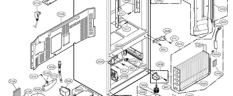
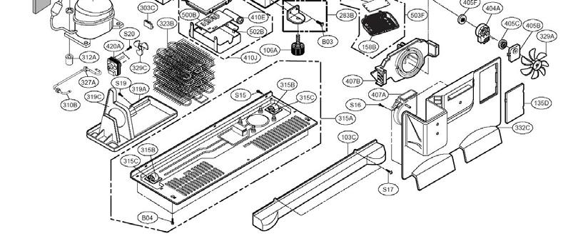
200 Exploded Views LFX25980ST Refrigerator 200 T-71~78
201 Parts List Loc #Part No Description 103A 3650JA2061W Handle, Rear (right, facing it) 103B 3650JA2061X Handle, Rear (left, facing it) 103C 3550JJ0008L Grille, Lower (Kick plate) 105A 5251JA3003B Tube Assembly, Drain 106A 4779JJ2001B Leg Assembly, Adjust 120A ADJ Duct Assembly, Multi 120B ADJ Duct, Multi (no aux. parts) 131A 5074JA2004A Bucket, Ice 135D 3551JJ2028A Cover Assembly, Grille Fan LFX25980ST Refrigerator 201 T-79~85
202 Supplementary Materials LFX25980ST Refrigerator 202 T-86
203 Ohm s Law / Watts Law P = WATTS Watts = Volts 2 x Ohms Watts = Amperes 2 x Ohms Watts = Volts x Amperes I 2 R EI E/R P/E I = AMPERES Amperes = Volts / Ohms Amperes = Watts / Volts Amperes = E = VOLTS Volts = Volts = Watts / Amperes Volts = Amperes x Ohms LFX25980ST Refrigerator 2 E/R PR P/I P WATTS VOLTS IR 203 I CURRENT OHMS E R E/I P/R P/I 2 2 E/P R = OHMS Ohms = Volts / Amperes Ohms = Volts 2 / Amperes Ohms = Watts / Amperes 2 T-86
204 Temperature Conversion ( F vs. C) FORMULAE F = (9/5) C + 32 C = (5/9) x ( F 32) LFX25980ST Refrigerator 204 T-87


205 Service Bulletins LFX25980ST Refrigerator 205 T-87~90
206 Serial Number T-6 LFX25980ST Refrigerator 206
207 Serial Number T-6 LFX25980ST Refrigerator 207

208 LFX25980ST Refrigerator 208
Installation. Leveling
 Your refrigerator was packed carefully for shipment. Remove and discard shelf packaging and tape. Do not remove the serial plate. Location Do not install refrigerator near oven, radiator or other heat
Please read the following installation instructions first after purchasing this product or transporting it to another location.
 9 Installation Overview Please read the following installation instructions first after purchasing this product or transporting it to another location. 1 Unpacking your refrigerator 2 Choosing the proper
REFRIGERATOR SERVICE MANUAL
 REFRIGERATOR SERVICE MANUAL CAUTION BEFORE SERVICING THE PRODUCT, READ THE SAFETY PRECAUTIONS IN THIS MANUAL. MODELS: GR-F218 GR-F258 COLORS: WESTERN BLACK(SB) TITANIUM(TT) SUPER WHITE(SW) STAINLESS(ST)
Refrigerator. Installation Guide. Free Standing Appliance
 Refrigerator Guide Free Standing Appliance Untitled-3 1 2018-04-10 12:31:22 Follow these instructions carefully to prevent accidents and to ensure the proper installation of this refrigerator. WARNING
REFRIGERATOR SERVICE MANUAL
 REFRIGERATOR SERVICE MANUAL CAUTION BEFORE SERVICING THE UNIT, READ THE SAFETY PRECAUTIONS IN THIS MANUAL. MODEL: LFX25960ST LFX25960SW LFX25960SB LFX25960TT LFX21960ST LFX21960SW LFX21960SB LFX21960TT
REFRIGERATOR SERVICE MANUAL
 REFRIGERATOR SERVICE MANUAL CAUTION BEFORE SERVICING THE UNIT, READ THE SAFETY PRECAUTIONS IN THIS MANUAL. MODEL: LRFD25850ST LRFD21855ST COLOR:STAINLESS STEEL CONTENTS SAFETY PRECAUTIONS... 2 1. SPECIFICATIONS...
3. OPERATING INSTRUCTIONS & INSTALLATION
 3-1) Digital Panel 20 3-2) Temperature Control Function 20 3-3) Power Freeze and Power Cool Functions 21 3-4) Child Lock Function 21 3-5) Ice & Water Dispenser Function 22 3-6) C-Fan Motor Delay Function
INSTALLATION. Glass Panel Doors (select models) CAUTION
 CAUTION") Location Do not install refrigerator near oven, radiator or other heat source. If not possible, shield refrigerator with cabinet material. Do not install where temperature falls below 55 F (13 C) or rises
Location Do not install refrigerator near oven, radiator or other heat source. If not possible, shield refrigerator with cabinet material. Do not install where temperature falls below 55 F (13 C) or rises
Korean Side-by-Side Refrigerator Use and Care Manual
 Korean Side-by-Side Refrigerator Use and Care Manual Part No. 10488010 Printed in U.S.A 1996 Raytheon Appliances Amana, Iowa 52203 Contents Electrical Requirements... 2 Model Identification... 2 Model
Viking Installation Guide
 Viking Installation Guide Viking Range Corporation 111 Front Street Greenwood, Mississippi 38930 USA (66) 455-100 For product information, call 1-888-VIKING1 (845-4641) or visit the Viking Web site at
Installation Instructions
 Installation Instructions For Fully Integrated NoFrost Combined Refrigerator-Freezers HCB 1560/1561 7084 429-00 Important Please read and follow these instructions These instructions contain Danger, Warning
Outdoor Beverage Center
 ON/OFF SET TEMPERATURE Outdoor Beverage Center Use and Care Guide Be sure unit is standing upright 24 hours prior to plug-in. Model: BBQ10715 IMPORTANT SAFEGUARDS Read all instructions before using this
STRUCTURE ILLUSTRATION...3 IMPORTANT SAFETY INSTRUCTIONS 4 INSTALLATION INSTRUCTION..4 OPERATING YOUR REFRIGERATOR...5-6
 TABLE OF CONTENTS STRUCTURE ILLUSTRATION....3 IMPORTANT SAFETY INSTRUCTIONS 4 INSTALLATION INSTRUCTION..4 OPERATING YOUR REFRIGERATOR...5-6 FREEZER COMPARTMENT OPERATION 6 CARE & MAINTENANCE..7 CHANGING
DISHWASHER INSTALLATION GUIDE SPECIFICATIONS, INSTALLATION, AND MORE
 DISHWASHER INSTALLATION GUIDE SPECIFICATIONS, INSTALLATION, AND MORE COVE DISHWASHER Contents 3 Cove Dishwasher 4 Specifications 7 Door Panel 9 Installation 15 Troubleshooting Features and specifications
Installation Instructions
 Installation Instructions For Fully Integrated NoFrost Combined Refrigerator-Freezers HCB 1560/1561 HC 1550 7084 327-00 Important Please Read and Follow these Instructions These instructions contain Danger,
Installation Instructions
 Installation Instructions For Fully Integrated NoFrost Combined Refrigerator-Freezers HC 2062 HCB 2062 HC/HCB 2062 7084 445-00 Important Please read and follow these instructions These instructions contain
2008 DOUBLE DRAWER UNDER COUNTER REFRIGERATOR / FREEZER PRODUCTS
 TECHNICAL EDUCATION R-107 2008 DOUBLE DRAWER UNDER COUNTER REFRIGERATOR / FREEZER PRODUCTS KDDC24RVS KDDO24RVX KDDC24CVS KDDO24CVX KDDC24FVS KDDO24FVX JUD248RCRS JUD248RCCX JUD248CCRS JUD248CCCR JUD248FCRS
Installation Instructions
 Installation Instructions For Fully Integrated NoFrost Combined Refrigerator-Freezers HC 2060/2061 HCB 2060/2061 7084 349-00 Important Please Read and Follow these Instructions These instructions contain
Installation Instructions
 Installation Instructions For Fully Integrated NoFrost Combined Refrigerator-Freezers HC 2062 HCB 2062 HC/HCB 2062 7084 341-00 Important Please Read and Follow these Instructions These instructions contain
OWNER S MANUAL FRENCH DOOR REFRIGERATOR. Please read this owner's manual thoroughly before operating and keep it handy for reference at all times.
 OWNER S MANUAL FRENCH DOOR REFRIGERATOR Please read this owner's manual thoroughly before operating and keep it handy for reference at all times. LMXS30746S www.lg.com 2 TABLE OF CONTENTS TABLE OF CONTENTS
FRENCH DOOR REFRIGERATOR OWNER S MANUAL. Please read this guide thoroughly before operating and keep it handy for reference at all times.
 ENGLISH FRANÇAIS ESPAÑOL OWNER S MANUAL FRENCH DOOR REFRIGERATOR Please read this guide thoroughly before operating and keep it handy for reference at all times. LFC25776** LFC21776** P/No. : MFL63728512
OWNER S MANUAL FRENCH DOOR REFRIGERATOR. Please read this owner's manual thoroughly before operating and keep it handy for reference at all times.
 FRANÇAIS ESPAÑOL OWNER S MANUAL FRENCH DOOR REFRIGERATOR Please read this owner's manual thoroughly before operating and keep it handy for reference at all times. LFX29945ST www.lg.com 2 TABLE OF CONTENTS
UNDERCOUNTER LABORATORY REFRIGERATORS and FREEZERS Installation, Operation and Maintenance Instructions
 UNDERCOUNTER LABORATORY REFRIGERATORS and FREEZERS Installation, Operation and Maintenance Instructions INSPECTION When the equipment is received, all items should be carefully checked against the bill
Installation & Operating Guide
 5-036 HOT WATER TANK Installation & Operating Guide Read all instructions thoroughly. Keep this guide for future reference. Proof of purchase is required for Warranty. Staple receipt or proof of purchase
Upright Freezer 048-GM-48307
 Upright Freezer 048-GM-48307 IMPORTANT SAFETY INSTRUCTIONS WARNING Read all of the instructions before using this appliance. When using this appliance, always exercise basic safety precautions, including
BULL INSTRUCTION MANUAL. Model Number: BC-130 REFRIGERATOR BEFORE USE, PLEASE READ AND FOLLOW ALL SAFETY RULES AND OPERATING INSTRUCTIONS.
 BULL INSTRUCTION MANUAL Model Number: BC-130 REFRIGERATOR BEFORE USE, PLEASE READ AND FOLLOW ALL SAFETY RULES AND OPERATING INSTRUCTIONS. 1 REFRIGERATOR SAFETY Your safety and the safety of others are
FRENCH DOOR REFRIGERATOR OWNER S MANUAL. Please read this owner's manual thoroughly before operating and keep it handy for reference at all times.
 ENGLISH FRANÇAIS ESPAÑOL OWNER S MANUAL FRENCH DOOR REFRIGERATOR Please read this owner's manual thoroughly before operating and keep it handy for reference at all times. LFX28978** LFX25978** P/No.: MFL62184410
OWNER S MANUAL FRENCH DOOR REFRIGERATOR. Please read this owner's manual thoroughly before operating and keep it handy for reference at all times.
 FRANÇAIS ESPAÑOL OWNER S MANUAL FRENCH DOOR REFRIGERATOR Please read this owner's manual thoroughly before operating and keep it handy for reference at all times. LMX30995** www.lg.com 2 TABLE OF CONTENTS
FRENCH DOOR REFRIGERATOR OWNER S MANUAL. Please read this owner's manual thoroughly before operating and keep it handy for reference at all times.
 FRANÇAIS ESPAÑOL OWNER S MANUAL FRENCH DOOR REFRIGERATOR Please read this owner's manual thoroughly before operating and keep it handy for reference at all times. LSMX211ST P/NO : MFL62184514 www.lg.com
INSTRUCTION MANUAL (UNIT APPEARANCE MAY VARY FROM IMAGE) BEFORE USE, PLEASE READ AND FOLLOW ALL SAFETY RULES AND OPERATING INSTRUCTIONS.
 BEFORE USE, PLEASE READ AND FOLLOW ALL SAFETY RULES AND OPERATING INSTRUCTIONS.") INSTRUCTION MANUAL Model Number: FR551 REFRIGERATOR-FREEZER (UNIT APPEARANCE MAY VARY FROM IMAGE) BEFORE USE, PLEASE READ AND FOLLOW ALL SAFETY RULES AND OPERATING INSTRUCTIONS. Igloo has a policy of continuous
INSTRUCTION MANUAL Model Number: FR551 REFRIGERATOR-FREEZER (UNIT APPEARANCE MAY VARY FROM IMAGE) BEFORE USE, PLEASE READ AND FOLLOW ALL SAFETY RULES AND OPERATING INSTRUCTIONS. Igloo has a policy of continuous
GCG-10. Instruction Manual. G-Series Cooler. Manual is for the following models: GCG-10-N33EB G-10-N33EB UPRIGHT COOLER
 G-Series Cooler GCG-10 UPRIGHT COOLER Manual is for the following models: GCG-10-N33EB G-10-N33EB Instruction Manual Manual is for the following models: GCG-10-N33EB G-10-N33EB Instruction Manual GCG-10
FRENCH DOOR REFRIGERATOR OWNER S MANUAL. Please read this owner's manual thoroughly before operating and keep it handy for reference at all times.
 FRANÇAIS ESPAÑOL OWNER S MANUAL FRENCH DOOR REFRIGERATOR Please read this owner's manual thoroughly before operating and keep it handy for reference at all times. www.lg.com 2 TABLE OF CONTENTS TABLE OF
OWNER S MANUAL FRENCH DOOR REFRIGERATOR. Please read this owner's manual thoroughly before operating and keep it handy for reference at all times.
 FRANÇAIS ESPAÑOL OWNER S MANUAL FRENCH DOOR REFRIGERATOR Please read this owner's manual thoroughly before operating and keep it handy for reference at all times. LFX32945** www.lg.com 2 TABLE OF CONTENTS
KitchenAid Food Stream Solutions Classic and Integrated Series
 KitchenAid Food Stream Solutions Classic and Integrated Series KitchenAid Chapter list Installation Range overview Installation General Information Function Compressor Power Control Board Defrosting Heating
FRENCH DOOR REFRIGERATOR OWNER S MANUAL. Please read this owner's manual thoroughly before operating and keep it handy for reference at all times.
 OWNER S MANUAL FRENCH DOOR REFRIGERATOR Please read this owner's manual thoroughly before operating and keep it handy for reference at all times. LFXS32726* www.lg.com 2 TABLE OF CONTENTS TABLE OF CONTENTS
KSSS42QDW05, KSSS42QDX05
 CABINET PARTS 42" BUILT IN REFRIGERATOR 4 97 Litho In U.S.A. (mek) 1 Part No. CABINET PARTS 1 Cabinet (Not A Serviceable Part) 3 2005004 Grommet, Tube Crossover 4 1112023 Roller, Front & Rear (4) 5 Support,
Installation Instructions 36 Inch Refrigerator
 Installation Instructions 36 Inch Refrigerator For Use With Models: EF36BNNF, IF36BNNF, PF36BNNF Francis - Voir Page 9 Part No. 106177 Rev. B/13036906 Refrigerator Safety...1 Proper Disposal of Your Refrigerator...1
OWNER S MANUAL FRENCH DOOR REFRIGERATOR. Please read this owner's manual thoroughly before operating and keep it handy for reference at all times.
 FRANÇAIS ESPAÑOL OWNER S MANUAL FRENCH DOOR REFRIGERATOR Please read this owner's manual thoroughly before operating and keep it handy for reference at all times. LMXS30776* MFL69497012_Rev.00 www.lg.com
Installation and User's Manual for Refrigerator Model SCR33
 Installation and for Refrigerator Model SCR33 Introduction Congratulations on your purchase of a Scotsman refrigeration product. For future reference, keep this guide in a safe, accessible location. If
APARTMENT MAINTENANCE SERIES
 ORPORATION CONSUMER SERVICES TECHNICAL EDUCATION GROUP PRESENTS AM-4 APARTMENT MAINTENANCE SERIES TOP-MOUNT REFRIGERATOR/FREEZERS OLD DESIGN 14 cu. ft. MULLION EVAPORATOR DESIGN 12 cu. ft. NEW DESIGN 14
CABINET PARTS For Model: KSSS48QJX00 (Stainless Steel)
") CABINET PARTS 48" BUILT IN REFRIGERATOR 10 02 Litho In U.S.A. (mek) 1 Part No. 1 LITERATURE PARTS LIT2209249 Use & Care Guide LIT2006651 Energy Label LIT2006748 Service & Wiring Sheet LIT628370 Modular
CABINET PARTS 48" BUILT IN REFRIGERATOR 10 02 Litho In U.S.A. (mek) 1 Part No. 1 LITERATURE PARTS LIT2209249 Use & Care Guide LIT2006651 Energy Label LIT2006748 Service & Wiring Sheet LIT628370 Modular
Icemaker Accessory Kit
 www.geappliances.com UK-KIT-3S Icemaker Accessory Kit Safety Information.......... 2 Operating Instructions How The Icemaker Works.....3 How To Use Your Icemaker....3 Troubleshooting Tips Before You Call
rlrm MOflel S DE-BY-SIDE REFRIGERATOR Always consult the Use & Care Guide for more operating information.
 rlrm MOflel 401.40483800 S DE-BY-SIDE REFRIGERATOR Always consult the Use & Care Guide for more operating information. 86002-2008 085 JR O ice BiN For storage of ice cubes made by the icemaker. Do not
REFRIGERATOR SAFETY. Your safety and the safety of others are very important.
 REFRIGERATOR SAFETY Your safety and the safety of others are very important. We have provided many important safety messages in this manual for your appliance. Always read and obey all safety messages.
Icemaker Accessory Kit
 IM-6D Icemaker Accessory Kit Safety Information... 1 Operating Instructions...2 Before You Call For Service...3-5 Normal Sounds You May Hear...2 Preparing for Vacation...2 When You Should Set the Icemaker
G-7s. Instruction Manual. G-Series Cooler COUNTERTOP COOLER. Part No.11IPA
 G-Series Cooler COUNTERTOP COOLER Part No.11IPA-061000 Instruction Manual FOR YOUR FUTURE REFERENCE This easy-to-use manual will guide you in getting the best use of your cooler. Remember to record the
RCM-77. Instruction Manual. G-Series Cooler. U.S. Patent No. 8,215,125 RECHARGE COLD MERCHANDISER
 G-Series Cooler RECHARGE COLD MERCHANDISER U.S. Patent No. 8,215,125 Instruction Manual FOR YOUR FUTURE REFERENCE This easy-to-use manual will guide you in getting the best use of your cooler. Remember
OWNER S MANUAL FRENCH DOOR REFRIGERATOR. Please read this owner's manual thoroughly before operating and keep it handy for reference at all times.
 FRANÇAIS ESPAÑOL OWNER S MANUAL FRENCH DOOR REFRIGERATOR Please read this owner's manual thoroughly before operating and keep it handy for reference at all times. LMXS30776* www.lg.com 2 TABLE OF CONTENTS
Installation Instructions
 Installation Instructions For NoFrost Combined Refrigerator-Freezers with IceMaker CS/CBS 20 7084 337-00 Important Please Read and Follow these Instructions These instructions contain Danger, Warning and
Before Putting Into Use. Important. Tips for Energy Savings
 Before Putting Into Use Before connecting the appliance to the power supply, let it stand for about 2 hours, which will reduce a possibility of malfunctions in the cooling system due to transport handling.
FRENCH DOOR REFRIGERATOR OWNER S MANUAL. Please read this owner's manual thoroughly before operating and keep it handy for reference at all times.
 ENGLISH FRANÇAIS ESPAÑOL OWNER S MANUAL FRENCH DOOR REFRIGERATOR Please read this owner's manual thoroughly before operating and keep it handy for reference at all times. LMX28988** P/No.: MFL62184506
IMPORTANT SAFETY INSTRUCTIONS
 SAFETY INSTRUCTIONS Definitions WARNING Please read all instructions before using this refrigerator. For your Safety DO NOT store or use gasoline, or other flammable liquids in the vicinity of this or
Installation Instructions
 Installation Instructions For Fully Integrated NoFrost Combined Refrigerator-Freezers HC 2062 HCB 2062 HC/HCB 20 7082 373-00 Important PLEASE READ AND FOLLOW THESE INSTRUCTIONS These instructions contain
REFRIGERATOR SERVICE MANUAL CAUTION BEFORE SERVICING THE UNIT, READ THE SAFETY PRECAUTIONS IN THIS MANUAL.
 REFRIGERATOR SERVICE MANUAL CAUTION BEFORE SERVICING THE UNIT, READ THE SAFETY PRECAUTIONS IN THIS MANUAL. MODELS: LFX23961SW /01 LFX23961ST /01 LFX23961SB /01 CONTENTS SAFETY PRECAUTIONS... 1. SPECIFICATIONS...
ICE MAKER Use & Care Guide. Table of Contents... 2
 ICE MAKER Use & Care Guide Table of Contents... 2 2217247 ICE MAKER SAFETY...2 ICE MAKER INSTALLATION...3 Unpacking...3 Location Requirements...3 Electrical Requirements...3 Leveling...4 Water Supply Connection...4
FRENCH DOOR REFRIGERATOR OWNER S MANUAL. Please read this owner's manual thoroughly before operating and keep it handy for reference at all times.
 FRANÇAIS ESPAÑOL OWNER S MANUAL FRENCH DOOR REFRIGERATOR Please read this owner's manual thoroughly before operating and keep it handy for reference at all times. www.lg.com 2 TABLE OF CONTENTS TABLE OF
9.9 CU.FT. TOP MOUNT REFRIGERATOR INSTRUCTION MANUAL. Model No.: HVDR1040W HVDR1040B HVDR1040S
 9.9 CU.FT. TOP MOUNT REFRIGERATOR INSTRUCTION MANUAL Model No.: HVDR1040W HVDR1040B HVDR1040S To ensure proper use of this appliance and your safety, please read the following instructions completely before
GE Monogram. Installation. Instructions. Stainless Steel Bottom Mount Built-In Refrigerators. Models ZICS36N RH ZICS36N LH
 GE Monogram Installation Instructions Stainless Steel Bottom Mount Built-In Refrigerators Models ZICS36N RH ZICS36N LH Before you begin - Read these instructions completely and carefully. IMPORTANT - Save
Owner s Manual 33-bottle Under-Counter Wine Cooler Model: WC-3302US
 Owner s Manual 33-bottle Under-Counter Wine Cooler Model: WC-3302US Please read this manual carefully before use and keep in a safe place for future reference. IMPORTANT SAFETY INSTRUCTIONS WARNING To
INSTALLATION INSTRUCTIONS
 INSTALLATION INSTRUCTIONS BUILT-IN BOTTOM MOUNT REFRIGERATOR/FREEZER DBRTGK72SS-GRILLE KIT (FOR designer SERIES ONLY) VIKING RANGE CORPORATION 111 Front Street Greenwood, Mississippi (MS) 38930 USA (662)
USE AND CARE GUIDE GUIDE D UTILISATION ET D ENTRETIEN GUIA DE USO Y CUIDADO
 EN FRENCH DOOR BOTTOM FREEZER/REFRIGERATOR FR RÉFRIGÉRATEUR À PORTES FRANÇAISES/CONGÉLATEUR EN BAS ES REFRIGERADOR CON CONGELA- DOR INFERIOR DE PUERTA DOBLE USE AND CARE GUIDE GUIDE D UTILISATION ET D
Front Roller (2) Screw Roller (Rear) (2) Screw Clip, Grille Screw Insert, Air
 Screw Roller (Rear) (2) Screw Clip, Grille Screw Insert, Air") 2 2174748 Front Roller (2) 3 489456 Screw 4 981122 Roller (Rear) (2) 5 489427 Screw 6 2155013 Clip, Grille 7 489242 Screw 8 2176796 Insert, Air Baffle 9 2156056 Shim 10 2158579 Enclosure, Terminal Block
2 2174748 Front Roller (2) 3 489456 Screw 4 981122 Roller (Rear) (2) 5 489427 Screw 6 2155013 Clip, Grille 7 489242 Screw 8 2176796 Insert, Air Baffle 9 2156056 Shim 10 2158579 Enclosure, Terminal Block
Norcold Repair Guide for Ice Maker
 Norcold Repair Guide for Ice Maker Section 10 Table of Contents Page: 10-2 General Description 10-2 Refrigerator Specifications 10-2 Refrigerator Operating Limits 10-2 Refrigerator Current Draws 10-2 Ice
UNDERCOUNTER REFRIGERATORS AND FREEZERS Installation, Operation and Maintenance Instructions
 UNDERCOUNTER REFRIGERATORS AND FREEZERS Installation, Operation and Maintenance Instructions Please read this manual completely prior to installing and operating this equipment. This manual describes how
RCM-77. Instruction Manual. G-Series Cooler. Manual is for the following model: RCM-77-N23EB. U.S. Patent No. 8,215,125 RECHARGEABLE COLD MERCHANDISER
 G-Series Cooler RCM-77 RECHARGEABLE COLD MERCHANDISER Manual is for the following model: RCM-77-N23EB U.S. Patent No. 8,215,125 Instruction Manual Manual is for the following model: RCM-77-N23EB Instruction
DOUBLE DOOR COMPACT REFRIGERATOR. User Manual MODEL:KSTRC312BW KSTRC312BB
 DOUBLE DOOR COMPACT REFRIGERATOR User Manual MODEL:KSTRC312BW KSTRC312BB SERIAL/MODEL # S - IMPORTANT SAFETY INSTRUCTIONS Read and Save These Instructions This Owner s Guide provides specific operating
7ED27DQXDN01 GABINETE
 7ED27DQXDN01 GABINETE 7ED27DQXDN01 GABINETE 2 4386774 FRONT ROLLER (2) 3 489456 SCREW (S/P) 4 981122 ROLLER (REAR) (2) 5 489427 SCREW (S/P) 6 2155013 CLIP, GRILLE (S/P) 7 489478 SCREW (S/P) 9 2181911 SHIM
Glass Door Refrigerators
 To better help you obtain assistance or service should you ever need it, write down the following information about the product. This information is on the identification label located on the left hand
 Installation Guide BI-98 Ice Maker www.u-lineservice.com Phone (414) 354-0300 FAX (414) 354-7905 Service & Parts Tech Lines Phone (800) 779-2547 FAX (414) 354-5696 OnlineService@U-Line.com 2005 U-Line
Hazards or unsafe practices that may result in severe personal injury or death.
 quick start guide English RF26HF** 1. Safety Information Safety information Before using your new Samsung French Door Refrigerator, please read this manual thoroughly to ensure that you know how to operate
CABINET PARTS For Models: 7GS2SHEXPQ03, 7GS2SHEXPL03 (White) (Stainless VCM) REFRIGERATOR
 (Stainless VCM) REFRIGERATOR") CABINET PARTS REFRIGERATOR 03 07 Litho In U.S.A. (mat) 1 Part No. Rev A CABINET PARTS 1 Literature Parts 2261383 Use & Care Guide 2255955 Service & Wiring Sheet 2261377 Energy Guide 2220407 Modular Icemaker
CABINET PARTS REFRIGERATOR 03 07 Litho In U.S.A. (mat) 1 Part No. Rev A CABINET PARTS 1 Literature Parts 2261383 Use & Care Guide 2255955 Service & Wiring Sheet 2261377 Energy Guide 2220407 Modular Icemaker
LMX25981**, LMX21981**
 To contact LG Electronics, 24 hours a day, 7 days a week: 1-800-243-0000 Or visit us on the Web at: us.lge.com Pour contacter LG Electronics, 24 heures par jour, 7 jours par semaine: 1-800-243-0000 Ou
Viking Installation Guide
 Viking Installation Guide Viking Range Corporation 111 Front Street Greenwood, Mississippi 38930 USA (662) 455-1200 For product information, call 1-888-VIKING1 (845-4641) or visit the Viking Web site at
G-10f/GCG-10f UPRIGHT COOLER
 G-Series Cooler G-10f/GCG-10f UPRIGHT COOLER Manual is for the following models: G-10F, G-10-F33EB GCG-10F, GCG-10-F33EB GCG-10F2, GCG-10-F233EB G-10-F33EB-HC, GCG-10-F33EB-HC GCG-10-F233EB-HC Instruction
REFRIGERATOR SERVICE MANUAL CAUTION BEFORE SERVICING THE UNIT, READ THE SAFETY PRECAUTIONS IN THIS MANUAL.
 REFRIGERATOR SERVICE MANUAL CAUTION BEFORE SERVICING THE UNIT, READ THE SAFETY PRECAUTIONS IN THIS MANUAL. Model #s: 795.78733.806 795.78739.806 P/. MFL55142408 (Last Revision: January. 18 2010) CONTENTS
PR-L2466W- PA. Operating Instructions. High Performance Refrigerator PR-L2466W-PA
 Operating Instructions High Performance Refrigerator PR-L2466W- PA PR-L2466W-PA Please read these instructions carefully before using this product, and save this manual for future use. See page 11 for
INSTALLATION and OPERATION INSTRUCTIONS
 INSTALLATION and OPERATION INSTRUCTIONS SINGLE DOOR freezer MODEL NOS. FN FS Finished Stainless Steel Top Non-Finished Top FS FN IMPORTANT INFORMATION This manual has been prepared to assist you in the
Use & Care. All about the. of your Refrigerator TABLE OF CONTENTS. Automatic Ice Maker - Freezer Important Safety Instructions...
 All about the Use & Care of your Refrigerator TABLE OF CONTENTS Important Safety Instructions...2 Features at a Glance...4 Installation...5 Door Removal Instructions...8 Automatic Ice Maker - Freezer...24
CABINET PARTS For Models: ASD2522WRS07 (Stainless)
") CABINET PARTS REFRIGERATOR 9 11 Litho In U.S.A. (wam) (psw) 1 Part No. Rev. A CABINET PARTS 1 Literature Parts W10321484 Use & Care Guide W10275776 Service & Wiring Sheet W10234042 Energy Guide 628370
CABINET PARTS REFRIGERATOR 9 11 Litho In U.S.A. (wam) (psw) 1 Part No. Rev. A CABINET PARTS 1 Literature Parts W10321484 Use & Care Guide W10275776 Service & Wiring Sheet W10234042 Energy Guide 628370
Installation Instructions
 Installation Instructions For NoFrost Combined Refrigerator-Freezers with IceMaker CS 2060, CS 2061 7084 339-00 Important Please Read and Follow these Instructions These instructions contain Danger, Warning
BUILT-IN DISHWASHER INSTALLATION INSTRUCTIONS
 BUILT-IN DISHWASHER INSTALLATION INSTRUCTIONS PLEASE READ COMPLETE INSTRUCTIONS BEFORE YOU BEGIN LEAVE INSTALLATION INSTRUCTIONS AND USER'S GUIDE WITH OWNER ALL ELECTRIC WIRING AND PLUMBING MUST BE DONE
GENERAL LABORATORY REFRIGERATORS AND FREEZERS Installation, Operation and Maintenance Instructions
 GENERAL LABORATORY REFRIGERATORS AND FREEZERS Installation, Operation and Maintenance Instructions INSPECTION When the equipment is received, all items should be carefully checked against the bill of lading
FRENCH DOOR REFRIGERATOR
 OWNER'S MANUAL ENGLISH FRANÇAIS ESPAÑOL FRENCH DOOR REFRIGERATOR Read this owner's manual thoroughly before operating the appliance and keep it handy for reference at all times. LSFXC2476* LSFXC2496* LSFD2491**
G-10s. Instruction Manual. G-Series Cooler UPRIGHT COOLER. Part No.11IPA
 G-Series Cooler UPRIGHT COOLER Part No.11IPA-062800 Instruction Manual FOR YOUR FUTURE REFERENCE Thank you for using our product. This manual will guide you in getting the best use of your cooler. Remember
GCG-9. Instruction Manual. G-Series Cooler. Manual is for the following models: GCG-9-N13EB G-9-N13EB GCG-9-B13EB UPRIGHT COOLER
 G-Series Cooler UPRIGHT COOLER Manual is for the following models: -N13EB G-9-N13EB -B13EB Instruction Manual FOR YOUR FUTURE REFERENCE This easy-to-use manual will guide you in getting the best use of
UNDERCOUNTER LABORATORY FRONT BREATHING REFRIGERATORS AND FREEZERS Installation, Operation and Maintenance Instructions
 UNDERCOUNTER LABORATORY FRONT BREATHING REFRIGERATORS AND FREEZERS Installation, Operation and Maintenance Instructions Please read this manual completely prior to installing and operating this equipment.
WHIRLPOOL REFRIGERADOR KSRS25FGSS13
 CABINET, LITERATURE 1 CABINET, LITERATURE 1 LIT2206106 Literature Parts (Use & Care Guide) 2 2174748 Front Roller (2) 3 3400517 Screw 4 2196236 Roller (Rear) (2) 5 489427 Screw 6 2155013 Clip, Grille 7
Compact Refrigerator. User Manual Model 3590A
 By Compact Refrigerator User Manual Model 3590A DANGER Risk of child entrapment. Before you throw away your old refrigerator or freezer, take off the doors. Leave the shelves in place so that children
INSTALLATION INSTRUCTIONS
 Proper isposal of Your Old Refrigerator efore You Throw way Your Old Refrigerator or Freezer: Take off the doors. Leave the shelves in place so that children may not easily climb inside. Suffocation Hazard
LFX25980**, LFX21980**
 To contact LG Electronics, 24 hours a day, 7 days a week: 1-800-243-0000 Or visit us on the Web at: us.lge.com Pour contacter LG Electronics, 24 heures par jour, 7 jours par semaine: 1-800-243-0000 Ou
CABINET PARTS. For Models: GD2SHAXNQ00, GD2SHAXNT00, GD2SHAXNB00, GD2SHAXNS00, GD2SHAXNL00 (White) (Biscuit) (Black) (Stainless Steel) (Stainless VCM)
 (Biscuit) (Black) (Stainless Steel) (Stainless VCM)") CABINET PARTS REFRIGERATOR 5 04 Litho In U.S.A. (kdj) 1 Part No. Rev. A CABINET PARTS 1 Literature Parts 2261717 Use & Care Guide 2255955 Service & Wiring Sheet 2305881 Energy Guide 2220407 Modular Icemaker
CABINET PARTS REFRIGERATOR 5 04 Litho In U.S.A. (kdj) 1 Part No. Rev. A CABINET PARTS 1 Literature Parts 2261717 Use & Care Guide 2255955 Service & Wiring Sheet 2305881 Energy Guide 2220407 Modular Icemaker
CABINET PARTS For Model: KSSC42QTS02 (Stainless Steel)
") CABINET PARTS 42" BUILT IN REFRIGERATOR 10 11 Litho In U.S.A. (jdc)(psw) 1 Part No. Rev. A 1 Literature Parts W10161714 Use & Care Guide W10164072 Energy Guide W10159832 Service & Wiring Sheet 2306424
CABINET PARTS 42" BUILT IN REFRIGERATOR 10 11 Litho In U.S.A. (jdc)(psw) 1 Part No. Rev. A 1 Literature Parts W10161714 Use & Care Guide W10164072 Energy Guide W10159832 Service & Wiring Sheet 2306424
CABINET PARTS REFRIGERATOR
 CABINET PARTS REFRIGERATOR 1 94 Litho In U.S.A. 1 Part No. CABINET PARTS 2 2152011 Front Roller (2) 3 489393 Screw, 4 981122 Roller (Rear) (2) 5 488454 Screw 6 2155013 Clip, Grille 7 489242 Screw 9 836196
Model Number Nomemclature... 1 Specifications... 3 Refrigeration System... 4 Freezer and Refrigerator Air Circulation... 5 Display Designs...
 Samsung AD Refrigerator Familiarization Maytag Technical Training Services 2004 ABS-L2004-012 Model Number Nomemclature... 1 Specifications... 3 Refrigeration System... 4 Freezer and Refrigerator Air
INSTALLATION INSTRUCTIONS
 Proper Disposal of Your Old Refrigerator WRNING Suffocation Hazard Remove doors from your old refrigerator. Failure to do so can result in death or brain damage. IMPORTNT: hild entrapment and suffocation
Use & Care. All about the. of your Refrigerator TABLE OF CONTENTS. Important Safety Instructions...2. Storage Features Features at a Glance...
 All about the Use & Care of your Refrigerator TABLE OF CONTENTS Important Safety Instructions...2 Features at a Glance...4 Installation...5 Door Removal Instructions - Style 1...7 Storage Features...17
FRENCH DOOR REFRIGERATOR OWNER S MANUAL. Please read this owner's manual thoroughly before operating and keep it handy for reference at all times.
 OWNER S MANUAL FRENCH DOOR REFRIGERATOR Please read this owner's manual thoroughly before operating and keep it handy for reference at all times. LFXS29766* www.lg.com 2 TABLE OF CONTENTS TABLE OF CONTENTS
Use & Care. All about the. of your Refrigerator TABLE OF CONTENTS. Automatic Ice Maker - Freezer Important Safety Instructions...
 All about the Use & Care of your Refrigerator TABLE OF CONTENTS Important Safety Instructions...2 Features at a Glance...4 Installation...5 Door Removal Instructions...9 Automatic Ice Maker - Freezer...26
Installation Instructions
 Instructions For Fully Integrated NoFrost Combined Refrigerator-Freezers HC 1540/1541 7084 433-00 Important Please read and follow these instructions These instructions contain Danger, Warning and Caution
Installation Instructions
 Installation Instructions For Free Standing NoFrost Combined Refrigerator-Freezers CS 1660 7084 203-00 Important Please Read and Follow these Instructions These instructions contain Danger, Warning and