ULSA 025, 035, 050, 075, 100
|
|
|
- Giles Heath
- 5 years ago
- Views:
Transcription
1 1407ULSA EN Condensing low emission gas fired air heater ULSA 025, 035, 050, 075, 100 This appliance meets the following EC Directives DIR 2009/142/EC : GAD DIR 2004/108/EC : EMC DIR 2006/95/EC : LVD DIR 2006/42/EC : MD ULSA 050 INSTALLATION COMMISSIONING SERVICING USER INSTRUCTIONS Applies to : Belarus, Bulgaria, China, Czech Republic, Croatia, Cyprus, Denmark, Estonia, Finland, Greece, Hungary, Iceland, Latvia, Lithuania, Montenegro, New Zealand, Norway, Poland, Portugal, Romania, Russian Federation, Serbia, Slovakia, Slovenia, South Africa, Spain, Sweden, Turkey, Ukraine Please read this document carefully before commencing the installation and leave it with the user or attached to the appliance or gas service meter after installation! ATTENTION The manufacturer does not take any responsibility in the event of non observance of the regulation concerning the connection of the apparatus causing a harmful operation possibly resulting in damage to the apparatus and/or environment in which the unit is installed. Reznor Menen J&M Sabbestraat 130/A Menen Belgium Subject to modifications 1407ULSA--EN, p. 1/33
2 TABLE OF CONTENTS 1 Hazard intensity levels 2 General Warnings General Warranty Uncrating & preparation Heater location 3 Technical data 4 Dimensions & clearances 5 Internal lay out 6 Installing 7 Air supply & flue systems 8 Condensation drain pipe connection 9 Gas connection/gas supply 10 Electrical connections 11 Commissioning, lighting & operation 12 Maintenance 13 Fault finding 14 Spare parts list 15 User instructions 16 Declaration of conformity 1. HAZARD INTENSITY LEVELS DANGER Failure to comply will result in severe personal injury or death and/or property damage. WARNING Failure to comply could result in severe personal injury or death and/or property damage. CAUTION Failure to comply could result in minor personal injury and/or property damage. 1407ULSA--EN, p. 2/33
3 2. GENERAL 2.1 WARNINGS WARNINGS For your safety, if you smell gas : Do not try to light any appliance Do not touch any electrical switch, do not use any phone in your building Evacuate all personnel Contact your gas supplier immediately Do not store or use petrol or other flammable vapours and liquids in the vicinity of the appliance. Improper installation, adjustment, alteration, service or maintenance can cause property damage, injury or death. Read the installation, operation and maintenance instructions thoroughly before installing or servicing this equipment. Do not use this appliance if any part has been immersed in water. Immediately call a qualified service technician to inspect the appliance and replace any gas control that has been immersed in water. This appliance is not intended for use by persons (including children) with reduced sensory or mental capacities or lack of experience and knowledge unless they have been given supervision or instructions concerning use of the appliance by a person responsible for their safety. Children should be supervised to ensure that they do not play with the appliance. Should overheating occur or the gas supply fails to shut off, shut off the manual gas valve to the appliance before shutting off the electrical supply. Gas fired appliances are not designed for use in hazardous atmospheres containing flammable vapours or combustible dust, in atmospheres containing chlorinated or halogenated hydrocarbons or in appliances with airborne silicone substances. The manual should be kept in a safe place for future reference. Unauthorised modification of this appliance or departure from use in the manner, for which it was intended by the manufacturer or installed in a manner contrary to these instructions, may constitute a hazard and jeopardize all warranties. Deviations should only be carried out after formal consent has been obtained from the manufacturer. Use only factory authorized parts when replacement is required. In case of persisting problems, contact your distributor 1407ULSA--EN, p. 3/33
4 2.2 GENERAL The instructions in this manual apply to the condensing gas fired air heater model ULSA. All models and sizes are available for use with either natural, propane or butane gas within operating temperatures between 15 C and 40 C. These heaters are designed for use in domestic, industrial and commercial premises, suitable only for indoor installation The type of gas, the input rate and the electrical supply requirements are shown on the heater rating plate. The instructions are only valid for the country of use indicated on the appliance. If not correct contact your supplier. Installation should be done by a suitably qualified installer in accordance with these instructions and with all rules in force. The installation manual is shipped with the heater. Verify that the literature is correct for the heater being installed. If the manual is incorrect for the heater, contact the supplier before beginning installation. Ensure the environment in which the air heater will be installed will not create a hazard i.e. where excessive dust, flammable or corrosive substances and/or vapours and combustible materials may be present. 2.3 WARRANTY Warranty is void if : Heaters are used in atmospheres containing flammable vapours or atmospheres containing chlorinated or halogenated hydrocarbons or any contaminant (silicone, aluminium oxide, etc...). The installation is not in accordance with these instructions. Wiring is not in accordance with the diagram furnished with the heater. Unit is installed without proper clearance to combustible materials or without proper ventilation and air for combustion. Air throughput is not adjusted within the range specified on the rating plate. 2.4 UNCRATING & PREPARATION The unit was test operated and inspected at the factory prior to crating and was in proper operating condition. If the heater has incurred damage in shipment, document the damage with the transport company and contact your supplier. Before installation check that the appliance as described on the packaging label is in accordance with the correct type and model as specified on the data plate and complies with your customer order. After unpacking the appliance, leave it fastened to any base packing for transportation until it has been suspended or until just before base mounting. This affords protection to the underside. Check the rating plate to determine if the heater is appropriate for the intended installation. Read the manual thoroughly and become familiar with the installation requirements of your heater. If you do not have knowledge of local requirements, check with the gas supplier and any other local agencies that might have requirements concerning this installation. Before beginning make preparations for necessary supplies, tools and manpower. If the installation includes optional parts, install these options before the heater is suspended. Follow the instructions included in the option package. 1407ULSA--EN, p. 4/33
5 2.5 HEATER LOCATION Attention Flue requirements may affect location. Consult section 7 before making a final determination. Use the minimum clearances as illustrated in figure 2 and the throw data mentioned in table 1 (Technical Data) to define where to locate the heater. Also respect the recommended minimum height as given in table 1. For best results, the heater should be placed with certain rules in mind. Always ensure that minimum clearances are maintained. Locating a unit heater above the maximum recommended height can result in significant air stratification. When possible, heaters should be arranged to blow toward or along exposed wall surfaces. Suspended heaters are most effective when located as close to the working zone as possible, but care should be exercised to avoid directing the discharged air directly on to the room occupants. Partitions, columns, counters or other obstructions should be taken into consideration when locating the unit heater so that a minimum quantity of airflow will be deflected by such obstacles. When units are located in the centre of the space to be heated, the air should be discharged toward the exposed walls. In large areas, units should be located to discharge air along exposed walls with extra units provided to discharge air towards the centre of the area. For optimum results heaters are best used in conjunction with recirculating air fans suspended at high level. At those points where infiltration of cold air is excessive, such as entrance doors... it is desirable to locate the unit so that it will discharge directly towards the source of cold air, typically from a distance of 4.5m to 6m or install a downflown unit over the door opening. WARNING If touched, the vent pipe and internal heater surfaces that are accessible from outside the heater will cause burns. Suspend the heater so that these components cannot be touched! CAUTION Do not locate the heater where it may be exposed to water. Attention Hazards of chlorine apply to the location of the combustion air inlet The presence of chlorine vapours in the combustion air of gas fired heating equipment presents a potential corrosion hazard Care should be taken to separate these vapours from the combustion process. This may be done by wise location of the unit flue and combustion air terminals with regard to exhausters or prevailing wind directions. Chlorine is heavier than air. Keep this fact in mind when determining installation location of the heater in relation to building exhaust systems. Where chlorine vapours are prevalent, heaters with special grade 316 AISI stainless steel heat exchangers are recommended. 1407ULSA--EN, p. 5/33
6 Table 1a 3. TECHNICAL DATA ULSA Gas category Cat. See table 1b Comb. air & flue, type B instal (1) Comb. air & flue, type c instal (1) B22p C12, C32, C42, C52, C62, C82 Maximum heat input (Hs) kw 28,30 37,00 56,00 78,40 106,30 Maximum heat input (Hi) kw 25,50 33,30 50,40 70,60 95,70 Minimum heat input (Hs) kw 5,70 7,20 11,40 15,90 20,90 Minimum heat input (Hi) kw 5,20 6,50 10,30 14,30 18,90 Maximum heat output kw 25,00 32,70 49,70 69,60 94,40 Minimum heat output kw 5,60 7,10 11,20 15,20 20,50 Max thermal efficiency at max heat input (G20) % 98,30 98,00 98,60 98,60 98,60 Max thermal efficiency at min heat input (G20) % 109,20 108,80 108,70 106,50 108,90 CO 2 gas at max heat input Nat gas G20 (H) vol % 8,43 8,42 8,44 8,42 8,42 Prop G31 vol % 9,81 9,81 9,81 9,80 9,80 Propane restrictor diameter mm 3, Gas consumption at maximum heat input Gas consumption at minimum heat input Inlet pressures Nat gas G20 (H) Nat gas G20 (H) Nat gas G20 (H) m³/h m³/h mbar 2,59 0,55 See table 1b 3,39 0,69 5,07 1,09 7,27 1,52 9,76 2,00 Prop G31 Prop G31 Prop G31 kg/h kg/h mbar 1,99 0,4 See table 1b 2,6 0,51 3,93 0,8 5,51 1,12 7,47 1,47 Air volume (15 C) m³/h Temperature rise at max load K 25,3 25,7 25,9 25,7 26,2 Horizontal throw (4) m Sound pressure level Lp (5) db(a) , Maximum absorbed power kw 0,29 0,32 0,69 0,75 1,25 Gas connection (2) Electrical connection 1/2" G 3/4" G 230/240 V 1N50Hz Connection diameter for flue gas and combustion air mm Condensation connection/outlet Condensate quantity l/h 1, ,5 3,5 Recommended mounting heigth (3) m 3 3,5 3,5 4 4 Weight kg Protection grade IP IP 20 CE Approval number PIN 0461CO1016 (1)Gas Appliance Classifications for Approved Venting Methods based on CEN-report CR1749:2001 (2)Gas connection size is not necessarily the supply line size. There is a difference between the gas connection diameter and the diameter of the supply line. Always use the most adequate dia of the supply line to minimize the pressure drop through the gas pipes if necessary reduce the diameter of the supply line at the inlet of the unit. (3)Height from the floor to bottom surface of heater. These are recommendations only. Positioning of unit heaters for proper performance is application dependent. Operation is affected by other air moving equipment in the space, obstructions to the airflow, draughts and/or close proximity to doors or windows, etc Care should be taken to avoid mounting the heaters above these recommendations, unless downturn nozzle options are used, as significant stratification may occur resulting in poor floor coverage and higher energy losses through the roof structure. (4)Isothermal conditions at 20 C ambient air temperature, discharge louvre zero deflection, v = 0,5 m/s. (5)Sound pressure level in db(a) : measured at 5 meters from the unit with A=160m² & Q=2 Table 1b : Gas category & inlet pressures gas cat inlet pressure gas cat inlet pressure gas cat inlet pressure gas cat inlet pressure country G20 (mm) G31 (mm) country G20 (mm) G31 (mm) Belarus I2H 20 I3P 37 Montenegro I2H 20 I3P 37 Bulgaria I2H 20 I3P 37 New Zeeland I2H 20 I3P 37 China I2H 20 I3P 37 Norway I2H 20 I3B/P 30 Czech Republic I2H 20 I3P 37 Poland I2E 20 I3B/P 30 Croatia I2H 20 I3P 37 Portugal I2H 20 I3P 37 Cyprus I2H 20 I3B/P 30 Romania I2E 20 I3B/P 30 Denmark I2H 20 I3B/P 30 Russian Federation I2H 20 I3P 37 Estonia I2H 20 I3B/P 30 Serbia I2H 20 I3P 37 Finland I2H 20 I3B/P 30 Slovakia I2H 20 I3P 37 Greece I2H 20 I3P 37 Slovenia I2H 20 I3P 37 Hungary I2H 20 I3B/P 50 South Africa I2H 20 I3P 37 Iceland I2H 20 I3P 37 Spain I2H 20 I3P 37 latvia I2H 20 I3P 37 Sweden I2H 20 I3B/P 30 Lithuania I2H 20 I3P 37 Turkey I2H 20 I3P 37 Ukraine I2H 20 I3P ULSA--EN, p. 6/33

 4.")
 5.")
 6.")


7 4. DIMENSIONS & CLEARANCES 4.1 DIMENSIONS ULSA 025, 035, 050 & 075 Figure 1a : 1. Combustion air inlet ( D) 4. Electrical connections 2. Flue connection ( D) 5. Service panel 3. External gas connection (C) 6. Condensate drain ULSA A B C D E F I J K L M /2" G /2" G /4" G /4" G (all dimensions in mm, tolerance 3mm) 1407ULSA--EN, p. 7/33

")


 6.")


8 ULSA 100 Figure 1b : 1. Combustion air inlet ( 100mm) 4. Electrical connections 2. Flue connection ( 100mm) 5. Service panel 3. External gas connection (3/4 G) 6. Condensate drain (all dimensions in mm, tolerance 3mm) 1407ULSA--EN, p. 8/33
 : heaters can be base mounted on suitable non-combustible")

9 4.2 CLEARANCES Figure 2 : ULSA X Y Z(*) U V (*) : heaters can be base mounted on suitable non-combustible supports Figure 3 : 5. INTERNAL LAYOUT 1 Metal mesh burner 2 Zero pressure regulator 3 Venturi 4 Differential pressure switch 5 Burner controller 6 Flue gas extraction fan 7 Inspection window + ignitor+ionisation electrode 1407ULSA--EN, p. 9/33


10 WARNING 6 INSTALLING Check the supporting structure to verify that it has sufficient load carrying capacity to support the unit weight. Suspend the heater only from the threaded nut inserts. Do not suspend from the heater cabinet panels. Do not place or add additional weight to the suspended heater. The location where the air heater is to be installed must provide sufficient space around the heater for servicing and clearances for safety (see figure 2). When the unit is lifted for suspension, leave the unit on the pallet. Before hanging verify that all screws originally used to fix the shipping supports are re screwed into the cabinet. Ensure that the heater is installed in a level plane and vibration free. The air heater must be fastened securely to any base mounting arrangement. The heater is supplied with four point suspension. All points must be used. Threaded nut inserts are provided on each side of the top of the heater. See figure 4. After suspension the air heater should be rigid so as to avoid placing a strain on the flue system, gas services, electrical wiring and duct work. 1 BSP mounting cap nuts are optional. In case of a type C installation, the distance between the floor and the underside of the air heater must be at least 1.70m. Combustion air should be taken from a height that exceeds the above mentioned height of 1.70m. Also thermostats and switches which are not sparkless have to be installed at a minimum height of 1.70m. Figure 4 : Be sure that the threaded hanger rods are locked to the heater as illustrated in this figure. Recommended maximum hanger rod length is 1.8m. Where longer drops are required, ensure that restraints are fitted to prevent excess lateral movement and supports are adequately sized. Alternatively the unit can also e base mounted on a non combustible support. In this case ensure that unit is securely fixed on the base. 1407ULSA--EN, p. 10/33
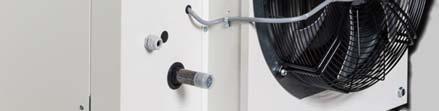
11 7 AIR SUPPLY & FLUE SYSTEM 7.1 GENERAL WARNING The flue must be in accordance with BS6230 or BS5440. Local requirements may apply in addition to national requirements. Failure to provide proper flueing could result in death, serious injury and/or property damage. The products of combustion must be flued to outside atmosphere. Common flues (for more than one appliance) must not be used. Model ULSA heaters may be installed as type B or type C installations. The unit heaters are designed to operate safely and efficiently with either a horizontal or vertical flue system when installed according to the specific requirements and instructions. If this heater is replacing an existing heater, be sure that the flue is of the correct size and that the existing flue is in good condition. A correctly sized flue system is required for safe operation of the heater. An improper sized flue system can cause unsafe conditions and/or create condensation. The units may be installed as a balanced flue type C heater requiring both a combustion air inlet pipe and a flue pipe or as a power vented heater type B where the combustion air is taken from the space where heater is installed and which requires only a flue pipe exhausting to outdoors. All products of combustion must be flued to outdoor atmosphere. Each heater installed as a type B appliance must be fitted with an individual flue pipe and the combustion air inlet opening must be provided with a protection grill. Each heater installed as a type C appliance must be fitted with an individual combustion air/flue pipe system. Type C2 appliance, with single pipe system for supply of combustion air and evacuation of flue gasses, are not allowed. For testing, the flue pipe should include a sealable test point. Ideally the test point should be at least 450mm away from the air heater flue connection socket. However if a concentric flue is attached directly to the connection sockets then the combustion should be tested through the flue outlet collar via a drilled test point which must be securely plugged on completion. Follow the flue pipe manufacturer s installation instructions for making joints, including connections to the air heater, for passing through a building element and for support requirements. Remark : A cover plate can be installed on the rear or top panel. The plate with the fresh air inlet and the flue outlet socket is factory installed on the rear panel but can easily be replaced on the top panel if required. Figure 5 : Combustion air and flue pipe sockets (on top) Combustion air inlet Flue connection 1407ULSA--EN, p. 11/33
12 Attention Condense drain A condensation drain must be fitted to both the unit and the flue outlet to properly drain all condensation. The condensation drain from the flue must be constructed from non corrodible material not less than 20mm diameter. Copper or copper based alloys must not be used for condensation drain. Consult section 8 : Condensation drain pipe connections 7.2 POWER VENTED INSTALLATIONS (type B appliances) WARNING Single wall flue pipe exposed to cold air or run through unheated areas should be insulated to avoid condensation. If the flue passes through a combustible element of the building it must be enclosed by a sleeve of non combustible material and separated from the sleeve by at least a 25mm air break. The temperature of any combustible material near to the flue must not exceed 65 C when the heater is in operation. The flue must be at least 50mm away from any combustible material. Provision must be made for condensation to flow freely to a point to which it can be released, i.e. drain. If the air heater is to be installed as a type B appliance, air for combustion will be taken from within the space where the heater is installed. Ensure that an adequate air supply for combustion and ventilation is provided within the building in accordance with BS6230 or BS5440 plus all other relevant regulations & rules in force. Single wall flue pipe seamless aluminium/stainless steel pipes are required. All joints must be sealed to prevent products of combustion from leaking into the building. Do not install vent piping near any source of heat A protection grill type IP20 which can be ordered at your supplier, must be mounted on the combustion air intake. Table 2 shows the flue pipe sizes and maximum pipe lengths. B22p roof Figure 6 : Approved appliances type B B22p 7.3 BALANCED FLUE INSTALLATION (type C appliances) Balanced flue air heaters are designed to be fitted with a combustion air inlet pipe that obtains outdoor air and a flue pipe that exhausts flue products to outdoors. Both the flue and combustion air pipes must be sealed. Use gasket sealed seamless aluminium pipe or equivalent. If more than one air heater is being installed in the same place, each heater must have a separate flue system. Attention C2 appliances must not be applied! 1407ULSA--EN, p. 12/33


13 Figure 7 : Type C appliances : combustion air and flue pipe sockets Vertical flue kit Horizontal flue kit 1407ULSA--EN, p. 13/33
14 Figure 8 : Approved appliances type C C12 wall C32 roof C42 roof C52 roof C82 roof 7.4 DIAMETER & MAXIMUM FLUE PIPE LENGTHS Flue pipe diameters and maximum pipe lengths in table 2 apply to both horizontal and vertical systems. Add all straight sections and equivalent lengths for elbow. The total combined length must not exceed the maximum flue length. Table 2 : Model ULSA Heater socket & pipe dia mm flue/inlet pipe Max. straight length 2 pipes (combustion air inlet pipe & flue outlet pipe)(w ith w all or roof terminal) (C appliance) m flue/inlet pipe Max. straight length1 pipe B23P (flue outlet pipe)(w ith w all or roof terminal) m flue/inlet pipe Max. straight concentric length for combustion air inlet pipe & flue outlet pipe (1) m flue/inlet pipe Equivalent length of 45 concentric elbow m flue/inlet pipe 0,85 0,85 0,70 1,10 0,75 Equivalent length of 45 elbow m flue/inlet pipe 0,75 0,75 0,75 0,75 0,75 Equivalent length of 90 concentric elbow m flue/inlet pipe 1,70 1,70 1,40 2,20 1,50 Equivalent length of 90 elbow m flue/inlet pipe 1,50 1,50 1,50 1,50 1,50 (1) : ULSA 025,035, 050 : dia 80/125mm / ULSA 075,100 : dia 100/150mm -use same diameter for all flue pipes -recommened minimum flue = 1m IMPORTANT Only use Muelink & Grol type Skyline 3000 for wall or roof terminal or equivalent type 1407ULSA--EN, p. 14/33


15 7.5 AIR SUPPLY WARNING When these air heaters are installed as type B appliances, they take their air for combustion from the space in which they are installed. Do not restrict the combustion air intake. It is important to ensure that there is an adequate air supply at all times for both combustion and heating requirements. Modern buildings involve greater use of insulation, improved vapour barriers and weather proofing. These practices mean that buildings are sealed much tighter than in the past. Proper combustion air supply for a power vented type B installation requires ventilation of the heated space. Natural infiltration of air may not be adequate. Use of exhaust fans aggravates this situation. It is important to ensure that there is adequate combustion air supply at all times. Reliance on doors and windows is not permitted. Always ensure that en adequate inlet for fresh air for combustion is provided sized to suit the total installation of any combustion apparatus. 8 CONDENSATION DRAIN PIPE CONNECTIONS A siphon or condensate trap must be installed outside the heater by the installer (supplied loose with heater). It is recommended to use a PVC discharge pipe. The condensation connection between the air heater and the siphon has a 32 mm diameter and must be glued (leak proof) onto the siphon inlet. The connection between the siphon and the condensation drain pipe has a 40 mm diameter when installing a siphon supplied by the heater manufacturer (option 928) (see figure 10). To ensure the condensation water does not freeze, it is recommended to mount the drain pipe inside the building. If there is no other choice but mounting it outside, it is strongly recommended to equip it with frost proof insulation. When connecting the siphon, it is necessary to use sealing rings (in the siphon outlet). Ensure these sealing rings are correctly mounted. Condensation drain pipe connections must be glued, to prevent condensation water dripping from the drain pipe. Before starting the installation, the siphon has to be filled with water to prevent combustion products spreading into the drain pipe. If you want to open the siphon (e.g. to clean it), the air heater must be shut down. For security reasons it is recommended to wear gloves when cleaning the siphon. The siphon has to be cleaned yearly and also checked for metal sludge. In the event that there is a lot of metal sludge present, the air heater must be serviced more frequently. The condensation water coming from the air heater has a ph level of approx 4.6 and can affect materials made from Figure 9 zinc and/or copper. Hence, it is strongly advised against letting the condensation water flow off through the gutter. Condensation water does not belong in a rain water tank! 1407ULSA--EN, p. 15/33
16 Figure 10 Method to install condensate drain Minimum siphon dimensions A = 200mm B = 250mm d = 32mm IMPORTANT The most important part of fabricating and assembling the traps is the length of the individual legs of the traps. If the pipes are not installed as illustrated, it could prevent proper drainage of the condensate and possibly permit flue gas to enter the building. The length difference is also what provided a water seal that prevents leakage of flue gas into the sanitary drain Downstream from the traps the condensate drains may be joined and both must be connected to a sanitary drain within the building. Check codes to be certain that this is permitted (condensate from the heater has about the acidity of soda pop and is not harmful to a sanitary drain). ULSA heaters will produce condensate depending on size and gas type (see table 3). A condensate disposal system that relies on gravity should be satisfactory for most installations since unit heaters are normally installed several metres above the floor. If a gravity system is not possible, a condensate pump must be installed. There are a number of commercially available pumps made for this purpose. If using a condensate pump, follow the pump manufacturer s installation recommendations. Table 3 :Condense drain rates of flow ULSA Natural gas/ Propane l/h 1,2 1,3 1,8 2,1 3,7 1407ULSA--EN, p. 16/33
17 9 GAS SUPPLY & GAS CONNECTION We refer to table 1 of section 3 for all gas specifications WARNING Connection to a gas service installation may only be carried out by suitably qualified persons. The gas installation must comply with all rules in force. Only materials appropriate for gas service installation may be used. Do not rely on the heater to support the gas pipe. NEVER USE A FLAME TO TEST FOR GAS SOUNDNESS. ALL COMPONENTS OF A GAS SUPPLY SYSTEM MUST BE LEAK TESTED PRIOR TO PLACING EQUIPMENT IN SERVICE. FAILURE TO COMPLY COULD RESULT IN PERSONAL INJURY, PROPERTY DAMAGE OR DEATH! 9.1 GENERAL ULSA heaters are designed to operate on either natural gas (G20), propane (G31) or butane (G30) gas. Check that gas supply, gas category & gas inlet pressure is in accordance with the data described on the air heater.to let the unit function at maximal heat output, the gas supply pipe MUST be correctly sized. Close to the air heater a gas tap with coupling must be mounted for servicing (see figure 11). It is strongly recommended to place a gas filter and clean the gas tube with nitrogen. The whole of the gas service installation including the meter must be inspected, tested for soundness and purged in accordance with appropriate requirements by a qualified person. 9.2 GAS CONNECTION Figure 11 REMARK : Do not over tighten and do not rotate the gas valve inside the heater control compartmen 9.3 ADJUSTMENT GAS VALVE Figure 12 To adjust the offset, remove the protection screw on the top and regulate the offset by using the exposed screw. Offset values will be measured in the indicated points. To adjust the CO 2, use a screwdriver in the indicated spot and turn the screw driver clockwise to decrease the measured CO 2 or turn it counter clockwise to increase the measured CO 2. The CO 2 measurement should be done in the flue discharge pipe. 1 Offset adjustment point 2 Inlet pressure measuring point 3 CO 2 adjustment point (throttle) 4 Offset measuring point 1407ULSA--EN, p. 17/33

![We hereto refer to the section Ignition system Changes to carry out : 1 From natural gas to propane : A propane conversion kit [part number 03 49950 ] will have to be purchased in order to perform](/docs-images/89/97533298/images/18-1.jpg "the conversion.")
18 9.4 GAS CONVERSION The ULSA heaters are designed to operate on natural, propane or butane gas and will be supplied for the gas type ordered. In the event a site conversion is required, it is necessary to change the burner jet and gas valve. Affix new data plate and gas type label. Upon completion of conversion recommission the heater. We hereto refer to the section Ignition system Changes to carry out : 1 From natural gas to propane : A propane conversion kit [part number ] will have to be purchased in order to perform the conversion. The conversion kit consists of the propane restrictor and the connector (see item 3, Connector used to set the appliance for different gasses for more details) that will provide the necessary speed for the exhaust blower. In order for the unit to be set for propane, the gas valve will be removed from the venturi by removing the three fixing screws. The brass restriction will be placed inside the O ring as depicted below and the gas valve will be repositioned on the venturi. Throttle adjustments and CO 2 measurements will have to be made in order to obtain the recommended CO 2 value. For details please see the CO 2 /Throttle adjustment section 9.3. Figure 13 Gas valve Propane restriction Rubber O-ring Venturi Fixing screws 2 From propane to natural gas In order for a heater set on propane to be converted to natural gas, the brass restriction will be removed and throttle adjustments* and CO 2 * adjustments remade in order to achieve the normal values for natural gas Propane restriction Figure 14 : Natural gas Figure 15 : Propane (*)IMPORTANT : If an error is made, and the unit has only the brass propane restrictor removed without having the combustion values checked, permanent damage to the unit will occur 1407ULSA--EN, p. 18/33


19 3. Connector used to set the appliance for different gasses Inscription on the connector indicates the size of the unit and the type of gas to be used. Example: in the photos below the unit is a ULSA 50 set for natural gas Figure 16 Figure 17 In the case of propane the connector will have red wires and the inscription on it will be different. Example: in the photo on the right the unit is a ULSA 75 set for propane Figure ELECTRICAL SUPPLY 10 ELECTRICAL SUPPLY & CONNECTIONS DANGER THIS APPLIANCE MUST BE EARTHED. The electrical installation may only be carried out by suitably qualified persons observing the rules in force. Check that the electrical specifications are in accordance with the data on the air heater. All electrical connections should be in accordance with the terminal markings and the wiring diagram affixed to the air heater. The minimum external controls required for the air heater are a room thermostat. It is essential that the main input line and neutral to terminals L and N remains live at all times even when the appliance is switched off, this is to ensure correct operation of the unit. The minimum clearance distance between the contacts must be more than 3mm. Check that the air heater is well earthed and that an earth leakage test is carried out. The electrical supply line to the heater should include a main isolating switch. An external orange indicator light is fitted on the heater to signify when the burner is ON. An external burner reset switch with red indicator light is fitted on the heater. To add a remote reset button, make connections to the terminals in the electric box as indicated on the wiring diagram. 1407ULSA--EN, p. 19/33
20 Ensure that all cables and installers wiring are appropriately fixed and that they do not touch the flue combustion collector box. To ensure that the unit is airtight, all unused cable couplings must be hermetically sealed. Attention Permanent damage can occur to the burner relay when faulty/incorrect connections to the thermostat, reset switch or burner failure lamp are made! Switching of wires for reset switch and flame failure will destroy the burner relay. If the reset button requires activating for any reason, the cause must be determined. After determining and correcting the problem, restart the heater and monitor long enough to ensure proper operation (approx. 5 minutes) THERMOSTAT LOCATION Do not attempt to control more than 1 heater from a single thermostat or control panel unless a properly wired relay is fitted. Follow the instructions supplied with such panels. The location of the room thermostat or sensor is very important. It should not be positioned on a cold wall or cold surface. Avoid location in draughty areas or where it may be influenced by heat sources e.g. the sun, process plant, etc... The thermostat should be mounted on a vibration free surface and mounted about 1.5m above floor level. Follow the thermostat manufacturer s instructions. 1407ULSA--EN, p. 20/33
21 10.3 WIRING DIAGRAM (for illustrative purposes only) 1407ULSA--EN, p. 21/33
22 11. COMMISSIONING, LIGHTING & OPERATION Final testing after production ensures that, if the installation has been carried out strictly in accordance with this document, the appliance is ready to be taken into service LIGHTING 1. Ensure that the air discharge louvres are open. 2. Turn on the gas supply. 3. Switch on the electrical supply. 4. Set the room thermostat to ON position. 5. If the indicator light on the burner relay glows and/or the room thermostat display flashes, press the reset button. 6. The burner will now automatically light after about 15 sec and within 30 sec the air circulation fan will run. 7. If the installation is new, 3 start up cycles may be necessary due to air still being present in the gas pipe. Should the air heater still not light, refer to section 12 : Fault Finding. 8. The gas pressure must correspond to the data in table 1. If the gas pressure (G20) is higher than 60mbar, a pressure regulator with constant terminal pressure must be installed. If the gas pressure is lower than 20mbar/17.50mbar, check the supply pipework to ensure it is correctly sized OPERATION Attention During start up all gas services (up to the gas meter) must be checked again for gas soundness to ensure no leaks are present. The condensation drain pipe and siphon, both already filled with water, must be visually tested for water tightness. 1. If, for any reason, the burner flame is extinguished during a run cycle, an automatic attempt for re ignition will take place. If the burner does not relight, safety shut down and lockout will occur. Manual intervention to reset will be necessary to put the air heater back into service. 2. In the event of overheating for any reason, overheat controls operate to switch off the burner. In case the heat exchanger s temperature is too high, the burner will be switched off by the NTC2 temperature sensor (first safety). The burner automatically switches on again after cooling down and re start will take place. The controls LC3(1) & LC3(2), which operate at a higher temperature setting, switch off the burner and theirself to a lockout condition requiring a thorough check of the heater and a manual reset via the burner relay or the remote control to restore the heater to operational condition. A cooling time of about 1 minute is necessary before resetting. 3. When the set temperature has been reached, the comfort regulation ensures modulation on the burner. To compensate possible heat losses, warmth is still dissipated by the air heater itself. In case the temperature difference between the suspension height of the air heater and the thermostat mounting height is higher than 6 C, the air circulation fan will switch on or off, independently of any heat demand. 4. To turn off the air heater for a short period, turn the room thermostat to a lower setting. To relight, reset the thermostat. 5. To turn off the heater for a prolonged period, turn the room thermostat to lowest setting and turn off the gas supply to the appliance. Switch off electrical supply to the air heater only after the air circulation fan has stopped. To relight, follow the lighting instructions. 6. Gas and electricity must only be turned off in case of emergency or for prolonged periods of shutdown of the air heater. 1407ULSA--EN, p. 22/33
23 Ignition system time table Definitions Start position Pre purge time Safety time Post purge time The system is not in lock out position and can proceed with the start up sequence upon a demand for heat. This is a period of 20 sec during which the combustion fan operates prior to activation of the ignition device. The safety time is the delay between the gas valve being energised and the flame sensor checking for the presence of a flame. This is a period of 5 seconds. Note : if no flame is sensed, the burner relay will attempt ignition 5 times before going into lock out mode. This is the time of 10 seconds between burner shut down and the moment the combustion fan (venter) is de energized. 1407ULSA--EN, p. 23/33
24 12. MAINTENANCE Attention It is recommended that maintenance is carried out at least once a year. More frequent servicing may be required dependent upon the environmental circumstances where the air heater is installed. Regular inspection is necessary, especially in dirty areas, to assess the servicing frequency. Removal of service panel 1. Remove the fixing screw at the top of the panel. 2. Lift the panel holding it at the bottom. Substitution of combustion air fan 1. Turn off the main gas supply. 2. Set the room thermostat so there is no heat demand. 3. Wait until the air circulation fan has stopped running. 4. Check that the electrical supply is turned off. 5. Remove the service panel (see removal of service panel ). 6. Disconnect the plugs from the combustion air fan. 7. Remove the bolts between the combustion air fan and the (bent) gas supply tube. Remove the gasket. 8. Remove the fixing screws connecting the air intake restriction and the combustion air fan. 9. The combustion air fan can now be removed. 10. Remove all the dust from the combustion air fan with a soft cloth or brush. 11. Check that the motor and the turbine are undamaged. 12. Replace all parts in reverse order. Substitution of bulb thermostat LC3(2) 1. Wait until the air circulation fan has stopped running. 2. Before starting, ensure that the electrical supply is turned off and locked. 3. Remove the top panel unscrewing the 14 screws and slide the top panel out horizontally. 4. Remove the service panel (see removal of service panel ). 5. Remove the thermocouple from the holder which is clamped between the air circulation fan and the heat exchanger. From the bulb thermostat a capillary tube runs to the thermocouple. This tube passes through a side panel. At this place the tube is protected by two flanges connected to the side panel by means of screws. Unscrew them. 6. Push the thermocouple through the opening in the panel. 7. Remove the fixing screws connecting the bulb thermostat to the electrical wiring panel. 8. Disconnect the electrical connections on the bulb thermostat. 9. The whole bulb thermostat is now loose and can be removed. 10. Replace all parts in reverse order. Substitution of bulb thermostat LC3(1) 1. Remove the thermocouple via the air outlet side of the air heater. 2. Follow the above instructions No 6 11 for the bulb thermostat LC3(2). Substitution of control print 1. Check that the air circulation fan has stopped running. 2. Before starting, ensure that the electricity supply is turned off and locked.. 3. Check that the gas supply is turned off. 4. Remove the service panel (see removal of service panel ). 5. Disconnect all electical connections on the control print. 6. Loosen the control print from the 4 spacers. 7. Replace the control print in reverse order. 1407ULSA--EN, p. 24/33


25 Substitution of burner Removing the burner: to remove the burner, follow the steps as shown in pictures below : 1. Remove the stainless steel screws 2. Detach electrical connections 3. Disconnect the main gas pipe from the unit and remove the gas valve screws 4. Separate the gas valve 5. Detach the burner from the unit : 6. Clean burner box opening : Before taking out the burner from the unit, rotate it so that the Venturi is held in a vertical position in order to avoid damage to the burner metal mesh and ignition and ionisation probes. Old insulation/gasket material must be thoroughly cleaned before replacing with new. Caution must be taken to avoid the old insulation falling inside the burner box [if parts of insulation are left in the burner box they will make their way to the secondary heat exchanger and combustion fan where damage will be imminent]. Cleaning the burner : 1. Rinse the burner body with clean water 2. Dry the burner body The burner will be cleaned by either placing it under clean water or by immersing it in a container full of clean water. The 1407ULSA--EN, p. 25/33


26 burner will be allowed to dry naturally or will be blown dry using compressed air [drying air pressure should not exceed 1.5 bar]. Reinstall the burner in the unit : 1. Clean the burner plate 2. Replace the insulation/ gasket material If for any reason the burner body needs to be removed from the burner plate a new insulation/gasket ring will be used every time this action is taken. Care must given when the burner is reinstalled in the unit to ensure the burner rests on the special bracket inside the burner box. New Burner support bracket insulation/gasket ring Substitution of igniter and ionisation probes To replace old/damaged ignition and ionisation probes, follow steps as illustrated below: 1. Remove ionisation electrode 2. Remove ignition electrode 3. Re install new ignition and ionisation electrodes When replacing the electrodes the earth connection will be replaced on the screw holding the ionisation electrode. The two electrodes can be replaced even if the burner is not removed from the unit, special attention must be given when reconnecting the electrodes to the electronic board to ensure the leads are securely attached to both the board and the electrodes. 1407ULSA--EN, p. 26/33
27 Substitution of gas valve (differs according to the application and has to be ordered at your distributor) 1. Check that the air circulation fan has stopped running. 2. Before starting ensure that the electrical supply is turned off and locked. 3. Check that the gas supply is turned off. 4. Remove the service panel (see removal of the service panel ).. 5. Disconnect the burner relay from the gas valve unscrewing the fixing screw. 6. Take a short screw driver and remove the screws connecting the gas valve and the air intake restriction. 7. Disconnect the gas valve from the gas connection. 8. Replace the gas valve in reverse order. Substitution of burner relay 1. Check that the air circulation fan has stopped running. 2. Before starting, ensure that the electrical supply is turned off and locked. 3. Remove the service panel (see removal of service panel ). 4. Disconnect all connections of the burner relay (ionisation and ignition plug). 5. Disconnect the burner relay from the gas valve by removing the fixing screw. 6. Replace the burner relay in reverse order. Substitution of one of the relays 1. Check that the air circulation fan has stopped running. 2. Before starting, ensure that the electricity supply is turned off and locked. 3. Remove the service panel (see removal of the service panel ). 4. Disconnect all the relay connections. 5. Remove the fixing screws of the contactor. 6. Replace the relay in reverse order. Substitution of air circulation fan (entirety) 1. Check that the air circulation fan has stopped running. 2. Before starting, ensure that the electricity supply is turned off and locked. 3. Remove the service panel (see removal of the service panel ). 4. Disconnect the electrical connections of the air circulation fan. These connections are on the electrical connections terminal (see the wiring diagram). 5. Loosen the cable gland. 6. Pull the cable through the cable gland towards the motor. 7. The air circulation fan can now be removed. Note: for safety reasons it is strongly recommended to wear gloves when substituting the air circulation fan. 8. Replace the air circulation fan in reverse order. Substitution of the programmable room thermostat 1. Check that the air circulation fan has stopped running. 2. Before starting, ensure that the electricity supply is turned off and locked. 3. Loosen the thermostat by pressing the spring mounted part of the fixing with a screwdriver and tipping it carefully upwards. By doing this the thermostat will loosen from the panel. 4. When substituting, protect the contacts in the wall plate against paint and other substances that can disturb the functioning. 5. At the bottom there is a plastic screw. Turn this screw a quarter of a turn so that the valve inside the thermostat can open. 6. Once this valve is open, the two wires to the air heater can be disconnected. 7. Close the valve again and put the plastic screw back in original position so that the valve is closed again. 8. Remove the fixing points between the wall plate and the wall. 9. Replace the room thermostat in reversed order. 1407ULSA--EN, p. 27/33
28 13. FAULT FINDING Fault finding may only be carried out by appropriately qualified persons! Call for heat Check if the igniter sparks! Check presence of flame! Check if control module reads the measured value! Check if the ionisation probe registers the min value! Check if the flame sensor is not corroded! Replace flame sensor! Check connections to flame sensor! Replace control module! Check if the ionisation probe is touching the flame! Check if the unit is grounded [earthed]! Replace flame sensor! Reposition ionisation probe! Connect ground wire to unit chassis! Call for heat Check if the igniter sparks! Check presence of flame! Check if gas valve is electrically connected! Check if gas Check if the unit valve has gas! Replace with the has the right correct connector/resistor connector/resistor Check if the valve connected to the control module! Replace gas valve! Check for air in the gas line! Bleed air from gas line! Check if gas valve wiring! Replace control module! Check igniter position relative to the burner! Reposition the igniter! Check gas pressure and supply voltage; if either is to low correct and repeat the start procedure! 1407ULSA--EN, p. 28/33
29 Call for heat Check if the igniter sparks! Check presence of flame! Check if flame is maintained and unit goes past the stabilisation time! Replace Pressure switch! Check if the pressure switch works within its parameters! Check copper pipe inside the unit is not clogged! Unclog and blow dry! Replace rubber tube! Check if tube between pressure switch and copper pipe is intact Check if the copper pipe is not bent or obstructed! Replace copper tube! Check if the cooling fan works within set parameters! Replace cooling fan! Call for heat Check if the igniter sparks! Check presence of flame! Check if condensate flows from the unit to the siphon! Check if the condensation siphon is full of water! Fill with water and restart! Check if the drainage pipes from the unit to the siphon and to the main pipe are clogged! Remove and clean all parts including the nipple between the flue gas blower and the collector box! 1407ULSA--EN, p. 29/33
30 14. PARTS LIST Description Part number Manuf. Ref. Application Motor+fan FN040-4EW.0F.A7P Motor+fan FN040-4EW.0F.A7P Motor+fan FN045-4EW.4I.A7P Motor+fan FN063-6EW.4I.A7P Motor+fan (2 pcs) FN045-4EW.4I.A7P1 100 Venter RG Venter RG Burner relay TC340 all Interface burer relay all Main cable tree all Limit control LC T7335B all Limit control LC Limit control LC H Flame sensor exp0048 all Igniter exp0049 all Reset switch all Signal lamp all Pressostat all Venturi gas valve Venturi gas valve Venturi gas valve Premix gas valve VK4115V all Gas valve plug+wire V all Burner Burner Burner Burner Burner Winding V all Siphon all 1407ULSA--EN, p. 30/33
31 15. USER INSTRUCTIONS Attention Never switch off electricity supply to the air heater without first closing the gas isolating tap. How the air heater works: Gas is burned by an atmospheric burner which fires into a heat exchanger. The gas burner is controlled by a double gas valve via an electronic burner control, which is operated automatically via external controls i.e. a room thermostat and/or a time switch. The burner is lit by a spark igniter. When the burner fires and warms the heat exchanger, the heat is sensed by a thermally operated fan control, which switches on the fan when the air temperature has reached its preset operating level. At the end of a heating cycle the burner is switched off, the air circulation fan will continue to run until the air heater has cooled to a safe level. Thereafter the fan will remain off until the next cycle is initiated. Safety: 1. Flame failure is detected by the ionisation probe which is the sensor and will immediately result in gas valve shut down. 2. Safety against overheating is assured by two overheat controls. The first is an automatic resetting control which protects against low air flow i.e. clogged air ways, fan failure etc. The second, which is set to a higher level than the first, is a control which locks out and switches off the burner in the event of gross overheating for any reason. Manual intervention is necessary to reset this control device. Resetting of the automatic burner control may also be required. 3. The location of the air heater should be maintained at normal atmospheric pressure. Changes to the building after air heater installation, should have regard to the heating installation, i.e. structural changes causing excessive draughts from doors, windows etc. Other air handlers and installation of air extraction equipment which may cause a negative pressure environment, can seriously affect the operation of this type of air heater, especially if combustion air supply is taken from within the building. To light the heater: 1. Turn on the gas supply to the air heater. 2. Switch on the electricity supply to the air heater. 3. Ensure time switch (if fitted) is set to an 'ON' cycle. 4. Adjust control/room thermostat to desired temperature. 5. Air heater will light automatically when the room thermostat calls for heat after about 30 sec. 6. If the appliance does not light: a) check that the burner control does not require resetting. An indicator light glows at the inside panel of the appliance and on a remote control if fitted. Reset by pushing reset/button inside the appliance or the remote control. b) check if thermal overheat control requires resetting 7 If the thermal overheat control requires resetting and doing so restarts the air heater, wait until the appliance warms to thermal equilibrium, to ensure the overheat control does not lock out again. If it does and the temperature near the heater is less than 30 C, then switch off the appliance and call for service. If the temperature is over 30 C, take appropriate action to reduce the ambient temperature near the air heater. Air circulation: 1. The space heating process is for air to be circulated through the appliance whereby it gains heat from a heat exchanger. The air is directly discharged into the space to be heated. The air is eventually recirculated. Therefore it is very important that an unobstructed path for the circulation of the air will be maintained. This is particularly important if the air heater has been installed to blow through the wall between two rooms. 1407ULSA--EN, p. 31/33
ULSA 025(EC), 035(EC), 050(EC), 075(EC), 100(EC)
, 035(EC), 050(EC), 075(EC), 100(EC)") 1701ULSA(EC) EN Condensing low emission gas fired air heater ULSA 025(EC), 035(EC), 050(EC), 075(EC), 100(EC) size 050 This appliance meets the following EC Directives DIR 2009/142/EC : GAD DIR 2014/30/EU
1701ULSA(EC) EN Condensing low emission gas fired air heater ULSA 025(EC), 035(EC), 050(EC), 075(EC), 100(EC) size 050 This appliance meets the following EC Directives DIR 2009/142/EC : GAD DIR 2014/30/EU
GAS FIRED BALANCED FLUE / FAN ASSISTED FLUE UNIT HEATER UDSA-4E
 1711UDSA-4E--EN GAS FIRED BALANCED FLUE / FAN ASSISTED FLUE UNIT HEATER UDSA-4E INSTALLATION - COMMISSIONING - SERVICING These appliances meet the following EC Directives DIR 2009/142/EC:GAD DIR 2014/30/EU:EMC
UDSA-4. Gas fired Balanced flue / Fan assisted flue unit heater INSTALLATION COMMISSIONING SERVICING. Applies to
 1704UDSA-4--EN UDSA-4 Gas fired Balanced flue / Fan assisted flue unit heater INSTALLATION COMMISSIONING SERVICING Applies to Belarus, Bulgaria, China, Czech Republic, Croatia, Cyprus, Denmark, Estonia,
UDSA Gas fired Balanced flue / Fan assisted flue Unit Heater INSTRUCTION DOCUMENT. APPLIES FOR: Installation/Commissioning/Servicing
 0210UDSAGBEN UDSA 008-100 Gas fired Balanced flue / Fan assisted flue Unit Heater INSTRUCTION DOCUMENT APPLIES FOR: Installation/Commissioning/Servicing These appliances meet the following EC Directives:
High-Efficiency, Separated-Combustion, Low-Static Unit Heater UESA-3
 Installation/Operation/Maintenance Applies to: Model UESA-3 High-Efficiency, Separated-Combustion, Low-Static Unit Heater UESA-3 These appliances meet the following EC Directives: DIR 2009/142/EC:GAD DIR
This appliance meets the following EC Directives DIR 2009/142/EC : GAD DIR 2004/108/EC : EMC DIR 2006/95/EC : LVD DIR 2006/42/EC : MD
 Gas fired, balanced flue or power vented unit heater VRA 3 12 3, 20 3, 30 3, 35 3, 45 3, 60 3 75 3, 100 3, 120 3, 145 3 This appliance meets the following EC Directives DIR 2009/142/EC : GAD DIR 2004/108/EC
Gas-Fired, Balanced-Flue or Power-Vented Unit Heaters RHC 4000(M) DJL for indoor use RHC 4000(M) RJL for outdoor use
 DJL for indoor use RHC 4000(M) RJL for outdoor use") 1307RHC4DJL/RJL--EN Gas-Fired, Balanced-Flue or Power-Vented Unit Heaters RHC 4000(M) DJL for indoor use RHC 4000(M) RJL for outdoor use NSTRUCTION DOCUMENT APPLIES FOR: Installation Commissioning Servicing
1307RHC4DJL/RJL--EN Gas-Fired, Balanced-Flue or Power-Vented Unit Heaters RHC 4000(M) DJL for indoor use RHC 4000(M) RJL for outdoor use NSTRUCTION DOCUMENT APPLIES FOR: Installation Commissioning Servicing
UDSA Gas fired Balanced flue / Fan assisted flue unit heater INSTALLATION COMMISSIONING SERVICING
 0502UDSAAMEN UDSA 008-100 Gas fired Balanced flue / Fan assisted flue unit heater INSTALLATION COMMISSIONING SERVICING These appliances meet the following EC Directives: DIR CE 90/396/EEG:GAD DIR CE 89/336/EEG:EMC
UDSA-4. Gas fired Balanced flue / Fan assisted flue unit heater INSTALLATION COMMISSIONING SERVICING
 1607UDSA-4GBEN UDSA-4 Gas fired Balanced flue / Fan assisted flue unit heater INSTALLATION COMMISSIONING SERVICING These appliances meet the following EC Directives: DIR 2009/142/EC:GAD DIR 2004/108/EC:EMC
UDSA-4. Gas fired Balanced flue / Fan assisted flue unit heater with BMBC burner relay INSTALLATION COMMISSIONING SERVICING
 1510UDSA-4BMBCGBEN UDSA-4 Gas fired Balanced flue / Fan assisted flue unit heater with BMBC burner relay INSTALLATION COMMISSIONING SERVICING These appliances meet the following EC Directives: DIR 2009/142/EC:GAD
Gas-fired unit heaters for indoor installation
 UDSA & UDSBD model Gas-fired unit heaters for indoor installation Reznor V3 unit heaters are one of the most technically advanced products available on the market today. Incorporating a radical new heat
National Comfort Products 539 Dunksferry Road Bensalem, PA (215) Fax: (215)
 Fax: (215)") National Comfort Products 539 Dunksferry Road Bensalem, PA 19020 (215) 244-1400 1-800-523-7138 Fax: (215) 639-1674 14299575-10/29/2014 NOTE: These installation and maintenance instructions should be left
National Comfort Products 539 Dunksferry Road Bensalem, PA 19020 (215) 244-1400 1-800-523-7138 Fax: (215) 639-1674 14299575-10/29/2014 NOTE: These installation and maintenance instructions should be left
CI/SfB X. RHeco Series CONDENSING GAS FIRED UNIT HEATERS
 CI/SfB 56.83 X RHeco Series CONDENSING GAS FIRED UNIT HEATERS RHeco Series CONDENSING GAS FIRED UNIT HEATERS Introduction Features & Benefits Model Range Reznor continue their tradition of manufacturing
Light oil / kerosene burner
 Installation, use and maintenance instructions Light oil / kerosene burner One stage operation CODE MODEL TYPE 374445 G5 444T50 290238 (5) - 05/20 TECHNICAL DATA Thermal power output 28 60 kw 2.3 5 kg/h
... RHeco. High Efficiency Condensing Unit Heaters... Low NO x. ErP. ErP Lot 21 Seasonal Efficiency and NOx compliant
 ... RHeco... ErP 2021 ErP Lot 21 Seasonal Efficiency and NOx compliant RHeco...... Reznor continue their tradition of manufacturing high efficiency warm air heating equipment with the introduction of the
Installation / Operation. Applies to: Standard Power Vent Unit Heaters: Separated Combustion Unit Heaters:
 Document No D300519 (4-8-16) Obsoletes Document No D300519 (04-15) Installation / Operation Applies to: Standard Power Vent Unit Heaters: Separated Combustion Unit Heaters: NOTE: Accessories referenced
USER GUIDE. IMAX XTRA EL kW. For Installation Guide see reverse of book
 USER GUIDE IMAX XTRA EL 320-620kW For Installation Guide see reverse of book When replacing any part on this appliance, use only spare parts that you can be assured conform to the safety and performance
SIME FORMAT WALL HUNG BOILERS MODEL 34i AND MODEL 34e. cod A
 cod. 6272262A GENERAL DATA Heating Data Heat Output Input (Adjustable) (Adjustable) Format 34i 11.2 34KW 45 145MJ/hr Format 34e 11.2 34KW 45 145MJ/hr General Specifications FORMAT 34i 34e Main burner injectors
Synergy Grill User & Engineer Installation & Conversion Guide
 Synergy Grill 1300 User & Engineer Installation & Conversion Guide 1 Index: Description Page Number/Section Important Information 3 Installation 4-6 / Section 1 Commissioning 6 / Section 2 Converting Gas
User s Information Manual
 Gas-fired Water boiler Series 2 NOTICE: Series 1/Series 2 identification Read the boiler rating plate to determine the series number. The rating plate is located on the right side of the boiler. User s
Application instructions
 0603RHC4-JLGBEN Application instructions RHC 4000(M) RJL RHC 4000(M) DJL Jacket-less, Gas fired, Balanced flue, Power vented, Air heater This document applies when installing into an air handler or as
MAINTENANCE AND SERVICE GUIDE
 c Dimensions MAINTENANCE AND SERVICE GUIDE System II 80 and 100 Central Heating Fanned Flue Boiler Sizes in mm Flue types: C 12 or 42: horizontal C 32 xx: vertical concentric C 32 xy: Twin flue Boiler
INSTALLATION AND MANINTENANCE INSTRUCTIONS
 INSTALLATION AND MANINTENANCE INSTRUCTIONS Appr. Nr. A 9503 T - 0085 AQ 0765 PEGASUS F2 T HIGH EFFICIENCY GAS-FIRED CAST-IRON BOILERS Models 51-68 - 85-102 2 Contents 1. General technical data 2. Dimensional
Gas Fire Patio Heater Q9
 Gas Fire Patio Heater Q9 Instruction Manual Please read the manual BEFORE you unpack or install the fire TABLE OF CONTENTS Warning 3 Getting Started 4 What s Included 5 Assembly Procedures 6 Product Drawing
ZG Shown READ ALL INSTRUCTIONS IN THIS MANUAL AND RETAIN FOR FUTURE REFERENCE WARNING
 See unit nameplate for manufacturer and address. 507258-04 7/2018 Supersedes 10/2017 ZG 036, 048, 060, 072, 074 (3, 4, 5 and 6 Tons) ZG 092, 102, 120, 150 (7-1/2, 8-1/2, 10 and 12 Tons) ROOFTOP UNITS ZG
Forced draught gas burner
 Installation, use and maintenance instructions Forced draught gas burner Code Model Type 3751982 GAS 3 519T80 291 (3) - 02/2010 DECLARATION Declaration of conformity in accordance with ISO / IEC 17050-1
... UDSA - UDSBD Gas fired unit heaters...
 UDSA - UDSBD Gas fired unit heaters UDSA with axial fan Reznor V3 unit heaters are one of the most technically advanced products available on the market today. Incorporating a radical new horizontal heat
Heat Exchanger Block Replacement Instructions
 Series 1-4 Gas-fired water boiler Heat Exchanger Block Replacement Instructions Ultra-80 S1-4 Heat Exchanger Block Replacement Kit, Part No. 383-500-773 Ultra-105 S1-4 Heat Exchanger Block Replacement
Tankless Water Heater
 Tankless Water Heater USER S INFORMATION MANUAL Models WGRT**150 / WGRT**199 / WGRTC**199 **A suffix of LP denotes propane gas **A suffix of NG denotes natural gas NOTICE: Westinghouse reserves the right
SERVICE AND INSTALLATION MANUAL MODELS HDO(H) OIL FOR YOUR SAFETY
 OIL FOR YOUR SAFETY") Bousquet Technologies Inc. 2121, Nobel, Ste Julie, Quebec, Canada, J3E1Z9 SERVICE AND INSTALLATION MANUAL MODELS HDO(H) OIL Oil-Fired air heater for industrial and commercial use. FOR YOUR SAFETY Do not
Bousquet Technologies Inc. 2121, Nobel, Ste Julie, Quebec, Canada, J3E1Z9 SERVICE AND INSTALLATION MANUAL MODELS HDO(H) OIL Oil-Fired air heater for industrial and commercial use. FOR YOUR SAFETY Do not
Residential Gas Hybrid Water Heater
 Residential Gas Hybrid Water Heater USER S INFORMATION MANUAL WGRGH20NG75F / WGRGH20NG76F / WGRGH20NG100F WGRGHNG75F / WGRGHNG76F / WGRGHNG100F Models* *A suffix of LP denotes propane gas NOTICE: Westinghouse
Table Top Patio Heater
 Table Top Patio Heater INSTRUCTION MANUAL MODEL: HPS-B Certified by international recognized standards. The infra-red with heat wave outdoor heater. Variable control gas valve with electric push igniter.
Installation Instructions Part No , Part No Part No
 Torsion-Flex Motor mount for PSC motors and Rigid-Mount for ECM motors Replacement Kit Cancels: New Installation Instructions Part No. 327752-401, Part No. 327753-401 Part No. 327754-401 IIK-310A-45-11
Installation & Service Manual. Models ALF 20, 30, 40, 50, 60, 80
 Installation & Service Manual Models ALF 20, 30, 40, 50, 60, 80 IMPORTANT! Read all safety instructions before installing, using, or servicing the heater. Installation & servicing should only be carried
WMHP Series R410a Heat Pump INSTALLATION INSTRUCTIONS
 WMHP Series R410a Heat Pump INSTALLATION INSTRUCTIONS **WARNING TO INSTALLER, SERVICE PERSONNEL AND OWNER** Altering the product or replacing parts with non authorized factory parts voids all warranty
BENSON LINEAR RADIANT TUBE
 BENSON LINEAR RADIANT TUBE Natural or Propane (Gas fired) I N S T A L L A T I O N C O M M I S S I O N I N G S E R V I C I N G U S E R I N S T R U C T I O N S September 2001 CONTENTS Page Compliance Notices
Operating instructions
 Operating instructions Gas condensing boiler WARNING: If the information in this manual is not followed exactly, a fire or explosion may result causing property damage, personal injury or loss of life.
... LCSA - LCSBD - LCSC Gas Fired Unit Heaters ...
 LCSA - LCSBD - LCSC Gas Fired Unit Heaters LCSA complete with horizontal and optional vertical louvres LCSA - LCSBD - LCSC... Gas Fired Unit Heaters... The new LCSA builds on the technical excellence of
Servicing manual. Wall-mounted condensing gas boiler 600 Series - 11S / 19S / 24S / 24C /2002 GB(EN) For trade use
 For trade use") GB122 7210 1300-12/2002 GB(EN) For trade use Servicing manual Wall-mounted condensing gas boiler 600 Series - 11S / 19S / 24S / 24C Please read thoroughly before attempting to diagnose fault List of contents
GB122 7210 1300-12/2002 GB(EN) For trade use Servicing manual Wall-mounted condensing gas boiler 600 Series - 11S / 19S / 24S / 24C Please read thoroughly before attempting to diagnose fault List of contents
Servicing manual. 600 Series - 11S / 19S / 24S / 24C. Wall-mounted condensing gas boiler. For trade use
 GB122 Servicing manual Wall-mounted condensing gas boiler 600 Series - 11S / 19S / 24S / 24C For trade use Please read thoroughly before attemting to diagnose fault 7217 4900 (03/2010) GB/IE List of contents
TC MODULE (FFD) (with Gas Hob)
 (with Gas Hob)") TC MODULE (FFD) (with Gas Hob) Installation Instructions REMEMBER: when replacing a part on this appliance, use only spare parts that you can be assured conform to the safety and performance specification
TC MODULE (FFD) (with Gas Hob) Installation Instructions REMEMBER: when replacing a part on this appliance, use only spare parts that you can be assured conform to the safety and performance specification
Gas Fire Patio Heater Lhotse-817
 Gas Fire Patio Heater Lhotse-817 Instruction Manual Please read the manual BEFORE you unpack or install the fire TABLE OF CONTENTS Warning 3 Getting Started 4 What s Included 5 Assembly Procedures 6 Product
WHE 2.24 / WHE 2.24 FF
 EN Wall-hung gas boilers WHE 2.24 WHE 2.24 FF User Guide 300011777-001-C . Contents 1 Introduction.............................................................................3 1.1 Symbols used...........................................................................................3
Conversion Instructions Logano G234X. Gas boiler. Please read carefully before installing and servicing. Gas boiler
 Gas boiler UPON COMPLETION OF THE INSTALLATION THE INSTALLER MUST INSTRUCT THE OWNER AND OPERATOR ON THE FUNCTIONALITY AND THE PROPER OPERATION OF THE BOILER AND THE HEATING SYSTEM. INSTALLER MUST REVIEW
INSTALLATION, OPERATING AND SERVICING INSTRUCTIONS BG 2000-S (V13) RU PL DE IT ES NL EN 1 662Y0600 A
 RU PL DE IT ES NL EN 1 662Y0600 A") INSTALLATION, OPERATING AND SERVICING INSTRUCTIONS G 2000-S 25-35 - 45-55 60-70 - 100 (V13) 1 Index WARNINGS GAS FLOW RATE DIMSIONS SETTINGS PARAMETERS SERVICING THE URNER 3 8 13 OPERATING DESCRIPTION
INSTALLATION, OPERATING AND SERVICING INSTRUCTIONS G 2000-S 25-35 - 45-55 60-70 - 100 (V13) 1 Index WARNINGS GAS FLOW RATE DIMSIONS SETTINGS PARAMETERS SERVICING THE URNER 3 8 13 OPERATING DESCRIPTION
USERS INFORMATION MANUAL FOR GAS FIRED BOILERS
 USERS INFORMATION MANUAL FOR GAS FIRED BOILERS CATALOG NO.: 2000.52G Effective: 06-01-00 Replaces: 07-01-94 WARNING: If the information in this manual is not followed exactly, a fire or explosion may result
USER S INFORMATION MANUAL
 USER S INFORMATION MANUAL HOT WATER HEATING BOILERS DOMESTIC WATER HEATERS 150,000-300,000 Btu/hr MODELS EB-EWU-02 IMPORTANT INSTALLER - AFFIX INSTALLATION MANUAL ADJACENT TO THE BOILER CONSUMER - RETAIN
USER S INFORMATION MANUAL
 USER S INFORMATION MANUAL UPFLOW/HORIZONTAL & DOWNFLOW TWO STAGE INDUCED DRAFT GAS FURNACES Recognize this symbol as an indication of Important Safety Information If the information in this manual is not
HG 675 CX 60 HG 675 CN 60 HG 675 CW 60
 HG 675 X 60 HG 675 CX 60 HG 675 CN 60 HG 675 CW 60 1 2 1. : 93/68: 90/396: 2006/95/CE: 2004/108/CE: - 1935/2004:. 2002/95/CE: RoHS 2.,.,,,,...,. (,..)..,,.,. ( ),,, ;,,.,.....,.,,,,,,...,. (..),,.,..,.,,,,
CTU Unit Heaters. Installation, Commissioning, Operation & Service Manual. Model CTU 22 to 115. Quality in Any Language Copyright 2003 Roberts-Gordon
 FOR YOUR SAFETY If you smell gas: 1. Open windows. 2. DO NOT try to light any appliance. 3. DO NOT use electrical switches. 4. DO NOT use any telephone in your building. 5. Leave the building. 6. Immediately
ELECTRIC UNIT HEATER REGULAR DUTY
 ELECTRIC UNIT HEATER REGULAR DUTY Installation Form RGM 428 (MI500 Revision 0) APPLIES TO: Model EGE INDEX (by page number) Clearance to Combustibles... 3 Dimensions... 4 Electrical... 4 Fan Motor... 4
User s Information Manual
 User s Information Manual Gas-Fired Storage Water Heater, Tankless Water Heater, Heating Appliance, and Combination Appliance Models IF THE INFORMATION IN THIS MANUAL IS NOT FOLLOWED EXACTLY, A FIRE OR
Gas Instantaneous Water Heater
 6 720 607 823 GB (06.06) SM Installation and Operating Instructions Gas Instantaneous Water Heater WR10..B... WR11..B... With electronic ignition and triple safety system consisting of ionisation detector,
KG 092 SHOWN READ ALL INSTRUCTIONS IN THIS MANUAL AND RETAIN FOR FUTURE REFERENCE WARNING
 See unit nameplate for manufacturer and address. 507350-03 3/2016 Supersedes 9/2015 KG 024, 030, 036, 048, 060, 072, 074, 090 (2, 2-1/2, 3, 4, 5, 6 and 7-1/2 Tons) KG 092, 102, 120, 150 (7-1/2, 8 1/2,
Proline GAS HOB Model TCG40IX Instruction Book
 Proline GAS HOB Model TCG40IX Instruction Book GB Operating and Installation Instructions Index Technical data and specifications...... 3 Installation...................... 3-6 Ventilation........................
Indirect gas-fired air heater
 Indirect gas-fired air heater SERIES HD INSTALLATION AND SERVICE MANUAL MANUFACTURED BY : BROTHERS LIMITED WARNING Improper installation, modification, adjustment or maintenance may cause damage, injury
! WARNING: FIRE OR EXPLOSION HAZARD. Applies to: Model SC, Separated-Combustion Duct Furnace. Model SC INSTALLATION / OPERATION / MAINTENANCE
 Form I-SC (05-15) Obsoletes Form I-SC (12-14) INSTALLATION / OPERATION / MAINTENANCE Applies to: Model SC, Separated-Combustion Duct Furnace Model SC CUSTOMER CQS AGENCY CONVERGENT QUALITY SYSTEM PRODUCT
Heat 45 & 55. User Instructions FAN POWERED HIGH EFFICIENCY MODULATING DOMESTIC CONDENSING GAS COMBINATION BOILER
 Heat 45 & 55 User Instructions FAN POWERED HIGH EFFICIENCY MODULATING DOMESTIC CONDENSING GAS COMBINATION BOILER CE/PI No. 86-CN-69 Heat 45 - GC No. 41-930-40 Heat 55 - GC No. 41-930-41 These instructions
USER S INFORMATION MANUAL
 2017 Lennox Industries Inc. Dallas, Texas, USA 506737-01 04/2017 Supersedes 03/2017 USER S INFORMATION MANUAL EL195UHE SERIES GAS FURNACE Improper installation, adjustment, alteration, service or maintenance
USER'S INFORMATION MANUAL
 USER'S INFORMATION MANUAL : If the information in this manual is not followed exactly, a fire or explosion may result causing property damage, personal injury or loss of life. Do not store or use gasoline
HX Field Replacement Kit
 Quantity Kit Part Number Description PE 110 Natural Gas Stainless Steel Condensate Pan PT 110 Natural Gas Polypropylene Condensate Pan Model PE 110 LP Stainless Steel Condensate Pan PT 110 LP Polypropylene
MULTIPOINT BF Gas Fired Balanced Flue Water Heater
 Please leave these instructions with the user MULTIPOINT BF Gas Fired Balanced Flue Water Heater User Operating, Installation and Servicing Instructions 6 720 607 090 (03.12) JS Natural Gas Main Multipoint
WARNING FIRE OR EXPLOSION HAZARD.
 2017 Lennox Industries Inc. Dallas, Texas, USA 506897-01 04/2017 Supersedes 10/2015 EL280DF SERIES GAS FURNACE Improper installation, adjustment, alteration, service or maintenance can cause property damage,
KGA092 SHOWN READ ALL INSTRUCTIONS IN THIS MANUAL AND RETAIN FOR FUTURE REFERENCE WARNING
 See unit nameplate for manufacturer and address. 506380 01 11/2009 KGA024, 030, 036, 048, 060, 072 (2, 2 1/2, 3, 4, 5, and 6 Tons) KGA092, 102, 120, 150 (7 1/2, 8-1/2, 10, and 12 Tons) KGA180, 210, 240,
LGB Gas fired boiler
 LGB Gas fired boiler Control Supplement LGB-5 Series 2 Propane gas CSD-1 Control System Part Number 550-110-682/0304 Please read this page first Hazard definitions To the installer... The following terms
Installation, Operating and Servicing Instructions
 Installation, Operating and Servicing Instructions Opus 800 Gas Boiling Tops OG8003, OG8004 & OG8009 Please make a note of your product details for future use: Date Purchased: Model Number: Serial Number:
24 VAC SYSTEM CONTROL KIT
 24 VAC SYSTEM CONTROL KIT Model: CK-91F and CK-91FG Designed for use with the SWG Series Power Venter for controlling Natural Gas or L.P. Gas draft induced appliances with a 24 VAC Gas Valve and a 30-millivolt
Installation, operating and maintenance ARIA
 Installation, operating and maintenance ARIA Providing indoor climate comfort ARIA-IOM-0909-E GENERAL INFORMATION Foreword This installation and maintenance manual is destined for users of the ARIA range
USER'S INFORMATION MANUAL
 USER'S INFORMATION MANUAL WARNING: If the information in this manual is not followed exactly, a fire or explosion may result causing property damage, personal injury or loss of life. Do not store or use
V SERIES HDR GAS RANGES
 SERVICE MANUAL ONE POWERFUL PACKAGE V SERIES HDR GAS RANGES TOPS Open Top Hot Top Griddle Top Work Surface BASES Standard Oven Convection Oven Cabinet Base - NOTICE - This manual is prepared for use by
HERRINGBONE HB COMBINED FLUE SYSTEM
 HERRINGBONE HB COMBINED FLUE SYSTEM Index 1 2 3 4 5 6 7 General arrangement of Ambi-Rad Herringbone system Instructions and installation Manifold assembly Fan to flue arrangement Commissioning Control
MHG201 Gas Hob Manual for Installation, Use and Maintenance
 MHG201 Gas Hob Manual for Installation, Use and Maintenance 1 Customer Care Department The Group Ltd. Harby Road Langar Nottinghamshire NG13 9HY T : 01949 862 012 F : 01949 862 003 E : customer.care@cda.eu
PrecisionTemp Shower-Mate
 Shower-Mate Instantaneous Gas Water Heater Installation and Operating Instructions The Shower-Mate is a power vented automatic instantaneous water heater designed to be installed in ventilated marine applications.
This appliance must be installed and serviced by a competent person as stipulated by the Gas Safety (Installation & Use) Regulations.
 Regulations.") G3512 and G3532 DOMINATORPLUS Grills INSTALLATION and SERVICING INSTRUCTIONS This appliance must be installed and serviced by a competent person as stipulated by the Gas Safety (Installation & Use) Regulations.
G3512 and G3532 DOMINATORPLUS Grills INSTALLATION and SERVICING INSTRUCTIONS This appliance must be installed and serviced by a competent person as stipulated by the Gas Safety (Installation & Use) Regulations.
Installation and Operating Manual Drying Cabinet
 Drying Cabinet TS-4175 WW CONTENTS THIS USER MANUAL & DATA PLATE DETAILS Page 2 IMPORTANT SAFETY INSTRUCTIONS Page 3 INSTALLATION INSTRUCTIONS Page 4 OPERATING INSTRUCTIONS Page 8 MAINTENANCE INSTRUCTIONS
INFRARED PARAFfIN / KEROSENE / model No: ir20.v2 1. SAFETY INSTRUCTIONS RECOMMENDED FUSE RATING: 5AMP
 InstructioNS for: INFRARED PARAFfIN / KEROSENE / diesel HEATER model No: ir20.v2 Thank you for purchasing a Sealey product. Manufactured to a high standard this product will, if used according to these
Universal Fire Tube Boiler Wall Mount Models
 Universal Fire Tube Boiler Wall Mount Models USER S INFORMATION MANUAL Models WBRU**80W / 100W / 120W / 140W / 175W / 199W **NG denotes Natural Gas Model, LP Denotes Propane Model Heat Exchanger Bears
USER S INFORMATION MANUAL
 USER S INFORMATION MANUAL UPFLOW & DOWNFLOW/HORIZONTAL CONDENSING GAS FURNACES SAFETY Recognize this symbol as an indication of Important Safety Information If not installed, operated and maintained in
Jetaire. Automatic & Manual (Propane) Heaters Operating and Maintenance Manual Models - LG 90M -150M/A - 280M/A - 350A
 Heaters Operating and Maintenance Manual Models - LG 90M -150M/A - 280M/A - 350A") Jetaire Automatic & Manual (Propane) Heaters Operating and Maintenance Manual Models - LG 90M -150M/A - 280M/A - 350A 1.0 Introduction Quality Management System The Jetaire range of portable and mobile
Jetaire Automatic & Manual (Propane) Heaters Operating and Maintenance Manual Models - LG 90M -150M/A - 280M/A - 350A 1.0 Introduction Quality Management System The Jetaire range of portable and mobile
ATMOSPHERIC GAS BOILER INSTALLATION, OPERATING AND MAINTENANCE MANUAL
 STREBEL GENEVA CE ATMOSPHERIC GAS BOILER INSTALLATION, OPERATING AND MAINTENANCE MANUAL INDEX TABLE 1 TECHNICAL DATA SECTION 1 SECTION 2 SECTION 3 SECTION 4 SECTION 5 SECTION 6 SECTION 7 SECTION 8 SECTION
Packaged Gas/Electric Units. Owner s Guide to Operating and Maintaining Your Gas/Electric Unit
 Packaged Gas/Electric Units Owner s Guide to Operating and Maintaining Your Gas/Electric Unit ELECTRICAL SHOCK HAZARD. FIRE OR EXPLOSION HAZARD Disconnect power at fuse box or service panel before performing
Fig. 1 - Unit PGD4, PGS4, WPG4
 OWNER S MANUAL 14 SEER Single -Package Air Conditioner and Gas Furnace System with R -410A Refrigerant Single Phase 2 to 5 Nominal Tons Three Phase 3 to 5 Nominal Tons PGD4andPGS4SeriesE,WPG4SeriesB Fig.
Elite. User s Information Manual. Elite and Elite VWH* All Models
 Elite User s Information Manual Elite and Elite VWH* All Models Heat Exchanger Bears the ASME H Stamp IF THE INFORMATION IN THIS MANUAL IS NOT FOLLOWED EXACTLY, A FIRE OR EXPLOSION MAY RESULT, CAUSING
Model No: Little Devil II (inc ss)
") GAS HEATER Model No: Little Devil II (inc ss) PART NO: 6926020, 6926025 (SS) OPERATION & MAINTENANCE INSTRUCTIONS LS1213 INTRODUCTION Thank you for purchasing this CLARKE Gas Heater. Before attempting
GAS HEATER Model No: Little Devil II (inc ss) PART NO: 6926020, 6926025 (SS) OPERATION & MAINTENANCE INSTRUCTIONS LS1213 INTRODUCTION Thank you for purchasing this CLARKE Gas Heater. Before attempting
Light oil - kerosene burner
 Installation, use and maintenance instructions Light oil - kerosene burner One stage operation CODE MODEL TYPE 374374 G3B 437T 90 (4) - 05/0 TECHNICAL FEATURES TYPE 437T Thermal power output 9 35 kw.6
ASSEMBLY INSTRUCTIONS - NXS SERIES. INFRARED RADIANT TUBE HEATER Single and Two Stage Pull Through System (Negative Pressure)
") ASSEMBLY INSTRUCTIONS - NXS SERIES OWNER / INSTALLER: For your safety this manual must be carefully and thoroughly read and understood before installing, operating or servicing this heater. INFRARED RADIANT
ASSEMBLY INSTRUCTIONS - NXS SERIES OWNER / INSTALLER: For your safety this manual must be carefully and thoroughly read and understood before installing, operating or servicing this heater. INFRARED RADIANT
TGA/KGA024, 030, 036, 048, 060, 072, 090 (2, 2 1/2, 3, 4, 5, 6, and 7 1/2 TONS)
") See unit nameplate for manufacturer and address. 506003 01 5/2009 Supersedes 1/2008 TGA/KGA024, 030, 036, 048, 060, 072, 090 (2, 2 1/2, 3, 4, 5, 6, and 7 1/2 TONS) TGA090, 102, 120, 150, TGA120 SHOWN (7
See unit nameplate for manufacturer and address. 506003 01 5/2009 Supersedes 1/2008 TGA/KGA024, 030, 036, 048, 060, 072, 090 (2, 2 1/2, 3, 4, 5, 6, and 7 1/2 TONS) TGA090, 102, 120, 150, TGA120 SHOWN (7
Service Manual Model 3163
 Service Manual Model 3163 Contents Important Safety Information.......... 1 Specifications.................. 2 General Information.............. 2 Direct Vent Requirements........... 2 Propane System................
TEMPRA. Wall Mounted Fan Flue System boiler. Wall mounted fanned flue boiler INSTALLATION AND USE INSTRUCTIONS. Appr. nr. B A - CE 0063 AQ 2150
 Wall Mounted Fan Flue System boiler Appr. nr. B 94.04 A - CE 0063 AQ 2150 Phone numbers: Installer Service Engineer Serial N Wall mounted fanned flue boiler INSTALLATION AND USE INSTRUCTIONS Please read
GAS FIRED AIR HEATERS TYPE EURO-H E
 0108H30EGBEN GAS FIRED AIR HEATERS TYPE EURO-H 30000 E Centrifugal Fanned, Forced Convection, Condensing High Efficiency Air Heaters with Automatic Ignition & Fanned Flues for use as: Type B22 - C12 -
MODULAR AUTOMATIC GRANULAR ICE FLAKER
 MODULAR AUTOMATIC GRANULAR ICE FLAKER INSTRUCTIONS AND WARNINGS 24479 rev. 03 It is strictly forbidden to reproduce this instruction manual or any part thereof. Dear Customer, Congratulations on having
Duct heaters for ATEX/IECEx hazardous areas or in non-atex version
 for ATEX/IECEx hazardous areas or in non-atex version * Non contractual picture Warning It is imperative to read these instructions carefully before installing or maintaining the equipment. MI200EN 09/2017
Instructions Manual SHC520X - SHC700X
 Instructions Manual SHC520X - SHC700X INDEX EN RECOMMENDATIONS AND SUGGESTIONS... 3 CHARACTERISTICS... 4 INSTALLATION... 5 USE... 7 MAINTENANCE... 8 2 RECOMMENDATIONS AND SUGGESTIONS The Instructions for
HVG620 & HVG720 Gas Hob Manual for Installation, Use and Maintenance
 HVG620 & HVG720 Gas Hob Manual for Installation, Use and Maintenance Customer Care Department The Group Ltd. Harby Road Langar Nottinghamshire NG13 9HY T : 01949 862 012 F : 01949 862 003 E : customer
WARNING FIRE OR EXPLOSION HAZARD.
 2017 Lennox Industries Inc. Dallas, Texas, USA 506698-01 04/2017 Supersedes 10/2015 SL280DFV SERIES GAS FURNACE Improper installation, adjustment, alteration, service or maintenance can cause property
MC Series Gas-Fired Heating Appliance
 MC Series Gas-Fired Heating Appliance USER S INFORMATION MANUAL MC Series Models MC50 / MC80 MC99 / MC120 NOTICE: HTP reserves the right to make product changes or updates without notice and will not be
3gb53231b.fm5 Page 12 Friday, April 11, :21 PM
 3gb53231b.fm5 Page 12 Friday, April 11, 2003 12:21 PM INSTRUCTIONS FOR USE BEFORE USING THE COOKTOP SUGGESTIONS FOR ENVIRONMENT PROTECTION PRECAUTIONS AND GENERAL ADVICE ENERGY SAVING TIPS CARE AND MAINTENANCE
User, Installation and Servicing Instructions. Opus 700 Gas Griddle OG7201, OG7202, OG7203, OG7204, OG7207, OG7208 IS349 ECN3592
 User, Installation and Servicing Instructions Opus 700 Gas Griddle OG7201, OG7202, OG7203, OG7204, OG7207, OG7208 IS349 ECN3592 Dear Customer, Thank you for purchasing this Lincat product. This is just
ML180UH SERIES GAS FURNACE WARNING WARNING
 2017 Lennox Industries Inc. Dallas, Texas, USA 506525-01 04/2017 Supersedes 10/2015 ML180UH SERIES GAS FURNACE Improper installation, adjustment, alteration, service or maintenance can cause property damage,