INSTALLER: Leave this manual with the appliance. CONSUMER: Retain this manual for future reference.
|
|
|
- Jayson Atkinson
- 5 years ago
- Views:
Transcription
1 Installation Instructions Model Numbers: ZV3600N, ZV3600NE, ZV3600LP, ZV3600LPE, ZV4200N, ZV4200NE, ZV4200LP, ZV4200LPE are Certified to: ANSI Z21.50b-2009, CSA 2.22b-2009, CGA 2.17-M91 ZERO CLEARANCE VENTED GAS FIREPLACE INSTALLER: Leave this manual with the appliance. CONSUMER: Retain this manual for future reference. Read this complete manual before beginning installation. These instructions must be kept with the unit for future reference. FOR YOUR SAFETY WARNING: If the information in these instructions is not followed exactly, a fire or explosion may result causing property damage, personal injury or loss of life. Warning: Improper installation, adjustment, alteration, service or maintenance can cause property damage, personal injury or loss of life. Refer to this manual. Installation and service must be performed by a qualified installer, service agency or the gas supplier. Do not store or use gasoline or other flammable vapors and liquids in the vicinity of this or any other appliance. What To Do If You Smell Gas Do not try to light any appliance. Extinguish any open flame. Do not touch any electrical switch. Do not use any phone in your building. Immediately call your gas supplier from a neighbour's phone. If you can not reach your gas supplier, call the fire department. A Division of R-Co. Inc Logan Avenue Winnipeg, Manitoba, Canada R2R 2V3 Ph: (204) Printed in Canada February 21, 2013 Part # 36ZV-MAN
2 Pre-installation Questions and Answers About curing of the paint Your stove or fireplace has been painted with the highest quality silicone stove paint. This paint dries quickly in minutes when first applied at the factory. However, due to the high temperature silicone components, the paint will cure when heat is applied to the appliance as it is first used. The following information applies to the curing process to get the paint fully hard and durable. Fire the appliance four successive times for 10 minutes each firing and a 5 minute cool down between each. Be aware during log and firebox paint curing that a white deposit may be developing on the inside of the glass doors. It is important to remove this white deposit from the glass doors using a commercial fireplace glass cleaner. Babies, small children, pregnant women and pets should leave the area during the cure phase. Ventilate well, open doors and windows. Do not touch during curing. Why does my fireplace or stove give off odour? It is normal for your fireplace to give off some odour. This is due to the curing of the paint, adhesives, silicones and any undetected oil from the manufacturing process as well as the finishing materials used with the installations (e.g. marble, tile and the adhesives used to adhere this product to the walls can react with heat and cause odours). It is recommended that you burn your gas fireplace or stove for a minimum of four hours at a time with the fan off (if a fan is present) after the curing of the paint has been completed. These odours can last upward to 40 hours of burn time; keep burning at a minimum of four hours per use until odours dissipate. Noise coming from the fireplace? Noise is caused by the expansion and contraction of metal as the appliance heats up and cools down. This is normal and is similar to the sounds produced by a furnace or heating duct. This noise does not affect the operation or longevity of your fireplace. Operating Instructions 1. Be sure to read and understand all the instructions in this manual before operation of appliance. 2. Ensure all wiring is correct and properly enclosed to prevent possible shock. 3. Check for gas leaks. 4. Make sure the glass door is properly installed before operation. Never operate the appliance with the glass door removed. 5. Make sure venting and termination cap are installed and unobstructed. 6. If brick or porcelain liners are used, ensure they are installed. 7. Verify that the pilot can be seen when lighting the appliance. If not, the log or rock placement is incorrect. 8. If the unit is turned off, you must wait a minimum of 60 seconds before re-lighting it. 2
3 Table of Contents Pre-installation Questions and Answers... 2 Operating Instructions... 2 Table of Contents... 3 Warnings, Installations, and Operations Installation Requirements for the Commonwealth of Massachusetts... 5 Installation and Operation & Maintenance... 6 Locating your Appliance... 7 Framing for your Gas Fireplace Clearance to Combustibles / Mantels... 9 Fan Installation Installing Brick Panels General Glass Information Confirming Proper Venting of Appliance Log Assembly for Models ZV3600 and ZV Log C42 Placement Guidelines Log C43 Placement Guidelines Log C44 Placement Guidelines Gas Line Installation Millivolt System, Lighting, and Burner Control Burner System Maintenance Conversion Kit Instructions PART A Gas Conversion for Top Convertible Pilot (Series X) PART B Gas Conversion for Modulator PART C Spill Safety Switch IPI Electronic Ignition System Remote Control Operation IPI Electronic Ignition Parts List Standard System IPI Configuration #1: Basic IPI Configuration #2: Remote On / Off EGTM / GTM System -No Batteries Configuration #3: Remote ON/OFF, Variable HI/LO, and Fan Electronic Ignition Lighting Instructions Vent Instructions Parts Lists Trouble Shooting The Gas Control System Glass Safety- All Units Limited Lifetime Warranty
 or the current National Fuel Gas Code Z223.1- NFPA 54 when installed in the United States.")
4 Warnings, Installations and Operations Installation Regulations This gas appliance must be installed by a qualified installer in accordance with local building codes, or in the absence of local codes, with the current CAN/CSA-B149.1 or.2 Installation Code (in Canada) or the current National Fuel Gas Code Z NFPA 54 when installed in the United States. This appliance, when installed, must be electrically connected and grounded in accordance with local codes, or in the absence of local codes, with the current CSA C22.1 Canadian Electrical Code or with the National Electrical Code; ANSI/NFPA 70 when installed in the United States. In the U.S.A. Thermostats are not permitted for Vented Gas Fireplaces (ANSI Z21.50b-Decorative). WARNING FOR SAFE INSTALLATION AND OPERATION OF YOUR GAS FIREPLACE PLEASE NOTE THE FOLLOWING: 1. Do not clean when the glass is hot. 2. Do not use abrasive cleaners. 3. Using a substitute glass will void all product warranties. 4. For safe operation, glass doors must be closed. 5. When purging the gas line, the glass front must be removed. 6. Do not strike or abuse glass. Take care to avoid breakage. 7. Do not alter gas orifice. 8. No substitute materials may be used other than factory supplied components. WARNING HOT GLASS WILL CAUSE BURNS DO NOT TOUCH GLASS UNTIL COOLED. NEVER ALLOW CHILDREN TO TOUCH GLASS. 9. This appliance gives off high temperatures and should be located out of heavy traffic areas and away from furniture and draperies. 10. Children and adults should be alerted to the hazards of the high surface temperatures of this appliance and should stay away to avoid burns or ignition of clothing. 11. Young children should be carefully supervised when they are in the same room as the appliance. Toddlers, young children and others may be susceptible to accidental contact burns. A physical barrier is recommended if there are at risk individuals in the house. To restrict access to a fireplace or stove, install an adjustable safety gate to keep toddlers, young children and other at risk individuals out of the room and away from hot surfaces. 12. Under no circumstances should any solid fuels (wood, paper) be used in this appliance. 13. Under no circumstances should this appliance be modified. Any parts that have to be removed for servicing should be replaced prior to operating this appliance. 14. Any safety screen or guard removed for servicing an appliance must be replaced prior to operating the appliance. 15. Installation and repair should be done by a qualified service person. The appliance should be inspected before use and at least annually by a professional service person. More frequent cleaning may be required due to excessive lint from carpeting, bedding material, et cetera. It is imperative that control compartments, burners and circulating air passageways of the appliance be kept clean. Make sure that the gas valve and pilot light are turned off before you attempt to clean this unit. 16. Clothing or other flammable material should not be placed on or near the appliance. This appliance should not be used as a drying rack for clothing nor should Christmas stockings or decorations be hung from it. 17. Do not use this heater if any part has been under water. Immediately call a qualified service technician to inspect the heater and to replace any part of the control system and any gas control which has been under water. 18. Do not operate appliance unless completely installed as per installation instructions. 19. Failure to position the parts in accordance with these diagrams or failure to use only parts specifically approved with this appliance may result in property damage or personal injury. 20. Do not operate appliance with the glass front removed, cracked or broken. Replacement of the glass should be done by a licensed or qualified service person. 21. The front of the fireplace gives off high temperatures that could ignite combustible material which is kept close to the front of the unit. 22. Ensure that power to the Fireplace is turned off before servicing. 23. Do not operate this Fireplace without the glass front or with a broken glass. 24. Improper installation, adjustment, alteration, service or maintenance can cause injury or property damage. Refer to the owner s information manual provided with this appliance. For assistance or additional information consult a qualified installer, service agency, or the gas supplier. 25. Operation of this appliance when not connected to a properly installed and maintained venting system or tampering with the blocked vent shutoff system can result in carbon monoxide (CO) poisoning and possible death. 26. This appliance is equipped with a three-prong (grounding) plug for your protection against shock hazard and should be plugged directly into a properly grounded three-prong receptacle. Do not cut or remove the grounding prong from this plug. 4
5 Gas fired appliances may be used only for supplemental heat and/or decorative purposes and under no circumstances shall they provide a primary heat source. This appliance must not be connected to a chimney flue serving a separate solid-fuel burning appliance. NOTE: It is recommended that a Carbon Monoxide (CO) Detector be installed in or near bedrooms and on all levels of your home. Place a detector about 15ft [4.5m] outside the room that houses your gas appliance. Certified for installation in a bedroom or bed/sitting room. In Canada must be installed with listed millivolt thermostat. In the U.S.A. Thermostats are not permitted for Vented Gas Fireplaces (ANSI Z21.50b-Decorative). In USA see local codes. Operations and Maintenance Instructions For safe installation and operation note the following: Venting systems should be periodically examined by a qualified agency. The flow of combustion and ventilation air must not be obstructed. The Burner/Log Assembly has been engineered and permanently adjusted for proper flame control. Periodically remove the logs from the grate assembly and vacuum any loose particles from the grate and burner areas. See Log Placement page to remove logs. Vacuum burner parts and replace logs. Never use your gas fireplace as a cooking device. Label all wires prior to disconnection when servicing controls. Wiring errors can cause improper and dangerous operation. Verify proper operation after servicing. Installation Requirements for the Commonwealth of Massachusetts In the Commonwealth of Massachusetts, the installer or service agent shall be a plumber or gas fitter licensed by the Commonwealth. When installed in the Commonwealth of Massachusetts or where applicable codes; the unit shall be installed with a CO detector per the requirements listed below. 1. For direct-vent appliances, mechanical-vent heating appliances or domestic hot water equipment, where the bottom of the vent terminal and the air intake is installed below four feet above grade the following requirements must be satisfied: A. If there is not one already present, on each floor level where there are bedroom(s), a carbon monoxide detector and alarm shall be placed in the living area outside the bedroom(s). The carbon monoxide detector shall comply with NFPA 720. B. A carbon monoxide detector shall be located in the room that houses the appliance or equipment and shall: Be powered by the same electrical circuit as the appliance or equipment such that only one service switch services both the appliance and the carbon monoxide detector; Have battery back-up power; Meet ANSI./UL 2034 Standards and comply with NFPA 720; and Have been approved and listed by a Nationally Recognized Testing Laboratory as recognized under 527 CMR. C. A Product-approved vent terminal must be used, and if applicable, a Product-approved air intake must be used. Installation shall be in strict compliance with the manufacturer s instructions. A copy of the installation instructions shall remain with the appliance or equipment at the completion of the installation. D. A metal or plastic identification plate shall be mounted at the exterior of the building, four feet directly above the location of vent terminal. The plate shall be of sufficient size to be easily read from a distance of eight feet away, and read Gas Vent Directly Below. 2. For direct-vent appliances, mechanical-vent heating appliances or domestic hot water equipment where the bottom of the vent terminal and the air intake is installed above four feet above grade the following requirements must be satisfied: A. If there is not one already present, on each floor level where there are bedroom(s), a carbon monoxide detector and alarm shall be placed in the living area outside the bedroom(s). The carbon monoxide detector shall comply with NFPA 720. B. A carbon monoxide detector shall: Be located in the room that houses the appliance or equipment; Be either hard-wired or battery powered or both; and Shall comply with NFPA 720. A Product-approved vent terminal must be used, and if applicable, a Product-approved air intake must be used. Installation shall be in strict compliance with the manufacturer instructions. A copy of the installation instructions shall remain with the appliance or equipment at the completion of the installation. For the state of Massachusetts a T-handle gas shut-off valve must be used on a gas appliance. This T-handle gas shut-off valve must be listed and approved by the state of Massachusetts. This is in reference to the state of Massachusetts state code CMR238. 5
6 Installation and Operation & Maintenance Installation Regulations This gas appliance must be installed by a qualified installer in accordance with local building codes, or in the absence of local codes, with the current CAN/CGA-B149.1 or.2 Installation Code (in Canada) or the current National Fuel Gas Code Z223.1 when installed in the United States. This appliance, when installed, must be electrically connected and grounded in accordance with local codes, or in the absence of local codes, with the current CSA C22.1 Canadian Electrical Code or with the national Electrical Code; ANSI/NFPA when installed in the United States. The ZV3600 and ZV4200 model series is suitable for installation in a bedroom or a bed/sitting room, when installed with a listed wall thermostat. FOR SAFE INSTALLATION AND OPERATION OF YOUR GAS FIREPLACE PLEASE NOTE THE FOLLOWING: 1. This appliance gives off high temperatures and should be located out of heavy traffic areas and away from furniture and draperies. 2. Children and adults should be alerted to the hazards of the high surface temperatures of this appliance and should stay away to avoid burns or ignition of clothing. 3. Children should be carefully supervised when they are in the same room as your fireplace appliance. 4. Under no circumstances should this appliance be modified. Any parts that have to be removed for servicing should be replaced prior to operating this appliance. 5. Installation and repair should be done by a qualified service person. The appliance should be inspected before use and at least annually by a professional service person. More frequent cleaning may be required due to excessive lint from carpeting, bedding material, etcetera. It is imperative that control compartments, burners and circulating air passageways of the appliance be kept clean. 6. Control compartments, burners and air passages in this appliance should be kept clean and free of dust and lint. Make sure that the gas valve and pilot light are turned off before you attempt to clean this unit. 7. The venting system (chimney) of this appliance should be inspected at least once a year and if needed, your venting system should be cleaned. 8. Keep the area around your appliance clear of combustible materials, gasoline and other flammable vapors and liquids. This appliance should not be used as a drying rack for clothing nor should Christmas stockings or decorations be hung from it. 9. Under no circumstances should any solid fuels (wood, paper) be used in this appliance. 10. For safe operation, glass doors must be closed. 11. Do not use this heater if any part has been under water. Immediately call a qualified service technician to inspect the heater and to replace any part of the control system and any gas control which has been under water. 12. WARNING: Do not operate appliance with the glass front removed, cracked or broken. Replacement of glass should be done by a licensed or qualified service person. 13. Do not operate appliance unless completely installed as per installation instructions. 14. Gas fired appliances may be used only for supplemental heat and/or decorative purposes and under no circumstances shall they provide a primary heat source. NOTE: It is recommended that a Carbon Monoxide (CO) Detector be installed in or near bedrooms and on all levels of your home. Place a detector about 15 feet (4.5 meters) outside the room that houses your gas appliance. Dimensions for ZV3600 Dimensions for ZV4200 6
7 Locating your Appliance (above or below grade) Installing with Top Vent When you install your fireplace as in position B, D or E, a minimum of 6 inches (153mm) clearance must be maintained from the perpendicular wall and the front of the appliance. A - Flat on a wall B - Across the corner C - As an island D - As a room divider E - Flat on wall corner F - Exterior wall Framing Specifications Framing for your Gas Fireplace 1. Cold climate installation recommendation: when installing this fireplace against non-insulated exterior wall or chase, it is recommended that the outer walls be insulated to conform to applicable insulation codes. Drywall should be installed over insulation to prevent contact of insulation and unit. 2. Choose fireplace location and frame in accordance with the fireplace dimensions specified (See framing diagrams). Bend nailing tabs forward on left and right of unit and place fireplace into framed enclosure. This allows for 1/2 in front of framing tabs for finishing materials. 3. Drywall or other material can extend flush with the appliance on the bottom and sides of the fireplace. 4. Non-combustible materials such as brick and tile can be extended across the face of the fireplace. If wide brass trim kit is going to be installed, brick and tile will have to be installed flush with the front of this appliance. If slim line brass trim kit is used, brick or tile may extend past the front of unit. 7
8 Framing for your Gas Fireplace (cont.) FRAMING FOR ZV B-Vent FRAMING FOR ZV B-Vent 8
9 Hearth A hearth is not mandatory but is recommended for aesthetic purposes. We recommend a non-combustible hearth projecting out 12 (305mm) or more in front of the fireplace. Clearance to Combustibles Back (from Standoffs) 0 inches/0 mm Side (from standoffs) 0 inches/0 mm Floor 0 inches/0 mm Top (from standoffs) 0 inches/0 mm Top (from front of unit) 0 inches/0 mm Note: See Mantel Chart Mantels Depending on the width of the fireplace mantel, it may be installed higher or lower from the top of the fireplace opening. See drawings for proper installation height of your combustible mantel. Non-combustible mantels may be installed at any height above the fireplace opening. Non combustible materials such as brick, tile, etc. can extend up to or over the front face of the fireplace (NO PORTION OF GRILL AREA OR DOOR AREAS CAN BE COVERED). Combustible material can extend flush to unit up to the top, bottom and sides of fireplace to stand-offs. If slim line brass surround is used, brick, tiles or other NON- COMBUSTIBLE materials may extend past the front of unit giving a recessed appearance. For COMBUSTIBLE materials extending in front of fireplace consult Mantel and Mantel Leg Drawings. If wide brass surround is used finish materials must be flush with front of unit. Note: When using paint or lacquer to finish the mantel, such paint or lacquer must be heat resistant (250 F) to prevent discoloration. Warning: Combustible objects must not be placed on a non-combustible mantel unless the non-combustible mantel meets the minimum height and width requirements for a combustible mantel. 9
10 Installation of optional Fan Kit Electrical Services All optional fan kits are equipped with a 120V, 60 Hz blower. Note: All electrical connections are to be made in accordance with CSA Standard C Canadian Electrical Code part I or with the National Electrical Code, ANSI/NFPA 70 (latest edition) and/or in accordance with local codes. WARNING: Electrical Grounding Instructions. This appliance is equipped with a three-pronged (grounding) plug for your protection against shock hazard and should be plugged directly into a properly grounded three-prong receptacle. Do not cut or remove the grounding prong from this plug. WARNING: Label all wires prior to disconnection when servicing controls. Wiring errors can cause improper and dangerous operation. Verify proper operation after servicing. WARNING:A qualified electrician must connect electrical wiring to junction outlet for built-in installation VARIABLE SPEED CONTROL 120V #8x1/2 FAN MOUNTING SCREWS MOUNT FROM INSIDE OUTER RAP. SUGGESTED LOCATION FOR 120V JUNCTION BOX FOR FAN KIT. MOUNTING POSITION OF THERMO DISK LOCATED LEFT SIDE AND BEHIND VALVE. Fan Mounting Instructions: Z33FK-FAN ASSEMBLY 1. Attach thermodisk securely to bottom of firebox. Screws are factory installed. 2. Screw #8 x 1/2 screws into outer rap wall from the inside (right side only). Fan housing can now be positioned by placing teardrop holes over the 2 screws mounted in the outer rap wall. 3. Junction box should be mounted to opposite side and wired to variable speed control and 120V power. 4. Plug fan into junction box and attach the 2 leads exiting the fan housing into the thermodisk. 10
11 Installing Brick Panels 1. Place rear brick panel up against the back of the firebox. 2. Loosen screw holding brick clip in position, swing clip up out of the way and place side brick up to rear brick and flush against side wall of firebox. Position clip over brick and tighten screw. 3. Repeat same procedure for opposite side brick panel. BRICK CLIP AND SCREW LEFT AND RIGHT SIDE LEFT SIDE BRICK PANEL REAR BRICK PANEL 11
12 General Glass Information Glass Cleaning It will be necessary to clean the glass periodically. During startup, condensation, which is normal, forms on the inside of the glass and causes dust, lint etc. to cling to the glass surface. Also, initial paint curing can deposit a slight film on the glass. It is therefore recommended that initially the glass be cleaned two or three times with non-abrasive common household glass cleansers and warm water. After that, the glass should be cleaned two or three times a season depending on the circumstances. Warning and Cautions. Do not clean when the glass is hot. Do not use abrasive cleaners. Using a substitute glass will void all product warranties. Do not strike or abuse glass. Care must be taken to avoid breakage of the glass. Do not operate this fireplace without the glass front or with a broken glass. Glass Replacement REPLACEMENT GLASS FOR BOTH VENTED UNITS Model Series ZV3600 or ZV4200 can use either tempered glass or Robax ceramic or coated Neaoceram glass. Must be 5mm thick. To replace glass, clean all materials from door frame. Scrape off old silicone down to metal. Using a high heat silicone (temperature-resistant to 500 F (260 C) apply a continuous bead of approximately 1/32 to all four sides of frame and insert glass with new gasket. Frame should be on flat surface, with a small amount of weight pressing glass into silicone. Let dry approximately 15 to 20 minutes. The door can be re-installed by reversing Steps 1 & 2. Use caution when removing broken glass, wear gloves. Removal of the Glass Door 1. Remove the two screws located behind upper grill or unfasten latches if so equipped. 2. To remove, pull frame forward and lift from bottom door retainer channel. Confirming Proper Venting of Appliance To check for proper drafting, use this procedure. 1. Place unit in operation and let run for approx.1 minute to establish up a draft. 2. Open top grill area to expose the draft hood. 3. Using a match or something that will produce smoke, place it up to the opening of the draft hood and verify that the flame or smoke is being drawn into the draft hood. If the flame or smoke is blown away from the draft hood opening, you may have to re-check the venting and verify that there is a minimum of 12 foot of venting or check the house for negative pressure. If there is negative pressure, you will have to bring fresh air to the unit. A Fresh Air Kit may be required by some building codes, remove cover plate on the bottom side of unit and insert three inch flex duct into the side of fireplace by screwing it into the hole provided, attach the other end to the plastic wall vent. When possible place the plastic vent below the bottom of the fireplace safety spill switch check draft here left side only Fresh air inlet 12
13 Log Assembly for Models ZV3600 and ZV4200 WARNING: Failure to position the parts in accordance with these diagrams or failure to use only parts specifically approved with this appliance may result in property damage or personal injury. Log Assembly (LOGC42) 1.Remove glass door by removing two (2) screws behind upper grills or unfasten latches and lifting door off bottom door retainer channel. 2.Remove logs from carton (4 pcs) and inspect. (Part #LOGC42) 3.Verify to see that ember plates (2 pcs) are between front and back burner, air opening to top (as per diagram). The ember plates are used to hold the glowing ember, thus simulating a glowing bed of embers. 4.Place glowing embers (insulation) on surface of front burner and surface of ember plates. Height on front burner 1/2-3/4 Height on ember plates 3/4-1 Do not cover back air opening on ember plates. 5.Place rear log on log shelf 1/2 away from back of fireplace. 6.Place front log over front burner, and resting against decorative grate. 7.Place right and left logs across front and back log. Bark should be to the outside, and right log has a knot. 8.Adjust right and left log so that black charred area sits between front and rear log. 9.Make sure that a space of at least 3/4 is maintained between glowing ember and underside of front log ember bed area. 10.Front log should be centered on the log supports between the front and rear burners. Pull log against the front of the supports. 11.Top logs can then be placed across the front and back logs in the slots provided. 12.Place decorative moon rock on bottom of fireplace to simulate ash and then sprinkle vermiculite over rock. 13.Purge lines and test pilot operation. 14.Replace glass door. The door must be installed before operating the fireplace. REAR LOG! EMBER PLATE AIR OPENING. EMBER PLATE! DO NOT COVER UP! LEFT LOG RIGHT LOG BURNER FRONT LOG LEFT CROSSOVER LOG Part # MOON ROCK GLOWING EMBERS RIGHT CROSSOVER LOG Part # DO NOT PLACE DECORATIVE ROCK ON BURNERS! LOG MUST BE BROUGHT UP TO FACE OF FENCE! REAR LOG Part # ! EMBER PLATE AIR OPENING. MUST NOT BE COVERED! FRONT LOG Part # !OPENING BETWEEN GLOWING EMBERS AND UNDERSIDE OF LOG. MUST NOT BE LESS THAN 3/4 INCH! FRONT GRATE FRONT BURNER MOON ROCK GLOWING EMBERS LOG SET ROCK MINERAL WOOL 13
 Remove logs from carton and inspect each log.")

 Place front log over front burner, against decorative grate. Be sure that front log is tight up against the decorative grate.")
14 LOGC42 PLACEMENT GUIDELINES Air Opening Ember plate Step (1) Units are equipped with screws or latches. To remove glass door, either remove screws or unfasten latches and lift door off bottom door retainer Step (2) Remove logs from carton and inspect each log. Step (3) Verify to see that the ember plates (2 pcs.) are between front and back burner. Step (4) Break glowing embers into thumbnail size. Place glowing embers on to the surface of the front burner, to the surface of the ember plates and over crossover to the same height as ember plates. Height on front burner 1/2 to 3/4 Height on ember plates 3/4 to 1 Do not cover back air openings on ember plates. Step (5) Place front log over front burner, against decorative grate. Be sure that front log is tight up against the decorative grate. Step (6) Place rear log on to the log retainer 1/2 away from back of fireplace. (If refractory liner is used, make sure refractory liner is installed first then back log is to be pushed up against it as tight as possible.) 14
 Adjust right and left crossover log so that the black charred area sits between front and rear log.")
 Place decorative moon rock on bottom of fireplace to simulate ash. DO NOT PUT ANY ROCK ON BURNERS!")
15 LOGC42 PLACEMENT GUIDELINES (continued) Step (8) Place left crossover log across front and back logs using the log placement pin as a guide. Bark should be to the outside. Step (9) Adjust right and left crossover log so that the black charred area sits between front and rear log. Step (10) Make sure that a space of at least 3/4 is maintained between glowing ember and underside of front log ember bed area. Step (11) Place decorative moon rock on bottom of fireplace to simulate ash. DO NOT PUT ANY ROCK ON BURNERS! Step (12) Purge lines and test pilot operation. Step (13) Replace glass door. 15
 Units are equipped with screws or latches.")
 Remove logs from carton and inspect each log.")
 Break glowing embers into thumbnail size.")

16 LOGC43 LOG PLACEMENT GUIDELINES Air Opening Ember plate FIGURE A - Log set Ember kit and Crushed rock FIGURE B - Rear log holder. Step (1) Units are equipped with screws or latches. To remove glass door, either remove screws or unfasten latches and lift door off bottom door retainer. Step (2) Remove logs from carton and inspect each log. Step (3) Verify to see that the ember plates (2 pces) are between front and back burner. Step (4) Break glowing embers into thumbnail size. Place glowing embers on to the surface of the front burner, to the surface of the ember plates and over crossover to the same height as ember plates. Height on front burner 1/2 to 3/4. Height on ember plates 3/4 to 1. Do not cover back air openings on ember plates. Step (5) Place front log over burner, against decorative grate. Be sure that front log is tight up against the decorative grate. 16


 Place left crossover log across front and back logs using the log placement pin as a guide.")
17 LOGC43 LOG PLACEMENT GUIDELINES (continued) Step (6) Place rear log on to the log retainer 1/2 away from back of fireplace. (If refractory liner is used, make sure refractory liner is installed first then back log is to be pushed up against it as tight as possible.) Step (7) Place right crossover log across front and back logs using the log placement pin as a guide. Step (8) Place left crossover log across front and back logs using the log placement pin as a guide. Step (9) Place decorative moon rock on bottom of fireplace to simulate ash. DO NOT PUT ANY ROCK ON BURNERS! Step (10) Purge lines and test pilot operation. Step (11) Replace glass door. 17


18 LOGC44 LOG PLACEMENT GUIDELINES FIGURE A - Log set Ember kit and Crushed rock 1 2 Step (1) Position rear log over rear log holder and lower into position. Be sure that the log does not sit on rear burner, but behind and lower than burner. Step (2) Locate flat surface on Log (2) and place directly onto left ember plate, push log fully to the right until it touches the crossingtube
19 LOGC44 LOG PLACEMENT GUIDELINES (continued) 3 Step (3) Locate flat surface on Log (3) and place directly on to right Ember plate, push log fully to the left until it touches Log (2) Step (4) Remove Ember material from plastic bag, tear off dime and nickel sized pieces and place directly onto front burner tube and crossover tube. (NOTE: Do not place embers onto rear burner tube) 4 5 Step (5) Position Log (4) into grooved areas of Logs (1) and (2). Step (6) Position Log (5) into grooved area of Logs (1) and (3)

 Slide Log (7) between Log (1) and Log (2) 8 Step (9) Position Log (8) up")
 and (7). Step (10) Place crushed rocks onto firebox bottom.")
20 LOGC44 LOG PLACEMENT GUIDELINES (continued) 6 7 Step (7) Position Log (6) up against the the 2nd grate post from the right, and position upper section of Log (6) into grooved area of Log (5). Step (8) Slide Log (7) between Log (1) and Log (2) 8 Step (9) Position Log (8) up against the 3rd grate post from the right, and position upper section of Log (8) against Logs (2) and (7). Step (10) Place crushed rocks onto firebox bottom. (NOTE: Do not place crushed rock onto burner tubes) 20 20
21 This gas appliance should be installed by a qualified installer in accordance with local building codes and with current CAN/CGA - B149.1 or.2 installation codes for Gas Burning appliances and equipment in Canada and the Nationa Fuel Gas Code ANSI Z223 in the U.S.A. 1. The gas pipeline can be brought in through either the right or the left side of the appliance. A knockout is provided at either location to allow for the gas pipe installation and testing of any gas connection. 2. The gas control inlet is 1/2 NPT. Typical installation layout for rigid pipe is shown at right. 3. When using copper or flex connector, use only approved fittings. Always provide a union so that gas line can be easily disconnected for burner or fan servicing. See gas specification for pressure details and ratings. 4. When a vertical section of gas pipe is required for the installation, a condensation trap is needed. See CAN/CGA-B149.1 or.2 for code details. Important: Always check for gas leaks with a soap and water solution. Do not use open flame for leak testing. Gas Specifications 5. For natural gas, a minimum of 3/8 iron pipe with gas minimum pressure of Model Fuel Gas Control Maximum Input 4.5 w.c. must be used for supply from the gas meter. Consult with the local ZV3600N Natural Millivolt ZV4200N gas utility if any questions arise concerning pipe sizes. ZV3600LP Propane Millivolt 21,000-14,000 BTU 6. 1/8 NPT plugged tappings are accessible for test gauge connection both ZV4200LP 20,000-17,000 BTU on the inlet and outlet of the gas valve. 7. Turn the gas supply ON and check for leaks. DO NOT USE OPEN FLAME Gas Inlet 3/8 NPT FOR THIS PURPOSE. Use an approved leak testing solution. Gas Supply Minimum Normal Maximum Pressure (inches water column) 8. The appliance and its individual shutoff valve must be disconnected from Natural Gas the gas supply piping system during any pressure testing of that system at Propane Gas test pressures in excess of 1/2 PSIG (3.5 KPa). Manifold Natural Gas 3.5 inches water column Pressure Propane Gas 10 inches water column 9. The appliance must be isolated from the gas supply piping system by closing its individual shutoff valve during any pressure testing of the gas supply Orifice Size Natural Gas ( ft) #44 Airshutter 1/16 Propane Gas ( ft) #54 Airshutter 3/16 piping system at test pressures equal to or less than 1/2 PSIG (3.5 KPa). For the state of Massachusetts a T-handle gas shut-off Note: NOTE: The The gas line gas connection line connection may be may made be made of 1/2 of rigid 1/2 pipe rigid orpipe an or an approved Approved flex Kingsman connector. Flex Since Connector, valve must be used on a gas appliance. This T-handle gas some municipalities such as FP15GC. have additional Since local some municipalities have additional local codes, it is always best to consult shut-off valve must be listed and approved by the state of codes, it is always best to consult your local authorities and the current your local authorities and the current CAN/CGA - B149.1 or.2 Massachusetts. This is in reference to the state of CAN/CGA installation - B149.1 code in or Canada.2 installation or the code National in Canada Fuel Gas or the code National ANSI Fuel Z223.1 Massachusetts state code CMR238. Gas code ANSI Z223.1 in the U.S.A. in the U.S.A Operating and Maintenance Instructions This gas appliance should be installed by a qualified installer in accordance with local building codes and with current CAN/CGA - B149 (.1 or.2) installation codes for Gas Burning Appliances and Equipment. Warning:When purging the gas line, the glass front must be removed. For safe installation and operation note the following: This appliance gives off high temperatures and should be located out of heavy traffic areas and away from furniture and draperies. Children and adults should be alerted to the hazards of high surface temperatures of this appliance and should stay away to avoid burns or ignition of clothing. Under no circumstances should this appliance be modified. Parts that have to be removed for servicing should be replaced prior to operating this appliance again. Installation and any repairs to this appliance should be done by a qualified service person. A professional service person should be called to inspect this appliance annually. Make it a practice to have all of your gas appliances checked annually. Never use your gas fireplace as a cooking device. The Burner/Log Assembly has been engineered and permanently adjusted for proper flame control. Gas Line Installation Do not alter gas orifice. Periodically remove the logs from the grate assembly and vacuum any loose particles from the grate and burner areas. Control compartments, burners and air passages in this appliance should be kept clean and free of dust and lint. Make sure that the gas valve and pilot light are turned off before you attempt to clean this unit. The venting system (chimney) of this appliance should be inspected at least once a year and if needed, your venting system should be cleaned. Keep the area around your appliance clear of combustible materials, gasoline and other flammable vapors and liquids. This appliance should not be used as drying rack for clothing, nor should Christmas stockings or decorations be hung near it. Under no circumstances should any solid fuels (wood, paper, cardboard, coal) be used in this appliance. Note: It is normal for your gas fireplace to give off some odor the first time it is burned. This is due to the curing of the paint and any undetected oil from the manufacturing process. Please ensure that your room is well ventilated - open all windows. 21
22 A B Millivolt System, Lighting, and Burner Control FOR YOUR SAFETY READ BEFORE LIGHTING WARNING: If you do not follow these instructions exactly, a fire or explosion may result causing property damage, personal injury or loss of life. This appliance has a pilot which must be lighted by hand. When lighting the pilot, follow these instructions exactly. Smell all around the appliance area for gas. Be sure to smell next to the floor because some gas is heavier than air and will settle on the floor. WHAT TO DO IF YOU SMELL GAS Do not try to light an appliance. Do not touch any electrical switch; do not use any phone in your building. 1. Stop! Read the safety information above this label. 2. Set the thermostat to lowest setting. 3. Turn off all electrical power to the appliance. 4. Locate valve under the burner assembly. 5. If the control knob is not already in the off position, i.e. the word OFF in the 9 o clock position, then push in the gas control knob slightly and turn clockwise to OFF. NOTE: Knob cannot be turned from PILOT to OFF unless knob is pushed in slightly. Do not use force. 6. Wait five [5] minutes to clear out any gas. If you then smell gas. STOP! Follow B in the safety information above on this label. If you don t smell gas then go to the next step. 7. Now push in the control knob slightly and turn counter-clockwise to the PILOT position. 8. Push in the control knob all the way and hold it. With the other hand push in the red igniter button until you hear a click. Now observe closely the pilot burner located on the rear center-left hand side of the main burner. 1. Set the thermostat to lowest setting. 2. Turn off all electric power to the appliance if service is to be performed. 3. Open the control access door. BEFORE LIGHTING C D LIGHTING INSTRUCTIONS Immediately call your gas supplier from a neighbour s phone. Follow the gas supplier s instructions. If you cannot reach your gas supplier, call the fire department. Use only your hand to push or turn the gas control knob. Never use tools. If the knob will not push in or turn by hand, don t try to repair it. Call a qualified technician. Force or attempted repair may result in a fire or explosion. Do not use the appliance if any part has been under water. Immediately call a qualified service technician to inspect the appliance and to replace any part of the control system which has been under water. If a flame has appeared then continue to depress the control knob for 20 seconds. If the flame did not appear then continue to depress the red igniter button every 5 seconds until a flame is established. NOTE: If after 30 seconds a flame has not yet been established then turn the control knob back to the off position and repeat steps 5, 6 & Once the pilot has been established hold the control knob in the depressed position for approximately 25 seconds before releasing. If the flame goes out then repeat steps 7 and 8. If the knob does not pop up when released, stop and immediately call your service technician or gas supplier. If the pilot will not stay lit after several tries, turn the gas control to OFF and call your service technician. 10. Now turn the control knob to the ON position. The burner will not light unless the wall switch thermostat or remote control is turned ON or in the case of the thermostat there is a call for heat. 11. Close the access door and turn all electrical power back to the appliance. 12. The pilot must be turned off when the unit is not in use. TO TURN OFF THE APPLIANCE 4. Push in the gas control knob slightly and turn clockwise to the OFF position. Do not force. 5. Replace control access panel. NOTE: Only one on/off device (manual on/off, remote control, or hard wired thermostat) should be connected to the appliance at any one time, this is most important when installing an insert or stove as the on/off rocker switch is installed at the factory. Recommended Maximum Lead Length (Double Wire) When Using Wall Switch or Thermostat Wire Size 14ga 16ga 18ga 20ga 22ga Max. Length 100ft [30.4m] 64ft [19.5m] 40ft [12.1m] 25ft [7.6m] 15ft [4.5m] CAUTION: DO NOT WIRE 120V POWER TO MILLIVOLT SWITCHES OR THERMOSTAT. To Wall Switch, Thermostat*, Or Remote Receiver *In the U.S.A. Thermostats are not permitted for Vented Gas Fireplaces (ANSI Z21.50b Decorative). 22


23 Burner System Maintenance It is recommended to annually inspect and clean the Burner System to prevent malfunction and / or sooting. This operation should be performed by your dealer or a qualified technician. -CAUTION- Before servicing the burner system ensure that the gas supply is turned OFF and disconnect all electrical connections to the appliance. Allow the appliance to cool to room temperature. Note that the pilot assembly may be hot in an intermittent or standing-pilot system even if the main burner was never on. Exercise caution when working within the area. -ALL WORK SHOULD BE PERFORMED BY A QUALIFIED AND CERTIFIED TECHNICIAN- Monthly Flame Inspection It is recommended to turn on the unit at least once a month and inspect the flame pattern to ensure there are no problems with the burner tube. The pilot flame should also be inspected monthly to ensure proper operation. Flame should appear similar to the above picture. Conversion Kit Instructions PART A Kit Number Description Pilot Orifice Burner Orifice Brass ( ) 3600ZV -CKLP LP Conversion 1001-P167SI # ZV -CKLP -Millivolt- #30 ( ) #54 Brass Nipple Air Shutter Hi/Lo Regulator closed 3/ P202SI closed 3/16 ( ) 3600ZV -CKNG NG Conversion 1001-P165SI # closed 1/ P201SI 4200ZV -CKNG -Millivolt- #51 ( ) # closed 1/16 ( ) 3600ZV -CKLPI LP Conversion 1001-P168SI # closed 3/ P014SI 4200ZV -CKLPI -IPI - #35 ( ) # closed 3/16 ( ) 3600ZV -CKNGI 4200ZV -CKNGI NG Conversion - IPI P166SI #62 ( ) #44 # closed closed 1/16 1/ P016SI ( ) Refer to Gas Specifications Chart for inlet pressures and input ratings. Clock meter to verify input rate. Place conversion label as close to converted gas control as possible. Refer to lighting instructions to verify the normal operating sequence of the ignition system. IMPORTANT: Always check for gas leaks with a soap and water solution. DO NOT USE OPEN FLAME FOR LEAK TESTING. 23
24 Conversion Kit Instructions PART A Caution: The gas supply shall be shut off prior to disconnecting the electrical power, before proceeding with the conversion. PLEASE CONFIRM THAT STEP 4 IS UNDERSTOOD BEFORE PROCEEDING WITH CONVERSION. WARNING: This conversion kit shall be installed by a qualified service agency in accordance with the manufacturer's instructions and all applicable codes and requirements of the authority having jurisdiction. If the information in these instructions is not followed exactly, a fire, explosion or production of carbon monoxide may result causing property damage, personal injury or loss of life. The qualified service agency is responsible for the proper installation of this kit. The installation is not proper and complete until the operation of the converted appliance is checked as specified in the manufacturer's instructions supplied with the kit. 1. Remove the 2 ember plates from the burner. This step may not be required, depending on the type of burner assembly. 2. Loosen the 2 screws holding the burner in place. 3. Slide the burner to the left to expose the orifice. 4. Before going any further you need to verify which pilot system is in use. If there is a spring clip below the pilot hood then proceed to STEP 5 in PART B. 5. Remove the 2 screws that hold the pilot to the bracket. 6. Remove the 2 screws that attach the pilot bracket to the firebox bottom. 7. Remove the pilot bracket to expose the pilot assembly. 8. Remove the pilot tube and nut from the pilot assembly using a 10mm wrench; slide the tube and nut down. You may have to tap the pilot hood lightly to release the pilot orifice. Place new pilot orifice into the pilot assembly and reinstall the pilot tube and nut. Tighten with wrench. Reinstall pilot bracket at this time. 9. Remove main orifice using a 1/2" wrench and replace with new conversion orifice. 10. Adjust the primary air setting to the correct setting as specified in the manual or label plate. To adjust the air setting, loosen the screw on the side of the tube and rotate to the correct opening using a drill bit or tape measure. Retighten screw. Reinstall burner at this time reversing STEPS 3, 2 and Follow instructions supplied with the conversion HI/LO to convert the valve from one type of fuel to the other. 12. Check for gas leaks around the pilot burner tube and face of valve. 13. Attach conversion label to label plate on bottom of unit, writing information as needed. 24


, and rotate it counter-clockwise until it is free of the injector journal (c). 5. Verify that the new injector is proper for the application.")

.")
25 Gas Conversion for Top Convertible Pilot (Series X) PART B Instructions for converting SIT 190 series pilot burner injection from NG to LPG and from LPG to NG only. This information should be considered as supplemental to the Appliance Manufacturer s Instructions. WARNING: The installation of this conversion kit must only be undertaken by a qualified and certified gas appliance installer. 1. Shut off the gas supply to the appliance. 2. Allow the pilot burner to cool to room temperature. WARNING: Touching a hot pilot burner can result in injury. 3. The pilot hood is held in place by spring pressure. Remove the hood by pulling it directly up from the pilot bracket (a). 4. Insert a 5/32 or 4mm Allen wrench into the hexagonal key-way of the injector (b), and rotate it counter-clockwise until it is free of the injector journal (c). 5. Verify that the new injector is proper for the application. The injector size is stamped on the side of the injector near the top. LPG injectors have a groove machined around their circumference near the top, while NG injectors do not have a groove (e). Refer to the Appliance Manufacturers instruction sheet for the proper injector size. 6. Insert the Allen wrench into the end of the injector. Then, insert into injector journal, and rotate the injector clockwise until a torque of 9 in-lbs is achieved. 7. Replace the pilot hood by aligning the tab on the base of the hood with the slot in the side of the pilot journal, and push the hood down, directly onto the pilot bracket (d). The hood must sit squarely on the bracket for proper operation. Check to insure that the hood is properly seated onto the pilot bracket. (a) (c) (b) (d) (e) WARNING: This conversion kit must only be applied as part of a conversion kit supplied by the appliance Manufacturer for the specific appliance, and type of gas being converted. INSTALLER NOTICE: These instructions must be left with appliance. 25

26 Gas Conversion for Modulator PART C -WARNING!- -WARNING!- 26
27 *In the U.S.A. Thermostats are not permitted for Vented Gas Fireplaces (ANSI Z21.50b Decorative) and True Millivolt Systems. This System does not have a thermocouple. For Units with serial numbers greater than
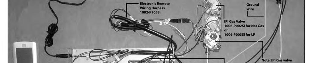
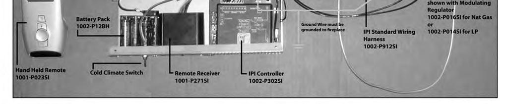
28 IPI Electronic Ignition System Overview The IPI system is an advanced burner controller that provides you with the option of having either a Standing-Pilot, or an intermittent igniting system. This alternating mode is controlled by the CPI/IPI Switch (Continuous Pilot Ignition/Intermittent Pilot Ignition) located on the IPI System Box. The difference between a Standing-Pilot and an Intermittent-Pilot is in whether the pilot stays lit or shuts off: In Standing-Pilot, the pilot assembly is lit by the IPI Main Module and continues to stay lit until 1) the CPI/IPI Switch is switched to the IPI position; 2) a loss of electrical power (battery and AC source), 3) the flame sensor loses its signal, 4) the fuel supply discontinues, or 5) the IPI Main Module malfunctions. In the Intermittent-Pilot mode, the pilot shuts off when the appliance is not in use. The advantage of this mode is that fuel is not consumed when the fireplace is not operating. NOTE: In some jurisdictions Intermittent-Pilot is required. That means the pilot cannot remain lit when the appliance is not operating. Components The core of the IPI system is the Main Module and the IPI Valve. With these two components the system is able to operate a gas fireplace. There are also other components available to complement the IPI system. IPI System Cover: Is essential in keeping the components at their proper operating temperatures. DO NOT OPERATE THE APPLIANCE WITHOUT THIS COVER. Modulating Servo Motor: Is an add-on valve component that permits HI/LO functionality to be controlled by the remote. Contrary to this feature is a Manual HI/LO Control Knob. The Modulating Servo Motor requires the Remote system to be present. Backup Battery Pack: This component permits the IPI system to operate without the need for an external AC Adapter power source. The advantage to using the battery backup is that in the case of a power failure, the appliance is still operable. NOTE: In certain instances the IPI Main Module requires resetting. This can occur if the system is unable to ignite the pilot or the main burner in the allotted time period. The IPI is programmed to lockout all commands. To reset this lockout you must deplete the system of all electrical power. This means to remove the batteries from the Battery Pack, remove the batteries from the Remote Receiver (if applicable), and disconnect the AC Adapter from the system. Leave the power off for approximately 25 seconds to clear its lockout. Remote Receiver: This component provides the capability of controlling the appliance with a wireless remote transmitter. Standing Pilot Mode for Colder Climates (Below Freezing) For IPI models it may be necessary to set the appliance to Standing Pilot mode to maintain heat in the cavity. The purpose of this procedure is to prevent cold air from penetrating the chimney and then onto the living space. Therefore, when the internal temperature is slightly elevated the fireplace is able to freely exhaust its combustion and hence making it easier to startup. 28


29 -Remote Control Operation- The Proflame GTM is configured to control the on/off main burner operation, its flame levels, and provides on/off and Smart thermostatic control of the appliance. Transmitter Remote Receiver Transmitter The Transmitter is powered by 3 AAA type batteries. A Mode Key is provided to Index between the features and a Thermostat Key is used to turn on/off or index through thermostat functions Remote Receiver The Receiver connects directly to the gas valve and stepper motor with a wiring harness. The Receiver is powered by 4 AA type batteries. The Receiver three position slider switch can be set to one of three positions: ON (Manual Override), Remote (Remote control) or Off. Initializing the System for the first time Install 4 AA batteries into the receiver battery bay. Install 3 AAA type batteries in the Transmitter battery bay. Place the 3 position slider switch in the Remote position. Insert the end of a paper clip into the hole marked PRG on the Receiver front cover. The Receiver will beep three (3) times to indicate that it is ready to synchronize with a Transmitter. Push the On button. The Receiver will beep four times to indicate the Transmitter s command is accepted. The system is now initialized. Temperature indication Display With the system in the OFF position, press the Thermostat Key and the Mode Key at the same time. Look at the LCD screen on the Transmitter to verify that a C or F is visible to the right of the Room Temperature display. Turn the Appliance On or Off Press the ON/OFF Key on the Transmitter Remote Flame Control The Proflame GTM has six (6) flame levels. Pressing the Down Arrow Key once will reduce the flame height by one step until the flame is turned off. The Up Arrow Key will increase the flame height each time it is pressed. If the Up Arrow Key is pressed while the system is on but the flame is off, the flame will come on in the high position. NOTE: The Remote Receiver module can also be located outside of the appliance to a maximum of 6ft away installed in a certified deep wall switch electrical box (2-3/4 depth). For this configuration an extension wiring harness (P/N: P904SI) is required. Room Thermostat ( Transmitter Operation) The Remote Control can operate as a room thermostat. To activate this function, press the Thermostat Key. The LCD display on the Transmitter will change to show that the room thermostat is ON and the set temperature is now displayed. To adjust the set temperature, press the Up or Down Arrow Keys until the desired set temperature is displayed on the LCD screen of the Transmitter. Smart Thermostat (Transmitter Operation) The Smart Thermostat function adjusts the flame height in accordance to the difference between the set point temperature and the actual room temperatures. As the room temperature gets closer to the set point the Smart Function will modulate the flame down. To activate this function, press the Thermostat Key until the word "SMART" appears to the right of the temperature bulb graphic. To adjust the set temperature, press the Up or Down arrow Keys until the desired set point temperature is displayed. Key Lock Function This function will lock the keys to avoid unsupervised operation. To activate this function, press the MODE and the UP Arrow Key at the same time. To de-activate this function, press the MODE and the UP Arrow Key at the same time. Low Battery Detection Transmitter - When the Transmitter batteries are low, a Battery Icon will appear on the LCD display of the Transmitter. Receiver - When the Receiver batteries are low, No beep will be emitted from the Receiver when it receives an On/Off command from the Transmitter. When the batteries are replaced the beep will be emitted from the Receiver when the ON/OFF Key is pressed (See Initializing the System for the first time). Manual Bypass Of The Remote System If the batteries of the Receiver or Transmitter are low or depleted, the appliance can be turned on manually by sliding the three position slider switch on the Receiver to the ON position. This will bypass the remote control feature and the appliance main burner will come on if the gas valve is in the On position. *In the U.S.A. Thermostats are not permitted for Vented Gas Fireplaces (ANSI Z21.50b Decorative)., 29
30 IPI Electronic Ignition Parts List Standard System Item No. Part No. Description P002si Valve IPI Hi/Lo NG 1006-P003si Valve IPI Hi/Lo LP P047si Pilot Assembly-LP 1002-P033si Pilot Assembly-NG P017si (*1002-P119si) Spark Electrode (with wire) P903si (*1002-P910si) Electrode Flame Sensor P302si IPI Ignition Board P850si AC Wall Adapter P12BH Battery Pack P912si Wiring Harness P166si Orifice Pilot -NG# P168si Orifice Pilot -LP# P013si Stepper Motor -NG 1002-P012si Stepper Motor -LP 1002-P016si Hi/Lo Regulator -NG 1002-P014si Hi/Lo Regulator -LP *Models MQRB5143E / MQRB6961E (35 Length) Proflame System Configuration: Manual Hi/Low Simplified Wire Diagram OR

31 Configuration #1: Basic manual HI/LO and manual ON/OFF capabilities. 31


32 Receiver Module /521/ P221SI Receiver Module /521/ P221SI 32
33 EGTM / GTM System -No Batteries -Wiring Harness P/N 1002-P906si required. -Millivolt Systems will also require Power Adapter P/N 1002-P850si. The Remote Receiver & IPI or Millivolt system can be powered by the AC Adapter. This is advantageous if you do not want to use batteries. Simply connect the AC Adapter into the Remote Control Wiring Harness as per the diagrams below. IPI System EGTM Receiver Module /521/ P221SI Millivolt System GTM Receiver Module /521/ P221SI 33


34 Configuration #3: Remote ON/OFF, variable HI/LO, and fan capabilities. Refer to the fan installation/removal section for fan installation. 34

35 Electronic Ignition Lighting Instructions If you do not follow these instructions exactly, a fire or explosion may result causing property damage, personal injury or loss of life. Always light the pilot whether for the first time or if the gas supply has ran out with the glass door opened or removed. FOR YOUR SAFETY READ BEFORE LIGHTING: A. This fireplace is equipped with an ignition device which automatically lights the pilot. Do not try to light by hand. B. Before operating smell all around the fireplace area for gas and next to the floor because some gas is heavier than air and will settle on the floor. C. Do not use this fireplace if any part has been under water. Immediately call a qualified service technician to inspect the fireplace and replace any part of the control system and any gas control which has been under water. WHAT TO DO IF YOU SMELL GAS: Turn off all gas to the fireplace. Open windows. Do not try to light any appliance. Do not touch any electric switch; do not use any phone in your building. Immediately call your gas supplier from a neighbor's phone. Follow the gas supplier's instructions. If you cannot reach your gas supplier, call the fire department. LIGHTING INSTRUCTIONS 1. Stop! Read the above safety information on this label. 2. Remove batteries from receiver, and/or Battery Backup Pack. 3. Turn off all electric power to the fireplace. 4. This fireplace is equipped with an ignition device which automatically lights the pilot. Do not try to light the pilot by hand. 5. Open the glass door Turn manual shutoff valve clockwise to off (Located behind the access panel). 7. Wait five (5) minutes to clear out any gas. If you smell gas including near the floor, STOP! Follow B in the above safety information on this label. If you don t smell gas go to the next step. 8. Turn manual shutoff valve counter-clockwise to on. 9. Close the glass door. 10. Turn on all electric power to the fireplace and re-install batteries into the Transmitter/Receiver, and/or Battery Backup Pack. 11. Turn On Switch that operates the Main Burner. If using a Remote Control refer to Remote Control Operation Manual for activation. TO TURN OFF GAS 1. Turn off all electric power to the fireplace if service is to be performed, including removing batteries from Remote Transmitter/Receiver and/or Battery Backup Pack. 2. Access door inside the firebox must be removed to access the manual shutoff valve. 3. If alternate shut-off valve was installed it can be shutoff instead of going through the fireplace to access the fireplace shut off valve. 35
36 Vent Instructions NOTE: A chimney venting this fireplace shall not vent any other appliance. This appliance may be vented into various types of applications: A Vent of solid fuel wood burning chimney, Masonry Clay lining and B Vent liquid fuel gas chimney. NOTE: Four (4) inch is required if existing chimney is five (5) inches or larger. Four (4) inch single wall or B Vent liquid fuel gas chimney may be used to adapt existing chimney or liner to fireplace. Single wall pipe must have 6 clearance to combustibles When installing with B Vent liquid fuel gas chimney install as per B Vent Manufacturer Installation specifications. Offset vertical or vertical installations may be installed. NOTE: Installation of B Vent must follow B Vent Manufactures s Installation instructions when being used. Seal all connections in venting system. Chimney Installations Three types of chimney systems may be used with this unit. A chimney venting this fireplace shall not vent any solid fuel burning appliance. 36
37 Parts List 3600ZV Parts List 4200ZV PART NO. DESCRIPTION PART NO. DESCRIPTION ZV3600N Fireplace Decorative Top Flue (as above) NG, Tempered Glass, 21,000 BTU ZV3600LP Fireplace Decorative Top Flue (as above) LP, Tempered Glass, 20,000 BTU Log Sets: (Required for each unit) LOGC42 Log Set - Four Piece - Classic Oak LOGC43 Log Set - Four Piece - Traditional Oak LOGC44 Log Set - Eight Piece - Burnt Oak Grills: (Required for each unit) Z36GBA Grill Kit - Classic Builder Antique Brass Z36GBC Grill Kit - Classic Builder Chrome Z36GBP Grill Kit - Classic Builder Polish Brass Z1GBL Grill Kit - Black Z1GAB Grill Kit - Antique Brass Z1GPB Grill Kit - Polish Brass Z36GCR Grill Kit - Chrome Fireplace Accessories Options: Z36SAB Surround - Antique Brass (Coverage Old Style 33 3/4" H x 39 7/8" W) Z36SCR Surround - Chrome (Coverage New Style 34 1/2" H x 41 1/8" W) Z36SPB Surround - Polish Brass (Coverage New Style 33 1/2" H x 41 1/8" W) Z36SLAB Surround Slim Line - Antique Brass (Coverage 34 1/4" H x 37 1/2" W) Z36SLCR Surround Slim Line - Chrome (Coverage 34 1/4" H x 37 1/2" W) Z36SLPB Surround Slim Line - Polish Brass (Coverage 34 1/4" H x 37 1/2" W) Z36SLBL Surround Slim Line - Gun Metal Black (Coverage 34 1/4" H x 37 1/2" W) Z36ADDX Arch Door Frame - Deluxe Black (352) Z36ADTH Arch Door Frame - Top half Black (353T) Refractory Liner Z36RL Refractory Liner Designer Doors for 36 Fireplaces - Operative Z36DDA1BL Designer Door Arch - Series 1 - Black Z36DDS1BL Designer Door Straight - Series 1 - Black Child Safety Screen Z36CSS Child Safety Screen - 36 DV Fireplaces Replacement Burner Assembly 36ZV-BNGSI Burner Assembly ZV3600N-SIT 36ZV-BLPSI Burner assembly ZV3600LP-SIT Conversion Kit (SIT Valve only) 3600ZV-CKLP LP Conversion Kit for ZV3600LP 3600ZV-CKNG NG Conversion Kit for ZV3600N 3600ZV-CKLPI LP Conversion Kit for ZV3600LPE 3600ZV-CKNGI NG Conversion Kit for ZV3600NE Door Glass Tempered Glass (ZV3600) ZV4200N Fireplace Decorative Rated (as above) NG, Tempered Glass, 21,000 BTU ZV4200LP Fireplace Decorative Rated (as above) LP, Tempered Glass, 20,000 BTU Log Sets: (Required for each unit) LOGC42 Log Set - Four Piece - Classic Oak LOGC43 Log Set - Four Piece - Traditional Oak LOGC44 Log Set - Eight Piece - Burnt Oak Grills: (Required for each unit) Z42GBA Grill Kit - Classic Builder Antique Brass Z42GBC Grill Kit - Classic Builder Chrome Z42GBP Grill Kit - Classic Builder Polish Brass Z42GBL Grill Kit - Black Z42GAB Grill Kit - Antique Brass Z42GPB Grill Kit - Polish Brass Z42GCR Grill Kit - Chrome Fireplace Accessories Options: Z42SAB Surround - Antique Brass (Coverage 36 5/8" H x 45 1/8" W) Z42SCR Surround - Chrome (Coverage 36 5/8" H x 45 1/8" W) Z42SPB Surround - Polish Brass (Coverage 36 5/8" H x 45 1/8" W) Z42SLAB Surround Slim Line - Antique Brass (Coverage 36 3/8" H x 43 3/8" W) Z42SLCR Surround Slim Line - Chrome (Coverage 36 3/8" H x 43 3/8" W) Z42SLPB Surround Slim Line - Polish Brass (Coverage 36 3/8" H x 43 3/8" W) Z42SLBL Surround Slim Line - Gun Metal Black (Coverage 36 3/8" H x 43 3/8" W) Z42ADDX Arch Door Frame - Deluxe Black (352) Z42ADTH Arch Door Frame - Top Half Black (353T) Refractory Liner Z42RL Refractory Liner Designer Doors for 42 Fireplaces - Operative Z42DDA1BL Designer Door Arch - Series 1 - Black Z42DDS1BL Designer Door Straight - Series 1 - Black Child Safety Screen Z42CSS Child Safety Screen - 42 DV Fireplaces Replacement Burner Assembly 42ZV-BNGSI Burner assembly ZV4200N-SIT 42ZV-BLPSI Burner assembly ZV4200LP-SIT Conversion Kit (SIT Valve only) 4200ZV-CKLP LP Conversion Kit for ZV4200LP 4200ZV-CKNG NG Conversion Kit for ZV4200N 4200ZV-CKLPI LP Conversion Kit for ZV4200LPE 4200ZV-CKNGI NG Conversion Kit for ZV4200NE Door Glass Tempered Glass (ZV4200) 37
38 Parts List Common Parts 3600ZV & 4200ZV PART NO. DESCRIPTION PART NO. DESCRIPTION Valve System Parts - SIT NOVA (If Serial Number is LESS than 36184) 1000-P136WR Thermopile GOAI P035SI Electrode Sparker SIT 1001-P129SI Thermocouple SIT unified 1001-P157SI Orifice Pilot LP SIT 1001-P159SI Orifice Pilot NG SIT 1001-P508SI HT Cable P633SI Valve Nova LP Hi/Lo P634SI Valve Nova NG Hi/Lo P605SI Pilot Burner LP unified SIT 1001-P606SI Pilot Burner NG unified SIT Valve System Parts - SIT NOVA New top convertible SIT (If Serial Number is between ) 1000-P136WR Thermopile GOAI P069SI Electrode Sparker TC SIT 1001-P216SI Thermocouple TC SIT 1001-P165SI Orifice Pilot NG TC SIT 1001-P167SI Orifice Pilot LP TC SIT 1001-P508SI HT Cable P508SI HT Cable P633SI Valve Nova LP Hi/Lo P634SI Valve Nova NG Hi/Lo P713SI Pilot Burner LP TC SIT 1001-P714SI Pilot Burner NG TC SIT Valve System Parts - SIT NOVA New SIT TC True Millivolt (If Serial Number is GREATER than above) 1000-P136WR Thermopile GOAI P069SI Electrode Sparker TC SIT 1001-P165SI Orifice Pilot NG TC SIT 1001-P167SI Orifice Pilot LP TC SIT 1001-P639SI Valve Nova LP Hi/Lo True MV 1001-P640SI Valve Nova NG Hi/Lo True MV 1001-P745SI Pilot Burner LP TC TM 1001-P746SI Pilot Burner NG TC TM Miscellaneous Parts #Piezo-Igniter MARK #Pal Nut (18MMXI.5MM)BLK ( ) #Switch Ivory (1451/001) #Cover Ivory (86001/001) #Orifice Brass - (State Size) #Explosion Felt Gasket #Thermo Disc 2450 (For Blower) #Control Variable Speed KBWC-13BV Thermalcord - Adhesive Back for Door Frame Ceramic Glass - For All ZDV ZV-P300TD Spill Switch Z65FAK Fresh Air Kit GE Silicone GE Red IS806 # MP Hi-Temp Millpac Sealant Control Variable Speed KBWC-13BV FP15GC Stainless Steel Gas Connector Accessories Z1MT Thermostat Millivolt Wall Mount Z80PT Thermostat Programmable Digital Millivolt Wall Mount (1F80-40) DCHS Remote Control Heatshield *In the U.S.A. Thermostats are not permitted for Vented Gas Fireplaces (ANSI Z21.50b Decorative). Remote Control / Millivolt GFRC Remote Control Millivolt / IPI On/Off GTRC Remote Control Millivolt - Thermostat GTMRCN Remote Control Millivolt Thermostat/Modulating - NG GTMRCP Remote Control Millivolt Thermostat/Modulating - LP GTFRCN Remote Control Millivolt Thermostat/Modulating/Fan - NG GTFRCP Remote Control Millivolt Thermostat/Modulating/Fan - LP Electronic Ignition/Remote Control IPI EGTRC Remote Control IPI (Thermostat) EGTMRCN Remote Control IPI (Thermostat/Modulating - NG) EGTMRCP Remote Control IPI (Thermostat/Modulating - LP) EGTFRCN Remote Control IPI (Thermostat/Modulating/Fan - NG) EGTFRCP Remote Control IPI (Thermostat/Modulating/Fan - LP) Electronic Ignition Replacement Parts IPI 1006-P002si Valve IPI (NG; Hi/Lo) 1006-P003si Valve IPI (LP; Hi/Lo) 1002-P047si Pilot Assembly (LP) 1002-P033si Pilot Assembly (NG) 1002-P017si Spark Electrode 1002-P903si Electrode Flame Sensor 1002-P302si IPI Ignition Board 1002-P850si AC Wall Adapter 1002-P12BH Battery Pack 1002-P912si Wiring Harness 1001-P166si Orifice Pilot (NG) 1001-P168si Orifice Pilot (LP) 1002-P013si Stepper Motor (NG) 1002-P012si Stepper Motor (LP) 1002-P016si Hi/Lo Regulator (NG) 1002-P014si Hi/Lo Regulator (LP) Valve System Parts - Honeywell 1001-P8520EN Valve hi/lo-ng- HONEYWELL 1001-P8520EP Valve hi/lo-lp - HONEYWELL Fan Kit / Blower Z33FK Fan Kit w/variable Speed Wall Mount Control (Temperature Sensing) 38
39 Trouble Shooting The Gas Control System WARNING: BEFORE DOING ANY GAS CONTROL SERVICE WORK, REMOVE THE GLASS FRONT. NOTE: Before troubleshooting the gas control system, be sure external gas shut off is in the On position. Problem Possible Causes Corrective Action Spark igniter will not light. Defective or misaligned Check for spark at electrode and pilot: if no spark and electrode electrode at pilot. wire is properly connected, replace igniter. Defective igniter (push-button) Using a match, light pilot. If pilot lights, turn off pilot and push the red button again. If pilot will not light - check gap at electrode and pilot should be 1/8 to 1/4 to have a strong spark. Pilot will not stay lit after carefully Defective safety spill switch Check pilot flame. Must impinge on generator and thermocouple. following lighting instructions. Clean and/or adjust pilot for maximum flame impingement on generator and thermocouple. Be sure wire connections from spill safety switch are connected securely to wires on back of valve. If pilot still doesn t light, unplug spill switch wires at valve and then plug thermocouple wires (blue in color) together. If this works, the spill switch is defective. Defective thermocouple Replace thermocouple Defective valve magnet. Turn valve knob on On, place wall switch on On. Millivolt meter should read greater than 100mV. If the reading is okay and the burner does not come on, replace the gas valve. Pilot burning, no gas to burner, Wall switch or wires Check wall switch and wires for proper connections. Jumper wire Valve knob ON, Wall defective. across terminals at wall switch. If burner comes on, replace Switch ON defective wall switch. If okay, jumper wires, across wall switch wires at valve. If burner comes on, wires are faulty or connec tions are bad. Generator may not be Check generator with millivolt meter. Take reading at generator generating sufficient voltage. terminals of gas valve. Should read 325 millivolts minimum while holding valve knob depressed in pilot position and wall switch off Replace faulty generator if reading is below specified minimum. Plugged burner orifice. Check burner orifice for stoppage and remove. Defective automatic valve Remove wall switch wires from gas valve. Install jumper wires operator. from top bottom terminals of gas valve. Turn valve on ON. If main burner does not light, replace valve. Frequent Pilot outage problem. Pilot flame may be too low or Clean and/or adjust pilot flame for maximum flame impingement blowing (high) causing the pilot on generator and thermocouple. safety to drop out. 39

40 -Glass Safety- All Units IT IS THE RESPONSIBILITY OF THE HOME OWNER TO ENSURE THAT NO ONE TOUCHES A HOT APPLIANCE. Optional safety screens are available for most appliances. Check with your dealer to find out if one is available for your unit, or if an aftermarket free standing safety screen is available. Children and adults should be alerted to the hazards of the high surface temperatures of this appliance and should stay away to avoid burns or ignition of clothing. Do not clean when the glass is hot. Young children should be carefully supervised when they are in the same room as the appliance. Toddlers, young children and others may be susceptible to accidental contact burns. A physical barrier is recommended if there are at risk individuals in the house. To restrict access to a fireplace or stove, install an adjustable safety gate to keep toddlers, young children and other at risk individuals out of the room and away from hot surfaces. Do not leave the fireplace remote control where it is accessible to children. 40

41 This Limited Lifetime Warranty applies only while the unit remains at the site of the original installation and only if the unit is installed inside the continental United States, Alaska, Hawaii, and Canada. The warranty applies only if the unit is installed and operated in accordance with the printed instructions and in compliance with applicable installation and building codes and good trade practices. BASIC ONE YEAR WARRANTY During the first year after installation, we will provide a replacement for any component part of your unit found to be defective in materials or workmanship, including labour costs. Repair work requires prior approval by Kingsman, labour costs are based on a predetermined rate schedule and any repair work must be done through an authorized Kingsman dealer. LIMITED LIFETIME WARRANTY The heat exchanger, combustion chamber and burner of every Kingsman product excluding the Outdoor Firepit are warranted against materials or workmanship during the period the product is owned by the original owner. The part to be replaced must be returned to our distributor in exchange for the replacement part. Any labor, material, freight and/or handling charges associated with any repair or replacement pursuant to this Limited Lifetime Warranty will not be covered by this warranty. GENERAL TERMS In lieu of providing a replacement part, we may, at our option, provide the distributor's component purchase price from us or a credit equal to the distributors component purchase price from us toward the purchase of any new unit which we distribute. If a credit is given in lieu of a replacement part, the rating plate from the unit being replaced must be submitted on a warranty claim, and the unit being replaced must be made available to our distributor for disposition. In establishing the date of installation for any purpose, including determination of the starting date for the term of this Limited Lifetime Warranty, reasonable proof of the original installation date must be presented*, otherwise the effective date will be based upon the date of manufacture plus thirty (30) days. We will not be responsible for and you, the user, will pay for: (a) damages caused by accident, abuse, negligence, misuse, riot, fire, flood, or Acts of God (b) damages caused by operating the unit where there is a corrosive atmosphere containing chlorine, fluorine, or any other damaging chemicals (other than in a normal residential environment) (c) damages caused by any unauthorized alteration or repair of the unit affecting its stability or performance (d) damages caused by improper matching or application of the unit or the unit's components (e) damages caused by failing to provide proper maintenance and service to the unit (f) any expenses incurred for erecting, disconnecting or dismantling the unit (g) parts or supplies used in connection with service or maintenance (h) damage repairs, inoperation or inefficiency resulting from faulty installation or application (i) electricity or fuel costs or any increase in electricity or fuel cost whatsoever including additional or unusual use of supplemental electric heat. We shall not be liable for any incidental, consequential, or special damages or expenses in connection with any use or failure of this unit. We have not made and do not make any representation or warranty of fitness for a particular use or purpose, and there is no implied condition of fitness for a particular use or purpose. We make no express warranties except as stated in this Limited Lifetime Warranty. No one is authorized to change this Limited Lifetime Warranty or to create for us any other obligation or liability in connections with this unit. Any implied warranties shall last for one year after the original installation. Some states and provinces do not allow the exclusion or limitation of incidental or consequential damages or do not allow limitations on how long an implied warranty or condition lasts, so the above limitations or exclusions may not apply to you. The provisions of this limited warranty are in additions to and not a modification of or subtraction from any statutory warranties and other rights and remedies provided by law. Save this certificate. It gives you specific legal rights, and you may also have other rights which may vary from state to state and province to province. In the event your unit needs servicing, contact your dealer or contractor who installed or serviced your unit. When requesting service, please have the model and serial number from each unit readily available. If your dealer needs assistance, the distributor is available for support and we, in turn support the distributor's efforts. Fill in the installation date and model and serial numbers of the unit in the space provided below and retain this limited warranty for your files. Model No. Serial No. Date installed Dealer or Contractor Name: *To receive advantage of your warranty, you must retain the original records that can establish the installation date of your unit. The Ultimate in Design, Engineering & Quality 41
Read this complete manual before beginning installation. These instructions must be kept with the unit for future reference.
 Installation Instructions Listed Certified for USA and Canada Model Number: MQZDV1917 Stock # s: MQZDV1917N, MQZDV1917LP, MQZDV1917NE, MQZDV1917LPE Certified to: ANSI Z21.88-2009, CSA 2.33-2009, CGA 2.17-M91
Installation Instructions
 Installation Instructions Model Number HBZDV4740 Zero Clearance Direct Vent Fireplace Stock # s: HBZDV4740N, HBZDV4740LP, HBZDV4740NE, HBZDV4740LPE are Certified to: ANSI Z21.50b-2009, CSA 2.22b-2009,
Installation Instructions
 Installation Instructions Model Numbers: ZCV3622N, ZCV3622NE, ZCV3622LP, ZCV3622LPE ZCVRB3622N, ZCVRB3622NE, ZCVRB3622LP, ZCVRB3622LPE, Certified to: ANSI Z21.88-2014 CSA 2.33-2014 ZERO CLEARANCE VENTED
Installation Instructions
 Model Numbers: Installation Instructions ZCV39N, ZCV39NE, ZCV39LP, ZCV39LPE ZCV42N, ZCV42NE, ZCV42LP, ZCV42LPE Certified to: ANSI Z21.50-2014 CSA 2.22-2014 ZERO CLEARANCE VENTED GAS FIREPLACE BENTLEY Model
INSTALLER: Leave this manual with the appliance. CONSUMER: Retain this manual for future reference.
 Installation Instructions Model Number VFI30 Gas Fired Room Heater Insert Model VFI30 Listed Certified for USA. and Canada Minimum Fireplace Opening Required: 29 W x 20-3/4 H x 16-1/2 D Certified to: ANSI
Infinite Series Installation Instructions
 Model Numbers: Certified to: Infinite Series Installation Instructions MQRB4436N, MQRB4436NE, MQRB4436LP, MQRB4436LPE MQRB5143N, MQRB5143NE, MQRB5143LP, MQRB5143LPE MQRB6961N, MQRB6961NE, MQRB6961LP, MQRB6961LPE
For Propane Horizontal installations the venting must be a minimum of one foot vertical off the flue before going horizontal.
 Solara Installation Instructions Listed Certified for USA and Canada Model Numbers MQZDV3318, MQZDV3622 Zero Clearance Direct Vent Gas Fireplace Stock # s: MQZDV3318N, MQZDV3318NE, MQZDV3318LP, MQZDV3318LPE,
INFINITY Manufactured by R-Co for Fiamma
 Fiamma LLC. Installation Instructions INFINITY Manufactured by R-Co for Fiamma Model Numbers: Stock Numbers: Certified to: MQRB5143, MQRB6961 MQRB5143N, MQRB5143NE, MQRB5143LP, MQRB5143LPE MQRB6961N, MQRB6961NE,
Installation Instructions Model Number FDV350 Free Standing Direct Vent Gas Stove (Field Convertible to Vented Stove)
") Model Numbers: Installation Instructions Model Number FDV350 Free Standing Direct Vent Gas Stove (Field Convertible to Vented Stove) FDV350N, FDV350NE, FDV350NE2, FDV350LP, FDV350LPE, FDV350LPE2 Certified
Model Numbers: Installation Instructions Model Number FDV350 Free Standing Direct Vent Gas Stove (Field Convertible to Vented Stove) FDV350N, FDV350NE, FDV350NE2, FDV350LP, FDV350LPE, FDV350LPE2 Certified
Zero Clearance Vented Gas Fireplace
 Installation Instructions Listed Certified for USA. and Canada Certified to: ANSI Z21.50a-1992, Can1-2.19-M81, CGA, CAN/CGA 2.17-1991 Model Number ZV6500 Stock # s: ZV6500N, ZV6500LP Zero Clearance Vented
Installation Instructions Model Number ZRB46 Zero Clearance Vented Gas Fireplace Heater
 Installation Instructions Model Number ZRB46 Zero Clearance Vented Gas Fireplace Heater Stock # s: ZRB46N, ZRB46NE, ZRB46LP, ZRB46LPE Conforms to: ANSI Z21.88-2016 CSA 2.33-2016 ZERO CLEARANCE VENTED GAS
Installation Instructions
 Installation Instructions Model Number HBZDV4224, HBZDV4228, HBZDV4232 Stock # s: HBZDV4224N, HBZDV4224LP are Certified to: ANSI Z21.50-2014 CSA 2.22-2014 ZERO CLEARANCE VENTED GAS FIREPLACE Stock # s:
MODELS LFP4218/LFP6018 TOP VENT GAS FIREPLACE
 MODELS LFP4218/LFP6018 TOP VENT GAS FIREPLACE PFS APPROVED FOR NATURAL GAS OR PROPANE GAS Z21.50-2014 If your plans do not allow for the venting system as outlined previously in the installing chimney/vent
Models #CSK-31 #CSK-31-RF. CHASKA Direct Vent Gas Fireplace Insert INSTALLATION & OPERATING MANUAL
 WARNING: If the information in these instructions are not followed exactly, a fire or explosion may result causing property damage, personal injury or loss of life. Models #CSK-31 #CSK-31-RF CHASKA Direct
Installation Instructions Model Number ZDV3318, ZDV3622, ZDVRB3622 Zero Clearance Direct Vent Fireplace
 Installation Instructions Model Number ZDV3318, ZDV3622, ZDVRB3622 Zero Clearance Direct Vent Fireplace Stock # s: ZDV3318N, ZDV3318NE, ZDV3318LP, ZDV3318LPE ZDV3622N, ZDV3622NE, ZDV3622LP, ZDV3622LPE
Infinite Series. Installation Instructions
 Model Numbers: Infinite Series Installation Instructions MQRB4436N, MQRB4436NE, MQRB4436LP, MQRB4436LPE MQRB5143N, MQRB5143NE, MQRB5143LP, MQRB5143LPE MQRB6961N, MQRB6961NE, MQRB6961LP, MQRB6961LPE Certified
SIERRA RADIANT HEAT MAJESTIC OAK VENTED GAS LOG KIT INSTALLATION AND OPERATING INSTRUCTIONS
 SIERRA RADIANT HEAT MAJESTIC OAK VENTED GAS LOG KIT INSTALLATION AND OPERATING INSTRUCTIONS WARNING: If the information in this manual is not followed exactly, a fire or explosion may result causing property
Models #CSK-335 #CSK-335-RF. CHASKA - XL Direct Vent Gas Fireplace Insert INSTALLATION & OPERATING MANUAL
 WARNING: If the information in these instructions are not followed exactly, a fire or explosion may result causing property damage, personal injury or loss of life. Models #CSK-335 #CSK-335-RF CHASKA -
OUTDOOR FIREPLACE MANUAL
 OUTDOOR FIREPLACE MANUAL Models: OFP42N, OFP42LP, OFP42NS, OFP42LPS Certified For USA & Canada Standards: CSA 4.96 US 2nd Edition, CGA CR97-003, CGA 2.17-M91 Outdoor Gas Fireplaces Owner s Operation and
Installation/Operating Instructions
 Installation/Operating Instructions Models: 4072-180 24 NG 4072-182 30 NG Outdoor Hearth Kit DO NOT DISCARD INSTALLER: Leave this manual with party responsible for use and operation. OWNER: Retain this
Installation Instructions
 Model Numbers: Installation Instructions MQZCV48N, MQZCV48NE, MQZCV48NE2, MQZCV48LP, MQZCV48LPE, MQZCV48LPE2, Certified to: ANSI Z21.88-2016 CSA 2.33-2016 VENTED GAS FIREPLACE HEATER BENTLEY This appliance
#CSK-31-RF. CHASKA Direct Vent Gas Fireplace Insert INSTALLATION & OPERATING MANUAL
 Models #CSK-31 #CSK-31-RF CHASKA Direct Vent Gas Fireplace Insert INSTALLATION & OPERATING MANUAL WARNING: If the information in these instructions is not followed exactly, a fire or explosion may result,
Using it in an enclosed space can kill you.
 38 X 56 GAS FIRE PIT - OWNER S MANUAL Carlisle Chat Fire Table Base Model # 00GBC7 (6877B) Fits 6877A Carlisle Chat Fire Table Top For Propane and *Natural Gas (*See Page 7) Certified to CSA International
Installation Instructions Model Number VRB46 Zero Clearance Vented Gas Fireplace Heater
 Installation Instructions Model Number VRB46 Zero Clearance Vented Gas Fireplace Heater Stock # s: VRB46N, VRB46NE, VRB46LP, VRB46LPE Conforms to: ANSI Z21.88-2016 CSA 2.33-2016 VENTED GAS FIREPLACE HEATER
Installation Instructions
 Model Numbers: Installation Instructions MQZCV48N, MQZCV48NE, MQZCV48NE2, MQZCV48LP, MQZCV48LPE, MQZCV48LPE2, Certified to: ANSI Z21.88-2016 CSA 2.33-2016 VENTED GAS FIREPLACE HEATER BENTLEY This appliance
Multi-Sided Direct Vent Decorative Gas Fireplace
 Installation Instructions Listed Certified for USA. and Canada Models MDV30/38 Certified to: ANSI Z21.50-1996/CGA 2.22-M96, CAN/CGA 2.17-M91, CSA P.4.1-02 Model MDV31 Series - MDVR31N, MDVR31LP, MDVL31N,
CAPRI. INSTALLER: Leave this manual with the appliance. CONSUMER: Retain this manual for future reference.
 Installation Instructions Gas Fireplace Insert Heater Listed Certified for USA. and Canada Model Numbers: IDV34 - Stock Numbers: IDV34N, IDV34NE, IDV34NE2, IDV34LP, IDV34LPE, IDV34LPE2 Minimum Fireplace
Installation Instructions Gas Fired Direct Vent Room Heater Inserts Listed Certified for USA. and Canada
 Model Numbers: Installation Instructions Gas Fired Direct Vent Room Heater Inserts Listed Certified for USA. and Canada IDV26 Stock Numbers: IDV26N, IDV26NE, IDV26NE2, IDV26LP, IDV26LPE, IDV26LPE2 Minimum
Installation and service must be provided by a qualified installer, service agency or the gas supplier.
 INSTALLATION AND OPERATION GUIDE FOR OLDE WORLD BASKET Vented Decorative Appliance For all models tested through PFS Corporation, to ANSI Z21.60-2003/CGA 2.26-2003, Decorative Appliance for Installation
INSTALLATION OPERATION AND SERVICE MANUAL
 INSTALLATION OPERATION AND SERVICE MANUAL THE OLD SALEM COLLECTION VENT FREE REGENCY COAL BASKET complies with ANSI Z21.11.2 THIS ONLINE MANUAL IS FOR PLANNING PUPOSES ONLY. CAREFULLY READ BEFORE PURCHASING.
INSTALLATION AND OPERATING MANUAL
 WARNING: If the information in these instructions is not followed exactly, a fire or explosion may result, causing property damage, personal injury or loss of life. MODEL: #56701 Thief River Falls - TRF
OVATION SERIES FIRE TABLES ASSEMBLY INSTRUCTIONS
 OVATION SERIES FIRE TABLES ASSEMBLY INSTRUCTIONS CSA Model98900 DRS02403 Installer: Leave these instructions with consumer. Consumer: Keep these instructions for future reference. DANGER If you smell gas:
Installation Instructions
 Installation Instructions Model Number VFI25 Gas Fired Room Heater Insert Model VFI25 Listed Certified for USA. and Canada Minimum Fireplace Opening Required: 24 W x 17-1/2 H x 16 D Certified to: ANSI
Heat-N-Glo Fireplace. Installers Guide. Model: AT-GRAND
 Heat-N-Glo Fireplace Model: AT-GRAND Installers Guide Patents Pending Underwriters Laboratories Listed WARNING: IF THE INFORMATION IN THESE INSTRUCTIONS IS NOT FOLLOWED EXACTLY, A FIRE OR EXPLOSION MAY
INSTALLATION AND OPERATING MANUAL
 WARNING: If the information in these instructions is not followed exactly, a fire or explosion may result, causing property damage, personal injury or loss of life. MODELS: #PRC-36 / #PRC-36-RF PRINCETON
Heat-N-Glo. Installers Guide. Model: 8000TVC
 Model: 8000TVC Heat-N-Glo Installers Guide Underwriters Laboratories Listed WARNING IF THE INFORMATION IN THESE INSTRUCTIONS IS NOT FOLLOWED EXACTLY, A FIRE OR EXPLOSION MAY RESULT CAUSING PROPERTY DAMAGE,
Owner s Guide Installation & Operation
 Owner s Guide Installation & Operation Char Broiler HCH Series Hestan Commercial Corporation 3375 E. La Palma Ave Anaheim, CA 92806 (888) 905-7463 RETAIN THIS MANUAL FOR FUTURE REFERENCE P/N 002134 REV
Installation Instructions Model Number FDV451 & MQFDV453 Free Standing Direct Vent Gas Stove
 Installation Instructions Model Number FDV451 & MQFDV453 Free Standing Direct Vent Gas Stove Stock # s: FDV451N, FDV451NE, FDV451LP, FDV451LPE, MQFDV453N, MQFDV453NE, MQFDV453LP, MQFDV453LPE are Certified
Installation Instructions
 Installation Instructions Models: ODGO324-MTCH, Grand Oak Match Light Gas Log Sets Installation and service of this appliance should be performed by qualified personnel. Hearth & Home Technologies suggests
INSTALLATION INSTRUCTIONS AND OWNER S MANUAL
 INSTALLATION INSTRUCTIONS AND OWNER S MANUAL DRIFTWOOD LOG SET FOR UNVENTED GAS LOG HEATER OR VENTED DECORATIVE APPLIANCE MODELS LS18CD-1 LS24CD-1 LS30CD-1 GAS-FIRED LS24CD Shown INSTALLER: Leave this
GAS -FIRED VENTED ROOM HEATERS MODEL 61TV
 GAS -FIRED VENTED ROOM HEATERS MODEL 61TV INSTALLATION MANUAL NEW BUCK CORPORATION WARNING: Improper installation, adjustment, alteration,service or maintenance can cause injury or property damage. Refer
INSTALLER: Leave this manual with the appliance. CONSUMER: Retain this manual for future reference.
 Installation Instructions Model Number ZDV6000, ZDV3320 MQRB3328 Zero Clearance Direct Vent Gas Fireplace Stock # s ZDV3320N, ZDV3320LP, ZDV3320NE, ZDV3320LPE, are Certified to: ANSI Z21.50b-2009, CSA
Hanover Outdoor Furniture IMPORTANT. If you have any problems with this product (missing or damaged parts, assembly issues, etc.),
,") Hanover Outdoor Furniture IMPORTANT If you have any problems with this product (missing or damaged parts, assembly issues, etc.), PLEASE DO NOT RETURN TO THE RETAILER/STORE from where you purchased the
Hanover Outdoor Furniture IMPORTANT If you have any problems with this product (missing or damaged parts, assembly issues, etc.), PLEASE DO NOT RETURN TO THE RETAILER/STORE from where you purchased the
Owner s Guide Installation & Operation
 Owner s Guide Installation & Operation Hot Top HHT Series Hestan Commercial Corporation 3375 E. La Palma Ave Anaheim, CA 92806 (888) 905-7463 RETAIN THIS MANUAL FOR FUTURE REFERENCE P/N 002130 REV 1 IMPORTANT
CATALINA FIRE TABLE ASSEMBLY INSTRUCTIONS
 CATALINA FIRE TABLE ASSEMBLY INSTRUCTIONS CSA Model 98300 DRF01000 Installer: Leave these instructions with consumer. Consumer: Keep these instructions for future reference. DANGER If you smell gas: 1.
INSTALLER: Leave this manual with the appliance. CONSUMER: Retain this manual for future reference.
 Installation Instructions Model Numbers MDV31/39/MQRB3632 Multi-Sided Direct Vent Decorative Gas Fireplace Certified to: ANSI Z21.50-2014 CSA 2.22-2014 Model MDV31 Series - MDVR31N, MDVR31LP, MDVL31N,
Legend VENTED GAS FIREPLACE HEATERS
 MODEL 937XN FOR USE WITH NATURAL GAS Legend MODEL 937XP FOR USE WITH PROPANE VENTED GAS FIREPLACE HEATERS WARNING: If the information in this manual is not followed exactly, a fire or explosion may result
INSTALLATION GUIDE Dual Fuel Ranges
 INSTALLATION GUIDE Dual Fuel Ranges Contents Wolf Dual Fuel Ranges......................... 3 Safety Instructions............................ 4 Dual Fuel Range Specifications.................. 5 Dual Fuel
INSTALLER: Leave this manual with the appliance. CONSUMER: Retain this manual for future reference.
 Installation Instructions Model Number FDV451 & MQFDV453 Free Standing Direct Vent Gas Stove Stock # s: FDV451N, FDV451NE, FDV451LP, FDV451LPE, MQFDV453N, MQFDV453NE, MQFDV453LP, MQFDV453LPE are Certified
CAUTION FOR YOUR SAFETY
 VENT-FREE GAS FIREBOX Model # PC32VFC & PC36VFC CAUTION FOR YOUR SAFETY WARNING: IF THE INFORMATION IN THIS MANUAL IS NOT FOLLOWED EXACTLY, A FIRE MAY RESULT CAUSING PROPERTY DAMAGE, PERSONAL INJURY, OR
INSTALLATION AND OPERATING MANUAL
 WARNING: If the information in these instructions is not followed exactly, a fire or explosion may result, causing property damage, personal injury or loss of life. MINNETONKA Direct Vent Gas Fireplace
Installation Instructions Model Number VRB46 Zero Clearance Vented Gas Fireplace Heater
 Installation Instructions Model Number VRB46 Zero Clearance Vented Gas Fireplace Heater Stock # s: VRB46N, VRB46NE, VRB46LP, VRB46LPE Conforms to: ANSI Z21.88-2016 CSA 2.33-2016 VENTED GAS FIREPLACE HEATER
WALL MOUNTED ELECTRIC FIREPLACE HEATER. Model # : Onyx Ivory Mirror OWNER S MANUAL. AC V 60Hz 1500W
 WALL MOUNTED ELECTRIC FIREPLACE HEATER Model # : 80001 Onyx 80002 Ivory 80008 - Mirror OWNER S MANUAL AC 110-120V 60Hz 1500W WARNING Read and understand this entire owner s manual, including all safety
Owner s Manual Installation and Operation
 Owner s Manual Installation and Operation Model: ST-42TVFL-IPI CAUTION DO NOT DISCARD THIS MANUAL Important operating Read, understand and follow Leave this manual with and maintenance these instructions
INSTALLATION INSTRUCTIONS AND OWNER'S MANUAL
 INSTALLATION INSTRUCTIONS AND OWNER'S MANUAL RAVENWOOD LOG SET FOR UNVENTED GAS LOG HEATER OR VENTED DECORATIVE APPLIANCE STANDARD MODELS ALS18RV-1 ALS24RV-1 ALS30RV-1 GAS-FIRED SELECT MODELS ALS24RVS-1
Owner s Operation and Installation Manual
 Owner s Operation and Installation Manual INSTALLER: Leave this manual with the appliance. CONSUMER: Retain this manual for future reference. Models ZVFCV39, ZVFCV42, ZVFCV47 Certified to: ANSI Z21.91-2007
ASSEMBLY INSTRUCTIONS
 ASSEMBLY INSTRUCTIONS Installer: Leave these instructions with consumer. Consumer: Keep these instructions for future reference. WARNING: If the information in this manual is not followed exactly, a fire
INSTALLATION AND OPERATING MANUAL
 INSTALLATION AND OPERATING MANUAL INSTALLER: LEAVE THIS MANUAL WITH THE APPLIANCE. CONSUMER: RETAIN THIS MANUAL FOR FUTURE REFERENCE. GAS FIREPLACE WARNING: This product must be installed by a licensed
STONE RIVER. The White Mountain Log Collection: LSU24SF-2 Shown
 INSTALLATION Instructions AND Owner's Manual The White Mountain Log Collection: STONE RIVER Log Set for vented and UNVENTED MULTI-SIDED GAS LOG HEATER MODELS LSU18SF-2 LSU24SF-2 LSU30SF-2 LSU24SF-2 Shown
INSTALLER: Leave this manual with the appliance. CONSUMER: Retain this manual for future reference.
 Installation Instructions Gas Fired Direct Vent Room Heater Inserts Listed Certified for USA. and Canada Model Numbers: IDV26 Stock Numbers: IDV26N, IDV26LP, IDV26NE,IDV26LPE Minimum Fireplace Opening
ASSEMBLY INSTRUCTIONS
 ASSEMBLY INSTRUCTIONS CSA Model: 98910L Printed in China Installer: Leave these instructions with consumer. Consumer: Keep these instructions for future reference. WARNING: If the information in this manual
GAS COOKTOP INSTALLATION INSTRUCTIONS
 INSTALLATION AND SERVICE MUST BE PERFORMED BY A QUALIFIED INSTALLER. IMPORTANT: SAVE FOR LOCAL ELECTRICAL INSPECTOR'S USE. READ AND SAVE THESE INSTRUCTIONS FOR FUTURE REFERENCE. WARNING If the information
Do not store or use gasoline or other flammable vapors and liquids in the vicinity of this or any other appliance.
 INSTALLATION AND OPERATION MANUAL INSTALLER: LEAVE THIS MANUAL WITH THE APPLIANCE. Quality Fireplaces for Life CONSUMER: RETAIN THIS MANUAL FOR FUTURE REFERENCE. DIRECT VENT FIREPLACE WARNING: This product
INSTALLATION & OPERATING MANUAL
 INSTALLATION & OPERATING MANUAL MODELS: #932 DIRECT VENT WALL-FURNACE #936 DIRECT VENT WALL- FURNACE U.S. Patents: #5.931.154 #6.004.493 IMPORTANT: READ INSTRUCTIONS CAREFULLY BEFORE INSTALLATION. FAILURE
MODEL 34 MAY BE INSTALLED IN A SOLID FUEL BURNING FIREPLACE, AS A ZERO CLEARANCE FIREPLACE OR WITH AN OPTIONAL SURROUND.
 MODEL 34 MAY BE INSTALLED IN A SOLID FUEL BURNING FIREPLACE, AS A ZERO CLEARANCE FIREPLACE OR WITH AN OPTIONAL SURROUND. WARNING: If the information in this manual is not followed exactly, a fire or explosion
CAPELLA. INSTALLER: Leave this manual with the appliance. CONSUMER: Retain this manual for future reference.
 Installation Instructions Gas Fired Direct Vent Room Heater Inserts Listed Certified for USA. and Canada Model Numbers: IDV26 Stock Numbers: IDV26N, IDV26LP, IDV26NE,IDV26LPE Minimum Fireplace Opening
Installation Instructions
 Installation Instructions Model Numbers: Model Numbers: MCVST42N, MCVST42NE, MCVST42LP, MCVST42LPE Certified to: ANSI Z21.50-2014 CSA 2.22-2014 ZERO CLEARANCE VENTED GAS FIREPLACE MCVST42NH, MCVST42NHE,
Repeat procedures for other side.
 Repeat procedures for other side. ASSEMBLY INSTRUCTIONS Installer: Leave these instructions with consumer. Consumer: Keep these instructions for future reference. CSA Model 98900 Printed in China DANGER
INSTALLATION OPERATION AND SERVICE MANUAL
 INSTALLATION OPERATION AND SERVICE MANUAL VENTED DECORATIVE GAS APPLIANCE/ DECORATIVE COAL/LOG SET B30/B31/B32/B33/B34 PLEASE READ THIS MANUAL CAREFULLY BEFORE INSTALLING AND OPERATING THE APPLIANCE. ALWAYS
ULTRA FLAME DIRECT VENT "0" CLEARANCE GAS FIREPLACE INSTALLATION AND OPERATING INSTRUCTIONS
 ULTRA FLAME DIRECT VENT "0" CLEARANCE GAS FIREPLACE INSTALLATION AND OPERATING INSTRUCTIONS WARNING: IMPROPER INSTALLATION, ADJUSTMENT, ALTERATION, SERVICE OR MAINTENANCE CAN CAUSE INJURY OR PROPERTY DAMAGE.
SURE HEAT. Installation and Operating Instructions for NATURAL & L.P. GAS VENT FREE SYSTEM
 SURE HEAT Installation and Operating Instructions for NATURAL & L.P. GAS VENT FREE SYSTEM Model: SCVFMR18, SCVFMR 24/21, SCVFMR30 (LP or NG Versions) DANGER: FAILURE TO FOLLOW THESE INSTRUCTIONS CAREFULLY
ASSEMBLY INSTRUCTIONS
 ASSEMBLY INSTRUCTIONS CSA Model 99000 ARL00100 Installer: Leave these instructions with consumer. Consumer: Keep these instructions for future reference. DANGER If you smell gas: 1. Shut off gas to the
SOUTHWEST FIREBIRD MFG SONORAN UNVENTED Model 36/42/48
 SOUTHWEST FIREBIRD MFG SONORAN UNVENTED Model 36/42/48 INSTALLATION INSTRUCTIONS PREFABRICATED MODULAR MASONRY- UNVENTED SONORAN 36/42/48TO BE USED WITH UNVENTED GAS LOGS. SAVE THIS BOOK This book is valuable.
Installation Instructions
 Installation Instructions Model Numbers: MCVP42N, MCVP42NE, MCVP42LP, MCVP42LPE Certified to: ANSI Z21.50-2014 CSA 2.22-2014 ZERO CLEARANCE VENTED GAS FIREPLACE ATRIUM Model Numbers: MCVP42NH, MCVP42NHE,
DO NOT DISCARD. Do not store or use gasoline or other flammable vapors and liquids in the vicinity of this or any other appliance.
 INSTALLATION AND OPERATION MANUAL INSTALLER: LEAVE THIS MANUAL WITH THE APPLIANCE. CONSUMER: RETAIN THIS MANUAL FOR FUTURE REFERENCE. Quality Fireplaces for Life DO NOT DISCARD DIRECT VENT FIREPLACE This
The White Mountain Log Collection: ROCK CREEK
 INSTALLATION Instructions AND Owner's Manual The White Mountain Log Collection: ROCK CREEK LOG SET FOR VENTED AND UNVENTED MULTI-SIDED GAS LOG HEATER MODELS LSU18RR-2 LSU24RR-2 LSU30RR-2 LSU18RR-2 SHOWN
ASSEMBLY INSTRUCTIONS
 ASSEMBLY INSTRUCTIONS Installer: Leave these instructions with consumer. Consumer: Keep these instructions for future reference. CSA Model99000 BRH01000 DANGER If you smell gas: 1. Shut off gas to the
The White Mountain Log Collection BIRCH
 INSTALLATION Instructions AND Owner's Manual The White Mountain Log Collection BIRCH Log Set for UNVENTED GAS LOG HEATER OR VENTED DECORATIVE APPLIANCE MODELS LS-18B2-1 LS-24B2-1 LS-30B2-1 GAS-FIRED Installer:
INSTALLER: Leave this manual with the appliance. CONSUMER: Retain this manual for future reference.
 Installation Instructions Gas Fired Direct Vent Room Heater Inserts Listed Certified for USA. and Canada Model Numbers: IDV26 Stock Numbers: IDV26N, IDV26LP, IDV26NE,IDV26LPE Minimum Fireplace Opening
Do not store or use gasoline or other flammable vapors and liquids in the vicinity of this or any other appliance.
 INSTALLATION AND OPERATION MANUAL INSTALLER: LEAVE THIS MANUAL WITH THE APPLIANCE. Quality Fireplaces for Life CONSUMER: RETAIN THIS MANUAL FOR FUTURE REFERENCE. J DIRECT VENT FIREPLACE WARNING: This product
MODEL 329 MAY BE INSTALLED IN A SOLID FUEL BURNING FIREPLACE, AS A FREESTANDING FIREPLACE OR WITH AN OPTIONAL WOODEN SURROUND.
 MODEL 329 MAY BE INSTALLED IN A SOLID FUEL BURNING FIREPLACE, AS A FREESTANDING FIREPLACE OR WITH AN OPTIONAL WOODEN SURROUND. VENT-FREE WARNING: If the information in this manual is not followed exactly,
INSTALLATION OPERATING, AND SERVICE INSTRUCTIONS FOR SUBURBAN DIRECT VENT SEALED COMBUSTION GAS HEATER MODEL GT-10D
 INSTALLATION OPERATING, AND SERVICE INSTRUCTIONS FOR SUBURBAN DIRECT VENT SEALED COMBUSTION GAS HEATER MODEL GT-10D FOR YOUR SAFETY FOR YOUR SAFETY IF YOU SMELL GAS: DO NOT STORE OR USE GASOLINE 1. OPEN
f i r e - p a r t s. c o m
 Optima 32-1 Gas Fired Vented Room Heater (Direct Vent) (SERIAL #3940 AND UP) For use with Natural Gas or Propane* * see page 4 for optional items shown with this WARNING: If the information in this manual
SHILOH. ALSU24F1-2 Shown
 INSTALLATION Instructions AND Owner's Manual SHILOH Log Set for vented and UNVENTED MULTI-SIDED GAS LOG HEATER MODELS ALSU18F1-2 ALSU24F1-2 ALSU30F1-2 ALSU24F1-2 Shown WARNINGS If the information in this
USERS INSTALLATION OPERATION and MAINTENANCE MANUAL. Installer: Please leave this manual with the appliance owner for future reference
 Optima 34 Gas Fired Vented Room Heater (Direct Vent) For use with Natural Gas or Propane* WARNING: If the information in this manual is not followed exactly, fire or explosion may result causing property
INSTALLATION AND OPERATIONS GUIDE FOR GRAND CANYON GAS LOG FIRE PIT SERIES ONLY
 INSTALLATION AND OPERATIONS GUIDE FOR GRAND CANYON GAS LOG FIRE PIT SERIES ONLY Installation and service must be provided by a qualified installer, service agency or gas supplier Grand Canyon Gas Logs,
FIREPLACE INSTALLATION
 CHECK GAS TYPE Use proper gas type for the fireplace unit you are installing. If you have conflicting gas types, do not install fireplace. See retailer where you purchased the fireplace for proper fireplace
SURE HEAT MANUFACTURING
 SURE HEAT MANUFACTURING Installation and Operating Instructions for NATURAL & L.P. GAS A.G.A. SINGLE & DUAL BURNER VENTED UNITS Model: RP (8,24,30)-N GO (8,24,30)-N GLO (8,24,30)-N WO (8,24,30)-N CO (8,24,30)-N
Owner s Operation and Installation Manual
 UNVENTED (VENT-FREE) FIREBOX Circulating Models Listed Certified for USA ZVF33 certified to: ANSI Z21.11.2-2007 ZVF36U, ZVF42U and ZVF52 certified as a Universal Firebox ANSI Z21.91-2007 ZVFB3330MAN, ZVFB3330MAP,
INSTALLATION & OPERATING INSTRUCTIONS
 INSTALLATION & OPERATING INSTRUCTIONS MODEL #944 DIRECT VENT SEE-THRU / PIER GAS FIREPLACE See-Thru Model U.S. Patent Number: 5,931,154 U.S. Patent Number: 6,004,493 Pier Model Front view IMPORTANT: READ
VENTED & VENT-FREE GAS LOG Owner s Operation and Installation Manual
 VENTED & VENT-FREE GAS LOG Owner s Operation and Installation Manual INSTALLER: Leave this manual with the appliance. CONSUMER: Retain this manual for future reference. GLVF24MAN, GLVF24MAP, GLVF24MVN,
Installation Instructions
 Installation Instructions Models: GO-IPI-NG or LP-HK GO0-IPI-NG or LP-HK GO-IPI-NG or LP-HK GO-IPI-NG or LP-HK GO0-IPI-NG or LP-HK Grand Oak Hearth Kits Installation and service of this appliance should
Installation Requirements for Models:
 900 & 9100 Series Refrigerators Installation Requirements for Models: 9162 9163 9182 9183 962 963 982 983 WARNING Improper installation, adjustment, alteration, service, or maintenance can cause injury
Multi-Function Cooktop
 INSTALLATION GUIDE Multi-Function Cooktop Contents Wolf Multi-Function Cooktop.................... 3 Multi-Function Cooktop Specifications............ 4 Multi-Function Cooktop Installation...............
DO NOT DISCARD. WARNING: This product must be installed by a licensed plumber or gas fitter when installed in the commonwealth of Massachusetts.
 INSTALLATION AND OPERATION MANUAL INSTALLER: LEAVE THIS MANUAL WITH THE APPLIANCE. CONSUMER: RETAIN THIS MANUAL FOR FUTURE REFERENCE. DO NOT DISCARD DIRECT VENT GAS FIREPLACE WARNING: This product must
DO NOT DISCARD. Do not store or use gasoline or other flammable vapors and liquids in the vicinity of this or any other appliance.
 INSTALLATION AND OPERATION MANUAL INSTALLER: LEAVE THIS MANUAL WITH THE APPLIANCE. CONSUMER: RETAIN THIS MANUAL FOR FUTURE REFERENCE. DO NOT DISCARD DIRECT VENT FIREPLACE This appliance may be installed
Installation Manual. For Australian refrigerator models: N304M.3 (93 liter 3-way operation with LP gas, 240 volts AC, or 12 volts DC )
") Installation Manual For Australian refrigerator models: N304M.3 (93 liter 3-way operation with LP gas, 240 volts AC, or 12 volts DC ) N404M.3 (128 liter 3-way operation with LP gas, 240 volts AC, or 12
Installation Manual For Australian refrigerator models: N304M.3 (93 liter 3-way operation with LP gas, 240 volts AC, or 12 volts DC ) N404M.3 (128 liter 3-way operation with LP gas, 240 volts AC, or 12
INSTALLATION AND OPERATING INSTRUCTIONS
 INSTALLER/CONSUMER RETAIN THIS APPLIANCE MANUAL WITH THE INSTALLED APPLIANCE INSTALLATION AND OPERATING INSTRUCTIONS GOLDEN BLOUNT TOP-VENT FIREPLACES MODEL HD5030-TV EL GRANDE HD4240-TV SKYSCRAPER PFS
PRE-PLANNING GUIDE for the Linear Burner System
 PRE-PLANNING GUIDE for the Linear Burner System GAS PRESSURE SPARK products are engineered, safety tested and certified to function properly within a specific gas supply pressure range. It is CRITICALLY
PLEASE READ THIS MANUAL CAREFULLY BEFORE INSTALLING AND
 INSTALLATION OPERATION AND SERVICE MANUAL Old Salem Collection Vent Free Box with Classic Coals THIS ONLINE INSTALLATION MANUAL IS PROVIDED FOR PLANING PUPOSES ONLY. WE RESERVE THE RIGHT TO MAKE CHANGES