INSTALLATION INSTRUCTIONS Solamander Hydronic Energy Hub Controller SR313
|
|
|
- Kerry Conley
- 5 years ago
- Views:
Transcription

1 INSTALLATION INSTRUCTIONS Solamander Hydronic Energy Hub Controller SR313
2 Table of Contents 1 Important Safety Instructions System Description The System Energy Sources and Uses Configuration Options Station Station Station Station Station Station Station Installation The Hub Solar Panels Heat Pump Wet Back Gas Boiler DHW Tank Radiator Panels Hydronic Floor Heating Buffer Floor Heating Pool Heating Heat Dump Fill valve and safety valves Wiring the Controller Balancing and Commissioning Controller Operation and Settings Navigation: Key Functions: Changing Settings: P age
3 5.4 Entering Values Example screen below Outputs: Modes: View: Settings: Configuration: Set Time: Version Info: Uploading Software: Link to a Network Troubleshooting Controller: Troubleshooting Air in the system Uneven heat across the floor Boiler not distributing heat or short cycling Warranties Appendix A Reference Tables and Figures A1 Parameters A2 Wiring Diagram A3 Manifold Balancing Report Service and Support P age
4 1 Important Safety Instructions As with any Hydronic Heating system there are some important safety instructions. All works must be completed by licenced tradespeople. To complete a Solamander Hydronic Energy Hub installation a licenced electrician and licenced gas fitter will be required. All works must adhere to all relevant Australian Standards, including but not limited to, AS/NES 3500 Plumbing and Drainage and AS/NZS 3000 Australian Wiring Rules. Below are safety points for the key components of a Solamander System. The Solamander Hydronic Energy Hub Each hub is required to be fitted with a pressure relief valve and an expansion tank. The pressure relief valve must be rated to 3 Bar and must be connected to a sewer line through a tundish. The pressure vessel must be sized correctly based on the size of the individual installation. The Boiler The boiler must have an internal pressure relief valve and a condensate line. Both will at times release water. They must be connected to a sewer line through a tundish. The DHW Tank The DHW Tank must be fitted with a Tempering Valve as per the Australian Standards. This is imperative as the tank is integrated with heat source(s) that can supply high temperature. The tank also has a pressure relief valve which must be connected to a sewer line through a tundish. Solar Panels All Solar Panels integrated into a Solamander Hydronic Energy Hub must be fitted with a de-aerator on the outlet side of the solar manifold. There are a maximum number of tubes that can be installed in a series depending on which panels are to be installed. For Thermann tubes this is 150 tubes. If other types of tubes are used then refer to the manufactures guidelines. 3 P age
5 2 System Description 2.1 The System The Solamander Hydronic Energy Hub is an integrated, high performing energy management system that uses multiple energy sources for a variety of energy uses in domestic and commercial applications. Solamander achieves an optimum and pleasant indoor environment with comfort heating on demand throughout the year. This system has been designed to be environmentally sound. Energy generated by the solar tube panels offsets greenhouse gas emissions and allows residential homes and commercial buildings to get one step closer to being carbon neutral. This is rooted in the system s ability to prioritise renewable energy sources over non-renewable energy sources and ensures minimal energy wastage. The shift in the prioritisation of renewable energy sources like solar power reduces energy costs associated with domestic hot water and other heating related utility bills. 2.2 Energy Sources and Uses Solamander is an integrated solution that uses multiple renewable and non-renewable energy sources for multiple energy uses or heating purposes. Energy Uses Energy Sources Domestic Hot Water Required Solar Panels Required Radiators Optional Wet Back Optional Hydronic Floor Heating Optional Heat pump Optional Pool Heating Optional Gas Boiler Optional A maximum of 3 and a minimum of 2 Energy Sources can be applied to this system. A maximum of 4 and a minimum of 2 Energy Uses can be applied to this system. 4 P age
6 3 Configuration Options 3.1 Station 1 The solar tube parameters are pre-set to standard factory settings in the controller. These are the recommended settings however they are customisable. For further information on customising these settings please refer to section 4.2 and section 5.8. The factory default setting for the solar tubes is 105 which is measured at the bulb inside the solar panel manifold. This means that the flow regulating valve (Danfoss AB-QM) will only allow water to flow from the solar panels once the sensor reaches this temperature. The AB-QM valve, through an actuator, will then control the flow rates to keep an even temperature flow into the Solamander Hydronic Energy Hub. This prevents water pulsing from the solar collector(s). Pulsing allows cooler water into the hub and can potentially remove energy from the system and it is not as efficient as a fully modulated control system. The 105 C setting at the solar panels allows heating water of approximately C to be fed into the system assuming the pipe returning from the panel is insulated correctly (Thermotec insulation is recommended). This heating water at approximately 75 C 80 C will ensure that the system is running with optimal solar contribution. Note, this will vary across different installations. 3.2 Station 2 There are two energy source options for station 2 of your Solamander Hydronic Energy Hub: A Heat Pump A Wet Back Heat Pumps The basic principal of a heat pump is to extract heat from outside air, raise the temperature of this heat and then distribute the heat through water. Some Heat pumps can also be used in reverse for cooling purposes. The Heat Pump is an efficient energy source that can be utilised in heating mode with the Solamander Hydronic Energy Hub. It can be used in conjunction with a gas boiler and solar tubes or on its own. Please note if a heat pump is to be used on its own it should be connected to station 3 of the Solamander system. When used in conjunction with a gas boiler there are some key considerations. Firstly one heat source has to be considered the primary heat source and the other is the secondary heat source. The best way to make this decision is to compare gas and electricity prices in 5 P age
7 the installation area at the time of installation. Whichever non-renewable energy source is the most cost effective should be set as the primary heat source. This is not a permanent decision and the heat sources can easily be changed from primary to secondary or secondary to primary. This ability to adapt future proofs the Solamander system as you can customise the system depending on the current costs of non-renewable energy sources. For further information about customising heat source priorities, please go to section 5 Controller Operations and Settings. Wet Backs A Wet Back is an alternative supplement to solar hot water. Wet Backs harvest energy from other heat sources and can be used in the Solamander Hydronic Energy Hub. Examples of Wet Back systems include, wood stoves, and wood fire heaters. Unlike a heat pump, a Wet Back cannot be used on its own: it must be used in conjunction with a gas boiler or a heat pump. The factory default setting for a Wet Back is 80 C which is measured at the outlet of the Wet Back. This means that the AB-QM balancing valve will only allow water to flow from the Wet Back once the sensor reaches this temperature. The AB-QM valve, through an actuator, will then control the flow rates to keep an even temperature flowing into the hub. This prevents water pulsing from the Wet Back thereby reducing the risk of cooler water entering the system and potentially removing energy from it. The 80 C setting at the Wet Back allows 80 C heating water to be fed into the hub if the pipe returning to the hub is insulated correctly (Thermotec insulation is recommended). This 80 C water will ensure that the system is running with optimal Wet Back contribution. The Wet Back parameters are pre-set to standard factory settings in the controller. These are the recommended settings however they are customisable. For further information on customising these settings please go to section 5 Controller Operations and Settings. 3.3 Station 3 There are 2 non-renewable energy source options for station 3 of your Solamander Hydronic Energy Hub: A Gas boiler A Heat Pump (Please see previous section 3.2) Gas Boilers Gas boilers are used in the Solamander Hydronic Energy Hub to boost the heating requirements when there is not enough heat being produced from the renewable energy sources. The boiler parameters are pre-set to a factory setting in the controller. These are 6 P age
8 the recommended settings, however they are customisable. For further information on customising these settings please go to section 5 Controller Operations and Settings. These parameters are designed to minimise the running time of the boiler which is a nonrenewable energy source. The system is designed so that if the boiler does need to contribute, the water going into the boiler is at least pre-heated by the solar panels/wet back/heat pump. This ensures that the boiler is only contributing the minimum amount of heating to keep the running costs as low as possible. The boiler parameters are set by the hot water tank temperature. The boiler will only contribute hot water to the tank when the tank drops to its minimum auxiliary temperature (factory default temperature is 48 C). It will then boost the tank only to the maximum auxiliary temperature (factory default temperature is 54 C). This temperature range is selected to ensure maximum gain from your renewable energy sources. For further information on gas boiler parameters please review the domestic hot water tank parameters in section 3.4. Heat Pump (Please see previous section 3.2) 3.4 Station 4 The Domestic Hot Water (DHW) Tank is where hot water is stored for domestic consumption. It is a standard hot water tank with a coil within the tank that is used to transfer heat to the tank water. The coil varies in size depending on the size of your tank and the manufacturer. The Domestic Hot Water Tanks parameters are pre-set to standard factory settings. These are the recommended settings however they are customisable. For further information on customising these settings please go to section 5 Controller Operations and Settings. The Hot Water Tank factory settings are designed to allow maximum gain from the renewable energy sources. Once the tank drops below auxiliary minimum temperature the controller will automatically boost the tank using a non-renewable energy source such as a gas boiler to ensure domestic hot water is always available. The tank will only get boosted to the maximum auxiliary temperature. This small temperature boost ensures that maximum solar gain is available. Please see the diagram below. 7 P age

9 Diagram 1- Maximising Solar Utilisation into DHW Tank Please note that a tempering valve must be installed on the domestic hot water outlet of the tank as per the Australian Standards. 3.5 Station 5 Radiator heating is located at station 5 because radiators require a high water temperature to successfully heat their panels. The radiator heating parameters are pre-set to standard factory settings. These are the recommended settings however they are customisable. For further information on customising these settings please go to section 5 Controller Operations and Settings. For maximum heat output at each radiator the standard factory settings are set to 80 C. This is about the same temperature that solar hot water enters the hub. The temperature may also fluctuate depending on how much energy is being used by the DHW tank. If a lower set temperature is used for the radiators then care needs to be taken to size the radiators appropriately as larger sizes are required with lower temperature heating water. 3.6 Station 6 Hydronic floor heating is located at station 6 as it requires a lower heating temperature than the radiators. The maximum temperature that would enter a floor heating system is set to around 50 C. This means that the return water from the radiators is generally more than enough to supply hydronic floor heating. Each manifold for hydronic floor heating is required to be fitted with a mixing shunt or the hydronic floor heating feed needs to have a mixing valve. This ensures that the water is 8 P age
10 blended down to 50 C should the inlet temperature exceed this reading. Please see below diagram of a mixing shunt on a manifold. Diagram 2- Manifold with mixing shunt Unlike the other stations this 50 C setting is not customisable. The floor sensors will govern how much flow goes to each zone to ensure that it receives the correct amount of heat and maintains a consistent floor temperature. Buffer Floor Heating Buffer floor heating can be used as a storage system for excess energy. The table below demonstrates that by storing energy in buffer floor heating you can store a large amount of energy and reduce the size of your domestic hot water tank as it is not the only available place to store energy. Energy required to raise the temperature of a concrete slab by 2 C (kwh) Area (m²) Thickness of slab (mm) It is recommended that Buffer Floor Heating is utilised in an area that is not critical for comfort. For example it could be used in a hallway or entrance area where people generally do not spend a large amount of time. However it can be installed in any area depending on the client s preferences. The larger the buffer floor heating zone the more solar panels can be used and the more cost effective the system will be to run. 9 P age


11 The next image demonstrates how the Buffer Storage Floor area maintains comfort while leaving enough capacity for excess solar gain and thereby providing free floor heating. The boiler or other non-renewable energy source will always ensure that the floor temperature will be maintained between the maximum and minimum auxiliary temperatures and therefore always be kept at a comfortable temperature even if there is no solar gain (or no gain from other renewable energy sources). Diagram 3 Buffer Storage Floor The Buffer Floor Heating parameters are pre-set to standard factory settings. These are the recommended settings however they are customisable. For further information on customising these settings please go to section 5 Controller Operations and Settings. 3.7 Station 7 Pool heating or a heat dump is located at station 7. If pool heating is available then a heat dump is not required, however if pool heating is unavailable then a heat dump is highly recommended. Pool Heating Generally pool heating is the lowest priority meaning that it is the last station of the Solamander Hydronic Energy Hub. Pool heating is delivered via a titanium plate heat exchanger. This heat exchanger can vary in size and is generally sized according to the client s pool heating preferences. If the client is not concerned about pool heating on demand using the non-renewable heat source then a small titanium plate heat exchanger can be installed and used as a heat dump. 10 P age
12 This means if the renewable energy sources are collecting energy and all of the other energy uses are already up to maximum temperature, the pool will receive the available excess heating. The client may want to directly heat the pool using non-renewable heat sources. In this case a larger titanium plate heat exchange would be required. The capacity of the heat exchanger needs to be sufficient to take the maximum expected energy generated by the renewable energy sources. It should be noted that this can achieve good results in raising the pool temperature but it will be done almost exclusively by the non-renewable heat source. Heat Dump A heat dump is to be used if there is not an option to dump excess heat into a pool or spa. A heat dump does not remove any water from the system, it simply removes any excess heat from the renewable heat panel(s) that cannot be stored by the system. This is most likely to occur during the summer months when energy supply exceeds energy demand. The heat dump is an added safety feature in that the system does not rely on pressure relief valves to exhaust excess energy. For further heat dump options please refer the section P age
13 4 Installation 4.1 The Hub The Solamander Hydronic Energy Hub has been designed for simple installation. It is supplied attached to an Alupanel sheet which comes in two pieces for easy transportation. Predrilled holes are in each corner to allow for roofing screws if being mounted to timber or dynabolts if you are mounting the hub on a concrete or brick surface. The hub itself is connected together using 20mm unions at the top and bottom to bring it back to one piece. You have two hub options: (Please note both options require access for maintenance) Wall mount (Vertical) Ceiling mount (Horizontal) Suggested mounting locations include the plant room walls/ceilings, garage walls/ceilings and external walls. If boxing in the hub with joinery, then access needs to be provided for maintenance purposes, which could be through a screw removable cover. Please note that the hub performs at its peak when it is well insulated. Ensure that all areas of the hub are covered with the provided Thermotec insulation. It is also important to keep the hub close to the DHW tank and boiler and/or heat pump where possible and keep runs to the solar panels as short as possible. This will save on insulation and installation costs as well as reduce heat losses. Solamander Hydronic Energy Hub pre installation requirements: 20mm mains water ball valve Tundish to sewer for pressure relief valve Two and three-way valves - 1.5mm two core cable and a SDI cable run from the controller to each of the valve actuators Solar AB-QM valve 1.0mm three core cable from the controller to each of the valve actuators Sufficient support to hold the weight of the hub Adequate space, please see diagram below 12 P age

14 Diagram 4 Space Requirements for the hub 13 P age
15 All wiring must be completed in accordance with Australian Standards and must be completed by a licenced electrician. The Controller The controller can be located anywhere in the building. This is up to the installer to work with the end user to determine the most appropriate location. The most common location is close to the hub, often in the plant room. This is due to the set and forget feature of the Solamander Hydronic Energy Hub. Once the installer has commissioned the system the controller ensures the day to day running of all the system components and does not require constant adjustment. This is not always the end users preference and they may want to monitor the system more closely. In this instance the controller could be mounted anywhere in the building giving the end user easier access to any data that they would like to monitor. As each installation is different and each building is different it is important to work with the end user and choose a location that will suit their needs. 14 P age
16 4.2 Solar Panels Please be sure to read the specific manual for the solar tubes you have been supplied. Below are some of the basic principles that apply to most collector options. Pre-installation The location of the solar collector is crucial to achieving optimal performance. Some of the key factors include: The collector tubes should face due north for optimal performance. A deviation from North of up to 15 is acceptable and will have a minimal affect. Keep the collector manifold level. The collector angle needs to be at the correct angle for optimal performance. In Sydney this is for most panels. The collectors should also be in direct sunlight for as long as possible, try to avoid shading from large trees or chimneys. Small objects like antennas will have a minimal affect. Please refer to the solar panel manufacturing guide for further details. Installation All works must be complete in accordance with Australian Standards and completed adhering to all WH&S obligations. Each solar collector comes with a mounting frame, manifold and evacuated tubes. Roof fixing kits are provided with the solar tubes. A flow and return line is then run from each side of the solar manifold down to station 1 on the Solamander Hydronic Energy Hub. The left side ball valve on station one is the flow to the solar collector. The AB-QM balancing valve is to be installed on this feed pipe before the circulating pump. It is important to keep the circulating pump as close to the Solar panel as possible to ensure adequate pressure is maintained at the solar collector. It is recommended that the flow pipe from the solar collector to the hub is insulated using Thermotec insulation to minimise any heat loses. The flow pipe from the hub to the solar collectors can be insulated with Armaflex as it is not as critical. Note: Install AB-QM balancing valve before the pump. 15 P age
17 Diagram 5 - Station 1 16 P age
18 Diagram 6 - Solar panel connections 17 P age
19 4.3 Heat Pump Please be sure to read the specific manual for the Heat Pump you have been supplied. Below are some of the basic principles for most heat pumps. Pre-installation Ensure you have a solid platform for the Heat Pump to sit on. You also need to ensure that there is access to any valves and the internal components for future maintenance. Requirements before installation: Tundish to sewer for pressure relief valve If outdoors, a concrete plinth to ensure it is level and secure Power from the controller Please refer to the heat pump manufacturing guide for further details. Installation All works must be complete in accordance with Australian Standards and completed adhering to all WH&S obligations. The heat pump is connected to station 2 or station 3 of the Solamander Hydronic Energy Hub. The left side ball valve on the station is the flow line to the heat pump and the right side ball valve is the return. Both these pipes must be insulated with Armaflex, if you would prefer to have a higher efficiency you can use Thermotec insulation. Again, keeping the heat pump close to the Solamander Hydronic Energy Hub will minimise heat losses. Note: Install AB-QM balancing valve before the pump. 18 P age
20 Diagram 7 - Station 2 Heat Pump 4.4 Wet Back Please be sure to read the specific manual for the Wet Back you have been supplied. Below are some of the basic principles for most wet backs. Keep the run from the hub to the Wet Back as short as possible for optimal performance. Insulate the pipes to minimise losses Keep all flow pipes rising up to the hub Use the correct size copper pipe Please refer to the wet back manufacturing guide for further details. Installation: All works must be complete in accordance with Australian Standards and completed adhering to all WH&S obligations. The Wet Back is connected to station 2 of the Solamander Hydronic Energy Hub. The left side ball valve on station 2 is the flow line to the wetback and the right side ball valve is the return. Both these pipes must be insulated with Armaflex, if you would prefer to have a higher efficiency you can use Thermotec insulation. Again, keeping the wetback close to the Solamander system will minimise losses. Note: Install AB-QM balancing valve before the pump. 19 P age
21 Diagram 8 - Station 2 Wet Back 4.5 Gas Boiler Please be sure to read the specific manual for the gas Boiler you have been supplied. Below are some of the basic principles for most gas boilers. Pre-Installation The Boiler can be located internally or externally. Again, for optimal performance it should be located close to the hub where possible. Some requirements for most boilers include: Internal boilers will require a flue Some external boilers require an outdoor case and flue Power from the controller to the boiler Larger boilers may have external pumps and require pressure vessels Tundish to sewer for pressure relief valve and condensate 20mm gas ball valve (To be supplied and connected by a licenced gasfitter) 20mm cold water ball valve within 500mm of the bottom of the boiler A solid wall to hang the boiler Must be mounted minimum required distances from doors, windows etc. (Check Australian gas standards) Please refer to the gas boiler manufacturing guide for further details. 20 P age
22 Diagram 9 - Station 3 Installation All works must be complete in accordance with Australian Standards and completed adhering to all WH&S obligations. The boiler is connected to station 3 of the Solamander Hydronic Energy Hub. The left side ball valve on station 3 is the flow line to the boiler and the right side ball valve is the return. Both these pipes must be insulated with Armaflex, if you would prefer to have a higher efficiency you can use Thermotec insulation. Again, keeping the boiler close to the Solamander system will ensure minimise losses. Mount the boiler on the wall and connect the flue following Australian Standards. Make the connections for the flow and return lines from the Solamander system. A licenced plumber is required to connect the gas pipe. The condensate line and the pressure relief lines need to be run to a tundish. Use 15mm copper pipe for the relief valve and 25mm braided hose for the condensate line. 21 P age
23 Boiler commissioning Each brand of boiler and each size boiler has its own set of instructions which need to be followed. Please refer to the instruction manual which was provided with the boiler to ensure the commissioning process is completed correctly. 4.6 DHW Tank Please be sure to read the specific manual for the Domestic Hot Water (DHW) tank you have been supplied. Below are some of the basic principles for most Domestic Hot Water tanks. Pre-installation Ensure you have a solid platform for the tank to sit on. You also need to ensure that there is access to all valves and the internal components for future maintenance. Requirements before installation: Tundish to sewer for pressure relief valve If outdoors, a concrete plinth to ensure it is level and secure A middle tank sensor cable back to the controller Installation All works must be complete in accordance with Australian Standards and completed adhering to all WH&S obligations. The Domestic Hot Water Tank is connected to station 4 of the Solamander Hydronic Energy Hub. The left side ball valve on station 4 is the flow line to the tank and the right side ball valve is the return from the tank. Both these pipes must be insulated with Armaflex, if you would prefer to have a higher efficiency you can use Thermotec insulation. Again, keeping the Tank close to the Solamander system will minimise heat losses. From the Solamander system the flow and return pipes need to be connect to the tank s internal heat transfer coil. The flow from the hub should connect to the bottom of the coil and the return to the hub should connect to the top of the coil. The domestic hot water connects the same way a normal hot water heater is connected, usually from the top of the tank with a domestic cold water supply at the bottom. Please ensure that a tempering valve is used for the domestic hot water as per Australian Standards. 22 P age
24 Diagram 10 - Station 4 23 P age
25 4.7 Radiator Panels Please be sure to read the specific manual for the Radiator Panels you have been supplied. Below are some of the basic principles for most radiator panels. Solamander Hydronic Energy Hub Connections Radiator panels are connected to station 5 of the Solamander Hydronic Energy Hub. The right side ball valve on station 5 is the flow line to the radiators. This pipe must also have a Danfoss two-way valve installed, the valve is supplied with the hub. The left side ball valve is the return from the radiators. Both these pipes must be insulated with Armaflex, if you would prefer to have a higher efficiency you can use Thermotec insulation. Diagram 11 - Station 5 When connecting your radiator panels with the Solamander Hydronic Energy Hub you must ensure that the radiators are connected as a balanced system. Please refer to the radiator system manufacturing guide for further details 24 P age
26 Why do you need to balance radiators? If radiators are not balanced correctly the first radiator in line will take all of the heat. Once it has taken enough it will then let the second radiator receive heat, then the third and so on. If the system is balanced using a reverse return or using manual balancing valves each radiator will receive an even supply of heat. Mounting the radiator panels Different radiators come with different radiator brackets, however there are some key points to remember to ensure a good installation. Ensure you have a strong bracket point. If you are mounting a radiator on a plasterboard wall you will need to ensure there is adequate timber to support the radiator. If you are mounting on a brick or concrete wall you can use the provided fixing kits. When you are running the flow and return pipes from the Solamander Hydronic Energy Hub to each radiator measure your outlet and inlet points carefully off the radiator diagram. This will ensure a neat and tidy installation with minimal exposed pipework. Ensure radiators are mounted level for optimal performance and aesthetics. Adjusting the manual AB-QM Balancing valve on the Solamander Hydronic Energy Hub (located between the flow and return lines on the Hub): 1. Set all radiator panels to maximum flow 2. Monitor flow and return temperatures using a laser beam thermometer 3. Once the system has had a chance to stabilize adjust manual balancing valve so that return water to the hub is 20 C less than supply temperature Note: Turning the valve clockwise results in an increase in return water temperature. 25 P age
27 4.8 Hydronic Floor Heating All works must be complete in accordance with Australian Standards and completed adhering to all WH&S obligations. The following is a brief guideline on how to complete the hydronic installation General Rules Hot manifolds are always on the top if using Danfoss Manifolds For Rehau 16mm pipe, each circuit should NOT exceed 90 meters (under 20 square meters) and all circuits should be similar in length (within 10 meters) When testing, the system must be flushed first then tested at 6 bar for 20 minutes and signed off by the builder onsite. Once signed off the pressure can be dropped to 3 bar. It is recommended that you take photos of gauges holding pressure It is recommended that you take photos of completed circuits and flow and return lines 20mm copper is equivalent to 25mm Rehau for connections at boiler and manifolds 25mm copper is equivalent to 32mm Rehau - for connections at boiler and manifolds All brass in slab Rehau joints must be covered with duct tape Installing Rehau 16mm circuits In Slab Follow all safety procedures Review plan and mark out areas it is best to complete this task with the builder or homeowner to confirm all cabinetry, walls WC s etc. are as per plan Ensure each circuit area is under 20 square meters aim for about 17 meters squared per circuit Set up Rehau pipe dispenser with 16mm Rehau pipe. Ensure it is not going to affect other tradesman that may be working on site Set up a temporary manifold as a start and finish point for each circuit. Please note you may have more than one manifold so read the plans carefully Run all circuits as per plan in spiral formation. It is important to run hot pipe along walls where high heat losses are expected like sliding glass doors etc. Your target spiral area should be around square meters. This will give you a circuit length of around meters Each circuit has a target length of 85 meters with a maximum length of 95 meters (Less than 20 square meters). It is important to ensure each circuit is close to the same length as this will make it easier to balance the system Pipes should be spaced 200mm apart unless noted otherwise Tie the circuits to the steel reinforcing mesh using the tie gun, only tie into place at first and complete all clipping once all circuits are down and are confirmed to be the correct lengths Put duct tape around any joints that are in the slab 26 P age
28 Tidy up temporary manifold area and tie pipe neatly to manifold temporary mesh Record order of the manifold from left to right and record each circuit length Flush out system with water Cap system and connect to pump or test bucket Test system at 6 bar for 20 minutes. Please note: You may be required to pump the system up to 6 bar more than once due to air in the system and expansion. Once it holds between 6 bar and 5.5 bar for 20 minutes you can reduce the pressure. Photograph pressure gauge Take photographs of all the circuit areas and label each area Get the builder/homeowner to sign off they witnessed the pressure gauge hold at 6 bar for 20 mins. Reduce pressure to 3 bar for the concrete pour How to measure a spiral (reverse helical pattern) Measure the area that you would like the spiral to fill. Your target area should be meters squared depending on how long your runs are to get back to the manifold. An example would be to pick an area 3.2m x 5m, this will give you an area of 16 square meters and use approximately 70 meters of pipe allowing you enough pipe to get back to the manifold. You then need to make sure you have an even number of 200mm runs on the long section of the spiral so that you can navigate back out of your spiral. The short side of the spiral can be an odd number of runs. Installing sensor cables and conduit Follow all safety procedures Check plans to make sure conduits are in the correct positions Use 20mm conduit bending spring to put a 90 bend into 20mm conduit Leave at least 400mm tail above finished slab height Ensure end of conduit is in the middle of two pipes so that the sensor can read accurately Tape the end of the conduit with duct tape Tie conduit to mesh using tie gun Photograph conduit location Installing flow and return pipes in slab Follow all safety procedures Review plans and run flow and return the shortest possible distance Must be run in conduit to provide thermal insulation Tie down using tie gun Only use fittings in the slab if absolutely necessary Flush out with water Put under test for 20 minutes at 6 bar 27 P age
29 Photograph pipes and pressure gauge Get the builder or homeowner to sign off that they witnessed the pressure gauge hold Reduce pressure to 3 bar for concrete pour Flow and return pipes surface mounted Follow safety procedures Review plans Mark out all abbey tees then drill holes Drill holes using a 6mm drill bit Put clips half onto abbey tees Hang abbey tees using plugs and screws or nylon wall anchors Feed pipe through clips Go back and tighten all clips Lag pipe with thermal insulation Flush out pipe Put pipe under test for 20 minutes at 6 bar Get builder to sign off that they witnessed pressure gauge hold Manifold Installation Follow safety procedures Review plans Cut Rehau 16mm feed pipes down to correct length Cut flow and return lines down and decide if copper or Rehau will look better Flow and return lines must be lagged Mark out all drill holes for manifold brackets if on brick or concrete Drill holes using a 6mm drill bit Use plugs and screws so that the manifold is easy to adjust if need be in the future If hanging on timber use roofing screws Hang manifold Connect circuit pipes Connect flow and return Lag pipe. Flush out pipe Put pipe under test for 20 minutes at 6 bar Compact Mixing Shunt Installation The compact mixing shunt connects to the manifold. The manifold brackets hold the manifold in the correct position for the shunt to be added. The flow and return lines are 28 P age
30 then connected to the shunt. You will need to use reducing nipples to get down to 15mm thread from your feed pipe size. Refer to diagram 2 on page 9. Wiring of actuators on manifold, pump, two-way valve and back to controller All wiring is to be completed by a licenced electrician and in accordance with all Australian Standards Solamander Hydronic Energy Hub Connections Hydronic floor heating is connected to station 6 of the Solamander Hydronic Energy Hub. The right side ball valve on station 6 is the flow line to the floor heating and the left side ball valve is the return from the floor heating. Both these pipes must be insulated with Armaflex, if you would prefer to have a higher efficiency you can use Thermotec insulation. All manifolds in a Solamander installation must have a mixing shunt or there must be a mixing valve to the feed to all manifolds attached to ensure that the floor does not receive water over 50. The flow line from the hub to the floor heating manifolds must have a Danfoss two-way valve installed close to the Hub (which is supplied with each system). Diagram 12 Station 6 29 P age
31 4.9 Buffer Floor Heating The buffer floor heating zone is also connected to the hub via station 6. However the wiring back to the controller is different. With Buffer Floor Heating, a designated floor area acts as a heat storage in a similar way to the buffer water tank. Once the Domestic Hot Water (DHW) is full to its thermal capacity, excess renewable energy is delivered to this buffer floor heating area and stored there for ongoing heating needs Pool Heating All works must be complete in accordance with Australian Standards and completed adhering to all WH&S obligations. Solamander Hydronic Energy Hub Connections The pool heating is connected to station 7 of the Solamander Hydronic Energy Hub. The right side (first ball valve) on station 7 is the flow line to the heat exchanger and the left side (second ball valve) after the three-way valve is the return from the heat exchanger. Both these pipes must be insulated with Armaflex, if you would prefer to have a higher efficiency you can use Thermotec insulation. Diagram 13 - Station 7 30 P age
32 Installation of Pool heat exchanger Please be sure to read the specific manual for the heat exchanger you have been supplied. Below are some of the basic principles for most heat exchangers. All works must be complete in accordance with Australian Standards and completed adhering to all WH&S obligations. Heat exchangers usually come with mounting brackets, it is also important to ensure that there is minimal chance of vibration. Depending on the model, you may need to install vibration absorbers. The flow and return connections are to be completed using threaded joints. It is recommended that unions are installed to ensure easy access for repairs, servicing or replacement. It is recommended that the pool side of the plate heat exchanger is connected by the pool plumber or the person installing the pool. Again it is recommended that unions are used to ensure easy access to the heat exchanger. We also recommend that the pool contractor installs a dedicated pump on the pool side of the heat exchanger and not run it via the pool filter. This will enable the pool filter to run on a timer to meet pool filter requirements, and the dedicated pump to run when pool heating is required. This pump is controlled by the Solamander system Heat Dump A heat dump is to be used if there is not an option to dump excess heat into a pool. A heat dump does not remove any water from the system, it simply removes any excess heat from solar gain. This is most likely to occur during the summer months when you do not require as much energy from the system as the floor heating and radiator heating will not be turned on. The heat dump is an added feature installed when a pool is unavailable. Solamander Hydronic Energy Hub Connections The heat dump is connected to station 7 of the Solamander Hydronic Energy Hub when there is no pool. As above 4.10 Heat Dump Options The ideal place to dump any excess heat is in a pool however this is not always an option. Here are some other ways that you can set up a heat dump. Install circuits in the driveway Install circuits in the garage Install circuits in the garden Set up a radiator panel in a garage or somewhere out of the way 31 P age
33 4.12 Fill valve and safety valves There are several safety valves that need to be installed along with a pressure gauge for system monitoring and a water fill station in order to fill the hub with water. The water fill ball valve and the tee connection piece for the safety valves and pressure gauge are shown in the diagram below. The tee directly above the 7 th station is for the Pressure Gauge, Expansion Tank and Pressure Relief Valve. The ball valve above the tee is for the water connection. Diagram 14 Fill station and safety valve connection point above station 7 Water top up As the system has non-potable water a backflow prevention device must be installed. The backflow preventer is accompanied by an automatic fill valve. These are to be connected to the water top up ball valve that is connected to the hub. The valves can be installed in 32 P age


34 whichever location suits the space requirement of the installation. The Table below shows which valves are need to complete both the water top up section and the safety valve section. Picture Symbol Description Dual Check Vale to prevent contamination of water supply Automatic Fill Valve this is where the water supply is connected when a top up is required Pressure gauge to monitor pressure in the hub 33 P age


35 Pressure vessel to allow for expansion Pressure Relief Valve Will release water if the pressure raises over 3 bar 34 P age
36 Diagram 15 An example of the water connection and safety valve installation 35 P age
37 NOTE: A shut off valve must not be installed between the Solamander hub and the pressure relief valve. This is to ensure that the pressure relief valve can not be manually isolated. Frost Protection Antifreeze will need to be added to any system that is in an area that is at risk of freeze damage. If a water pipe freezes the water will expand and the system becomes prone to burst pipes that can cause expensive damage. Glycol is a common anti-freeze used in heating systems. It is recommended that you follow the manufactures instructions regarding the amount of antifreeze that is required and choose a product that is suitable for this system. Please note that all installations that require antifreeze must adhere to all building and plumbing codes in regards to the protection of the potable water system Wiring the Controller All wiring must be completed in accordance with Australian Standards and must be completed by a licenced electrician. There are three separate electrical enclosure boxes that can be located together or can be in separate locations. Power Box contains the isolating circuit breaker and power supplies HMI Box contains the PLC (Program Logic Controller) with the user Touch Screen Connection Box where all electrical connections terminate Refer to diagram in Appendix A2 Wiring Diagram Power Box Cables and Connections (Refer to Wiring Diagram in Appendix A diagram A2 Page56) Run 240Vac 1.5m² twin and earth cable to the isolating 10A circuit breaker input in this box. Run 240Vac 1.5m² twin and earth cable from the isolating 10A circuit breaker output in this box to the Connection Box. Refer to the Connection Box for where this is to connect. Run two 1.5m² twin and earth cables from this box to the Connection Box. These can be two flexible polarised figure-8 cables. Refer to the Connection Box for where this is to connect. HMI Box Connections and cables The HMI Box (Human Machine Interface touch screen) contains the screen and PLC (Program Logic Controller) which are usually plugged together as a single unit. However, if 36 P age

38 they need to be separate then please enquire about the special cable that is required to link between the two. Cables required are: DB9 female to female for the CANbus (CANopen) connection. It is not a standard computer cable but requires an internal terminating resistor to be fitted or it may not be reliable. This cable is supplied to the length required and is separately prewired with its connectors. One end connects directly to the PLC in the HMI Box and the other directly to the analogue interface unit in the Connection Box. LINK TO HMI CONTROLLER multicore cable. Outside is usually two separate 12 core 7/0.2mm multicore cables (each about 7.3mm diameter) and run together with the CANbus cable from the HMI Box to the Connection Box. This can be supplied separately cut to the length(s) required or can be supplied by the electrician as a single or multiple multicore cable(s). These cable(s) must be provided with a shield and the shield is recommended to be connected to earth. The terminals at each end are grey with a green/yellow earth and a black common neutral terminal. Connection Box Connections and cables The Connection Box is the central electrical link for the operation of Solamander because it receives signals from both external and internal inputs and provides power to the pumps and valves. It also provides outputs to signal heat sources to operate and to allow heat loads to receive energy. The following image shows the terminal block connections within the Connection Box. The electrician only connects to the vacant terminals along the top of these terminals. All other wiring within the box is pre-wired, except for any required connection to the BMS or to some other interface for external switching control (see "BMS Cables and Connections" further below). The terminals in the Connection Box have a terminal number assigned to each group of one, two or three terminals to perform their allocated function. Diagram 16 Connection Box 37 P age
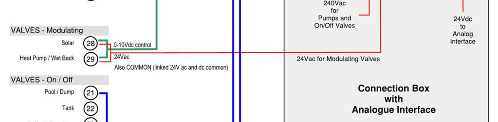
39 Please also refer to the Wiring Diagram (Appendix A2) at the end of this section for a view as to how the components relate together. Terminal group numbers are also shown on that page. Connection Box Terminal Block Connections and cables Most outputs are controlled by a relay which is located below these terminals with its purpose clearly marked. The relays have a red indicator light to show when the output should be operating. Input Power The 240V cables from the circuit breaker in the Power Box connect to the terminals marked "INPUT 240Vac". The 24V cables (both ac and dc supplies) from the Power Box connect to the two 2A fuses marked "INPUT 24V". Both fuses have a red indicator light which would normally turn on if the fuse has blown (provided power is available). These input power terminals do not have Terminal Numbers Heat Demand Sets of red and black terminals The red and black terminals connect to the respective thermostat and these thermostats MUST be powered only from the circuit breaker output in the Solamander Power Box. Terminals 1 Radiators Terminals 2 Hydronic Floor Heating (which is not part of the buffer zone) Terminals 3 (future spare) Boiler and Heat Pump Grey terminals in sets of two. These are the signals sent to advise when this heat source needs to be operating. These terminals connect to a normally open relay contact which closes when the heat source is to run. They are isolated from any power source and are not to be used to power that heat source. Terminals 8 Gas Boiler Terminals 9 Heat Pump Output to Pumps Sets of red and black terminals, where the red is active and the black is the common neutral supply These terminals supply 240Vac power directly to the pumps whenever they are required to run. Terminals 11 Solar pump Terminals 12 Wet Back pump Terminals 13 Hydronic Floor Heating pump supply (may be to multiple pumps and includes the pump that operates for the buffer floor heating zone) Output to Valves On/off control 38 P age
40 Sets of orange, red and black terminals, where the orange is the 240Vac supply that operates the valve when it is required, red is a permanent 240Vac active and black is the common neutral. When the orange terminal is at 240Vac then this valve operates to permit water to flow to that area for heating or to receive heat from a heat source. The PLC usually has a time delay from the operation of the valve to the activation of a heat source. Terminals 21 Pool or other Heat Dump Terminals 22 DHW Tank Terminals 23 Buffer Hydronic Floor Heating zone Terminals 24 Radiators Terminals 25 Gas Boiler Terminals 26 Heat Pump Output to Valves Analogue Sets of buff, brown and black terminals, where buff is the analogue signal (0-10Vdc)to the valve, brown is a permanent 24Vac power supply to the valve, and black is the common of the 24Vac and 24Vdc supplies (and is also common to the 240Vac neutral). These valves are Danfoss AB-QM pressure independent balancing valves and their actuators receive a variable 0 to 10Vdc signal from the controller to operate the valve a variable amount to permit the required flow of water from the heat source(s). Terminals 28 Solar valve Terminals 29 Wet Back or Heat Pump valve Input from Temperature Sensors Sets of white and grey terminals. The temperature sensor NTC Thermistors (15k ohm at 25 C) connect to these terminals. Each sensor usually has one black and one white conductor but they are not polarity sensitive. The supplied DEVI sensors must be use. The conductors from each sensor may be connected to either coloured terminal. The sensor cables may be extended with 1.5m² cable (usually figure-8 to signify that they are not normal 240V wiring). Maximum extension length is 50m. Terminals 41 to 48 Temperature Sensors BMS - Cables and Connections Sets of white terminals preceded with a black common +24Vdc terminal. If a BMS (Building Management System) needs to be integrated with Solamander or if there are other external inputs that are required then they would connect to the separate BMS terminal block in the Connection Box. If BMS mode is selected then all of the following functions are to be from an external source. The HMI Touch Screen settings for these functions are then inactive. When a contact or switch is closed between the common (terminal 90) and any of the terminals below then that function is enabled. The contact or switch must be isolated from all other power sources. This facility operates at 24Vdc and it is essential that no other power is applied to any of these terminals. A 0.5A fuse is incorporated in the common black terminal 90. Terminal 90* Common (+24Vdc) 39 P age

41 Terminal 91 Pool heating required Terminal 92 Radiator heating allowed Terminal 93 Winter Mode on Terminal 94* Buffer Floor Heating allowed Terminal 95* Energy Saving Mode enabled Terminal 96* Hydronic Floor Heating allowed * Terminals 90, 94, 95, 96 must be linked together if no BMS or external inputs are used. Diagram 17 BMS Connection Box This also shows the wire links that are required when the BMS link is not being used Balancing and Commissioning Hydronic Energy Hub Balancing and commissioning starts with ensuring all air is removed from the system. While this is a simple process it can be time consuming as it is imperative that all air is removed. Below is a guideline to remove air from the Solamander Hydronic Energy Hub. Fill the system with mains pressure first. It is important to flush out the entire system to remove any chemicals that may be left from when the products were manufactured. When filling the system for the first time it will take a long time for water to fill the entire system, especially if there is a large Floor Heating area. It may be necessary depending on what pressure the mains are in the area of the installation to boost the pressure using a small, high-pressure pump. This will help push the water through and the air out. You can connect the mains pressure through the hub for the initial system fill. It will be most time effective if you isolate each section and remove air from one station at a time. For example you can feed water through the manifold and remove all the air from the circuits in the floor. Once this is complete shut off this station and focus on another station. The simple way to ensure all air is removed is to use a submersible pump. Leave the pump in a container filled with water and pump water into the system. Have the return water feed back into the container filled with water via a hose left below the water level. As the return water flows back into the container it will push air out and you can monitor this by watching for air bubbles. Hydronic Floor Heating 40 P age
42 This is a time consuming process and time should be allowed to complete this properly. Once air is removed the system should be left at 2.5 bar. The Hydronic Floor Heating will need to be balanced once the system is running to ensure that even heat is distributed across the floor. This is crucial to ensure that you get an even heat. This process is straight forward, particularly if you have all of the circuits close to the same length. The boiler will also need to be commissioned. For boiler commissioning refer to the boiler instruction manual as each model of boiler has specific requirements. It is best to complete the balancing of the system after you commission the boiler. It is also preferable that the boiler has been running for at least an hour to allow the return lines to have some heat. Please note you may need to do a slight adjustment once the slab has reached temperature, this is generally due to the pipe being at different depths in the slab or the slab having cold spots. 1. Complete the job detail in the Manifold Balancing Report. (See Appendix A3 below). You will also need to record the circuit lengths and current settings of each circuit. The circuit information will assist you to adjust each circuit. 2. Record the time then using your infra-red temperature sensing gun record the supply and return temperature. 3. From left to right measure and record the temperature of each circuit on the return side of the manifold. 4. Review your findings. If you have a difference between circuits you will need to make adjustments. For example if all of your circuits are set on N (which is recommended for your first reading) and you have four circuits and one circuit is five cooler than the other circuits you could turn the other four circuits down to 7 which is the second highest setting. This process will allow less flow through these circuits therefore more flow through the cooler circuit. 5. Record you adjustments on the Manifold Balancing Report 6. Wait a minimum of five minutes for the system to rebalance 7. Repeat the process again. Measure each circuit from left to right and record your finding. You will find that the temperatures have changed according to your adjustments. 8. Continue this process until you get all circuits recording the same temperature. Your allowance for difference across each circuit should be no more than one C. 41 P age


43 5 Controller Operation and Settings 5.1 Navigation: For Home Owner & Installer Use. The navigation of the controller uses a touch screen Human Machine Interface (HMI). There are some key navigation buttons that are important for you to familiarise yourself with when you first switch on the controller. Home Screen: This is the Main Menu or Home Screen that will provide a starting point for programming your controller. Complete with six menu items, simply touch the appropriate button to go a particular area on the controller and continue to follow the prompts i.e. touch MODES to go to the Modes section. 5.2 Key Functions: Example screen below Touch HOME to go to the Home Screen. Touch HELP on any screen get a more detailed description on that area. Touch the UP or DOWN arrow (top/bottom right corner) on any screen to scroll through a section that has multiple pages. Touch BACK arrow (top left corner) on any screen to go back to the previous screen. 42 P age


44 5.3 Changing Settings: Example screen below Press the button to change the setting to ON/OFF Setting is ON when green Setting is OFF when grey 5.4 Entering Values Example screen below Only values in a white box can be changed by the user/installer. To change the value, touch the white box and use the input keys that will appear on the screen to enter the new value. If the value is out of the allowable range of values, an Error Message will appear. 5.5 Outputs: This shows the Output status as either ON or OFF at any given time. For example, when an Output to a Pump or Valve is ON, the icon will read ON and have a green background. Similarly, the icon will read OFF and change to a grey background when the Output is no longer running. 43 P age
45 5.6 Modes: For Home Owner & Installer use. The Modes section enables the user to change the operation of the system. It must be configured for Mode Select from HMI to allow these changes, otherwise these changes are required to be made remotely. Mode Winter Mode Allow Buffer Floor Heating Energy Savings Run Pool Heating Description Allows floor heating and radiator heating to operate when ON (where installed). Normally OFF during summer. Allows the allocated buffer floor heating zone to operate (if it has been configured). This may be set to LOW or HIGH. This only applies to the buffer floor heating. LOW Provides temperature control which is closer to the comfort setting selected for the Buffer Floor Heating. HI Allows a wider swing in temperature for greater economy and energy saving. The amount of swing is determined by the set Difference Energy Savings. Reference the appropriate parameter SC12 for further details (Appendix A1). Turns pool heating ON. The user can use the auxiliary heat source to heat the pool. Note, the heating will continue until the user changes the Run Pool Heating mode back to OFF. 44 P age
46 5.7 View: For Home Owner & Installer use. Allows the user to View how the system is currently running. It shows key details like Input Temperatures and Output Signals. Selection Overview Display temperature measurements and outputs that are running. Heat Sources Display for each heat source (e.g. Solar, Wet Back, Heat Pump, Gas Boiler) Heat Storage Display for each heat storage (e.g. Domestic Hot Water, Buffer Floor). Heat Uses Display each energy use (e.g. Radiators, Hydronic Floor, Pool). Sub-Selection Description Temperatures Outputs Display temperature measurements for Heat Sources, Uses and Storage. Display which Outputs are running for energy sources and energy uses. Energy Source 1 Displays key settings, inputs and/or outputs for Energy Source 1. Energy Source 2 Displays key settings, inputs and/or outputs for Energy Source 2. Energy Source 3 Displays key settings, inputs and/or outputs for Energy Source 3. DHW Displays DHW operation (incl. Buffer tank, reserve temp etc.) Buffer Floor Heating Displays the floor heating operation in the buffer heating storage zone (incl. ON/OFF function, set temp, energy savings etc.) Energy Use 1 Displays key settings for Energy Use 1. Energy Use 2 Displays key settings for Energy Use 2. Energy Use 3 Displays key settings for Energy Use P age
47 5.8 Settings: For Installer Use Only. Enables the installer to change key settings in the system at each station, depending on the way each particular station is configured, i.e. Station 1 is Solar, while Station 2 could be a Wet Back or Heat Pump. See Configuration section below for further details. Selection Description Station 1 Change any setting relating to Station 1. Station 2 Change any setting relating to Station 2. Station 3 Change any setting relating to Station 3. Station 4 Change any setting relating to the DHW Station. Station 5 Change any setting relating to the Radiator Station. Station 6 Change any setting relating to the Hydronic Floor Heating setting. Station 7 Change any setting relating to the Pool (Dump) setting. Please note the ALL PARAMETERS button gives you access to all system settings and parameters which can be used rather than going through the All Parameters menu buttons directly. Note, the controller allows you to change a setting in many different screens. See table in Appendix A-A1 Parameters All Parameters section. 46 P age
48 5.9 Configuration: For Installer Use Only. Allows the installer to configure each of the stations. Selection Configuration Description Station 1 n/a Always assumed to be solar. Station 2 Wet Back Select Turn ON to configure that a Wet Back has been installed on Station 2. Heat Pump Select Turn ON to configure that a Heat Pump has been installed on Station 2. Only one heat source can be selected. Heat Pump Priority O-Ride The Heat Pump normally has priority as the non-renewable heat source. Turn ON this override if the Gas Boiler is to run as priority over the Heat Pump. (SC3P) Station 3 Gas Boiler Turn ON to configure that a Gas Boiler has been installed on Station 3. Heat Pump Turn ON to configure that a Heat Pump has been installed on Station 3. Only one heat source can be selected. Station 5 & 6 Radiator Heating Turn ON to configure that Radiator(s) have been installed on Station 5. Hydronic Floor Heating Turn ON to configure that Hydronic Floor Heating has been installed on Station 6. Buffer Floor Heating Buffer Floor Heating Turn ON to configure that the Hydronic Buffer Floor Heating zone is included on Station 6. Station 7 Pool Heater Turn ON to configure that Pool Heating has been installed on Station 7. Data Collection Data Collection Interval (mins) Manages the regular automatic collection of temperatures and system operation. Save Data to USB Save Status Mode Switching Mode Selection Source Allows inputs from HMI touchscreen (such Modes from HMI Modes from Inputs as a BMS) or remote inputs to the system. Factory Defaults Load Factory Settings Use to set Factory Default settings. 47 P age

49 5.10 Set Time: Update the system s date and time as required. Select the field to be changed and use the numeric keypad that will appear on the screen to enter the desired value Version Info: Shows the software version currently running on the system, this can change when/if system updates occur Uploading Software: When the HMI Controller and the Power Box are wired to the Connection Box with 240V power connected to the Power Box and all is ready to run (the valves, pumps and temperature sensors do not need to be connected at this stage). Insert the USB memory disc stick into the controller USB port (the controller must not be powered up). The USB must have the program files loaded in the root directory. Turn on the circuit breaker in the Power Box The controller will immediately recognise the program change and will load it into the controller. When completed, remove the USB memory disc, otherwise if there is a power failure it may re-load the program and wipe any local configuration and settings Link to a Network This permits the controller to be accessed through the internet via your local network. Go to the controller setup functions screen (touch diagonal corners sequentially on the screen until the blue controller screen appears), displaying the following tabs Offline, System, Diagnosis. 48 P age
50 If this is the first time to access the controller setup functions, then Initial Start Mode may be displayed. Touch the Network Icon (the top right button). Language selection should be "English". Select Offline tab screen, then the Network button. If the controller is running, this will stop the controller and re-boot in setup mode to display the Static IP addresses. Enter the IP addresses assigned by your network administrator for the controller to operate through. The values below are the defaults for a new controller which has not been set up. IP Address Subnet Mask Default Gateway All three addresses are required from your administrator. Re-boot the controller to return to normal operation by touching the To Run Mode button at the bottom right of the screen Troubleshooting Controller: NORMAL OPERATION Trouble Power Box Controller Box HMI Controller Box Solution Green LED light ON means 24Vdc is available to the controller. Analogue Interface Unit (OTB) - Green "PWR" light ON - Green "Run" light ON - Red "ËRR" light OFF Temperature Sensor Unit - Green "Power" light ON. Fuse lights (red) must be OFF - supplies 24Vdc and 24Vac to the controller and valves. CAN light (back of controller) - Green steady ON CAN communication is active - Green with twin orange flashes CAN cable not connecting between the HMI and the Connection Box. 49 P age
51 OPERATION CONCERNS ERROR LIGHTS / MESSAGES HMI screen is blank with no backlighting Program not running e.g. temperatures not being displayed or not changing Connection Box (OTB Analogue Interface Unit) HMI Controller Touch screen to activate Check that power is on - power being supplied to the Power Box - circuit breaker in Power Box switched on - fuses in Control Box ok (24Vdc 2.0A) CAN Bus cable not connecting between HMI Controller and the Connection Box. Red "ERR" light ON - CAN Bus cable not connecting to the HMI Controller - Program stopped due to error Various errors and messages appear (white on black) on the screen. These can be information on changes made or errors which are usually self-explanatory. Messages of concern should be written down and reported. 50 P age
52 6 Troubleshooting There are often simple solutions to issues that may arise during installation, commissioning or servicing of a Solamander Hydronic Energy Hub system. Below is a list of problem solving techniques for the easy to solve issues that can arise if installation is not completed correctly. Please contact Devex Systems Service Department if the issue cannot be resolved onsite. 6.1 Air in the system This issue can arise if all air was not completely removed during commissioning. It can result in the boiler shutting off and the system losing pressure. It is simple to diagnose, simply check one of the pressure gauges located on the hub or at the boiler. To rectify this issue please refer back to section 4.13 and repeat the process. It can also help to bleed the air at the highest point which is usually at the solar panels. 6.2 Uneven heat across the floor This is common if balancing was not completed correctly or was completed before the slab had reached its desired temperature. Again, refer to section 4.13 and simply rebalance the system at the manifolds. 6.3 Boiler not distributing heat or short cycling Ensure that the boiler has been commissioned correctly. Refer to the boiler manual and ensure all the commissioning requirements have been met. If unsure contact Devex Systems Service Department or the boiler manufacturer. See also 5.14 Troubleshooting Controller 51 P age
53 7 Warranties The following warranties are for each of the individual components of the Solamander Hydronic Energy Hub and controller. The remaining support components are dependent on the brand and manufacturer you choose to move forward with. The Hydronic Energy Hub: Danfoss valves and actuators: 2 year warranty Copper pipes: 25 year warranty All other components: 1 year warranty Controller: Schneider controller: 1 year warranty Support Components: Energy Uses Immergas domestic hot water tanks: 25 year warranty De Longhi radiators: 25 Year Manufactures Guarantee Danfoss thermostatic sensors, manifolds, valves & controls: 2 year warranty Titanium plate heat exchangers: 2 year warranty Support Components: Energy Sources Thermann solar tubes: 15 year warranty Bosch gas boilers: 1 year warranty Baxi gas boilers: 2 year warranty Grundfos pumps: 2 year warranty 52 P age
54 8 Appendix A Reference Tables and Figures A1 Parameters For Installer Use Only. Select this to scroll through a complete list of all of system parameters. The following table describes each of these parameters in more detail: Parameter Name Description CONFIGURATION SC1 Pool Heat Exchanger Turn ON if Pool heating is installed and is to be permitted. SC2 Wet Back Select Turn ON if a Wet Back heater is installed. SC3 Heat Pump Select Turn ON if a Heat Pump is installed. SC3P Heat Pump Priority O-Ride The Heat Pump normally has priority as the non-renewable heat source. Turn ON this override if the Gas Boiler is to run as priority over the Heat Pump. SC5 Gas Boiler Turn ON if a Gas Boiler is installed. SC5 Auxiliary Priority Set to "3" if a Heat Pump is configured but the Gas Boiler is to be the priority Auxiliary heat source to be run first. Normal priority is with this set to "2". SC6 Radiator Heat Configured Turn ON if Radiators have been installed on Station 5. SC7 Buffer Floor Heating Turn ON to configure that a Hydronic Buffer Floor Heating zone is included on Station 6. SC8 Hydronic Floor heating Turn ON if any Hydronic Floor Heating has been installed on Station 6. SC9 Mode Select from HMI Only allow mode inputs from this HMI touch screen. SC10 HMI Winter Mode Allows floor heating and radiators to operate when ON (where installed). Normally OFF during summer. Allows the allocated buffer floor heating zone to operate. SC11 HMI Allow Buffer Floor Heating SC12 Energy Savings This may be set to LOW or HIGH. SC13 Run Pool Heating n/a DOMESTIC HOT WATER SD1 Buffer Tank Min Temp The minimum temperature that the DHW (Domestic Hot Water) tank is permitted to drop to before a non-renewable heat source is called in for heating. This is the minimum hot water heat buffer. 53 P age
55 SD2 Buffer Tank Reserve Temp The minimum temperature that the DHW tank will be heated to as a het buffer with a non-renewable heat source. SD3 Buffer Tank Max Temp The maximum temperature that the DHW tank is permitted to be heated to. Note that this limit cannot be higher than the renewable heat source(s) ability. SD4 Tank Set Temp Hysteresis The hysteresis value used for the DHW buffer tank settings. SD5 SD6 Buffer Tank Minimum Exposure Temp Buffer Tank Minimum Exposure Time (mins) Used for Legionella control. The tank must be maintained at least at this temperature to control Legionella. Used for Legionella control. The tank must be maintained for at least at this time (in seconds) to control Legionella. SD7 Check Period (days) Used for Legionella control. The tank must exceed the exposure temperature for the time period within this number of days or the Legionella function will be run using a non-renewable heat source. SD8 Day Counter Used for Legionella control. The number of days since the Legionella control was satisfied. This is counted automatically and does not have to be set. SD9 Minute Counter Used for Legionella control. The number of minutes that the Legionella control function has been running. This is counted automatically and does not have to be set. SD10 Legionella Test Time The time of day (hh:mm) when a check is done to determine if Legionella control is to be run. Usually end of day for Solar only systems. SD11 SD12 SD13 SD14 Buffer Tank Minimum Temperature Limit Buffer Tank Reserve Maximum Temp Limit Set Back Temp vs Heat Pump Supply Temp Set Back Temp vs Heat Pump Reserve Supply Temp The maximum temperature that the DHW tank minimum temperature setting may be set to. This must not be higher than the maximum rated supply temperature capability of the Heat Pump (where one is configured). The maximum temperature that the DHW tank maximum temperature setting may be set to. This must not be higher than the maximum rated supply temperature capability of the Heat Pump (where one is configured). The setback used to reduce the tank minimum temperature allowed. Only used for Heat Pumps. The setback used to reduce the tank reserve temperature allowed. Only used for Heat Pumps. 54 P age
56 FLOOR HEATING SF1 Buffer Max Temp The maximum temperature that the Buffer Floor area is permitted to be heated to. This is automatically set from the Comfort setting and Energy Saving mode. SF2 Buffer Floor Comfort Temp The desired comfort temperature of the Buffer Floor area heating. SF3 Buffer Floor Aux Max Temp The maximum temperature allowed for the Buffer Floor area heating. This is automatically set from the Comfort setting and Energy Saving mode. SF4 Buffer Floor Aux Min Temp The minimum temperature allowed for the Buffer Floor area heating. This is automatically set from the Comfort setting and Energy Saving mode. SF5 Difference Energy Savings The set temperature difference permitted when Energy Saving mode is ON. This is used to adjust the Min and Max temperatures permitted for the Buffer floor area only. HUB LOOP SL1 Maximum Return Temp Dump of excess heat will occur when the Hub loop return temperature reaches this set temperature. This is a safety function. GAS BOILER SG1 Gas Boiler Set Temp The running temperature, as set on the boiler's dial. (not used) SG2 Gas Boiler Tolerance Tolerance setting (a few degrees) for the set gas boiler operating temperature. SG3 Gas Boiler Delta T Max Maximum temperature difference from the priority heat source (when this is the Gas Boiler) to the non-priority heat source. SG4 Gas Boiler Delay (secs) Time delay (in seconds) before Gas Boiler will start to run after the conditions are reached that call for the Gas Boiler's operation. SG5 HEAT PUMP SH1 Gas Boiler Minimum Run Time (secs) Time (in seconds) Gas Boiler will run for once is has started to run. Heat Pump Supply Target Temp SH2 Heat Pump Proportional Gain SH3 Heat Pump Integral Gain (Technician use only) Flow control Integral setting Desired temperature to be maintained by the Heat Pump. (Technician use only) Flow control Proportional setting 55 P age
57 SH4 Heat Pump PID Controller Wait Time (sec) (Technician use only) Flow control Wait time setting in seconds. SH5 Heat Pump Delay (secs) Time delay (in seconds) before Heat Pump will run after Heat Pump has been called to operate. SH6 Minimum Heat Pump Run Time (secs) Time pump will run after the demand for the Heat Pump has been satisfied. SH7 Heat Pump Differential Gain K Flow control Differential setting for the PID control function. SH8 Heat Pump Min Out Limit n/a SH9 Heat Pump Max Out Limit n/a SOLAR SS1 Target Solar Temp Desired temperature to be maintained at the solar panel SS2 Solar Delta Temp Minimum Temperature difference required between the solar panel and the energy hub before the solar pump will run to capture solar energy. SS3 Max Solar Set Temp Heat to be dumped when this temperature is reached SS4 Solar Set T Hysteresis Temperature hysteresis setting for solar panel SS5 Solar Pump Delay Time delay (in seconds) before solar pump will run after solar panel reaches set target temperature. SS6 Solar PID Control Wait (Technician use only) Flow control Wait time setting. SS7 Solar Prop Gain K (Technician use only) Flow control Proportional setting SS8 Solar Integral Gain K (Technician use only) Flow control Integral setting SS9 Solar Pump Min Run Time Time pump will run after solar panel drops below set target temperature SS10 Solar Differential Gain K Flow control Differential setting for the PID control function. SS11 Solar Min Out Limit n/a SS12 Solar Max Out limit n/a WET BACK SW1 Target Wet Back Temp Desired temperature to be maintained at the Wet Back SW2 Wet Back Delta Temp Set Minimum Temperature difference required between the Wet Back and the energy hub before the Wet Back pump will run to capture Wet Back energy. SW3 Wet Back Set Temp Hysteresis Temperature hysteresis setting for Wet Back. 56 P age
58 SW4 Wet Back Prop Gain K (Technician use only) Flow control Proportional setting. SW5 Wet Back Integral Gain (Technician use only) Flow control Integral setting SW6 Wet Back PID Control Wait Time (Technician use only) Flow control Wait Time setting in seconds. SW7 Max Wet Back Temp Heat to be dumped when this temperature is reached SW8 Wet Back Run Delay Time delay (in seconds) before Wet Back pump will run after Wet Back reaches set target temperature. SW9 Wet Back Min Run Time Time pump will run (in seconds) after Wet Back SW10 drops below set target temperature Wet Back Differential Gain K Flow control Differential setting for the PID control function. SW11 Wet Back Min Out Limit n/a SW12 Wet Back Max Out Limit n/a 57 P age


59 A2 Wiring Diagram 58 P age
Pivot Stove Hydronic Installation Guide
 Pivot Stove Hydronic Installation Guide Install Location When installing the header tank - install directly above the appliance. There needs to be a continual rise between the appliance and the header
EFG ENERGY OPTIMISING SYSTEMS
 EFG ENERGY OPTIMISING SYSTEMS High-performance energy control systems for maximum performance from solar collectors and other renewable and non-renewable heat sources Maximum comfort, minimum energy costs
Heat Transfer Products, Inc. 120 Braley Road East Freetown, MA The first totally integrated multiple boiler management control.
 Heat Transfer Products, Inc. 120 Braley Road East Freetown, MA 02717 The first totally integrated multiple boiler management control. USING THIS MANUAL USING THIS MANUAL A. INSTALLATION SEQUENCE Follow
heat interface units A BOILER WITHOUT A FLAME
 A BOILER WITHOUT A FLAME heat interface units Communal Heat Networks A central boiler house will generate heat which is distributed through a network of pipe to each home or apartment in the building.
prestige Control Application Supplement - TriMax
 prestige Control Application Supplement - TriMax L I S T E D WARNING This document is intended to be used by a factory trained and qualified heating contractor or service technician only. Read all instructions
prestige Control Application Supplement - TriMax
 prestige Control Application Supplement - TriMax L I S T E D WARNING This document is intended to be used by a factory trained and qualified heating contractor or service technician only. Read all instructions
... Green Building Details
 Combining Solar HW with Radiant Floor using a Demand Water Heater back-up and a Tempering Tank with a line voltage three-way valve to prevent heating the solar storage with the gas DHW... A short list
- Data Brochure Universal Reset Module 422
 - Data Brochure Universal Reset Module 422 D 422 08/07 1 Information Brochure Choose controls to match application Application Brochure Design your mechanical applications 2 3 Rough-in Wiring Rough-in
Operating Guide. Termix Compact 28 VX-FI / HWP / HWS. 1.0 Table of Contents. 1.0 Table of Contents
 1.0 Table of Contents 1.0 Table of Contents... 1........................................................................ 2 2.0 Functional description... 3 3.0 Safety notes... 4 3.1 Safety Notes general............................................
Operating Guide. Termix Solar A+/B+ 1.0 Table of Contents. 1.0 Table of Contents
 1.0 Table of Contents 1.0 Table of Contents... 1........................................................................ 2 2.0 Functional description... 3 3.0 Safety notes... 4 3.1 Safety Notes general............................................
Outdoor Reset Control Theory FULL versus PARTIAL reset
 Outdoor Reset Control Theory FULL versus PARTIAL reset Conventional boilers must be protected against sustained operation at low temperatures. If not, they will be damaged by sustained flue gas condensation.
prestige Control Application Supplement - ACVMax
 2015-10 Prestige ACVMax Control Sup 12-14-15_ACVMax_Control 12/15/15 7:36 AM Page 1 prestige Control Application Supplement - ACVMax L I S T E D WARNING This document is intended to be used by a factory
Control Application. Supplement - ACVMax
 prestige Control Application Supplement - ACVMax L I S T E D WARNING This document is intended to be used by a factory trained and qualified heating contractor or service technician only. Read all instructions
TABLE OF CONTENTS TECHNICAL DOCUMENTATION 03. Technical Data Electrical Details Connection Details Dimensions Standing Losses
 INSPIRED H I G H H O T EF F ICIENCY E F F I C I E N C Y W A T E R S Y S T E M S E XT REME HIGH EFFICIENCY HO T W AT ER SY ST EMS w i th I N JECT I O N DYN A M I C S T ECHN I CAL DO CUME N TA T I O N I
VIESMANN. Installation instructions VITOCELL 300-B. for contractors. Vitocell 300-B Type EVBA-A. Dual mode DHW cylinder, 300 and 500 l
 Installation instructions for contractors VIESMANN Vitocell 300-B Type EVBA-A Dual mode DHW cylinder, 300 and 500 l VITOCELL 300-B 1/2017 Dispose after installation. Safety instructions Please follow these
INSTALLATION INSTRUCTIONS FOR MODELS 16NG50-6/16LP50-6, 16NG60-6/16LP60-6, 20NG50-6/20LP50-6, 20NG60-6/20LP60-6, 26NG50-6/26LP50-6, 26NG60-6/26LP60-6
 GAS CONTINUOUS FLOW WATER HEATERS INSTALLATION INSTRUCTIONS FOR MODELS 16NG50-6/16LP50-6, 16NG60-6/16LP60-6, 20NG50-6/20LP50-6, 20NG60-6/20LP60-6, 26NG50-6/26LP50-6, 26NG60-6/26LP60-6 2 INSTALLATION INSTRUCTIONS
EVACUATED TUBE SOLAR HOT WATER SYSTEMS OWNERS MANUAL JULY 2013 BROCMISC100.1
 EVACUATED TUBE SOLAR HOT WATER SYSTEMS OWNERS MANUAL JULY 2013 BROCMISC100.1 Thermann Solar Hot Water System - Owners Manual Thank You Thank you for purchasing a Thermann solar hot water system. Please
SEALED THERMAL STORE
 ISSUE 3 0717 INSTALLATION AND USER GUIDE ENERGYMANAGER SEALED THERMAL STORE ADVANCE APPLIANCES LTD PLEASE RETAIN AND ENSURE SERVICE RECORDS ARE KEPT UP TO DATE. SCHEMATIC DIAGRAM OF ENERYMANAGER THERMAL
B-40/B-41 Modulating Temperature Controller
 INSTALLATION & OPERATING INSTRUCTIONS B-40/B-41 Modulating Temperature Controller For Raytherm Boilers & Water Heaters H2 514-4001 WH2 2100-4001 Catalog No. 5000.70 Effective: 12-21-11 Replaces: NEW P/N
80HMA. Comfort Module Range for Monobloc Heat Pumps. Nominal heating capacity 4-20 kw Nominal cooling capacity 4-20 kw. Features
 Comfort Module Range for Monobloc Heat Pumps Quality Management Systems Comfort module with two-zone kit Single-zone comfort module 8HMA Nominal heating capacity 4- kw Nominal cooling capacity 4- kw The
80HMA. Comfort Module Range for Monobloc Heat Pumps. Compact comfort module. DHW management possibility. Multi zone option control.
 product selection data Compact comfort module DHW management possibility Multi zone option control Easy installation Comfort module with two-zone kit Single-zone comfort module Comfort Module Range for
INSTALLATION/OPERATING INSTRUCTIONS BCP-3. Hot Water Reset Control For up to 3 Boilers. How the BCP-3 operates... 1:4 1:3 1:2 1:1.
 INSTALLATION/OPERATING INSTRUCTIONS BCP-3 Hot Water Reset Control For up to 3 Boilers The BCP-3 establishes ambient comfort by varying the temperature of the heating system's circulating hot water in response
Atmos EasySolar. Installation Instructions for. Sloping roof and flat roof installation with evacuated tube collector
 Atmos EasySolar Installation Instructions for Atmos EasySolar Sloping roof and flat roof installation with evacuated tube collector Atmos Heating Systems TBS Building Supplies Ltd Hackwood Road Daventry
ADVANCE ECB ELECTRIC COMBINATION BOILER
 ISSUE ISSUE 45 0115 0317 INSTALLATION AND USER GUIDE ADVANCE ECB ELECTRIC COMBINATION BOILER ADVANCE APPLIANCES LTD HOUSEHOLDER - PLEASE RETAIN AND ENSURE SERVICE RECORDS ARE KEPT UP TO DATE 1 SCHEMATIC
MULTI-TEMPERATURE LOOP CONTROL BOARD INSTRUCTIONS
 LCB-I-O Rev B MULTI-TEMPERATURE LOOP CONTROL BOARD INSTRUCTIONS Models: KB 81-286, KBXL 400-801, WB 51-211, and WH 55-399 IMG00116 WARNING This manual must only be used by a qualified heating installer
Sundance Spas SPA EQUIPMENT SYSTEM. Installation Instructions. P/N Rev. A
 Sundance Spas SPA EQUIPMENT SYSTEM Installation Instructions P/N 6530-456 Rev. A Contents Important Notices 1 Important Safety Instructions 2 Where to Place the Equipment System 3 Connecting Pipes Between
Installation, Operation and Maintenance Instructions for PlantPac Steam Plate Heat Exchanger Package
 OM014 Installation, Operation and Maintenance Instructions for PlantPac Steam Plate Heat Exchanger Package The operating and maintenance instructions contained within this package are for PlantPac packaged
Installation, Operating, and Maintenance Manual
 www.geo-flo.com Engineered Solutions Making Geothermal Easier Installation, Operating, and Maintenance Manual Part # 3619 Rev. 27APR2017 Geo-Booster Geo-Flo Products Corporation 905 Williams Park Drive
General System Layout Sketch
 General System Layout Sketch EZ-37 Solar Panels PV panel Glycol Fill Valve Expansion Tank ` 1 Introduction This document describes how to install a Heliatos GH type solar water heating system. These systems
Hydronic & HVAC Control Systems
 tekmar 218 Full Line Catalog Hydronic & HVAC Control Systems HVAC Multi-Staging Alternative Energy Zoning Snow Melting Setpoint tekmarcontrols.com tekmarcontrols.com Better Design, Better Control, Better
TWINTEMP JR. HYDRONIC SYSTEM 2/2013
 TWINTEMP JR. HYDRONIC SYSTEM 2/2013 TwinTemp Description of Operation and Sequence of Operation Technical Description of Operation The TwinTemp systems provide quiet space heating utilizing liquid to air
PLEASE LEAVE THIS MANUAL WITH THE OSO UNIT AFTER INSTALLATION INSTALLATION MANUAL
 PLEASE LEAVE THIS MANUAL WITH THE OSO UNIT AFTER INSTALLATION SOLARCYL IM/SC INSTALLATION MANUAL This manual gives detailed advice for installation and should be read carefully prior to fitting any unvented
CALEFFI. SATK wall-mounted heat interface unit Fitted for connection to DHW storage. SATK40 series 01216/14 GB
 4 RESET ON DHW CH FAULT SATK wall-mounted heat interface unit Fitted for connection to DHW storage SATK4 series ACCREDITED CALEFFI 6/4 GB ISO 9 FM 64 ISO 9 No. The latest generation of heat interface units
UPONOR Ltd. Specification for UPONOR Q&E PEX Shrinkfit Plumbing Systems
 UPONOR Ltd Specification for UPONOR Q&E PEX Shrinkfit Plumbing Systems Reference Page(s) UPONOR Q&E PEX 2 Operating Conditions 2 Pipe Properties 2 Fittings Range 3 Radiator Heating Systems 3 H&C Water
OPERATING AND MAINTENANCE MANUAL FOR PLATE HEAT EXCHANGER INDIRECT FIRED WATER HEATER. Electric Heater Company Base Model "BWXP"
 OPERATING AND MAINTENANCE MANUAL FOR PLATE HEAT EXCHANGER INDIRECT FIRED WATER HEATER Electric Heater Company Base Model "BWXP" HUBBELL ELECTRIC HEATER COMPANY P.O. BOX 288 STRATFORD, CT 06615 PHONE: (203)
Atmos EasySolar. Installation Instructions for. In-roof and flat roof installation with flat plate collectors
 Atmos EasySolar Installation Instructions for Atmos EasySolar In-roof and flat roof installation with flat plate collectors Atmos Heating Systems West March Daventry Northants, NN11 4SA Tel: 01327 871990
All Valve Industries. General Product Overview. Distributed by All Valve Industries. Ph: Fax:
 All Valve Industries General Product Overview Distributed by All Valve Industries Ph: +61 2 8543 5111 Fax: +61 2 8543 5122 www.allvalve.com.au Manufacturer Introduction All Valve Industries has aligned
Installer s Guide IMPORTANT INFORMATION Read This Document First On completion, sign and leave with owner
 IMPORTANT INFORMATION Read This Document First On completion, sign and leave with owner Pre Boosted Gas Solar Water Heater MP15 Models: DN15DS DL15DS DN15CS DL15CS Installation only by a licensed tradesperson
INSTALLATION INSTRUCTIONS ONE LARGE ZONE
 INSTALLATION INSTRUCTIONS ONE LARGE ZONE Unit 1 79 Friar Street Worcester WR1 2NT Tel: 01905 354 791 Fax: 01905 352 100 E-mail: info@underfloorheatingsystems.co.uk Website: www.underfloorheatingsystems.co.uk
MULTI-TEMPERATURE LOOP CONTROL BOARD INSTRUCTIONS
 LCB-I-O Rev D MULTI-TEMPERATURE LOOP CONTROL BOARD INSTRUCTIONS Models: KB 81-286, KBXL 400-801, WB 51-211, FTX 400-850 and WH 55-399 WARNING This manual must only be used by a qualified heating installer
UNIQ HEAT BATTERIES REFERENCE MANUAL_V2.2. Version: 2018_07_19_v2.2
 UNIQ HEAT BATTERIES REFERENCE MANUAL_V2.2 Version: 2018_07_19_v2.2 Abstract This is a quick reference guide for selecting the UniQ range of heat batteries for the required application. For designing a
NAVIEN AMERICA INC FITCH AVENUE IRVINE, CALIFORNIA, USA
 Navien America Inc. Specification Details for the Navien models: CR-210 CR-210A For Indoor Installation Only For Potable Water Heating and Space Heating NAVIEN AMERICA INC. 17855 FITCH AVENUE IRVINE, CALIFORNIA,
Better Design, Better Control, Better Systems.
 Product Catalog Better Design, Better Control, Better Systems. At tekmar Control Systems, we believe the indoor comfort of a building depends on the performance of its heating, ventilating & air conditioning
IMAGINATION SOLAR LTD. Installation Guide B1. Planning the Plumbing and Wiring
 Page 1 of 8 IMAGINATION SOLAR LTD Installation Guide B1 Planning the Plumbing and Wiring Unit 4 Montpelier Central, Station Road Bristol BS6 5EE t: 0117 942 6668 f: 0117 942 8998 e: enquiries@imaginationsolar.com
Bosch. Gas Condensing Boiler. Applications Manual. 100, 151 Combi Boiler 57, 100, 131, 151 Heating Boiler
 WARNING: Improper installation, setup, modification, operation or maintenance of the heating system can cause personal injury and property damage. Follow each appliances' instructions precisely. For assistance
CAH SERIES INSTALLATION & MAINTENANCE MODELS CAH CAH
 CAH SERIES INSTALLATION & MAINTENANCE MODELS CAH 33-44-50 CAH 49-54-70 CAH VARIABLE SPEED AIR HANDLERS DIMENSIONS... 3 TECHNICAL SPECS... 4 INSTALLATION DON TS... 5 INSTALLATION DO S... 6 FREEZE STAT REQUIRED
Installation Information User Manual
 1-5 Anzac Avenue Smeaton Grange NSW 2567 is a division of BioSeptic Pty Ltd - ABN 95 056 461 226 Ph: 02 4629 6633 Fax: 02 4629 6677 Email: sales@sydneywatertanks.com.au Web: www.sydneywatertanks.com.au
Do you want a versatile solution
 Do you want a versatile solution to make significant savings? ESTIA TOSHIBA AIR CONDITIONING RESIDENTIAL HEATING AIR-TO-WATER HEAT PUMP ESTIA hatever you need ESTIA TO MAKE SIGNIFICANT SAVINGS Toshiba
INSTALLATION INSTRUCTIONS SINGLE CIRCUIT
 INSTALLATION INSTRUCTIONS SINGLE CIRCUIT Unit 1 79 Friar Street Worcester WR1 2NT Tel: 01905 616 928 Fax:01905 611 240 E-mail: info@underfloorheatingsystems.co.uk Website: www.underfloorheatingsystems.co.uk
SOLAR HEATING SYSTEMS
 introducing SOLAR HEATING SYSTEMS TM the low carbon water heating system June 2008 Irl 1 In this environmentally challenging world, it s time to rethink our heating.....while we still have time. There
Technical description. Atec.
 www.thermia.com Thermia Värmepumpar is not liable or bound by warranty if these instructions are not adhered to during installation or service. The English language is used for the original instructions.
Hydronic Mechanical Panels
 Hydronic Assemblies Inc. 56 Horse Hill Rd Concord NH 2015-2016 Hydronic Mechanical Panels Contact 4805 Main St. Waitsfield, Vermont 05673 Phone : 802-583-5500 WWW.Houseneeds.com Hydronic Assemblies Inc.
ECONOPLATE H1-heat only HEAT INTERFACE UNIT. Installation, Commissioning and Servicing Instructions for unvented systems.
 ECONOPLATE H1-heat only HEAT INTERFACE UNIT Installation, Commissioning and Servicing Instructions for unvented systems. Note: THESE INSTRUCTIONS MUST BE READ AND UNDERSTOOD BEFORE INSTALLING, COMMISSIONING,
LZT High efficiency air to water heat pumps with E.V.I. compressors
 High efficiency air to water heat pumps with E.V.I. compressors -20 C +43 C +65 C E.V.I. C.O.P. 4,1 The series of high efficiency heat pumps has been specifically designed for use with radiant floor heating
Efficient heating that won t cost the earth
 Product Range Guide Efficient heating that won t cost the earth CTC is an international manufacturer of innovative renewable heating solutions. For over 90 years our ranges of high performance products
SmartRad Planning Manual
 SmartRad Planning Manual Issue 1 15 April 2010 Dimplex SmartRad Fan Convector Models SRX80, SRX120, SRX140 & SRX180 Applies to models with White Glass, Black Glass and Metal facias Contents 1 Introduction
Hot Water Energy Storage THE HOT WATER PEOPLE HEAT INTERFACE UNIT ENGINEERED FOR ULTIMATE HEATING COMFORT AND MAXIMUM SYSTEM EFFICIENCY
 Hot Water Energy Storage HEAT INTERFACE UNIT ENGINEERED FOR ULTIMATE HEATING COMFORT AND MAXIMUM SYSTEM EFFICIENCY THE HOT WATER PEOPLE Hot Water Energy Storage THE HOT WATER PEOPLE Providing premium hot
Heating Installation Guide published by
 Heating Installation Guide published by MrPEX Systems 2613 87th Court W. Northfield, MN 55057 800-716-3406 mrpexsystems.com mrpex@mrpexsystems.com 2014 MrPEX Systems All rights reserved Printed September
HW 22 District heating substation for indirect heating and domestic hot water systems
 HW 22 District heating substation for indirect heating and domestic hot water systems HW 22 Table of contents HW 22... 1 Table of contents... 1 Safety notes... 2 Delivery... 2 Transport and storage...
Aqua-Gen 3 INSTRUCTIONS
 Aqua-Gen 3 INSTRUCTIONS DESCRIPTION: The Aqua-Gen 3 is a premium automatic solar controller with temperature adjustment, manual, winter and tropical mode features. All configurable items are retained after
INSTRUCTIONS REHAU PRO-BALANCE MIXING MODULE
 INSTRUCTIONS REHAU PRO-BALANCE MIXING MODULE SPECIFICATIONS... 1 OVERVIEW... 2 PRECAUTIONS... 2 MOUNTING LOCATION... 2 CONNECTION TO BOILER PRIMARY PIPING:... 3 ELECTRICAL CONNECTION... 4 FLUSHING THE
Retro Fit Rinse Pump Rev B
 Retro Fit Rinse Pump 90096157 Rev B 1. Specification Specifications correct at the date of publication NOTE Refer to the original EvoWash instructions provided with EvoWash unit for full operating and
Installation & Operation Manual Models: TSU
 TSU-I-O Rev A Installation & Operation Manual Models: TSU 150-940 CAUTION: This appliance is not intended for potable water. This manual must only be used by a qualified heating installer / service technician.
POWERFLOW Series. Unvented Electric Storage Water Heaters. Installation & Operating Instructions Manual
 POWERFLOW Series Unvented Electric Storage Water Heaters Installation & Operating Instructions Manual These Instructions must be left with the user after installation. Version 3.0 June 2009 Hyco POWERFLOW
Installation procedure for the Wisy Rainwater system
 Installation procedure for the Wisy Rainwater system Guidance notes for the installation of systems with WFF filter and twin submersible Multigo pumps with pressure switch control. These notes are intended
Public Safety DAS Annunciator Panel
 Public Safety DAS Annunciator Panel 120 VAC Models: 1221-A, 1221-B, 1221-C Revision D 91117 48 VDC Models: 1221-A-48, 1221-B-48, 1221-C-48 24 VDC Models: 1221A-24, 1221-B-24, 1221-C-24 CAUTION: (Read This
Product Instructions. Hydronic Mixing Block Version Wiring Terminal Block Pressure/Temperature Sensor Delivery Fitting (3) Display Screen
 Display Screen") Hydronic Mixing Block Version 1.104 The Hydronic Mixing Block is a mixing device and boiler control, with a built in circulator and system controller. The block can provide either a fixed or reset water
Hydronic Mixing Block Version 1.104 The Hydronic Mixing Block is a mixing device and boiler control, with a built in circulator and system controller. The block can provide either a fixed or reset water
G2484. Installation. - Control panel (in the panel front, on the inner wall, or on a DIN rail)
") 74 319 0400 0 G2484 en Installation Instructions Solar Energy Manager RVP502 Installation Place of installation In a dry room, e.g. in the boiler room Installation choices: - Control panel (in the panel
74 319 0400 0 G2484 en Installation Instructions Solar Energy Manager RVP502 Installation Place of installation In a dry room, e.g. in the boiler room Installation choices: - Control panel (in the panel
Operating instructions Oil condensing boiler
 Operating instructions Oil condensing boiler COB COB-CS Boiler for heating Boiler with stratification cylinder Wolf GmbH Postfach 1380 D-84048 Mainburg Tel. +49-8751/74-0 Fax +49-8751/741600 Internet:
PLEASE LEAVE THIS MANUAL WITH THE OSO UNIT AFTER INSTALLATION INSTALLATION MANUAL
 PLEASE LEAVE THIS MANUAL WITH THE OSO UNIT AFTER INSTALLATION 0 RD 0 RI 0000-06 IM/ IM/a INSTALLATION MANUAL This manual gives detailed advice for installation and should be read carefully prior to fitting
Kills bills. How Vaillant technologies reduce home heating bills
 Kills bills How Vaillant technologies reduce home heating bills Energy efficiency is a choice For most people, home heating and hot water systems have always been out of sight and out of mind. But now,
ADVANCE UNIVERSAL MULTI-FUEL THERMAL STORE
 ISSUE 6 1016 INSTALLATION AND USER GUIDE ADVANCE UNIVERSAL MULTI-FUEL THERMAL STORE ADVANCE APPLIANCES LTD PLEASE RETAIN AND ENSURE SERVICE RECORDS ARE KEPT UP TO DATE. IMPORTANT: Gravity circultation
INSTALLATION MANUAL. Ecoline Geo RI HP PLEASE LEAVE THIS MANUAL WITH THE OSO UNIT AFTER INSTALLATION
 PLEASE LEAVE THIS MANUAL WITH THE OSO UNIT AFTER INSTALLATION Ecoline Geo RI HP INSTALLATION MANUAL The Ecoline GEO is an indirect unvented cylinder designed and approved for use with a heat pump. The
INSTALLATION INSTRUCTIONS & HOME OWNERS MANUAL ECO 18 ECO 24 ECO 27 IMPORTANT SAFETY INFORMATION
 INSTALLATION INSTRUCTIONS & HOME OWNERS MANUAL ECO 18 ECO 24 ECO 27 IMPORTANT SAFETY INFORMATION As when installing or using any high voltage electrical appliance, basic safety precautions should always
HPS Controls Ltd. Series 600 LFI / CFI Series 700 HFS Zone Control Stations. Heating and Radiant Floor Zone Control Stations
 Series 600 LFI / CFI Series 700 HFS Zone Control Stations Heating and Radiant Floor Zone Control Stations Installation Instructions Thank you for purchasing the finest in heating and radiant floor Control
HOMEADVANTAGE II IMPORTANT SAFETY INFORMATION
 INSTALLATION INSTRUCTIONS & HOME OWNERS MANUAL HOMEADVANTAGE II HA008240 HA011240 HA013240 HA018240 HA024240 HA027240 HA036240 IMPORTANT SAFETY INFORMATION When installing or using any high voltage electrical
VIESMANN. Operating instructions VITODENS 050-W. for the system user. With constant temperature or weather-compensated control unit
 Operating instructions for the system user VIESMANN With constant temperature or weather-compensated control unit VITODENS 050-W 9/2014 Please keep safe. Safety instructions For your safety Please follow
Alpha CombiMax 350 and 600
 Installation and Servicing Instructions Alpha CombiMax 350 and 600 Unvented Hot Water Store for use with the Alpha 240/280 Range of Gas Fired Combination Boilers For Technical help or for Service call...
VIESMANN. Installation instructions VITOCELL 300-V/W. for contractors. Vitocell 300-V/W Type EVIA-A
 Installation instructions for contractors VIESMNN Vitocell 300-V/W Type EVI- DHW cylinder with internal indirect coil 160 to 500 l VITOCELL 300-V/W 3/2017 Dispose after installation. Safety instructions
Product range Code HE1 Connection and energy management compact unit without anti-condensation valve
 Connection and energy management compact unit 2850 series ACCREDITED CALEFFI 01259/14 GB ISO 9001 FM 21654 ISO 9001 No. 0003 Function The connection and energy management compact unit enables combining
PANDORA HEAT BANKS OXFORD BROOKES, HARCOURT HILL. Operation and Maintenance. THERMAL INTEGRATION LTD. Tel: Internet:
 PANDORA HEAT BANKS OXFORD BROOKES, HARCOURT HILL Operation and Maintenance THERMAL INTEGRATION LTD. Tel: 0845 2411441 Internet: www.heatweb.com Introduction The District Pandora Heat Bank provides hot
Retrofit an evacuated tube collector to an existing cylinder Updated
 Run On Sun Australia Retrofit an evacuated tube collector to an existing cylinder Updated 2-8-2018 To contact Run On Sun Australia Pty Ltd Phone Andrew on (02) 6734 6322 Email: andrew@runonsun.com.au Website:
TMC. Installation and Operation Manual TMC. Temperature and Pressure Monitoring for Heating and Cooling Applications. Temperature Monitoring Control
 Installation and Operation Manual Temperature and Pressure Monitoring for Heating and Cooling Applications Temperature Monitoring Control VALVE OPEN ALARM System= 128 o F Alarm At= 130 o F RESET /BACK
Link-Up. Solid Fuel Association Guide to Central Heating.
 Solid Fuel Association Guide to Central Heating Link-Up Combining solid fuel with other central heating technologies using various methods ranging from a simple link-up to a fully integrated thermal store
OWNERS INSTRUCTION MANUAL
 OWNERS INSTRUCTION MANUAL 132CM/52 Classic INSTALLATION OPERATION MAINTENANCE CAUTION READ INSTRUCTIONS CAREFULLY FOR SAFE INSTALLATION AND FAN OPERATION. IF UNSURE CONSULT A QUALIFIED ELECTRICIAN SUITABLE
Installation & Operation Manual
 tekmarnet 2 House Control 402 Installation & Operation Manual D 402 09/10 HVAC Systems Replaces: 01/10 Introduction The House Control 402 is designed to operate as part of a complete hydronic heating system
Operation / Installation Manual
 Operation / Installation Manual RINNAI PRESTIGE and RINNAI SUNMASTER Solar Split Systems Electric and Gas Boosted NOT E The appliance must be installed, commissioned and serviced by an authorised person
OWNER S MANUAL. Vintage Signature Series models: AC750, AC1050, AC1100, AC1250, AC1500, AC1750. Proudly Made in the USA.
 OWNER S MANUAL Vintage Signature Series models: AC750, AC1050, AC1100, AC1250, AC1500, AC1750 Proudly Made in the USA support@aquacomfort.com 888-475-7443 Manufacturing High Quality, High Efficiency Heat
Air to water Heat Pump System
 Air to water Heat Pump System 2 The heating and cooling systems of the future! A step in the right direction of reducing pollution and CO₂ emissions The increase of CO₂ and other green house gases is a
Modular Panel System for Radiant Floor Heating.
 Modular Panel System for Radiant Floor Heating Comprehensive technology, energy-saving performance, plus compact professional design make HydroShark s modular panel system an easy install and a great value
25 per cent of energy used in the home is used to heat water.
 Water heating accounts for 25 per cent of the energy used in an average home and is responsible for 23 per cent of the total greenhouse gas emissions from home energy use. Reducing your hot water use and
Installation & Operation Manual
 tekmarnet 2 House Control 400 Installation & Operation Manual D 400 09/10 HVAC Systems Replaces: 01/10 Introduction The House Control 400 is designed to operate as part of a complete hydronic heating system
maximise the sun s energy with warmflow solar Warmflow Solar
 maximise the sun s energy with warmflow solar Warmflow Solar Warmflow Solar warmflow solar - the perfect choice Warmflow has been established as a privately owned company since 1970. During this time we
TERMO ELECTRIC BOILERS MANUAL OSO TERMO RS -E OSO TERMO PLUS - E OSO TERMO PTV E
 TERMO ELECTRIC BOILERS MANUAL OSO TERMO RS -E OSO TERMO PLUS - E OSO TERMO PTV E B C Contents 1. Introduction... 1 1.1. Applicable documents... 1 1.2. Retention of documents... 1 1.3. Features and benefits...
VIESMANN. Operating instructions VITODENS VITOPEND. for the system user. Heating system with Vitotronic 100 control unit for constant temperature mode
 Operating instructions for the system user VIESMANN Heating system with Vitotronic 100 control unit for constant temperature mode VITODENS VITOPEND 4/2007 Please keep safe. Safety instructions For your
Installation and Operation Manual For Hunter Ceiling Fans
 Installation and Operation Manual For Hunter Ceiling Fans 1 2 CONGRATULATIONS! Your new Hunter ceiling fan is an addition to your home or office that will provide comfort and performance for many years.
Trinity Lx200 High Efficiency Gas Condensing Boiler & Water Heater
 Part I - General Part II - Product Part III - Installation Project Name: Location: Engineer: Contractor: I. GENERAL Rep: Date: A. Supply and install modulating and condensing boiler(s)/water heater(s)
REGISTRATION EXAMINATION, NOVEMBER 2017 TRADESMAN PLUMBER ANSWER SCHEDULE
 No. 9192 REGISTRATION EXAMINATION, NOVEMBER 2017 TRADESMAN PLUMBER ANSWER SCHEDULE Plumbers, Gasfitters and Drainlayers Board, 2017. All rights reserved. No part of this publication may be reproduced by
Installation & Operation Manual
 tekmarnet 2 House Control 400 Installation & Operation Manual D 400 09/13 HVAC Systems Replaces: 09/10 Introduction The tn2 House Control 400 is designed to operate all of the mechanical equipment in a
INSTALLATION INSTRUCTIONS
 INSTALLATION INSTRUCTIONS Unit 1 79 Friar Street Worcester WR1 2NT Tel: 01905 616 928 Fax:01905 611 240 E-mail: info@underfloorheatingsystems.co.uk Website: www.underfloorheatingsystems.co.uk ngsystems.co.uk