INSTALLATION, MAINTENANCE AND USE INSTRUCTIONS FOR FREE-STANDING COOKERS 90x60 cm (type M92/M92V)Dual oven
|
|
|
- Thomasine Holt
- 5 years ago
- Views:
Transcription

1 INSTALLATION, MAINTENANCE AND USE INSTRUCTIONS FOR FREE-STANDING COOKERS 90x60 cm (type M92/M92V)Dual oven READ THE INSTRUCTION BOOKLET BEFORE INSTALLING AND USING THE APPLIANCE. The manufacturer will not be responsible for any damage to property or to persons caused by incorrect installation or improper use of the appliance. The manufacturer is not responsible for any inaccuracies, due to printing or transcription errors, contained in this booklet. In addition, the appearance of the figures reported is also purely indicative. The manufacturer reserves the right to make changes to its products when considered necessary and useful, without affecting the essential safety and operating characteristics. 1
2 CONTENTS: INSTALLER TECHNICAL MANUAL... pg. 2 Installing the cooker - Installation information... pg. 2 Ventilation and aeration of rooms... pg. 3 Height-adjustable feet... pg. 3 Intalling the toekick panel... pg. 3 Intalling the riser... pg. 3 Intalling the hob rail and oven handle... pg. 3 Intalling the sistem to prevent overturning... pg. 3 Gas connection... pg. 3 Adaptation to different types of Gas and burner adjustments... pg. 4 Electric connection... pg. 5 APPLIANCE MAINTENANCE - Replacing parts... pg. 6 USE AND MAINTENANCE MANUAL... pg. 6-7 Description of control panel and control types... pg. 7 Using burners... pg. 7 Using the gas oven... pg. 8-9 Using the 2+0 change-over switch... pg. 9 Using the electric thermostat... pg. 9 Using the 9+0 switch... pg Using the thermostat with switch in series... pg. 10 Using the natural conventional electric oven... pg Using the ventilated electric oven... pg Using the electric grill - ventilated electric grill... pg. 12 Using the thermometer... pg Using the self-cleaning oven... pg. 13 Cleaning the appliance... pg. 13 THIS APPLIANCE HAS BEEN DESIGNED FOR NON-PROFESSIONAL DOMESTIC USE. INSTALLER TECHNICAL MANUAL This appliance is marked according to the European directive 2002/95/EC This appliance is marked according to the European directive 2002/96/EC on Waste Electrical and Electronic Equipment (WEEE). This guideline is the frame of a European-wide validity of return and recycling on Waste Electrical and Electronic Equipment. INSTALLER INFORMATION The installation, all adjustments, transformations and maintenance listed in this part of the manual must be carried out only by skilled personnel. Improper installation may cause damage to persons, animals or property, for which the manufacture will not be held responsible. The appliance safety or automatic adjustment devices may be changed during the service life of the system only by the manufacturer or by the duly authorised supplier. INSTALLING THE COOKER After having removed the various loose parts from the internal and external packing, make sure that the cooker is not damaged. In case of doubt, do not use the appliance and contact skilled personnel. Keep all the dangerous packing parts (polystyrene foam, bags, cardboard, staples, etc.) away from children. The appliance can be installed as a freestanding unit, next to a wall or inserted between two walls (Fig.1). A single sidewall that exceeds the height of the work surface is possible. This must be at a minimum distance of 70 mm from the edge of the cooker (Fig. 1) Any walls of the adjacent furniture pieces and the wall behind the cooker must be made with heat-resistant material that can withstand a minimum overtemperature of 65 K. WARNING: the connection to the gas network must only use metal flexible pipes that conform with the national standards in force. 2
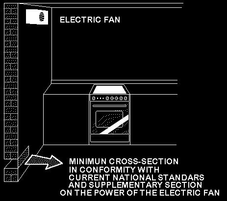
3 IMPORTANT INFORMATION FOR INSTALLING THE APPLIANCE The cooker can be installed separately, as a freestanding unit, or between kitchen units or between a kitchen unit and the wall. The device must be installed in accordance with the regulations stated in UNI 7129 and UNI 7131 standards. This appliance is not connected to devices which exhaust combustion products. Special attention must be focused on the prescriptions described below regarding room aeration and ventilation. Any hanging cabinets installed above the work surface must be located at a distance of no less than 700 mm. ROOM VENTILATION To ensure that the appliance operate correctly, the room where it is installed must be continuously ventilated. The room volume should not be less than 25 m³ and the quantity of air needed shall be based on the regular combustion of gas and on the ventilation of the room. Natural air will flow through permanent openings in the walls of the room to be ventilated: these openings will be connected with the outside environment and shall have a minimum cross-section defined by the current national standards regarding room ventilation (see Fig. 3). These openings shall be built so that they cannot be clogged. Indirect ventilation is also permitted by taking air from the rooms adjacent to the one to be ventilated. LOCATION AND AERATION The gas cooking appliances must always evacuate the combustion products by means of hoods connected to chimneys, flues or directly outside (see Fig. 4). If a hood cannot be installed, it is possible to use a fan installed on a window or directly facing outdoors, to be operated together with the appliance (see Fig. 5), provided that there is strict compliance with the ventilation regulations. HEIGHT-ADJUSTABLE FEET (figure.6) The feet are packed in the top box. The feet should be installed with the cooker close to its final installation position; the feet are not safe to move the cooker long distances. After unpacking the cooker, lift it with your foot, to fit the cooker feet in the bases at the bottom. Slowly lower the cooker so its weight is resting on the feet and on the assembly fixings. We recommend using a lifting device or pallet instead of tilting the cooker. INSTALLING THE TOEKICK PANEL (only available for some models) After installing the feet, install the cooker skirt as shown in the pictures in Figure 7 INSTALLING THE RISER Remove the 2 screws securing the hob at the rear, as shown in (figure 8) Put the upstand in place and secure at the bottom with the two screws, as shown in (figure 8) Secure the middle of the upstand using the screws provided with the upstand (figure 8) INSTALLING THE HOB RAIL AND OVEN HANDLE The rail and handle are packed with the upstand. The rail is only available on some models. Assemble the hob rail and oven handle as shown in the pictures (fig.9a 9B 9C) INSTALLING THE SYSTEM TO PREVENT OVERTURNING To prevent the appliance from accidentally overturning, the system provided must be installed. Install the system as shown in the fig.10. APPLIANCE GAS CONNECTION Before connecting the appliance to the gas network, make sure that the data on the label attached to the food warmer drawer or on the back of the cooker are compatible with what is indicated for the gas distribution network. A label attached to the last page of this handbook and in the food warmer drawer (or on the back) of the appliance indicates the appliance adjustment conditions: type of gas and operating pressure. IMPORTANT: This appliance must be installed in compliance with current national standards in force and used only in a well-ventilated room. WARNING: It should be recalled that the appliance utilises a threaded 1/2" gas cylindrical male fitting according to UNI-ISO To connect the appliance to the gas network with a flexible rubber hose, a supplemental hose nipple fitting is needed (see Fig. 11) which is supplied with the appliance. 3
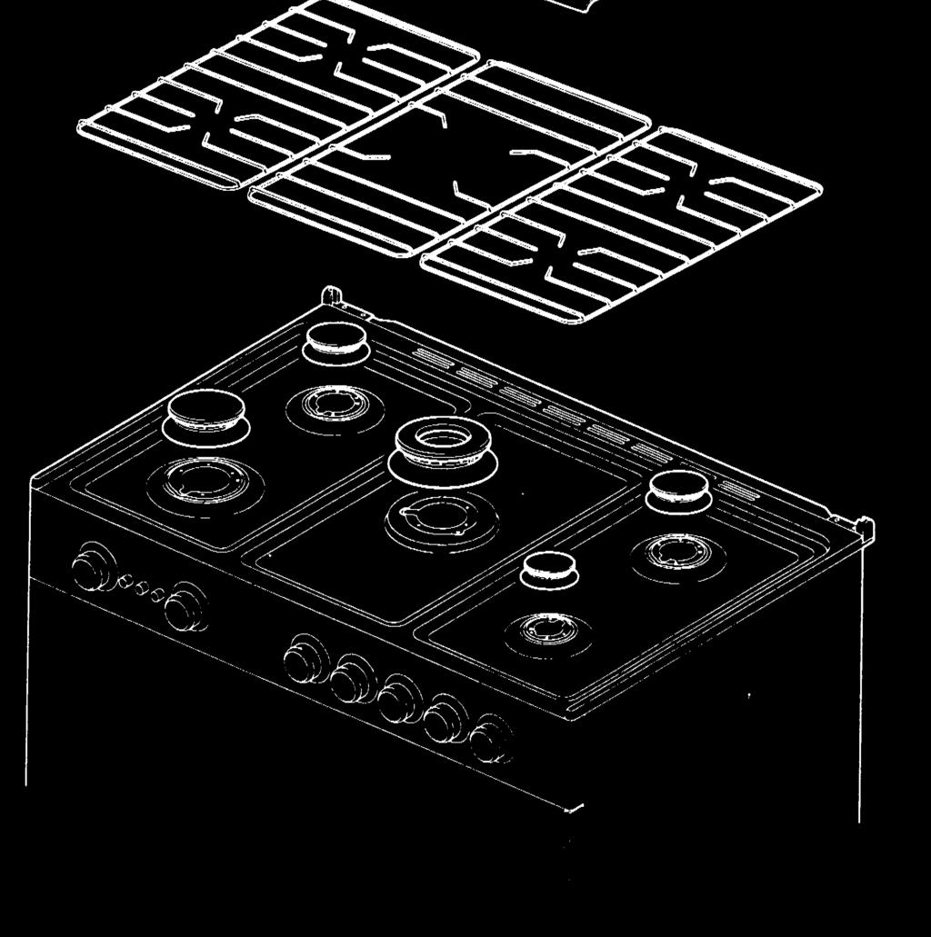
4 ADAPTATION TO DIFFERENT TYPES OF GAS FOR COOKER Before performing any maintenance operation, disconnect the appliance from the gas supply and electricity network. REPLACING THE NOZZLES TO OPERATE WITH ANOTHER TYPE OF GAS FOR COOKER: Follow the instructions below to change the burner nozzles on the work surface: 1) Pull out the plug from the electric outlet to avoid any type of electric contact. 2) Remove the grids from the work surface (Fig. 12). 3) Remove the burners 4) Unscrew the nozzles using a 7 mm spanner, and replace them (Fig.13) with those needed for the new type of gas according to what is indicated in Table 1 Follow the instructions below to change the oven burner nozzle: 1) Remove the oven level (Fig. 14). 2) Loosen the screw V and pull out the burner from the support being careful not to damage the ignition plug and the thermocouple (Fig. 15). 3) Unscrew the nozzle R using a 10 mm spanner and replace it with the nozzle needed for the new type of gas according to what is indicated in Table 1. WARNING: After completing the above-mentioned replacements, the technician must adjust the burners, as described in the paragraph below, seal any adjustment and pre-adjustment devices and apply the label on the appliance, to replace the existing one, corresponding to the new gas adjustment. This label is contained in the spare nozzle bag. TABLE N 1: Adaption to various types of gas APPLIANCE CATEGORY: II2H3+ Burner Types of Gas Pressare Nozzle Diameter Rater Capacity Reduced Capacity by-pass Diameter Mbar 1/100 mm. g/h l/h kw kcal/h kw Kcal/h 1/100 mm. Natural G , Auxiliary Butane G , Propane G , Natural G , , Semi-Rapid Butane G , , Propane G , , Natural G , Rapid Butane G , Propane G , Natural G20 20 In , In 34 reg. Out 110 out 65 reg. Dual Butane G30 30 In , , In 34 Out 69 out 65 Propane G31 37 In , , In 34 Out 69 out 65 Natural G reg. Oven Butane G Propane G BURNER ADJUSTMENT 1)Primary air adjustment: Oven burner adjustment: follow the instructions below to adjust the primary air for the over burner: 1) Remove the oven bottom. 2) Loosen the screw P and adjust the position X of the Venturi cone (Fig. 16) according to the measurements indicated in table 2. TABLE N 2: Burner primary air regulation (indicative) BURNER Type of gas Oven (mm) Natural G20 fully open Butane G30 fully open Propane G31 fully open 2) Burner "MINIMUM" adjustment: Work surface burner adjustment: follow the instructions below to adjust the work surface burner minimum: 1) Light the burner and set the knob to the MINIMUM position (small flame). 2) Remove the knob of the valve that is press fit on the rod of that valve. 3) If the cooker is not equipped with safety valves on the surface burners, insert a small slotted screwdriver into the hole on the valve rod (Fig. 17) and turn the choke screw to the right or left until the burner flame is adjusted to minimum. If the cooker is equipped with safety valves, the choke valve is not located in the rod hole, but on the valve body (see fig. 18). 4) For the gas valve of dual burner the choke valve is located on the valve body (fig. 19), the A screw adjust the outer ring, the B screw adjust the inner ring. 5) Make sure that the flame does not go out when switching quickly from the MAXIMUM to the MINIMUM position. 4
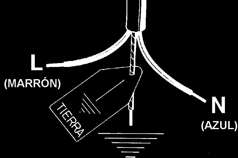
5 Oven burner adjustment: follow the instructions below to adjust the minimum: 1) Light the burner setting the knob to the MAXIMUM position. 2) Close the oven door and operate the oven for at least 10 minutes. 3) Set the knob to the MINIMUM position (corresponding to 120 ) and then remove it. 4) With a slotted screwdriver turn the choking screw (see figure 20) and, while observing the flame at the same time through the cooker porthole, evaluate the consistency of the flame so it remains on when switching quickly from the MINIMUM to the MAXIMUM position. WARNING: The above-mentioned adjustment should be made only with methane gas burners, while for those operating with liquid gas the screw must be locked at the end in a clockwise direction. The grill burner always operates at maximum and therefore no minimum adjustment is required. APPLIANCE ELECTRIC CONNECTION: The electric connection must comply with the current legal standards and regulations. Before making the connection, check that: - The system electrical rating and the current outlets are adequate for the maximum power output of the appliance (see the label applied to the bottom of the casing). - The outlet or the system is equipped with an efficient ground connection in accordance with the current legal standards and regulations. The company will not be responsible for the non-compliance with these instructions. When the connection to the power supply network is made using an outlet: - If the power cord is supplied without a plug, apply a standard plug that is suitable for the load indicated on the label. Connect the wires according to the diagram shown in FIG.21 and check that: letter L (phase) = brown wire; letter N (neutral) = blue wire; ground symbol = green-yellow wire; - The power cord must be positioned so that an overtemperature of 75 K will not be reached at any point. - Do not use reductions, adapters or splitters since they might cause false contacts and lead to dangerous overheating. When the connection is made directly to the electric network: - Use a device that ensures disconnection from the mains in which the contacts are opened to a distance that permits complete disconnection according to the conditions for over-voltage category III. - Remember that the ground wire must not be interrupted by the circuit-breaker. - As an alternative, the electric connection can also be protected by a high-sensitivity residual current circuit-breaker. - It is highly recommended to attach the special green-yellow ground wire to an efficient ground system. WARNING: If the power cord is replaced, the ground wire (yellow-green) connected to the terminal, should be longer than the other wires by about 2 cm. TABLE N 3: TYPES OF POWER CORDS Work surface operation Left Oven operation Right Oven operation Cross section Only gas burner Ventilated Gas Oven Conventional Electric Oven H05VV-F 3x1,5mm² Ventilated Electric Oven Conventional Electric Oven H05VV-F 3x2,5mm² Electric fan oven The appliance is equipped with a terminal for the electric connection placed behind, which is accessible removing the posterior casing (Fig.21A) The cable of alimentation can be : Operation at V~ : use a H05BB-F three-wire cable (cable 3x2,5 mm²) Operation at V2N~ : use a H05RR-F o H07RN-F four-wire cable (cable 4x1,5 mm²) Operation at V3N~ : use a H05RR-F o H07RN-F five-wire cable (cable 5x1,5 mm²) Fig.21B The power supply cable is suitable for appliance operating on V~ ATTENTION: The appliance conforms with the regulations of directives 90/396EEC (Gas Directive) regarding gas appliances for domestic use and the like, 73/23 (Low Voltage Directive) regarding electrical safety and 2004/108/CE, (EMC Directive) regarding electromagnetic compatibility. 5
6 APPLIANCE MAINTENANCE ATTENTION: IMPORTANT WARNINGS For cookers resting on a base ATTENTION: If the cooker rests on a base, take the measures necessary to prevent the cooker from sliding along the support base. For cookers with glass covers ATTENTION: Before opening the appliance s glass cover, carefully remove all liquid residues from the top of it. ATTENTION: Before closing the appliance s glass cover, make sure that the work surface has cooled. For cookers with electric ovens The unit becomes hot during use. Do not touch the heating elements inside the oven. For cookers with electric ovens ATTENTION: The accessible parts can become hot during use. Keep children away from the appliance. For the food warmer compartment (or drop leaf in our case) ATTENTION: The internal parts of the food warmer can become hot during use. For glass doors Do not use abrasive cleaning products or metal spatulas with sharp edges to clean the oven door s glass since this could scratch the surface and the glass could break. Do not use steam cleaners to clean the appliance. NOTE: various parts of the cooker heat up reaching temperatures which seem very high but which are actually fully within safety limits. According to these limits: 1) With the oven on at 200 C for 1 hour, front accessible parts which cannot be grasped, can reach the following temperatures: - Control panel: Tmax = Room Temperature +60 C - Glass of the oven door: Tmax = Room temperature+60 C - Metal part of the oven door: Tmax = Room temperature+45 C 2) With the oven on at 230 C for 1 hour, the parts which can be grasped, can reach the following temperatures: - Plastic knobs: Tmax = Room temperature+60 C - Metal oven door handle: Tmax = Room temperature+35 C where the room temperature is the temperature in C of the place where the appliance is installed. APPLIANCE MAINTENANCE REPLACING PARTS Before performing any maintenance operation, disconnect the appliance from the gas supply and electricity network. To replace parts such as knobs and burners, just remove them from the seats without disassembling any part of the cooker. To replace parts such as nozzle supports, valves and electric components follow the procedure described in the burner adjustment paragraph. To replace the valve or the gas thermostat, it is also necessary to disassemble the two rear gas train brackets, loosening the 4 screws (2 per bracket) that attach it to the rest of the cooker and, unscrew the nuts that attach the front burner valves to the control support, after removing all the knobs. To replace the gas or electric thermostat, also disassemble the rear cooker guard, loosening the relative screws, to be able to pull out and reposition the thermostat bulb. To replace the oven bulb, just unscrew the protection cap that projects out inside the oven. (Fig.22) WARNING: Before replacing the bulb, disconnect the appliance from the electric power supply. WARNING: The power cord supplied with the appliance is connected to that appliance with an X type connection (in compliance with standards EN , EN and subsequent amendments) for which it can be installed without the use of special tools, with the same type of cord as the one installed. If the power cord becomes worn or damaged, replace it based on the information reported in table 2. WARNING: If the power cord is replaced, the installer shall ensure that the ground cable is longer than the phase cables and also shall comply with the warnings regarding the electric connection. To replace the power cable, lift the terminal board s cover and replace the cable. TABLE 3 GAS BURNER DIMENSION Burner Dimension (mm) Auxiliary Ø 50 Semi-rapid Ø 70 Rapid Ø 95 Dual Ø 130 USE AND MAINTENANCE MANUAL 6
7 CONTROL PANEL DESCRIPTION On the control panel, small symbols show the function of each knob or key. Here as follows are the several controls that a cooker can have: the symbol or shows the disposition of burners on the worktop, the full dot identifies the burner in object (in this case the front burner on the right). the symbol or shows the running of any left oven (ventilated gas oven with electric grill, 9 positions switch) the symbol or shows the running of any right oven the symbol or shows the electric thermostat for electric left oven USING BURNERS A diagram is etched on the control panel above each knob which indicates which burner corresponds to that knob. The burners can be ignited in different ways depending on the type of appliance and its specific characteristics: - Manual lighting (it is always possible even when the power is cut off): Turn the knob anticlockwise that corresponds to the burner selected, setting it to the MAXIMUM position at the etched star (large flame Fig.23) and place a lit match up to the burner. - Electric ignition: Turn the knob counterclockwise that corresponds to the burner selected, setting it to the MAXIMUM position (large flame Fig. 23) and keep on pressing the knob in correspondence of the ignition symbol marked with a star (for cookers equipped with ignition trough knob) or press the ignition button marked with a star and release it as soon as the burner has ignited. - Burner ignition equipped with safety device (thermocouple)(fig.25): Turn the knob anticlockwise that corresponds to the burner selected, setting it to the MAXIMUM position at the etched star (large flame Fig. 23), press the knob and activate one of the above-mentioned ignition devices. Once ignited, keep pressing the knob for about 10 seconds to allow the flame to heat the thermocouple. If the burner goes out after releasing the knob, repeat the entire operation. - Use of the Dual burner (Fig.24) This model controls both the central and the external crown of the burner with just one valve. To ignite the central crown press and turn the knob to the maximum delivery position 1 and hold it down until ignition; in this position the internal flame are at maximum. Turn the knob to position 2 to have the internal crown at minimum. Turn the knob to position 3 to have the internal crown and the external crown at the maximum. Turn the knob to position 4 to have the internal crown and the external crown at the minimum. Note: It is recommended not to try to ignite a burner if the relative flame cap is not in the correct position. Tips for using burners correctly: - Use suitable pots for each burner (see tab. 4 and Fig. 26). - When the liquid is boiling, turn the knob to the MINIMUM position (small flame Fig. 23). - Always use pots with a cover. TABLE N 5 BURNER PAN DIAMETER recommended (cm) Auxiliary Semi-rapid Rapid Double ring ATTENTION: Use pots with a flat bottom WARNING: If the power is cut off, the burners can be lit with matches. When cooking foods with oil and fat, which are very flammable, the user should not leave the appliance unattended. If the appliance is equipped with a glass cover, such a cover may break when heated. Turn off all burners before lowering the cover. Do not use sprays near the appliance when it is being used. When using the burners, make sure that the handles of the pots are correctly positioned. Keep children away from the appliance. If equipped with a cover, before being closed, any food deposits should be cleaned off the built-in surface. NOTE: The use of a gas cooking appliance produces heat and humidity in the room where it is installed. Therefore, proper aeration in the room is needed while ensuring that natural ventilation openings remain 7
8 unobstructed (Fig.3) and activating the mechanical aeration device/exhaust hood or electric fan (Fig. 4 and Fig. 5). Intensive and continuous use of the appliance may require additional aeration, for example by opening a window, or more efficient aeration by increasing the power of the mechanical exhauster, if installed. USING THE GAS OVEN (left oven) GAS OVEN: All the gas oven cookers are equipped with a thermostat and safety device to adjust the cooking temperature. The oven temperature is set by turning the knob (Fig. 27) counterclockwise to match the indicator with the temperature selected. The gas oven can be combined with a gas grill or an electric grill (Fig. 27). See the specific pages for use information. FAN GAS OVEN: Operating the fan of the oven by means of the appropriate switch situated on the control panel, the circulation of warm air guarantees a uniform heat distribution. The preheating of the oven can be avoided. However for delicate baking, it is preferable to warm the oven before introducing the baking-pan. The baking system with the fan convection changes in part the various traditional baking notions. When roasting meat it is not necessary to turn the meat any more and for a roast on the spit, it is not indispensable to use the spit-roaster, but is sufficient to put the meat directly on the grate. With the use of the fan gas oven, the baking temperatures are slightly lower of about C compared to those in use with the traditional gas oven. The fan operation of the oven prevents the operation of the electric grill, which therefore cannot be used with the fan in action. The oven can also be used in a traditional way, (by not activating the fan) for foods requiring heat from the bottom, e.g. pizza. WARNING: If the burner flames are extinguished accidentally, turn off the control knob and do not try to relight the oven until after at least 1 minute. Tabella n 6 THERMOSTAT SETTING TEMPERATURE C C C C C C C C C The oven burner can be ignited in different ways: - Manual lighting (it is always possible even when the power is cut off): To light the oven, open the oven door and turn the knob so the no. 8 on the scale matches the indicator. At the same time put a lit match next to the ignition tube that is visible on the oven level (fig.28). Then press the thermostat knob (this makes the gas start to flow) and keep it pressed, after the burner has been completely lit, for 10 seconds. Release the knob and make sure that the burner remains on, otherwise repeat the operation. - Electric ignition (only for the models equipped with this device): In this case, first open the oven door, then turn the knob to the maximum temperature setting (number 8). Then press the thermostat knob (models with ignition trough knob). Wait about 10 seconds after the burner has been completely lit and then release the knob. Make sure that the burner remains on, otherwise repeat the operation. As for cookers without ignition trough knob, press the thermostat knob and the key with the spark symbol, wait about 10 seconds after the burner has been completely lit and then release the knob. Make sure that the burner remains on, otherwise repeat the operation. The ignition device should not be used for more than 15 seconds. If after that period the burner still has not been lit, do not use the device and open the door of the room or wait at least 60 seconds before trying to light the oven again. WARNING: when trying to light the oven, the door must always be open. When using the oven, leave the cooker cover open to prevent it from overheating. NOTICE: when using the oven for the first time it should be operated for minutes at a temperature of about 250 without cooking anything inside in order to eliminate any moisture and odours from the internal insulation. During normal oven use, after lighting the burner and setting the desired temperature, wait about 15 minutes before putting in any food to preheat the oven. The oven is equipped with 5 guides at different heights level (fig.29) which can be used to insert shelves or the tray. To keep the oven as clean as possible it is recommended to cook meat on the tray or on the shelf that has been inserted inside the tray. The table below lists the general cooking times and the position of the tray for different types of foods. Personal experience will help to determine any variations in the values reported in the table. In any case, it is recommended to follow the instructions of the specific recipe being used. Temperatures between brackets are referred to the use of oven with fan assisted gas. 8
9 TABLE N 7 GAS OVEN COOKING TABLE TEMP C HEIGHT MINUTES MEAT PORK ROAST 220 (210) BEEF ROAST (YOUNG STEER) 250 (240) BEEF ROAST 240 (230) VEAL ROAST 220 (210) LAMB ROAST 220 (210) ROAST BEEF 230 (230) ROAST HARE 235 (225) ROAST RABBIT 220 (210) ROAST TURKEY 235 (225) ROAST GOOSE 225 (215) ROAST DUCK 235 (225) ROAST CHICKEN 235 (225) FISH ( ) PASTRY FRUIT PIE 200 (210) TEA CAKE 190 (180) BRIOCHES 175 (165) SPONGE CAKE 235 (225) 3 20 RING CAKE 190 (180) SWEET PUFF PASTRIES 220 (210) 3 20 RAISIN LOAF 220 (210) STRUDEL 180 (170) SAVOIA COOKIES 190 (180) 3 15 APPLE FRITTERS 220 (210) 3 20 SAZOIARDI SANDWICH 220 (210) TOAST SANDWICH 250 (240) 4 5 BREAD 220 (210) 3 30 PIZZA 220 (210) 3 20 USING THE 2+0 CHANGE-OVER SWITCH (figure 30) (only left oven) (only for gas ovens and grill electric) The 2+0 change-over switch used for gas oven models. the symbol or is for oven fan and light operation, to use the gas oven or grill with fan. the symbol or is for turning on the oven light USING THE ELECTRIC THERMOSTAT (left oven) The thermostat supplied with the relative models maintains a constant temperature inside the oven at a specific temperature setting ranging from 50 C to 250 C.(fig.31) Turn the knob clockwise and align the selected temperature indicated on the ring with the index etched on the control panel. Thermostat operation is indicated by an orange light which will turn off when the temperature inside the oven is 10 C greater than the temperature setting, and will turn on when the oven is 10 C less than the temperature setting. The thermostat can control the oven elements only if the relative switch is in one of the possible oven element operating modes: if the switch is in position 0, the thermostat has not effect on the oven elements, which remain off. USING THE SWITCH (left oven) The switch installed in the multifunction oven models is used, along with the thermostat, to control the electric fan and the oven elements since they can be turned on by turning the switch knob and the thermostat knob. Turning just one of the two knobs will not have any effect on the oven except to turn on the oven light or the electric fan when inserted. The electric oven is heated by 4 elements: one on the bottom, two on the top or one circular; turning the switch knob (fig.32) turns on the element relative to the symbol indicated on the ring but to be activated the thermostat knob must be turned until the orange light turns on indicating that the element has been turned on. Placing the switch knob on any of the nine operating modes turns on the oven light, together with the relative element. Once the temperature and the 9
10 elements to be used have been set, the oven elements are turned on and off by the thermostat; therefore, it is normal for the orange light to turn on and off while the oven is working. To turn off the electric oven set the switch knob to position 0 to prevent the thermostat from controlling the elements. Setting the thermostat knob to position 0 turns off the elements but it is still possible, using the switch, to turn on the electric fan and the oven light. The switch has 9 different fixed positions corresponding to 9 different types of oven operation: - the symbol or indicates that only the oven light is turned on; - the symbol or indicates that the bottom element (1300W) and the top external element (900W) have been turned on; - the symbol or indicates that only the top external element (900W) has been turned on; - the symbol or indicates the only the bottom element (1300W) has been turned on; - the symbol or indicates that only the grill element (2000W) has been turned on; - the symbol or indicates that the top external element (900W) and the grill element (2000W) have been turned on; - the symbol or indicates that the top external element (900W), the grill element (2000W) and the electric fan have been turned on; - the symbol or indicates that the circular element (2400W) and the electric fan have been turned on; - the symbol or indicates that only the electric fan has been turned on. When the knob is set to one of these nine positions, the oven light is always on, thus indicating that the oven is being energised. USING THE THERMOSTAT WITH SWITCH IN SERIES (Right oven) (COOKERS WITH A SINGLE-CONTROL CONVENTIONAL ELECTRIC OVEN) The electric oven is controlled by an electric thermostat combined with a switch used to turn on the elements. The electric oven can be combined with an electric grill. The oven is heated by 2 elements: one on the top and one on the bottom. Turning the knob (fig.33) turns on the bottom element and the top external elements while the thermostat is used to set the temperature ranging from 50 C to 250 C. It can be adjusted using the scale indicated on the ring around the knob. An orange light turns off indicating that the temperature setting has been reached. Therefore, it is normal for this light to turn on and off while the oven is working. There are 3 fixed position beyond the 250 C setting: - the symbol o indicates the only the bottom element (900W) has been turned on; - the symbol o indicates that only the top external element (600W) has been turned on; - the symbol o indicates that only the grill element (900W) has been turned on; In these positions the temperature is not controlled by the thermostat. USING THE NATURAL CONVENTIONAL ELECTRIC OVEN When using the oven for the first time it should be operated for a maximum of 30 minutes at a temperature of about 250 to eliminate any odours generated by the internal insulation. During normal oven use, select the desired cooking temperature using the thermostat knob and wait until the orange light turns off before putting in any food. The oven is equipped with 5 guides at different heights (fig.29) which can be used to insert shelves or the tray. To keep the oven as clean as possible it is recommended to cook meat on the tray or on the shelf that has been inserted inside the tray. Table No. 7 below lists the cooking times and the position of the tray for different types of foods. Personal experience will help to determine any variations in the values reported in the table. In any case, it is recommended to follow the instructions of the specific recipe being used. 10
11 TABLE N 8 NATURAL CONVENTIONAL ELECTRIC OVEN COOKING TABLE TEMP C HEIGHT MINUTES MEAT PORK ROAST 225 4/ BEEF ROAST (YOUNG STEER) 225 4/ BEEF ROAST 250 4/ VEAL ROAST 225 4/ LAMB ROAST ROAST BEEF 230 4/ ROAST HARE 250 4/ ROAST RABBIT ROAST TURKEY ROAST GOOSE ROAST DUCK 250 4/ ROAST CHICKEN 250 4/ FISH PASTRY FRUIT PIE TEA CAKE BRIOCHES SPONGE CAKE RING CAKE SWEET PUFF PASTRIES RAISIN LOAF STRUDEL SAVOIA COOKIES APPLE FRITTERS SAZOIARDI SANDWICH TOAST SANDWICH BREAD PIZZA USING THE VENTILATED ELECTRIC OVEN (left oven) When using the oven for the first time it should be operated for a maximum of 30 minutes at a temperature of about 250 to eliminate any odours generated by the internal insulation. Before cooking, allow the oven to reach the desired temperature setting waiting for the orange light to turn off. This type of oven is equipped with a circular element around which a fan has been installed that creates forced-air circulation in the horizontal direction. Thanks to this type of operation, the ventilated oven can be used for different types of cooking at the same time, without changing the taste of each food. Only some models are equipped with a removable metallic filter applied to the rear screen which collects the fat while a roast is cooking. Therefore, it is recommended to remove this fat periodically, washing the screen with soapy water and rinsing thoroughly. To remove the metallic filter just apply slight pressure toward the top on the tab indicated by the arrow. Hot-air circulation guarantees a uniform distribution of heat. Pre-heating the oven is not necessary, but for very delicate pastries, it is recommended to heat the oven before inserting the trays. The ventilated conventional system partially changes the various notions about traditional cooking. Meat no longer needs to be turned while it is cooking and the rotisserie is no longer needed to cook a roast on the spit. Just put the meat directly on the shelf. TABLE N 9 VENTILATED ELECTRIC OVEN COOKING TABLE TEMP C HEIGHT MINUTES MEAT PORK ROAST BEEF ROAST (YOUNG STEER) BEEF ROAST VEAL ROAST LAMB ROAST ROAST BEEF ROAST HARE ROAST RABBIT ROAST TURKEY ROAST GOOSE ROAST DUCK ROAST CHICKEN
12 FISH / 4 PASTRY FRUIT PIE TEA CAKE BRIOCHES SPONGE CAKE RING CAKE SWEET PUFF PASTRIES RAISIN LOAF STRUDEL SAVOIA COOKIES APPLE FRITTERS SAZOIARDI SANDWICH TOAST SANDWICH BREAD PIZZA USING THE CONVENTIONAL ELECTRIC GRILL The electric grill can also be combined with the gas oven or electric oven. In both cases, the grill is controlled using the oven s temperature knob (see also, Using the gas or electric oven). Like the gas grill, the electric grill can be used for grilling on the oven s grill or using the roasting spit. The static electric grill must be used with the door closed. The temperature set on the thermostat (when present) must not exceed 150 C. The power of the electric grill for gas oven is 1500W. Grilling on the shelf: In this case, the shelf supplied is placed on level 1 or 2 and the foods to be grilled are placed on top, while the tray is inserted on the lower levels to collect the cooking juices. Then turn on the grill element switching the thermostat to the relative position (electric oven version). WARNING: the accessible parts may become very hot while grilling. Keep children away from the appliance while cooking. ATTENZIONE: le parti accessibili possono diventare molto calde durante l uso. I bambini dovrebbero essere tenuti a distanza. USING THE ELECTRIC GRILL WITH FAN (only left oven) The electric grill with fan is a special function for optimal grilling, with the oven rack at an intermediate position and the drip tray below. With gas oven cookers with electric grills, set the thermostat to the grill symbol and the 2+0 change-over switch to the position to turn on the 2500W grill heating element and fan motor. With cookers with a 9-setting change-over switch, set the 9+0 switch to the relative position and the electric thermostat to the temperature required, to turn on the grill heating element and fan motor. IMPORTANT: When using the electric grill with fan, do not turn the thermostat knob to not more than 175 C (between 150 and 200 C) to prevent overheating the oven front; the oven has been designed for closed-door fan grilling. Note: The cooker is equipped with the cooling fan that starts operation each time the oven knob is on a position different from 0 (zero). The fan circulates the air between the control panel and the oven door and also allows the control panel and the oven door stay at a warm temperature during the appliance operation in any condition. USING THE THERMOMETER Figure 34 The cooker is fitted with a device to measure the temperature in the middle of the oven. This lets you check the temperature inside the oven and adjust food cooking temperatures more accurately. The cooker is fitted with a device to measure the temperature in the middle of the oven. This lets you check the temperature inside the oven and adjust food cooking temperatures more accurately. Attention: the thermometer does not read the ambient temperature Attention: the position of the pointer to extinguished furnace could indicate also 50 ; such indication does not have to be considered to the aims of the operation of the thermometer. The valence of the thermometer is correct over 140 ELECTRIC OVEN When you turn on the oven, the orange light comes on to indicate that the heating elements are working: The thermometer dial will start to move towards the set temperature. The orange light will keeping coming on and off, indicating that the heating elements are working to maintain the temperature inside the oven. The light may go off for a few minutes before the thermometer has reached the temperature required. This is normal, because operation of the heating elements is regulated so that heat is distributed properly inside the oven. 12
13 Heat is optimally distributed inside the oven when the thermometer dial has stopped. If the oven temperature drops or goes up, the thermometer dial will follow these variations in the same way. When the oven is turned off, the temperature on the thermometer will slowly drop until it reaches departure position. NOTE: The temperatures on the knob are indicative. Follow the thermometer temperature for cooking. GAS OVEN When the oven is turned on, the burner will start working at the maximum and the thermometer dial will start to move towards the set temperature. The flame may die down before the thermometer has reached the temperature required. This is because burner power is reduced so that heat can be evenly distributed inside the oven. Heat is optimally distributed inside the oven when the thermometer dial has stopped. When the oven is turned off, the temperature on the thermometer will slowly drop until it reaches departure position. NOTE: The Thermostat Position and Oven Temperature correspondence in table no. 6 is indicative and depends on various factors such as the type of gas and supply pressure. Follow the thermometer temperature for cooking. NOTE: it is normal to record different temperatures from those indicated on the panel thermometer, when you measure the temperature in the middle of the oven using a different thermometer. The temperature indicated by the thermometer is the mean temperature inside the oven and does not indicate the temperature of any single point. USING THE SELF-CLEANING OVEN On models which have this device, the self-cleaning oven differs from normal ovens because the inner surfaces are coated with a special micro-porous enamel that absorbs and eliminates grease residues during cooking. If liquid grease is released, self-cleaning is not sufficient, so wipe the grease stains with a damp sponge and then heat the oven to the maximum temperature, wait for it to cool down and wipe again with a damp sponge. CLEANING THE APPLIANCE Before any cleaning, unplug the appliance and turn off the gas tap. Do not use steam cleaners to clean the appliance Cleaning the hob: Clean the burner heads, enamelled steel pan supports, enamelled caps and flame spreaders regularly using warm soapy water. Rinse and dry well. Use a cloth to wipe away any liquids spilt from pans. If the gas tap does not open or close easily, do not force it, but seek technical assistance immediately. Cleaning enamelled parts: Clean enamelled parts frequently with soapy water, to keep their characteristics unaltered. Never use abrasive powders. Do not leave acid or alkaline substances (vinegar, lemon juice, salt, tomato juice, etc.) on enamelled parts, and clean the parts when still warm. Cleaning stainless steel parts: Clean with soapy water then dry with a soft cloth. Use special stainless steel cleaning products regularly to maintain the shine. Never use abrasive powders. Cleaning the flame spreaders: As the flame spreaders rest on the hob surface, to clean them, remove and wash with soapy water. Dry well and make sure the holes are not obstructed, before putting them back in position. Cleaning the oven glass panel: The oven glass panel can be removed. After opening the doors and blocking the hinges (figure 35) remove the glass panel (figure 36) and clean. Clean the panel when the oven is cold, using a damp cloth. Do not use abrasive products. Put the glass panel back, making sure the smooth part is on the outside and the printed part inside the oven door. Then release the hinges. Note: do not release the hinges if the glass panel is not fitted on the door. Cleaning inside the oven: To make heavy-duty cleaning easier, the door can be removed as follows. After opening the door and blocking the hinges (figure 35), put the door in a semi-open position and pull towards yourselves until it is released. To reassemble, proceed as above in reverse. The side racks can also be removed, by removing the nuts securing them to the oven. Cast iron or aluminium strip racks: Soft aluminium-bottomed pans are not recommended, to prevent leaving permanent marks on the rack surface which cannot be removed with normal washing. 13


14 Fig. 1 Fig. 3 Fig. 4 Fig. 5 Fig.6 14

15 Fig.7 15
16 Fig.8 16

17 Fig.9A 17

18 Fig.9B 18

19 Fig.9C 19


20 Fig.10 Fig.11 fig.12 fig.13 20


21 fig.14 fig.15 fig.16 Fig. 17 Fig. 18 Fig. 19 T fig.20 fig.21 fig.21a fig.21b Fig.22 Fig.23 Fig.23 Fig.24 21


22 Fig.24 Fig.25 Fig.26 fig.27 fig.27 fig.28 fig.29 Fig.30 Fig.30 Fig. 31 Fig. 31 Fig. 32 Fig. 32 Fig


23 Fig. 33 Fig. 34 Fig.35 Fig.36 23
24 24 Cod
INSTALLATION, MAINTENANCE AND USE INSTRUCTIONS FOR FREE-STANDING COOKERS 90x60 cm (type M9V) 60x60 cm (type M6V) VEF91EG VEF61EG
 60x60 cm (type M6V) VEF91EG VEF61EG") INSTALLATION, MAINTENANCE AND USE INSTRUCTIONS FOR FREE-STANDING COOKERS 90x60 cm (type M9V) 60x60 cm (type M6V) VEF91EG VEF61EG READ THE INSTRUCTION BOOKLET BEFORE INSTALLING AND USING THE APPLIANCE.
INSTALLATION, MAINTENANCE AND USE INSTRUCTIONS FOR FREE-STANDING COOKERS 90x60 cm (type M9V) 60x60 cm (type M6V) VEF91EG VEF61EG READ THE INSTRUCTION BOOKLET BEFORE INSTALLING AND USING THE APPLIANCE.
User Instructions FREESTANDING GAS RANGES BERTAZZONI
 User Instructions FREESTANDING GAS RANGES BERTAZZONI DIMENSIONS: 36 (915 mm)(w) x 253/16 (640 mm)(d) x36 (915 mm)(h) Models X365GGVX (X36 5 00 X) [M3W0GTU4X(2 or 5)A] Models X366GGVX (X36 6 00 X) [M3Y0GTU4X(2
INSTALLATION, MAINTENANCE AND USE INSTRUCTIONS FOR FREE-STANDING COOKERS 70x60 cm (type MKV)
") INSTALLATION, MAINTENANCE AND USE INSTRUCTIONS FOR FREE-STANDING COOKERS 70x60 cm (type MKV) AM75C61BX TU75C61BX AM75C71BX TU75C71BX READ THE INSTRUCTION BOOKLET BEFORE INSTALLING AND USING THE APPLIANCE.
INSTALLATION, MAINTENANCE AND USE INSTRUCTIONS FOR FREE-STANDING COOKERS 70x60 cm (type MKV) AM75C61BX TU75C61BX AM75C71BX TU75C71BX READ THE INSTRUCTION BOOKLET BEFORE INSTALLING AND USING THE APPLIANCE.
Contents. Downloaded from manuals search engine
 Contents 1. INSTRUCTIONS FOR SAFE AND PROPER USE 6. INSTALLATION 8 3. DESCRIPTION OF CONTROLS 30 4. USE OF THE OVEN 35 5. AVAILABLE ACCESSORIES 36 6. COOKING HINTS 37 7. CLEANING AND MAINTENANCE 43 8.
operating & installation instructions SA20XMFR
 operating & installation instructions SA20XMFR Contents 1. INSTRUCTIONS FOR SAFE AND PROPER USE 26 2. INSTALLATION 28 3. DESCRIPTION OF CONTROLS 30 4. USE OF THE OVEN 35 5. AVAILABLE ACCESSORIES 36 6.
INSTRUCTIONS AND ADVICE FOR THE USE, INSTALLATION AND MAINTENANCE OF BUILT-IN ELECTRIC HOBS
 INSTRUCTIONS AND ADVICE FOR THE USE, INSTALLATION AND MAINTENANCE OF BUILT-IN ELECTRIC HOBS Dear Customer, Thank you for having purchased one of our products. We are certain that this new, modern, functional
HG 675 CX 60 HG 675 CN 60 HG 675 CW 60
 HG 675 X 60 HG 675 CX 60 HG 675 CN 60 HG 675 CW 60 1 2 1. : 93/68: 90/396: 2006/95/CE: 2004/108/CE: - 1935/2004:. 2002/95/CE: RoHS 2.,.,,,,...,. (,..)..,,.,. ( ),,, ;,,.,.....,.,,,,,,...,. (..),,.,..,.,,,,
PROF. RANGE COOKER MODEL: EPRC-A6456GE(SS) Owner s Manual Please read this manual carefully before operating your set. Retain it for future reference.
 Owner s Manual Please read this manual carefully before operating your set. Retain it for future reference.") PROF. RANGE COOKER MODEL: EPRC-A6456GE(SS) Owner s Manual Please read this manual carefully before operating your set. Retain it for future reference. Record model number and serial number of the set.
PROF. RANGE COOKER MODEL: EPRC-A6456GE(SS) Owner s Manual Please read this manual carefully before operating your set. Retain it for future reference. Record model number and serial number of the set.
Contents THESE INSTRUCTIONS ARE VALID ONLY FOR END USER COUNTRIES WHOSE IDENTIFICATION SYMBOLS APPEAR ON THE COVER OF THIS MANUAL.
 Contents 1. INSTRUCTIONS FOR SAFE AND PROPER USE 38. INSTALLING THE APPLIANCE 40 3. ADAPTATION TO DIFFERENT TYPES OF GAS 43 4. FINAL OPERATIONS 45 5. DESCRIPTION OF CONTROLS 47 6. USING THE COOKING HOB
Contents THESE INSTRUCTIONS ARE VALID ONLY FOR END USER COUNTRIES WHOSE IDENTIFICATION SYMBOLS APPEAR ON THE COVER OF THIS MANUAL.
 Contents 1. INSTRUCTIONS FOR SAFE AND PROPER USE 36. INSTALLING THE APPLIANCE 38 3. ADAPTATION TO DIFFERENT TYPES OF GAS 40 4. FINAL OPERATIONS 4 5. DESCRIPTION OF CONTROLS 44 6. USING THE COOKING HOB
OVENS AUS. Installation - Use - Maintenance. Oven models: 60cm Built in Ovens
 OVENS Installation - Use - Maintenance AUS Oven models: 60cm Built in Ovens 539.07.031 539.07.041 GENERAL INFORMATION Please read this booklet thoroughly before you use this appliance. It is important
GAS COOKER GAS OVEN SERIES. Owner s Manual Please read this manual carefully before operating your set. Retain it for future reference.
 GAS COOKER GAS OVEN SERIES Owner s Manual Please read this manual carefully before operating your set. Retain it for future reference. Record model number and serial number of the set. See the label attached
INSTRUCTION MANUAL BUILT-IN HOBS CIR900X
 INSTRUCTION MANUAL BUILT-IN HOBS CIR900X ENGLISH 3-19 Thank you for choosing our product. We advise you to read this manual carefully. It contains all necessary instructions for maintaining unaltered the
INSTALLATION, MAINTENANCE AND USE INSTRUCTIONS FOR FREE-STANDING COOKERS 90x60 cm GIANT OVEN APPLY DATA LABELS
 INSTALLATION, MAINTENANCE AND USE INSTRUCTIONS FOR FREE-STANDING COOKERS 90x60 cm GIANT OVEN APPLY DATA LABELS 1 3100248 READ THE INSTRUCTION BOOKLET BEFORE INSTALLING AND USING THE APPLIANCE. It is important
Contents. 1. Instructions for safety and use 20
 Contents 1. Instructions for safety and use 20 2. Positioning in the counter top 21 2.1 Fixing to the supporting structure 21 2.2 Positioning the adhesive sponge 22 2.3 Positioning the fastening clips
SA990XR-8. operating and installation instructions
 SA990XR-8 operating and installation instructions Contents 1 INSTRUCTIONS FOR USE... 3 SAFETY PRECAUTIONS... 34 3 ENVIROMENTAL RESPONSIBILITY... 36 4 INSTALLATION... 37 5 DESCRIPTION OF CONTROLS... 39
Contents THESE INSTRUCTIONS ARE VALID ONLY FOR END USER COUNTRIES WHOSE IDENTIFICATION SYMBOLS APPEAR ON THE COVER OF THIS MANUAL.
 Contents 1. INSTRUCTIONS FOR SAFE AND PROPER USE 44. INSTALLING THE APPLIANCE 46 3. ADAPTATION TO DIFFERENT TYPES OF GAS 50 4. FINAL OPERATIONS 5 5. DESCRIPTION OF CONTROLS 54 6. USING THE COOKING HOB
SAFEGUARDING THE ENVIRONMENT IMPORTANT NOTES BEFORE USING THE OVEN OVEN ACCESSORIES CARE AND MAINTENANCE TROUBLESHOOTING GUIDE AFTER SALES SERVICE
 INSTRUCTIONS FOR USE SAFEGUARDING THE ENVIRONMENT IMPORTANT NOTES BEFORE USING THE OVEN OVEN ACCESSORIES CARE AND MAINTENANCE TROUBLESHOOTING GUIDE AFTER SALES SERVICE To make the most of your new oven,
INSTRUCTIONS FOR USE. To make the most of your new oven, read the user's instructions carefully and keep them on hand for consultation in the future.
 INSTRUCTIONS FOR USE INSTALLATION...4 SAFEGUARDING THE ENVIRONMENT... 7 IMPORTANT NOTES... 7 BEFORE USING THE OVEN... 8 OVEN ACCESSORIES... 9 CARE AND MAINTENANCE... 10 TROUBLESHOOTING GUIDE... 12 AFTER
Contents THESE INSTRUCTIONS ARE VALID ONLY FOR THE END USER COUNTRIES WHOSE IDENTIFICATION SYMBOLS APPEAR ON THE COVER OF THIS MANUAL.
 Contents 1. INSTRUCTIONS FOR SAFE AND PROPER USE 4 2. INSTALLATION OF THE APPLIANCE 6 3. ADAPTATION TO DIFFERENT TYPES OF GAS 9 4. FINAL OPERATIONS 12 5. DESCRIPTION OF CONTROLS 14 6. USE OF THE HOB 16
Belling. Gas Hob GHU573 - GHU573T GHU70GE - GHU70TGE - GHU70GC GHU70TGC - GHU60GC INSTALLATION AND USER INSTRUCTIONS
 Belling Gas Hob GHU573 - GHU573T GHU70GE - GHU70TGE - GHU70GC GHU70TGC - GHU60GC INSTALLATION AND USER INSTRUCTIONS Note: This appliance is supplied for use with Natural Gas and can be converted to LPG
SAFEGUARDING THE ENVIRONMENT IMPORTANT NOTES BEFORE USING THE OVEN OVEN ACCESSORIES CARE AND MAINTENANCE TROUBLESHOOTING GUIDE AFTER SALES SERVICE
 31002018GB.fm Page 11 Tuesday, December 2, 2008 10:29 PM INSTRUCTIONS FOR USE SAFEGUARDING THE ENVIRONMENT IMPORTANT NOTES BEFORE USING THE OVEN OVEN ACCESSORIES CARE AND MAINTENANCE TROUBLESHOOTING GUIDE
3gb53231b.fm5 Page 12 Friday, April 11, :21 PM
 3gb53231b.fm5 Page 12 Friday, April 11, 2003 12:21 PM INSTRUCTIONS FOR USE BEFORE USING THE COOKTOP SUGGESTIONS FOR ENVIRONMENT PROTECTION PRECAUTIONS AND GENERAL ADVICE ENERGY SAVING TIPS CARE AND MAINTENANCE
BSF60WH / BSF60SS BUILT IN ELECTRIC FAN OVEN. Instruction Manual. Please read these instructions carefully before use and retain for future reference
 BSF60WH / BSF60SS BUILT IN ELECTRIC FAN OVEN Instruction Manual Please read these instructions carefully before use and retain for future reference SAFETY INSTRUCTIONS Important: This appliance is not
INSTRUCTIONS FOR THE INSTALLER
 Contents 1. INSTRUCTIONS FOR SAFETY AND USE... 3. INSTALLATION... 35 3. DESCRIPTION OF CONTROLS... 37 4. USING THE OVEN... 43 5. AVAILABLE ACCESSORIES... 45 6. COOKING HINTS... 46 7. CLEANING AND MAINTENANCE...
Porter & Charles OPERATION MANUAL. Gas Cooktop CG60S, CG76S, CG90S, CG60W, CG90W
 Porter & Charles OPERATION MANUAL Gas Cooktop CG60S, CG76S, CG90S, CG60W, CG90W Congratulations on the purchase of your Porter & Charles appliance. We are sure it will provide many years of great cooking
EV6004WH. Built-In Electric Oven User Manual
 EV6004WH Built-In Electric Oven User Manual ACKNOWLEDGMENT Thank you for purchasing our product. We hope you enjoy using the many features and benefits it provides. Before using this product please study
BERTAZZONI. Installation, Service and User Instructions. MODEL [MLS0GTU4X(2 or 5)A] FREESTANDING GAS RANGES
![BERTAZZONI. Installation, Service and User Instructions. MODEL [MLS0GTU4X(2 or 5)A] FREESTANDING GAS RANGES](/thumbs/91/107403083.jpg "BERTAZZONI. Installation, Service and User Instructions. MODEL [MLS0GTU4X(2 or 5)A] FREESTANDING GAS RANGES") Installation, Service and User Instructions FREESTANDING GAS RANGES BERTAZZONI DIMENSIONS: 24 (605 mm)(w) x 25 1/8 (640 mm)(d) x36 (911 mm)(h) MODEL X244GGVX [MLS0GTU4X(2 or 5)A] 310287 IMPORTANT - PLEASE
Installation, Service and User Instructions FREESTANDING GAS RANGES BERTAZZONI DIMENSIONS: 24 (605 mm)(w) x 25 1/8 (640 mm)(d) x36 (911 mm)(h) MODEL X244GGVX [MLS0GTU4X(2 or 5)A] 310287 IMPORTANT - PLEASE
INSTRUCTIONS FOR USE ACM 640 IX
 INSTRUCTIONS FOR USE ACM 640 IX INSTALLATION INSTRUCTIONS BEFORE USING THE APPLIANCE PRECAUTIONS AND GENERAL ADVICE ENERGY SAVING TIPS OVEN ACCESSORIES CLEANING AND MAINTENANCE TROUBLESHOOTING GUIDE AFTER-SALES
Contents authorised persons
 Contents 1. INSTRUCTIONS FOR SAFE AND PROPER USE 4 2. POSITIONING OF THE HOB 6 3. GAS CONNECTION 10 4. ELECTRICAL CONNECTION 11 5. ADAPTATION TO DIFFERENT TYPES OF GAS 12 6. FINAL OPERATIONS 14 7. USING
Proline GAS HOB Model TCG40IX Instruction Book
 Proline GAS HOB Model TCG40IX Instruction Book GB Operating and Installation Instructions Index Technical data and specifications...... 3 Installation...................... 3-6 Ventilation........................
UBGHFF60W 60cm Gas on Glass Gas Hob
 UBGHFF60W 60cm Gas on Glass Gas Hob GB [02] x 1 [03] x 2 [04] x 1 [01] x 1 [08] x 4 [05] x 2 [09] x 1 [06] x 1 [07] x 4 [10] x 4 [11] x 1 TEMPLATE TEMPLATE UBGHFF60W GB Built-in 60cm Gas on Glass Gas Hob
INSTALLATION, MAINTENANCE AND USE INSTRUCTIONS BERTAZZONI RANGE COOKERS
 INSTALLATION, MAINTENANCE AND USE INSTRUCTIONS BERTAZZONI RANGE COOKERS Single Electric Ovens: Double Electric Ovens: A 90 5 MFE AD 90 5 MFE READ THE INSTRUCTION BOOKLET BEFORE INSTALLING AND USING THE
Operating Instructions
 Operating Instructions COOKER AND OVEN English, 1 I5ESH/UK I5ESH1/UK Contents WARNING,2 Installation, 3 Positioning and levelling Electrical connection Table of characteristics Description of the appliance,
Installation, Service and User Instructions FREESTANDING GAS RANGES BERTAZZONI. DIMENSIONS: 30 (762 mm)(w) x 253/16 (640 mm)(d) x36 (915 mm)(h)
(w) x 253/16 (640 mm)(d) x36 (915 mm)(h)") Installation, Service and User Instructions FREESTANDING GAS RANGES BERTAZZONI DIMENSIONS: 30 (762 mm)(w) x 253/16 (640 mm)(d) x36 (915 mm)(h) Models X304GGVX [M7S0GTU4X(2 or 5)A] IMPORTANT - PLEASE READ
Installation, Service and User Instructions FREESTANDING GAS RANGES BERTAZZONI DIMENSIONS: 30 (762 mm)(w) x 253/16 (640 mm)(d) x36 (915 mm)(h) Models X304GGVX [M7S0GTU4X(2 or 5)A] IMPORTANT - PLEASE READ
Operating Instructions HOB Contents
 THP 641 W/IX/I English Operating Instructions HOB Contents Operating Instructions,1 Warnings,2 Assistance,2 Description of the appliance,3 Installation,4 Start-up and use,7 Precautions and tips,7 Maintenance
INSTALLATION GUIDE / USER GUIDE GB IE
 BUILT-IN OVEN OB60 double oven under bench models INSTALLATION GUIDE / USER GUIDE GB IE Contents 1 Safety and warnings 2 Installation instructions 6 Using your oven for the first time 14 Clock and timer
DUAL FUEL COOKER. User Manual. Model Number: DD60W
 DUAL FUEL COOKER User Manual Model Number: DD60W REGISTER TO ACTIVATE YOUR 2 YEAR PARTS WARRANTY SERVIS.CO.UK 0333 577 7232 Your appliance comes with a free one year parts and labour warranty. Register
PC 640 GB. Built-in cooking tables 60 Instructions for installation and use
 PC 640 GB Built-in cooking tables 60 Instructions for installation and use Congratualtions on choosing an Ariston appliance, which you will find is dependable and easy to use. We recommend that you read
HVG620 & HVG720 Gas Hob Manual for Installation, Use and Maintenance
 HVG620 & HVG720 Gas Hob Manual for Installation, Use and Maintenance Customer Care Department The Group Ltd. Harby Road Langar Nottinghamshire NG13 9HY T : 01949 862 012 F : 01949 862 003 E : customer
Installation, Service and User Instructions FREESTANDING GAS RANGES BERTAZZONI. DIMENSIONS: 48 (W) x 25 1/8 (D) x 35 1/ /2"(H) MODEL:
 x 25 1/8 (D) x 35 1/ /2(H) MODEL:") Installation, Service and User Instructions FREESTANDING GAS RANGES BERTAZZONI DIMENSIONS: 48 (W) x 25 1/8 (D) x 35 1/8 + 1 1/2"(H) MODEL: X486GGGVX [MTYKQZU4X(2 or 5)A] 310286 IMPORTANT - PLEASE READ
Installation, Service and User Instructions FREESTANDING GAS RANGES BERTAZZONI DIMENSIONS: 48 (W) x 25 1/8 (D) x 35 1/8 + 1 1/2"(H) MODEL: X486GGGVX [MTYKQZU4X(2 or 5)A] 310286 IMPORTANT - PLEASE READ
Contents. 1. Instructions for safe and proper use Positioning of hob Attachment to support structure Electrical connection 22
 Contents 1. Instructions for safe and proper use 19 2. Positioning of hob 20 2.1 Attachment to support structure 20 3. Electrical connection 22 4. Gas connection 23 4.1 Connection to LPG 24 4.2 Ventilation
BSM60SS / BSM60WH BUILT IN MULTI-FUNCTION ELECTRIC FAN OVEN. Instruction Manual
 BSM60SS / BSM60WH BUILT IN MULTI-FUNCTION ELECTRIC FAN OVEN Instruction Manual Please read these instructions carefully before use and retain for future reference CONTENTS Safety Instructions 2 Specifications
MHG201 Gas Hob Manual for Installation, Use and Maintenance
 MHG201 Gas Hob Manual for Installation, Use and Maintenance 1 Customer Care Department The Group Ltd. Harby Road Langar Nottinghamshire NG13 9HY T : 01949 862 012 F : 01949 862 003 E : customer.care@cda.eu
BUILT-IN OVEN MODEL: EBO-E7081D(SS) Owner s Manual Please read this manual carefully before operating your set. Retain it for future reference.
 Owner s Manual Please read this manual carefully before operating your set. Retain it for future reference.") BUILT-IN OVEN MODEL: EBO-E7081D(SS) Owner s Manual Please read this manual carefully before operating your set. Retain it for future reference. Record model number and serial number of the set. See the
BUILT-IN OVEN MODEL: EBO-E7081D(SS) Owner s Manual Please read this manual carefully before operating your set. Retain it for future reference. Record model number and serial number of the set. See the
INSTALLATION AND OPERATING INSTRUCTION BOOKLET
 INSTALLATION AND OPERATING INSTRUCTION BOOKLET LIBERTY SINGLE ELECTRIC FAN OVEN MODELS C210 F/A & C210 F/W IMPORTANT: You must read this instruction Book before installing or using this appliance and retain
T-60cm-OVEN-SS T-60cm-OVEN-CM T-60cm-OVEN-BL
 T-60cm-OVEN-SS T-60cm-OVEN-CM T-60cm-OVEN-BL USER INSTRUCTIONS GENERAL WARNINGS Read carefully all the instructions contained in this booklet. It provides you with important information regarding the safe
Operating Instructions
 Operating Instructions OVEN English, 1 FI 31 K.B FI 31 K.B IX FIE 36 K.B FIE 36 K.B IX Contents Installation, 2-3 Positioning Electrical connections Data plate Description of the appliance, 4 Overall view
User Manual. 600mm, 700mm & 900mm Gas Cooktops Model No. CF6GS, CF6GW, CF7GS, CF9GS
 User Manual 600mm, 700mm & 900mm Gas Cooktops Model No. CF6GS, CF6GW, CF7GS, CF9GS For all product enquires, including warranty support, please contact our Customer Care team 1800 444 357 or email customercare@hapl.com.au
Operating Instructions HOB
 PHN 942 T/IX/A English Operating Instructions HOB Operating Instructions,1 Warnings,2 Assistance,3 Description of the appliance,4 Installation,5 Start-up and use,9 Precautions and tips,9 Maintenance and
Installation instructions. Built-in oven. and User guide NZ AU GB IE. OB60 single & double multifunction models
 Installation instructions and User guide Built-in oven OB60 single & double multifunction models NZ AU GB IE Contents 1 Safety and warnings 2 Installation instructions 6 SEVEN-FUNCTION SINGLE OVEN MODELS
Downloaded from manuals search engine. EP6004SX Built-In Electric Oven User Manual
 EP6004SX Built-In Electric Oven User Manual ACKNOWLEDGMENT Thank you for purchasing our product.we hope you enjoy using the many features and benefits it provides. Before using this product please study
Operating Instructions HOB Contents
 PAA 642 /I(WH) PAA 642 /I(BK) UK English Operating Instructions HOB Contents Operating Instructions,1 Warnings,2 Assistance,3 Description of the appliance,4 Installation,5 Start-up and use,9 Precautions
Operating Instructions HOB Contents
 PAA 642 /I(WH) PAA 642 /I(BK) UK English Operating Instructions HOB Contents Operating Instructions,1 Warnings,2 Assistance,2 Description of the appliance,3 Installation,4 Start-up and use,7 Precautions
Instructions for Use and Installation Multifunction Ovens. Mechanical Timer models
 Instructions for Use and Installation Multifunction Ovens Mechanical Timer models Contents For Your Safety..................................... 3 Use and Care Controls...........................................
HOW TO USE YOUR 2500 RANGE L.P.G. COOKER OR HOB UNIT
 HOW TO USE YOUR 2500 RANGE L.P.G. COOKER OR HOB UNIT CAUTION These instructions must be read and understood before proceeding with the installation and to avoid any possibility of accident it is essential
CTEC50WH CTEC60WH CTEC60BK OPERATING AND INSTALLATION INSTRUCTIONS OF ELECTRIC DOUBLE OVEN
 TM CTEC50WH CTEC60WH CTEC60BK EN OPERATING AND INSTALLATION INSTRUCTIONS OF ELECTRIC DOUBLE OVEN Dear Customer, Thank you for purchasing this Cooking Appliance. The safety precautions and recommendations
Contents qualified technician
 Contents 1. INSTRUCTIONS FOR SAFE AND PROPER USE 9. INSTALLATION 31 3. DESCRIPTION OF CONTROLS 34 4. USE OF THE OVEN 40 5. AVAILABLE ACCESSORIES 4 6. COOKING HINTS 43 7. CLEANING AND MAINTENANCE 47 8.
DOUBLE OVEN. Instructions for use - Installation advice. Before operating this oven, please read these instructions carefully P A U
 P A U TO DOUBLE OVEN model CKB 300 Instructions for use - Installation advice Before operating this oven, please read these instructions carefully 2 CONTENTS Page Number Introduction.....................................
Owner s Manual GEMINI PETIT CHEF MULTIFUNCTION THERMOFAN
 Owner s Manual GEMINI PETIT CHEF MULTIFUNCTION THERMOFAN EYE LEVEL OVEN CONTENTS 2 Introduction 2 Unpacking 2 Cupboard Design 2 Safety Advice 3 Installation 3 Electrical Installation 4 The Control Panel
installation and operating instructions SA708X oven
 installation and operating instructions SA708X oven Contents 1. INSTRUCTIONS FOR SAFE AND PROPER USE 4. INSTALLATION 6 3. DESCRIPTION OF CONTROLS 9 4. USE OF THE OVEN 19 5. AVAILABLE ACCESSORIES 0 6. COOKING
Operating Instructions
 Operating Instructions OVEN English, FIE 6 K.B FIE 6 K.B IX Contents Installation, - Positioning Electrical connections Data plate Description of the appliance, Overall view Control panel Start-up and
PROF. RANGE COOKER MODEL: EPRC-9850FE/SS EPRC-9860E/SS. Owner s Manual Please read this manual carefully before operating your set.
 PROF. RANGE COOKER MODEL: EPRC-9850FE/SS EPRC-9860E/SS Owner s Manual Please read this manual carefully before operating your set. Retain it for future reference. Record model number and serial number
HOW TO USE YOUR 2000 RANGE L.P.G. COOKER OR HOB UNIT
 HOW TO USE YOUR 2000 RANGE L.P.G. COOKER OR HOB UNIT CAUTION These instructions must be read and understood before proceeding with the installation and to avoid any possibility of accident it is essential
OE606X FAN FORCED OVEN
 Instructions for the Use and Care and Installation of OE606X FAN FORCED OVEN Dear Customer You will find that the clean lines and modern look of your Blanco oven blends in perfectly with your kitchen
Contents authorised persons
 Contents 1. INSTRUCTIONS FOR SAFE AND PROPER USE 4. INSTALLATION OF THE APPLIANCE 6 3. GAS CONNECTION 7 4. ADAPTATION TO DIFFERENT TYPES OF GAS 10 5. FINAL OPERATIONS 1 6. DESCRIPTION OF CONTROLS 14 7.
NW 50ES WHI/ NW 50ES BLK/ OPERATING AND INSTALLATION INSTRUCTIONS OF ELECTRICAL FREESTANDING OVEN
 NW 50ES WHI/444443914 NW 50ES BLK/444443915 OPERATING AND INSTALLATION INSTRUCTIONS OF ELECTRICAL FREESTANDING OVEN Dear Customer, Thank you for purchasing this Cooking Appliance. The safety precautions
FRANKE DESIGNER GAS COOKTOP 90CM
 page 1 of 7 510 880 45 480 Min 50 860 Min 600 SPECIFICATIONS Recommended use Material Colour availability Weight Dimensions Voltage Domestic Stainless Steel Stainless Steel 18.2kg 880 x 510 x 45mm 220-240V
BUILT-IN GAS HOB. Important - Please read these instructions fully before using AG60GNSS AG60GNW
 BUILT-IN GAS HOB Operating & Installation Instructions -Please keep for future reference AG60GNSS AG60GNW Important - Please read these instructions fully before using These instructions contain important
SAFETY INSTRUCTIONS IMPORTANT TO BE READ
 SAFETY INSTRUCTIONS EN IMPORTANT TO BE READ AND OBSERVED Before using the appliance read these safety instructions. Keep them nearby for future reference. These instructions are valid if the country symbol
Electrical Double Oven
 0 0 0 Electrical Double Oven Operating & Installation Instructions -Please keep for future reference AE66DCW AE66DCA AE66DCSS Important - Please read these instructions fully before using These instructions
Cooker Maxioven Instructions for installation and use KP 59 MS.C (X)/G
/G") Cooker Maxioven Instructions for installation and use KP 59 MS.C (X)/G Cooker Maxioven Instructions for installation and use Congratualtions on choosing an INDESIT appliance, which you will find is dependable
Cooker Maxioven Instructions for installation and use KP 59 MS.C (X)/G Cooker Maxioven Instructions for installation and use Congratualtions on choosing an INDESIT appliance, which you will find is dependable
Operating Instructions for the KM 410 Electric Grill
 Operating Instructions for the KM 410 Electric Grill To prevent accidents and machine damage, ]ö read the Operating Manual before installation or use. M.-Nr. 05 060 910 Contents Contents Description of
Instructions for use
 GB EN Instructions for use These instructions are also available at: docs.kitchenaid.eu Product description and symbols 4 Control symbols 4 Using the burners 4 Practical advice on using the hob 5 Positioning
INSTRUCTIONS AND ADVICE FOR THE USE, INSTALLATION AND MAINTENANCE OF BUILT-IN ELECTRIC HOBS
 INSTRUCTIONS AND ADVICE FOR THE USE, INSTALLATION AND MAINTENANCE OF BUILT-IN ELECTRIC HOBS Dear Customer, Thank you for having purchased one of our products. We are certain that this new, modern, functional
Built-in Conventional oven
 Built-in Conventional oven LAM3208 User Manual 2 CONTENTS S afety information 2 S afety instructions 3 Product description 5 B efore first use 6 Daily use 6 Using the accessories 7 Additional functions
BEL FS50ET SIL/ BEL FS50ET BLK/ BEL FS50ET WHI/ OPERATING AND INSTALLATION INSTRUCTIONS OF ELECTRIC TWIN CAVITY
 BEL FS50ET SIL/444443922 BEL FS50ET BLK/444443921 BEL FS50ET WHI/444443920 OPERATING AND INSTALLATION INSTRUCTIONS OF ELECTRIC TWIN CAVITY Dear Customer, Thank you for purchasing this Cooking Appliance.
BC391.2TCSS 90cm Single cavity dual fuel range cooker with flame failure
 BC391.2TCSS 90cm Single cavity dual fuel range cooker with flame failure 1 User Manual for your Baumatic BC391.2TCSS 90 cm Single cavity dual fuel range cooker with flame failure NOTE: This User Instruction
Built-in single oven instruction manual C2233 / C2233BK. Contact Caple on or for spare parts
 Built-in single oven instruction manual C2233 / C2233BK Contact Caple on 0117 938 7420 or for spare parts www.caple.co.uk CONTENTS Safety instructions 3 Environmental protection 6 Preparation for installation
DAILY REFERENCE GUIDE
 DAILY REFERENCE GUIDE THANK YOU FOR PURCHASING AN INDESIT PRODUCT To receive more comprehensive help and support, please register your product at www.indesit.com/register EN You can download the Safety
Instructions for the Use and Care and Installation of BOSE902 MULTIFUNCTIONAL OVEN
 Instructions for the Use and Care and Installation of BOSE902 MULTIFUNCTIONAL OVEN Dear Customer Thank you for choosing our product This appliances is easy to use; Please read this hand book carefully
22L Oven (Black) Instructions for Use
 Instructions for Use") PLEASE SAVE THESE INSTRUCTIONS FOR FUTURE REFERENCE. Power Details: 220-240V a.c. 1500W 50Hz Accessories: wire rack, back tray, tray handle, crumb tray Please read this instruction manual thoroughly before
PLEASE SAVE THESE INSTRUCTIONS FOR FUTURE REFERENCE. Power Details: 220-240V a.c. 1500W 50Hz Accessories: wire rack, back tray, tray handle, crumb tray Please read this instruction manual thoroughly before
Cooking Appliances. Installation and operating instructions. Professional Series Stretch Oven TO851X
 Cooking Appliances Installation and operating instructions Professional Series Stretch Oven TO851X 9111 TO851 Use and Care.indd 1 28/4/08 12:07:30 PM Contents Dear customer 3 The first time you use the
Contents THESE INSTRUCTIONS ARE VALID ONLY FOR THE DESTINATION COUNTRIES WHOSE IDENTIFYING SYMBOLS ARE INCLUDED ON THE COVER OF THIS MAN- UAL.
 Contents 1. INSTRUCTIONS FOR USE... 4 2. SAFETY PRECAUTIONS... 6 3. ENVIRONMENTAL RESPONSIBILITY... 8 4. USING THE HOB... 9 5. CLEANING AND MAINTENANCE... 12 6. POSITION NEAR THE COUNTER TOP... 15 7. ADAPTATION
Contents THESE INSTRUCTIONS ARE VALID ONLY FOR END USER COUNTRIES WHOSE IDENTIFICATION SYMBOLS APPEAR ON THE COVER OF THIS MANUAL.
 Contents 1. INSTRUCTIONS FOR SAFE AND PROPER USE 36 2. INSTALLATION OF THE APPLIANCE 38 3. ADAPTATION TO DIFFERENT TYPES OF GAS 42 4. FINAL OPERATIONS 44 5. DESCRIPTION OF CONTROLS 45 6. USE OF THE COOKING
OV.60.5F. Built-in Electric Oven User Manual
 OV.60.5F Built-in Electric Oven User Manual ACKNOWLEDGMENT Thank you for purchasing our product. We hope you enjoy using the many features and benefits it provides. Before using this product please study
USHO COOKER INSTALLATION INSTRUCTIONS SAFETY INSTRUCTIONS USER INSTRUCTIONS MODEL: USHO. INSTRUCTION REF: IN152 ISSUE No. 4 DATE
 Page 1 of 11 INSTALLATION INSTRUCTIONS SAFETY INSTRUCTIONS USER INSTRUCTIONS USHO COOKER MODEL: USHO Page 2 of 11 WARNING To avoid scratching the highly polished exterior surface of this equipment whilst
Built-in Conventional Oven
 Built-in Conventional Oven LAM3204 User & Installation Guide using this manual Thank you for choosing LAMONA Built - In Oven. This user Manual contains important information on safety and instructions
USER MANUAL 900MM UPRIGHT COOKER BAF90EG
 USER MANUAL 900MM UPRIGHT COOKER BAF90EG 2 Baumatic BAF90EG 900mm Upright Oven User Manual Dear Customer, Congratulations on purchasing your new product from Home Appliances. To register your Parts and
BUILT-IN OVEN MODEL: EBO-D7080D(SS) Owner s Manual Please read this manual carefully before operating your set. Retain it for future reference.
 Owner s Manual Please read this manual carefully before operating your set. Retain it for future reference.") BUILT-IN OVEN MODEL: EBO-D7080D(SS) Owner s Manual Please read this manual carefully before operating your set. Retain it for future reference. Record model number and serial number of the set. See the
BUILT-IN OVEN MODEL: EBO-D7080D(SS) Owner s Manual Please read this manual carefully before operating your set. Retain it for future reference. Record model number and serial number of the set. See the
FREESTANDING PRODUCTS DOUBLE OVEN. Operating Manual TG50W TG50B TG60W TG60B. Service Helpline:
 EN Operating Manual FREESTANDING PRODUCTS DOUBLE OVEN Operating Manual TG50W TG50B TG60W TG60B Service Helpline: 0333 577 7238 CONTENTS 2 PART-1: SAFETY WARNINGS...4 PART-2: INSTALLATION AND PREPARATIONS
Instructions. 1 Instructions
 Contents 1 Instructions 22 1.1 General safety instructions 22 1.2 Identification plate 23 1.3 Manufacturer liability 23 1.4 Appliance purpose 23 1.5 Disposal 23 1.6 This user manual 24 1.7 How to read
Owner s Manual STOVES. MODELS 620 Kitchenaire. 621 Kitchenaire 711S
 Owner s Manual STOVES MODELS 620 Kitchenaire 621 Kitchenaire 711S CONTENTS 2 Introduction 2 Unpacking 2 Installation 2 Electrical Installation 3 Safety Advice 3 Control Panels 4 The Oven 5 Solid Plates
GUIDE D'INSTALLATION ET D'UTILISATION. Cuisiniere INSTRUCTION MANUAL. Cooker KV1540W / KV1540X / KV1550W / KV1550X / KV1550A / KE1500W
 GUIDE D'INSTALLATION ET D'UTILISATION Cuisiniere INSTRUCTION MANUAL Cooker KV1540W / KV1540X / KV1550W / KV1550X / KV1550A / KE1500W 1 IDENTIFICATION OF THE APPLIANCE Dear Customer, Our objective is to
Installation, Service and User Instructions FREESTANDING GAS RANGES BERTAZZONI
 Installation, Service and User Instructions FREESTANDING GAS RANGES BERTAZZONI DIMENSIONS: 36 (915 mm)(w) x 253/16 (640 mm)(d) x36 (915 mm)(h) Models X365GGVX (X36 5 00 X) [M3W0GTU4X(2 or 5)A] Models X366GGVX
HR 601 C A AUS. ENGLISH Instructions for use Page 2
 HR 61 C A AUS ENGLISH Instructions for use Page 2 1 INSTRUCTION FOR USE IMPORTANT SAFETY INSTRUCTIONS BEFORE USING THE GLASS CERAMIC HOB INSTALLATION ELECTRICAL CONNECTIONS ENERGY SAVING TIPS SAFEGUARDING
Installation and Operating Instructions
 Installation and Operating Instructions Models: Verso 4G Hob As part of Parmco Appliances commitment to improving and updating product ranges, we reserve the right to alter, change and update technical
installation and operating instructions OG63XA Cooktop
 installation and operating instructions OG63XA Cooktop Dear customer, We thank you and congratulate you on your choice. This new carefully designed product, manufactured with the highest quality materials,
HHG610SS 60cm 4 burner gas hob. HHG710SS 70cm 5 burner gas hob
 User Manual for your HHG610SS 60cm 4 burner gas hob HHG710SS 70cm 5 burner gas hob NOTE: This User Instruction Manual contains important information, including safety & installation points, which will
BESTLINK INTERNATIONAL. User instructions Maintenance instructions Installation & service instructions
 GMK 10023 AS 4551 BESTLINK INTERNATIONAL User instructions Maintenance instructions Installation & service instructions Cooktop models: BLGSW905CF BLGSW905C BLGSW705CF BLGSW705C BLGSW704CF BLGSW704C BLGSW60CF