INSTALLATION, MAINTENANCE AND USE INSTRUCTIONS FOR FREE-STANDING COOKERS 70x60 cm (type MKV)
|
|
|
- Barbara Burke
- 5 years ago
- Views:
Transcription
1 INSTALLATION, MAINTENANCE AND USE INSTRUCTIONS FOR FREE-STANDING COOKERS 70x60 cm (type MKV) AM75C61BX TU75C61BX AM75C71BX TU75C71BX READ THE INSTRUCTION BOOKLET BEFORE INSTALLING AND USING THE APPLIANCE. The manufacturer will not be responsible for any damage to property or to persons caused by incorrect installation or improper use of the appliance. The manufacturer is not responsible for any inaccuracies, due to printing or transcription errors, contained in this booklet. In addition, the appearance of the figures reported is also purely indicative. The manufacturer reserves the right to make changes to its products when considered necessary and useful, without affecting the essential safety and operating characteristics.
2 CONTENTS: INSTALLER TECHNICAL MANUAL... pg. 2 Installing the cooker - Installation information... pg. 2 Ventilation and aeration of rooms... pg. 3 Height-adjustable feet... pg. 3 Intalling the toekick panel... pg. 3 Intalling the riser... pg. 3 Intalling the hob rail and oven handle... pg. 3 Gas connection... pg. 4 Anti-tilting chain / Hose restraining chain... pg. 4 Adaptation to different types of Gas and burner adjustments... pg. 5 Electric connection... pg. 6 APPLIANCE MAINTENANCE - Replacing parts... pg. 6 USE AND MAINTENANCE MANUAL... pg. 7 Description of control panel and control types... pg. 8 Using burners... pg. 8 Using the gas oven... pg. 9 Using the 2+0 change-over switch... pg. 10 Using the electric thermostat... pg. 10 Using the 9+0 switch... pg. 10 Using the natural conventional electric oven... pg. 11 Using the ventilated electric oven... pg. 12 Using the electric grill... pg. 12 Using the ventilated electric grill... pg. 13 Using the thermometer... pg Keys electronic programmer... pg Keys electronic clock... pg. 15 Using the self-cleaning oven... pg. 16 Cleaning the appliance... pg. 16 THIS APPLIANCE HAS BEEN DESIGNED FOR NON-PROFESSIONAL DOMESTIC USE. INSTALLER TECHNICAL MANUAL By ensuring this product is disposed of correctly, you will help prevent potential negative consequences for the environment and human health, which could otherwise be caused by inappropriate waste handling of this product. The symbol on the product indicates that this product may not be treated as household waste. Instead it shall be handed over to the applicable collection point for the recycling of electrical and electronic equipment. Disposal must be carried out in accordance with local environmental regulations for waste disposal. For more detailed information about treatment, recovery and recycling of this product, please contact your local city council office. INSTALLER INFORMATION The installation, all adjustments, transformations and maintenance listed in this part of the manual must be carried out only by skilled personnel. Improper installation may cause damage to persons, animals or property, for which the manufacture will not be held responsible. The appliance safety or automatic adjustment devices may be changed during the service life of the system only by the manufacturer or by the duly authorised supplier. INSTALLING THE COOKER After having removed the various loose parts from the internal and external packing, make sure that the cooker is not damaged. In case of doubt, do not use the appliance and contact skilled personnel. Keep all the dangerous packing parts (polystyrene foam, bags, cardboard, staples, etc.) away from children. The appliance can be installed as a freestanding unit, next to a wall or inserted between two walls (Fig.1). A single sidewall that exceeds the height of the work surface is possible. This must be at a minimum distance of 70 mm from the edge of the cooker (Fig.1) Any walls of the adjacent furniture pieces and the wall behind the cooker must be made with heat-resistant material that can withstand a minimum overtemperature of 65 K. 2
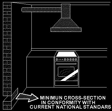
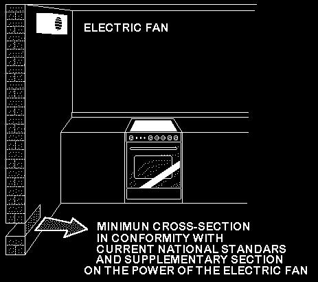
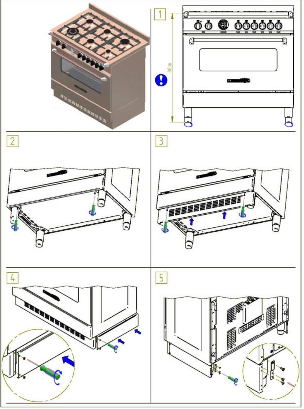
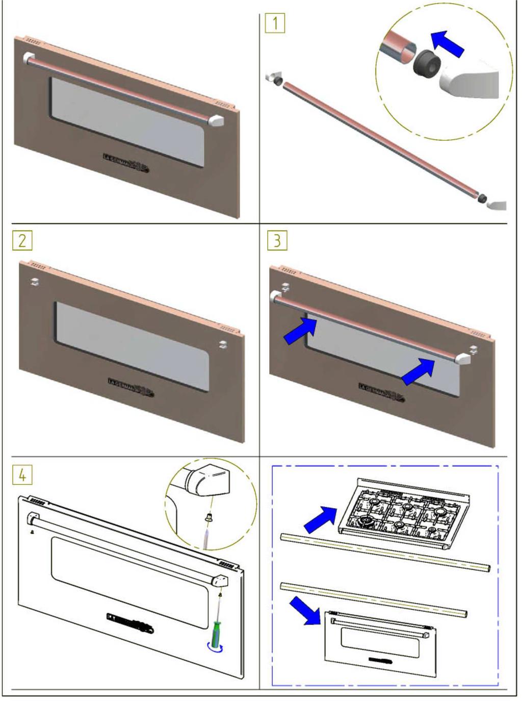
3 WARNING: the connection to the gas network must only use metal flexible pipes that conform with the national standards in force. IMPORTANT INFORMATION FOR INSTALLING THE APPLIANCE The cooker can be installed separately, as a freestanding unit, on a plinth (Only for models with all electric ovens/grills), or between kitchen units or between a kitchen unit and the wall. If installing the appliance as a freestanding cooker, screw the height adjustable telescopic legs supplied to the base of the appliance. If installing the appliance on a plinth, screw the levelling feet supplied to the base of the appliance. This appliance is not connected to devices which exhaust combustion products. Special attention must be focused on the prescriptions described below regarding room aeration and ventilation. Any hanging cabinets installed above the work surface must be located at a distance of no less than 700 mm. This appliance is not intended to be operated by means of an external timer or separate remote-control system. NOT FOR USE IN MARINE CRAFT, CARAVANS OR MOBILE HOMES UNLESS EACH BURNER IS FITTED WITH FLAME SAFEGUARD. WHERE THIS APPLIANCE IS INSTALLED IN MARINE CRAFT OR IN CARAVANS, IT SHALL NOT BE USED AS A SPACE HEATER. WARNING: SERVICING SHOULD BE CARRIED OUT ONLY BY AUTHORISED PERSONNEL. DO NOT MODIFY THIS APPLIANCE. ROOM VENTILATION To ensure that the appliance operate correctly, the room where it is installed must be continuously ventilated. The room volume should not be less than 25 m³ and the quantity of air needed shall be based on the regular combustion of gas and on the ventilation of the room. Natural air will flow through permanent openings in the walls of the room to be ventilated: these openings will be connected with the outside environment and shall have a minimum cross-section defined by the current national standards regarding room ventilation (see Fig. 2). These openings shall be built so that they cannot be clogged. Indirect ventilation is also permitted by taking air from the rooms adjacent to the one to be ventilated. LOCATION AND AERATION The gas cooking appliances must always evacuate the combustion products by means of hoods connected to chimneys, flues or directly outside (see Fig. 3). If a hood cannot be installed, it is possible to use a fan installed on a window or directly facing outdoors, to be operated together with the appliance (see Fig. 4), provided that there is strict compliance with the ventilation regulations. HEIGHT-ADJUSTABLE FEET (figure.5) The feet are packed in the top box. The feet should be installed with the cooker close to its final installation position; the feet are not safe to move the cooker long distances. After unpacking the cooker, lift it with your foot, to fit the cooker feet in the bases at the bottom. Slowly lower the cooker so its weight is resting on the feet and on the assembly fixings. We recommend using a lifting device or pallet instead of tilting the cooker. INSTALLING THE TOEKICK PANEL (only available for some models) After installing the feet, install the cooker skirt as shown in the pictures in Figure 6 INSTALLING THE RISER Remove the 2 screws securing the hob at the rear, as shown in (figure 7) Put the upstand in place and secure at the bottom with the two screws, as shown in (figure 7) Secure the middle of the upstand using the screws provided with the upstand (figure 7) INSTALLING THE HOB RAIL AND OVEN HANDLE The handle is packed with the upstand. Assemble oven handle as shown in the pictures (8) 3
4 APPLIANCE GAS CONNECTION Before connecting the appliance to the gas network, make sure that the data on the label attached to the food warmer drawer or on the back of the cooker are compatible with what is indicated for the gas distribution network. A label attached to the last page of this handbook and in the food warmer drawer (or on the back) of the appliance indicates the appliance adjustment conditions: type of gas and operating pressure. IMPORTANT: This appliance must be installed in compliance with current national standards in force and used only in a well-ventilated room. This appliance shall be installed only by authorised persons and in accordance with the manufacturer's installation instructions, local gas fitting regulations, municipal building codes, electrical wiring regulations, local water supply regulations, AS/NZS Gas Installations General installations and any other statutory regulations. WARNING: It should be recalled that the appliance utilises a threaded 1/2" gas cylindrical male fitting according to UNI-ISO For ease of service, the cooker should be connected with a Flexible Hose, which complies with AS/NZS 1869 (AGA Approved), 10mm ID, class B or D, between 1-1.2m long and in accordance with AS5601 for a high level connection. WARNING: Ensure that the hose is not subjected to abrasion, kinking or permanent deformation and should be able to be inspected along its entire length. Unions compatible with the hose fittings must be used and connections tested for gas leaks. The fixed consumer piping outlet should be at approximately the same height as the cooker connection point, pointing downwards and approximately 200mm - 300mm in from the left hand side of the cooker. The hose should be clear of the floor when the cooker is in the installed position. A hose restraint chain should be anchored to the wall to prevent strain on the hose connections when the cooker is pulled forward. Fit the supplied gas connectors as shown in Fig. 9 for your installation gas type. The gas inlet has a 1/2" BSP male thread. When making the connection, take care not to apply excessive stress by counterbalancing tightening force. Ensure that the available gas supply is the same as the gas type label affixed near the gas connection point. If not, contact Bertazzoni Service Center for a Gas Conversion Kit. Natural Gas The natural gas regulator supplied must be fitted for natural gas. Ensure the arrow on the regulator points towards the direction of the gas flow. Commissioning Procedure - The test point pressure must be adjusted to 1.00 kpa with the Wok and Rapid Burners operating on maximum flame. Universal LPG (U-LPG) Fit the LPG test point assembly (supplied in the gas conversion kit). An AGA Approved gas regulator suitable for a supply pressure of 2.75kPa should be part of the gas tank supply. ANTI-TILTING CHAIN/HOSE RESTRAINING CHAIN If installing the cooker with a hose, a chain should be fitted by the installer within 50mm of the hose connection point to prevent strain on the hose when the cooker is pulled forward. The chain should restrict the appliance movement to no more than 80% of the hose length. After the chain is installed, check that there is no strain on the hose or gas connections when the cooker is pulled as far forward as the chain allows. The cooker is also supplied with two chains which are connected to the rear left and right of the appliance. The chains should be connected to the wall directly behind the chains as low as possible to prevent the appliance from tilting forward. If the appliance is installed between two cupboards, drill a Ø13mm hole on each side of the cupboards level with the anchor point of the chains. As you push the cooker back towards the wall, pass the chains through the holes and keep pulling the chains so that there is no slack behind the cooker when it is in its final position. Anchor the chains taught within each cupboard. Ensure the chain connections are strong enough to support the weight of the appliance and taught to prevent it from tilting forward. WARNING: In order to prevent accidental tipping of the appliance, for example a child climbing onto the open oven door, the stabilising means must be installed. Ensure the chains are correctly anchored to prevent the appliance from tilting forward and to prevent strain on the hose when the cooker is pulled forward. MAKE SURE THE ANTI-TILTING CHAINS ARE TAUGHT WHEN ANCHORED TO PREVENT THE APPLIANCE TILTING. 4
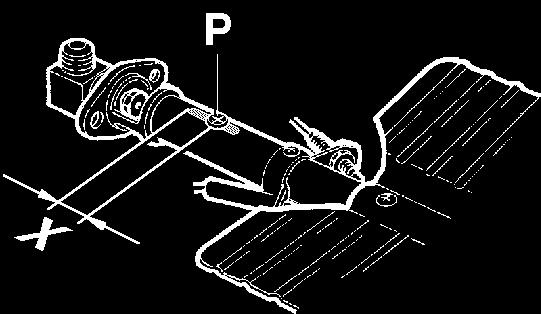
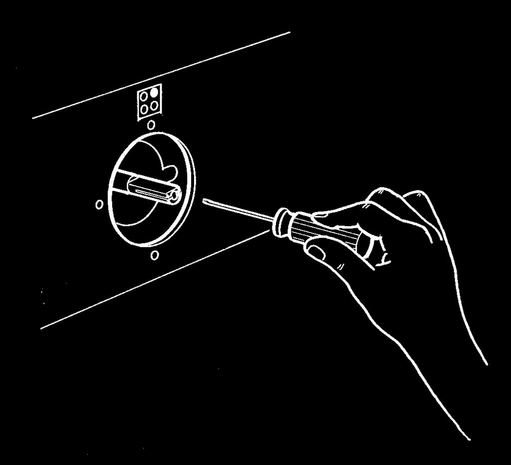
5 ADAPTATION TO DIFFERENT TYPES OF GAS FOR COOKER TYPE MKV Before performing any maintenance operation, disconnect the appliance from the gas supply and electricity network. REPLACING THE NOZZLES TO OPERATE WITH ANOTHER TYPE OF GAS FOR COOKER TYPE MKV: Follow the instructions below to change the burner nozzles on the work surface: 1) Pull out the plug from the electric outlet to avoid any type of electric contact. 2) Remove the grids from the work surface (Fig. 10). 3) Remove the burners (Fig. 10). 4) Unscrew the nozzles using a 7 mm spanner, and replace them (Fig.11) with those needed for the new type of gas according to what is indicated in Table 1. Follow the instructions below to change the oven burner nozzle: 1) Remove the oven level (Fig. 12). 2) Loosen the screw V and pull out the burner from the support being careful not to damage the ignition plug and the thermocouple (Fig. 13). 3) Unscrew the nozzle R (Fig. 13) using a 10 mm spanner and replace it with the nozzle needed for the new type of gas according to what is indicated in Table 1. WARNING: After completing the above-mentioned replacements, the technician must adjust the burners, as described in the paragraph below, seal any adjustment and pre-adjustment devices and apply the label on the appliance, to replace the existing one, corresponding to the new gas adjustment. This label is contained in the spare nozzle bag. Adaption to various types of gas Burners Gas type Pressure (kpa) Injector (mm) Mj/hr Small Natural Small U-LPG Medium Natural Medium U-LPG Large Natural Large U-LPG Wok Natural Wok U-LPG Oven Natural Oven U-LPG BURNER ADJUSTMENT 1)Primary air adjustment: Oven burner adjustment: follow the instructions below to adjust the primary air for the over burner: 1) Remove the oven bottom. 2) Loosen the screw P and adjust the position X of the Venturi cone (Fig. 14) according to the measurements indicated in table 2. TABLE N 2: Burner primary air regulation (indicative) BURNER Type of gas Oven (mm) Natural fully open Universal LPG fully open 2) Burner "MINIMUM" adjustment: Work surface burner adjustment: follow the instructions below to adjust the work surface burner minimum: 1) Light the burner and set the knob to the MINIMUM position (small flame). 2) Remove the knob of the valve that is press fit on the rod of that valve. 3) If the cooker is not equipped with safety valves on the surface burners, insert a small slotted screwdriver into the hole on the valve rod (Fig. 15) and turn the choke screw to the right or left until the burner flame is adjusted to minimum. If the cooker is equipped with safety valves, the choke valve is not located in the rod hole, but on the valve body (see fig. 16). 4) Make sure that the flame does not go out when switching quickly from the MAXIMUM to the MINIMUM position. Oven burner adjustment: follow the instructions below to adjust the minimum: 1) Light the burner setting the knob to the MAXIMUM position. 2) Close the oven door and operate the oven for at least 10 minutes. 3) Set the knob to the MINIMUM position (corresponding to 120 ) and then remove it. 5
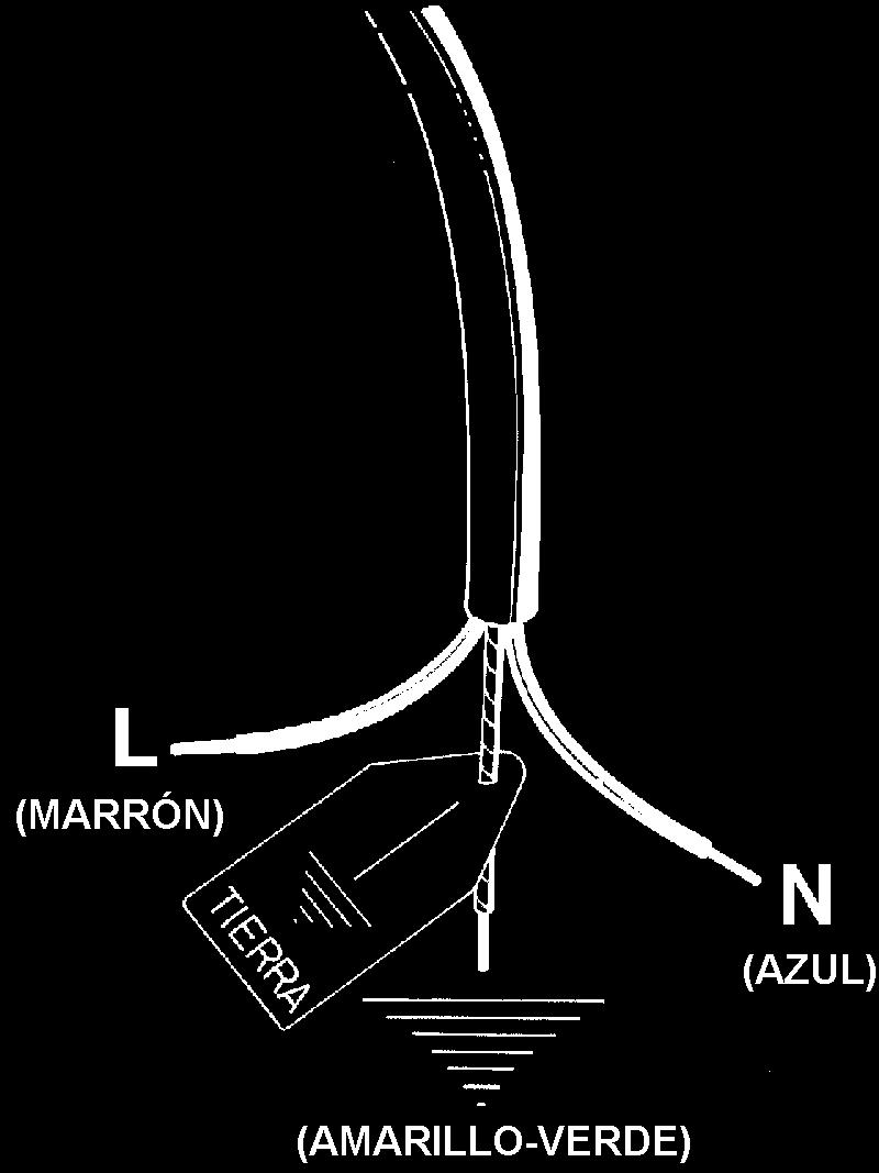
6 4) With a slotted screwdriver turn the choking screw (see figure 17) and, while observing the flame at the same time through the cooker porthole, evaluate the consistency of the flame so it remains on when switching quickly from the MINIMUM to the MAXIMUM position. WARNING: The above-mentioned adjustment should be made only with Natural gas burners, while for those operating with Universal LPG the screw must be locked at the end in a clockwise direction. The grill burner always operates at maximum and therefore no minimum adjustment is required. APPLIANCE ELECTRIC CONNECTION: The electric connection must comply with the current legal standards and regulations. Before making the connection, check that: - The system electrical rating and the current outlets are adequate for the maximum power output of the appliance (see the label applied to the bottom of the casing). - The outlet or the system is equipped with an efficient ground connection in accordance with the current legal standards and regulations. The company will not be responsible for the non-compliance with these instructions. When the connection to the power supply network is made using an outlet: - If the power cord is supplied without a plug, apply a standard plug that is suitable for the load indicated on the label. Connect the wires according to the diagram shown in FIG.18 and check that: letter L (phase) = brown wire; letter N (neutral) = blue wire; ground symbol = green-yellow wire; - The power cord must be positioned so that an overtemperature of 75 K will not be reached at any point. - Do not use reductions, adapters or splitters since they might cause false contacts and lead to dangerous overheating. When the connection is made directly to the electric network: - Use a device that ensures disconnection from the mains in which the contacts are opened to a distance that permits complete disconnection according to the conditions for over-voltage category III. - Remember that the ground wire must not be interrupted by the circuit-breaker. - As an alternative, the electric connection can also be protected by a high-sensitivity residual current circuit-breaker. - It is highly recommended to attach the special green-yellow ground wire to an efficient ground system. WARNING: If the power cord is replaced, the ground wire (yellow-green) connected to the terminal, should be longer than the other wires by about 2 cm. WARNING: If the supply cord is damaged, it must be replaced by the manufacturer or its service agent or a similarly qualified person in order to avoid a hazard. For New Zealand - This cooking range must be connected to the supply by a supply cord fitted with an appropriately rated plug that is compatible with the socket-outlet fitted to the final sub-circuit in the fixed wiring that is intended to supply this cooking range. TABLE N 3 : TYPES OF POWER CORDS Work surface operation Oven operation Cross section 230V ~ Only gas burner Gas oven / Electric grill 3x1mm² Ventilated Electric Oven 3x1,5mm² BEFORE LEAVING When the installation is complete, always check for gas leaks using a soapy solution. Never use a flame to make this check. Ignite all burners on high flame to ensure correct operation of gas valves, burners and ignition. Turn gas taps to low flame position and observe each burner to ensure they ignite completely at all ports and that the flame is stable. Conduct these checks for each burner individually and concurrently. When satisfied with the appliance, please instruct the user on the correct method of operation. In case the appliance fails to operate correctly after all checks have been carried out, please call the Bertazzoni Service Center. APPLIANCE MAINTENANCE ATTENTION: IMPORTANT WARNINGS For cookers resting on a base ATTENTION: If the cooker rests on a base, take the measures necessary to prevent the cooker from sliding along the support base. For cookers with glass covers ATTENTION: Before opening the appliance s glass cover, carefully remove all liquid residues from the top of it. ATTENTION: Before closing the appliance s glass cover, make sure that the work surface has cooled. For cookers with electric ovens During use, the appliance becomes hot. Care should be taken to avoid touching heating elements inside the oven. 6
7 For cookers with electric ovens WARNING: Accessible parts may become hot during use. To avoid burns, young children should be kept away. For the food warmer compartment (or drop leaf in our case) ATTENTION: The internal parts of the food warmer can become hot during use. For glass doors Do not use harsh abrasive cleaners or sharp metal scrapers to clean the oven door glass since they can scratch the surface, which may result in shattering of the glass. Do not use steam cleaners to clean the appliance. NOTE: various parts of the cooker heat up reaching temperatures which seem very high but which are actually fully within safety limits. According to these limits: 1) With the oven on at 200 C for 1 hour, front acce ssible parts which cannot be grasped, can reach the following temperatures: - Control panel: Tmax = Room Temperature +60 C - Glass of the oven door: Tmax = Room temperature+60 C - Metal part of the oven door: Tmax = Room temperature+45 C 2) With the oven on at 230 C for 1 hour, the parts which can be grasped, can reach the following temperatures: - Plastic knobs: Tmax = Room temperature+60 C - Metal oven door handle: Tmax = Room temperature+35 C where the room temperature is the temperature in C of the place where the appliance is installed. REPLACING PARTS Before performing any maintenance operation, disconnect the appliance from the gas supply and electricity network. To replace parts such as knobs and burners, just remove them from the seats without disassembling any part of the cooker. To replace parts such as nozzle supports, valves and electric components follow the procedure described in the burner adjustment paragraph. To replace the valve or the gas thermostat, it is also necessary to disassemble the two rear gas train brackets, loosening the 4 screws (2 per bracket) that attach it to the rest of the cooker and, unscrew the nuts that attach the front burner valves to the control support, after removing all the knobs. To replace the gas or electric thermostat, also disassemble the rear cooker guard, loosening the relative screws, to be able to pull out and reposition the thermostat bulb. To replace the oven bulb, just unscrew the protection cap that projects out inside the oven. (Fig.19) WARNING: Ensure the appliance is switched off before replacing the lamp to avoid the possibility of electric shock. WARNING: The power cord supplied with the appliance is connected to that appliance with a type Y connection (in compliance with standards EN , EN and subsequent amendments) for which it must be replaced by the manufacturer or its service agent or a similarly qualified person in order to avoid a hazard. If the power cord becomes worn or damaged, replace it based on the information reported in table 3. WARNING: If the power cord is replaced, the installer shall ensure that the ground cable is longer than the phase cables and also shall comply with the warnings regarding the electric connection. To replace the power cable, lift the terminal board s cover and replace the cable. USE AND MAINTENANCE MANUAL WARNING: This appliance is not intended for use by persons (including children) with reduced physical, sensory or mental capabilities, or lack of experience and knowledge, unless they have been given supervision or instruction concerning use of the appliance by a person responsible for their safety. WARNING: Children should be supervised to ensure that they do not play with the appliance. DO NOT USE OR STORE FLAMMABLE MATERIALS IN THE APPLIANCE STORAGE DRAWER OR NEAR THIS APPLIANCE. DO NOT SPRAY AEROSOLS IN THE VICINITY OF THIS APPLIANCE WHILE IT IS IN OPERATION. DO NOT STORE OR USE FLAMMABLE LIQUIDS OR ITEMS IN THE VICINITY OF THIS APPLIANCE. WHERE THIS APPLIANCE IS INSTALLED IN MARINE CRAFT OR IN CARAVANS, IT SHALL NOT BE USED AS A SPACE HEATER. WARNING: SERVICING SHOULD BE CARRIED OUT ONLY BY AUTHORISED PERSONNEL. DO NOT MODIFY THIS APPLIANCE. 7
8 TABLE 4 GAS BURNER DIMENSION Burner Dimension (mm) Auxiliary Ø 50 Semi-rapid Ø 70 Rapid Ø 95 Ultra-rapid Ø 130 CONTROL PANEL DESCRIPTION On the control panel, small symbols show the function of each knob or key. Here as follows are the several controls that a cooker can have: the symbol shows the disposition of burners on the worktop, the full dot identifies the burner in object (in this case the front left burner). the symbol shows the running of any oven (gas oven with electric grill, static oven, 9 positions switch) the symbol shows the electric thermostat for electric fan oven USING BURNERS A diagram is etched on the control panel above each knob which indicates which burner corresponds to that knob. The burners can be ignited in different ways depending on the type of appliance and its specific characteristics: - Manual lighting (it is always possible even when the power is cut off): Turn the knob anticlockwise that corresponds to the burner selected, setting it to the MAXIMUM position at the etched star (large flame Fig.20) and place a lit match up to the burner. - Electric ignition: Turn the knob counterclockwise that corresponds to the burner selected, setting it to the MAXIMUM position (large flame Fig. 20) and keep on pressing the knob in correspondence of the ignition symbol marked with a star (for cookers equipped with ignition trough knob) or press the ignition button marked with a star and release it as soon as the burner has ignited. - Burner ignition equipped with safety device (thermocouple)(fig.21): Turn the knob anticlockwise that corresponds to the burner selected, setting it to the MAXIMUM position at the etched star (large flame Fig. 20), press the knob and activate one of the above-mentioned ignition devices. Once ignited, keep pressing the knob for about 10 seconds to allow the flame to heat the thermocouple. If the burner goes out after releasing the knob, repeat the entire operation. Note: It is recommended not to try to ignite a burner if the relative flame cap is not in the correct position. If the flame does not light after the first attempt, wait 5 minutes for the gas to dissipate before attempting to re-light the burner. Tips for using burners correctly: - Use suitable pots for each burner (see tab. 5 and Fig. 23). - When the liquid is boiling, turn the knob to the MINIMUM position (small flame Fig. 20). - Always use pots with a cover. TABLE N 5 BURNER PAN DIAMETER recommended (cm) Auxiliary Semi-rapid Rapid Double ring ATTENTION: Use pots with a flat bottom NOTE: use flat-bottomed pans NOTE: after cleaning the burners, make sure the caps A and flame spreader heads B are positioned properly as shown in figure 22 and are not positioned as also shown in figure 22. WARNING: If the power is cut off, the burners can be lit with matches. When cooking foods with oil and fat, which are very flammable, the user should not leave the appliance unattended. If the appliance is equipped with a glass cover, such a cover may break when heated. Turn off all burners before lowering the cover. Do not use sprays near the appliance when it is being used. When using the burners, make sure that the handles of the pots are correctly positioned. Keep children away from the appliance. If equipped with a cover, before being closed, any food deposits should be cleaned off the built-in surface. NOTE: The use of a gas cooking appliance produces heat and humidity in the room where it is installed. Therefore, proper aeration in the room is needed while ensuring that natural ventilation openings remain unobstructed (Fig.2) and activating the mechanical aeration device/exhaust hood or electric fan (Fig. 3 and Fig. 4). Intensive and continuous use of the appliance may require additional aeration, for example by opening a window, or more efficient aeration by increasing the power of the mechanical exhauster, if installed. 8
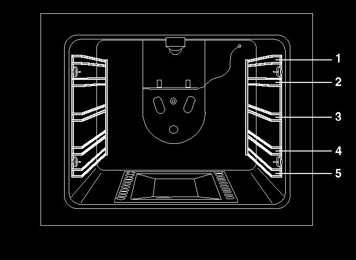
9 USING THE GAS OVEN All the gas oven cookers are equipped with a thermostat and safety device to adjust the cooking temperature. The oven temperature is set by turning the knob counterclockwise to match the indicator with the temperature selected. The gas oven can be combined with a gas grill or an electric grill. See the specific pages for use information. Operating the fan of the oven by means of the appropriate switch situated on the control panel, the circulation of warm air guarantees a uniform heat distribution. The preheating of the oven can be avoided. However for delicate baking, it is preferable to warm the oven before introducing the baking-pan. The baking system with the fan convection changes in part the various traditional baking notions. When roasting meat it is not necessary to turn the meat any more and for a roast on the spit, it is not indispensable to use the spit-roaster, but is sufficient to put the meat directly on the grate. With the use of the fan gas oven, the baking temperatures are slightly lower of about C compared to those in use with the traditional gas oven. The oven can also be used in a traditional way, for foods requiring heat from the bottom, e.g. pizza. WARNING: If the burner flames are extinguished accidentally, turn off the control knob and do not try to relight the oven until after at least 1 minute. TABLE N 6 THERMOSTAT SETTING TEMPERATURE C The oven burner can be ignited in different ways: - Manual lighting (it is always possible even when the power is cut off): To light the oven, open the oven door and turn the knob so the no. 8 on the scale matches the indicator (fig.24). At the same time put a lit match next to the ignition tube that is visible on the oven level (fig.25). Then press the thermostat knob (this makes the gas start to flow) and keep it pressed, after the burner has been completely lit, for 10 seconds. Release the knob and make sure that the burner remains on, otherwise repeat the operation. - Electric ignition (only for the models equipped with this device): In this case, first open the oven door, then turn the knob to the maximum temperature setting (number 8). Then press the thermostat knob (models with ignition trough knob). Wait about 10 seconds after the burner has been completely lit and then release the knob. Make sure that the burner remains on, otherwise repeat the operation. As for cookers without ignition trough knob, press the thermostat knob and the key with the spark symbol, wait about 10 seconds after the burner has been completely lit and then release the knob. Make sure that the burner remains on, otherwise repeat the operation. The ignition device should not be used for more than 15 seconds. If after that period the burner still has not been lit, do not use the device and open the door of the room or wait at least 60 seconds before trying to light the oven again. WARNING: when trying to light the oven, the door must always be open. When using the oven, leave the cooker cover open to prevent it from overheating. NOTICE: when using the oven for the first time it should be operated for minutes at a temperature of about 250 without cooking anything inside in order to eliminate any moisture and odours from the internal insulation. During normal oven use, after lighting the burner and setting the desired temperature, wait about 15 minutes before putting in any food to preheat the oven. The oven is equipped with 5 guides at different heights level (fig.26a) which can be used to insert shelves or the tray. To keep the oven as clean as possible it is recommended to cook meat on the tray or on the shelf that has been inserted inside the tray. The table below lists the general cooking times and the position of the tray for different types of foods. Personal experience will help to determine any variations in the values reported in the table. In any case, it is recommended to follow the instructions of the specific recipe being used. Temperatures between brackets are referred to the use of oven with fan assisted gas. TABLE N 7 GAS OVEN COOKING TABLE TEMP C HEIGHT MINUTES MEAT PORK ROAST 220 (210) BEEF ROAST (YOUNG STEER) 250 (240) BEEF ROAST 240 (230) VEAL ROAST 220 (210) LAMB ROAST 220 (210)
 4 40-45 FISH 200-225 (190-215) 3 15-25 PASTRY FRUIT PIE 200 (210) 3 35-40 TEA CAKE 190 (180) 3 50-55 BRIOCHES 175 (165) 3 25-30 SPONGE CAKE 235 (225) 3 20 RING CAKE 190 (180) 3 30-40 SWEET PUFF")
 4 5 BREAD 220 (210) 3 30 PIZZA 220 (210) 3 20 USING THE 2+0 CHANGE-OVER SWITCH (figure 29) (only for gas ovens) The 2+0 change-over switch used for gas oven models.")
10 ROAST BEEF 230 (230) ROAST HARE 235 (225) ROAST RABBIT 220 (210) ROAST TURKEY 235 (225) ROAST GOOSE 225 (215) ROAST DUCK 235 (225) ROAST CHICKEN 235 (225) FISH ( ) PASTRY FRUIT PIE 200 (210) TEA CAKE 190 (180) BRIOCHES 175 (165) SPONGE CAKE 235 (225) 3 20 RING CAKE 190 (180) SWEET PUFF PASTRIES 220 (210) 3 20 RAISIN LOAF 220 (210) STRUDEL 180 (170) SAVOIA COOKIES 190 (180) 3 15 APPLE FRITTERS 220 (210) 3 20 SAZOIARDI SANDWICH 220 (210) TOAST SANDWICH 250 (240) 4 5 BREAD 220 (210) 3 30 PIZZA 220 (210) 3 20 USING THE 2+0 CHANGE-OVER SWITCH (figure 29) (only for gas ovens) The 2+0 change-over switch used for gas oven models. the symbol is for oven fan and light operation, to use the gas oven or grill with fan. the symbol is for turning on the oven light USING THE ELECTRIC THERMOSTAT FOR MULTI-FUNCTION COOKERS The thermostat provided in every model keeps the temperature inside the oven constant at a temperature range from 50 C to 250 C. Turn the knob clockwise (Figure 28),to align the selected temperature on the metal ring with the indicator printed on the front panel. An orange light shows the thermostat is working and goes off when the oven temperature has exceeded the selected temperature by 10 C and comes on when the selected temperatures drops below 10 C. The thermo stat can operate the oven heating elements only if the switch is in one of the heating element operating modes. If the switch is set to 0, the thermostat will not operate the heating elements. USING THE 9-SETTING MULTI-FUNCTION OVEN SELECTOR The 9+0 setting change-over switch for multi-function ovens is used to control, along with the thermostat, the fan motor and heating elements. To turn on the elements, both the knob on the 9+0 switch and thermostat need to be turned; if only one knob is turned, the oven will not work and only the light or fan motor will come on. The electric oven has 4 heating elements: a bottom element, two top elements and a round element; turn the change-over switch knob (Figure 31) to enable the heating element matching the symbol on the metal ring. However to operate this element, you need to turn the thermostat knob until the orange light shows the element has come on. If you position the change-over switch to any one of the nine operating modes, the relative heating element is enabled as well as the oven light. After the temperature and heating elements to operate have been selected, the oven heating elements are operated by the thermostat, so it is normal for the orange light to come on and off during operation. To turn off the electric oven, set the change-over switch knob to 0 to prevent the thermostat operating the heating elements. The heating elements will be disabled, but the fan motor and oven light can be turned on from the changeover switch. The switch has 9 settings, for 9 different types of oven operation: - the symbol indicates that only the oven light is on; - the symbol indicates that the 1300W bottom heating element and external 900W top heating element are on; - the symbol indicates that only the external 900 W top heating element is on; 10
; - the symbol indicates that the external 900W top heating element, the 2000W grill heating element and")

11 - the symbol indicates that only the 1300W bottom heating element is on; - the symbol indicates that only the 2000 grill heating element is on (see specific section); - the symbol indicates that the external 900W top heating element and 2000W grill heating element are on (see specific section); - the symbol indicates that the external 900W top heating element, the 2000W grill heating element and fan motor are on (see specific section); - the symbol indicates that the 2400W round heating element and fan motor are on; - the symbol indicates that only the fan motor is on. When the knob is turned to one of these nine positions, the oven light is always on, to indicate tension inside the oven. USING THE ELECTRIC OVEN WITH NATURAL CONVECTION When using the oven for the first time, leave it on for maximum 30 minutes at a temperature of 250, t o eliminate smell from the internal seals. During normal use, select the cooking temperature using the thermostat knob, then wait for the orange light to go off before putting foods in. The oven has 5 grooves at different heights (Figure 26a) for fitting racks or trays. To prevent getting the oven too dirty, meat should be cooked on a tray or rack placed in the tray. TABLE 8 COOKING TIMES FOR ELECTRIC OVENS WITH NATURAL CONVECTION TEMP C HEIGHT MINUTES MEAT ROAST PORK 225 3/ ROAST STEER 225 3/ ROAST OX 250 3/ ROAST VEAL 225 3/ ROAST LAMB ROAST BEEF 230 3/ ROAST HARE 250 3/ ROAST RABBIT ROAST TURKEY ROAST GOOSE ROAST DUCK 250 3/ ROAST CHICKEN 250 3/ FISH CAKES AND PASTRIES FRUIT CAKE SANDWICH CAKE BRIOCHES SPONGE CAKE DOUGHNUTS PUFF PASTRY GRAPE TART STRUDEL SAVOYARD BISCUITS APPLE FRITTERS PUDDING WITH SAVOYARD BISCUITS TOASTED SANDWICH BREAD PIZZA USING THE ELECTRIC OVEN WITH FAN When using the oven for the first time, leave it on for maximum 30 minutes at a temperature of 250, t o eliminate smell from the internal seals. Before cooking foods, make sure the oven reaches the selected temperature and the orange light is off. This type of oven has a round heating element inside, where the fan for forced air circulation in a horizontal direction is positioned. Based on this operating principle, a fan oven can be used for different kinds of cooking at the same time, without 11
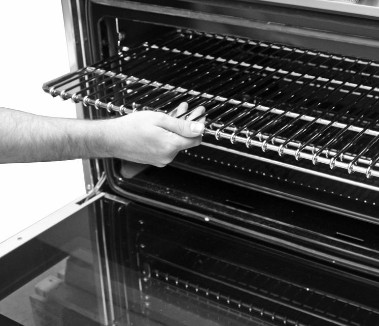
12 changing the taste of the food. A few models are fitted at the rear with a removable metal filter that retains grease when cooking roasts. This filter should be cleaned regularly with soapy water to remove the grease and rinsed thoroughly. To remove the metal filter, apply gentle pressure upwards on the tab, indicated by the arrow. The circulation of hot air ensures that heat is evenly distributed. It is not necessary to preheat the oven, however in the case of delicate baking, the oven should be preheated before putting in baking trays. The convection fan cooking system changes to some extent concepts about traditional cooking. Meat does not have to be turned during cooking and a spit does not have to be used for rotisserie roasting. The meat can be simply put on the rack. TABLE 9 COOKING TIMES FOR ELECTRIC FAN OVENS TEMP C HEIGHT MINUTES MEAT ROAST PORK ROAST STEER ROAST OX ROAST VEAL ROAST LAMB ROAST BEEF ROAST HARE ROAST RABBIT ROAST TURKEY ROAST GOOSE ROAST DUCK ROAST CHICKEN FISH CAKES AND PASTRIES FRUIT CAKE SANDWICH CAKE BRIOCHES SPONGE CAKE DOUGHNUTS PUFF PASTRY GRAPE TART STRUDEL SAVOYARD BISCUITS APPLE FRITTERS PUDDING WITH SAVOYARD BISCUITS TOASTED SANDWICH BREAD PIZZA POSITIONING THE OVEN TRAYS & SHELVES The Grill Tray or Oven Shelf can be located in any of the four height positions in the oven (See Fig. 26a). Refer to the Oven Cooking Tables for the recommended shelf position. When fitting the trays or shelves, ensure they are fitted between the two wires that are closest together (See Fig. 26b). Oven Shelves have a stop so that they are not fully withdrawn by accident. To fully remove the Oven Shelves, lift the front of the shelf slightly and withdraw fully from the oven. (See Fig. 26d) Note that the Grill Tray does not have a stop position and can be fully withdrawn without interruption, so be careful not to accidentally fully withdraw the tray. To remove the Oven Shelf Support, remove the top and bottom screws shown in Fig 26c and then pull the support from the holes in the rear oven wall. Repeat for opposite side. Replace in reverse procedure. USING THE STATIC ELECTRIC GRILL The electric grill can be combined with the gas or electric oven. With a gas oven + electric grill combination, the grill is operated from the oven thermostat knob. The electric grill for gas oven cookers has a 2500W rating. IMPORTANT: When using the electric grill in electric oven cookers, do not turn the thermostat knob to more than 150 C to prevent overheating the oven front; t he oven has been designed for closed-door grilling. Grilling on the rack: In this case, the rack should be put at level 1 or 2, placing foods on top of the rack and a drip tray below. Turn on the grill heating element, setting the thermostat to the relative position. IMPORTANT NOTE: the oven door must be kept closed when grilling using the static electric grill. WARNING: during use the appliance gets very hot. Do not touch the heating elements inside the oven. WARNING: Accessible parts may become hot when the grill is in use. Children should be kept away. 12
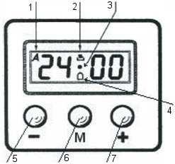
13 USING THE ELECTRIC GRILL WITH FAN The electric grill with fan is a special function for optimal grilling, with the oven rack at an intermediate position and the drip tray below. With gas oven cookers with electric grills, set the thermostat to the grill symbol and the 2+0 change-over switch to the position to turn on the 1500W grill heating element and fan motor. With cookers with a 9-setting change-over switch, set the 9+0 switch to the relative position and the electric thermostat to the temperature required, to turn on the grill heating element and fan motor. IMPORTANT: When using the electric grill with fan, do not turn the thermostat knob to not more than 175 C (between 150 and 200 C) to prevent overheating the oven front; the oven has been designed for closed-door fan grilling. USING THE THERMOMETER Figure 30 The cooker is fitted with a device to measure the temperature in the middle of the oven. This lets you check the temperature inside the oven and adjust food cooking temperatures more accurately. ELECTRIC OVEN When you turn on the oven, the orange light comes on to indicate that the heating elements are working: The thermometer dial will start to move towards the set temperature. The orange light will keeping coming on and off, indicating that the heating elements are working to maintain the temperature inside the oven. The light may go off for a few minutes before the thermometer has reached the temperature required. This is normal, because operation of the heating elements is regulated so that heat is distributed properly inside the oven. Heat is optimally distributed inside the oven when the thermometer dial has stopped. If the oven temperature drops or goes up, the thermometer dial will follow these variations in the same way. When the oven is turned off, the temperature on the thermometer will slowly drop until it reaches room temperature. NOTE: The temperatures on the knob are indicative. Follow the thermometer temperature for cooking. GAS OVEN When the oven is turned on, the burner will start working at the maximum and the thermometer dial will start to move towards the set temperature. The flame may die down before the thermometer has reached the temperature required. This is because burner power is reduced so that heat can be evenly distributed inside the oven. Heat is optimally distributed inside the oven when the thermometer dial has stopped. When the oven is turned off, the temperature on the thermometer will slowly drop until it reaches room temperature. NOTE: The Thermostat Position and Oven Temperature correspondence in table no. 6 is indicative and depends on various factors such as the type of gas and supply pressure. Follow the thermometer temperature for cooking. NOTE: it is normal to record different temperatures from those indicated on the panel thermometer, when you measure the temperature in the middle of the oven using a different thermometer. The temperature indicated by the thermometer is the mean temperature inside the oven and does not indicate the temperature of any single point. 3 KEYS ELECTRONIC PROGRAMMER (fig.33) The first start up The numbers and the A letter on the display are blinking when the oven is switched on for the first time, or after a power cut: the appliance cannot be operated in this condition. To set the hour and/or to enable the appliance to operate press the M key for at least 2 seconds: the A letter turns off and the numbers now are steady on the display. The dot (3) starts blinking: press the - or + key to set the hour. The hour is accepted by the programmer just few second after having released the key. N.B. the appliance can be correctly used for coking only when you will see on the display the symbol (2). The symbols on the display: 1 A* Automatic programme is working. (* in some models there is the writinq 'Auto' instead of A). 2 The appliance is ready for manual use (not automatic). 3 When blinking, the programmer is in setting hour mode. 4 Timer set. 5 - Decreasing numbers when setting the timer. Also for choose your desired sound level ( 3 levels available). 6 M "Mode" kev to access the programming options of the programme. 7 + Increasing numbers when setting the timer. 13
14 Timer The purpose of the timer is just of a sound signal, which can be set for a max time of 23h59min. once elapsed the set time, the (4) symbol turns off and a sound signal is heard; this sound set off automatically in 7min, or you can stop it by pressing any key of the programmer. To set the timer press the M key for 2 seconds, or anyway just to see the (4) symbol blinking. Set the timer by using the + or - keys. Release the + or - key when you have matched your desired time. In a few seconds the current time appears on the display together with the ) symbol. The countdown starts immediately from now on. Semi-automatic cooking Cooking time: Once having selected a coking function and set the desired temperature, press the M key for a 2 seconds time to access the programming mode. The (4) symbol appears. Release and press again the M key. On the display, the A symbol starts blinking and the " dur " writing appears on the display, then it changes to O' 00. Set the cooking time with the - or + keys. (max available time: 10h). The selected time is automatically processed by the programmer in a few seconds, or you can also touch the M key many times just to see again the current time. The A and (2) symbols will be on the display. Once the set cooking time is finished, a sound will be heard and the oven automatically switches off. Please see the following paragraphs about how to disable the sound alarm and restarting the oven. End of cooking once having selected a cooking function and set the desired temperature, touch the M key to access the programming mode for at least 2 sec. the ) symbol switches on. Release and touch again the M key. On the display the A symbol starts blinking and the writing "dur" appears. Touch again the M key. On the display the writing "End" appears. The last one changes few seconds after with the symbol Set the end of cooking time with the keys - or +. (maximum available time: 10hOOm). The selected time is automatically processed by the programmer in a few seconds, or you can also touch the M key many times just to see again the current time. The cooking immediately starts, while on the programmer display the current time is shown again in a few seconds. The A and (2) symbols will be on the display. Once the set end of cooking time is finished, a sound will be heard and the oven automatically switches off. Please see the following paragraphs about how to disable the sound alarm and restarting the oven. Automatic cooking Set a cooking time following the instructions on the cooking time paragraph, then set the end of cooking time following the instructions on the previous paragraph. (Max available end of cooking time 24h). The oven automatically switches on at a determined time which is the difference between the end of cooking time and the cooking time. During the waiting time before cooking, which goes from the oven start to the heating, on the display appears the A symbol to show that an automatic program is on and the current time. The oven on is marked by the (2) symbol. Once the set end of cooking time is finished, a sound will be heard and the oven automatically switches off. Please see the following paragraphs about how to disable the alarm and restarting the oven. How to disable the sound alarm: To disable the sound just touch one of the keys. Operating again the oven Once a semi-automatic or automatic cooking has expired, on the display appear the current time and the blinking A symbol. In this condition, the heating elements and the light bulb of the oven are disabled. To enable again the oven, just touch and keep the M key up to see the symbol (2) on the display and the A symbol disappears. OTHER FUNCTIONS How to delete a cooking time (semi-automatic or Automatic) To delete a semi-automatic or automatic cooking program, with the A symbol on, touch together the - and + keys for at least 2 seconds or anyway up to see the (2) and the disabling of A symbol. How to delete the countdown timer To delete the counting of the timer, which symbol is ) t touch the M key for at least 2 seconds or anyway up to see the ) symbol blinking. Touch together the - and + keys. Checking the function settings The set or remaining time of every cooking function of the programmer can be recalled to the display by entering in program mode with the M key. Touch and keep the M key for almost 2 seconds or anyway up to see the (4) symbol. The remaining time appears on the display, or a series of zero numbers if the timer is disabled. Touch again the M key. On the display appears the "dur" writing, then alternately the remaining time or a series of zero number (disable timer). By touching again the M key, the end of cooking time appears together with the "End" writing. 14
15 How to change the current time or the sound level With the programmer in standard mode, the (2) symbol is on, touch together the - and + keys for at least 2 seconds or anyway up to see the dot (3) blinking. To update the hour on the display: touch the + or - keys. To change the sound level: touch the M key. On the display appears the writing: Ton.. followed by a number. Select with the - key your favourite sound level. Note: number 1 is referred to the highest sound level. The available levels are 3. Attention: Power cut causes the loss of any program, even the clock; that means the programmer will have to be set again. Mains frequency detection 3 KEYS ELECTRONIC CLOCK (FIG. 33) At power on mains frequency is determined. When the timer is connected to 60Hz, the Celsius symbol is flashing during start-up. Power On At power on, the relay contact is opened. The display and AUTO symbol flashes and time of day starts from 0:00. Power on state with flashing daytime remains until time of day is set. Setting Time of Day Press PLUS and MINUS button simultaneously. At Power On, also MODE button is possible. Time of day can be set with PLUS or MINUS, while the colon between hours and minutes is flashing. Quick setting mode starts when PLUS or MINUS is held for more than 1 second. If daytime setting mode is selected while an automatic program is active, the automatic program is cancelled. The Buzzer The buzzer interval alarm signal sounds if minute minder has reached the end time. The signal can be switched off by pressing any key or by passing the signal duration limit. Changing the Buzzer frequency First press Plus and Minus simultaneously (menu far editing the time) and then Mode for selecting the menu far changing the buzzer frequency. While the text tonx is visible the buzzer signal frequency can be changed by touching Minus repetitively. Note: If the touch pad is inactive, a visual alarm will only be reset when a valid key combination is pressed far more than 2 seconds. Clearing Programs and Manual function The duration of the minute minder can be cleared by a) "clear Function": First select minute minder program, then press PLUS and MINUS button simultaneously. after this clear the display returns from adjustment mode to time of day immediately. b) Back counting of duration to zero. The timer remains in adjustment mode. Minute Minder While minute minder mode is selected, the Bell symbol flashes and the display reads the remaining time in hours and minutes, only if the last minute is counting down the remaining seconds are displayed. An active minute minder program is indicated by the statically illuminated Bell symbol. If alarm time has finished, an acoustic interval signal sounds and the Bell symbol flashes. The minute minder program runs independently of other programs. Key Lock After power on reset or when no key is pressed for 7 seconds, the key look function is activated. Pressing a valid key or key combination for 2 seconds or more will deactivate the key lock. USING THE SELF-CLEANING OVEN On models which have this device, the self-cleaning oven differs from normal ovens because the inner surfaces are coated with a special micro-porous enamel that absorbs and eliminates grease residues during cooking. If liquid grease is released, self-cleaning is not sufficient, so wipe the grease stains with a damp sponge and then heat the oven to the maximum temperature, wait for it to cool down and wipe again with a damp sponge. 15
16 ABNORMAL OPERATION Any of the following are considered to be abnormal operation and may require servicing: Yellow tipping of the burner flame. Burners failing to remain alight. Sooting up of cooking utensils. Burners extinguished by cupboard doors. Burners not igniting properly. Gas valves, which are difficult to turn. In case the appliance fails to operate correctly, contact Bertazzoni Service Center. CLEANING THE APPLIANCE Before any cleaning, unplug the appliance and turn off the gas tap. Do not use steam cleaners to clean the appliance Cleaning the hob: Clean the burner heads, enamelled steel pan supports, enamelled caps and flame spreaders regularly using warm soapy water. Rinse and dry well. Use a cloth to wipe away any liquids spilt from pans. If the gas tap does not open or close easily, do not force it, but seek technical assistance immediately. Cleaning enamelled parts: Clean enamelled parts frequently with soapy water, to keep their characteristics unaltered. Never use abrasive powders. Do not leave acid or alkaline substances (vinegar, lemon juice, salt, tomato juice, etc.) on enamelled parts, and clean the parts when still warm. Cleaning stainless steel parts: Clean with soapy water then dry with a soft cloth. Use special stainless steel cleaning products regularly to maintain the shine. Never use abrasive powders. Cleaning the flame spreaders: As the flame spreaders rest on the hob surface, to clean them, remove and wash with soapy water. Dry well and make sure the holes are not obstructed, before putting them back in position. Cleaning the oven glass panel: The oven glass panel can be removed. After opening the doors and blocking the hinges (figure 31) remove the glass panel (figure 32) and clean. Clean the panel when the oven is cold, using a damp cloth. Do not use abrasive products. Put the glass panel back, making sure the smooth part is on the outside and the printed part inside the oven door. Then release the hinges. Note: do not release the hinges if the glass panel is not fitted on the door. Cleaning inside the oven: To make heavy-duty cleaning easier, the door can be removed as follows. After opening the door and blocking the hinges (figure 31), put the door in a semi-open position and pull towards yourselves until it is released. To reassemble, proceed as above in reverse. The side racks can also be removed, by removing the nuts securing them to the oven. Cast iron or aluminium strip racks: Soft aluminium-bottomed pans are not recommended, to prevent leaving permanent marks on the rack surface which cannot be removed with normal washing. 16


17 Fig. 1 Fig. 2 Fig. 3 Fig. 4 Fig. 5 17
18 Fig. 6 18
19 Fig. 7 19
20 Fig. 8 20


21 Fig.9 fig.10 fig.11 fig12 fig13 fig14 fig15 T Fig. 16 Fig. 17 Fig.18 21


22 Fig.19 fig.20 Fig.21 Fig.22 Fig.23 fig.24 fig.25 22


23 fig.26a Fig.26b Fig.26c Fig.26d 23


24 fig.27 fig.28 fig.29 fig.30 Fig. 31 Fig. 32 Fig.33 24
INSTALLATION, MAINTENANCE AND USE INSTRUCTIONS FOR FREE-STANDING COOKERS 90x60 cm (type M9V) 60x60 cm (type M6V) VEF91EG VEF61EG
 60x60 cm (type M6V) VEF91EG VEF61EG") INSTALLATION, MAINTENANCE AND USE INSTRUCTIONS FOR FREE-STANDING COOKERS 90x60 cm (type M9V) 60x60 cm (type M6V) VEF91EG VEF61EG READ THE INSTRUCTION BOOKLET BEFORE INSTALLING AND USING THE APPLIANCE.
INSTALLATION, MAINTENANCE AND USE INSTRUCTIONS FOR FREE-STANDING COOKERS 90x60 cm (type M9V) 60x60 cm (type M6V) VEF91EG VEF61EG READ THE INSTRUCTION BOOKLET BEFORE INSTALLING AND USING THE APPLIANCE.
INSTALLATION, MAINTENANCE AND USE INSTRUCTIONS FOR FREE-STANDING COOKERS 90x60 cm (type M92/M92V)Dual oven
Dual oven") INSTALLATION, MAINTENANCE AND USE INSTRUCTIONS FOR FREE-STANDING COOKERS 90x60 cm (type M92/M92V)Dual oven READ THE INSTRUCTION BOOKLET BEFORE INSTALLING AND USING THE APPLIANCE. The manufacturer will
INSTALLATION, MAINTENANCE AND USE INSTRUCTIONS FOR FREE-STANDING COOKERS 90x60 cm (type M92/M92V)Dual oven READ THE INSTRUCTION BOOKLET BEFORE INSTALLING AND USING THE APPLIANCE. The manufacturer will
User Instructions FREESTANDING GAS RANGES BERTAZZONI
 User Instructions FREESTANDING GAS RANGES BERTAZZONI DIMENSIONS: 36 (915 mm)(w) x 253/16 (640 mm)(d) x36 (915 mm)(h) Models X365GGVX (X36 5 00 X) [M3W0GTU4X(2 or 5)A] Models X366GGVX (X36 6 00 X) [M3Y0GTU4X(2
USER MANUAL 900MM UPRIGHT COOKER BAF90EG
 USER MANUAL 900MM UPRIGHT COOKER BAF90EG 2 Baumatic BAF90EG 900mm Upright Oven User Manual Dear Customer, Congratulations on purchasing your new product from Home Appliances. To register your Parts and
INSTALLATION, MAINTENANCE AND USE INSTRUCTIONS FOR FREE-STANDING COOKERS 90x60 cm GIANT OVEN APPLY DATA LABELS
 INSTALLATION, MAINTENANCE AND USE INSTRUCTIONS FOR FREE-STANDING COOKERS 90x60 cm GIANT OVEN APPLY DATA LABELS 1 3100248 READ THE INSTRUCTION BOOKLET BEFORE INSTALLING AND USING THE APPLIANCE. It is important
PROF. RANGE COOKER MODEL: EPRC-A6456GE(SS) Owner s Manual Please read this manual carefully before operating your set. Retain it for future reference.
 Owner s Manual Please read this manual carefully before operating your set. Retain it for future reference.") PROF. RANGE COOKER MODEL: EPRC-A6456GE(SS) Owner s Manual Please read this manual carefully before operating your set. Retain it for future reference. Record model number and serial number of the set.
PROF. RANGE COOKER MODEL: EPRC-A6456GE(SS) Owner s Manual Please read this manual carefully before operating your set. Retain it for future reference. Record model number and serial number of the set.
Contents. Downloaded from manuals search engine
 Contents 1. INSTRUCTIONS FOR SAFE AND PROPER USE 6. INSTALLATION 8 3. DESCRIPTION OF CONTROLS 30 4. USE OF THE OVEN 35 5. AVAILABLE ACCESSORIES 36 6. COOKING HINTS 37 7. CLEANING AND MAINTENANCE 43 8.
operating & installation instructions SA20XMFR
 operating & installation instructions SA20XMFR Contents 1. INSTRUCTIONS FOR SAFE AND PROPER USE 26 2. INSTALLATION 28 3. DESCRIPTION OF CONTROLS 30 4. USE OF THE OVEN 35 5. AVAILABLE ACCESSORIES 36 6.
GAS COOKER GAS OVEN SERIES. Owner s Manual Please read this manual carefully before operating your set. Retain it for future reference.
 GAS COOKER GAS OVEN SERIES Owner s Manual Please read this manual carefully before operating your set. Retain it for future reference. Record model number and serial number of the set. See the label attached
Contents THESE INSTRUCTIONS ARE VALID ONLY FOR END USER COUNTRIES WHOSE IDENTIFICATION SYMBOLS APPEAR ON THE COVER OF THIS MANUAL.
 Contents 1. INSTRUCTIONS FOR SAFE AND PROPER USE 38. INSTALLING THE APPLIANCE 40 3. ADAPTATION TO DIFFERENT TYPES OF GAS 43 4. FINAL OPERATIONS 45 5. DESCRIPTION OF CONTROLS 47 6. USING THE COOKING HOB
Contents THESE INSTRUCTIONS ARE VALID ONLY FOR END USER COUNTRIES WHOSE IDENTIFICATION SYMBOLS APPEAR ON THE COVER OF THIS MANUAL.
 Contents 1. INSTRUCTIONS FOR SAFE AND PROPER USE 36. INSTALLING THE APPLIANCE 38 3. ADAPTATION TO DIFFERENT TYPES OF GAS 40 4. FINAL OPERATIONS 4 5. DESCRIPTION OF CONTROLS 44 6. USING THE COOKING HOB
SA990XR-8. operating and installation instructions
 SA990XR-8 operating and installation instructions Contents 1 INSTRUCTIONS FOR USE... 3 SAFETY PRECAUTIONS... 34 3 ENVIROMENTAL RESPONSIBILITY... 36 4 INSTALLATION... 37 5 DESCRIPTION OF CONTROLS... 39
BSM60SS / BSM60WH BUILT IN MULTI-FUNCTION ELECTRIC FAN OVEN. Instruction Manual
 BSM60SS / BSM60WH BUILT IN MULTI-FUNCTION ELECTRIC FAN OVEN Instruction Manual Please read these instructions carefully before use and retain for future reference CONTENTS Safety Instructions 2 Specifications
HG 675 CX 60 HG 675 CN 60 HG 675 CW 60
 HG 675 X 60 HG 675 CX 60 HG 675 CN 60 HG 675 CW 60 1 2 1. : 93/68: 90/396: 2006/95/CE: 2004/108/CE: - 1935/2004:. 2002/95/CE: RoHS 2.,.,,,,...,. (,..)..,,.,. ( ),,, ;,,.,.....,.,,,,,,...,. (..),,.,..,.,,,,
Instruction Manual for Electric Ovens OO757X OO986X
 Instruction Manual for Electric Ovens OO757X OO986X 1 2 DEAR CUSTOMER, We thank you and congratulate you on your choice. This new carefully designed product, manufactured with the highest quality materials,
OVENS AUS. Installation - Use - Maintenance. Oven models: 60cm Built in Ovens
 OVENS Installation - Use - Maintenance AUS Oven models: 60cm Built in Ovens 539.07.031 539.07.041 GENERAL INFORMATION Please read this booklet thoroughly before you use this appliance. It is important
PROF. RANGE COOKER MODEL: EPRC-9850FE/SS EPRC-9860E/SS. Owner s Manual Please read this manual carefully before operating your set.
 PROF. RANGE COOKER MODEL: EPRC-9850FE/SS EPRC-9860E/SS Owner s Manual Please read this manual carefully before operating your set. Retain it for future reference. Record model number and serial number
T-60cm-OVEN-SS T-60cm-OVEN-CM T-60cm-OVEN-BL
 T-60cm-OVEN-SS T-60cm-OVEN-CM T-60cm-OVEN-BL USER INSTRUCTIONS GENERAL WARNINGS Read carefully all the instructions contained in this booklet. It provides you with important information regarding the safe
Contents authorised persons
 Contents 1. INSTRUCTIONS FOR SAFE AND PROPER USE 4. INSTALLATION OF THE APPLIANCE 6 3. GAS CONNECTION 7 4. ADAPTATION TO DIFFERENT TYPES OF GAS 10 5. FINAL OPERATIONS 1 6. DESCRIPTION OF CONTROLS 14 7.
Contents THESE INSTRUCTIONS ARE VALID ONLY FOR END USER COUNTRIES WHOSE IDENTIFICATION SYMBOLS APPEAR ON THE COVER OF THIS MANUAL.
 Contents 1. INSTRUCTIONS FOR SAFE AND PROPER USE 44. INSTALLING THE APPLIANCE 46 3. ADAPTATION TO DIFFERENT TYPES OF GAS 50 4. FINAL OPERATIONS 5 5. DESCRIPTION OF CONTROLS 54 6. USING THE COOKING HOB
EV6004WH. Built-In Electric Oven User Manual
 EV6004WH Built-In Electric Oven User Manual ACKNOWLEDGMENT Thank you for purchasing our product. We hope you enjoy using the many features and benefits it provides. Before using this product please study
Electrical Double Oven
 0 0 0 Electrical Double Oven Operating & Installation Instructions -Please keep for future reference AE66DCW AE66DCA AE66DCSS Important - Please read these instructions fully before using These instructions
INSTRUCTIONS FOR USE. To make the most of your new oven, read the user's instructions carefully and keep them on hand for consultation in the future.
 INSTRUCTIONS FOR USE INSTALLATION...4 SAFEGUARDING THE ENVIRONMENT... 7 IMPORTANT NOTES... 7 BEFORE USING THE OVEN... 8 OVEN ACCESSORIES... 9 CARE AND MAINTENANCE... 10 TROUBLESHOOTING GUIDE... 12 AFTER
INSTRUCTION MANUAL BUILT-IN HOBS CIR900X
 INSTRUCTION MANUAL BUILT-IN HOBS CIR900X ENGLISH 3-19 Thank you for choosing our product. We advise you to read this manual carefully. It contains all necessary instructions for maintaining unaltered the
CTEC50WH CTEC60WH CTEC60BK OPERATING AND INSTALLATION INSTRUCTIONS OF ELECTRIC DOUBLE OVEN
 TM CTEC50WH CTEC60WH CTEC60BK EN OPERATING AND INSTALLATION INSTRUCTIONS OF ELECTRIC DOUBLE OVEN Dear Customer, Thank you for purchasing this Cooking Appliance. The safety precautions and recommendations
SAFEGUARDING THE ENVIRONMENT IMPORTANT NOTES BEFORE USING THE OVEN OVEN ACCESSORIES CARE AND MAINTENANCE TROUBLESHOOTING GUIDE AFTER SALES SERVICE
 INSTRUCTIONS FOR USE SAFEGUARDING THE ENVIRONMENT IMPORTANT NOTES BEFORE USING THE OVEN OVEN ACCESSORIES CARE AND MAINTENANCE TROUBLESHOOTING GUIDE AFTER SALES SERVICE To make the most of your new oven,
BSF60WH / BSF60SS BUILT IN ELECTRIC FAN OVEN. Instruction Manual. Please read these instructions carefully before use and retain for future reference
 BSF60WH / BSF60SS BUILT IN ELECTRIC FAN OVEN Instruction Manual Please read these instructions carefully before use and retain for future reference SAFETY INSTRUCTIONS Important: This appliance is not
Installation and Operating Instructions
 Installation and Operating Instructions All models 5 and 8 function, stainless steel and white: OV-1 Dimoda OV-2 Optima OV-3 Davanti OV-4 Elegante For your convenience, we recommend to attach the serial
USER MANUAL UPRIGHT COOKER
 USER MANUAL UPRIGHT COOKER TFGC919X IMPORTANT // Please ensure that you read through this user manual prior to installation and use. This manual contains important information to ensure optimal performance
Instructions for Use and Installation Multifunction Ovens. Mechanical Timer models
 Instructions for Use and Installation Multifunction Ovens Mechanical Timer models Contents For Your Safety..................................... 3 Use and Care Controls...........................................
J70 BIO ( ) Built-In Electric Oven User Manual
 Built-In Electric Oven User Manual") J70 BIO (538.01.001) Built-In Electric Oven User Manual ACKNOWLEDGMENT Thank you for purchasing our product. We hope you enjoy using the many features and benefits it provides. Before using this product
J70 BIO (538.01.001) Built-In Electric Oven User Manual ACKNOWLEDGMENT Thank you for purchasing our product. We hope you enjoy using the many features and benefits it provides. Before using this product
Built-in Conventional Oven
 Built-in Conventional Oven LAM3204 User & Installation Guide using this manual Thank you for choosing LAMONA Built - In Oven. This user Manual contains important information on safety and instructions
SAFEGUARDING THE ENVIRONMENT IMPORTANT NOTES BEFORE USING THE OVEN OVEN ACCESSORIES CARE AND MAINTENANCE TROUBLESHOOTING GUIDE AFTER SALES SERVICE
 31002018GB.fm Page 11 Tuesday, December 2, 2008 10:29 PM INSTRUCTIONS FOR USE SAFEGUARDING THE ENVIRONMENT IMPORTANT NOTES BEFORE USING THE OVEN OVEN ACCESSORIES CARE AND MAINTENANCE TROUBLESHOOTING GUIDE
Built-in single oven instruction manual C2233 / C2233BK. Contact Caple on or for spare parts
 Built-in single oven instruction manual C2233 / C2233BK Contact Caple on 0117 938 7420 or for spare parts www.caple.co.uk CONTENTS Safety instructions 3 Environmental protection 6 Preparation for installation
INSTALLATION AND OPERATING INSTRUCTION BOOKLET
 INSTALLATION AND OPERATING INSTRUCTION BOOKLET LIBERTY SINGLE ELECTRIC FAN OVEN MODELS C210 F/A & C210 F/W IMPORTANT: You must read this instruction Book before installing or using this appliance and retain
DUAL FUEL COOKER. User Manual. Model Number: DD60W
 DUAL FUEL COOKER User Manual Model Number: DD60W REGISTER TO ACTIVATE YOUR 2 YEAR PARTS WARRANTY SERVIS.CO.UK 0333 577 7232 Your appliance comes with a free one year parts and labour warranty. Register
Instructions for Use and Installation Freestanding Electric Cookers: - TEE54SS
 Instructions for Use and Installation Freestanding Electric Cookers: - TEE54SS Contents For your safety Safety of children and the infirm........................ 3 Cleaning and maintenance............................
Contents THESE INSTRUCTIONS ARE VALID ONLY FOR THE END USER COUNTRIES WHOSE IDENTIFICATION SYMBOLS APPEAR ON THE COVER OF THIS MANUAL.
 Contents 1. INSTRUCTIONS FOR SAFE AND PROPER USE 4 2. INSTALLATION OF THE APPLIANCE 6 3. ADAPTATION TO DIFFERENT TYPES OF GAS 9 4. FINAL OPERATIONS 12 5. DESCRIPTION OF CONTROLS 14 6. USE OF THE HOB 16
Built-in Multi-Function Oven
 Instruction / Installation Manual Built-in Multi-Function Oven LBMULB13 Contents Safety Warnings... 4 Unpacking... 7 Product Overview... 8 Front View...8 Control Panel...8 Connecting to the Mains... 9
User Manual. 600mm, 700mm & 900mm Gas Cooktops Model No. CF6GS, CF6GW, CF7GS, CF9GS
 User Manual 600mm, 700mm & 900mm Gas Cooktops Model No. CF6GS, CF6GW, CF7GS, CF9GS For all product enquires, including warranty support, please contact our Customer Care team 1800 444 357 or email customercare@hapl.com.au
INSTRUCTIONS FOR THE INSTALLER
 Contents 1. INSTRUCTIONS FOR SAFETY AND USE... 3. INSTALLATION... 35 3. DESCRIPTION OF CONTROLS... 37 4. USING THE OVEN... 43 5. AVAILABLE ACCESSORIES... 45 6. COOKING HINTS... 46 7. CLEANING AND MAINTENANCE...
Contents authorised persons
 Contents 1. INSTRUCTIONS FOR SAFE AND PROPER USE 4 2. POSITIONING OF THE HOB 6 3. GAS CONNECTION 10 4. ELECTRICAL CONNECTION 11 5. ADAPTATION TO DIFFERENT TYPES OF GAS 12 6. FINAL OPERATIONS 14 7. USING
Operating Instructions
 Operating Instructions COOKER AND OVEN English, 1 I5ESH/UK I5ESH1/UK Contents WARNING,2 Installation, 3 Positioning and levelling Electrical connection Table of characteristics Description of the appliance,
Downloaded from manuals search engine. EP6004SX Built-In Electric Oven User Manual
 EP6004SX Built-In Electric Oven User Manual ACKNOWLEDGMENT Thank you for purchasing our product.we hope you enjoy using the many features and benefits it provides. Before using this product please study
CONTENTS. Welcome to Think Letter page 3. General Information page 4-5. Warning and Safety Instructions page 5-6. Instructions for Use pages 7 10
 Instruction manual GAS COOKTOPS CONTENTS Welcome to Think Letter page 3 General Information page 4-5 Warning and Safety Instructions page 5-6 Instructions for Use pages 7 10 Instructions for Installation
installation and operating instructions SA708X oven
 installation and operating instructions SA708X oven Contents 1. INSTRUCTIONS FOR SAFE AND PROPER USE 4. INSTALLATION 6 3. DESCRIPTION OF CONTROLS 9 4. USE OF THE OVEN 19 5. AVAILABLE ACCESSORIES 0 6. COOKING
Built-in Conventional oven
 Built-in Conventional oven LAM3208 User Manual 2 CONTENTS S afety information 2 S afety instructions 3 Product description 5 B efore first use 6 Daily use 6 Using the accessories 7 Additional functions
BERTAZZONI. Installation, Service and User Instructions. MODEL [MLS0GTU4X(2 or 5)A] FREESTANDING GAS RANGES
![BERTAZZONI. Installation, Service and User Instructions. MODEL [MLS0GTU4X(2 or 5)A] FREESTANDING GAS RANGES](/thumbs/91/107403083.jpg "BERTAZZONI. Installation, Service and User Instructions. MODEL [MLS0GTU4X(2 or 5)A] FREESTANDING GAS RANGES") Installation, Service and User Instructions FREESTANDING GAS RANGES BERTAZZONI DIMENSIONS: 24 (605 mm)(w) x 25 1/8 (640 mm)(d) x36 (911 mm)(h) MODEL X244GGVX [MLS0GTU4X(2 or 5)A] 310287 IMPORTANT - PLEASE
Installation, Service and User Instructions FREESTANDING GAS RANGES BERTAZZONI DIMENSIONS: 24 (605 mm)(w) x 25 1/8 (640 mm)(d) x36 (911 mm)(h) MODEL X244GGVX [MLS0GTU4X(2 or 5)A] 310287 IMPORTANT - PLEASE
Caple sense single oven instruction manual Model: C2362
 Caple sense single oven instruction manual Model: C2362 Contact Caple on 0117 938 7420 or for spare parts www.caple.co.uk www.caple.co.uk CONTENTS C2105 Safety Warnings 3 Installation warnings 7 Environmental
FRANKE DESIGNER GAS COOKTOP 90CM
 page 1 of 7 510 880 45 480 Min 50 860 Min 600 SPECIFICATIONS Recommended use Material Colour availability Weight Dimensions Voltage Domestic Stainless Steel Stainless Steel 18.2kg 880 x 510 x 45mm 220-240V
USER GUIDE. A commitment to: Belling DF Range Part Number: Date: 28/03/17
 USER GUIDE A commitment to: Belling DF Range Part Number: 083594404 Date: 28/03/17 Countries of destination: GB - Great Britain þ IE - Ireland DE - Germany ES - Spain FR - France IT - Italy PL - Poland
Installation, Service and User Instructions FREESTANDING GAS RANGES BERTAZZONI. DIMENSIONS: 30 (762 mm)(w) x 253/16 (640 mm)(d) x36 (915 mm)(h)
(w) x 253/16 (640 mm)(d) x36 (915 mm)(h)") Installation, Service and User Instructions FREESTANDING GAS RANGES BERTAZZONI DIMENSIONS: 30 (762 mm)(w) x 253/16 (640 mm)(d) x36 (915 mm)(h) Models X304GGVX [M7S0GTU4X(2 or 5)A] IMPORTANT - PLEASE READ
Installation, Service and User Instructions FREESTANDING GAS RANGES BERTAZZONI DIMENSIONS: 30 (762 mm)(w) x 253/16 (640 mm)(d) x36 (915 mm)(h) Models X304GGVX [M7S0GTU4X(2 or 5)A] IMPORTANT - PLEASE READ
SCA709X. operating and installation instructions
 SCA709X operating and installation instructions Contents 1. INSTRUCTIONS FOR SAFE AND PROPER USE 4. INSTALLATION 6 3. DESCRIPTION OF CONTROLS 8 4. USE OF THE OVEN 17 5. AVAILABLE ACCESSORIES 18 6. COOKING
OV.60.5F. Built-in Electric Oven User Manual
 OV.60.5F Built-in Electric Oven User Manual ACKNOWLEDGMENT Thank you for purchasing our product. We hope you enjoy using the many features and benefits it provides. Before using this product please study
MULTI-FUNCTION OVENS. Instruction for the use - Installation advice KEEP IN A SAFE PLACE
 MULTI-FUNCTION OVENS Instruction for the use - Installation advice KEEP IN A SAFE PLACE Before operating this oven, please read these instructions carefully Dear Customer, Thank you for having purchased
USER GUIDE. A commitment to: Belling Mini Range Gas Part Number: Date: 24/07/17
 USER GUIDE A commitment to: Belling Mini Range Gas Part Number: 083660400 Date: 24/07/17 Countries of destination: GB - Great Britain þ IE - Ireland þ DE - Germany ES - Spain FR - France IT - Italy PL
USER INSTRUCTIONS. Read carefully all the instructions contained in this booklet. It provides you with important information regarding
 BO-AE 5640 SS-TN USER INSTRUCTIONS GENERAL WARNINGS Read carefully all the instructions contained in this booklet. It provides you with important information regarding the safe installation, use and maintenance
HOW TO USE YOUR 2000 RANGE L.P.G. COOKER OR HOB UNIT
 HOW TO USE YOUR 2000 RANGE L.P.G. COOKER OR HOB UNIT CAUTION These instructions must be read and understood before proceeding with the installation and to avoid any possibility of accident it is essential
30L Mini Oven with Twin Hotplates. Model: MA0080MO READ AND FOLLOW THESE INSTRUCTIONS. RETAIN FOR FUTURE REFERENCE
 30L Mini Oven with Twin Hotplates Model: MA0080MO READ AND FOLLOW THESE INSTRUCTIONS. RETAIN FOR FUTURE REFERENCE Electrical Safety and You Before using this appliance please read and fully understand
INSTRUCTION MANUAL ELECTRIC OVEN CBCONX14
 INSTRUCTION MANUAL ELECTRIC OVEN CBCONX14 Contents Safety Warnings... 4 Unpacking... 7 Product Overview... 8 Front View...8 Control Panel...8 Connecting to the Mains... 9 First Time Use of the Oven...
Instructions. 1 Instructions. 1.2 This user manual. 1.1 How to read the user manual. 1.3 Appliance purpose. 1.4 General safety instructions
 Contents 1 Instructions 30 1.1 How to read the user manual 30 1.2 This user manual 30 1.3 Appliance purpose 30 1.4 General safety instructions 30 1.5 Manufacturer liability 31 1.6 Identification plate
BEL FS50ET SIL/ BEL FS50ET BLK/ BEL FS50ET WHI/ OPERATING AND INSTALLATION INSTRUCTIONS OF ELECTRIC TWIN CAVITY
 BEL FS50ET SIL/444443922 BEL FS50ET BLK/444443921 BEL FS50ET WHI/444443920 OPERATING AND INSTALLATION INSTRUCTIONS OF ELECTRIC TWIN CAVITY Dear Customer, Thank you for purchasing this Cooking Appliance.
Contents. 1. Instructions for safety and use 20
 Contents 1. Instructions for safety and use 20 2. Positioning in the counter top 21 2.1 Fixing to the supporting structure 21 2.2 Positioning the adhesive sponge 22 2.3 Positioning the fastening clips
BUILT-IN OVEN MODEL: EBO-D7080D(SS) Owner s Manual Please read this manual carefully before operating your set. Retain it for future reference.
 Owner s Manual Please read this manual carefully before operating your set. Retain it for future reference.") BUILT-IN OVEN MODEL: EBO-D7080D(SS) Owner s Manual Please read this manual carefully before operating your set. Retain it for future reference. Record model number and serial number of the set. See the
BUILT-IN OVEN MODEL: EBO-D7080D(SS) Owner s Manual Please read this manual carefully before operating your set. Retain it for future reference. Record model number and serial number of the set. See the
RBO-AVATA2-70SS. Built-In Oven
 RBO-AVATA2-70SS Built-In Oven ACKNOWLEDGMENT Thank you for purchasing our product. We hope you enjoy using the many features and benefits it provides. Before using this product please study this entire
22L Oven (Black) Instructions for Use
 Instructions for Use") PLEASE SAVE THESE INSTRUCTIONS FOR FUTURE REFERENCE. Power Details: 220-240V a.c. 1500W 50Hz Accessories: wire rack, back tray, tray handle, crumb tray Please read this instruction manual thoroughly before
PLEASE SAVE THESE INSTRUCTIONS FOR FUTURE REFERENCE. Power Details: 220-240V a.c. 1500W 50Hz Accessories: wire rack, back tray, tray handle, crumb tray Please read this instruction manual thoroughly before
BESTLINK INTERNATIONAL. User instructions Maintenance instructions Installation & service instructions
 GMK 10023 AS 4551 BESTLINK INTERNATIONAL User instructions Maintenance instructions Installation & service instructions Cooktop models: BLGSW905CF BLGSW905C BLGSW705CF BLGSW705C BLGSW704CF BLGSW704C BLGSW60CF
Double Oven Instruction Manual EP8060DS EURO APPLIANCES BY EUROSTYLE GROUP
 Double Oven Instruction Manual EP8060DS EURO APPLIANCES BY EUROSTYLE GROUP Contents Environmental note 3 Important safety information 4 6 Specifications 7 Control panel 8 Oven programmer/timer display
INSTRUCTION MANUAL GAS COOKTOPS IL**604, IL**775, IL**905 (** = BV, WV and SS models)
") INSTRUCTION MANUAL GAS COOKTOPS IL**604, IL**775, IL**905 (** = BV, WV and SS models) OPEN 24/7 ILVE ACCESSORIES ONLINE SHOP Dear customer, We thank you and congratulate you on your choice. This new carefully
INSTRUCTION MANUAL GAS COOKTOPS IL**604, IL**775, IL**905 (** = BV, WV and SS models) OPEN 24/7 ILVE ACCESSORIES ONLINE SHOP Dear customer, We thank you and congratulate you on your choice. This new carefully
USER GUIDE. Built-in oven NZ AU. HWO60S4 single models
 USER GUIDE Built-in oven HWO60S4 single models NZ AU CONTENTS Safety and warnings 2 Oven, clock and timer controls Models with analogue 120 timer 4 Models with six-button clock 5 Models with touch control
Contents THESE INSTRUCTIONS ARE VALID ONLY FOR THE DESTINATION COUNTRIES WHOSE IDENTIFYING SYMBOLS ARE INCLUDED ON THE COVER OF THIS MAN- UAL.
 Contents 1. INSTRUCTIONS FOR USE... 4 2. SAFETY PRECAUTIONS... 6 3. ENVIRONMENTAL RESPONSIBILITY... 8 4. USING THE HOB... 9 5. CLEANING AND MAINTENANCE... 12 6. POSITION NEAR THE COUNTER TOP... 15 7. ADAPTATION
Owner s Manual GEMINI PETIT CHEF MULTIFUNCTION THERMOFAN
 Owner s Manual GEMINI PETIT CHEF MULTIFUNCTION THERMOFAN EYE LEVEL OVEN CONTENTS 2 Introduction 2 Unpacking 2 Cupboard Design 2 Safety Advice 3 Installation 3 Electrical Installation 4 The Control Panel
DOUBLE OVEN. Instructions for use - Installation advice. Before operating this oven, please read these instructions carefully P A U
 P A U TO DOUBLE OVEN model CKB 300 Instructions for use - Installation advice Before operating this oven, please read these instructions carefully 2 CONTENTS Page Number Introduction.....................................
Operating Instructions
 Operating Instructions OVEN English, 1 FI 31 K.B FI 31 K.B IX FIE 36 K.B FIE 36 K.B IX Contents Installation, 2-3 Positioning Electrical connections Data plate Description of the appliance, 4 Overall view
User manual. Oven ZOB 343
 EN User manual Oven ZOB 343 Contents Safety information 2 Product description 4 Before first use 4 Daily use _ 5 Hints, tips and cooking tables _ 7 Safety information Before the installation and use, read
HR 601 C A AUS. ENGLISH Instructions for use Page 2
 HR 61 C A AUS ENGLISH Instructions for use Page 2 1 INSTRUCTION FOR USE IMPORTANT SAFETY INSTRUCTIONS BEFORE USING THE GLASS CERAMIC HOB INSTALLATION ELECTRICAL CONNECTIONS ENERGY SAVING TIPS SAFEGUARDING
GAS STAINLESS COOKTOPS
 GAS STAINLESS COOKTOPS CG604D & CG905D models CG604DCG905D USER GUIDE HK SG Contents 1 EN Safety and warnings 2 Introduction 5 Using your cooktop 6 Cooking guidelines and cookware 8 Care and cleaning
OE606X FAN FORCED OVEN
 Instructions for the Use and Care and Installation of OE606X FAN FORCED OVEN Dear Customer You will find that the clean lines and modern look of your Blanco oven blends in perfectly with your kitchen
UBGHFF60W 60cm Gas on Glass Gas Hob
 UBGHFF60W 60cm Gas on Glass Gas Hob GB [02] x 1 [03] x 2 [04] x 1 [01] x 1 [08] x 4 [05] x 2 [09] x 1 [06] x 1 [07] x 4 [10] x 4 [11] x 1 TEMPLATE TEMPLATE UBGHFF60W GB Built-in 60cm Gas on Glass Gas Hob
User and maintenance manual
 GB User and maintenance manual IMPORTANT SAFETY INSTRUCTIONS These instructions shall also be available on website: docs.whirlpool.eu. YOUR SAFETY AND THAT OF OTHERS IS HIGHLY IMPORTANT. This manual and
Installation and Operating Instructions
 Installation and Operating Instructions Models: Verso 4G Hob As part of Parmco Appliances commitment to improving and updating product ranges, we reserve the right to alter, change and update technical
HOW TO USE YOUR 2500 RANGE L.P.G. COOKER OR HOB UNIT
 HOW TO USE YOUR 2500 RANGE L.P.G. COOKER OR HOB UNIT CAUTION These instructions must be read and understood before proceeding with the installation and to avoid any possibility of accident it is essential
BUILT-IN OVEN MODEL: EBO-E7081D(SS) Owner s Manual Please read this manual carefully before operating your set. Retain it for future reference.
 Owner s Manual Please read this manual carefully before operating your set. Retain it for future reference.") BUILT-IN OVEN MODEL: EBO-E7081D(SS) Owner s Manual Please read this manual carefully before operating your set. Retain it for future reference. Record model number and serial number of the set. See the
BUILT-IN OVEN MODEL: EBO-E7081D(SS) Owner s Manual Please read this manual carefully before operating your set. Retain it for future reference. Record model number and serial number of the set. See the
USER GUIDE. A commitment to: Belling Elec Range Part Number: Date: 09/06/16
 USER GUIDE A commitment to: Belling Elec Range Part Number: 083596000 Date: 09/06/16 Countries of destination: GB - Great Britain þ IE - Ireland DE - Germany ES - Spain FR - France IT - Italy PL - Poland
Instruction Manual for Electric Oven BOSE604X
 Instruction Manual for Electric Oven BOSE604X 0 Contents Safety Instructions... 2 Description of your oven... 5 Basic settings... 6 Basic Functions... 7 Special Functions... 8 Care and maintenance... 9
Installation and Operating Instructions
 THE PERFECT BALANCE OF FUNCTION AND STYLE LAUNDRY DISHWASHING COOKING COOLING Installation and Operating Instructions 60cm Single Cavity Electric Cooker MSE60W White Please read these instructions carefully
GUIDE D'INSTALLATION ET D'UTILISATION. Cuisiniere INSTRUCTION MANUAL. Cooker KV1540W / KV1540X / KV1550W / KV1550X / KV1550A / KE1500W
 GUIDE D'INSTALLATION ET D'UTILISATION Cuisiniere INSTRUCTION MANUAL Cooker KV1540W / KV1540X / KV1550W / KV1550X / KV1550A / KE1500W 1 IDENTIFICATION OF THE APPLIANCE Dear Customer, Our objective is to
Belling. Gas Hob GHU573 - GHU573T GHU70GE - GHU70TGE - GHU70GC GHU70TGC - GHU60GC INSTALLATION AND USER INSTRUCTIONS
 Belling Gas Hob GHU573 - GHU573T GHU70GE - GHU70TGE - GHU70GC GHU70TGC - GHU60GC INSTALLATION AND USER INSTRUCTIONS Note: This appliance is supplied for use with Natural Gas and can be converted to LPG
Contents qualified technician
 Contents 1. INSTRUCTIONS FOR SAFE AND PROPER USE 9. INSTALLATION 31 3. DESCRIPTION OF CONTROLS 34 4. USE OF THE OVEN 40 5. AVAILABLE ACCESSORIES 4 6. COOKING HINTS 43 7. CLEANING AND MAINTENANCE 47 8.
Instructions for the Use and Care and Installation of BOSE902 MULTIFUNCTIONAL OVEN
 Instructions for the Use and Care and Installation of BOSE902 MULTIFUNCTIONAL OVEN Dear Customer Thank you for choosing our product This appliances is easy to use; Please read this hand book carefully
 www.indesit.com/register GB Contents Safety instructions, 3 Safeguarding the environment, 5 Setting up your oven, 6 Operation instruction, 7 Troubleshooting, 11 Installation instruction, 12 2 SAFETY INSTRUCTIONS
BUILT-IN GAS HOB. Important - Please read these instructions fully before using AG60GNSS AG60GNW
 BUILT-IN GAS HOB Operating & Installation Instructions -Please keep for future reference AG60GNSS AG60GNW Important - Please read these instructions fully before using These instructions contain important
INSTALLATION, MAINTENANCE AND USE INSTRUCTIONS BERTAZZONI RANGE COOKERS
 INSTALLATION, MAINTENANCE AND USE INSTRUCTIONS BERTAZZONI RANGE COOKERS Single Electric Ovens: Double Electric Ovens: A 90 5 MFE AD 90 5 MFE READ THE INSTRUCTION BOOKLET BEFORE INSTALLING AND USING THE
installation and operating instructions omega OF902X upright cooker
 installation and operating instructions omega OF902X upright cooker Contents 1. INSTRUCTIONS FOR PROPER USE... 4 2. DISPOSAL INSTRUCTIONS OUR ENVIRONMENT POLICY... 4 3. SAFETY PRECAUTION... 5 4. INTENDED
SAFETY INSTRUCTIONS IMPORTANT TO BE READ
 SAFETY INSTRUCTIONS EN IMPORTANT TO BE READ AND OBSERVED Before using the appliance read these safety instructions. Keep them nearby for future reference. These instructions are valid if the country symbol
User Manual. Oven ZOB140
 EN User Manual Oven ZOB140 Contents Safety information 2 Safety instructions 3 Product description 5 Before first use 5 Daily use 6 Using the accessories 6 Additional functions 7 Hints and tips 7 Care
User Manual. Oven SCO1SS
 EN User Manual Oven SCO1SS Contents Safety information 2 Safety instructions 3 Product description 5 Before first use 5 Daily use 5 Additional functions 6 Safety information Hints and tips 6 Care and cleaning
INSTRUCTIONS AND HINTS FOR THE USE, INSTALLATION AND MAINTENANCE OF GAS FUELLED BUILT-IN HOBS
 INSTRUCTIONS AND HINTS FOR THE USE, INSTALLATION AND MAINTENANCE OF GAS FUELLED BUILT-IN HOBS 220-240V~, 1-2W, 50Hz, Class I ELS-A-HG-SS60-02 1 TECHNICAL ASSISTANCE AND SPARE PARTS Before this appliance
Installation and Operating Instructions
 Installation and Operating Instructions Model: PPOV-6S-DT-2 For your convenience, we recommend to attach the serial number label HERE. As part of Parmco Appliances commitment to improving and updating
INSTALLATION and SERVICE INSTRUCTIONS USE and CARE INSTRUCTIONS BUILT-IN GAS HOB. Model: DEGH90WF. distributed by. DèLonghi.
 INSTALLATION and SERVICE INSTRUCTIONS USE and CARE INSTRUCTIONS BUILT-IN GAS HOB Model: DEGH90WF distributed by DèLonghi Pty Ltd Dear Customer, Thank you for having purchased and given your preference