The McQuay DISTINCTION SERIES. Single/Dual Compressor Centrifugal Chillers. Installation and Maintenance Manual
|
|
|
- Anastasia Higgins
- 5 years ago
- Views:
Transcription


1 Installation and Maintenance Manual IMM WSCWDC-5 Group: Chiller Part Number: Effective: August 2007 Supersedes: July 2006 The McQuay DISTINCTION SERIES Single/Dual Compressor Centrifugal Chillers WSC/WDC 050, 063, 079, 087, 100, 113, 126, Cooling Only WCC 100, 113, 126 HSC 050, 063, 079, 087, 100, 126, Heat Recovery

2 Table of Contents Introduction...3 General Description... 3 Application... 3 Nomenclature... 3 Installation...4 Receiving and Handling... 4 Location and Mounting... 5 Operating/Standby Limits... 5 System Water Volume... 6 Low Condenser Water Temperature Operation... 7 Water Piping... 9 Field Insulation Guide Physical Data and Weights Oil Coolers Oil Heater Relief Valves Electrical Power Wiring Remote Starter Display Wiring Control Power Wiring Multiple Chiller Setup Prestart System Checklist Operation...32 Operator Responsibilities Standby Power MicroTech II Control Capacity Control System Surge and Stall Lubrication System Hot Gas Bypass Condenser Water Temperature Maintenance...39 Pressure/Temperature Chart Routine Maintenance Annual Shutdown Annual Startup Repair of System Oil Analysis Maintenance Schedule...49 Service Programs...51 Operator Schools...51 Warranty Statement...51 McQuay" is a registered trademark of McQuay International 2005 McQuay International Information and illustrations cover the McQuay International products at the time of publication and we reserve the right to make changes in design and construction at anytime without notice. 2 Centrifugal Chillers IMM WSCWDC-5
3 Introduction General Description McQuay Centrifugal Water Chillers are complete, self-contained, automatically controlled fluid chilling units. Each unit is completely assembled and factory tested before shipment. Models WSC/WDC/WCC are cooling-only and Models HSC are cooling with heat recovery accomplished in a bundle of condenser tubes separate from the cooling tower tube bundle. In the WSC and HSC series, each unit has one compressor connected to a condenser and evaporator. The WDC series is equipped with two compressors operating in parallel on a single evaporator and condenser. The WCC series is equipped with two compressors, each operating on one refrigerant circuit of a two circuit evaporator and condenser. Information in this manual referring to WSC and WDC also applies to WCC and HSC units except where specifically noted. The chillers use refrigerant R-134a to reduce the size and weight of the package compared to negative pressure refrigerants, and since R-134a operates at a positive pressure over the entire operation range, no purge system is required. The controls are pre-wired, adjusted and tested. Only normal field connections such as piping, electrical and interlocks, etc. are required, thereby simplifying installation and increasing reliability. Most necessary equipment protection and operating controls are factory installed in the control panel. The basic sizes of units are the , 076, 079, 087, 100, 113 and 126. They provide a cooling capacity range from 80 tons to 2500 tons. In this manual all references to the WSC models will equally apply to other models unless specifically referenced otherwise. Application The procedures presented in this manual apply to the standard WSC/WDC/WCC family of chillers and HSC heat recovery chillers. Refer to the Operating Manual, OM CentrifMicro II (latest version available on for details on operation of the MicroTech II unit controller. All McQuay centrifugal chillers are factory tested prior to shipment and must be initially started at the job site by a factory trained McQuay service technician. Failure to follow this startup procedure can affect the equipment warranty. The standard limited warranty on this equipment covers parts that prove defective in material or workmanship. Specific details of this warranty can be found in the warranty statement furnished with the equipment. Cooling towers used with McQuay centrifugal chillers are normally selected for maximum condenser inlet water temperatures between 75 F and 90 F (24 C and 32 C). Lower entering water temperatures are desirable from the standpoint of energy reduction, but a minimum does exist. For recommendations on optimum entering water temperature and cooling tower fan control, consult McQuay Product Manual PM WSC/WDC, Applications Section, available on Heat recovery models, HSC, basically operate the same as cooling-only units. The heat recovery function is controlled externally to the chiller as explained later in this manual. Nomenclature W D C 063 W = Water-cooled H = Heat Recovery Chiller Model, Based on Impeller Diameter D = Dual Compressor S = Single Compressor C = Dual, Counterflow Centrifugal Compressor IMM WSCWDC-5 Centrifugal Chillers 3
4 Installation Receiving and Handling The unit should be inspected immediately after receipt for possible damage. All McQuay centrifugal water chillers are shipped FOB factory and all claims for handling and shipping damage are the responsibility of the consignee. Insulation corners from the evaporator's rigging hole locations are shipped loose and should be glued in place after the unit is finally placed. Neoprene vibration pads are also shipped loose. Check that these items have been delivered with the unit. If so equipped, leave the shipping skid in place until the unit is in its final position. This will aid in handling the equipment. Extreme care must be used when rigging the equipment to prevent damage to the control panels or refrigerant piping. See the certified dimension drawings included in the job submittal for the center of gravity of the unit. Consult the local McQuay sales office for assistance if the drawings are not available. The unit can be lifted by fastening the rigging hooks to the four corners of the unit where the rigging eyes are located (see Figure 1). Spreader bars must be used between the rigging lines to prevent damage to the control panels, piping and motor terminal boxes. Figure 1, WSC Major Component Locations Operator Interface Panel Compressor Control Panel, At Rear Rigging Locations (6) Available Unit Control Panel Rigging Locations (6) Available Evaporator Compressor Starter, Mounting Optional Condenser 4 Centrifugal Chillers IMM WSCWDC-5

5 Figure 2, WDC Major Component Location Oil Sump, Pump, Heaters Rigging Eyes Motor Terminal Box Rigging Eyes Condenser Dual Relief Valves Common Oil Cooler Water Connections Lubrication & Compressor Control Boxes Condenser Note: 1. Chilled water and condenser connection location can vary. Check markings on unit or consult unit certified drawings for connection locations on specific units. 2. WCC twocircuit units have separate evaporator and condenser relief valves on each circuit. Location and Mounting The unit must be mounted on a level concrete or steel base and must be located to provide service clearance at one end of the unit for possible removal of evaporator tubes and/or condenser tubes. Evaporator and condenser tubes are rolled into the tube sheets to permit replacement if necessary. The length of the vessel should be allowed at one end. Doors or removable wall sections can be utilized for tube clearance. Minimum clearance at all other points, including the top, is 3 feet (1 meter). The National Electric Code (NEC) can require four feet or more clearance in and around electrical components and must be checked. Operating/Standby Limits Equipment room temperature, standby Water in vessels and oil cooler: 32 F to 122 F (0 C to 50 C) Without water in vessels and oil cooler: 0 F to 140 F (-18 C to 60 C) WMC without water in vessels: 0 F to 130 F (-18 C to 54.4 C) Equipment room temperature, operating: 32 F to 104 F (0 C to 40 C) IMM WSCWDC-5 Centrifugal Chillers 5
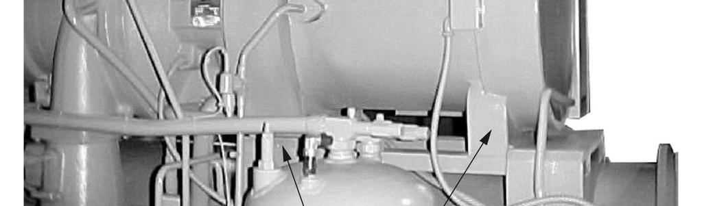
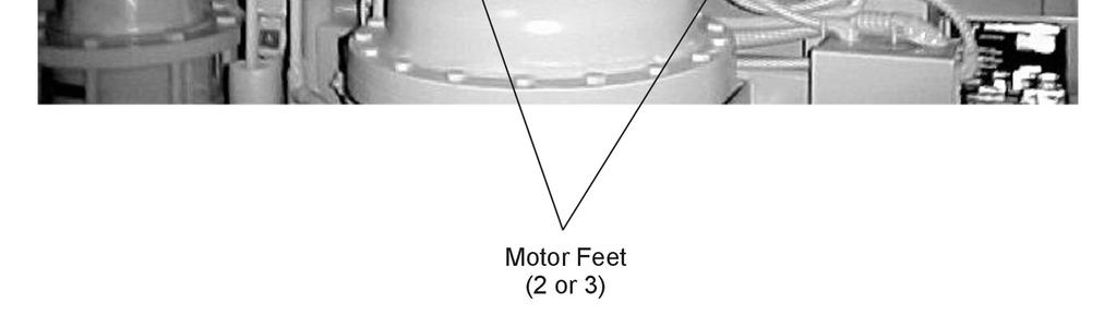
6 Maximum entering condenser water temperature, startup: design plus 5 degrees F (2.7 degrees C) Maximum entering condenser water temperature, operating: job specific design temperature Minimum entering condenser water temperature, operating: see page 6. Minimum leaving chilled water temperature: 38 F (3.3 C) Minimum leaving chilled fluid temperature with correct anti-freeze fluid: 15 F (9.4 C) Maximum entering chilled water temperature, operating: 90 F (32.2 C) Maximum oil cooler/vfd entering temperature: 90 F (32.2 C) Minimum oil cooler/vfd entering temperature: 42 F (5.6 C) Vibration Pads The shipped-loose neoprene vibration pads should be located under the corners of the unit (unless the job specifications state otherwise). They are installed to be flush with the sides and outside edge of the feet. Most WSC units have six mounting feet although only the outer four are required. Six pads are shipped and the installer can place pads under the middle feet if desired. Mounting Make sure that the floor or structural support is adequate to support the full operating weight of the complete unit. It is not necessary to bolt the unit to the mounting slab or framework; but should this be desirable, 1 1/8" (28.5 mm) mounting holes are provided in the unit support at the four corners. Note: Units are shipped with refrigerant and oil valves closed to isolate these fluids for shipment. Valves must remain closed until start-up by the McQuay technician. Nameplates There are several identification nameplates on the chiller: The unit nameplate is located on the side of the Unit Control Panel. It has a Style No. XXXX and Serial No. XXXX, both are unique to the unit and will identify it. These numbers should be used to identify the unit for service, parts, or warranty questions. This plate also has the unit refrigerant charge. Vessel nameplates are located on the evaporator and condenser. Along with other information, they have a National Board Number (NB) and a serial number, either of which identify the vessel (but not the entire unit). A compressor nameplate is located on the compressor itself and contains identification numbers. System Water Volume All chilled water systems need adequate time to recognize a load change, respond to that load change and stabilize, without undesirable short cycling of the compressors or loss of control. In air conditioning systems, the potential for short cycling usually exists when the building load falls below the minimum chiller plant capacity or on close-coupled systems with very small water volumes. Some of the things the designer should consider when looking at water volume are the minimum cooling load, the minimum chiller plant capacity during the low load period and the desired cycle time for the compressors. Assuming that there are no sudden load changes and that the chiller plant has reasonable turndown, a rule of thumb of gallons of water volume equal to two to three times the chilled water gpm flow rate is often used. A properly designed storage tank should be added if the system components do not provide sufficient water volume. 6 Centrifugal Chillers IMM WSCWDC-5
7 Low Condenser Water Temperature Operation When ambient wet bulb temperature are lower than design, the condenser water temperature can be allowed to fall. Lower temperatures will improve chiller performance. Up to 300 Tons McQuay centrifugal chillers up to 300 tons are equipped with electronic expansion valves (EXV) and will start and run with entering condenser water temperatures as low as shown in Figure 3 or as calculated from the following equation on which the curves are based. Figure 3, Minimum Entering Condenser Water Temperature (EXV) Minimum Entering Condenser Water Temperature - 10 F Range LChWT 42 LChWT 46 LChWT 55.0 ECWT, F Percent Load Min. ECWT = *(LWT) - DT FL* (PLD/100) + 22*(PLD/100) 2 ECWT = Entering condenser water temperature LWT = Leaving chilled water temperature DT FL = Chilled Water Delta-T at full load PLD = The percent chiller load point to be checked For example; at 44 F LWT, 10 degree F Delta-T, and 50% full load operation, the entering condenser water temperature could be as low as 44.5 F. This provides excellent operation with water-side economizer systems. Over 300 Tons Chillers over 300 tons are equipped with thermal expansion valves (TXV) and will start and run with entering condenser water temperatures as low as calculated by the following equation and shown in the chart following. Min. ECWT = LWT 1.25* DT FL (PLD/100) + 22*(PLD/100) 2 ECWT = Entering condenser water temperature LWT = Leaving chilled water temperature DT FL = Chilled Water Delta-T at full load PLD = The percent chiller load point to be checked IMM WSCWDC-5 Centrifugal Chillers 7
8 Figure 4, Minimum Entering Condenser Water Temperature (TXV) Minimum Entering Condenser Water Temperature - 10 F Range LChWT 42 LChWT 46 LChWT 55.0 ECWT, F Percent Load For example; at 44 F LWT, 10 degree F Delta-T, and 50% full load operation, the entering condenser water temperature could be as low as 50.5 F. This provides excellent operation with water-side economizer systems. Depending on local climatic conditions, using the lowest possible entering condenser water temperature may be more costly in total system power consumed than the expected savings in chiller power would suggest, due to the excessive fan power required. Cooling tower fans must continue to operate at 100% capacity at low wet bulb temperatures. As chillers are selected for lower kw per ton, the cooling tower fan motor power becomes a higher percentage of the total peak load chiller power. McQuay s Energy Analyzer program can optimize the chiller/tower operation for specific buildings in specific locales. Even with tower fan control, some form of water flow control, such as tower bypass, is recommended. Figure 5 illustrates two temperature actuated tower bypass arrangements. The Cold Weather scheme provides better startup under cold ambient air temperature conditions. The check valve may be required to prevent entraining air at the pump inlet. Figure 5, Bypass, Mild Weather Operation Bypass, Cold Weather Operation 8 Centrifugal Chillers IMM WSCWDC-5

9 Water Piping Water Pumps Avoid the use of 3600/3000-rpm (two-pole motor) pump motors. It is not uncommon to find that these pumps operate with objectionable noise and vibration. It is also possible to build up a frequency beat due to the slight difference in the operating rpm of the pump motor and the McQuay centrifugal motor. McQuay encourages the use of 1750/1460 rpm (four-pole) pump motors. Vessel Drains at Start-up Unit vessels are drained of water in the factory and are shipped with the drain plugs in the heads removed and stored in the control panel or with open ball valves in the drain hole. Be sure to replace plugs or close the valves prior to filling the vessel with fluid. Evaporator and Condenser Water Piping All evaporators and condensers come standard with Victaulic AWWA C-606 groove nozzles (also suitable for welding), or optional flange connections. The installing contractor must provide matching mechanical connections or transitions of the size and type required. A heat recovery chiller, HSC, (shown on the right) has two sets of condenser piping; one for the tower, one for the heating system. The tower connections are always the inboard pair of connections. In the figure to the right, the condenser connections are left-hand when viewed from the front of the unit (Unit Control Panel and Interface Panel side), so in this case, the righthand condenser connections would be for the tower. If the condenser connections were on the other end ( righthand ), the tower connections would be the left-hand pair of Important Note on Welding If welding is to be performed on the mechanical or flange connections, remove the solid-state temperature sensor and thermostat bulbs from the wells to prevent damage to those components. Also properly ground the unit or severe damage to the MicroTech II unit controller can occur. Water pressure gauge connection taps and gauges must be provided in the field piping at the inlet and outlet connections of both vessels for measuring the water pressure drops. The pressure drops and flow rates for the various evaporators and condensers are job specific and the original job documentation can be consulted for this information. Refer to the nameplate on the vessel shell for identification. Be sure that water inlet and outlet connections match certified drawings and stenciled nozzle markings. The condenser is connected with the coolest water entering at the bottom to maximize subcooling. Note: When common piping is used for both heating and cooling modes, care must be taken to provide that water flowing through the evaporator cannot exceed 110 F which can cause the relief valve to discharge refrigerant or damage controls. The piping must be supported to eliminate weight and strain on the fittings and connections. Piping must also be adequately insulated. A cleanable 20-mesh water strainer must be installed in both water inlet lines. Sufficient shutoff valves must be installed to permit draining the water from the evaporator or condenser without draining the complete system. IMM WSCWDC-5 Centrifugal Chillers 9
10 Flow Switch A water flow switch must be installed in the vessel outlet piping to signal the presence of adequate water flow to the vessels before the unit can start. They also serve to shut down the unit in the event that water flow is interrupted to guard against evaporator freeze-up or excessive discharge pressure. Thermal dispersion flow switches are available from McQuay as a factory-mounted option. It is mounted in an evaporator and condenser water nozzle and factory wired. A paddle type flow switch can be supplied by the owner for field mounting and wiring. Figure 6, Flow Switch Mounting Flow direction marked on switch I in. (25mm) NPT flow switch connection Tee If flow switches, by themselves, are being used, electrical connections in the Unit Control Panel must be made from the common T3-S terminal to terminal CF for the condenser switch and T3-S to terminal EF for the evaporator switch. See Figure 15, Field Wiring Diagram on page 27. The normally open contacts of the flow switch must be wired between the terminals. Flow switch contact quality must be suitable for 24 VAC, low current (16ma). Flow switch wire must be in separate conduit from any high voltage conductors (115 VAC and higher). Table 1, Flow Switch Flow Rates Pipe Size inch 1 1/4 1 1/ / (NOTE!) mm 32 (2) 38 (2) (3) (4) 127 (4) 153 (4) 204 (5) gpm Flow Min. Lpm Adjst. No gpm Flow Lpm gpm Flow Max. Lpm Adjst. No gpm Flow Lpm NOTES: 1. A segmented 3-inch paddle (1, 2, and 3 inches) is furnished mounted, plus a 6-inch paddle loose. 2. Flow rates for a 2-inch paddle trimmed to fit the pipe. 3. Flow rates for a 3-inch paddle trimmed to fit the pipe. 4. Flow rates for a 3-inch paddle. 5. Flow rates for a 6-inch paddle 6. There is no data for pipe sizes above 8-inch. A switch minimum setting should provide protection against no flow and close well before design flow is reached. Alternatively, for a higher margin of protection, normally open auxiliary contacts in the pump starters can be wired in series with the flow switches as shown in Figure 15, Field Wiring Diagram on page Centrifugal Chillers IMM WSCWDC-5
11 CAUTION Freeze Notice: Neither the evaporator nor the condenser is self-draining; both must be blown out to help avoid damage from freezing. The piping should also include thermometers at the inlet and outlet connections and air vents at the high points. The water heads can be interchanged (end for end) so that the water connections can be made at either end of the unit. If this is done, new head gaskets must be used and control sensors relocated. In cases where the water pump noise can be objectionable, vibration isolation sections are recommended at both the inlet and outlet of the pump. In most cases, it will not be necessary to provide vibration eliminator sections in the condenser inlet and outlet water lines. But they can be required where noise and vibration are critical. Cooling Towers The condenser water flow rate must be checked to be sure that it conforms to the system design. Some form of temperature control is also required if an uncontrolled tower can supply water below about 65 F (18 C). If tower fan control is not adequate, a tower bypass valve is recommended. Unless the system and chiller unit are specifically for condenser bypass or variable condenser flow is not recommended since low condenser flow rates can cause unstable operation and excessive tube fouling. The condenser water pumps must cycle on and off with the unit. See Figure 15, Field Wiring Diagram on page 27 for wiring details. Tower water treatment is essential for continued efficient and reliable unit operation. If not available in-house, competent water treatment specialists can be contracted. Heat Recovery Chillers HSC heat recovery chillers control the chilled water leaving temperature. The cooling load determines compressor loading and unloading, the same as in a conventional chiller. A heat recovery chiller s control algorithms are identical to a conventional cooling-only chiller. The temperature of the hot water being supplied from the recovery condenser to the heating load is established by manipulating the cooling tower water temperature. The 3-way cooling tower bypass valve is controlled by the heating water inlet temperature to the recovery bundle of the condenser. Based on the signal the 3-way valve gets from the heating hot water sensor, it will bypass sufficient water around the tower to force the tower condenser water loop high enough for the recovery bundle to produce the desired hot water temperature. The chilled water and its control system do not know that the condensing pressure and condenser water temperatures are being regulated in this manner. IMM WSCWDC-5 Centrifugal Chillers 11
12 Figure 7, Heat Recovery Schematic HEAT LOAD AUXILIARY HEATER OPEN CIRCUIT TOWER TC RECOVERY CONDENSER TOWER CONDENSER HEAT RECOVERY CHILLER LEGEND TC TEMPERATURE CONTROL POINT PUMP EVAPORATOR TC COOLING LOAD 12 Centrifugal Chillers IMM WSCWDC-5


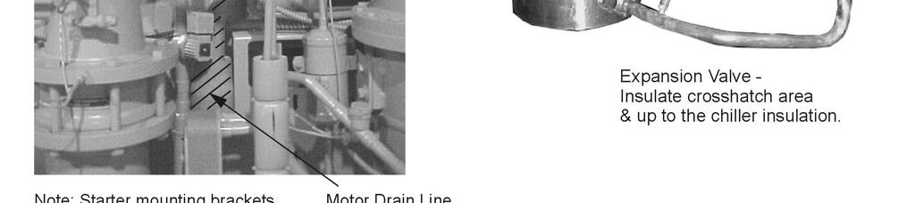
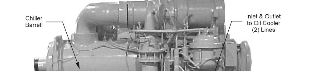
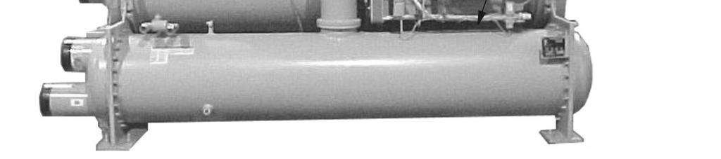
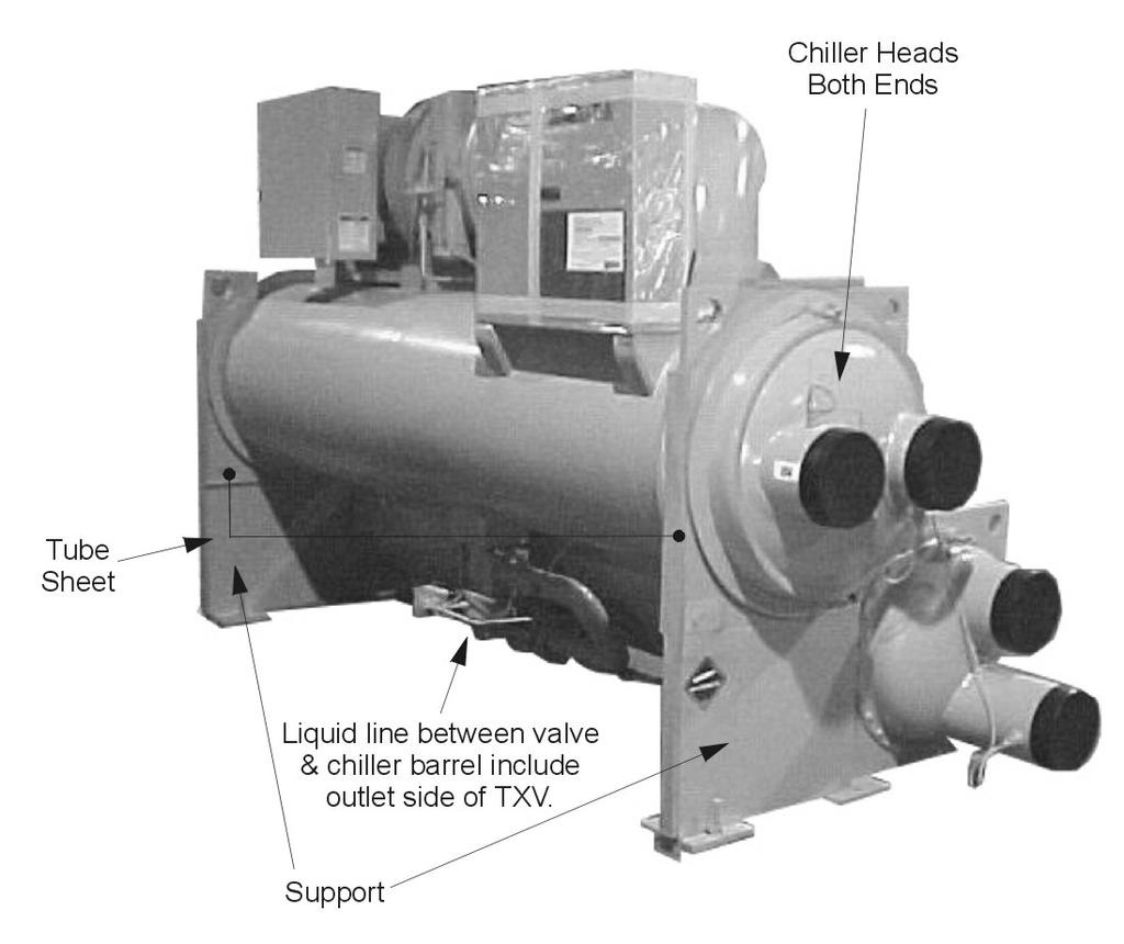
13 Field Insulation Guide Figure 8, Insulation Requirements, Cooling-only Units IMM WSCWDC-5 Centrifugal Chillers 13
14 14 Centrifugal Chillers IMM WSCWDC-5
15 Physical Data and Weights Evaporator The standard insulation of cold surfaces includes the evaporator and non-connection water head, suction piping, compressor inlet, motor housing, and motor coolant outlet line. Insulation is UL recognized (File # E55475). It is 3/4" thick ABS/PVC flexible foam with a skin. The K factor is 0.28 at 75 F. Sheet insulation is fitted and cemented in place forming a vapor barrier, then painted with a resilient epoxy finish that resists cracking. The insulation complies to, or has been tested in accordance, with the following: ASTM-C-177 ASTM-C-534 Type 2 UL 94-5V ASTM-D C1 ASTM E 84 MEA M Vol. N CAN/ULC S102-M88 Refrigerant-side design pressure is 200 psi (1380 kpa) on WSC/WCC/HSC units and 180 psi (1242 kpa) on WDC units. Water-side is 150 psi (1034 kpa) on all. In the event insulation is to be field-installed, none of the cold surfaces identified above will be factory insulated. Required field insulation is shown beginning on page 13. Approximate total square footage of insulation surface required for individual packaged chillers is tabulated by evaporator code and can be found below. Table 2, Evaporator Physical Data Evaporator Code WSC WDC WCC Refrigerant Charge lb. (kg) Evaporator Water Capacity, gal (L) Insulation Area Sq. Ft. (m 2 ) Vessel Weight lb. (kg) Number of Relief Valves E1809 X 434 (197) 37 (138) 75 (7.0) 2734 (1239) 1 E1812 X 347 (158) 27 (103) 78 (7.2) 2370 (1075) 1 E2009 X 561 (254) 34 (164) 82 (7.6) 3026 (1371) 1 E2012 X 420 (190) ) 84 (7.8) 2713 (1231) 1 E2209 X 729 (331) 54 (206) 66 (6.1) 3285 (1488) 1 E2212 X 500 (227) 45 (170) 90 (8.3) 2877 (1305) 1 E2212 X 645 (291) 63 (240) 90 (8.3) 3550 (1609) 1 E2216 X 1312 (595) 79 (301) 144 (13.4) 4200 (1903) 1 E2412 X 1005 (456) 88 (335) 131 (12.1) 4410 (1999) 1 E2416 X 1424 (646) 110 (415) 157 (14.6) 5170 (2343) 1 E2609 X 531 (249) 54 (295) 76 (7.1) 2730 (1238) 1 E2612 X 708 (321) 72 (273) 102 (9.4) 3640 (1651) 1 E2612 X 925 (418) 101 (381) 102 (9.4) 4745 (2150) 1 E2616 X 1542 (700) 126 (478) 162 (15.0) 5645 (2558) 1 E3009 X 676 (307) 67 (252) 86 (8.0) 3582 (1625) 1 E3012 X 901 (409) 89 (336) 115 (10.6) 4776 (2166) 1 E3016 X 2117 (960) 157 (594) 207 (19.2) 7085 (3211) 2 E3609 X 988 (720) 118 (445) ) 5314 (2408) 1 E3612 X 1317 (597) 152 (574) 129 (11.9) 6427 (2915) 1 E3616 X 3320 (1506) 243 (918) 239 (22.2) 9600 (4351) 2 E3620 X 4150 (1884) 434 (1643) 330 (30.6) (5675) 2 E4212 X 1757 (797) 222 (841) 148 (13.7) 8679 (3937) 1 E4216 X 4422 (2006) 347 (1313) 264 (24.5) (5536) 2 E4220 X 4713 (2138) 481 (1819) 330 (30.6) (6819) 2 E4220 X 4713 (2138) 481 (1819) 330 (30.6) (7194) 2 E4812 X 2278 (1033) 327 (1237) 169 (15.6) (4964) 2 E4816 X 4690 (2128) 556 (2106) 302 (28.1) (7429) 2 E4820 X 5886 (2670) 661 (2503) 377 (35.0) (7791) 2 E4820 X 5886 (2670) 661 (2503) 377 (35.0) (8349) 2 1. Refrigerant charge is approximate since the actual charge will depend on other variables. Actual charge will be shown on the unit nameplate. 2. Water capacity is based on standard tube configuration and standard dished heads. 3. The evaporator charge includes the maximum condenser charge available with that evaporator and is therefore the maximum charge for a total unit with the evaporator. Actual charge for a specific selection can vary with tube count and can be obtained from the McQuay Selection Program. The program will not allow a selection where the unit charge exceeds the condenser pumpdown capacity. IMM WSCWDC-5 Centrifugal Chillers 15
16 Condenser With positive pressure systems, the pressure variance with temperature is always predictable, and the vessel design and relief protection are based upon pure refrigerant characteristics. R-134a requires ASME vessel design, inspection and testing and uses spring-loaded pressure relief valves. When an over pressure condition occurs, spring-loaded relief valves purge only that refrigerant required to reduce system pressure to their set pressure, and then close. Refrigerant side design pressure is 200 psi (1380 kpa) on WSC/WCC/HSC units and 225 psi (1552 kpa) on WDC units. Water side design is 150 psi (1034 kpa) on all. Pumpdown To facilitate compressor service, all McQuay centrifugal chillers are designed to permit pumpdown and isolation of the entire refrigerant charge in the unit s condenser. Dual compressor units and single compressor units equipped with the optional suction shutoff valve can also be pumped down into the evaporator. Table 3, Condenser Physical Data Condenser Code WSC WDC WCC Pumpdown Capacity lb. (kg) Water Capacity gal. (L) Vessel Weight lb. (kg) Number of Relief Valves C1609 X 468 (213) 33 (125) 1645 (746) 2 C1612 X 677 (307) 33 (123) 1753 (795) 2 C1809 X 597 (271) 43 (162) 1887 (856) 2 C1812 X 845 (384) 44 (166) 2050 (930) 2 C2009 X 728 (330) 47 (147) 1896 (860) 2 C2012 X 971 (440) 62 (236) 2528 (1147) 2 C2209 X 822 (372) 73 (278) 2596 (1169) 2 C2212 X 1183 (537) 76 (290) 2838 (1287) 2 C2212 X 1110 (504) 89 (337) 3075 (1395) 2 C2216 X 1489 (676) 114 (430) 3861 (1751) 2 C2416 X 1760 (799) 143 (540) 4647 (2188) 2 C2609 X 1242 (563) 83 (314) 2737 (1245) 2 C2612 X 1656 (751) 111 (419) 3650 (1660) 2 C2616 X 2083 (945) 159 (603) 5346 (2425) 2 C3009 X 1611 (731) 108 (409) 3775 (2537) 2 C3012 X 2148 (975) 144 (545) 5033 (3383) 2 C3016 X 2789 (1265) 207 (782) 6752 (3063) 4 C3612 X 2963 (1344) 234 (884) 7095 (3219) 2 C3616 X 3703 (1725) 331 (1251) 9575 (4343) 4 C3620 X ) 414 (1567) (5797) 4 C4212 X 3796 (1722) 344 (1302) 9984 (4529) 2 C4216 X 5010 (2273) 475 (1797) (5743) 4 C4220 X 5499 (2494) 634 (2401) (7785) 4 C4220 X 5499 (2497) 634 (2400) (8156) 4 C4812 X 4912 (2228) 488 (1848) (5826) 4 C4816 X 5581 (2532) 717 (2715) (8530) 4 C4820 X 7034 (3191) 862 (3265) (10481) 4 C4820 x 7034 (3193) 862 (3263) (11045) 4 1. Condenser pumpdown capacity based on 90% full at 90 F. 2. Water capacity based on standard configuration and standard heads and can be less with lower tube counts. 3. See Relief Valves section for additional information. Compressor Table 4, Compressor Weights Compressor Size Weight lb. (kg) 870 (390) 3200 (1440) 3200 (1440) 3200 (1440) 6000 (2700) 6000 (2700) 6000 (2700) 16 Centrifugal Chillers IMM WSCWDC-5
17 Oil Coolers McQuay centrifugal chillers, sizes 063 through 126, have a factory-mounted, water-cooled oil cooler, temperature-controlled water regulating valve and solenoid valve per compressor. Model 050 chillers have refrigerant-cooled oil coolers and require no cooling water connection. WSC/HSC single compressor cooling water connections are located near the compressor and are shown on the specific unit certified drawings. Also see Figure 11 on page 19. Dual compressor chillers, WDC/ and WCC are equipped as above, but the water piping for the two oil coolers is factory-piped to a common inlet and outlet connection located in the tube sheet under the evaporator. The exception to this is the WDC 100 and 126 with 16-foot shells, where the common connections are centered at the rear of the unit. See Figure 12 on page 19. Field water piping to the inlet and outlet connections must be installed according to good piping practices and include stop valves to isolate the cooler for servicing. A cleanable filter (40 mesh maximum), and drain valve or plug must also be field-installed. The water supply for the oil cooler should be from the chilled water circuit or from a clean, independent source, no warmer than 80 F (27 C), such as city water. When using chilled water, it is important that the water pressure drop across the evaporator is greater than the pressure drop across the oil cooler or insufficient oil cooler flow will result. If the pressure drop across the evaporator is less than the oil cooler, the oil cooler must be piped across the chilled water pump, provided that its pressure drop is sufficient. The water flow through the oil cooler will be adjusted by the unit's regulating valve so that the temperature of oil supplied to the compressor bearings (leaving the oil cooler) is between 95 F and 105 F (35 C and 40 C). Table 5, WSC, Oil Cooler Data Cold Side Water WSC/HSC Flow, gpm Inlet Temperature, F Outlet Temperature, F Pressure Drop, ft WSC/HSC Flow, gpm Inlet Temperature, F Outlet Temperature, F Pressure Drop, ft Table 6, WSC with Mounted VFD, Oil Cooler Data Cold Side Water WSC/HSC Flow, gpm Inlet Temperature, F Outlet Temperature, F Pressure Drop, ft WSC/HSC Flow, gpm Inlet Temperature, F Outlet Temperature, F Pressure Drop, ft NOTES: 1. WDC dual compressor units will have twice the cooling water flow rate of the comparable WSC chiller and the pressure drop will be the same. 2. Pressure drops include valves on the unit. IMM WSCWDC-5 Centrifugal Chillers 17
18 Table 7, Freestanding VFD, Cooling Requirements Cooling Water Cooling Water Cooling Water Cooling Water WSC/HSC Flow, gpm Inlet Temperature, F Outlet Temperature, F Pressure Drop, ft WSC/HSC Flow, gpm Inlet Temperature, F Outlet Temperature, F Pressure Drop, ft Compressors using chilled water for oil cooling will often start with warm "chilled water" in the system until the chilled water loop temperature is pulled down. Data given above includes that condition. As can be seen, with cooling water in the 45 F to 65 F (7 C to 18 C) range, considerably less water will be used, and the pressure drop will be greatly reduced. When supplied with city water, the oil piping must discharge through a trap into an open drain to prevent draining the cooler by siphoning. The city water can also be used for cooling tower makeup by discharging it into the tower sump from a point above the highest possible water level. NOTE: Particular attention must be paid to chillers with variable chilled water flow through the evaporator. The pressure drop available at low flow rates can very well be insufficient to supply the oil cooler with enough water. In this case an auxiliary booster pump can be used or city water employed. Figure 9, Oil Cooler Piping Across Chilled Water Pump PUMP CHILLER R OIL COOLER S SOLENOID VALVE STOP VALUE STOP VALVE STRAINER MAX. 40 MESH DRAIN VALVE OR PLUG 18 Centrifugal Chillers IMM WSCWDC-5

 Figure 12, Oil Cooler Connections, WDC 100/126, 16 Foot Shells Solenoid Valves Note: All other WDC units have oil cooler")

19 Figure 10, Oil Cooler Piping With City Water R OIL COOLER S SOLENOID VALVE WATER SUPPLY COOLING TOWER STOP VALVE STRAINER MAX. 40 MESH DRAIN VALVE OR PLUG COOLING TOWER MAKEUP DISCHARGE ABOVE HIGHEST POSSIBLE WATER LEVEL OPEN DRAIN Figure 11, Oil Cooler Connections, WSC/HSC Units Oil Reservoir Compressor Controller & Lub Control Box Solenoid Valve Inlet Connection (Inside) Temperature Control Valve Outlet Connection (Outside) Figure 12, Oil Cooler Connections, WDC 100/126, 16 Foot Shells Solenoid Valves Note: All other WDC units have oil cooler connections located on the right hand tube sheet under the evaporator. Temperature Control Valves Inlet Connection Outlet Connection Table 8, Cooling Water Connection Sizes IMM WSCWDC-5 Model WSC/HSC , Conn Size (in.) ¾ in. Centrifugal Chillers WDC , WSC/HSC in. WDC/WCC ½ in. 19
20 Oil Heater The oil sump is equipped with an immersion heater that is installed in a tube so that it can be removed without disturbing the oil. Relief Valves As a safety precaution and to meet code requirements, each chiller is equipped with pressure relief valves located on the condenser, evaporator, and oil sump vessel for the purpose of relieving excessive refrigerant pressure (caused by equipment malfunction, fire, etc.) to the atmosphere. Most codes require that relief valves be vented to the outside of a building, and this is a desirable practice for all installations. Relief piping connections to the relief valves must have flexible connectors. Note: Remove plastic shipping plugs (if installed) from the inside of the valves prior to making pipe connections. Whenever vent piping is installed, the lines must be run in accordance with local code requirements; where local codes do not apply, the latest issue of ANSI/ASHRAE Standard 15 code recommendations must be followed. Condensers have two relief valves as a set with a three-way valve separating the two valves (large condensers will have two such sets). One valve remains active at all times and the second valve acts as a standby. See pages 15 and 16 for the number of valve on specific vessels. Table 9, Relief Valve Data Chiller Relief Valve Location Pressure Setting Discharge Cap. WSC/WPV Evaporator Top of Evaporator 200 psi 75.5 lb air/min Condenser Top of Condenser 200 psi 75.5 lb air/min WDC Evaporator Top of Evaporator 180 psi 68.5 lbair/min Condenser Top of Condenser 225 psi 84.4 lb air/min Oil Sump (All Except WDC 050) Oil Pump Top of Oil Sump Cover 200 psi 5.0 lb air/min WDC 050 Compressor End of Motor Cover 200 psi 5.0 lb air/min Figure 13, Condenser 3-Way Valve 20 Centrifugal Chillers IMM WSCWDC-5
21 Refrigerant Vent Piping Relief valve connection sizes are one-inch FPT and are in the quantity shown in Table 2 and Table 3 on page 15. Twin relief valves mounted on a transfer valve are used on the condenser so that one relief valve can be shut off and removed, leaving the other in operation. Only one of the two is in operation at any time. Where four valves are shown in the table, they consist of two valves, each mounted on two transfer valves. Only two relief valves of the four are active at any time. Vent piping is sized for only one valve of the set since only one can be in operation at a time. In no case would a combination of evaporator and condenser sizes require more refrigerant than the pumpdown capacity of the condenser. Condenser pumpdown capacities are based on the current ANSI/ASHRAE Standard 15 that recommend 90% full at 90 F (32 C). To convert values to the older ARI standard, multiply pumpdown capacity by Sizing Vent Piping (ASHRAE Method) Relief valve pipe sizing is based on the discharge capacity for the given evaporator or condenser and the length of piping to be run. Discharge capacity for R-134a vessels is calculated using a complicated equation that accounts for equivalent length of pipe, valve capacity, Moody friction factor, pipe ID, outlet pressure and back pressure. The formula, and tables derived from it, is contained in ASHRAE Standard McQuay centrifugal units have relief valve settings of 180 psi, 200 psi, and 225 psi, and resultant valve discharge capacities of 68.5 # air/min, 75.5 # air/min, and 84.4 # air/min respectively. Using the ASHRAE formula and basing calculations on the 225 psi design yields a conservative pipe size, which is summarized in Table 10. The table gives the pipe size required per relief valve. When valves are piped together, the common piping must follow the rules set out in the following paragraph on common piping. Table 10. Relief Valve Piping Sizes Equivalent length (ft) Pipe Size inch (NPT) 1 1/4 1 1/ /2 3 4 Moody Factor NOTE: A 1-inch pipe is too small for the flow from the valves. A pipe increaser must always be installed at the valve outlet. Common Piping According to ASHRAE Standard 15, the pipe size cannot be less than the relief valve outlet size. The discharge from more than one relief valve can be run into a common header, the area of which cannot be less than the sum of the areas of the connected pipes. For further details, refer to ASHRAE Standard 15. The common header can be calculated by the formula: DCommon = D + D Dn The above information is a guide only. Consult local codes and/or latest version of ASHRAE Standard 15 for sizing data. Electrical Wiring, fuse and wire size must be in accordance with the National Electric Code (NEC). Standard NEMA motor starters require modification to meet McQuay specifications. Refer to McQuay Specification R or McQuay Product Manual PM WSC/WDC. Important: Voltage unbalance not to exceed 2% with a resultant current unbalance of 6 to 10 times the voltage unbalance per NEMA MG-1, 1998 Standard. This is an important restriction that must be adhered to. IMM WSCWDC-5 Centrifugal Chillers 21
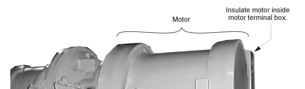
22 Power Wiring WARNING Qualified and licensed electricians must perform wiring. Shock hazard exists. Power wiring to compressors must be in proper phase sequence. Motor rotation is set up for clockwise rotation facing the lead end with phase sequence of Care must be taken that the proper phase sequence is carried through the starter to compressor. With the phase sequence of and L1 connected to T1 and T6, L2 connected to T2 and T4, and L3 connected to T3 and T5, rotation is proper. See diagram in terminal box cover. The McQuay start-up technician will determine the phase sequence. CAUTION Connections to terminals must be made with copper lugs and copper wire. Care must be taken when attaching leads to compressor terminals. Note: Do not make final connections to motor terminals until wiring has been checked and approved by a McQuay technician. Under no circumstances should a compressor be brought up to speed unless proper sequence and rotation have been established. Serious damage can result if the compressor starts in the wrong direction. Such damage is not covered by product warranty. It is the installing contractor's responsibility to insulate the compressor motor terminals when the unit voltage is 600 volts or greater. This is to be done after the McQuay start-up technician has checked for proper phase sequence and motor rotation. Following this verification by the McQuay technician, the contractor should obtain and apply the following items on medium voltage (above 600 volts) applications. Materials required: 1. Loctite brand safety solvent (12 oz. package available as McQuay part number 350A263H72) 2. 3M Co. Scotchfil brand electrical insulation putty (available in a 60-inch roll as McQuay part number 350A263H81) 3. 3M Co. Scotchkote brand electrical coating (available in a 15 oz. can with brush as McQuay Part Number 350A263H16) 4. Vinyl plastic electrical tape The above items are available at most electrical supply outlets. Application procedure: 1. Disconnect and lock out the power source to the compressor motor. 2. Using the safety solvent, clean the motor terminals, motor barrel adjacent to the terminals, lead lugs, and electrical cables within the terminal 4OX to remove all dirt, grime, moisture and oil. 3. Wrap the terminal with Scotchfil putty, filling in all irregularities. The final result should be smooth and cylindrical. 4. Doing one terminal at a time, brush the Scotchkote coating on the motor barrel to a distance of up to '/2" around the terminal and on the wrapped terminal, the rubber 22 Centrifugal Chillers IMM WSCWDC-5

23 insulation next to the terminal, and the lug and cable for approximately 10". Wrap additional Scotchfil insulation over the Scotchkote coating. 5. Tape the entire wrapped length with electrical tape to form a protective jacket. 6. Finally, brush on one more coat of Scotchkote coating to provide an extra moisture barrier. Remote Starter Display Wiring Remote mounted Wye-Delta, solid state, and acrossthe-line starters require field wiring to activate the optional ammeter display or the full metering display on the chiller s operator interface panel. The wiring is from the D3 board in the starter to the compressor controller and to the bias block; both located in the compressor control panel. Wiring Connection on Starter for Optional Display Figure 14, Field Wiring for Optional Display IMM WSCWDC-5 Centrifugal Chillers 23
24 Control Power Wiring The control circuit on the McQuay centrifugal packaged chiller is designed for 115-volts. Control power can be supplied from three different sources: 1. If the unit is supplied with a factory-mounted starter or VFD, the control circuit power supply is factory-wired from a transformer located in the starter or VFD. 2. A freestanding starter or VFD furnished by McQuay, or by the customer to McQuay specifications, will have a control transformer in it and requires field wiring to terminals in the compressor terminal box. 3. Power can be supplied from a separate circuit and fused at 20 amps inductive load. The control circuit disconnect switch must be tagged to prevent current interruption. Other than for service work, the switch is to remain on at all times in order to keep oil heaters operative and prevent refrigerant from diluting in oil. DANGER If a separate control power source is used, the following must be done to avoid severe personal injury or death from electrical shock: 1. Place a notice on the unit that multiple power sources are connected to the unit. 2. Place a notice on the main and control power disconnects that another source of power to the unit exists. In the event a transformer supplies control voltage, it must be rated at 3 KVA, with an inrush rating of 12 KVA minimum at 80% power factor and 95% secondary voltage. For control wire sizing, refer to NEC. Articles 215 and 310. In the absence of complete information to permit calculations, the voltage drop should be physically measured. Table 11, Control Power Line Sizing Maximum Length, ft (m) Wire Size (AWG) Maximum Length, ft (m) Wire Size (AWG) 0 (0) to 50 (15.2) (36.6) to 200 (61.0) 6 50 (15.2) to 75 (22.9) (61.0) to 275 (83.8) 4 75 (22.9) to 120 (36.6) (83.8) to 350 (106.7) 3 Notes: 1. Maximum length is the distance a conductor will traverse between the control power source and the unit control panel. 2. Panel terminal connectors will accommodate up to number 10 AWG wire. Larger conductors will require an intermediate junction box. The Unit On/Off switch located in the Unit Control Panel should be turned to the "Off" position any time compressor operation is not desired. Wiring for Optional BAS Interface The optional Building Automation System (BAS) interface utilizing the MicroTech II unit controller s Protocol Selectability feature is field wired and will be set-up by the McQuay startup service technician. The following manuals explain the wiring and mounting procedures: LONWORKS > IM 735 BACnet > IM 736 MODBUS > IM Centrifugal Chillers IMM WSCWDC-5
25 Flow Switches Water flow interlock terminals are provided on the Unit Control Panel terminal strip for fieldmounted switches. See the Field Wiring Diagram on page 27 or on the cover of the control panel for proper connections. The purpose of the water flow interlocks is to prevent compressor operation until such time as both the evaporator water and condenser water pumps are running and flow is established. If flow switches are not furnished factory-installed and wired, they must be furnished and installed by others in the field before the unit can be started. System Pumps Operation of the chilled water pump can be to 1) cycle the pump with the compressor, 2) operate continuously, or 3) start automatically by a remote source. The cooling tower pump must cycle with the machine. The holding coil of the cooling tower pump motor starter must be rated at 115 volts, 60 Hz, with a maximum volt-amperage rating of 100. A control relay is required if the voltage-amperage rating is exceeded. See the Field Wiring Diagram on page 27 or in the cover of control panel for proper connections. All interlock contacts must be rated for no less than 10 inductive amps. The alarm circuit provided in the control center utilizes 115-volts AC. The alarm used must not draw more than 10 volt amperes. See OM CentriMicro II for MicroTech II unit controller details. Control Panel Switches Three On/Off switches are located in the upper left corner of the main Unit Control Panel, which is adjacent to the operator interface panel, and have the following function: UNIT shuts down the chiller through the normal shutdown cycle of unloading the compressor(s) and provides a post-lube period. COMPRESSOR one switch for each compressor on a unit, executes an immediate shutdown without the normal shutdown cycle. CIRCUIT BREAKER disconnects optional external power to system pumps and tower fans. A fourth switch located on the left outside of the Unit Control Panel and labeled EMERGENCY STOP SWITCH stops the compressor immediately. It is wired in series with the COMPRESSOR On/Off switch. Surge Capacitors All units (except those with solid state starters or VFDs) are supplied with standard surge capacitors to protect compressor motors from electrical damage resulting from high voltage spikes. For unit-mounted starters, the capacitors are factory-mounted and wired in the starter enclosure. For free-standing starters, the capacitors are mounted in the motor terminal box and must be connected to the motor terminals with leads less than 18 inches (460 mm) long when the motor is being wired. IMM WSCWDC-5 Centrifugal Chillers 25
26 NOTES for Following Wiring Diagram 1. Compressor motor starters are either factory mounted and wired, or shipped separate for field mounting and wiring. If provided by others, starters must comply with McQuay specification 359AB99. All line and load side power conductors must be copper. 2. If starters are freestanding, then field wiring between the starter and the control panel is required. Minimum wire size for 115 Vac is 12 GA for a maximum length of 50 feet. If greater than 50 feet, refer to McQuay for recommended wire size minimum. Wire size for 24 Vac is 18 GA. All wiring to be installed as NEC Class 1 wiring system. All 24 Vac wiring must be run in separate conduit from 115 Vac wiring. Main power wiring between starter and motor terminal is factory-installed when units are supplied with unit-mounted starters. Wiring of free-standing starter must be wired in accordance with NEC and connection to compressor motor terminals must be made with copper wire and copper lugs only. Control wiring on free-standing starters is terminated on a terminal strip in the motor terminal box (not the unit control panel). Wiring from the unit control panel to the motor terminal is done in the factory. 3. For optional sensor wiring, see unit control diagram. It is recommended that DC wires be run separately from 115 Vac wiring. 4. Customer furnished 24 or 120 Vac power for alarm relay coil can be connected between UTB1 terminals 84 power and 51 neutral of the control panel. For normally open contacts, wire between 82 & 81. For normally closed contacts, wire between 83 & 81. The alarm is operator programmable. The maximum rating of the alarm relay coil is 25 VA. 5. Remote on/off control of unit can be accomplished by installing a set of dry contacts between terminals 70 and Evaporator and condenser paddle type flow switches or water pressure differential switches are required and must be wired as shown. If field supplied pressure differential switches are used then these must be installed across the vessel and not the pump. 7. Customer supplied 115 Vac, 20 amp power for optional evaporator and condenser water pump control power and tower fans is supplied to unit control terminals (UTBI) 85 power / 86 neutral, PE equipment ground. 8. Optional customer supplied 115 Vac, 25 VA maximum coil rated chilled water pump relay (EP 1 & 2) can be wired as shown. This option will cycle the chilled water pump in response to building load. 9. The condenser water pump must cycle with the unit. A customer supplied 115 Vac 25 VA maximum coil rated condenser water pump relay (CP1 & 2) is to be wired as shown. 10. Optional customer supplied 115 Vac, 25 VA maximum coil rated cooling tower fan relays (CL - C4) can be wired as shown. This option will cycle the cooling tower fans in order to maintain unit head pressure. 11. Auxiliary 24 Vac rated contacts in both the chilled water and condenser water pump starters must be wired as shown. 12. For VFD, Wye-Delta, and solid state starters connected to six (6) terminal motors. The conductors between the starter and motor carry phase current and selection shall be based on 58 percent of the motor rated load amperes (RLA). Wiring of free-standing starter must be in accordance with the NEC and connection to the compressor motor terminals shall be made with copper wire and copper lugs only. Main power wiring between the starter and motor terminals is factory-installed when chillers are supplied with unit-mounted starters. 13. Optional Protocol Selectability BAS interfaces. The locations and interconnection requirements for the various standard protocols are found in their respective installation manuals, obtainable from the local McQuay sales office and also shipped with each unit: Modbus IM LonWorks IM BACnet IM The Full Metering or Amps Only Metering option will require some field wiring when free-standing starters are used. Wiring will depend on chiller and starter type. Consult the local McQuay sales office for information on specific selections. 26 Centrifugal Chillers IMM WSCWDC-5
27 Figure 15, Field Wiring Diagram MICROTECH CONTROL BOX TERMINALS (115V) (24V) GND PE 54 * COOLING TOWER FOURTH STAGE STARTER POWER * NOTE 7 NEUTRAL * NOTE 10 H O C4 A EP2 H O A C * COOLING TOWER THIRD STAGE STARTER * NOTE 10 H O C3 A EP1 O H A C 77 * COOLING TOWER SECONDH STAGE STARTER * NOTE 10 H O C2 A H O * COOLING TOWER FIRST STAGE STARTER * NOTE 10 H O C1 A T3-S EF CF CP2 A C COMMON 81 82(NO) 83(NC) A ALARM RELAY (NOTE 4) POWER 84 COOLING TOWER BYPASS VALVE COOLING TOWER VFD 1-10 VDC 1-10 VDC CP1 H O A C L1 L2 L3 COMPRESSOR MOTOR STARTER (NOTE 1) CP1 CP2 23(5A) 24(5) GND MICROTECH COMPRESSOR CONTROL BOX TERMINALS CTB1 NOTE VAC PE L1 L STARTER LOAD SIDE TERMINBALS VFD U V W T1 T6 T2 T4 T3 T5 COMPRESSOR TERMINALS STARTER LOAD SIDE TERMINBALS WYE-DELTA T1 T2 T3 T4 T5 T6 T1 T2 T3 T4 T5 T6 COMPRESSOR TERMINALS STARTER LOAD SIDE TERMINBALS SOLID STATE T1 T2 T3 NOTE 12 - FOR DC VOLTAGE AND 4-20 MA CONNECTIONS (SEE NOTE 3) - FOR DETAILS OF CONTROL REFER TO UNIT CONTROL SCHEMATIC COMPRESSOR CONTROL SCHEMATIC LEGEND: * FIELD SUPPLIED ITEM T1 T6 T2 T4 T3 T5 COMPRESSOR TERMINALS STARTER LOAD SIDE TERMINBALS MEDIUM AND HIGH VOLTAGE -LOAD- NOTE 2 LESS THAN 30V OR 24VAC T1 T2 T3 T1 T2 T3 COMPRESSOR TERMINALS A IMM WSCWDC-5 Centrifugal Chillers 27
28 Multiple Chiller Setup Single compressor chillers WSC and dual compressor chillers WDC and WCC have their main control components factory wired to an internal plan network so that the components can communicate with each other, within the chiller itself. On multi-chiller applications, up to four chillers, either single, or dual compressor, can be interconnected by this internal plan. All that is required is simple field RS485 interconnecting wiring, the addition of accessory communication isolation board(s) 485OPDR (McQuay P/N ), and some MicroTech II control settings (see special WCC instructions at the end of this section). The 485OPDR isolation board can be purchased with the unit or separately, during or after chiller installation. The number of chillers minus one boards are required. plan Setup Interconnecting MicroTech II plan RS485 wiring should be installed by the installing contractor prior to start-up. The McQuay start-up technician will check the connections and make the necessary set point settings. 1. With no plan connections between chillers, disconnect chiller control power and set the DIP switches as shown in Table With all manual switches off, turn on control power to each chiller and set each OITS address (see Note 2 on page 29). 3. Verify correct nodes on each OITS Service Screen. 4. Connect chillers together (plan, RS485 wiring) as shown in Figure 16. The first chiller in the connection can be designated as Chiller A. The isolation board is attached to the DIN rail adjacent to the Chiller A unit controller. The isolation board has a pigtail that is plugged into J10 on the controller. Most chillers will already have a universal communication module (UCM) that connects the controller to the touchscreen already plugged onto J10. If this is the case, plug the isolation module pigtail into the empty RJ11 plan port on the UCM. This is equivalent to plugging into the unit controller directly. Next, interconnecting wiring is needed between Chiller A and Chiller B. Two Chillers: If only two chillers are to be connected, Belden M9841 (RS 485 Spec Cable) is wired from the 485OPDR isolation board (terminals A, B, and C) on Chiller A to the J11 port on the unit controller of Chiller B. At J11, the shield connects to GND, the blue/white wire to the (+) connection, and the white/blue to the (-) connection. Note that Chiller B does not have an isolation board. The last chiller (B in this case) to be connected does not need an isolation board. Three or More Chillers: If three or more chillers are to be connected, the interconnecting wiring is still made to Chiller B s J11 port. The second chiller (Chiller B) must have a 485OPDR isolator board that will be plugged into Chiller B s UCM plan port. Chiller B will look like Chiller A. The wiring from Chiller B to Chiller C will be the same as A to B. That is, Belden cable connects from A, B, and C on B s 485OPDR board to chiller C s L11 port. Chiller C has no 485OPDR isolation board. The procedure is repeated to the fourth chiller if four chillers are interconnected. 5. Verify correct nodes on each OITS Service Screen. 28 Centrifugal Chillers IMM WSCWDC-5
29 Figure 16, Communication Wiring PIGTAIL Chiller A 485 OPDR C B A P P UCM J10 J11 UNIT CONTROL BLU/WHT WHT/BLU SHIELD Chiller B 485 OPDR C B A P P UCM J10 PORT (+) (-) J11 PORT UNIT CONTROL BLU/WHT WHT/BLU SHIELD (+) (-) J11 Port UNIT CONTROL Chiller C NOTE: A fourth chiller, Chiller D would be connected to chiller C same as chiller C to chiller B. Table 12, Address DIP Switch Settings for Controllers Using plan. Chiller (1) A B C D Comp 1 Comp 2 Unit Operator Reserved Controller Controller Controller Interface (2) Reserved NOTES: 1. Up to four single or dual compressors can be interconnected. 2. The Operator Interface Touch Screen (OITS) setting is not a DIP switch setting. The OITS address is selected by selecting the service set screen. Then, with the Technician level password active, select the plan Comm button. Buttons A(7), B(15), C(23), D(31) will appear in the middle of the screen, then select the letter for the OITS address for the chiller that it is on. Then close the screen. Note that A is the default setting from the factory. 3. Six Binary Switches: Up is On, indicated by 1. Down is Off, indicated by 0. IMM WSCWDC-5 Centrifugal Chillers 29
30 MicroTech II Operator Interface Touch Screen (OITS) Settings Settings for any type of linked multiple compressor operation must be made to the MicroTech II controller. Settings on a dual compressor unit are made in the factory prior to shipment, but must be verified in the field before startup. Settings for multiple chiller installations are set in the field on the Operator Interface Touch Screen as follows: Maximum Compressors ON SETPOINTS - MODES screen, Selection #10 = 2 for a dual, 4 for 2 duals, 3 for three separate, single compressor chillers, etc. If all compressors in the system are to be available as normal running compressors, then the value entered in #10 should equal the total number of compressors. If any compressors are for standby and not operated in normal rotation, they should not be included in the compressor count in Selection #10. The Max Comp ON setting can be made in only one touchscreen, the system will observe the highest number set on all chillers-it is a global setting. Sequence and Staging SETPOINTS - MODES screen, Selection #12 & #14; #11 & #13. Sequence sets the sequence in which compressors will start. Setting one or more compressors to 1 evokes the automatic lead/lag feature and is the normal setting. The compressor with least starts will start first and the compressor with maximum hours will stop first, and so on. Units with higher numbers will stage on in sequence. The Modes setpoints will do several different types of operation (Normal, Efficiency, Standby, etc.) as described in the operating manual. The same Modes setting must be replicated on each chiller in the system. Nominal Capacity SETPOINTS - MOTOR screen, Selection #14. The setting is the compressor design tons. Compressors on dual units are always of equal capacity. WCC Settings Since the WCC is essentially two chillers combined into one counterflow, single pass, dualcircuit chiller, the compressor on the downstream circuit (leaving chilled water) must always be designated as the Stage 1 compressor-first on, last off. Operating Sequence For multiple-chiller, parallel operation, the MicroTech II controllers are tied together by a plan network and stage and control compressor loading among the chillers. Each compressor, single or dual compressor chiller, will stage on or off depending on the sequence number programmed into it. For example, if all are set to 1, the automatic lead/lag will be in effect. When chiller #1 is fully loaded, the leaving chilled water temperature will rise slightly. When the Delta-T above setpoint reaches the Staging Delta-T, the next chiller scheduled to start will receive a start signal and start its pumps if they are set up to be controlled by the Microtech controller. This procedure is repeated until all chillers are running. The compressors will load-balance themselves. If any of the chillers in the group are dual compressor, they will stage and load according to the staging instructions. See OM CentrifMicro II-3 for a complete description of the various staging sequences available. 30 Centrifugal Chillers IMM WSCWDC-5
31 Prestart System Checklist Chilled Water Yes No N/A Piping complete... Water system filled, vented... Pumps installed, (rotation checked), strainers cleaned... Controls (3-way, face and bypass dampers, bypass valves, etc.) operable... Water system operated and flow balanced to meet unit design requirements... Condenser Water (*) Cooling tower flushed, filled and vented... Pumps installed, (rotation checked), strainers cleaned... Controls (3-way, bypass valves, etc.) operable... Water system operated and flow balanced to meet unit requirements... Electrical 115-volt service completed, but not connected to control panel... Power leads connected to starter; load leads run to compressor ready for connection when service engineer is on hand for start-up... (Do not connect starter or compressor terminals) All interlock wiring complete between control panel and complies with specifications.. Starter complies with specifications... Pump starters and interlock wired... Cooling tower fans and controls wired... Wiring complies with National Electrical Code and local codes... Condenser pump starting relay (CWR) installed and wired... Miscellaneous Oil cooler water piping complete (units with water cooled oil coolers only)... Relief valve piping complete... Thermometer wells, thermometers, gauges, control wells, controls, etc., installed... Minimum system load of 80% of machine capacity available for testing and adjusting controls... (*) Includes heating hot water on heat recovery units. Note: This checklist must be completed and sent to the local McQuay service location two weeks prior to start-up. IMM WSCWDC-5 Centrifugal Chillers 31
 and the control diagram furnished with the unit before starting, operating, or")
32 Operation Operator Responsibilities It is important that the operator become familiar with the equipment and the system before attempting to operate the chiller. In addition to reading this manual, the operator should study operation manual OM CentrifMicro II (latest edition) and the control diagram furnished with the unit before starting, operating, or shutting it down. During the initial startup of the chiller the McQuay technician will be available to answer any questions and instruct in the proper operating procedures. It is recommended that the operator maintain an operating log for each individual chiller unit. In addition, a separate maintenance log should be kept of the periodic maintenance and servicing activities. This McQuay centrifugal chiller represents a substantial investment and deserves the attention and care normally given to keep this equipment in good working order. If the operator encounters abnormal or unusual operating conditions, it is recommended that a McQuay service technician be consulted. McQuay International conducts training for centrifugal operators at its factory Training Center in Staunton, Virginia, several times a year. These sessions are structured to provide basic classroom instruction and include hands-on operating and troubleshooting exercises. For further information, contact your McQuay representative. Standby Power It is essential that any centrifugal chiller connected to standby power come to a complete stop on grid power and then be restarted with the standby power. Attempting to switch from regular grid line power to auxiliary power while the compressor is running can result in extreme transient torque that will severely damage the compressor. MicroTech II Control Figure 17, MicroTech II Control Panel All chillers are equipped with the McQuay MicroTech II control system consisting of: Operator touchscreen interface panel (shown at the left). It consists of a 12- inch Super VGA color screen and a floppy drive. See Figure 17. Unit Control Panel containing the MicroTech II unit controller and miscellaneous switches and field connection terminals. Compressor Control Panel for each compressor containing the MicroTech II compressor controller and lube system control components. NOTE: Detailed information on the operation of the MicroTech II control is contained in the OM CentrifMicro II operating manual. 32 Centrifugal Chillers IMM WSCWDC-5
 AC-DC Signal Converter 115-volt Circuit")

33 Figure 18, Unit Control Panel ON/OFF Switches 110-volt Circuit Breaker plan Termination & Control Power Isolation Board UTB1 Unit Terminal Block Unit Controller Emergency OFF Switch Figure 19, Compressor Control Panel Terminal Board CTB1 Bias Block for Starter Display Option Connection 115V-24V Transformers (3) AC-DC Signal Converter 115-volt Circuit Breaker Latch Relay Heater Relay Compressor Relay Oil Pump Contactor Oil Pump Overload Relay Reset Button Oil Pump Starting Capacitor Guardistor Board Terminal Board, CTB2 plan Connection Compressor Microprocessor Transducer/Converter Board 5VDC Output, 0-5V Input RS485 Serial Card for Starter Display Option Connection IMM WSCWDC-5 Centrifugal Chillers 33

34 Capacity Control System The opening or closing of the inlet vanes controls the quantity of refrigerant entering the impeller thereby controlling the compressor capacity. The vane movement occurs in response to oil flow from the SA or SB 4-way solenoid valves, which in turn, respond to instructions from the unit microprocessor as it senses leaving chilled water temperature. This oil flow activates a sliding piston that rotates the vanes. Vane Operation The hydraulic system for the inlet guide vane capacity control operation consists of a 4-way normally open solenoid valve located in the oil management control panel or on the compressor close to the suction connection. Oil under pressure from the oil filter is directed by the 4-way valve to either or both sides of the piston, depending on whether the control signal is to load, unload, or hold. To open the vanes (loading compressor), solenoid SA is de-energized and SB is energized, allowing oil flow from port SA to one side of the piston. The other side drains through port SB. To close the vanes (unload compressor), valve SB is de-energized and valve SA is energized to move the piston and vanes toward the unload position. When both solenoid valves SA and SB are de-energized, full oil pressure is directed to both sides of the piston through ports SA and SB, and the vanes are held in that position. Refer to Figure 22 and Figure 23 for solenoid action. Note that both solenoids cannot be energized simultaneously. Vane Speed Metering Valves The speed at which the capacity control vanes are opened or closed can be adjusted to suit system operating requirements. Adjustable needle valves in the oil drain lines are used to control the rate of bleed-off and consequently the vane speed. These needle valves are part of the 4-way solenoid valve assembly located in the compressor lube box (Figure 21). The valves are normally factory set so that the vanes will move from fully closed to fully opened in the time periods shown in Table 13 on page 35. The speed must be slow enough to prevent over-controlling and hunting. The left adjusting screw is the SB needle valve for adjusting the vane OPENING speed for loading the compressor. Turn this screw clockwise to decrease the vane opening speed and counterclockwise to increase the opening speed. The right adjusting screw is the SA needle valve for adjusting the CLOSING speed to unload the compressor. The same adjustment method applies; clockwise to decrease closing, counterclockwise to increase vane closing. These adjustments are sensitive. Turn the adjusting screws a few degrees at a time. The vane speed is factory set and varies by compressor size. Figure 20, Needle Valve Location Open (Load) The start-up technician may readjust the vane speed at initial start-up to meet job conditions. Close (Unload) 34 Centrifugal Chillers IMM WSCWDC-5

35 Table 13, Vane Speed Factory Setting Compressor Model Opening Time Closing Time CE /2 min. 3/4-1 min. CE063 - CE min. 1-2 min CE min. 1-2 min. Figure 21, Oil Sump and Compressor Controller Panel Back Seat Port Relief Valve Oil Pump Contactor Oil Sump Oil Pump Capacitor Solenoid Valve Temperature Control Valve Compressor MicroTech II controller Cooling Water Inlet Cooling Water Outlet NOTE: 4-way solenoid valve and vane close switches are located on the compressor suction inlet. The mechanical high-pressure cutout is located in the discharge line. IMM WSCWDC-5 Centrifugal Chillers 35
Centrifugal Compressor Water Chillers
 Installation and Maintenance Manual IM 1044-4 Centrifugal Compressor Water Chillers Group: Chillers Part Number: IM1044 Effective: October 2017 Supersedes: : January 2015 Models WSC, WDC, WCC, HSC, TSC
Single/Dual Compressor Centrifugal Chillers
 Installation, Operation and Maintenance Manual D-EIMWC00812-14EN Original Instructions Single/Dual Compressor Centrifugal Chillers DWSC/DWDC 050, 063, 079, 087, 100, 113, 126, Cooling Only DWCC 100, 113,
The McQuay DISTINCTION SERIES. Single/Dual Compressor Centrifugal Chillers. Installation, Operating and Maintenance Manual
 Installation, Operating and Maintenance Manual IOMM WSCWDC-2 Group: Chiller Part Number: 736015420 Effective: April 2001 Supersedes: IOMM WSCWDC-1 The McQuay DISTINCTION SERIES Single/Dual Compressor Centrifugal
Water-Cooled Dual Compressor Screw Chiller
 Installation Manual IM 692-1 Group: Chiller Part Number: 629955 Effective: May 1997 Supersedes: IM663-1 IM683 IM692 Water-Cooled Dual Compressor Screw Chiller Installation Manual PFS 155C through PFS 210C,
Magnitude Frictionless Centrifugal Chiller
 Installation Manual IM 1033-1 Group: Chiller Part Number: 331499601 Effective: February 2010 Supersedes: November 2009 Magnitude Frictionless Centrifugal Chiller Model WME 400 to 550 tons (1400 to 1900
Magnitude Magnetic Bearing Centrifugal Chiller
 Installation Manual IM 10-2 Group: Chiller Part Number: 1499601 Effective: October 2011 Supersedes: August 2011 Magnitude Magnetic Bearing Centrifugal Chiller Model WME 0500, WME 0700 400 to 700 tons (1400
Magnitude Frictionless Centrifugal Chillers
 Installation Manual IM 1029 Group: Chiller Part Number: 331374601 Effective: February 2010 Supersedes: September 2009 Magnitude Frictionless Centrifugal Chillers Model WMC-145S to 400D (50/60 Hertz) R-134a
IOM Installation, Operation, and Maintenance Manual. Magnitude Magnetic Bearing Centrifugal Chillers
 Installation, Operation, and Maintenance Manual Magnitude Magnetic Bearing Centrifugal Chillers IOM 1210-1 Group: Chiller Part Number: IOM1210-1 Date: August 2014 Model WMC, C Vintage 125 to 400 Tons (440
C. ASME Compliance: Fabricate and label water chiller heat exchangers to comply with ASME Boiler and Pressure Vessel Code: Section VIII, Division 1.
 SECTION 236426 - ROTARY-SCREW WATER CHILLERS PART 1 - GENERAL 1.1 SUMMARY A. This Section includes packaged, water cooled or air cooled as scheduled, electric-motor-driven, rotary-screw water chillers
Call us today! (800)
") 500 TON AIR-COOLED CHILLER PA-ACCTR-500 Call us today! (800)341-4297 The 500-Ton portable chiller package features a Trane RTAC chiller unit. Trane leads the industry in providing some of the most reliable,
500 TON AIR-COOLED CHILLER PA-ACCTR-500 Call us today! (800)341-4297 The 500-Ton portable chiller package features a Trane RTAC chiller unit. Trane leads the industry in providing some of the most reliable,
.2 Section Waste Management and Disposal.
 Issued 2005/06/01 Section 15624 Packaged Rotary Screw Water Chillers Page 1 of 5 PART 1 General 1.1 RELATED SECTIONS.1 Section 01330 Submittal Procedures..2 Section 01355 Waste Management and Disposal..3
A. Air-conditioning and Refrigeration Institute (ARI) - Standard 550/590, latest edition, and ARI certification program.
 - Standard 550/590, latest edition, and ARI certification program.") 15684 ROTARY SCREW WATER CHILLERS ************************************************************************************************************* SPECIFIER: CSI MasterFormat 2004 number: 236423 An optional
15684 ROTARY SCREW WATER CHILLERS ************************************************************************************************************* SPECIFIER: CSI MasterFormat 2004 number: 236423 An optional
B. Unit construction shall comply with ASHRAE 15 Safety Code, NEC, and ASME applicable codes (U.S.A. codes).
.") Guide Specifications PART 1 GENERAL 1.01 SYSTEM DESCRIPTION Microprocessor controlled, air-cooled liquid chiller utilizing scroll compressors, low sound fans, hydronic pump system and optional fluid storage
Guide Specifications PART 1 GENERAL 1.01 SYSTEM DESCRIPTION Microprocessor controlled, air-cooled liquid chiller utilizing scroll compressors, low sound fans, hydronic pump system and optional fluid storage
SECTION ROTARY-SCREW WATER CHILLERS
 PART 1 GENERAL 1.01 SECTION INCLUDES A. Factory-assembled packaged chiller. B. Charge of refrigerant and oil. C. Controls and control connections. D. Chilled water connections. E. Electrical power connections.
Date: August 21, Proposal Number: G Engineer: Payment Terms: Net 30 Days
 Proposal Trane A Division of American Standard Inc. Prepared For: John Weston Desmet Ballestra Job Name: LAUER1 Biodiesel Chiller Pennsylvania Date: August 21, 2006 Proposal Number: G1-95502-1 Engineer:
IOM Installation, Operation, and Maintenance Manual. Magnitude Magnetic Bearing Centrifugal Chillers
 Installation, Operation, and Maintenance Manual Magnitude Magnetic Bearing Centrifugal Chillers IOM 1210-3 Group: Chiller Part Number: IOM1210-3 Date: June 2016 Model WMC, C Vintage 125 to 400 Tons (440
Water-Cooled Scroll Compressor Chillers
 Installation, and Maintenance Manual IMM WGZ-2 Group: Chiller Part Number: 331374401 Effective: October 2005 Supercedes: IOMM WGZ-1 Water-Cooled Scroll Compressor Chillers WGZ 030AW To WGZ 120AW, Packaged
A. Air-conditioning and Refrigeration Institute (ARI) - Standard 550/590, latest edition, and ARI certification program.
 - Standard 550/590, latest edition, and ARI certification program.") 15682 CENTRIFUGAL WATER CHILLERS ************************************************************************************************************* SPECIFIER: CSI MasterFormat 2004 number: 236416 An optional
15682 CENTRIFUGAL WATER CHILLERS ************************************************************************************************************* SPECIFIER: CSI MasterFormat 2004 number: 236416 An optional
Call us today! (800)
") PA-ACCTR-200 Call us today! (800)341-4297 The 200-Ton portable chiller package features a Trane RTAC chiller unit. Trane leads the industry in providing some of the most reliable, efficient and quiet chiller
PA-ACCTR-200 Call us today! (800)341-4297 The 200-Ton portable chiller package features a Trane RTAC chiller unit. Trane leads the industry in providing some of the most reliable, efficient and quiet chiller
Installation Manual IM
 Installation Manual IM 1128-1 Group: Chiller Part Number: 331375601 REV: 01 Effective: April 2012 Supersedes: February 2012 WSC, WME and WMC-B Centrifugal Chillers Reassembly of Knockdown Shipments COMPRESSOR
SECTION CENTRIFUGAL WATER CHILLERS Vibration Isolation Pumping Equipment (HVAC) Induced Draft Cooling Tower
 Induced Draft Cooling Tower") SECTION 15682 CENTRIFUGAL WATER CHILLERS PART 1 GENERAL 1.01 SUMMARY A. Related Sections: 1. 15240 - Vibration Isolation. 2. 15540 - Pumping Equipment (HVAC) 3. 15711 - Induced Draft Cooling Tower B. Removal
SECTION 15682 CENTRIFUGAL WATER CHILLERS PART 1 GENERAL 1.01 SUMMARY A. Related Sections: 1. 15240 - Vibration Isolation. 2. 15540 - Pumping Equipment (HVAC) 3. 15711 - Induced Draft Cooling Tower B. Removal
IOM Installation, Operation, and Maintenance Manual. Magnitude Magnetic Bearing Centrifugal Chillers
 Installation, Operation, and Maintenance Magnitude Magnetic Bearing Centrifugal Chillers IOM 1033-5 Group: Chiller Part Number: IOM1033 Date: October 2016 Supercedes: November 2012 Model WME 400 to 700
Water-Cooled Scroll Compressor Chillers
 Installation, Operation and Maintenance Manual IOMM WGZ-1 Group: Chiller Part Number: 330389301 Effective: October 2004 Supercedes: IOMM WGZ Water-Cooled Scroll Compressor Chillers WGZ 030AW To WGZ 100AW,
Call us today! (800)
") 150 TON AIR-COOLED CHILLER PA-ACCTR-150 Call us today! (800)341-4297 The 150-Ton portable chiller package features a Trane RTAC chiller unit. Trane leads the industry in providing some of the most reliable,
150 TON AIR-COOLED CHILLER PA-ACCTR-150 Call us today! (800)341-4297 The 150-Ton portable chiller package features a Trane RTAC chiller unit. Trane leads the industry in providing some of the most reliable,
Exclusively published and distributed by Architectural Computer Services, Inc. (ARCOM) for the AIA
 for the AIA") Page 236423-1 Copyright 2009 by The American Institute of Architects (AIA) Exclusively published and distributed by Architectural Computer Services, Inc. (ARCOM) for the AIA Modified by MSU Physical Plant
Page 236423-1 Copyright 2009 by The American Institute of Architects (AIA) Exclusively published and distributed by Architectural Computer Services, Inc. (ARCOM) for the AIA Modified by MSU Physical Plant
SECTION ROTARY SCREW WATER CHILLERS Vibration Isolation Pumping Equipment (HVAC) Induced Draft Cooling Tower
 Induced Draft Cooling Tower") SECTION 15684 ROTARY SCREW WATER CHILLERS PART 1 GENERAL 1.01 SUMMARY A. Related Sections: 1. 15240 - Vibration Isolation. 2. 15540 - Pumping Equipment (HVAC) 3. 15711 - Induced Draft Cooling Tower B.
SECTION 15684 ROTARY SCREW WATER CHILLERS PART 1 GENERAL 1.01 SUMMARY A. Related Sections: 1. 15240 - Vibration Isolation. 2. 15540 - Pumping Equipment (HVAC) 3. 15711 - Induced Draft Cooling Tower B.
GeneSys Air-Cooled Screw Compressor Chiller
 Installation and Maintenance Manual IMM AGSB- Group: Chiller Part Number: 330412001 Date: October 2005 Supersedes: IMM AGS-1 GeneSys Air-Cooled Screw Compressor Chiller AGS 230B through AGS 475B Hertz
PACKAGED AIR COOLED Product Data Catalog
 PACKAGED AIR COOLED Product Data Catalog MODELS ASP-10A ASP-15A ASP-20A ASP-00P ASP-00F ASP-00G A MEMBER OF MARDUK HOLDING COMPANY, LLC The Leader in Modular Chillers ETL and CSA Approved CHILLER MODULES
INSTALLATION INSTRUCTIONS
 INSTALLATION INSTRUCTIONS T CLASS TSA Series 6 to 20 Ton AIR CONDITIONERS 6 20 TONS 506147 01 06/11 Supersedes 3/11 Litho U.S.A. RETAIN THESE INSTRUCTIONS FOR FUTURE REFERENCE IMPORTANT The Clean Air Act
SECTION ROTARY SCREW WATER CHILLERS. B. Removal of Existing Refrigerant in Existing Chiller:
 SECTION 15684 ROTARY SCREW WATER CHILLERS PART 1 GENERAL 1.01 SUMMARY A. Related Sections: 1. 15240 - Vibration Isolation. 2. 15540 - Pumping Equipment (HVAC). 3. 15711 - Induced Draft Cooling Tower. B.
SECTION CHILLERS
 SECTION 15650 PART I - GENERAL 1.01 WORK INCLUDED A. Extent of work shall be as indicated on Drawings and provisions of this section, including schedules and equipment lists associated with either Drawings
Air-Cooled Screw Compressor Chiller
 Installation and Maintenance Manual IMM AGS-2 Group: Chiller Part Number: 331373301 Date: July 2008 Supersedes: March 2008 Air-Cooled Screw Compressor Chiller AGS 120CS/H - AGS 210CS/H, Packaged AGS 120CM/B
DTW Works Master Specification Version 2006 Issued 2006/08/01 Section15621 Packaged Reciprocating Water Chillers Page 1 of 5
 Issued 2006/08/01 Section15621 Packaged Reciprocating Water Chillers Page 1 of 5 PART 1 GENERAL 1.1 RELATED SECTIONS.1 Section 01330 Submittal Procedures..2 Section 01355 Waste Management and Disposal..3
SECTION AIR COOLED WATER CHILLERS
 PART 1 GENERAL 1.1 SECTION INCLUDES A. Chiller package B. Charge of refrigerant and oil C. Controls and control connections D. Chilled water connections E. Starters F. Electrical power connections 1.2
Centrifugal Compressor Water Chillers
 Centrifugal Compressor Water Chillers Models WSC, WDC, WCC, HSC Includes Higher Voltage (10/11kV) WDC/WCC models People and ideas you can trust. Catalog 605-3 Contents Contents..................................
SECTION DOMESTIC WATER PRESSURE BOOSTING SYSTEMS (VFD) PART 1 - GENERAL 1.1 SUMMARY
 PART 1 - GENERAL 1.1 SUMMARY") SECTION 22 11 23.13 DOMESTIC WATER PRESSURE BOOSTING PART 1 - GENERAL 1.1 SUMMARY A. Where utility water pressure cannot adequately meet the pressure requirements of the domestic water systems and where
SECTION 22 11 23.13 DOMESTIC WATER PRESSURE BOOSTING PART 1 - GENERAL 1.1 SUMMARY A. Where utility water pressure cannot adequately meet the pressure requirements of the domestic water systems and where
MAC N-407 Air-Cooled Chiller
 MAC036-01-N-407 Air-Cooled Chiller Air-Cooled Chillers for Global Residential and Light Commercial MicroClimates MAC036 NOMENCLATURE BREAKDOWN MAC036-01 - N - 407 Refrigerant Type Air-Cooled Chiller 036=
Liebert CSU3000 Chiller
 CSI 15620 - Packaged Water Chillers Liebert CSU3000 Chiller Guide Specifications for 7.5-37 Ton CS/CD/CT Models 1.0 GENERAL 1.1 CS/CD MODELS The main-frame coolant supply unit shall be a Liebert Model,
Packaged Air-Cooled Water Chiller
 Installation, Operation and Maintenance Manual IOMM ALR-3 Group: Chiller Part Number: 330145710 Effective: September 2001 Supersedes: IM ALR-2 Packaged Air-Cooled Water Chiller ALR 110F - ALR 150F Refrigerant
Water-Cooled Scroll Compressor Chillers
 Installation, and Maintenance Manual IMM WGZC Group: Chiller Part Number: 331975201 Effective: October 2008 Supercedes: June 2008 Water-Cooled Scroll Compressor Chillers WGZ 030CW to WGZ 200CW, Packaged
TM Series. Induced Draft, Counter Flow Optional Accessories
 ANTIFREEZE PACKAGE / RESISTANCE HEATING OPTION The antifreeze package is supplied to provide protection against freezing of standing water in the cooling tower sump due to shutdown during winter operation.
Installation Operation Maintenance
 Installation Operation Maintenance Series R Air-Cooled Helical Rotary Liquid Chiller RTAD 085-180 (50Hz) Standard, Free Cooling and Heat Recovery models RTAD-SVX01F-E4 General information Foreword These
DENVER PUBLIC SCHOOLS DESIGN AND CONSTRUCTION STANDARDS This Standard is for guidance only. SECTION REFRIGERATION
 PART 0 A/E INSTRUCTIONS 0.01 DESIGN REQUIREMENTS A. General: 1. Design and specify refrigeration systems and equipment in accordance with "Energy Conservation Standards" stipulated in Section 15010, Basic
MACH N-407 Heat Pump Air-Cooled Chiller
 MACH060-01-N-407 Heat Pump Air-Cooled Chiller Heat Pump Air-Cooled Chillers for Global Residential and Light Commercial Microclimates MACH NOMENCLATURE BREAKDOWN MACH-060-01 - N - 407 Refrigerant Type
SECTION CENTRIFUGAL WATER CHILLERS
 PART 1 GENERAL 1.01 SECTION INCLUDES A. Chiller package. B. Charge of refrigerant and oil. C. Controls and control connections. D. Chilled water connections. E. Condenser water connections. F. Variable
MODEL YK M3 M3 G4 THRU YK S6 S4 J2 (STYLE C) R-22 (COOLING ONLY) MODEL YK LB LB G4 THRU YK SE SC J4 (STYLE C) R-134a (COOLING ONLY)
 R-22 (COOLING ONLY) MODEL YK LB LB G4 THRU YK SE SC J4 (STYLE C) R-134a (COOLING ONLY)") MILLENNIUM TM CENTRIFUGAL LIQUID CHILLERS INSTALLATION INSTRUCTIONS Supersedes: Nothing 1296 FORM 160.49-N5 MODEL YK M3 M3 G4 THRU YK S6 S4 J2 (STYLE C) R-22 (COOLING ONLY) MODEL YK LB LB G4 THRU YK SE
MILLENNIUM TM CENTRIFUGAL LIQUID CHILLERS INSTALLATION INSTRUCTIONS Supersedes: Nothing 1296 FORM 160.49-N5 MODEL YK M3 M3 G4 THRU YK S6 S4 J2 (STYLE C) R-22 (COOLING ONLY) MODEL YK LB LB G4 THRU YK SE
TITAN SERIES Complete Central Chiller & Pump Tank Package 20 to 70 Tons 20 F to 70 F
 Temperature Control Units Water & Oil - F Portable Chillers Air & Water-Cooled - 7 F Central Chillers Air & Water-Cooled Packages & Modules - 7 F Pump Tank Stations Chilled or Tower Water - gallons Cooling
SECTION PACKAGED ROOFTOP AIR CONDITIONING UNITS
 SECTION 15732 - PACKAGED ROOFTOP AIR CONDITIONING UNITS PART 1 - GENERAL 1.1 SECTION INCLUDES A. Package roof top unit. B. Heat exchanger. C. Refrigeration components. D. Unit operating controls. E. Roof
Submittal. Date: September 04, Customer P.O. Number: Customer Project Number:
 Submittal Prepared For: All Bidders Sold To: Date: September 04, 2012 Customer P.O. Number: Customer Project Number: Job Number: Job Name: DCS 12473 80 Ton Chiller Dept of Wildlife 1801 N Lincoln OKLAHOMA
Water-Cooled Scroll Compressor Chillers
 Installation, and Maintenance Manual IMM WGZC Group: Chiller Part Number: 331975201 Effective: February 2010 Supercedes: April 2009 Water-Cooled Scroll Compressor Chillers WGZ 030CW to WGZ 200CW, Packaged
IM Installation and Maintenance Manual. Templifier Heat Recovery Water Heaters
 Installation and Maintenance Manual Templifier Heat Recovery Water Heaters IM 1137-4 Group: Chiller Part Number: IM1137-4 Date: June 2018 Supersedes: July 2017 Model TGZ, B Vintage 600 to 3100 MBH HFC-134a
SYSTEM DESIGN REQUIREMENTS
 P a g e 1 SYSTEM DESIGN REQUIREMENTS WFC-S SERIES WATER-FIRED SINGLE-EFFECT ABSORPTION CHILLERS / CHILLER-HEATERS Yazaki WFC-S Series water-fired chillers and chiller-heaters are available with nominal
1025, BOUL. MARCEL-LAURIN INSTRUCTION MANUAL FOR WATER COOLED ENVIROCHILL CHILLER. Prepared par Claude Gadoury, P. Eng MTL TECHNOLOGIES INC.
 WYETH-AYERST CANADA INC. 1025, BOUL. MARCEL-LAURIN S T - L A U R E N T, Q U É B E C INSTRUCTION MANUAL FOR WATER COOLED ENVIROCHILL CHILLER MODEL P448800LT--55WC--22C66S Prepared par Claude Gadoury, P.
SECTION STEAM CONDENSATE PUMPS
 PART 1 - GENERAL 1.1 DESCRIPTION SECTION 23 22 23 STEAM CONDENSATE PUMPS SPEC WRITER NOTES: 1. Delete between // ---- // if not applicable to project. Also delete any other item or paragraph not applicable
Engineered for flexibility and performance
 Centrifugal Chillers 200 to 2700 tons Engineered for flexibility and performance Daikin McQuay Single Compressor Centrifugal Chillers A Life Cycle Return on Your Investment Centrifugal chillers are a significant
Installation, Operation and Maintenance Manual. TC Series. Centrifugal Chillers 60 to 180 Tons. Copyright 2009 Thermal Care
 Installation, Operation and Maintenance Manual TC Series Centrifugal Chillers 60 to 180 Tons Copyright 2009 Thermal Care Table of Contents FOREWORD...1 SAFETY GUIDELINES...1 GENERAL DATA...2 Table 1 Water
UNIFIED FACILITIES GUIDE SPECIFICATIONS
 USACE / NAVFAC / AFCEC / NASA UFGS-42 22 16.00 40 (August 2017) --------------------------------- Preparing Activity: NASA Superseding UFGS-42 22 16.00 40 (August 2014) UNIFIED FACILITIES GUIDE SPECIFICATIONS
CENTRIFUGAL LIQUID CHILLERS YMC 2 MODEL A WITH OPTIVIEW CONTROL CENTER. R-134a. INSTALLATION Supersedes: N1 (611) Form N1 (512) LD14000
 Form N1 (512) LD14000") CENTRIFUGAL LIQUID CHILLERS INSTALLATION Supersedes: 160.78-N1 (611) Form 160.78-N1 (512) YMC 2 MODEL A WITH OPTIVIEW CONTROL CENTER LD14000 R-134a Issue Date: May 30, 2012 IMPORTANT! READ BEFORE PROCEEDING!
CENTRIFUGAL LIQUID CHILLERS INSTALLATION Supersedes: 160.78-N1 (611) Form 160.78-N1 (512) YMC 2 MODEL A WITH OPTIVIEW CONTROL CENTER LD14000 R-134a Issue Date: May 30, 2012 IMPORTANT! READ BEFORE PROCEEDING!
SECTION DOMESTIC WATER HEATERS
 SECTION 223500 PART 1 - GENERAL 1.1 RELATED DOCUMENTS A. Drawings and general provisions of the Contract, including General and Supplementary Conditions and Division 01 Specification Sections, apply to
Installation Instructions
 . AquaSnap 30MPA,MPW015-071 Liquid Chillers with Scroll Compressors and ComfortLink Controls 50/60 Hz Installation Instructions CONTENTS Page GENERAL........................................ 1 SAFETY CONSIDERATIONS.....................1,2
Air-Cooled Global Chiller
 Product Manual PM 970 Group: Chiller Effective: June 1997 Supersedes: None Air-Cooled Global Chiller Type AGR 055AS through 100AS Reciprocating Compressor with R-22 60 hertz 1997 McQuay International Table
Water-Cooled Screw Compressor Chillers
 Installation and Maintenance Manual IMM 1157-1 Group: Chiller Part Number: 331373601 Effective: September 014 Supercedes: March 01 Water-Cooled Screw Compressor Chillers WGS 130AW to WGS 190AW, Packaged
INSTALLATION INSTRUCTIONS
 INSTALLATION INSTRUCTIONS T CLASS TPA Series HEAT PUMPS 7.5 TO 10 TONS 506148 01 12/08 Litho U.S.A. RETAIN THESE INSTRUCTIONS FOR FUTURE REFERENCE IMPORTANT The Clean Air Act of 1990 bans the intentional
MODELS LIST. Nominal Capacity RT
 1. MODELS LIST. NOMENCLATURE 3. FEATURES 4. PRODUCT DATA 5. PERFORMANCE CORRECTION 6. ANTIFREEZE 7. INSTALLATION 8. ELECTRICAL DATA 9. SCHEMATIC WIRING DIAGRAM 10.MICROPROCESSOR CONTROLLER 11.APPLICATION
Paragon. Induced Draft, Counter Flow Optional Accessories
 ANTIFREEZE PACKAGE / RESISTANCE HEATING OPTION The antifreeze package is supplied to provide protection against freezing of standing water in the cooling tower sump due to shutdown during winter operation.
Air-Cooled Scroll Chillers w/ Remote Evaporators AGZ 026BM through 130BM
 Installation and Maintenance Manual IMM ACZ/AGZ-4 Group: Chiller Part Number: 331374201 Effective: October 2006 Supersedes: August 2006 Air-Cooled Scroll Condensing Units ACZ 030B through 155B Air-Cooled
Installation Instructions
 AQUAFORCE 30XW150-400 Water-Cooled Liquid Chillers Installation Instructions CONTENTS Page SAFETY CONSIDERATIONS...................... 1 INTRODUCTION.................................1,2 System Design...................................
TECHNICAL GUIDE DESCRIPTION SPLIT-SYSTEM AIR-COOLED CONDENSING UNITS MODELS: HF-07 FEATURES B-0703
 TECHNICAL GUIDE SPLIT-SYSTEM AIR-COOLED CONDENSING UNITS MODELS: HF-07 DESCRIPTION These Sunline 2000 units are completely assembled, piped and wired at the factory to provide one-piece shipment and rigging.
100 TON AIR-COOLED SCROLL PACKAGED. Call us today! (800) SPECIFICATIONS GENERAL DIMENSIONS ELECTRICAL DATA ADDITIONAL INFORMATION
 SPECIFICATIONS GENERAL DIMENSIONS ELECTRICAL DATA ADDITIONAL INFORMATION") 100 TON AIR-COOLED SCROLL PACKAGED SPECIFICATIONS Call us today! (800)341-4297 Trane Portable Packaged Air Conditioner units contain the best compressor technology available, in order to achieve the highest
100 TON AIR-COOLED SCROLL PACKAGED SPECIFICATIONS Call us today! (800)341-4297 Trane Portable Packaged Air Conditioner units contain the best compressor technology available, in order to achieve the highest
PDF Created with deskpdf PDF Writer - Trial ::
 Instruction Manual Index Introduction Uncrating and Checking for Damage Locating Your Unit Installation Fill Tank Process Connections Pre Startup Startup Sequence Trouble Shooting Chart Operating Lights
Product Data. Features/Benefits. 07DA, DB 07EA, EB, ED Condensing Units. 06D, 06E Compressors. 3 to 40 Nominal Tons
 Product Data 07DA, DB 07EA, EB, ED Condensing Units 3 to 40 Nominal Tons 06D, 06E Compressors An excellent choice for your built-up system Carrier 07 Series condensing units built for the engineer who
C. ASSE 1013: Performance Requirements for Reduced Pressure Principle Backflow Preventers.
 SECTION 22 10 00 PLUMBING PIPING AND PUMPS PART 1 - GENERAL 1.1 Purpose: A. This standard is intended to provide useful information to the Professional Service Provider (PSP) to establish a basis of design.
OPERATING AND MAINTENANCE MANUAL FOR PLATE HEAT EXCHANGER INDIRECT FIRED WATER HEATER. Electric Heater Company Base Model "BWXP"
 OPERATING AND MAINTENANCE MANUAL FOR PLATE HEAT EXCHANGER INDIRECT FIRED WATER HEATER Electric Heater Company Base Model "BWXP" HUBBELL ELECTRIC HEATER COMPANY P.O. BOX 288 STRATFORD, CT 06615 PHONE: (203)
SECTION AUTOMATIC TRANSFER SWITCHES
 PART 1 - GENERAL 1.1 DESCRIPTION SECTION 26 36 23 SPEC WRITER NOTE: Use this section only for NCA projects. Delete between //--// if not applicable to project. Also, delete any other item or paragraph
AC SYSTEM CONFIGURATION- CENTRAL CHILLER PLANT
 AC SYSTEM CONFIGURATION- CENTRAL CHILLER PLANT Central Chiller Plant (with Cooling Tower and Chilled Water distribution) The other AC configuration is called a Chilled Water or Larger Cooler system. It
Installation, Start-Up and Service Instructions
 38AH044-134 Air-Cooled Condensing Units 50/60 Hz Installation, Start-Up and Service Instructions CONTENTS Page SAFETY CONSIDERATIONS...................... 1 INSTALLATION................................
Union County Vocational - Technical Schools Scotch Plains, New Jersey
 SECTION 230593 - TESTING, ADJUSTING, AND BALANCING FOR HVAC PART 1 - GENERAL 1.1 SUMMARY A. Section Includes: 1. Balancing Air Systems: a. Constant-volume air systems. b. Variable-air-volume systems. 2.
RECORD SUBMITTAL COVER SHEET
 RECORD SUBMITTAL COVER SHEET PROJECT TITLE: AXCELLERATE PHARMA EQUIPMENT DESCRIPTION: CARRIER AQUASNAP AIR-COOLED CHILLER CH-1 OWNER: AXCELLERATE PHARMA MECHANICAL ENGINEER: ARDEN DATE: JUNE 27, 2014 SUBMITTED
Standard and CELDEK Evaporative Cooler Modules Installation, Operation, and Maintenance Manual
 Standard and CELDEK Evaporative Cooler Modules Installation, Operation, and Maintenance Manual Standard Evaporative Cooler CELDEK Evaporative Cooler RECEIVING AND INSPECTION Upon receiving unit, check
Installation Instructions
 30GTN015-035 Reciprocating Liquid Chillers with ComfortLink Controls 50/60 Hz Installation Instructions CONTENTS Page SAFETY CONSIDERATIONS...................... 1 INSTALLATION.................................1-11
Magnitude Frictionless Centrifugal Chiller Catalog 604-1
 Magnitude Frictionless Centrifugal Chiller Catalog 604-1 Model WME 400 to 550 tons (1400 to 1900 kw) 3/60/460 HFC-134a Engineered for flexibility and performance Note: The unit shown is for the default
TECHNICAL. Series 18. Pump Packages
 TECHNICAL S Y S T E M S Series 18 Pump Packages Series 18 Pump Packages Standard Features Close-coupled, end-suction, centrifugal pumps Mounted and wired pump starters Hand-Off-Auto switch for each pump
NEW CHILLER SCHEDULE
 TITLE: REPLACE CHILLER MACC MAXIMO # 4542690 PROJECT # 14M108CN MACC # 14-0459 ATTACHMENTS: 1. MAXIMO Equipment update form SCOPE OF WORK: The contractor shall provide all material, labor, equipment, and
WATLOW IND. WATROD Circulation Heater Installation & Maintenance Manual I&M NUMBER: Page: 1 Date: 6/11/2008 Rev: 2.00
 I&M NUMBER: 316-42-5-1 Page: 1 Pre Installation Check to make sure that heater received is the same as that ordered. Watlow heaters are built to comply with UL and CSA dielectric requirements, it may be
JCseries EVAPORATIVE CONDENSER. engineering data
 JCseries EVAPORATIVE CONDENSER engineering data Recold JC Series Evaporative Condenser Contents 2 Construction... 3 Schematic... 4 Engineering Data... 5 Selection Procedure... 6-9 Multi-Circuited Selection
INSTALLATION INSTRUCTIONS
 INSTALLATION INSTRUCTIONS T CLASS TPA Series 7.5 AND 10 TON HEAT PUMPS 7.5 TO 10 TONS 506148 01 10/2011 Supersedes 06/11 Litho U.S.A. RETAIN THESE INSTRUCTIONS FOR FUTURE REFERENCE IMPORTANT The Clean
Title: YALE OFFICE OF FACILITIES PROCEDURE MANUAL Chapter: 01 - Yale Design Standard Division: HVAC Standards
 Date Description of Change Pages / Sections Modified ID 6/15/16 Entire document - mgl44 PART 1 - INTRODUCTION 1.1 PURPOSE A. This section is intended to define the general installation and minimum product
Templifier Heat Recovery Water Heaters
 Installation Manual IM 1137-3 Group: Chiller Part Number: IM1137-3 Effective: July 2017 Supersedes: August 2015 Templifier Heat Recovery Water Heaters TGZ040B to TGZ190B, Packaged Water Heater 600 to 3100
For an administrative fee of $9.97, you can get an un-locked, printable version of this book.
 The System Evaluation Manual and Chiller Evaluation Manual have been revised and combined into this new book; the Air Conditioning and Refrigeration System Evaluation Guide. For an administrative fee of
Installation, Operation and Maintenance Manual. MX Series. Rotary Screw Modular Chillers 50 to 125 Tons. Copyright 2009 Thermal Care
 Installation, Operation and Maintenance Manual MX Series Rotary Screw Modular Chillers 50 to 125 Tons Copyright 2009 Thermal Care Table of Contents Foreword... 1 Safety Guidelines... 1 General Information...
MAC-120HE-03 Air-Cooled Chiller
 MAC-120HE-03 Air-Cooled Chiller 10 Ton / 120,000 BTUH Air-Cooled Chiller 380/415/460-3-50/60 1 HVAC Guide Specifications Air-Cooled Liquid Chiller Nominal Size: 10 Tons Multiaqua Model Number: MAC-120HE-03
SECTION HEATING BOILER FEEDWATER EQUIPMENT
 SECTION 23 53 00 HEATING BOILER FEEDWATER EQUIPMENT PART 1 - GENERAL 1.1 SUMMARY A. Section includes boiler feedwater pumps, de-aerators, accessories, controls and tanks. 1.2 REFERENCES A. ASME (American
Update In Progress. Division 23 Heating, Ventilation, and Air Conditioning Page Section FLUID SYSTEMS EQUIPMENT PART 1 GENERAL
 Section 23 20 00 FLUID SYSTEMS EQUIPMENT PART 1 GENERAL 1. CHILLERS Page 23 20 00-1 A. Provide chiller packages with centrifugal compressors, or screw compressors, and water cooled condensers. B. Design
60Hz. R134a HXWC SERIES. 205 to 560 Tons. Products That Perform...By People Who Care WATER-COOLED SEMI-HERMETIC SCREW COMPRESSOR WATER CHILLERS
 R Products That Perform...By People Who Care FORM NO: MS0455A WATER-COOLED SEMI-HERMETIC SCREW COMPRESSOR WATER CHILLERS R134a HXWC SERIES 205 to 560 Tons 60Hz INTRODUCTION Dunham-Bush's HXWC water cooled
THE PRODUCTS YOU NEED. THE QUALITY YOU WANT. THE INNOVATION YOU DESERVE.
 THE PRODUCTS YOU NEED. THE QUALITY YOU WANT. THE INNOVATION YOU DESERVE. Central Chillers & Pump Tanks C E N T R A L C H I L L E R S 30RAP Series Central Chillers 10-60 Tons 30RAP Series air-cooled central
4201 Lien Rd Madison, WI Owner s Manual Therma-Stor III Heat Recovery System. Installation, Operation & Service Instructions
 4201 Lien Rd Madison, WI 53704 TS-140F Revised 09-10 Owner s Manual Therma-Stor III Heat Recovery System Installation, Operation & Service Instructions Read and Save These Instructions Table Of Contents
Standard and CELDEK Evaporative Cooler Modules Installation, Operation, and Maintenance Manual
 Standard and CELDEK Evaporative Cooler Modules Installation, Operation, and Maintenance Manual Standard Evaporative Cooler CELDEK Evaporative Cooler RECEIVING AND INSPECTION Upon receiving unit, check
Air-Cooled Split System Condensing Unit for Rooftop Systems and Air Handlers
 Catalog 221-1 Air-Cooled Split System Condensing Unit for Rooftop Systems and Air Handlers Model RCS 025C to 135C R-22/R-407C Refrigerant Contents Introduction............................... 3 The Condensing
CONTENTS. B. System Design and Performance Requirements
 15625 Water Chillers This document provides design standards only, and is not intended for use, in whole or in part, as a specification. Do not copy this information verbatim in specifications or in notes