Full View Direct Vent Gas Fireplace Insert With Premium Texture Fiber Logs Combustion System INSTALLATION & OPERATING INSTRUCTIONS
|
|
|
- Lester Gaines
- 5 years ago
- Views:
Transcription


1 Full View Direct Vent Gas Fireplace Insert With Premium Texture Fiber Logs Combustion System INSTALLATION & OPERATING INSTRUCTIONS MODEL NO. FV44i DOCUMENT: FV44i-0510 Do not store or use gasoline or other flammable vapors and liquids in the vicinity of this or any other appliance. WHAT TO DO IF YOU SMELL GAS Open windows. Do not touch electrical switches. Do not try to light any appliance. Extinguish any open flame. Do not use the phone in your building. Immediately call your gas supplier from a neighbor's phone. Follow the gas supplier s instructions. If you cannot reach your gas supplier, call the fire department. WARNING If the information in this manual is not followed exactly, a fire or explosion may result causing property damage, personal injury or loss of life. WARNING Do NOT use this appliance if any part has been under water. Immediately call a qualified service technician to inspect the appliance and to replace any part of the control system and any gas control, which has been under water. In the Commonwealth of Massachusetts: Installation must be performed by a licensed plumber or gas fitter; A CO detector shall be installed in the room where the appliance is installed. CAUTION THESE INSTRUCTIONS ARE TO REMAIN WITH THE HOMEOWNER. WARNING: Improper installation, adjustment, alteration, service or maintenance can cause injury or property damage. Refer to this manual. For assistance or additional information consult a qualified installer, service agency or the gas supplier. FOR YOUR SAFETY A qualified installer, service agency, or the gas supplier must perform installation and service. Do not store or use gasoline or other flammable vapors and liquids in the vicinity of this or any other appliance. WARNING Do not operate this appliance with the glass removed, cracked or broken. A licensed or qualified person should do replacement of glass. WARNING Mendota gas fireplaces are heat producing appliances. Do not burn wood, paper or other materials in this fireplace. This fireplace is designed as a supplement heat source. It is advisable to have an alternative primary heat supply. The installation must conform with local codes or, in the absence of local codes, with the current National Fuel Gas Code, ANSI Z223.1, or the current Natural Gas and Propane Installation Code, CSA B149.1 This appliance may be installed in an aftermarket permanently located, manufactured (mobile) home, where not prohibited by local codes. This appliance is only for use with the type(s) of gas indicated on the rating plate. This appliance is not convertible for use with other gases, unless a certified kit is used.
2 TABLE OF CONTENTS SPECIFICATIONS... 2 SAFETY AND WARNING INFORMATION... 3 GENERAL INFORMATION... 5 SAFETY AND STRUCTURAL CONCERNS:... 5 VENTING REQUIREMENTS... 5 HEATING PERFORMANCE... 5 ELECTRICAL REQUIREMENTS... 5 SPECIFICATIONS & CLEARANCES... 6 INSTALLATION INSTRUCTIONS... 7 FLUE VENTING... 8 CHIMNEY FLASHING AND CAP... 9 RAISED HEARTH SPECIFICATIONS GAS SUPPLY REQUIREMENTS GAS PRESSURE REQUIREMENTS INSTALLATION CHECK OFF LIST LIGHTING CHECK OFF LIST DOOR REMOVAL AND REPLACEMENT FV-44I LOG SET INSTALLATION INSTRUCTIONS FV-44I LOG SET PARTS BEFORE YOU BEGIN REMOTE CONTROL TRANSMITTER FUNCTIONS MODE SELECTION KEY REMOTE TRANSMITTER OPERATING INSTRUCTIONS TO TURN ON THE APPLIANCE TO TURN OFF THE APPLIANCE MODE KEY FLAME HEIGHT SECONDARY BURNER MANUAL BYPASS OF THE REMOTE SYSTEM TEMPERATURE INDICATOR (OF OR OC) KEY LOCK FUNCTION LOW BATTERY POWER DETECTION OPERATING DURING POWER OUTAGES FIRST TIME PILOT LIGHTING INSTRUCTIONS INITIALIZING THE REMOTE CONTROL SYSTEM SYNCHRONIZING RECEIVER AND TRANSMITTER IPI/STANDING PILOT SYSTEM INFORMATION INTERMITTENT PILOT LIGHT AND STANDING PILOT LIGHT FEATURES IPI MODE STANDING PILOT MODE FV-44I GAS IGNITION SYSTEM WIRING DIAGRAM MAINTENANCE BURNER FLAMES GENERAL HEIGHTS REFERENCE DIAGRAM NATURAL TO LP GAS CONVERSION ORIFICE SIZES REQUIREMENT: RECOMMENDED PROCEDURE TO CONVERT THIS FIREPLACE TO BURN LPG LP GAS PRESSURE REQUIREMENTS Lpg proper input rates: Leak testing requirements BLOWER OPERATION AND WIRING EMERGENCY GAS CONTROL SHUTOFF CUSTOMER INFORMATION AND TROUBLE-SHOOTING TROUBLE SHOOTING MENDOTA GAS FIREPLACE INSERT GAS FLAME ADJUSTMENT REPLACEMENT AND SERVICE PARTS FV-44i VALVE ASSEMBLY REPLACEMENT PARTS MENDOTA WARRANTY QUALIFICATION & SERVICE REFERENCE FORM MENDOTA EXTENDED LIFETIME PROTECTION AND LIMITED WARRANTY
3 SPECIFICATIONS MODEL FV-44i High Fire - Adj. to - Low Fire BTUH...NAT. GAS 40, ,300 BTUH...L.P. GAS 40, ,300 MAIN ORIFICE REAR BURNER: #42 NAT. GAS [#54 L.P. GAS] FRONT BURNER: #45 NAT. [#55 LP] EFFICIENCY....EXCEEDS D.O.E. EFFICIENCY REQUIREMENTS (A.F.U.E.) FLUE VENT LINER....CO-LINEAR - 4 DIAMETER EXHAUST & 3 DIAMETER INLET NET WEIGHT lbs. SAFETY....AGA CERTIFIED, ELECTRONIC IGNITION IPI SYSTEM ACTIVATED WITH THERMOSTATIC REMOTE CONTROL. GAS REQUIREMENTS....SUPPLY PRESSURE: GAS INLET: 3/8" N.P.T. NAT. GAS: 7" W.C. [5.0" W.C. MIN., 11" W.C. MAX.] L.P. GAS: 11" W.C. [11" W.C. MIN., 13" W.C. MAX.] ELECTRICAL REQUIREMENTS Volts AC, 2 Amps (minimum line voltage allowed 110 Volts AC) LISTINGS - INTERTEK TESTING SERVICES TESTED TO: ANSI Z CSA CAN/CGA 2.17-M91 Gas appliances must be tested and certified by a nationally recognized testing and certification agency to American National Standards Institute - ANSI Gas Appliance Safety Standards.. The Mendota Gas Fireplace Insert has been tested and certified by Intertek Testing Services Murphy Drive, Middleton, WI INSERT INCLUDES CERAMIC COMBUSTION SYSTEM, DUAL HOT AIR BLOWERS, PREMIUM 8-PIECE FIBER LOG SET & COALS, NEO-CERAM GLASS,THERMOSTATIC REMOTE ELECTRONIC IGNITION, AGA CERTIFIED SAFETY SYSTEM. 2
4 SAFETY AND WARNING INFORMATION READ and UNDERSTAND all instructions carefully before starting the appliance. FAILURE TO FOLLOW these instructions may result in a possible fire hazard and will void the warranty. Any safety screen or guard removed for servicing must be replaced before operating this appliance. DO NOT USE this appliance if any part has been under water. Immediately CALL a qualified service technician to inspect the appliance and to replace any part of the control system and any gas control, which has been underwater. THIS UNIT IS NOT FOR USE WITH SOLID FUEL. Installation and repair should be PERFORMED by a qualified service person. The appliance and venting system should be INSPECTED before initial use and at least annually by a professional service person. More frequent cleaning may be required due to excessive lint from carpeting, bedding, material, etc. It is IMPERATIVE that the unit s control compartment, burners, and circulating air passageways ARE KEPT CLEAN to provide for adequate combustion and ventilation air. Always KEEP the appliance clear and free from combustible materials, gasoline, and other flammable vapors and liquids. NEVER OBSTRUCT the flow of combustion and ventilation air. Keep the front of the appliance CLEAR of all obstacles and materials for servicing and proper operation. Due to high temperature, the appliance should be LOCATED out of traffic areas and away from furniture and draperies. Clothing or flammable material SHOULD NOT BE PLACED on or near the appliance. Children and adults should be ALERTED to the hazards of high surface temperature and should STAY AWAY to avoid burns or clothing ignition. Young children should be CAREFULLY SUPERVISED when they are in the same room as the appliance. These units MUST use one of the vent systems described in the Installing Your Fireplace section of the Installers Guide. NO OTHER vent systems or components MAY BE USED. This gas fireplace and vent assembly MUST be vented directly to the outside and MUST NEVER be attached to a chimney serving a separate solid fuel-burning appliance. Each gas appliance MUST USE a separate vent system. Common vent systems are PROHIBITED. If the vent-air intake system is disassembled for any reason, reinstall per the instructions provided for the initial installation. The vent system assembly for this fireplace must be periodically examined by a qualified service agency. INSPECT the external vent cap on regular basis to make sure that no debris is interfering with the airflow. The flow of combustion and ventilation air not to be obstructed DO NOT abuse the glass door by striking the glass, slamming the door shut, etc. Use only authorized parts and materials obtained from Johnson Gas Appliance Company when replacing defective or damaged glass. DO NOT USE abrasive cleaners on the glass door assembly. DO NOT ATTEMPT to clean the glass door when it is hot. Turn off the gas before servicing this appliance. It is recommended that a qualified service technician perform an appliance check-up at the beginning of each heating season. DO NOT place furniture or any other combustible household objects within 36 inches of the fireplace front. CAUTION: Do not operate the appliance with glass removed, cracked or broken. Replacement of the panel(s) should be done by a licensed or qualified service person. 3
5 CONGRATULATIONS You are the owner of a world-class heat producing gas direct vent sealed combustion fireplace. This elegant, highly efficient Fireplace will be a constant source of comfort and fascination. It will be the focal point of beauty and interest in your home. The Mendota Gas Fireplace is a true heating appliance incorporating the traditional aesthetics of fireplace fire viewing with the controllability and fuel efficiency of a home gas furnace. Of particular interest is the low fuel consumption and brilliant fire viewing afforded by the realistic Premium Fiber wood fire-like combustion system. Carefully read the following instructions prior to actual installation. Proper Mendota Gas Fireplace installation and operation will give you years of safe, trouble free comfort and enjoyment. If you have any questions regarding installation or operation of your Mendota Fireplace please contact your local dealer....caution... Due to high temperatures, the Fireplace should be located out of traffic and away from furniture and draperies. Children and adults should be alerted to the hazards of high surface temperature and should stay away to avoid burns or clothing ignition. Young children should be carefully supervised when they are in the same room as the Mendota Gas Fireplace. Clothing or other flammable material should not be placed on or near the Fireplace. Any safety screen or guard removed for servicing an appliance must be replaced prior to operating this appliance. The Mendota Gas Fireplace is a powerful and efficient heating unit. It has been designed as a major source of supplemental heat. As with any mechanical appliance there can be component shut downs. It is advisable to have an alternate heat supply. Installation, repair and any adjustments to logs or burner must be done by a qualified service person. The appliance should be inspected before use and at least annually by a professional service person. More frequent cleaning may be required due to excessive lint from carpeting, bedding material, carbon build-up, etc. It is imperative that control compartments, burners and circulating air passageways of the appliance be kept clean. The burner and pilot flames and logs should be visually checked periodically. DO NOT use this appliance if any part has been under water or exposed to moisture corrosion. Immediately call a qualified service technician to inspect the Fireplace and replace any part of the control system and any gas control, which has been under water. DO NOT use this fireplace if the burner does not light immediately. Turn unit off and call Mendota approved service person if there is any delay in burner light off. It is Johnson Gas Appliance Company's policy that no responsibility is assumed by the Company or by any of its employees or representatives for any damages caused by an inoperable, inadequate, or unsafe condition which is the result, either directly or indirectly, of any improper operation, installation or servicing procedures. Building Permit and Installation Inspection Approval Requirements All installations of Mendota Fireplaces and Inserts must comply with all the requirements stated in this Installation and Operating Instructions Manual. The Dealer and/or installer must also obtain all required Building Permits and Inspection Approval from the local building inspection department or the local body having jurisdiction. In order to validate warranty coverage, Mendota may require facsimile copies of the Building Permit and Inspection Approval forms. Failure to provide adequate proof that the installation conforms to all local requirements and the requirements stated in the Installation and Operating Instructions Manual will void all applicable warranty. INSTALLER: THESE INSTRUCTIONS ARE TO REMAIN WITH HOMEOWNER. HIGH ALTITUDE INSTALLATION INFORMATION: Prior to installing at altitudes higher than 7500, please contact the Mendota technical service department for specific venting requirements and venting restrictions. 4
6 GENERAL INFORMATION Your Mendota Gas Fireplace Insert has a state-of-the-art direct vent, sealed combustion system. This advanced, highly efficient system brings in outside air for combustion, has a separate exhaust vent and efficiently heats and re-circulates room air. The Mendota system maintains high air quality, maximizes efficiency and assures proper operation. SAFETY AND STRUCTURAL CONCERNS: The FV-44i Fireplace Insert must be installed and serviced by a Mendota approved serviceperson. Any adjustments to burner, pilot, logs or coal bed must be made by a Mendota approved service person. If pilot goes out, always wait five (5) minutes before relighting pilot. The flame must not "lift" off the burner. ALWAYS USE MENDOTA FACINGS, MENDOTA VENT SYSTEMS AND MENDOTA APPROVED VENT CAPS. ONLY DOORS CERTIFIED WITH THE APPLIANCE SHALL BE USED. A non-combustible hearth protector is required and must extend a minimum of 16" in front of the fireplace when this insert is installed at floor level. VENTING REQUIREMENTS Use only Mendota specified vents and vent caps when installing your fireplace insert. All vent pipe sections must be tight and leak proof. HEATING PERFORMANCE The Mendota FV-44i I Fireplace Insert is a true, high efficiency gas heater. The Mendota Insert will usually heat a large area of your home if situated to maximize heat circulation. NOTE: The Mendota Insert is designed as a supplemental heat source. It should not be used as a whole house heating system. Supplemental air movement considerations for maximizing heat circulation are: through-the-wall grills, floor grills, ceiling fans, or the continuous operation of central heating and cooling blowers. The most EFFICIENT and successful method for overall heat distribution is a ceiling fan. "Customer Information". The heat output of the Insert can be reduced by using the down arrow on the Remote Control. Heat output can be further reduced by turning off the rear burner using the remote control. The blowers can also be turned down to reduce heat output. ELECTRICAL REQUIREMENTS A 120-volt electrical service must be supplied at the fireplace location at the time of installation. The blowers must be electrically grounded in accordance with local codes or in the absence of local codes, with the National Electric Code ANSI/NFPA The blowers are equipped with a three-prong (grounding) plug for your protection against shock hazard and should be plugged directly into a properly grounded three-prong receptacle. DO NOT CUT OR REMOVE THE GROUNDING PRONG FROM THIS PLUG! APPROVED MANTEL PROFILES The existing Combustible Mantel must fall within the approved mantel profile chart. If the it does not, either remove and relocate the combustible mantel at an approved height or add a 20 gage metal shield underneath the combustible mantel that extends the full width and depth of the combustible mantel. Provide a 1 active air space between the metal shield and the bottom surface of the combustible mantel. Use ceramic spacers to create the 1 active air space. APPROVED MANTEL PROFILES MANTEL DEPTH (IN.) DISTANCE TO MANTEL (IN.) NOTE: FOR MANTELS LOCATED AT A DISTANCE MORE THAN 14 INCHES ABOVE THE CONVECTION AIR OPENING, USE THE HEIGHT TO DEPTH RATIO IN THIS CHART TO DETERMINE IF THE EXISTING MANTEL IS CONFORMING. 5
7 MENDOTA FV-44i GAS DIRECT VENT FIREPLACE INSERT SPECIFICATIONS & CLEARANCES Minimum Allowable Fireplace Opening: 34 wide X 24 high X 17 Deep /2 818 MIN. CLEARANCE 16 1/2 14 1/2 11 1/2 TOP VIEW FV-44i Faceplate Dimensions A B Inches mm. Inches mm. No Trim With Black 31 1/ / or Brass Trim 33 1/ / / / MIN TOP OF VENT SLOT TO BOTTOM OF MANTEL 23 1/2 COMBUSTIBLE MANTEL COMBUSTIBLE MANTEL 1/2 33 1/4 B D 8 12 ABOVE HEAT OUTLET 14 1/2 11 1/2 A D 4 VENT PIPE 3 VENT PIPE TRIM FRONT VIEW The solid-fuel fireplace chimney must be clean and in good working order and is constructed on non-combustible materials Chimney cleanouts must fit properly. The refractory, glass doors, screen, and log grates can be removed from the solid-fuel fireplace to accommodate the gas insert. Smoke shelves, shields, and baffles can be removed if attached with mechanical fasteners. Trim panels and surrounds shall not seal ventilation openings in the fireplace. WARNING: Failure to position the parts in accordance with these diagrams or failure to use only parts specifically approved with this appliance may result in property damage or personal injury. Cutting of any sheet metal parts on the solidfuel fireplace is prohibited. 251/4 22 1/2 23 3/4 16 MIN. NON COMBUSTIBLE HEARTH EXTENSION NOTE: Installer must attach the supplied warning label, included in the instruction packet, to the inside of the fireplace before installing insert. SIDE VIEW 6
8 INSTALLATION INSTRUCTIONS CAUTION: Each installation must conform to all local, state and national codes. Refer to the national fuel gas code and local zoning and code authorities for details on installation requirements. The Mendota Inserts must be vented to the outside in accordance with the latest edition of the National Fuel Gas Code. In the absence of local codes, the installation must conform with National Fuel Gas Code ANSI Z223.1 (NFPA 54), or Canadian Code CAN1-B149 or most current edition, also known as NFPA 54. Do not connect this Insert to a chimney flue serving a separate solid fuel or gas-burning appliance. 1. Remove glass doors, metal fire screens, etc. from existing fireplace. Be sure there is 12" minimum distance from top of upper grill to bottom of mantel; see Specifications (Pg.6 & 5), and a 16" minimum noncombustible hearth extension in front of the glass surface if a raised hearth is not supplied. (See pg. 11 for "Raised Hearth"). 2. Remove any additional framework or other obstructions in the existing fireplace opening and burning area. Also remove any chimney cap from top of chimney so that vent liner can be installed freely. 3. Before Insert is installed, have gas supplier or contractor run gas line to the existing fireplace. Be sure gas plumbing instructions [see Pg. 12 & 13 are carefully followed. Gas supply may enter fireplace on either side or back of fireplace, whichever is most convenient and accessible. Electrical service (120 volt) should also be supplied [See electrical requirements on Pg. 5 and blower instructions on Pg. 38]. 4. The entire chimney should be swept to remove creosote, soot and any obstructions (bird nests, etc.). 5. Open fireplace damper. If damper opening is large enough to accept the 4" and 3" flue liners, permanently secure damper in "open" position. NOTE: Massachusetts requires that the flue damper must be removed or permanently welded in the "open" position. 6. If damper opening is too small for the 4" & 3" flue liners, it will be necessary to remove the damper handle and the damper plate. Some damper plates are held in place by a pinned hinge that can be released easily by tapping out the pin with a hammer and punch. Others may be held in place by a screw or bolt, or pivots may be cast into the damper housing. The latter types may be harder to get out and may require sawing or breaking out. [NOTE: if flue size is 6" (127 mm) or less, or if severe offsets occur, or a significant mortar slop is evident between the liners, try to snake liner down the chimney to the top of the damper housing before breaking out damper plate and housing.] CAUTION: If the 4" & 3" flue liners cannot be installed in an extremely tight chimney DO NOT proceed with installation. 7. If damper opening is narrower than 4-1/2" to 5" (114 mm to 127 mm) and if local code authorities allow, loosen and remove mortar behind back side of damper housing in the center of the opening enough to get the gripping teeth of a pipe wrench over the flange of the damper housing (for cast iron housings). Tighten the wrench snugly, and kick down on the wrench handle to break out a half moon shaped piece of the damper housing, enough to easily fit the flex liner through it. If the opening is wide enough, the break out is not necessary. 8. Install Insert only in chimney heights of 12' (minimum) to 35' (maximum) -- as measured in step 9 below. 9. Measure the chimney height from the top of the chimney (or the existing flue liner) to a point 24" (610 mm) above the floor of the fireplace hearth. It may be necessary to drop a rope and measure the rope itself. Be sure to allow for all offsets in existing chimney. Cut the 4" and 3 diameter flex liner (s) to this measured length. 7
9 FLUE VENTING The FV-44i Insert must be vented vertically to the outside and must use the Mendota Co-Linear flexible ducting system. NOTE: THE INSERT IS DESIGNED, TESTED AND LISTED FOR OPERATION ONLY WITH MENDOTA INSERT VENTING COMPONENTS AS LISTED IN FIGURES BELOW: 8
10 Chimney Flashing and cap (See FIGURE BELOW) The vent kits include a trim-able flashing. Measure, trim and shape flashing to fit the existing flue liner. This flashing prevents water and small animals from entering area between the chimney liner and flue liner. Plan for 1 to 1-1/2 (25 mm to 38 mm) overlap on each side. Center the flashing and mark it about 3" (75 mm) larger in each dimension than the existing chimney. Trim the notch with snips and bend edges with hand seaming tool, metal break or pliers. 12. Attach a sheet metal strap loop to the flex end of the liner(s) and tie a rope to it. Two installers should proceed to the roof and drop the rope (with weight on the end to make sure it goes all the way down) and insert the liner(s) past the flexible portion, into the existing chimney SEE BELOW: NOTE: Repeat this step for second liner. SLIDE ADAPTER 22 above firebox floor 13. One installer should then return to the fireplace opening and pull the rope to guide the liner(s) into place through the smoke shelf and the damper opening to a point 22" (560 mm) above the fireplace hearth. The person below should wear leather gloves and Safety Glasses during this process to avoid being cut and to safeguard eyes from flying debris. CAUTION: WHEN USING FLEX ALUMINUM LINER, USE EXTREME CAUTION WHEN STRETCHING LINER AROUND OFFSETS SO AS NOT TO RUPTURE LINER. 9

11 14. Remove the Vent Adapter by removing two 5/16 Hex Bolts and sliding Vent Adapter towards rear of Insert. 15. Tightly secure 3 and 4 flex vents with clamps provided. Seal vent cap/flashing to top of chimney with weatherproof sealer. Seal areas between flex pipes and existing chimney, at damper area, with unfaced fiberglass insulation. 16. Carefully slide Insert into the fireplace opening (Note: Plug in the AC Power cord to a 110 volt AC receptacle inside the fireplace opening or extend it out and connect to a grounded wall outlet. 17. Slide Vent Adapter forward between guide rails. Vent Adapter s front flat section should contact insert top as you slide the Vent Adapter forward. 18. Use Glass Latch Tool to grab Vent Adapter through slot and hole provided. As you apply downward pressure, pull Vent Adapter forward until front flange on Vent Adapter is about ½ away from front lip on Insert. 19. Slide 5/16 Hex Bolts through holes in face of Insert and start one Bolt in each of the two press nuts on Vent Adapter Flange. Using a 5/16 Hex Hand Driver, tighten the hex bolts a few turns at a time alternating between the two hex bolts until the screws are hand tight and vent adapter is pulled fully forward. 10
12 18. You are now ready to hook up the Insert to gas supply. Be sure gas plumbing instructions and all state and local codes have been carefully followed. Be sure all items on Installation Check-Off List have been completed. NOTE: AGA APPROVED FLEX LINES ARE APPROVED FOR USE WITH MENDOTA INSERTS. 19. Carefully slide the Insert into place in the fireplace opening. At this time, check that Insert is level and plumb with the fireplace opening and positioned in the middle of the opening. If Insert is unsteady or needs leveling, the unit may need to be shimmed with washers under the bottom corners of insert. 20. The proper Insert Faceplate can now be placed in position. Assemble surround by following instructions supplied with faceplate kit. Select the appropriate size of faceplate to cover the area between the Insert and existing fireplace opening....important... INSTALLATION, SERVICING AND REPAIR MUST BE DONE BY A QUALIFIED SERVICE PERSON. THE INSERT SHOULD BE INSPECTED AT LEAST ANNUALLY BY A PROFESSIONAL SERVICE PERSON. MORE FREQUENT CLEANING MAY BE REQUIRED DUE TO EXCESSIVE LINT FROM CARPETING, BEDDING MATERIAL, ETC. IT IS IMPERATIVE THAT THE CONTROL COMPARTMENT BURNERS AND CIRCULATING AIR PASSAGEWAYS OF THE INSERT BE KEPT CLEAN. RAISED HEARTH SPECIFICATIONS BOTTOM EDGE OF GLASS WINDOW In most installations, a 16" non-combustible protector is required in front of the unit s glass door surface on the floor or raised hearth. This protection can be any non-combustible material such 11
13 as 24-gauge sheet metal, tile, brick, concrete board, etc. Please note that the required 16 clearance starts at the front face of the glass door. If replacing a wood-burning insert with this gas insert, the existing and approved hearth protection will provide adequate floor protection. If a raised hearth extends less than 16", refer to the diagram above and the following procedure to see if additional floor protection is required. Project a line (using string or a tape measure) from the lower edge of the glass window to the edge of the raised hearth, continuing on to the floor. If the point of intersection with the floor is beyond 16" from the Insert, then no further floor protection is required. If the intersection is less than 16" from the Insert then additional non-combustible floor protection is required to meet the minimum 16". For installations where the fireplace is raised 16" or more above the floor, or if the existing floor is non-combustible (stone, brick, etc.), a non-combustible protector is not required. GAS SUPPLY REQUIREMENTS NOTE: IF INSERT IS TO BE OPERATED WITH LP GAS, SEE PAGE 34 BEFORE PROCEEDING. CORRECT GAS PRESSURE AND PROPER GAS SUPPLY LINE SIZING IS IMPERATIVE TO THE SUCCESSFUL PERFORMANCE OF YOUR ENDOTA GAS FIREPLACE INSERT. BE SURE THE GAS SUPPLIER OR PLUMBER CAREFULLY CHECKS FOR CORRECT GAS PRESSURE AND GAS LINE SIZING WHEN INSTALLING THE FIREPLACE INSERT. IT IS CRITICAL TO CAREFULLY CHECK FOR GAS LEAKS WHEN HOOKING UP THE FIREPLACE INSERT -- CHECK WITH SOAP & WATER SOLUTION. BE SURE TO INSTALL FLEX GAS LINE WITH BRASS-TO-BRASS FITTINGS TO PREVENT GAS LEAKS AT CONNECTIONS. GAS SUPPLY PIPING MUST INCLUDE A DRIP LEG TO ELIMINATE THE POSSIBILITY OF CONTAMINANTS ENTERING THE GAS TRAIN. ADHERE STRICTLY TO LOCAL AND NATIONAL CODES. GAS SUPPLY LINE SIZING The Mendota Gas Insert comes equipped with a 3/8" N.P.T. [1.0 cm] inlet on the main gas valve. Gas supply piping may enter the cabinet from either the left or rear side. A 48 X 3/8 SS Flex supply line is supplied in the Manual Packet with this Insert. The proper gas line diameter must be selected to run from the supply regulator to the Insert. Refer to the following table for proper gas pipe diameters. PIPE LENGTH [FEET] SCHEDULE 40 PIPE INSIDE DIA. TUBING, TYPE L OUTSIDE DIA. NAT. L.P. NAT. L.P /2" [1.3 cm] 3/8" [1.0 cm] 1/2" [1.3 cm] 3/8" [1.0 cm] /2" [1.3 cm] 1/2" [1.3 cm] 5/8" [1.6 cm] 1/2" [1.3 cm] /2" [1.3 cm] 1/2" [1.3 cm] 3/4" [2.0 cm] 1/2" [1.3 cm] /4" [2.0 cm] 1/2" [1.3 cm] 7/8" [2.3 cm] 5/8" [1.6 cm] /4" [2.0 cm] 1/2" [1.3 cm] 7/8" [2.3 cm] 3/4" [2.0 cm] NOTE: Some areas allow copper tubing or galvanized pipe - check with local approval agencies and codes NEVER use plastic pipe. 12
14 GAS PRESSURE CHECKING REQUIREMENTS A pressure tap for checking gas pressure is located on the main gas valve. A qualified installer should use this fitting for setting the correct gas pressure during initial installation. [See Gas Pressure Chart Pg. 13]. If supply gas pressures exceed 1/2 PSIG [3.5KPA], the appliance must be isolated from its supply with an approved manual shut-off cock. This manual shut-off cock must be closed during any supply line pressure testing. Check with your gas supplier or plumber. If the factory-built fireplace has no gas access hole(s) provided, an access hole 1.5 or less may be drilled through the lower sides or bottom of the firebox in a proper workmanship like manner. This access hole must be plugged with noncombustible insulation after the gas supply line has been installed. 13
15 GAS PRESSURE REQUIREMENTS One major cause of operating problems with gas appliances can be improper gas pressure! Such problems as changes in flame color or configuration, gas pilot or burner outages, intermittent operation, changes in heat output, excessive burner noise, etc. are nearly always the result of changes in gas pressure or improper gas pressure at the time of the installation. The most important item to check during the installation and the first thing to check when problems occur is gas pressure! Gas supplies normally enter a residence at 1/2 PSI (13" - 15" W.C.) (3. KPA). A regulator is then placed inside the residence, which drops this pressure to 7" W.C. (1.8 KPA) (Nat. Gas). This "inches to inches" regulator is of adequate capacity to service the gas appliances (such as dryer, furnace, etc.). If this regulator's capacity is not sufficient to add the Gas Fireplace, an additional "inches to inches" regulator must be installed for the Fireplace. EXCEPTION: Some codes allow 2-PSI (1.4KPA) supplies to enter the residence, in which case "pounds to inches" regulators are used. The following table provides information on correct gas pressure requirements. Be sure your gas supplier or plumber carefully follows this table. DESIRED INLET PRESSURE MINIMUM INLET PRESSURE MAXIMUM INLET PRESSURE NATURAL GAS 7.0" W.C. (1.75 kpa) 5.0" W.C. (1.12 kpa) 11" W.C. (2.61 kpa) L.P. GAS 11.0" W.C. (2.75 kpa) 11" W.C. (2.75 kpa) 13.0" W.C. (3.24 kpa) TURN GAS VALVE KNOB TO "HIGH" POSITION. GAS PRESSURES MAY VARY PLUS OR MINUS 5%. *NOTE: FOR HIGH ALTITUDE (ABOVE FEET) SOME VARIATIONS IN AIR SHUTTER SETTINGS MAY BE REQUIRED. Manifold pressure must be taken at the MANIFOLD" tap and inlet pressure at the "SUPPLY" tap with the burner operating by a qualified installer. GAS LEAK TEST REQUIREMENT: It is the responsibility of the installer/service person to assure that each and every gas connection and supply tubing that are a part of this fireplace are leak proof. The qualified/ certified individual connecting the gas supply line, performing pressure tests or performing any service to this fireplace is required to perform a THOROUGH LEAK TEST on ALL gas fittings that are a part of this appliance or the gas supply line connection using soap-water solution or a calibrated combustible gas detector. Failure to perform this leak test may lead to a house fire and/or an explosion. Mendota is not responsible for any damages due to an Installer s failure to conduct a leak test and verify that all connections and supply lines are leak proof. WARNING: Do not operate appliances with glass front removed, cracked, or broken. Replacement of glass should be done a licensed or qualified service person. Note: Consult the local or national installation code(s) to assure that adequate combustion and ventilation air is available. 14
16 HIGH ALTITUDE INSTALLATIONS For installations from meters ( ft.) the orifice sizes (DMS) for natural gas are #43 Front/#46 rear and for propane gas are #55 front/#54 rear. See data plate for additional information. For high altitude installations consult the local gas distributor or the authority having jurisdiction for proper rating methods. If the installer must convert the unit to adjust for varying altitudes, the information sticker must be filled out by the installer and adhered to the appliance at the time of conversion. «Cet appareil est equipé pour des altitudes compries entre 0 et 2000 pieds (0-610 m) seulement» This appliance has been converted for use at an altitude of Orifice size Manifold Pressure Input (Btu/h) Fuel Type Date of conversion Converted by «Cet appreeil a été converti au Injecteur Pression à la tubulure d'alimentation Déoit calorifique» 15
17 INSTALLATION CHECK OFF LIST The following check list must be completed prior to initial lighting of the Fireplace Insert, or manufacturer's warranty and liabilities will be voided: Venting system must be installed by a Mendota approved person according to Figure 3, Pg. 8 with clamps securely in place and all joints leak proof. Electrical supply and gas supply must be properly installed and must conform to National and Local Codes. Check that correct fuel supply is connected to appliance. Check correct gas pressure, correct size gas lines and for gas leaks on all gas supply connectors and this gas insert s gas valve train connectors. Proper clearances to combustibles must be maintained. LEAK TEST REQUIREMENT: Vibration during shipping and transit of this appliance may cause some gas connections to loosen. All gas train connections in this appliance, including field installed supply line fittings and all factory installed gas train connections between the gas valve and the burner orifice(s) and pilot light, must be leak tested prior to first firing using soap and water solution or a calibrated Combustible Gas Detector. All leak tests are to be performed by a qualified installer. It is the responsibility of the installer to verify that all connections are sealed properly and leak-proof. LIGHTING CHECK OFF LIST Be sure to check these items before final operation of the Fireplace Insert All items on "Installation Check Off List" must be completed. Connect Rocker Switch, Wall Switch, Remote Control or Thermostat to main valve. Carefully follow all lighting and log installation instructions. Make certain that burner lights immediately and lights both front and rear burners. DO NOT proceed with operation unless burner cycles "on/off" without delays and the flame is "stable" and not "lifting" off burner. Caution: If pilot goes out be sure to wait a minimum of 5 minutes before relighting. 16
18 DOOR REMOVAL AND REPLACEMENT CAUTION: Do not operate the appliance with glass removed, cracked or broken. Replacement of the panel(s) should be done by a licensed or qualified service person. To Unlatch Glass Frame Latches: 1. Insert Glass Latch Tool into hole in latch (two latches exist at top of glass frame). 2. Pull Glass Latch Tool outward about 3/8. 3. Rotate Glass Latch Tool 90 degrees. 4. Release Glass Latch Tool. 5. Remove Glass Latch Tool. 1.) INSERT To Latch Glass Frame Latches, reverse steps 5 to 1, above. 2.) PULL 3.) ROTATE 4.) RELEASE 17

19 FV-44i LOG SET INSTALLATION INSTRUCTIONS FOLLOW EACH STEP DEPICTED IN THE DIAGRAMS, BELOW, TO INSTALL THE LOG SET. CAUTION: LOGS ARE FRAGILE, HANDLE LOG PIECES WITH CARE. FV-44i LOG SET PARTS IDENTIFICATION DIAGRAM 18


20 19


21 20


22 21


23 22


24 23


25 24

26 25


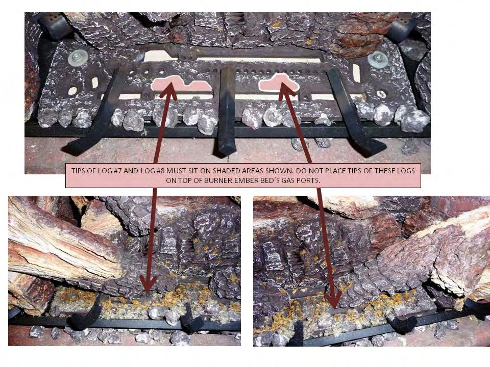
27 26 PLACE SMALL COALS ON TOP OF FLOOR BRICK PANELS AND CLOSE TO GRATE BOTTOM TO SIMULATE A COAL BED.


28 BEFORE YOU BEGIN Read this entire manual before you use your new fireplace insert(especially the section Safety Precautions ). Failure to follow the instructions may result in property damage, bodily injury, or even death. Remote Control Transmitter Functions NOTE: The Wall Receiver will beep once every time a Remote Transmitter Key is pressed, signaling that the command has been received. Identify the four function buttons on the Remote Transmitter: 1. ON/OFF KEY: This button turns the system ON or OFF. When this button is pressed and the system is OFF, the pilot light will stay ON if the Standing Pilot Switch is in the ON position. 2. THERMOSTAT KEY: This button, when pressed after the ON/OFF KEY is pressed and the system is ON, will allow the selection of three modes: Manual Operation, Normal Thermostat and Smart Thermostat. a. Manual Mode: In this mode, the room temperature is ignored and the fireplace can be turned ON indefinitely. The room temperature rise has no effect on this mode. All other functions such as fan speed control, flame height control, secondary burner On/OFF control and Accent Light ON/OFF controls will be manually controllable. b. Normal Thermostat: In this mode, the fireplace will stay functioning until the room temperature increases 1 o F above the Set Point Temperature. To increase the Set Point Temperature, Press the UP button until the desired temperature is displayed in the SET POINT TEMPERATURE window. The fan will turn on 5 minutes after fireplace startup and will turn off 12-1/2 minutes after the flames turn off, in this mode. The flame height can be adjusted while the fireplace is functioning, fan speed can be adjusted after 5 minutes of startup. Secondary burner can be turned On or Off at any time after startup. The Accent Light can be turned on or off any time after startup. c. Smart Thermostat: In this mode, all other functions except the flame height adjustment are allowed. Manual flame height adjustment is not allowed in this mode. The Smart Thermostat function adjusts the flame height in accordance to the difference between the set point temperature and the actual room temperature. As the room temperature gets closer to the set point temperature, the Smart Function automatically modulates the flame down. 3. UP/DOWN KEY: This key is used to increase or decrease the Set Point Temperatures, Flame Height and Fan Speed and to toggle between Accent Light ON/OFF and Secondary Burner ON/OFF. OFF MAX ON SMART F OFF 76 ON SMART F F Hi MANUAL MODE MAX Hi NORMAL THERMOSTAT 68 SMART MODE 4. MODE SELECTION KEY: This key is used to toggle between the various function icons: Set Temperature, Flame Height and Secondary Burner. 27
, ON (meaning normal Thermostat) or Smart (meaning Smart Mode). a.")
, the appliance will only ignite if the Set Temperature is greater than the Room Temperature. TO TURN OFF THE APPLIANCE, press the ON/OFF button.")


29 REMOTE TRANSMITTER OPERATING INSTRUCTIONS TO TURN ON THE APPLIANCE: 1. Press the ON/OFF button. The transmitter display will show all active icons on the screen. 2. Select the Thermostat Mode by pressing the Thermostat Key: OFF (meaning Manual Mode), ON (meaning normal Thermostat) or Smart (meaning Smart Mode). a. In OFF (Manual Mode), the appliance will ignite and start on HI. b. In ON (Normal Thermostat Mode), the appliance will only ignite if the Set Temperature is greater than the Room Temperature. c. In SMART (Smart Mode), the appliance will only ignite if the Set Temperature is greater than the Room Temperature. TO TURN OFF THE APPLIANCE, press the ON/OFF button. MODE KEY: Pressing the MODE KEY toggles between the various available functions: Temperature Setting, Flame Height Setting and Secondary Burner On/Off. Temperature Setting: Press the Mode Key until the large Set Temperature is displayed. Pressing the Up or Down button once in this mode will increase or decrease the set temperature. Note that the large temperature display in the center of the screen is the Set Temperature. The smaller temperature display in the top right corner is the room temperature that the hand held transmitter has sensed. ON 67 F 70 Flame Height: 6 flame height Levels are available. While the Flame Height Icon is displayed, pressing the Up or Down button once will increase or decrease the flame height by 1 of 6 increments. In Manual Mode, if the flame height is at Level 1 and the Down button is pressed, all burners will turn OFF. If in IPI mode, the pilot light will also extinguish. If in Standing Pilot Mode, the pilot light will remain ON. Note: If in SMART model, the flame height function is not available for manual adjustment. In SMART mode, the flame height regulates automatically. In Thermostat mode, you will be able to reduce the flame height down to the Level 1 setting but you will not be able to turn the burner off. Fan Speed Control: The fan speed can be adjusted through six (6) speeds and OFF. To activate this function, press the MODE Key to index to the fan control icon. Use the UP/Down Arrow Key to turn ON, OFF or adjust the fan speed. A single beep will confirm reception of the command. Aux (Accent-Light): This function controls the Mendota Accent Light function. Pressing the UP key in this mode will TURN ON the Accent Light and Pressing the DOWN key will TURN OFF the Accent Light. A single beep will confirm reception of the command. Note: The Accent Light Dimmer control is on the right face or right edge of the surround. Turn the Dimmer Control Knob to dim or brighten the Accent Light. Once you set your desired brightness level, you may use the AUX function to turn the Accent Light On or Off at that preset level. Secondary Burner: This function controls the Secondary Burner s ON/OFF feature. Pressing the UP Key in this mode will TURN ON the Secondary Burner and Pressing the DOWN Key will TURN OFF the Secondary Burner. The flame level will not change when you turn the Secondary Burner On or Off. The flame level can only be changed in the Flame Level mode. 28
30 MANUAL BYPASS OF THE REMOTE SYSTEM If the remote transmitter is misplaced or lost, the appliance can be turned on manually by sliding the three position slider switch on the wall receiver to the ON position. This will bypass the remote control feature of the system and the appliance s main burner will turn on. The fan will run at its maximum speed and the Accent Light may turn on. To turn off the appliance, if the remote control is misplaced or lost, slide the three position slider switch on the wall receiver to the OFF Position. SLIDE SWITCH TO "OFF" TO TURN SYSTEM OFF. TEMPERATURE INDICATOR ( o F or o C) 1. Press the ON/OFF Key and Turn Off the Fireplace. 2. Simultaneously, Press both the MODE Key and the Thermostat Key. 3. Look at the LCD display to verify that your desired indicator ( o F or o C) is being displayed. If not, repeat step 2. KEY LOCK FUNCTION To prevent unsupervised children from operating the fireplace, a KEY LOCK function is provided with this remote control system. To activate the KEY LOCK function, simultaneously press the MODE KEY and the UP KEY. To deactivate the KEY LOCK function, simultaneously press the MODE KEY and the UP KEY. During KEY LOCK mode, none of the Keys will function. You must DEACTIVATE the system before you can use the Remote Transmitter. LOW BATTERY POWER DETECTION 1. Transmitter Batteries: The life span of the remote control transmitter batteries depends on various factors: quality of the batteries used, the number of ignitions of the appliance, the number of changes to the room thermostat set point, etc. When the Transmitter batteries are low, a Battery Icon will appear on the LCD display of the Transmitter before all battery power is lost. When the batteries are replaced, this icon will disappear. 2. Wall Receiver Batteries: The life span of the wall receiver batteries depend on the quality of the batteries used and how long the batteries have been installed in the wall receiver. These batteries are only utilized during power outages. Replace these batteries every heating season even if you have not experienced any power outages. Batteries drain slowly even when not in use. This is a normal characteristic of all batteries. OPERATING DURING POWER OUTAGES This electronic ignition system utilizes the supplied 110VAC power when it is available for all functions of this system. If the AC power is interrupted during a power outage, this system utilizes the batteries (installed in the Wall Receiver) as back-up batteries. During the power outage, the appliance s burners will function. In addition, Flame Height adjustment and Secondary Burner ON/OFF functions will be available. The Fan and Accent Light, which are wholly dependent on 110VAC power, will not function. This appliance is designed and tested to be operated during power outages. The overall efficiency of this appliance will be reduced by approximately 5% when the blower function is disabled during the power outage period. 29
31 FIRST TIME PILOT LIGHTING INSTRUCTIONS IMPORTANT: Be sure all items on "INSTALLATION CHECK OFF LIST" in the Installation Manual have been completed! CAUTION: If the pilot goes out, be sure to wait a minimum of five minutes before attempting to relight the pilot. Make certain that any manual gas supply shut-off valves located upstream of fireplace are open and the wall receiver and the remote control transmitter are in the "OFF" position. Make certain that the wall receiver harness is connected to the wall receiver properly. Synchronize Remote Transmitter and Receiver. See INITIALIZING THE REMOTE CONTROL SYSTEM, below. 1. Make certain that 110VAC power cord is connected to an electrical outlet. 2. Insert Batteries in the Wall Receiver (4 x AA) and the Remote Transmitter (3 x AAA). Note the polarity of batteries and insert as indicated on the battery compartment covers. 3. For the First Time Lighting, Remove the Glass Door. This is required to purge the gas line of air and to inspect the pilot lighting spark. Slide the wall receiver switch to REMOTE. Locate the Standing Pilot ON/OFF Switch. See Figure 1. Toggle Standing Pilot ON/OFF Switch to ON. You will hear a series of clicks and after a few seconds, you will hear sparking at the pilot spark electrode. DETAIL C MANUAL GAS SHUTOFF CONTROL RECEIVER & BATTERY HOLDER 7. Allow adequate time for the air in the gas-line to purge. The control system will stop sparking after 30 seconds if the pilot light does not light. After a 30 second delay the control system will start sparking again for 30 seconds more. If the pilot light does not light after the third 30 second spark event, the system will enter Lock-out mode. To unlock from Lock-out mode, slide Wall Receiver Switch to OFF, wait 30 seconds and slide back to Remote. Repeat this sequence until the pilot flame lights and the pilot is burning steadily. After you inspect the spark and the pilot lights, turn off the pilot switch and close the glass door. 8. Relight Pilot after closing glass door. WARNING: NEVER IGNITE MAIN BURNERS WITH GLASS DOOR REMOVED OR OPEN. Doing so will lead to damage to pilot flame sensor and spark electrode wire leads. 9. Slide switch on Wall Receiver to ON. All burners should ignite and run at high-fire if rear burner solenoid is in ON position from the factory. If rear solenoid is in off position the rear burner will not ignite. Use the Remote System to turn rear burner ON. Slide Wall Receiver switch to REMOTE after 15 seconds. Burner Flames will extinguish. 10. Perform gas inlet and outlet pressure tests and leak tests on field installed gas fittings and factory installed fittings in the gas valve compartment, at this time. Note: Burners must be ON to check outlet pressures and to leak test gas train fittings upstream of main gas valve. INITIALIZING THE REMOTE CONTROL SYSTEM (Synchronizing Receiver and Transmitter) STANDING PILOT LIGHT ON/OFF SWITCH 1. Place 3-position slider switch in Wall Receiver in the Remote position. 2. Locate PRG key on Wall Receiver Face. Use the tip of a pen/pencil or a wire clip to push the PRG button. The receiver will beep 3 times indicating that it is ready to synchronize with a Remote Transmitter. 3. Push the ON key on the Remote Transmitter. The receiver will beep 4 times to indicate that the Transmitter s command is accepted and sets to the particular code of that Transmitter. The system is now initialized. NOTE: Use this Synchronizing procedure every time the batteries are replaced in the Receiver or the Transmitter. WALL RECEIVER BATTERY COMPARTMENT LID 3-POSITION SLIDER SWITCH PRG PRG KEY REMOTE TRANSMITTER BLUE LCD DISPLAY ON/OFF KEY THERMOSTAT SELECTION KEY UP/DOWN SELECTION KEY MODE SELECTION KEY 30
32 IPI/STANDING PILOT SYSTEM INFORMATION REMOTE CONTROL WALL RECEIVER Supply voltage 4.5V (three 1.5V AAA batteries) 6.0V (four 1.5V AA batteries) Ambient temperature ratings o F (0 50 o C) o F (0 60 o C) Radio Frequency 315 MHz 315 MHz ATTENTION! The transmitter and receiver are RADIO FREQUENCY DEVICES. Placing the receiver in or near metal may severely reduce the signal range. Turn off the main gas supply of the appliance during installation or maintenance of the receiver. Place the receiver s 3-position slider switch in the off position during installation or maintenance. Turn off main gas supply to the appliance prior to removing or reinserting the batteries in the receiver. During appliance installation/maintenance or in case of remote control malfunction, turn off electrical supply to this appliance and remove the batteries from the wall receiver battery compartment. Contact technical service. Intermittent Pilot Light and Standing Pilot Light Features This gas fireplace Insert is equipped with an electronic ignition System that first lights a pilot light then uses the pilot light to ignite the main burners. The pilot light can be set in the Standing Pilot mode to allow the pilot light to remain on indefinitely by toggling the Standing Pilot Switch to the ON position. If the Standing Pilot Switch is toggled to the OFF position, the pilot light will only light and remain ON while the main fireplace burners are operating. NOTE: Before inserting batteries into the Remote Receiver s battery compartment, toggle the Pilot Light ON/OFF switch to the OFF position. Toggle the switch DOWN to OFF. If the Pilot Light ON/OFF switch is left in the ON position, the pilot light will start sparking as soon as the batteries are inserted and the system may Lock-Out if the gas line is turned to off. IPI Mode: This mode turns the pilot light OFF when the fireplace is not functioning and only lights the pilot light automatically when a call for heat is made by the remote control. Standing Pilot Mode: If the Standing Pilot Switch is toggled to ON, the pilot light will ignite and remain ON as long as the Standing Pilot Light Switch is in the ON position. NOTE: Mendota Fireplaces recommends that the Standing Pilot Mode be used during the winter months when external temperatures fall below 50 o F. This will keep the fireplace chimney heated for proper updraft during burner ignition and it will also eliminate excessive condensation of exhaust vapors on the door glass. Further, leaving the fireplace in the Standing Pilot Mode will keep the fireplace body warm and eliminate cold drafts and heat loss to the cold air that is trapped inside the firebox. ON OFF MANUAL GAS SHUTOFF CONTROL RECEIVER & BATTERY HOLDER STANDING PILOT LIGHT ON/OFF SWITCH 31

33 FV-44i GAS IGNITION SYSTEM WIRING DIAGRAM 32

34 MAINTENANCE 1. ANNUAL MAINTENANCE OF MENDOTA UNITS IS REQUIRED. The following procedures must be performed each year by a Mendota approved service person. NOTE: Any adjustments to burner, pilot or logs must be done by a qualified Mendota service person. A. Clean all lint and dust build-up around the control. Inspect the condition of any wiring under the burner for melting or damage. B. Remove logs & coals and clean away any foreign matter (lint, Carbon, etc.) on the burner and logs. Be sure the burner ports are "open". Clean the pilot and under side of the logs for any Carbon deposits. NOTE: Logs should be visually checked for Carbon "build-up". If carbon deposits are visible on logs, unit should be turned off and Mendota service person contacted. Be sure logs are re-installed per instructions on PAGE 34. C. Check condition of glass door gasket, gasket must seal tightly over firebox, replace if necessary. D. Periodically check to verify that the vent system and vent cap are open and free of blockage. E. Before re-installing glass, have qualified service person check the operation of the pilot with millivolt meter and cycle the burner per LIGHTING INSTRUCTIONS (see PG. 43). Pilot must read a minimum of 460 millivolt. Be sure all items in LIGHTING and INSTALLATION "check off lists are completed. 4. The viewing glass should be cleaned periodically. Exterior glass 1" MIN. surface may be cleaned with cleaner as desired. To clean Interior glass surface, use Kel Kem polish plus" (part # ) or comparable product. Do not use oven cleaner or abrasive cleaners to clean glass. Do not clean when glass is hot. 5. Periodic visual check of pilot flames is required. Pilot Flame must overlap Flame Sensor and burner ignition ports at all times. 1" MIN. 6. Periodic visual check of main burner s rear and front flames is required. BURNER FLAMES GENERAL HEIGHTS REFERENCE DIAGRAM 1" MIN. HOOD FLAME SENSOR SPARK ROD 33
35 NATURAL TO LP GAS CONVERSION Kit # HA for Mendota Model FV-44i This conversion kit shall be installed by a qualified service agency in accordance with the manufacturer s instructions and all applicable codes and requirements of the authority having jurisdiction. If the information in these instructions is not followed exactly, a fire, explosion or production of carbon monoxide may result causing property damage, personal injury or loss of life. The qualified service agency is responsible for the proper installation of this kit. The installation is not proper and complete until the operation of the converted appliance is checked as specified in the owner instructions supplied with the kit. Motorized LP Pressure Regulator [ "WC] # Caution: The electrical supply to the fireplace must be turned off prior to performing the conversion. The gas supply must be shut off prior to disconnecting the electrical power. ORIFICE SIZES REQUIREMENT: Burner Orifices # [54 DRILL] # [55 DRILL] LP Pilot Orifice [# ] REMOVE LOG GRATE LIFT UP AND REMOVE FLOOR PANELS REMOVE SCREWS FIRST. FLOOR PANELS A Natural Gas to LPG conversion kit #HA must be ordered and installed to convert the FV-44i Fireplace to burn LPG. LP Conversion Kit # HA contains the following parts: One Motorized LP Pressure Regulator # , One LP Pilot Orifice Thimble # , and two Cap Orifices (drill #54 and drill #55). Recommended Procedure to Convert This Fireplace To Burn LPG This Fireplace Insert arrives from the factory ready to burn Natural Gas. If you intend to burn LPG, it is highly recommended that you convert this fireplace and its Pressure Regulator, Pilot Orifice Thimble and Burner Orifices prior to placing this fireplace in its fireplace cavity. See diagrams, on this page, and follow these instructions to prepare this fireplace for conversion to LPG. 1. Using a ¼ Hex Driver, remove 4 screws that secure the Log Grate in place. Remove Grate from Firebox. 2. Remove the Floor Brick Panels by lifting them out of the firebox. 3. Remove the left-side access panel mounted to the left outer skin and lay down gently without disconnecting any wires of internal components. 34


36 WARNING: It is of the utmost importance that the correct burner orifices be installed for both the rear and front burners. It is highly recommended that you remove the left side blower assembly and the left side exterior controls box before attempting to replace the pressure regulator. 1. Turn off gas supply at the appliance service valve. 2. See diagrams on this page and identify the Pressure Regulator on the Valve Body. 3. Using a Torx T20 or a slotted screwdriver, remove 2 screws that secure the NG Pressure Regulator to the gas valve body and remove NG Pressure Regulator, see following page. 4. Install the new LP Pressure Regular onto the gas valve body in the same position and orientation as the NG Pressure Regulator you removed in Step 2, above. The LP Pressure Regulator can only be mounted in one position. Secure the LP Pressure Regulator in place. Tighten down. 5. Remove both Rear and Front Burners. Locate and Identify the Rear Burner Orifice Spud and the Front Burner Orifice Spud. Both Front and Rear Orifice Spuds are removed and installed using a ½ deep well socket and ratchet. 6. Install Rear Burner Orifice # (#54 drill) for the Rear Burner. Tighten down securely. 7. Install Front Burner Orifice # (#55 drill) for the Front Burner. Tighten down securely. Install pilot orifice thimble # (.014 ) see Figure 25 for location. To remove Pilot Hood, use a screw driver to pry open the Wire Clip that is located at the base of the Pilot Hood. Pull Upward and remove pilot hood. Use an Alan wrench to remove NG Pilot Orifice. (Pilot orifice thimble is located inside pilot hood base). 8. Install LP Pilot Orifice. Tighten down using an Alan wrench. Replace Wire Clip in its original position. 9. Push Pilot Hood down into base until it snaps in place. VIEW FROM OUTSIDE FIREBOX PRESSURE REGULATOR Pull Pilot Hood UP and lift UP off the base. WIRE CLIP. 55 Use an Alan Wrench To loosen and remove NG Pilot Orifice. Install LP Pilot Orifice, Tighten Down. urner Orifices [#54 X1] [#55 X1] LP Pilot Orifice 54 ORIFICE WASHERS (2) 3/8" COMP X 1/8NPT BRASS FITTING MOTORIZED PRESSURE REGULATOR REAR ORIFICE INSIDE HERE. FRONT ORIFICE INSIDE HERE. PILOT LIGHT HOOD 35

37 LP PRESSURE REGULATOR CONVERSION INSTRUCTIONS WARNING: Failure to position the parts in accordance with these diagrams or failure to use only parts specifically approved with this appliance may result in property damage or personal injury. 36

38 LP GAS PRESSURE REQUIREMENTS Inlet and manifold gas pressure checking taps are located on gas valve. These ports are only accessible from the outer left side of the fireplace. A qualified installer shall take pressure measurements at these ports to verify and set the correct gas pressures during the LP Kit installation and before facia materials are installed over the front of this fireplace. Manifold pressure must be taken at the MANIFOLD PRESSURE" tap and inlet pressure at the "INLET PRESSURE" tap with the burner operating by a qualified installer. DESIRED INLET PRESSURE MINIMUM INLET PRESSURE MAXIMUM INLET PRESSURE MANIFOLD OUTLET PRESSURE AIR SHUTTER POSITION L.P. GAS 11.0" W.C. (2.75 kpa) 11" W.C. (2.75 kpa) 13.0" W.C. (3.24 kpa) 10.0" W.C. (2.5 kpa) 1/4" OPEN MIN. (5 mm) REGULATE THE FLAME HEIGHT TO "HIGH" POSITION. OUTLET GAS PRESSURES MAY VARY PLUS OR MINUS 5%. LPG PROPER INPUT RATES: With the proper orifices installed, as specified above, this fireplace utilizing LP Gas will have a maximum input rate of 40,000 Btu/Hr. LEAK TESTING REQUIREMENTS Prior to completing the conversion process, check for gas leaks with soap and water solution at all plumbing joints prior to placing this appliance into operation. It is recommended that all gas-plumbing joints, factory installed and field installed are checked for leaks. PILOT FLAME AND MAIN BURNER RELATIONSHIP VERIFICATION Prior to completing the conversion process, the qualified Figure 1: Pressure Test Port service technician must, light the pilot light and verify the relationship between the pilot light flames and the main burners. The pilot light flames directed towards the propagation ports on the rear and front burner must overlap the propagation ports on the burners. The pilot light flames must be a minimum of ¾ long and must overlap the propagation ports on both the rear and front burners as shown in the diagram, below. Verify that the burner tubes ignite quickly and the burner flames propagate smoothly along the entire length of the burners. PILOT FLAME LENGTH ADJUSTMENT If the pilot light flame length is too short and the system does not maintain a standing pilot, a qualified installer may increase the length of the pilot light flames to meet the two requirements: Minimum pilot light length to maintain a standing pilot light and the pilot light flames must be long enough to overlap the front and rear burner ports. 1" MIN. 1" MIN. Pilot Flame must overlap Burner Ports 1" MIN. 37
Full View Direct Vent Gas Fireplace Insert With Premium Texture Fiber Logs Combustion System INSTALLATION & OPERATING INSTRUCTIONS
 Full View Direct Vent Gas Fireplace Insert With Premium Texture Fiber Logs Combustion System INSTALLATION & OPERATING INSTRUCTIONS MODEL NO. FV44i-PF2 DOCUMENT: FV44i-PF2-0215 P/N 85-03-00886 Do not store
SIERRA RADIANT HEAT MAJESTIC OAK VENTED GAS LOG KIT INSTALLATION AND OPERATING INSTRUCTIONS
 SIERRA RADIANT HEAT MAJESTIC OAK VENTED GAS LOG KIT INSTALLATION AND OPERATING INSTRUCTIONS WARNING: If the information in this manual is not followed exactly, a fire or explosion may result causing property
Models #CSK-31 #CSK-31-RF. CHASKA Direct Vent Gas Fireplace Insert INSTALLATION & OPERATING MANUAL
 WARNING: If the information in these instructions are not followed exactly, a fire or explosion may result causing property damage, personal injury or loss of life. Models #CSK-31 #CSK-31-RF CHASKA Direct
Installation Instructions
 Installation Instructions Models: ODGO324-MTCH, Grand Oak Match Light Gas Log Sets Installation and service of this appliance should be performed by qualified personnel. Hearth & Home Technologies suggests
Models #CSK-335 #CSK-335-RF. CHASKA - XL Direct Vent Gas Fireplace Insert INSTALLATION & OPERATING MANUAL
 WARNING: If the information in these instructions are not followed exactly, a fire or explosion may result causing property damage, personal injury or loss of life. Models #CSK-335 #CSK-335-RF CHASKA -
MODELS LFP4218/LFP6018 TOP VENT GAS FIREPLACE
 MODELS LFP4218/LFP6018 TOP VENT GAS FIREPLACE PFS APPROVED FOR NATURAL GAS OR PROPANE GAS Z21.50-2014 If your plans do not allow for the venting system as outlined previously in the installing chimney/vent
Heat-N-Glo Fireplace. Installers Guide. Model: AT-GRAND
 Heat-N-Glo Fireplace Model: AT-GRAND Installers Guide Patents Pending Underwriters Laboratories Listed WARNING: IF THE INFORMATION IN THESE INSTRUCTIONS IS NOT FOLLOWED EXACTLY, A FIRE OR EXPLOSION MAY
616 GSR2 Insert (with screen) Owner s Manual
 Owner s Manual") 616 GSR2 Insert (with screen) Owner s Manual WARNING: FIRE OR EXPLOSION HAZARD Failure to follow safety warnings exactly could result in serious injury, death, or property damage. - Do not store or use
616 GSR2 Insert (with screen) Owner s Manual WARNING: FIRE OR EXPLOSION HAZARD Failure to follow safety warnings exactly could result in serious injury, death, or property damage. - Do not store or use
Installation/Operating Instructions
 Installation/Operating Instructions Models: 4072-180 24 NG 4072-182 30 NG Outdoor Hearth Kit DO NOT DISCARD INSTALLER: Leave this manual with party responsible for use and operation. OWNER: Retain this
M-27 INSTALLATION & OPERATING INSTRUCTIONS MANUAL DOCUMENT NO. M
 CHELSEA OPEN HEARTH TRUE ARCHED GAS DIRECT VENT FIREPLACE Model M-27 INSTALLATION & OPERATING INSTRUCTIONS MANUAL DOCUMENT NO. M27-0308 Do not store or use gasoline or other flammable vapors and liquids
616 Diamond-Fyre GSR2 Insert (with screen) Owner s Manual
 Owner s Manual") 616 Diamond-Fyre GSR2 Insert (with screen) Owner s Manual WARNING: FIRE OR EXPLOSION HAZARD Failure to follow safety warnings exactly could result in serious injury, death, or property damage. - Do not
616 Diamond-Fyre GSR2 Insert (with screen) Owner s Manual WARNING: FIRE OR EXPLOSION HAZARD Failure to follow safety warnings exactly could result in serious injury, death, or property damage. - Do not
OPERATING INSTRUCTIONS MANUAL (Please retain for future reference) FVN/P-400 INDIRECT FIRED SPACE HEATERS
 FVN/P-400 INDIRECT FIRED SPACE HEATERS") OPERATING INSTRUCTIONS MANUAL (Please retain for future reference) For FVN/P-400 INDIRECT FIRED SPACE HEATERS CERTIFIED FOR USE IN CANADA AND U.S.A. As per Standard ANSI Z83.7/CSA 21.4 2000 Gas Fired Construction
OPERATING INSTRUCTIONS MANUAL (Please retain for future reference) For FVN/P-400 INDIRECT FIRED SPACE HEATERS CERTIFIED FOR USE IN CANADA AND U.S.A. As per Standard ANSI Z83.7/CSA 21.4 2000 Gas Fired Construction
Installation Instructions T 9822 Gas Dryer. en - US, CA. To prevent accidents
 Installation Instructions T 9822 Gas Dryer To prevent accidents en - US, CA and appliance damage read these instructions before installation or use. M.-Nr. 07 431 110 2 WARNING For your safety the information
HOMEOWNER S MANUAL. CONTEMPORARY LINEAR VENT-FREE GAS FIREPLACE ModELS
 HOMEOWNER S MANUAL Empire Comfort Systems has manufactured safe, reliable heating systems since 1932. We take pride in our reputation for quality products, backed by the best sales, service and distribution
27-DVIE22. Gas Fired Vented Room Heater (Direct Vent) USERS INSTALLATION OPERATION and MAINTENANCE MANUAL. S/N And up
 USERS INSTALLATION OPERATION and MAINTENANCE MANUAL. S/N And up") 27-DVIE22 Gas Fired Vented Room Heater (Direct Vent) S/N 270000 And up USERS INSTALLATION OPERATION and MAINTENANCE MANUAL WARNING: If the information in this manual is not followed exactly, a fire or
27-DVIE22 Gas Fired Vented Room Heater (Direct Vent) S/N 270000 And up USERS INSTALLATION OPERATION and MAINTENANCE MANUAL WARNING: If the information in this manual is not followed exactly, a fire or
#CSK-31-RF. CHASKA Direct Vent Gas Fireplace Insert INSTALLATION & OPERATING MANUAL
 Models #CSK-31 #CSK-31-RF CHASKA Direct Vent Gas Fireplace Insert INSTALLATION & OPERATING MANUAL WARNING: If the information in these instructions is not followed exactly, a fire or explosion may result,
Multi-Function Cooktop
 INSTALLATION GUIDE Multi-Function Cooktop Contents Wolf Multi-Function Cooktop.................... 3 Multi-Function Cooktop Specifications............ 4 Multi-Function Cooktop Installation...............
OPERATING INSTRUCTIONS MANUAL (Please retain for future reference) FVN/P-400 INDIRECT FIRED SPACE HEATERS
 FVN/P-400 INDIRECT FIRED SPACE HEATERS") OPERATING INSTRUCTIONS MANUAL (Please retain for future reference) For FVN/P-400 INDIRECT FIRED SPACE HEATERS CERTIFIED FOR USE IN CANADA AND U.S.A. As per Standard ANSI Z83.7/CSA 21.4 2000 Gas Fired Construction
OPERATING INSTRUCTIONS MANUAL (Please retain for future reference) For FVN/P-400 INDIRECT FIRED SPACE HEATERS CERTIFIED FOR USE IN CANADA AND U.S.A. As per Standard ANSI Z83.7/CSA 21.4 2000 Gas Fired Construction
Installation Manual. For Australian refrigerator models: N304M.3 (93 liter 3-way operation with LP gas, 240 volts AC, or 12 volts DC )
") Installation Manual For Australian refrigerator models: N304M.3 (93 liter 3-way operation with LP gas, 240 volts AC, or 12 volts DC ) N404M.3 (128 liter 3-way operation with LP gas, 240 volts AC, or 12
Installation Manual For Australian refrigerator models: N304M.3 (93 liter 3-way operation with LP gas, 240 volts AC, or 12 volts DC ) N404M.3 (128 liter 3-way operation with LP gas, 240 volts AC, or 12
Internet Version for Reference Only INDUCED DRAFT COMMERCIAL WATER HEATERS SUPPLEMENT INSTRUCTIONS TO PART #
 INDUCED DRAFT COMMERCIAL WATER HEATERS SUPPLEMENT INSTRUCTIONS TO PART #238-39387-00 THIS INSTRUCTION SUPPLEMENT IS ONLY INTENDED TO GIVE INSTALLATION INSTRUCTIONS AND INFORMATION RELATED TO THE INDUCED
INSTALLATION AND OPERATIONS GUIDE FOR GRAND CANYON GAS LOG FIRE PIT SERIES ONLY
 INSTALLATION AND OPERATIONS GUIDE FOR GRAND CANYON GAS LOG FIRE PIT SERIES ONLY Installation and service must be provided by a qualified installer, service agency or gas supplier Grand Canyon Gas Logs,
GPC PASTA PRO INSTALLATION & USER OPERATION MANUAL
 GPC-14/18/20 GPC PASTA PRO INSTALLATION & USER OPERATION MANUAL GPC-18 shown with optional rinse station. NOTICE! After installation of your equipment, immediately contact your local gas supplier to obtain
GAS COOKTOP INSTALLATION INSTRUCTIONS
 INSTALLATION AND SERVICE MUST BE PERFORMED BY A QUALIFIED INSTALLER. IMPORTANT: SAVE FOR LOCAL ELECTRICAL INSPECTOR'S USE. READ AND SAVE THESE INSTRUCTIONS FOR FUTURE REFERENCE. WARNING If the information
E30I Gas Insert - Log Set & Proflame IPI Valve OWNER S MANUAL PLEASE KEEP THESE INSTRUCTIONS FOR FUTURE REFERENCE WARRANTY REGISTRATION
 WARRANTY REGISTRATION IS QUICK AND EASY ONLINE: enviro.com E30I Gas Insert - Log Set & Proflame IPI Valve OWNER S MANUAL FOR YOUR SAFETY Do not store or use gasoline or other flammable vapours and liquids
SURE HEAT MANUFACTURING
 SURE HEAT MANUFACTURING Installation and Operating Instructions for NATURAL & L.P. GAS A.G.A. SINGLE & DUAL BURNER VENTED UNITS Model: RP (8,24,30)-N GO (8,24,30)-N GLO (8,24,30)-N WO (8,24,30)-N CO (8,24,30)-N
12.0 cu.ft., 2 way, 4-door, R.V. refrigerator with ice maker.
 Installation Manual For 1200ACXX models: For 120XAC-IMXX models: 12.0 cu.ft., 2-way, 4-door, R.V. refrigerator. 12.0 cu.ft., 2 way, 4-door, R.V. refrigerator with ice maker. The letter X, in the model
CATALINA FIRE TABLE ASSEMBLY INSTRUCTIONS
 CATALINA FIRE TABLE ASSEMBLY INSTRUCTIONS CSA Model 98300 DRF01000 Installer: Leave these instructions with consumer. Consumer: Keep these instructions for future reference. DANGER If you smell gas: 1.
INSTALLATION AND OPERATING MANUAL
 WARNING: If the information in these instructions is not followed exactly, a fire or explosion may result, causing property damage, personal injury or loss of life. MODELS: #PRC-36 / #PRC-36-RF PRINCETON
ASSEMBLY INSTRUCTIONS
 ASSEMBLY INSTRUCTIONS Installer: Leave these instructions with consumer. Consumer: Keep these instructions for future reference. WARNING: If the information in this manual is not followed exactly, a fire
Installation Requirements for Models:
 900 & 9100 Series Refrigerators Installation Requirements for Models: 9162 9163 9182 9183 962 963 982 983 WARNING Improper installation, adjustment, alteration, service, or maintenance can cause injury
GAS -FIRED VENTED ROOM HEATERS MODEL 61TV
 GAS -FIRED VENTED ROOM HEATERS MODEL 61TV INSTALLATION MANUAL NEW BUCK CORPORATION WARNING: Improper installation, adjustment, alteration,service or maintenance can cause injury or property damage. Refer
USERS INSTALLATION OPERATION and MAINTENANCE MANUAL. Installer: Please leave this manual with the appliance owner for future reference
 Optima 34 Gas Fired Vented Room Heater (Direct Vent) For use with Natural Gas or Propane* WARNING: If the information in this manual is not followed exactly, fire or explosion may result causing property
Service Manual Model 3163
 Service Manual Model 3163 Contents Important Safety Information.......... 1 Specifications.................. 2 General Information.............. 2 Direct Vent Requirements........... 2 Propane System................
OVATION SERIES FIRE TABLES ASSEMBLY INSTRUCTIONS
 OVATION SERIES FIRE TABLES ASSEMBLY INSTRUCTIONS CSA Model98900 DRS02403 Installer: Leave these instructions with consumer. Consumer: Keep these instructions for future reference. DANGER If you smell gas:
DVL GSR2 NB Insert Owner s Manual
 DVL GSR2 NB Insert Owner s Manual WARNING: FIRE OR EXPLOSION HAZARD Failure to follow safety warnings exactly could result in serious injury, death, or property damage. - Do not store or use gasoline or
USERS INSTALLATION OPERATION and MAINTENANCE MANUAL. Installer: Please leave this manual with the appliance owner for future reference
 Optima 34 34-DVI34N For Serial Number 42164 and up Gas Fired Vented Room Heater (Direct Vent) For use with Natural Gas or Propane* WARNING: If the information in this manual is not followed exactly, fire
SOUTHWEST FIREBIRD MFG SONORAN UNVENTED Model 36/42/48
 SOUTHWEST FIREBIRD MFG SONORAN UNVENTED Model 36/42/48 INSTALLATION INSTRUCTIONS PREFABRICATED MODULAR MASONRY- UNVENTED SONORAN 36/42/48TO BE USED WITH UNVENTED GAS LOGS. SAVE THIS BOOK This book is valuable.
INSTALLATION GUIDE Dual Fuel Ranges
 INSTALLATION GUIDE Dual Fuel Ranges Contents Wolf Dual Fuel Ranges......................... 3 Safety Instructions............................ 4 Dual Fuel Range Specifications.................. 5 Dual Fuel
ASSEMBLY INSTRUCTIONS
 ASSEMBLY INSTRUCTIONS CSA Model: 98910L Printed in China Installer: Leave these instructions with consumer. Consumer: Keep these instructions for future reference. WARNING: If the information in this manual
Heat-N-Glo. Installers Guide. Model: 8000TVC
 Model: 8000TVC Heat-N-Glo Installers Guide Underwriters Laboratories Listed WARNING IF THE INFORMATION IN THESE INSTRUCTIONS IS NOT FOLLOWED EXACTLY, A FIRE OR EXPLOSION MAY RESULT CAUSING PROPERTY DAMAGE,
INSTALLATION OPERATING, AND SERVICE INSTRUCTIONS FOR SUBURBAN DIRECT VENT SEALED COMBUSTION GAS HEATER MODEL GT-10D
 INSTALLATION OPERATING, AND SERVICE INSTRUCTIONS FOR SUBURBAN DIRECT VENT SEALED COMBUSTION GAS HEATER MODEL GT-10D FOR YOUR SAFETY FOR YOUR SAFETY IF YOU SMELL GAS: DO NOT STORE OR USE GASOLINE 1. OPEN
f i r e - p a r t s. c o m
 Optima 32-1 Gas Fired Vented Room Heater (Direct Vent) (SERIAL #3940 AND UP) For use with Natural Gas or Propane* * see page 4 for optional items shown with this WARNING: If the information in this manual
Installation and service must be provided by a qualified installer, service agency or the gas supplier.
 INSTALLATION AND OPERATION GUIDE FOR OLDE WORLD BASKET Vented Decorative Appliance For all models tested through PFS Corporation, to ANSI Z21.60-2003/CGA 2.26-2003, Decorative Appliance for Installation
INSTALLATION AND OPERATING MANUAL
 WARNING: If the information in these instructions is not followed exactly, a fire or explosion may result, causing property damage, personal injury or loss of life. MODEL: #56701 Thief River Falls - TRF
CINCINNATI, OH USA
 INSTRUCTION MANUAL Part No. 89731 Revised October 1997 CINCINNATI, OH 45241-4807 USA GAS SAFETY PRECAUTIONS Instructions on what to do when a user smells gas can be obtained from the local gas supplier.
SHERWOOD INDUSTRIES IS AN ENVIRONMENTALLY RESPONSIBLE COMPANY. THIS MANUAL IS PRINTED ON RECYCLED PAPER.
 SHERWOOD INDUSTRIES IS AN ENVIRONMENTALLY RESPONSIBLE COMPANY. THIS MANUAL IS PRINTED ON RECYCLED PAPER. PLEASE KEEP THESE INSTRUCTIONS FOR FUTURE REFERENCE OWNER S MANUAL WARRANTY REGISTRATION enviro.com/warranty
USERS INSTALLATION OPERATION AND MAINTENANCE MANUAL
 EURO 25 25-BVI20N BVI20N-3 Vented Gas Fireplace Insert Heating Appliance SN 13066 AND UP Do not store or use gasoline or other flammable vapors and liquids in the vicinity of this or any other appliance.
Installation Instructions Dual Fuel Ranges
 Installation Instructions Dual Fuel Ranges E30DF74EPS E36DF76EPS E48DF76EPS 5995447082 2 Safety IMPORTANT SAFETY INSTRUCTIONS Safety Precautions Do not attempt to install or operate your unit until you
Owner s Guide Installation & Operation
 Owner s Guide Installation & Operation Hot Top HHT Series Hestan Commercial Corporation 3375 E. La Palma Ave Anaheim, CA 92806 (888) 905-7463 RETAIN THIS MANUAL FOR FUTURE REFERENCE P/N 002130 REV 1 IMPORTANT
INSTALLATION INSTRUCTIONS AND OWNER S MANUAL
 INSTALLATION INSTRUCTIONS AND OWNER S MANUAL DRIFTWOOD LOG SET FOR UNVENTED GAS LOG HEATER OR VENTED DECORATIVE APPLIANCE MODELS LS18CD-1 LS24CD-1 LS30CD-1 GAS-FIRED LS24CD Shown INSTALLER: Leave this
Legend VENTED GAS FIREPLACE HEATERS
 MODEL 937XN FOR USE WITH NATURAL GAS Legend MODEL 937XP FOR USE WITH PROPANE VENTED GAS FIREPLACE HEATERS WARNING: If the information in this manual is not followed exactly, a fire or explosion may result
GAS COOKTOP MODELS: CTG365D, CTG305D, CTG304D TO REDUCE THE RISK OF FIRE, ELECTRIC SHOCK, OR INJURY TO PERSONS, OBSERVE THE FOLLOWING
 By CNP INDUSTRIES, INC. P.O. Box 18645 Anaheim, Ca 92817 (877) 387-6721 INSTALLATION INSTRUCTIONS GAS COOKTOP MODELS: CTG365D, CTG305D, CTG304D IMPORTANT: Before beginning installation please read these
CAUTION FOR YOUR SAFETY
 VENT-FREE GAS FIREBOX Model # PC32VFC & PC36VFC CAUTION FOR YOUR SAFETY WARNING: IF THE INFORMATION IN THIS MANUAL IS NOT FOLLOWED EXACTLY, A FIRE MAY RESULT CAUSING PROPERTY DAMAGE, PERSONAL INJURY, OR
WALL MOUNTED ELECTRIC FIREPLACE HEATER. Model # : Onyx Ivory Mirror OWNER S MANUAL. AC V 60Hz 1500W
 WALL MOUNTED ELECTRIC FIREPLACE HEATER Model # : 80001 Onyx 80002 Ivory 80008 - Mirror OWNER S MANUAL AC 110-120V 60Hz 1500W WARNING Read and understand this entire owner s manual, including all safety
OPERATING INSTRUCTIONS MANUAL (Please retain for future reference) FVN/P-400 INDIRECT FIRED SPACE HEATERS
 FVN/P-400 INDIRECT FIRED SPACE HEATERS") OPERATING INSTRUCTIONS MANUAL (Please retain for future reference) For FVN/P-400 INDIRECT FIRED SPACE HEATERS CERTIFIED FOR USE IN CANADA AND U.S.A. As per Standard ANSI Z83.7/CSA 21.4 2000 Gas Fired Construction
OPERATING INSTRUCTIONS MANUAL (Please retain for future reference) For FVN/P-400 INDIRECT FIRED SPACE HEATERS CERTIFIED FOR USE IN CANADA AND U.S.A. As per Standard ANSI Z83.7/CSA 21.4 2000 Gas Fired Construction
Service Manual For model N260 - a 2.4 cu. ft., 2-way refrigerator. For model N a 2.4 cu. ft., 3-way refrigerator.
 Service Manual For model N260 - a 2.4 cu. ft., 2-way refrigerator. For model N260.3 - a 2.4 cu. ft., 3-way refrigerator. NORCOLD, Inc. P.O. Box 4248 Sidney, OH 45365-4248 Part No. 619260A (4-98) Table
Repeat procedures for other side.
 Repeat procedures for other side. ASSEMBLY INSTRUCTIONS Installer: Leave these instructions with consumer. Consumer: Keep these instructions for future reference. CSA Model 98900 Printed in China DANGER
STONE RIVER. The White Mountain Log Collection: LSU24SF-2 Shown
 INSTALLATION Instructions AND Owner's Manual The White Mountain Log Collection: STONE RIVER Log Set for vented and UNVENTED MULTI-SIDED GAS LOG HEATER MODELS LSU18SF-2 LSU24SF-2 LSU30SF-2 LSU24SF-2 Shown
USERS INSTALLATION OPERATION AND MAINTENANCE MANUAL
 OPTIMA 22 Gas Fired Vented Room Heater (Direct Vent) For use with natural gas or propane* WARNING: If the information in this manual is not followed exactly, fire or explosion may result causing property
INSTALLATION AND OPERATING MANUAL
 WARNING: If the information in these instructions is not followed exactly, a fire or explosion may result, causing property damage, personal injury or loss of life. MINNETONKA Direct Vent Gas Fireplace
TO DO IF YOU SMELL GAS
 616 GSR2 Diamond-Fyre TM Insert Owner's Manual Tested and Listed by ANSI Z21.88 CSA 2.33 Direct Vent Fireplace Insert Masonry or Factory Built (Metal) Wood- Burning Fireplace Residential or Mobile Home
UVST (SMOOTH FACE) UVCST (HEAT CIRCULATING) INSTALLATION & OPERATING INSTRUCTIONS
 UVCST (HEAT CIRCULATING) INSTALLATION & OPERATING INSTRUCTIONS") UNIVERSAL VENTFREE FIREPLACE UVST (SMOOTH FACE) UVCST (HEAT CIRCULATING) INSTALLATION & OPERATING INSTRUCTIONS 36 DUAL-SIDED FIREPLACE TO BE USED WITH ANY APPROVED VENTFREE GAS LOGS SAVE THIS BOOK This
UNIVERSAL VENTFREE FIREPLACE UVST (SMOOTH FACE) UVCST (HEAT CIRCULATING) INSTALLATION & OPERATING INSTRUCTIONS 36 DUAL-SIDED FIREPLACE TO BE USED WITH ANY APPROVED VENTFREE GAS LOGS SAVE THIS BOOK This
O-T L. INSTALLER: Leave this manual with the appliance. CONSUMER: Retain this manual for future reference.
 HUSSONG MANUFACTURING CO., INC. INSTALLER: Leave this manual with the appliance. CONSUMER: Retain this manual for future reference. WARNING: FIRE OR EXPLOSION HAZARD Failure to follow safety warnings exactly
INSTALLATION OPERATION AND SERVICE MANUAL
 INSTALLATION OPERATION AND SERVICE MANUAL THE OLD SALEM COLLECTION VENT FREE REGENCY COAL BASKET complies with ANSI Z21.11.2 THIS ONLINE MANUAL IS FOR PLANNING PUPOSES ONLY. CAREFULLY READ BEFORE PURCHASING.
INSTALLATION INSTRUCTIONS AND OWNER'S MANUAL
 INSTALLATION INSTRUCTIONS AND OWNER'S MANUAL RAVENWOOD LOG SET FOR UNVENTED GAS LOG HEATER OR VENTED DECORATIVE APPLIANCE STANDARD MODELS ALS18RV-1 ALS24RV-1 ALS30RV-1 GAS-FIRED SELECT MODELS ALS24RVS-1
DVL GSR2 NB Insert Owner s Manual
 DVL GSR2 NB Insert Owner s Manual WARNING: FIRE OR EXPLOSION HAZARD Failure to follow safety warnings exactly could result in serious injury, death, or property damage. - Do not store or use gasoline or
Owner s Guide Installation & Operation
 Owner s Guide Installation & Operation Char Broiler HCH Series Hestan Commercial Corporation 3375 E. La Palma Ave Anaheim, CA 92806 (888) 905-7463 RETAIN THIS MANUAL FOR FUTURE REFERENCE P/N 002134 REV
f i r e - p a r t s. c o m
 INSTALLATION INSTRUCTIONS AND OWNER'S MANUAL INSTALLER: Leave this manual with the appliance. CONSUMER: Retain this manual for future reference. DIRECT VENT GAS Fireplace INSERT CONTEMPORARY DXL(30,35)IN91(N,P)-2
INSTALLATION & OPERATING MANUAL
 INSTALLATION & OPERATING MANUAL MODELS: #932 DIRECT VENT WALL-FURNACE #936 DIRECT VENT WALL- FURNACE U.S. Patents: #5.931.154 #6.004.493 IMPORTANT: READ INSTRUCTIONS CAREFULLY BEFORE INSTALLATION. FAILURE
ASSEMBLY INSTRUCTIONS
 ASSEMBLY INSTRUCTIONS CSA Model 99000 ARL00100 Installer: Leave these instructions with consumer. Consumer: Keep these instructions for future reference. DANGER If you smell gas: 1. Shut off gas to the
WARNING INSTALLATION INSTRUCTIONS AND OWNER'S MANUAL DIRECT VENT GAS FIREPLACE INSERT TRADITIONAL MODELS DXT(30,35)IN91(N,P)-2 UL FILE NO.
IN91(N,P)-2 UL FILE NO.") INSTALLATION INSTRUCTIONS AND OWNER'S MANUAL Installer: Leave this manual with the appliance. Consumer: Retain this manual for future reference. WARNING FIRE OR EXPLOSION HAZARD Failure to follow safety
INSTALLATION INSTRUCTIONS AND OWNER'S MANUAL Installer: Leave this manual with the appliance. Consumer: Retain this manual for future reference. WARNING FIRE OR EXPLOSION HAZARD Failure to follow safety
DVS GSR2 NB Insert Owner s Manual
 DVS GSR2 NB Insert Owner s Manual WARNING: FIRE OR EXPLOSION HAZARD Failure to follow safety warnings exactly could result in serious injury, death, or property damage. - Do not store or use gasoline or
OPERATING INSTRUCTIONS MANUAL (Please retain for future reference) FVN/P-400 INDIRECT FIRED SPACE HEATERS
 FVN/P-400 INDIRECT FIRED SPACE HEATERS") OPERATING INSTRUCTIONS MANUAL (Please retain for future reference) For FVN/P-400 INDIRECT FIRED SPACE HEATERS CERTIFIED FOR USE IN CANADA AND U.S.A. As per Standard ANSI Z83.7/CSA 21.4 2000 Gas Fired Construction
OPERATING INSTRUCTIONS MANUAL (Please retain for future reference) For FVN/P-400 INDIRECT FIRED SPACE HEATERS CERTIFIED FOR USE IN CANADA AND U.S.A. As per Standard ANSI Z83.7/CSA 21.4 2000 Gas Fired Construction
Operation & Maintenance Manual
 & Maintenance Manual Proflame 2 System NOTICE Read these instructions before use. WARNING Do not operate in presence of water dripping, spraying, rain, etc. ATTENTION - Turn OFF the main gas supply of
User Manual. 110 Cup (55 Cup Raw) Gas Rice Cooker. Model: 177GRCLP, 177GRCNAT 12/2018. Please read and keep these instructions. Indoor use only.
 Gas Rice Cooker. Model: 177GRCLP, 177GRCNAT 12/2018. Please read and keep these instructions. Indoor use only.") 110 Cup (55 Cup Raw) Gas Rice Cooker Intertek 5010781 Conforms to ANSI STD Z83.11-2016 Model: 177GRCLP, 177GRCNAT 12/2018 FOR YOUR SAFETY Do not store or use gasoline or other flammable vapors or liquids
110 Cup (55 Cup Raw) Gas Rice Cooker Intertek 5010781 Conforms to ANSI STD Z83.11-2016 Model: 177GRCLP, 177GRCNAT 12/2018 FOR YOUR SAFETY Do not store or use gasoline or other flammable vapors or liquids
For use with models: PGM304-1, versions M-B PGM365-1, versions M-E, M-F & M-G
 PGM-1 Cooktops For use with models: PGM304-1, versions M-B PGM365-1, versions M-E, M-F & M-G Install ation Instructions Part No. 65476 Rev. B Table of Contents Appliance Safety...1 Important Safety Instructions...2
DANGER HOMEOWNERS MANUAL. INSTALLER: Leave this manual with the appliance. CONSUMER: Retain this manual for future reference.
 HOMEOWNERS MANUAL INSTALLER: Leave this manual with the appliance. CONSUMER: Retain this manual for future reference. direct vent zero clearance gas fireplace heater series: DVCT40CFP95N-1 DVCT40CFP95P-1
S150 S300 CONSTRUCTION HEATERS. Rev: August 15, 2008 SERVICE AND MAINTENANCE MANUAL No PLEASE RETAIN FOR FUTURE REFERENCE PRODUCTS
 S150 & S300 CONSTRUCTION HEATERS Rev: 2.7.2 August 15, 2008 SERVICE AND MAINTENANCE MANUAL No. 934-6637 PLEASE RETAIN FOR FUTURE REFERENCE PRODUCTS A DIVISION OF HAUL-ALL EQUIPMENT LTD. 4115-18 Avenue
Hanover Outdoor Furniture IMPORTANT. If you have any problems with this product (missing or damaged parts, assembly issues, etc.),
,") Hanover Outdoor Furniture IMPORTANT If you have any problems with this product (missing or damaged parts, assembly issues, etc.), PLEASE DO NOT RETURN TO THE RETAILER/STORE from where you purchased the
Hanover Outdoor Furniture IMPORTANT If you have any problems with this product (missing or damaged parts, assembly issues, etc.), PLEASE DO NOT RETURN TO THE RETAILER/STORE from where you purchased the
Using it in an enclosed space can kill you.
 38 X 56 GAS FIRE PIT - OWNER S MANUAL Carlisle Chat Fire Table Base Model # 00GBC7 (6877B) Fits 6877A Carlisle Chat Fire Table Top For Propane and *Natural Gas (*See Page 7) Certified to CSA International
ASSEMBLY INSTRUCTIONS
 ASSEMBLY INSTRUCTIONS Installer: Leave these instructions with consumer. Consumer: Keep these instructions for future reference. CSA Model99000 BRH01000 DANGER If you smell gas: 1. Shut off gas to the
INSTALLATION & OPERATING INSTRUCTIONS
 INSTALLATION & OPERATING INSTRUCTIONS MODEL #944 DIRECT VENT SEE-THRU / PIER GAS FIREPLACE See-Thru Model U.S. Patent Number: 5,931,154 U.S. Patent Number: 6,004,493 Pier Model Front view IMPORTANT: READ
SUPER HIGH EFFICIENCY WATER HEATERS SUPPLEMENT TO INSTRUCTION MANUAL P/N (Replaces pg. 2 in instruction manual.) CONGRATULATIONS!
 CONGRATULATIONS!") SUPER HIGH EFFICIENCY WATER HEATERS SUPPLEMENT TO INSTRUCTION MANUAL P/N 238-44219-00 (Replaces pg. 2 in instruction manual.) CONGRATULATIONS! You have just purchased one of the finest water heaters on
SUPER HIGH EFFICIENCY WATER HEATERS SUPPLEMENT TO INSTRUCTION MANUAL P/N 238-44219-00 (Replaces pg. 2 in instruction manual.) CONGRATULATIONS! You have just purchased one of the finest water heaters on
INSTALLATION & OPERATING MANUAL
 INSTALLATION & OPERATING MANUAL MODEL: SP-36: SLIM PROFILE 36" DIRECT VENT GAS FIREPLACE US Patent Number 5,931,154 US Patent Number 6,004,493 IMPORTANT: READ INSTRUCTIONS CAREFULLY BEFORE INSTALLATION.
DO NOT DISCARD. Do not store or use gasoline or other flammable vapors and liquids in the vicinity of this or any other appliance.
 INSTALLATION AND OPERATION MANUAL INSTALLER: LEAVE THIS MANUAL WITH THE APPLIANCE. CONSUMER: RETAIN THIS MANUAL FOR FUTURE REFERENCE. Quality Fireplaces for Life DO NOT DISCARD DIRECT VENT FIREPLACE This
INSTALLATION, OPERATION, AND MAINTENANCE MANUAL 31-DVIM33N-2
 INSTALLATION, OPERATION, AND MAINTENANCE MANUAL 31-DVIM33N-2 GAS FIRED VENTED ROOM HEATER (DIRECT VENT) S/N 200285 AND UP This appliance may be installed in an aftermarket permanently located, manufactured
EURO BVI20N. BVI20N-2 Vented Gas Fireplace Insert Heating Appliance SN AND UP U INSTALLATION OPERATION AND MAINTENANCE MANUAL
 EURO 25 25-BVI20N BVI20N-2 Vented Gas Fireplace Insert Heating Appliance SN 13066 AND UP Do not store or use gasoline or other flammable vapors and liquids in the vicinity of this or any other appliance.
INSTALLATION AND OPERATING MANUAL
 INSTALLATION AND OPERATING MANUAL INSTALLER: LEAVE THIS MANUAL WITH THE APPLIANCE. CONSUMER: RETAIN THIS MANUAL FOR FUTURE REFERENCE. GAS FIREPLACE WARNING: This product must be installed by a licensed
GAS COOKTOP INSTALLATION INSTRUCTIONS BEFORE YOU BEGIN. IMPORTANT Save these instructions for local electrical inspector s use.
 GAS COOKTOP INSTALLATION INSTRUCTIONS Please read this guide thoroughly before installation. To contact LG Electronics, 24 hours a day, 7 days a week: 1-800-243-0000 (U.S.A.) 1-888-542-2623 (Canada) Or
Installation Instructions
 Installation Instructions Models: GO-IPI-NG or LP-HK GO0-IPI-NG or LP-HK GO-IPI-NG or LP-HK GO-IPI-NG or LP-HK GO0-IPI-NG or LP-HK Grand Oak Hearth Kits Installation and service of this appliance should
Installation instructions for the T 9820 Gas Dryer
 Installation instructions for the T 9820 Gas Dryer The T 9820 gas dryer is only approved for use in the USA and Canada. It is not approved for use in Mexico. To prevent accidents en - US, CA and machine
Owner s Manual Installation and Operation
 Owner s Manual Installation and Operation Model: ST-42TVFL-IPI CAUTION DO NOT DISCARD THIS MANUAL Important operating Read, understand and follow Leave this manual with and maintenance these instructions
SERIAL # ESPRIT INSTALLATION AND OPERATING INSTRUCTIONS MODEL: ESPR.BODYB SERIES: B ESPRIT ZERO CLEARANCE BALANCED FLUE FIREPLACE
 INSTALLER: Leave this manual with the appliance. CONSUMER: Retain this manual for future reference. WARNING: If the information in these instructions are not followed exactly, a fire or explosion may result
SAFE DRINKING WATER AND TOXIC ENFORCEMENT ACT
 Installation instructions for your new Spacemaker Laundry WSM2780 Gas Before you begin Read these instructions completely and carefully. IMPORTANT OBSERVE ALL GOVERNING CODES AND ORDINANCES. Note to Installer
MODEL 34 MAY BE INSTALLED IN A SOLID FUEL BURNING FIREPLACE, AS A ZERO CLEARANCE FIREPLACE OR WITH AN OPTIONAL SURROUND.
 MODEL 34 MAY BE INSTALLED IN A SOLID FUEL BURNING FIREPLACE, AS A ZERO CLEARANCE FIREPLACE OR WITH AN OPTIONAL SURROUND. WARNING: If the information in this manual is not followed exactly, a fire or explosion
Installation Instructions
 Installation Instructions for Dryers Inside... Dimensions... Before You Start... 4 Installing the Dryer... 5 Installer Checklist... Back Cover Date Purchased Model Number Serial Number Keep these instructions
INSTALLER: Leave this manual with the appliance. CONSUMER: Retain this manual for future reference.
 UNVENTED (VENT-FREE) GAS LOG HEATER OWNER S OPERATION AND INSTALLATION MANUAL Remote-Ready Models VUL18/24/30/36(N,P)R Thermostatically-Controlled Models VUL18/24/30/36(N,P)T Remote-Ready Models Also Design-Certified
MODEL 329 MAY BE INSTALLED IN A SOLID FUEL BURNING FIREPLACE, AS A FREESTANDING FIREPLACE OR WITH AN OPTIONAL WOODEN SURROUND.
 MODEL 329 MAY BE INSTALLED IN A SOLID FUEL BURNING FIREPLACE, AS A FREESTANDING FIREPLACE OR WITH AN OPTIONAL WOODEN SURROUND. VENT-FREE WARNING: If the information in this manual is not followed exactly,
INSTALLATION INSTRUCTIONS FOR FREESTANDING DUAL FUEL
 INSTALLATION AND SERVICE MUST BE PERFORMED BY A QUALIFIED INSTALLER. IMPORTANT: SAVE FOR LOCAL ELECTRICAL INSPECTOR'S USE. READ AND SAVE THESE INSTRUCTIONS FOR FUTURE REFERENCE. If the information in this
southbend A MIDDLEBY COMPANY INSTALLATION AND OPERATION MANUAL CG214 (E) CG314 (E) CG414 (E) CG220 (E) CG320 (E) CG325 (E) GAS BOILERS MODELS:
 CG314 (E) CG414 (E) CG220 (E) CG320 (E) CG325 (E) GAS BOILERS MODELS:") INSTALLATION AND OPERATION MANUAL GAS BOILERS MODELS: CG214 (E) CG314 (E) CG414 (E) CG220 (E) CG320 (E) CG325 (E) southbend A MIDDLEBY COMPANY 1100 Old Honeycutt Road Fuquay-Varina, NC 27526 (919) 552-9161
INSTALLATION AND OPERATION MANUAL GAS BOILERS MODELS: CG214 (E) CG314 (E) CG414 (E) CG220 (E) CG320 (E) CG325 (E) southbend A MIDDLEBY COMPANY 1100 Old Honeycutt Road Fuquay-Varina, NC 27526 (919) 552-9161