Installation / Operation Manual
|
|
|
- Wilfrid Stafford
- 5 years ago
- Views:
Transcription


1 Signature 3 Installation / Operation Manual
2 ABOUT YOUR SYSTEM The Sidekick uses the air we breath to naturally reduce the effects of Iron, Manganese and Sulfur Gas. By introducing oxygen to the water, contaminants chemically change to a physical particle that can be mechanically filtered out of this water. This natural process called Oxidation, is usually accomplished in other systems by using chemicals such as chlorine or potassium permanganate. Since the Sidekick does not use chemicals to treat the water, maintenance and chemical byproducts associated with these types of systems is eliminated. The energy required to operate this system is provided by using extra power that is available in your well pump to inject free air into the water. There are several normal side effects that may or may not occur when water is treated in this manner: 1. Cloudy or milky appearance to the treated water. This side effect is usually more pronounced when the Iron, Manganese or Sulfur Gas levels are low. Since the Sidekick uses oxygen for the treatment of these contaminants, it can be expected to have some amount left over in the treated water. The higher the contamination levels are, the less oxygen there will be. It is the oxygen that gives the cloudy or milky appearance. Once the faucet is opened and the water is drawn, pressure is released and allows the oxygen to escape. This usually will take from a few seconds to a minute depending on the amount of oxygen and the pressure. This noticeable side effect tells you the system is working properly and also will actually enhance the palatability of the water. It s oxygen that gives water it s fresh, crisp taste. 2. Sputtering or slight coughing from the hot water side faucets. This is a normal phenomenon that usually occurs first thing in the morning. As the highly oxygenated Sidekick water is exposed to heat in the hot water tank a small amount of oxygen will separate. The longer the water is allowed to sit in the hot water tank, the more this will be noticed. Usually, this will only occur if the hot water is allowed to sit idle for eight (8) hours or more. Consequently, when hot water is drawn after an extended period of no water use, a slight sputtering or coughing may be experienced for a few seconds. If this causes the hot water to splash out of the sink, the problem is reduced by simply turning on the cold water first and blending in the hot for several seconds. If there is a large amount of free air noticed on the cold water side, there is a possible malfunction of the system and your Clearion Dealer should be contacted to service the unit. 2

3 General Specifications... Page 4 Installation Requirements... Page 5 Set Up Utilizing Bluetooth App... Page 9 Set Up Using Buttons and Display on Valve... Page 12 Master Programming... Page 15 Control Valve Power Assembly... Page 17 Valve Body Assembly... Page 19 Tank Assembly... Page 21 Bypass Assembly... Page 23 Service Instructions... Page 24 Troubleshooting... Page 26 Error Codes... Page 27 Warranty... Page 28 Register Your Product Online at 3
4 Specifications General Specifications SK15 SK25 Smart Blend 1.5 cu. ft. 2.5 cu. ft. Gravel Underbedding 20 lbs. 50 lbs. Mineral Tank 10 X X 54 Service Flow Rate - Continuous (GPM) 5 8 Service Flow Rate - Intermittent (GPM) 7 10 Backwash Flow Rate (GPM) Gallons Used / Backwash Space Required (D x W x H inches) 10 X 21 X X 24 X 61 Approximate Shipping Weight General Specifications SK15S SK25S Catalytic Carbon 1.5 cu. ft. 2.5 cu. ft. Gravel Underbedding 20 lbs. 50 lbs. KDF Cubes 1.5 lbs 2.5 lbs Mineral Tank 10 X X 54 Service Flow Rate - Continuous (GPM) 5 8 Service Flow Rate - Intermittent (GPM) 7 10 Backwash Flow Rate (GPM) Gallons Used / Backwash Space Required (D x W x H inches) 10 X 21 X X 24 X 61 Approximate Shipping Weight WARNING Lubricants Do NOT use Vaseline, oils, hydrocarbon lubricants or spray silicone anywhere! Petroleum base lubricants will cause swelling of o-rings and seals. The use of other lubricants may attack plastic Noryl. It is recommended that Dow Corning silicone grease be used as a lubricant for all control valves. Dow Corning 7 Release Compound is used in the manufacture of Chandler Systems control valves. (Part # LT-150) Sealants Pipe dope and liquid thread sealers may contain a carrier that attacks some plastic materials. It is recommended that Teflon tape be used to seal plastic Noryl threaded fittings. 4

5 Installation Installation Requirements Make sure you have level floor position ahead of piping into water heater. Unit must be installed at least 10 feet ahead of the inlet to a water heater to prevent damage due to back-up hot water. DO NOT install the unit in an area of direct sunlight or where freezing temperatures may occur! Locate the unit near an unswitched, 120 volt / 60 Hz grounded electrical outlet. Check for distance and proper drain installation (e.g. floor drain, washing machine standpipe). Determine type and size of piping required for filter connection (e.g. copper, galvanized, PVC plastic). Note: If household plumbing is galvanized and you intend to make the installation with copper (or vice versa), obtain di-electric unions to prevent dissimilar metal corrosion. Note Where the drain line is elevated above the control valve or exceeds 20 feet in length to reach the drain, use 3/4 I.D. drain line tubing instead of 1/2 I.D. Drain line tubing is not included. Caution: If sweat soldering copper pipe (remember to always use lead free solder and flux), cover yoke and bypass valve with wet rags to prevent heat damage to connections and control valve. If using PVC or plastic pipe, primers and solvent cements specifically recommended for use with potable water are required. Note: All plumbing lines not requiring filtered water should be connected upstream of the equipment installed. A one-way check valve must be installed between the secondary service line and inlet to the filter to prevent backflow. (See Typical Installation Diagrams.) Ozone Tube Ozone Complete (Sold Separately) Oxy -08NP Optional Oxyclean OXY-03 Ozone Complete Optional 5
6 Installation Installation Procedure - Water Supply Connection and Bypass Valve - To allow for filter servicing, swimming pool filling or lawn sprinkling, a manual Bypass Valve has been installed at the factory. The Bypass allows raw water to be manually routed around the filter. 1. Position filter at desired location for installation. If a water softener is to be installed, the filter should be positioned first and then the softener. (See Installation Diagrams.) 2. The filter media is shipped separately from the mineral tank. The tank must be loaded with media after tank has been placed at the desired location. A. Remove the tank closure by unscrewing from the tank. B. Use cap provided to place over top of distributor tube to prevent media from entering tube while filling. C. Place media funnel in hole on top of tank. D. Pour several gallons of water in the tank. (Fill tank about 1/3 full.) E. Pour in the required filter media. Gravel underbedding has been installed at the factory. The required quantity & type of media is listed in the filter specifications. F. After installing filter media, add the included pack of aeration balls or KDF cubes. G. After filling the tank with material, use a garden hose or several buckets to fill the tank with water. Note: This will permit the filtering media to become soaked while preparing the installation and will prevent the control valve from being plugged with floating media on initial backwash. H. Remove funnel and clean filter media from tank threads. I. Remove cap from distributor tube. J. Replace tank closure on mineral tank. 3. Turn OFF main water supply and OPEN nearest faucet to relieve pressure. 4. Cut main line and install appropriate elbows and extensions. Caution: Raised arrows located on the sides of control valve body and bypass valve indicate proper direction of water flow. Install inlet and outlet piping in direction of arrows. It is recommended that a vacuum breaker be installed on the inlet plumbing. - Drain Line Connection - 1. The drain line flow control assembly is pre-assembled for your convenience. Should you choose to hard plumb the drain line, please remove the barb fitting. The flow control housing can be removed by removing the clip and pulling straight out on housing. Note: When re-installing the drain line flow control housing, be sure you hear and feel the O-Ring pop into place before inserting the clip. 2. Install 1/2 I.D. drain line tubing (not included) from hose barb to an open drain. A 4 gap between end of the drain line and the open drain is required to prevent waste water backflow. Keep the drain line as short as possible. An overhead drain line can be used if necessary, but should discharge below the control valve. A syphon trap (taped loop) at the outlet of the drain line is advisable to keep the drain line full and assure correct flow during backwash. Elbows or other fittings must be kept at a bare minimum. Note: Where the drain line is elevated above the control valve or exceeds 20 feet in length, 3/4 I.D. drain line tubing should be used. 6

7 Installation - Electrical Connection - 1. Connect the power cord and plug power supply into a 115 volt / 60 Hz receptacle. Note : Do not plug into an outlet controlled by a wall switch or pull chain that could inadvertently be turned off Electronic Connections P = Power Supply B = Powered in Air Replenish Step Only (Cycle #1) P B S S = Powered for Entire Backwash Cycle - System Start Up Procedures - IMPORTANT NOTE: Tank should be filled with water and media must have been soaking for at least 1 hour before initial pressurization 1. After all plumbing and drain line connections have been made, turn main water supply back on and check for leaks. 2. Ensure that the bypass valve is in the BYPASS position, and then cycle the control valve to RAPID RINSE. Once the rapid rinse step is reached, slowly open the bypass valve to the service position, allowing water to flow down through mineral tank and out the drain line. Let it continue to run for the entire rapid rinse step (5 minutes). There may be colored water or media fines during this initial flow. 3. Once the rapid rinse ends, leave the system in service, and open a cold, treated water tap. Let water run for several minutes to allow air and any media fines to be released from the lines. Once air is evacuated and water runs clear, close the tap. NOTE: Any time media (other than very fine mineral on initial startup) is apparent in the service lines, it usually indicates one of the following problems: A. The unit is plumbed in backward allowing the media to be carried in the service line. B. The distributor tube inside the tank is not seated inside the valve or is damaged. 4. No further regeneration should be necessary at this time. If left at the default settings, the filter will automatically initiate an air replenish cycle each night and will backwash every six days. If desired, these settings can be changed in the main menu, or from the advanced settings screen in the Legacy View app. 7
8 Installation - Final Checkout - 1. Be certain that the bypass valve is in Service position and main valve is completely on. 2. Check electrical supply to be certain the cord is connected to an uninterrupted 115 volt outlet. 3. Be certain to REGISTER YOUR PRODUCT online at 4. Leave this manual with the homeowner. Important Notice - The plumbing system, piping, pressure tank, hot water tanks, softeners, etc. that have been exposed to iron bearing water may need to be cleaned of the precipitated iron that has been collected in them or iron bleed thru may be a problem. We suggest all tanks be drained and flushed thoroughly. 8
 enabled smart phone or tablet. 1.")


9 Set Up Utilizing Bluetooth App For simplified set up and control, please install the Legacy View on a compatible Bluetooth 4.0+ (BTLE) enabled smart phone or tablet. 1. Download and install the Legacy View app from the Google Play Store, Apple App Store 2. Open the Legacy View app Choose a valve device at any time from the list of available devices to connect to by clicking on it. If the valve you want to connect to doesn t show up, or there is a problem connecting to a device you can press the Scan for Devices button or the Legacy View logo at any time to refresh the list and start the process over. If the valve device is a BTLE valve and it has a password other than the default password, the first time you connect to it the app will ask you to enter the password. After entering it the first time you should not need to enter it again unless it changes. 3. BTLE Valve devices can be updated by the App. When the app is updated from the Google Play Store or the Apple App Store, it may contain an updated firmware program for the valve devices. These updates could contain new features or operational improvements. It is up to the user to allow these updates to be sent to the valve device. Uploading a new program takes approximately 1 minute. Dashboard NOTE: Consult your dealer before making any changes From the Dashboard, all items in ORANGE can be changed, while blue fields are informational only. If you are unsure about the function of the field click the for more information. 9
 1.")


10 Set Up Utilizing Bluetooth App 1. Change Time of day (Press set to set time automatically based on device time) 1. Set Backwash Frequency This sets the amount of days between backwash cycles. 1. Set Regeneration Time Example: For 2am, just type 2 and press OK. Advanced Settings NOTE: Consult your dealer before making any changes. We do not recommend changing Advanced Settings unless you have a good understanding of the system operation. From the Advanced Settings, all items in ORANGE with a set button can be changed. 10


 this device may not cause harmful interference, and (2) this device must accept any interference received, including interference that may cause")


11 Set Up Utilizing Bluetooth App Status and History From the Status and History, all items in ORANGE can be reset. Touch any table to explode a detailed list of the last log data 1. Start a regeneration or backwash cycle Option 1: Click the Regenerate Unit Now. Once a regeneration has been started, if you would like to force the unit into the next cycle step click Go to Next Regeneration Step. Option 2: Regenerate Unit at Next Regen Time button. This will take the system into a backwash cycle at the next regeneration time. FCC ID: Name of Grantee: Equipment Class: Notes: SWPLV-019 or SWPEV-019-BLE CHANDLER SYSTEMS, INC. Part 15 Low Power Communication Device Legacy View Valve This device complies with part 15 of the FCC Rules. Operation is subject to the following conditions: (1) this device may not cause harmful interference, and (2) this device must accept any interference received, including interference that may cause undesired operation. Changes or modifications not expressly approved by the party responsible for compliance could void the user s authority to operate the equipment. NOTE: This equipment has been tested and found to comply with the limits for a Class B digital device, pursuant to Part 15 of the FCC Rules. These limits are designed to provide reasonable protection against harmful interference in a residential installation. This equipment generates, uses and can radiate radio frequency energy and, if not installed and used in accordance with the instructions, may cause harmful interference to radio communications. However, there is no guarantee that interference will not occur in a particular installation. If this equipment does cause harmful interference to radio or television reception, which can be determined by turning the equipment off and on, the user is encouraged to try to correct the interference by one or more of the following measures: - Reorient or relocate the receiving antenna. - Increase the separation between the equipment and receiver. - Connect the equipment into an outlet on a circuit different from that to which the receiver is connected. - Consult the dealer or an experienced radio/tv technician for help. 11
12 Set Up Using Buttons and Display on Valve Setting Up and Controlling the System Using the Buttons on the Valve Main Menu 12:00 1. To enter Main Menu, press the Menu/Enter button. (Time of Day will flash) 2. To set the Time of Day, press the Set/Change button. (First digit will flash) Example [12:00] - To change digit value, press the Set/Change button. - To accept the digit value, press the Menu/Enter button. - Next digit will flash to begin setting. - Once the last digit display is accepted, all digits will flash. 3. To set A.M. or P.M., press the Menu/Enter button. - To change digit value, press the Set/Change button. Example [ A ] - To accept the digit value, press the Menu/Enter button. - Once A.M. or P.M. is accepted, the next menu item will flash. 4. Days Between Backwash - Press Menu / Enter Button. This display is used to set the maximum amount of time (in days) the unit can be in service without a backwash. This option setting is identified by the letter A in the left digit. Backwash will begin at the set Backwash Time. A 00 setting will cancel this feature. The Max Value for this item is 29. Example: Every 6 days (A - 06) (Default Setting) To Adjust this Value Press the Set / Change Button. To Accept the Digit Value Press the Menu / Enter Button. 5. To set the Number of Days between Air Draw Cycles (d), press the Set/Change Button - Repeat instructions from step (2) Example (d - 01 ) Notes: 1) Maximum value is 9. 2) If value set to 0, air draw is turned off, but an air cycle will still be completed when backwash cycle occurs. If the Number of Days between Air Draw Cycles is set to a higher number of days than the Number of Days between Backwash Cycles, it will have no effect. In order to turn off all cycles, both the Days between Backwash and Days between Air Draw Cycles must be set to 0. 3) Default setting is 1 day. 6. To Exit Main Menu, press the Menu/Enter button. Note: If no buttons are pressed for 60 seconds, the Main Menu will be exited automatically. 12
13 Set Up Using Buttons and Display on Valve Normal Operation 1. Home Display a. Alternates between the display of Time of Day and Number of Days until the Next Backwash. - Days Remaining until the Next Backwash will count down from the entered value until it reaches 1 day remaining. - A Backwash Cycle will then be initiated at the next designated regeneration time. 2. Battery Back-Up (Uses a standard 9-volt alkaline battery.) Features of Battery Back-Up: During power failures, the battery will maintain the time of day as long as the battery has power. The display is turned off to conserve battery power during this time. To confirm that the battery is working, press either button and the display will turn on for five (5) seconds. If power failure occurs while system is regenerating, the Signature 2 valve will motor to a shut off position to prevent constant flow to drain. Depending upon system pressure and other factors, it is possible to observe a reduced flow to drain during this step. After power is restored, the Signature 2 valve will return and finish the cycle where it left off prior to the power interruption. When used without battery back-up, during a power failure, the unit stops at its current point in the regeneration position and then restarts at that point when the power is restored. The time will be offset by the increment of time the unit was without power, so it is necessary to reset the time of day on the unit. No other system will be affected. Starting Extra Regeneration Cycle 1. To Start Delayed Extra Cycle Example ( 1 ) - If Days Remaining Until Next Regeneration does not read 1, press and hold the Set/Change button for 3 seconds until the display reads 1. - Regeneration cycle will initiate at the next designated regeneration time. 2. To start Immediate Extra Cycle First complete above step. - With Days Remaining Until Next Regeneration at 1. - Press and hold the Set/Change button. - After 3 seconds, the regeneration cycle will begin. 3. To Fast Cycle thru regeneration First complete above 2 steps. Note: Press and hold the Set/Change button for 3 seconds to advance to the next cycle step. Fast Cycle is not necessary unless desired to manually step through each cycle step. (Repeat until valve returns to the home display) 13
14 Set Up Using Buttons and Display on Valve Sidekick Backwash Cycle Step Explanations Step 1: Air Release Step -For approximately 6 minutes, Non-adjustable This position slowly opens the treatment tank to the drain. This allows air in the top of the tank to be gently released out the drain Example: STEP TIME REMAINING IN STEP Step 2: Backwash Step - Default of 10 minutes This position does a high flow rate rinse in the opposite direction of normal water flow. This rinses any physical particles filtered by the media in the unit down the drain. Step 3: Rest Step - Default of 0 minutes This position is a rest position. If needed, this position is used to give a well time to recover after running water in the backwash step. Note: Depending upon system pressure and other factors, it is possible to observe a small amount of flow to drain in the rest cycle. Step 4: Air Replenish / Oxyclean NP Injection - Default of 20 minutes - Ozone Optional - For Oxyclean operation, see Master Programming Mode This position draws in the air and chlorine into the filter tank. The air is used to oxidize iron and sulfur in the water so the filter media can remove it. If the Pulse Chlorine setting is enabled and an Oxyclean NP is installed this cycle will inject approximately 8-16oz of chlorine solution into the filter to disinfect the media bed and improve filtration. See Pulse Chlorine Setting for more information. Step 5: Rapid Rinse Step - Default of 5 minutes This position runs a higher rate rinse in the same direction as normal water flow. This packs the filter media bed and gets the unit ready for service by rinsing any untreated water to the drain. - The default time at which backwash or air draw cycle will occur is 12:00 a.m. - When the valve is between positions, the display will flash the number of the step it is moving towards. The motor s run direction during a particular regeneration cycle step is indicated by the rotation direction of the last 2 digit displays. 14 Example: 5-
15 Master Programming Mode Master Programming Mode To enter Master Programming Mode, press and hold both buttons for 5 seconds. Note: All Master Programming functions have been preset at the factory. Unless a change is desired, it is NOT necessary to enter Master Programming Mode. 1. Regeneration Time (r) Example (r12a) -The time of day at which regeneration may take place is designated by the letter r. -Default regeneration time setting is 12A -The first display digit indicates A.M. or P. M. To change the value, press the Set/Change button. -Press Menu/Enter button to accept the value and move to the next digit. -The second and third display digits indicate the hour at which the regeneration will occur. -Change the digits with the Set/Change button and accept with the Menu/Enter button. -After the entire display flashes, press the Menu/Enter button to move to the next menu item. 2. Backwash Cycle Step Times* (Steps 2, 3, 4, 5) Example ( 3-20 ) - The next 4 displays set the duration of time in minutes for each backwash cycle step. - The step number which is currently modifiable is indicated on the far left of the display screen. - The number of minutes allotted for the selected backwash step is displayed on the far right. - Change the digit values using the Set/Change and Menu/Enter buttons as described above. Note on Air Draw Cycle (4): The longer the unit is set to remain in the Air Draw cycle (4), the more air is drawn into the system. A default setting of 20 minutes draws air down to the level of a normal media bed height. If the system needs more air, increase the time setting for step (4) or decrease the number of days between air draw cycles (In Main Menu). 3. Pulse Chlorine Setting (J) Example( ) - The default pulse chlorine setting is 2. - Setting pulse chlorine to 0 will disable it. - The maximum value for pulse chlorine is 4. - Change the digit values using the Set / Change and Menu / Enter buttons as described above. The pulse chlorine setting adjusts how many times and how much chlorine is injected into the system during the Air Replenish / Oxyclean NP Injection cycle (Step 4). The table below indicates the approximate amount of chlorine solution that will be injected for the different settings. Pulse Chlorine Setting Approx. Total Amount of Chlorine Description 0 0 oz. Oxyclean option is off, no chlorine will be injected. 1 8 oz oz oz oz. Chlorine will be injected in 1 pulse at the beginning of the cycle step. Chlorine will be injected in 2 pulses, at the beginning of each ½ of the cycle step. Chlorine will be injected in 3 pulses, at the beginning of each 1/3 of the cycle step. Chlorine will be injected in 4 pulses, at the beginning of each 1/4 of the cycle step. 15
16 Master Programming Mode Notes: - If the pulse chlorine setting is on (1-4) the minimum time for the Air Replenish/Oxyclean NP Injection cycle step is forced to 20 minutes. - If the pulse chlorine setting is set to 4 the minimum time for the Rapid Rinse cycle step is forced to a minimum of 5 minutes. - Chlorine injection only occurs on full backwash cycle nights (Based on Filter Backwash Frequency setting). It does not occur on air recharge cycle nights. - The Oxyclean NP is an optional accessory, the pulse chlorine setting will only be meaningful if it is installed. 4. Bluetooth Enabled BE - 1 (ON) BE - 0 (OFF) - Toggle the setting with the Set / Change button. 5. Bluetooth Password BBPP is displayed for one second, then password is displayed. - Change the digit values using the Set / Change and Menu / Enter buttons as described above. 6. To Exit the Master Programming Mode, press the Menu/Enter button until time of day returns. Note: If no buttons are pressed for 60 seconds, the Master Programming Mode will be exited automatically. 16
17 Control Valve Powerhead Assembly P M E E F 3 C S 21 P M 18 8 S C LETTERS IN DIAGRAM REPRESENT WIRING CONNECTIONS F 17
18 Control Valve Powerhead Assembly Ref Description Part Number Qty 0 Powerhead Assy X Circuit Board Assy X Encoder 20001X Front Plate 20001X Encoder Wheel 20001X Main Gear 21001X Power Supply 20001X Back Plate 20001X Lower Front Base For Cover 20111X Microswitch 20251X Switch Spacer 20111X Brine Motor Mount 20111X Motor Assembly 20016X Brine Cam 20111X Lower Back Base For Cover 20111X Slide Cover 20111X Motor Screw SC Microswitch Screw SC Screw SC Screw SC Piston Screw 20001X Valve Hex Screw 20001X Circuit Board Washer 20111X Piston Washer 20001X
19 Sig Sidekick Valve Body Assembly AIR INJECTION ASSEMBLY (Located near base of tank) 2 1 No To Air Injection Assembly A 22B 22A
20 Sidekick Valve Body Assembly Ref Description Part No. Qty 1 Piston Assembly Final Rinse 20009X X 13/16 Hex Head 20001X Seal and Spacer Kit 20561X Bottom Spacer N/A 1 5a DLFC 5.0 Button 20251X272 DLFC 7.0 Button 20251X a Flow Control Assembly X262 Flow Control Assembly X Drain Line Flow Control (DLFC) 22001X Drain Line Hose Barb, Straight 20017X Drain Retainer Clip 22001X Brine Valve 20009X Brine Line Flow Control Assy X Brine Line Ferrule 20251X Plug 20009X X 13/16 Hex Screw 20001X /8 Push Lock Plug 20009X Injector Cap 20009X Injector Cap Seal 20001X Injector w/ Check Ball 20017X Injector Screen 20001X Injector Plug 20001X Tank O-Ring 20561X Distributor Pilot O-Ring 20561X a Flow Meter 20017X b Flow Meter Plug 20017X /8 Push Lock 90 Elbow GA-Q BV 1 24 Air Injection Assembly 20015X Injector w/o Check Ball 20001X Duck Bill Assembly 20009X /4 NPT Cap 20018X Valve Body Complete VH2-A-BT-SK-D
21 Tank Assembly 21
22 Tank Assembly Ref Description Part No. Qty 1 Tank Cap Q Tank Distributor Tube (per foot) 33012X a 10 Black Tank 31054X b 13 Black Tank 31354X a 10 Zip Tie N/A 2 4b 13 Zip Tie N/A 2 5 Tank Bracket 20015X Basket 33000X Tank Adapter 20015X Tank Extension Requires one of 20561X205 also 20015X Sidekick Nut 20015X a Upflow Body 20015X b Upflow Body Drilled 20015X010-D Degree Push Lock Elbow GA-Q B /8 Brine Tubing, Blk (per ft) 57005X Straight Coupler Push Lock GA-R BV 1 14 Air Injection Assembly 20015X /8 Brine Tubing, Blk (per ft) 57005X Bracket Retainer 70000X Sidekick Air Injection Bracket 70000X /8 Push Lock Ball Valve 20015X Self Tapping Screw SC a 10 Sidekick Main Feed Assembly 44 Pipe, Left and Right 20015X b 13 Sidekick Main Feed Assembly 44 Pipe, Left and RIght 20015X Valve Adapter 20015X O-Ring 20015X O-Ring, dist. tube 20561X O-Ring, Tank 20561X Knob 20015X /4 ID x 1.15 Spacer N/A 1 27 Black Zip Tie for 3/8 Tubing N/A /8 NPT to 3/8 Push Lock Adapter Stem GA-S B /4 NPT to 3/8 Push Lock Adapter Stem GA-S B /8 Push Lock Plug 20009X005 1 Not Shown Gravel, 10 X 54 Tank - 20 lbs. BG20 1 Gravel, 13 X 54 Tank - 50 lbs. BG50 1 Aeration Balls 63555C115 1 Funnel U
23 Bypass Assembly Ref Description Part No. 1 D15 Bypass 20017X Female Straight Slip Set 20017X NPT Elbow Set 20017X NPT Straight Set 20017X289 5a Elbow, Vertical Adapter Blank 20017X295 5b Elbow, Vertical Adapter 1/4 NPT Tapped 20017X294 23
24 Service Instructions / Instructional Videos Available at A. General Preliminary Instructions PERFORM BEFORE ALL SERVICING OPERATIONS 1. Turn off water supply to conditioner. -If the conditioner installation has a three valve bypass system, first open the valve in the bypass line, then close the valves at the conditioner inlet and outlet. -If the conditioner has an integral bypass valve, put it in the bypass position. -If there is only a shut off valve near the conditioner inlet, close it. 2. Remove cover and relieve water pressure in the conditioner by stepping the control into the backwash position momentarily. Return the control to the service position. 3. Unplug electrical cord from outlet. B. To Replace Powerhead 1. Remove the control valve cover and disconnect the power supply. 2. Disconnect the meter cable from circuit board and feed back through control (if existing meter is being re-used) 3. Remove lower back base screws and detach lower back base. 4. Remove screw and washer at drive yoke. Remove powerhead mounting screws. The entire powerhead assembly will now lift off easily. 5. Put new powerhead on top of the valve. Be sure the drive pin on main gear engages slot in drive yoke (wide side of drive yoke upright must face to the left away form the motor). 6. Replace powerhead mounting screws. Replace screw and washer at drive yoke. 7. Reattach lower back base. 7. Reconnect meter signal, wire and power supply. 8. Reinstall cover. C. To Replace Piston Assembly 1. Follow steps A1 - A3 2. Disconnect the meter signal wire from the circuit board. 3. Remove lower back base screws and detach lower back base. 4. Remove screw and washer at piston drive yoke. Remove powerhead mounting screws. The entire powerhead assembly will now lift off easily. 5. Remove piston retaining plate screws. 6. Pull upward on end of piston yoke until assembly is out of valve. 7. Inspect the inside of the valve to make sure that there is no foreign matter that would interfere with the valve operation. 8. Install new seals and spacers. 9. Take new piston assembly and push piston into valve by means of the end plug. Twist drive yoke carefully in a clockwise direction to properly align it with drive gear. Reinstall piston retaining plate screws. 10. Follow steps B5 - B9 D. To Replace Seals and Spacers 1. Follow steps A1 - A3. 2. Disconnect the meter signal wire from the circuit board. 3. Remove screw and washer at piston drive yoke. Remove powerhead mounting screws. The entire powerhead assembly will now lift off easily. Remove piston retaining plate screws. 4. Pull upward on end of piston rod yoke until assembly is out of valve. Remove seals and spacers. (Note: Special end spacer must be reused) 5. Lubricate new seals with silicone lubricant included in the seal and spacer kit. Make sure the special end spacer is properly seated in the valve body. Install new seals and spacers individually, pressing around the outer edge of each seal to make sure it is seated. (When all seals and spacers are seated properly, you will have a 1/4 of space between the top seal the the top of the valve body) 6. Follow Steps C9 - C10. 24
25 Service Instructions / Instructional Videos Available at E. To Replace Meter 1. Follow steps A1 - A3 2. Unplug meter cable from front of circuit board. 3. Unscrew meter assembly nut from valve body. 4. Remove meter from valve body and clean or replace as necessary. 5. Reinstall meter, nut and cable. F. To Replace Brine Valve 1. Follow Piston Replacement instructions. After the piston is removed, pull the brine valve from the valve body. 2. Inspect brine valve cavity in valve body and remove any foreign matter that would interfere with brine valve operation. 3. Apply silicone lubricant to brine valve O rings and push the new brine valve into the valve body. 4. Continue following Piston Replacement instructions to reinstall piston and powerhead 25
26 Troubleshooting Guide SYMPTOM PROBABLE CAUSE CORRECTION 1. Fails to Regenerate Automatically 2. Regeneration at Wrong Time 3. Poor Water Quality Power supply plugged into intermittent or dead power source Improper control valve programming Defective power supply Defective Drive motor Time of day improperly set, due to power failure Regeneration time set improperly Check items listed in #1 and #2 Bypass valve open Channeling Lack of aeration in water Connect to constant power source Reset program settings Replace power supply Replace motor Reset time of day programming and install 9-volt battery. Reset regeneration time programming Close bypass valve. Check for too slow or high service flow. Check for media fouling. Program valve to draw air more frequently Increase number of minutes in air draw cycle Clean injection assembly and screen 4. Loss of Water Pressure Fouled media Clean media. Pretreat to prevent. 5. Continuous Flow To Drain Improper backwash setting Foreign material in control Internal control leak Valve jammed in backwash or rapid rinse position Motor stopped or jammed Backwash more frequently Call dealer. Clean valve and replace pistons and seals. Same as above. Same as above. Check for jammed piston. Replace piston and seals. Replace motor if motor is unresponsive. 26
27 Error Codes Control Valve Error Code Diagnosis Under normal operating conditions, when your control valve is in the in service position, the display should alternate between the current time of day and the number of days remaining (for filters and time clock softeners) or gallons remaining (for metered softeners) until the next regeneration. This is the home display. If the valve is currently going through a regeneration cycle, the display will show the cycle step on the left side of the display and the number of minutes remaining in that step on the right side of the display. If any other information is being displayed, then the valve is informing you of an issue. There are five error codes which could indicate an issue with the control valve. When an error is being displayed, the valve will be in a stopped position, and the buttons will not respond to being pressed. Even if the cause of the error code is corrected, the error code will not clear until the power supply has been disconnected and reconnected (this will be referred to as cycling the power). All error codes are displayed as the letters Err followed by a flashing number 2-6: Error 2 - Valve is searching for homing slot. Allow valve to continue running. If the homing slot is found, the valve will return to the home display, otherwise, another error code will appear. Error 3 - No encoder slots are being seen. This occurs when the motor is running, but the encoder is not seeing any of the slots in the encoder wheel. This can happen if the encoder has been disconnected, but most commonly occurs when debris in the valve body has stopped the piston, causing the encoder wheel to be unable to turn. 1. Check encoder connection. If the encoder is plugged in and snapped into place, skip to step #2 below. If encoder is disconnected, reconnect it and cycle power to clear the error. 2. Disconnect powerhead from valve body, cycle power to clear the error code. Manually cycle the powerhead through the regeneration cycle steps to verify that the motor can cycle properly while the powerhead is disconnected from the valve body. If the error 3 does not reappear, skip to step #3 below. If the error 3 does reappear, order a board & motor kit to replace the circuit board & motor. 3. Remove piston and seals from the valve body and inspect valve body for debris. Replace the seal & spacer kit. Inspect piston and replace piston if Teflon coating is worn Error 4 - Unable to find homing slot. 1. Check encoder wheel for debris. 2. Cycle power. Valve should either find home or go to a different error code. If error 4 returns, replace powerhead assembly. Error 5 - Motor overload. This occurs when the motor current is too high. This could be caused by an issue with the motor itself, but is typically caused by friction in the valve body 1. Disconnect powerhead from valve body and cycle power to clear the error code. 2. If the error 5 returns, replace the motor. Otherwise, manually cycle the powerhead through the regeneration cycle steps to verify that the motor can cycle properly while the powerhead is disconnected from the valve body. Either way, proceed to the next step. 3. Remove piston and seals from the valve body and inspect valve body for debris. Replace the seal & spacer kit. Inspect piston and replace piston if Teflon coating is worn. Error 6 - No motor current, or Error 7, no Twedo motor current This typically occurs if the motor cable has come unplugged from the circuit board. Check that the motor cable is plugged into the circuit board and attached to the motor. If this is not the issue, the motor or circuit board may need to be replaced. No Display If your display is blank, there is no power going to the circuit board due to one of the following factors: The electrical outlet is not powered or is switched off The power cable has come unplugged from the circuit board The power supply has come unplugged from your electrical outlet The power supply has come unplugged from the control valve The power supply is not working 27
28 Warranty WATER TREATMENT EQUIPMENT This warranty cannot be transferred - it is extended only to the original purchaser or first user of the product. by accepting and keeping this product, you agree to all of the warranty terms and limitations of liability described below. Important Warning: Read carefully the CSI Water Treatment Systems Equipment Installation, Operating and Maintenance Instructions Manual to avoid serious personal injury and property HAZARDS and to ensure safe and proper care of this product. Model Numbers Covered: Water Softeners, Media Filters and Upflow Filters *FOR AS LONG AS YOU OWN AND LIVE IN YOUR SINGLE FAMILY HOME, this warranty covers your water treatment equipment, if you are the first user of this CSI Water Treatment Systems equipment and purchased it for single family home use - subject to all of the conditions, limitations and exclusions listed below. Purchasers who buy the CSI Water Treatment Systems equipment for other purposes, and other component parts are subject to more limited warranties and you should read all of the terms included in this form to make sure you understand your warranty. What is covered by this warranty? CSI Water Treatment Systems warrants that at the time of manufacture, the water treatment equipment shall be free from defects in material and workmanship as follows : Product Residential Mineral Tank Proprietary Control Valves Other Softener / Filter Control Valves Brine Tank Residential Reverse Osmosis System Other Accessories and Parts Brine Tank Components REVERE Wireless Low Salt Alarm Warranty 10 Years 7 Years 5 Years 5 Years 5 Years 1 Year 1 Year 90 Days * This warranty does not include media and/or cartridge filter elements. Additional Terms & Conditions What CSI Water Treatment Systems will do if you have a covered warranty claim CSI will at its option either make repairs to correct any defect in material or workmanship or supply and ship either new or used replacement parts or products. CSI will not accept any claims for labor or other costs. Additional Exclusions and Limitations This warranty is non-transferable and does not cover any failure or problem unless it was caused solely by a defect in material or workmanship. In addition, this warranty shall not apply : If the water treatment equipment is not correctly installed, operated, repaired and maintained as described in the Installation, Operating & Maintenance Instructions Manual provided with the product. Defects caused as a direct result of the incoming water quality If the tank is not the size indicated for the supply line size of the installation, as described in the manual. To any failure or malfunction resulting from abuse (including freezing), improper or negligent; handling, shipping (by anyone If the unit has not always been operated within the factory calibrated temperature limits, and at a water pressure not exceeding 125 psi other than CSI), storage, use, operation, accident; or alteration, lightning, flooding or other environmental conditions; To any failure or malfunction resulting from failure to keep the unit full of potable water, free to circulate at all times; and with the tank free of damaging water sediment or scale deposits; This warranty does not cover labor costs, shipping charges, service charges, delivery expenses, property damage, administrative fees or any costs incurred by the purchaser in removing or reinstalling the water treatment equipment. The warranty does not cover any claims submitted to CSI more than 30 days after expiration of the applicable warranty, and does not apply unless prompt notice of any claim is given to an authorized CSI Dealer or to CSI or a designated contractor is provided access to the installation and to the water treatment equipment. THESE WARRANTIES ARE GIVEN IN LIEU OF ALL OTHER EXPRESS WARRANTIES. NO CSI REPRESENTATIVE OR ANY OTHER PARTY IS AUTHORIZED TO MAKE ANY WARRANTY OTHER THAN THOSE EXPRESSLY CONTAINED IN THIS WARRANTY AGREEMENT. Additional Warranty Limitations ANY IMPLIED WARRANTIES THE PURCHASER MAY HAVE, IN- CLUDING THE IMPLIED WARRANTIES OF MERCHANTABILITY AND FITNESS FOR A PARTICULAR PURPOSE, SHALL NOT EXTEND BE- YOND THE APPLICABLE TIME PERIODS SPECIFIED ABOVE. Some states do not allow limitations on how long an implied warranty lasts, so the above limitations may not apply to you. Limitations of Remedies The remedies contained in this warranty are the purchaser s exclusive remedies. In no circumstances will CSI or the seller of the product be liable for more than, and purchaser-user s remedies shall not exceed, the price paid for the product. In no case shall CSI or seller be liable for any special, incidental, contingent or consequential damages. Special, incidental, contingent and consequential damages for which CSI is not liable include, but are not limited to, inconvenience, loss or damage to property, consequential mold damage, loss of profits, loss of savings or revenue, loss of use of the products or any associated equipment, facilities, buildings or services, downtime, and the claims of third parties including customers. Some states do not allow the exclusion or the limitation of incidental or consequential damages, so the above limitations or exclusion may not apply to you. What to do if you have a problem covered by this warranty Any warranty coverage must be authorized by CSI. Contact the person from whom you purchased the product, who must receive authorization CLSKINS0118TV from a CSI Dealer. If your product is new and not used and you wish to return it, contact your CSI Dealer. 28 CSI WATER TREATMENT SYSTEMS 710 Orange St, Ashland, OH l PH l FAX CSISKINS0118TV
29 29
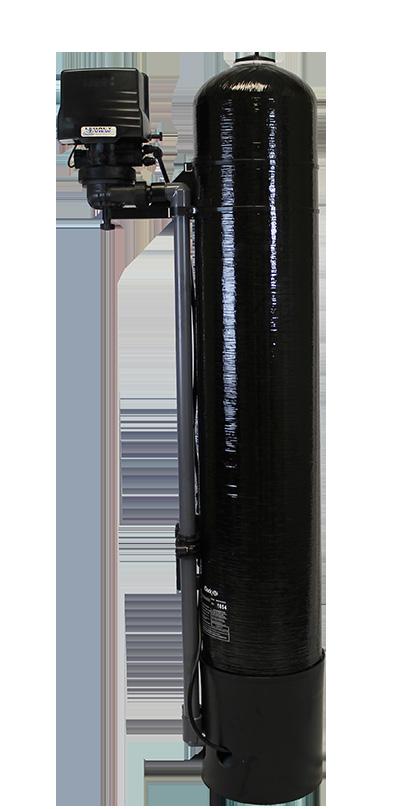
Single Tank Aeration Filter
 360 Series Single Tank Aeration Filter Installation / Operation 2017 Manual General Specifications... Page 3 Installation Requirements... Page 4 Utilizing Bluetooth... Page 8 Control Start-Up Procedures...
SIGNATURE 2 SERIES. Signature 2 Series Nitro Filter. Installation / Operation Manual
 Signature 2 Series Nitro Filter Installation / Operation Manual General Specifications...Page 2 Installation Requirements...Page 3 Electrical Connection...Page 5 Final Check & Annual Maintenance...Page
SIGNATURE 2 SERIES. Reactr VS Filter Manual. Installation / Operation Manual
 Reactr VS Filter Manual Installation / Operation Manual Filter Specifications...Page 3 Installation...Page 4 Control Start-Up Procedures...Page 8 Utilizing Bluetooth...Page 11 Master Programming...Page
Cabinet Softener Manual. Installation / Operation Manual. CABINET Water Softener
 Cabinet Softener Manual Installation / Operation Manual CABINET Water Softener Softener Specifications... Page 3 Softener Installation... Page 5 Start Up Procedure... Page 11 Master Programming... Page
SIGNATURE 2 SERIES. Signature 2 Series Hydroxr. Installation / Operation Manual
 Signature 2 Series Hydroxr Installation / Operation Manual Hydroxr Specifications...Page 3 Installation...Page 4 Control Start-Up Procedures...Page 9 Utilizing Bluetooth...Page 11 Master Programming...Page
300 SERIES. 300 Series Softener Manual. Installation / Operation Manual
 300 Series Softener Manual Installation / Operation Manual 2 Softener Specifications... Page 4 Softener Installation... Page 6 Programming the Control Valve... Page 11 Control Start-Up Procedures... Page
Cabinet Softener Manual. Installation / Operation Manual. CABINET Water Softener
 Cabinet Softener Manual Installation / Operation Manual CABINET Water Softener Softener Specifications... Page 3 Softener Installation... Page 5 Start Up Procedure... Page 11 Master Programming... Page
City Softener Manual
 SIGNATURE 2 SERIES Signature 2 Signature 3 City Softener Manual Installation / Operation Manual Softener Specifications... Page 3 Softener Installation... Page 5 Programming the Control Valve... Page 11
Cabinet Softener Manual. Installation / Operation Manual. CABINET Water Softener
 Cabinet Softener Manual Installation / Operation Manual CABINET Water Softener Softener Specifications... Page 3 Softener Installation... Page 5 Start Up Procedure... Page 11 Master Programming... Page
Cabinet Softener Manual. Installation / Operation Manual. CABINET Water Softener
 Cabinet Softener Manual Installation / Operation Manual CABINET Water Softener Softener Specifications... Page 3 Softener Installation... Page 5 Start Up Procedure... Page 11 Master Programming... Page
Cabinet Softener Manual. Installation / Operation Manual. CABINET Water Softener
 Cabinet Softener Manual Installation / Operation Manual CABINET Water Softener Softener Specifications... Page 3 Softener Installation... Page 5 Start Up Procedure... Page 11 Master Programming... Page
Tannin / Hardness Manual Installation / Operation Manual
 Signature 2 Signature 3 Tannin / Hardness Manual Installation / Operation Manual Softener Specifications... Page 3 Softener Installation... Page 5 Programming the Control Valve... Page 12 Master Programming...
Tannin / Hardness Manual Installation / Operation Manual
 Signature 2 Signature 3 Tannin / Hardness Manual Installation / Operation Manual Softener Specifications... Page 3 Softener Installation... Page 5 Programming the Control Valve... Page 12 Master Programming...
Cabinet Softener Manual. Installation / Operation Manual. CABINET Water Softener
 Cabinet Softener Manual Installation / Operation Manual CABINET Water Softener Softener Specifications... Page 3 Softener Installation... Page 5 Start Up Procedure... Page 11 Master Programming... Page
Demand Tannin / Hardness Softener Manual
 Demand Tannin / Hardness Softener Manual Installation / Operation Manual Water Softeners Softener Specifications...Page 3 Softener Installation...Page 5 Control Start Up Procedures...Page 10 Error Codes...Page
300 SERIES. 300 Series Softener Manual. Installation / Operation Manual
 300 Series Softener Manual Installation / Operation Manual 2 Softener Specifications... Page 4 Softener Installation... Page 6 Programming the Control Valve... Page 11 Control Start-Up Procedures... Page
Arsenic / Heavy Metals Filter Manual
 Arsenic / Heavy Metals Filter Manual Installation / Operation Manual Filter Specifications...Page 3 Project Data Form...Page 4 Media Disposal Considerations...Page 5 Installation...Page 6 Control Start-Up
RS1. RS1 Softener Manual. Installation / Operation Manual. CABINET Water Softener
 RS1 Softener Manual Installation / Operation Manual CABINET Water Softener Softener Specifications...Page 3 Softener Installation...Page 5 Start Up Procedure...Page 11 Master Programming...Page 13 Utilizing
SIGNATURE 2 SERIES. Signature 2 Series Metered Softener Manual. Installation / Operation Manual
 Signature 2 Series Metered Softener Manual Installation / Operation Manual Softener Specifications...Page 3 Softener Installation...Page 5 Installing the Control Valve...Page 10 Control Start-Up Procedures...Page
Isobar II Metered Softener Manual
 Isobar II Metered Softener Manual Installation / Operation Manual Softener Specifications...Page 3 Softener Installation...Page 5 Installing the Control Valve...Page 10 Control Start-Up Procedures...Page
SIGNATURE SERIES. Signature Series Duplex Softener Manual. Installation / Operation Manual
 Signature Series Duplex Softener Manual Installation / Operation Manual 1 Softener Specifications... Page 3 Softener Installation... Page 5 Service Information... Page 8 Troubleshooting... Page 13 Warranty...
Signature 2 Series Softener Manual
 Signature 2 Series Softener Manual Installation / Operation Manual Fully Automatic & Demand Water Softeners Softener Specifications...Page 3 Softener Installation...Page 5 Softener Capacity...Page 10 Installing
High Capacity Softener Manual. Installation / Operation Manual. Fully Automatic & Demand Water Softeners
 High Capacity Softener Manual Installation / Operation Manual Fully Automatic & Demand Water Softeners Softener Specifications...Page 3 Softener Installation...Page 5 Softener Capacity...Page 10 Installing
Isobar II Tannin / Hardness Manual. Installation / Operation Manual. Fully Automatic & Demand Water Softeners
 Isobar II Tannin / Hardness Manual Installation / Operation Manual Fully Automatic & Demand Water Softeners Softener Specifications...Page 3 Softener Installation...Page 5 Softener Capacity...Page 10 Installing
Birm 5900-BT Installation & Maintenance Guide
 Clean Water Made Easy www.cleanwaterstore.com Birm 5900-BT Installation & Maintenance Guide Thank you for purchasing a Clean Water System! With proper installation and a little routine maintenance your
Signature 2 Series Softener Manual
 Signature 2 Series Softener Manual Installation / Operation Manual Fully Automatic & Demand Water Softeners Softener Specifications...Page 3 Softener Installation...Page 5 Softener Capacity...Page 10 Installing
Signature 2 Series Tannin / Hardness Manual
 Signature 2 Series Tannin / Hardness Manual Installation / Operation Manual Fully Automatic & Demand Water Softeners Softener Specifications...Page 3 Softener Installation...Page 5 Softener Capacity...Page
Signature 2 Series Optimizr Manual
 Signature 2 Series Optimizr Manual Installation / Operation Manual Fully Automatic & Demand Water Softeners Softener Specifications...Page 3 Softener Installation...Page 5 Softener Capacity...Page 10 Installing
5900-BT Carbon Backwash Filter Installation & Maintenance Guide
 Clean Water Made Easy www.cleanwaterstore.com 5900-BT Carbon Backwash Filter Installation & Maintenance Guide Thank you for purchasing a Clean Water System! With proper installation and a little routine
5900-BT Softener Installation & Start-Up Guide
 Clean Water Made Easy www.cleanwaterstore.com 5900-BT Softener Installation & Start-Up Guide Thank you for purchasing a Clean Water System! With proper installation and a little routine maintenance your
7800 Neutralizer Installation & Start-Up Guide
 Clean Water Made Easy www.cleanwaterstore.com 7800 Neutralizer Installation & Start-Up Guide Thank you for purchasing a Clean Water System! With proper installation and a little routine maintenance your
5900S Arsenic Filter Operation & Maintenance Manual
 Clean Water Made Easy www.cleanwaterstore.com 5900S Arsenic Filter Operation & Maintenance Manual Thank you for purchasing a Clean Water System! With proper installation and a little routine maintenance
Clean Water Made Easy
 Clean Water Made Easy http://www.cleanwaterstore.com Pro-OX 1650 Iron Filter Installation & Start-Up Guide Thank you for purchasing a Clean Water System! With proper installation and a little routine maintenance
Installation & Service Manual
 Installation & Service Manual Table of Contents Unpacking & Inspection... 2 Basic Guidelines... 2 Specifications... 3 Before Starting Installation Where to install the filter... 4 Tools, pipe, fittings
5700-E Sediment Filter Installation & Start-Up Guide
 Clean Water Made Easy www.cleanwaterstore.com 5700-E Sediment Filter Installation & Start-Up Guide Thank you for purchasing a Clean Water System! With proper installation and a little routine maintenance
Model NFF Iron, Manganese, Hydrogen Sulfide Reduction
 Super Filter Model NFF Iron, Manganese, Hydrogen Sulfide Reduction Operating and Maintenance Manual Page 1 of this manual contains operating conditions. 57055 9/07 Enjoy clean, stain-free laundry and dishes...
5900e Greensand Filter Installation & Start-Up Guide
 Clean Water Made Easy www.cleanwaterstore.com 5900e Greensand Filter Installation & Start-Up Guide Thank you for purchasing a Clean Water System! With proper installation and a little routine maintenance
Installation, Operation, and Maintenance Manual. Waterlogix Metered Residential Water Softener
 Installation, Operation, and Maintenance Manual Waterlogix Metered Residential Water Softener Waterlogix WLS-075 Waterlogix WLS-075C Waterlogix WLS-100 Waterlogix WLS-100C Waterlogix WLS-150 Waterlogix
Clean Water Made Easy. CWS Time Clock Softener Installation & Start Up Guide. Questions?
 Clean Water Made Easy www.cleanwaterstore.com CWS Time Clock Softener Installation & Start Up Guide Thank you for purchasing a Clean Water System! With proper installation and a little routine maintenance
CWS Plus Sediment Filter Installation & Start Up Guide
 Clean Water Made Easy www.cleanwaterstore.com CWS Plus Sediment Filter Installation & Start Up Guide Thank you for purchasing a Clean Water System! With proper installation and a little routine maintenance
5900e Neutralizer Installation & Start Up Guide
 Clean Water Made Easy www.cleanwaterstore.com 5900e Neutralizer Installation & Start Up Guide Thank you for purchasing a Clean Water System! With proper installation and a little routine maintenance your
5900S Softener Installation & Start-Up Guide
 Clean Water Made Easy www.cleanwaterstore.com 5900S Softener Installation & Start-Up Guide Thank you for purchasing a Clean Water System! With proper installation and a little routine maintenance your
TITAN VI High Efficiency Water Conditioner Installation and Operation Manual
 TITAN VI High Efficiency Water Conditioner Installation and Operation Manual Manufacturer s Warranty Holts Water Conditioning 369 South Mountainway Drive Orem, UT 84058 801-426-9243 To the original purchaser,
5900S Neutralizer Operation & Maintenance Manual
 Clean Water Made Easy www.cleanwaterstore.com 5900S Neutralizer Operation & Maintenance Manual Thank you for purchasing a Clean Water System! With proper installation and a little routine maintenance your
Green Water Systems OWNERS MANUAL. Includes: Installation Procedures, Warranties, Service & Operation Guidelines.
 Green Water Systems OWNERS MANUAL Includes: Installation Procedures, Warranties, Service & Operation Guidelines. GS Elite GS PRO GS1 1 Cu. Ft. S. C. S. GS1.5 1 Cu. Ft. S. C. S. GS2 2 Cu. Ft. S. C. S. 7000
Clean Water Made Easy
 Clean Water Made Easy http://www.cleanwaterstore.com Pro-OX 2510 Iron Filter Installation & Start- Up Guide Thank you for purchasing a Clean Water System! With proper installation and a little routine
Fleck 2510 SXT Catalox Installation & Start Up Guide
 Fleck 2510 SXT Catalox Installation & Start Up Guide For Catalox Filters with PotPerm Bleach Solution Tank Thank you for purchasing a Clean Water System! With proper installation and a little routine maintenance
TITAN Pro-Max High Efficiency Upflow Water Conditioner Installation and Operation Manual
 TITAN Pro-Max High Efficiency Upflow Water Conditioner Installation and Operation Manual TITAN VI Pro-Max Manufacturer s Warranty Holts Water Conditioning 369 South Mountainway Drive Orem, UT 84058 801-426-9243
Clean Water Made Easy
 Clean Water Made Easy www.cleanwaterstore.com CWS Plus Neutralizer/Birm Blend Installation & Start-Up Guide Thank you for purchasing a Clean Water System! With proper installation and a little routine
Clean Water Made Easy. Fleck 7000 Tannin Filter Installation & Startup Guide. Questions?
 Clean Water Made Easy www.cleanwaterstore.com Fleck 7000 Tannin Filter Installation & Startup Guide For Tannin Filters with Vortech Distributor Screen Thank you for purchasing a Clean Water System! With
Fleck 5600 Carbon Filter Installation & Start Up Guide
 Clean Water Made Easy www.cleanwaterstore.com Fleck 5600 Carbon Filter Installation & Start Up Guide Thank you for purchasing a Clean Water System! With proper installation and a little routine maintenance
Fleck 7000 Sediment Filter Installation & Start-Up Guide
 Clean Water Made Easy www.cleanwaterstore.com Fleck 7000 Sediment Filter Installation & Start-Up Guide Thank you for purchasing a Clean Water System! With proper installation and a little routine maintenance
MP-MBA-45T-1/60T-1 / 75T-1
 MASTER Water Conditioning Corp. www.masterwater.com Installation and Operation Manual MP-MBA-45T-1/60T-1 / 75T-1 with the 268/762 Logix Control Valve July 2006 Table of Contents Page No. Topic Description
Pro-Ox 5900S Installation & Start-Up Guide
 Clean Water Made Easy www.cleanwaterstore.com Pro-Ox 5900S Installation & Start-Up Guide Thank you for purchasing a Clean Water System! With proper installation and a little routine maintenance your system
MASTER. Water Conditioning Corp. MP-TS-10T/20T with the 255/762 Logix Control Valve With Vortech. Installation and Operation Manual
 MASTER Water Conditioning Corp. www.masterwater.com Installation and Operation Manual MP-TS-10T/20T with the 255/762 Logix Control Valve With Vortech February 2010 Table of Contents Page No. Topic Description
6700 Valve Upflow. Automatic Water Softeners Operation Manual. Read all instructions carefully before operation. #57341 Rev.
 6700 Valve Upflow Automatic Water Softeners Operation Manual Read all instructions carefully before operation. #57341 Rev. 11/08 US Performance and Specifications Upflow Capacity at Various Salt Dosages
AUTOTROL 363TC AUTOMATIC FILTER VALVE SERVICE MANUAL
 AUTOTROL 363TC AUTOMATIC FILTER VALVE SERVICE MANUAL 2013 Pentair Residential Filtration, LLC www.pentairaqua.com/pro TABLE OF CONTENTS MANUAL OVERVIEW... 2 SAFETY INFORMATION... 2 TYPICAL TOOLS AND FITTINGS
7500-S Sediment Backwash Filter Guide
 Clean Water Made Easy. www.cleanwaterstore.com 7500-S Sediment Backwash Filter Guide Thank you for purchasing a Clean Water System! With proper installation and a little routine maintenance your system
Pro-Ox 5900S-AIR Installation & Start-Up Guide
 omniscient Clean Water Made Easy www.cleanwaterstore.com Pro-Ox 5900S-AIR Installation & Start-Up Guide Thank you for purchasing a Clean Water System! With proper installation and a little routine maintenance
Fully Automatic Water Filters
 INSTALLATION INSTRUCTIONS Fully Automatic Water Filters INSTALLATION INFORMATION Model No. Unit Date Code Date Installed WATER ANALYSIS RECORD Hardness GPG Sulfur PPM Iron PPM ph Manganese PPM Tannins
Econoflo SXT Automatic Meter Initiated Water Softener
 Econoflo SXT Automatic Meter Initiated Water Softener Operating and Maintenance Manual Page 5 of this manual contains important maintenance procedures for the continued proper operation of your unit. These
The Inlet and Outlet should be as per below illustration. This will ensure that water will flow through the filter in an upflow configuration
 Owners Manual The Inlet and Outlet should be as per below illustration. This will ensure that water will flow through the filter in an upflow configuration INLET OUTLET NRV Filter FOLLOWTHE INSTALLATION
6700 Valve Downflow. Automatic Water Softeners Operation Manual. Read all instructions carefully before operation. #51431 Rev.
 6700 Valve Downflow Automatic Water Softeners Operation Manual Read all instructions carefully before operation. #51431 Rev. 11/08 US Performance and Specifications Downflow Capacity at Various Salt Dosages
7000 Meter Initiated Valve
 7000 Meter Initiated Valve Water Softener Operation Manual Read all instructions carefully before operation. #51400 Rev. 2/09 Performance and Specifications Item Model Capacity at regeneration salt levels
Installation Manual & Owner s Guide
 Installation Manual & Owner s Guide Table of Contents Benefits of Iron Shield +... 1 How Iron Shield + Works... 2 Unpacking & Inspection... 3 Basic Guidelines... 3 Specifications... 4 Regeneration Schedules...
Autotrol Performa FA Valve
 Autotrol Performa FA Valve With 400 Series Control Water Conditioning Control System Dealer Installation, Operation, and Maintenance Manual Table of Contents Installation................................
GRANT-DILLING-HARRIS INC. WATER SOFTENER THEORY OF OPERATION
 GRANT-DILLING-HARRIS INC. WATER SOFTENER THEORY OF OPERATION WATER SOFTENER: The Water Softener requires a 120VAC 2 AMP electrical service and the Water lines in and out need to be sized to the Softener.
Fully Automatic Water Softeners
 OWNERS GUIDE TO INSTALLATION AND OPERATION Fully Automatic Water Softeners SINGLE TANK CABINET MODELS TWO TANK MODELS Read the instructions carefully and learn the specific details regarding installation
SYSTEMS for CATALYTIC FILTERS
 OP40U5F, OP40B5F, OP80U10F, OP80B10F, OP120U15F & OP120B15F INSTALLATION, OPERATION & SERVICE INSTRUCTIONS Hydrogen Sulfide Removal SYSTEMS for CATALYTIC FILTERS NO DIAPHRAGMS OR AIR CELLS COMPLETELY CORROSION
Clean Water Made Easy
 Clean Water Made Easy http://www.cleanwaterstore.com Pro-OX 5700-E Iron Filter Installation & Start-Up Guide Thank you for purchasing a Clean Water System! With proper installation and a little routine
Fleck 2510 Sediment Filter Installation & Start-Up Guide
 Clean Water Made Easy www.cleanwaterstore.com Fleck 2510 Sediment Filter Installation & Start-Up Guide Thank you for purchasing a Clean Water System! With proper installation and a little routine maintenance
Pro-Ox 5900S-AIR Installation & Start-Up Guide
 Clean Water Made Easy www.cleanwaterstore.com Pro-Ox 5900S-AIR Installation & Start-Up Guide Thank you for purchasing a Clean Water System! With proper installation and a little routine maintenance your
Installation Instructions & Operating Manual. EM Series. Water Softener System
 Installation Instructions & Operating Manual EM Series Water Softener System First Sales, LLC 1630 US Highway 33 N Churubusco, IN 4673 Phone (60) 693-197 Fax (60) 693-060 EM Installation Manual 170818.docx
IMPORTANT SAFETY INFORMATION READ ALL...
 INSTALLATION and SERVICE MANUAL HOUSEPURE MODELS HP03 and HP04 736-0137 Table of Contents IMPORTANT SAFETY INFORMATION READ ALL... 3 P/N 41482 Rev A 06/04 INSTRUCTIONS BEFORE USING... 3 FEEDWATER... 4
WS1 Greensand Installation & Start Up Guide
 WS1 Greensand Installation & Start Up Guide Thank you for purchasing a WS1 Water System for the removal of iron, manganese and hydrogen sulphide gas. With proper installation and a little routine maintenance
ProFlo SXT Valve Downflow / Upflow
 ProFlo SXT Valve Downflow / Upflow Automatic Water Softeners Operation Manual Read all instructions carefully before operation. #54719 Rev. 1/09 US Performance and Specifications Downflow Upflow Capacity
ispring Whole House Water Filter Systems USER S MANUAL
 ispring Whole House Water Filter Systems USER S MANUAL Version 2014-5 Introduction Congratulations on your purchase of the ispring Whole House Water Filter system. Featuring a three-stage filtration process,
6700XTR Valve Downflow
 6700XTR Valve Downflow Automatic Water Softeners Operation Manual Read all instructions carefully before operation. #51545 Rev. 11/08 US Performance and Specifications Downflow Capacity at Various Salt
Owner's Manual. Whole House Water Softener with Triton Electronic Control Valve. or call
 Owner's Manual SoftMAX Whole House Water Softener with Triton Electronic Control Valve ACTIVATE YOUR WARRANTY BY REGISITERING YOUR PRODUCT AT WWW.WATERTECH.COM or call 888-254-8412 Dealer Contact and Product
FULLY AUTOMATIC WATER SOFTENER
 OWNERS GUIDE TO INSTALLATION AND OPERATION Section: 6.10.130 FM2035 0302 Supersedes 0102 FULLY AUTOMATIC WATER SOFTENER MODEL 340 SAFETY INFORMATION Read the instructions carefully and learn the specific
Water Softener Installation Guide Effective for all Softeners from our Range
 Water Softener Installation Guide Effective for all Softeners from our Range Planning Your Installation Always observe the water byelaws. Ensure there is only one rising main, that you have allowed space
Owner's Manual. WS Series. Water Softener
 Owner's Manual WS-165-150 Series Water Softener Table of Contents WHAT'S INCLUDED 3 OPERATING CONDITIONS 4 ASSEMBLY INSTRUCTIONS 6 FLUSHING THE WATER LINES 13 MASTERPROGRAMMING 14 PROGRAMMING KEYAND GENERAL
INSTALLATION MANUAL ESM9+ / ESM11+ / ESM15+
 INSTALLATION MANUAL ESM9+ / ESM+ / ESM5+ THANK YOU Thank you for choosing a water softener from EcoWater. With over 80 years experience we have manufactured your new water softener from quality corrosion
Installation, Operation and Maintenance Manual. Infusion Residential Water Softener 169-ISF-1C 169-ISF-2C 169-ISF-3C 169-ISF-4C
 Installation, Operation and Maintenance Manual Infusion Residential Water Softener Calcium, magnesium removal system 169-ISF-1C 169-ISF-2C 169-ISF-3C 169-ISF-4C US Water Systems, Inc. 1209 Country Club
This material is intended only for Glass Water Systems customers. Reproduction or distribution of this material is strictly prohibited and protected.
 This material is intended only for Glass Water Systems customers. Reproduction or distribution of this material is strictly prohibited and protected. For further questions contact Glass Water Systems or
Fleck 2510 Softener Installation & Start Up Guide
 Clean Water Made Easy www.cleanwaterstore.com Fleck 2510 Softener Installation & Start Up Guide Thank you for purchasing a Clean Water System! With proper installation and a little routine maintenance
1850 Series TRIPLE TREAT Operation Manual
 1850 Series TRIPLE TREAT Operation Manual BRINE TANK RESIN TANK CARBON TANK System shown with optional tank jackets. Note: 1. Read all instructions carefully before operation. 2. Avoid pinched o-rings
Water Softener & Single Tank Triple Treat System Installation Overview. Using 1850 Metered Valves
 Water Softener & Single Tank Triple Treat System Installation Overview Using 1850 Metered Valves System Installation CAUTION: Do not use systems on untreated well water that is microbiologically unsafe.
541D19 SERIES. Technical Manual. A Division of Aquion Partners L.P.
 541D19 SERIES Technical Manual A Division of Aquion Partners L.P. Table of Contents Introduction... Page 1 Technical Specifications... Page 2 Flow Diagrams... Page 3 Injector & Flow Control Selection Injector...
High Flow 7000 SXT Series Water Softeners
 High Flow 7000 SXT Series Water Softeners Operating and Maintenance Manual Read all instructions carefully before operation. #54736 12/08 Performance and Specifications Model Capacity - Grains Flow Rates
Installation Instructions and Owner s Manual. HE, IM & INT Series. Water Softener System
 Installation Instructions and Owner s Manual HE, IM & INT Series Water Softener System First Sales, LLC 1630 US Highway 33 N Churubusco, IN 4673 Phone (60) 693-197 Fax (60) 693-060 HE-IM-INT Instruction
6700XTR Upflow Valve. Water Softener Operation Manual. Read all instructions carefully before operation. #51548 Rev. 2/09
 6700XTR Upflow Valve Water Softener Operation Manual Read all instructions carefully before operation. #51548 Rev. 2/09 Performance and Specifications Item Model Capacity at regeneration salt levels Service
Metermatic Water Softener. Operation Manual
 Metermatic Water Softener Operation Manual Page 5 of this manual contains important maintenance procedures for the continued proper operation of your unit. These MUST be performed regularly for your guarantee
OWNER S MANUAL. Premium Series Two Tank 1-PLUS-1 Water Conditioner & Whole House Filters
 OWNER S MANUAL Premium Series Two Tank 1-PLUS-1 Water Conditioner & Whole House Filters Congratulations! You ve selected our Premium Series Two Tank 1-PLUS-1 water conditioner and whole house filter for
Installation Instructions & Owner's Manual. IM & INT Series
 Installation Instructions & Owner's Manual IM & INT Series 12630 US Highway 33 N. Churubusco, IN 46723 Phone: (260) 693-1972 Fax: (260)693-0602 www.sterlingwatertreatment.com TABLE OF CONTENTS: Preinstallation
DEHUMIDIFIER. User Manual 50BT, 70BT
 User Manual DEHUMIDIFIER Model 50BT, 70BT Use & Care Guide Please read and follow all safety rules and instructions in this manual before operating. The product warranty is printed on the back of this
programmable control model installation and setup guide M /11/ Hunter Fan Company
 programmable control model 99107 installation and setup guide installation Prior to installation, download the app to ensure phone compatibility: Visit your app store and search simpleconnect to find the
Plumbline 2000 Series Metered Softeners Owners Manual Water Softener Models
 Plumbline 2000 Series Metered Softeners Owners Manual Water Softener Models PS2000M PS2500M PS2700M PS2900M Table of Contents How to Use Soft Water 3 Product Line Overview 5 System Operation 6 System Maintenance
High Flow 7000 SXT Water Softener
 High Flow 7000 SXT Water Softener Operating and Maintenance Manual WQA Tested and Certified against CSA B483.1 Read all instructions carefully before operation. #54736WQA 3/11 ii Performance Data Sheet
Iron Air Charge MangOx 2510 SXT Installation & Start Up Guide
 Iron Air Charge MangOx 2510 SXT Installation & Start Up Guide Thank you for purchasing a Clean Water System! With proper installation and a little routine maintenance your system will be providing iron