Ducted Split Wine Cellar Cooling Systems
|
|
|
- Ambrose Short
- 5 years ago
- Views:
Transcription


1 Ducted Split Wine Cellar Cooling Systems Installation, Operation and Maintenance Guide Model DS025, DS050, DS088 (60Hz) Model WGS40, WGS75, WGS100 (50Hz) Manufactured by: Wine Guardian reserves the right, without notice, to make changes to this document at its sole discretion. Please visit our web site for the most current version of the Wine Guardian manual and other literature. Wine Guardian is a registered trademark (2,972,262) of Air Innovations, Inc. Condensing Unit Patent No. U.S. D791295, EU Edition Air Innovations, 2018 Part No. 15H
2 Table of Contents Directory of Terms... 6 Receiving, Inspecting and Unpacking the Wine Guardian Unit... 8 Review the Packing Slip to Verify:... 8 Check the fan coil unit for... 8 Check the condensing unit for:... 8 General Description... 9 The Wine Guardian Ducted Split System Contains... 9 Wine Guardian Fan Coil Unit Electrical Controls Condensing Unit Accessories and Optional Equipment Condensate Pump (Part # 94H ) Duct Collars and Flexible Ducts Extended Compressor Warranty Heating Coils Humidifier Xtreme Low Ambient (see illustrations on following page) Xtreme Low Ambient Illustrations Overview of the Wine Guardian fan coil Wine Guardian dimension for ducted systems DS025, WGS40 and DS050, WGS Condensing unit dimensions Wine Guardian dimensional drawing for models DS025 and WGS Refrigeration Illustration of the system Magnified Image of the Condensing Unit Wiring Diagram for DS025 & DS Wiring Diagram for DS088 and WGS100 Units Wiring Diagram for WGS40 & WGS Wiring Diagram for DS025 and WGS40 Condensing Unit Wiring Diagram for DS050 and WGS75 Condensing Unit Wiring Diagram for DS088 and WGS100 Condensing Unit Ducted Split Systems Specifications - 60Hz Models DS025, DS050, DS Ducted Split System Specifications 50 Hz Models WGS40, WGS75, WGS Safety Safety Message Conventions Danger Warning Caution Lockout/Tagout Procedure Safety Considerations... 27
3 Safety Hazards Electrical Hazards Electrical Shock Hazards Hot Parts Hazards Moving Parts Hazards Equipment Safety Interlocks Main Power Switch Installation Pre-installation Test Air Flow Diagram Planning the Installation Addressing Items in the Planning Process Performing a Pre-Installation Check Installing the Fan Coil Unit Floor Mounting Wall Mounting Ceiling Mounting Typical Mounting Arrangements Handling and Installation Floor Mount Wall Mount Installing the Ductwork and Grilles Duct Collars Location of Supply and Return Grilles General Duct Recommendations Reducing Noise from the Unit Installing the Condensate Drain Connection Installing the Drain Line Priming the Drain Trap Wiring the Fan Coil Unit for Power Installing the Condensing Unit Installation of Interconnecting Refrigerant Lines (Suction and Liquid) Split System Interconnecting Line Sizing Chart Sample Piping Configurations Leak Checking and Evacuation Process Wiring Refrigerant Charging Determining the amount of charge Procedures for Charging System with Head Pressure Control Superheat... 48
4 Sub-Cooling Split System Operations Chart Installing the Remote interface controller and Communication Cable Mounting the Remote Interface Controller Installing the Wine Guardian Remote Sensor Mounting the Remote Sensor Joining the Communication Cable Changing Jumper Positions Standard Controller Functions Alarm Codes Inspection and Start Up Checklists Receiving and Inspecting Handling and Installing Starting-up the Unit Starting-up and Operating the Wine Guardian Split System Turn on the Unit Testing the Fan Running the Unit Cycling the Unit Setting the Remote Interface Controller Regulating the Wine Cellar Temperature Changing the Air Flow Direction Maintenance General Cleaning the Condensate Drain System Cleaning the Humidifier Heating Coil Option Maintenance Schedule Monthly Yearly Troubleshooting Typical start up problems Unit does not start up Unit is operating and blows evaporator air but the supply air is not colder than the return air from the cellar Humidity Issues Too low, without optional humidifier Humidity too low, with optional humidifier Humidity too high when unit is running but not cooling Humidity too high when unit is not running... 69
5 Humidity too high when unit is running and cooling Unit operates but the power switch light is not ON Unit is leaking water Unit is running properly, but the sound of the unit objectionable High Pressure Switch has Shut the Unit Down Instructions to Reset High Pressure Switch Advanced Troubleshooting Evaporator Coil is Freezing Unit cycles on and off more than 8 times/hr Replacing the blowers Contact and Warranty Information Warranty... 73
6 Directory of Terms Ambient Air The surrounding area outside the wine cellar such as a room, basement, garage or outdoors. BTU/H British thermal units/hour. A unit of measurement to describe the power of heating and cooling system. CFM Cubic feet per minute. A unit of measurement for the amount of air handled by the fan. Condensate / Condensation The water formed out of the air when it is cooled below a certain temperature (called dew point). Often referred to as sweating on pipes and cold surfaces. This water collects at the bottom of the evaporator or cooling coil and drains out of the unit through the drain line. Condensing Unit (Heat Rejection) The condensing unit uses the compressor, condenser coil and fan to remove heat from the refrigerant to the ambient air outside the wine cellar. The word condenser refers to the condensation of the refrigerant from gas to liquid phase. CSA/ETL Canadian Standards Association/Edison Testing Laboratory (product compliance to safety standards) F (Degrees) Fahrenheit Fan Coil Unit (Evaporator Cooling) The fan coil unit uses the cooling coil and the fan to remove heat from the air inside the wine cellar to the refrigerant, cooling the air and condensing moisture out of the air. The word evaporator refers to the evaporation of the refrigerant from liquid to gas phase in the coil. The fan coil unit is ducted to or can be placed inside the wine cellar. Flexible Duct Round ducts with steel reinforced plastic liners, a layer of insulation and an outer plastic layer used to convey the air from the unit to the wine cellar or ambient space. Grille or Diffuser Inlet or outlet plates to direct the airflow or protect the inside of the unit. Heat Gain / Loss The amount of cooling or heating expressed in watts transferred between the wine cellar and the ambient space. The Wine Guardian must offset this heat/gain loss. Inlet Air The air returning from the wine room to the Wine Guardian fan coil. I.D. Inside diameter NEC National Electrical Code O.D. Outside diameter Psig Pounds Force per square inch gauge Recovery The amount of cooling the unit does to return the cellar to its set point temperature after some new heat load is introduced, such as people or new cases of warm wine entering the cellar. Return Air - The air leaving the cellar and returning to the inlet of the fan coil. (See Inlet Air above) 6
7 TXV Thermal expansion valve VAC Volts alternating current SP Static pressure. Unit of measurement (inches of water column) of the pressure of the air handled by the fan. Set Point The desired temperature or humidity set on the remote interface controller or humidistat. Supply Air - The air entering the wine cellar from the discharge of the fan coil. 7
8 Receiving, Inspecting and Unpacking the Wine Guardian Unit IMPORTANT This appliance is not intended for use by persons (including children) with reduced physical, sensory or mental capabilities, or lack of experience and knowledge, unless they have been given supervision or instruction concerning use of the appliance by a person responsible for their safety. Children should be supervised to ensure that they do not play with the appliance. NOTE: Wine Guardian units are factory assembled and tested prior to shipment. The Wine Guardian Ducted Split System consists of two separate components, the Wine Guardian fan coil and condensing unit. Each Wine Guardian component is shipped in a corrugated box. A shipment may include one or more boxes containing accessories. Lift at the designated handhold locations only or fully support from underneath. Before opening, inspect the packing crates or boxes for obvious signs of damage or mishandling. Write any discrepancy or visual damage on the bill of lading before signing. Inspect all equipment for any sign of damage caused during transit. Report all visual or concealed damage to the carrier and file a claim immediately. Thoroughly inspect the contents for any visible damage or loose parts. IMPORTANT If this procedure is not followed, the shipping company may reject the claim and the consignee may suffer the loss. Do not return the shipment to the factory. Review the Packing Slip to Verify: 8 Model number Factory installed options Unit accessories If any items listed on the packing slip do not match your order information, contact the place of purchase immediately. Check the fan coil unit for: An electrical power cord A remote interface controller with communications cable plugged into side of unit A drain line coming out of the unit One supply duct collar and one return duct collar Check the condensing unit for: Weather proof enclosure, top and sides
9 General Description IMPORTANT Design and specifications are subject to change without notice The Wine Guardian cooling unit is a professional grade, American-manufactured, split two-piece climate control unit designed specifically for the storage of wine at cellar temperatures. It is designed for easy installation and operation. Wine Guardian uses digital electronic controls and R-134a refrigerant. The entire Wine Guardian fan coil section and the condensing unit is tested at the factory. All components are of a high quality standard commercial grade. The entire system is approved by ETL according to UL 1995 and CSA safety standards. All wiring complies with NEC. Each Wine Guardian fan coil section is furnished with a sealed, UL-approved power cord and plug. All Wine Guardian 50Hz units carry the CE mark. Each unit is furnished with a sealed, CE- approved power cord. The Wine Guardian Ducted Split System Contains 9 1. A Wine Guardian Fan Coil Unit with: A thermal expansion valve to control the flow of refrigerant into the evaporator coil A built-in condensate drain trap. No external trap is required. A removable control panel for ease of service Supply duct collar Return duct collar Remote interface controller and control cable 2. A Condensing Unit with: A filter dryer to keep the refrigerant clean and free of contaminants A sight glass to observe the level of refrigerant A manual reset high pressure switch on the discharge to protect the compressor from high pressures. Auto reset low pressure switch 24-volt contactor for control of fan coil unit Outdoor enclosure Crankcase heater Low ambient refrigeration controls (see page 11 for Xtreme Low Ambient option)
10 Wine Guardian Fan Coil Unit The Wine Guardian fan coil unit meets its rated capacities for total BTU/H and CFM (watts and M 3 /h for 50Hz) at design cellar conditions and external static pressures. The fan coil unit is capable of rated CFM (M 3 /h for 50Hz) against the static pressure imposed by recommended ductwork. The fan is a motorized impeller type, statically and dynamically balanced, and uses permanently lubricated direct drive motors requiring no maintenance. The Wine Guardian fan coil section operates as air passes through the cooling coil and is cooled by the refrigerant inside the coil. This causes any excess humidity in the air to condense and be captured in the drain pan and piped outside the unit. Air then enters the fan where it is pressurized and discharged out of the unit through one of five openings. Optional heating coils are located between the cooling coil and the fan. These coils heat the air to prevent low temperatures in the cellar. All exterior framing of the Wine Guardian is powder coated inch gauge aluminum to prevent rust and corrosion. All coils are aluminum tubes, aluminum fins to protect against premature corrosion. The unit uses an external drain to remove excess moisture and not reintroduce it into the cellar or ambient space. Removable, multiple access doors are provided to facilitate cleaning and maintenance, duct connections, and access to components and wiring. The fan coil has at least five discharge outlets to facilitate custom installations. Each unit is provided with a pre-wired and tested remote interface controller for remote mounting within the wine cellar. The remote interface controller has multiple control functions for cooling, heating and operation. It has a fully automatic mode to switch between heating and cooling. Electrical Controls The main electrical control board and components are located on a separate panel accessible through a side door panel or by removal of the on/off panel from the system chassis. All wiring is in accordance with the NEC. Wires are numbered and color coded to match the wiring diagrams. Electric power is supplied by a single factory-furnished cord and plug. All external controls are digital and proprietary to Wine Guardian products. Only approved communication cable and Wine Guardian controllers are suitable for proper system operation. Condensing Unit Compressors are self-lubricating, permanently sealed, hermetic reciprocating-type compressors, with internal overload protection and capacitor start. The condensing unit includes a five-year warranty. Compressors are mounted on rubber-in-shear isolators to reduce noise and vibration. Additional features include a liquid line filter drier, Sporlan Head Master Controls, a liquid line receiver and refrigerant sight glass. Each unit is housed in a painted aluminum enclosure suitable for outdoor installation. The outdoor enclosure has adequate area for ventilation and refrigerant piping penetrations. All units come factory-configured with low-ambient protection for exposure to cold weather. This feature controls the system pressures to prevent evaporator coil freezing (based on head pressure) and heats the compressor coil reservoir. 10
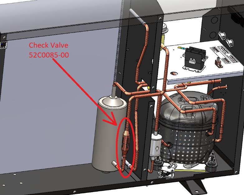
11 IMPORTANT The air exhaust from the condensing unit is hot and will be 25 to 35 degrees F or 15 C to 20 C above the entering temperature. The condensing units are rated for a maximum temperature of 115 degrees F(46 C). The condensing units should be installed in a well-ventilated area to ensure proper air flow across the condenser coil and to limit short cycling. Accessories and Optional Equipment Condensate Pump (Part # 94H ) An optional Wine Guardian automatic condensate pump is available to pump the water to a remote sink, drain pipe or outside. It requires a separate 120-volt electrical outlet. 50Hz models require a separate 220/240-volt electrical outlet. Duct Collars and Flexible Ducts Ducting for the Wine Guardian is sold in kits by size for each unit. Each kit contains two adapter collars, one 25-foot (7.6 meters) length of round flexible duct and two straps. The number of duct kits needed depends on the wine cellar layout and application. The size of the kit depends on the model Wine Guardian selected. Follow installation instructions carefully. Poorly or incorrectly installed ducts can degrade the performance of your unit dramatically. Extended Compressor Warranty The Wine Guardian uses only the best commercially available compressors on the market. However, since the compressor is the single most expensive component in the unit, it is recommended that you purchase the extended warranty option. Heating Coils An optional heating coil is built in and requires no additional power source. The electric heating option is factory installed and includes primary and secondary over-temperature protection devices per UL and NEC. Humidifier Another popular option for the Wine Guardian is a humidifier. The humidifier is available for split system installation and can be retrofitted onto any existing Wine Guardian unit. Each humidifier is furnished with a power cable connection to plug into the side of the Wine Guardian fan coil unit. It is then controlled by the same remote interface controller that is used for the operation of the Wine Guardian unit. The humidifier mounts directly onto the Wine Guardian unit and requires a water supply and drain for operation. CAUTION CAREFULLY FOLLOW THE INSTALLATION INSTRUCTIONS INCLUDED WITH THE HUMIDIFIER. REFER TO THE INSTRUCTIONS CONTAINED IN THE BOX FOR THE HUMIDISTAT. Xtreme Low Ambient (see illustrations on following page) The Xtreme Low Ambient options consists of factory installed refrigeration controls mounted within the condensing unit for continuous operation of the Wine Cellar cooling unit down to a minimum temperature of -20 Deg F (-29 Deg C). Included in the refrigeration controls are; Check valve installed in the liquid line between the head pressure control valve and receiver Fan cycling switch Heater and insulation for the receiver Adjustable low-pressure cutout timer installed on the compressor discharge line 11

12 Xtreme Low Ambient Illustrations Fig. 1 Fig. 2 12
13 Overview of the Wine Guardian fan coil Fig. 1 C A Wine Guardian. dimension for ducted systems DS025, WGS40 and DS050, WGS75 See diagram on next page for the condensing unit Model Number DS025 -WGS40 DS050/WGS75 (50Hz) DS088/WGS100 DS200/WGS175 (60Hz) Inches / cm Inches/cm Inches/cm Inches/cm A Width 14.0/ / B Height 14.1/ / C Length 16.7/ / D Evap. Discharge (OD) 7.93/ / DI Evap. Inlet (OD) 7.94/ / E Outlet opening width 9.9/ / F - Outlet opening height 11.13/ / G Drain outlet location.656/ / AA Discharge opening 7.50/ / height BB Discharge opening 7.0/ / width CC Inlet opening height 7.06/ / DD Inlet opening width 7.0/ / EE Suction Line (OD) 0.37/ / / /1.9 FF Liquid Line (OD) 0.25/ / / /0.953 CH Condenser Height 25.12/ / / CL Condenser Length 9.0/ / / CW Condenser Width / / /
14 14 Condensing unit dimensions
15 Wine Guardian dimensional drawing for models DS025 and WGS40 DS025/DS050 Ducted Evaporator Indoor Unit 15
16 Refrigeration Illustration of the system See next page for magnified image 16
17 17 Magnified Image of the Condensing Unit
18 Wiring Diagram for DS025 & DS050 18
19 19 Wiring Diagram for DS088 and WGS100 Units
20 Wiring Diagram for WGS40 & WGS75 20
21 Wiring Diagram for DS025 and WGS40 Condensing Unit 21

22 Wiring Diagram for DS050 and WGS75 Condensing Unit 22

23 23 Wiring Diagram for DS088 and WGS100 Condensing Unit
24 Ducted Split Systems Specifications - 60Hz Models DS025, DS050, DS088 SPECIFICATIONS 24 Ducted Split System - M odel Number Performance Net Cooling * Total F (minus 12 C) condenser inlet F (4 C) condenser inlet F (15 C) condenser inlet F (21 C) condenser inlet F (27 C) condenser inlet F (32 C) condenser inlet F (46 C) condenser inlet F (50 C) condenser inlet air Controls Type Temperature Accuracy/RH% Accuracy Fan-coil Section Fan Motor Size Rated Air Flow (free blow) Rated Air Max allow pressure loss Heat (Option) Type Capacity Humidifier (Option) Type Capacity - water temp of 60 F (15 C) Capacity - water temp of 90 F (32 C) Capacity - water temp of 120 F (49 C) Electrical Requirements - Evaporator Section Power Current Draw - Cooling mode Current Draw - Heating mode Minimum Circuit Size (w/heat option) Optional Humidifier Cabinet - Evaporator Section Fan coil construction Finish Weight Length Width Height Condensate Drain Condensing Unit Nominal Compressor Fan Motor Size Rated Air Flow (free blow) Weight Enclosure - Condensing Unit Construction Finish Width Length Height Electrical Requirements - Condensing Unit Power MCA MOP Agency Approval(s) DS025 DS050 DS /3100 BTUH 5400/4100 BTUH 10500/8400 BTUH 3700/3100 BTUH 6300/4900 BTUH 10600/8600 BTUH 3400/3000 BTUH 6600/5200 BTUH 10200/8200 BTUH 3600/3000 BTUH 6500/5000 BTUH 10100/7700 BTUH 3400/3100 BTUH 6300/4900 BTUH 9600/7500 BTUH 3100/2700 BTUH 5600/4400 BTUH 9000/6900 BTUH 2900/2500 BTUH 5000/3700 BTUH 8500/6500 BTUH 2400/2400 BTUH 4700/3400 BTUH Room mounted non-programmable combination thermostat humidistat +/- 1 Deg F / +/- 10% RH 90 Rated Watts 115 Rated Watts 220 Rated Watts 230 CFM 410 CFM N/A 0.10"wc / CFM 0.20" wc / CFM 445 CFM Electic Electric Electric 1000 Watts 1000 Watts 2000 Watts Removeable drip pad with integral fan 0.42 lbs/hr 0.42 lbs/hr 0.42 lbs/hr 0.97 lbs/hr 0.97 lbs/hr 0.97 lbs/hr 1.11 lbs/hr 1.11 lbs/hr 1.11 lbs/hr 115 Volts/1 phase/60hz 115 Volts/1 phase/60hz Volts/1 phase/60hz 0.8 Amps 0.9 Amps 1.05 Amps 9.4 Amps 9.6 Amps 10.7 Amps 11.6Amps 11.8 Amps 13.1 Amps 0.3 Amps 0.3 Amps 0.3 Amps Aluminum Black - textured epoxy powder coat 25 lbs 35 lbs 37 lbs 16.7 inches 16.7 inches Inches 14.0 inches 22.0 inches inches 14.1 inches 14.1 inches Inches 0.5 inches 0.51 inches 0.51 inches DS025 Cond DS050 Cond DS088 Cond 3.1 Amps 4.8 Amps 11.3 Amps 75 Watts 75 Watts 150 watts 500 CFM 500 CFM 420 CFM 75 lbs 76 lbs 152 lbs Aluminum Aluminum Aluminum Powder-coated Powder-coated Powder-coated 9.0 inches 12.3 inches 12.3 inches 34.0 inches 34.0 inches 34.0 inches inches inches inches 208/230 Volts/1 Phase/60Hz 208/230 Volts/1 Phase/60Hz Volts/1 Phase/60Hz 4.2 Amps 6.4 Amps 14.9 Amps 8.0 Amps 10.0 Amps 25 Amps ETLc ETLc ETLc 1. Net cooling capacity at entering temperature and humidity conditions of 57 Deg F (14 Deg C) and 55% RH at rated airflow. Reduce capacity by 3% for each 10% reduction in evaporator airflow. 2. Wine Guardian reserves the right to make changes to this document w ithout prior notice at its sole discretion. 3. All ratings at sea level Performance Drive North Syracuse, New York USA Fax info@wineguardian.com Rev. 07//2018
25 Ducted Split System Specifications 50 Hz Models WGS40, WGS75, WGS100 SPECIFICATIONS Ducted Split System - 25 M odel Number Performance Net Cooling * Total F (minus 12 C) condenser inlet F (4 C) condenser inlet F (15 C) condenser inlet F (21 C) condenser inlet F (27 C) condenser inlet F (32 C) condenser inlet F (46 C) condenser inlet F (50 C) condenser inlet air Controls Type Temperature Accuracy/RH% Accuracy Fan-coil Section Fan Motor Size Rated Air Flow (free blow) Rated Air Max allow pressure loss Heat (Option) Type Capacity Humidifier (Option) Type Capacity - water temp of 60 F (15 C) Capacity - water temp of 90 F (32 C) Capacity - water temp of 120 F (49 C) WGS40 WGS75 WGS100 (50Hz) 1140/879 Watts 1600/1300 Watts 2960/2315 Watts 1140/937 Watts 1780/1460 Watts 2930/2285 Watts 1115/860 Watts 1715/1440 Watts 3077/2256 Watts 1110/850 Watts 1750/1380 Watts 2930/2168 Watts 1055/835 Watts 1550/1310 Watts 2813/2110 Watts 965/730 Watts 1360/1150 Watts 2520/1846 Watts 850/675 Watts 1300/1080 Watts 2373/1758 Watts 640/640 Watts 1200/1000 Watts 85 Rated Watts 120 Rated Watts 230 Rated Watts 390 M 3 h 680 M 3 h N/A 374 M 3 h 630 M 3 h 750 M 3 h Electric Electric Electric 1000 Watts 1000 Watts 2000 Watts Removeable drip pad with integral fan.19 kg/hr.19 kg/hr.19 kg/hr.44 kg/hr.44 kg/hr.44 kg/hr 0.5 kg/hr 0.5 kg/hr 0.5 kg/hr Electrical Requirements - Evaporator Section Power Volts/1 phase/50hz Volts/1 phase/50hz Volts/1 phase/50hz Current Draw - Cooling mode 0.4 Amps 0.5 Amps 1.0 Amps Current Draw - Heating mode 4.75 Amps 4.70 Amps 10.7 Amps Minimum Circuit Size (w/heat option) 5.84 Amps 5.75 Amps 13.1 Amps Optional Humidifier 0.3 Amps 0.3 Amps 0.3 Amps Cabinet - Evaporator Section Fan coil construction Finish Weight Length Width Height Condensate Drain Condensing Unit Nominal Compressor Fan Motor Size Rated Air Flow (free blow) Weight Enclosure - Condensing Unit Construction Finish Width Length Height Aluminum Black - textured epoxy powder coat 11.3 kg 15.5 kg 15.5 kg 42.5 cm 42.5 cm 42.5 cm 35.6 cm 55.8 cm 55.8 cm 35.8 cm 35.6 cm 35.8 cm 12.7 mm 12.7 mm 12.9 mm WGS40 Cond WGS75 Cond WGS100 Cond 2.6 Amps 3.9 Amps 10.8 Amps 68 Watts 68 Watts 120 Watts 850 M 3 h 850 M 3 h 739 M 3 h 34 kg 35 kg 69 kg Aluminum Aluminum Aluminum Powder-coated Powder-coated Powder-coated cm cm cm cm cm cm cm cm cm Electrical Requirements - Condensing Unit Power Volts/1 Phase/50Hz Volts/1 Phase/50Hz Volts/1 Phase/50Hz MCA 3.7 Amps 5.2 Amps 14.2 Amps MOP 6.0 Amps 9.0 Amps 20 amps Agency Approval(s) CE CE CE 1. Net cooling capacity at entering temperature and humidity conditions of 57 Deg F (14 Deg C) and 55% RH at rated airflow. Reduce capacity by 3% for each 10% reduction in evaporator airflow. 2. Wine Guardian reserves the right to make changes to this document w ithout prior notice at its sole discretion. 3. All ratings at sea level. Room mounted non-programmable combination thermostat humidistat +/- 1 Deg F / +/- 10% RH 7000 Performance Drive North Syracuse, New York USA Fax info@wineguardian.com Rev. 07//2018
26 Safety IMPORTANT The equipment described in this manual uses electricity. When using this equipment, be sure to follow the safety procedures outlined in this manual. Safety Message Conventions Safety messages contained in this manual, DANGER, WARNING, and CAUTION are bold and highlighted in red for quick identification. Danger A Danger message indicates an imminently hazardous situation which, if not avoided, results in death or serious injury. Messages identified by the word DANGER are used sparingly and only for those situations presenting the most serious hazards. Following is a typical example of a Danger message as it could appear in the manual: Warning DANGER HIGH VOLTAGE - RISK OF SERIOUS INJURY OR DEATH High voltages are present in the cabinets. Before opening panels turn off all power. Use the Lockout/Tagout procedure. Following is a typical example of a Warning message as it could appear in the manual: Caution WARNING RISK OF PERSONAL INJURY OR DAMAGE TO EQUIPMENT Modification to the equipment may cause injury. A Caution message indicates a potentially hazardous situation which, if not avoided, could result in minor or moderate injury. It may also be used to alert against unsafe practice. Following is a typical example of a Caution message as it could appear in the manual: RISK OF PERSONAL INJURY OR DAMAGE TO EQUIPMENT Improper installation may result in the equipment malfunctioning and a safety hazard. Read all of the installation instructions before installing the Wine Guardian unit. 26
27 Lockout/Tagout Procedure 1) Turn off the power switch (indicator light should be off) 2) Unplug the unit from the electrical outlet and cover the outlet to prevent accidently plugging in the unit. 3) Turn off circuit breaker or disconnect switch at condensing unit. Safety Considerations The equipment covered by this manual is designed for safe and reliable operation when installed and operated within its designed specifications. To avoid personal injury or damage to equipment or property when installing or operating this equipment, it is essential that qualified, experienced personnel perform these functions using good judgment and safe practices. See the following cautionary statements. IMPORTANT Installation and maintenance of this equipment is to be performed only by qualified personnel who are familiar with local codes and regulations and are experienced with this type of equipment. Safety Hazards Exposure to safety hazards is limited to maintenance personnel working in and around the unit. When performing maintenance, always use the Lockout/Tagout procedure, which is described in this chapter. Observe the maintenance safety guidelines in this manual. Electrical Hazards Working on the equipment may involve exposure to dangerously high voltage. Make sure you are aware of the level of electrical hazard when working on the system. Observe all electrical warning labels on the unit. Electrical Shock Hazards All power must be disconnected prior to installation and servicing this equipment. More than one source of power may be present. Disconnect all power sources to avoid electrocution or shock injuries. Hot Parts Hazards Electric resistance heating elements must be disconnected prior to servicing. Electric heaters may start automatically. Disconnect all power and control circuits prior to servicing the unit to avoid burns. Moving Parts Hazards The Motor and Blower must be disconnected prior to opening access panels. The motor can start automatically. Disconnect all power and control circuits prior to servicing to avoid serious injuries or possible dismemberment. The fans are free-wheeling after the power is disconnected. Allow the fans to stop completely before servicing the unit to avoid cuts or dismemberment. 27
28 Rotating Fan Blades are present in the Wine Guardian unit. Sticking a hand into an exposed fan while under power could result in serious injury. Be sure to use the Lockout/Tagout procedure when working in this area or remove the power cord. Equipment Safety Interlocks There are no electrical safety lockouts installed within the unit. The power cord attached to the control box must be disconnected from the power sources prior to working on any part of the electrical system. Main Power Switch The main power switch is located on the side of the Wine Guardian unit. (See Fig.1 on page 45) It shuts off the power to the fan coil unit. A separate disconnect switch will be wired to the condensing unit. Both switches must be turned off prior to servicing equipment. Energy Type Electrical Hazard... Electrocution, electrical burns and shock Magnitude volts and 230 volts / 1phase / 60Hz (DS025 model) volts / 1 phase / 50Hz (WGS40 model) Control Method... Disconnect power cord and On/Off switch DANGER Never reach into a unit while the fan is running. Never open an access door to a fan while the fan is running. Disconnect the power cord switch before working on the unit. The unit may have more than one power source to disconnect. Avoid risk of fire or electric shock. Do not expose the unit to rain or moisture. WARNING Check weights to be sure that the rigging equipment can support and move the Wine Guardian unit safely. Note any specific rigging and installation instructions located in the Installation section of this manual. All supports for the unit must be capable of safely supporting the equipment s weight and any additional live or dead loads encountered. All supports for the unit must be designed to meet applicable local codes and ordinances. Do not remove access panels until fan impellers have completely stopped. Pressure developed by moving impellers can cause excessive force against the access panels. Fan impellers continue to turn (free-wheel) after the power is shut off. 28
29 CAUTION Clean only with a dry cloth. Never pressurize equipment above specified test pressure. See Wine Guardian Specification sheet on pages 24 & 25. Do not use the Wine Guardian near water. Do not block any supply or return air register or duct. Install in accordance with the instructions in this manual. Do not defeat the safety purpose of the polarized or grounding type plug. A polarized plug has two blades with one wider than the other. A grounding type plug has two blades and a third grounding prong. The wide blade or the third prong is provided for your safety. If the provided plug does not fit into your outlet, consult an electrician for replacement of the obsolete outlet. Protect the power cord from being walked on or pinched, particularly at the outlet plugs, convenience receptacles, and the point where it exits the unit. Only use attachments/accessories specified by the manufacturer. Always operate this equipment from a 120/230 VAC, 1 phase, 60Hz power sources only (220/240 volts / 1 phase/ 50Hz models). Always ground the outlet to provide adequate protection against voltage surges and built-up static charges. Refer all servicing to qualified service personnel. Servicing is required when the unit has been damaged in any way. 29

30 Installation CAUTION SHARP EDGES RISK OF SERIOUS INJURY Sharp edges are present inside the Wine Guardian system. Pre-installation Test Test the system before installing it to check for non-visible shipping damage. To test the Wine Guardian fan coil section: Set the system on the floor or a sturdy level surface. Ensure the control cable and remote interface controller are plugged into one of the com port. Plug in the system. Press the on/off switch to see if the control illuminates. This indicates the system has power. A built-in timer within the controller prevents short cycling and keeps the system from turning on right away. After a five-minute period, the fan should turn on and start to deliver air. Listen for any unusual noise or vibration. Air Flow Diagram Fig. 1 30
31 RISK OF PERSONAL INJURY OR DAMAGE TO EQUIPMENT Modification to the equipment may cause injury or damage to the equipment. DANGER This equipment is heavy. Place the unit on the floor or on a level and stable surface that can support the full weight of the unit. Do not modify the equipment. Modifications may cause damage to the equipment and will void the warranty. Never place anything on top of the unit. Never block or cover any of the openings or outlets to the unit. Never allow anything to rest on or roll over the power cord. Never place the unit where the power cord is subject to wear or abuse. Do not use extension cords. Never overload wall outlets. Do not remove or open any cover unless the unit is turned off and the power cord is plugged in. Use only dedicated power outlet boxes of the correct capacity and configuration for the unit model. CAUTION RISK OF PERSONAL INJURY OR DAMAGE TO EQUIPMENT Improper installation may result in the equipment malfunctioning and a safety hazard. Read all of the installation instructions before installing the Wine Guardian unit. 31
32 Planning the Installation IMPORTANT Installation of residential and commercial split systems must be performed by qualified service technicians with proper training in the installation, start up, service, and repair of these systems. Certification to handle refrigerants is also required. Addressing Items in the Planning Process Where to locate the fan coil unit? Should it be built into the wine cellar or mounted remote and ducted into the cellar? How to mount the fan coil unit? Decide where to locate the supply and return grilles in the room to achieve the temperature gradient and circulation preferred. Locate the electrical power outlet close to the unit. Do not use an extension cord! Locate the condensing unit in a clean and well-ventilated area. Where to locate the remote interface controller and/or remote sensors? Where to run the drain line? Are all the parts available to complete the installation? Performing a Pre-Installation Check Check for the proper installation of the electrical plug configuration. Check for the properly sized breakers for both the condensing unit and fan coil section. Is the cellar built with adequate insulation and vapor barriers? Are ducts installed above the ceiling or in accessible places properly sized before being covered? Is enough space available around the units for service and repair? 32
33 Installing the Fan Coil Unit Wine Guardian fan coil units are typically installed indoors located near the cellar to minimize the duct runs. Each unit is provided with one entering or return air inlet and five possible supply air outlets. A maximum cumulative total length of flexible ductwork, for both supply and return ducts (including bends) of 25 feet (7.62 meters) is recommended. If longer runs are needed, use more than one supply opening to reduce the airflow in each duct by one-half, or install rigid ductwork that is typically less restrictive. Do not exceed 50 feet (15.2 meters) of total ductwork without using of booster fans. See Recommended Flexible Ductwork Sizing Chart on page 37. Provide a three-foot clearance around the unit for removal of ductwork, or access for unit maintenance. If the humidifier is used, provide access space in front of it for service. (See separate humidifier manual.) The fan coil unit can be located either above, or below the condensing unit in height. Wine Guardian strongly suggests that any height difference be kept as minimal as possible. The fan coil unit is equipped with an On/Off switch, two communication ports, and an optional humidifier connection. One communication port is always used for the factory-supplied remote interface controller and is supplied with 50 feet (15.2) of communication cable. The second communication port can be used for other factory options, such as remote temperature/humidity sensors. CAUTION RISK OF PERSONAL INJURY OR DAMAGE TO EQUIPMENT Check supporting structure for load bearing capacity to support the Wine Guardian. All supports must be designed to meet applicable local codes and ordinances. If in doubt, consult a qualified architect, engineer or contractor. NOTE: Review Fig. 1 through Fig. 4 on the following pages before mounting the unit. Floor Mounting Mount the Wine Guardian fan coil on a plywood surface at least 12 inches (30.4cm) above the floor to keep it away from water. Allow adequate space for the external drain. Wall Mounting If the unit is mounted onto a wall, provide adequate support on both ends of the unit to accommodate the weight of the system. Use knee braces to transfer the load of the unit to the wall. A shelf can be constructed to support the unit or a wall mount kit can be purchased through a Wine Guardian distributor. 33
34 Ceiling Mounting Construct a structurally sound, level platform to place the unit on when hanging it from the ceiling joists. The Wine Guardian is NOT designed to be suspended from the top of the unit; it must be supported from the bottom. Place the unit on a platform to ensure that the unit is supported on all four corners. Leave adequate space on the top of the unit to remove the access doors for service. In all cases the unit must be level to within +/ inches (+/- 6.35mm) end-to-end and +/- 1/8 inches (+/- 3.18mm) side-to-side for proper operation. Locate the unit as close to the wine cellar as possible to reduce the length of the duct runs. If possible, use short and straight ducting on all ductwork runs. Typical Mounting Arrangements The following illustrations are suggested mounting arrangements. These illustrations are not intended to be complete and detailed installation drawings. For questions or help regarding installation, contact a Wine Guardian distributor or (info@wineguardian.com) a sketch of the proposed area where the unit is to be installed. Handling and Installation 1) Mount unit on solid, level surface. 2) Allow sufficient space for access to unit and accessories. 3) Provide proper electrical service. 4) Provide water to humidifier. 5) Install drain line with proper pitch. 34

35 Floor Mount Supply air at ceiling, low wall return Fig. 1 Supply grille Supply duct Condensing unit Fan-coil 12 platform under fan-coil Return grille Return duct Ceiling Mount Supply grille Supply duct Threaded rod under ceiling structure Fan-coil Condensing unit Return duct Support under fancoil Return grille 35

36 Wall Mount Fig. 3 Supply grille Supply duct Fan-foil Condensing unit Wall angle with support for fan-coil Return grille Return duct Optional ductwork connection on same wall Fig. 4 Wall-mounted supply grille Supply duct Condensing unit Fan-coil 12 platform Fan-coil Return grille Return duct 36
37 Installing the Ductwork and Grilles Duct Collars One inlet duct collar and one evaporator outlet are supplied with each fan coil unit as standard equipment from the factory. The duct collars are removable. The return air, or inlet duct collar must connect to the return air outlet from the wine cellar. Any of the five supply air outlets on the unit can be used for the ductwork to the supply grille(s) inside the wine cellar. The factory installed supply duct collar can be relocated to any of the five openings as needed. Use ductwork to connect the unit to the supply and return outlets in the wine cellar. Use only insulated ductwork to minimize cooling loses, prevent sweating, and to reduce noise. NOTE: Do not exceed a total of 25 feet (7.62 meters) of ductwork run (combined supply and return). Table 2 Recommended Insulated Flexible Ductwork Sizing Chart for the Evaporator (cooling) Coil Model# Outlet Outlet (supply air) Inlet (Return Air) (supply air) Single Single Double DS025/WGS40 8 inches /20.3cm 6 inches /15.2cm 8 inches /20.3cm DS050/WGS75 10 inches /25.4cm 8 inches / 20.3cm 10 inches / 25.4cm DS088/WGS inches 25.4cm /25.4cm 25.4cm cm 8 inches / 20.3cm 10 inches / 25.4cm CAUTION RISK OF DAMAGE TO EQUIPMENT Avoid crimping the flexible ducts. This chokes down the inside area and reduces the airflow, causing the unit to operate erratically. Be sure all ducts and surface in contact with the airflow are insulated and have a vapor barrier on the outside surface. NOTE: Uninsulated ducts and surfaces cause bare exposed metal surfaces to sweat, further degradation of the insulation and a loss of equipment cooling capacity. Location of Supply and Return Grilles Locate supply and return grilles inside the cellar to create an airflow pattern that maximizes air circulation in the room. Avoid short circulating of the air. Do not install the return air grilles directly on the floor as the grilles will collect dust from the floor. Do not locate the supply or return air grille where there are blocked by bottles, boxes or cases. Do not locate the supply air grille where it blows directly on the remote interface controller. 37
38 General Duct Recommendations Support the flexible duct often to prevent sags or bends. Stretch the duct to make for a smoother interior for less air resistance. For a 90-degree bend, insert a metal elbow inside the flexible duct to avoid crimping. Do not squeeze or reduce the inside diameter of the ducts. This restricts the airflow. Use short and straight ductwork. Review the configuration schematic on the Overview sketch on page 13 for information about which panels are available for duct connections and service. Remove the panels or grilles from the openings to connect the ductwork. Check that all the fan blades move freely. Check for loose foreign objects in any of the air paths. Connect the round flexible ducts to the Wine Guardian using the duct collars provided with the duct accessory kit. Pull the outer plastic wrapping and insulation away from the end of the duct to expose the reinforced inside duct liner. Use tie straps of clamp around the inside liner to fasten the duct collar. NOTE: Do not clamp around the outside insulation. It compresses and loosens over time. Secure the duct collar to the unit using the screws provided. Be careful not to damage or bend the gasket. Reducing Noise from the Unit Consider noise when locating the unit close to the cellar or an adjacent occupied space. A piece of one or two-inch dense rubber or Styrofoam with foil face in between the unit and the wall absorbs and reduces the noise from the unit. In case of air noise use larger grilles or block the noise with a solid piece of wood or Styrofoam. Sound usually travels as a line of sight. Sound is reduced when it turns a corner, such as passing through a bend in ductwork. If the unit is supported from a wall or joist, place a rubber pad under the unit to reduce vibration transmission. 38
39 Installing the Condensate Drain Connection The Wine Guardian unit provides dehumidification for the inside of the wine cellar. It cools the air down to the dew point corresponding to the temperature setpoint of the remote interface controller. If the vapor barrier of the wine cellar is poorly constructed or excess moisture is in the basement, the unit may remove excessive amounts of moisture from the wine cellar. The moisture appears in the condensate drain of the unit. NOTE: If moisture becomes excessive, install a room type dehumidifier to dehumidify the basement to not overload your Wine Guardian. Installing the Drain Line The drain line must extend from the unit to an external drain or disposal site. Do not use drain tubing any smaller than one-half inch inside dimension on the unit. If no drain is available, use a bucket. Do not extend the drain below the rim of the bucket. Empty the bucket periodically. The Wine Guardian unit is provided with a built-in drain trap. The drain trap creates a water seal to prevent air from backing up into the drain pan and causing the drain pan to overflow. Do not create secondary traps in the external drainline. Allow enough height for the drain line to function properly. If draining into a nearby sink, the unit must be elevated higher than the rim of the sink for the water to drain by gravity. Install with a one-quarter inch per linear foot of pitch. Do not tie the condensate drain line directly into the sanitary sewer system. See Accessories and Optional Equipment on page 11 for information about the condensate pump. Priming the Drain Trap The internal drain trap primes itself automatically once the unit has run for a period of time and after the unit cycles off. This can be confirmed by water dripping from the drain

40 Wiring the Fan Coil Unit for Power DO: DANGER ELECTRICAL SHOCK HAZARD RISK OF SERIOUS INJURY OR DEATH The electrical outlet and wiring installation must meet the national and local building codes. Match the electrical wiring to the cord provided on the Wine Guardian. Provide dedicated circuit and wiring for the system. Match the wiring and breaker size to the rated load as shown on the serial plate and in this guide. See sample serial plate illustration below. 99H DS050.DO NOT: DO NOT MODIFY THE PLUGS IN ANY WAY! Do not use extension cords. IMPORTANT The electrical power supply must be either 115 volt or 230-volt AC 1 phase, 60 cycle, for model DS025 and 220/240 volt, 1 phase, 50 cycle for model WGS40. This cannot vary more than plus or minus 4% or damage may occur to the unit. Plug the unit into the wall outlet. Gently pull on the plug to make sure it is tight. Required for Models DS025, DS050, WGS40, WGS75-115VAC, 60Hz -NEMA 5-15R Required for Models DS088, WGS VAC, 60Hz -NEMA 6-15R Required for Models DS200, WGS VAC, 60Hz -NEMA 6-20R 40
41 Installing the Condensing Unit 41 Condensing units are factory assembled with an aluminum outdoor enclosure for protection from the elements. A minimum of 12 inches (30cm) is required around the perimeter of the condensing unit for proper airflow across the coil, and to provide an adequate discharge airflow path. Any obstructions to this airflow will result in a decrease in performance, and possibly premature failure due to a buildup of high pressure within the system. The condensing unit is designed to operate in ambient temperatures ranging from 0 F-115 F (minus -18 C - 46 C), as it is supplied with many standard features to assist full operation in this wide range. Mount the condensing unit above normal snowfall levels, so as to allow uninhibited winter operation. A buildup of snow or any obstruction to airflow will result in a decrease in performance and possible premature failure due to an increasingly high pressure within the system. Installation of Interconnecting Refrigerant Lines (Suction and Liquid) NOTE: The interconnecting copper refrigerant lines shall be supplied by the installer. The larger suction line must be fully insulated along its complete length from condensing unit to fan coil unit. There is a factory-installed liquid line filter-drier inside the condensing unit; therefore, no additional drier is needed for proper operation. A liquid line moisture/sight glass is factory installed in the condensing unit to assist in monitoring the refrigerant charge, and the state of the refrigerant in the system. Keep horizontal and vertical distances between the indoor and outdoor section as close as possible to minimize refrigerant charge required. This will reduce system issues related to oil management that can impair performance and jeopardize the compressor s lubrication. Provide a one-inch pitch in suction and liquid line toward the evaporator for every 10 feet (3 meters) of run to prevent any refrigerant that condenses in the suction line from flowing to the compressor when the unit is off. These two lines can be routed together and wrapped together, as long as the suction line is fully insulated as previously directed. Suction line riser traps are not required if the riser is properly sized to maintain refrigerant velocity. Adding a trap will only increase pressure drop. Prevent dips, sags, or other low spots that will trap refrigerant oil, which is an issue especially with long horizontal runs. Use hard refrigerant copper for longer horizontal runs to prevent potential oil return problems. (see sample piping chart on page 40) When sweat connections are made in the connecting lines, be sure that the inside of the tubing is clean before installing the unit. Use a dry nitrogen bleed during brazing. Note that compressor suction and discharge valves should be open to atmosphere no longer than 15 minutes. Compressors with POE (polyolester) oil will quickly become contaminated when opened to atmosphere. On any installation, the use of a suction line filter, liquid line filter drier and moisture indicator is recommended. If the suction line is larger than one-
42 quarter inch, a vibration eliminator should be installed close to the motor compressor in a horizontal parallel to the compressor, crankshaft or in a vertical position 90 degrees to compressor crankshaft. NOTE: The suction line should be clamped near the inlet end of the vibration eliminator. The vibration eliminator is located between the clamp and the compressor. Split System Interconnecting Line Sizing Chart Table 3 60Hz Models Model Liquid Line(OD) Suction line at Condenser (OD) Min. Suction line insulation thickness (in) Suction connection at evaporator (OD) Maximum total line length Maximum lift (height) DS025 ¼ inches 3/8 inches 3/8 inches 3/8 inches 50 feet 15 feet DS050 ¼ inches ½ inches 3/8 inches 3/8 inches* 50 feet 15 feet DS088 3/8 inches 5/8 inches 5/8 inches ½ inches 50 feet 15 feet 50Hz Models Model Liquid Line(OD) Suction line at Condenser (OD) Min. Suction line insulation thickness (in) Suction connection at evaporator (OD) Maximum total line length Maximum lift (height) WGS cm 0.952cm 0.952cm 0.952cm meters WGS cm 1.27cm 0.952cm 0.952cm* meters 4.57 meters 4.57 meters WGS cm 1.59cm 1.59cm 1.27cm meters 4.57 meters *Use 1/2 (1,27cm) to 3/8 (0.952cm) reducer at evaporator Notes: Line lengths are expressed in equivalent feet = actual run length + fitting allowances (i.e. ~5 for each bend/elbow allowance). Use only refrigeration grade dehydrated tubing. Install refrigeration piping per local codes and ASHRAE guidelines. 42
43 Sample Piping Configurations Incorrect Installation Correct Installation Evaporator Evaporator Creates an oil trap Condenser Condenser Evaporator Condenser Evaporator Condenser Creates an oil trap Oil runs away from condenser Condenser Condenser Evaporator Evaporator Condenser Condenser Evaporator Soft copper sages and creates an oil trap Evaporator 43
44 Leak Checking and Evacuation Process Pressurize and leak test the interconnecting lines, including the fan coil unit, fittings, and brazed joints using the intended operating refrigerant, nitrogen, or dry air for leak testing. A pressure equal to the low side test pressure marked on the unit nameplate is recommended for leak testing. Repair any leaks found. Connect a good vacuum pump to both the low and high side service valves while still in their factory supplied position, isolating the refrigerant charge in the condensing unit. Draw a deep vacuum of at least 15pp microns. Do not use the motor compressor to pull a vacuum and do not operate the motor compressor in a vacuum. Evacuate the system to hold at 500 microns and break the vacuum by releasing the factory refrigerant charge in the condensing unit to interconnect lines and fan coil unit by opening service valves. Remove the vacuum pump. The system is now ready for optimal charging. The condensing unit comes pre-refrigerant charged for 10 feet (3 meters) of interconnecting tube. Charge the system with the correct amount of refrigerant and mark the amount, with a ballpoint pen, in the space provided on the unit nameplate. See Split System Operations chart on page 49 for approximate additional amount to add beyond 10 feet interconnecting tubing. NOTE: When charging through the suction service valve the refrigerant should be charged in vapor form. NEVER CHARGE IN LIQUID FORM. Refrigerant should always be charged through a dryer. Charging in liquid form may damage the valve plate assembly as well as scrub the oil out of the compressor bearings. WARNING NON-AZEOTROPES MUST BE CHARGED IN THE LIQUID PHASE ONLY. TO AVOID COMPRESSOR DAMAGE, LIQUID MUST ALWAYS BE CHARGED INTO THE HIGH SIDE OR INTO AN ACCUMULATOR. NOTE: Be sure there is not an overcharge of refrigerant. An overcharge might permit liquid refrigerant to enter the motor compressor and damage the valves, rods, pistons, etc. Wiring 44 Wire the system as per the supplied wiring schematics starting on page 19 of this manual. The DS025/DS050 fan coil unit is powered through a factory-supplied power cord (for DS025/DS050 models, WGS40/WGS75 is hard connected) but you will need to run 24-volt power wires from the low voltage terminal block on the fan coil to the terminal block in the junction box in the condensing unit labeled Y & C. This can be typical controller wire or 18-gauge insulated wire. (see Fig.2 & 3 on the following page)


.")
45 Fig 1 Fig 2 Fig. 3 The condensing unit needs to be hard-wired for the rated high voltage to be brought to the factory-installed contactor in chassis cabinet to the line side (L1 & L2) of the contactor. Use table 1 to identify the minimum recommended AWG, USE COPPER WIRE ONLY. Run a ground lead to be connected to the condensing unit Ground lead/lug. There is a separate ground lug for the condensing unit internal components (See Fig 3). The load side of the factory-installed contactor will be factory-wired. Turn on power to the condensing unit 24 hours prior to system start-up to allow crankcase heater to warm up compressor crankcase. 45 Unit Recommended Minimum AWG DS200; WGS DS088; WGS DS050; WGS75 16 DS025; WGS40 16 SS018; WGS25 16
46 Refrigerant Charging NOTE: Models DS025, DS050, WGS40 and WGS75 utilize a Headmaster control valve to control head pressure at low ambient applications, therefore require a specific initial charging procedure as outlined below. Determining the amount of charge When refrigerant side head pressure control is utilized on a system, one of the most important factors is determining the total system refrigerant charge. While on most packaged units the amount of charge is listed on the unit, the required charge for a field built-up system cannot be listed by the manufacturer. Charge is usually added when the system is started up until proper system performance is reached. However, this is not satisfactory and if the system is to function properly year-round, the correct amount of extra charge must be calculated ahead of time. Procedures for Charging System with Head Pressure Control (DS025 and WGS40 Low Ambient Options only) NOTE: When charging any system with head pressure control the outdoor ambient temperature must be known. Charging of Systems with Head Pressure Control in temperatures above 70 F (21 C) --After normal evacuation procedures: 1. Connect refrigerant cylinder to liquid line service valve port. 2. Charge liquid refrigerant into the high side of the system. Weighing the charge is recommended. 3. Remove the refrigerant drum and connect it to the suction service valve. 4. Charge refrigerant vapor into the low side. Do not allow liquid refrigerant into the low side. 5. Start the system. 6. Observe sight glass (factory-installed) to see if system is filling with refrigerant for normal refrigeration cycle. CAUTION BUBBLES IN THE SIGHT GLASS CAN BE CAUSED BY FLASHING DUE TO PRESSURE DROP FROM PIPE OR ACCESSORY LOSSES, ETC. 7. If the Sight glass shows bubbles, more refrigerant may be required, while allowing sufficient time for the refrigerant to stabilize and clear the Sight glass. Use supplied information on the following pages for proper final charge. 46
47 Charging of Systems with Sporlan Head Pressure Control in temperatures below 70 F (21 C) (After normal evacuation procedures): NOTE: When charging in ambient below 70 F (21 C) the procedure is very critical. Be sure to adhere to the following steps. Failure to do so will result in overcharging the system. 1. Follow instructions 1 through 7 above. 2. If the valve setting is correct for the system being charged, it is quite likely that some refrigerant will be backed up into the condenser and the Sight glass will indicate bubbles in the liquid line. 3. Add more refrigerant, while allowing sufficient time for the refrigerant to stabilize and clear the Sight glass. Use supplied information on the following pages for proper final charge. 4. At this point the system is correctly charged for this type of head pressure control at the ambient temperature that exists while the charging procedure is taking place. 5. If the system is designed to operate at ambient below the ambient that exits during charging, additional charge may have to be added now. Good system performance during low ambient operation depends on proper refrigerant charge, therefore, it is very important that this phase of the installation procedure be done carefully. Poor system performance is often caused by over or under charging of refrigerant and may be the most overlooked. With the system started After following instructions on the previous page Charging for Systems with Head Pressure Control, with refrigerant tank now connected to suction line (low side) port to add remaining charge in a gas state, refer to the provided charts for proper system operating points as equated to ambient temperature with wine cellar at normal conditions of 57 F (13 C) / 55%RH. Refer to Split Systems Operations chart on page 40 for system pressures, sub-cooling, and superheat values to allow you to charge your system correctly. In addition to using the Systems Operations Chart, there is a liquid line moisture/sight glass located in the condensing (outdoor) unit as a useful guide to help determine if the system has been sufficiently charged. HOWEVER, a full sight glass or a glass with bubbles does not necessarily indicate the system is properly charged or undercharged. There may be other factors affecting sight glass, so do not charge by sight glass method only. A full sight glassmatched with proper system pressures, sub-cooling, and superheat values is the proper method for confirming that the system charge is correct for your application. 47
48 If you are not sure how to measure superheat or sub-cooling: Superheat Get an accurate suction line temperature on the suction line as close to the compressor inlet as possible. At same time, attach a compound pressure gauge set to the system so as to read the low side suction pressure at the suction service valve port (back seated valve stem to allow unrestricted refrigerant flow from evaporator back to the compressor). Convert suction pressure to a saturated temperature as derived from a pressure/temperature chart. Since the suction line temperature is the higher value, subtract the saturated temperature from it to derive your superheat. If your wine cellar is already at specified conditions e.g., 57 F (13 C), 55% RH), and if your superheat is very low, or zero, you may have overcharged your system. Sub-Cooling With your compound pressure gauge set still installed with the high side connect to the valve port on the liquid receiver (back seated valve stem to allow un-restricted refrigerant flow from condenser to evaporator). Convert this liquid pressure to a saturated temperature from pressure/temperature chart. Next, obtain your liquid line temperature by getting an accurate reading on the liquid line BEFORE the TXV expansion on the indoor side. Obtain this temperature entering the evaporator unit. Subtract the liquid line temperature from the saturated liquid temperature to derive the system sub-cooling. When comparing your high side system pressure to supplied charts below, refer to the liquid line pressure. For an idea on how much R134A refrigerant charge required to reach full charge based on given interconnecting line length, see the very general guidelines below based on liquid line size: DS025, DS050, WGS40, WGS75 1/4 OD ~.50 ounce/foot DS088, WGS100 3/8 OD ~ 1.0 ounce/foot **Based on factory testing using 25 feet (7.62 meters) of interconnected piping DS025 = 59 ounce total charge WGS40 = 58 ounce total charge (1715 CM 3 ) DS050 = 55 ounce total charge WGS75 = 64 ounce total charge DS088 = 105 ounce total charge WGS100 = 106 ounce total charge 48
49 Split System Operations Chart *** Operation data is based on typical wine cellar conditions of 57 F (14 Deg C)DB/49 FWB (55%RH) DS025 OD Ambient (F) Suction (psig) Discharge (psig) Suction Superheat (F) Sub-cooling (F) 10F -12C F -14C 23F -5C 40F 4C F -10C 24F -4C 60F 15C F -5C 20F -6C 70F 21C F -4C 18F -7C 80F 26C F -1C 16F -8C 100F 37C F 3C 19F -7C 115F 46C F 4C 21F -6C 208V OD Ambient (F) Suction (psig) Discharge (psig) Suction Superheat (F) Sub-cooling (F) 20F -6C F -9C 9F -12C 30F -1C F -10C 10F -12C 50F 10C F -8C 19F - 7C 60F 15C F -6C 16F -8C 70F 21C F -5C 13F -10C 80F 26C F -3C 15F -9C 100F 37C F 0C 16F -8C 115F 46c F 1C 18F -7C DS088 OD Ambient (F) Suction (psig) Discharge (psig) Suction Superheat (F) WGS40 Sub-cooling (F) OD Ambient (F) Suction (psig) Discharge (psig) Suction Sub-cooling (F) Superheat (F) 10F -12C F -14C 17F -8C 40F 4C F 11 26F -3C 60F 15C F -7C 20F -6C 70F 21C F --5C 18F -7C 80F 26C F -3C 15F -9C 100F 37C F 2C 16F -8C 115F 46C F 3C 20F -7C WGS75 OD Ambient (F) Suction (psig) Discharge (psig) Suction Sub-cooling (F) Superheat (F) 20F -6C F -14C 23F -5C 30F -1C F -12C 23F -5C 40F 4C F -10C 21F -6C 60F 15C F -6C 15F -6C 70F 21C F -3C 11F -12C 80F 26C F -2C 12F -11C 100F 37C F 2C 14F -10C WGS100 OD Ambient (F) Suction (psig) Discharge (psig) Suction Sub-cooling (F) Superheat (F)
 of communication cable.")

50 Installing the Remote interface controller and Communication Cable The Wine Guardian remote interface controller is a combination temperature and humidity controller with single stage cooling, heating and humidifier control. Each Wine Guardian unit is supplied with a remote interface controller and 50 feet (15.2 meters) of communication cable. It is wired at the factory for testing prior to shipment. In most applications, the remote interface controller will be mounted within the wine cellar. The remote interface controller can also be mounted directly outside of the wine cellar or in any other room of the home or building. When mounted outside of the wine cellar, a remote sensor kit must be purchased and installed within the wine cellar. See below for remote sensor installation details. IMPORTANT Wine Guardian units are supplied with 50 feet (15.2 meters) of Cat 3, 6-wire twisted pair communication cable with RJ-11 connectors. Failure to use this type of communication cable WILL cause product damage and WILL oid any equipment warranty. Installation instructions should be followed CAREFULLY as improper splicing and/or joining of twisted pair cables can cause equipment failure. Mounting the Remote Interface Controller Fig Disconnect the communication cable from the side of the Wine Guardian unit and the remote interface controller. (Fig. 1) a) Install the communication cable within the wall and/or ceiling structure of the wine cellar to the desired controller mounting location. b) Mount the remote interface controller on a solid surface away from doors, corners, air outlets, drafts or heat generating equipment. Do not mount the remote interface controller directly on an outside wall or wall adjacent to a boiler room. 50
 Mark the location of the communication cable connection as this area will require sufficient clearance, for instance, a 1 1 /2 (3.81cm) hole in the wall for flush mounting of the back plate.")
51 2. Remove the back plate of the controller and mark the mounting points at the desired location. (Fig. 2) Fig. 2 a) Mark the location of the communication cable connection as this area will require sufficient clearance, for instance, a 1 1 /2 (3.81cm) hole in the wall for flush mounting of the back plate. (Fig. 3) Fig Drill two 1/8 (3.17mm) holes and insert anchors (provided) within the mounting surface. Anchors may not be required if securing to a wall stud or racking system. 4. Plug in the communication cable to the back of the remote interface controller backing plate. (Fig.4) a) Attach backing plate to wall using the two screws provided with the system. (Fig.5) Fig Re-install plastic face plate on to backing plate. Fig Re-attach the communication cable to the side of the Wine Guardian cooling unit. (Fig. 6) Fig. 6 51


52 Installing the Wine Guardian Remote Sensor The remote sensor is a combination temperature and humidity sensor only. It is designed to be mounted within the wine cellar and can be used in combination with the remote interface controller or up to three additional remote sensors to read and control multiple areas within the wine cellar. (Fig. 1) *** The remote sensor is now only available in black **** Fig. 1 Mounting the Remote Sensor 1. Disconnect the communication cable from the side of the Wine Guardian unit and the remote sensor. Install the communication cable within the wall and/or ceiling structure of the wine cellar to the desired controller IMPORTANT A splitter device has been supplied in the remote sensor kit. If installing only one remote sensor the splitter is not needed. If installing more than one remote sensor the splitter will be needed. DO NOT mount the splitter device at the back of the remote interface controller or to the back of the remote sensor as this WILL cause component or system damage. Fig.1 Fig Mount the remote sensor on a solid surface away from doors, corners, air outlets, drafts or heat generating equipment. Do not mount the remote sensor directly on an outside wall or wall adjacent to a boiler room. Use a piece of foam insulation behind the sensor to insulate it from a hot or cold surface. The recommended height is 4 to 5 feet ( meters) above the finished floor. 3. Remove the sensor cover plate by removing the two Allen head screws at the top of the cover using the Allen head wrench provided in the kit. (Fig.2) Mark the mounting points at the desired location within the wine cellar. Also mark the location of the communication cable connection as this area will require sufficient clearance, for instance, 1 1 /2 (3.81cm) hole in the wall for flush mounting of the sensor plate. 52
 4.")

 NOTE: If using multiple remote sensors in one wine room, continue to mount the remaining sensors before installation of the sensor cover")
53 Drill two 1/8 (3.7mm) holes and insert anchors (provided) within the mounting surface. Anchors may not be required if securing to a wall stud or racking system. (Fig. 3) 4. Plug in the communication cable to the back of the remote sensor and attach to the wall using the two screws provided in the kit. (Fig. 4) 5. Plug the remote sensor cables into the comm ports or splitter at the Wine Guardian unit along with the communication cable for the remote interface controller. (Fig. 5) NOTE: If using multiple remote sensors in one wine room, continue to mount the remaining sensors before installation of the sensor cover plates. When multiple sensors are used, the sensor jumper position must be adjusted in order for proper averaging of temperature and humidity readings. See page 54 for jumper set up. *** The remote sensor is now only available in black ** 53
 to ensure uniform wire color before and after splice.")
54 Joining the Communication Cable IMPORTANT Wine Guardian cooling systems are supplied with 50 feet Cat 3 of 6-wire, twisted pair communication cable with RJ11 type connectors. Caution must be taken when connecting two lengths of communication cable (splicing) to ensure uniform wire color before and after splice. An RJ11 Modular 6 wire STRAIGHT THROUGH type coupler is the ONLY coupler approved for splicing Wine Guardian twisted pair communication cable. Changing Jumper Positions (Averaging readings from remote sensor) If using multiple remote temperature/humidity sensors in your application, refer to the photos showing the need to change the jumper locations internal to the control board on each remote sensor (up to three maximum). Jumper position 1 For the control to average all of the sensors utilized (if more than one), the jumper must be in different positions on the pins. There three pin settings. To access the jumper: Jumper position 2 1. Remove the two-set screws holding on the plastic cover. This procedure allows the control to go to each remote sensor in sequence to average. Failure to perform this procedure will result in the system reading only one sensor and not the average of multiple sensors. NOTE: If multiple sensors control the Wine Guardian unit, change factory default in configuration setting 10 to averaging. Obtain access code from Air Innovations service department to use in configuration 8 to reach configuration 10. Jumper position
55 Standard Controller Functions Humidity Temperature "Heat" symbol Settings Area Up Button Down Button Settings button (right side) Cool Settings On/Off button How to: Turn system on/off Press the On/Off button once. Note: There is a five (5) minute time delay before the system turns on or turns off. *** Green LED lit when unit is on Change temperature Press the Up arrow once. The display will show the existing temperature setpoint. Press the up or down arrow buttons to adjust the temperature to the desired set point. Change humidity Press the Up arrow once. This display will show the existing temperature setpoint. Press the Settings button once to display the Humidity setpoint. Press the Up or Down arrows to adjust the humidity to the desired set point. Note a Wine Guardian humidifier must be installed and Setting 6 set to 1 or 2 before the controller will let you change percent humidity. Change Settings Cooling/Heating/Auto Press the Setting button once to display the setting function at the bottom of the screen. Press the Settings button again to scroll through settings for cool only, heat only or heat/cool only auto mode. 55

.")
56 Settings Press and hold the Settings button for five (5) seconds to access the following settings. Deg F or Deg C Setting 1 Press the Down arrow to change temperature from Deg F to Deg C. Press the Up arrow to change temperature from Deg C to Deg F. Low temperature alarm setpoint Setting 2 Press Settings button to advance to Setting 2. Press the Up or Down arrow buttons to adjust to the desired setpoint. Factory default is 50 Deg.F (10 Deg C). High temperature alarm setpoint Setting 3 Press Settings button to advance to Setting 3. Press the Up or Down arrow buttons to adjust to the desired setpoint. Factory default is 65 Deg F (18 Deg C). Low humidity alarm set point High humidity alarm setpoint Setting 4 Press Settings button to advance to Setting 4. Press the Up or Down arrow buttons to adjust to the desired setpoint. Factory default is 5%. Setting 5 Press Settings button to advance to Setting 5. Press the up or down arrow buttons to adjust to the desired setpoint. Factory default is 95%. Add or remove humidifier Setting 6 Press Settings button to advance to Setting 6. Press the Up or Down arrow buttons to adjust to the desired setpoint. Factory default is zero (0). Zero (0) = No humidifier One (1) = Integral Wine Guardian mounted humidifier Two (2) = Stand-alone remote mounted humidifier Fan AUTO or ON Setting 7 Press Settings button to advance to Setting 7. Press the Up or Down arrow buttons to adjust number to the desired set point. Factory default is zero (0). Zero (0) = Auto fan only turns on when there is a call for cooling or heating One (1) = Fan On fan remains on continuously 56

57 Advanced Settings-- Setting 8 Press Settings button to advance to Setting 8. Press the up or down arrow buttons to adjust number to the access code. Press Settings button to continue onto setting 9 through 19. Compressor antishort cycling time Setting 9 Press the Up or Down arrow buttons to adjust to the desired time in one-minute increments. Maximum is 10 minutes, minimum is 0 minutes. Compressor anti-short cycling time is the amount of allowable time between compressor stop and restart. Rapid start/stop of compressors can cause premature failure. Factory default is 5 minutes. WINE GUARDIAN DOES NOT RECOMMEND SETTINGS LOWER THAN FACTORY DEFAULT. Set up remote sensor or remote interface controller Setting 10 Press Settings button to advance to Setting 10. Press the Up or Down arrow buttons to adjust to the desired setting. rs = Remote sensor ri = Remote interface LI= Local interface Through-the-wall unit only A = Averaging Jumper position within sensors must be adjusted. See page 50. Enable or disable defrost sensor input Setting 11 Press "Settings" button to advance to Setting 11. Press the Up or Down arrow buttons to adjust to the desired setpoint 1 will equal enabled and a 0 (zero) will equal disabled. *** NOTE: this will only function if the Serving Temperature option was ordered. 57
. Default will be 35 Deg F (2 Deg C).")
58 Defrost cut in temperature Setting 12 Press "Settings" button to advance to Setting 12. Press the Up or Down arrow buttons to adjust to the desired setpoint This setting will be adjustable from 25 Deg F to 40 Deg F (4 Deg C - 5 Deg C). Default will be 35 Deg F (2 Deg C). There must be at least a 1 Deg F/C difference between defrost cut in and cut out set points. Defrost cut out temperature. Setting 13 Press "Settings" button to advance to Setting 13. Press the Up or Down arrow buttons to adjust to the desired setpoint. This setting will be adjustable from 35 Deg F to 50 Deg F (2 Deg C - 10 Deg C). Default will be 40 Deg F (5 Deg C). There must be a least a 1 Deg F/C difference between defrost cut in and cut out set points. Note: This setpoint must be 1 Deg F/C higher than setting 12. Note: If C is selected and then switched back to F the default cut out will change to 41 Deg F. Compressor run time setting for defrost. Setting 14 Press "Settings" button to advance to Setting 14. Press the Up or Down arrow buttons to adjust to the desired setpoint. The setting for compressor run time can be adjustable from 1 to 12 hours in 1 hour increments. Default will be 1 hour. Room sensor calibration Setting 15 Press Settings button to advance to Setting 15. Press the Up or Down buttons to adjust to the desired set point. Maximum setting is +5 Deg F, minimum setting is -5 Deg F. Factory default is zero (0). Sensor calibration setpoint changes the actual display reading (temperature only) by the value of this setting. Example: Sensor reading = 55 Deg F (13 Deg C) Setting 15 set to +4 Display reading = 59 Deg F (15 Deg C) 58

 Setting 17 Set to +3 Deg F (minus 16 Deg C) System/compressor turns on at 58 Deg F.")

 Test mode setting Setting 19 Press Settings button to advance to Setting 7.")
59 RH% Sensor Calibration Setting 16 This setting will allow the adjustment of RH% reading by +/-10%. Factory default is 0%RH. Differential temperature adjustment Setting 17 Press Settings button to advance to Setting 17 Press the Up or Down buttons to adjust to the desired setpoint. This setting changes the system/compressor; turn on temperature above setpoint. Factory default is set to 1 Deg F. Example: Sensor reading = 55 Deg F (13 Deg C) Setting 17 Set to +3 Deg F (minus 16 Deg C) System/compressor turns on at 58 Deg F. (14 Deg C) Deadband setting Setting 18 Press Settings button to advance to Setting 17. Press the Up or Down buttons to adjust to the desired setpoint. This setting is the minimal allowable temperature difference between heating and cooling setpoints. Maximum is 5 Deg F (minus 15 Deg C), minimum is 1 Deg F (minus 17 Deg C). Factory default is set to 2 Deg F (minus 16 Deg C) Test mode setting Setting 19 Press Settings button to advance to Setting 7. Press the Up or Down buttons to adjust to the desired setpoint. When set to one the controller will automatically turn on all outputs with the exception of electric heat. Factory default is zero. Zero (0) = Off. One (1) = On System Selection Setting 20 DO NOT CHANGE 59
 symbol will remain on screen until temperature falls below the High Temperature Alarm set point (Setting 3).")
60 Alarm Codes High temperature alarm Flashing temperature number Low temperature alarm Flashing temperature number Press the "Up" or "Down" arrow once to change screen from alarm to normal temperature and humidity indication. "Flashing temperature number" along with flashing (!) symbol will remain on screen until temperature falls below the High Temperature Alarm set point (Setting 3). Press the "Up" or Down" arrow once to change screen from alarm to normal Temperature and humidity indication. "Flashing temperature number" along with flashing (!) symbol will remain on screen until temperature rises above the Low Temperature Alarm set point (Setting 2). High humidity alarm Flashing humidity number Press the Up or Down arrow once to change screen from alarm to normal Temperature and Humidity indication. "Flashing humidity number" along with flashing (!) symbol will remain on screen until humidity falls below the High Humidity Alarm setpoint (Setting 5). Low humidity alarm Flashing humidity number Press the Up or Down arrow once to change screen from alarm to normal Temperature and Humidity indication. Flashing humidity number along with flashing (!) symbol will remain on screen until humidity rises above the Low Humidity Alarm set point (Setting 4).!1 = High Pressure Switch Fault!2 = CS (Condensate Switch Fault) THIS ALARM FORCES THE SYSTEM TO SHUT DOWN This alarm forces the system to shut down Press the Up or Down arrow once to change screen from alarm to normal Temperature and Humidity indication.!1 will remain on screen until the High Pressure reset switch has been reset. See the trouble shooting guide page 66 for Instructions to Reset High Pressure Switch THIS ALARM FORCES THE SYSTEM TO SHUT DOWN This alarm forces the system to shut down Press the Up or Down arrow once to change screen from alarm to normal Temperature and Humidity indication.!2 will remain on screen until the CS (condensate switch) fault is resolved and reset 60
Ducted Split Wine Cellar Cooling Systems
 Ducted Split Wine Cellar Cooling Systems Installation, Operation and Maintenance Guide Model DS025, DS050 (60Hz) Model WGS40, WGS75 (50Hz) Manufactured by: www.wineguardian.com www.airinnovations.com Wine
Ducted Split Wine Cellar Cooling Systems
 Ducted Split Wine Cellar Cooling Systems Installation, Operation and Maintenance Guide Model DS025 (60Hz) Model WGS40 (50Hz) Manufactured by: www.wineguardian.com www.airinnovations.com Wine Guardian reserves
Ducted and Ducted Vertical Wine Cellar Cooling Systems Installation, Operation and Maintenance Manual
 Ducted and Ducted Vertical Wine Cellar Cooling Systems Installation, Operation and Maintenance Manual 60Hz Models: D025, D050, D088, D0200, D050V, D088V 50Hz Models: WG40, WG75, WG100, WG175 Manufactured
Ducted and Ducted Vertical Wine Cellar Cooling Systems Installation, Operation and Maintenance Manual D025, D050, D088, D0200 D050V, D088V
 Ducted and Ducted Vertical Wine Cellar Cooling Systems Installation, Operation and Maintenance Manual D025, D050, D088, D0200 D050V, D088V Manufactured by: www.wineguardian.com Syracuse, NY www.airinnovations.com
HEPAir. Installation, Operation and Maintenance Manual. (Model shown may not be reflective of your model) Manufactured by:
 Manufactured by:") HEPAir Installation, Operation and Maintenance Manual (Model shown may not be reflective of your model) Manufactured by: 7000 Performance Drive North Syracuse, NY 13212 Edition 10-2018 Air Innovations
HEPAir Installation, Operation and Maintenance Manual (Model shown may not be reflective of your model) Manufactured by: 7000 Performance Drive North Syracuse, NY 13212 Edition 10-2018 Air Innovations
Ducted Split Wine Cellar Cooling Systems
 Ducted Split Wine Cellar Cooling Systems Installation, Operation and Maintenance Guide SS025, SS050, SS088, SS200 Manufactured by: www.wineguardian.com Syracuse, NY www.airinnovations.com Wine Guardian
Ducted Split 50Hz Wine Cellar Cooling Systems Installation, Operation and Maintenance Guide WGS40, WGS75, WGS100, WGS175 Part No.
 Ducted Split 50Hz Wine Cellar Cooling Systems Installation, Operation and Maintenance Guide WGS40, WGS75, WGS100, WGS175 Part No. 15H0163-00 Manufactured by: www.wineguardian.com Syracuse, NY www.airinnovations.com
SPLIT System Cooling Systems
 SPLIT System Cooling Systems Installation, Operation and Maintenance Guide SPLIT25, SPLIT50, SPLIT88, SPLIT200 Part No. 15H0168-00 Manufactured by: www.wineguardian.com Syracuse, NY www.airinnovations.com
Ducted Split Wine Cellar Cooling Systems
 Ducted Split Wine Cellar Cooling Systems Installation, Operation and Maintenance Guide SS025, SS050, SS088, SS200 Manufactured by: www.wineguardian.com Syracuse, NY www.airinnovations.com Wine Guardian
Ducted Split Wine Cellar Cooling Systems
 Ducted Split Wine Cellar Cooling Systems Installation, Operation and Maintenance Guide SS025, SS050, SS088, SS200 Manufactured by: www.wineguardian.com Syracuse, NY www.airinnovations.com Wine Guardian
Commercial Grade Packaged Cooling Systems
 Commercial Grade Packaged Cooling Systems Installation, Operation and Maintenance Manual PACK25, PACK50, PACK88, PACK200 VPACK50 and VPACK88 Part No. 15H0167-00 Manufactured by: www.wineguardian.com Syracuse,
Wine Cellar Cooling Systems Installation, Operation and Maintenance Guide
 Wine Cellar Cooling Systems Installation, Operation and Maintenance Guide Models: WG 40, WG 75, WG 100, WG 175 50Hz Manufactured by: Wine Guardian division of Air Innovations, Inc. Syracuse, NY www.wineguardian.com
Wine Cellar Cooling Systems Through-the-Wall Wine Cellar Cooling Systems Installation, Operation and Maintenance Guide
 Wine Cellar Cooling Systems Through-the-Wall Wine Cellar Cooling Systems Installation, Operation and Maintenance Guide 60Hz Models TTW009/TTW018 50Hz Models WG15/WG25 Manufactured by: www.wineguardian.com
Through-the-Wall Wine Cellar Cooling Systems Installation, Operation and Maintenance Guide
 Wine Cellar Cooling Systems Through-the-Wall Wine Cellar Cooling Systems Installation, Operation and Maintenance Guide Part No. 15H0166-00 Models: WG15 and WG25 50Hz Manufactured by: www.wineguardian.com
Through-the-Wall Wine Cellar Cooling Systems Installation, Operation and Maintenance Guide
 Wine Cellar Cooling Systems Through-the-Wall Wine Cellar Cooling Systems Installation, Operation and Maintenance Guide Manufactured by: www.wineguardian.com Syracuse, NY www.airinnovations.com Wine Guardian
TABLE OF CONTENTS. NOTE: Read the entire instruction manual before starting the installation. TROUBLESHOOTING... 13
 R 410A Duct Free Split System Air Conditioner and Heat Pump Product Family: DFS4(A/H) System, DFC4(A/H)3 Outdoor, DFF4(A/H)H Indoor NOTE: Read the entire instruction manual before starting the installation.
INSTALLATION INSTRUCTIONS Cased N Coil, Horizontal ENH4X
 INSTALLATION INSTRUCTIONS Cased N Coil, Horizontal ENH4X NOTE: Read the entire instruction manual before starting the installation. TABLE OF CONTENTS PAGE SAFETY CONSIDERATIONS... 1 INTRODUCTION... 1 INSTALLATION...
Extreme 4000 Duct Kit
 Extreme 4000 Duct Kit by Vinothèque and WhisperKOOL Protecting Your Investment in Fine Wines Extreme Duct Kit Parts List DuctingAdapter x 1 or 2 15 inches 15 inches 54 inches Installation Step 1: Remove
INSTALLATION INSTRUCTIONS Cased N Coil, Horizontal ENH4X
 INSTALLATION INSTRUCTIONS Cased N Coil, Horizontal ENH4X NOTE: Read the entire instruction manual before starting the installation. TABLE OF CONTENTS PAGE SAFETY CONSIDERATIONS... 1 INTRODUCTION... 1 INSTALLATION...
INSTALLATION INSTRUCTIONS Cased N Coil, Horizontal ENH4X
 INSTALLATION INSTRUCTIONS Cased N, Horizontal ENH4X NOTE: Read the entire instruction manual before starting the installation. SAFETY CONSIDERATIONS Improper installation, adjustment, alteration, service,
CellarMate. The Key to Wine Cellar Climate Control. Humidifier. Installation, Operation, and Maintenance Manual
 CellarMate The Key to Wine Cellar Climate Control Humidifier Installation, Operation, and Maintenance Manual INTRODUCTION Dear Customer, Congratulations and thank you for purchasing a CellarMate Humidifier.
Installation Instructions
 CNPHP Cased N Coils Horizontal Heating --- Cooling NOTE: Read the entire instruction manual before starting the installation. TABLE OF CONTENTS PAGE SAFETY CONSIDERATIONS... 1 INTRODUCTION... 1 INSTALLATION...
INSTALLATION INSTRUCTIONS TXV Horizontal Duct Coils EHD
 TXV Horizontal Duct s EHD These instructions must be read and understood completely before attempting installation. It is important that the Blower and Duct System be properly sized to allow the system
INSTALLATION INSTRUCTIONS TXV Horizontal Slab Coils WLSH
 TXV Horizontal Slab Coils WLSH These instructions must be read and understood completely before attempting installation. It is important that the Blower and Duct System be properly sized to allow the system
INSTALLATION INSTRUCTIONS TXV Horizontal Duct Coils EHD
 TXV Horizontal Duct s EHD These instructions must be read and understood completely before attempting installation. It is important that the Blower and Duct System be properly sized to allow the system
Humidifier Installation, Operation and Maintenance Guide
 Wine Cellar Cooling Systems Humidifier Installation, Operation and Maintenance Guide Manufactured by: www.wineguardian.com Syracuse, NY www.airinnovations.com Wine Guardian reserves the right, without
Installation Instructions
 CNPHP Cased N s Horizontal Heating --- Cooling Installation Instructions NOTE: Read the entire instruction manual before starting the installation. TABLE OF CONTENTS PAGE SAFETY CONSIDERATIONS... 1 INTRODUCTION...
Wine Cellar Cooling Systems. Humidifiers Integrated and Freestanding Installation, Operation and Maintenance Guide
 Wine Cellar Cooling Systems Humidifiers Integrated and Freestanding Installation, Operation and Maintenance Guide 60 and 50Hz Models Manufactured by: www.wineguardian.com Syracuse, NY www.airinnovations.com
INSTALLATION INSTRUCTIONS TXV Coils for Manufactured Housing EMA
 TXV Coils for Manufactured Housing EMA NOTE: Read the entire instruction manual before starting the installation. SAFETY CONSIDERATIONS Improper installation, adjustment, alteration, service, maintenance,
Installation Guide. Dehumidification. Fresh Air Ventilation. Compact Size. Energy Efficient. RXID-AW90A Whole House Dehumidifier
 RXID-AW90A Whole House Dehumidifier with fresh air ventilation Installation Guide Dehumidification Fresh Air Ventilation Compact Size Energy Efficient The whole house dehumidifier integrates highcapacity
DLCLRA. INSTALLATION INSTRUCTIONS Outdoor Unit Single Zone Ductless System Sizes 36 to 58 TABLE OF CONTENTS
 DLCLRA INSTALLATION INSTRUCTIONS Outdoor Unit Single Zone Ductless System Sizes 36 to 58 Fig. 1 - Size 36 TABLE OF CONTENTS PAGE SAFETY CONSIDERATIONS... 2 PARTS LIST... 3 SYSTEM REQUIREMENTS... 4 WIRING...
Installation Instructions
 8GXM / 0GXM Multi---Split High---Wall Duct Free Split System 8GXM --- Size 18k, k, and 0k 0GXM --- Size 9k, 1k, and 18k Installation Instructions NOTE: Read the entire instruction manual before starting
T-SERIES SPLIT SYSTEM UNITS R-410A - 60 HZ. EER up to to 20 Tons Cooling Capacity - 71,000 to 236,000 Btuh AIR CONDITIONERS TS
 PRODUCT SPECIFICATIONS CONDITIONERS TS T-SERIES SPLIT SYSTEM UNITS R-410A - 60 HZ Bulletin No. TSA-072-240 (11/2016) 072-090 Models 180-240 Models 120-150 Models EER up to 11.7 6 to 20 Tons Cooling Capacity
Installation Instructions
 CNPVP CNRVP Cased N Coils Upflow --- Downflow Heating --- Cooling Installation Instructions NOTE: Read the entire instruction manual before starting the installation. TABLE OF CONTENTS PAGE SAFETY CONSIDERATIONS...
ENVIRONMENTAL CONTROL UNIT (ECU) PART NUMBER OPERATIONS AND MAINTENANCE MANUAL
 PART NUMBER OPERATIONS AND MAINTENANCE MANUAL") ENVIRONMENTAL CONTROL UNIT (ECU) PART NUMBER 2001829 OPERATIONS AND MAINTENANCE MANUAL Prepared by: 860 Douglas Way PO Box 530 Natural Bridge Station, VA 24579 1.0 SCOPE: This Operations and Maintenance
ENVIRONMENTAL CONTROL UNIT (ECU) PART NUMBER 2001829 OPERATIONS AND MAINTENANCE MANUAL Prepared by: 860 Douglas Way PO Box 530 Natural Bridge Station, VA 24579 1.0 SCOPE: This Operations and Maintenance
CROWN. Boiler Co. Santa-Fe Series. Hydronic Air Handlers INSTALLATION, OPERATION & MAINTENANCE INSTRUCTIONS
 CROWN Boiler Co Santa-Fe Series Hydronic Air Handlers INSTALLATION, OPERATION & MAINTENANCE INSTRUCTIONS These instructions must be affixed on or adjacent to the air handler Models: SAC049A20 SAC059A25
Installation Instructions
 38MHR Outdoor Unit Single Zone Ductless System Sizes 09 to 24 Installation Instructions NOTE: Read the entire instruction manual before starting the installation. NOTE: Images are for illustration purposes
CAUTION WARNING INSTALLATION INSTRUCTIONS FOR HEALTHY CLIMATE WHOLE HOME DEHUMIDIFIER MODEL HCWH-065 (Y3013) DEHUMIDIFIERS
 DEHUMIDIFIERS") DEHUMIDIFIERS 506451-01 04/2012 HEALTHY CLIMATE WHOLE HOME DEHUMIDIFIER INSTALLATION INSTRUCTIONS FOR HEALTHY CLIMATE WHOLE HOME DEHUMIDIFIER MODEL HCWH-065 (Y3013) FRONT VIEW (with alternate outlet location
DEHUMIDIFIERS 506451-01 04/2012 HEALTHY CLIMATE WHOLE HOME DEHUMIDIFIER INSTALLATION INSTRUCTIONS FOR HEALTHY CLIMATE WHOLE HOME DEHUMIDIFIER MODEL HCWH-065 (Y3013) FRONT VIEW (with alternate outlet location
OPERATIONS AND MAINTENANCE MANUAL FOR THE 8-TON TURF CART ENVIRONMENTAL CONTROL UNIT (ECU) PART NUMBER
 PART NUMBER") OPERATIONS AND MAINTENANCE MANUAL FOR THE 8-TON TURF CART ENVIRONMENTAL CONTROL UNIT (ECU) PART NUMBER 2001927 Prepared by: 860 Douglas Way PO Box 530 Natural Bridge Station, VA 24579 1 1.0 SCOPE: This
OPERATIONS AND MAINTENANCE MANUAL FOR THE 8-TON TURF CART ENVIRONMENTAL CONTROL UNIT (ECU) PART NUMBER 2001927 Prepared by: 860 Douglas Way PO Box 530 Natural Bridge Station, VA 24579 1 1.0 SCOPE: This
Installation Instructions
 CNPVP CNRVP Cased N Coils Upflow --- Downflow Heating --- Cooling Installation Instructions NOTE: Read the entire instruction manual before starting the installation. TABLE OF CONTENTS PAGE SAFETY CONSIDERATIONS...
WKS 2200 SERIES (USA only) --INSTALLATION INSTRUCTIONS--
 --INSTALLATION INSTRUCTIONS--") 8610 Production Avenue San Diego, California 92121 (858) 566-7465 Fax (858) 566-1943 WWW.BREEZAIRE.COM WKS 2200 SERIES (USA only) --INSTALLATION INSTRUCTIONS-- Thank you for choosing a BREEZAIRE cooling
8610 Production Avenue San Diego, California 92121 (858) 566-7465 Fax (858) 566-1943 WWW.BREEZAIRE.COM WKS 2200 SERIES (USA only) --INSTALLATION INSTRUCTIONS-- Thank you for choosing a BREEZAIRE cooling
Duct Heaters volts/1 phase volts/3 phase volts/3 phases volts/3 phases. Flange Type Duct Heater.
 Duct Heaters Synheat duct heaters come in various sizes and dimensions to fit any compartment. There are three types of duct heaters available: open coil, tubular element or finned tubular heating elements
Installation Instructions
 24AHA4 Performance Series Air Conditioner with Puron Refrigerant 1-1/2 to 5 Nominal Tons Installation Instructions Fig. 1-24AHA4 A07532 SAFETY CONSIDERATIONS Improper installation, adjustment, alteration,
T-Series Air Conditioner T20 Model
 INSTRUCTION MANUAL T-Series Air Conditioner T20 Model Protecting Electronics. Exceeding Expectations. McLean Cooling Technology 11611 Business Park Blvd N Champlin, MN 55316 USA Tel 763-323-8200 Fax 763-576-3200
WMHP Series R410a Heat Pump INSTALLATION INSTRUCTIONS
 WMHP Series R410a Heat Pump INSTALLATION INSTRUCTIONS **WARNING TO INSTALLER, SERVICE PERSONNEL AND OWNER** Altering the product or replacing parts with non authorized factory parts voids all warranty
TECHNICAL GUIDE DESCRIPTION SPLIT-SYSTEM AIR-COOLED CONDENSING UNITS. HA300, HB360, HB480 & HB thru 50 NOMINAL TONS (50 Hz)
") DESCRIPTION These units are completely assembled, piped and wired at the factory to provide one-piece shipment and rigging. Each unit is pressurized with a holding charge of refrigerant-22 for storage
DESCRIPTION These units are completely assembled, piped and wired at the factory to provide one-piece shipment and rigging. Each unit is pressurized with a holding charge of refrigerant-22 for storage
High Profile Evaporator
 PRODUCT DATA & INSTALLATION Bulletin K30-KHPA-PDI-5 Part # 1081585 PRODUCT SUPPORT web: k-rp.com/khp email: evaps@k-rp.com call: 1-844-893-3222 x520 scan: High Profile Evaporator High & Medium Temperature
SPECTRACOOL Air Conditioner. N21 Model INSTRUCTION MANUAL nvent Rev. G P/N
 SPECTRACOOL Air Conditioner N21 Model INSTRUCTION MANUAL Rev. G P/N 89115088 TABLE OF CONTENTS WARRANTY AND RETURN POLICY...2 RECEIVING THE AIR CONDITIONER...3 HANDLING AND TESTING THE AIR CONDITIONER...3
TECHNICAL GUIDE DESCRIPTION SPLIT-SYSTEM AIR-COOLED CONDENSING UNITS MODELS: HF-07 FEATURES B-0703
 TECHNICAL GUIDE SPLIT-SYSTEM AIR-COOLED CONDENSING UNITS MODELS: HF-07 DESCRIPTION These Sunline 2000 units are completely assembled, piped and wired at the factory to provide one-piece shipment and rigging.
SECTION AIR-COOLED SPLIT SYSTEM AIR CONDITIONING UNITS
 SECTION 23 62 13 - AIR-COOLED SPLIT SYSTEM AIR CONDITIONING UNITS PART 1 - GENERAL 1.1 RELATED DOCUMENTS: A. The Conditions of the Contract and applicable requirements of Division 1, "General Requirements",
Installation Instructions
 PREFERREDT SERIES AIR CONDITIONER WITH PURONR REFRIGERANT 1-1/2 TO 5 NOMINAL TONS Installation Instructions Fig. 1 --- 538A NOTE: Read the entire instruction manual before starting the installation. TABLE
INSTALLATION INSTRUCTIONS TXV Coils EDM, EDD, EDA
 TXV Coils EDM, EDD, EDA These instructions must be read and understood completely before attempting installation. It is important that the Blower and Duct System be properly sized to allow the system to
Residential Piping and Long Line Guideline
 AC / HP R-410A Refrigerant Systems Single-Stage, Two-Stage and Variable Speed Models Residential Piping and Long Line Guideline TABLE OF CONTENTS Safety Considerations... 2 Definitions... 2 Introduction...
T-Series Air Conditioner T53 Model
 INSTRUCTION MANUAL T-Series Air Conditioner T53 Model Protecting Electronics. Exceeding Expectations. McLean Cooling Technology 11611 Business Park Blvd N Champlin, MN 55316 USA Tel 763-323-8200 Fax 763-576-3200
WineZone Ceiling Mount Ductless Split 15
 WineZone Ceiling Mount Ductless Split 15 Requires an HVAC technician to install and charge with R-22 refrigerant. Easy to install. Unit plugs into wall outlet. Industrial grade unit for longer life. Indoor
T-Series Air Conditioner T15 Model
 INSTRUCTION MANUAL T-Series Air Conditioner T15 Model Protecting Electronics. Exceeding Expectations. McLean Cooling Technology 11611 Business Park Blvd N Champlin, MN 55316 USA Tel 763-323-8200 Fax 763-576-3200
INSTALLATION INSTRUCTIONS
 INSTALLATION INSTRUCTIONS FCP2400D FCP3000D FCP3600D FCP4200D FCP4800D FCP6000D FCP2400C FCX2400C FCP3000C FCP3600C FCX3600C FCP4200C FCP4800C FCX4800C FCP6000C FCX6000C Require AMF001NHA Accessory No
INSTALLATION INSTRUCTIONS
 INSTALLATION INSTRUCTIONS T CLASS TSA Series 6 to 20 Ton AIR CONDITIONERS 6 20 TONS 506147 01 06/11 Supersedes 3/11 Litho U.S.A. RETAIN THESE INSTRUCTIONS FOR FUTURE REFERENCE IMPORTANT The Clean Air Act
maintenance should only be performed by a trained, qualified person. Consumer service is recommended only for filter replacement.
 AHF / AHK SERIES AIR HANDLING UNITS INSTALLATION GUIDE GENERAL The AHF / AHK series is designed for horizontal recessed installations in a furred down area, above a suspended ceiling or recessed in the
User s Information and Installation Instructions
 Outdoor Air Conditioner User s Information and Installation Instructions 10 SEER Standard Efficiency Split System These units have been designed and tested for capacity and efficiency in accordance with
Installation, Start-Up and Service Instructions
 38AH044-134 Air-Cooled Condensing Units 50/60 Hz Installation, Start-Up and Service Instructions CONTENTS Page SAFETY CONSIDERATIONS...................... 1 INSTALLATION................................
FAN POWERED VAV TERMINALS
 FAN POWERED VAV TERMINALS Models VFR, CFR and CFRQ INSTALLATION, OPERATION AND MAINTENANCE MANUAL All data herein is subject to change without notice. Refer to www.enviro-tec.com for current catalog data
T-SERIES Air Conditioner. T43 Model INSTRUCTION MANUAL nvent Rev. I P/N
 T-SERIES Air Conditioner T43 Model INSTRUCTION MANUAL Rev. I P/N 10-1008-145 TABLE OF CONTENTS Warranty and Return Policy...2 IMPORTANT NOTICE...2 RECEIVING THE AIR CONDITIONER...3 HANDLING AND TESTING
Installation Instructions
 Installation Instructions Cased Horizontal Furnace Coil CK3B A96318 Fig. 1 Model CK3B Furnace Coil NOTE: Read the entire instruction manual before starting the installation. SAFETY CONSIDERATIONS Improper
Wine Cellar Cooling Systems
 Wine Cellar Cooling Systems Humidifier Installation, Operation and Maintenance Guide Manufactured by: www.wineguardian.com Syracuse, NY www.airinnovations.com Wine Guardian reserves the right, without
MHCCW Chilled Water Ceiling Concealed With 5kW Electric Heat 2-Pipe Heat / Cool Fan Coil 30,000 BTUH
 MHCCW-10-05 Chilled Water Ceiling Concealed With 5kW Electric Heat 2-Pipe Heat / Cool Fan Coil 30,000 BTUH Rev. 1.21 HVAC Guide Specifications Chilled Water Fan Coil with Electric Heat 2-Pipe Nominal Size:
INSTALLATION INSTRUCTIONS
 INSTALLATION INSTRUCTIONS Models MB08B1500A2 MB12F1900A2 MB16J2200A2 MB20N2600A2 Contents 115 Volt General Information / Installation... 2 Installations... 3 Horizontal Installations... 3 Ductwork Connections...
Installation Instructions
 Evaporator Coil A Coil --- Cased Multipoise NOTE: Read the entire instruction manual before starting the installation. TABLE OF CONTENTS PAGE SAFETY CONSIDERATIONS... 1 INTRODUCTION... 1 INSTALLATION...
MANUAL 8/12/05. Model BKP TM 100 INSTALLATION, OPERATION & MAINTENANCE. Commercial High Efficiency Heat Pipe Dehumidifier
 MANUAL 8/12/05 INSTALLATION, OPERATION & MAINTENANCE Commercial High Efficiency Heat Pipe Dehumidifier Model BKP TM 100 Heat Pipe Technology, Inc. 6904 Parke East Blvd. Tampa FL 33610 Tel: (813) 470-4250
Service Step by Step Trouble-Shooting Check-List
 WARNING: Only Data Aire trained technician or experience technicians should be working on Data Aire Equipment. Protect yourself at all times and work safe. Date: Dates at the job site: From: to Job#: Serial#:
G Series. G Series Air Coils Installation ti Manual ENCASED/UNCASED AIR COILS. Geothermal/Water Source Heat Pumps R-410A Refrigerant 2-5 Ton
 G Series ENCASED/UNCASED AIR COILS Geothermal/Water Source Heat Pumps R-410A Refrigerant 2- Ton Dimensional Data G Series Air Coils Installation ti Manual Installation Information Maintenance IM1018AG1
Installation Instructions
 40MBFQ Floor Console Ductless System Sizes 09 to 58 Installation Instructions TABLE OF CONTENTS PAGE SAFETY CONSIDERATIONS... 2 PARTS LIST... 3 SYSTEM REQUIREMENTS... 4 WIRING... 4 DIMENSIONS... 5 CLEARANCES...
Installation Instructions
 40MBFQ Floor Console Ductless System Sizes 09 to 12 Installation Instructions TABLE OF CONTENTS PAGE SAFETY CONSIDERATIONS... 2 PARTS LIST... 3 SYSTEM REQUIREMENTS... 4 DIMENSIONS... 5 CLEARANCES... 5
MHCCW Chilled Water Ceiling Concealed Without Electric Heat 2-Pipe Heat / Cool Fan Coil 18,000 BTUH
 MHCCW-06-00 Chilled Water Ceiling Concealed Without Electric Heat 2-Pipe Heat / Cool Fan Coil 18,000 BTUH Rev. 1.21 HVAC Guide Specifications Chilled or Hot Water Fan Coil 2-Pipe Nominal Size: 18,000 BTUH
T-SERIES Air Conditioner. T20 Model INSTRUCTION MANUAL nvent Rev. C P/N
 T-SERIES Air Conditioner T20 Model INSTRUCTION MANUAL Rev. C P/N 89114993 TABLE OF CONTENTS Warranty and Return Policy... 2 IMPORTANT NOTICE... 2 RECEIVING THE AIR CONDITIONER... 3 HANDLING AND TESTING
Installation Instructions
 40MAQ High Wall Ductless Split System Sizes 09 to 36 Installation Instructions NOTE: Read the entire instruction manual before starting the installation TABLE OF CONTENTS PAGE SAFETY CONSIDERATIONS 2 PARTS
Installation Instructions
 HUMBBSFP1016 HUMCCSFP1016 Small Fan Powered Humidifier and Humidistat Installation Instructions! WARNING ELECTRICAL SHOCK HAZARD Failure to follow this warning could result in personal injury or death.
T-SERIES Air Conditioner. T50 Model INSTRUCTION MANUAL nvent Rev. F P/N
 T-SERIES Air Conditioner T50 Model INSTRUCTION MANUAL Rev. F P/N 10-1008-203 TABLE OF CONTENTS Warranty and Return Policy...2 RECEIVING THE AIR CONDITIONER...3 HANDLING AND TESTING THE AIR CONDITIONER...3
T-SERIES Air Conditioner. T29 Model INSTRUCTION MANUAL nvent Rev. I P/N
 T-SERIES Air Conditioner T29 Model INSTRUCTION MANUAL Rev. I P/N 89104464 TABLE OF CONTENTS Warranty and Return Policy...2 IMPORTANT NOTICE...2 RECEIVING THE AIR CONDITIONER...3 HANDLING AND TESTING THE
INSTALLATION INSTRUCTIONS TXV Coils EBU, EBA
 TXV s EBU, EBA These instructions must be read and understood completely before attempting installation. It is important that the Blower and Duct System be properly sized to allow the system to operate
INSTALLATION INSTRUCTIONS TXV Coils EBD, EBA
 TXV Coils EBD, EBA These instructions must be read and understood completely before attempting installation. It is important that the Blower and Duct System be properly sized to allow the system to operate
TABLE OF CONTENTS INTRODUCTION. NOTE: Read the entire instruction manual before starting the installation.
 Installation NOTE: Read the entire instruction manual before starting the installation. TABLE OF CONTENTS PAGE SAFETY CONSIDERATIONS... 1 INTRODUCTION... 1 INSTALLATION... 2 Inspect Equipment... 2 Select
TECHNICAL GUIDE GENERAL SPECIFICATIONS COMMERCIAL SPLIT-SYSTEM COOLING UNITS FOUR PIPE SYSTEM OUTDOOR UNIT: INDOOR UNIT:
 GENERAL SPECIFICATIONS OUTDOOR UNIT: TECHNICAL GUIDE COMMERCIAL SPLIT-SYSTEM COOLING UNITS FOUR PIPE SYSTEM MODELS HB 180 & HB 240 MODELS LB 180 & LB 240 15 & 20 NOMINAL TONS 9.7 EER Two independent refrigerant
DLCSRA. INSTALLATION INSTRUCTIONS Outdoor Unit Ductless Split System Sizes 09 to 36 TABLE OF CONTENTS
 DLCSRA INSTALLATION INSTRUCTIONS Outdoor Unit Ductless Split System Sizes 09 to 36 NOTES: Read the entire instruction manual before starting the installation. Images are for illustration purposes only.
Packaged Heat Pumps. Owner s Guide to Operating and Maintaining Your Heat Pump
 Packaged Heat Pumps Owner s Guide to Operating and Maintaining Your Heat Pump NOTE TO EQUIPMENT OWNER: For your convenience, please record the model and serial numbers of your new equipment in the spaces
PACKAGE AIR CONDITIONER
 PACKAGE AIR CONDITIONER FORM NO. ATZ-206 TZAA- HIGH EFFICIENCY SERIES NOMINAL SIZE 10 TON [35.2 kw] 10 TON MODEL [35.2 kw] This product is shipped with a nitrogen holding charge that must be vented prior
Condensing Unit Installation and Operating Instructions
 Bulletin WCU_O&I 01 June 2003 Condensing Unit Installation and Operating Instructions WCU Air Cooled Condensing Unit Table of Contents Section 1. Section 2. Section 3. Section 4. Section 5. Section 6.
INSTALLATION INSTRUCTIONS FOR 6532 SERIES PACKAGE HEAT PUMP
 INSTALLATION INSTRUCTIONS FOR 6532 SERIES PACKAGE HEAT PUMP RV Products A Division of Airxcel, Inc. P.O. Box 4020 Wichita, KS 67204 1976-360 (1-02) PP TABLE OF CONTENTS 1. Warnings......................................................
Installation Instructions
 38MPRA Outdoor Unit Single Zone Ductless System Sizes 09 to 12 Installation Instructions NOTES: Read the entire instruction manual before starting the installation. Images are for illustration purposes
Cased Aluminum Coils "Dedicated Upflow / Downflow" Convertible to horizontal with separately purchased kit
 18-AD32D1-3 Cased Aluminum Coils "Dedicated Upflow / Downflow" Convertible to horizontal with separately purchased kit Upflow models: 4PXCAU24BS3HAA 4PXCBU24BS3HAA 4PXCBU30BS3HAA 4PXCCU30BS3HAA 4PXCBU36BS3HAA
Operation Manual SCT14B and SCT18B. Inspection. 3 General Description. 3 General Requirements. 3 Standard Features.
 Spot Cooling Systems, Inc. 120 Century Drive Suite 00 Carrollton, TX 7006 00-6-776 Operation Manual SCT1B and SCT1B Warning! Improper installation, adjustment, alteration, service, or maintenance can cause
INSTALLATION INSTRUCTIONS FMB/FMC SERIES MULTI-POSITION AIR HANDLER
 ASPEN MANUFACTURING 373 ATASCOCITA RD. HUMBLE, TX 77396 TEL (281) 441-6500 FAX (281) 441-6510 > INSTALLATION INSTRUCTIONS FMB/FMC SERIES MULTI-POSITION AIR HANDLER IMPORTANT: "The
PARALLEL RACK SYSTEM INSTALLATION & OPERATIONS MANUAL With Master Rack Compressor Sequencer
 PARALLEL RACK SYSTEM INSTALLATION & OPERATIONS MANUAL With Master Rack Compressor Sequencer 5/16 Rev. A 57-02509 2 Contents INTRODUCTION... 4 WARNING LABELS AND SAFETY INSTRUCTIONS... 5 PS SERIES PARALLEL
Fig. 1 - Unit PHD4 and WPH4
 OWNER S MANUAL 14 SEER Single -Package Heat Pump System with R -410A Refrigerant Single Phase and Three Phase 2 to 5 Nominal Tons PHD4 Series F and WPH4 Series B Fig. 1 - Unit PHD4 and WPH4 A09034 NOTE
DRY CHARGE UNITS. 1.5 to 5 Tons AIR CONDITIONERS LCS13DC PRODUCT SPECIFICATIONS L C S 13 DC MODEL NUMBER IDENTIFICATION
 CONDITIONERS DRY CHARGE UNITS PRODUCT SPECIFICATIONS Bulletin No. 20636 May 204 Supersedes March 202.5 to 5 Tons MODEL NUMBER IDENTIFICATION L C S 3 DC - 036-230 - 2 Lennox Minor Revision Number Air Conditioner
Owner s Information Manual
 50EZ---A and 50VT ---A Comfort and Performance 13 and 14 SEER Single Packaged Heat Pump System With PuronR (R ---410A) Refrigerant Single and Three Phase 2---5 Nominal Tons (Sizes 24---60) Owner s Information
TECHNICAL GUIDE. Description SPLIT-SYSTEM AIR-COOLED CONDENSING UNITS YD360, 480 & THRU 50 NOMINAL TONS YTG-B-0811
 Description These units are completely assembled, piped and wired at the factory to provide one-piece shipment and rigging. Each unit is pressurized with a holding charge of Refrigerant R-410A for storage
INSTALLATION INSTRUCTIONS FMB/FMC SERIES MULTI-POSITION AIR HANDLER
 INSTALLATION INSTRUCTIONS FMB/FMC SERIES MULTI-POSITION AIR HANDLER IMPORTANT MASSAGE TO INSTALLER: "The United States Environmental Protection Agency ("EPA") has issued various regulations regarding the
Liebert Fin/Tube Condenser Warranty Inspection Check Sheet
 The following information must be fully completed and forwarded to your local Liebert sales office to establish your equipment warranty. Installer Address Owner Address Owner e-mail address Installation
INSTRUCTIONS! DO NOT DISCARD!
 INSTRUCTIONS! DO NOT DISCARD! CAUTION! Do NOT install where injury might occur due to Moving parts, Sharp corners, Hot surfaces or electrical components d N0417 Page 1 of 10 INSTALLATION INSTRUCTIONS CAUTION