NexPump Ai Manual. NexPump, Inc. Phone: Fax: Web Address:
|
|
|
- Mark Curtis
- 5 years ago
- Views:
Transcription

1 NexPump Ai Manual NexPump, Inc. Phone: Fax: Web Address: User s Manual NexPump is a Registered Trademark of NexPump, Inc. Copyright NexPump, Inc., All Rights Reserved Patent Pending 1
2 NexPump User s Manual TABLE OF CONTENTS Safety Instructions... 3 NexPump Precautions... 4 Installation Procedures... 5 Control Box Overview... 7 Navigation Panel... 8 System Operating Status... 9 Mode Selection... 9 Pump Operations... 9 Sensor Operations AC Power Testing Battery Charger Internal Cooling Fan Internal Electronics Alerts Clearing/Disabling/Silencing Alarms.. 16 Configuration Menu The NexPump Ai is the World's Most Reliable Sump Pump Box Contents Qty. 1 - NexPump Ai System Unit (AN - Phone Notification Module Installed) (ANi Wired Internet Notification Module Installed) (ANiw Wireless Internet Notification Module Installed) (ENi Wired internet with Notification Only) (ENiw Wireless internet with Notification Only) Model Ai Single Qty. 1 - High Capacity Pump w/adapter Model Ai Dual Qty. 2 - High Capacity Pumps w/adapters Model Ai Jet Qty. 1 - Ultra Capacity Pump w/adapter Model Ai Turbo Qty. 1 - High Capacity Pump w/adapter Qty. 1 - Ultra Capacity Pump w/adapter Model Ai Rage Qty. 2 - Ultra Capacity Pumps w/adapters Qty. 1 - Gray Sensor with SS mounting clamp (Sensor 1) Qty. 1 - White Sensor with SS mounting clamp (Sensor 2) Qty. 1 - Owner s Manual Purchased Separately: (Required to operate) 1 - Deep-Cycle Marine Battery (See Battery section for more information) You will also need to supply for installation: 1-1/2" or 2 rigid PVC pipe and fittings PVC cement and primer Check Valves (if applicable) Please take a moment and review this manual before starting installation or powering up your NexPump Ai System Information Menu Advanced Menu Reset Menu Quick Reference Guide NexPump Specifications Warranty Information Installation Examples
3 Safety Instructions Save these instructions - This manual contains important safety and operating instructions for the NexPump. Follow these important safety precautions. Failure to follow safety precautions can result in personal injury or damage to the NexPump. CAUTION - To reduce the risk of injury, charge only lead type rechargeable batteries. Other types of batteries may burst causing personal injury and damage. Do not expose the NexPump system unit to rain or snow. Do not install the NexPump system unit where temperatures will be below freezing (32 degrees Fahrenheit). Do not charge a battery that may be frozen. Allow the battery to sit at room temperature before connecting to the NexPump. If an extension cord must be used, make sure A. That the pins on the plug or extension cord are the same number, size and shape as those of the plug on the NexPump system unit. B. That the extension cord is properly wired and in good electrical condition. C. That the wire size is large enough for the AC ampere rating of the NexPump system unit. Do not operate the NexPump system unit if it has received a sharp blow, been dropped, or otherwise damaged in anyway- take it to a qualified serviceman. Do not operate the NexPump system unit with a damaged cord or plug - have them replaced or repaired immediately. Do not disassemble the NexPump system unit- take it to a qualified serviceman when service or repair is required. Dis-assembly may result in a risk of electric shock or fire and void the warranty. Never pull directly on any wiring connected to pumps, battery, AC power or sensors. Disconnect by pulling on connectors only. Never force the connectors out of place, they should disconnect and connect easily. Some connectors have safety latches, so make sure they are depressed. Never attempt any maintenance and/or cleaning with the NexPump powered up. Risk of electric shock may result. WARNING - RISK OF EXPLOSIVE GASES WORKING IN THE VICINITY OF A LEAD-ACID BATTERY CAN BE DANGEROUS. BATTERIES GENERATE EXPLOSIVE GASES DURING NORMAL BATTERY OPERATION. FOR THIS REASON, IT IS OF THE UTMOST IMPORTANCE THAT EACH TIME BEFORE USING YOUR NEXPUMP CONTROL UNIT YOU READ THIS MANUAL AND FOLLOW THE INSTRUCTIONS EXACTLY. A SPARK NEAR THE BATTERY MAY CAUSE AN EXPLOSION. Be sure the area around the battery is well ventilated. If LEAD-ACID battery is used Personal Precautions Someone should be within range of your voice and/or close enough to come to your aid when you work near a lead-acid battery. Have plenty of fresh water and soap nearby in case battery acid contacts skin, clothing or eyes. Wear complete eye protection and clothing protection. Avoid touching your eyes while working near the battery. If the battery acid contacts skin and/or clothing, wash immediately with soap and water. If acid enters the eye, immediately flood eye with running cold water for at least ten minutes and get medical attention immediately. When the battery fluid level is low, add distilled water in each cell until the level reaches the indicator on each cell. Do not overfill. Precautions for all Batteries 3

4 NEVER smoke or allow a spark or flame in the vicinity of the battery. Be extra cautious to reduce the risk of dropping a metal tool onto the battery. It might spark or short-circuit the battery or another electrical part that may cause an explosion. Remove personal metal items such as rings, bracelets, necklaces and/or watches when working with a battery. A battery can produce a short circuit current high enough to weld a ring (or the like) to metal, causing a severe burn. When cleaning the battery terminals be careful to keep corrosion from coming in contact with eyes. Do not use the system unit for charging dry-cell batteries that are most commonly used with household appliances. These batteries may burst and cause injury to persons and damage to property. NexPump system unit location NexPump Precautions Locate the NexPump system unit as far away from the battery as the DC cables permit. Do not operate the NexPump system unit in an area with restricted ventilation. Do not set a battery on top of the NexPump system unit. Do not allow the NexPump system unit to sit on top of the battery. Do not block the NexPump system unit ventilation in any way. Allow at least six inches of free space from the fan exhaust on the right side of the NexPump unit. Do not install the NexPump system unit where temperatures will be below freezing (32 degrees Fahrenheit). Do not install the NexPump system unit where it will be exposed to outside elements. DC Connection Precautions The NexPump unit requires a connected marine type deep-cycle battery for proper operation. You must assure the battery is connected while the NexPump unit is operating. When attaching the battery cables to the battery posts, secure them to insure a good connection. The BLACK wire from the NexPump system unit connects to the NEGATIVE (-) post of the battery. The RED wire from the NexPump system unit connects to the POSITIVE (+) post of the battery. The REVERSE POLARITY LED will illuminate if the battery connections are reversed. AC Power Requirements The NexPump system unit must be operated from 120 volt household current from the AC outlet. GROUNDING AND AC CORD INSTRUCTIONS The NexPump system unit should be plugged into an outlet that is properly installed and grounded in accordance with all local codes and ordinances. DANGER- Never alter the AC cord or plug provided if it will not fit the outlet, have a proper outlet installed by a qualified electrician. Improper connection can result in a risk of an electric shock. An adapter should not be used with the NexPump system unit. Important Safe Guards 4
5 Never allow other items that discharge into the sump pit to be unsecured. Unsecured items such as garden hoses, laundry hoses and other medium used to discharge water may interfere with the NexPump pumps or sensors. Be sure to secure all items that may be used to discharge water into the sump pit and verify that secured items will not interfere will any NexPump operations. Installation Procedures Installing the NexPump does require some plumbing expertise. You can use the installation diagrams at the end of this document as a reference for proper installation. For a Dual Pump NexPump System, separate discharges are recommended for maximum discharge rates and multiple output paths. If a Dual Pump NexPump System is installed as a backup, then you can use a WYE, however install one NexPump Pump on the straight through of the WYE and your normal electric pump on the 45 degree of the WYE. The remaining NexPump Pump should be installed as a separate discharge. You can install all the pumps in a multiple wye configuration, however this type of installation may reduce the total discharge capacity about fifteen (15%) percent at high discharge rates. Points for Proper Installation Tighten hose clamps on check valves if applicable. Tighten pump adapters securely. Install separate discharges for maximum discharge rate. Make sure the RED filter screen is securely attached to each pump. For very narrow sump pits, pumps can be stacked on top of each other. Pump 1 must be the lowest pump. IMPORTANT: When using a check valve, a small 1/8 hole must be drilled in the vertical discharge pipe of each pump. DO NOT DRILL INTO THE PUMP OR THE ELBOW. The hole should be drilled at a 45 degree downward angle to prevent water spraying upwards and position the hole about 2 above the top of the elbow. IMPORTANT: Ai Turbo NexPump. Pump 1 must be the pump with the RED WIRE LOOM. REVIEW ALL SAFETY PRECAUTIONS AND INSTRUCTIONS BEFORE PROCEEDING! Finishing Installation Step 1: Positioning the Sensors Sensor 1 is the main sensor and will operate the pump(s) when the water rises above the sensor. The gray sensor should be used for Sensor 1. Sensor 2 does not operate exactly like Sensor 1 however, functions as a backup and high water alarm. (See Sensor Operations). The white sensor should be used for Sensor 2. Attach the sensors to any discharge pipe securely with the supplied stainless steel clamps (float side down, sensor cable up, mounting bracket up, remove any shipping tape). Float on each sensor should move freely up and down. Position the sensors as described below. Sensor 1 (Left Sensor Receptacle) NexPump in Backup Mode: Position Sensor 1 approximately 4-6 inches above the activation level of the main pump. If not, the NexPump may show the pumps have been activated prematurely. NexPump in Primary Mode (only sump pump): Position Sensor 1 approximately 2-4 inches above the pumps. NexPump in Primary Mode (with electric sump pump): Position Sensor 1 above the level of the NexPump pumps and below the level that the AC pump will turn on. Sensor 2 (Right Sensor Receptacle) Sensor 2 is used as a backup and alert for high water. When activated the NexPump will begin operation in a special emergency mode and with the Auto Notification feature will alert immediately. Position Sensor 2 about six inches above all other trigger 5
6 points. Be sure the sensor is positioned vertically with the mounting bracket at the top. Verify the sensor is not tilted in any way. IMPORTANT: If a vent hole is drilled in the discharge pipe make sure a sensor or sensor clamp does not block the vent hole. Do not position the sensor on the side of the discharge pipe facing the drain tile or any incoming rush of water. Step 2: Secure Wires Secure the pump and sensor wires to discharge pipes with nylon wire ties. IMPORTANT: Make sure the wire ties or wires do not interfere with the operation of the sensor. Step 3: Position Battery and System Unit Place the battery in a battery box (if used) on the floor or on a secure shelf, rack or ledge. Position the NexPump system unit in a secure place ideally above the floor. The pump wires and sensor wires should be long enough to position the NexPump system unit approximately 3-4 feet above the floor. Be sure the power cord will reach the AC power socket. Secure the electrical power cord as needed. Do not plug in at this time. Make sure battery cables will reach battery. Do not connect battery cables at this time. Step 4: Pump and Sensor Connections Plug the pump connectors into the NexPump system unit. If both pumps are not on the bottom of the pit then Pump 1 must be the lowest pump. Plug in the sensors. Primary sensor (Sensor 1) to left receptacle. Backup sensor (Sensor 2) to right receptacle. The sensor connectors plug in with the security latch to the right of the NexPump System Unit. Verify the sensor connectors are securely attached. IMPORTANT: Ai Turbo NexPump. Pump 1 must be the pump with the RED WIRE LOOM. To disconnect a pump connector, slightly depress the security latch on the bottom of the connector and pull out the connector. To disconnect a sensor connector, slightly depress the security latch on the right side of the connector and pull out the connector. Step 5: Connecting the AC Power Cord IMPORTANT: Make sure that the AC outlet is a grounded outlet. Plug in the NexPump's AC power cord and verify a secure connection. The display will illuminate and Operating Status Green LED should be blinking. Note: An alarm may sound at this time because the battery is not connected. Step 6: Connect Battery Attach the battery cables to the battery, the BLACK wire to the NEGATIVE (-) post, the RED wire to the POSITIVE (+) post and tighten securely. IMPORTANT: Check the Battery Reverse LED on the NexPump system unit and if it is illuminated the connections are reversed. Step 7: Check Your NexPump All alarms should be off at this time. Set your preferred mode setting (see mode selection). The NexPump will schedule an automatic self-test approximately two minutes after power up. If there are any alerts they will be displayed on the LCD display and an alarm will sound. Step 8: Secure Battery Boxes If battery boxes are used, place each battery in the battery box. Step 9: Set Battery Type/Amp Hours and Enable Charger These all can be found in the configuration menu. Use the up and down arrows on the navigation panel to find the configuration menu then press ENTER. Use the left and right arrows to move the cursor/increase the amp hours and the press ENTER when cursor is on desired position. Note: Always perform this step when installing new batteries. Your NexPump is ready for use! 6


7 Control Box Overview 7
8 8
 are activated.")
 are activated. Note: To select or change a mode it can be found under the configuration menu.")
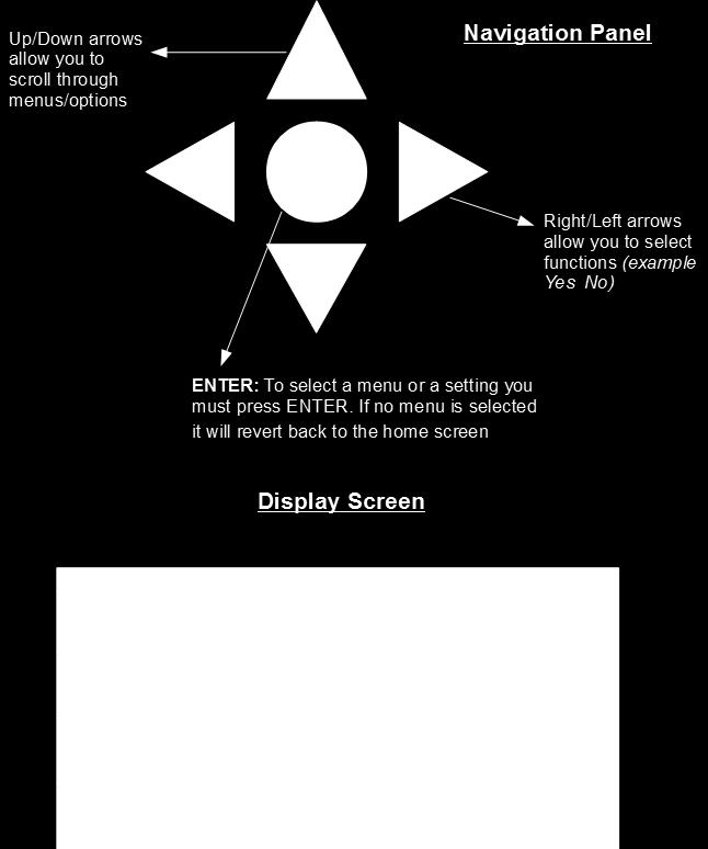
9 System Operating Status The Normal Operation LED must be blinking to indicate the NexPump system is operating. If it is NOT blinking then there may be problem with the NexPump system. Mode Selection Primary Mode This should be used when pump is the primary pump. NexPump WILL NOT display or sound an alarm if pump(s) are activated. Backup Mode Should be used when pump is a backup pump Mode switch in down position. The letter B will be blinking in the mode position on display. NexPump WILL display and sound an alarm if pump(s) are activated. Note: To select or change a mode it can be found under the configuration menu. Use the left and right arrows and press ENTER when cursor is over desired position. Manual Mode Will manually turn on both pumps Switch in up position manual mode is ON and in down position manual mode is OFF. When operating on battery power the NexPump will not calculate battery life remaining. Clog or vapor lock detection is disabled. Pumps will turn off for 5 seconds each minute to clear possible vapor lock conditions. Auto self-test is disabled Emergency Mode Will automatically be selected Mode Emergency will be displayed on the first line of the unit. Alarm will sound with display indicating the reason NexPump went into the Emergency mode. Mode Emergency Alert 1 of 1 Note: The Emergency mode is automatically selected if the NexPump detects certain conditions. Below is an example of the display when operating in the emergency mode. Pump Operation The NexPump system can only be used with a NexPump specified pump. The Single pump units (Ai Single, Ai Jet) must be plugged in to the pump 1 slot. The Ai Turbo Pump 1 (red loomed pump) has to be plugged in to the Pump 1 slot. Make sure all pumps are plugged in properly. Possible Pump Alerts Pump is off- pump is not currently pumping Pump is on- pump is currently running Pump Activated (backup mode only) - pump needed to run Pump Problem (Low) - pump may be defective or not working correctly. The system will specify which pump number. Pump Problem (High) - pump may be defective or not working correctly. The system will specify which pump number. Pump Problem (Run) - circuit board issue. The system will specify which pump number. Pump is over hour lifespan- pump has gone over its expected life span of 2500 hours. Possible Plumbing Alerts Vapor Lock- This alert indicates there may be air trapped in the discharge plumbing. It may also indicate Sensor 1 is stuck in the 9
10 up position. If a check valve is used, check for a proper vent hole in the pump discharge pipe or check if the vent hole is clogged. Clog Alerts- This alert indicates a possible clog in the plumbing discharge. Verify the discharge is clear of obstructions. In the winter it may indicate a frozen discharge pipe. If Notification is installed Notification will occur on all pump alerts after approximately five minutes, with the exception of (Pump Activation) which will occur after approximately thirty minutes. Clear Pump Alerts To clear any pump alert use the navigation panel up and down arrows to find the menu clear alarms. Press ENTER to select. Testing Pumps are tested on 12 hour self-tests or manual tests. Pump 1=0000H (00) Type= H Pump 2=0000H (00) Type= H Pump Hours/Type This screen has the current stats of your pumps. This can be found in the information menu. Pump 1= is the current run hours on pump 1 Pump 2= is the current run hours on pump 2 Type= will either have an H or U depending on the system. H' = High capacity, 'U' = Ultra capacity) (00)= indicates how many times the pump has gone over 2500 hours. The pump is rated at 2500 hours. Sensor Operations Sensor Operation Sensor 1 runs and operates each pump independently. Sensor 2 DOES NOT operate the same as Sensor 1. An active Sensor 2 will double-beep for approximately sixty seconds before a High Water Alert is triggered. You can test the operation of Sensor 1 by lifting the float and verifying Pump 1 turns on. Sensor 2 can be tested by lifting the float and verifying a double-beep from the NexPump System Unit. Note: The gray sensor should be used as Sensor 1. Sensor 1 should be installed as the lower of the two sensors. The white sensor should be used for Sensor 2 and should be installed 4-6 inches higher than sensor 1. Testing Sensors are continually monitored. If Notification is installed Notification will occur on all sensor alerts after approximately five minutes, with the exception of a (High Water Alert) which will occur in approximately one minute. Clear Sensor Alerts Sensor alerts will clear automatically when condition is corrected. Sensor Displaying Disconnected Verify the sensors are plugged in and wires are attached to each connector. If the sensors are connected correctly, the sensor may be defective. AC Power AC Power Operation The NexPump runs on AC power as long as AC is available. During an AC Power outage the NexPump will automatically switch to battery power. The NexPump will display AC Power problem and sound its alarm. If the alarmed is silenced the system will still display alerts. When power is restored the alarm will turn off automatically. Testing AC Power is continually monitored. 10
11 If Notification is installed Notification will occur on AC Power loss after approximately thirty minutes. Clear AC Power Alerts AC power alerts will clear automatically when condition is corrected. AC Power Loss If the NexPump is alerting about an AC Power loss and there is not an issue with the AC Power in your household, you should check the electrical outlet the NexPump AC Power cord in plugged into with a portable device to check if the electrical outlet is live. If the electrical outlet is live then there may be an issue with the internal power supply in the NexPump system unit. IMPORTANT: The power supply is not field serviceable. Do not attempt to disassemble the NexPump or power supply. Testing Manual Self-Test? The NexPump schedules an automatic self-test every 12 hours. A manual test can be done by selecting the menu manual self-test. The self-test feature will test pumps, battery, electronics, etc. To run a manual self-test use the up, down arrows and select the menu manual self-test by pressing ENTER. Reset Self-Test Time Hour? 12 AM/PM Resetting the self-test time can be found in the reset menu or can be performed with command console on internet versions. Resetting should be performed at the time you want the self-test to begin. Once reset the automatic self-test will start at the new time. To change the self-test time of the system use the left and right arrows to adjust the time. When on desired time press ENTER to set. The system self-tests every twelve hours so this will be the time for AM and PM. Battery Battery Specifications The NexPump requires a deep-cycle marine battery. A 105 amp hour or greater rating is required. This is usually a group 27 or group 31 deep-cycle marine battery. Multiple Batteries: Two batteries may be connected in PARALLEL to increase time on battery power. This configuration is highly recommended. IMPORTANT: DO NOT CONNECT BATTERIES IN SERIES. CONNECTING MULTIPLE BATTERIES IN SERIES WILL DAMAGE THE UNIT AND VOID THE WARRANTY. Testing Battery is tested on 12 hour self-tests or manual tests. Exceptions: Charge system is active, battery disconnected or battery replacement alert is active. If Notification is installed Notification will occur on a battery disconnected or low battery or battery replacement alert after approximately five (5) minutes. After an AC Power Outage when running on battery, Notification will occur after approximately thirty (30) minutes. 11
12 Battery Connected Improperly If the battery cables are connected to the wrong posts, the Reversed Polarity red LED will illuminate and an alarm will sound for 'Battery Problem. Note: Correct by reversing the battery cables. Battery Type? W A W=Wet A=AGM,Gel Battery Type Be sure to select the battery type installed with the system. This screen can be found under the configuration menu. Use the left, right arrows and press ENTER when cursor is over desired position. Battery Amps? 105AH Battery Amp Hours Select the battery amp hours on your battery. If multiple batteries are connected add the total amp hours together. This can be found in the configuration menu. Use the right and left arrows to increase or decrease amp hours. When on desired number press ENTER. Charger? On Off Battery Charger The charger should be turned on when the system is first installed or when replacing the batteries. This can be found in the configuration menu. Use the left, right arrows and press ENTER when cursor is over desired position. Reset Battery Timer? Confirm? Y N Battery Timer Batteries have a lifespan and should be replaced when the NexPump reports this time frame has expired. This should also be reset when replacing batteries. Defaults for battery type selected. (WET = 1300 days, 3.5 years, AGM = 1600 Days, 4.5 Years) This can be found in the Reset menu. To select use the left and right arrows and press ENTER when cursor is over desired position. BA=105 AH E/S=On Batt=Wet Replace Battery In: 1350 Days Battery Information This screen can be found under the information menu. BA=current amp hours of your battery Batt=battery type Replace battery= how many days until the system recommends changing the battery 12
13 Battery Life 333H AC Power Problem Running On Battery Power When AC power is out the system will alert of an AC power problem. It will then indicate how many hours are remaining on the battery. 999 hours is the maximum number displayed. The battery life monitor calculates the remaining life about four times an hour. When running on battery power you should closely monitor the battery life when the hours indicated are ten or below. Battery life will not be accurate if the battery amp hours are not set correctly before the power outage began. You can silence this alarm by using the up, down arrows until the menu silence alarm (24H) appears. To select press ENTER. Once AC power is restored the display will again display a normal status. IMPORTANT: When the battery life is calculated at two hours or below, a 'Low Battery' alarm will sound, in addition a notification will take place if this is the only critical alert. When zero hours are calculated, the pump(s) will no longer operate to prevent total battery discharge. Note: If battery life is LOW and battery power is still needed you should connect a replacement battery at this time. Battery Maintenance: Check fluid levels, if applicable for each installed battery at least once every six months. To fill fluid levels: Remove the cell caps of battery. Add distilled water to each cell. If distilled water is not available, tap water with a low mineral content may be used. NEVER ADD MORE ACID. Fill the battery cell so water is just below the fill cap. Clean battery posts as needed with a 50/50 solution of water and baking soda or a wire brush. Do not allow any cleaning solution to enter the battery. Thoroughly dry the terminals and apply petroleum jelly to terminals as needed. Battery Replace Battery Replacement The NexPump is constantly monitoring the battery state and will fail a battery if any one of several tests are not passed within tolerance. IMPORTANT: Review the safety instructions before proceeding to replace the battery or batteries. 1. Disconnect each battery, you DO NOT need to power off the NexPump system unit. 2. Remove each battery and dispose of properly. 3. Connect each new battery. Attach the battery cables to the battery - the BLACK wire to the NEGATIVE (-) post, the RED wire to the POSITIVE (+) post and tighten securely. IMPORTANT: Verify the Battery Reverse LED is NOT illuminated. If so, reverse connections. 5. Verify battery type and amps under the configuration menu. 6. Turn ON Charger under the configuration menu. Charge Mode F00 Charger Operation Charger System Operation: Charge Rate: 20 Amps The charging circuit is disabled anytime the battery or electric power is disconnected or if both pumps are operating. The charge status can be Full, Trickle, Maintain Mode and Disabled. When the charge is started the display will show Fxx, where the xx is the actual charge rate in amps. The charge is automatically monitored at all times. After a full charge is complete the NexPump unit will go into a trickle charge mode. The display will show Txx where the xx is the charge rate. When the Trickle mode is complete, the NexPump will go into the Maintain Mode. In the Maintain Mode charge rates can be very low and may even display M00 for extended times. It is normal for the 'Maintain Mode to run for multiple days. When the battery is disconnected the charging mode will go into the Disable mode. The display will show D00. Battery Disconnected to Reconnected 13
14 S30- The count in seconds when the charge system will start. This allows time for the battery to be reconnected before the charger starts again. If Notification is installed Notification will occur on all charger system alerts after approximately five minutes. Testing Charger system is tested on 12 hour self-tests or manual tests. Exceptions: Full or Trickle charge is currently active, AC Power is off or battery is disconnected. Charger? On Off Turn Charger On The charger should be turned on when system is first installed or when replacing the batteries. This can be found in the configuration menu. Use the left, right arrows and press ENTER when cursor is over desired position. Charger Problem Charger system problems may also be a result of an AC Power problem while a charger system test was active. In that case use the up, down arrows to find the menu clear alarm and press ENTER. If that is not the case it may indicate a problem with the battery charger system. Note: If the battery is completely discharged the NexPump may display the battery disconnected then count down from five seconds. This may cycle until the battery is at a sufficient level to start the full charge mode. This prevents an overload to the charge system or battery. Internal Cooling Fan Fan Operation The internal fan does not run continually and is only in use when the charging system is active, any pump is in use or it is in the test mode, however the fan will continue to run for some time after any pump has run. Testing The fan is testing during operation, on self-tests and during manual tests. Fan Problem If Notification is installed Notification will occur on any fan alerts after approximately five minutes. Fan Problem A fan problem usually means that the fan is defective and must be repaired. Internal Electronics Primary VRef Alert A Primary VRef Problem indicates an internal hardware problem. This will display as a 'VRef Problem' in the alert line of the display. The NexPump automatically switches over to its backup VRef if this alert is detected. Testing The Primary VRef is continually monitored. If Notification is installed Notification will occur on a Primary VRef alert after approximately five minutes. Clear Primary VRef Alerts Primary VRef alerts will clear automatically when condition is corrected. 14
15 Alerts The NexPump system monitors 38 critical points on the unit. In the case of an alert the system will alarm followed by a notification if you have that option. Normal Alerts Pump Activation AC Power Loss Notifications: After approximately thirty minutes Note: Pump Activation lets you know there may be an issue with your main pump. If you find you have a problem with your main pump you can switch the NexPump mode to 'Primary' until the main pump problem is corrected. Critical Alerts All other alerts After approximately five minutes, except a High Water Alert, which is approximately one minute. Silencing or Un-Silencing the Alarm The alarm can be silenced for normal alerts only. It will silence for 24 hours. A silenced alarm clears automatically after 24 hours. Silence Alarm? (24H) To silence or unsilence alarm press Enter when on menu Silence Alarm (24H) or unsilence alarm. Note: When the alarm is silenced the alerts will blink to notify which conditions are in the alarm state. Disable Alarm? (5D) Disabling or Enabling the Alarm The alarm can be disabled if needed. When disabled, the alarm will not sound for any reason. The alarm will stay disabled for five days and automatically be enabled after that time. You can enable the alarm before the five day period by selecting the Enable Alarm menu and pressing ENTER. Note: All notifications will take place while the alarm is disabled, disabling the alarm simply turns off the sound. Alert History Display? Y N Alert History Under the information menu you can retrieve the history of the last ten alerts registered. The date and time will be displayed with the alert. To find the alert history select the information menu and once on the screen Alert History Display use the left and right arrows to move the cursor then press ENTER. Displaying Alerts: Below are two examples of what the display will look like when there are alerts on the NexPump. Line two of the display will show you each alert approximately every three seconds. The first example will let you know the number of alerts and the current number it will be displaying. The format will be 'Alert x of x'. The second example is the actual alert that follows the first example. 15
16 Alert 1 of 1 Sensor 2 Problem Clearing, Silencing, Disabling Alarms To clear the alarm use the up, down arrows to find the menu clear alarm. To select press ENTER. Clear Alarm? The alarm can be silenced for normal alerts only. These include Pump Activation and AC Power Loss. A silenced alarm clears automatically after twenty four hours. Silence Alarm? (24H) To silence the alarm use the up, down arrows to find the menu silence alarm. To select press ENTER. Note: When the alarm is silenced the alerts will blink to notify which conditions are in the alarm state. If the alarm is silenced you can unsilence it by selecting the menu unsilence alarm. UnSilence Alarm? To unsilence the alarm use the up, down arrows to find the menu unsilence alarm. To select press ENTER. Disable Alarm? (5D) The alarm can be disabled if needed. When disabled, the alarm will not sound for any reason. The alarm will stay disabled for five days and automatically be enabled after that time. You can enable the alarm before the five day period. To disable the alarm use the up, down arrows to find the menu disable alarm. To select press ENTER. It will ask to confirm disabling the alarm, use the left, right arrows to select desired position then press ENTER. Note: All notifications will take place while the alarm is disabled, disabling the alarm simply turns off the sound. 16
17 If the alarm is disabled you can enable it by selecting the menu enable alarm. Enable Alarm? To enable the alarm use the up, down arrows to find the menu enable alarm. To select press ENTER. Configuration Menu Note: If you have a notification unit please see the Notification Guide for additional screens. The configuration menu allows unit specific information to be input into the system. Battery, amps, charger, etc. Configuration Menu? To select the configuration menu use the up, down arrows until you see configuration menu on the third display line then press ENTER. Battery Type? W A W=Wet A=AGM,Gel Select the battery type currently on your system. Press ENTER when cursor is over desired position. Battery Amps? 105AH Select the battery amp hours on your battery. If multiple batteries are connected add the total amp hours together. Use the right and left arrows to increase or decrease amp hours. When on desired number press ENTER. Charger? On Off Charger will turn on the battery charger if selected. It is recommended to turn on the charger when system is first installed or when replacing batteries. Press ENTER when cursor is over desired position. 17
18 Mode? Back Prim There are two types of modes to select. Primary Mode Should be used when pump is the primary pump. NexPump WILL NOT display or sound an alert if pump(s) are activated. Backup Mode - Used when pump is a backup pump. NexPump WILL display and sound an alarm if pump(s) are activated. To select a mode use the left and right arrows and press ENTER when cursor is over desired position. Information Menu Note: If you have a notification unit please see the Notification Guide for additional screens. The information menu has specific information on your system including stats, serial number, alert history, etc. Information Menu? To select the information menu use the up, down arrows until you see information menu on the third display line, then press ENTER. System Type SN-NPB Version Type First line will display current system type. SN= stands for the serial number of the system The last line will indicate the current version of the system. Pump 1=0000H (00) Type= H Pump 2=0000H (00) Type= H This screen has the current stats of your pumps Pump 1= is the current run hours on pump 1 Pump 2= is the current run hours on pump 2 Type= will either have an H or U depending on the system. H' = High capacity, 'U' = Ultra capacity) (00)= indicates how many times the pump has gone over 2500 hours. The pump is rated at 2500 hours. CPU=00123 Days TPU=00123 Days Auto Tests=00123 Man Tests=00123 CPU=current power up days of the system TPU= total power up days of the system Auto Tests= amount of self-tests the system has preformed Man Tests= amount of manual tests the system has preformed Man Tests= amount of manual tests the system has preformed 18
19 BA=105 AH E/S=On Batt=Wet Replace Battery In: 1350 Days BA=current amp hours of your battery E/S=empty sump option Batt=battery type Replace battery= how many days until the system recommends changing the battery Time=12:12AM/PM Date= Current time and date set to the system. Note: Notification systems will automatically set the date and time. Alert History Display? Y N Alert history will display the last ten alerts of the system. It will display the alert as well as the date and time the alert occurred. Advanced Menu Note: If you have a notification unit please see the Notification Guide for additional screens. To select the advanced menu use the up, down arrows until you see advanced menu on the third display line, then press ENTER. Advanced Menu? Empty Sump? On Off The empty sump option will pump the water out of the pit after each 12 hour self-test. This is useful so no standing water is left in the pit especially when the NexPump is a backup pump for another pump that could corrode. To select use the left and right arrows and press ENTER when cursor is over desired position. 19
20 Reset Menu Note: If you have a notification unit please see the Notification Guide for additional screens. The reset menu allows you to change or reset the time, date, timers, etc. Reset Menu? To select the reset menu use the up, down arrows until you see reset menu on the third display line, then press ENTER. Set Time? Y N Time=12:12 AM/PM This will allow you to set the current time on the system. If you want to set the time select the Y and use the up, down arrows to adjust the time. Note: the up, down arrows will adjust the time and the left, right arrows will move the cursor. Set Date? Y N Date= This will allow you to set the current date on the system. If you want to set the date select the Y and use the up, down arrows to adjust the time. Note: the up, down arrows will adjust the time and the left, right arrows will move the cursor. Reset Self-Test Time Hour? 12 AM/PM To change the self-test time of the system use the left and right arrows to adjust the time. When on desired time press ENTER to set. The system self-tests every twelve hours so this will be the time for AM and PM. Reset Battery Timer? Confirm? Y N Batteries have a lifespan and should be replaced when the NexPump reports this time frame has expired. This should also be reset when replacing batteries. Defaults for battery type selected. (WET = 1300 days, 3.5 years, AGM = 1600 Days, 4.5 Years) To select use the left and right arrows and press ENTER when cursor is over desired position. 20
21 Quick Reference Guide Power OFF 1. Disconnect Battery a. Disconnect (+) Positive Cable (Red) b. Disconnect (-) Negative Cable (Black) 2. Unplug NexPump s AC Power Cord Power ON 1. Plug in the AC Power Cord FIRST! 2. Connect Battery a. Connect (-) Negative Cable (Black) b. Connect (+) Positive Cable (Red) c. Verify Battery Reverse Indicator Manual Override Mode 1. Set Override switch to up position. 2. Pump(s) should turn on. 3. Battery life will not be calculated. 4. Clog or vapor lock detection is disabled. 5. Set Override switch to down position to turn pump(s) off and return to normal. Clear Alarm(s) To clear the alarm use the up, down arrows to find the menu clear alarm. To select press ENTER. Silence Alarm To silence the alarm use the up, down arrows to find the menu silence alarm (24H). To select press ENTER. Note: Automatically cleared after 24 hours. Alarm will only silence for 'Pump Activated' and AC Power Problems Alarms UnSilence Alarm If the alarm is silenced you can unsilence it by selecting the menu unsilence alarm. To unsilence the alarm use the up, down arrows to find the menu unsilence alarm. To select press ENTER. Manual Test To run a manual self-test use the up, down arrows to find the menu manual self-test. To select press ENTER. Retrieve Serial Number The NexPump serial number is located on a card on the top of the unit or a sticker on the rear of the unit. Battery Amp Hours Setup 1. Use the up, down arrows to find the configuration menu. Select it by pressing ENTER. 2. Wait for the screen Battery Amps? 3. Use the left and right arrows to increase or decrease the amps. Press ENTER when on correct amps. Stats Information The stats can be found under the information menu. Use the up and down arrows to find the information menu. Select it by pressing ENTER. Disable Alarm To disable the alarm use the up and down arrows to find disable alarm (5D). Select it by pressing ENTER. To confirm it use the left and right arrows until the cursor is over the desired position. Select it by pressing ENTER. Enable Alarm If the alarm is disabled you can re-enable it by using the up and down arrows to find enable alarm. Select it by pressing ENTER. Reset Battery Timer 1. Use the up, down arrows to find the reset menu. Select it by pressing ENTER. 2. Wait for the screen Reset Battery Timer Confirm? 3. Use the left and right arrows until the cursor is over the desired position. Select it by pressing ENTER. 21
22 Maximum input/output levels Input: AC Ai Extreme, Ai Dual Full Load 115 Volts 8.5 amps Standby Load 115 Volts 0.17 amps Ai Single Full Load 115 Volts 4.5 amps Standby Load 115 Volts 0.17 amps Charge Output 20 Amps Operating Temperature 9ºC~38ºC (48ºF~100ºF) Storage Temperature 0ºC~38ºC (32ºF~100ºF) NexPump Specifications 22
23 LIMITED WARRANTY: This NexPump, Inc. product is warranted against defects in workmanship and materials. If any failure of these components, resulting from a defect in either workmanship or material shall occur under normal use within THREE YEARS (3) from the original date of purchase for Ai Extreme Series Pumps and Ai Dual or under normal use within TWO YEARS (2) from the original date of purchase for the Ai Single, such failure shall be corrected free of charge to the original purchaser by repair or, at NexPump's sole option, replacement of the defective part or parts. No charge shall be made for labor or services performed during the said warranty period providing the defective product is sent prepaid to our Authorized Service Station. NexPump, Inc. will either repair or at its sole option, replace any such part except for fuses, circuit breakers under normal and proper use. This warranty does not cover High Capacity pumps that have exceeded hours of operating time or Ultra Capacity pumps that have exceeded hours of operating time and does not cover equipment, which had been tampered with in any way, or to damage caused by accident, negligence, alteration, misapplication or natural disasters. This product must be returned transportation prepaid, properly packed and insured. NexPump, Inc. bears transportation cost of the repaired product back to the purchaser. This warranty applied only to the original purchaser. NO OTHER WARRANTIES ARE EXPRESSED OR IMPLIED. NEXPUMP, INC. IS NOT LIABLE FOR CONSEQUENTIAL DAMAGES. EXCEPT AS SET FORTH HEREIN, THERE ARE NO WARRANTIES, EXPRESS OR IMPLIED, WITH RESPECT TO NEXPUMP PRODUCTS. NEXPUMP, INC. EXPRESSLY EXCLUDES AND DISCLAIMS ANY IMPLIED WARRANTY OF MERCHANTABILITY AND ANY WARRANTIES OF FITNESS FOR A PARTICULAR PURPOSE, APPLICATION OR USE. UNDER NO CIRCUMSTANCES WILL THE COMPANY BE LIABLE FOR SPECIAL, INCIDENTAL OR CONSEQUENTIAL DAMAGES, WHETHER SUCH DAMAGES ARE SOUGHT IN CONTRACT, IN TORT (INCLUDING BUT NOT LIMITED TO NEGLIGENCE AND STRICT LIABILITY) OR OTHERWISE, AND THE COMPANY'S LIABILITY SHALL IN NO EVENT EXCEED THE PURCHASE PRICE OF THE NEXPUMP PRODUCTS ON WHICH SUCH LIABILITY IS BASED. 23
24 24
25 25
26 26
ion Genesis Pump Controller
 High Water Alarm Document No.: IONG_OM Page 1 of 7 Table of Contents Safety Precautions.......................... 1 General Overview.......................... 1 Installation.................................2
OPERATION MANUAL Dated: 04/09/2018 Document Name: SHV _OM Page 1 of 8. Ion Technologies SHV40, 75 & 100 Sewage Ejector Pump SAFETY WARNINGS
 Ion Technologies SHV40, 75 & 100 Sewage Ejector Pump Page 1 of 8 biohazard risk exists. Installer(s) and/or service personnel must use proper Personal Protective Equipment and follow handling procedures
DUAL VOLTAGE REFRIGERATORS 220/240 VOLTS AC AND 12/24 VOLTS DC INSTALLATION AND OWNER S MANUAL
 DUAL VOLTAGE REFRIGERATORS 220/240 VOLTS AC AND 12/24 VOLTS DC INSTALLATION AND OWNER S MANUAL Service Information If service or parts are required, contact the nearest Norcold Service Center. To find
FLCH4R Garage and Utility Electric Heater
 FLCH4R Garage and Utility Electric Heater Installation, Operation & Maintenance Instructions Model No. Volts Amps Watts BTU/HR Phase High Low High Low High Low Min Fuse Size* FLCH4R 208 17.3 8.66 3600
Ion Genesis II Pump Controller Digital Level Control with Pump Alternation and High Water Alarm
 Page 1 of 8 General Overview Thank you for purchasing an Ion Genesis controller. Take the time to read the instructions carefully before using this appliance. We strongly recommend that you keep this instruction
2 INLET / HIGH HEAD DRAIN PUMP SYSTEMS MODELS , INSTALLATION INSTRUCTIONS PREINSTALLATION CHECKLIST
 Your Peace of Mind is Our Top Priority Product information presented here reflects conditions at time of publication. Consult factory regarding discrepancies or inconsistencies. MAIL TO: P.O. BOX 637 Louisville,
Single Phase Simplex SXL21=3, SXL24=3, SXH21=3, and SXH24=3
 Single Phase Simplex SXL21=3, SXL24=3, SXH21=3, and SXH24=3 Manufactured by SJE-Rhombus Installation Instructions and Operation/Troubleshooting Manual 7000 Apple Tree Avenue Bergen, New York 14416 Phone:
VX SERIES Wireless Thermostat with Occupancy Sensor
 VX SERIES Wireless Thermostat with Occupancy Sensor INSTRUCTION MANUAL Table of Contents Thermostat Installation... 7 Installing the Wireless Control Card...8 Mounting the thermostat to the wall...9 Thermostat
Sump Pumps Instruction Manual & Safety Warnings
 Important Safety Instructions SAVE THESE INSTRUCTIONS. This manual contains important SAFETY WARNINGS and OPERATING INSTRUCTIONS. You will need to refer to it before attempting any installation or maintenance.
36 IN. ELECTIC FIREPLACE FMI MODEL # LEF36 Mounting Base Feet and Wall Mounting Bracket Included
 F3610G FMI PRODUCTS, LLC 36 IN. ELECTIC FIREPLACE FMI MODEL # LEF36 Mounting Base Feet and Wall Mounting Bracket Included FMI Products, LLC TABLE OF CONTENTS Safety Information... 3 Operating Instructions...
BL250. Pulse Blender OWNER S GUIDE
 BL250 OWNER S GUIDE Pulse Blender 1-877-646-5288 IMPORTANT SAFETY INSTRUCTIONS For Household Use Only WHEN USING ELECTRICAL APPLIANCES, BASIC SAFETY PRECAUTIONS SHOULD ALWAYS BE FOLLOWED, INCLUDING THE
OWNER S MANUAL. FLAT PANEL FIREPLACE HEATER Model Number: Serena (EF202A) WARNING CAUTION
 WARNING CAUTION") FLAT PANEL FIREPLACE HEATER Model Number: Serena (EF202A) OWNER S MANUAL WARNING Read and understand this entire owner s manual, including all safety information, before plugging in or using this product.
FLAT PANEL FIREPLACE HEATER Model Number: Serena (EF202A) OWNER S MANUAL WARNING Read and understand this entire owner s manual, including all safety information, before plugging in or using this product.
SF-707 MIGHTY STEAM IRON OWNER S GUIDE
 SF-707 MIGHTY STEAM IRON OWNER S GUIDE IMPORTANT SAFETY INSTRUCTIONS READ ALL INSTRUCTIONS BEFORE USING WARNING To reduce risk of burns, electrocution, fire, or injury to persons: Do not tamper with or
BEFORE USE, PLEASE READ AND FOLLOW ALL SAFETY RULES AND OPERATING INSTRUCTIONS.
 INSTRUCTION MANUAL Model Number: BLZ-SSRF130 BEFORE USE, PLEASE READ AND FOLLOW ALL SAFETY RULES AND OPERATING INSTRUCTIONS. 1 TABLE OF CONTENTS REFRIGERATOR SAFETY 3 IMPORTANT SAFEGUIDES 4 PARTS AND FEATURES
SOLO OWNERS MANUAL, OPERATING INSTRUCTIONS & INSTALLATION INSTRUCTIONS
 SOLO OWNERS MANUAL, OPERATING INSTRUCTIONS & INSTALLATION INSTRUCTIONS READ MANUAL BEFORE OPERATING SYSTEM Read the owner s manual thoroughly before operating to ensure the most efficient use of the system.
High-Velocity Floor Fan
 High-Velocity Floor Fan Owner s Manual WARNING: Read carefully and understand all ASSEMBLY AND OPERATION INSTRUCTIONS before operating. Failure to follow the safety rules and other basic safety precautions
ScrubMaster 26C OPERATING & MAINTENANCE
 ScrubMaster 26C INTRODUCTION OPERATING & MAINTENANCE INSTRUCTIONS READ THIS BOOK This operator s book has important information for the use and safe operation of this machine. Read this book carefully
Whynter Portable Ice Maker 33 lb capacity - White
 Whynter Portable Ice Maker 33 lb capacity - White Model # : IMC-330WS INSTRUCTION MANUAL Congratulations on your new Whynter product. To ensure proper operation, please read this Instruction Manual carefully
Industrial Vacuums, Inc
 Instructions/Spare Parts Manual Nilfisk Model GWD255 Drum Top Vacuum CAUTION: This Nilfisk vacuum cleaner is not to be used in explosion-hazardous areas, as serious injury could result. Under no circumstances
Use and Care Instructions
 Garment Steamer/Iron Model GI460 W 115/120V., 60 Hz., 230/240 V., 50 Hz. 800 Watts/870 Watts Use and Care Instructions Congratulations! You are the owner of a Garment Steamer/Iron. To fully enjoy the advantages
NO VENTING REQUIRED 120V AC;
 ELECTRIC FIREPLACE Model Number: Alice (EF172B-EF176B) OWNER S MANUAL WARNING Read and understand this entire owner s manual, including all safety information, before plugging in or using this product.
Ion Endeavor Pump Controller Digital Level Control with Pump Alternation and High Water Alarm
 Ion Endeavor Controller Digital Level Control with Alternation Page 1 of 8 General Overview The Ion Endeavor is a pump controller that senses a water level of up to 72", has a configurable water level/pump
VENTILATION FAN WITH LED LIGHT AND HEATER MODEL RAD110LED
 VENTILATION FAN WITH LED LIGHT AND HEATER MODEL RAD110LED TABLE OF CONTENTS Package Contents Important Instructions Preparation Assembly Instructions Wiring Instructions Operating Instructions Care and
e Bath Fan with Light User s Guide
 e Bath Fan with Light User s Guide abfl100rnl, BFL125RNL Item Stock Number(s): BFL100RNL, BFL125RNL IMPORTANT INSTRUCTIONS - OPERATING MANUAL READ AND SAVE THESE INSTRUCTIONS READ CAREFULLY BEFORE ATTEMPTING
PUREPOWER SERIES CENTRAL VACUUM POWER UNITS PP500, PP600 & PP650
 USER GUIDE PUREPOWER SERIES CENTRAL VACUUM POWER UNITS PP500, PP600 & PP650 AB0039 FOR RESIDENTIAL USE ONLY!! BROAN-NUTONE LLC; HARTFORD, WISCONSIN WWW.NUTONE.COM 1-888-336-3948 REGISTER YOUR PRODUCT ONLINE
Air Cleaning Equipment, Inc. 303 N. Main St. Broadway, NC iers.com
 Read and Save These Instructions Horizon Galaxy - Installation and Operations Manual Air Cleaning Equipment, Inc. 303 N. Main St. Broadway, NC 27505 www.horizondehumidif iers.com 1 Safety Notes: The Horizon
R Series B & T2 Model
 FRONT R Series B & T2 Model Fan Forced Wall Heaters 4-1/4 (108mm) NOTE: Knockouts in top same dimensions 3-1/4 3-1/4 (108mm) (108mm) as bottom 16-7/8 (429mm) 13-7/8 (352mm) BOTTOM 13-7/8 (352mm) 7-3/4
CD6102 / CD6102 OC / CD6102-2
 PreView Display CD6102 / CD6102 OC / CD6102-2 Operating Manual www.previewradar.com PATENTS Patented under one or more of the following U.S. Patents: 5345471, 5523760, 5457394, 5465094, 5512834, 5521600,
BLT-999W-2 Item # 60757
 BLT-999W-2 Item # 60757 2 Read these instructions completely before beginning installation. Failure to follow them could cause a heater malfunction resulting in serious injury and/or property damage. WARNING:
e Bath Fan with Light User s Guide
 e Bath Fan with Light User s Guide abfl125rok Item Stock Number(s): BFL125ROK IMPORTANT INSTRUCTIONS - OPERATING MANUAL READ AND SAVE THESE INSTRUCTIONS READ CAREFULLY BEFORE ATTEMPTING TO ASSEMBLE, INSTALL,
Warranty. Thanks. Thank you for purchasing the Oliso Smart Iron, a safer, smarter way to iron.
 User Manual Warranty Oliso, Inc. warrants that for a period of one year from the date of the original purchase, this product will be free from defects in material and workmanship, when utilized for normal
Three Phase Simplex. Installation (937) Installation Instructions and Operation/Troubleshooting Manual. Installation of Floats.
 Installation Instructions and Operation/Troubleshooting Manual. Installation of Floats.") Three Phase Simplex Installation Instructions and Operation/Troubleshooting Manual This control panel must be installed and serviced by a licensed electrician in accordance with the National Electric Code
Three Phase Simplex Installation Instructions and Operation/Troubleshooting Manual This control panel must be installed and serviced by a licensed electrician in accordance with the National Electric Code
11,000 BTU Portable Air Conditioner with dehumidifier & Fan PE4-11R-03 Operating Instructions. Model No. PE4-11R Soleus Air International
 11,000 BTU Portable Air Conditioner with dehumidifier & Fan PE4-11R-03 Operating Instructions Model No. PE4-11R-03 2006 Soleus Air International Thank you for choosing a Soleus Air Portable Air Conditioner.
STOP. SAFETY INFORMATION Please read and understand this entire manual before attempting to assemble, operate or install the product.
 STOP Power supply required Questions, problems, missing parts? Before returning to your retailer, call our customer service department at 1-800-742-5044, 7:30 a.m. - 5 p.m., EST, Monday - Friday. 115 volts
CABINET INFRARED HEATER
 **WARNING: READ THIS INSTRUCTION MANUAL CAREFULLY BEFORE USE. www.dellaproductsusa.com 909. 344. 2588 CABINET INFRARED HEATER INSTRUCTION MANUAL Item No: 050-HA-50082 Thank you for choosing a DELLA Infrared
Canister Vacuums S6EVO. Operations and Parts Manual. Models: S6EVO
 Canister Vacuums S6EVO Operations and Parts Manual Models: S6EVO 2 IMPORTANT SAFETY INSTRUCTIONS When using an electrical appliance, basic precaution must always be followed, including the following: READ
User Guide. for the Beacon ProActTM 200 System
 TM User Guide for the Beacon ProActTM 200 System BEACON recommends that this product, like all sump pumprelated products, be installed by or under the supervision of a professional plumbing contractor.
HC12W COOL MIST ULTRASONIC HUMIDIFIER OWNER S MANUAL. Read and save these instructions.
 COOL MIST ULTRASONIC HUMIDIFIER HC12W OWNER S MANUAL Read and save these instructions. 2 BECAUSE YOU RE NOT LIKE EVERYONE ELSE And neither are we. Always at the forefront of our industry, our goal is to
ELECTRIC FIREPLACE OWNER S MANUAL
 ELECTRIC FIREPLACE OWNER S MANUAL MODELS EL1346C 4001358 WARNING: If the information in this manual is not followed exactly, a fire or electrical shock may result causing property damage, personal injury
ELECTRIC FIREPLACE HEATER MODEL EF-BLT09 OWNER S MANUAL
 ELECTRIC FIREPLACE HEATER MODEL EF-BLT09 OWNER S MANUAL NO VENTILATION REQUIRED PRODUCES SAFE AND EFFICIENT HEAT 110/120-VOLT 60Hz LED BULBS SAVE THESE INSTRUCTIONS FOR FUTURE USE 1 CONSUMER SARETY INSTRUCTIONS
MN908 No. 282C Replaces 282B LB7013
 No. 282C Replaces 282B LB7013 Instruction Manual For Baldor Dust Control Units Models DC7, DC7 3, DC8, DC8 3, DC10, DC10 3, DC12, DC12 3 and DC14 3. For use on Grinders mounted to GA16 and GA20 pedestals
3-in-1 Cooking System
 MC750 OWNER S GUIDE 3-in-1 Cooking System www.ninjakitchen.com IMPORTANT SAFETY INSTRUCTIONS For Household Use Only WHEN USING ELECTRICAL APPLIANCES, BASIC SAFETY PRECAUTIONS SHOULD ALWAYS BE FOLLOWED,
SA SIREN AMPLIFIER
 Carson Manufacturing Co., Inc. 5451 North Rural Street Indianapolis, IN 46220 Phone: (888) 577-6877 Fax: (317) 254-2667 www.carsonsirens.com SA-365-10 SIREN AMPLIFIER Y E L P STANDBY SA-365 W AI L OUTPUT
Model 4001 Series Single Channel Controller
 Model 4001 Series Single Channel Controller Sierra Monitor Corporation 1991 Tarob Court, Milpitas, CA 95035 (408) 262-6611 (800) 727-4377 (408) 262-9042 - Fax E-Mail: sales@sierramonitor.com Web site:
IMpORTANT SAFETy INSTRUcTIONS
 Table of contents SAFETy SETUp OpERATION MAINTENANcE Safety... 2 Specifications... 4 Setup... 4 Operation... 6 WARNING SyMBOLS AND DEFINITIONS Maintenance... 9 Parts List and Diagram... 10 Warranty...
Outdoor/Commercial Refrigerator USER S MANUAL
 Outdoor/Commercial Refrigerator USER S MANUAL MODEL Number:BLZ-SSRF40D IMPORTANT:READ THIS USER S MANUAL PRIOR TO CONNECTING POWER AND USE Before the refrigerator is used, it must be PROPERLY POSITIONED,
ELECTRIC FIREPLACE INSTRUCTION MANUAL. Item No: 050-HA Model No. FP405R-QA
 **WARNING: READ THIS INSTRUCTION MANUAL CAREFULLY BEFORE USE. www.dellaproductsusa.com 909. 344. 2588 ELECTRIC FIREPLACE Model No. FP405R-QA INSTRUCTION MANUAL Item No: 050-HA-50099 2 Thank you for choosing
Turbo Stick Vac. OWNER S MANUAL Model EP V., 60Hz., 7.5 Amps.
 OWNER S MANUAL Model EP600 120V., 60Hz., 7.5 Amps. Turbo Stick Vac For information or assistance: EURO-PRO Operating LLC 94 Main Mill Street, Door 16 Plattsburgh, NY 12901 Tel.: 1 866 98SHARK (74275) www.sharkvac.com
Pump Out Vacuums Polyethylene & Steel
 Pump Out Vacuums Polyethylene & Steel Operations and Parts Manual 110 volt receptacle on single motor only Models: 415P-AD 429P-AD 415DS IMPORTANT SAFETY INSTRUCTIONS When using an electrical appliance,
Because you re not like everyone else. MISTING FAN MF18W OWNER S MANUAL
 Because you re not like everyone else. MISTING FAN MF18W OWNER S MANUAL 2 BECAUSE YOU RE NOT LIKE EVERYONE ELSE. And neither are we. Always at the forefront of our industry, our goal is to offer the best
WHYNTER Compressor Cooling Beverage Refrigerator - Stainless Steel
 WHYNTER Compressor Cooling Beverage Refrigerator - Stainless Steel Model Number: JC-88 MODEL# : BR-125SD Instruction Manual Thank you for your purchase of this WHYNTER product. Please read this Instruction
WALL MOUNT ELECTRIC FIREPLACE OWNERS MANUAL
 WALL MOUNT ELECTRIC FIREPLACE EF-BLT13-36 EF-BLT13-42 EF-BLT13-50 EF-BLT13-60 OWNERS MANUAL NO VENTILATION REQUIRED PRODUCES SAFE AND EFFICIENT HEAT PLEASE READ THIS ENTIRE MANUAL BEFORE USING UNIT 120-VOLT
IN-LINE CENTRIFUGAL FAN VENTS VKP PS 125. User`s manual.
 IN-LINE CENTRIFUGAL FAN VENTS VKP PS 125 EN User`s manual www.vents-us.com EN READ AND SAVE THESE INSTRUCTIONS WARNING! TO REDUCE THE RISK OF FIRE, ELECTRIC SHOCK AND PERSONAL INJURY, READ AND UNDERSTAND
Sentry LIQUID LEVEL GAUGE MODEL 200 or 200C OWNER MANUAL REV 1.7 SEPT08 PAGE 1 OF 12
 PAGE 1 OF 12 TABLE OF CONTENTS PAGE 1. SAFETY PRECAUTIONS 1.1. Electrical shock 3 2. APPLICATION 3 3. INSTALLATION 3.1. Mount indoor alarm display 3.2. Mount the outdoor junction box 3.3. Install interconnecting
Because you re not like everyone else. PORTABLE CLEAR ICE MAKER IM200SS OWNER S MANUAL. Manual v1.0
 Because you re not like everyone else. PORTABLE CLEAR ICE MAKER IM200SS OWNER S MANUAL Manual v1.0 2 BECAUSE YOU RE NOT LIKE EVERYONE ELSE And neither are we. Always at the forefront of our industry, our
READ MANUAL BEFORE OPERATING SYSTEM Read the owner s manual thoroughly before operating to ensure the most efficient use of the system.
 READ MANUAL BEFORE OPERATING SYSTEM Read the owner s manual thoroughly before operating to ensure the most efficient use of the system. Attention Installer: Please be sure this manual and warranty information
Sentry LIQUID LEVEL CONTROLLER MODEL 120 OPERATING MANUAL.
 Sentry LIQUID LEVEL CONTROLLER MODEL 120 OPERATING MANUAL www.aquaticsentry.com TABLE OF CONTENTS 1. SAFETY PRECAUTIONS... 3 2. APPLICATION... 3 2.1 HIGH AND LOW LEVEL ALARM 2.2 PUMP DOWN CONTROLLER 2.3
55-Gallon Dispenser Package
 INSTRUCTIONS-PARTS LIST INSTRUCTIONS This manual contains important warnings and information. READ AND KEEP FOR REFERENCE. 308 666 Rev. A Husky 715 55-Gallon Dispenser Package 100 psi (6.9 bar) Maximum
OWNERS MANUAL MODEL EXTERMINATOR VS900 C/R BLACK VAPOR CLEANING SYSTEM SAFETY INSTRUCTIONS OPERATIONS CARE AND MAINTENANCE TROUBLESHOOTING WARRANTY
 OWNERS MANUAL MODEL EXTERMINATOR VS900 C/R BLACK VAPOR CLEANING SYSTEM SAFETY INSTRUCTIONS OPERATIONS CARE AND MAINTENANCE TROUBLESHOOTING WARRANTY BEFORE USING THIS VAPOR CLEANING SYSTEM READ THESE INSTRUCTIONS
Model No.: PS08-01 PS10-01 Ref: KY80 KY100
 8,000/10,000/12,000 BTU Portable Air Conditioner Operating Instructions Model No.: PS08-01 PS10-01 Ref: KY80 KY100 Model No.: PS12-03 Ref: KY120 3119233 V160310 Thank you for choosing a Soleus Air Portable
IMPORTANT INSTRUCTIONS
 IMPORTANT INSTRUCTIONS W Fan Force Electric Space Heater DANGER ELECTRIC SHOCK OR FIRE HAZARD Figure 1 Covers all W Series models WARNING Read Carefully - These instructions are written in an effort to
User s Manual and Warranty Information for Counterweighted Chain Drive ThyssenKrupp Access
 II User s Manual and Warranty Information for Counterweighted Chain Drive ThyssenKrupp Access Part #2139703 Rev. G II Table of Contents Introduction...3 Elevator Overview...4 Description of Features...5-7
MC MC MC MC MC833130
 Pic-A-Vac Model: MC832085 MC833085 MC832105 MC833105 MC832130 MC833130 OPERATION SERVICE PARTS CARE Revised 8/01 FOR COMMERCIAL USE ONLY IMPORTANT SAFETY INSTRUCTIONS When using an electrical appliance,
CT2 Retro Box Installation Instruction Manual
 ` CT Retro Box Installation Instruction Manual November 007 CTB Inc. Warranty CT Retro Box CTB Inc. Warranty CTB Inc. warrants each new product manufactured by it to be free from defects in material or
HI Industrial Utility Heater HI Soleus Air International
 HI1-50-03 Industrial Utility Heater HI1-50-03 2010 Soleus Air International Thank you for choosing a Soleus Air Utility Heater. This owner s manual will provide you with valuable information necessary
Rack Mount Series Installation Guide
 Rack Mount Series Installation Guide Models Include: Maximal1RHV Maximal1RV - 12VDC @ 4 amp or 24VDC @ 3 amp. - 12VDC @ 4 amp or 24VDC @ 3 amp. - Eight (8) Fuse Protected Outputs. - Sixteen (16) Fuse Protected
20 High Velocity Fan with 135 Tilt Head
 20 High Velocity Fan with 135 Tilt Head Model No.: FF-50-A Operating Instructions V.140311 4002234 Thank you for choosing a Soleus Air High Velocity Fan. This owner s manual will provide you with valuable
Sanitaire. Owner s Guide. 10 GALLON Box Extractor SC6088 Series IMPORTANT
 Sanitaire 10 GALLON Box Extractor SC6088 Series Part No. SC6088 Rev 2 (3/14) Owner s Guide IMPORTANT Do not return this product to the store. Call 1-800-800-8975* Monday - Friday 8:00 AM to 7:30 PM and
MULTI-FUNCTION HAND VACUUM INSTRUCTION MANUAL. For Authentic Monster Replacement Parts Call Model #: H056
 MULTI-FUNCTION HAND VACUUM INSTRUCTION MANUAL Call 888.896.8786 Model #: H056 IMPORTANT SAFE T SAVE THESE INSTRUCTIONS When using an electrical appliance, basic safety precautions should always be observed,
1600 Watt Professional
 FOR THE WAY YOU LIVE 1600 Watt Professional Steam Iron Model EP480 USE AND CARE INSTRUCTIONS Congratulations! You are the owner of the Shark 1600 Watt Professional Steam Iron. To fully enjoy the advantages
MODEL ZAC ZONE ANNUNCIATOR/CONTROLLER DESIGNED FOR ZONE ANNUNCIATION AND MONITORING
 MODEL ZAC-32 32 ZONE ANNUNCIATOR/CONTROLLER DESIGNED FOR ZONE ANNUNCIATION AND MONITORING 32 HARD WIRED ZONES CAN BE NORMALLY-OPEN OR NORMALLY-CLOSED ZONE WIRING RUNS CAN BE AS FAR AS 10,000 FEET FROM
ULTRASONIC HUMIDIFIER
 To Buy: Visit www.sylvane.com or call (800) 934-9194 For Product Support: Contact Sunpentown at 1-800-330-0388 ULTRASONIC HUMIDIFIER [ADORABLE MONKEY] To prolong the life of this humidifier, using distilled
Spa Control System OWNER S MANUAL
 LIMITED WARRANTY ONE YEAR LIMITED WARRANTY: UNITED SPAS, INC. warrants, to the original purchaser, the Spa Equipment against defects in materials or workmanship for a period of one year from date of purchase.
Owner s. 18 Misting MF18W. To view
 Owner s Manual MF18W 18 Misting Fan IMPORTANT SAFETY INFORMATION: Please carefully read this manual before attempting to install or use this misting fan. For your safety, comply with all safety instructionss
RATIO:GUARD Model E-1S EC Monitor
 EC probe Probe tees Probe retention clips Temperature probe E-1S monitor box UNPACKING Please open and inspect your package upon receipt. Your package was packed with great care and all the necessary packing
Technical Details. Important Safety Instructions READ ALL INSTRUCTIONS BEFORE USING THIS MACHINE
 SEBO ET-1 Owner's Manual Technical Details Brush motor - 175 watts, 1.6 amps Width: 12 in Weight: 5.4 lbs Brush roller: replaceable Brush drive: toothed belt with electronic overload protection Important
Laing Thermotech. Autocirc The Instant Hot Water Pump Models E1-BCANCT1W-06 and E1-BCANRT1W. Installation & Operating Manual
 Installation & Operating Manual Please read this manual carefully before attempting to install, operate or maintain the product described. Failure to comply with the information provided in this manual
MP-MBA-45T-1/60T-1 / 75T-1
 MASTER Water Conditioning Corp. www.masterwater.com Installation and Operation Manual MP-MBA-45T-1/60T-1 / 75T-1 with the 268/762 Logix Control Valve July 2006 Table of Contents Page No. Topic Description
OWNER S GUIDE
 QB3000SS series OWNER S GUIDE www.ninjakitchen.com IMPORTANT SAFETY INSTRUCTIONS For Household Use Only WHEN USING ELECTRICAL APPLIANCES, BASIC SAFETY PRECAUTIONS SHOULD ALWAYS BE FOLLOWED, INCLUDING THE
e Bath Fan with Light User s Guide
 e Bath Fan with Light User s Guide abfl50uq, BFL60UQ, BFL70, BFL85 Item Stock Number(s): BFL50UQ, BFL60UQ, BFL70, BFL85 IMPORTANT INSTRUCTIONS - OPERATING MANUAL READ AND SAVE THESE INSTRUCTIONS READ CAREFULLY
Model: EF34. Owner's Guide & Installation Manual
 Owner's Guide & Installation Manual WARNING: Read this manual before using this product. Failure to follow the instructions and safety precautions in this manual can result in damage to property, serious
MODEL HBX-1 P/N 3G59332
 MODEL HBX-1 P/N 3G59332 LIMITED WARRANTY Getz Equipment Innovators warrants its products, and component parts of any product manufactured by Getz Equipment Innovators, to be free from defects in material
PORTABLE DEHUMIDIFIER
 PORTABLE DEHUMIDIFIER User s Manual For information or assistance, please contact: Soleus International 9451 Telstar Ave. El Monte, CA 91731 Tel: 1-888-876-5387 www.soleusair.com POWERED BY: KEEP THESE
Upholstery and Drapery Cleaner. Operator and Parts Manual. Model No.: gal Extractor. MNL32506 Rev. 00 (08-98)
") 32506 Upholstery and Drapery Cleaner Model No.: 32506 3 gal Extractor Operator and Parts Manual KLEENRITE 1122 MAPLE STREET MADERA CA 93637 U.S.A. FAX: 1-559-673-5725 CUSTOMER SERVICE: 1-800-241-4865 MNL32506
32506 Upholstery and Drapery Cleaner Model No.: 32506 3 gal Extractor Operator and Parts Manual KLEENRITE 1122 MAPLE STREET MADERA CA 93637 U.S.A. FAX: 1-559-673-5725 CUSTOMER SERVICE: 1-800-241-4865 MNL32506
NEUTRONICS MINI ID R-1234yf REFRIGERANT IDENTIFIER OPERATION MANUAL
 NEUTRONICS MINI ID R-1234yf REFRIGERANT IDENTIFIER OPERATION MANUAL 456 Creamery Way, Exton, PA 19341, USA Phone: 610.524.8800 Fax: 610.524.8807 Email: info@refrigerantid.com www.refrigerantid.com Page
Garment Steamer Model SC620
 OWNER S MANUAL Garment Steamer Model SC620 For information or assistance: EURO-PRO Corporation 178 West Service Rd. Champlain, NY 12919 1-800-798-7398 www.euro-pro.com IMPORTANT SAFETY INSTRUCTIONS When
ITEM # , , PAWTUCKET CEILING FAN MODEL #40958, 40959, 40047
 ITEM #0803775, 0721899, 0807427 PAWTUCKET CEILING FAN MODEL #40958, 40959, 40047 Harbor Breeze is a registered trademark of LF, LLC. All Rights Reserved. Español p. 20 ATTACH YOUR RECEIPT HERE Serial Number
OWNER S MANUAL ELECTRIC FIREPLACE INSERT. Model No.: WESTERN (EF42D-45D) WARNING CAUTION
 WARNING CAUTION") ELECTRIC FIREPLACE INSERT Model No.: WESTERN (EF42D-45D) OWNER S MANUAL WARNING Read and understand this entire owner s manual, including all safety information, before plugging in or using this product.
ELECTRIC FIREPLACE INSERT Model No.: WESTERN (EF42D-45D) OWNER S MANUAL WARNING Read and understand this entire owner s manual, including all safety information, before plugging in or using this product.
Hades 2. Digital Recycle and Lighting Timer with High Temp Shut-Off Instruction Manual. Notes: 1 Square = Foot/Feet
 Notes: 1 Square = Foot/Feet Hades 2 Digital Recycle and Lighting Timer with High Temp Shut-Off Instruction Manual VANCOUVER, WASHINGTON U.S.A. VANCOUVER, WASHINGTON U.S.A. www.titancontrols.net Revision
Solar Powered Wireless Photobeam Sensors
 Installation & Operating Manual Solar Powered Wireless Photobeam Sensors SWPB-50 SWPB-100 SWPB-250 SWPB-400 50ft 100ft 250ft 400ft Create a Virtual Wall with the photobeam sensors! FEATURES Detection Range:
MaxLite LED High Bay Fixtures
 General Safety Information To reduce the risk of death, personal injury or property damage from fire, electric shock, falling parts, cuts/abrasions, and other hazards read all warnings and instructions
USE AND CARE MANUAL. Before operating the iron, please read these instructions carefully and keep them for future reference.
 USE AND CARE MANUAL Before operating the iron, please read these instructions carefully and keep them for future reference. 1 IMPORTANT SAFETY INSTRUCTIONS When using electrical appliances, basic safety
OWNER S GUIDE
 QB3000SS Series OWNER S GUIDE www.ninjakitchen.com IMPORTANT SAFETY INSTRUCTIONS For Household Use Only WHEN USING ELECTRICAL APPLIANCES, BASIC SAFETY PRECAUTIONS SHOULD ALWAYS BE FOLLOWED, INCLUDING THE
Computer Room Guard Model VM Manual and Installation Instructions
 Computer Room Guard Model VM500-8 Manual and Installation Instructions For units purchased since December 2004 Index Page General Description 3 Installation, Wiring Diagram 3-5 Accessing the Computer Room
Owner's Manual. Please read this document carefully before installing and/or using your vacuum cleaning system.
 Owner's Manual for household use only Please read this document carefully before installing and/or using your vacuum cleaning system. Model : Serial No : Important Safety Instructions When using an electrical
OWNER'S MANUAL IMPORTANT: READ OWNER'S MANUAL CAREFULLY MODEL : CHEETAH DC2000 FOR YOUR CONVENIENCE, RECORD THE FOLLOWING IMPORTANT INFORMATION MODEL:
 OWNER'S MANUAL IMPORTANT: READ OWNER'S MANUAL CAREFULLY MODEL : CHEETAH DC2000 FOR YOUR CONVENIENCE, RECORD THE FOLLOWING IMPORTANT INFORMATION MODEL: SERIAL NUMBER:-------- DATE PURCHASED: PURCHASED FROM:
Installation and Operation Manual. ACF-18 Automatic Chlorinating Feeder
 Installation and Operation Manual ACF-18 Automatic Chlorinating Feeder Operating Specifications Inlet Flow: 1.0-1.5 gpm Outlet Flow: = Inlet Flow Inlet Pressure: 10-45 psi Maximum Output: 26 lbs. of Available
Alen A350 HEPA Air Purifier USER MANUAL
 Alen A350 HEPA Air Purifier USER MANUAL Table of Contents Air Purifier Safety Using Your Air Purifier Operating Your Unit Identification Of Parts Know Your Air Purifier Care & Maintenance Replacing The
Outdoor Refrigerator USER S MANUAL
 Outdoor Refrigerator USER S MANUAL MODEL Number:BLZ-SSRF-40DH IMPORTANT:READ THIS USER S MANUAL PRIOR TO CONNECTING POWER AND USE Before the refrigerator is used, it must be PROPERLY POSITIONED, LEVELED
MILLA ELECTRIC FIREPLACE
 MILLA ELECTRIC FIREPLACE MODEL NO. 064-3177-0 ASSEMBLY INSTRUCTIONS Toll-free: 1-888-670-6684 IMPORTANT: Please read this manual carefully before beginning assembly of this product. Keep this manual for