Technical Manual. Signalpoint Pro
|
|
|
- Mae McBride
- 6 years ago
- Views:
Transcription


1 Technical Manual Signalpoint Pro
2 1 Safety Ensure that this Operating Manual is read and understood BEFORE installing / operating / maintaining the equipment. Pay particular attention to Warnings and Cautions. All document Warnings are listed here and repeated where appropriate at the start of the relevant chapter(s) of this Operating Manual. Cautions appear in the sections / sub-sections of the document where they apply. WARNINGS SIGNALPOINT PRO IS DESIGNED FOR INTRINSICALLY SAFE INSTALLATION AND USE IN ZONE 1 OR 2 HAZARDOUS AREAS IN EUROPE, AND DIVISION 1 AREA APPLICATIONS IN NORTH AMERICA. INSTALLATION MUST BE IN ACCORDANCE WITH THE RECOGNIZED STANDARDS OF THE APPROPRIATE AUTHORITY IN THE COUNTRY CONCERNED. POWER MUST BE OFF AT THE SOURCE DURING WIRING OPEATIONS (REFER TO CONTROL DRAWING P-1446) FOR INTRINTRINSICALLY SAFE INSTALLATION, TO MAINTAIN INTRINSIC SAFETY, THE TRANSMITTER WIRING MUST BE ROUTED THROUGH A GALVANIC ISOLATOR OR ZENER DIODE BARRIER WHICH MEETS THE ENTITY PARAMETERS INDICATED IN THE CONTROL DRAWING P THE SELECTED BARRIER SHALL BE APPROVED WITH INTRINSICALLY SAFE CIRCUITS FOR THE HAZARDOUS LOCATION CLASS AND GROUP AS APPROPRIATE FOR THE APPLICATION. THE CABLE CAPACITANCE PLUS THE TRANSMITTER CAPACITANCE (Ci) MUST BE LESS THAN OR EQUAL TO THE Ca ON THE BARRIER. THE CABLE INDUCTANCE PLUS THE TRANSMITTER INDUCTANCE (Li) MUST BE LESS THAN OR EQUAL TO THE La ON THE BARRIER. THE BARRIER MUST BE LOCATED IN THE NON-HAZARDOUS AREA. ALL INTRINSICALLY SAFE WIRING SHALL BE KEPT SEPARATE FROM NON-INTRINSICALLY SAFE WIRING. TERMINATE ZENER BARRIER EARTH GROUND TO THE GROUND BUS OF THE POWER DISTRIBUTION PANEL (CONTROLLER). RESISTANCE TO GROUND MUST NOT BE GREATER THAN 1.0 OHM. ELECTRICAL APPARATUS CONNECTED TO AN INTRINSICALLY SAFE SYSTEM MUST NOT USE OR GENERATE MORE THAN 250V (Vrms) WITH RESPECT TO EARTH GROUND. INSTALLATION MUST BE IN ACCORDANCE WITH THE BARRIER MANUFACTURER S INSTRUCTIONS AND WITH ARTICLE 504/505 IN THE NATIONAL ELECTRIC CODE, ANSI/NFPA 70. BARRIER ENCLOSURE MUST MEET REQUIREMENTS OF ANSI/ISA S82 FOR USE IN NON-HAZARDOUS OR CLASS I, DIVISION 2, GROUPS A,B,C AND D HAZARDOUS LOCATIONS. USE A UL LISTED OR NRTL APPROVED DUST TIGHT ENCLOSURE AND CONDUIT FITTINGS APPROPRIATE FOR ENVIRONMENTAL PROTECTION IN CLASS II, DIVISION 2, GROUPS F AND G, AND CLASS III, HAZARDOUS LOCATIONS. ACCESS TO THE INTERIOR OF THE DETECTOR MUST ONLY BE CONDUCTED BY TRAINED PERSONNEL. TO REDUCE RISK OF IGNITION OF HAZARDOUS ATMOSPHERE, FOLLOW THE LIVE MAINTENANCE INSTRUCTIONS. IT IS RECOMMENDED TO BUMP TEST THE SENSORS FREQUENTLY TO ENSURE PROPER OPERATION DO NOT LEAVE UNIT WITH SENSOR INSTALLED UNPOWERED FOR LONG PERIOD OF TIME AT OR BELOW -10 C TAKE CARE WHEN HANDLING SENSORS AS THEY MAY CONTAIN CORROSIVE SOLUTIONS. DO NOT TAMPER OR IN ANY WAY DIS-ASSEMBLE THE SENSOR. DO NOT EXPOSE TO TEMPERATURES OUTSIDE THE RECOMMENDED RANGE. DO NOT EXPOSE SENSOR TO ORGANIC SOLVENTS OR FLAMMABLE LIQUIDS. SENSORS ARE NOT INTENDED FOR USE IN ATMOSPHERES CONTAINING OXYGEN CONCENTRATIONS GREATER THAN 21% BY VOLUME. AT THE END OF THEIR WORKING LIFE, SENSORS MUST BE DISPOSED OF IN AN ENVIRONMENTALLY SAFE MANNER. DISPOSAL SHOULD BE ACCORDING TO LOCAL WASTE MANAGEMENT REQUIREMENTS AND ENVIRONMENTAL LEGISLATION. ELECTROCHEMICAL CELLS SHOULD NOT BE INCINERATED AS THEY MAY EMIT TOXIC FUMES. ALTERNATIVELY, SENSORS MAY BE SECURELY PACKAGED AND RETURNED TO HONEYWELL ANALYTICS CLEARLY MARKED FOR ENVIRONMENTAL DISPOSAL. 1
3 2 Information Honeywell Analytics can take no responsibility for installation and / or use of its equipment if this is not done in accordance with the appropriate issue and / or amendment of the Operating Manual. The reader of this Operating Manual should ensure that it is appropriate in all details for the exact equipment to be installed and / or operated. If in doubt, contact Honeywell Analytics for advice. The following types of notices are used throughout this Operating Manual: WARNING Identifies a hazardous or unsafe practice which could result in severe injury or death to personnel. Caution: Identifies a hazardous or unsafe practice which could result in minor injury to personnel, or product or property damage. Note: Identifies useful / additional information. Every effort has been made to ensure the accuracy of our documents, however, Honeywell Analytics can assume no responsibility for any errors or omissions in our documents or there consequences. Honeywell Analytics greatly appreciates being informed of any errors or omissions that may be found in the contents of any of our documents. For information not covered in this document, or there is a requirement to send comments/corrections about this document, please contact Honeywell Analytics. Honeywell Analytics reserve the right to change or revise the information supplied in this document without notice and without obligation to notify any person or organization of such revision or change. If information is required that does not appear in this document, contact the local distributor/agent or Honeywell Analytics. 2
4 3 Table of contents 1 Safety Information Table of contents Introduction Product overview Transmitter Sensor Accessories Installation Mounting and location of detectors Electrical connections Detector wiring schematics Hazardous Zone 1 or Div 1 installation type Hazardous Zone 1 or Div 1 installation type Terminal connections Maximum cable length calculation Suggested barriers and isolators Cable screening Default configuration First time switch on Setting full scale detection range Changing span calibration point Calibration Zeroing and span calibration of the toxic version detector Calibrating the Oxygen version detector Normal operation Normal operating display Detector fault/message display General normal operation notes General Maintenance Live Maintenance Functional gas test Detector operational life Servicing Sensor replacement General specifications Ordering information Warranty statement CE Certificate Control Drawing Certification Label
5 4 Introduction The Signalpoint Pro gas detector is designed to detect toxic or Oxygen gas hazards that are commonly found in industrial applications. A local display provides gas concentration readings. A magnetic wand and magnetic switch, when used in conjunction with the display, enables non intrusive one man calibration. The detector has an integral IP66 (NEMA 4X) plastic junction box that includes 3 mounting holes thereby eliminating the need for additional mounting brackets. 1 x 21mm diameter clearance cable / conduit entry and 1 x 21mm diameter clearance knockout allow for incoming cable connections. The output is an industry standard 2 wire IS 4-20mA loop. Signalpoint Pro is suitable for connection to a wide range of Honeywell Analytics or 3 rd party control equipment. 4.1 Product overview The Signalpoint Pro detector is supplied as a toxic or Oxygen transmitter with a separate plug in sensor. Sensor Cover Sensor retaining ring Sensor Transmitter lid Transmitter lid screw Terminals Transmitter terminal housing Diagram 1: Signalpoint Pro explode view Transmitter Two versions of transmitter are available; toxic or Oxygen versions. The toxic version is for use with Hydrogen Sulphide, Carbon Monoxide, Sulphur Dioxide, Ammonia, Nitrogen Dioxide and Hydrogen sensors. The Oxygen version is specifically for use with the Oxygen sensor. The removable sensor cover and retaining ring allow sensors to plug into the transmitter without having to open the main terminal housing. The LCD display and 4
6 magnetic switch target are located on the front of the transmitter lid. The hinged lid opens to reveal the large terminal compartment. Additional user programmable features are made using the pushbuttons on the transmitter electronics assembly located on the inside of the transmitter lid Sensor To ensure maximum operating life, the plug-in sensors are supplied in a separate container with each new Signalpoint Detector. When fitted the gas type and default sensor range for each sensor is automatically recognised. Replacement sensors can be simply installed by removing the old sensor and plugging in a new one, even with the unit under power Accessories Calibration gas flow housing The calibration gas flow housing (part number SGPTPPCFA) is used for calibration or sample flow applications. Weatherproof cap A weatherproof cap is available (part number A-1635) to offer additional protection against harsh environments. It also includes a remote gassing nozzle to allow the application of response test gas. Note: this item is not to be used for calibration purposes. Speed of response will be slower with the weather protection fitted. Do not use with the Sulfur Dioxide or Nitrogen Dioxide (SO 2 or NO 2 ) sensor. All accessories are supplied with an installation instruction leaflet. 5
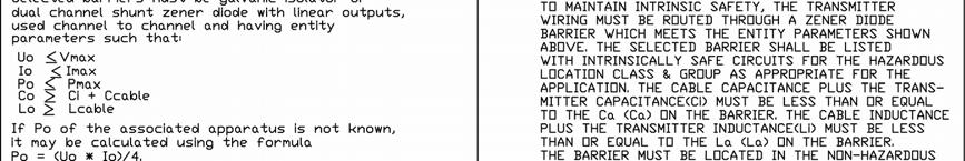
7 5 Installation WARNINGS SIGNALPOINT PRO IS DESIGNED FOR INTRINSICALLY SAFE INSTALLATION AND USE IN ZONE 1 OR 2 HAZARDOUS AREAS IN EUROPE, AND DIVISION 1 AREA APPLICATIONS IN NORTH AMERICA. INSTALLATION MUST BE IN ACCORDANCE WITH THE RECOGNIZED STANDARDS OF THE APPROPRIATE AUTHORITY IN THE COUNTRY CONCERNED. POWER MUST BE OFF AT THE SOURCE DURING WIRING OPEATIONS (REFER TO CONTROL DRAWING P-1446) FOR INTRINSICALLY SAFE INSTALLATION, THE BARRIER AND CONTROLLER MUST BE LOCATED IN A NON-HAZARDOUS AREA. THE SENSOR ASSEMBLY ONLY, SHOULD BE IN THE HAZARDOUS LOCATION. TO MAINTAIN INTRINSIC SAFETY, THE TRANSMITTER WIRING MUST BE ROUTED THROUGH A ZENER DIODE BARRIER WHICH MEETS THE ENTITY PARAMETERS INDICATED IN THE CONTROL DRAWING P THE SELECTED BARRIER SHALL BE APPROVED WITH INTRINSICALLY SAFE CIRCUITS FOR THE HAZARDOUS LOCATION CLASS AND GROUP AS APPROPRIATE FOR THE APPLICATION. THE CABLE CAPACITANCE PLUS THE TRANSMITTER CAPACITANCE (Ci) MUST BE LESS THAN OR EQUAL TO THE Ca ON THE BARRIER. THE CABLE INDUCTANCE PLUS THE TRANSMITTER INDUCTANCE (Li) MUST BE LESS THAN OR EQUAL TO THE La ON THE BARRIER. THE BARRIER MUST BE LOCATED IN THE NON-HAZARDOUS AREA. ALL INTRINSICALLY SAFE WIRING SHALL BE KEPT SEPARATE FROM NON-INTRINSICALLY SAFE WIRING. TERMINATE BARRIER EARTH GROUND TO THE GROUND BUS OF THE POWER DISTRIBUTION PANEL (CONTROLLER). RESISTANCE TO GROUND MUST NOT BE GREATER THAN 1.0 OHM. ELECTRICAL APPARATUS CONNECTED TO AN INTRINSICALLY SAFE SYSTEM MUST NOT USE OR GENERATE MORE THAN 250V (Vrms) WITH RESPECT TO EARTH GROUND. INSTALLATION MUST BE IN ACCORDANCE WITH THE BARRIER MANUFACTURER S INSTRUCTIONS AND WITH ARTICLE 504/505 IN THE NATIONAL ELECTRIC CODE, ANSI/NFPA 70 AND/OR CANADIAN ELECTRICAL CODE SECTION 18. BARRIER ENCLOSURE MUST MEET REQUIREMENTS OF ANSI/ISA S82 FOR USE IN NON-HAZARDOUS OR CLASS I, DIVISION 2, GROUPS A,B,C AND D HAZARDOUS LOCATIONS. USE A UL LISTED OR NRTL APPROVED DUST TIGHT ENCLOSURE AND CONDUIT FITTINGS APPROPRIATE FOR ENVIRONMENTAL PROTECTION IN CLASS II, DIVISION 2, GROUPS F AND G, AND CLASS III, HAZARDOUS LOCATIONS. ACCESS TO THE INTERIOR OF THE DETECTOR MUST ONLY BE CONDUCTED BY TRAINED PERSONNEL REFER TO THE LIVE MAINTENANCE SECTION.. TO REDUCE RISK OF IGNITION OF HAZARDOUS ATMOSPHERE, DISCONNECT THE EQUIPMENT FROM THE SUPPLY CIRCUIT BEFORE REMOVING THE METAL PLATE LOCATED ON THE DETECTOR HOUSING COVER. BEFORE CARRYING OUT ANY WORK ENSURE LOCAL REGULATIONS AND SITE PROCEDURES ARE FOLLOWED. APPROPRIATE STANDARDS MUST BE FOLLOWED TO MAINTAIN THE OVERALL CERTIFICATION OF THE DETECTOR. IT IS RECOMMENDED TO BUMP TEST THE SENSORS FREQUENTLY TO ENSURE PROPER OPERATION DO NOT LEAVE UNIT WITH SENSOR INSTALLED UNPOWERED FOR LONG PERIOD OF TIME AT OR BELOW -10 C TAKE CARE WHEN HANDLING SENSORS AS THEY MAY CONTAIN CORROSIVE SOLUTIONS. DO NOT TAMPER OR IN ANY WAY DIS-ASSEMBLE THE SENSOR. DO NOT EXPOSE TO TEMPERATURES OUTSIDE THE RECOMMENDED RANGE. DO NOT EXPOSE SENSOR TO ORGANIC SOLVENTS OR FLAMMABLE LIQUIDS. AT THE END OF THEIR WORKING LIFE, SENSORS MUST BE DISPOSED OF IN AN ENVIRONMENTALLY SAFE MANNER. DISPOSAL SHOULD BE ACCORDING TO LOCAL WASTE MANAGEMENT REQUIREMENTS AND ENVIRONMENTAL LEGISLATION. ELECTROCHEMICAL CELLS SHOULD NOT BE INCINERATED AS THEY MAY EMIT TOXIC FUMES. ALTERNATIVELY, SENSORS MAY BE SECURELY PACKAGED AND RETURNED TO HONEYWELL ANALYTICS CLEARLY MARKED FOR ENVIRONMENTAL DISPOSAL. 6
8 5.1 Mounting and location of detectors Caution: The location of the detectors should be made in accordance with any relevant local and national legislation, standards or codes of practice. Always replace detectors with a detector of the same type. The detector should be mounted where the gas is most likely to be present. The following points should be noted when locating gas detectors. When locating detectors consider the possible damage caused by natural events e.g. rain or flooding. Consider ease of access for functional testing and servicing. Consider how escaping gas may behave due to natural or forced air currents. Note: The placement of detectors should be determined following the advice of experts having specialist knowledge of gas dispersion, experts having knowledge of the process plant system and equipment involved, safety and engineering personnel. The agreement reached on the location of detectors should be recorded. The hinged transmitter lid, when opened, reveals three mounting holes (suitable for M3.5 or No. 6 screws) thereby removing any need for additional mounting brackets. These mounting holes are outside the weatherproof seal to maintain the IP rating. The hinged lid ensures hands free, unhindered access, to terminals for easy termination of incoming cables. A pre-drilled 21mm diameter clearance entry (LHS) and 21mm clearance knockout (RHS) allow connection via conduit or cable with suitable glands. The use of 2 core screened cable is required to prevent false alarms due to sources of electromagnetic interference. The use of conduit or suitably mechanically protected cabling and compression glands is recommended for any safety related gas monitoring system. Industrial applications will typically use 0.5mm 2 (20AWG) to 1.0mm 2 (16AWG) cross sectional area cable or similar. To mount a Signalpoint Detector use the following procedure: 1. Mark the location of the 3 mounting holes on the mounting surface using the dimensional diagram below. 2. Prepare the mounting holes using appropriate fixings for the type of mounting surface and suitable for M3.5 or No. 6 screws. 3. Open the hinged transmitter lid and align the enclosure mounting holes with the holes in the mounting surface. 4. Secure the enclosure to the surface using the mounting screws. 7
9 83.5mm (3.3 ) 72.5mm (2.85 ) 21mm diameter clearance hole 105mm (4.1 ) 21mm diameter knockout Mounting holes (M3.5 or No.6 screws) 120mm (4.7 ) 150mm (5.9 ) Diagram 2: Detector dimensions and mounting hole locations 8
10 6 Electrical connections WARNINGS SIGNALPOINT PRO IS DESIGNED FOR INTRINSICALLY SAFE INSTALLATION AND USE IN ZONE 1 OR 2 HAZARDOUS AREAS IN EUROPE, AND DIVISION 1 AREA APPLICATIONS IN NORTH AMERICA. INSTALLATION MUST BE IN ACCORDANCE WITH THE RECOGNIZED STANDARDS OF THE APPROPRIATE AUTHORITY IN THE COUNTRY CONCERNED. POWER MUST BE OFF AT THE SOURCE DURING WIRING OPEATIONS. WIRE ACCORDING TO CONTROL DRAWING REQUIREMENTS. (P-1446) FOR INTRINSICALLY SAFE INSTALLATION, THE BARRIER AND CONTROLLER MUST BE LOCATED IN A NON-HAZARDOUS AREA. THE SENSOR ASSEMBLY ONLY, SHOULD BE IN THE HAZARDOUS LOCATION. ALL INTRINSICALLY SAFE WIRING SHALL BE KEPT SEPARATE FROM NON-INTRINSICALLY SAFE WIRING. TERMINATE BARRIER EARTH GROUND TO THE GROUND BUS OF THE POWER DISTRIBUTION PANEL (CONTROLLER). RESISTANCE TO GROUND MUST NOT BE GREATER THAN 1.0 OHM. ELECTRICAL APPARATUS CONNECTED TO AN INTRINSICALLY SAFE SYSTEM MUST NOT USE OR GENERATE MORE THAN 250V (Vrms) WITH RESPECT TO EARTH GROUND. INSTALLATION MUST BE IN ACCORDANCE WITH THE BARRIER MANUFACTURER S INSTRUCTIONS AND WITH ARTICLE 504/505 IN THE NATIONAL ELECTRIC CODE, ANSI/NFPA 7, AND/OR CANADIAN ELECTRICAL CODE, SECTION 18. BARRIER ENCLOSURE MUST MEET REQUIREMENTS OF ANSI/ISA S82 FOR USE IN NON-HAZARDOUS OR CLASS I, DIVISION 2, GROUPS A,B,C AND D HAZARDOUS LOCATIONS. USE A UL LISTED OR NRTL APPROVED DUST TIGHT ENCLOSURE AND CONDUIT FITTINGS APPROPRIATE FOR ENVIRONMENTAL PROTECTION IN CLASS II, DIVISION 2, GROUPS F AND G, AND CLASS III, HAZARDOUS LOCATIONS. ACCESS TO THE INTERIOR OF THE DETECTOR MUST ONLY BE CONDUCTED BY TRAINED PERSONNEL. TO REDUCE RISK OF IGNITION OF HAZARDOUS ATMOSPHERE, DISCONNECT THE EQUIPMENT FROM THE SUPPLY CIRCUIT BEFORE REMOVING THE METAL PLATE LOCATED ON THE DETECTOR HOUSING COVER. BEFORE CARRYING OUT ANY WORK ENSURE LOCAL REGULATIONS AND SITE PROCEDURES ARE FOLLOWED. APPROPRIATE STANDARDS MUST BE FOLLOWED TO MAINTAIN THE OVERALL CERTIFICATION OF THE DETECTOR. IT IS RECOMMENDED TO BUMP TEST THE SENSORS FREQUENTLY TO ENSURE PROPER OPERATION DO NOT LEAVE UNIT WITH SENSOR INSTALLED UNPOWERED FOR LONG PERIOD OF TIME AT OR BELOW -10 C TAKE CARE WHEN HANDLING SENSORS AS THEY MAY CONTAIN CORROSIVE SOLUTIONS. DO NOT TAMPER OR IN ANY WAY DIS-ASSEMBLE THE SENSOR. DO NOT EXPOSE TO TEMPERATURES OUTSIDE THE RECOMMENDED RANGE. DO NOT EXPOSE SENSOR TO ORGANIC SOLVENTS OR FLAMMABLE LIQUIDS. SENSORS ARE NOT INTENDED FOR USE IN ATMOSPHERES CONTAINING OXYGEN CONCENTRATIONS GREATER THAN 21% BY VOLUME. 9
11 6.1 Detector wiring schematics Caution: All electrical connections should be made in accordance with any relevant local or national legislation, standards or codes of practice. For European Zone 1 or 2 or North American Class I Division 1 area installation a suitable barrier or Isolator is required (refer to Section 6.3) Hazardous Zone 1 or Div 1 installation type 1 Controller Signal +VE R L Simple Zener Barrier or Isolator Detector -VE 1 2 B A R R I E R 1 2 +VE -VE 4 Internal Shield Diagram 3: Single barrier schematic Hazardous Zone 1 or Div 1 installation type 2 Dual Zener Barrier or Mirror Isolator Controller Detector +VE 1 1 +VE Signal 2 2 Signal R L -VE 3 3 N/C Internal Shield 4 4 Diagram 4: Dual barrier schematic 10
12 6.2 Terminal connections Connection Sensor Wire Colour Terminal 1 +VE Red Terminal 2 Signal White Terminal 3 Not used Black Terminal 4 Screen Braid Note: The maximum cable length is determined by the capacitance and inductance of the cable, but must be equal to, or less than, the capacitance (Ca) and inductance (La) values indicated on the barrier used. If the cable capacitance and inductance are not known, 60 pico-farads and 0.20 micro-henry per foot should be used for calculation. Diagram 5: Terminal connections 6.3 Maximum cable length calculation The limiting factors in calculating maximum cable lengths when using barriers and isolators are the total capacitance and inductance. Barriers and isolators have a fixed amount of capacitance and inductance that can be connected to their outputs. The cable between the field device and barrier/isolator will have a value for capacitance and inductance per metre or kilometre that will be available from the manufacturer or supplier. To calculate the maximum cable lengths, calculate the total capacitance and inductance for the length of cable, add any capacitance or inductance due to the field device (Signalpoint Pro capacitance and inductance = 0). The resulting totals should not be greater than the value shown for the barrier or isolator. Example using MTL7787+ dual channel zener barrier: Capacitance permitted by the barrier = Cb Inductance permitted by the barrier = Ib Internal capacitance of the field device = Cf Internal inductance of the field device = If Capacitance of the cable per metre = Cc Inductance of the cable per metre = Ic Total allowable capacitance for the cable = Ca Total allowable inductance for the cable = Ia 11
13 All capacitance measurements are in microfarads, all inductance measurements are in millihenries. Using the Safety Description of an MTL7787+ for a IIC gas as an example: Safety Description: 28v, 93mA 0.651W Cb = microfarads Ib = 3.05 millihenries Total allowable capacitance Ca= Cb-Cf, Ca = = Total allowable inductance Ia = Ib-If, Ia = = 3.05 If the cable type is known, then the parameters from the manufacturer should be used otherwise refer to the Signalpoint Pro control drawing P-1446, page 2 of 2 which suggests values of:- In North American Installations: Cc = 60pF/foot ( microfarads) and lc = 0.2 microhenries/foot ( millihenries) In European Installations: Cc = 200pF/m ( microfarads) and lc = 0.66 microhenries/m ( millihenries) Using the values per metre for European Installations: Maximum length of cable due to capacitance = Ca/Cc = 0.083/ = 415 metres Maximum length of cable due to inductance = Ia/Ic = 3.05/ = metres As is often the case, capacitance is the most limiting figure and so the maximum cable length will be 415 metres. Note: Due to circuit limitations, do not run cable in excess of 1219metres (4,000ft) even if the above formulas allow a longer length. 6.4 Suggested barriers and isolators Listed below are some suggested barriers and isolators for use with Signalpoint Pro. MTL7728+ (single channel zener barrier) MTL7787+ (2-channel zener barrier) MTL5042 (Galvanic Isolator) Pepperl+Fuchs KFD2-STC4-EX1 (Galvanic Isolator) Note: It is up to the user to ensure that the barrier or isolator used is suitable for their application. Caution: A single channel barrier solution is only suitable when used with a controller that provides the load resistor in the source or positive supply line where the negative of the barrier input is tied to earth ground (see section 6.1.1) 12
14 6.5 Cable screening In order to ensure the cable screen length and diameter is suitable for the terminal, it is recommended that a short length of wire is crimped to the cable shield braid as shown in the diagram below. Transmitter terminal housing wall Cable shield braid Signal wires Shield wire Crimp Sleeve Diagram 6: Cable screen connection Note: Cable shield pigtail and conductors must be as short as possible. 13
15 7 Default configuration The Signalpoint Pro toxic and Oxygen gas detectors are supplied with the following default configuration. Detector 4-20mA output signal Fault / Under-range Inhibit Zero signal Full scale Overrange / Fault Maximum current 3mA 4mA (toxic) or 17.38mA (for Oxygen) 4mA 20mA Greater than 20mA 23mA Gas Full Scale Range Span Calibration Point Default Range Steps Default Range Steps Oxygen %/Vol 25%Vol only %/Vol 20.9%/Vol only N/A Hydrogen Sulphide ppm 10.0 to 50.0ppm ppm 5 to 30ppm 5.0ppm Hydrogen Sulphide 0-100ppm 50 to 500ppm 10 50ppm 20 to 300ppm 5ppm Carbon Monoxide 0-300ppm 100 to 999ppm ppm 40 to 600ppm 5ppm Sulfur Dioxide ppm 5.0 to 20.0ppm ppm 2.0 to 12.0ppm 0.5ppm Ammonia 0-200ppm 50 to 200ppm ppm 20 to 120ppm 5ppm Ammonia 0-1,000ppm 200 to 1,000ppm ppm 80 to 600ppm 10ppm Nitrogen Dioxide ppm 5.0 to 50.0ppm ppm 2.0 to 30.0ppm 1.0ppm Hydrogen 0-1,000ppm 1,000ppm only - 500ppm 400 to 600 ppm 10ppm For details of how to change the full scale range or span calibration point refer to section 8.1 and
16 8 First time switch on After mounting and wiring the transmitter, the plug in sensor should be fitted and the installation visually and electrically tested as below. WARNING Prior to carrying out any work ensure local and site procedures are followed. Ensure that the associated control panel is inhibited so as to prevent false alarms. Minimum and maximum controller alarm levels should not be set at less than 10% or greater than 90% of the full scale range of the detector. Caution: The following procedure should be followed carefully and only performed by suitably trained personnel 1. Check that the transmitter is the correct type for the plug in sensor to be used. 2. Check that the transmitter is wired correctly according to this manual and the associated control equipment manual. 3. Unscrew the sensor cover and retaining ring. 4. The sensor is supplied in a sealed pot. Pull off the plastic seal strip and remove the sensor pot lid. Unpack the sensor from the plastic bag and remove the shorting spring. 5. Plug in the sensor taking care to align the sensor pins with the connector holes provided. Caution: For toxic sensors, remove the shorting spring from the bottom of the sensor prior to installation. For O 2 sensor, there is no shorting spring provided. 6. Refit the sensor retaining ring and sensor cover. Ensure the gasket that fits between the sensor and sensor retaining ring is located in retaining ring. 7. Apply power to the associated controller which will in turn provide power to the detector. WARNING Review Live Maintenance procedures in section 10.1 prior to proceeding 8. The detector display will enter a start up routine first displaying all the LCD segments, then the software version number, then the detection range and finally a countdown to 0. (Countdown time varies from 30 seconds to 4 minutes, depending on the sensor type). During this start up sequence, the current output will remain at 4mA. 9. Once countdown is complete, the detector will enter normal operating mode. 10. Check the voltages at the transmitter terminals are above the minimum requirement. 11. Calibration is mandatory before the detector can be used for gas monitoring. Refer to Section 8.3 Calibration for the proper procedure. Note: The Signalpoint Pro detector will not turn on if powered up within 5 seconds of power off. 15
17 8.1 Setting full scale detection range Each plug in sensor has a default (recommended) full scale detection range. For most sensors this range is user adjustable. The associated controller s alarm level should not be set less than 3% of the detector s full scale detection range. Refer to Section 7 for default full scale ranges and available adjustable ranges. To set the full scale range to a new value follow the procedure below: 1. Loosen the 2 transmitter lid screws and carefully open the hinged lid. 2. Locate the two push button switches marked Mode and Set located on the back of the transmitter lid. 3. With the instrument in normal operating mode, press and release the Mode button once. Then, press and hold down the Mode button for about 5 seconds until it reads SPA xxx where xxx is the detection range. 4. To change the range, press and release the Set button to increment the display reading until the desired value is reached. 5. With the range set to the new value, press the Mode button to return to the normal operating mode. 6. Close the transmitter lid and re-tighten the two screws. Note: The unit will be inhibited during this mode. It will exit this mode if no button is pressed within 30 seconds 8.2 Changing span calibration point Each plug in sensor has a default (recommended) span calibration point. For most sensors this point is user adjustable. Refer to Section 7 for default span calibration points and adjustable calibration point ranges. To set the span calibration point to a new value follow the procedure below: 1. Loosen the 2 transmitter lid screws and carefully open the hinged lid. 2. Locate the two push button switches marked Mode and Set located on the back of the transmitter lid. 3. With the instrument in normal operating mode, press and release the Mode button. 4. The display will read CAL xx. xx is the recommended default level if no adjustment has previously been made (e.g. 100 for CO) 5. To change the span calibration point, press and release the Set button to increment the display reading until the desired value is reached. 6. With the span calibration point set to the new value, press the Mode button to return to the normal operating mode. 7. Close the transmitter lid and tighten the two screws. Note: The span calibration point may be checked at any time by pressing the Mode button while the instrument is in normal operating mode. Pressing the Mode button again will return the unit to normal operating mode. The unit will be inhibited during this mode. It will exit this mode if no button is pressed within 30 seconds 16
18 8.3 Calibration WARNINGS It is recommended to bump test the sensors frequently to ensure proper operation There are different procedures for calibrating the toxic and Oxygen versions of the Signalpoint Pro gas detector. For the toxic version see section For the Oxygen version see section Zeroing and span calibration of the toxic version detector Caution: Before initial calibration allow the detector to stabilize for 30 minutes after applying power. When in zeroing and span calibration mode the current output from the detector is inhibited at 4mA to avoid false alarms. Certain gasses (such as SO 2 ) may require preconditioning of tubing, regulators and other components used for calibration to ensure accurate calibration. To calibrate the detector, use an appropriate span gas cylinder, zero air cylinder (if required), mL/min flow regulator, tubing, activation magnet and calibration flow housing. Contact your Honeywell Analytics representative for details of suitable calibration kits. To calibrate the toxic detector follow the procedure below: 1. Apply zero air to the sensor using the flow calibration housing if the area where the detector is located contains any residual amount of the target gas. If no residual gas is present then the background air can be used to perform the zero calibration. 2. To access the calibration mode, swipe the end of the activation magnet once over the oval mark located at the bottom center of the detector front label until the display indicates test. This will be displayed for 15 seconds. Do not swipe the magnet during this time. If there is no new magnet swipe by the end of the test display, the instrument will automatically proceed to the calibration mode. 3. The display will indicate CAL and the calibration level. 4. The display will then indicate ZEr XXX (where XXX is the length of time 30 seconds to 4 minutes dependent on gas type) and commence counting down to When 0 is reached, if the zero is successful the display will show APPLY then GAS. If not successful ZEr Err is displayed and the detector returns to normal operating mode. 6. The display alternates between APP GAS and the gas reading to indicate that the unit is expecting gas to be applied to the sensor. 7. If using the zero-air, turn it off. Zeroing is complete and saved. If span calibration is required, proceed to the next step. Otherwise, wait until the unit automatically returns to the normal monitoring mode. 8. Connect the regulator to the span gas cylinder. 9. Apply the span gas to the detector using the calibration flow housing. 17
19 10. The gas reading will begin to rise. When 50% of the calibration gas level is reached, a countdown to zero (length of time 30 secs to 4 minutes dependant on gas type) will commence and appear on the left side of the display while the current gas reading will be indicated on the right. If 50% of the expected concentration is not reached Cal Err is displayed and the detector returns to normal operating mode. 11. After the countdown reaches 0, if the span is successful the instrument will briefly display PURGE then GAS and then indicate the current gas level. 12. The display alternates between Pur GAS and the gas reading to indicate that the unit is expecting gas to be removed from the sensor. 13. Promptly switch off the calibration span gas and remove the calibration cap from the detector to allow the gas to disperse. 14. When the instrument reads below 50% of the calibration gas level, it displays Pur on the left for purging and indicates a countdown on the right (30 seconds to 4 minutes dependant on gas type). During this time, it continues to output a 4mA inhibit signal to the controller to help prevent false alarms. 15. When the countdown is finished, the calibration procedure is complete. Then, the instrument returns to the normal operating mode Calibrating the Oxygen version detector Caution: When in zeroing and span calibration mode the current output from the detector is inhibited at 17.38mA to avoid false alarms. To calibrate the detector, use an appropriate span gas cylinder, zero air cylinder (if required), mL/min flow regulator, tubing, activation magnet and calibration flow housing. Contact your Honeywell Analytics representative for details of suitable calibration kits. Zeroing of the Oxygen version detector does not require user to apply gas. Normally the span can be set using background air which contains 20.9%VOL Oxygen. If for any reason background air cannot be used then span the detector using a zero air cylinder, mL/min flow regulator, tubing, and calibration flow housing. Contact your Honeywell Analytics representative for details of suitable calibration kits. To calibrate the Oxygen detector follow the procedure below: 1. If necessary apply zero air to the sensor using the flow calibration housing. 2. To access the calibration mode, swipe the end of the activation magnet once over the oval mark located at the bottom center of the detector front label until the display indicates test. This will be displayed for 15 seconds. Do not swipe the magnet during this time. If there is no new magnet swipe by the end of the test display, the instrument will automatically proceed to the calibration mode. 3. The display will indicate CAL is the span calibration level and is fixed for Oxygen detectors. 4. The display will then indicate ZEr 45 and commence counting down to When 0 is reached, if the zero is successful the display will show APPLY then GAS. If not successful ZEr Err is displayed and the detector returns to normal operating mode. 6. After successful zero the display automatically switches to span calibration and shows a 45 second count down on the left of the display and the current detector reading on the right of the display. 18
20 7. After the count down reaches 0, if the span calibration is successful the instrument will return to normal operation. If not successful Cal Err is displayed and the detector returns to normal operating. 8. If using zero air switch off the regulator and remove the calibration flow housing. 9. The calibration procedure is complete. 19
21 9 Normal operation 9.1 Normal operating display In normal operating mode the detector display shows gas type it is configured for and the current gas reading (e.g. NH3 and 17ppm in the example below). 9.2 Detector fault/message display The table below shows the fault / messages shown on the display, their description, corrective action advised and latching / non-latching status. Fault / Message Action or Reason Latching / Non-latching Orr Sensor overrange Non-latching SEn Er0 Excessive negative reading. Recalibrate. Non-latching SEn Err Sensor error. Replace sensor. Non-latching EE Err EEPROM error. Contact service center. Non-latching no SEnS No sensor is installed. Install a sensor. Non-latching ZEr Err Zeroing error. Re-zero the unit. Non-latching CAL Err Calibration error. Recalibrate the unit. Non-latching 9.3 General normal operation notes The Signalpoint Pro detector will not turn on if powered up within 5 seconds of power off. The detector will automatically return to normal operation from calibration mode within a timeout period of 30 seconds to 4 minutes, dependent on the gas type. 20
22 10 General Maintenance WARNINGS Appropriate standards must be followed to maintain the specified operation of the detector. It is recommended to bump test the sensors frequently to ensure proper operation. See Live Maintenance procedures below, prior to performing any maintenance or service. Note: It is recommended that the system is visually and functionally checked regularly to ensure correct operation. The frequency of the checks should be determined subject to particular site conditions. As a guide Honeywell Analytics recommend the following checks and frequency. Frequency Every 3 months Every 6 months Check Visual check of controller, detectors and installation for mechanical damage. Ensure the sensor is clear of obstruction. Functional gas test (see below). Adjust frequency according to site conditions. Caution: The following procedure should be followed carefully and only performed by suitably trained personnel. The system will produce alarms unless suitably inhibited at the controller Live Maintenance WARNING Live Maintenance is to be performed only within the guidelines indicated below. This procedure does not allow disconnection or connection to any of the terminals located on the terminal block located inside the enclosure. The only live maintenance that can be performed inside the main housing, with the power connected, is the operation of the Mode and Set switches, located on the rear of the front portion of the enclosure, when opened. Instructions for the operation of these switches, is indicated in section 7. Any other Maintenance / Service functions needed to be done inside the main housing will require disconnection of power to the instrument. The only other live maintenance function allowed is sensor replacement, which is covered in section 11. These procedures do not require opening of the main housing. 21
23 10.2 Functional gas test It is recommended that the detector is tested frequently to ensure the system is operating properly. Keep in mind different sensor types may require more frequent maintenance depending on the environmental conditions and gases present. 1. Inhibit the associated control panel in accordance with local or site practice. 2. In the detector s monitoring mode, swipe the end of the activation magnet once over the oval mark located at the bottom center of the detector front label until the display indicates test. This will be displayed for 15 seconds. The output current loop will transmit 4mA for toxic sensors (equivalent to 0ppm) or 17.4mA for Oxygen sensor (equivalent to 20.9%). 3. To enter the test mode, during the test display mode, swipe the magnet once over the oval mark. It then displays tst and the gas level. The instrument will be in the test mode for 30 minutes if no magnet swipe is sensed during this period, and it will automatically exit to monitoring mode. 4. Using the calibration cap apply a suitable concentration of gas greater than the highest alarm set point of the controller. 5. If the difference between the detector s gas reading and the applied gas concentration is outside the acceptable limits for the application, you should re-calibrate the detector (see instructions in step 6a). Otherwise, if the accuracy is within acceptable range, the instrument should be returned to monitoring mode (see instructions in step 6b). 6. In either case, allow the gas to purge and then exit the test mode by swiping the magnet once over the oval mark during the test mode. The instrument then displays reset for 15 seconds. a. To enter the calibration mode, wait for the instrument to time out of the reset display mode and the instrument enters the calibration mode (for more details on calibration, see step 3 of section for toxic version or step 3 of section for Oxygen version). After calibration, if reading is still inaccurate, replace the sensor (see section 11.1). b. During the reset display mode, if the instrument detects a magnet swipe, the instrument will reset itself, start from the power-on sequence and go back to the monitoring mode. 7. Repeat for all detectors in the system. 8. When complete ensure the control panel is taken out of inhibit Detector operational life Typical life of a toxic gas sensor is dependant on the application, frequency and amount of gas exposure. Under normal conditions (3 monthly visual inspection and 6 monthly test / re-calibration) the toxic sensor has an expected life equal to or greater than the lifetime as listed below: 12 months for Ammonia sensor 24 months for Oxygen and other toxic sensors Refer to section 11 for sensor replacement procedures. Caution: Oxygen deficient atmospheres (less than 6%V/V) may suppress the sensor output. 22
24 11 Servicing WARNINGS. See Live Maintenance procedures in section 10.1, prior to performing any Maintenance or Service. Take care when handling sensors as they may contain corrosive solutions. Do not tamper or in any way dis-assemble the sensor. Do not expose to temperatures outside the recommended range. Do not expose sensor to organic solvents or flammable liquids. Do not leave unit with sensor installed unpowered for long period of time at or below -10 C. At the end of their working life, sensors must be disposed of in an environmentally safe manner. Disposal should be according to local waste management requirements and environmental legislation. Alternatively, sensors may be securely packaged and returned to Honeywell Analytics clearly marked for environmental disposal. Sensors should NOT be incinerated as they may emit toxic fumes. Caution: The following procedure should be followed carefully and only performed by suitably trained personnel. A fault condition will be signalled by the detector if the sensor is removed with the unit under power Sensor replacement Caution: If a different sensor type is to be fitted, contact your local Honeywell Analytics product support group to ensure the detector has the required version software installed. If fitting the same type of sensor, ensure The Signalpoint Plus it detector is re calibrated has been as designed per details to allow in section a simple 8. replacement of the plug in sensor, For toxic even sensors, with the remove unit under the power. shorting spring from the bottom of the sensor prior to installation. For O 2 sensor, there is no shorting To replace a sensor follow the procedure spring below: provided. 1. Check that the label on the new sensor is the correct gas type. 2. In the detector s monitoring mode, swipe the end of the activation magnet once over the oval mark located at the bottom center of the detector front label until the display indicates test. This will be displayed for 15 seconds. The output current loop will transmit 4mA for toxic sensors (equivalent to 0ppm) or 17.4mA for Oxygen sensor (equivalent to 20.9%). 3. To enter the test mode, during the test display mode, swipe the magnet once over the oval mark. It then displays tst and the gas level. The instrument will be in the test mode for 30 minutes if no magnet swipe is sensed during this period, and it will automatically exit to monitoring mode. 4. Unscrew the sensor cover and retaining ring. 5. Carefully pull the old sensor off the pcb. 6. Plug in the new sensor taking care to align the sensor pins with the connector holes in the pcb. 7. Refit the sensor retaining ring and sensor cover. 8. Wait about 5 to 10 minutes for the gas reading to stabilise. 23

25 9. When the gas reading is stabilised, exit the test mode by swiping the magnet once over the oval mark during the test mode. The instrument then displays reset for 15 seconds. 10. Wait for the instrument to time out of the reset display mode and the instrument then enters the calibration mode. 11. Recalibrate the detector (see step 3 of section for toxic version or step 3 of section for Oxygen version). Sensor Cover Sensor retaining ring Sensor Transmitter Diagram 7: Replacing plug in sensor 24
26 12 General specifications Signalpoint Pro Detector Use Detectable Gases 1 Default Gas Range Fixed point gas detector designed to detect toxic or Oxygen gas hazards that are commonly found in industrial applications. When installed with a suitable barrier it is suitable for safe area and European Zone 1 or 2 and North American Class I Division 1 areas. User Selectable Gas Range Selectable Cal Gas Range Default Cal Point Operating Temp. Range, Response Time* (T 90 ) Accuracy +/- (%FSD or % of Zero Drift (+/-) Gas (Step Value) deg. C secs applied gas) Oxygen % Vol 25%VOL only 20.9%/Vol (Fixed) 20.9%/Vol -20 to 55 deg. C 15 3% FSD n/a Hydrogen Sulfide ppm 10.0 to 50.0ppm (1.0) 5.0 to 30.0ppm 10ppm -20 to 55 deg. C 30 10% (*) <1% FSD (****) Hydrogen Sulfide 0-100ppm 50 to 500ppm (10) 20 to 300ppm 50ppm -20 to 55 deg. C 30 10% (*) <1% FSD (****) Carbon Monoxide 0-300ppm 100 to 999ppm (100) 40 to 600ppm 100ppm -20 to 55 deg. C 45 10% (*) <3% FSD (****) Sulfur Dioxide ppm 5.0 to 20.0ppm (5.0) 2.0 to 12.0ppm 7.5ppm -20 to 55 deg. C 90 20% (**) n/a Ammonia 0-200ppm 50 to 200ppm (50) 20 to 120 ppm 100ppm -20 to 55 deg. C % (***) 0 Ammonia 0-1,000ppm 200 to 1,000ppm (50) 80 to 600ppm 300ppm -20 to 55 deg. C % (***) 0 Nitrogen Dioxide ppm 5.0 to 50.0ppm (5.0) 2.0 to 30.0ppm 5.0ppm -20 to 40 deg. C 60 15% (#) 0 Hydrogen 0-1,000ppm 1,000ppm only 400 to 600 ppm 500ppm -10 to 40 deg. C 90 25% 0 Electrical Connections 2 wire loop powered (source) Input Voltage Range: 14 volts min. to 28 volts max., DC Max Power Less than 1.0 W Consumption: Output Current range: 3mA. to 23mA Max loop resistance: Refer to section 6.3 Loop Distance (MAX): 1km (3000ft) using 1mm 2 CSA cable or equivalent. Barrier requirements: Ca > Ci+C, La > Li+L, Voc<Vmax=28V, Isc<Imax=125mA. Recommended Cable 2 wire with screen 0.5mm 2 (20AWG) to 1mm 2 (16AWG) Signal 0-100% FSD 4-20mA Max. over range 23mA 4mA (for toxic) and 17.38mA (for O 2 ) auto inhibit during calibration Fault 3mA Construction Material Grey ABS/PPS Maximum Dimensions 150 x 105 x 83.5mm (5.9 x 4.1 x 3.3 ) Weight 479g (15.4oz.) Entries 1 x M20 clearance (LHS), 1 x M20 clearance knockout (RHS) Environmental IP Rating IP66 as standard suitable for use in and out of doors (EN 60529:1991 / A1:2001) Operating Temperature -20 C to +55 C (-4 F to 131 F) Operating Humidity Continuous 20-90% RH (non condensing) Operating Pressure kPa Storage Conditions 15 C to 30 C (59 F to 86 F) 30-70% RH (non condensing) Approvals CE compliant in accordance with: EMC Directive 89 / 336 / EEC as amended by 92 / 31 / EEC EN50270 Type 2 Heavy Industrial for susceptibility EN55011B Light Industrial for emissions Certification US and Canadian: Intrinsically Safe; Class I, Division 1, Groups A, B, C, D, E, F & G European: Intrinsically Safe: II 2 G Ex ia IIC T4 1 Detection performance is temperature and humidity dependent. Listed data is based at 20 C, 50% RH only. Response time is longer when operating in colder temperatures. * Based on a C temperature, 50 to 80% RH, using a calibration gas flow housing on a freshly calibrated instrument. If different cylinders are used, other that the calibrating source, the cylinder tolerance will be taken into consideration. (*) -20 C to +40 C; 20% from +40 C to +55 C (**) 0 to +40 C, 30% from -20 C to 0 C and +40 C to +55 C (***) -10 C to +40 C, 30% outside of -10 C to +40 C (****) Over temp. range -20 C to +40 C ( # ) to ppm Less than +10.0ppm +/-10% -10 C to +40 C +/-20% less than -10 C +/-35% more than +40 C Do not use the weather proof cap with a SO 2 or NO 2 sensor. Note: the calibration gas level used must be between 30% and 70% of the full scale level for best accuracy. 25
27 13 Ordering information European, North American and Canadian Certified Transmitter and Sensor kit Part number Description SGPTPRXXO %VOL Oxygen (fixed) SGPTPRXXC ppm Carbon Monoxide ( ppm, 100ppm steps) SGPTPRXXH ppm Hydrogen Sulphide ( ppm, 1.0ppm steps) SGPTPRXXH ppm Hydrogen Sulphide (50-500ppm, 10ppm steps) SGPTPRXXS ppm Sulphur Dioxide ( ppm, 5.0ppm steps) SGPTPRXXN ppm Nitrogen Dioxide ( ppm, 5.0ppm steps) SGPTPRXXG1 0-1,000ppm Hydrogen (fixed) SGPTPRXXA ppm Ammonia (50-200ppm, 50ppm steps) SGPTPRXXA2 0-1,000ppm Ammonia ( ppm, 50ppm steps) Standard gas range shown with adjustable range in brackets. Each Transmitter and sensor is supplied complete with 1 x activation magnet, 1 x Allen Accessories Key, 1 x 21mm diameter cable/conduit entry, 1 x 21mm diameter knockout, instruction manual and suitable transport packaging. SGPTPPCFA Calibration gas flow housing A-1635 Weatherproof cap including remote gassing nozzle SGPTPRMTL1 Single channel zener barrier MTL7728+ SGPTPRMTL2 2 channel zener barrier MTL7787+ SGPTPRMTL3 Galvanic Isolator MTL 5042 SGPTPRPFG1 Galvanic Isolator P&F KFD2-STC4-EX1 SGPTPRCBLG Hummel cable gland HSK-K-Ex, blue, M20x1.5, elongated (15mm). Part number , including locking nut Part number Spares S3KMAG SGPTPPSCA SGPTPRXXOX SGPTPRXXTX SGPTPPSSO1 SGPTPPSSC1 SGPTPPSSH1 SGPTPPSSH2 SGPTPPSSS1 SGPTPPSSN1 SGPTPPSSG1 SGPTPPSSA1 SGPTPPSSA2 For calibration gas contact your local representative Magnet Sensor cover assembly (including hydrophobic barrier) Replacement Oxygen transmitter kit Replacement toxic transmitter kit %VOL Oxygen replacement plug in sensor 0-999ppm Carbon Monoxide replacement plug in sensor 0-50ppm Hydrogen Sulphide replacement plug in sensor 0-500ppm Hydrogen Sulphide replacement plug in sensor ppm Sulphur Dioxide replacement plug in sensor ppm Nitrogen Dioxide replacement plug in sensor 0-1,000ppm Hydrogen replacement plug in sensor 0-200ppm Ammonia replacement plug in sensor 0-1,000ppm Ammonia replacement plug in sensor 26
28 14 Warranty statement All products are designed and manufactured to the latest internationally recognised standards by Honeywell Analytics under a Quality Management system that is certified to ISO As such Honeywell Analytics warrants its products against defective parts and workmanship and will repair or (at its option) replace any instruments which are or may become defective under proper use within 12 months from date of commissioning by an approved Honeywell Analytics representative or 18 months from date of shipment from Honeywell Analytics, whichever is the sooner. This warranty does not cover disposable batteries or damage caused by accident, abuse, abnormal operating conditions or poisoning of sensor. Defective goods must be returned to Honeywell Analytics premises accompanied by a detailed description of any issue. Where return of goods is not practicable Honeywell Analytics reserves the right to charge for any site attendance where any fault is not found with he the equipment. Honeywell Analytics shall not be liable for any loss or damage whatsoever or howsoever occasioned which may be a direct or indirect result of the use or operation of the Contract Goods by the Buyer or any Party. This warranty covers instrument and parts sold to the Buyer only by authorized distributors, dealers and representatives as appointed by Honeywell Analytics. The warranties set out in this clause are not pro rata, i.e. the initial warranty period is not extended by virtue of any works carried out there under. 27
29 15 CE Certificate EC Declaration of Conformity The undersigned, representing the Manufacturer: Honeywell Analytics Inc. 405 Barclay Boulevard Lincolnshire, Illinois Hereby declares that the product(s) listed below: Signalpoint Pro Toxic and Oxygen Remote Gas Detector. are in conformity with the provisions of the following EC Directive(s), when installed, operated, serviced and maintained in accordance with the installation/operating instructions supplied in the product documentation: 2004/108/EC EMC directive 94/9/EC ATEX Directive, construction requirements for explosive atmospheres. EMC Standard(s): EN 50270, 1999 Electromagnetic compatibility - Electrical apparatus for the detection and measurement of combustible gases, toxic gases and oxygen ATEX Standard(s): EN : 2006 Electrical apparatus for Explosive gas atmospheres - General Requirements EN :2007 Electrical apparatus for explosive gas atmospheres, Part 11, Equipment Protection by Intrinsic Safety "I". EN60529:1991/A1:2001 Degrees of Protection provided by Enclosures, IP-66 Manufactured in accordance with article 9, Annexes IV and VII of the council directive 94/9/EC. Notified Body for ATEX: Certificate No: QA Notification No: UL International DEMKO A/S 08 ATEX X Baseefa (2001) Ltd. Lyskaer 8, P.O. Box 514 No. Baseefa ATEX 5192 DK-2730 Herlev, Denmark Type Approval: Notified Body No II 2 G Ex ia IIC T4, IP-66 Year of CE marking: 2008 For and on behalf of the authorized manufacturer in the community: Name: John Stratman Position: Director of Certification Relations Signature: Date: 18-Sep-08 28
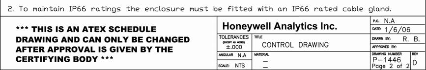
30 16 Control Drawing 29

31 30

32 17 Certification Label 31
44 943 4300 Fax: +41 (0)44 943 4398")
33 Find out more Contact Honeywell Analytics: Europe, Middle East, Africa, India Life Safety Distribution AG Wilstrasse 11-U31 CH-8610 Uster Switzerland Tel: +41 (0) Fax: +41 (0) Americas Honeywell Analytics Inc. 405 Barclay Blvd. Lincolnshire, IL USA Tel: Toll free: Fax: Asia Pacific Honeywell Analytics Asia Pacific #508, Kolon Science Valley (I) Guro-Dong, Guro-Gu Seoul, , Korea Tel: +82 (0) Fax: +82 (0) Technical Services Please Note: While every effort has been made to ensure accuracy in this publication, no responsibility can be accepted for errors or omissions. Data may change, as well as legislation, and you are strongly advised to obtain copies of the most recently issued regulations, standards, and guidelines. This publication is not intended to form the basis of a contract. Issue 3 10/2008 H_MAN0853_3002M5000_EMEAI 2008 Honeywell Analytics 12450
Technical Manual. LeakFilm Sensor. Film Type Liquid Leak Detection Sensor
 Technical Manual LeakFilm Sensor Film Type Liquid Leak Detection Sensor 1. Safety Ensure that this Operating Manual is read and understood BEFORE installing / operating / maintaining the equipment. Pay
Signalpoint. The Signalpoint range of flammable, toxic and Oxygen gas detectors offer users a low cost solution to their indoor gas monitoring needs
 Signalpoint The Signalpoint range of flammable, toxic and Oxygen gas detectors offer users a low cost solution to their indoor gas monitoring needs Signalpoint One-Stop Shop Flammable, toxic and Oxygen
Technical Manual. Series 3000 MkII Gas Detector
 Technical Manual Series 3000 MkII Gas Detector 1. Safety Ensure that this Operating Manual is read and understood BEFORE installing / operating / maintaining the equipment. Pay particular attention to
Sieger Sensepoint. Easy to Use Factory set operation Simple to replace Minimal training required
 Sieger Sensepoint The Sensepoint range of flammable, toxic and oxygen gas detectors offer users a high quality, low cost solution to their industrial gas monitoring needs. Sieger Sensepoint Fit For Purpose
Technical Manual. LeakFilm 5. 5 Channel Conductive Liquid Leak Detection Controller
 Technical Manual LeakFilm 5 5 Channel Conductive Liquid Leak Detection Controller 1. Safety Ensure that this Operating Manual is read and understood BEFORE installing / operating / maintaining the equipment.
Sensepoint. Fit For Purpose Flammable, toxic and oxygen versions available High performance, low cost Suitable for new and retro fit applications
 Sensepoint The Sensepoint range of flammable, toxic and oxygen gas detectors offer users a high quality, low cost solution to their industrial gas monitoring needs. Sensepoint Fit For Purpose Flammable,
Zareba Sensepoint Pro
 Zareba Sensepoint Pro Comprehensive monitoring of flammable, toxic and oxygen gas hazards in potentially explosive atmospheres Sensepoint Pro One-Stop Shop Flammable, toxic and oxygen versions available
Operating Instructions
 Operating Instructions Unipoint Flammable and Toxic Gas Detection Controller 1 Safety Ensure that this manual is read and understood BEFORE installing / operating / maintaining the equipment. WARNINGS
Sensepoint. Fit For Purpose Flammable, toxic and Oxygen versions available High performance, low cost Suitable for new and retro fit applications
 Sensepoint The Sensepoint range of flammable, toxic and Oxygen gas detectors offer users a high quality, low cost solution to their industrial gas monitoring needs. Sensepoint Fit For Purpose Flammable,
Instructions TXL Series Oxygen and Toxic Gas Detectors 4/
 Instructions 95-8541 TXL Series Oxygen and Toxic Gas Detectors Detector Electronics Corporation 6901 West 110th Street Minneapolis, Minnesota 55438 USA Tel: 952.941.5665 or 800.765.3473 Fax: 952.829.8750
TOXIC GAS AND OXYGEN DETECTOR DTX 420 INSTALLATION, OPERATING AND MAINTENANCE INSTRUCTIONS DTX420_MAN01_EN_V1R2
 TOXIC GAS AND OXYGEN DETECTOR INSTALLATION, OPERATING AND MAINTENANCE INSTRUCTIONS DTX420_MAN01_EN_V1R2 1 Introduction These instructions must be read carefully by any person who has or will have the responsibility
Safe Operation Manual. Honeywell IQ Force Gas Detector
 Safe Operation Manual Honeywell IQ Force Gas Detector Honeywell Analytics 800-663-4164 403-248-9226 Fax 403-575-3708 03JUN2012 P/N 50105843-047 Version 01 http://www.honeywell.com HONEYWELL IQ Force PERSONAL
Technical Manual. Sensepoint XCD Gas Detector PRE-LAUNCH
 Technical Manual Sensepoint XCD Gas Detector PRE-LAUNCH 1 Safety Ensure that this Operating Manual is read and understood BEFORE installing / operating / maintaining the equipment. Pay particular attention
RK Carbon Monoxide Transmitter Operator s Manual
 65-2335RK Carbon Monoxide Transmitter Operator s Manual Part Number: 71-0177RK Revision: 0 Released: 4/12/11 RKI Instruments, Inc. www.rkiinstruments.com WARNING Read and understand this instruction manual
CMF, CMX & CMA series
 Features Electrochemical sensor element 4-20 ma or 2-10 Vdc output CMF- IP 44 protection CMX- IP 54 protection CMA- IP 65 protection Wide supply voltage range (18-28 Vdc) Overload and short cicuit protected
TXgard-Plus. Flameproof Toxic and Oxygen Gas Detector with Non-intrusive One-man Calibration. Installation, Operation and Maintenance Instructions
 TXgard-Plus Flameproof Toxic and Oxygen Gas Detector with Non-intrusive One-man Calibration Installation, Operation and Maintenance Instructions M07194 Issue 5 March 2015 TXgard-Plus Introduction 1 Introduction
RK Carbon Monoxide Transmitter Operator s Manual
 65-2434RK Carbon Monoxide Transmitter Operator s Manual Part Number: 71-0061RK Edition: First, Revision C Released: December 2001 65-2434RK CO Transmitter 1 Product Warranty RKI Instruments, Inc., warranties
Sensepoint. The Sensepoint range of flammable, toxic and oxygen gas detectors offer users a low cost solution to their gas monitoring needs.
 Sensepoint The Sensepoint range of flammable, toxic and oxygen gas detectors offer users a low cost solution to their gas monitoring needs. Sensepoint One-Stop Shop Flammable, toxic and oxygen versions
RK Carbon Monoxide Transmitter Operator s Manual
 65-2432RK Carbon Monoxide Transmitter Operator s Manual Part Number: 71-0070RK Revision: P1 Released: July 8, 2001 RKI Instruments, Inc. 1855 Whipple Road Hayward CA 94544 Phone: 800-754-5165 Fax: 510-441-5650
User Manual. PolyGard CO LC-1112 V3. Electrochemical analog carbon monoxide transmitters serial no. EC-S 002. August 29, 2006
 PolyGard CO LC-1112 V3 Electrochemical analog carbon monoxide transmitters serial no. EC-S 002 User Manual August 29, 2006 January 04, 2016 Revision Specifications subject to change without notice. USA
Touchpoint 1. The Touchpoint 1 controller provides 24 hour protection from flammable, toxic or Oxygen gas hazards.
 Touchpoint 1 The Touchpoint 1 controller provides 24 hour protection from flammable, toxic or Oxygen gas hazards. Touchpoint 1 controller User Friendly Self-contained, wall mounted enclosure Ultra-clear
GASGUARD Cl 2. Chlorine Sensor OPERATING & INSTALLATION MANUAL
 GASGUARD Cl 2 Chlorine Sensor OPERATING & INSTALLATION MANUAL Operating and Installation Manual 2 Table of Contents GasGuard Cl 2 Operating and Instruction Manual General description. 4 Installation..
Carbon Dioxide Sample-Draw Detector Operator s Manual
 35-3001-05-03 Carbon Dioxide Sample-Draw Detector Operator s Manual Part Number: 71-0413 Revision: 0 Released: 8/4/17 www.rkiinstruments.com WARNING Read and understand this instruction manual before operating
RK/ RK Carbon Monoxide Detector Operator s Manual
 65-2496RK/65-2499RK Carbon Monoxide Detector Operator s Manual Part Number: 71-0156RK Revision: 0 Released: 2/16/11 www.rkiinstruments.com WARNING Read and understand this instruction manual before operating
Intrinsically Safe, NEMA 4, Type 4X, IP67 Loop-Powered Meter
 PD685 Intrinsically Safe, NEMA 4, Type 4X, IP67 Loop-Powered Meter Actual Size Digits C US Intrinsically Safe 3½ Digits LARGE DISPLAY NEMA 4, Type 4X, IP67 Loop-Powered Field-Mount Process Meter 4-20 ma
GG-CO-EXP CARBON MONOXIDE SENSOR. Installation and Operation Manual
 GG-CO-EXP CARBON MONOXIDE SENSOR Installation and Operation Manual 2 GG-CO-EXP Warning Use this product only in the manner described in this manual. If the equipment is used in a manner not specified by
OLCT 10N. Digital Gas Detector. User Manual. The Fixed Gas Detection Experts. Part Number: NPO10NEN Version: G.1
 User Manual OLCT 10N Digital Gas Detector Part Number: NPO10NEN Version: G.1 The Fixed Gas Detection Experts Copyright 2015 by OLDHAM S.A.S May 2015 All rights reserved. No reproduction of all or part
CT-7 Series Toxic Gas Transmitter Operator s Manual
 65-2341 CT-7 Series Toxic Gas Transmitter Operator s Manual Part Number: 71-0424 Revision: P1 Released: 6/8/17 RKI Instruments, Inc. www.rkiinstruments.com WARNING Read and understand this instruction
GASGUARD H 2-1% Hydrogen Sensor OPERATING & INSTALLATION MANUAL
 GASGUARD H 2-1% Hydrogen Sensor OPERATING & INSTALLATION MANUAL 2 Table of Contents GasGuard H 2-1% General description. 4 Installation.. 4 Locating the sensor. 4 Installation guidelines 5 Wiring.. 6 Operation..
Macurco Single-Gas XL Series Monitor, CM-1XL Carbon Monoxide (CO), HS-1XL Hydrogen Sulfide (H2S) User Instructions
, HS-1XL Hydrogen Sulfide (H2S) User Instructions") Macurco Single-Gas XL Series Monitor, CM-1XL Carbon Monoxide (CO), HS-1XL Hydrogen Sulfide (H2S) User Instructions Important: Keep these User Instructions for reference 2 TABLE OF CONTENTS GENERAL SAFETY
Macurco Single-Gas XL Series Monitor, CM-1XL Carbon Monoxide (CO), HS-1XL Hydrogen Sulfide (H2S) User Instructions Important: Keep these User Instructions for reference 2 TABLE OF CONTENTS GENERAL SAFETY
Software Version 2.01 LEVEL MONITOR MODEL 220
 Software Version 2.01 LEVEL MONITOR MODEL 220 19 April 2000 CONTENTS 1. Introduction 1 1.1 Model Number Designation 2 1.2 Intrinsic Safety Considerations 3 2. Specification 4 3. Operation 6 3.1 Display
GG-H2S HYDROGEN SULFIDE GAS SENSOR. Installation and Operation Manual
 GG-H2S HYDROGEN SULFIDE GAS SENSOR Installation and Operation Manual 2 GG-H2S Warning Use this product only in the manner described in this manual. If the equipment is used in a manner not specified by
RK CO 2 Transmitter Operator s Manual
 65-2397RK CO 2 Transmitter Operator s Manual Part Number: 71-0185RK Revision: B Released: 7/18/14 RKI Instruments, Inc. www.rkiinstruments.com WARNING Read and understand this instruction manual before
Operating Instructions
 Operating Instructions Sieger Type 705 CO Sensor and Transmitter for Electrochemical Cells UL Certified 00705A1731 HELPING TO MAKE A SAFER WORLD Ensure that you read and understand these Operating Instructions
Sensepoint XCD RTD (Remote Toxic Detector) Technical Manual
 Technical Manual") Technical Manual Sensepoint XCD RTD (Remote Toxic Detector) Technical Manual 1 Safety Ensure that this Technical Manual is read and understood BEFORE installing / operating / maintaining the equipment.
Technical Manual Sensepoint XCD RTD (Remote Toxic Detector) Technical Manual 1 Safety Ensure that this Technical Manual is read and understood BEFORE installing / operating / maintaining the equipment.
GASGUARD NH 3. Ammonia Sensor OPERATING & INSTALLATION MANUAL
 GASGUARD NH 3 Ammonia Sensor OPERATING & INSTALLATION MANUAL Operating and Installation Manual 2 Table of Contents GasGuard NH 3 Operating and Instruction Manual General description. 4 Installation.. 4
Series 3000 XPIS. 2-wire loop powered toxic and Oxygen gas detector for use in potentially explosive atmospheres
 Series 3000 XPIS -wire loop powered toxic and Oxygen gas detector for use in potentially explosive atmospheres Series 3000 XPIS Reliable detection Proven electrochemical sensing technology Uses Surecell
Sieger Apex. Flexibility that meets your requirements
 Sieger Apex Flexibility that meets your requirements Sieger Apex Easy to Install Sensor can be remotely mounted up to 100m from the transmitter On board relays allow for local audible/ visual alarms Strong
GASGUARD H2S EXP. Hydrogen Sulfide Sensor OPERATING & INSTALLATION MANUAL
 GASGUARD H2S EXP Hydrogen Sulfide Sensor OPERATING & INSTALLATION MANUAL Operating and Installation Manual Warning Use this product only in the manner described in this manual. If the equipment is used
GG-NH3 AMMONIA GAS SENSOR. Installation and Operation Manual
 GG-NH3 AMMONIA GAS SENSOR Installation and Operation Manual 2 GG-NH3 Warning Use this product only in the manner described in this manual. If the equipment is used in a manner not specified by Calibration
DL424/425 DirectLine Sensor Module for Dissolved Oxygen Probes Series DL5000 Specifications
 DL424/425 DirectLine Sensor Module for Dissolved Oxygen Probes Series DL5000 Specifications 70-82-03-48 January 2003 Overview The DirectLine DL424/425 Sensor Modules are part of a family of products developed
ALTAIR 5X Multigas Detector Product Specification
 ALTAIR 5X Multigas Detector Product Specification PHYSICAL CHARACTERISTICS Gas delivery Size, pumped unit without IR Size, pumped unit with IR Weight Handling Case material Environmental protection Display
RK/ RK Oxygen Detector Operator s Manual
 65-2494RK/65-2497RK Oxygen Detector Operator s Manual Part Number: 71-0179RK Revision: 0 Released: 2/16/11 www.rkiinstruments.com WARNING Read and understand this instruction manual before operating detector.
RK-02 Multi Point Detector Operator s Manual
 65-2485RK-02 Multi Point Detector Operator s Manual Part Number: 71-0237RK Revision: A Released: 11/26/14 RKI Instruments, Inc. www.rkiinstruments.com WARNING Read and understand this instruction manual
RK-05 Carbon Monoxide Detector Operator s Manual
 65-2433RK-05 Carbon Monoxide Detector Operator s Manual Part Number: 71-0189RK Revision: 0 Released: 5/17/11 RKI Instruments, Inc. www.rkiinstruments.com WARNING Read and understand this instruction manual
GASGUARD NH 3 2% Ammonia Sensor OPERATING & INSTALLATION MANUAL
 GASGUARD NH 3 2% Ammonia Sensor OPERATING & INSTALLATION MANUAL 2 Table of Contents GasGuard NH 3 2% General description. 4 Installation.. 4 Locating the sensor. 4 Installation guidelines 5 Wiring.. 6
GASGUARD VENT LINE3. Ammonia Sensor OPERATING & INSTALLATION MANUAL
 GASGUARD VENT LINE3 Ammonia Sensor OPERATING & INSTALLATION MANUAL Operating and Installation Manual Warning Use this product only in the manner described in this manual. If the equipment is used in a
GG-VL-R REFRIGERANT VENT LINE SENSOR. Installation and Operation Manual
 GG-VL-R REFRIGERANT VENT LINE SENSOR Installation and Operation Manual 2 GG-VL-R Warning Use this product only in the manner described in this manual. If the equipment is used in a manner not specified
GG-NO2 NITROGEN DIOXIDE GAS SENSOR. Installation and Operation Manual
 GG-NO2 NITROGEN DIOXIDE GAS SENSOR Installation and Operation Manual 2 GG-NO2 Warning Use this product only in the manner described in this manual. If the equipment is used in a manner not specified by
P R O D U C T S P E C I F I C A T I O N MSA Ultima X Series Sensor/Transmitter Specification
 P R O D U C T S P E C I F I C A T I O N MSA Ultima X Series Sensor/Transmitter Specification 1.0 This specification details the attributes and operating characteristics of the MSA Ultima X Series sensors/transmitters.
Operating Instructions
 Operating Instructions Sensepoint / Signalpoint Bridge to 4 20mA Converter TOTAL ENVIRONMENTAL SOLUTIONS Ensure that you read and understand these instructions BEFORE operating the equipment. Please pay
GG-NH3-2% AMMONIA GAS SENSOR. Installation and Operation Manual
 GG-NH3-2% AMMONIA GAS SENSOR Installation and Operation Manual 2 GG-NH3-2% Warning Use this product only in the manner described in this manual. If the equipment is used in a manner not specified by Calibration
DB5 Intrinsically Safe Sounder Type DB-5
 Operating Instructions RTK Instruments Limited DB5 Intrinsically Safe Sounder Type DB-5 Description The DB5 Sounder is a strong, lightweight warning sounder, CENELEC certified to Ex II 1G EExia IIC T4
RK-05 Carbon Monoxide Transmitter Operator s Manual
 65-2432RK-05 Carbon Monoxide Transmitter Operator s Manual Part Number: 71-0113RK Revision: B Released: 11/26/14 www.rkiinstruments.com WARNING Read and understand this instruction manual before operating
GASGUARD LEL 3 OPERATING & INSTALLATION MANUAL
 GASGUARD LEL 3 Ammonia Sensor OPERATING & INSTALLATION MANUAL GasGuard LEL 3 Operating and Installation Manual 2 Table of Contents 3GasGuard LEL Operating and Instruction Manual General description. 4
4-20mA CYBER Cyber Transmitter for flammable, toxic and IR gas detection Cyber Head Increased security in ATEX certified head
 4-20mA CYBER Cyber Transmitter for flammable, toxic and IR gas detection Cyber Head Increased security in ATEX certified head NET DRAFT version 2.1-2008 Pag. 1 4-20mA Cyber - DRAFT version 2.1-2008 Pag.
Zareba Metro Gas Detector
 Zareba Metro Gas Detector The Metro addressable gas detector enables remote monitoring of flammable and toxic gas hazards Metro Gas Detector One-Stop Shop Flammable and toxic gas monitors available Methane,
GASGUARD SO2 Sulfur Dioxide Sensor OPERATING & INSTALLATION MANUAL
 GASGUARD SO2 Sulfur Dioxide Sensor OPERATING & INSTALLATION MANUAL Operating and Installation Manual Warning Use this product only in the manner described in this manual. If the equipment is used in a
Touchpoint 4. The Touchpoint 4 controller provides protection of personnel and plant from flammable, toxic and Oxygen gas hazards
 Touchpoint 4 The Touchpoint 4 controller provides protection of personnel and plant from flammable, toxic and Oxygen gas hazards Touchpoint 4 Controller User Friendly Self-contained, wall mounted enclosure
GASGUARD O 2. Oxygen Sensor OPERATING & INSTALLATION MANUAL
 GASGUARD O 2 Oxygen Sensor OPERATING & INSTALLATION MANUAL 2 Table of Contents General description. 4 Installation.. 4 Locating the sensor. 4 Installation guidelines 5 Wiring.. 6 Operation.. 7 Start-up...
RK Combustible Gas Transmitter Operator s Manual
 65-2400RK Combustible Gas Transmitter Operator s Manual Part Number: 71-0060RK Revision: C Released: 1/31/13 www.rkiinstruments.com WARNING Read and understand this instruction manual before operating
Beacon 800 Gas Monitor Operator s Manual
 Beacon 800 Gas Monitor Operator s Manual Part Number: 71-0037RK Revision: F Released: 4/18/17 www.rkiinstruments.com Product Warranty RKI Instruments, Inc. warrants gas alarm equipment sold by us to be
Quick Start Guide. XNX Universal Transmitter
 Quick Start Guide XNX Universal Transmitter Table of Contents 1 Introduction...5 2 Warnings...6 3 Mounting and Location of Detectors...8 3.1 Mounting the XNX Universal Transmitter...8 4 Wiring the XNX
RK-05 Combustible Gas Transmitter Operator s Manual
 65-2405RK-05 Combustible Gas Transmitter Operator s Manual Part Number: 71-0180RK Revision: 0 Released: 2/16/11 RKI Instruments, Inc. www.rkiinstruments.com WARNING Read and understand this instruction
5 Operating Modes GX Smallest 6 gas sample draw PID library of over 600 VOC s 2 Interchangable smart sensor slots
 5 Operating Modes GX-6000 Smallest 6 gas sample draw PID library of over 600 VOC s 2 Interchangable smart sensor slots CONFINED SPACE ENTRY Monitor LEL, O2, CO, and H2S Internal sample pump Pull samples
GG-EM ENTRANCE MONITOR. Installation and Operation Manual
 GG-EM ENTRANCE MONITOR Installation and Operation Manual 2 GG-EM Warning Use this product only in the manner described in this manual. If the equipment is used in a manner not specified by Calibration
RK Hydrogen Sulfide Transmitter Operator s Manual
 65-2331RK Hydrogen Sulfide Transmitter Operator s Manual Part Number: 71-0176RK Revision: B Released: 11/26/14 RKI Instruments, Inc. www.rkiinstruments.com WARNING Read and understand this instruction
Technical Manual. LeakFilm Pro. Single Channel Conductive and Chemical Liquid Leak Detection Controller with Leak Location Detection
 Technical Manual LeakFilm Pro Single Channel Conductive and Chemical Liquid Leak Detection Controller with Leak Location Detection 1. Safety Ensure that this Operating Manual is read and understood BEFORE
Combustible Gas Sample-Draw Detector Operator s Manual
 35-3001-01 Combustible Gas Sample-Draw Detector Operator s Manual Part Number: 71-0282RK Revision: A Released: 8/3/17 www.rkiinstruments.com WARNING Read and understand this instruction manual before operating
GLD-30 Gas Leak Detector
 GLD-30 Gas Leak Detector Installation, Operation & Maintenance General: The Archer Instruments GLD-30 is an ambient air monitor, used to detect the presence of a target gas (or gases) and to alert operators
FREEDOM SERIES 5000 AND 5600 GAS TRANSMITTERS
 FREEDOM SERIES 5000 AND 5600 GAS TRANSMITTERS FREEDOM SERIES 5000 & 5600 MAKING INSTALLATION AND EVERYDAY OPERATION EASY The Freedom Series 5000 and 5600 are full-featured 4-20mA, loop powered transmitters
5 Operating Modes GX Smallest 6 gas sample draw PID library of over 600 VOC s 2 Interchangable smart sensor slots
 5 Operating Modes GX-6000 Smallest 6 gas sample draw PID library of over 600 VOC s 2 Interchangable smart sensor slots GX-6000 5 Operating modes Normal Leak Check Inert Bar hole Snap Log Monitor up to
Carbon Monoxide Sample-Draw Detector Operator s Manual
 35-3001-04-01 Carbon Monoxide Sample-Draw Detector Operator s Manual Part Number: 71-0395 Revision: 0 Released: 8/4/17 www.rkiinstruments.com WARNING Read and understand this instruction manual before
Technical Manual. Sensepoint XCD Gas Detector
 Technical Manual Sensepoint XCD Gas Detector 1 Safety Ensure that this Technical Manual is read and understood BEFORE installing / operating / maintaining the equipment. Pay particular attention to Warnings
SIL 2. Ultima X Series Gas Monitors CERTIFIED
 Ultima X Series Gas Monitors 5 Now with SIL 2 CERTIFIED Products Versatile fixed instruments provide continuous monitoring of many hazardous gases using catalytic, electrochemical, and infrared gas detection
M2A Transmitter Operator s Manual
 M2A Transmitter Operator s Manual Part Number: 71-0305RK Revision: F Released: 1/8/18 RKI Instruments, Inc. www.rkiinstruments.com WARNING Read and understand this instruction manual before operating instrument.
Carbon Monoxide Transmitter
 Introduction The CO Transmitter uses an electrochemical sensor to monitor the carbon monoxide level and outputs a field-selectable 4-20 ma or voltage signal. The voltage signal may also be set to 0-5 or
RK/ RK Oxygen Detector Operator s Manual
 65-2502RK/65-2510RK Oxygen Detector Operator s Manual Part Number: 71-0074RK Revision: A Released: 3/1/11 www.rkiinstruments.com WARNING Read and understand this instruction manual before operating detector.
Two-Channel Gas Controller
 Two-Channel Gas Controller Specifications subject to change without notice. USA 09 Page of DESCRIPTION Highly configurable, UL 0 performance-tested and -certified, and wall-mounted gas monitor; continuously
ULTIMA XL/XT Series Gas Monitors. [ Ultimate Features Extreme Design ]
![ULTIMA XL/XT Series Gas Monitors. [ Ultimate Features Extreme Design ]](/thumbs/81/83177381.jpg "ULTIMA XL/XT Series Gas Monitors. [ Ultimate Features Extreme Design ]") ULTIMA XL/XT Series Gas Monitors [ Ultimate Features Extreme Design ] Cost effective fixed installation gas monitors with HART Field Communications Protocol. Single-sensor units use catalytic, electrochemical
ULTIMA XL/XT Series Gas Monitors [ Ultimate Features Extreme Design ] Cost effective fixed installation gas monitors with HART Field Communications Protocol. Single-sensor units use catalytic, electrochemical
5New features & EXtreme design, now with HART Protocol and DuraSource Technology. Ultima X Series Gas Monitors
 Ultima X Series Gas Monitors Versatile fixed instruments provide continuous monitoring of many hazardous gases using catalytic, electrochemical, and infrared gas detection methods. HART Protocol is now
ToxiRAE II. PGM-1100 Series Personal Toxic Gas Monitor. User Manual
 ToxiRAE II PGM-1100 Series Personal Toxic Gas Monitor User Manual 045-4003-000, Revision B, March 2005 - READ BEFORE OPERATING - This manual must be carefully read by all individuals who have or will have
Technical Manual. Zareba Sensepoint Gas Detectors
 Technical Manual Zareba Sensepoint Gas Detectors 2 Safety Ensure that this Technical Manual is read and understand BEFORE installing/operating/maintaining the equipment. Pay particular attention to Warnings
GasScanner 8C. Eight Channel Monitor. Operator s Manual. MINT-0281-XX Rev. A 01/29/08
 GasScanner 8C Eight Channel Monitor Operator s Manual MINT-0281-XX Rev. A 01/29/08 Product Warranty Matheson Tri-Gas, Inc., warrants gas alarm equipment sold by us to be free from defects in materials,
MODEL GT812 NOVA-SENSOR ELITE TOXIC GAS DETECTOR
 DESIGN MANUAL INSTALLATION -- OPERATION -- MAINTENANCE SERVICE MANUAL MODEL GT812 NOVA-SENSOR ELITE TOXIC GAS DETECTOR 70099 The information and technical data disclosed by this document may be used and
Xgard. Fixed detectors For flammable, toxic or oxygen gases
 Fixed detectors For flammable, toxic or oxygen gases Xgard Xgard Type 1: Xgard Type 2: Xgard Type 3: Xgard Type 4: Xgard Type 5: Xgard Type 6: Xsafe: Intrinsically safe toxic and oxygen gas detector Flameproof
RK Multi Point Detector Operator s Manual
 65-2480RK Multi Point Detector Operator s Manual Part Number: 71-0198RK Revision: C Released: 11/26/14 RKI Instruments, Inc. www.rkiinstruments.com WARNING Read and understand this instruction manual before
FX-SMT Series INSTRUCTION MANUAL P/N THERMO ELECTRON CORPORATION ENVIRONMENTAL INSTRUMENTS 27 FORGE PARKWAY FRANKLIN MASSACHUSETTS 02038
 FX-SMT Series INSTRUCTION MANUAL P/N 71-0085 THERMO ELECTRON CORPORATION ENVIRONMENTAL INSTRUMENTS 27 FORGE PARKWAY FRANKLIN MASSACHUSETTS 02038 (866) 282-0430 Toll Free (508) 520-0430 International (508)
SPECIFICATION MODEL 5200 GAS MONITOR SYSTEM. User Instructions For The Model 5200 Gas Monitor System
 SPECIFICATION MODEL 5200 GAS MONITOR SYSTEM User Instructions For The Model 5200 Gas Monitor System To completely customize the specifications to your exact application, modifications to the following
DESIGN MANUAL MODEL GIR900 INFRARED COMBUSTIBLE GAS SENSOR
 DESIGN MANUAL MODEL GIR900 INFRARED COMBUSTIBLE GAS SENSOR 70086 The information in this doucment is applicable to sensors built in September, 2008 or later (Firmware 3.0) The information and technical
REMOTE TOXIC, COMBUSTIBLE, AND OXYGEN GAS SENSORS
 REMOTE TOXIC, COMBUSTIBLE, AND OXYGEN GAS SENSORS FEATURES Extremely wide range of sensors Easy installation and maintenance Low cost of ownership Replacement of sensors are simple Rugged and reliable
GG-LEL2 COMBUSTIBLE GAS SENSOR. Installation and Operation Manual
 GG-LEL2 COMBUSTIBLE GAS SENSOR Installation and Operation Manual 2 GG-LEL2 Warning Use this product only in the manner described in this manual. If the equipment is used in a manner not specified by Calibration
AT-G-DETECT Gas Sensing System
 AT-G-DETECT Gas Sensing System CHECK / CALIBRATION PROCEDURE* *Technician use only This procedure must be carried out by a suitably qualified technician in accordance with these instructions and the standards
GG-R REFRIGERANT SENSOR. Installation and Operation Manual
 GG-R REFRIGERANT SENSOR Installation and Operation Manual 2 GG-R Warning Use this product only in the manner described in this manual. If the equipment is used in a manner not specified by Calibration
Operating Instructions
 1. Safety Warnings and Information 1 Safety Warnings and Information WARNINGS 1. Installation must be in accordance with the recognized standards of the appropriate authority in the country concerned.
REMOTE TOXIC, COMBUSTIBLE, AND OXYGEN GAS SENSORS WITH LOCAL DIGITAL DISPLAY
 REMOTE TOXIC, COMBUSTIBLE, AND OXYGEN GAS SENSORS WITH LOCAL DIGITAL DISPLAY FEATURES TXGARD & FLAMGARD PLUS Digital display with flexible output options Wide range of long life sensors Non-intrusive one-man
MODEL: O ELECTROCHEMICAL O2 DETECTOR (Used with ST1400 O2 Sensor) Part Number: MAN Rev. 0
 Part Number: MAN Rev. 0") MODEL: O2-25-24 ASSEMBLY CONSISTS OF: XP-O2 housing (supersedes PE-EX-O2) ST1400-500-24 sensor (supersedes PE1400-500-24) JB2 junction box CB2 connector board ELECTROCHEMICAL O2 DETECTOR (Used with ST1400
MODEL: O2-25-24 ASSEMBLY CONSISTS OF: XP-O2 housing (supersedes PE-EX-O2) ST1400-500-24 sensor (supersedes PE1400-500-24) JB2 junction box CB2 connector board ELECTROCHEMICAL O2 DETECTOR (Used with ST1400
Combustible Gas/Hydrogen Sulfide Sample-Draw Detector Operator s Manual
 35-3001-07 Combustible Gas/Hydrogen Sulfide Sample-Draw Detector Operator s Manual Part Number: 71-0411 Revision: 0 Released: 8/7/17 www.rkiinstruments.com WARNING Read and understand this instruction
RK Transmitter Technical Notice
 65-2450RK Transmitter Technical Notice Although this Operator s Manual was written for the 65-2400RK combustible gas LEL transmitter, the operational instructions are the same for the 65-2450RK hydrogen