Consultation Draft. Issue 2. Good Practice Guide No. 29. The Examination, Testing and Calibration of Installed Radiation Protection Instruments
|
|
|
- Lindsey Simpson
- 6 years ago
- Views:
Transcription
1 Good Practice Guide No. 29 The Examination, Testing and Calibration of Installed Radiation Protection Instruments Peter Burgess, Lynsey Keightley, Clare Lee, Max Pottinger, Mike Renouf, David Williams. Consultation Draft Issue 2
2 CONSULTATION DRAFT The Examination, Testing and Calibration of Installed Radiation Protection Instruments This document has been prepared by a working group of the Ionising Radiation Metrology Forum. It is intended to form the second edition of the established NPL Guide GPG29. The working group invite you to comment on the technical content of this document before publication. If you wish to submit comments, please send them to lynsey.keightley@npl.co.uk by 17 February Lynsey Keightley National Physical Laboratory Tel
3 The Examination, Testing and Calibration of Installed Radiation Protection Instruments Peter Burgess Nuvia Lynsey Keightley National Physical Laboratory Clare Lee National Physical Laboratory Max Pottinger James Fisher Nuclear Mike Renouf Sellafield Ltd David Williams Magnox Ltd ii
4 Queen s Copyright Printer and Controller of HMSO, 2011 ISSN XXXX-XXXX National Physical Laboratory Hampton Road, Teddington, Middlesex, TW11 0LW Extracts from this report may be reproduced provided the source is acknowledged and the extract is not taken out of context. Approved on behalf of the Managing Director, NPL by XXXX iii
5 This Good Practice Guide has been written by a working party of the Ionising Radiation Metrology Forum. Membership of the working party was as follows: Working Group Peter Burgess Lynsey Keightley Clare Lee Max Pottinger Mike Renouf David Williams Nuvia National Physical Laboratory National Physical Laboratory James Fisher Nuclear Sellafield Ltd Magnox Ltd iv
6 Foreword This Good Practice Guide has been written by the UK Ionising Radiation Metrology Forum 1 in collaboration with the radiation user community. It describes recommended procedures for the examination, testing and calibration of installed radiation protection instruments. Test procedures recommended in this document are not legally binding: they are general methods based on current accepted good practice. The current statutory requirement for installed radiation protection instrument tests is stated in the Ionising Radiations Regulations 1999, Regulation 19. All Employers who work with ionising radiation must ensure that levels are adequately monitored and instruments are suitable for this purpose. Although the testing regimes presented here are for general application, Qualified Persons responsible for the calibration of radiation protection instruments may modify them, with the agreement of the Radiation Protection Adviser, as necessary to suit their particular purpose, provided that the Employer is satisfied that the overall quality of the testing is not compromised. 1 The Ionising Radiation Metrology Forum consists of representatives of UK establishments and organisations actively involved in radiation measurement for protection purposes. It is the aim of the forum to facilitate the exchange of information regarding UK calibration facilities and their efficient use by those required to comply with these regulations. v
7 CONTENTS Foreword 2.1 Type Tests Tests Before First Use Periodic Tests Routine Tests Retest After Repair Analysis of Test Results Gamma Dose Rate Monitors Personnel Contamination Monitors Hand and Foot Monitors Frisking Monitors Personnel Exit Monitors Portal Monitors Small Article Monitors Functional Check Background Indication Alarm Test Operational High Level Alarm Detector Fail Alarm Response to High Dose Rates Linearity of Response Energy Dependence of Gamma Monitors Directional Dependence Functional Check Energy Threshold Check Background Indication Response to Contamination Count Rate Alarm Test Response to a High Activity Source Uniformity of Response Functional Check vi
8 6.2 Energy Threshold Check Background Indication Count Rate Alarm Test Response to Contamination Response to High Activity Source Uniformity of Response Functional Check Energy Threshold Check Background Indication Count Rate Alarm Test Response to Contamination Linearity of Response Response to High Activity Source Spatial Response Source Considerations and Jigs Workplace Contamination Monitors Workplace SAMS... Error! Bookmark not defined. 8.4 Workplace Portals... Error! Bookmark not defined. 9.1 Calibration Laboratory... Error! Bookmark not defined. 9.2 Workplace Testing... Error! Bookmark not defined. 9.3 Test Label... Error! Bookmark not defined. vii
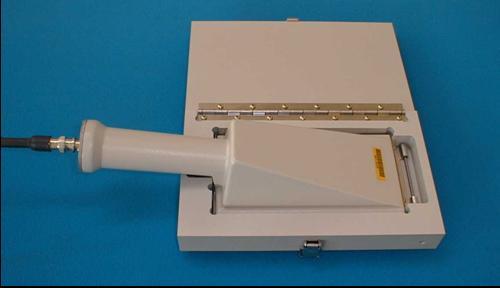
9 TABLES Table 1: Summary of Tests Before First Use and Periodic Tests Table 2: Tests Required for Gamma Dose Rate Monitors Table 3: Tests Required fro Personnel Contamination Monitors Table 4: Tests Required for Portal Monitors Table 5: Tests Required for Small Articles Monitors Table 6: List of Suitable Check Radionuclides ILLUSTRATIONS Figure 1: Testing Regimes for Installed Instruments... 7 Figure 2: Hand Contamination Monitor Calibration Source Figure 3: Frisking Contamination Monitor Calibration Jig Figure 4: Exit Contamination Monitor Calibration Jig (Ladder) Figure 5: Typical Steel Walled Energy Compensated GM Detector Figure 6: Pancake GM Detector viii
10 Introduction 1 IN THIS CHAPTER Introduction 1
11 The examination and testing of radiation protection instruments is a legal requirement for those carrying out work with ionising radiations 1, 2. Sufficient equipment must be available to comply with the regulations and the instruments must be examined, tested and calibrated at appropriate intervals to ensure that they remain fit for use. Periodic examination and testing of installed equipment would normally take place in the workplace. This minimises risk of damage caused by removal, transport and reinstallation of equipment: it also permits testing of auxiliary indicators, such as remote warning lights. This Good Practice Guide provides recommended procedures for the general examination, testing and calibration of installed radiation protection instruments. The primary purpose of such equipment is protection of personnel and includes personnel exit monitors and frisking equipment, portal monitors, Small Articles Monitors (SAMS) and area gamma monitors. The scope of this document does not extend to equipment used for the monitoring of airborne radioactive particulates, this guidance is provided in GPG82 3, nor does it extend to installed environmental protection instruments. Additionally, this document does not provide guidance associated with the maintenance and examination of engineering controls. This guidance follows a similar format to GPG14 4, which provides advice for portable radiation protection instruments. Recommendations made in documents published by national and international organisations, including the United Kingdom Accreditation Service (UKAS), the International Organisation for Standardisation (ISO), the International Electrotechnical Commission (IEC) and International Atomic Energy Agency (IAEA) 5 have been consulted during the preparation of this Guide. The objective of testing is to demonstrate that the instrument is suitable and fit for use. The testing regimes contained herein have no legal standing and Employers may implement their own schemes, provided they ensure compliance with the relevant regulations. The procedures detailed in this guidance provide the minimum level of testing that is recommended for instruments used in normal operating conditions. There may be special cases where testing requirements will go beyond these recommendations, where instruments are used in conditions outside those envisaged in the standards above. In such circumstances, the Employer may need to design appropriate test procedures. Due to the varied nature of the instruments covered in the Guide and their applications, it is not always possible to specify complete calibration geometries and suitable radionuclides. In these instances it is the responsibility of the Qualified Person, in conjunction with the Radiation Protection Advisor, to define suitable test 2
12 protocols to be employed for each instrument type to suit the application for which it is used and the environment in which it operates. A glossary of terms is contained in Section 11. The types of instrument that are covered by this guidance are described in detail in Section 3. 3
13 Testing Regime 2 IN THIS CHAPTER Type Tests Tests Before First Use Periodic Tests Routine Tests Retest After Repair Analysis of Test Results 4
14 For the purposes of this guidance, a test is defined as a procedure to evaluate an instrument s performance in order to establish its suitability, or its continued fitness, for a particular type(s) of measurement in operational radiation protection. A test will involve an element of calibration, which may be defined as the measurement of the response of the instrument to known radiation fields. It is important to recognise that the terms test and calibration are not synonymous: this is because a test will also involve a degree of examination, which may include, for example, an inspection of the mechanical and electrical state of the instrument. Type Tests are laboratory tests that establish and confirm an instrument s specification. The Type Tests are normally carried out by, or on behalf of, the instrument manufacturer. Manufacturer s Production Tests confirm a tolerance in production, confirming that each instrument conforms to type and so meets specification. These tests may be considered as factory acceptance tests (FAT) by an employer but they must be undertaken by or under the direct supervision of a Qualified Person on behalf of the Employer if they are intended to satisfy Test Before First Use requirements. The tests required for compliance with current regulations are the Tests Before First Use (TBFU) and Periodic Tests. The findings of these tests must be compared with any previous test information and the appropriate Type Test to confirm that the instrument is meeting its specification and is suitable for its intended use. TBFU and Periodic Tests are carried out by, or on behalf of, the Employer. Table 1 lists recommended TBFU and Periodic Tests. Commissioning of an instrument may well include TBFU and/or establishing the Baseline for subsequent Periodic Tests. Commissioning may also include the testing of interfaces between instruments and their remote displays or safety or warning devices. Routine Tests and function checks are also recommended. A Routine Test includes testing an instrument s response to traceable sources, e.g. alarm level testing. A function check is a simple test carried out to ensure that the instrument appears to be working correctly - it does not necessarily require the use of a radioactive source. For gamma monitors it may include observation of response to any local radiation field and/or any detector priming source. For contamination monitors a function check is usually carried out together with routine maintenance such as detector cleaning, checking foils, etc. Further details on recommended function checks can be found in Sections 4 to 7. 5
15 A Test after repair is required to ensure that instrument performance has been reestablished after repair. Depending on the nature of the repair, the scope of Test after repair may be anything from function checks through to a new TBFU to provide a new Periodic Test baseline. All tests should be traceable and repeatable. A full record of test results, including details of any significant adjustments made to the instrument, should be kept for a minimum period of 2 years. A summary of these tests and checks is shown in Figure 1 identifying the different ways TBFU can be achieved in practice. The diagram is intended to show a variety of possible routines but is not considered to be exhaustive. 6
16 Test Before First Use in employer's workshop after transport Periodic Test Baseline Install Commission Routine Test (to validate baseline) Test after repair Type Test (in laboratory) Factory Acceptance Test Test Before First Use at manufacturer's premises Test Before First Use at a test house Transport Install Commission Periodic Test Baseline Routine Test Test after repair Manufacturer's responsibility/accountability Employer's responsibility/accountability Test Before First Use after transport and installation Measurement Good Practice Guide No. 29 7
17 It is the responsibility of the Employer to ensure that an instrument is suitable for the intended use before purchase. Decisions about instrument selection should be made taking into account advice from an RPA, information from the manufacturer and other authoritative data that might be available. The body of information regarding the characteristics and expected performance of instruments is called Type Test data and is usually based on recommendations from international organisations such as IEC, ISO, etc. A number of IEC documents exist which detail the tests that are appropriate for the Type Testing of particular types of instrument. Typical documents for testing installed instrumentation are BS IEC for X- and gamma-ray dose rate monitors and BS EN for installed contamination monitors and portal monitors. Although no standard fully addresses contamination frisking monitors, parts of BS EN , the standard for portable contamination monitors, may also be applied to this type of equipment. Currently there is no standard covering SAMs. Type Tests are very comprehensive and may require specialised facilities: the tests should be performed by someone with appropriate expertise and insight into the use of instruments, in a laboratory with secondary standard or similar status, using International Commission on Radiation Units and Measurements 9 specified measurement quantities, ISO specified calibration sources and ISO specified radiation beams. For most new instruments, the manufacturers or suppliers provide Type Test data that will enable the Employer to decide the necessary scope of TBFU. In the absence of Type Test data, other sources of information, for example, published peer reviewed evaluations, may be useful. When Type Test data are not available, or are insufficient in the judgement of the QP and RPA, the Employer should perform their own Type Test to establish their own baseline data at the TBFU stage. Assuming that the instrument is delivered in good condition and set up according to its specifications, the TBFU should demonstrate that the instrument conforms to type and confirm its suitability for the intended use. The practicalities of TBFU are dependent on whether an instrument is installed before or after TBFU. A gamma monitor, frisk probe and ratemeter or a hand and foot monitor can be tested before installation but this may be impractical for a large installed personnel exit monitor. 8
18 The TBFU should be undertaken by a Test House on behalf of the Employer. Tests must be undertaken by or under the immediate supervision of a Qualified Person on behalf of the Employer. Figure 1 illustrates the stages at which the TBFU, Periodic Test and any Routine Test should be performed, and identifies which of those test results form the baseline data for all subsequent tests. If the results of tests performed after installation, differ significantly to baseline data obtained before installation, this should be investigated. Table 1 summarises the tests required for the TBFU. Recommended procedures for each of the tests are provided in Sections 4 to 7. Some of these tests may need to be repeated periodically as the performance of an instrument can vary with age, key components may deteriorate or fail, and damage may occur during use; these are some of the reasons for the subsequent Periodic Tests. It is the responsibility of the Employer to define the frequency of Periodic Tests based upon considerations of the age of the equipment, the environment in which it is used, the frequency of use, etc. It is the recommendation of this guidance that examination, testing and calibration should be performed at least annually. However, the requirements of any regulations published in the future must be adhered to. The purpose of Periodic Testing is to check that the performance of an instrument has not significantly deteriorated, that it remains fit for the intended purpose and to confirm the performance findings of the TBFU. Although it is more than just a simple check, highly specialised facilities are not necessarily required for Periodic Testing; the facilities should be suitable to allow measurements to be made to a known accuracy. Table 1 summarises the tests required for the Periodic Test. Recommended procedures for each of the tests are provided in Sections 4 to 7. As the lifetime of the instrument progresses, the instrument may have suffered from wear and tear or misuse, therefore attention should be paid to the performance and condition of its electrical and mechanical systems. Cables, connectors and detector windows for example should be examined and any necessary repairs carried out before the radiation response of the instrument is tested. Section 2.5 provides advice on the scope of testing after repair. 9
19 The critical role that many installed monitors play in maintaining safe working conditions is such that a subset of the Periodic Tests should be conducted on a more frequent basis e.g. weekly or monthly depending on the instrument type and use. Table 1 indicates which tests should be included in Routine Tests for each instrument type. The Employer should be satisfied, on the basis of a risk assessment, that the frequency of Routine Tests and the recommended subset of tests are sufficient for his own work situation. Typical criteria to consider in the risk assessment would include the time between breakdowns, the probability and consequences of a failure, and the occupancy of the area which the monitor serves. The effect of any repairs or adjustments to an instrument should be considered and tests repeated if necessary. The scope of tests after repair can be subdivided into 3 classes: Simple mechanical repairs such as the tightening of screws, replacement of feet, etc. Only a function check is required. Repairs which could influence the radiation performance but in a manner that is easy to check, such as a detector foil replacement. A routine or periodic test may be required. Repairs which could have a major influence on the radiation performance, such as the replacement of a high dose rate Geiger-Műller (GM) detector, will generally require an initial dose rate measurement to establish the new response factor, followed by adjustment and a repeat of the TBFU. The baseline for future periodic tests is re-established by this TBFU. If a repair is likely to change the radiation response of the instrument, the magnitude of the adjustment should be recorded and reported to the Employer. This may be achieved by recording before and after repair readings. The purpose of taking a reading before the repair is that the Employer may have recorded measurements with the instrument prior to the repair and calibration; if the change in response was significant, the Employer may decide to either repeat this measurement or normalise previous recorded measurements. 10
20 In order to confirm that the instrument still conforms to type and remains fit for purpose, the results of the TBFU should be compared with the Type Test data; these TBFU results then form the baseline for all subsequent tests. A full record of test results must be kept in accordance with the regulations. It is good practice to maintain details of any adjustments made to the instrument. Current test results should be compared with previous results and any significant changes noted and investigated, even if all the results fall within specification. For example, the performance of an instrument should be regarded as suspicious if a previously consistent response is now significantly different, even if it is still within acceptable limits. Whenever an instrument is adjusted during the course of testing, a statement indicating the nature and magnitude of the adjustment should be made on the test report. An instrument may fail the TBFU or Periodic Tests if the results of any component of the appropriate tests are not within the acceptable limits defined in Tables 2 to 5, or if the instrument s performance is deemed unsatisfactory by the QP. In this way the TBFU record is maintained as the baseline for subsequent tests. 11
21 INSTRUMENT Gamma Dose Rate Monitors TESTS BEFORE FIRST USE Functional Check Background Indication Alarm Test Response to High Dose Rates Linearity Energy Dependence Directional Dependence PERIODIC TESTS Functional Check Background Indication Alarm Test Response to High Dose Rates Personnel Monitors Contamination Functional Check Energy Threshold Check Background Indication Response to Contamination Count Rate Alarm Test Response to High Activity Source Uniformity of Response Functional Check Energy Threshold Check Background Indication Response to Contamination Count Rate Alarm Test Portal Monitors Small Article Monitors Functional Check Energy Threshold Check Background Indication Count Rate Alarm Test Response to Contamination Response to High Activity Uniformity of Response Functional Check Energy Threshold Check Background Indication Count Rate Alarm Test Response to Contamination Linearity Response to High Activity Spatial Response Functional Check Energy Threshold Check Background Indication Count Rate Alarm Test Response to Contamination Functional Check Energy Threshold Check Background Indication Count Rate Alarm Test Response to Contamination 12
22 Instruments 3 IN THIS CHAPTER Gamma Dose Rate Monitors Personnel Contamination Monitors Portal Monitors Small Article Monitors 13
23 Installed radiation protection instruments will normally include an audible and/or visual alarm indication as a minimum. Some instruments may also have a readout meter in the form of an analogue and/or digital reading. Instruments without alarm functions, referred to as meters, are included within the following descriptions. A gamma dose rate monitor is designed to display an audible or visual alarm (or both) when the local dose rate exceeds the preset alarm threshold on the instrument. It may also display the local dose rate on a meter. Most modern gamma monitors have a detector fail alarm facility which is often held off with a radioactive priming source. This facility allows the instrument to perform self-checks continuously: the instrument electronics will inform the user if there is a detector fault such that the expected pulse rate from the detector is not received by the associated electronics. Instruments without either a priming source or detector fail alarm will have no built in detector checks. For the tests defined in this guidance, installed gamma dose rate monitors may be divided into three classes: Class A Monitors with a priming source and with a detector fail alarm. Class A gamma monitors have a priming source fitted to the detector to produce a definite count rate or current at background levels. These are generally instruments with low sensitivities where the natural background count rate is too low to be able to give confidence that the detector is functioning. Class B Monitors with a detector fail alarm only. Class B gamma monitors are similar to Class A monitors, but are generally more sensitive and do not require a priming source to trigger detector fail alarm. Class C Monitors with no priming source and with no detector fail alarm. Class C gamma monitors do not have detector fail alarm functionality. Installation of these instruments for radiation protection purposes is not generally recommended, however, they may continue to serve a useful function in low risk situations. These classes are relevant to the background indication and influence the frequency of the alarm test and functional check. The tests required to establish the linearity, energy dependence, directional dependence and other relevant characteristics of installed gamma dose rate monitors 14
24 are detailed in Section 4. Table 2 is a quick reference guide for these monitors and provides a brief description of each of the tests. The three types of personnel contamination monitor are described below. Modern installed contamination instruments monitor the background count rate while they are not monitoring personnel. The monitor therefore compensates for any changes in background. Tests are required to ensure that the alarm threshold will operate at an appropriate contamination level. It is important that the alarm threshold on these instruments is set to activate at the appropriate surface contamination level. Reference should be made to The Selection of Alarm Levels for Personnel Exit Monitors published by Industry Radiological Protection Co-ordination Group 12. Typically these instruments are supplied to monitor hands only, feet only or both simultaneously. The detectors are static and the hands and/or feet are monitored when in contact with the detector. The monitoring time is depending on how the instrument has been set up. An outline of the tests required for hand and foot monitors is given in Table 3 and more information is provided in Section 5. For those monitors fitted with frisking probes, the probes should be tested as Section below. These instruments consist of a probe connected to a monitoring assembly. The users monitor themselves by moving the probe slowly over their body. Other types of contamination monitor may have position sensors, e.g. for hands, feet, closeness of the body to arrays of detectors, but frisking monitors rely entirely on the self-monitoring method adopted by the user. An outline of the tests required for frisking monitors is given in Table 3 and more information is provided in Section 5. In some situations a portable contamination monitor may be fixed to a location and used as a frisking monitor. In this situation, the monitor should be tested in accordance with the recommendations of GPG14 4. These instruments typically consist of an array of detectors to monitor for contamination on the body, hands and feet. The user is normally required to position themselves against this array for a short, period of time. 15
25 A brief description of the tests required for exit monitors is provided in Table 3 while detailed information can be found in Section 5. Note that some detector housings may contain multiple separate detectors each with more than one channel; each channel should be tested These instruments are designed to monitor alpha and/or beta emitting contamination on the body. Typically this is achieved by an array of detectors mounted close together. These also incorporate the hand and foot detectors as described in Section Alpha and/or beta contamination monitoring instruments may be supplemented with additional gamma scintillation detectors. These detectors are designed to be sensitive to higher energy gamma emissions, typically of energy in excess of 60 kev. They are designed to monitor contamination where alpha and beta emissions may be shielded by clothing or the user s body, or where only photons are emitted. Each detector may be configured with an alarm. An outline of the tests required for these monitors is provided in Section 6. These instruments are used to monitor personnel for beta and/or gamma emitting contamination. They are designed for both walkthrough mode and well as standing stationary mode. The guidance provided in this document is intended to satisfy the IRRs. However, similar systems may be employed for other purposes and the principles of this guidance may be extended to cover these applications. An outline of the tests required for Personnel Portal Monitors is given in Table 4 and more information is provided in Section 6. Each detector should be tested. Small Articles Monitors (SAMs) are designed to monitor photon emitting contamination on, or in, articles such as tools, hand held instruments and personal artefacts. Typically they have 2, 4 or 6 gamma scintillation detectors which are mounted around a cuboid chamber. Alarms are normally set based upon the summed response of the detectors. Doors are often employed to control the release of the articles from the controlled area. SAMs may also be incorporated within an exit monitor and may utilise alpha and/or beta detectors as well as gamma detectors. 16
26 SAMs may be designed with an internal or external weighscale, for the purpose of measuring the specific activity of an article. The specific activity mode of operation is outside the scope of this guidance document, however, it may be convenient to test the functionality of the weighscale at the same time as the radiation testing. An outline of the tests required for SAMs is given in Table 5 and more information is provided in Section 7. 17
27 TEST REQUIRED COMMENTS PASS / FAIL CRITERIA FUNCTIONAL CHECK Check indicator lights are functioning; visual check of physical condition. Check alarm using the check function, if available. Check display operates correctly. BACKGROUND INDICATION Check and note the background indication. ALARM TEST OPERATIONAL HIGH LEVEL Expose the instrument to a dose rate no more than 50 % above the preset alarm threshold. Class A monitors will display an elevated background. Test to be performed where practicable and operator doses are ALARP Good physical condition, all indicators functional No significant deviation in indication from previous test, unless there has been a change in the ambient conditions. TESTS BEFORE FIRST USE PERIODIC TESTS ROUTINE TESTS DETAILED REFERENCE Yes Yes Yes Section 4.1 Yes Yes Yes Section 4.2 Satisfactory initiation of alarm indication Yes Yes No* Section DETECTOR FAIL Confirm the detector fail alarm operation RESPONSE TO HIGH DOSE RATES Expose the instrument the dose rate equivalent to at least the maximum foreseeable dose rate. A minimum dose rate of 10 msv h -1 should be used. LINEARITY Mount the instrument in the calibration orientation, with its reference point at the point of test in the radiation field of a 137 Cs source. Measure the instrument s response to the field for each range or decade of the instrument, up to the maximum dose rate it could reasonably encounter in the workplace, even in accident conditions. ENERGY DEPENDENCE Mount the instrument in the calibration orientation, with its reference point at the point of test in the radiation field of an appropriate low energy photon source. The dose rate from the source should be adjusted until the instrument reading is close to one of those obtained for 137 Cs in the linearity test. Determine the instrument s response to the low energy source. Low dose rate test only applies to Class A and Class B monitors. Test to be performed where practicable and operator doses are ALARP 60 Co may be used if 137 Cs is not available. Where more than one display exists, check all displays. Filtered X-radiation from the ISO low or narrow series may also be used, particularly for high dose rate detectors. Satisfactory operation in accordance with manufacturer s specification Satisfactory indication of dose rate or overload condition for each detector used Yes Yes No Section Yes Yes No Section 4.4 Agreement to within 30% of type test data. Yes No No Section 4.5 The ratio of the low energy response to the response from the linearity test should agree within 30% of that in type test data. Yes No No Section
28 DIRECTIONAL DEPENDENCE Using the same dose rate and photon energy as for the energy dependence test, determine the instrument s response at ±, where is an angle between 45 and 90. The angle will typically be 90, however it may be more appropriate to use a smaller angle if the instrument does not have a useful response at 90. Agreement to within 30% of type test data. Yes No No Section 4.7 * Category C monitors will require this check as part of the Routine Test 19
29 TEST REQUIRED COMMENTS PASS / FAIL CRITERIA TESTS BEFORE FIRST USE FUNCTIONAL CHECK Visual check of physical condition. Clean foot monitors if appropriate. Check gas flow and supplies. Good physical condition, all indicators functional PERIODIC TEST ROUTINE TEST DETAILED REFERENCE Yes Yes Yes Section 5.1 ENERGY THRESHOLD CHECK For alpha/beta detectors, evaluate the proportion of counts from an alpha emitting source in the beta channel and counts from a beta emitting source in the alpha channel The beta source used should have a high energy beta emission e.g. 90 Sr + 90 Y and the alpha source should be 241 Am. The beta-in-alpha ratio should not exceed The alpha-in-beta ratio should not differ by more than 10% from the previous Periodic Test Yes Yes Yes Section 5.2 BACKGROUND INDICATION Check whether the background indication differs from the normal level. RESPONSE TO CONTAMINATION Check the efficiency of the detector with the appropriate nuclides given in Appendix C. COUNT RATE ALARM TEST Check with a traceable source of the appropriate emission type to demonstrate that the alarm is working correctly at the each alarm threshold. RESPONSE TO HIGH ACTIVITY SOURCE Expose the detector to a source of activity at least 10 times greater than that used for the alarm test. No significant deviation in indication from previous test, unless there has been a change in the ambient conditions. Results should agree within baseline and type test data. 30% of Yes Yes Yes Section 5.3 Yes Yes No Section 5.4 Satisfactory initiation of alarm indication Yes Yes Yes Section 5.5 Satisfactory initiation of alarm indication Yes No No Section 5.6 UNIFORMITY OF RESPONSE Use a 50 cm 2 source to determine the instrument response at various positions over the detector window. Calculate the mean response over the whole window. Very specific size Only instruments with detector areas in excess of 150 cm 2 need be tested. Frisking probes should be tested in accordance with GPG14 No individual area should have a response, outside a factor of 2 of the mean response. Yes No No Section
30 TEST REQUIRED COMMENTS PASS / FAIL CRITERIA TESTS BEFORE FIRST USE PERIODIC TEST ROUTINE TEST DETAILED REFERENCE FUNCTIONAL CHECK Check indicator lights are functioning; visual check of physical condition. Check alarm using the check function, if available. Check display operates correctly. ENERGY THRESHOLD CHECK Using a source and method recommended by the manufacturer, confirm the high voltage is set appropriately BACKGROUND INDICATION Check whether the background indication differs from the normal level. COUNT RATE ALARM TEST Check with a calibrated source of the appropriate radionuclide to demonstrate that the alarm is working correctly at the alarm level. Each alarm utilised should be activated individually RESPONSE TO CONTAMINATION Check the efficiency of the detector with the appropriate nuclides given in Appendix C. Each detector should be tested. No specific method provided, geometry should be reproducible and representative Good physical condition, all indicators functional Yes Yes Yes Section 6.1 High voltage set to optimise performance Yes Yes Yes Section 6.2 No significant deviation in indication from previous test, unless there has been a change in the ambient conditions. Yes Yes Yes Section 6.3 Satisfactory initiation of alarm indication Yes Yes Yes Section 6.4 Results should agree within baseline data, and type test data. 30% of Yes Yes Yes Section 6.5 RESPONSE TO HIGH ACTIVITY Confirm the instrument response to activity far in excess of alarm levels UNIFORMITY OF RESPONSE Perform a series of measurements in the vertical and horizontal plane. Specific methods detailed in the detailed reference Instrument operation as per type test Yes No No Section 6.6 Results should agree within 30% of type Yes No No Section 6.7 test data. 21
31 TEST REQUIRED COMMENTS PASS / FAIL CRITERIA TESTS BEFORE FIRST USE FUNCTIONAL CHECK Check indicator lights are functioning; visual check of physical condition. Check alarm using the check function, if available. Check display operates correctly. ENERGY THRESHOLD CHECK Using a source and method recommended by the manufacturer, confirm the high voltage is set appropriately BACKGROUND INDICATION Check whether the background indication differs from the normal level. COUNT RATE ALARM TEST Check with a calibrated source of the appropriate radionuclide to demonstrate that the alarm is working correctly at the alarm level. Each alarm utilised should be activated individually RESPONSE TO CONTAMINATION Check the efficiency of the detector with the appropriate nuclides given in Appendix C. Each detector should be tested. LINEARITY OF RESPONSE Measurements should be performed over the measurement range anticipated in operation RESPONSE TO HIGH ACTIVITY Confirm the instrument response to activity far in excess of alarm levels SPATIAL RESPONSE Confirm the detector response in centre of the chamber relative to the summed detector response No specific method provided, geometry should be reproducible and representative. Where sum zones are used in measurement, this operation should also be tested. Good physical condition, all indicators functional PERIODIC TEST ROUTINE TEST DETAILED REFERENCE Yes Yes Yes Section 7.1 High voltage set to optimise performance Yes Yes Yes Section 7.2 No significant deviation in indication from previous test, unless there has been a change in the ambient conditions. Yes Yes Yes Section 7.3 Satisfactory initiation of alarm indication Yes Yes Yes Section 7.4 Results should agree within baseline data and type test data. Results should agree within baseline data and type test data. 20% of 20% of Yes Yes Yes Section 6.5 Yes No No Section 7.6 Instrument operation as per type test Yes No No Section 7.7 Results should agree within baseline data and type test data. 30% of Yes No No Section
32 23
33 Specific Tests for Gamma Dose Rate Monitors 4 IN THIS CHAPTER Functional Check Background Indication Alarm Test Response to High Dose Rates Linearity of Response Energy Dependence of Gamma Monitors Directional Dependence 24
34 Table 1 lists the tests, which are applicable to the TBFU and Periodic Tests for gamma monitors. Table 2 provides a brief summary of the tests for gamma monitors and analysis of test results: the tables are not comprehensive and should not be used without reference to the detailed information in the sections of text. The tests may be performed in an order that is convenient to the Test House. If the response to high dose rates is not tested first, it is important to check that this test, when conducted subsequently, has not adversely affected other aspects of the instrument performance. Full procedures for the performance of all of the tests are provided in the remainder of this Section. Perform a visual check of the physical condition of the instrument. Check that indicator lights are functioning. Note the threshold at which the alarm is activated. Check the alarm using any check function available; this should ensure that both audible and visual indicators work correctly. If the instrument has a digital display and has a display check function, check that all segments of the display work correctly. If Class C instruments are in service, due to the absence of low level alarm, functional checks should be performed with increased frequency (e.g. daily) to maintain confidence that they still provide the required level of protection. Obtain a background measurement and compare with baseline data; any significant deviation in indication should be investigated unless there has been a change in ambient conditions. Where the function exists, expose the instrument to a dose rate no more than 50% above the defined alarm threshold and confirm that the alarm is activated. Some instruments use two detectors, one of which is relatively sensitive and operates at low dose rates and a much less sensitive one which takes over automatically and provides the indication at higher dose rates. Normally, the operational alarm will be triggered by the sensitive detector and a simple alarm function test will often not check the high dose rate detector. It is important to confirm that the alarm operates correctly up to the maximum radiation level that could be encountered. 25
35 If the monitor is routinely exposed to a reproducible radiation field e.g. radiation cell interlock monitor, proof that the monitor responds in an expected manner may satisfy this check. Many instrument designs are equipped with an alarm latch, which holds the alarm on, even if the dose rate has dropped below the alarm level. Where the function exists, the operation of the alarm latch should be confirmed. The response time for the alarm to be initiated should be recorded and be within the response time specified by the RPA. Class C monitors must undergo an alarm test on a routine basis. Where the instrument is operating in an area with an enhanced background dose rate, such that instrument reading is always within the first decade of the measurement, the Employer may justify the relaxation of the routine alarm test. However the Employer should note, on a routine basis, that the monitor continues to detect the enhanced background dose rate. Where practicable, activate the Detector Fail Alarm to ensure it operates in accordance with manufacture s specifications. Where the Detector Fail Alarm does not operate as anticipated this should be investigated. The instrument manufacturer should be consulted as to an appropriate method to conduct this test. Failure of equipment or operational procedure could lead to dose rates far beyond those routinely encountered. This possibility should have been recognised in a risk assessment and a suitable instrument selected that has been type tested up to a sufficiently high dose rate. Where practicable, the instrument should be tested to at least the maximum dose rate it could encounter. Where this is not practicable, the instrument should be tested to as high a dose rate as practicable and then an analysis made of the instrument function to confirm that there is no reasonable possibility of its failure to danger at dose rates above those tested. This requires a detailed understanding of how the instrument operates; in particular the detector, polarising supply, input amplifier and subsequent electronics. It is important to ensure that the high dose rate test has not damaged the instrument, for example, leading to a high background count rate after the test. The test should therefore take place early in the testing routine, before the alarm test. It is also good practice to check the instrument indication at an elevated dose rate level before and 26
36 after the high dose rate test. Any significant change should cast doubt on the appropriateness of the instrument for that application. It should be noted that Geiger Muller detectors have a life of only about counts, so high dose rate exposure test times should be kept short. This does not mean that such instruments are unsuitable for potential very high dose rates, provided such levels are infrequent and of short duration. Where more than one detector is used to provide operation over an extended dose rate range, the performance of the low dose rate detector should be confirmed during the high dose rate test. Typically this is displayed as OFLOW or It is not unknown for the low dose rate detector to fail at high dose rates therefore impacting upon operation of the instrument as a whole. The instrument should be tested with the alarm latch off, to ensure that the alarm does not stop at very high dose rates. It should then be turned on and checked by exceeding the alarm level, observing a correct response, then reducing the dose rate below the alarm level and confirming that the alarm indications continue. Where in-situ periodic testing is chosen, instruments should normally be tested up to at least 10 msv h -1. This can be achieved safely in the workplace using a collimated source mounted close to the detector using a jig, which provides reproducible geometry. Where there is a possibility of dose rates much greater than 10 msv h -1 then, where practicable, the instrument should be exposed during the periodic test to a dose rate which will confirm that the instrument functions correctly at these dose rates. Additional guidance for deriving reference dose rates and performing tests is provided in Appendix A. The instrument under test should be mounted in the calibration orientation, with its reference point (marked calibration point on the detector or detector housing), or in the absence of a marked calibration point, the geometric centre of the detector, at the point of test in the radiation field from 137 Cs gamma radiation; 60 Co may be used as an alternative source. A combination of both gamma radiations may be used, where the appropriate range of dose rates from 137 Cs is not available. The instrument s response to the field should be measured for at least one dose rate in each range or decade of the instrument, up to the maximum dose rate which it could reasonably encounter in the workplace, even under accident conditions. If the response of an instrument is 27
37 found to be unsatisfactory, it may be possible in some cases for the instrument to be adjusted to give an acceptable response over its range of use. Any adjustment made should be reported on the test report by displaying a before and after adjustment reading (or response). Where appropriate, the test report should give the instrument response or calibration/multiplication factors which enable the user to convert the instrument indication to dose rate, or quote that the instrument s response is acceptable within a specified range of dose rates, or that it has been adjusted to be acceptable within the range. The instrument responses in the known calibration fields should be within ±30% of the baseline data and ideally within ±30% of the true dose rate. Any untested ranges or decades should be clearly indicated on the test report. The energy dependence of instruments used to measure dose rates in the workplace is governed by the type of detector and, in some cases, on the setting up of the electronic system of the instrument. The following test is designed to confirm that the response of the instrument does not vary with energy in a manner which is significantly different to that quoted in the Type Test data. The test utilises the information obtained in the linearity test described above, and combines it with a test procedure using an 241 Am photon radiation source. This test should identify any major faults in the detector. Information at one energy (corresponding to 137 Cs or 60 Co) should have been obtained in the linearity test described in Section 4.5. For many instruments, a test at a much lower energy is required to confirm that the energy dependence corresponds, within acceptable limits, to that quoted in Type Test data. This is because incorrect assembly or the use of wrong materials during repair may have a negligible effect on instrument response at high energies, while having a more significant effect at low energies. The instrument should be mounted in the calibration orientation with its reference point (marked calibration point of the detector or detector housing), or in the absence of a marked calibration point, the geometric centre of the detector, at the point of test in the radiation beam. The recommended radiation energy is 60 kev ( 241 Am gamma radiation), although an appropriate X radiation quality from the ISO low or narrow series of reference filtered X radiation 11 may be used. The dose rate from the 241 Am or X radiation should be adjusted until the instrument indication is close to one of those from 137 Cs or 60 Co used in the linearity measurement so as to eliminate any effects of non-linearity. The true dose rate, at the point of test in the 241 Am or X radiation field, should then be determined and the instrument response or calibration/multiplication factor derived. 28
38 The ratio of the low energy response to that for 137 Cs or 60 Co gamma radiation should be calculated and compared with the same ratio derived as the type test data. The ratios should agree to within 30%. Caution should be exercised when comparing 241 Am to 137 Cs response ratio with a 60 kev X radiation to 137 Cs response ratio due to the fact that the X-radiation is emitted with a range of energies while the emission from 241 Am is effectively mono-energetic; as a consequence the instrument s response is unlikely to be identical to the two radiations. Where an instrument uses more than one detector, this test should be performed on each detector. The majority of instruments are intended to respond isotropically to radiation. This characteristic is normally investigated during Type Testing. However, it is possible during instrument manufacture to produce gross defects in directional dependence by, for example, missing out components in the energy compensation filter of a Geiger- Müller detector or in the internal energy-correction components of an ionisation chamber. These errors may not be detected in the energy dependence test. The directional dependence test can normally be performed by rotating an instrument s detector housing in the horizontal plane about its calibration reference point and measuring its response in each orientation. The response at 0 should be compared with the response at ± where is an angle between 45 and 90. Although typically will be 90, the Test House may prefer not to test it at an angle where a known blind spot occurs. Note that in the workplace, since the monitor is likely to be mounted on a wall, irradiation from ±90 is unlikely. Depending on the proposed use of the instrument, it may also be necessary to carry out a similar test in the vertical plane, especially for a cylindrical detector (or detector housing) which the Employer may choose to mount in the +90 (end on) orientation. For photon dose rate monitors, the same radiation quality, normally 241 Am gamma radiation, should be used as in the energy dependence confirmation. A relatively low energy is preferable to 137 Cs or 60 Co gamma radiation because the test is much more sensitive at the lower energy. It is essential that all detectors are tested. Appendix B discusses angles which are suitable for testing different detector designs. The ratio of the 60 kev response at the selected angle to the 60 kev response at 0 should not differ from the type test data by more than 30%. If the difference exceeds 30%, the Employer may decide, after consultation with the Qualified Person and taking account of the fixed geometry of the instrument, that the instrument is suitable for use. In this situation, an appropriate remark should be made on the test report. 29
39 Specific Tests for Personnel Contamination Monitors 5 IN THIS CHAPTER Functional Check Energy Threshold Check Background Indication Response to Contamination Count Rate Alarm Test Response to a High Activity Source Uniformity of Response 30
40 Table 1 lists the tests, which are applicable to the TBFU and Periodic Tests for contamination monitors. Table 3 provides a brief summary of the tests for contamination monitors and analysis of test results: the tables are not comprehensive and should not be used without reference to the detailed information in the sections of text. Full procedures for the performance of all of the tests are provided in the remainder of this Section. It is recommended that the first three tests in this Section are performed in the order specified. Perform a visual inspection including the case and display and, if necessary, connecting cables. Check background response and clean foot monitors if required. Check gas flow and supplies if appropriate; the flow rate out of the instrument should not deviate significantly from the flow rate into the instrument. For scintillation detectors, check for light sensitivity. If the instrument has a digital display and has a display check function, check that all segments of the display work correctly. For gas flow systems, the detector response should be checked close to the outflow - if there are leaks in the detector, the gas pressure will be least near the outflow. The Energy Threshold is normally set by the high voltage. For alpha/beta detectors, evaluate the proportion of counts from an alpha emitting source in the beta channel and counts from a beta emitting source in the alpha channel and compare with data from the previous plateau check. The beta source used should have a high energy beta emission e.g. 90 Sr + 90 Y and the alpha source should be 241 Am. The beta-in-alpha ratio should not exceed The alpha-in-beta ratio should not differ by more than 10% from the previous Periodic Test; otherwise re-determine the optimum operating voltage recommended by the manufacturer. Note that the alphain-beta ratio may increase with the activity of the test source. For beta only detectors, check the 14 C response and compare to previous records. For instruments intended to measure low energy photon contamination, use 55 Fe instead of 14 C. If the response differs by more than 10% from that derived from the last plateau check, re-determine the optimum operating voltage. 31
41 The plateau check is a suitable component test to undertake after a simple repair e.g. foil change. Check the background count rate on each detector. The manufacturer s data should define the expected background response rates. Any significant deviation from the established baseline data should be investigated. If background count rate is elevated it could be due to contamination on a detector window. An elevated background may be acceptable if agreed with the RPA. When the user places their body close to any detector, the instrument background may change. Therefore the Background Indication Test should be performed in such a way as to minimise the effect of a person present. Obtain the response to contamination using at least one radionuclide of the appropriate radiation emission type that the instrument is designed to measure. Appendix C lists suitable radionuclides for each type of radiation emission. Where the instrument is designed to measure alpha and beta contamination, the instrument should be tested to both an appropriate alpha and beta emitting radionuclide. The response to photon contamination test should be undertaken where there is a potential for contamination from photon emitting radionuclides. The results should agree to within baseline data and of type test data. 30% of both This guidance does not specify a suitable distance between the test sources and the detector, however it is important that the test geometry is reproducible and representative. If an instrument has many detectors e.g. an Exit Monitor, the time taken to test each detector would be reduced significantly by using sources of greater activity than those used to conduct the alarm test e.g. > 5 kbq. The high activity source will allow the use of shorter counting times to provide statistically significant results. This is especially true where the instrument detectors show a high count rate due to background gamma radiation. Although the response test may be faster using a higher activity source, it should be noted that some detectors might have a significantly lower response to high activity sources, than to the lower activity alarm test sources. Therefore, if this method is adopted, baseline data for the high activity source must be available and used for the comparison. 32
42 Test with a traceable source(s) to demonstrate that each alarm in use is working correctly at the alarm threshold. Due to the impracticalities of manufacturing sources of exact emission rate, it is acceptable to use test sources which will give rise to count rates up to three times above the alarm threshold. Every detector should be tested at least once every three months using a systematic procedure. Exit (Personnel) Monitors that have diagnostic software may allow testing of more than a single detector at the same time. It is necessary to have confidence that a monitor will continue to operate correctly at count rates well in excess of those at which the count rate alarm is activated. Therefore a high activity test should be performed using a source of activity at least ten times that used for the alarm test (Section 5.5). A suitable source activity is 10 kbq and the alarm should operate when exposed to the source. Ideally the source should be the same radionuclide, construction and dimensions as the source used for the alarm test. Where this is not practicable, the response from the high activity source should be compared with the response from a source of the same radionuclide and construction, but with an activity similar to that used for the alarm test. If the response varies significantly between the two sources then this information should be considered when selecting sources for the Response to Contamination test (Section 5.4). This test is only required for instruments with scintillation detectors. Instruments with a detector area in excess of 150 cm 2 should be checked to ensure their response to appropriate radiations is reasonably uniform over the whole area of the detector. Frisking probes should be tested as in GPG 14. This test is designed to identify areas of the detector which have an inadequate detection efficiency as a result of incorrect assembly or defective materials. This test will normally not require more than an eight-position check using a source of area less than 50 cm 2. The energy of the emissions from the source should be less than or equal to the lowest energy radionuclide the instrument is intended to detect. To determine the uniformity of a detector, divide the detector area into a number of segments and measure the instrument response in each segment; no individual segment should have a response outside a factor of 2 of the mean response. 33
43 Specific Tests for Portal Monitors 6 IN THIS CHAPTER Functional Check Energy Threshold Check Background Indication Count Rate Alarm Test Response to Contamination Response to High Activity Source Uniformity of Response 34
44 Table 1 lists the tests which are applicable to the TBFU and Periodic Tests for gamma portal monitors. These tests are also applicable to the gamma detectors within an Exit Monitor (Section ). Table 4 provides a brief summary of the tests for gamma portal monitors and analysis of test results: the tables are not comprehensive and should not be used without reference to the detailed information in the sections of text. The tests may be performed in an order that is convenient to the Test House. Full procedures for the performance of all of the tests are provided in the remainder of this Section. It is recommended that the tests in this Section are performed in the order specified. Perform a visual inspection of the unit. Where diagnostic facilities exist, check that the status indication lights are activated correctly, and the position sensors are correctly identified by the monitor. The energy thresholds are normally set by the high voltage. The method used for assessing the optimum operating voltage varies significantly between manufacturers. This guidance will not provide a specific energy threshold check criterion for each monitor. Using the gamma emitting source and procedure recommended by the manufacturer, confirm the high voltage is set appropriately to optimise performance. In the absence of a procedure recommended by the manufacturer, a source of photon energy at or below the minimum energy of interest should be used to check no significant variation from baseline data. Where the results of this test do not meet the acceptance criteria, a high voltage scan should be undertaken. The high voltage scan is essential if a detector has been repaired or replaced. These monitors will have a background compensation feature. However, it is also possible for a high background gamma dose rate on a single detector to reduce the effectiveness of the background compensation of the whole instrument. Similarly, a contaminated detector panel may also reduce the effectiveness of the compensation. Check the background count rate on each detector. Any deviation greater than 20% from the baseline data should be investigated. 35
45 Test with traceable source(s) to demonstrate that each alarm set is working correctly at the alarm threshold. Each detector alarm utilised during operation should be activated individually. Due to the impracticalities of manufacturing sources of exact emission rate, it is acceptable to use test sources or geometries which will give rise to count rates up to three times above the alarm threshold The high voltage scan is essential if a detector has been repaired or replaced. Obtain the response to contamination using at least one radionuclide that the instrument is designed to measure. Appendix C lists suitable radionuclides. The results should agree to within 30% of both baseline data and of type test data. This guidance does not specify a suitable distance between the test sources and the detector, however it is important that the test geometry is reproducible and representative. Each detector should be tested, and in situations where the instrument utilises alarms based sum zone efficiencies, then these should also be tested. The High Activity response test ensures that the instrument response does not deviate significantly from the type test response at activities far in excess of the alarm levels and is a suitable test of any dead time correction. A suitable test source should have an activity in excess of 1 MBq of 137 Cs, or the maximum activity anticipated by the employer if this is a lower value. Ideally the source should be the same radionuclide, construction and dimensions, and positioned in the same geometry, as the source used for the response to contamination test. Each detector should be tested. The test results should agree to within ±30 % of Type Test data. This test characterises the detection system, defining the range of sensitivity across the measurement area. Measurements should be performed using a source of the reference radionuclide (see Appendix C). The number of measurements to be performed should be determined from the Type Test and the instrument design. This test is designed to identify significant deviations in detection efficiency, compared to that shown in the 36
46 Type Test. Using the vertical scan information from the Type Test, test the response at the heights above the foot plinth corresponding to the maxima and minima [from the plot] of each vertical array. The horizontal distance from the array should correspond to that used for the Type Test; this is typically 5 cm. For example an instrument with 2 vertical arrays with 3 detectors each will require 14 test positions. Test results should agree to within ±30% of type test data. 37
47 Specific Tests for Small Articles Monitors 7 IN THIS CHAPTER Functional Check Energy Threshold Check Background Indication Count Rate Alarm Test Response to Contamination Linearity of Response Response to High Activity Source Spatial Response 38
48 Table 1 lists the tests, which are applicable to the TBFU and Periodic Tests for small articles monitors. Table 5 provides a brief summary of the tests for small articles monitors and analysis of test results: the tables are not comprehensive and should not be used without reference to the detailed information in the sections of text. The tests may be performed in an order that is convenient to the Test House. Full procedures for the performance of all of the tests are provided in the remainder of this Section. It is recommended that the tests in this Section are performed in the order specified Perform a visual inspection including the door hinges and internal cleanliness. Where diagnostic facilities exist, check that the status indication lights are activated correctly, and the door, lock and start button status is correctly identified by the monitor. The method used for assessing the optimum operating voltage varies significantly between manufacturers. This guidance will not provide a specific energy threshold check criterion for each monitor. Using the gamma emitting source and procedure recommended by the manufacturer, confirm the high voltage is set appropriately to optimise performance. In the absence of a procedure recommended by the manufacturer, a source of photon energy at or below the minimum energy of interest should be used to check no significant variation from baseline data. Where the results of this test do not meet the acceptance criteria, a high voltage scan should be undertaken. The high voltage scan is essential, if a detector has been repaired or replaced. These monitors will have a background compensation feature. However, it is also possible for a high background gamma dose rate on a single detector to reduce the effectiveness of the background compensation of the whole instrument. Similarly, a contaminated internal liner may also reduce the effectiveness of the compensation. Check the background count rate on each detector. Any deviation greater than 20% from the baseline data should be investigated. 39
49 Test with traceable source(s) to demonstrate that each alarm set is working correctly at the alarm threshold. Each alarm utilised during operation should be activated individually. Due to the impracticalities of manufacturing sources of exact emission rate, it is acceptable to use test sources or geometries which will give rise to count rates up to three times above the alarm threshold. Obtain the response to contamination using at least one radionuclide that the instrument is designed to measure. Appendix C lists suitable radionuclides for gamma detectors. The results should agree to within 20% of both baseline data and of type test data. This guidance does not specify the source position in the chamber, however it is important that the test geometry is reproducible and representative. In situation where the instrument only utilises alarms based on sum zone efficiencies, then only the sum zone needs to be tested. The source(s) used for this test may be calibrated using a SAM as a transfer standard. This test is important to ensure the instrument is providing a consistent response over the anticipated range of measurement. Sources should be positioned in a repeatable geometry, where practicable matching that used during type testing. Measurements should be performed over the measurement range the instrument may reasonably encounter in the workplace. A minimum of two measurements should be made during this test; it is highly recommended the lowest measurement is performed with a source of activity less than that required to initiate an activity alarm while a second measurement should be undertaken with sufficient activity to produce an indication at least ten times the alarm level. To confirm linearity of the instrument, it is desirable to have an additional test point between the lowest and highest activities. Test results should agree to within ±20 % of type test and baseline data. Depending upon the range of source activity used, it may be possible to combine the linearity and high activity response tests into a single test protocol. 40
50 The High Activity response test ensures that the instrument response does not deviate significantly from the type test results at activities far in excess of the alarm levels and is a suitable test of any dead time correction. A 300 kbq source of 137 Cs is suitable for this test. A spatial response test, as provided in Type Test data, is not necessary for TBFU, Periodic and Routine Tests. Measurements should be performed using a source of the reference radionuclide (see Appendix C). Place the test source in the centre of the measurement chamber and calculate the response of each detector. The individual detector response, normalised to the sum of all detector responses, should agree to within 30% of Type Test data. 41
51 Facilities and Traceability 8 IN THIS CHAPTER Source Considerations and Jigs Workplace Contamination Monitors Workplace SAMS Workplace Portals 42
52 The majority of the tests described in this document would be performed in the workplace rather than the calibration laboratory. The facilities and traceability required in order to undertake tests on an installed instrument in a calibration laboratory are broadly similar to those required for a portable instrument. This document will not discuss the facilities and traceability that are required for a calibration laboratory, since they are described in detail in GPG14 4. Therefore the focus of this section is on sources used for testing and mechanisms for achieving reproducibility. As the majority of testing of installed instruments is done in the workplace, the standard of facilities may not be equivalent to those found in a calibration laboratory. However, a QMS and thorough procedures for the documentation of these tests are as important as the performance of the tests themselves. In general, the Periodic Testing of gamma monitors will take place in the workplace. The requirements are: A suitable radiation source, capable of generating the dose rates of interest; A means of positioning the source at a reference position, such as a jig; The ability to store and deploy the source safely and with minimal personnel exposure in the workplace. A means of effectively producing traceability for each source and position is normally achieved immediately after the TBFU of the first of any instrument type to be purchased. See Appendix A. The Test House should undertake a Periodic Test as soon as practical after installation, and compare the results to those from the Test Before First Use which had taken place in the calibration laboratory. The Test House should repeat this process for each type of instrument installed in the workplace. A procedure that uses the same calibration jig on different types of instrument can give significantly different results due to different detector dimensions. See Appendix A. The process selected may be used for all subsequent Periodic Tests. However, the jig and associated sources should undergo a recalibration at least every four years. As part of the recalibration, an example of each type of instrument that is used should be sent to a calibration laboratory in order to re-establish traceability via a transfer standard and the subsequent intercomparison described above should be repeated. 43

; calibration jig for a frisking monitor (Figure 3), and a ladder")
53 Elaborate calibration facilities are not normally required for contamination monitors. However, sources incorporated into calibration jigs are generally used for the Periodic Testing of installed instruments. Calibration jigs will typically allow the Test House to establish a reproducible geometry quickly, as well as minimising the contact between the person undertaking the test and the source. Figures 2 to 4 show some examples of contamination monitor calibration jigs such as a standard hand for a hand monitor (Figure 2); calibration jig for a frisking monitor (Figure 3), and a ladder source for an Exit monitor (Figure 4). Source jigs, which expose two or more detectors simultaneously e.g. a double sided standard hand, should only be used where the instrument shows an indication from each detector independently. Otherwise source jigs that expose only a single detector at any one time should be used. 44
54 45

55 Photograph of Isotrak TM source reproduced with permission of Eckert and Ziegler Contamination monitor calibration sources will typically be tertiary standards, which have been compared, not with the primary standard, but with an appropriate secondary standard. Tertiary standards should be calibrated against a secondary standard at least every four years and be the subject of at least an intercomparison check every two years. Causes of deviation from the expected output have included an apparent loss of activity to the atmosphere, which has occurred with 14 C sources, and examples where the source was contaminated by another radionuclide of longer half life, where the 46
56 effects were initially insignificant, but which become more important as the primary nuclide decays. The testing of workplace portal monitors generally involves the placing of sources of specified radionuclide and activity in a defined position or positions. As such, it is the effective activity of the sources which is important. There is a variety of mechanisms for the measurement of effective activity. One mechanism particularly suitable for lower activity sources involves the comparison with a suitable traceable source of the same nuclide using an appropriate detector, such as an HPGe detector or a sodium iodide scintillator, identifying that only the expected photopeak or peaks are present and then comparing the photopeak count rates. For higher activity sources, an alternative option is to measure the dose rate produced by the source at a defined distance in low scatter conditions using a detector which has a known response at the energy of interest. The measured dose rate can then be used to calculate the effective activity using the specific gamma ray constant 13. Low scatter conditions can be assured by mounting the source and detector on low mass supports and ensuring that the source to detector centre distance is much less than the distance from either element to floors or walls. It is essential that the source to detector distance is at least 3 detector maximum dimensions (depth or diameter). This allows the detector to be treated as a point detector at its geometric centre with only minimal error. The equipment can be quite simple. An ionisation chamber and electrometer can be used, where the source activity is sufficient to generate a current with an acceptable uncertainty when corrected for temperature, pressure and leakage. In many cases, an energy compensated GM detector connected to a scaler timer is effective. These have the merit of not requiring temperature and pressure correction and of generally being more sensitive per unit volume. This allows the source to be mounted closer to the detector. The statistical treatment of the results is also easier in the sense that it is defined by the background count rate, the source count rate and the relevant measuring times. No matter which method is used, the equipment employed must have a suitable calibration traceable to national standards. 47
57 Certification of Tests 9 IN THIS CHAPTER Calibration Laboratory Workplace Testing Test Label 48
58 The results of tests performed under the current regulations should be communicated to the Employer in a formal manner. The precise format of a test certificate or report is not specified in the regulations and may depend on where the calibration or test takes place and who it is performed by. In many instances, installed radiation protection equipment is tested and calibrated by the Employer in the workplace and it may not be appropriate to produce a formal certificate or report so long as an adequate record is made. Any requirements relating to the record or production of a certificate or report should be specified by the Employer s Radiation Protection Adviser. It is recommended where the testing is performed by a Test House which is not the Employer, a formal certificate is produced. If an instrument fails to meet the pass/fail criteria of any component of a test, the calibration or test laboratory should prominently label the instrument as failed and make some indication of the nature of the failure on the test document. The information provided for an installed instrument that is tested in a Calibration Laboratory or in the workplace by an external Test House is the same as that required for a portable instrument. The following basic information should be provided by the Test House: a) the name and address of the customer or user; b) a description of the instrument (including type, serial number and unique identifier); The intended use of the instrument. Where it is not possible to determine this then the range over which it has been tested should be specified. For example, for a personnel contamination, a suitable phrase may be Monitoring of personnel for alpha and beta surface contamination for radionuclides with a maximum energy in excess of 150 kev. c) the type of test, i.e. TBFU, Periodic Test or Retest After Repair; d) any limitations of the calibration performed including identification of the output modes or ranges not tested; e) a basic description of the test, any specific instrument settings used which may be readily modified by the user, any significant deviations from the manufacturers recommended settings and any adjustments or repairs performed; f) the results of the tests including a statement of the uncertainty with the 49
59 confidence level at which the uncertainty is quoted for numerical results; g) a record of the background dose rate or count rate and any relevant environmental conditions during the tests; h) the value of the dose rate used for the high dose rate test or activity used for the high activity source test; i) the value of any conversion coefficient or P-factor applied to the results; j) a statement that the test was carried out for the purpose of the regulations and was successful or the test criteria were met; k) the name and signature of the QP responsible for the test; l) the name, address and contact details of the laboratory at which the test was performed; m) the date of the test; n) the test certificate reference number. In addition to the information listed above, further details should be provided when surface contamination monitors have been calibrated. The sizes of the calibration sources used for the determination of alpha, beta or photon response and the orientation in which they were used with respect to the source should be indicated. Where a contiguous portions measurement has been made, the value of any correction factor used should be clearly stated. The results of Periodic or Routine tests for an installed instrument do not typically require the issue of a certificate for each instrument. However the Test House should indicate all the information listed above through a combination of documented test procedures that describe the tests to be undertaken and a test record which provides the information that is unique to the instrument. In general the record should specify as a minimum the following: a) Location of the instrument; b) Type and serial number of the instrument; 50
60 c) Type of test e.g. Routine or Periodic; d) a basic description of the test, any specific instrument settings used which may be readily modified by the user, any significant deviations from the manufacturers recommended settings and any adjustments or repairs performed; e) Results of the testing, including background indications; f) Name and signature of QP responsible for the test. As test reports are usually filed away for quality assurance purposes and tend not to accompany instruments in the workplace, it is recommended that instruments which are satisfactory are labelled after Test before First Use and Periodic testing: with the following information a) unique identifier of the instrument; b) the date of calibration or test; c) test reference (where the test is performed in a Calibration Laboratory or by an external Test House). If an instrument fails to meet the pass/fail criteria of any component of a test, the Test House should prominently label the instrument as failed and make some indication of the nature of the failure on the certificate, test report or other record. Where testing is performed in the workplace it is especially important that the Test House indicates to both the Employer and the user that the instrument is not fit for use. 51
61 Quantities and Units 10 IN THIS CHAPTER Quantities and Units 52
62 Throughout this document the term dose has been used as a general term to refer to the ICRU operational quantity ambient dose equivalent. The definition of this quantity is described in detail in GPG14 4 and ICRU For gamma monitors designed to indicate dose rate, the instrument response is the instrument reading divided by the true ambient dose equivalent rate. For contamination monitors, the traceable quantity is the surface emission rate of the reference source used to calibrate the instrument response for a particular radionuclide. Instrument test reports often quote the instrument response in terms of the number of source emissions but may also quote the response in terms of the activity of contamination. To convert the instrument response from emissions (cps per emission per cm 2 ) to activity (cps per Bq per cm 2 ), a P-factor must be applied (see Section of GPG14 4 ). For small articles monitors, gamma portal monitors, and the gamma detectors within an exit monitor, the traceable quantity is the activity of the reference source or the photon emission rate of the specific energies emitted from the source. In practice the response is quoted in terms of the quantity 4π efficiency. 53
63 Definitions 11 IN THIS CHAPTER Definitions 54
64 Ambient (as applied to dose rate, etc) Backscatter Baseline Data Detection Efficiency Detector Fail Alarm Low Level Alarm Dual Probe Employer Energy Compensated (as applied to detectors) Fold-back Function-check Source The normal background condition in the absence of any artificial source of ionising radiation. The deflection of radiation or nuclear particles by scattering processes through angles greater than 90 with respect to the original direction of travel. Test results (usually from a Periodic Test performed around the time of installation of an instrument) against which all future results of Periodic Tests and some Tests After Repair will be compared. After significant repairs it may be appropriate to redefine the baseline data. To be defined from 2.2 and 2.6. The ratio between the observed count rate and the surface emission rate of the source, expressed as a percentage. An alarm that is activated when the pulse rate or current from the detector falls below a certain level. Typically this alarm will be activated by a failure of the detector or by damage to the cabling between the detector and the processing unit of the instrument. Historically, the term Low Level Alarm has been used by some manufacturers to describe this function. These operate at decreasing dose rate and generally act as an additional fault alarm but could be used for process control. A radiation detector probe which can be used to make independent measurements of two different types of radiation e.g. alpha and beta. The person or establishment who is legally responsible for the maintenance of the equipment. The process of adjusting the response characteristic of a detector system such that the measured response is relatively independent of the energy of the radiation over an identified range. The behaviour of a detector system whereby the indication reduces as the radiation intensity increases. In extreme cases, the indication may drop to zero at very high exposure rates. An uncalibrated source which causes the detector to indicate a response above background. Often used to test 55
65 such items as alarm level settings, etc. Priming Source A radioactive source, which is incorporated into the instrument and is in close proximity to the detector. The instrument measuring assembly will receive a constant signal from the detector, which is above a typical background signal. When the pulse rate from the detector drops below a predefined level, this will initiate a low level fail alarm. Qualified Person (QP) A person who possesses the necessary expertise in instrumentation, theory and practice appropriate to the instrumentation to be tested. This person may have responsibility for developing test protocols, taking account of the intended use of the instrumentation, as stated by the Employer. Self-absorption The absorption of the ionising radiation emitted from a radioactive source by the source material itself. Specific Activity The activity of a given radionuclide per unit mass. Sum Zone A pseudo detector that utilises the sum of the counts from 2 or more physical detectors. Alarm thresholds may be set for a sum zone, in a similar way as for a single detector. Many small articles monitors use a sum zone which is the sum of counts from all detectors. Test House This indicates the organisation undertaking the testing of the instrument. This may include: an independent calibration laboratory; a contract company who undertake the instrument testing in the workplace; or a department under direct management control of the Employer who undertakes testing in the laboratory or in the workplace. Ideally the Test House should may UKAS accreditation for all the testing that it undertakes. Time Constant (of an instrument response) Traceability A measure of the time before the indicated response of an instrument reaches a given percentage of true response (often taken as 90%). The property of a result of a measurement whereby it can be related to appropriate standards, generally international or national standards, through an unbroken chain of comparisons. 56
66 Appendix A: Workplace Testing of a Gamma Monitor 57
67 On plant radiation tests on a gamma monitor benefit from the use of a test jig. This is especially true for the high dose rate test. A well designed test jig will have the dual benefit of providing a reproducible geometry for the tests and minimising the doses to the Test House operator. Where the Employer owns more than one gamma monitor of the same type, he should consider the design or purchase a test jig. The components of a typical jig are: 1. A shielded source container 2. A suitable radiation source 3. A means of moving the source from the container to the exposure position 4. A collimator which defines the source position and limits the beam to that which is useful 5. A means of mounting the collimator at a defined distance or distances and orientation 6. A series of absorbers which can be used to change the dose rate without having to house the source or move the collimator A convenient means is to use an industrial radiography exposure unit. The reference dose rate from such a source can be derived by determining the indication with the source in position, in the jig, and then using conventional test facilities to measure the true dose rate to which that corresponds. This effectively makes the instrument used a tertiary standard. Note that the reference dose rate will need to be determined for each instrument type (because of variations in detector size and position within instruments). The reference dose rate should then be corrected for radioactive decay using the appropriate half life. In most cases, 137 Cs is appropriate for this test as it offers a reasonable dose rate per unit activity, a convenient half life and an energy which is sufficient to penetrate instrument cases but can still be shielded with reasonable collimator thickness. In some situations, it may be impractical to manufacture a test jig. For example where the accessibility of the monitor is poor, or where the monitor is of an unusual one-off design. In such situations, the Test House may choose to use a hand held source, normally incorporated into a rod. The Employer and the Test House should ensure that the doses to the operator are as low as reasonably practicable (ALARP), especially where the activity of the test sources is in excess of the equivalent of 1 MBq of 137 Cs. For the high dose rate test, a dose rate indication of the order of 10 msv h -1 is required. This dose rate would be achieved by a projector style exposure unit, containing a source of at least 10 MBq of 137 Cs, which is available from a number of manufacturers. This unit has the additional benefits of clearly showing when the source is exposed, and will include some radiation interlocks. A typical unit will be portable with a mass of approximately 10 kg. 58
68 Where a high dose rate is not required, a lightweight unit incorporating a less penetrating radionuclide source may suffice. Such a unit would utilise the 60 kev photon emissions from an 241 Am source. A source with an activity less than 1 GBq should provide dose rates up to 1 msv h -1 to the detector. The test radionuclide is especially useful for uncompensated GM detectors where the response of the detector to 60 kev photons is considerably greater than that of a compensated detector. Due to the low penetration of 60 kev photons, the unit will require a minimum of shielding and should therefore be hand held with a mass of the order of 0.5 kg. However the Employer and the Test House should ensure that the gamma monitor detectors have a reasonable response to low energy photons, before utilising such a device. Stainless steel housed detectors may have a poor response to such a test jig. The required source activity can be calculated from the detector dimensions and the maximum dose rate required. Good practice is to place the source at 3 times the largest dimensions of the detector. Under these conditions, the detector will follow the inverse square law with sufficient accuracy. However, for large detectors, this is impractical, as it would lead to an inconveniently high source activity. Therefore testing often takes place with the source much closer, and sometimes touching the detector. There are two problems with this: It is difficult to predict the average dose rate in the detector. The average dose rate is very sensitive to source position. The first problem can be addressed before installation. An example of the instrument type should be used to determine the apparent dose rate versus distance curve. This can then be used to derive an expected indication from the test source. The second problem requires that the source position is sensible, i.e. not in a position where, for example, it is partially shielded which will generate large variations in indication for small source movements. It also requires that the position is fixed with respect to the instrument. This can be achieved in a variety of ways, such as gluing the source holder to the instrument case, or fixing it to the wall alongside the instrument, or the use of a jig specific to the detector type and geometry. Instruments are often mounted on a wall, which will produce backscatter when exposed to gamma radiation. This should be allowed for in the in situ testing process. The effect of backscatter will be type specific and should not vary from example to example of the same type. All that is required is to use the test sources with the detector in free air and then to repeat the measurements with the detector on a suitable wall. Thick concrete typically generates about 6% backscatter, thinner materials are less effective. 59
69 Alternative methods for conducting this test use work in progress as either the source of radiation where there is sufficient accuracy in the activity, or in combination with a transfer standard. Where a transfer instrument is used, it can be mounted alongside the instrument under test. This reference instrument can be a very low sensitivity GM detector attached to a relatively simple rate meter, which has been calibrated before any testing campaign over the range of dose rates expected. Again, it may not be possible to make measurements over the full possible dose rate range, but if the function of the installed instrument can be confirmed up to the point where, for example, any overload trigger operates, then that will give reasonable confidence that the system is operating correctly. Where the activity of the source used during the work in progress is known with sufficient accuracy, one of the sources can be brought close enough to the detector in question to perform the test. There are limitations with this, in that a close approach to a large detector produces very non-uniform detector irradiation and makes it difficult to calculate the reference value. If this approach is to be used, the dose versus distance curve should be established before the detector is installed. Finally, where an instrument is used within a cell where x-radiations are used, the kv and current that just produces full scale indication on the monitor can be determined. These values can then be used to generate a reference indication before and after each full output test. 60
70 Appendix B: Directional Dependence Testing of a Gamma Monitor 61
 orientation for 241 Am gamma radiation.")
 Anode Pin +90 GM -90 o Main filter elements Figure 5: Typical Steel Walled Energy Compensated GM Detector However, other detectors often do not respond effectively at low")
71 Gamma monitors typically utilise GM detectors, ionisation chambers or, increasingly, silicon diode detectors. These vary in terms of the quality of their polar response at the low energies. Conventional energy compensated steel walled GMs and most ionisation chamber detectors have good and predictable responses at ±90 to the calibration (reference) orientation for 241 Am gamma radiation. Therefore it is appropriate to test these detectors at ±90 (Figure 4). Reference Orientation (0 ) Anode Pin +90 GM -90 o Main filter elements Figure 5: Typical Steel Walled Energy Compensated GM Detector However, other detectors often do not respond effectively at low energies out to 90 0 because of aspects of their construction which makes it difficult. These include: energy compensated thin end window pancake GM detectors where the detector tends to have thick side walls cylindrical ionisation chambers with steel walls which tend to be long and thin detectors with a high atomic number gas filling and a high length to diameter ratio where it is impossible to follow the normal energy compensation techniques most silicon diode detectors, where the sensitive volume is in the form of a thin disc For these detectors, the response at ±90 for 60 kev gamma radiation or 65 kev X radiation is often close to zero. 62
Provläsningsexemplar / Preview TECHNICAL REPORT. Nuclear medicine instrumentation Routine tests
 TECHNICAL REPORT IEC TR 61948-2 First edition 2001-02 Nuclear medicine instrumentation Routine tests Part 2: Scintillation cameras and single photon emission computed tomography imaging Instrumentation
ISO 3999 INTERNATIONAL STANDARD. Radiation protection Apparatus for industrial gamma radiography Specifications for performance, design and tests
 INTERNATIONAL STANDARD ISO 3999 Second edition 2004-12-15 Radiation protection Apparatus for industrial gamma radiography Specifications for performance, design and tests Radioprotection Appareils pour
THE REPUBLIC OF UGANDA ATOMIC ENERGY ACT, 2008 SCHEDULE 1 FORM 2A
 ATOMIC ENERGY COUNCIL P.O.BOX 7044 KAMPALA Regulation 15 ATOMIC ENERGY FORM 2A (AEF 2A) THE REPUBLIC OF UGANDA ATOMIC ENERGY ACT, 2008 SCHEDULE 1 FORM 2A APPLICATION FOR AUTHORIZATION TO POSSESS AND USE
Portable Survey Instruments NISP-RP-01
 NUCLEAR INDUSTRY STANDARD PROCESS Radiological Protection NISP-RP-01 This is an industry document for standardizing radiation protection processes used by supplemental radiation protection technicians.
INTERNATIONAL STANDARD
 INTERNATIONAL STANDARD IEC 62401 Edition 2.0 2017-12 Radiation protection instrumentation Alarming personal radiation devices (PRDs) for the detection of illicit trafficking of radioactive material INTERNATIONAL
Fundamentals is subdivided into Sources of Radiation, Biological Effects, Mathematics, Chemistry, Physics, and Units and Terminology.
 NRRPT Exam Review Class - an intensive 5-day class designed to prepare the candidate to successfully pass the NRRPT Exam. The course concentrates on the basic tools the candidate needs to successfully
Co-60 irradiator for therapy level calibrations at SSDLs
 SPECIFICATION Co-60 irradiator for therapy level calibrations at SSDLs Prepared by: Igor Gomola, Technical Officer for TC Project ISR6021 Date: 2014-Aug-04, Rev.08 Page 1 1. Scope and Background This document
22 Radiological and Environmental Monitoring Systems Functions, Basic Configuration, and Interfaces
 22 Radiological and Environmental Monitoring Systems 22.1 Functions, Basic Configuration, and Interfaces 22.1.1 Functions 22.1.1.1 Radiological Monitoring and Protection System The primary function performed
CONTAMINATION MONITORING INSTRUMENTATION RCT STUDY GUIDE LEARNING OBJECTIVES:
 LEARNING OBJECTIVES: 2.17.01 List the factors which affects an RCT's selection of a portable contamination monitoring instrument. 2.17.02 Describe the following features and specifications for commonly
Maximize safety and productivity. Thermo Scientific Nuclear Power Radiation Detection and Monitoring Solutions
 Maximize safety and productivity Thermo Scientific Nuclear Power Radiation Detection and Monitoring Solutions Monitoring solutions to optimize safety, efficiency and compliance Our years of expertise and
HEALTH AND SAFETY MANUAL
 HEALTH AND SAFETY MANUAL Title: Ionizing Radiation Approved by: Greg Savoy Rev. 3/1/13 1.0 Purpose The purpose of this safety policy is to establish guidelines for the protection and safety of Compay employees
A guide to the changes between BS 8418:2010 and BS 8418:2015
 A guide to the changes between BS 8418:2010 and BS 8418:2015 March 2016 For other information please contact: British Security Industry Association t: 0845 389 3889 e: info@bsia.co.uk www.bsia.co.uk Form
ISO INTERNATIONAL STANDARD. Fire-resistance tests Elements of building construction Part 1: General requirements
 INTERNATIONAL STANDARD ISO 834-1 First edition 1999-09-15 Fire-resistance tests Elements of building construction Part 1: General requirements Essai de résistance au feu Éléments de construction Partie
HazLoc Essential Guides:
 HazLoc Essential Guides: Intertek Deeside Lane, Chester, CH1 6DD UK hazloc@intertek.com 01244 882590 www.intertek-hazloc.com Introduction This white paper aims to clarify ATEX Technical Files. As a Notified
Nuclear Associates
 Nuclear Associates 05-575 MiniMonitor III Multipurpose X and Gamma Ray Survey Meter Operators Manual February 2005 Manual No. 05-575-1 Rev. 2 2004, 2005 Fluke Corporation, All rights reserved. Printed
Comprehensive applications of the gas flow proportional counters for Radiological Surveillance
 Comprehensive applications of the gas flow proportional counters for Radiological Surveillance D.A.R.Babu, Anand Raman, Ashokkumar P and D.N.Sharma Radiation Safety Systems Division, Bhabha Atomic Research
For the Design, Installation, Commissioning & Maintenance of Fire Detection and Fire Alarm Systems
 BAFE Scheme: SP203-1 Version 7.1: January 2019 FIRE SAFETY REGISTER Fire Protection Industry Scheme, Reference SP203-1 For the Design, Installation, Commissioning & Maintenance of Fire Detection and Fire
Identify the following features and specifications for the ESP1
 LEARNING OBJECTIVES: 2.17.01 List the factors which affect an RCT's selection of a portable contamination monitoring instrument, and identify appropriate instruments for contamination monitoring. (Also
Design, Testing and Performance of Exposure Devices RD/GD-352
 Design, Testing and Performance of Exposure Devices RD/GD-352 January 2012 Design, Testing and Performance of Exposure Devices RD/GD-352 Minister of Public Works and Government Services Canada (PWGSC)
Your specialist partner for total electrical compliance. Electrical Testing
 Your specialist partner for total electrical compliance Electrical Testing "To achieve compliance with the legal requirements of the Electricity at Work Regulations 1989 requires proof that an electrical
GK/GN0612. Guidance on Signalling Lockout Systems to Protect Railway. Undertaking Personnel. Railway Group Guidance for GK/RT0212.
 GN Published by Rail Safety and Standards Board Evergreen House 160 Euston Road London NW1 2DX Copyright 2007 Rail Safety and Standards Board Limited GK/GN0612 Issue One: August 2007 Railway Group Guidance
This document is a preview generated by EVS
 TECHNICAL REPORT IEC TR 60825-14 First edition 2004-02 Safety of laser products Part 14: A user's guide Reference number IEC/TR 60825-14:2004(E) Publication numbering As from 1 January 1997 all IEC publications
A comparison of emerging gamma detector technologies for airborne. radiation monitoring
 A comparison of emerging gamma detector technologies for airborne ANSRI Dublin 2016 11-13 May radiation monitoring Steven Bell Contents Airborne radioactivity MetroERM Gamma spectrometers Experimental
Guidance from the Group of Notified Bodies for the Construction Products Regulation 305/2011/EU
 GNB-CPR AG Guidance from the Group of Notified Bodies for the Construction Products Regulation 305/2011/EU NB-CPR/AG/03/002r3 Issued: 24 May 2013 APPROVED GUIDANCE GNB-CPR AG position paper Guidance to
QUALITY ASSURANCE AND SAFETY AT A TID RADIATION TEST LABORATORY
 QUALITY ASSURANCE AND SAFETY AT A TID RADIATION TEST LABORATORY Seville, 31.03.2016 Pedro Martin, RadLab Radiation Facility Supervisor TÜV NORD GROUP QUALITY ASSURANCE AND SAFETY «Anything that can go
DEVELOPMENT OF LARGE AREA PLASTIC SCINTILLATION DETECTOR FOR RADIOACTIVE CONTAMINATION MONITOR
 DEVELOPMENT OF LARGE AREA PLASTIC SCINTILLATION DETECTOR FOR RADIOACTIVE CONTAMINATION MONITOR Katsuhito Ito, Ryohei Yanagishima, Daisuke Inui*, Tomoya Minagawa Fuji Electric Systems Co., Ltd. Fuji-machi
Instrumentation. Post RDD Event Urban Reoccupancy. James P. Menge PE. The world leader in serving science
 The world leader in serving science Instrumentation Post RDD Event Urban Reoccupancy James P. Menge PE Perception In the aftermath of a radiological emergency the public will see radiation and its potential
6100 SINGLE LOOP DIGITAL ADDRESSABLE FIRE ALARM CONTROL PANEL
 6100 SINGLE LOOP DIGITAL ADDRESSABLE FIRE ALARM CONTROL PANEL USER MANUAL Protec Fire Detection plc, Protec House, Churchill Way, Nelson, Lancashire, BB9 6RT. Telephone: +44 (0) 1282 717171 Fax: +44 (0)
Rutgers Environmental Health and Safety (REHS)
") Rutgers Environmental Health and Safety (REHS) Program Name: Laboratory Laser Safety Program Responsible Executive: Executive Director of REHS Adopted: February 20, 2001 Reviewed/Revised: July 10, 2018
Rutgers Environmental Health and Safety (REHS) Program Name: Laboratory Laser Safety Program Responsible Executive: Executive Director of REHS Adopted: February 20, 2001 Reviewed/Revised: July 10, 2018
For the Design, Installation, Commissioning & Maintenance of Fire Detection and Fire Alarm Systems
 BAFE Scheme: SP203-1 Version 5: May 2011 Fire Protection Industry Scheme, Reference SP203 Part 1 For the Design, Installation, Commissioning & Maintenance of Fire Detection and Fire Alarm Systems British
Dispute over the requirement for fire door signage to hotel suites at 124 Devon Street West, New Plymouth
 Determination 2016/058 Dispute over the requirement for fire door signage to hotel suites at 124 Devon Street West, New Plymouth Summary This determination considers whether signage is required between
NUCLEAR INDUSTRY STANDARD PROCESS Radiological Protection. Level 3 Information Use
 NUCLEAR INDUSTRY STANDARD PROCESS Radiological Protection Level 3 Information Use NISP-RP-001 Industry Approval Date: September 14, 2018 This is an industry document for standardizing radiation protection
HEALTH AND SAFETY PROGRAM 406 IONIZING/NONIONIZING RADIATION PROTECTION
 Page 1 of 11 1.0 PURPOSE Axiall, Plaquemine Complex, maintains various sources of ionizing and nonionizing radiation throughout the complex. Ionizing radiation sources include density gauges and PMI Analyzers.
Loss Prevention Standards
 Introduction Fire compartmentation is an essential part of an effective fire safety design of a building. The primary objective of fire compartmentation or passive fire protection is to prevent a building
Portable Alpha/Beta Continuous Online Air Monitor (CAM)
") Aer 5000 Desktop Portable Alpha/Beta Continuous Online Air Monitor (CAM) The Aer5200 monitors the ambient air continuously to detect airborne radioactive aerosols (LLRD). Typical application fields are
Aer 5000 Desktop Portable Alpha/Beta Continuous Online Air Monitor (CAM) The Aer5200 monitors the ambient air continuously to detect airborne radioactive aerosols (LLRD). Typical application fields are
PART 3-O REQUIREMENTS FOR SPRINKLER SYSTEMS MAINTENANCE AND SUPERVISION. 3-O Introduction O.1 Scope of Maintenance and Supervision...
 CONTENTS Schedule of amendments for this part of the scheme document Page 1 of 14 3-O Introduction...3 3-O.1 Scope of Maintenance and Supervision...3 3-O.2 Certification conditions...5 3-O.3 LPS 1233 Service
LUDLUM MODEL 44-9 ALPHA, BETA, GAMMA DETECTOR. February 2010 Serial Number PR and Succeeding Serial Numbers
 LUDLUM MODEL 44-9 ALPHA, BETA, GAMMA DETECTOR February 2010 Serial Number PR090405 and Succeeding Serial Numbers LUDLUM MODEL 44-9 ALPHA, BETA, GAMMA DETECTOR February 2010 Serial Number PR090405 and
Interim Advice Note 76 / 06 ASSESSMENT PART 1 AIMS AND OBJECTIVES OF ENVIRONMENTAL ASSESSMENT. Contents
 Interim Advice Note 76 / 06 VOLUME 11 SECTION 1: ENVIRONMENTAL ASSESSMENT INTRODUCTION PART 1 AIMS AND OBJECTIVES OF ENVIRONMENTAL ASSESSMENT Contents 1. Introduction and Application 2. Aims and Objectives
OHIO UNIVERSITY RADIATION SAFETY REVIEW
 Appendix 29 OHIO UNIVERSITY RADIATION SAFETY REVIEW (Refer to Annual Radiation Safety Report Summary for comments on circled items.) I. LICENSE CONDITIONS 1. Expiration date of license: 2. Were license
COUNTING ROOM EQUIPMENT RCT STUDY GUIDE
 LEARNING OBJECTIVES: 2.19.01 Describe the features and specifications for commonly used laboratory counters or scalers: a. Detector type b. Detector shielding c. Detector window d. Types of radiation detected
RADAR REFLECTOR STANDARD FOR CERTIFICATION. DET NORSKE VERITAS Veritasveien 1, N-1322 Høvik, Norway Tel.: Fax:
 STANDARD FOR CERTIFICATION No. 2.9 RADAR REFLECTOR JANUARY 2003 Veritasveien 1, N-1322 Høvik, Norway Tel.: +47 67 57 99 00 Fax: +47 67 57 99 11 FOREWORD is an autonomous and independent Foundation with
LUDLUM MODEL ALPHA, BETA, GAMMA HAND DETECTOR. June 2016 Serial Number and Succeeding Serial Numbers
 LUDLUM MODEL 44-25 ALPHA, BETA, GAMMA HAND DETECTOR June 2016 Serial Number 155835 and Succeeding Serial Numbers LUDLUM MODEL 44-25 ALPHA, BETA, GAMMA HAND DETECTOR June 2016 Serial Number 155835 and
A FIRST RESPONDERS GUIDE TO PURCHASING RADIATION PAGERS
 EML-624 A FIRST RESPONDERS GUIDE TO PURCHASING RADIATION PAGERS FOR HOMELAND SECURITY PURPOSES Paul Bailey Environmental Measurements Laboratory U.S. Department of Homeland Security 201 Varick Street,
LUDLUM MODEL AND LUDLUM MODEL ALPHA, BETA, & GAMMA DETECTORS
 LUDLUM MODEL 44-9-18 AND LUDLUM MODEL 44-9-19 ALPHA, BETA, & GAMMA DETECTORS January 2018 Serial Number PR254331 and Succeeding Serial Numbers LUDLUM MODEL 44-9-18 AND LUDLUM MODEL 44-9-19 ALPHA, BETA,
CHARCOAL CANISTER (Activated Charcoal Adsorption Device) by Proportional Counting
 by Proportional Counting") LAB ID and/or LABORATORY NAME: ASSESSOR NAME: DATE: CHARCOAL CANISTER (Activated Charcoal Adsorption Device) by Proportional Counting Method Number: ELAP method number 7036 SOP Number: Revision Number:
LAB ID and/or LABORATORY NAME: ASSESSOR NAME: DATE: CHARCOAL CANISTER (Activated Charcoal Adsorption Device) by Proportional Counting Method Number: ELAP method number 7036 SOP Number: Revision Number:
LUDLUM MODEL and PANCAKE CLUSTER DETECTORS. June 2016
 LUDLUM MODEL 44-89 and 44-94 PANCAKE CLUSTER DETECTORS June 2016 LUDLUM MODEL 44-89 and 44-94 PANCAKE CLUSTER DETECTORS June 2016 STATEMENT OF WARRANTY Ludlum Measurements, Inc. warrants the products covered
KNX module for smoke alarm devices Dual/VdS and Q-Label (Order no )
") Product definition KNX module for smoke alarm devices Dual/VdS and Q-Label (Order no 2343 00) Art. no 2343 00 Page 1 of 22 Product definition Table of contents 1 Product definition... 3 1.1 Product catalogue...
Product definition KNX module for smoke alarm devices Dual/VdS and Q-Label (Order no 2343 00) Art. no 2343 00 Page 1 of 22 Product definition Table of contents 1 Product definition... 3 1.1 Product catalogue...
FIRE ALARMS EMERGENCY LIGHTS NURSE CALL ACCESS CONTROL GK FIRE & SECURITY LTD, UNIT 1 GREBE RD, PRIORSWOOD IND EST, TAUNTON, TA2 8PZ
 BS5839-1 : 2013 FIRE ALARMS EMERGENCY LIGHTS NURSE CALL ACCESS CONTROL Forward It is recommended that this logbook be maintained by a relevant member of the premises management, to ensure that every entry
IMAS nd Edition Director, United Nations Mine Action Service (UNMAS), DC2 0650, United Nations, New York, NY 10017, USA
, DC2 0650, United Nations, New York, NY 10017, USA") 2 nd Edition 2003-01-01 Marking Mine and UXO hazards Director, United Nations Mine Action Service (UNMAS), DC2 0650, United Nations, New York, NY 10017, USA E-mail: mineaction@un.org Telephone: (1 212)
2 nd Edition 2003-01-01 Marking Mine and UXO hazards Director, United Nations Mine Action Service (UNMAS), DC2 0650, United Nations, New York, NY 10017, USA E-mail: mineaction@un.org Telephone: (1 212)
Title: Room-sealed fanned draught flue systems concealed within voids
 Date issued: 11 th June 2007 Author: Jamie Cooper Status: Current Reviewer: 11 th June 2008 Introduction Title: Room-sealed fanned draught flue systems concealed within voids With the advent of modern
Guide to Membership Assessments
 Issue 10 July 2008 Guide to Membership Assessments 1. Introduction This guide is intended to assist companies in preparing for an assessment visit by SELECT. It supplements the SELECT Assessment Criteria
Loss Prevention Standard
 Loss Prevention Standard LPS 1531: Issue 1.1 companies installing or applying passive fire protection This Loss Prevention Standard is the property of BRE Global Ltd. and is made publicly available for
SITRANS. Temperature transmitter Functional safety for SITRANS TW. Introduction. General safety instructions 2. Device-specific safety instructions
 Introduction 1 General safety instructions 2 SITRANS Temperature transmitter Device-specific safety instructions 3 Appendix List of Abbreviations/Acronyms A B Product Information Supplement to Operating
An American National Standard
 An American National Standard Published by the 555 N. Kensington Ave La Grange Park, IL 60526 ANSI/ANS-15.11-2016 American National Standard Radiation Protection at Research Reactor Facilities Secretariat
PORTABLE ISOTOPE IDENTIFIER Search Tool / Sample Counting System
 FEATURES: HIGH GAMMA SENSITIVITY MULTI-CHANNEL ANALYZER (MCA) WORKS WITH VARIETY OF PROBES RADIONUCLIDE LIBRARY TAILORED TO CUSTOMER REQUEST SIMULTANEOUSLY MEASURES ; DISPLAYS; ALARMS 1-3 SEPARATE DETECTORS
CO-ORDINATION OF NOTIFIED BODIES PPE Regulation 2016/425 RECOMMENDATION FOR USE
 CO-ORDINATION OF NOTIFIED BODIES PPE Regulation 2016/425 PPE-R/00.017 Version 2 RECOMMENDATION FOR USE Number of pages: 5 Approval stage : Approved on : Origin : Horizontal Committee, C2D Ad hoc group
RAM GENE / RAM GENE-1
 RAM GENE / RAM GENE-1 Radiation Meters Operating Manual Document #PRIR69N0.DOC Version 6.1 - December 2000 ROTEM INDUSTRIES LTD. ROTEM Industrial Park P.O.Box 9046, Beer-Sheva 84190, ISRAEL Tel: 972-8-6571312/6568652
C-NRPP Quality Assurance Guidance for Radon Test Devices
 C-NRPP Quality Assurance Guidance for Radon Test Devices Table of Contents: 1. Purpose 2. Definitions 3. Quality Assurance Plan 4. Calibration 5. Spikes/Performance Tests 6. Duplicates 7. Blanks 8. Cross-Checks
Fire Safety Management Audit Specification August 2017
 Fire Safety Management Audit Specification August 2017 Membership Training Qualifications Audit and Consultancy Policy and Opinion Awards Contents Page 1 Introduction to the Fire Safety Management Audit
INTERNATIONAL STANDARD
 INTERNATIONAL STANDARD IEC 61223-2-7 First edition 1999-09 Evaluation and routine testing in medical imaging departments Part 2-7: Constancy tests Equipment for intra-oral dental radiography excluding
ISO Acceptance tests for Nd:YAG laser beam welding machines Machines with optical fibre delivery Laser assembly
 INTERNATIONAL STANDARD ISO 22827-1 First edition 2005-10-15 Acceptance tests for Nd:YAG laser beam welding machines Machines with optical fibre delivery Part 1: Laser assembly Essais de réception pour
Session Four Functional safety: the next edition of IEC Mirek Generowicz Engineering Manager, I&E Systems Pty Ltd
 Abstract Session Four Functional safety: the next edition of IEC 61511 Mirek Generowicz Engineering Manager, I&E Systems Pty Ltd The functional safety standard IEC 61511 provides a framework for managing
LAB ID and/or LABORATORY NAME: ASSESSOR NAME: ALPHA TRACK. Method Number: ELAP method number SOP Number: Revision Number: SOP Date:
 LAB ID and/or LABORATORY NAME: ASSESSOR NAME: DATE: ALPHA TRACK Method Number: ELAP method number 7035 SOP Number: Revision Number: SOP Date: Personnel / Data Records observed: Page 1 of 6 RADON IN AIR
Radiation Monitoring System RMS
 Radiation Monitoring System RMS VF RMS radiation monitoring system is a modular and standardized system for the radiological monitoring. Variety of radiation monitors, display and alarm units can be connected
3200 NON-ADDRESSABLE FIRE ALARM CONTROL PANEL
 3200 NON-ADDRESSABLE FIRE ALARM CONTROL PANEL USER MANUAL Protec Fire Detection PLC, Protec House, Churchill Way, Nelson, Lancashire, BB9 6RT. Telephone: +44 (0) 1282 717171 Fax: +44 (0) 1282 717273 Web:
Protocol between Local Housing Authorities and Fire and Rescue Authorities to improve fire safety
 Protocol between Local Housing Authorities and Fire and Rescue Authorities to improve fire safety Foreword by Communities and Local Government Ministers It is always a priority to ensure safety from the
MARINE GYRO COMPASS STANDARD FOR CERTIFICATION. DET NORSKE VERITAS Veritasveien 1, N-1322 Høvik, Norway Tel.: Fax:
 STANDARD FOR CERTIFICATION No. 2.9 MARINE GYRO COMPASS JANUARY 2003 Veritasveien 1, N-1322 Høvik, Norway Tel.: +47 67 57 99 00 Fax: +47 67 57 99 11 FOREWORD is an autonomous and independent Foundation
Testing coated fabrics
 BRITISH STANDARD BS 3424-12: 1996 ISO 1419:1995 Incorporating Amendments Nos. 1 and 2 Testing coated fabrics Part 12: Accelerated ageing tests ICS 59.080.40 Committees responsible for this British Standard
WM2014 Conference, March 2 6, 2014, Phoenix, Arizona, USA
 Implementation and Performance Testing of a Sensitive Bulk Laundry Monitor for Use in Nuclear Power Stations -14004 Erik Lindberg*, Richard DelPizzo*, Tom Donohoue*, Ryan Lee**, Marc R. Looman*, E. Ray
PQS Independent type-testing protocol
 PQS Independent type-testing protocol WHO/XXX Original: English Distribution: General TITLE: Integrated electronic maximum-minimum thermometer, with factory programmed alarms, for vaccine refrigerators
Logbook. Precept EN Fire Detection/Alarm Panel. & Precept EN Repeater
 APPROVED BY: JBJ Precept EN Fire Detection/Alarm Panel & Precept EN Repeater Logbook PAGE 1 of 19 List of Contents 1. FIRE ALARM SYSTEM MAINTENANCE... 3 2. USER RESPONSIBILITIES... 3 2.1. RESPONSIBLE PERSON...
CURRENT INDOOR RADON SITUATION IN LITHUANIA
 CURRENT INDOOR RADON SITUATION IN LITHUANIA Rima Ladygienė, PhD Radiation Protection Centre LEGISLATION National policy on radon is based on the appropriate recommendations of International Commission
Design Standard DS70-02
 Assets Delivery Group Infrastructure Design Branch Design Standard DS70-02 VERSION 1 REVISION 3 FEBRUARY 2017 FOREWORD Chlorine Design Standards are prepared to ensure that the Water Corporation s staff,
Maintenance Guide EMS Security Group Ltd. All rights reserved. MK154 Iss5 18/11/15 AJM
 Maintenance Guide 2015 EMS Security Group Ltd. All rights reserved. MK154 Iss5 18/11/15 AJM Contents Overview 3 Pre-testing Guidelines 4 Daily Maintenance 4 Weekly Maintenance 5 Six Monthly Maintenance
PQS performance specification
 PQS performance specification WHO/PQS/E006/TH06.2 Original: English Distribution: General TITLE: Integrated electronic thermometer, with or without alarm function, for vaccine refrigerators and freezers
Fact File 48 Guide to BS EN 54-13:2017 Fire Detection and alarm systems:
 Fact File 48 Guide to BS EN 54-13:2017 Fire Detection and alarm systems: Compatibility and connectivity assessment of system components Guide to BS EN 54-13:2017 Fire Detection and alarm systems: Compatibility
ESSENTIAL REQUIREMENTS CHECK LIST
 Detailed Listing of Products Covered by this Product Group:. I 1 GENERL REQUIREMENTS The device must be designed & manufactured in such a way that, when used under the conditions & for the purposes intended,
INTRUDER ALARM FOR BUSINESS SECURITY
 INTRUDER ALARM FOR BUSINESS SECURITY WELCOME PACK THANK YOU FOR CHOOSING ADT Thank you for choosing us to help protect your business and employees. Please take the time to read your Welcome Pack carefully
Code of Practice Version 2 Metal Detection and X-Ray Systems
 Code of Practice Version 2 Metal Detection and X-Ray Systems Contents Page No. 1. Introduction & Objective 3 2. Risk Assessment & General Requirements 4 3. Location 5 4. Sensitivity 6 5. Detection Operation
NEX-BETA-ABG FACILITY Drinking Water Safety Monitor
 NEX-BETA-ABG FACILITY Drinking Water Safety Monitor FEATURES: DETECTS ALPHA, BETA AND GAMMA RADIATION AVAILABLE IN PORTABLE OR INSTALLED VERSION MEASURES AT OR BELOW EPA/DHS PAG LEVELS PROTECTIVE ACTION
Radon Survey Final Report
 GWASANAETHAU IECHYD A DIOGELWCH - HEALTH AND SAFETY SERVICES ADRODDIAD REPORT Radon Survey Final Report April 2011 Gwasanaethau Iechyd a Diogelwch Health and Safety Services, Penbre, Lon y Coleg. LL57
INTERNATIONAL STANDARD
 INTERNATIONAL STANDARD IEC 61511-2 First edition 2003-07 Functional safety Safety instrumented systems for the process industry sector Part 2: Guidelines for the application of IEC 61511-1 Reference number
Maximizing safety and productivity. Nuclear Power Radiation Detection and Monitoring Solutions
 Maximizing safety and productivity Nuclear Power Radiation Detection and Monitoring Solutions Growing portfolio You can depend on Thermo Scientific radiation detection and monitoring solutions to optimize
SELF PRESERVATION SOCIETY By Jim Creak
 SELF PRESERVATION SOCIETY By Editor of the Means of Escape Magazine and Chairman of The Health & Safety Signs Association. w w w. m e a n s - of- e s c a p e. c o m Agenda Regulatory Reform Fire Safety
Australian Standard. Functional safety Safety instrumented systems for the process industry sector
 AS IEC 61511.2 2004 IEC 61511-2:2003 AS IEC 61511.2 Australian Standard Functional safety Safety instrumented systems for the process industry sector Part 2: Guidelines for the application of AS IEC 61511.1
The UK National Radon Action Plan From Directive to Publication
 The UK National Radon Action Plan From Directive to Publication Neil McColl, Jane Bradley, Tracy Gooding PHE Centre for Radiation, Chemical and Environmental Hazards Radon in the UK Radon in the UK Identified
Application Note. Application Note for BAYEX
 Application Note Application Note for BAYEX Preface This application note provides the user a more detailed description of the Bayesian statistical methodology available in Version 8.05 and above, of the
Procedure for the Approval of New Fire Detection and Alarm Technologies
 VdS Guidelines for Automatic Fire Detection and Fire Alarm Systems VdS 3469en Procedure for the Approval of New Fire Detection and Alarm Technologies VdS 3469en : 2016-01 (01) Publisher and publishing
F I R E S A F E T Y R E G I S T E R
 F I R E S A F E T Y R E G I S T E R (Short Version) Cork County Fire Department www.corkcoco.ie April 2015 Introduction 1.1 Section 18(2) of the Fire Services Acts, 1981 and 2003 generally applies to all
volume 11 environmental assessment section 2 environmental impact assessment Part 7 ha 218/08
 DESIGN MANUAL FOR ROADS AND BRIDGES volume 11 environmental assessment section 2 environmental impact assessment Part 7 ha 218/08 glossary of terms Used in DMRB Volume 11, Sections 1 and 2 SUMMARY This
Laser Safety Management
 Properties of Laser light Laser Safety Management Danny Fok Monochromatic (single wavelength) Directional (almost parallel low angular divergency) Coherent (in phase) Pulse or continuous Beam can be focused
ß-Aerosolmonitor FHT 59 C
 Technical Specification ZT-240-1103 E page 1/11 1. FHT 59C Moving Filter Aerosol Monitor 1.1 General The FHT 59 C is a unique moving filter aerosol monitor that can operate for one year or longer without
This is a preview - click here to buy the full publication TECHNICAL REPORT. Nuclear medicine instrumentation Routine tests
 TECHNICAL REPORT IEC TR 61948-1 First edition 2001-02 Nuclear medicine instrumentation Routine tests Part 1: Radiation counting systems Instrumentation en médecine nucléaire Essais de routine Partie 1:
Electrical Safety Policy
 Electrical Safety Policy By acting with a business head and social heart, together we achieve our mission to enhance life chances by helping people to fulfil their potential and live better, more independent
Information Bulletin
 Consideration of emergency response in Alternative Solutions Version 1 Approved for release May 2015 1.0 Purpose statement The purpose of this document is to increase awareness and consideration of the
Guidance Note. Fire Alarm Detector Applications and Documentation of the Selection
 Guidance Note Fire Alarm Detector Applications and Documentation of the Selection Fire Alarm Detector Applications and Documentation of the Selection INTRODUCTION... 3 FLOW CHART FOR THE SELECTION OF...
ISO INTERNATIONAL STANDARD. Coating powders Part 13: Particle size analysis by laser diffraction
 INTERNATIONAL STANDARD ISO 8130-13 First edition 2001-09-01 Coating powders Part 13: Particle size analysis by laser diffraction Poudres pour revêtement Partie 13: Analyse granulométrique par diffraction
PERIODIC ELECTRICAL TESTING POLICY
 PERIODIC ELECTRICAL TESTING POLICY Originator: Policy and Strategy Team Approval date: 19 July 2016 Review date: d July 2017 1 Introduction 1.1 1.2 Pine Court Housing Association (PCHA) treats the health
Guidance on Video Smoke Detection Technology (VSD)
") Guidance Note Guidance on Video Smoke Detection Technology (VSD) Guidance on Video Smoke Detection Technology (VSD) SCOPE... 3 INTRODUCTION... 4 WHAT IS VSD?... 5 STANDARDS... 7 GENERAL GUIDANCE ON THE
Guidance Note Guidance on Video Smoke Detection Technology (VSD) Guidance on Video Smoke Detection Technology (VSD) SCOPE... 3 INTRODUCTION... 4 WHAT IS VSD?... 5 STANDARDS... 7 GENERAL GUIDANCE ON THE
A GUIDE TO THE REGULATORY REFORM ORDER (FIRE SAFETY) 2005 (RRO)
 2005 (RRO)") 4 PEEL HOUSE,TAUNTON STREET,SHIPLEY,BN18 3NA TEL: 01274 595015 FAX: 01274 580804 EMAIL:sales@rosse-systems.co.uk A GUIDE TO THE REGULATORY REFORM ORDER (FIRE SAFETY) 2005 (RRO) THE PURPOSE OF THIS DOCUMENT
4 PEEL HOUSE,TAUNTON STREET,SHIPLEY,BN18 3NA TEL: 01274 595015 FAX: 01274 580804 EMAIL:sales@rosse-systems.co.uk A GUIDE TO THE REGULATORY REFORM ORDER (FIRE SAFETY) 2005 (RRO) THE PURPOSE OF THIS DOCUMENT