SLATE. UV Ampli-Check Flame Amplifier INSTALLATION INSTRUCTIONS R8001S1071
|
|
|
- Mabel Spencer
- 6 years ago
- Views:
Transcription

1 SLATE UV Ampli-Check Flame Amplifier R8001S1071 INSTALLATION INSTRUCTIONS


2 Scan for more information
3 Application SLATE brings configurable safety and programmable logic together into one single platform. The platform can easily be customized for almost any requirement or application offering virtually limitless development opportunities with far less complexity. The R8001S1071 UV Ampli-Check module responds to an ultraviolet signal from an ultraviolet type flame detector to indicate the presence of flame. This flame amplifier is used with the C7027 and C7035 detector series. Features Module display for flame signal strength 0.0 to 8.0 VDC flame signal strength reading range Specifications Electrical Ratings: Base Voltage and Frequency 24 VDC (± 15%), 24 VAC (± 15%), 50/60 Hz, VAC, 50/60 Hz Environmental Ratings Ambient Temperature: Operating: -20 F to +150 F (-29 C to +66 C). Shipping: -40 F to +150 F (-40 C to +66 C). Humidity: 95% continuous, noncondensing. Vibration: 0.5G environment Dimensions: See Fig. 1. Weight: 2 lb 1 oz (0.94 Kg) SLATE UV SHUTTER-CHECK FLAME AMPLIFIER 3 R8001S1071
4 Approvals Underwriters Laboratories Inc. Listed, File: MP268 IRI Acceptable Federal Communications Commission: Part 15, Class A Must be mounted inside a grounded metal enclosure. Mounting DIN Rail (See Fig. 3) Required Components R8001A1001 SLATE Base Controller R8001S9001 SLATE Sub-Base Module 7-3/32 (181) 2-11/16 (68) 4-19/32 (117) M35382 Fig. 1. Mounting dimensions of UV Ampli-Check Flame Amplifier in in. (mm)
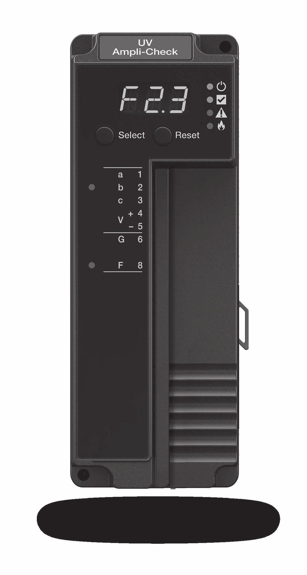
5 LED Array There are four LEDs on the front of the Ampli-Check Flame Amp module that provide quick identification of the system status and any problems that might occur. The status is broadcast to other modules on the platform bus in case they are affected by the inoperable modules. See Table 1 for descriptions. LED Color Description Power No light System does not have power Green System has power CPU Fault Flame Red Green Red No light Yellow No light Table 1. LED Descriptions. No wire sheet or problem with the wire sheet Running SLATE Burner Control Module has detected a fault Running Weak flame is detected No flame is detected LED Display The SLATE system modules have a seven-segment, threeposition LED display used for indicating flame strength. It is also used to identify the module number of the SLATE system. Color Terminal T2 Green Red Terminal T8 Green Off Description Communicating with burner Communication fault Flame No flame Table 2. Terminal LED Meanings. SLATE UV SHUTTER-CHECK FLAME AMPLIFIER 5 R8001S1071
6 Select and Reset Buttons The SLATE system modules have Select and Reset buttons located on the front of the module and beneath the segment display. The Select button is used to scroll through the segment display information. Selector Switch The SLATE Burner Control Module is designed to operate with only one Flame Amplifier Module. The Flame Amplifier Module has a rotary switch on its back side which is factory set to 1. It must be set to 1 for the system to operate properly. See Fig. 2. Installation WARNING Fire or Explosion Hazard Can cause severe injury, death, or property damage. Verification of safety requirements must be performed each time a control is installed on a burner to prevent possible hazardous burner operation. When Installing This Product 1. Read these instructions carefully. Failure to follow them could damage the product or cause a hazardous condition. 2. Check the ratings given in the instructions and on the product to make sure the product is suitable for your application. 3. After installation is complete, check out the product operation as provided in these instructions
7 WARNING Electrical Shock Hazard. Can cause severe injury, death or equipment damage. 1. Disconnect the power supply before beginning installation to prevent electrical shock and equipment damage. More than one power supply disconnect can be involved. 2. Verify the Selector Switch is set to 1. See Fig. 2. ROTARY SWITCH MUST BE IN POSITION 1 Fig. 2. Flame Amplifier Module Selector Switch. M Install the Flame Amplifier on the Sub-Base. See Fig. 3. SLATE UV SHUTTER-CHECK FLAME AMPLIFIER 7 R8001S1071
8 M35383 Fig. 3. Installing the UV Ampli-Check Flame Amplifier on the Sub-Base Module. IMPORTANT 1. Wiring must comply with all applicable codes, ordinances and regulations. 2. Wiring must comply with NEC Class 1 (Line Voltage) wiring. 3. The R8001S1071 should not interfere with the propersafety operation of the controls, limits and interlocks it is monitoring. After installation, check each control, limit and interlock to ensure that it is operating properly. DO NOT PLACE JUMPER WIRES ACROSS THE INSTALLATION CONTROLS, LIMITS AND INTERLOCKS. The SLATE Flame Amplifier module must be mounted in an electrical enclosure with adequate clearance for servicing, installation, and removal of modules
9 CAUTION Equipment Damage Hazard. Incorrect combination of relay module, amplifier and flame detector can cause equipment damage. Installing the Flame Detector Proper flame detector installation is the basis of a safe and reliable flame safeguard installation. Refer to the instructions packed with the flame detector and the equipment manufacturer instructions. Keep the flame signal leadwires as short as possible from the flame detector to the SLATE system. Capacitance increases with leadwire length, reducing the signal strength. The maximum permissible leadwire length depends on the type of flame detector, leadwire and conduit. However, the ultimate limiting factor for the flame detector leadwire is the flame signal. If the flame amplifier is mounted on the DIN rail, it must be placed immediately to the right of the Burner Control Module that it is communicating with. If the flame amplifier is not placed immediately to the right of the Burner Control Module, then it must be externally wired to it via the remote bus connections. SLATE UV SHUTTER-CHECK FLAME AMPLIFIER 9 R8001S1071
10 Wiring 1. Refer to Fig. 4 for proper flame detector wiring. 2. Disconnect power supply before making wiring connections to prevent electrical shock and equipment damage. UV FLAME AMP WITH AMPLI-CHECK MODULE REMOTE BUS 1 a 2 b 3 c 4 V+ 5 V 6 G FLAME SIGNAL INPUT/OUTPUT 7 8 F SECOND REMOTE BUS IS ON SUBBASE M35394 Fig. 4. R8001S1071 SLATE UV Ampli-Check Flame Amplifier wiring
11 3. All wiring must comply with appropriate electrical codes, ordinances and regulations including NEC Class 1 (Line Voltage) wiring where required. 4. Use recommended wire size and type no. 18 copper conductors TTW (60C) or THW (75C) or THNN (90C). 5. Use recommended wire routing: a. Keep the flame signal leadwire as short as possible from the detector to the SLATE module. The maximum permissible leadwire length depends on the type of leadwire, conduit type and leadwire diameter. The ultimate limiting factor for flame signal length is the flame signal voltage. b. Do not run high voltage ignition transformer wires in the same conduit with the flame detection wiring. c. If the flame detector leadwires are not long enough to reach the SLATE electrical connectors, make splices in a junction box. (1) Enclose scanner wiring without armor cable in metal cable or conduit. (2) Follow flame detector Instructions. 6. Check wiring, see Fig. 4. SLATE UV SHUTTER-CHECK FLAME AMPLIFIER 11 R8001S1071
12 Checkout Preliminary Inspection Make certain that: 1. Wiring connections are correct and all terminal screws and electrical connections are tight. 2. Proper flame failure response time is selected. 3. Amplifier is securely mounted on the DIN Rail and bus connector secured to SLATE Burner Control Module. 4. Detectors are properly positioned and cleaned according to Detector Instructions. 5. Correct combination of amplifier and flame detector is used. The flame signal for the pilot alone, the main burner flame alone, and both together must be steady and a minimum of 0.8V. If the flame signal is unsteady, or less than the minimum acceptable voltage, check the flame detector installation and circuitry in the following procedure. 1. Check the supply voltages. Make sure the master switch is closed, connections are correct, and the power supply is of the correct voltage and frequency and is sinusoidal. 2. Check the detector wiring for defects including: a. Incorrect connections. b. Wrong type of wire. c. Deteriorated wire. d. Open circuits. e. Short circuits. f. Leakage paths caused by moisture, soot or accumulated dirt. 3. For all optical detectors, clean the detector viewing window, lens, and inside of the sight pipe as applicable. 4. With the burner running, check the temperature at the detector. If it exceeds the detector maximum rated temperature: a. Add a heat block to stop conducted heat traveling up the sight pipe. b. Add a shield or screen to reflect radiated heat
13 c. Add cooling (refer to sight pipe ventilation in the detector Instructions). 5. Make sure that the flame adjustment is not too lean. 6. Make sure the optical detector is properly sighting the flame. 7. If necessary, resight or reposition the detector. 8. If you cannot obtain proper operation, replace the plug-in amplifier. 9. If you cannot yet obtain proper operation, replace the flame detector. IMPORTANT If you make any changes to the flame detection system, repeat all required Checkout tests in Checkout section of the Instructions for the applicable SLATE module. SLATE UV SHUTTER-CHECK FLAME AMPLIFIER 13 R8001S1071
14
15 SLATE UV SHUTTER-CHECK FLAME AMPLIFIER 15 R8001S1071
16 For more information and detailed instructions on the R8001S1071 and the entire SLATE system please refer to the SLATE User Guide located on our website at Automation and Control Solutions Honeywell International Inc. U.S. Registered Trademark Douglas Drive North 2014 Honeywell International Inc. Golden Valley, MN M.S customer.honeywell.com Printed in U.S.A.
SLATE. Rectification Ampli-Check Flame Amplifier INSTALLATION INSTRUCTIONS R8001V1031
 SLATE Rectification Ampli-Check Flame Amplifier R8001V1031 INSTALLATION INSTRUCTIONS Scan for more information Application SLATE brings configurable safety and programmable logic together into one single
SLATE. Sub-Base Module INSTALLATION INSTRUCTIONS R8001S9001
 SLATE Sub-Base Module R8001S9001 INSTALLATION INSTRUCTIONS Scan for more information Application SLATE brings configurable safety and programmable logic together into one single platform. The platform
SLATE. Burner Control Module INSTALLATION INSTRUCTIONS R8001B2001
 SLATE Burner Control Module R8001B2001 INSTALLATION INSTRUCTIONS Scan for more information Application SLATE brings configurable safety and programmable logic together into one single platform. The platform
R7824, R7847, R7848, R7849, R7851, R7852, R7861, R7886 Amplifiers for 7800 SERIES and R7140 Relay Modules
 R7824, R7847, R7848, R7849, R7851, R7852, R7861, R7886 Amplifiers for 7800 SERIES and R7140 Relay Modules PRODUCT DATA indicate the presence of flame when used with 7800 SERIES and R7140 Relay Modules.
SLATE. Base Module INSTALLATION INSTRUCTIONS R8001A1001
 SLATE Base Module R8001A1001 INSTALLATION INSTRUCTIONS Scan for more information Application SLATE brings configurable safety and programmable logic together into one single platform. The platform can
R7824, R7847, R7848, R7849, R7851, R7852, R7861, R7886 Amplifiers for 7800 SERIES and R7140 Relay Modules
 R7824, R7847, R7848, R7849, R7851, R7852, R7861, R7886 Amplifiers for 7800 SERIES and R7140 Relay Modules PRODUCT DATA indicate the presence of flame when used with 7800 SERIES and R7140 Relay Modules.
R7824, R7847, R7848, R7849, R7851, R7852, R7861, R7886 Amplifiers for 7800 SERIES and R7140 Relay Modules
 R784, R7847, R7848, R7849, R7851, R785, R7861, R7886 Amplifiers for 7800 SERIES and R7140 Relay Modules PRODUCT DATA and R7140 Relay Modules. This is not European Community (CE) approved for EC7810, EC780,
R7824, R7847, R7848, R7849, R7851,R7861, R7886 Amplifiers for 7800 SERIES Relay Modules
 R784, R7847, R7848, R7849, R7851,R7861, R7886 Amplifiers for 7800 SERIES Relay Modules PRODUCT DATA The R7851C Dynamic Self- Optical lame Amplifier is a solid state plug-in amplifier that responds to ultraviolet
Artisan Technology Group is your source for quality new and certified-used/pre-owned equipment
 Artisan Technology roup is your source for quality new and certified-used/pre-owned equipment AST SHIPPIN AND DELIVERY TENS O THOUSANDS O IN-STOCK ITEMS EQUIPMENT DEMOS HUNDREDS O MANUACTURERS SUPPORTED
7800 SERIES RM7888A Relay Module
 7800 SERIES RM7888A Relay Module SPECIFICATION DATA FEATURES APPLICATION The Honeywell RM7888A Relay Module is a microprocessor-based integrated burner control for industrial process semi-automatically
7800 SERIES RM7840E,G,L,M; EC7840L Relay Module
 7800 SERIES RM7840E,G,L,M; EC7840L Relay Module SPECIFICATION DATA Valve Proving features including: VPS test time When (Never, Before, After, Split or Both) FEATURES APPLICATION The Honeywell RM7840 is
7800 SERIES EC7885A/RM7885A Relay Module
 7800 SERIES EC7885A/RM7885A Relay Module SPECIFICATION DATA 1. Torch-ignited main burner using the S445A Start-Stop Station, or any conventional knee or foot operated start-stop station. 2. Torch-ignited
7800 SERIES EC7823/RM7823 Relay Module
 7800 SERIES EC7823/RM7823 Relay Module FEATURES SPECIFICATION DATA APPLICATION The Honeywell EC7823/RM7823 is a microprocessor based Flame Detector Relay that can be fitted with any 7800 SERIES amplifier
7800 SERIES RM7888A Relay Module
 7800 SERIES RM7888A Relay Module FEATURES SPECIFICATION DATA APPLICATION The Honeywell RM7888A Relay Module is a microprocessor-based integrated burner control for industrial process semi-automatically
INSTALLATION INSTRUCTIONS
 SLATE 10 Color Touch Screen Display R8001K1010 INSTALLATION INSTRUCTIONS Scan for more information Application SLATE brings configurable safety and programmable logic together into one single platform.
7800 SERIES 22-Terminal Universal Subbase
 7800 SERIES 22-Terminal Universal Subbase FEATURES PRODUCT DATA Q7800B003/2003/U Metal Wall-mount subbase Q7800A005/2005/U Plastic Wall-mount subbase Quick-mount wiring subbase for all 7800 SERIES Relay
Q7800H Integrated Burner Control Subpanel
 Q7800H Integrated Burner Control Subpanel INSTALLATION INSTRUCTIONS FEATURES Unique subpanel design eliminates extensive wiring in the OEM control panel. One subpanel design covers multiple applications.
7800 SERIES EC7895A,C; RM7895A,B,C,D and RM7896A,B,C,D Relay Modules
 7800 SERIES EC7895A,C; RM7895A,B,C,D and RM7896A,B,C,D Relay Modules SPECIFICATION DATA FEATURES APPLICATION The Honeywell EC7895/RM7895/RM7896 is a microprocessor based integrated burner control for automatically
R7910A SOLA (Hydronic Control) and R7911 SOLA (Steam Control) Systems
 and R7911 SOLA (Steam Control) Systems") R7910A SOLA (Hydronic Control) and R7911 SOLA (Steam Control) Systems APPLICATION The R7910 SOLA hydronic boiler and the R7911 SOLA steam control systems provide heat control, flame supervision, circulation
R7910A SOLA (Hydronic Control) and R7911 SOLA (Steam Control) Systems APPLICATION The R7910 SOLA hydronic boiler and the R7911 SOLA steam control systems provide heat control, flame supervision, circulation
Instructions For A and Flame Simulators
 Instructions For 123514A and 203659 Flame Simulators Application Flame simulators are devices that simulate a flame by reproducing ultraviolet resistance or rectification characteristics of an actual flame.
YP7999A1000 ControLinks Fuel Air Ratio Control Panel
 YP7999A1000 ControLinks Fuel Air Ratio Control Panel FEATURES INSTALLATION INSTRUCTIONS Pre-wired and ready to install Includes the R7999A control, wiring subbase and S7999D1048 touchscreen display Commission,
Honeywell SLATE ICM Platform
 Honeywell SLATE ICM Platform SUBMITTAL SPECIFICATION Note to specifiers: To specify Honeywell SLATE Integrated Combustion Management System with specified packaged boiler manufactures, Copy and Paste both
C7915A Infrared Flame Detector
 C795A Infrared Flame Detector PRODUCT DATA When installed properly, can supervise the pilot flame and/ or the main burner flame. Mounts easily on a standard 3/ inch sight pipe. The infrared sensor plugs
C7005A,B Gas Pilot and Flame Rod Assemblies
 C7005A,B Gas Pilot and Flame Rod Assemblies FEATURES PRODUCT DATA Used with Honeywell controls using the flame rectification principle. C7005A is for continuous pilot applications. It includes an insulated
C554A Cadmium Sulfide Flame Detector
 C554A Cadmium Sulfide Flame Detector FEATURES PRODUCT DATA Cadmium sulfide sensing element provides faster response than bimetal sensors. On flame failure, the cad cell causes the oil primary control to
MBCE-110/230UV Flame Sensor Module
 MBCE-1002 FEBRUARY 3, 2017 MBCE-110/230UV Flame Sensor Module DESCRIPTION The MBCE-110/230UV modules provide visual indication and electrical outputs that signal the user regarding flame presence in a
7800 SERIES Relay Modules
 7800 SERIES Relay Modules CHECKOUT AND TEST This publication provides general checkout and troubleshooting procedures for the 7800 SERIES Relay Modules. SYSTEM CHECKOUT IMPORTANT Perform all Static Checkout
C7007A, C7008A, C7009A Flame Rod Holder & Flame Rod Assemblies
 Flame Rod Holder & Flame Rod Assemblies The small size of these devices enable their application to flame detection in installations where space is limited. The holder and flame rod assemblies facilitate
7800 SERIES EC7890A,B; RM7890A,B,C Relay Module
 7800 SERIES EC7890A,B; RM7890A,B,C Relay Module SPECIFICATION DATA EC7890 APPLICATION RM7890 The Honeywell EC7890A,B/RM7890 is a microprocessor based integrated burner control for automatically fired gas,
R7910A SOLA (Hydronic Control) and R7911 SOLA (Steam Control) Systems
 and R7911 SOLA (Steam Control) Systems") R7910A SOLA (Hydronic Control) and R7911 SOLA (Steam Control) Systems INSTALLATION INSTRUCTIONS APPLICATION The R7910 SOLA hydronic boiler and the R7911 SOLA steam control systems provide heat control,
R7910A SOLA (Hydronic Control) and R7911 SOLA (Steam Control) Systems INSTALLATION INSTRUCTIONS APPLICATION The R7910 SOLA hydronic boiler and the R7911 SOLA steam control systems provide heat control,
Eclipse Self-Check UV Scanner
 856 Instruction Manual 10/18/2010 Eclipse Self-Check UV Model 5602-91 Version 1 Introduction The self-check UV is used for continuous gas or oil flames. A mechanical shutter in the scanner closes briefly
RA890G Protectorelay Primary Control
 Protectorelay Primary Control The RA890G Protectorelay control provides solid state electronic safeguard protection for industrial and commercial gas, oil, or combination gas-oil burners. Designed for
ELECTRONIC FLAME SUPERVISION MULTI-BURNER
 MULTI-BURNER MODEL: SENS-A-FLAME II Revision: 0 7112 DESCRIPTION Model 7112 Sens-A-Flame II is a second generation solid-state programmable combustion safeguard for supervising multiple burner ovens, furnaces,
Commercial/Industrial Combustion Control Level Three Announcement
 Commercial/Industrial Combustion Control Level Three Announcement SUBJECT: C6097 requiring venting Model Numbers Affected: C6097A and B Ref. Number L3-08-006 Issue Date 12/9/08 Author P.Yuen/L.Ziller Date
7800 SERIES: EC7895A,C; RM7895A,B,C,D; RM7896A,B,C,D RM7897A,C and RM7898A Relay Modules
 7800 SERIES: EC7895A,C; RM7895A,B,C,D; RM7896A,B,C,D RM7897A,C and RM7898A Relay Modules SPECIFICATION DATA The RM7897A1002 offers selectable pilot operation, intermittent on terminal 8 or interrupted
7800 SERIES RM7824A Relay Module
 7800 SERIES RM7824A Relay Module FEATURES PRODUCT DATA APPLICATION The Honeywell RM7824A Relay Module is a 24 Vdc microprocessor-based integrated burner control for automatically fired gas, oil or combination
SIL3. C7961E,F Dynamic Self-Check Ultraviolet Flame Detector. Capable APPLICATION FEATURES PRODUCT DATA. Contents
 C796E,F Dynamic Self-Check Ultraviolet Flame Detector PRODUCT DATA C796F C796E Detectors can be mounted horizontally, vertically or at any other angle providing the orientation arrow is pointing down.
RM7838A 7800 SERIES Relay Modules
 RM788A 7800 SERIES Relay Modules APPLICATION The Honeywell RM788A is a microprocessor-based integrated burner control for semi-automatically fired gas, oil, or combination fuel single burner applications.
C7232A,B Sensor and Controller CARBON DIOXIDE SENSOR
 C7232A,B Sensor and Controller CARBON DIOXIDE SENSOR PRODUCT DATA C7232A C7232B FEATURES Used for CO 2 based ventilation control. Models available with LCD that provides sensor readings and status information.
7800 SERIES RM7840E,G,L,M Relay Module
 7800 SERIES RM7840E,G,L,M Relay Module APPLICATION SPECIFICATION DATA The Honeywell RM7840 is a microprocessor based integrated burner control for automatically fired gas, oil or combination fuel single
C7061A,F Dynamic Self-Check Ultraviolet Flame Detector
 C706A,F Dynamic Self-Check Ultraviolet Flame Detector FEATURES PRODUCT DATA C706F APPLICATION C706A The C706A,F are dynamic self-checking flame detectors for sensing the ultraviolet radiation generated
C7232A,B Sensor and Controller
 C7232A,B Sensor and Controller CARBON DIOXIDE SENSOR FEATURES PRODUCT DATA C7232A C7232B Used for CO 2 based ventilation control. Models available with LCD that provides sensor readings and status information.
C7061A,F Dynamic Self-Check Ultraviolet Flame Detector
 C706A,F Dynamic Self-Check Ultraviolet Flame Detector PRODUCT DATA FEATURES APPLICATION C706F C706A The C706A,F are dynamic self-checking flame detectors for sensing the ultraviolet radiation generated
C7061C/F ULTRA VIOLET FLAME DETECTOR FEATURES APPLICATION PRODUCT HANDBOOK. Contents
 C7061C/F ULTRA VIOLET FLAME DETECTOR PRODUCT HANDBOOK APPLICATION The C7061C/F are flame detectors for sensing the ultraviolet radiation generated by the combustion of gas, oil, or other fuels. Explosion-proof
C7061A,F Dynamic Self-Check Ultraviolet Flame Detector
 C706A,F Dynamic Self-Check Ultraviolet Flame Detector FEATURES PRODUCT DATA C706F APPLICATION C706A The C706A,F are dynamic self-checking flame detectors for sensing the ultraviolet radiation generated
MBCE-110/230FR Flame Sensor Module
 MBCE-1001 APRIL 13, 2012 MBCE-110/230FR Flame Sensor Module DESCRIPTION The MBCE-110/230FR modules provide visual indication and electrical outputs that signal the user regarding flame presence in a combustion
Eclipse 90 UV Scanner Model A Version 1
 85 Instruction Manual 10/14/010 Eclipse 90 UV Model 5600-90A Version 1 C US Introduction This sensor features a high sensitivity ultraviolet (UV) tube for monitoring gas or oil flames that cycle on and
C7061A,F Dynamic Self-Check Ultraviolet Flame Detector
 C706A,F Dynamic Self-Check Ultraviolet Flame Detector FEATURES PRODUCT DATA C706F APPLICATION C706A The C706A,F are dynamic self-checking flame detectors for sensing the ultraviolet radiation generated
YP7899C SERIES Burner Management Panel
 YP7C1000 700 SERIES Burner Management Panel INSTALLATION INSTRUCTIONS 65-00, ST700A,C 700 SERIES Plug-In Purge Timer 65-0, S710M Modbus Module 60-06, C707, C7035, C70, C77 Minipeeper UV Flame Detector
SIL3. C7012A,C,E,F,G Solid State Purple Peeper Ultraviolet Flame Detectors. Capable FEATURES APPLICATION PRODUCT DATA. Contents C7012A,E,G C7012C,F
 C70A,C,E,F,G Solid State Purple Peeper Ultraviolet Flame Detectors PRODUCT DATA APPLICATION The C70A,C,E,F,G Flame Detectors are solid-state electronic devices for sensing the ultraviolet radiation emitted
R7120M 7800 SERIES Relay Modules
 R7120M 7800 SERIES Relay Modules INSTALLATION INSTRUCTIONS APPLICATION The R7120M are microprocessor-based integrated burner controls for automatically fired gas, oil, or combination fuel single burner
RM7895A,B,C,D/EC7895A,C; RM7896A,B,C,D 7800 SERIES Relay Modules
 RM79A,B,C,D/EC79A,C; RM796A,B,C,D 700 SERIES Relay Modules INSTALLATION INSTRUCTIONS APPLICATION The RM79A,B,C,D/EC79A,C; RM796A,B,C,D are microprocessor-based integrated burner controls for automatically
CR Series Command Relays
 CR Series Command Relays FEATURES INSTALLATION INSTRUCTIONS Patented 35mm Din-rail mounting flange (US Patent 7,416,421) SPDT Form 1C Relay contacts Pilot duty rated LED status indication Stackable for
UV Scanner. Model Specification. Introduction. 854 Instruction Manual
 854 Instruction Manual 10/11/010 UV Model 5600-91 C US Introduction This sensor features a high temperature and high sensitivity ultraviolet (UV) tube for monitoring gas or oil flames in applications that
T7079A,B Solid State Remote Temperature Controllers
 T7079A,B Solid State Remote Temperature Controllers FEATURES PRODUCT DATA Switch selection of heat or cool mode. Temperature sensing up to 400 feet. Does not require field calibration. 0K NTC temperature
C7012A,C,E,F,G Solid State Purple Peeper Ultraviolet Flame Detectors
 C70A,C,E,F,G Solid State Purple Peeper Ultraviolet Flame Detectors PRODUCT DATA APPLICATION The C70A,C,E,F,G Flame Detectors are solid-state electronic devices for sensing the ultraviolet radiation emitted
7800 SERIES S7830 Expanded Annunciator
 7800 SERIES S7830 Expanded Annunciator PRODUCT DATA FEATURES APPLICATION The S7830 Expanded Annunciator is an enhancement module for use with 7800 SERIES Relay Modules. The S7830 is a microprocessor-based
7800 SERIES EC7810A, EC7820A Relay Module
 7800 SERIES EC780A, EC780A Relay Module PRODUCT DATA GENERAL The Honeywell EC780A or EC780A Relay Module is a microprocessor based integrated burner control for automatically fired gas, oil, or combination
RM7897A,C 7800 SERIES Relay Modules
 RM7897A,C 7800 SERIES Relay Modules INSTALLATION INSTRUCTIONS APPLICATION The RM7897A,C are microprocessor-based integrated burner controls for automatically fired gas, oil, or combination fuel single
Power Supply Display Module PSDM. Installation and Operation Manual
 Power Supply Display Module PSDM Installation and Operation Manual Read this manual before using this product. Failure to follow the instructions and safety precautions in this manual can result in serious
MBCE-110/230FR Flame Sensor Module
 MBCE-1001 FEBRAURY 6, 2017 MBCE-110/230FR Flame Sensor Module exida FMEDA SIL2 SEE NOTE 1 ON PAGE 4 DESCRIPTION The MBCE-110/230FR modules provide visual indication and electrical outputs that signal the
RM7890; RM Vac 7800 SERIES Relay Modules
 RM7890; RM7895 00 Vac 7800 SERIES Relay Modules PRODUCT DATA The RM7890; RM7895 provides on/off automatic burner sequencing, flame supervision, system status indication, system or self-diagnostics and
Flame Safeguard Fault Code Diagnostics
 Vino s Vine Tech Tips Series 02/2013 Flame Safeguard Fault Code Diagnostics As manager of Tech Services, it probably comes as no surprise I spend some time discussing fault codes and corresponding corrective
Cleaver-Brooks CB780/CB784 Operation and Maintenance Manual
 $25.00 Cleaver-Brooks CB780/CB784 Operation and Maintenance Manual 750-166 DIVISION OF AQUA-CHEM, INC. TO: Owners, Operators and/or Maintenance Personnel This manual presents information that will help
L8005A,B; LS8005A,C,D Electronic Pool and Spa Controllers
 Electronic Pool and Spa Controllers The L8005A,B and LS8005A,C,D Electronic Pool and Spa Controllers are used in pool, spa, and hot tub applications to control water temperature. Remote Potentiometer L8005A,B
Distributed By: M&M Control Service, INC
 APPROVED The UV1A3/6, UV2/UV2A6/UV2C, 45UV2, 45UV3, UV90-3/6/9 Scanners are used with the M-Series, M-Series II, MicroM, FlameWorx, MB-2 and D-Series controls as well as the Fireye FLAME-MONITOR TM, BurnerLogix
P7810A-D Pressuretrol Controller
 P780A-D Pressuretrol Controller P780C, D P780A, B FEATURES PRODUCT DATA Use only with steam, air or noncombustible gases that do not corrode the pressure sensing element. Models available with on-off control
C7061A Dynamic Self-Check Ultraviolet Flame Detector
 C7061A Dynamic Self-Check Ultraviolet Flame Detector FEATURES PRODUCT DATA Oscillating shutter interrupts ultraviolet radiation reaching the UV sensor 12 times per minute to provide the UV sensor tube
Honeywell Primary Control Cross Reference
 Honeywell Primary Control Cross Reference Page Pages, Page, Page Page Page Pages 9, 0 Page Pages, Page Pages, Page Page Pages 9,0 R, R0, R, R90B, RA90B, R90C, R, R90B RA90B, R90C, RA90C, RA90XB,XC, RA90D
FIREYE M4RT1 FLAME SAFEGUARD CONTROLS DESCRIPTION
 M-4000 JANUARY 29, 200 FIREYE M4RT1 FLAME SAFEGUARD CONTROLS WARNING: Selection of this control for a particular application should be made by a competent professional, licensed by a state or other government
C7004B Flame Rod Holder
 Honeywell These Flame Rod Holders facilitate the use of flame rods for flame proving on gas burners or gas-pilot ignited oil burners controlled by electronic flame safeguard control systems. C7004B Flame
7800 SERIES S7800A2142 Keyboard Display Module
 7800 SERIES S7800A2142 Keyboard Display Module PRODUCT DATA The S7800A2142 KDM offers the following technical advancements to the 7800 SERIES devices: APPLICATION The S7800A2142 Keyboard Display Module
RM7895A,B,C,D/EC7895A,C; RM7896A,C,D 7800 SERIES
 RM7895A,B,C,D/EC7895A,C; RM7896A,C,D 7800 SERIES Relay Modules INSTALLATION INSTRUCTIONS APPLICATION The RM7895A,B,C,D/EC7895A,C; RM7896A,B,C,D are microprocessor-based integrated burner controls for automatically
configurable safety and programmable logic SLATE Integrated Combustion Equipment Management The revolutionary integration of
 SLATE Integrated Combustion Equipment Management The revolutionary integration of configurable safety and programmable logic in a single, modular platform Complexity. This is today. Individual components
R7140G,L,M Burner Control Modules
 R0G,L,M Burner Control Modules FEATURES INSTALLATION INSTRUCTIONS APPLICATION The Honeywell R0G,L,M Burner Control Modules are microprocessor-based integrated burner controls for automatically fired gas,
7800 Series RM7888A Relay Module
 7800 Series RM7888A Relay Module FEATURES PRODUCT DATA APPLICATION The Honeywell RM7888A Relay Module is a microprocessor based, integrated burner control for industrial process semiautomatically fired
Advanced Ultraviolet Burner Controller
 No. CP-SS-7E Advanced Ultraviolet Burner Controller Model AUR300C/AUR30C Overview The AUR300C Advanced Ultraviolet Burner Controller and AUR30C Advanced Ultraviolet Burner Controller with Communication
AUR300C, AUR350C. Advanced Ultraviolet Burner Controller
 No. CP-SS-7E Overview The AUR300C is a burner controller with a dynamic selfchecking function and is used in combination with the AUD300C or AUD00C Advanced Ultraviolet Flame Detector. This AUR300C controls
AUR300C. Advanced Ultraviolet Burner Controller
 No. CP-SS-1807E AUR300C Advanced Ultraviolet Burner Controller Overview The AUR300C is a burner controller with a dynamic selfchecking function and is used in combination with the AUD300C or AUD500C Advanced
RM7890D; RM7895E,F 7800 SERIES Relay Modules
 RM7890D; RM7895E,F 7800 SERIES Relay Modules PRODUCT DATA The RM7890D; RM7895E,F provides automatic burner sequencing, flame supervision, system status indication, system or self-diagnostics and troubleshooting.
Fireye FLAME SCANNERS
 UV7A4 SC-107 APRIL 3, 2013 Fireye SCANNERS UV7SC UV7R4 UV Non Self-Checking Scanner Models: UV7A4, UV7R4 UV Self-Check Scanner Model: UV7SC DESCRIPTION The non self-check UV7A4, UV7R4 and self-check UV7SC
Solid Core and Split Core 0-5, 0-10 Vdc Output Current Sensors CTS-05,10; CTP-05,-10
 Solid Core and Split Core 0-5, 0-10 Vdc Output Current Sensors CTS-05,10; CTP-05,-10 DESCRIPTION FEATURES PRODUCT DATA Solid and Split Core Vdc Output Current Transmitters. Fast Response Time. Integral
RM7890A1056, RM7890B SERIES
 RM7890A1056, RM7890B1048 7800 SERIES Relay Modules INSTALLATION INSTRUCTIONS APPLICATION The Honeywell RM7890A1056 and RM7890B1048 Relay Modules are microprocessor based integrated burner controls for
SERIES VAC Microprocessor-Based Direct Spark Ignition Control with Inducer Blower Relay FEATURES APPLICATIONS SPECIFICATIONS DESCRIPTION
 R SERIES 35-61 24 VAC Microprocessor-Based Direct Spark Ignition Control with Inducer Blower Relay F-35-61 August 2015 FEATURES Safe start with DETECT-A-FLAME flame sensing technology Custom pre-purge
FIREYE C9707A ALL FUEL SCANNER
 65-8065 APRIL 11, 2013 FIREYE C9707A ALL FUEL SCANNER The C9707A All Fuel Scanner is used with the FIREYE R9107A Flame Controller to provide continuous monitoring of burner flames in industrial and utility
Solid Core and Split Core 4-20 ma Output Current Sensors CTS-20; CTP-20
 Solid Core and Split Core 4-20 ma Output Current Sensors CTS-20; CTP-20 PRODUCT DATA FEATURES Solid or split core loop-powered current transmitters Fast response time Integral DIN rail mounting flange
Safety. Operating instructions UV sensor UVS 10 DANGER WARNING. Contents CAUTION Edition Please read and keep in a safe place
 8.. Edition 08.0 D GB F NL I E DK S N P GR TR CZ PL RUS H www.docuthek.com Operating instructions UV sensor UVS 0 Translation from the German 008 009 Elster GmbH Contents UV sensor UVS 0......................
Refer to Bulletin E-1101 for detailed information on the FLAME-MONITOR System.
 The Fireye EP260, EP270 (early spark termination), or EP265 (pilot stabilization) programmer modules are used with the FLAME-MONITOR Burner Management Control System (P/N E110). Several operational characteristics
Flame relay units are necessary in most industrial combustion systems. These flame relay models are capable of meeting most application needs.
 Flame relay units are necessary in most industrial combustion systems. These flame relay models are capable of meeting most application needs. Hauck Part No. Voltage Mounting Base Flame Detectors Display
Field Start-Up Sheet Direct Fired Gas Equipment
 Customer: Sales Representative: Model Number: Serial Number: Field Start-Up Sheet Direct Fired Gas Equipment ***Please Print*** INITIAL INSPECTION I. Installer Responsibilities 1. Remote Panel: All interconnecting
IS Series Pressure Sensing Switches
 IS Series Pressure Sensing Switches FEATURES INSTALLATION INSTRUCTIONS IS3 PRESSURE SWITCH APPLICATION IS2 PRESSURE SWITCH The IS Series of pressure sensing switches offers the same proven compression
Flame Rod Manual. Publication Rev A
 Publication INTRODUCTION This manual contains information for the Flame Rod Flame Detection system from Forney Corporation, 16479 North Dallas Parkway, Suite 600 Addison, TX 75001. All personnel should
C6097A,B Pressure Switches
 C6097A,B Pressure Switches FEATURES PRODUCT DATA APPLICATION The C6097 Pressure Switches are safety devices used in positive-pressure or differential-pressure systems to sense gas or air pressure changes.
FIREYE FLAME SCANNERS
 SC-103 JUNE 7, 2018 48PT1 (Obsolete) FIREYE S 48PT2 INFRARED: 48PT1, 48PT2 and 48PT2-CEX ROD: 69ND1 For UV Self-Check Scanners use SC-101 For Hazardous Locations or NEMA 4X Scanners use SC-106 For Non
Instruction Manual 826 7/22/2009. Eclipse Bi-Flame Dual Burner Monitoring System Model 6500 Version 1
 Instruction Manual 826 7/22/2009 Eclipse Bi-Flame Dual Burner Monitoring System Model 6500 Version 1 Copyright Copyright 2003 by Eclipse, Inc. All rights reserved worldwide. This publication is protected
MBUV-100D, MBUVS-100D MBIR-100D, MBFR-100D DIN RAIL MOUNT FLAMEWORX MODULES
 MBD-00 FEBRUARY 00 MBUV-00D, MBUVS-00D MBIR-00D, MBFR-00D DIN RAIL MOUNT FLAMEWORX MODULES APPROVED Year 000 Compliant in accordance with BSI document DISC PD000-I:998 DESCRIPTION Fireye offers a complete
IRIS IP65 IRIS UNISCAN APPLICATION MANUAL
 IRIS IP65 IRIS UNISCAN APPLICATION MANUAL 01/08/05 DESCRIPTION TABLE OF CONTENTS PAGE IRIS - UNISCAN... 1 SPECIFICATION... 1 SUPPLY VOLTAGE: -... 1 OUTPUTS: -... 1 TRANSMISSION: -... 1 CABLE: -... 1 FLAME
MASTER JOCKEY PUMP CONTROLLER. Model JPCE INSTRUCTION MANUAL. C 2018 Master Control Systems, Inc
 MASTER JOCKEY PUMP CONTROLLER Model JPCE INSTRUCTION MANUAL C 2018 Master Control Systems, Inc TABLE OF CONTENTS Important Safety Information. Page 3 General Description and Installation.. Page 4 Model
THERMAL BUILDING SOLUTIONS EN-TraceTekTTSIM1A-IM-H /16
 TraceTek TTSIM-1A TraceTek Sensor Interface Module with Relay Installation/OPERATION Instructions Approvals and Certifications TYPE NM General Signaling Equipment 76LJ Only AC versions are UL listed and
SOLID STATE Burner Management Controls SERIES D40-41
 D-4041 JULY 8, 2013 SOLID STATE Burner Management Controls SERIES D40-41 70D41 ONLY 70D40 ONLY DESCRIPTION FIREYE Series D40-41 Burner Management Controls provide ignition and flame failure protection