Heliox UV. Model Heliox LP P Heliox LP P Heliox LP P300
|
|
|
- Miranda Matthews
- 5 years ago
- Views:
Transcription


1 EN FR ES IT DE PT UV TREATMENT SYSTEM SYSTÈME DE TRAITEMENT UV SISTEMA DE TRATAMIENTO UV SISTEMA DI TRATTAMENTO UV UV-BEHANDLUNG-SYSTEM SISTEMA DE TRATAMENTO UV Heliox UV EN PE Model Heliox LP P Heliox LP P Heliox LP P300 EN FR ES IT DE PT INSTALLATION AND MAINTENANCE MANUAL MANUEL D INSTALLATION ET D ENTRETIEN MANUAL DE INSTALACION Y MANTENIMIENTO MANUALE DI INSTALLAZIONE E MANUTENZIONE EINBAU-UND BETRIEBSANLEITUNG MANUAL DE INSTRUÇOES E MANUTENÇAO
2

3 ENGLISH IMPORTANT: The instruction manual you are holding includes essential information on the safety measures to be implemented for installation and start-up. Therefore, the installer as well as the user must read the instructions before beginning installation and start-up. Keep this manual for future reference. Disposal of waste electrical and electronic domestic systems in the European Union. All the products marked with this symbol indicates that the product shall not be mixed or disposed with your household waste at their end of use. It is responsibility of the user to eliminate this kind of wastes depositing them in a recycling point adapted for the selective disposal of electrical and electronic wastes. The suitable recycling and treatment of these wastes contributes in essential way to the preservation of the Environment and the health of the users. For further information regarding the points of collection of this type of wastes, please contact to the dealer where you acquired the product or to your municipal authority. For optimum performance of the HELIOX UV LP Treatment System, we recommend you to follow the instructions given below: 1. CHECK THE CONTENTS OF THE PACK: You should find the following elements inside the box: UV reactor. Flow switch FS-1+ cable (3 m. / 9.8 ft.) (1). Control panel. Lamp power cables LP-0410 x n (5 m. /16.4 ft..). (1) (n, depending on the number of lamps). Micro-switch cable LP-025/M x1 (5 m. /16.4 ft..). (1). Operation Manual. (1) Custom cable lengths may be supplied on demand. 2. GENERAL FEATURES: The germicidal effects of ultraviolet light (UV) with wavelengths around 260 nm are well known for over 100 years. Its use has been increasing in recent years as it presents a number of advantages over chemical disinfection systems, since virtually UV light no alters the physical and chemical composition of water, it is very effective against any type of microorganism (algae, bacteria, viruses, fungi, yeasts, etc.) further minimizing the risks of handling and dosing of potentially hazardous chemicals. Moreover, UV treatment reduces the levels of combined chlorine in water, thereby producing significant water savings by reducing the volume and frequency of renewal of pool water. The HELIOX UV LP treatment system in addition to maintaining a certain level of chlorine in water, ensure the sanitary quality of pool water. The HELIOX UV LP treatment system will operate when the pool recirculation (pump and filter) is operational. The HELIOX UV LP treatment systems are designed and manufactured with the latest technology in UV treatment of water, thus ensuring continuous operation and minimal maintenance. o Electronic ballast with integrated control (high efficiency + 98%). o Operation hour counter. o Input for external flow switch. o Alarm output. o AMALGAM low-pressure UV lamps. o Lamp lifetime: hours (depending on the number of ignitions). 1
4 3. CERTIFICATIONS: The HELIOX UV LP range of systems are certified for pool and spa end use: Certified products: PE versions: Heliox UV LP P Heliox UV LP P Heliox UV LP P300 EC Declaration of Conformity The products listed above are in compliance with: o o o Low Voltage Directive 2006/95/EC. Electromagnetic Compatibility Directive 2004/108/EC. Directive ROHS 2011/65/EC. I.D. ELECTROQUIMICA, S.L. Pol. Ind. Atalayas, c./ Dracma R-19 E Alicante Spain Gaspar Sánchez General Manager 2
 is provided on this unit to connect a minimum No. 8 AWG for US (UL) and a No.")
5 . IMPORTANT SAFETY INSTRUCTIONS WARNING: when installing and using electrical equipment, basic safety precautions should always be followed, including the following: READ AND FOLLOW ALL THE INSTRUCTIONS A yellow-green wire connector marked (*) is provided on this unit to connect a minimum No. 8 AWG for US (UL) and a No. 6 AWG for Canada (CSA) solid copper conductor between this unit and any metal equipment, metal enclosures of electrical equipment, metal water pipe or conduit within 5 feet (1.5 m.) of the unit. One bonding lug marked (*) is provided on the head of the UV chamber suitable for No. 8 AWG (US) and No. 6 AWG (Canada) and secured to the chamber by paint breaking washer and nut. (*) IEC 60417, symbol 5019 This product must be connected to a circuit protected by a ground fault circuit interrupter. The equipment should be installed and handled by truly qualified people. Current electrical and accident prevention regulations should be followed. Under no circumstances will the manufacturer be held responsible for the assembly, installation or start-up, nor any handling or fitting of components unless they are carried out on its premises. Check all the electrical connectors are well tightened to avoid false contacts and their consequent overheating. Install the control panel so that the cooling grids (if exist) are not obstructed. For indoor use only. This unit is not intended for outdoor use. Prior to the installation or replacement of any system component make sure it has been previously disconnected from the mains, and there is no water flow through it. Use only spare parts supplied by AstralPool. Never remove the lock nut of the quartz sleeve when the water is recirculating through the UV reactor as it could be expelled and causing damage. 3


6 The UV light generated by this equipment can cause serious damage if the eyes or skin are exposed directly to the lamp. Never connect the system when the lamp is out of the reactor. Do not handle the UV lamps until completely cold. Always handle the UV lamp with gloves, as fat and other impurities deposited on the surface may reduce its performance and durability. In case you have to clean the lamp surface use a soft cloth soaked with alcohol. SAVE THE INSTRUCTIONS 4
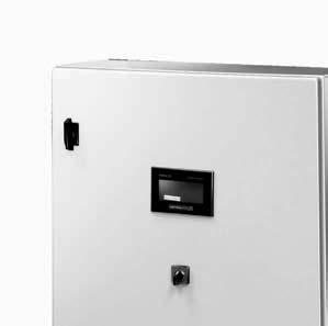
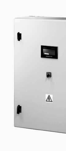
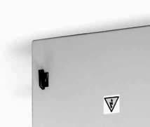
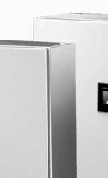
7 4. SYSTEM DESCRIPTION Fig Control panel. 7.- Inputs for sensor cables. 2.- Touchscreen. 8.- UV chamber. 3.- Main switch. 9.- Cover. 4.- Power cable input Stands. 5.- Output for UV reactor Ground cable D200 inlet/outlet flanges. 6.- Outputs for lamp power cables 12.- Flow-switch (FS-1). 5

8 5. INSTALLATION: 5.1. General considerations In order to guarantee a good state of conservation, the HELIOX UV LP system must be installed in a dry and well ventilated place at the technical room. The protection degree of HELIOX UV LP systems does not allow outdoor installation. The temperature at the installation area must be within 36 o F (2 o C) and 104 o F (40 o C) and the relative humidity must not exceed 80%. Install the unit as far away as possible from any storage of chemical products and sources of moisture. Warning Beware of corrosive atmosphere formation due to ph decreasing solutions (specially, those ones based on hydrochloric acid "HCl"). Do not install the HELIOX UV LP system near to any stores of these chemicals. We strongly recommend the use of chemicals based on sodium bisulphate or diluted sulphuric acid Installation of the UV reactor The reactor of HELIOX UV LP systems must be installed HORIZONTALLY, as shown in the recommended installation diagram (Figs. 3). Warning Observe flow direction indications located on the UV chamber. The reactor of the HELIOX UV LP/LP+ systems is made of polyethylene within which are housed the UV lamps. The HELIOX UV LP system should always be installed after the filtration system, and before any other device in the installation such as heat pumps, control systems, dosage systems, salt electrolysis systems, etc. The installation of the UV system should allow easy access to the UV lamp by the user. The location of the HELIOX UV LP system must have an effective dimensions that allow the complete removal of the UV lamp from the sleeve (approximately 2 m.). It is highly recommended to install the HELIOX UV LP system in a place of the pipe that can be easily isolated from the rest of the installation by two valves, so that the tasks of maintenance can be carried out with no need of partial or total draining of the swimming pool. Where the system is installed on a by-pass (recommended option), a valve to regulate the flow must be introduced. Warning Prior to the installation or replacement of any system component make sure it has been previously disconnected from the mains, and there is no water flow through it. Use only spare parts supplied by AstralPool. One bonding lug marked (*) are provided on the head of the UV chamber suitable for No. 8 AWG (US) and No. 6 AWG (Canada) and secured to the chamber by paint breaking washer and nut. Fig. 2 6
9 Legend 1. Filter. 2. Pump. 3. UV reactor. 4. Other equipment (dosage pumps, controllers, heat exchangers, etc.). 5. Flow-switch. Fig.3. HELIOX UV LP systems. Recommended installation diagram Installation of the control panel Always install the CONTROL PANEL of the HELIOX UV LP system vertically and on a rigid surface (wall), so that the touchscreen located on the front panel is at the level of the eyes. Cooling fan and grids (if exist) must not be blocked. Warning The equipment should be assembled and handled by truly qualified people. Current electrical and accident prevention regulations should be followed. Do not attempt to alter the system to operate at a different voltage. Both the power of the HELIOX UV LP system control panel and the interconnection of the UV lamp and the sensors must be made at the terminal block at the base inside the control panel. The control panel base has a series of cable glands for the correct fixation of the power cables and sensors. In any case the length or section thereof should be amended, without first consulting an AstralPool authorized technician. Warning Use copper conductors only. Permanently connected. 7
10 CONTROL PANEL: FIELD WIRING DIAGRAM LP P95 model T. block Control panel input Cable Wire description PE GROUND 1 POWER 230 VAC / Hz. / 1-phase (1) PHASE 2 NEUTRAL PE UV REACTOR BONDING (2) GROUND 3 UV LAMP-1/1 4 UV LAMP-1/2 BLACK 2 LAMP 1 LP-0410/1 5 UV LAMP-1/3 BLACK 3 6 UV LAMP-1/4 BLACK 4 7 UV LAMP-2/1 8 UV LAMP-2/2 BLACK 2 LAMP 2 LP-0410/2 9 UV LAMP-2/3 BLACK 3 10 UV LAMP-2/4 BLACK FLOW SWITCH INPUT POTENTIAL-FREE CONTACT 29 SW-1 HEAD DETECTOR LP-025-M 30 SW-2 BLACK ALARM OUTPUT (3) POTENTIAL-FREE CONTACT (1) Not supplied with the unit. (2) Not supplied with the unit. Bonding must be made with a solid copper conductor minimum No. 8 AWG (USA) / 6 AWG (Canada). (3) Contact closed in case of active alarm. LP P140 model T. block Control panel input Cable Wire description PE GROUND 1 POWER 230 VAC / Hz. / 1-phase (1) PHASE 2 NEUTRAL PE UV REACTOR BONDING (2) GROUND 3 UV LAMP-1/1 4 UV LAMP-1/2 BLACK 2 LAMP 1 LP-0410/1 5 UV LAMP-1/3 BLACK 3 6 UV LAMP-1/4 BLACK 4 7 UV LAMP-2/1 8 UV LAMP-2/2 BLACK 2 LAMP 2 LP-0410/2 9 UV LAMP-2/3 BLACK 3 10 UV LAMP-2/4 BLACK 4 11 UV LAMP-3/1 12 UV LAMP-3/2 BLACK 2 LAMP 3 LP-0410/3 13 UV LAMP-3/3 BLACK 3 14 UV LAMP-3/4 BLACK FLOW SWITCH INPUT POTENTIAL-FREE CONTACT 29 SW-1 HEAD DETECTOR LP-025-M 30 SW-2 BLACK ALARM OUTPUT (3) POTENTIAL-FREE CONTACT (1) Not supplied with the unit. (2) Not supplied with the unit. Bonding must be made with a solid copper conductor minimum No. 8 AWG (USA) / 6 AWG (Canada) (3) Contact closed in case of active alarm. 8
11 LP P300 model T. block Control panel input Cable Wire description PE GROUND 1 POWER 230 VAC / Hz. / 1-phase (1) PHASE 2 NEUTRAL PE UV REACTOR BONDING (2) GROUND 3 UV LAMP-1/1 4 UV LAMP-1/2 BLACK 2 LAMP 1 LP-0410/1 5 UV LAMP-1/3 BLACK 3 6 UV LAMP-1/4 BLACK 4 7 UV LAMP-2/1 8 UV LAMP-2/2 BLACK 2 LAMP 2 LP-0410/2 9 UV LAMP-2/3 BLACK 3 10 UV LAMP-2/4 BLACK 4 11 UV LAMP-3/1 12 UV LAMP-3/2 BLACK 2 LAMP 3 LP-0410/3 13 UV LAMP-3/3 BLACK 3 14 UV LAMP-3/4 BLACK 4 15 UV LAMP-4/1 16 UV LAMP-4/2 BLACK 2 LAMP 4 LP-0410/4 17 UV LAMP-4/3 BLACK 3 18 UV LAMP-4/4 BLACK 4 19 UV LAMP-5/1 20 UV LAMP-5/2 BLACK 2 LAMP 5 LP-0410/5 21 UV LAMP-5/3 BLACK 3 22 UV LAMP-5/4 BLACK 4 23 UV LAMP-6/1 24 UV LAMP-6/2 BLACK 2 LAMP 6 LP-0410/6 25 UV LAMP-6/3 BLACK 3 26 UV LAMP-6/4 BLACK 4 27 UV LAMP-7/1 28 UV LAMP-7/2 BLACK 2 LAMP 7 LP-0410/7 29 UV LAMP-7/3 BLACK 3 30 UV LAMP-7/4 BLACK FLOW SWITCH INPUT POTENTIAL-FREE CONTACT 33 SW-1 HEAD DETECTOR LP-025-M 34 SW-2 BLACK ALARM OUTPUT (3) POTENTIAL-FREE CONTACT (1) Not supplied with the unit. (2) Not supplied with the unit. Bonding must be made with a solid copper conductor minimum No. 8 AWG (USA) / 6 AWG (Canada) (3) Contact closed in case of active alarm. (1) Minimum recommended wire size Model 230 V / 1-phase LP P95 3 x AWG 16 (3 x 1.50 mm 2 ) LP P140 LP P300 3 x AWG 12 (3 x 4 mm 2 ) 5.4. UV lamp connection Connect the UV lamp(s) installed within the UV reactor to the corresponding terminals on the control panel using the cables supplied with the unit (LP-0XX/n) (see page 8-9). To do this, remove the cover on the top of the UV reactor, and connect the wires to the corresponding terminals: Fig.5 9
12 1.- LP-0410 lamp power cables (black wires labelled 1 to 4. Wire number must exactly match the number of the terminal block as shown in the following figure). 2. LP-025-M microswitch cable (black wires, labelled 1 and 2. Wire relative position is not relevant). Warning This unit is equipped with an automatic mechanism (micro-switch) for shutting off the power of the UV lamp whenever the cover is removed. Once the connection is made, close the UV reactor head. Should also connect the ground wire to the bonding lug marked (*) on the head of the UV chamber suitable for No. 8 AWG (US) and No. 6 AWG (Canada), and secure to the chamber by paint breaking washer and nut. Warning Fig. 6 Prior to the installation or replacement of any system component make sure it has been previously disconnected from the mains, and there is no water flow through it. Check all the electrical connectors are well tightened to avoid false contacts and their consequent overheating Installation of the external flow detector 1. Vertically install the FS-1 flow detector (flow switch) supplied with the unit using a ¾ male threaded saddle (Fig. 7a). 2. There is an arrow on the head of the flow detector. Make sure that this arrow is parallel to the pipe shaft and pointing in the direction that the water flows (Fig. 7b). 3. Do not install the flow detector near magnetic objects. They could affect the operation of the magnetic device it contains and reduce its reliability. 10

13 Fig. 7a Fig. 7b Connect the FS-1 flow-switch to the corresponding terminals at the terminal block inside the control box. (see page 8-9) Controls and indicators The HELIOX UV LP treatment systems are equipped with a touchscreen located on the front of the control panel, which includes an advanced software that allows full control both on the treatment process and on the power of the UV lamp. Also on the front panel it is the main switch of the system Start-up 1. Make sure the filter is clean to 100%, and that the pool and the installation does not contain copper, iron and algae. 2. The analytical condition of the water is very important to ensure that the HELIOX UV LP system works with the highest levels of effectiveness. Before starting the system check that the following parameters are within the recommended levels: Iron: less than 0.3 mg./l. Hardness: less than 120 mg./l. Turbidity: less than 1 NTU. Manganese: less than 0.05 mg./l. TSS: less than 10 mg./l. UV Transmittance: higher than 75%. If the levels of any of these parameters exceed the recommended values is recommended to do a proper pre-treatment to correct them. 3. Balance the pool water. This allows us to obtain a more efficient treatment with a lower concentration of free chlorine in the water, and a longer operating of the lamp in addition to a lower calcium scaling on the quartz sleeve. a) ph must be in the range b) Alkalinity must be in the range ppm. 4. Check that all hydraulic connections are properly assembled and that there are no leaks in any of them. 5. Let recirculate the water at least for a few minutes to evacuate air and any dirt that might be inside the UV reactor. 6. Connect the system using the main switch [2] on the front side of the control panel (Fig. 1). 11
14 Warning Never connect the system when the lamp is out of the reactor. For units with POLYETHYLENE reactor: Heliox UV LP P Heliox UV LP P Heliox UV LP P300 Do not operate the system at flow lower than 20 m 3 /h (88 gpm). 12


15 6. OPERATION: 6.1. System main screen Once the firmware is loaded, the main control screen of the system appears. This screen is divided into different areas of information System initialization RUN This icon will remain rotating whenever the UV system is in operation. LAMP HOUR COUNTER This indicator shows the hours of operation of the lamps. LAMP STATUS This icon shows the current status of the ballast and the corresponding lamp. Icon without blinking indicates that ballast and lamp are in operation. MAINTENANCE Press this key to access to the Configuration menu Alarm management LAMP / BALLAST In case of failure in one of the lamps or in one of the ballast, the corresponding status indicators will flash. FLOW Whenever the installed sensor detects an insufficient or null water flow inside the UV reactor, the system disconnects the UV lamps and the Flow indication of the screen will flash. WARNING: Once restored the water flow, the system automatically resets and becomes operative again. 13

16 UV REACTOR COVER OPEN The unit is equipped with an automatic mechanism for shutting off the power of the UV lamps whenever the reactor cover is removed. These two icons will blink whenever the UV reactor cover is not properly mounted. 14

 that fix it to the body of the UV reactor. 2.")
17 7. MAINTENANCE: Prior to the installation or replacement of any system component make sure it has been previously disconnected from the mains, and there is no water flow through it. Use only spare parts supplied by AstralPool. Do not handle the UV lamp until completely cold Replacement of the UV lamp FREQUENCY: UV lamp must be replaced each time the number of hours of operation established by the manufacturer is reached. When COMBINED CHLORINE levels in the pool are abnormally high. 1.- Remove the front panel by releasing the two screws (1) that fix it to the body of the UV reactor. 2.- Release the locking nut of the corresponding cable gland (2). 3.- Release the locking nut of the lamp (3, 4). 4.- Remove the lamp (5) by holding it from the power connector until the ceramic end is visible. Remember Always handle the UV lamp with gloves, as fat and other impurities deposited on the surface may reduce its performance and durability. In case you have to clean the lamp surface use a soft cloth soaked with alcohol. 5.- Holding the lamp with a hand from its ceramic end, carefully remove the power connector. 6.- Pull out the lamp from the quartz sleeve trying to maintain their verticality so that it does not suffer any torsion. Fig. 8 15

18 7.- Insert the new lamp, always holding it from the ceramic ends, and maintaining its verticality, to about 3/4 of its total length. 8.- Holding the lamp with a hand from its ceramic end, carefully connect again the power connector. 9.- Completely enter the lamp into the quartz sleeve Tighten the locking nut of the lamp Reassemble the cover in its original position so that it is properly fixed with its screws. Remember Whenever the lamp is replaced you must reset the hour counter of the system. To do so, press the Maintenance icon on the main screen. The following screen will appear: Press on the Counter Reset icon. The following screen will appear: To do this, click on the RESET code area and using the pop-up keyboard, enter the code "1234". Press the "Confirm" key to confirm. The hour counter will now show "0". Press the Home button to return to the main screen Cleaning of the quartz sleeve FREQUENCY: You should check at least ONCE A YEAR, the quartz sleeve does not contain any kind of deposit on its surface (lime, iron, manganese, organic matter, etc.). In any case, clean the quartz sleeve EACH TIME YOU REPLACE THE LAMP. To do this, disconnect the system and remove the lamp as described in Section 7.1. REMOVAL OF THE QUARTZ SLEEVE 1.- Follow the procedure described in paragraph 6.1 to remove the lamp from the quartz sleeve. 2.- During the cleaning process of the sleeve make sure that the lamp has been placed in a safe place to avoid that its surface becomes dirty or damaged. 16
19 Remember Always handle the UV lamp with gloves, as fat and other impurities deposited on the surface may reduce its performance and durability. In case you have to clean the lamp surface use a soft cloth soaked with alcohol. 3.- Insert your thumb into the sleeve and carefully slide it until the O-ring is released. 4.- Completely remove the quartz sleeve trying to maintain their verticality so that it does not suffer any torsion. 5.- Carefully remove the O-ring from the sleeve. 6.- If it appears that the sleeve is completely transparent, place in its housing again as described below. 7.- If it is necessary to clean the quartz sleeve, always do it with a soft cloth soaked with vinegar or diluted acid. Fig. 9 ASSEMBLY OF THE QUARTZ SLEEVE 8.- Moisten the O-ring and put it back about 2 inches from the end of the sleeve. 9.- Fully insert the quartz sleeve trying to maintain their verticality so that it does not suffer any twisting, until the O-ring reaches its housing Place the sleeve locking cap in its housing and carefully, and placing the palm over the cap, press until the sleeve is fully inserted into its housing. In this position, the sleeve will stick out a few millimetres above the O-ring Reassemble the lamp as described in Section
20 7.3. Replacing seal in contact with the quartz sleeve FREQUENCY: Replace the seal in contact with the quartz sleeve EACH TIME YOU REPLACE THE LAMP. PROCEDURE: To replace the seal of the quartz sleeve, proceed according to the procedure described in section Control of system isolation and connections FREQUENCY: You need to check the ground fault circuit breaker located inside the control panel at least EACH TIME YOU REPLACE THE UV LAMP, by pressing the TEST button located on its front. You need to check the status of all connections, especially the lamp power and the grounding of both the control panel and the UV reactor, EACH TIME YOU REPLACE THE LAMP. 18
21 8. TECHNICAL SPECIFICATIONS: HELIOX LP P Series Flow (@ 40 mj/cm 2 ) Flow (@ 60 mj/cm 2 ) Material Control panel UV reactor Dimensions UV LP P gpm 95 m 3 /h 264 gpm 60 m 3 /h UV LP P gpm 140 m 3 /h 396 gpm 90 m 3 /h Metallic, polyester-epoxy resin coating RAL 7035 / IP-65 POLYETHYLENE UV LP P gpm 300 m 3 /h 836 gpm 190 m 3 /h Control panel 700 x 500 x 200 mm. 800 x 600 x 200 mm x 19.7 x x 23.6 x 7.9 UV reactor (len./diam.) 1300 / 605 mm / 23.8 Inlet/Outlet D200 Max. rated pressure 50 psi / 3.45 bar gpm gpm Head loss m 3 /h m 3 /h Voltage 230 VAC / Hz. / 1-phase Rated Power (W) Electronic ballasts UV-C Power (W) Lamps Lifetime (hours) Cooling Control monitor Control inputs Control outputs 16,000 hours Natural convection 3.4 TFT monochrome touchscreen (200x80 pixels) Lamp hour counter Lamp state monitoring Alarm detection 800 x 1000 x 300 mm x 39.4 x gpm m 3 /h Two (2) potential-free contacts: flow switch and UV reactor cover sensor One (1) potential-free contact: alarm Dimensions Model LP 95 A B C D E F G H I inch / mm D
22 Model LP P140 A B C D E F G H I inch / mm D Model LP P300 A B C D E F G H I inch / mm D
23 9. WARRANTY CONDITIONS: 9.1. GENERAL ASPECTS According to these provisions, the seller guarantees that the guaranteed product is in perfect condition upon delivery The Total Warranty Period is 2 YEARS The Warranty period will be calculated as of delivery to the purchaser Should the Product be faulty and the seller is notified during the Guarantee Period, he shall repair or replace the Product at his own cost wherever he sees fit, unless this is either impossible or out of proportion When the Product cannot be repaired or replaced, the buyer may request a proportional price reduction or, if the fault is important enough, rescission of the sales contract Parts replaced or repaired pursuant to this warranty shall not extend the warranty period of the original Product, although they shall have their own warranty For this warranty to be effective, the buyer shall accredit the date of acquisition and delivery of the Product When the buyer alleges a fault in the product over six months after its delivery, he shall accredit the original and existence of the alleged fault This Warranty Certificate does not limit or prejudge consumer rights pursuant to national legislation SPECIFIC CONDITIONS For this warranty to be effective, the buyer must closely follow the manufacturer s instructions included in the documentation supplied with the product, as applicable to each product range and model Whenever a schedule is defined for the replacement, maintenance or cleaning of certain product parts or components, the warranty shall only be valid when said schedule has been correctly followed LIMITATIONS This warranty shall only be applicable to sales to consumers, with consumer being defined as a person who purchases the product for other than professional purposes No warranty is applicable to normal wear or the product, parts, components and/or fungible or consumable materials The warranty does not cover cases in which the product: (i) has been incorrectly treated; (ii) has been inspected, repaired, maintained or handled by an unauthorised person; (iii) has been repaired or maintained with non-original parts, or (iv) has been incorrectly installed or started up When a faulty product results from incorrect installation or start-up, this warranty shall only be applicable when the installation or start-up forms part of the product contract of sale and had been performed by the seller or under the seller s responsibility Damage or faults due to any of the following causes: o o o o o o Lamp failure after 100 hours of verifiable normal operation. Use of explicitly unauthorised chemicals. Quartz sleeve breakage. Operation at operating pressures higher than 50 psi (3.45 bar). Improper operating voltage or element wiring. Exposure to corrosive environments and/or temperatures of less than 2 o C (36 o F) or more than 40 o C (104 o F). 21
24
25 6313E Made in EC NIF ES-B We reserve to change all or part of the articles or contents of this document, without prior notice Nous nous reservons le droit de modifier totalment oru en partie les caracteristiques de nos articles ou le contenu de ce document sans pré avis Nos reservamos el derecho de cambiar total o parcialmente las características de nuestros artículos o el contenido de eeste documento sin previo aviso Ci riservamo il dritto di cambiare totalemente o parzialmente le caratteristiche technique dei nostri prodotti ed il cotenuto di questo docuemntosenza nessum preavviso Wir behalten uns das recht vor die eigenschatten unserer produkte oder den inhalt dieses prospektes teilweise oder vollstanding, ohne vorherige benachichtigung zu andern Reservamo-nos no dereito de alterar, total ou parcialmente as caracteristicas dos nossos artigos ou o coteúdo deste documento sem avisdo prévio.
ORP. Model. NEO-12 NEO-24 NEO-32
 LYSIS PRIVATE SYSTEM PRIVATE SYSTÈME D'LYSIS SISTEMA LYSIS PRIVADO LYSIS SISTEMA PRIVATO LYSIS PRIVATE SYSTEM LYSIS SISTEMA PRIVATE EN Model. - -4-3 - PH -4 PH -3 PH 50 3 m 5000 hr 0 3 m 3000 hr + 4 +
VMS-3. Part Number: Ultraviolet Systems VMS-3. Installation, Operation & Maintenance
 VMS-3 Part Number: 95-0031 Ultraviolet Systems VMS-3 Installation, Operation & Maintenance The following are the types of flags used in this technical manual. They designate safety related items and important
Ultraviolet Water Sterilizer Installation and Maintenance Manual
 Ultraviolet Water Sterilizer Installation and Maintenance Manual (Models:GP-UV6W, GP-UV12W, GP-UV55W) INSTALLERS: PLEASE READ ALL INSTRUCTIONS BEFORE INSTALLING AND USING THIS SYSTEM. PERFORMANCE IS GUARANTEED
HydroRite UVO 3. Troubleshooting Guide Residential. TSG-UVO158a. Copyright 2015 Hayward Industries Inc.
 HydroRite UVO 3 Troubleshooting Guide Residential TSG-UVO158a Copyright 2015 Hayward Industries Inc. Safety Precautions Warning! When installing and using this electrical equipment, basic safety precautions
NANO TECH UV-C DISINFECTION SYSTEM
 NANO TECH UV-C DISINFECTION SYSTEM USER GUIDE MODELS NT-UV16 NT-UV40 and NT-UV40-T NT-UV75 and NT-UV75-T NT-UV87-TO (Ozone) NT-UV130F and NT-UV130-TF TABLE OF CONTENTS 1. Safety warnings... 3 2. Introduction...
Installation & operating manual. Swimming pool water. UV disinfection device UV10+
 Installation & operating manual Swimming pool water UV10+ WARNING: UV-C radiation damages eyes and skin. Avoid direct radiation 2013 V2.5 www.vanremmen.nl Page 2 of 2 Contents 1. GENERAL... 4 2. WHAT IS
A measured step forward
 A measured step forward Operations & Maintenance Manual TM JESCO UV 405-412-440-450-480-550-80 2 LCD LCD PLUS Contents 1. Introduction...3 2. General Principles and Safety Instructions...4 3. Instructions
UV I UNIT030W / UV I UNIT055W
 016W 030W / 055W 110W 220W UV Systems Assembly and Operating Instructions Water we re in our Element www.intewa.de Table of Contents 1. General Information... 2 2. Safety Precautions... 2 3. Dimensioning...
M2Z M NOTICE D INSTALLATION INSTALLATION INSTRUCTION MANUALE D INSTALLAZIONE MANUAL DE INSTALACIÓN AUFSTELLUNGS- HANDBUCH INSTRUÇÕES DE INSTALAÇÃO
 (Etiquette signalétique) NOTICE D INSTALLATION INSTALLATION INSTRUCTION MANUALE D INSTALLAZIONE MANUAL DE INSTALACIÓN AUFSTELLUNGS- HANDBUCH INSTRUÇÕES DE INSTALAÇÃO F I E D P M2Z M MODULE 2 ZONES MIXTE
Maintenance page 14 Guarantees page 15 BIO-UV Range DESCRIPTION UV10 UV20 UV30 UV40
 C O N T E N T S BIO-UV RANGE page 3 Reminders & Advice page 4 Warnings and safety page 5 Blown up view and Nomenclature pages 6 to 8 Clearance diagrams page 9 Installation model page10 Connections page11
1020 Industrial Drive, Orlinda, TN fax
 Operation Manual Ultraviolet Disinfection System 615-654-4441 sales@specialtyh2o.com 615-654-4449 fax TABLE OF CONTENTS Section 1 GENERAL 1.1 Warnings and Cautions... 1 1.2 Theory of Operation... 2 1.3
Ultraviolet Systems UV-C 50 INSTALLATION INSTRUCTIONS & PRODUCT MANUAL
 Ultraviolet Systems Inc. UV-C 50 INSTALLATION INSTRUCTIONS & PRODUCT MANUAL TABLE OF CONTENTS SECTION 1 General Information 1A. Description...1 1B. Specifications...1 SECTION 2 Installation 2A. Pool Preparation...
Section 3: Ultraviolet - UV
 Section 3: Ultraviolet - UV Product Catalogue 2018 WattsIndustries.co.uk SECTION 3 ULTRAVIOLET - UV Ultraviolet (UV) light is a water treatment disinfection technology that is highly effective in killing
SLT-Series Installation and maintenance instructions
 Installation and maintenance instructions MODELS UVG SLT1, UVG SLT2, UVG SLT30, UVG SLT40, UVG SLT75, UVG SLT80, UVG SLT125, UVG SLT172 ATTENTION: Please read this manual carefully and follow the instructions.
Ozone + UV Sanitation
 Ozone + UV Sanitation Installation Manual 4-2177-01 Rev.C IMPORTANT SAFETY INSTRUCTIONS When installing and operating the DEL Spa Solar Eclipse, basic precautions should always be followed: READ AND FOLLOW
MP920 SALT CHLORINATOR
 MP920 SALT CHLORINATOR Index 1 Safety Instructions... 3 1.1 Warnings... 3 2 EC Conformity... 3 3 System Contents... 3 4 Installation... 4 4.1 Hydraulic Installation... 4 4.1.1 Electrolysis Cell... 4 4.2
Instructions for installation and use RE/I. Industrial electric heater for swimming pool
 Instructions for installation and use RE/I Industrial electric heater for swimming pool Réf. : N.D.010.A.EN Ver. 06-2010 1. Installation... 2 1.1 General... 2 1.1.1 Precautions... 2 1.1.2 General terms
Design and manufacture process of DUV units comply with international standards for UV disinfection of potable water such as CE certificate.
 DUV Series Series description LIT has developed DUV series UV systems for industrial/commercial applications in potable water disinfection. The models of this series have packaged design with all components
S-Series. Protect your water from pathogens and disease with the UV-Guard S-Series. Protect:
 UVG S440 MW UVG S160, S245 UVG S75, S40-76 S-Series Protect your water from pathogens and disease with the UV-Guard S-Series. The S-Series is a robust and dependable UV disinfection system able to provide
INSTALLATION AND OPERATING INSTRUCTIONS FOR RW519 RAIN WATER FILTRATION SYSTEM
 INSTALLATION AND OPERATING INSTRUCTIONS FOR RW519 RAIN WATER FILTRATION SYSTEM INSTALLATION CAUTIONS Installation must conform to all local and state plumbing codes and regulations. Please read carefully
Ultraviolet (UV) Water Treatment System
 Water Treatment System") water products Ultraviolet (UV) Water Treatment System Installation Instructions & Owner s Manual 12GPUV-55W, 24GPMV-110W, 32GPMV-165W, 48GPMV-220W CAUTION: Before using UV System, read this manual and
water products Ultraviolet (UV) Water Treatment System Installation Instructions & Owner s Manual 12GPUV-55W, 24GPMV-110W, 32GPMV-165W, 48GPMV-220W CAUTION: Before using UV System, read this manual and
INSTALLATION & MAINTENANCE
 INSTALLATION & MAINTENANCE MODELS: UVG SLT 2 (GT7-2UVG) UVG SLT 30 (GT7-4UVG) UVG SLT 40 (GT7-8UVG) UVG SLT 75 (GT7-13UVG) UVG SLT80 UVG SLT125 (GT7-15UVG) and UVG SLT 172 Stainless Steel Water Disinfection
DEL AOP 25 INSTALLATION INSTRUCTIONS & PRODUCT MANUAL
 DEL AOP 25 INSTALLATION INSTRUCTIONS & PRODUCT MANUAL C-M-P.COM 4-2535-01 Rev.B IMPORTANT SAFETY INSTRUCTIONS READ AND FOLLOW ALL INSTRUCTIONS WARNING: Risk of electric shock. Install at least 5 feet from
Customized Drinking Water
 Customized Drinking Water PURA Ultraviolet Disinfection Systems 55 PURA Gen 5 Residential Systems: Genesis H2O: Ultraviolet Disinfection System A Security System For Your Water UV technology provides additional
Bio-Logic. Owner s Manual. Installation, Operation & Maintenance ULTRAVIOLET WATER PURIFIERS. Ballast 120v 50/60 Hz
 Bio-Logic ULTRAVIOLET WATER PURIFIERS Models Read and Follow All Safety Instructions. Save These Instructions. SINCE 1963 Manufacturers / Engineers / Sales / Service Germicidal Ultraviolet - Equipment
254 Nanometer Germicidal UV Disinfection Systems
 For Commercial and Industrial Applications ES-PW-SmartStream-C _D Job Name Contractor Job Location Approval Engineer Contractor s P.O. No. Approval Representative 254 Nanometer Germicidal UV Disinfection
375 Marcus Boulevard Hauppauge, NY USA Fax: Extensive Product Information Available at:
 375 Marcus Boulevard Hauppauge, NY 11788 USA 631.273.0500 Fax: 631.273.0771 e-mail: info@ultraviolet.com Extensive Product Information Available at: www.ultraviolet.com Document No. 98-1140A3 Revised August
ADVANCE Ultraviolet (UV) Water Treatment System
 Water Treatment System") ADVANCE Ultraviolet (UV) Treatment System Installation Instructions & Owner s Manual GAUV-6S, GAUV-10S, GAUV-15S GAUV-12H, GAUV-20H, GAUV-32H CAUTION: Before using UV System, read this manual and follow
ADVANCE Ultraviolet (UV) Treatment System Installation Instructions & Owner s Manual GAUV-6S, GAUV-10S, GAUV-15S GAUV-12H, GAUV-20H, GAUV-32H CAUTION: Before using UV System, read this manual and follow
Professional Amalgam Non-regulated
 Professional Amalgam Non-regulated H H+ K K+ Table of Contents Preface...ii Contact Information...ii About VIQUA a Trojan Technologies Business...ii Scope...ii 1.0 Project & System Description... 1 1.1
Owner s Manual PRINTED IN CANADA 05/2009
 Owner s Manual PRINTED IN CANADA 05/2009 Table of contents Introduction 2 General Safety Instructions 4 Installation Instructions Location 6 Water piping 7 Electrical 7 Bonding 8 Bonding and plumbing
Pump WaterVISE, FloVISE
 General information It is important that this manual is read carefully by the user and the installer in order to ensure proper functioning and lifespan of the pump. Pahlen pumps are manufactured in accordance
INDUSTRIAL GLASS AND DISHWASHER USERS MANUAL - -
 - - INSTRUCTION MANUAL MOD. ST FOR USER - ENGLISH - INDUSTRIAL GLASS AND DISHWASHER, UNDERCOUNTER TYPE Dear Customer, LETTER TO THE USER This dishwasher does not exhibit any operating risk for the operator
WATER STERILIZERS TYPE: AM1; AM2; AM3; AM4; AM5; AM6; AM8; AM10; AM12; AM15
 WATER UV STERILIZERS WATER STERILIZERS TYPE: AM1; AM2; AM3; AM4; AM5; AM6; AM8; AM10; AM12; AM15 MANUAL Patent nr 204935-2012 - 2 User Safety! Warning This device may only be operated and installed by
OWNER S MANUAL. Vintage Signature Series models: AC750, AC1050, AC1100, AC1250, AC1500, AC1750. Proudly Made in the USA.
 OWNER S MANUAL Vintage Signature Series models: AC750, AC1050, AC1100, AC1250, AC1500, AC1750 Proudly Made in the USA support@aquacomfort.com 888-475-7443 Manufacturing High Quality, High Efficiency Heat
VIQUA is an ISO9001:2008 registered company specializing in the design, manufacture and sale of ultraviolet systems for:
 PRO50 520374-R_RevB Table of Contents Preface... ii Contact Information... ii About VIQUA a Trojan Technologies Business... ii Scope.... ii 1.0 Project & System Description... 1 1.1 Project Description...
Quick Start Guide. For product manuals and further installation / operation procedures visit
 Quick Start Guide For product manuals and further installation / operation procedures visit www.aquacal.com Important Read This Guide Before Installing or Operating Heat Pump LTP0093 Rev 1 03/21/2014 Page
Steril Air mobil. Owner s Manual. GENTRA Rıhtım cd. Yuva sk. No: ¾ Beyoğlu İstanbul Turkey Tel : Fax:
 Steril Air mobil Owner s Manual GENTRA Rıhtım cd. Yuva sk. No: ¾ Beyoğlu İstanbul Turkey Tel : +90212 244 4401 Fax: +90212 251 7136 SAFETY WARNINGS All personnel should be alerted to the potential hazards
INSTALLATION GUIDE AND OWNER S MANUAL
 INSTALLATION GUIDE AND OWNER S MANUAL SINGLE POINT, FLOW CONTROLLED and THERMOSTATIC ELECTRIC INSTANTANEOUS WATER HEATERS BEFORE ATTEMPTING ANY INSTALLATION, MODIFICATION OR SERVICE OF THIS HEATER, MAKE
ORP. Model. NEO-12 NEO-24 NEO-32
 NEOLYSIS PRIVATE SYSTEM PRIVATE SYSTÈME D'NEOLYSIS SISTEMA NEOLYSIS PRIVADO NEOLYSIS SISTEMA PRIVATO NEOLYSIS PRIVATE SYSTEM NEOLYSIS SISTEMA PRIVATE EN Model. NEO-12 NEO-24 NEO-32 NEO-12 PH NEO-24 PH
(UV) - R830F & ) INTRODUCTION
 - R830F & ) INTRODUCTION") Ultraviolet (UV) Water Disinfection System Model - R830F (Includes Pre-Filter) Installation & Maintenance Instructions (Please save for future reference) INTRODUCTION Rainfresh water disinfection systems
Ultraviolet (UV) Water Disinfection System Model - R830F (Includes Pre-Filter) Installation & Maintenance Instructions (Please save for future reference) INTRODUCTION Rainfresh water disinfection systems
READ AND FOLLOW ALL INSTRUCTIONS SAVE THESE INSTRUCTIONS
 READ AND FOLLOW ALL INSTRUCTIONS SAVE THESE INSTRUCTIONS 1 IMPORTANT SAFETY INSTRUCTIONS Read the instructions The appliance is not to be used by persons (including children) with reduced physical, sensory
WEDECO DLR A SERIES ULTRAVIOLET WATER DISINFECTION UNIT INSTALLATION OPERATION AND MAINTENANCE MANUAL MODELS DLR-A SERIES NO'S
 INSTALLATION OPERATION AND MAINTENANCE MANUAL MODELS DLR-A WEDECO DLR A SERIES ULTRAVIOLET WATER DISINFECTION UNIT SERIES NO'S 1 2 4 Sold by: Manufactured by: WEDECO Ideal Horizons, Inc. 3520 Westinghouse
OZONE SYSTEM FOR IN-GROUND POOLS New and Existing
 INSTALLATION & OPERATIONS MANUAL FOR Z0-910/912 OZONE SYSTEM FOR IN-GROUND POOLS New and Existing MANUFACTURED BY 3428 Bullock Lane San Luis Obispo, CA 93401 800-676-1335 4-0454-041900/03 IMPORTANT SAFETY
ULTRA-VIOLET STERILIZATION
 WATERLUX TECNOLOGY UV-C disinfects water by ultraviolet radiation at a wavelength of 254nm. In particular, UV-C inactives and/or destroys the DNA of viruses and bacteria, rendering them ineffective and
Vitronic 9 / 18 / 36. Operating instructions Notice d emploi Instrucciones de uso
 Vitronic 9 / 18 / 36 Operating instructions Notice d emploi Instrucciones de uso REMINDER CALL 1-866-627-3435 BEFORE RETURNING TO STORE. Part Description QTY A Unit head 1 B Casing 1 C Black stepped hose
SmartStream UV. Ultraviolet Water Disinfection System. Maximize Water Quality Without Chemicals. Watts.com
 SmartStream UV Ultraviolet Water Disinfection System Maximize Water Quality Without Chemicals Watts.com Applications Breweries Food & Beverage Residential Water Fountains Be Sure About Your Water Quality
PRINCIPLE MAIN APPLICATION
 UV-C Master Blaster PRINCIPLE Inside the UV-C Master Blaster, a UV-C radiation with a wavelength of 253.7 nm is generated, ensuring a lethal effect on bacteria (including Cryptosporidium and Legionella
Ultraviolet Monitoring System. Part Numbers UV/MS-1 V3 UV/MS-2 V3. Installation And Operations Manual
 Ultraviolet Monitoring System Part Numbers UV/MS-1 V3 UV/MS-2 V3 Installation And Operations Manual 2 System Description The Wyckomar UV Monitor measures true UV intensity at 254 nm, which is the effective
Instruction Sheet DANGER
 VIQUA Lamp and Quartz Sleeve Replacement Models: D4, E4, F4, D4 Premium, Plus Models Discontinued Models: A, B, C, D, E, F, B4, C4 Overview UV Lamp replacement: The amount of UV light created by the UV
Ballast 230v 50/60Hz MIN B B MIN B B MIN B B
 ULTRAVIOLET WATER PURIFIERS Models Read and Follow All Safety Instructions. Save These Instructions. Extensive Product Information Available at: ultraviolet.com buyultraviolet.com Ballast 120v 50/60 Hz
INSTALLATION & OPERATING INSTRUCTIONS
 INSTALLATION & OPERATING INSTRUCTIONS WARNING RISK OF ELECTRIC SHOCK. CONNECT ONLY TO A CIRCUIT PROTECTED BY A GROUND-FAULT CIRCUIT-INTERRUPTER. THE UNIT SHOULD BE INSTALLED BY A QUALIFIED SERVICE REPRESENTATIVE.
DIGIHEAT IN LINE HEATERS
 DIGIHEAT IN LINE HEATERS Installation and operation manual for Single & Three Phase Models Offices - Australia NSW - Sydney (Head Office) Tel: +61 2 9898 8600 QLD - Brisbane Tel: +61 7 3299 9900 VIC/TAS
AEM EASY DRUM M A N U A L
 AEM EASY DRUM M A N U A L 1 D A A2 A1 B 2 E H K1 I F K2 J G 2 3 L Z Q N O P M 4 M S R V E X Y (2x) W (5x) U H K1 I F K2 J G 3 TERMS OF USE 1. Build in height: Water level equal to bottom drain channel
Libretto di Istruzioni Instructions Manual Manuel d Instructions Bedienungsanleitung Gebruiksaanwijzing Manual de instrucciones Manual de Instruções
 Libretto di Istruzioni Instructions Manual Manuel d Instructions Bedienungsanleitung Gebruiksaanwijzing Manual de instrucciones Manual de Instruções KSEIV97X-2 INDICE CONSIGLI E SUGGERIMENTI... 4 CARATTERISTICHE...
UV Lamp and Quartz Sleeve Replacement/Maintenance
 UV Lamp and Quartz Sleeve Replacement/Maintenance Models: Tap, Tap Plus, Home, Home Plus, Professional, Professional Plus (Excluding, D4, E4, F4, and Plus and Monitored versions) Overview UV Lamp replacement:
Product waste disposal - Protection of the environment:
 Product waste disposal - Protection of the environment: In accordance with the provisions of the Waste Electrical and Electronic Equipment (WEEE - 2002/ 96/ EC) Directive, used electric and electronic
READ AND FOLLOW ALL INSTRUCTIONS SAVE THESE INSTRUCTIONS
 READ AND FOLLOW ALL INSTRUCTIONS SAVE THESE INSTRUCTIONS International Patent #9,938,166 Patented Micro-Ozone cell ozone technology: Patent #8367007 1 IMPORTANT SAFETY INSTRUCTIONS Read the maintenance
I N S T A L L A T I O N, O P E R A T I O N, M A I N T E N A N C E M A N U A L UVR SERIES ULTRAVIOLET WATER TREATMENT SYSTEM
 S a f e W a t e r T e c h n o l o g i e s, I n c. I N S T A L L A T I O N, O P E R A T I O N, M A I N T E N A N C E M A N U A L UVR SERIES ULTRAVIOLET WATER TREATMENT SYSTEM UVR04 MODELS: 4 GPM, 1/2 INCH
Models 120v 50/60 Hz 230v 50/60Hz MIN B A MIN B A MIN B A
 Ballast Ballast Models 120v 50/60 Hz 230v 50/60Hz MIN-1 10-0508B 10-0504A MIN-1.5 10-0508B 10-0504A MIN-3 10-0508B 10-0504A 375 Marcus Boulevard Hauppauge, NY 11788 USA 631.273.0500 Fax: 631.273.0771 e-mail:
Downloaded from
 Downloaded from www.vandenborre.be Libretto di Istruzioni Instructions Manual Manuel d Instructions Bedienungsanleitung Gebruiksaanwijzing Manual de instrucciones Manual de Instruções Руководство по эксплуатации
ELECTRIC SPA-PAK HEATER INSTALLATION & OPERATING INSTRUCTIONS
 ELECTRIC SPA-PAK HEATER INSTALLATION & OPERATING INSTRUCTIONS CATALOG NO.: 6100.53O Effective: 03-15-05 Replaces: 02-01-05 INTRODUCTION The SPA-PAK Spa Heaters have been designed to provide efficient,
INSTALLATION INSTRUCTIONS & OWNER'S MANUAL!!!!!!!!! P/N
 INSTALLATI INSTRUCTIS & OWNER'S MANUAL!!!!!!!!! C US P/N 520019 2 SAFETY INSTRUCTIS WARNING - to guard against injury, basic safety precautions should be observed, including the following: 1. READ AND
BALLAST REPLACEMENT. Contents WARNING INSTALLATION MANUAL
 BALLAST REPLACEMENT INSTALLATION MANUAL WARNING Turn off power at main source before making any electrical connections or servicing the unit. UV light produced by this unit is harmful to the eyes and may
Cooker Hood LA-72-CAN.
 Cooker Hood LA-72-CAN EN www.luxairhoods.com WARNINGS Safety This equipment can be used by children aged 8 or more, people with physical, mental and sensory disabilities or inexperienced users it they
OWNER S MANUAL. Models: AC110, AC125, AC150 made from 2003 through Proudly Made in the USA
 OWNER S MANUAL Models: AC110, AC125, AC150 made from 2003 through 2010 Proudly Made in the USA support@aquacomfort.com www.aquacomfort.com/service-and-support/ (888) 475-7443 Manufacturing High Quality,
SUPER NOVA SERIES UV STERILIZER HIGH INTENSITY ULTRAVIOLET STERILIZATION
 SUPER NOVA SERIES UV STERILIZER HIGH INTENSITY ULTRAVIOLET STERILIZATION Thank you for selecting an Aqua Logic, Inc. Ultraviolet (UV) Sterilizer. Each model has been designed and built to provide years
Instruction Manual. Alarm Unit For Low Gas Level # Read manual before use! Observe all safety information! Keep manual for future use!
 Mess-, Regel- und Überwachungsgeräte für Haustechnik, Industrie und Umweltschutz Lindenstraße 20 74363 Güglingen Telefon +49 7135-102-0 Service +49 7135-102-211 Telefax +49 7135-102-147 info@afriso.de
Instruction Sheet DANGER
 VIQUA Lamp and Quartz Sleeve Replacement Models: D4, E4, F4, D4 Premium, Plus Models Discontinued Models: A, B, C, D, E, F, B4, C4 Overview UV Lamp replacement: The amount of UV light created by the UV
OWNER S Manual PRINTED IN CANADA 10/2009
 OWNER S Manual PRINTED IN CANADA 10/2009 Table of contents Introduction 2 General Safety Instructions 4 Installation Instructions Location 6 Water piping 7 Electrical 7 Bonding 8 Bonding and plumbing
OWNERS MANUAL. Operation & Installation Instructions. L12, L22, L41, L57, L79 (Standard Output) H38, H53, H95, H151 (High Output)
 H38, H53, H95, H151 (High Output)") OWNERS MANUAL Operation & Installation Instructions L12, L22, L41, L57, L79 (Standard Output) H38, H53, H95, H151 (High Output) www.atlasuv.co.uk Congratulations on purchasing this ultraviolet disinfection
OWNERS MANUAL Operation & Installation Instructions L12, L22, L41, L57, L79 (Standard Output) H38, H53, H95, H151 (High Output) www.atlasuv.co.uk Congratulations on purchasing this ultraviolet disinfection
JT-SB116JH-G-NA JT-SB116JH-W-NA
 1311875HF4503 Hand dryer MODEL JT-SB116JH-G-NA JT-SB116JH-W-NA Unit color -G (Grey), -W (White) Model Name Display Position. Power voltage display position. INSTRUCTION MANUAL For User Read this manual
Ballast MIN A
 Models Ballast 120v 50/60 Hz MIN-6 10-0508A 375 Marcus Boulevard Hauppauge, NY 11788 USA 631.273.0500 Fax: 631.273.0771 e-mail: info@ultraviolet.com Extensive Product Information Available at: www.ultraviolet.com
BWT ECO. Fitting and operating instructions. Ultra Violet Water Disinfection System. ECO Range: LC 8 UV LC19 UV LC36 UV LC51 UV
 Fitting and operating instructions EN BWT ECO Ultra Violet Water Disinfection System ECO Range: LC 8 UV LC19 UV LC36 UV LC51 UV BWT ECO Range /06-2016 BWT UK Limited Changes of technical details are reserved
HOW YOUR UV DISINFECTION WORKS
 Ultraviolet (UV) Water Disinfection System Model - R1245 Installation & Maintenance Instructions ( Please save for future reference) INTRODUCTION Rainfresh water disinfection systems utilize the proven
SYGMA INSTRUCTIONS MANUAL SYGMA DIGITAL ELECTRIC RADIATOR MOUNTING, INSTALLATION, STARTING AND OPERATION
 INSTRUCTIONS MANUAL SYGMA DIGITAL ELECTRIC RADIATOR MOUNTING, INSTALLATION, STARTING AND OPERATION EN Dear Customer, WELCOME Thank you for choosing the low consumption SYGMA digital electric radiator,
HARMSCO INSTALLATION AND OPERATION MANUAL UPFLOW SWIMMING POOL CARTRIDGE FILTER CARTRIDGE CLEANING INSTRUCTIONS HARMSCO CARTRIDGES
 HARMSCO INSTALLATION AND OPERATION MANUAL UPFLOW SWIMMING POOL CARTRIDGE FILTER CARTRIDGE CLEANING INSTRUCTIONS HARMSCO CARTRIDGES May be cleaned and reused before replacement is necessary. Cartridge cleaning
GRU-V Air Purifier. Product Manual
 JenActUV GRU-V Air Purifier Issue 2 Last revision 17 th January 2013 JenAct Limited JenAct Limited 9/10 Ardglen Industrial Estate, Whitchurch, Tel: +44 1256 892194 Hampshire, RG28 7BB, United Kingdom Fax:
HF Series R_RevB
 HF Series 520376-R_RevB Table of Contents Preface...ii Contact Information...ii About VIQUA a Trojan Technologies Business...ii Scope...ii 1.0 Project & System Description... 1 1.1 Project Description...
Document No E1 Revised February Atlantic Ultraviolet Corporation
 375 Marcus Boulevard Hauppauge, NY 11788 USA 631.273.0500 Fax: 631.273.0771 e-mail: info@ultraviolet.com Extensive Product Information Available at: www.ultraviolet.com Document No. 98-1123E1 Revised February
INSTALLATION, OPERATION AND MAINTENANCE
 INLINE HEATER INSTALLATION, OPERATION AND MAINTENANCE MODELS: ILS SERIES 1.5kW 120V SINGLE PHASE BEFORE YOU BEGIN CHECK ALL ELECTRICAL CONNECTIONS TO ALL COMPONENTS WITHIN THE HEATER FOR TIGHTNESS. CONNECTIONS
Ultraviolet Disinfection Systems
 Systems tested and certified by NSF International against NSF/ ANSI Standard 55 for disinfection performance, Class A. Ultraviolet Disinfection Systems WHO IS VIQUA - a Trojan Technologies Company VIQUA
uv and ozone for commercial pools
 uv and ozone for commercial pools principles benefits In addition to filtration, swimming pools need the following Triogen s design expertise in each technology brings about treatments: the following benefits:
Owner s Manual MIGHTY PURE. Installation, Operation & Maintenance ULTRAVIOLET WATER PURIFIERS. Models MP16A, MP22A, MP36C & MP49C
 MIGHTY PURE ULTRAVIOLET WATER PURIFIERS Models MP16A, MP22A, MP36C & MP49C Read and Follow All Safety Instructions. Save These Instructions. SINCE 1963 Manufacturers / Engineers / Sales / Service Germicidal
Ultraviolet Disinfection Systems
 Systems tested and certified by NSF International against NSF/ ANSI Standard 55 for disinfection performance, Class A. Distributed by: GREAT LAKES INTERNATIONAL, INC. 1905 Kearney Avenue; Racine, WI 53403
R4952. SELECT wash basin lifter. Operation and maintenance manual
 R4952 SELECT wash basin lifter Operation and maintenance manual The guarantee covers faults or defects in material or manufacture within a period of 3 years. Products are subject to minor technical modifications
Telephone Helpline: (Australia) Blast Chiller / Freezer. Instruction Manual. Model DN492-A DN494-A
 Blast Chiller / Freezer. Instruction Manual. Model DN492-A DN494-A") Blast Chiller / Freezer Instruction Manual Model DN492-A DN494-A 1 Safety Tips Position on a flat, stable surface. A service agent/qualified technician should carry out installation and any repairs if
Blast Chiller / Freezer Instruction Manual Model DN492-A DN494-A 1 Safety Tips Position on a flat, stable surface. A service agent/qualified technician should carry out installation and any repairs if
COMPASS HIGH-EFFICIENCY WET-ROTOR CIRCULATORS
 COMPASS HIGH-EFFICIENCY WET-ROTOR CIRCULATORS INSTALLATION AND OPERATING INSTRUCTIONS File No: 10.895 Date: march 8, 014 Supersedes: 10.895 Date: december 10, 013 1.0 Symbols used in this document 1.0
SAMPLE MANUAL - INSTALLATION - FOR REFERENCE ONLY. ChemScan mini Analyzer. Parameter. Method #### Installation, Operation & Maintenance Manual
 Parameter Method ####, Operation & Maintenance Manual Rev 3/26/2018 Contact Information Document Information Customer Name: Plant Name/Location: Date: Analyzer Serial #: ASA, Inc. (Applied Spectrometry
PRO Series PRO10 PRO20 PRO30
 PRO Series PRO10 PRO20 PRO30 520373-R_RevA Table of Contents Preface...ii Contact Information...ii About VIQUA a Trojan Technologies Business...ii Scope...ii 1.0 Project & System Description... 1 1.1 Project
Instructions for Emperor Aquatics, Inc. s 16, 25, & 57 Watt Retro-Fit UV Sterilizer (for Savio s Skimmers)
") 02934-INS-SAVIO Rev.A Instructions for Emperor Aquatics, Inc. s 16, 25, & 57 Watt Retro-Fit UV Sterilizer (for Savio s Skimmers) Congratulations! Thank you for purchasing our 16, 25, or 57 Watt Retro-Fit
02934-INS-SAVIO Rev.A Instructions for Emperor Aquatics, Inc. s 16, 25, & 57 Watt Retro-Fit UV Sterilizer (for Savio s Skimmers) Congratulations! Thank you for purchasing our 16, 25, or 57 Watt Retro-Fit
USER GUIDE. DRENA 2 - User Manual ELECTRICAL PANEL FOR 2 MOTORS - WASTE WATER -
 USER GUIDE DRENA 2 - User Manual ELECTRICAL PANEL FOR 2 MOTORS - WASTE WATER - II CONTENTS 1. SYMBOLS AND WARNINGS... 5 2. GENERAL INFORMATION... 6 3. WARNINGS... 7 4. GENERAL DESCRIPTION... 8 5. INSTALLATION...
Pro-MAX Ultraviolet Sterilizer
 Pro-MAX Ultraviolet Sterilizer Lifegard Aquatics introduces the Pro-MAX UV Sterilizer, featuring a patent-pending, flow-through design with less restrictive angled inlet and outlet ports requiring less
OptiVenn TM Series INDUSTRIAL UV SYSTEMS. High performance, cost-effective system for stringent Industrial applications
 INDUSTRIAL UV SYSTEMS OptiVenn TM Series High performance, cost-effective system for stringent Industrial applications 4040 Norex Drive, Chaska MN 55318 phone: 952.448.4412 fax: 952.448.6180 sales@smithengineeringinc.com
DLC Instruction Manual. Light Curing Machine MODEL. Table of Contents
 Light Curing Machine Table of Contents Precautions for Electrical >>>>>>>>>>> 1 Equipment in Use Precautions >>>>>>>>>>>>>>>>>>>> 2 Recommended Procedure when >>>>> 4 Opening Product Packaging Part Names
USE. Steam dispensing. n 4 holes. How to access the programming function
 TURBOSTEAM SERIE M USE Steam dispensing Machines equipped with the TURBOSTEAM (STOP STEAM) dispensing system have the "stop steam dispensing when set temperature is reached" function, and can rapidly heat
Operation & Installation Instructions
 OWNERS MANUAL Operation & Installation Instructions LB4-031/2, LB4-061/2, LB4-101/2, LB4-201/2, LB5-031/2, LB5-061/2, LB5-101/2, LB5-201/2, LB6-061/2, LB6-101/2, LB6-201/2 illuminating technologies for
WEDECO Quadron UV System
 WEDECO Quadron UV System reliable UV disinfection from every angle WEDECO Quadron UV System The deactivation of bacteria, viruses and parasites with the help of ultraviolet (UV) light is a triedand-tested
OWNERS MANUAL. Operation & Installation Instructions LK5-A12, LK5-A22, LK5-A42, LK5-A62, LK6-A12, LK6-A22, LK6-A42, LK6-A62
 OWNERS MANUAL Operation & Installation Instructions LK5-A12, LK5-A22, LK5-A42, LK5-A62, LK6-A12, LK6-A22, LK6-A42, LK6-A62 LK5-A12-50, LK5-A22-50, LK5-A42-50, LK5-A62-50, LK6-A12-50, LK6-A22-50, LK6-A42-50,
HydroRite UVO3. 2 Residential UV/Ozone Sanitizing System. Owner s Manual. Contents. Model: HYD-UVO
 092596 RevA HydroRite UVO3 2 Residential UV/Ozone Sanitizing System Owner s Manual Contents Safety Instructions...1 Before you Begin...2 Installation...3 Operation...7 Maintenance...7 FAQs...10 Troubleshooting...11
OWNERS MANUAL. Operation & Installation Instructions
 OWNERS MANUAL Operation & Installation Instructions Revision #: 1 Date: July 2015 Congratulations on purchasing this ultraviolet disinfection system. By purchasing an PURA UV Disinfection system you are