Part 1 Preparation, Objectives and Coverage
|
|
|
- Reynold Russell
- 5 years ago
- Views:
Transcription
1
2

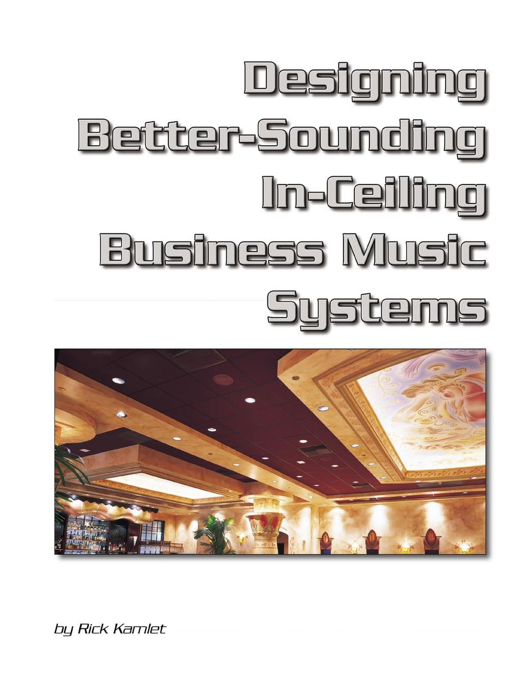
3 Part 1 Preparation, Objectives and Coverage A Well Designed Distributed Speaker System Greatly Enhances the Atmosphere of Business Spaces. Location: NIKE Goddess, Contractor: DMX Music BUSINESSES ARE RECOGNIZING MORE and more that top-quality sound is an integral part of a customer s experience. Studies have shown that sound quality affects how customers feel about the products and services in retail stores. Sound quality even affects customer perception of food quality and staff friendliness in a restaurant. Part of this trend stems from the fact that customers are more sophisticated about music quality than in the past. They have CD and DVD players at home and are accustomed to hearing good sound quality in their living rooms, in their cars and at the movie theater, making the demands on business venues higher than ever. Today, AM-radio-quality music is a business sound system blunder unless you sell antiques, perhaps. How do you put together a top-quality business music system? It may seem easier than it really is. We can t design systems the way we used to, using obsolete rules of thumb or just substituting a louder, low-quality sound for a quieter one and calling it a job well done. This paper assists in designing and setting up superior business music sound systems whether you are a new systems contractor or an experienced one. RESEARCH BEFORE DESIGN We have to approach each design analytically. The first step is to determine what the customer wants and expects. The questions you ask up front help you decide what kind of sound system to propose. DESIGN OBJECTIVES Before you start designing a business sound system, identify what the customer needs and expects: Fidelity Expectations. Does the client want a good, basic system; something a little better than average; or maximum bandwidth and maximum fidelity? Sound-Level Requirements. Will the system be used strictly for background music, or does it really need to rock? Usage. What kind of music will be played through it? For example, if it s urban funk, then you re going 3
4 to have to think about the bass quality and SPL capability. Form. Do they want in-ceiling or on-wall speakers? Coverage Requirements. How even do they want the coverage to be? Is it okay for it to perceptibly vary in volume within the space, or do they want it even throughout? Are there areas that don t need to be covered at all, or where they might want lower SPL, such as the cash register area in a store? Low-Frequency Coverage. How even does lowfrequency coverage need to be? If you re using subwoofers, is it okay to use a small number, meaning the sound will be loudest close to the sub(s) and softer elsewhere, or do the subs need to cover evenly? Paging. Do they need paging? If so, how important is paging intelligibility? Zones. How many zones need separate volume controls, different source controls or paging assignment? Benchmarking. Do they want this system in order to keep up with a key competitor? If so, this can give you a benchmark. Cost. Does the system they want fit into their cost requirements? If not, which functions can be adjusted to meet the budget, or is a budget reassessment advisable? Collect this information and confirm your understanding with your customer BEFORE you start designing. You ll have a much clearer idea of how to proceed when you know what your customer needs. As we start thinking about the design, we need to then translate our client s requirements into specific goals for coverage, sound levels and bandwidth. Once these requirements are identified, we can start thinking about loudspeaker and component selection, speaker layout patterns and speaker density. We need to be able to correctly commission the system after it is installed, ensuring proper settings and optimal performance. OBJECTIVES FOR ELECTRONICS Before we talk about loudspeakers, let s look at the functionality of the system controller (whether analog or DSP) to ensure that it has all the control functions and features required. Does it have the performance features to make the system sound really good? Does it sound equally good when the music level is low as when the music level is high? Are there features to keep the music at a pleasant operating volume? Is it easy to add a subwoofer either now or later for additional bandwidth? The system also needs to be easy to install and set up, and, possibly most important, it needs to be protected from the end-user accidentally messing it up. Moving on to power amplification, we won t know about the amplifier power requirement until we do the speaker design; but we can identify our preferred performance standard. In order to get excellent sound quality, you must use a good power amplifier. These days, it s becoming less acceptable to use the commodity-grade amplifiers of yesteryear. We re talking about the weakest-link phenomenon. If your amp can t hold up its part of the sound quality requirements, then performance and quality in the rest of the system will suffer. Accessories. Let s touch on volume control accessories. I m not a fan of speaker-level volume controls. It s much better, when possible, to control the volume at line level, before the amplifier. Speaker level controls typically use tapped auto-transformers (sometime called autoformers). Autoformers can do some strange things to audio quality. They can cause distortion. They can change the frequency response as they re turned up or down. It is difficult to find autoformer controls that handle as much power as a typical zone in a high quality system requires. When they saturate (which happens when more low frequency voltage is sent to them than they handle), they tend to saturate badly. Even though you might not ever hear the low-frequency content coming out of the speakers, the saturation it causes can trigger the current limiting circuitry on the power amplifier, which in turn causes distortion throughout the entire audio spectrum. Your best option when using autoformers is to highpass the system, which then at least partially negates your objective of high quality sound. If at all possible, use a controller that allows you to adjust the volume at line level, eliminating all these problems. Now, let s talk about loudspeakers! CEILING SPEAKER COVERAGE Have you ever heard, or followed, rules of thumb like space ceiling speakers as far apart as the ceiling is high or as far apart as the distance from the listener s ear to the ceiling? While they are simple to follow, they aren t very practical. The conditions upon which these rules were supposedly based the needs of commodity-grade systems just aren t what s required today. No hard-and-fast rule is going to apply 4
5 in all cases. You need to find out what the customer needs before you start making plans around speakers. The main objectives in deciding about the placement pattern and density of loudspeakers in a distributed system are covering the area effectively, providing sound that is audible and intelligible over the entire area, and making sure the system is capable of sustaining whatever sound pressure level the application requires. A Common Misunderstanding. The following misunderstanding about the coverage angle specification of loudspeakers can easily result in system design mistakes. First, let me clarify that the term coverage angle is the angle at which the sound level is 6 db down from the on-axis sound level. It is very common to see a polar coverage spec of the coverage angle on a spec sheet and assume that the speaker will actually cover this angle when installed. It seems like it would be the case, doesn t it? But the truth is that loudspeakers actually cover less area than their spec sheets would imply. Polar vs. Listening-Plane Coverage. There are two different types of coverage measurements that get confused for one another. It is standard in the loudspeaker industry to state the coverage in a polar pattern in a sphere that is 1 meter from the speaker in all directions. The angle where the sound level is down 6 db from the on-axis level is called the edge of the polar coverage pattern. This is what appears on spec sheets. It s a legitimate specification, but it does not represent what the coverage will be over a flat listening plane, as in any room, because it doesn t take into account the difference in distances that people are from the speaker. For speakers projecting from a ceiling onto a flat listening plane, the sound has to travel farther off-axis (to the sides) than it travels on-axis (directly below the speaker) resulting in a much greater dropoff of sound level off-axis. The result is that the actual coverage angle (at -6 db) on the listening plane is more narrow than the polar spec. Some ceiling speaker manufacturers use their polar measurement to claim extraordinarily wide coverage. Do not use this specification to lay out coverage patterns of ceiling speakers! The sound system designer needs to work with the actual coverage over a flat listening plane because that is the plane in which we live, listening at a height of 3 to 6 feet above the floor, depending on how tall we are and whether we re standing or seated. This is called the listening-plane coverage specification of the speaker. The listening-plane spec represents the reality of the speaker s coverage for the listeners. Laws of physics dictate that the listening-plane coverage is always more narrow than the polar coverage pattern. Figure 1 shows a speaker that has a 140 polar coverage (i.e., its 6dB down points). We can see that it would be a mistake to assume that this speaker can cover 140 over the listening plane. In fact, the level at the edges of a 140 pattern is actually more than 15 db down compared to on-axis not 6 db down. It s interesting to note that the same proportions hold true for any ceiling height: No matter how high the ceiling is, the off-axis distance is farther away by the same proportion. So for the loudspeaker in this example, whether the ceiling height is 8 feet or 20 feet, the listener who is at the edge of the 140 pattern, who you might have thought would be at the 6 db down point is really at the 15 db down point! Figure 1 The actual listening-plane coverage depends on the polar plot of each speaker. On average, the coverage of the listening plane from a speaker with a 140 polar coverage is usually between 90 and 110 (see Figure 2). To Illustrate, imagine a loudspeaker with a 180 polar spec. If you were to incorrectly interpret this as 180 coverage on the listening plane, then one speaker would be all you would ever need for any application. Imagine a single speaker trying to cover an entire department store or restaurant. In fact, you will see that unless a speaker can send more sound to the sides than it does directly on-axis, it never covers more than

6 Correction Factor figure from Table 1 for that angle off-axis to the figure from the polar plot. If you re doing this correctly, the coverage pattern is getting more narrow than the original polar plot. By using the actual polar plot of the speaker and applying these correction factors from the chart, the angle that results in a figure of -6 db is the angle of coverage for the speaker. This angle is the real 6dBdown angle for that loudspeaker when it is projected onto the listening plane. Remember that this coverage angle is valid regardless of the ceiling height. Figure 2 CONVERTING COVERAGE How do you convert polar coverage to listening-plane coverage as you design sound systems? There are two ways. One is to use a computer program that does the conversion for you. If you have a copy of EASE, place the speaker in the ceiling, set the listening plane height to the typical application height and see how much area it covers (at the 6dB down point). Usually that s enough, but you can also do a little bit of math and figure out what the real listening plane coverage angle of the speaker is. JBL Pro created a simple program, Distributed System Design, to do this same conversion for their speakers. I think there are some programs available that have a more generic database of speakers. The second way to compute the listening-plane coverage is to start with the exact polar plot of the speaker and use a conversion table. (Real polar plots directly from test equipment are more accurate than an artists redrawing.) Polar plots are usually normalized to the on-axis value, which is usually labeled 0 db. For every angle off-axis, there is a difference-figure between this normalized on-axis value and the volume at that angle. Table 1 To convert to listening-plane coverage, add the db Example 1. If we look at the polar plot of our hypothetical speaker with 140 polar coverage, we see that at 70 off-axis (140 total for both sides) the level is down 6 db compared to the on-axis level. By looking at the polar-to-listening-plane conversion chart, we need to add -9.3 db to this -6dB figure to find the actual level on the listening plane at this off-axis angle. We find that the level of this 140 speaker (as specified by the polar coverage) is actually db, not -6 db, down at 70 off-axis. Therefore, listeners located at this off-axis angle will hear sound that is more than 15 db down from the level they hear when they pass directly underneath the speaker. This is a very large difference. To find the actual 6dB down point of the speaker for the listening plane, take the actual polar plot of the speaker and at every increment of 5 off-axis, apply the correction factors from the polar-to-listening-plane conversion chart. The 6dB-down angle is that angle at which the new figure reads -6dB (polar db down plus the additional db down from the correction factor). While the final resulting angle depends on the actual polar plot of the speaker, it can generally be said that most speakers with a nominal polar coverage of 140 can be expected to reach -6dB between 45 and 55 off-axis, resulting in an actual listening-plane coverage between 90 and 110. Example 2. Let s look at a speaker that has a 180 polar coverage. Let s further assume that it is a mythical perfect speaker where the volume doesn t go down at all at any angle. Its polar pattern when placed in a ceiling is a perfect half-circle. To find the real 6dB-down point, we apply the correction factors and find that at 60 off axis (120 coverage), the sound is 6 db down (again, polar db 6
7 down plus the additional db down from the correction factor). Therefore, the real listening-plane coverage of a perfect 180 speaker is only 120. Now, given the fact that speakers with a spec of 180 polar coverage can actually be down as much as 6 db at the 180 point and still have a spec of 180, the fact is that virtually all speakers have a real coverage of less than 120. FURTHER FACTORS A couple of interesting points follow from this discussion. First, let me point out that subwoofers resemble Example 2. They have omnidirectional coverage of 180 (when in the ceiling). So they, too, have listening-plane coverage of only 120. Second, while it is not within the scope of this article, you can see that this principle applies to all loudspeakers projected anywhere. The fact that the listening plane in any venue is hardly ever a perfect sphere around the speaker means that you will almost always be projecting speakers onto a somewhat listening plane; and the coverage is almost always going to be more narrow than what the polar spec would indicate. A student once mentioned to me that he had done some church designs taking a protractor and scribing the coverage pattern onto the floorplan drawing. When the system was installed, they had more holes than expected. After a class on coverage, he realized that it is a matter of projecting a speaker onto a listening plane so that the actual coverage is going to be narrower than what he plotted. Some ceiling speakers specify their coverage only at a particular frequency, often at 2 khz. The reason 2 khz if often used is that 2 khz is the most important octave fr speech intellibgibility. However, other octaves a still very important for intelligibility and all octaves are important for music. Many types of speakers do not provide even coverage throughout the audio spectrum. Every spot within the listening area ends up with a different frequency response and different sound level (see Figure 3). In addition to this making it impossible to set a coverage angle, it also defeats attempts to equalize because whatever spot you choose to set your EQ, it s different everywhere else. But there is a good solution: Choose speakers that cover similar angles throughout a broad frequency range. This is one advantage of having speakers with small diameters (so they don t start beaming until a very high frequency), or having multiway speakers with goo crossover networks where higher frequencies are reproduced by small drivers (tweeters or compression drivers for high-power speakers). Hor,ns on the high-frequency drivers further help in providing even coverage at all frequencies. See Figure 4 for a well controlled speaker. Polar Coverage of Control 26C (Actual Coverage by Frequency) FREQUENCY COVERAGE Let s talk about broadband vs. single-frequency coverage specifications. You may have done all the conversion work above, and it might apply only to one frequency! If the speaker does not have similar coverage at all frequencies, then it covers wider or narrower angles at different frequencies. Figure 3 Figure 4 REVIEWING Let s take one more look at the old rule of thumb that says to space the speakers as far apart as the distance from the listener to the speaker. First, this rule was based on an incorrect assumption that all speakers covers 90. Even for speakers where this coverage is true for some frequencies, it may not be tru for all frequencies. In today s high-quality sound systems, you need to consider real coverage, not polar or incorrectly assumed coverage. 7
8 8
9 Part 2 SPL & Equalization We need to consider the real, long-term sound pressure level capability of today s systems to make sure they re not being operated at levels where the components are stressed or where they won t sound good. While acoustic design programs do a good job of predicting how the system will perform in a given room, the system designer must determine what the goal is for each application. WHAT SPL IS NOT SPL is not a substitute for fidelity! Have you ever been to one of those locations where management seems to think it is meeting today s need for higher quality music simply by putting in a louder sound system? Either your thoughts get drowned out in the barrage of noise, or the speakers sound awful because they re turned up beyond their capacity. SPL alone cannot make up for lack of fidelity. We need to consider the real, long-term SPL capability of today s systems. SOUND PRESSURE LEVEL Maximum SPL Capability. In the simplest theoretical terms, loudspeakers produce sound levels according to three factors: 1) the speaker s power handling capability (specified as driven with an industrystandard pink noise signal); 2) the speaker s sensitivity (the sound level produced with 1 watt of input power); and 3) the distance between the speakers and the listening plane. Power handling and sensitivity are generally provided on the speaker s spec sheet. [Note that JBL Pro includes a 2 hour and a 100 hour power spec on some loudspeakers. The 100 hour figure is for reliability testing. The 2 hour is the figure to use for these SPL computations.] Consider the distance from the speakers to be the ceiling height minus the listening-plane height (sometimes called ear height). It s common to assume that ear height for a seated audience is around 3.5 feet above the floor, and ear height for a standing audience is about 5 feet above the floor, on average. For every doubling of distance beyond 1 meter, subtract 6 db. Maximum SPL Formula for Pink Noise -- The formula for computing maximum SPL capability for a pink noise signal is: M ( pink ) = S + 10(log P ) - 20(log D ) where M ( pink ) is maximum average SPL for pink noise, S is SPL from sensitivity, P is pink noise power handling and D is distance in meters The SPL Adjustment for Music and Speach -- This resulting SPL for pink noise figure, even at the standard 1-meter distance, is not a measure of the typical music or speech that can be expected from the system. Pink noise is different from music and speech. A downward adjustment of at least 4 db must be made to the maximum pink noise computation to reflect the maximum average SPL capability for music or speech. Why does a 4dB adjustment need to be made? Pink noise has a peak-to-average ratio of 6 db. In other words, the average signal is only 6 db lower than the peak signal. Music or speech, on the other hand, has a peak-to-average ratio of at least 10 db. If we keep the peak capability at the same point as where it has been tested with the pink noise, then average music or speech is 10 db below that (or 4 db below the pink noise s average level). Take the pink noise rating and lower it by at least 4 db to get the maximum SPL capability for music or speech. Voila! Notice that this adjustment factor is based on an assumed 10dB peak-to-average ratio. I use 4 db as the highest average music or speech will be able to attain. You may choose to make an even bigger adjustment, maybe -6 db or -10 db, corresponding to peak-to-average ratios of 12 db or 16 db. Adjusting our formula, the maximum SPL of music or speech of a single loudspeaker is: M ( music or speech ) = S + 10(log P ) - 20(log D ) - 4 where M ( music or speech ) is maximum average SPL for music and speech, S is SPL from sensitivity, P is pink noise power handling and D is distance in meters SPL Capability of Multiple vs. Single Speakers. One other thing to consider is that the SPL capability of a multispeaker system is higher than that of a single speaker because multiple speakers overlap to a degree that depends on their layout and spacing. This will be discussed more later. SPL of 70V/100V vs. Low-Impedance Speakers. Speakers with 70/100 volts produce lower output SPL than do low impedance (4-, 8- or 16-ohm) speakers. This is because, first, 70/100-volt speakers are typically tapped at lower power levels than the lowimpedance speaker s maximum capabilities. Second, 9
10 there is always some insertion loss through the speaker transformer. Possibly the biggest factor, though frequently overlooked, is that the driving amplifiers clip at 70 volts (on a sine wave). The highest the audio signal can get before clipping is 70 volts (or 100 volts outside the United States). The average for music or speech is at least 10 db below that. So, if you re tapped at 15 watts, you re really only averaging somewhere around 1.5 watts of sound out of that speaker, and that s with the peaks hitting clipping! If you compute SPL based on the mistaken assumption that you get a continual 70 volts going into the speaker, your estimate is going to be at least 10 db higher than the real average music or speech that can actually come out of that speaker! Power Compression. Speakers compress sound at high volumes. As their voicecoil temperatures rise, the impedance of the voicecoil goes up, resulting in less draw of audio power from the same voltage drive signal. This is called power compression. We have left power compression out of the formulas because speakers differ in this regard, and because the degree of compression is highly dependent on operational factors such as the peak-to-average ratio of the signal source. Power compression is also affected by the degree to which the speaker is being run below its maximum capability. You can generally assume around 2 or 3 db of compression for quality speakers (such as those with large diameter voicecoils) with typical music or speech; and assume as much as 5 or 6 db of compression with inexpensive speakers (especially those with small diameter voicecoils and/or low power ratings), operating with compressed music sources. SETTING SPL TARGET GOALS While the JBL DSD Distributed System Design software, acoustic design programs (like EASE), and computerized programs from other manufacturers do a good job of predicting how the system will perform in a given room, the system designer must determine what the goal is for each application. The following is intended to help set an SPL goal for the system design. For systems requiring paging intelligibility, here are some general guidelines to use as starting points in your system designs. The SPL levels we re considering here correspond to the maximum average SPL for music and speech (which, you ll recall, is at least 4 db lower than the maximum average SPL for pink noise). Factors to consider include the ambient noise, loudspeaker distance from listeners, loudspeaker overlap, the type of program material and fidelity expectations of the listener. Determining SPL Above Ambient. Economy background music installations require an average music level capability of at least 5 db above the ambient noise. For good paging intelligibility, the system needs to be 10 db higher than the ambient noise. Levels of 15 to 20 db above ambient yields excellent intelligibility. (See Table 2.) +5dB +10dB dB Economy background music only Good paging intelligibility and music quality Maximum intelligibility and highest dynamic range Table 2: Average SPL targets above ambient noise level. Finding the Ambient Sound Level. If the installation is in a location that is already in use, use an SPL meter set for slow response to measure the A-weighted ambient sound at the listener s ear position. Take measurements during the noisiest time and make sure the HVAC (air handling) system is operating during the test. If the installation will be in a new facility, try measuring the ambient sound level in a similar type of venue. Determining An Absolute Sound Level Goal. If the ambient sound level is low, then it s possible that paging will still not be intelligible, so here are some guidelines. For those not used to working with decibels, keep in mind that movie theaters are calibrated such that 85 db is the level of the dialog when you re sitting 2/3rd of the way back in the theater. In the absence of background ambient sound, 85 db is a good goal for excellent paging. If people can understand dialog in a movie theater, they can understand a page at that level. 75 to 80 db is often acceptable for paging. Below 75 db and it starts getting difficult for some members of the population to hear or understand the page. DESIGNING FOR SPEECH INTELLIGIBILITY Choose the Appropriate Speaker for Output Capability. Make sure the speaker you choose has adequate power handling and sensitivity to produce the sound levels required. For good paging, the speaker is typically required to sustain average speech levels that are at least 10 db higher than the ambient noise level. Cover Mid and High Frequencies. Choose a speaker with the appropriate coverage pattern for your application. For intelligibility, select a speaker that has especially even coverage in the 1 to 6kHz range. Power the Speaker Adequately. Make sure the speakers are driven with enough amplifier power to sustain the expected sound levels. It doesn t help to have speakers with enough output capability if you don t provide enough amplifier power to drive them to that capability. Clipping the power amplifier adds considerable distortion, degrades intelligibility, and 10
11 results in unacceptable sound quality. Clipping is hard on the speaker and can cause damage and failure. EQUALIZING CEILING SPEAKERS Setting EQ for ceiling speakers can be different than with sound reinforcement speakers. Incorrect measurement techniques will result in the system not sounding very good. It would be a shame to design and install a great system and then misadjust the EQ so it sounds like an amateur job. An example of poor measuring technique is positioning the measurement mic in the overlap region between adjacent speakers. This can lead to faulty measurements. Microphones tend to show signal additions and cancellations at various frequencies that only occur in that one-inch space where the microphone is placed and may not be representative of the listening space as a whole. More than a few installers have tried to equalize for floor reflections, which sometimes results in large boosts and cuts in adjacent EQ filter bands. You can not equalize out floor reflections (or any other reflections). For good, solid measurements, here are some suggestions: Mic Placement Within the Speaker Coverage Pattern. Place the microphone either on-axis or up to 20 offaxis. Try to stay within the coverage pattern of a single speaker. When equalizing on-axis, you are equalizing the direct sound in the mid to high frequencies, whereas at low frequencies, you re still taking into account the low-frequency summation of adjacent speakers. Mic Height. While it seems like it would be best to place the microphone at the typical listening height for the application, the measurements can be contaminated by floor reflections that can artificially add or subtract to various frequencies as displayed on your test equipment. For example, a measurement taken at a 4-foot (1.2-meter) height may show dips at odd multiples of 80 Hz (240 Hz, 400 Hz, 560 Hz, 720 Hz, 880 Hz, etc.) and peaks at even multiples of 80 Hz (160 Hz, 320 Hz, 480 Hz, 640 Hz, etc.). Depending on the resolution and bandwidth characteristics of your measuring device, these can show up as various boosts and dips in your measurement bands. These reflections are not equalizable, and trying to equalize them out can result in a very bad sounding system. It is best to eliminate floor reflections from your measurement. How do you do that? Eliminating Floor Reflections by Mic Positioning. To eliminate the floor reflection from your measurements, use the microphone in pressure zone mic mode by placing the mic on a hard surface on the ground or by setting it on a large piece of plywood at ear height. For this type of measurement, the microphone is typically laid on its side. If you re using plywood, place the mic slightly off center on the plywood to minimize complications from the addition of symmetrical diffraction effects from the edges of the plywood plane. Placement about 4 to 6 inches away from the center point, toward one of the corners, is appropriate. To maximize the high frequency accuracy, make sure that the microphone diaphragm is as close to the plywood plane (or floor) surface as possible. If the natural contour of the mic case makes the element sit off the surface, it is beneficial to angle the case so the mic diaphragm is within ¼ inch (6 mm) of the wood surface, without actually touching the wood (or floor). You may get some strange looks by placing your microphone on the floor, but it s the best way to get an accurate measurement. Anyway, funny looks during the testing phase sure beat funny looks after the system is up and running. Microphone Type. If possible, use an instrumentationgrade microphone. To get the most accurate measurement in PZM mode, a small-diaphragm mic with small housing is best because it allows the mic diaphragm to get as close as possible to the plywood (or floor), minimizing any interference between direct waves and those reflected back onto the diaphragm from the plywood itself and thereby minimizing false information. Your curve is only going to be as good as the measurement mic you re using, so if at all possible, use an accurate, top-quality instrumentation mic. EQUALIZATION It is often best to adopt the strategy of only cutting the EQ filters, never boosting them. Peaks in the frequency response can be more bothersome and can be equalized out. Dips in the frequency response tend not to be as audible and because they are frequently caused by time-related phenomena, they are often not equalizable. So it s usually best not to bother with equalizing out the dips in the frequency response curve. A graphic EQ with only a few bands is probably not of much use in EQing a system. In order to remove the peaks, you end up taking out way too much good sound content. Note that as with graphic EQs, you must be wary of large boosts and cuts in adjacent filter bands. Use equalization gently. More and more DSP-based business music controllers now include parametric EQs, which are often more useful than graphic EQs because you can really pinpoint the frequency required and narrow the filter enough to take out only as much as needed without 11
12 taking out too much content. Do not try to equalize reflections -- even those that show a peak at your measurement position -- because they change with every mic position in the room. If you re not sure what s real, move the mic to a number of locations and see what peaks are common to all locations. I like to set the EQ for a gentle roll-off of high frequencies. A roll-off of somewhere around 3 db, starting at 2 khz per octave (4 khz being down 3 db) often sounds better than setting it flat. Guard against the common computational mistake of assuming that you ll get the SPL you computed at 70 volts from a 70 volt system. After the installation, be sure to EQ the system with the right microphone setup, avoiding some of the common EQ mistakes mentioned above. For bass frequencies, you may have to experiment with what sounds best for that application. You might need to set the bass frequencies (below 90 Hz) up as much as 10 db higher than the mids and highs in order to balance the sound. Be careful not to boost bass frequencies that the speaker can t handle. Ported speakers can t handle their full rate power below their tuning frequency, so find out from the manufacturer what frequency the loudspeaker is tuned at, and make sure not to send it frequencies lower than what it was built to handle. One factor affecting how much higher to set the bass (compared to the mids) is how loud the system will be played. Unfortunately, music itself goes up and down in level, so the balance is going to be wrong at some music levels. Unless you ve got a dynamic system that automatically adjusts for this (such as the Autowarmth function on JBL s SoundZone controllers and some DBX zone controllers), you re probably going to need to just split the difference and set the bass volume somewhere between the loudest and the softest musical volumes. REVIEWING Now you know some key steps in putting together a top-quality business music system. So, let me summarize a few key points: Lay out the system based on the real coverage as projected onto the listening plane don t base it on the polar coverage specification from the spec sheet. Help customers avoid the assumption that a loud sound system is necessarily a good sound system. Design a system that has the real SPL capability that s going to be required, without distorting or becoming harsh. Don t assume that the computed pink noise capability of a system is what they re going to be able to get with music or speech. 12

13 Part 3 Speaker Layout Properly Spaced Distributed Ceiling Speaker System in Restaurant, Painted to Match Ceiling. Location: Cheesecake Factory Restaurant. Installer: TAB Technical Services. Cover Photo. Hexagonal Pattern In a hexagonal layout pattern, the rows are offset from each other. While a hexagonal pattern typically uses more speakers, it may use fewer in some particular cases. For example, in a room laid out with a square pattern, it the end row of speakers cover only a small area. In a room where the width is 1.5 times the coverage of the speaker, part of a speaker s coverage is wasted in the square pattern. In these cases, you might be able to reduce the number of speakers in each row by one and offset the rows from each other, with the offset speaker from one row partially filling in the uncovered area from the adjacent row. This sometimes can reduce the evenness of coverage, however. I recommend using the square pattern when possible. S quare Layout Pattern Hexagonal Layout Pattern SPEAKER LAYOUT PATTERNS A number of different patterns can be used for laying out ceiling speakers, and each pattern can be implemented in different degrees of layout density. The pattern and density selected for an installation affect the: Evenness of coverage Sound level capability of the system Intelligibility Power amplification requirements Cost of the system The two basic, most widely used speaker patterns are square and hexagonal (also called offset or triangular). Square Pattern A square pattern lines up the rows and columns and often requires fewer speakers, resulting in a lower system cost. A square pattern is easy to lay out, especially on a suspended ceiling tile grid. It may also be easier for zoning large open spaces. It is usually the preferred choice, delivering more even coverage, and often with fewer speakers. It s usually the best starting point for a design. Figure 4 SPEAKER DENSITY The three most common densities in speaker layout are edge-to-edge, minimum overlap and full overlap. Edge-to-edge density places the speakers such that the outside edges of their single-speaker 6dB down points (as projected onto the listening plane) just touch one another. Minimum overlap is a tighter spacing where all spots are within the 6dB coverage pattern of at least one speaker. Full overlap is tighter still: the 6dB down point of one speaker extends to the on-axis point of adjacent speakers, and all listeners are within the coverage pattern of at least two speakers. See Figure 4. Considerations for Selecting Layout Density In general, higher speaker density increases the SPL capability, overcomes ambient noise better, and reduces the variation in sound level throughout the space. 13
14 Budget may necessitate an edge-to-edge spacing when a higher density would be desirable. In this case, the designer should inform the client of the ramifications before the system is installed. Higher Sound Levels (SPL) Tighter speaker densities allow for slightly higher SPL levels due to a greater number of speakers covering each area within the listening space. While the summation between adjacent speakers is incoherent, there is still some increase in SPL. See Table 3. Level Variation Due to Layout Density The speaker density also affects the amount of variation of the sound level within the listening space. The tighter the spacing, the more consistent the sound will be from place to place. Some off-axis locations will be lower by as much as the stated figure in Table 3. For example, in a square pattern installation with edge-to-edge density, if the on-axis maximum SPL for music and speech (considering distance from the speaker and any additional SPL from layout density) is computed to be 92 db, there will be some locations within the listening space that will be 4.4 db lower at 87.6 db. Pay attention to level variation in a distributed system s design. Don t assume that every location within a listening space will be at the same level or achieve the same SPL as directly under a speaker. CONSIDER THE ENVIRONMENT Audience Mobility Seated audiences, as in a restaurant, can be bothered by excessive level variation throughout the space. One table might be disturbed by high sound levels while another can t hear the music or paging. In applications where the listeners move around, there may be more tolerance to variations in coverage. High Ceilings For high-ceiling applications, it is often best to select a speaker that has somewhat narrow coverage. These tend to have higher sensitivity, allowing the sound to be more focused as it travels the distance from the high ceiling to the listening plane. In high-ceiling applications, you don t want to hear mids or highs from speakers on the other side of the room. That adds to the reverberant noise field, degrades the intelligibility of speech and interferes with the coherence of music. If the ceilings are high and the room is large, severe intelligibility problems can develop. You shouldn t hear very much sound from any speaker whose path length to your ear is more than 30 feet longer than that of the closest speaker. The human aural system tends to integrate sounds that are heard within 30 milliseconds of each other, but sounds that are more than 30 milliseconds apart interfere with each other. To avoid this, it is simply best in high-ceiling applications to use narrow-coverage speakers. Spacing is a subtle art, but there are some guidelines. In a fairly dead room with low ambient noise and a relatively low SPL requirement, an edge-to-edge pattern will often suffice. In a room with a lot of reflective surfaces, high ambient noise and a paging or sound reinforcement requirement, minimum or full overlap is probably indicated. Full overlap should be used when a very high-quality sound reinforcement system is critical. Increase in SPL Compared to a Single Speaker SPL variation within listening range Square Pattern Full Overlap +5.2 db -1.4 db Minimum Overlap +2.0 db -2.0 db Edge-to-Edge +0.7 db -4.4 db 1.4 Edge-to-Edge +0.4 db -6.8 db 2 Edge-to-Edge +0.2 db db Hexagonal Pattern Full Overlap +5.4 db -1.2 db Minimum Overlap +1.4 db -2.6 db Edge-to-Edge +1.0 db -5.4 db 1.4 Edge-to-Edge +0.5 db db 2 Edge-to-Edge +0.3 db db Table 3: SPL increases and variations by ceiling speaker density and pattern.
15 a) Edge-to-Edge b) Minimum Overlap c) Full Overlap a) Edge-to-Edge b) Minimum Overlap c) Full Overlap
16 16
17 Part 4 Subwoofers Now, let s turn our attention to an element that can mark the difference between good and great business music systems: subwoofers. Bump Zone Resulting Frequency Response Subwoofers are an important part of an outstanding business music system. Light background or foreground music might not require subwoofers; however, even in systems where the bass doesn t need to be a dominant factor, having clean, full low frequencies can make a big difference in the customers enjoyment of the music. The number of subwoofers to use, where to position them, how to set the taps (on 70V/100V subs) and how loud to run them vary depending on the characteristics of each installation. Criteria such as speaker placement, boundary loading (are speakers placed close to a wall or in a corner?), size of the room, coupling of multiple speakers/subwoofers, reverberance of the room, the type of music, the type of activity and the expectations of the listeners all come into play. The following guidelines are given, therefore, in very general terms. CROSSOVERS The four ways to cross over to a subwoofer are: Passive crossover, which is usually built into the subwoofer Acoustic crossover, such as a bandpass box that is acoustically filtered not to reproduce high frequencies Active crossover, which may be a separate electronic device or can be built into the subwoofer or a controller a combination of these, such as using a bandpass box with an active crossover. In addition, there are two main topographies for crossing over: overlap crossover, where the main speakers are run full range and the subwoofers are just added to them; and full crossover, where the subwoofer covers the subwoofer frequencies and the main speakers are high-passed to cover the rest. (See Figure 6.) You need to decide on a system topography the way you re going to cross over the system before you can figure out the quantity of subwoofers needed. Let s talk for a moment about the options. SPL SPL Frequency Frequency Figure 6 Full Range Speaker Subwoofer Resulting Frequency Response High Passed Speaker Subwoofer OVERLAP CROSSOVER In an overlap crossover, the main speakers are run full range, and the subwoofers just add to the bass frequencies. An overlap crossover can be accomplished either with a built-in passive crossover or with an active crossover. The advantage of using an overlap is that it sometimes allows you to use fewer subwoofers. The BIG downside of this topography is that the main speakers usually only go down to 80 Hz or so, and the subwoofers often have a response as high as 160 or 200 Hz. (Hopefully, the subwoofers are internally low-passed with a passive crossover or they re limited by being a bandpass design.) Even if the subwoofer only goes up to 120 Hz, you re often in trouble. The problem is the overlap band. Between 80 Hz and, let s say, 160 Hz, both the mains and the subwoofers are reproducing, whereas below that range it s only subs, and above it s only mains. Thus, you get much higher sensitivity in this low-to-midrange band. You end up with a big bump in this mid-bass range, which is often perceived as muddiness. Don t mistake loudness for fidelity, is a good adage here. An overlap-crossover system might get loud but 17
18 fall far short on the fidelity scale. The business might comment that the subwoofers don t seem to get very low because you re emphasizing the mid-bass range. You can add more subwoofers until the cows come home, but it will only get muddier. To compensate for this effect, you need to include a good EQ to notch out the bump. A single parametric band can often do it. It s difficult with a graphic EQ of less than 31 bands. Even a 15-band graphic can take out too much good stuff along with the bad, unless the frequency and bandwidth happen by chance to match your bump precisely. Certainly, 7-band EQs are of little use with this kind of overlap bump. While an overlap crossover might allow you to use fewer subwoofers, unless you re including a really good EQ, an overlap tuning in a business application is probably not advisable. Another way of dealing with this is to use an active crossover on the subwoofer so you can slide down the subwoofer s low-pass frequency to reduce the mid-bass bump. While that will help a lot, it can be difficult to match the electronic low-pass characteristics of the subwoofer band with the acoustic low-frequency roll-off of your main speakers. Adjusting the low-pass frequency is usually a big improvement from the passive overlap bump, but you can still end up with some abnormalities at and below the crossover point. FULL CROSSOVER A full crossover high-passes the main speakers and low-passes the subwoofers. The result is a nice, smooth transition. A full crossover almost always sounds better than an overlap, but since the subwoofers have to cover the bass frequencies all by themselves, you will probably need to use more of them. You can accomplish a full crossover either passively or actively. Full Passive Crossover Passive systems usually use crossovers built into the subwoofer. The full-range amplified sound goes to the subwoofer, where the lows are sent to the subwoofer driver. The main speakers are connected to the satellite output, which sends them mids and highs (with the bass removed). This works alright, but the crossover components need to be large (to handle the low frequencies), and they eat up some of your power. The crossover slope is usually not very steep, around a 12 db per octave low-pass to the sub and a 6 db per octave slope to the mains, or satellite speakers. Steeper high-pass slopes are typically avoided because they can self-resonate or cause strange impedances to the amp if a satellite speaker doesn t get connected to it or if the satellite speaker blows during use. However, with a firstorder (6 db per octave) passive high-pass crossover (for the satellite speakers), the crossover frequency changes with the impedance that is connected. The higher the impedance load, the lower the crossover frequency. An output that works properly with a 4-ohm load as with two 8-ohm speakers will be too low in frequency if you only connect a single 8-ohm speaker, leading again to an overlap bump because of misadjusted crossover frequencies. Sensitivity Balance Issues. The biggest potential problem of a full passive crossover is that you re at the mercy of the sensitivities of the subwoofer speakers versus that of the satellites and the need to properly balance the volume of each. The subwoofer might have a sensitivity of 89 db, while the full-range speaker might have a sensitivity of 92 db. In business applications, because of the low volumes, the bass often needs to be between 6 db and 10 db louder -- not quieter nor even equal in volume -- than the satellites in order for the system to sound balanced. In passively crossed systems, the subs are often softer than the mains, and that s a problem. The fix? Well one fix is our friend the high-resolution EQ that can pinpoint and boost the exact frequency where the volume drops. A standard bass control (shelving type) is usually not a good solution. The chance that any standard bass control will match with the exact frequency, slope and shelving characteristics that are needed by any particular system are slim. It is difficult enough for engineers to design a good passive crossover when they know the exact characteristics of every component in a single cabinet. With a business music system, you ve got so many variables sensitivities, roll-off characteristics, number of speakers, placement, boundary loading effects, etc. that it is difficult to get a passive crossover to work well. Although a well-done full passive crossover can sound quite good, it s much easier to wind up with one that sounds pretty bad. Full Active Crossover Full active crossover is the most reliable way to get a good subwoofer sound. This means using an active crossover and a separate power amplifier for the subwoofer(s). The subwoofer gets low-passed using a steep slope, usually 24 db per octave, and the mains get high-passed with a steep slope. They interact in predictable ways. There is virtually no overlap between the subs and the main speakers. There is no booming overlap bump like you get with the overlap crossover. You get independent control over the bass volume so you can easily balance it with the mains by ear, or via an SPL meter. If the customer doesn t like the balance, you can easily adjust it. 18
19 There are business music controllers that include a subwoofer crossover built right into them, like JBL s Soundzone controllers, dbx s ZonePro controllers, Crown USM, BSS ProSys and others that are on the market. SPL AND FREQUENCY RESPONSE Let s delve a little more into the SPL requirements for subwoofers. Typically the goal for subwoofers is to be somewhere between 2 and 10 db louder than the main speakers in the system. Low- and medium-level music requires subs to be louder than the main speakers because at low sound levels the human ear needs more bass for a perception of wellbalanced sound. Given the same music, higher levels of music can sound well balanced with less relative bass increase. There are also some music types and applications, like dance music in upscale fashion retailers, that may require more than +10 db of bass. Setting the ratio of subs to main speakers somewhere between +2 db and +10 db, as measured by a flat SPL meter, is usually a good starting point. As for subwoofer frequency response, especially for business applications, you probably don t want the subwoofer to go much below 40 Hz. Below that, you end up with bothersome rumble, which can build up in corners or at room-mode nodes (function of a room s dimensions). Rumble can annoy customers. They might not be conscious of it, but when they re standing near the corner of the room, looking at clothing on a rack, low-frequency rumbling can make them uncomfortable enough to chase them out of the store. If a customer says they don t want subwoofers because they heard subs at the XYZ Store where the subs were bothersome, then there is a good chance that XYZ Store s system installer made the mistake of putting in too much rumble below 40 Hz, or left in a mid-bass bump because of an overlap crossover, or used a passive crossover that doesn t work correctly with the selected product mix. The list of pitfalls goes on, but if it s well-implemented by a skilled contractor, a business music system with subwoofers can sound absolutely wonderful! SUBWOOFER POSITIONING So how many will you use, where will you put them, how will you arrange them, and how will they relate to the mains? Effect on SPL Hanging a subwoofer in the middle of a room results in the lowest possible output from the subwoofer. Placing a subwoofer at the ceiling, wall or floor increases its output. Placing it within a few feet of a 2- boundary junction (like a ceiling/wall junction or a wall/ wall junction) increases its output further. Placement within 3 feet of a corner increases its output still more. In these cases, there is both an increase in sensitivity (output per watt of input) and in maximum total SPL capability. This can help in getting as much sound as possible from a few subwoofers. However, there is a potential pitfall in placing a subwoofer in a corner: You can wind up with uneven bass coverage in the room. Achieving Even Coverage In most installations, there are a lot more satellite speakers than there are subwoofers. Because there are often so few subwoofers (maybe only one), you can have a problem getting even coverage of the space. People sitting or standing very close to the subwoofer are going to get blown away with lows while people who are father away might not be getting enough. How do you make the subwoofer coverage as even as possible? As you move farther from the sub, the volume drops off, typically at 6 db per doubling of distance. Then, when you reach a certain distance, the subwoofer level stops dropping off at such a high rate. This is called the critical distance, which is where the reverberant field within the room equals the direct sound from the subwoofer. (See Figure 7.) SPL Room Reverberant Level Figure 7 (Critical Distance) Distance from the Subwoofer Overall SPL The critical distance depends on how reverberant the room is. As you get farther past critical distance, even though the level of the subwoofer doesn t drop off nearly as quickly, the quality of the subwoofer sound might not be as good. Even though this may happen, it s sometimes acceptable for subwoofers in business music applications. One way to make the subwoofer coverage as even as possible is to use more than one. It s a myth that all you ever need is one subwoofer. In many places, it s a good idea to add a second subwoofer, or more. Even if you don t need additional subwoofers for volume reasons, you might want to consider them just for evenness of subwoofer coverage. If I absolutely have to use just one subwoofer, my personal preference is to sacrifice the sensitivity increase and place the subwoofer for most even coverage, as long as I can achieve the SPL goals. 19
20 Placing Two Subs In systems with two subs, it is often best to place them asymmetrically within the room. In other words, if one sub is in the middle of a wall, try to avoid placing the second sub in the middle of the opposite wall. Small-room acoustics can cause interactions between subwoofers to create places where the bass builds up and other places where the bass cancels out and disappears. The topic of room modes is a paper in itself, but for now it s important to realize that, while there is not much you can do about room modes, you can minimize their effect with conscious subwoofer placement. If you place both subs symmetrically (on opposite walls), they will excite the same room modes in the same way, making disparities worse. If you place the second sub in a different position, it will tend to excite the room modes in a different way, and this is usually better. It s also good to know that placing the sub in the corner, while it does excite room modes, usually results in fewer mode bumps as compared to mid-wall placement. My experience when using two subs has been that one goes in the corner and the other goes close to, but not in, the opposite corner, about 10 feet out along one of the walls. Ratio of Subwoofers to Main Speakers The subwoofer is usually required to put out more power than the main speakers, so you might need more of them than you had guessed. You re not going to get much bass if you re using 20 full-range speakers at full power and only one or two subwoofers of the same power rating as the main speakers. Picture a three-way home stereo speaker in your mind. It has a 4-inch midrange driver and a tweeter. What size bass driver would you expect that one speaker would need to keep up with the midrange and highs? You re probably picturing an 8-inch driver, or even a 10- or 12-inch one. That s to balance a single 4-inch midrange! Now imagine a sound system with twenty 4-inch midrange drivers. You re going to need several 8-inch subs, or a couple of 12-inch drivers, plus a lot more power handling capability. Note too that the full crossover mode requires more subwoofers because the subs are carrying the low-frequency load by themselves; but, again, it results in the best overall sound quality. The ratios in Table 4 are no more than rough guidelines intended as starting points. The system designer needs to compute the SPL capability and determine that it will meet the user-expectations for the application. Note that the chart assumes the speakers are all installed in the ceiling away from wall and corner boundary surfaces (not getting the bass reinforcement from these boundary surfaces) and that if they are Overlap Crossover Mode Subs to Lower-Sensitivity Satellite Speakers Table 4 Subs to Same Sensitivity Satellite Speakers Ambient Bass 1:8 1:4 Medium Bass 1:4 1:2 Heavy Bass 1:2 1:1 Full Crossover Mode Ambient Bass 1:4 1:2 Medium Bass 1:2 1:1 Heavy Bass 1:1 2:1 70V/100V models, that both the mains and the subwoofers are tapped at their highest settings. You can scale up or down from there. For example, if you re tapping the main speakers down two taps (usually this means they re down 6 db) then you can reduce the number of subwoofers from what is suggested. Also, if you re placing the subwoofers in or near corners (around a 6dB increase in sensitivity) you can reduce the number of subwoofers. In addition, we re assuming certain sensitivity and power handling capabilities that may need to be changed for your installation. The subwoofer module in JBL s DSD Distributed System Design software asks a bunch of these questions and then computes the proper number of subwoofers for the system. Distributed Subwoofers If you are using in-ceiling subwoofers, remember (from Part 1 of this paper) that the subwoofer coverage projected onto the listening plane only covers 120. If you re concerned about having even coverage throughout the room, determine how many subwoofers you need based on approximate coverage of 120 per subwoofer. CONGRATULATIONS! You can now consider yourself an expert on business music system design! As I mentioned earlier, there are several computer programs that can help you with the design process. JBL s free utility called Distributed System Design does the polar-to-listening-plane conversions, computes how far apart to place the speakers, computes how loud the system can get with music or speech (taking into account the overlap factors), tells you what the sound level variation will be throughout the room based on the layout pattern and density, calculates how much amplifier power the system 20
21 needs, and calculates the number of subwoofers (if subs are being used). While this particular program is only set up for JBL speakers, there are utilities out there that handle other models. But even the snazziest software won t help until you determine your goals and your client s goals for the system. That will tell you whether you ve succeeded. Success is completely within your reach. A well-designed, properly installed, wide-bandwidth, low-distortion business sound system can create an outstanding space that customers will enjoy and that will improve the business image and ultimately their sales. 21

22 JBL Professional 8500 Balboa Blvd. P.O. Box 2200 Northridge, CA U.S.A. Part # DBS_BMS_GUIDE
What is Room EQ Wizard (aka REW)?
?") What is Room EQ Wizard (aka REW)? REW is room acoustics analysis software for measuring and analyzing room and loudspeaker responses, and is very handy for measuring the sub response in your room. It is
What is Room EQ Wizard (aka REW)? REW is room acoustics analysis software for measuring and analyzing room and loudspeaker responses, and is very handy for measuring the sub response in your room. It is
Distributed System Speaker Spacing for the Integrator
 Rev. March 20, 2018 Distributed System Speaker Spacing for the Integrator by Joe Ging, E.E. 2015 Lowell Manufacturing Company 100 Integram Drive, Pacific, Mo. 63069 USA (636) 257-3400 www.lowellmfg.com
Setting Speakers to Large or Small in Your Receiver or Pre/Pro
 Setting Speakers to Large or Small in Your Receiver or Pre/Pro We don t mean to sound like the Large or Small Police, The Setup Sheriff or Bass Management Mavens in this newsletter, but the information
As we survey audio systems
 -a five-part article in Home Theater magazine, October 1993 - February 1994 Home Theater Acoustics Volume Four Ambiance speakers are readily becoming standards in home theater BY ARTHUR NOXON As we survey
BI-AMPLIFICATION. To bi or not to bi. by John F. Allen
 BI-AMPLIFICATION To bi or not to bi by John F. Allen In recent years the technique known as bi-amplification has received quite a bit of attention. Conventional two-way speakers are two wire speaker systems
The ISP Technologies Advantage
 The ISP Technologies Advantage The ISP Technologies engineering team has been designing cutting edge audio products for more than 25 years and our engineering technology surpasses even the biggest and
2-Way Center Channel
 C2 2-Way Center Channel Table of Contents Introduction General Information Check Speaker and Parts General Care of Your Loudspeaker and Amplifier Bass and Loudness Contour Controls C2 Location Stands Speaker
Table of Contents. Introduction. General Information. Speaker Information S4X Crossover Wide Angle Phase Alignment
 Table of Contents Introduction General Information Check Speaker and Parts General Care of Your Loudspeaker and Amplifier Bass and Loudness Contour Controls S1.8Td Location Carpet Spikes Speaker Wire Speaker
STILL DON T WORK BY JOHN F. ALLEN
 WHY SURROUND SYSTEMS STILL DON T WORK BY JOHN F. ALLEN Non theatrical options for viewing motion pictures keep getting better. Sales of home theatre systems remain strong while attendance at movie theatres
Loudspeaker s frequency response was measured in-room, using windowed MLS techniques. The 0.5m set-up and results are presented on the pictures below.
 Rear Loudspeaker Transducer Measurements Loudspeaker s frequency response was measured in-room, using windowed MLS techniques. The 0.5m set-up and results are presented on the pictures below. Tweeter frequency/phase
MiniCube. When Used In Theaters. Performance. Dimensions. When Used For Distributed Audio. Predictive Placement. 6" wide. 8-1/2" deep.
 MiniCube Dimensions 3/8 x 16 insert accepts OmniMount 20 Series brackets. 6" wide Predictive 8-1/2" deep 9-1/2" SPL How loud will one speaker play, in db, with given amplifier power. Amp Power 3' 6' 12'
BI-AMPING THE ACOUSTIC ENERGY 120 SPEAKERS
 BI-AMPING THE ACOUSTIC ENERGY 120 SPEAKERS Introduction As Rod Elliott explains eloquently, bi-amping is a highly benificial way to drive speakers. Although nothing new, real bi-amping is still not the
EXPERT SERIES. A Diagrammatic Guide to Home Theater In-Ceiling Speaker Placement
 EXPERT SERIES A Diagrammatic Guide to Home Theater In-Ceiling Speaker Placement A DIAGRAMMATIC GUIDE TO HOME THEATER IN-CEILING SPEAKER PLACEMENT This diagrammatic guide of where to place in-ceiling speakers
o Rear HVAC columns (Priority 1: Item 3) the rear ceiling area: be more dead for the organ and traditional music. (Priority 2: Item A)
 the rear ceiling area: be more dead for the organ and traditional music. (Priority 2: Item A)") Table 2. Prioritized recommendations for sound system enhancements and acoustical finishes. PRIORITY SOUND SYSTEM ACOUSTICAL FINISHES Scheme 1: Priority 1 Priority 1: Rear Surface Treatment to Reduce Acoustical
Table 2. Prioritized recommendations for sound system enhancements and acoustical finishes. PRIORITY SOUND SYSTEM ACOUSTICAL FINISHES Scheme 1: Priority 1 Priority 1: Rear Surface Treatment to Reduce Acoustical
Answers to Frequently Asked Questions
 Control Contractor Series Answers to Frequently Asked Questions Questions About: Accessories Control 23, 25, 28 Transformer Versions Control SB-2 Subwoofer Systems, with Subwoofers Systems, without Subwoofers
HOME THEATER ACOUSTICS -Volume 4-
 Originally published in Home Theater Magazine, January, 1994 Posted with permission. Graphics courtesy of Home Theater Magazine, Shelby, NC HOME THEATER ACOUSTICS -Volume 4- Ambience speakers are readily
TABLE OF CONTENTS. Please record the following information for your records: Serial Number: Date of Purchase: Dealer Name: Dealer Address:
 2 TABLE OF CONTENTS Page Chapter 2. 1. SAFETY INSTRUCTIONS 4. 2. INTRODUCTION 4. 3. VOLTAGE INPUT & POWER CORD 5. 4. SUBWOOFER HOOK-UP 5. 4. WIRING WITH LINE-LEVEL RCA or XLR BALANCED INPUTS 6. 5. PLUGGING
RECOMMENDED SEALED ENCLOSURES
 Safe Limits of Operation Polk Audio specifies the recommended amplification range for each of its passive (non-amplified) loudspeakers. Typically that specification will be expressed as a range of power
Compact Horn Subwoofers
 V-series Compact Horn Subwoofers new compact horn subwoofers in different size, visual appearance and tuning covering any need for bass, for music or movies. The new updated designs provide even more of
XEQ Front panel Sub output level control IDX MANUAL AND USER GUIDE 7-BAND EQUALIZER WITH DIRECT SUB INPUT 3-WAY CROSSOVER WITH SUB SONIC FILTER
 7-BAND EQUALIZER WITH DIRECT SUB INPUT 3-WAY CROSSOVER WITH SUB SONIC FILTER MANUAL AND USER GUIDE XEQ Front panel Sub output level control Variable Sub woofer Crossover Variable Sub woofer Crossover 4-Layer
MC SERIES. O w n e r s M a n u a l
 MC SERIES FREESTANDING SPE AKERS O w n e r s M a n u a l Introduction Congratulations on your purchase of RBH Sound MC Series freestanding speakers! Your speakers are the result of many years of research
FF 120T FF 220T EXTRON EXCLUSIVE PATENT PENDING FLAT FIELD SPEAKER WITH TRANSFORMER SPEAKERS. See How it Works WHITE PAPER
 SPEAKERS FF 12T FF 22T EXTRON EXCLUSIVE PATENT PENDING FLAT FIELD SPEAKER WITH TRANSFORMER n Drop-in ceiling tile speaker for suspended ceilings n UL 243 plenum rated enclosure n Extron patent pending
VK-1 Dipole Loudspeaker
 VK-1 Dipole Loudspeaker Joey White Hephaestus Audio How good can a high-quality driver sound when freed from an enclosure? The reduction of stored energy alone is a compelling reason for choosing a dipole
CTx Series pictured here with the S Series S-8 Powered Subwoofer. CTx Series Compact Speakers. O w n e r s M a n u a l
 CTx Series pictured here with the S Series S-8 Powered Subwoofer CTx Series Compact Speakers O w n e r s M a n u a l Introduction Congratulations on your purchase of RBH CTx Series speakers! Your speakers
FIRST WATT B5 USER MANUAL
 FIRST WATT B5 USER MANUAL 12/16/10 Nelson Pass Introduction - What is it with Open Baffles? The very first speaker enclosure that a cone speaker was mounted in was very probably a piece of plywood. This
S2.l. 2-Way Side-Wall Speaker
 S2.l 2-Way Side-Wall Speaker Table of Contents Introduction General Information Check Speaker and Parts General Care of Your Loudspeaker and Amplifier Bass and Loudness Contour Controls S2 Location Stands
Table of Contents. Introduction. General Information. Speaker Information Subwoofer Design. Installing the SW4 With A2 Amplifier
 SW4 10 Subwoofer Table of Contents Introduction General Information Check Speaker and Parts General Care of Your Subwoofer and Amplifier Bass and Loudness Contour Controls SW4 Location; Multiple Subs Location
Sound That Will Move You CouchPotato 300 Watt Digital Powered Subwoofer User's Manual
 Sound That Will Move You CouchPotato 300 Watt Digital Powered Subwoofer User's Manual Dear Valued Customer, On behalf of everyone here at Earthquake Sound Corporation, thank you for choosing the Couch
The advantages of using waveguides in Hi-Fi loudspeakers
 The advantages of using waveguides in Hi-Fi loudspeakers Ole Lund Christensen, B.Sc.E.E Amphion Loudspeakers Ltd, Finland The advantages of using waveguides in Hi-Fi loudspeakers By Ole Lund Christensen,
New Generation Loudspeakers
 Document: New Generation Loudspeakers Version: 2015-2 Date: 10.11.2015 New Generation Loudspeakers Now developing the new generation loudspeakers Good sound is addictive. It makes you want to hear just
A DISCUSSION OF LOW FREQUENCY SPEAKERS FOR MOTION PICTURE THEATRES
 A DISCUSSION OF LOW FREQUENCY SPEAKERS FOR MOTION PICTURE THEATRES by JOHN F. ALLEN Since the advent of sound with motion pictures, there has been a noticeable lack of bass response in theatre sound Systems.
Magneplanar 20.7 Instruction Manual
 Magneplanar 20.7 Instruction Manual Table of Contents Quick Set-up Instructions 2 Introduction 3 General Description 3 Carton Contents 3 Packaging 3 Assembly 4 Tweeter Installation 4 Hookup 4 Caution 5
B E RY L L I U M C O N E S PE A K E R S 41-SE/B. Model BERYLLIUM CONE SPEAKERS
 B E RY L L I U M C O N E S PE A K E R S Model 41-SE/B BERYLLIUM CONE SPEAKERS OWNER S MANUAL Introduction Congratulations on your purchase of EMP Tek 41-SE/B speakers! Your speakers are the result of many
Fire Alarm Intelligibility. Chris Nolan
 Fire Alarm Intelligibility Chris Nolan chris.nolan@honeywell.com 416-525-9898 Fire Alarm Intelligibility Agenda Definition Codes Factors Design Test 2 What is Voice Intelligibility Definition: A measure
Nucleus Micro Owner s Manual
 Nucleus Micro Owner s Manual Fill Out Warranty Information on back, detach and return to us for your five year Nucleus Micro product warranty. Anthony Gallo Acoustics 20841 Prairie Street Chatsworth, CA
DALI SPEKTOR WHITEPAPER
 WHITEPAPER INTRODUCTION At DALI, we are deeply committed to bringing the scintillating joy of true Hi-Fi sound to a wider audience. Every speaker series we have developed since we started more than 30
Magneplanar 3.7i Instruction Manual
 Magneplanar 3.7i Instruction Manual Table of Contents Quick Set-up Instructions 2 Introduction 3 General Description 3 Carton Contents 3 Packaging 3 Assembly 3 Hookup 4 Caution 4 Speaker Placement 4 Bass
TABLE OF CONTENTS WHY KLIPSCH? KI SERIES TRACTRIX HORN SUBWOOFERS SPECIFICATIONS
 TABLE OF CONTENTS WHY KLIPSCH? KI SERIES TRACTRIX HORN SUBWOOFERS SPECIFICATIONS WHY KLIPSCH? For over 65 years, Klipsch has built premium loudspeakers with a no-compromise attitude, value engineered for
Speaker Design Proposal. Thomas Young
 Speaker Design Proposal Thomas Young Functional Description This speaker system is a replacement for the front left/right speakers of an Onkyo HTS-790 home theatre in a box system. The existing speakers
TK SERIES FREESTANDING SPEAKERS. I n s t a l l a t i o n & O p e r a t i o n M a n u a l
 TK SERIES FREESTANDING SPEAKERS I n s t a l l a t i o n & O p e r a t i o n M a n u a l Introduction Congratulations on your purchase of RBH Sound freestanding speakers! Your speakers are the result of
TECHNICAL DATA SHEET. FreeSpace DS 16F 1 OF 8. Loudspeaker. Product Overview. Product Information. Key Features. Applications
 Product Overview The Bose FreeSpace DS 16F loudspeaker is a highperformance, flush-mount loudspeaker designed for background music and speech reproduction in a wide range of commercial applications, including
Home Audio ACTIVE SPEAKERS
 Home Audio ACTIVE SPEAKERS Active Perfection Our Roots For nearly forty years, Genelec has been setting quality standards for music studios and broadcast production facilities around the world. Whether
No matter if it is Shostakovich, Brahms or Liszt every note playing is audible in its fullness by Master Horn and Douce. Lovro Pogorelic, pianist
 No matter if it is Shostakovich, Brahms or Liszt every note playing is audible in its fullness by Master Horn and Douce. Lovro Pogorelic, pianist no crossover no correction circuit single-driver full range
*Page Intentionally Left Blank*
 *Page Intentionally Left Blank* Table of Contents Introduction General Information Check Speaker and Parts General Care of Your Loudspeaker and Amplifier Bass and Loudness Contour Controls ID1.15 Location
TECHNICAL DATA SHEET. FreeSpace DS 100F. Loudspeaker. Product Overview. Product Information. Key Features. Applications
 Product Overview The Bose FreeSpace DS 100F loudspeaker is a high-performance, flush-mount loudspeaker designed for foreground music and speech reproduction in a wide range of commercial applications,
Music s Finest Conductor. The Audio Note Absolute Zero AZ-Three Loudspeaker. INTRODUCTION.
 Music s Finest Conductor The Audio Note Absolute Zero AZ-Three Loudspeaker. INTRODUCTION. First of all thank you for buying an Audio Note product, I hope that it will reward you with many years of good
HOW TO CORNER YOURSELF WITH GREAT SOUND
 Lorem ipsum 01 02 Lorem ipsum HOW TO CORNER YOURSELF WITH GREAT SOUND Introduction to Cornered C3 Contents of the manual are subject to change without notice. CORNERED Audio does not accept any liability
CINEMA 500. Home theater speaker system QUICK-START GUIDE THANK YOU FOR CHOOSING THIS JBL PRODUCT INCLUDED ITEMS
 CINEMA 500 Home theater speaker system QUICK-START GUIDE THANK YOU FOR CHOOSING THIS JBL PRODUCT The Cinema 500 is a complete six-piece home theater speaker system that includes four identical, two-way,
Meindert s HPD315 project
 Meindert s HPD315 project History Thirty years ago I bought a pair of HPD 315 speaker and build them into the Devon cabinet, one of the enclosures in the construction guide of Tannoy. Ten years later I
Nova. Nova FF12 Front Firing Powered Subwoofer Operation Manual & Technical Guide. Power From The Heavens
 Nova Power From The Heavens Nova FF12 Front Firing Powered Subwoofer Operation Manual & Technical Guide www.earthquakesound.com Sound That Will Move You FF12 Front Firing Subwoofer Table of Contents Introduction...
F300 SERIES FREESTANDING SPEAKERS
 F300 SERIES FREESTANDING SPEAKERS I n s t a l l a t i o n & O p e r a t i o n M a n u a l Introduction Congratulations on your purchase of Destination Audio freestanding speakers! Your speakers are the
Performance. Placement In A Cabinet. The BeBop can be placed horizontally or vertically within a cabinet.
 BeBop 3/8x16 insert on back fits OmniMount 20 Series 7" 10-5/8" 10-1/2" 50 watts 99dB 94dB 91dB 87dB 100 watts 102dB 97dB 94dB 90dB Vertically Up from tweeter (35 ) 2' 4' 8.5' 17' Down from tweeter (15
Final Design Statement
 Final Design Statement Transducer Theory 2/17/11 Eben Mannes ! After much research and revising of goals I have arrived at a plan for my speakers. This speaker design exhibits qualities of simplicity and
POWER12.2 Twin 12" Inch 30cm Subwoofer Unit With Integrated Class D 12v Power Amplifier 1300w RMS Instruction manual
 POWER12.2 Twin 12" Inch 30cm Subwoofer Unit With Integrated Class D 12v Power Amplifier 1300w RMS Instruction manual Thank you for choosing Bassface. From the simplest connector to our top of the range
IMPORTANT SAFETY INSTRUCTIONS
 BAS8 SUBWOOFER www.carver-usa.com IMPORTANT SAFETY INSTRUCTIONS 1 CONGRATULATIONS ON SELECTING A CARVER SUBWOOFER CARVER is one of the most highly-regarded brands of speakers available today. We appreciate
Audible Alarm Basics Everything you wanted to know, but were afraid to ask by Dan O Brien, Sales Engineer, Mallory Sonalert Products, Inc.
 Audible Alarm Basics Everything you wanted to know, but were afraid to ask by Dan O Brien, Sales Engineer, Mallory Sonalert Products, Inc. From smoke detectors to automobiles, audible alarms (also known
Level TWO and Level THREE Speakers & Powered Subwoofers
 Level TWO and Level THREE Speakers & Powered Subwoofers Owner s Manual Level TWO: HTD-A20, -C20, -S20 Level THREE: HTD-A30, -A31, -C30, -C31, -S30, -S31, -T30, -T31 Welcome to the HTD family of satisfied
Power. Detail. Emotion. Professional Cinema. Loudspeaker Systems
 Power. Detail. Emotion. Professional Cinema Loudspeaker Systems The best performers Once movie-goers experience the unbridled dynamics and intense realism of a Klipsch Cinema and Stage System, they will
SCREENARRAY SERIES ULTRA HIGH POWER LARGE FORMAT LOUDSPEAKER SYSTEMS
 5742 SCREENARRAY SERIES ULTRA HIGH POWER LARGE FORMAT LOUDSPEAKER SYSTEMS The 5742 four-way and 5732 three-way Ultra High Power ScreenArray speakers provide extreme power for large format auditoriums and
Component Speaker System OWNER'S MANUAL
 Component Speaker System OWNER'S MANUAL Component Speaker System INTRODUCTION AND REGISTRATION Congratulations on your purchase of the Soundstream EXC Component Speaker System. You now own one of the finest
M Series. Loudspeakers. White Paper
 M Series Loudspeakers White Paper Introduction The M Series is a family of loudspeakers is designed to provide maximum enjoyment while listening to music, watching movies or simply enjoying any other source
DIGITAL CENTRALIZED Section NANOMASKIT
 Page 1 of 8 1 GENERAL 1.1 RELATED SECTIONS 1.2 REFERENCES.1 Section 16010 Electrical General Requirements.2 Section 16120 Wire and Cable.3 Section 16993 Electrical Starting and Testing General Requirements
140-Watt, 8" (200mm) Powered Subwoofer
 Powered Subwoofer") SUB140P 140-Watt, 8" (200mm) Powered Thank You For Choosing This JBL Product Your new JBL SUB140P 140-watt powered subwoofer incorporates an 8" (200mm) down-firing cone transducer and a built-in high-performance
SUB140P 140-Watt, 8" (200mm) Powered Thank You For Choosing This JBL Product Your new JBL SUB140P 140-watt powered subwoofer incorporates an 8" (200mm) down-firing cone transducer and a built-in high-performance
XTZ SUB AMP1 Subwoofer Amplifier. User manual XTZ AB,
 XTZ SUB AMP1 Subwoofer Amplifier User manual 2009 XTZ AB, www.xtz.se Table of contents Page Contents 3 About XTZ 4 Technical presentation 5 Preparations 5 Practice of sound / Installation and placement
SUB 560P. 400-Watt, 12" (300mm) Powered Subwoofer OWNER S MANUAL
 Powered Subwoofer OWNER S MANUAL") SUB 560P 400-Watt, 12" (300mm) Powered Subwoofer OWNER S MANUAL Thank You For Choosing This JBL Product Your new JBL SUB 560P 400-watt powered subwoofer incorporates a 12" (300mm) forward-firing cone transducer
SUB 560P 400-Watt, 12" (300mm) Powered Subwoofer OWNER S MANUAL Thank You For Choosing This JBL Product Your new JBL SUB 560P 400-watt powered subwoofer incorporates a 12" (300mm) forward-firing cone transducer
IWTS Series IWTS-5 LCR & IWTS-10 LCR In-Wall Theater System Speakers. Instruction Manual
 IWTS-5 LCR IWTS Series IWTS-5 LCR & IWTS-10 LCR In-Wall Theater System Speakers IWTS-10 LCR Instruction Manual 2 Safety Precautions Table of Contents 2 Model IWTS-5 LCR & IWTS-10 LCR 3 Important Considerations
Public Address and Voice Alarm. Version 1 DESIGN & INSTALLATION GUIDE
 Public Address and Voice Alarm Version 1 DESIGN & INSTALLATION GUIDE This guide is aimed at supporting designers on Voice Alarm (VA) and Public Address (PA) systems and their use in conjunction with advanced
PROFESSIONAL SOUND SYSTEMS. Programme 105 / 105T OPERATING MANUAL AND USER GUIDE 108 / 108T 205 / 205T 206 / 206T 406 / 406T.
 PROFESSIONAL SOUND SYSTEMS Programme series OPERATING MANUAL AND USER GUIDE Programme 105 / 105T 108 / 108T 205 / 205T 206 / 206T 406 / 406T Subwoofer www.wharfedalepro.com OPERATING MANUAL AND USER GUIDE
STUDIO SERIES L226W, L226C, L228C, LS326W, LS326C, LS328C OWNER S GUIDE
 STUDIO SERIES L226W, L226C, L228C, LS326W, LS326C, LS328C OWNER S GUIDE THANK YOU FOR CHOOSING JBL, INC. For more than 60 years, JBL, Inc. has been involved in every aspect of music and film recording
Speaker Systems. Designed, engineered. and manufactured in Italy
 Speaker Systems Designed, engineered and manufactured in Italy 14a 600+300W 14 700W Speaker Systems 3 After a decade of prominence as International Best Sellers in the Polypropylene Cabinet Powered Speaker
SI 3C LP. 4" Low Profile Back Can. Speakers. n 3" (7.6 cm) full-range driver with a tuned port
 full-range driver with a tuned port") Speakers Full-range Ceiling Speakers with 4" Low Profile Back Can n 3" (7.6 cm) full-range driver with a tuned port n 4" (1.2 cm) deep low profile metal back can for plenum environments n Wide 17 conical
Speakers Full-range Ceiling Speakers with 4" Low Profile Back Can n 3" (7.6 cm) full-range driver with a tuned port n 4" (1.2 cm) deep low profile metal back can for plenum environments n Wide 17 conical
subwoofer instructions
 subwoofer instructions Thank you for purchasing an Infinity Kappa Perfect VQ subwoofer. Kappa Perfect VQ subwoofers are engineered to provide unparalleled audio reproduction at even the highest output
Mezzo is the latest product from the Wilson Special Applications Engineering Team. This category of
 Mezzo Mezzo is the latest product from the Wilson Special Applications Engineering Team. This category of products are engineered from inception to address those situations where the typical floorstanding
Powered Subwoofers. Proficient Protege FS10 vs Proficient PS10 Subwoofer Comparison
 Powered Subwoofers Proficient Protege FS10 vs Proficient PS10 Subwoofer Comparison How We Created the New Subwoofers and Why They re Better The all-new Proficient Protege FS subwoofers represent a complete
Simple Loudspeaker Design Dave Dal Farra January 2011
 Simple Loudspeaker Design Dave Dal Farra January 2011 1 Design Approach A speaker design can be created with minimal measurements using free applications While actual measurements will always provide more
STUDIO SERIES LS360C OWNER S GUIDE
 STUDIO SERIES LS360C OWNER S GUIDE THANK YOU FOR CHOOSING JBL For more than 60 years, JBL has been involved in every aspect of music and film recording and reproduction, from live performances to the recordings
VVR1, VR2, VR3 V VRB, VRC High Performance Home Theater Loudspeakers
 VVR1, VR2, VR3 V VRB, VRC High Performance Home Theater Loudspeakers Specifications VR1 VR2 VR3 Frequency Response (±3dB) 46Hz-20kHz 41Hz-20kHz 41Hz-20kHz Recommended Amplifier Power 15-150 watts 15-150
Magneplanar DWM Bass Panel Instruction Manual
 ! Magneplanar DWM Bass Panel Instruction Manual Table of Contents 1. Introduction/General Description 2 2. Carton Contents 2 3. Packaging 2 4. Installation and Hookup 2 5. Placement 3 6. Phasing 4 7. Bass
POWER AMPLIFIER REQUIREMENTS FOR MOTION PICTURE THEATRES
 POWER AMPLIFIER REQUIREMENTS FOR MOTION PICTURE THEATRES by JOHN F. ALLEN In last November s BOXOFFICE, my article on speakers and amplifiers quoted a formula for determining power amplifier requirements
PB-1000 SB-1000 POWERED SUBWOOFERS OWNER S MANUAL
 PB-1000 SB-1000 POWERED SUBWOOFERS OWNER S MANUAL Thank you, and congratulations on purchasing your new SVS subwoofer! Prepare to be pleasantly shocked at what an SVS subwoofer will bring to your home
POWER ED SUBWOOFER. Model. E10s
 POWER ED SUBWOOFER Model E10s POWER ED SUBWOOFER OWNER S MANUAL Introduction Congratulations on your purchase of an EMP Tek E10s powered subwoofer! Your subwoofer is the result of many years of research
Setting up Studio Monitors
 Start with excellent products Set them up correctly Audio reproduction will be accurate This leads to better results English Best Input. Best Output. Table of Contents Introduction... 7 What types of
It is an 18 cm (7") woofer with a paper cone doped with
 woofer with a paper cone doped with") New DIY ER18 MTM Floor Standing Speaker mass-loaded transmission line cabinet There is a new DIY design that bears a very strong family resemblance to both the Salk SongTower and its big brother the Salk
New DIY ER18 MTM Floor Standing Speaker mass-loaded transmission line cabinet There is a new DIY design that bears a very strong family resemblance to both the Salk SongTower and its big brother the Salk
CONTENTS HPI HPI HPI-8i...3 HPI HPI HPI HPI-12S...7 HPI-212S...8 HPI-18LP...9
 CONTENTS HPI-5............................................................................... 1 HPI-25...............................................................................2 HPI-8i...............................................................................3
95.44 (Front) (Center) (Sat) (On-Wall) Owners Manual
 (Center) (Sat) (On-Wall) Owners Manual") 95.44 (Front) 95.33 (Center) 95.24 (Sat) 95.22 (On-Wall) Owners Manual Page: Introduction 3 About XTZ 3 Technical presentation 4 Preparations 5 Tips for installation and placement 6 Mounting and connections
95.44 (Front) 95.33 (Center) 95.24 (Sat) 95.22 (On-Wall) Owners Manual Page: Introduction 3 About XTZ 3 Technical presentation 4 Preparations 5 Tips for installation and placement 6 Mounting and connections
EXPERT SERIES The Aux-Fed Subwoofer Technique
 EXPERT SERIES The Aux-Fed Subwoofer Technique Sponsored by THE AUX-FED SUBWOOFER TECHNIQUE Clearing up the confusion as to what this approach actually encompasses and what it accomplishes. by Tom Young
HSU RESEARCH Instruction Manual
 HSU RESEARCH Instruction Manual 500-Watt Amplifier Table of Contents Introduction Rear Panel Diagram i ii CHAPTER 3: TROUBLESHOOTING Problems and 9 Solutions CHAPTER 1: SETTING UP Features 1 Unpacking
Dolby Atmos Enabled Speaker Technology
 Dolby Atmos Enabled Speaker Technology October 2014 How to get Dolby Atmos sound with Dolby Atmos enabled speakers Many leading Hollywood movies, including Academy Award winners, are presented in Dolby
U-Build It Enclosure Guide. UB4755 UB4770 UBSUB Horizontal Format Dual 12 + Compression Driver system
 U-Build It Enclosure Guide UB4755 UB4770 UBSUB Horizontal Format Dual 12 + Compression Driver system Vertical Format Dual 15 + Compression Driver System Dual 18 Add-on Subwoofer System Specifications Specifications
A Survey Study of Today s Monitoring Conditions
 A Survey Study of Today s Monitoring Conditions INTRODUCTION When speakers are put in a room all sorts of acoustical interactions occur. The criteria that define the performance and quality of a speaker
The ATC SM75-150S Midrange Driver
 The ATC SM75-150S Midrange Driver Review by Jeff Bagby Introduction The ATC SM75-150S midrange driver is a 3 fabric dome midrange developed by loudspeaker company ATC primarily for use as a midrange transducer
Owners Manual For The Foundation Subwoofer System. Page 1 of 19
 Owners Manual For The Foundation Subwoofer System Page 1 of 19 Table of Contents Registration Page Owners Record 3 The Cabinetry / Our Commitment 4 Warranty 5 Setup Unpacking Your Speakers 6 Speaker Placement
)UHTXHQWO\$VNHG 4XHVWLRQVµ
UHTXHQWO\$VNHG 4XHVWLRQVµ") &RQWURO &RQWUDFWRU 685)$&(0281763($.(56 )UHTXHQWO\$VNHG 4XHVWLRQVµ 9HU Nov-98 Rick Kamlet REFERENCE Surface-Mount Model Listing 1 QUESTIONS ABOUT CONTROL 23, 25 & 28: Are the Invisiball mounting brackets
&RQWURO &RQWUDFWRU 685)$&(0281763($.(56 )UHTXHQWO\$VNHG 4XHVWLRQVµ 9HU Nov-98 Rick Kamlet REFERENCE Surface-Mount Model Listing 1 QUESTIONS ABOUT CONTROL 23, 25 & 28: Are the Invisiball mounting brackets
Vertus. Line Array Systems
 Vertus 15 Professional Line Array 16Vertus VERTUS CLA was created with the thought of integrating professional line array technology in an extremely compact and elegant speaker column. Compared to the
SI-744 IN-WALL SURROUND SPEAKER. O w n e r s M a n u a l
 SI-744 IN-WALL SURROUND SPEAKER O w n e r s M a n u a l Introduction Congratulations on your purchase of the RBH Sound SI-744 In-wall Surround speaker! Your speaker is the result of many years of research
SERIES MX INSTALLATION MANUAL
 SERIES MX INSTALLATION MANUAL Congratulations on choosing Krix CONTENTS INTRODUCTION 3 ROOM SUITABILITY 4 ACOUSTIC CONSIDERATIONS 5 ROOM SIZE 6 AMPLIFICATION 7 SYSTEM DIMENSIONS 8 SYSTEM POSITIONING 9
LUCAS 2K THE HEARTBEAT OF THE MOBILE DJ D
 LUCAS 2K THE HEARTBEAT OF THE MOBILE DJ D LUCAS 2K THE HEARTBEAT OF THE MOBILE DJ D LUCAS 2K is the ultimate PA for mobile DJs. Its performance and feature set make it the companion of choice for on-the-go
Bravo II. High Performance Multi-Purpose Speaker
 Bravo II High Performance Multi-Purpose Speaker Specifications Frequency Response (±3dB) Recommended Amplifier Power Nominal Impedance Sensitivity [1 watt (2.83v) at 1m] Bass Unit Tweeter Crossover Frequency
Portable Speakers. Active 550-Watt 2-Way PA Speaker System with 12" Woofer and 1.35" Compression Driver
 High-power 550-Watt 2-way PA sound reinforcement speaker system for live and playback applications Ultra-compact and light weight system delivers excellent sound even at extreme sound pressure levels Revolutionary
XTZ P High-End Monitor speaker
 XTZ 99.26 P High-End Monitor speaker User manual 2008 XTZ AB, www.xtz.se Page: 1 Table of contents Page: Contents 3 About XTZ 4 Technical presentation 5 Preparations Practice of sound / Installation and