CPED STAFF REPORT Prepared for the City Planning Commission CPC Agenda Item #8 March 14, 2016 BZZ-7588 and RLS-83
|
|
|
- Rosamund Hall
- 5 years ago
- Views:
Transcription
1 LAND USE APPLICATION SUMMARY CPED STAFF REPORT Prepared for the City Planning Commission CPC Agenda Item #8 March 14, 2016 BZZ-7588 and RLS-83 Property Location: 501, 507, 515 and 523 South 8 th Street, 502 and 518 South 9 th Street and th Avenue South Project Name: Kraus Anderson Block Redevelopment Prepared By: Hilary Dvorak, Principal Planner, (612) Applicant: Project Contact: Request: Required Applications: Conditional Use Permit for a Planned Unit Development Site Plan Review Registered Land Survey SITE DATA Existing Zoning Lot Area Ward(s) 7 Neighborhood(s) Designated Future Land Use Land Use Features Small Area Plan(s) Kraus-Anderson Michael Korsh To construct a planned unit development including a 306-unit residential building, a 161-room hotel with a restaurant, a 12,000 square-foot brewery, a 13,000 square-foot event center, a 103,000 square-foot office building for Kraus-Anderson and 520 underground parking spaces. To allow for a Planned Unit Development. For a planned unit development including a 306-unit residential building, a 161- room hotel with a restaurant, a 12,000 square-foot brewery, a 13,000 squarefoot event center, a 103,000 square-foot office building for Kraus-Anderson and 520 underground parking spaces. RLS-83 B4N Downtown Neighborhood District DP Downtown Parking Overlay District 109,571 square feet / 2.52 acres Elliot Park, adjacent to Downtown West Mixed Use Growth Center (Downtown) Elliot Park Neighborhood Master Plan (2003) Downtown East/North Loop Master Plan (2003) Date Application Deemed Complete February 17, 2016 Date Extension Letter Sent Not applicable End of 60-Day Decision Period April 17, 2016 End of 120-Day Decision Period Not applicable
2 Department of Community Planning and Economic Development BZZ-7588 and RLS-83 BACKGROUND SITE DESCRIPTION AND PRESENT USE. The property occupies the entire block bounded by South 8 th Street, Portland Avenue, South 9 th Street and 5 th Avenue South. The property is currently occupied by the 34,000 square-foot Kraus-Anderson office building and a 299 space surface parking lot. SURROUNDING PROPERTIES AND NEIGHBORHOOD. The site is surrounded by a mixture of residential developments of varying densities, hotels, office buildings, commercial establishments and both surface and structured parking facilities. The site is located in the Elliot Park neighborhood. PROJECT DESCRIPTION. The applicant is proposing to construct a planned unit development involving three separate buildings. The development includes a 306-unit residential building, a 161-room hotel with a restaurant, a 12,000 square-foot brewery (Limited production and processing), a 13,000 square-foot event center, a 103,000 square-foot office building for Kraus-Anderson and 520 underground parking spaces. The residential building would be constructed along Portland Avenue. The building would be 17-stories or 185 feet in height. The principal entrance to the building would be along Portland Avenue and the ground floor units would also have individual entrances from the street. The building would have a total of 306 dwellings with a mixture of studios, one-, two and three-bedroom units. There would be outdoor amenity space on the ninth floor of the building. The proposed Brewtel (boutique hotel/ brewery/innovation center) would be constructed on the corner of South 9 th Street and 5 th Avenue South. The hotel portion of the building would be eightstories or 103 feet in height and the brewery portion of the building would be five-stories or 70 feet in height. The two portions of the building would be connected by a two-story glass atrium. The principal entrance to the building would be along 5 th Avenue South. The hotel would have a total of 161 rooms and there would be a restaurant and bar on the ground level. The brewery would be home to Finnegans, a non-profit brewery that donates 100 percent of its profits back to the community. An event center and innovation space would be located on the upper levels of the brewery portion of the building. The proposed office building would be located on the corner of 5 th Avenue South and South 8 th Street. The building would be five-stories or 85 feet in height. The principal entrance to the building would be located along 5 th Avenue South. There would be outdoor amenity space on the fifth floor of the building. For the development there would be 520 underground parking spaces provided. Access to the parking garage would be located along South 8 th Street. An outdoor multi-purpose courtyard is proposed in the middle of the development. The courtyard would be used by the proposed development for a variety of activities including outdoor dining. Access to the courtyard is provided from the two-story glass atrium or from a series of walkways that lead into the middle of the block from the surrounding public sidewalks. Also on street level there would be a one-way drive that leads from 5 th Avenue South to South 9 th Street. The drive would be used for pedestrian drop-off for the different uses on the block as well as for loading purposes. RELATED APPROVALS. The City of Minneapolis prepared a Mandatory Environmental Assessment Worksheet (EAW) for the Kraus-Anderson Block Redevelopment project according to the Environmental Review Rules of the Minnesota Environmental Quality Board (EQB) under Rule Subp.19, Residential development D. 375 attached units in a city within the seven-county Twin Cities metropolitan area that has adopted a comprehensive plan under Minnesota Statutes, section 2
3 Department of Community Planning and Economic Development BZZ-7588 and RLS ; and Subp. 32. Mixed residential and industrial-commercial projects with a sum of quotients exceeding 1.0. On February 12, 2016, the Minneapolis City Council approved the staff recommendation that the EAW was adequate and that the preparation of an Environmental Impact Statement (EIS) was not required. PUBLIC COMMENTS. A letter of support from the Elliot Park Neighborhood is included with the report. Any additional correspondence received prior to the public meeting will be forwarded on to the Planning Commission for consideration. ANALYSIS CONDITIONAL USE PERMIT - PLANNED UNIT DEVELOPMENT The Department of Community Planning and Economic Development has analyzed the application to allow a Planned Unit Development based on the following findings: 1. The establishment, maintenance or operation of the conditional use will not be detrimental to or endanger the public health, safety, comfort or general welfare. The establishment of a planned unit development that includes 306 dwelling units, a 161-room hotel with a restaurant, a 12,000 square-foot brewery, a 13,000 square-foot event center, a 103,000 square-foot office building and 520 underground parking spaces would not be detrimental to or endanger the public health, safety, comfort or general welfare. Redevelopment of the block would be beneficial to the neighborhood. The development would provide activity on the site at all hours of the day. 2. The conditional use will not be injurious to the use and enjoyment of other property in the vicinity and will not impede the normal and orderly development and improvement of surrounding property for uses permitted in the district. The establishment of a planned unit development that includes 306 dwelling units, a 161-room hotel with a restaurant, a 12,000 square-foot brewery, a 13,000 square-foot event center, a 103,000 square-foot office building and 520 underground parking spaces would not be injurious to the use and enjoyment of other property in the vicinity or impede the normal or orderly development and improvement of surrounding property. The site is surrounded by a mixture of residential developments of varying densities, hotels, office buildings, commercial establishments and both surface and structured parking facilities. The proposed development would complement the existing uses in the area. 3. Adequate utilities, access roads, drainage, necessary facilities or other measures, have been or will be provided. The Public Works Department has reviewed the preliminary plans and will review the final plans for compliance with standards related to access and circulation, drainage, and sewer/water connections. The applicant will be required to continue to work closely with the Public Works Department, the Plan Review Section of CPED and the various utility companies during the duration of the development to ensure that all procedures are followed and that the development complies with all city and other applicable requirements. The applicant is aware that the final plans are expected to incorporate any applicable comments or modifications as required by the Public Works Department. 3
4 Department of Community Planning and Economic Development BZZ-7588 and RLS Adequate measures have been or will be taken to minimize traffic congestion in the public streets. There is no minimum parking requirement for any use in the B4N zoning district. However, in the downtown zoning districts, when residential parking is provided, one guest parking space is required to be provided for every 50 dwelling units within the building. There will be parking provided for the residential portion of the development. There will be 306 dwelling units constructed as part of the development which requires a total of six guest parking spaces. There will be a total of 520 parking spaces provided in two levels of underground parking for all of the uses within the planned unit development. A Travel Demand Management Plan (TDMP) was completed for the proposed development. The study concludes that, overall, the proposed uses have minimal traffic impacts on intersection operations, all intersections have adequate capacity to accommodate the number of trips that will be generated and, therefore, impacts on existing roadway operations are minimal. In addition, the site has been designed so all truck maneuvering and loading will occur on site. 5. The conditional use is consistent with the applicable policies of the comprehensive plan. The proposed development would be consistent with the following general land use policies of The Minneapolis Plan for Sustainable Growth: Land Use Policy 1.1: Establish land use regulations to achieve the highest possible development standards, enhance the environment, protect public health, support a vital mix of land uses, and promote flexible approaches to carry out the comprehensive plan Encourage the use of flexible regulatory options that promote high quality development, such as the Planned Unit Development (PUD) tool. Land Use Policy 1.2: Ensure appropriate transitions between uses with different size, scale, and intensity Promote quality design in new development, as well as building orientation, scale, massing, buffering, and setbacks that are appropriate with the context of the surrounding area. Land Use Policy 1.3: Ensure that development plans incorporate appropriate transportation access and facilities, particularly for bicycle, pedestrian, and transit Require safe, convenient, and direct pedestrian connections between principal building entrances and the public right-of-way in all new development and, where practical, in conjunction with renovation and expansion of existing buildings Ensure the provision of high quality transit, bicycle, and pedestrian access to and within designated land use features. Land Use Policy 1.15: Support development of Growth Centers as locations for concentration of jobs and housing, and supporting services Support the intensification of jobs in Growth Centers through employment generating development Encourage the development of high- to very high-density housing within Growth Centers. 4
5 Department of Community Planning and Economic Development BZZ-7588 and RLS The conditional use shall, in all other respects, conform to the applicable regulations of the district in which it is located. If the requested land use applications are approved, the proposal would comply with all provisions of the B4N Downtown Neighborhood District and the DP Downtown Paring Overlay District. Findings Required for Planned Unit Developments: A. The planned unit development conforms to the applicable standards for alternatives and amenities. All planned unit developments shall provide at least one amenity or a combination of amenities that total at least 10 points, beyond those required for any alternatives. For each alternative requested, amenities shall total at least five points. Alternatives requested: Bulk regulations, building height. In the B4N Downtown Neighborhood District the height limitation at 10 stories or 140 feet. Of the three buildings proposed within the development the residential building exceeds the height limitation as it is proposed to be 17 stories or 185 feet in height. The applicant is proposing to provide five points worth of amenities to allow an increase in the maximum height of the building. In addition to the conditional use permit standards, the Planning Commission shall consider, but not be limited to, the following factors when determining the maximum height of principal structures in commercial districts: 1. Access to light and air of surrounding properties. Public right-of-way separates the proposed development site from surrounding properties on all sides. Approving the requested increase in height would not impede access to light and air for surrounding properties. 2. Shadowing of residential properties, significant public spaces, or existing solar energy systems. Shadow studies depicting shadowing impacts at three different times of the day during the spring, summer, fall and winter were submitted. The shadow studies indicate that the proposed development will cast shadows on the residential properties to the north and northwest; however, the shadowing impacts do not appear to be significant given the context of the area. The shadow study indicates that due to the fact that the neighborhood is densely built-out, that during the periods of peak shadowing, much of the surrounding vicinity is currently shadowed by existing buildings. In addition, staff is not aware of any existing solar energy systems that would be affected by the proposed development. 3. The scale and character of surrounding uses. The heights of the proposed buildings within the development would be compatible with buildings in the surrounding area which range between one- and 30-stories. The proposed 17-story residential building will be stepped back from South 8 th Street starting at the sixth floor and will be stepped back from South 9 th Street starting at the ninth floor. There has been a fair amount of development in the surrounding area over the last decade. Many of the new buildings are tall high-rise buildings that are contemporary in design and have a modern material pallet including brick, metal and glass. 5
6 Department of Community Planning and Economic Development BZZ-7588 and RLS Preservation of views of landmark buildings, significant open spaces or water bodies. The development site is not located in an historic district. However, the Ninth Street South Historic District is located across South 9 th Street from the site. One of the defining features of the Ninth Street South Historic District is the uniform scale of buildings which range in height from two to four stories. Given this, whether the proposed building was ten stories or 17 stories in height, it would block views of the historic district from the upper levels of the taller high-rise buildings to the north of the development site. It should be noted that the intent of the standard is to preserve public view corridors, not to preserve individual views from private developments. The project will not block views of significant open spaces or water bodies. On-premise signs. Signs are subject to the requirements of Chapter 543, On-Premise Signs. In the B4N Downtown Neighborhood District there can be two-and-a-half square foot of signage for every one linear foot of primary building wall. Wall signs are limited to 120 square feet in size. Projecting signs are limited to 48 square feet in size. The height limitation for both wall signs and projecting signs is 28 feet. Freestanding monument signs are limited to 32 square feet in size and can be no taller than 8 feet. The zoning code limits the number of freestanding signs on a zoning lot to one. The zoning code allows one roof sign that faces a public street on a zoning lot. The following standards apply to roof signs: Signs shall be located on buildings that are less than six stories and 84 feet in height. Signs shall be internally illuminated or non-illuminated individual letters and/or logo permanently affixed and attached to the parapet wall or building roof and shall face a public street. Roof signs shall not extend outward more than six inches from the structure. Signs shall not be located more than five feet from the face of the primary building wall. Signs shall be included in the calculation of the total permitted sign area allowed on the primary building wall facing the same street frontage. A roof sign may have a vertical dimension of two feet per story, but not more than a total of five feet, above the roof line of a flat roofed building, or the parapet wall, whichever is greater. Between sunrise and sunset the maximum luminance shall be 5,000 nits and between sunset and sunrise the maximum luminance shall be 500 nits. The applicant has not fully developed the sign plan for the development but has indicated that there will be a roof sign on top of the Brewtel that does not meet the standards of the zoning code. The applicant is proposing five points worth of amenities to allow for this exception to the zoning code. At this time there are no specific sign details (materials, illumination source, installation, etc.). Given this, CPED is not able to evaluate the signs for compliance with the sign adjustment findings. CPED is recommending that the applicant submit a conditional use permit application for an amendment to the planned unit development for signs that includes a master sign plan when there are specific sign plans available. The amenities that will be evaluated as part of this application are intended to apply towards the requested sign alternative. Since CPED is recommending that a new application be submitted when more sign details are known, at least five points worth of amenities from this application shall apply to the new application when it is submitted. Off-street parking and loading. The loading space requirement for the development is five large spaces (12 feet by 50 feet) and one small space (10 feet by 25 feet) or four large spaces and three small spaces; one large or two small for the residential building, two large for the hotel, one small for the event center and two large for the 6
7 Department of Community Planning and Economic Development BZZ-7588 and RLS-83 office building. There would be a total of five large loading spaces provided on the site. All of the loading spaces will be located towards the interior of the block. Given the proximity of the loading spaces to each other they can be shared by all of the different uses within the planned unit development. The number of loading spaces proposed within the planned unit development is sufficient. The applicant is seeking an exception to the loading space requirement through the planned unit development. The applicant is not required to provide amenity points for this exception to the zoning code. Points required for alternatives: Establishment of the planned unit development 10 points. Bulk regulations, height 5 points. On-premise signs 5 points. Off-street loading 0 points. Total = 20 points. Phasing plan. The development will be built in one phase. No future phases of the Kraus-Anderson Block Redevelopment planned unit development are anticipated. Amenities provided: The applicant is proposing the following amenities from Table 527-1, Amenities: Underground parking (10 points) All parking shall be located underground. Where the grade of the site slopes significantly, all parking shall be enclosed in a floor level of the building that does not meet the definition of a story. Further, exterior parking garage walls adjacent to the public street shall not extend more than three (3) feet above the adjacent grade measured from the finished floor of the first level. All of the parking for the development is located underground and no walls of the parking garage will extend more than three feet above the adjacent grade measured from the finished floor of the first level. Decorative or pervious surface for on-site parking and loading areas, drives, driveways, and walkways (3 points) Provide decorative pavers, pervious pavers, stamped concrete, colored concrete, pervious concrete, brick or other decorative or durable materials for a minimum of seventy-five (75) percent of surface parking and/or loading areas, drives aisles, driveways and walkways that comply with the Americans with Disabilities Act accessibility requirements. More than 75 percent of the hardscape would be composed of stamped, scored or colored concrete. The interior courtyard, drives and walkways would feature a curb-less environment using stamped, scored and colored concrete that differentiates the vehicle driving lane from the pedestrian walkways. There is a total of 35,023 square feet of paving on-site; 77 percent would be stamped, scored or colored concrete and 23 percent would be standard concrete. Pedestrian improvements (3 points) A site and building design that allows for exceptional and accessible pedestrian and/or bicycle access through and/or around a site that exceeds the requirements of Chapter 530, Site Plan Review. The improvements shall use a combination of landscaping, decorative materials, access control and lighting to create a safe, clear and aesthetically pleasing access through and/or around the site that complies with the Americans with Disabilities Act accessibility requirements. The project would significantly improve the existing pedestrian conditions both through and around the site. The public sidewalks would be widened and green boulevards would be added on all four street frontages. In addition, the amount of curb cuts on the block would be reduced from six to three. Each of 7
8 Department of Community Planning and Economic Development BZZ-7588 and RLS-83 the three buildings would have a principal entrance facing a street and the ground floor dwelling units in the residential building would also have individual entrances from the street. The site would be designed with walkways leading into the interior courtyard from South 8 th Street, South 9 th Street and 5 th Avenue South. The walkways would be differentiated from the vehicle driving lane that leads from 5 th Avenue South to South 9 th Street through pavement changes. In addition, pedestrian-scaled light fixtures would line the walkways as would decorative planters. Recycling storage area (1 point) Provide an easily accessible area that serves the entire building and is dedicated to the collection and storage of non-hazardous materials for recycling, including but not limited to paper, corrugated cardboard, glass, plastics and metals. The recycling storage area shall be located entirely below grade or entirely enclosed within the building. There would be a recycling storage area located in each of the buildings in the planned unit development. In the residential building, there would be a dedicated recycling chute in the building that would lead to a recycling dumpster on the first floor for comingled materials. Amenities proposed by the applicant or others (3 points) The city planning commission may consider other amenities not listed in Table 527-1, Amenities, that are proportionally related to the alternative requested. The commission may assign one (1), three (3), five (5), or ten (10) points based on the proportionality. LEED for office building (3 points requested) The applicant is proposing to design the office building so that it meets the minimum standards for LEED Silver certification. The applicant has provided the LEED checklist and documentation to the City, approved by a LEED Accredited Professional (LEED-AP), which shows that the project will comply with LEED Silver requirements. Table 1. Amenity Points Summary Amenity Points Requested by Applicant Points Recommended by Staff Underground parking 10 points 10 points Decorative or pervious surface for on-site parking and loading areas, drives, driveways, and walkways 3 points 3 points Pedestrian improvements 3 points 3 points Recycling Storage Area 1 point 1 point Amenities proposed by the applicant LEED for office building 3 points 3 points Total 20 points 20 points B. The city planning commission may authorize additional uses, subject to the following standards: The applicant is not proposing to have any uses in the planned unit development that are not otherwise allowed in the B4N Downtown Neighborhood District or the DP Downtown Parking Overlay District. 8
9 Department of Community Planning and Economic Development BZZ-7588 and RLS-83 C. The planned unit development conforms to the required findings for a planned unit development: 1. That the planned unit development complies with all of the requirements and the intent and purpose of this chapter. In making such determination, the following shall be given primary consideration: a) The character of the uses in the proposed planned unit development, including in the case of residential uses, the variety of housing types and their relationship to other site elements and to surrounding development. The proposed mix of uses within the development include dwellings, a hotel with a restaurant, a brewery, an event center, an office building and underground parking. There would be a mix of studios, one-, two- and three-bedroom units in the residential building. The development would enhance and engage the public realm on all sides with wide sidewalks, green boulevards, multiple entrances and an outdoor interior courtyard. b) The traffic generation characteristics of the proposed planned unit development in relation to street capacity, provision of vehicle access, parking and loading areas, pedestrian access, bicycle facilities and availability of transit alternatives. Each of the three buildings would have a principal entrance facing a street and the ground floor dwelling units in the residential building would also have individual entrances from the street. The site would be designed with walkways leading into the interior courtyard from South 8 th Street, South 9 th Street and 5 th Avenue South. The walkways would be differentiated from the vehicle driving lane that leads from 5 th Avenue South to South 9 th Street through pavement changes. There is no minimum parking requirement for any use in the B4N zoning district. However, in the downtown zoning districts, when residential parking is provided, one guest parking space is required to be provided for every 50 dwelling units within the building. There will be parking provided for the residential portion of the development. There will be 306 dwelling units constructed as part of the development which requires a total of six guest parking spaces. There will be a total of 520 parking spaces provided in two levels of underground parking for all of the uses within the planned unit development. A Travel Demand Management Plan (TDMP) was completed for the proposed development. The study concludes that, overall, the proposed uses have minimal traffic impacts on intersection operations, all intersections have adequate capacity to accommodate the number of trips that will be generated and, therefore, impacts on existing roadway operations are minimal. In addition, the site has been designed so all truck maneuvering and loading will occur on site. The applicant will be providing a total of 341 bike parking spaces on the site. There are designated on-street bike routes along Portland Avenue, South 9 th Street and 5 th Avenue South which tie into the larger bike trail system in the Twin Cities. In addition, there are six Nice Ride Minnesota bike stations located within four blocks of the site. The site is located within walking distance of several bus routes and the Downtown East Light Rail Transit stop is located five blocks from the site. This site is services by both The Blue Line light rail line and The Green Line light rail line. c) The site amenities of the proposed planned unit development, including the location and functions of open space, the preservation or restoration of the natural environment or historic features, sustainability and urban design. 9
10 Department of Community Planning and Economic Development BZZ-7588 and RLS-83 The site amenities include underground parking, decorative or pervious surfaces for on-site parking and loading areas, drives, driveways and walkways, pedestrian improvements, a recycling storage area, and LEED Silver Certification for the office building. d) The appearance and compatibility of individual buildings and parking areas in the proposed planned unit development to other site elements and to surrounding development, including but not limited to building scale and massing, microclimate effects of the development, and protection of views and corridors. All three of the buildings would have a strong presence along the street. All three buildings would be located close to the front property lines and would each have a principal entrance facing a street and the ground floor dwelling units in the residential building would also have individual entrances from the street. The height and massing of the three buildings are compatible with one another and with the surrounding buildings. The material palate of each building is simplified and refined. Each is different from one another yet complimentary in tone and material. The site would be designed with walkways leading into the interior courtyard from South 8 th Street, South 9 th Street and 5 th Avenue South. The walkways would be differentiated from the vehicle driving lane that leads from 5 th Avenue South to South 9 th Street through pavement changes. In addition, pedestrian-scaled light fixtures would line the walkways as would decorative planters. e) An appropriate transition area shall be provided between the planned unit development and adjacent residential uses or residential zoning that considers landscaping, screening, access to light and air, building massing, and applicable policies of the comprehensive plan and adopted small area plans. Public right-of-way separates the proposed development site from surrounding properties on all sides. f) The relation of the proposed planned unit development to existing and proposed public facilities, including but not limited to provision for stormwater runoff and storage, and temporary and permanent erosion control. The applicant will be working closely with the Public Works Department, the Plan Review Section of CPED and the various utility companies during the duration of the development to ensure that all procedures are followed in order to comply with city and other applicable requirements. The City of Minneapolis will review and approve the applicant s stormwater management plan and erosion control plan. g) The consideration, where possible, of sustainable building practices during the construction phases and the use of deconstruction services and recycling of materials for the demolition phase. Demolition debris will be recycled. In addition, waste generated during construction will also be recycled. 2. That the planned unit development complies with all of the applicable requirements contained in Chapter 598, Land Subdivision Regulations. The applicant is proposing to subdivide the property into three lots; one for each building. The proposed Registered Land Survey will meet the requirements of Chapter 598, Land Subdivision Regulations. 10
11 SITE PLAN REVIEW Department of Community Planning and Economic Development BZZ-7588 and RLS-83 The Department of Community Planning and Economic Development has analyzed the application based on the required findings and applicable standards in the site plan review chapter: 1. Conformance to all applicable standards of Chapter 530, Site Plan Review. BUILDING PLACEMENT AND DESIGN Building placement Requires alternative compliance The residential building would be located between 10 and 18 feet from the front property line along Portland Avenue, two-and-a-half feet from the front property line along South 8 th Street and four feet from the corner side property line along South 9 th Street. Alternative compliance is required. The Brewtel would be located between seven and 12 feet from the front property line along 5 th Avenue South and four feet from the corner side property line along South 9 th Street. Alternative compliance is required. The office building would be located between one and 26 feet from the front property line along 5 th Avenue South and between four and 26 feet from the front property line along South 8 th Street. Alternative compliance is required. The placement of the buildings would reinforce the street walls, maximize natural surveillance and visibility, and facilitate pedestrian access and circulation. The buildings will be set close to the front and corner side property lines given their height and mass, each building will have a principal entrance facing the street and the ground floor units in the residential building would also have individual entrances from the street and there would be large windows on all sides of the development that maximize the opportunities for people to observe adjacent spaces. In addition, the site would be designed with walkways leading into the interior courtyard from South 8 th Street, South 9 th Street and 5 th Avenue South. The walkways would be differentiated from the vehicle driving lane that leads from 5 th Avenue South to South 9 th Street through pavement changes. In addition, pedestrian-scaled light fixtures would line the walkways as would decorative planters. The area between the buildings and the front and corner side property lines include amenities such as landscaping, outdoor dining areas, individual patios, walkways and increased sidewalk width. All on-site accessory parking is located entirely below grade. Principal entrances Meets requirements The buildings are oriented so that at least one principal entrance faces a front property line. The principal to the residential building would be along Portland Avenue and the ground floor units would also have individual entrances from the street. The principal entrance to the Brewtel would be along 5 th Avenue South. And the principal entrance to the office building would be along 5ht Avenue South. All principal entrances to each building are clearly defined and emphasized through the use of entrance canopies, two-story arcades, lots of glass and signage. Visual interest Requires alternative compliance The building walls provide architectural detail and contain windows in order to create visual interest. Each building emphasizes their one unique architectural elements including recesses, projections, windows and window patterns, rooflines, and entries in order to divide themselves into smaller identifiable sections. 11
12 Department of Community Planning and Economic Development BZZ-7588 and RLS-83 There are no blank, uninterrupted walls exceeding 25 feet in length on the residential building. There are several areas of the Brewtel that are blank and over 25 feet in length. There are segments of wall on the north, south and west sides of the hotel portion of the building that are blank and there are segments of wall on the east and south sides of the brewery portion that are blank. In addition, the east wall of the office building contains areas that are over 25 feet in length and blank. Alternative compliance is required. Exterior materials Meets requirements The applicant is proposing brick and metal (4 styles/colors) as the residential building s primary exterior materials. Each elevation would comply with the City s durability standards for exterior materials (see the exterior materials breakdown in the attachments). Please note that exterior material changes at a later date may require review by the Planning Commission and an amendment to the site plan review. The exterior materials and appearance of the rear and side walls of the building are similar to and compatible with the front of the building. There are different material pallets for the hotel portion and the brewery portion of the Brewtel. The applicant is proposing brick, metal (2 styles/colors) and high pressure laminate as the hotel portion s primary exterior materials and metal (2 styles/colors) and architectural precast wall panels as the brewery portion s primary exterior materials. Each elevation would comply with the City s durability standards for exterior materials (see the exterior materials breakdown in the attachments). Please note that exterior material changes at a later date may require review by the Planning Commission and an amendment to the site plan review. The exterior materials and appearance of the rear and side walls of the building are similar to and compatible with the front of the building. The applicant is proposing architectural precast wall panels, metal and stone as the office building s primary exterior materials. Each elevation would comply with the City s durability standards for exterior materials (see the exterior materials breakdown in the attachments). Please note that exterior material changes at a later date may require review by the Planning Commission and an amendment to the site plan review. The exterior materials and appearance of the rear and side walls of the building are similar to and compatible with the front of the building. All three of the buildings are in compliance with the City s policy of allowing no more than three exterior materials per elevation, excluding windows, doors, and foundation materials. Plain face concrete block is not proposed to be used as an exterior building material along any public street, sidewalk, or adjacent to a residence or office residence district. Windows Meets requirements For residential uses, the zoning code requires that no less than 20 percent of the walls on the first floor, and no less than ten percent of the walls on each floor above the first that face a public street, public sidewalk, public pathway, or on-site parking lot, shall be windows. The project is in compliance with the minimum window requirement (see Table 3). For nonresidential uses, the zoning code requires that no less than 30 percent of the walls on the first floor are windows with clear or lightly tinted glass with a visible light transmittance ratio of sixtenths (0.6) or higher. No less than ten percent of the walls on each floor above the first that face a public street, public sidewalk, public pathway, or on-site parking lot, shall be windows. Based on the floor plans, all proposed shelving, mechanical equipment, and other similar fixtures allow views into and out of the building between four and seven feet above the adjacent grade. The project is in compliance with the minimum window requirement (see Table 3). All windows in each building are vertical in proportion and are evenly distributed along the building walls. 12
13 Department of Community Planning and Economic Development BZZ-7588 and RLS-83 Table 2. Percentage of Windows per Applicable Elevation Code Requirement Proposed Residential Building 1st floor facing Portland Avenue 20% minimum 520 sq. ft. 48% 1,250 sq. ft. 2 nd floor and above facing Portland Avenue 1st floor facing South 8 th Street 2 nd floor and above facing South 8 th Street 1st floor facing South 9 th Street 2 nd floor and above facing South 9 th Street Brewtel 1st floor facing 5 th Avenue South 2nd floor and above facing 5 th Avenue South 1st floor facing South 9 th Street 2nd floor and above facing South 9 th Street Office Building 1st floor facing 5 th Avenue South 2nd floor and above facing 5 th Avenue South 1st floor facing South 8 th Street 2nd floor and above facing South 8 th Street 10% minimum 374 sq. ft. More than 10% 20% minimum 114 sq. ft. 35% 198 sq. ft. 10% minimum 82 sq. ft. More than 10% 20% minimum 114 sq. ft. 28% 158 sq. ft. 10% minimum 82 sq. ft. More than 10% 30% minimum 425 sq. ft. 41% 583 sq. ft. 10% minimum 212 sq. ft. More than 10% 30% minimum 523 sq. ft. 30% 530 sq. ft. 10% minimum 262 sq. ft. More than 10% 30% minimum 264 sq. ft. 78% 688 sq. ft. 10% minimum 154 sq. ft. More than 10% 30% minimum 473 sq. ft. 67% 1,056 sq. ft. 10% minimum 276 sq. ft. More than 10% Ground floor active functions Meets requirements More than 70 percent of the ground floor in each building facing a public street, public sidewalk, or public walkway contains active functions. Roof line Meets requirements The principal roof lines of the three buildings will be flat; although the brewery portion of the Brewtel will have a gambrel with a flat peak. Flat roofs are prevalent on buildings in the surrounding area. 13
14 Department of Community Planning and Economic Development BZZ-7588 and RLS-83 Parking garages Meets requirements All of the proposed parking is located below ground. ACCESS AND CIRCULATION Pedestrian access Meets requirements There are clear and well-lit walkways at least four feet in width connecting building entrances to the adjacent public sidewalk. In addition, the site would be designed with walkways leading into the interior courtyard from South 8 th Street, South 9 th Street and 5 th Avenue South. The walkways would be differentiated from the vehicle driving lane that leads from 5 th Avenue South to South 9 th Street through pavement changes. Transit access Not applicable No transit shelters are proposed as part of this development. Vehicular access Meets requirements Vehicular access and circulation has been designed to minimize conflicts with pedestrian traffic and with surrounding residential uses. The amount of curb cuts on the block would be reduced from six to three. Access to the underground parking would be off of South 8 th Street. There would be a one-way drive that leads from 5 th Avenue South to South 9 th Street. The drive would be used for pedestrian drop-off for the different uses on the block as well as for loading purposes. There are no public alleys adjacent to the site. Service vehicle access does not conflict with pedestrian traffic. The walkways leading into the interior courtyard would be differentiated from the vehicle driving lane through pavement changes. There is no maximum impervious surface requirement in the B4N Downtown Neighborhood District. According to the materials submitted by the applicant, 98 of the site will be impervious, while 92 percent of the existing site is impervious. LANDSCAPING AND SCREENING General landscaping and screening Not applicable In the Downtown Districts, any building containing 50,000 square feet or more of gross floor area is exempt from the general landscaping and screening requirements. The applicant is proposing to plant four canopy trees, 11 ornamental trees, 165 shrubs and 152 perennials on the site. In addition, the applicant is proposing to plant 25 canopy trees and 285 perennials in the right-of-way. Table 3. Landscaping and Screening Requirements Code Requirement Proposed Lot Area ,571 sq. ft. Building Footprint -- 71,163 sq. ft. Remaining Lot Area -- 38,408 sq. ft. Landscaping Required 0 sq. ft. 2,441 sq. ft. Canopy Trees (1:500 sq. ft.) 0 trees 4 trees Shrubs (1:100 sq. ft.) 0 shrubs 165 shrubs 14
15 Department of Community Planning and Economic Development BZZ-7588 and RLS-83 Parking and loading landscaping and screening Not applicable There is no surface parking proposed for the site, so the site in not subject to the screening and landscaping requirements for parking areas per section While there will be five designated loading spaces on the site all of them are located towards the interior of the block. ADDITIONAL STANDARDS Concrete curbs and wheel stops Not applicable There are no surface parking spaces proposed on the site. Site context Meets requirements The development will not block views of important elements of the city such as parks, greenways or water bodies. The Ninth Street South Historic District is located across South 9 th Street from the site. One of the defining features of the Ninth Street South Historic District is the uniform scale of buildings which range in height from two to four stories. Given this, the development would block views of the historic district from the upper levels of the taller high-rise buildings to the north of the development site. It should be noted that the intent of the standard is to preserve public view corridors, not to preserve individual views from private developments. Shadow studies depicting shadowing impacts at three different times of the day during the spring, summer, fall and winter were submitted. The shadow studies indicate that the proposed development will cast shadows on the residential properties to the north and northwest; however, the shadowing impacts do not appear to be significant given the context of the area. The shadow study indicates that due to the fact that the neighborhood is densely built-out, that during the periods of peak shadowing, much of the surrounding vicinity is currently shadowed by existing buildings. The buildings have been designed with stepbacks at different levels, recesses and projections and canopies over the entryways which should help minimize wind effects on the surrounding area. Crime prevention through environmental design Meets requirements The site plan employs best practices to increase natural surveillance and visibility, to control and guide movement on the site, and to distinguish between public and non-public spaces. The proposed site, landscaping, and buildings promote natural observation and maximize the opportunities for people to observe adjacent spaces and public sidewalks. The project provides lighting on site, at all building entrances, and along walkways that maintains a minimum acceptable level of security while not creating glare or excessive lighting of the site. The landscaping, sidewalks, lighting, and building features are located to clearly guide pedestrian movement on or through the site and to control and restrict people to appropriate locations. The entrances, exits, signs, fencing, landscaping, and lighting are located to distinguish between public and private areas, to control access, and to guide people coming to and going from the site. Historic preservation Not applicable This site is neither historically designated nor is it located in a historic district. 2. Conformance with all applicable regulations of the zoning ordinance. The proposed use is conditional in the B4N Downtown Neighborhood District. 15
16 Department of Community Planning and Economic Development BZZ-7588 and RLS-83 Off-street Parking and Loading Requires conditional use permit The applicant is seeking an exception to the loading space requirement through the planned unit development (see Table 7). Residential Dwellings Table 4. Vehicle Parking Requirements Per Use (Chapter 541) Use Minimum Reductions 0 for dwellings 6 for visitors -- Total with Reductions 0 for dwellings 6 for visitors Maximum Allowed Office Hotel Limited Production and Processing Event Center Proposed , Table 5. Bicycle Parking Requirements (Chapter 541) Use Minimum Short-Term Long-Term Proposed Residential Dwellings Office 7 -- Not less than 90% 138 Not less than 50% 4 Hotel Limited Production and Processing 2 Not less than 50% 1 Event Center Total 276 Long-term 30 Short-term 12 Total 6 Long-term 6 Short-term 3 Total 1 long-term 2 Short-term 8 Total 4 Long-term 4 Short-term 12 Total 2 Long-term 10 Short-term
17 Department of Community Planning and Economic Development BZZ-7588 and RLS-83 Use Table 6. Loading Requirements (Chapter 541) Loading Requirement Minimum Requirement Proposed Residential Dwellings Low 1 Large or 2 Small 1 Large Office DT Requirements 2 Large 2 Large Hotel Medium 2 Large 1 Large Limited Production and Processing Low None None Event Center Medium 1 Small 1 Large XX 5 Large and 1 Small or 4 Large and 3 Small 5 large Building Bulk and Height Requires conditional use permit As part of the conditional use permit for the Planned Unit Development the applicant is requesting an increase to the maximum height. Table 7. Building Bulk and Height Requirements Code Requirement Proposed Lot Area ,571 sq. ft. / 2.52 acres Gross Floor Area ,500 sq. ft. Floor Area Ratio (Minimum) 2.0 Floor Area Ratio (Maximum) Not applicable Building Height (Maximum) 10 stories or 140 ft., whichever is less 17 ft. or 185 ft. Lot Requirements Meets requirements Table 8. Lot Requirements Summary Code Requirement 5.06 Proposed Dwelling Units (DU) DUs Density (DU/acre) DU/acre Lot Area (Minimum) 1 acre 2.52 acres Impervious Surface Area (Maximum) Not applicable Not applicable Lot Coverage (Maximum) Not applicable Not applicable Lot Width (Maximum) Not applicable Not applicable 17
18 Department of Community Planning and Economic Development BZZ-7588 and RLS-83 Yard Requirements Requires alternative compliance Setback Front (South 8 th Street) Front (Portland Avenue) Corner Side (South 9 th Street) Front (5th Avenue South) Table 9. Minimum Yard Requirements Zoning District Overriding Regulations Total Requirement 0 ft ft. 0 ft ft. 0 ft ft. 0 ft ft. Proposed Residential building is 2.5 ft. Office building is between 4 and 26 ft. Residential building is between 10 and 18 ft. Residential building is 4 ft. Brewtel is 4 ft. Brewtel is 4 ft. Office building is between 1 and 26 ft. Signs Not applicable At this time there are no specific sign details. Screening of Mechanical Equipment Meets requirements with Conditions of Approval There will be mechanical equipment located on the roofs of each building. The applicant is proposing to screen the rooftop equipment with building materials similar to the exterior materials of the building itself. CPED is recommending that the material meet the requirements of Chapter 535, Regulations of General Applicability. There will also be mechanical equipment located on the ground between the residential building and the Brewtel and the office building. The applicant is proposing to screen the mechanical equipment using a metal fence. CPED is recommending that the material meet the requirements of Chapter 535, Regulations of General Applicability. Refuse Screening Meets requirements There will be a refuse and recycling area located within each building. Lighting Choose an item. A lighting plan showing footcandles was not submitted as part of the application materials. CPED is recommending that the final lighting plan conform to the standards of Chapter 535, Regulations of General Applicability. Fences Meets requirements There will be metal fencing located around the mechanical equipment located on the ground between the residential building and the Brewtel and the office building. The proposed fencing meets the standards of Chapter 535, Regulations of General Applicability. 18
19 Department of Community Planning and Economic Development BZZ-7588 and RLS-83 Specific Development Standards Not applicable DP Downtown Parking Overlay District Standards Meets requirements The proposal is in compliance with the DP Downtown Parking Overlay District standards. There are no surface parking spaces proposed on the site. 3. Conformance with the applicable policies of The Minneapolis Plan for Sustainable Growth. The Minneapolis Plan for Sustainable Growth identifies the site as mixed use on the future land use map. The proposed development is consistent with the following principles and policies outlined in the comprehensive plan: Urban Design Policy 10.1: Promote building designs and heights that enhance and complement the image and form of the Downtown skyline, provide transition to the edges of Downtown and protect the scale and quality in areas of distinctive physical or historical character Building placement should preserve and enhance public view corridors that focus attention on natural or built features, such as landmark buildings, significant open spaces or water bodies Building placement should allow light and air into the site and surrounding properties. Urban Design Policy 10.2: Integrate pedestrian scale design features into Downtown site and building designs and infrastructure improvements The ground floor of buildings should be occupied by active uses with direct connections to the sidewalk The street level of buildings should have windows to allow for clear views into and out of the building Ensure that buildings incorporate design elements that eliminate long stretches of blank, inactive building walls such as windows, green walls, architectural details, and murals Integrate components in building designs that offer protection to pedestrians, such as awnings and canopies, as a means to encourage pedestrian activity along the street Locate access to and egress from parking ramps mid-block and at right angles to minimize disruptions to pedestrian flow at the street level Arrange buildings within a site in order to minimize the generation of wind currents at ground level Locate buildings so that shadowing on public spaces and adjacent properties is minimized Coordinate site designs and public right-of-way improvements to provide adequate sidewalk space for pedestrian movement, street trees, landscaping, street furniture, sidewalk cafes and other elements of active pedestrian areas. Urban Design Policy 10.10: Support urban design standards that emphasize a traditional urban form in commercial areas Enhance the city's commercial districts by encouraging appropriate building forms and designs, historic preservation objectives, site plans that enhance the pedestrian 19
20 Department of Community Planning and Economic Development BZZ-7588 and RLS-83 environment, and by maintaining high quality four season public spaces and infrastructure Enhance pedestrian and transit-oriented commercial districts with street furniture, street plantings, plazas, water features, public art and improved transit and pedestrian and bicycle amenities Orient new buildings to the street to foster safe and successful commercial nodes and corridors Require storefront window transparency to assure both natural surveillance and an inviting pedestrian experience Encourage the renovation of existing commercial buildings. CPED finds that the proposed development is in conformance with the above policies of The Minneapolis Plan for Sustainable Growth. 4. Conformance with applicable development plans or objectives adopted by the City Council. The site is located within the boundaries of the Elliot Park Neighborhood Master Plan adopted by the City Council in 2003 and within the boundaries of the Downtown East/North Loop Small Area Plan also adopted by the City Council in The Elliot Park Neighborhood Master Plan identifies the site as mixed use on the future land use map. The plan guidelines say to: Create a pedestrian-scaled urban neighborhood with a broad continuum of housing opportunities and sufficient commercial, institutional and recreational facilities to sustain and build community. Make Elliot Park a safer, more attractive and more appealing neighborhood. Foster a sense of place and community, broaden the mix of uses, improve connectivity, respect architectural form, scale, and context, and reclaim parking lots for in-fill housing and commercial uses. The Downtown East/North Loop Small Area Plan also identifies the site as mixed use on the future land use map. The plan says that development should be between five and 13 stories on the north half of the block and between one and four stories on the south half of the block. The site is located within Development Precinct 8: Downtown Core Expansion. The guidance for this specific area calls for highintensity office and residential development. The proposed development is in conformance with the policies of both small area plans. 5. Alternative compliance. The Planning Commission or zoning administrator may approve alternatives to any site plan review requirement upon finding that the project meets one of three criteria required for alternative compliance. Alternative compliance is requested for the following requirements: Building placement. The residential building would be located between 10 and 18 feet from the front property line along Portland Avenue, the Brewtel would be located between seven and 12 feet from the front property line along 5 th Avenue South and the office building would be located between one and 26 feet from the front property line along 5 th Avenue South and between four and 26 feet from the front property line along South 8 th Street. Given the height and massing of each building, the greater setbacks from the front property lines are appropriate. In addition, the 20
21 Department of Community Planning and Economic Development BZZ-7588 and RLS-83 greater setbacks allow for widened public sidewalks and additional green space. CPED is recommending that the City Planning Commission grant alternative compliance. Blank walls. There are several areas of the Brewtel that are blank and over 25 feet in length. There are segments of wall on the north, south and west sides of the hotel portion of the building that are blank and there are segments of wall on the east and south sides of the brewery portion that are blank. In addition, the east wall of the office building contains areas that are over 25 feet in length and blank. Although the buildings both have areas that are blank the mixture of materials and windows tend to mask that fact that the wall segments are over 25 feet in length. The longest portion of the Brewtel that is blank is located towards the interior of the building where both halves face one another. CPED is recommending that the City Planning Commission grant alternative compliance. REGISTERED LAND SURVEY The Department of Community Planning and Economic Development has analyzed the application for a Registered Land Survey based on the following findings: 1. The subdivision is in conformance with these land subdivision regulations, the applicable regulations of the zoning ordinance and policies of the comprehensive plan. The applicant is proposing to vertically subdivide the proposed buildings into different tracts for ownership purposes. Individual lots within a planned unit development are exempt from the public street frontage requirement of section and the design requirements of sections and The subdivision is in conformance with the design requirements of the land subdivision regulations. Section Planned unit developments and cluster design, requires the design of a subdivision for a planned unit development to implement the site plan as approved by the Planning Commission and shall include a deed restriction designating the following: a. The relationship between all common spaces and each individual lot (rights in the common spaces and proportionate ownership accruing to the individual lot). The applicant will be filing a Reciprocal Easement Agreement that addresses the relationship and rights of the owners of the tracts within the subdivision related to common area, access, maintenance and taxes. b. Provision for access to each lot that does not have frontage on a public street. The applicant will be filing a Reciprocal Easement Agreement that addresses the relationship and rights of the owners of the tracts within the subdivision related to common area, access, maintenance and taxes. c. A requirement that an owner s association be created. The duties and responsibilities of the owner s association shall include maintaining the elements of the planned unit development as authorized under the zoning ordinance or other applicable regulations. The applicant will be filing a Reciprocal Easement Agreement that addresses the relationship and rights of the owners of the tracts within the subdivision related to common area, access, maintenance and taxes. d. A provision that the taxes, special assessments, and other charges and fees that would normally be levied against the common spaces shall be levied against the individual lot occupied or to be occupied by buildings in direct proportion to the interest that is stated in the deed restriction and shall provide that such levies shall be a lein against the individual lots. 21
22 Department of Community Planning and Economic Development BZZ-7588 and RLS-83 The applicant will be filing a Reciprocal Easement Agreement that addresses the relationship and rights of the owners of the tracts within the subdivision related to common area, access, maintenance and taxes. e. A requirement that any disposition of any of the common property situated within the planned unit development shall not be made without the prior approval of the Planning Commission. If an amendment is made to the Planned Unit Development the proposed amendments shall be reviewed and approved by the City Planning Commission. 2. The subdivision will not be injurious to the use and enjoyment of other property in the immediate vicinity, nor be detrimental to present and potential surrounding land uses, nor add substantially to congestion in the public streets. The proposed subdivision will allow for proposed and future redevelopment of the site. Surrounding uses include a mixture of residential developments of varying densities, hotels, office buildings, commercial establishments and both surface and structured parking facilities. A Travel Demand Management Plan (TDMP) was completed for the proposed development. The study concludes that, overall, the proposed uses have minimal traffic impacts on intersection operations, all intersections have adequate capacity to accommodate the number of trips that will be generated and, therefore, impacts on existing roadway operations are minimal. In addition, the site has been designed so all truck maneuvering and loading will occur on site. 3. All land intended for building sites can be used safely without endangering the residents or users of the subdivision or the surrounding area because of flooding, erosion, high water table, soil conditions, improper drainage, steep slopes, rock formations, utility easements or other hazard. The land intended for building can be used safely without endangering the residents or users of the subdivision or the surrounding area because of flooding, erosion, high water table, soil conditions, improper drainage, steep slopes, rock formations, utility easements or other hazard. 4. The lot arrangement is such that there will be no foreseeable difficulties, for reasons of topography or other conditions, in securing building permits and in providing driveway access to buildings on such lots from an approved street. Each lot created through subdivision is suitable in its natural state for the proposed use with minimal alteration. The tracts created by this application present no foreseeable difficulties for this development. No significant alterations to the land appear necessary. 5. The subdivision makes adequate provision for stormwater runoff, and temporary and permanent erosion control in accordance with the rules, regulations and standards of the city engineer and the requirements of these land subdivision regulations. To the extent practicable, the amount of stormwater runoff from the site after development will not exceed the amount occurring prior to development. The Surface Water and Sewers Division of the Public Works Department have reviewed and approved the drainage and sanitary system plans for this development. RECOMMENDATIONS The Department of Community Planning and Economic Development recommends that the City Planning Commission adopt staff findings for the applications by Kraus-Anderson for the properties located at 501, 507, 515 and 523 South 8th Street, 502 and 518 South 9th Street and 811 5th Avenue South: 22
23 Department of Community Planning and Economic Development BZZ-7588 and RLS-83 A. Conditional Use Permit for a Planned Unit Development. Recommended motion: Approve the application for a Planned Unit Development, subject to the following conditions: 1. The conditional use permit shall be recorded with Hennepin County as required by Minn. Stat , subd. 4 before building permits may be issued or before the use or activity requiring a conditional use permit may commence. Unless extended by the zoning administrator, the conditional use permit shall expire if it is not recorded within two years of approval. 2. As required by section of the zoning code, the development shall comply with the standards for underground parking, decorative or pervious surfaces for on-site parking and loading areas, drives, driveways and walkways, pedestrian improvements, a recycling storage area, and the minimum standards for LEED Silver Certification for the office building from Table 527-1, Amenities totaling a minimum of 20 points. B. Site Plan Review for a new mixed-use development. Recommended motion: Approve the application for a planned unit development including a 306-unit residential building, a 161-room hotel with a restaurant, a 12,000 square-foot brewery, a 13,000 square-foot event center, a 103,000 square-foot office building for Kraus-Anderson and 520 underground parking spaces, subject to the following conditions: 1. All site improvements shall be completed by March 14, 2018, unless extended by the Zoning Administrator, or the permit may be revoked for non-compliance. 2. CPED staff shall review and approve the final site, elevation, landscaping, and lighting plans before building permits may be issued. 3. All mechanical equipment shall be screened per the requirements of Chapter 535, Regulations of General Applicability. 4. The final lighting plan shall conform to the standards of Chapter 535, Regulations of General Applicability. C. Registered Land Survey. Recommended motion: Approve the Registered Land Survey, subject to the following conditions: 1. The Reciprocal Easement Agreement shall be recorded with Hennepin County. 2. This RLS creates tracts that, if separately redeveloped, would not meet the requirements of the zoning and subdivision ordinance for lot frontage on a public street. Approval of this RLS does not constitute approval for the separate redevelopment of any tract if such tract does not comply with applicable subdivision ordinances. ATTACHMENTS 1. PDR report 2. Written description and findings submitted by applicant 3. Planned unit development application materials 4. Subdivision materials and RLS 5. TDMP 6. Zoning map 7. Exterior materials breakdown 8. Lighting fixture details 9. Civil plans 23
24 Department of Community Planning and Economic Development BZZ-7588 and RLS Landscape plans 11. Photos 12. Architectural site plan 13. Renderings 14. Shadow study 15. Floor plans 16. Elevations 17. Correspondence 24
25 Minneapolis Development Review 250 South 4 th Street Room 300 Minneapolis, MN Preliminary Development Review Report Development Coordinator Assigned: DONALD ZART (612) don.zart@minneapolismn.gov Status * Tracking Number: PDR Applicant: ENGELSMA LIMITED PARTNERSHIP 523 8TH ST S MINNEAPOLIS, MN Site Address: 523 8TH ST S 502 9TH ST S 501 8TH ST S 811 5TH AVE S 507 8TH ST S 518 9TH ST S 515 8TH ST S Date Submitted: 03-FEB-2016 Date Reviewed: Purpose The purpose of the Preliminary Development Review (PDR) is to provide Customers with comments about their proposed development. City personnel, who specialize in various disciplines, review site plans to identify issues and provide feedback to the Customers to assist them in developing their final site plans. The City of Minneapolis encourages the use of green building techniques. For additional information please check out our green building web page at: DISCLAIMER: The information in this review is based solely on the preliminary site plan submitted. The comments contained in this report are preliminary ONLY and are subject to modification. Project Scope The proposed redevelopment includes a mix of compatible uses within a composition of high quality individual buildings set within a full block master plan offering several public urban design amenities and benefits: 1. A new Kraus Anderson Corporate Home Office of approximately 100,000 square feet. KA has been located on this site for over 75 years and wishes to retain and expand its presence in Minneapolis for decades to come and help fulfill the Minneapolis 2025 Vision. 2. A new Type 1 residential midrise building of approximately 308 dwelling units featuring innovative design to attract a full range of millennials to baby boomers who want to be part of this new exciting part of Minneapolis and help fulfill the Minneapolis 2025 Vision. 3. A new 161-key boutique hotel that is part of the Finnegan s vision for a boutique *Approved: *Resubmission Required: You may continue to the next phase of developing your project. You cannot move forward or obtain permits until your plans have been resubmitted and approved.
26 Minneapolis Development Review Tracking Number: PDR hotel to support the overall Finnegan s integrated urban brewery / innovation concept. 4. A Finnegan s Brewery, Event Center and FINNovation office space. Review Findings (by Discipline) Zoning - Planning Please continue to work with staff to identify the required land use applications in preparation of an upcoming City Planning Commission public hearing. Addressing The following are the proposed addresses for the structures: Residence/Apartments Portland Ave Hotel and Brewery th Ave S, since they share an entrance, they should have one street address and then suite numbers inside. Office th Ave S When assigning suite sequences the following guidelines are as follows: The first one to two digits of the suite sequence number will designate the floor number of the site. The last two digits of the suite sequence number will designate the unique ID for the unit (condo, suite, unit, or apartment). Suite sequence digit numbers will be assigned to dwelling, commercial and retail units, not common areas. For example, laundry rooms, saunas, workout rooms, etc., would not be assigned numbers. Please provide each condo, suite, unit or apartment number. This building is also considered to have a parking ramp per MCO Chapter 108. As such, within 5 years of the date of the certificate of occupancy being issued, the parking ramp will be required to have annual inspections and apply for a Ramp Operating Certificate. Parks - Forestry Contact Craig Pinkalla (cpinkalla@minneapolisparks.org), Telephone (612) regarding removal or protection of trees during construction in the city right of way. Tree removals approved based on current planting plan for (32) trees in ROW Engineered root space with C U Soil meets requirement for all locations What is process for opening grate beyond 16" as tree grows? Open planting spaces on Portland Ave and 5th Ave need too be 5' wide to approve large tree selections or min. 4' wide to approve small tree selections Less than 4' (as drawn appears 3') would not be approved for any trees unless small variety is planted maximize spacing of two trees in north bed on Portland Selections listed in yellow below are represented above diversity goals for this neighborhood require alternate selections for Oak and Maple. Hackberry and Linden selections OK Species Selection Report will be attached to PDR Report . Effective January 1, 2014, the City of Minneapolis and the Minneapolis Park and Recreation Board adopted an update to the existing Parkland Dedication Ordinance. The adopted City of Minneapolis Parkland Dedication ordinance is located in Section of the City's Land Subdivision ordinance: As adopted, the fee in lieu of dedication for new residential units is $1,521 per unit (affordable units excluded per ordinance) and for commercial and industrial development it is $ per development employee (as defined in ordinance). Any dedication fee (if required) must be paid at the time of building permit issuance. There is also an administration fee that is 5% of the calculated park dedication fee. PDR Report ver 3.0 (PDRR1.doc) 2
27 Minneapolis Development Review Tracking Number: PDR As proposed, for your project, the Kraus Anderson Block Redevelopment, the calculated dedication fee is as follows: Residential x $1521 = $465, Commercial - (Office & Brewery) = $ 36, Hotel Rooms = $ 32, Subtotal = $534, Administrative Fee- Capped at $1,000 = $ 1, Total = $535, This is a preliminary calculation based on your current proposal; a final calculation will be made at the time of building permit submittal. For further information, please contact Don Zart at (612) Right of Way The site plan indicates areas of special treatment of the sidewalk surfaces (colored concrete, joint patterns, etc.); please provide details and notes for these special sidewalk treatments. The site plan does not indicate locations of proposed electric utility transformers; it is recommended that the Applicant begin discussions with Xcel Energy as soon as possible in order to identify electric utility and transformer locations on the site plan. It should not be assumed that the City will approve any proposed transformer location in the Public right-of-way. An encroachment permit shall be required for all streetscape elements in the Public right-of-way such as: plants & shrubs, planters, tree grates and other landscaping elements, sidewalk furniture (including bike racks and bollards), and sidewalk elements other than standard concrete walkways such as pavers, stairs, raised landings, retaining walls, access ramps, and railings (NOTE: railings may not extend into the sidewalk pedestrian area). Please contact Bob Boblett at (612) for further information. Note to the Applicant: Any elements of an earth retention system and related operations (such as construction crane boom swings) that fall within the Public right-of-way will require an encroachment permit application. If there are to be any earth retention systems which will extend outside the property line of the development then a plan must be submitted showing details of the system. All such elements shall be removed from the Public right-of-way following construction with the exception of tie-backs which may remain but must be uncoupled and de-tensioned. Please contact Bob Boblett at (612) for further information. In addition, any elements of an earth retention system and related excavations that fall within the Public rightof-way will require a "Right-of-Way Excavation Permit". This permit is typically issued to the General Contractor just prior to the start of construction. However, it is the Applicant's responsibility to insure that all required permits have been acquired by its consultants, contractors, sub-contractor's prior to the start of work. Contact Paul Cao at (612) for position and alignment of bike racks proposed in the Public right-ofway. If the racks are privately owned, they will require an encroachment permit. The Project limits fall within the boundaries of the Downtown Improvement District (DID). Any improvements, modifications, and alterations to the streetscape are subject to the review and approval of the DID. Please contact Ben Shardlow at (612) for further information. Street Design Note to the Applicant: Any currently defective sidewalks or other concrete infrastructure within the public right of way, or any concrete infrastructure damaged during construction, must be removed and replaced. The demolition plan provided with the current submittal is unclear as to the extent of the Projects impact to existing Public sidewalks and curb surrounding the site. The Applicant shall provide a demolition plan indicating all planned removals of existing sidewalk and curb &gutter. The plan set contains an Architectural Site Plan, but does not provide for an equivalent Civil Site Plan or "paving plan"; the Applicant shall provide a "paving plan" that indicates proposed features such as sidewalk, curb, and driveway aprons. All driveway aprons shall be designed and constructed to City standards. All driveway aprons shall be shown graphically correct on all related plan sheets. Please refer to the following: PDR Report ver 3.0 (PDRR1.doc) 3
28 Minneapolis Development Review Tracking Number: PDR Add the following details from the ROAD-2000 Series - Driveways to the plans: ROAD-2000-R1, ROAD-2001-R1, ROAD-2002, and ROAD R1. All curb & gutter in the Public right-of-way shall be designed and constructed to City standards, curb & gutter to be City standard B624 Curb and Gutter. Please refer to the following: Add the following details from the ROAD-1000 Series - Curbs and Gutters to the plans: ROAD-1003 and ROAD Top of Curb profiles shall be provided for any section of curb replacement in excess of 50 feet. Sidewalk Note to the Applicant: Any currently defective sidewalks or other concrete infrastructure within the public right of way, or any concrete infrastructure damaged during construction, must be removed and replaced. The Project streetscape shall be designed in accordance with the Access Minneapolis design guidelines; see for further information. Specifically, the pedestrian zone is of concern, a minimum 6'-0" clear zone (un-obstructed) sidewalk shall be maintained for the length of any block in a straight line (the clear pedestrian zone cannot "jog" around planters and tree grates). Locations for site furniture, tree grates, planters and other proposed design elements that fall within the Public right-of-way shall be modified to provide for the required pedestrian clear zone space. The plan set contains an Architectural Site Plan, but does not provide for an equivalent Civil Site Plan or "paving plan"; the Applicant shall provide a "paving plan" that indicates proposed features such as sidewalk, curb, and driveway aprons. For further clarification, site plans shall be fully dimensioned in relation to the property lines, Public right-of-way, sidewalks, street furniture, landscaping, utilities, and other obstructions. The site plan also indicates areas of special treatment of the sidewalk surfaces; please provide details and notes for these special sidewalk treatments. Note to the Applicant: 8th St. S. is slated for reconstruction in 2019, and there are future Metro Transit (ABRT) routes planned for the corridor; consequently there may be ABRT Stations along that edge of this block in the future, which could impact the proposed streetscape. It is recommended that the Applicant meet with the appropriate Public Works Engineering staff regarding impacts to the proposed site plan; please contact Paul Miller at (612) for further information. ADA compliant pedestrian ramps are required at each impacted crosswalk surrounding the site (recently upgraded ADA compliant pedestrian ramps shall be protected during construction). Construct two (2) ADA compliant pedestrian ramps at each of these locations. All pedestrian ramps will need to meet current ADA regulations and be "Accessible Pedestrian Signal" (APS) ready. Please contact Ryan Anderson at for more information on current APS designs. Include the appropriate details and standard plans in the site plan; refer Mn/DOT Standard Plan Pedestrian Curb Ramp Details at: Traffic and Parking A Travel Demand Management Plan (TDMP) was previously submitted, please contact Allen Klugman at to discuss potential revisions or amendments to that TDMP based upon the current site plan. All street lighting (existing and proposed) shall be shown clearly on the site plan. Prior to site plan approval, the Applicant shall contact Joseph Laurin at to determine street lighting requirements. Note: If decorative street lighting exists on the proposed site it must be preserved or replaced at existing levels. Per the City of Minneapolis Street Lighting Policy, street lighting is required as the project falls within the Central Business District. Lighting levels shall be as follows: standard lighting of fc (alternating high poles and low poles, approx. 5 on each side of the development). All street lighting in the Public right-of-way shall be designed and constructed to City standards. The Applicant shall submit a detailed plan specifying pole locations, light standards and fixture types, and include all required Minneapolis standard plates for installation details. These include design plates for poles (15' aluminum or 30' high level pole), fixture cut sheets from suppliers (must meet full cutoff standard and be a fixture identified in the Minneapolis Street Light Policy), concrete pole foundation details, lighting cabinet (typically 120 volt cabinet CBD for downtown, non-cbd for elsewhere), and wiring diagrams for lighting PDR Report ver 3.0 (PDRR1.doc) 4
29 Minneapolis Development Review Tracking Number: PDR connections. A power source for the lighting must be identified from Xcel Energy and be located in the Public right-of-way (street lighting shall not be powered from sources on the private development site). Note to the Applicant: In addition to the various required construction permits, impacts to existing traffic signal and street lighting systems (including installation of new street lights) will require the Applicant and respective Contractors to enter into a separate Right-of-Way Excavation Permit (including Testing and Inspection requirements) with the Public Works Department, for further information regarding this permit please coordinate with Paul Miller at (612) If this project chooses not to use City forces to install the street lighting, the Contractor shall follow the standard supplemental specifications for the DIVISION SL- LIGHTING. For detailed information related to City of Minneapolis standard specifications, details, and standard plates refer to the following: The Applicant shall note the location of any existing Metro Transit "bus stops" on the site plan. Note to the Applicant: The construction of this development will likely require the use of Public right-of-way (roadway and sidewalks) for construction purposes. A request for an estimate of street use and obstruction permit fees can be made to the City's Traffic Department; please contact Scott Kramer at (612) for further information Note to the Applicant: Please add the following notes to the site plan: Street lighting installed as part of the Project shall be inspected by the City. Contractors shall arrange for inspections with the Traffic Department, please contact Dave Prehall at (612) for further information. Any lighting installations not meeting City specifications will be required to be reinstalled at Owner expense. An obstruction permit is required anytime construction work is performed in the Public right-ofway. Please contact Scott Kramer at (612) regarding details of sidewalk and lane closures. Log on to for a permit. Contact Allan Klugman at (612) prior to construction for the temporary removal/temporary relocation of any City of Minneapolis lighting or traffic signal system that may be in the way of construction. All costs for relocation and/or repair of City Traffic facilities shall be borne by the Contractor and/or Property Owner. Contact Doug Maday at (612) prior to construction for the removal of any City of Minneapolis right of way signs that may be in the way of construction. Water All existing and proposed underground Public Utilities (water, sanitary sewer, and storm drain) shall be shown on the site plan with corresponding pipe sizes and types. For Public watermain infrastructure records call (612) Any existing connections not in use shall be noted on the plans for removal, and shall be removed per the requirements of the Utility Connections Department, call (612) for more information. City Ordinance allows for only one (1) domestic and one (1) fire service connection per building. Because of the single underground parking structure; the Water Department considers this to be one (1) large building (similar to Block E) with four above-ground separate structures. Due to the potential of cross connections, in order to protect the City of Minneapolis water supply, this Project will be allowed just one (1) domestic and one (1) fire service connection to feed all the above ground buildings. The Applicant shall contact Rock Rogers at (612) to make arrangements for a meeting with Water Engineering staff to discuss this issue further. Meters shall be set at the point where the service line enters the building and shall be set in a location where it is easily assessable. Domestic service lines larger than three inches require a Bypass Assembly (see attachment). Please contact Rock Rogers at (612) , to review domestic and fire service design, connections, and sizes. Fire Safety Provide required fire suppression system throughout buildings. Fire department connection must be located on the address of building and within 150 feet of a fire hydrant. Provide required fire alarm system throughout buildings including all High-Rise requirements. PDR Report ver 3.0 (PDRR1.doc) 5
30 Minneapolis Development Review Tracking Number: PDR Provide & maintain fire apparatus access at all times. Business Licensing Work with Don Zart (612) regarding any Health Plan Reveiew submittals that are required for any food related businesses. Environmental Health On the 800 block of 5th Ave N Minneapolis Fire Department records reference a historical gas service station at 811 5th Ave S. MFD records indicate the tanks were abandoned in place in the 1960's. Records have been provided to the Minneapolis Development Coordinator. Building records for the property reference a 1949 electrical permit for wiring of 2 motors and a gas pump. If dewatering is required during site construction see below for city permit requirements. The historic high static water level expected for this site should be determined and any subgrade structures used finished above that level. If static water level will be a problem for the current design before installing a continuously operating dewatering system the plan and utility connection must be approved as part of the sanitary sewer and storm drain site plan approval prior to construction beginning. No construction, demolition or commercial power maintenance equipment shall be operated within the city between the hours of 6:00 p.m. and 7:00 a.m. on weekdays or during any hours on Saturdays, Sundays and state and federal holidays, except under permit. Contact Environmental Services at for permit information. Permits and approval are required from Environmental Services for the following activities: Temporary storage of impacted soils on site prior to disposal or reuse; Reuse of impacted soils on site; Dewatering and discharge of accumulated storm water or ground water, underground or aboveground tank installation or removal, well construction or sealing. Contact Tom Frame at for permit applications and approvals. A review of the project, permits issued and an inspection from Environmental Service for identification of equipment and site operations that require annual registration with the City of Minneapolis will occur for this project. Historical Preservation Committee The wrecking of the existing structure requires a historic review as part of the wrecking permit process. This permit is required to be submitted by a licensed wrecking contractor. Sewer Design Groundwater: Please identify the lowest floor elevations of the buildings on the grading plan. Please also provide a copy of any geotechnical reports for the site and indicate if any groundwater discharges are proposed in order to keep the below grade portions of the building dry. Stormwater Management: Please provide the necessary documentation and modeling demonstrating that the site is achieving the City's rate control requirements. Please provide copies of any certifications for the proposed Contech Stormfilter system demonstrating the product achieves a minimum of 70% TSS removal. An operations and maintenance plan is required for the stormwater treatment devices. The O&M plan shall define the maintenance regimen, including type and interval of maintenance and party to conduct such maintenance. Please provide a copy of the O&M Plan. The shared stormwater management system and infrastructure will require private easements and/or agreements between the properties. These easements and/or agreements will need to be recorded with the County. Please provide a copy of these. Utility Connections: PDR Report ver 3.0 (PDRR1.doc) 6
31 Minneapolis Development Review Tracking Number: PDR The proposed storm sewer service connections to the City mains in Portland and 5th Ave should be coredrilled and a saddle tee fitting installed, per City of Minneapolis Standard Supplemental Specifications. A new manhole is not permitted for the connection. Please revise the plans accordingly. It is preferred that the proposed sanitary sewer connections be made at the existing manholes upstream or downstream of each of the current proposed connection locations. Please evaluate if this is feasible, if not please contact Jeremy Strehlo, , for further requirements for the proposed connection directly to the main. Please justify the proposed sanitary sewer service connection sizes. Four 10" sanitary sewer service connections seems excessively large. The service sizes should be minimized as much as possible, while providing sufficient capacity, to reduce maintenance issues. Utility: Several notes containing the invert elevation of the City storm and sanitary sewer structures have been cut off on the utility and drainage plan. This information should show up on those plan sheets. For comments or questions on Public Works Surface Water & Sewers Division related requirements please contact Jeremy Strehlo, (Professional Engineer) at (612) , or jeremy.strehlo@minneapolismn.gov Construction Code Services Contact the Met Council regarding a SAC determination for all the proposed structures. For more information see this link. END OF REPORT PDR Report ver 3.0 (PDRR1.doc) 7
32 KRAUS ANDERSON BLOCK REDEVELOPMENT STATEMENT OF PURPOSE AND DESCRIPTION OF PROJECT January 29, 2016 A. In General I. DESCRIPTION OF THE PROJECT The vision of the proposed KA redevelopment is to transform an entire city block, consisting of a surface parking lot and antiquated office building, into a vibrant, highdensity mixed use destination in East Downtown. This area of East Downtown is currently characterized by several large surface parking lots and is in need of creative infill redevelopment. The proposed project can also serve as a catalyst for future improvements and investment along the Portland Avenue Corridor. The proposed redevelopment includes a mix of compatible uses within a composition of high quality individual buildings set within a full block master plan offering several public urban design amenities and benefits: 1. A new Kraus-Anderson corporate home office of approximately 100,000 square feet. KA has been located on this site for over 75 years and wishes to retain and expand its presence in Minneapolis for decades to come and help fulfill the Minneapolis 2025 Vision. 2. A new Type 1 residential midrise building of approximately 308 dwelling units featuring innovative design to attract a full range of millennials to baby boomers who want to be part of this new exciting part of Minneapolis and help fulfill the Minneapolis 2025 Vision. 3. A new 161-key boutique hotel that is part of the Finnegan s vision for a boutique hotel to support the overall Finnegan s integrated urban brewery / innovation concept. 4. A Finnegan s Brewery, Event Center and FINNovation office space. a. The FINNovation Lab has three exciting elements: i. A Collaborative Community for Social Entrepreneurs: The FINNovation Lab will be a community of companies with revenue generating, sustainable business models that create living wage jobs in the community and provide positive social impact. ii. For Businesses That Do Well and Do Good: The FINNovation Lab will cater specifically to social entrepreneurs and innovators businesses that do well and do good. It will provide a tailored ecosystem of support services from the start up to scaling phase of their business. 1
33 iii. Designed To Enhance Collaboration And Cross Pollination Of Ideas: The Lab space will be purposely designed to enhance collaboration and cross pollination of ideas among the diverse individuals, businesses and organizations that become a part of the lab community. It will be a hub for those passionate about social innovation, creativity and collaboration. b. Finnegan House is a destination development, combining the rapidly growing trends of the craft beer movement, collaborative workspaces, social entrepreneurship and experiential overnight accommodations to create a positive impact on the community and greater society. Finnegans will be the first beer company in the world to donate 100 percent of its profits back to the community, and will launch its first ever brewery and experiential brewery lodging experience with 161 guest rooms at Finnegan House. This community building space will also include an outdoor courtyard and event space with planned programming and events designed to engage the neighborhood and the greater community. A restaurant and bar will be located inside Finnegan House, to provide food and beverage services to the entire facility, including catering and room service. B. Key Overall Design Features and Public Benefits 1. Public Realm and Streetscape: a. Complete rebuilding and enhancements to the surrounding urban sidewalks at Portland Avenue, 9th Street, 5th Avenue and 8th Street. b. All four sidewalk areas will feature green boulevards with street trees, new regular and decorative sidewalk pavement, street lighting, landscaping, and outdoor seating areas. c. Additional setbacks to provide a wider, more pedestrian friendly environment. d. Pedestrian access through site: The site plan features exterior pedestrian access through the site at street level by means of access/egress passages along 9th Street, 8th Street, and 5th Avenue. e. Multipurpose service/drop off courtyard: Within the site will be a multipurpose hardscape courtyard that can be used by the surrounding new development for staging a variety of activities, gatherings and outdoor dining. 2. Parking Strategy: All parking will be provided below street level in a two-level parking facility with limited access located off of 8th Street South. There will be no surface parking lots. Parking for the hotel and Innovation Center will be provided through an offset, shared parking strategy. 2
34 3. Architectural Design: a. Architectural design approach: The overall architectural strategy features three distinctly different building aesthetics within a harmonious overall block massing approach. The visual intent is the creation of a full block redevelopment that has grown organically over time. Type 1, 100-year concrete and steel construction will be used throughout. b. Streetscape public realm shaped by high density/active architecture: The architecture on all sides of the block, shaping the streetscape public realm, will feature a variety of high quality, engaging facades, multiple entry points, and significant expanses of transparent window area to create an active and comfortable public pedestrian environment. 4. Stormwater Management: The stormwater management design will follow City of Minneapolis best practices. 5. Green And Sustainable Features: The design will offer a pedestrian and transitoriented community that allows residents to live, work and play without the dependence on daily automobile usage. The development team is committed to the sustainable design principles reflected in the City s Comprehensive Plan. Our sustainable design mission is to promote livable communities through the use of energy efficient systems, green building practice, reduced dependency on automobiles, creative density, high quality pedestrian and bicycle public realm and preservation of natural resources. This mixed use project will feature a series of green elements including green construction and demolition practices, green material specifications, thermal high-efficiency windows, and exterior envelope systems, and participation in the Xcel Energy Design Assistance Program. II. LAND USE APPLICATIONS To the best of our knowledge, the applications required for the project are: A. Planned Unit Development ( PUD ); B. Conditional use permit for height; C. Site plan review; D. Registered Land Survey; and E. Signage (as part of PUD application) DOCXV6 3
35 SPECIFIC APPLICATION REQUIREMENTS (SEE APPLICATION INSTRUCTIONS PAGES 5-8). ALL CONDITIONAL USE PERMITS: addresses the following required findings: A written statement by the applicant which 1) The establishment, maintenance or operation of the conditional use will not be detrimental to or endanger the public health, safety comfort or general welfare. The proposed development will not be detrimental to or endanger the public health, safety, comfort or general welfare, and granting the CUP will allow a development that will benefit the neighborhood and reinforce goals of the comprehensive and small area plans. Infill development on this site will have a positive effect on the health, safety and vitality of the area. The new construction will fill a hole in the urban fabric of the neighborhood with beautiful buildings of high architectural quality. The building and site design and the addition of commercial uses on this block will activate the pedestrian realm. New commercial uses and the addition of residents will enhance the East Downtown area. The new construction will comply with all building and site development codes. 2) The conditional use will not be injurious to the use and enjoyment of other property in the vicinity and will not impede the normal and orderly development and improvement of surrounding property of uses permitted in the district. This mixed use development will not be injurious to the use and enjoyment of other property or impede development and improvement of surrounding property. The residential components are similar to other mid- and high-rise development in the area. The street-level commercial development will expand and complement the East Downtown area. High-density, mixed use redevelopment of this site is consistent with City goals and, by being responsive to the land use policies for this area, the project will promote the orderly development of the neighborhood. 3) Adequate utilities, access roads, drainage, necessary facilities or other measures, have been or will be provided. Adequate utilities, access, drainage and other facilities will be provided. The development team will continue to work closely with Public Works, Plan Review and Planning staff to comply with City and other applicable requirements. The City of Minneapolis requires that all new developments meet the stormwater management requirements of Chapter 54 of the City Code of Ordinances in order to be approved for construction. These requirements consist of a reduction in the runoff rate for the 2-year, 10-year, and 100-year, 24 hour storm events, and the removal of 70% of total suspended solids which occur during the 1-1/4 rainfall event.
36 4) Adequate measures have been or will be taken to minimize traffic congestion in the public streets. A traffic impact study and Travel Demand Management Plan were prepared in conjunction with an Environmental Assessment Worksheet that evaluated the potential impacts of redevelopment of the site. With implementation of the improvements recommended by the study, traffic operations under full-build conditions are expected to operate acceptably. The TDMP also outlines the ways in which the development reduces vehicular trips and helps Minneapolis achieve its goals of enhancing the local transportation system. All loading will occur on site in the service drive. The parking garage will provide all parking required for the residential and commercial uses. 5) The conditional use is consistent with the applicable policies of the comprehensive plan. The project site is included in two land use plans: the Minneapolis Plan for Sustainable Growth, which is the Citywide comprehensive plan and the Elliot Park Downtown District. Both of these plans identify the future land use for the project site as mixed use. This land use category allows for mixed use development, including mixed use with residential. Mixed use may include either a mix of retail, office or residential uses within a building or within a district. The following land use policies and implementation steps from the Minneapolis Plan for Sustainable Growth apply to the proposal: Land Use Policy 1.4: Develop and maintain strong and successful commercial and mixed use areas with a wide range of character and functions to serve the needs of current and future users. Land Use Policy 1.5: Promote growth and encourage overall city vitality by directing new commercial and mixed use development to designated corridors and districts. Land Use Policy 1.8: Preserve the stability and diversity of the city's neighborhoods while allowing for increased density in order to attract and retain long-term residents and businesses Promote a range of housing types and residential densities, with highest density development concentrated in and along appropriate land use features. Land Use Policy 1.9: Through attention to the mix and intensity of land uses and transit service, the City will support development along Community Corridors that enhances residential livability and pedestrian access.
37 1.9.3 Discourage uses that diminish the transit and pedestrian oriented character of Community Corridors, such as automobile services and drive-through facilities Promote more intensive residential development along Community Corridors near intersections with Neighborhood Commercial Nodes and other locations where it is compatible with existing character. 6) The conditional use shall in all other respects, conform to the applicable regulations of the district in which it is located. Upon approval of the submitted applications, the project will conform with the applicable regulations of the B4N zoning district. INCREASING MAXIMUM HEIGHT: 1. Access to light and air of surrounding properties. Public right-of-way, and generous setbacks separate the proposed development from surrounding properties. Allowing the requested increases in height will not impede access to light and air for the surrounding properties. 2. Shadowing of residential properties, significant public spaces, or existing solar energy systems. A shadow study has been submitted that shows the degree of shadowing of other residential properties by the project. Like other existing and new residential towers in the area, the project will cast shadows at certain times of the day and year, but the effects are mitigated by the north/south compass orientation of the proposed 17 story residential midrise, and the fact that the PUD site is surrounded by public streets. The project does not shadow any significant public spaces. No existing solar energy systems are known to be shadowed by the project. 3. The scale and character of surrounding uses. The scale and character of the buildings in the project is compatible with surrounding uses and consistent with the design guidance in the Elliot Park Downtown District Guidelines. The overall design massing of the proposed design steps down and transitions from the adjacent surrounding mid and high-rise buildings into the historic Elliot Park neighborhood south of 9 th street.
38 4. Preservation of views of landmark buildings, significant open spaces or water bodies. The project will not block views of landmark buildings, significant open spaces or water bodies. SIGN ADJUSTMENTS: 1. The sign adjustment will not significantly increase or lead to sign clutter in the area or result in a sign that is inconsistent with the purpose of the zoning district in which the property is located. TBD 2. The sign adjustment will allow a sign that relates in size, shape, materials, color, illumination and character to the function and architectural character of the building or property on which the sign will be located. TBD PLANNED UNIT DEVELOPMENT: Submit the required items found in the Planned Unit Development Application Packet. See PUD application. OTHER CONDITIONAL USE PERMITS: See PUD application. VARIANCE: SIGN VARIANCE: 3. The sign adjustment will not significantly increase or lead to sign clutter in the area or result in a sign that is inconsistent with the purpose of the zoning district in which the property is located. TBD 4. The sign adjustment will allow a sign that relates in size, shape, materials, color, illumination and character to the function and architectural character of the building or property on which the sign will be located. TBD
39 RESPONSES TO THE SECTION FINDINGS FOR A PLANNED UNIT DEVELOPMENT. In addition to the CUP standards, the project complies with the additional findings required for planned unit developments. 1) That the planned unit development complies with all of the requirements and the intent and purpose of the PUD chapter. In making such determination, the following shall be given primary consideration: a. The character of the uses in the proposed planned unit development, including in the case of residential uses, the variety of housing types and their relationship to other site elements and to surrounding development. The overall development is designed to fit into its context. The office building is located closest to the downtown office core, the hotel and brewery/event center is located along 5 th street opposite an existing hotel, and the residential tower is sited to relate to the existing residential district of Elliot Park. The residential tower is stepped along Portland Avenue, specifically to step down toward the 9 th Street Historic District. The residential tower includes walk up dwelling units on Portland Avenue and 9 th Street that relate to similar historic multi-family residences in the historic district, as well as more recent townhome dwelling units at Grant Park two blocks away. The intent of this variety along Portland Avenue is to help build another part of the Portland Avenue Residential Corridor as a highly landscaped, pedestrian friendly zone. b. The traffic generation characteristics of the proposed planned unit development in relation to street capacity, provisions of vehicle access, parking and loading areas, pedestrian access, bicycle facilities and availability of transit alternatives. The traffic impact study concludes that, with certain mitigation and improvements, the existing street capacity is adequate to support the traffic that will be generated by the project. All required parking will be provided in the parking garage and loading will occur on-site. Bicycle storage and repair areas will also be provided in the garage and will have convenient access to the street. The streetscape design integrates with the adjacent bus stops. c. The site amenities of the proposed planned unit development, including the location and functions of open space, the preservation or restoration of the natural environment or historic features, sustainability and urban design. Site amenities of the proposed PUD include a significant setback of the residential building along Portland Avenue in order to create a richly landscaped, pedestrian zone. Sidewalks at the perimeter of the site currently abut the back of curbs. The new project will create several green boulevards planted with full over-story trees along much of the perimeter of the site in order to increase pervious surfaces. All vehicular parking is being moved below grade and the interior of the block is
40 being designed as a highly flexible service-amenity court. This open space will be defined by the buildings around it and is open to pedestrian movement through the site at three locations. This urban courtyard area will become a more intensely used space for both service functions and amenity functions as opposed to the current single use parking lot. d. The appearance and compatibility of individual buildings and parking areas in the proposed planned unit development to other site elements and to surrounding development, including but not limited to building scale and massing, microclimate effects of the development and protection of view and corridors. The scale and design of the buildings are compatible with other midrise and tower buildings on nearby blocks. e. An appropriate transition area shall be provided between the planned unit development and adjacent residential uses or residential zoning that considers landscaping, screening, access to light and air, building massing and applicable policies of the comprehensive plan and adopted small area plans. Appropriate transitions between the project and adjacent residences are provided by stepping down the massing and incorporation of walk-up units along Portland Avenue. The project will add landscaping and trees along the now-barren street fronts. The buildings are setback from the streets to create an expanded public realm in accordance with the goals of Elliot Park and East Downtown. f. The relation of the proposed planned unit development to existing and proposed public facilities, including but not limited to provision for stormwater runoff and storage, and temporary and permanent erosion control. As discussed above in proposed finding #3, the project will comply with all requirements for stormwater management and erosion control. Existing public facilities will be utilized. g. The consideration, where possible, of sustainable building practices during the construction phases and the use of deconstruction services and recycling of materials for the demolition phase. The development team is committed to the sustainable design principles reflected in the City s comprehensive plan. Our sustainable design mission is to promote livable communities through the use of energy efficient systems, green building practices, reduced dependency on automobiles, creative density, high quality pedestrian and bicycle public realm and preservation of natural resources.
41 PLANNED UNIT DEVELOPMENT APPLICATION WORKSHEETS In the table below, identify the requested alternative(s) and determine the minimum points required. AUTHORIZED ALTERNATIVES Number of principal residential structures. Bulk regulations. Lot area requirements. Yards. Building Placement. On-premise signs. Off-street parking and loading. To allow more than one (1) principal residential structure to be placed on one (1) platted or recorded lot. To increase the maximum gross floor area ratio by not more than twenty (20) percent. To increase the maximum height of structures. MARK AN X NEXT TO THE REQUESTED ALTERNATIVE(S) POINTS REQUIRED FOR THE REQUESTED ALTERNATIVE Reductions in the area of individual lots within the planned unit development from the required lot area of the zoning district. 5 A density bonus to increase the maximum number of dwelling units by not more than twenty (20) percent. A reduction or elimination of required yards within the planned unit development. A reduction or elimination of required yards along the periphery of the planned unit development, except 5 along property lines abutting a side or rear lot line of a residential district or property lines abutting a side or rear lot line of a structure used for permitted or conditional residential purposes. Allow alternatives to building placement requirements in the PO Pedestrian Oriented Overlay District, except 5 where to allow parking between the principal structure and the front or corner side lot line. Sign standards. 5 Minimum and maximum amount of required off-street parking and loading. Minimum amount of required bicycle parking. Minimum width of parking aisles. Minimum and maximum width of driveways. Amenity(ies) required by section (1) 10 Add points required for each requested alternative to determine total points required. Enter total at right in the space provided
42 In the table below, identify the proposed amenity(ies) and determine the amount of points proposed. An amenity(ies) used to qualify for a density bonus in any zoning district, a floor area ratio premium in the Downtown Districts, or any other amenity in Table cannot be counted as an amenity for a requested alternative. No points are awarded for amenities that do not meet all of the standards required in Table 527-1, unless otherwise authorized by the city planning commission. AMENITY MARK AN X NEXT TO THE PROPOSED AMENITY(IES) POINTS Active liner uses as part of a parking garage 10 Green roof 10 Historic preservation 10 Leadership in Energy and Environmental Design (LEED) 10 Minnesota Sustainable Building Guidelines (B3-MSBG) 10 Public right-of-way dedication 10 Underground parking 10 Conservation of the built environment 5 Garden(s) or on-site food production 5 On-site renewable energy 5 Outdoor open space 5 Outdoor children s play area 5 Plaza 5 Art feature 3 Decorative or pervious surface for on-site parking and loading areas, drives, driveways and walkways. 3 Energy efficiency 3 Living wall system 3 Natural features 3 Pedestrian improvements 3 Reflective Roof 3 Shared bicycles 3 Shared vehicles 3 Decorative fencing 1 14
43 Enhanced exterior lighting 1 Enhanced landscaping 1 Enhanced stormwater management 1 Heated drives or sidewalks 1 Pet exercise area 1 Recycling storage area 1 Tree islands 1 Water feature 1 Amenities proposed by the applicant or others: Amenities that significantly exceed standards: 1, 3, 5, or 10, as determined by CUP. Up to 5, as determined by CUP. Add points for each proposed alternative to determine total points proposed. Enter total at right in the space provided
44 INFORMATION, PLANS, ETC. SHOWING STANDARDS FOR HOW PROPOSED AMENITIES WILL MEET THE REQUIRED STANDARDS. Underground Parking (10 points) All parking shall be located underground. Where the grade of the site slopes significantly, all parking shall be enclosed in a floor level of the building that does not meet the definition of a story. Further, exterior garage walls adjacent to the public street shall not extend more than three (3) feet above the adjacent grade measured from the finished floor level. All parking for the project will be provided below grade and will not extend more than three feet above the adjacent grade as measured from the finish floor level. The entrance and exit to the below grade parking occurs mid-block on 8 th Street. The at grade courtyard is to be utilized by vehicles only for service and drop-off functions. Decorative or pervious surface for on-site parking and loading areas, drives, driveways and walkways (3 Points) Provide decorative pavers, pervious pavers, stamped concrete, colored concrete, pervious concrete, brick or other decorative or durable materials for a minimum of seventy five (75) percent of surface parking and/or loading areas, drives aisles, driveways and walkways that comply with the Americans with Disabilities Act accessibility requirements. More than 75% of the hardscape interior of the site will be composed of stamped, scored or colored concrete. The interior courtyard, drives and walkways will feature a curb-less environment featuring stamped, scored and colored concrete that imply the path for vehicular movement and the zone for pedestrian movement. See attached civil and landscape plans for design details. Colored Concrete Paving: 26,944 sq ft. (77%) Standard Concrete Paving: 8,079 sq ft. (23%) Total Site Paving (not including public right of way sidewalks) = 35,023 sq ft. Pedestrian Improvements (3 Points) A site and building design that allows for exceptional and accessible pedestrian and/or bicycle access through and/or around a site that exceeds the requirements of Chapter 530, Site Plan Review: The site plan provides for accessible pedestrian connections through the site at three points: on 5 th Avenue S. between the KA Office Building and the Brewery, on 9 th Street between the Hotel and the Residential Building, and on 8 th Street between the Office
45 Building and the Residential Building. At these three locations, pedestrians have access to, and through, the interior of the site where the Service / Amenity Courtyard is located. At the perimeter of the site, a planted boulevard will be installed between the street and public sidewalk which doesn t exist currently. Along Portland Avenue and 9 th Street, ground floor dwelling units will have direct access to the public sidewalk as well. The improvements shall use a combination of landscaping, decorative materials, access control and lighting to create a safe, clear and aesthetically pleasing access through and/or around the site that complies with the Americans with Disabilities Act accessibility requirements. 75% of the hardscape sidewalks within the site will be made of scored and colored concrete. The interior courtyard will be a curb-less environment that uses scored and colored concrete paving to indicate pedestrian and vehicular zones, and provides for ease of use per ADA requirements. The amenity area that is programmed by the hotel / brewery will also be designed with colored and scored concrete paving. Four large above grade planters will help delineate this amenity area and provide for greenery in the courtyard. The hotel drop off will feature scored and colored concrete paving indicating the pathway into the hotel and brewery complex. The hotel and residential lobbies will be lit 24 hours per day, and additional lighting bollards and decorative lighting will create a safe and pleasing environment in the courtyard area at all hours of the day. Recycling storage area (1 Point) Provide an easily accessible area that serves the entire building and is dedicated to the collection and storage of non-hazardous materials for recycling, including but not limited to paper, corrugated cardboard, glass, plastics and metals. The recycling storage area shall be located entirely below grade or entirely enclosed within the building. There will be a recycling storage area provided in each of the buildings on the site. The recyclable materials will be collected in bins located inside each building. Each of the recycling areas is located near an elevator for easy access. The residential building will have a dedicated recycling chute with a dedicated recycling dumpster on the first floor that collects comingled recycling. Each trash/recycling room meets the area requirements of the zoning code.
46 FOR AN AMENITY NOT SPECIFICALLY LISTED IN TABLE PROPOSED BY THE APPLICANT, A WRITTEN DESCRIPTION, PROVIDE INFORMATION, PLANS, ETC TO DESCRIBE THE PROPOSED AMENITY. LEED for Office Building (amenity proposed by applicant) (3 Points) The proposed KA Office Building shall meet the minimum standards for LEED Silver certification. The project does not have to achieve actual LEED certification; however, the developer must submit the LEED checklist and documentation to the City, approved by a LEED Accredited Professional (LEED-AP), that shows the project will comply with LEED Silver requirements. Kraus Anderson s new corporate office is currently registered for, and will seek, Silver LEED certification under the USGBC s LEED NC v 2009 Platform. There are several sustainable design strategies that are incorporated into the design of their building to obtain this certification. Below are highlights of these strategies and attached as Exhibit A is the LEED checklist with the full list of credits Kraus Anderson will be seeking at this time. Among the sustainable site strategies are access to public transportation, the inclusion of bicycle storage and changing/shower rooms to promote a reduction in automobile use. Also important to the site is the filtration of stormwater run-off and the reduction of light pollution from artificial building interior and exterior lighting sources. In regards to water efficiency, Kraus Anderson is seeking to reduce indoor water consumption for 30% over a baseline office building through the use of low flow and automatic plumbing fixtures. Within the Energy and Atmosphere LEED category, Kraus Anderson s new office will employ energy efficient measures in order to be a minimum of 10% more efficient than code requires. They have also enlisted an independent commissioning agent to review and assure that their mechanical systems are running accurately. Materials and Resources have been specified to assure that regional materials and high recycled building materials are used throughout the exterior and interior of the building. They have also put into place an internal recycling program for staff and have established construction waste policies for use with recycling of construction materials such that a minimum of 75% of all construction materials will be recycled. Indoor Air Quality is critical to Kraus Anderson to provide a healthy interior building for staff and occupants. Low VOC paints, coatings, flooring, adhesvices, sealants and wood products will be used throughout the interior space. An Indoor Air Quality Plan has been set in place for both during construction and for post-construction/pre-occupancy. Attached is the LEED checklist that outlines all of the sustainable LEED strategies that Kraus Anderson will be seeking for their new building.
47 EXHIBIT A LEED Checklist
48 STATEMENT ADDRESSING THE REQUIRED FINDINGS FOR A SUBDIVISION, IF APPLICABLE 1. The subdivision is in conformance with these land subdivision regulations, the applicable regulations of the zoning ordinance and policies of the comprehensive plan. The subdivision is in conformance with the applicable zoning and land subdivision regulations, including the design requirements of Chapter 598, Article III, of the subdivision ordinance. As discussed in the proposed findings for the planned unit development, the project is consistent with the policies of comprehensive plan and the small area plan for this area. 2. The subdivision will not be injurious to the use and enjoyment of other property in the immediate vicinity, nor be detrimental to present and potential surrounding land uses, nor add substantially to congestion in the public streets. The subdivision will not be injurious to the use and enjoyment of other property in the vicinity, be detrimental to surrounding land uses, or increase congestion in the public streets. The subdivision will combine multiple existing lots into registered land survey tracts suitable for this planned unit development. 3. All land intended for building sites can be used safely without endangering the residents or users of the subdivision or the surrounding area because of flooding, erosion, high water table, soil conditions, improper drainage, steep slopes, rock formations, utility easements or other hazard. All land intended for building sites can be used safely without endangering the residents or users of the subdivision or the surrounding area because of flooding, erosion, high water table, soil conditions, improper drainage, steep slopes, rock formations, utility easements or other hazards. 4. The lot arrangement is such that there will be no foreseeable difficulties, for reasons of topography or other conditions, in securing building permits and in providing driveway access to buildings on such lots from an approved street. Each lot created through subdivision is suitable in its natural state for the proposed use with minimal alteration. The lot arrangement will pose no difficulties in securing building permits or in providing driveway access to the site. The proposed lots are suitable in their existing state for the proposed development with minimal alteration. 5. The subdivision makes adequate provision for stormwater runoff, and temporary and permanent erosion control in accordance with the rules,
49 regulations and standards of the city engineer and the requirements of these land subdivision regulations. To the extent practicable, the amount of stormwater runoff from the site after development will not exceed the amount occurring prior to development. The City of Minneapolis requires that all new developments meet the stormwater management requirements of Chapter 54 of the City Code of Ordinances in order to be approved for construction. These requirements consist of a reduction in the runoff rate for the 2-year, 10-year, and 100-year, 24 hour storm events, and the removal of 70% of total suspended solids which occur during the 1-1/4 rainfall event.
50 Department of Public Works Engineering Design Division/Right-of-Way Section 309 2nd Avenue South, Room Date: February 11, 2016 To: From: Subject: Hilary Dvorak Planning Joel Fussy, City Attorney Robert Boblett, Right of Way Kraus Anderson Block RLS I have reviewed the RLS, and we have no right of way issues.
51 From: Fussy, Joel M. To: Dvorak, Hilary A. Subject: RE: Kraus Anderson RLS for Date: Thursday, February 11, :06:40 AM Approved. Thanks, Joel Fussy Assistant Minneapolis City Attorney (612) From: Dvorak, Hilary A. Sent: Tuesday, February 09, :43 PM To: Boblett, Robert; Fussy, Joel M. Subject: Kraus Anderson RLS for Bob, Joel, Please review the RLS for the Kraus Anderson Block Redevelopment. Let me know if you have any questions or concerns. Thanks, Hilary Hilary Dvorak Principal City Planner City of Minneapolis CPED Land Use, Design and Preservation 250 South 4th Street Room 300 Minneapolis, MN Phone: Fax: The City's website is now:


 this REGISTERED The foregoing Surveyor's Certificate was acknowledged before me this LAND SURVEY has been approved this day of day of, 201 by Henry D. Nelson, a Professional, 20.")
52 SCALE IN FEET LOUCKS I, Henry D. Nelson, Professional Land Surveyor, do hereby certify that, in accordance with the provisions of Minnesota Statutes, Section , have surveyed the following described property situated in the County of Hennepin, State of Minnesota: Lot 1, Block 5 of Mattisons Third Addition to Minneapolis, together with the NEly 1/2 of the vacated alley adjacent thereto which lies between the Southwesterly extensions of the side lot lines of said Lot 1. AND Lot 2, Block 5, "Mattisons Third Addition To Minneapolis", together with that portion of the vacated alley in said Block lying Northeasterly of the center line of said alley and between extensions Southwesterly of the Northwesterly and Southeasterly side lines of said Lot 2. AND Lots 3, 4, 5 and 6, Block 5, "Mattisons Third Addition To Minneapolis", but not including any part of the vacated alley in said Block 5. AND Lots 7, 8, 9, 11 and 12, Block 5, "Mattisons Third Addition To Minneapolis" All of the vacated alley in Block 5, "Mattisons Third Addition To Minneapolis", except the 3 following described parts: The Northeasterly one-half of the vacated alley adjacent to Lot 1, said Block, which lies between the Southwesterly extensions of the side lot lines of said Lot 1. That portion of the vacated alley in said Block lying Northeasterly of the center line of said alley and between the extensions Southwesterly of the Northwesterly and Southeasterly lines of Lot 2, said Block. That part of the Northwesterly half of the vacated alley abutting Lot 10, said Block, which lies between the Southeasterly extensions of the Northeasterly line and of the Southwesterly line of said lot. AND Lot 10, Block 5, Mattisons Third Addition to Minneapolis. That part of the vacated alley dedicated in Block 5 of the plat of Mattisons Third Addition to Minneapolis, which lies northwesterly of the centerline thereof, and between the southeasterly extensions of the northeasterly and southwesterly lines of Lot 10, said block and addition. I hereby certify that this REGISTERED LAND SURVEY was prepared by me or RESIDENT AND REAL ESTATE SERVICES, Hennepin County, under my direct supervision; than I am a duly Licensed land Surveyor under Minnesota the laws of the State of Minnesota and that this REGISTERED LAND SURVEY is a correct representation of said parcelof land. I hereby certify that taxes payable in 201 and prior years have been paid for land described on this plat, dated this day of Dated this day of 201., 201. Mark V. Chapin, Hennepin County Auditor Henry D. Nelson, Professional Land Surveyor Minnesota License No By, Deputy State of Minnesota SURVEY DIVISION, Hennepin County, Minnesota County of Hennepin Pursuant to MINN. STAT. Sec. 383B.565 (1969) this REGISTERED The foregoing Surveyor's Certificate was acknowledged before me this LAND SURVEY has been approved this day of day of, 201 by Henry D. Nelson, a Professional, 20. Land Surveyor. Chris F. Mavis, Hennepin County Surveyor By Notary Public County, Minnesota My Commission Expires January 31, 2020 REGISTRAR OF TITLES, Hennepin County, Minnesota PLANNING COMMISSION, MINNEAPOLIS, MINNESOTA I hereby certify that the within REGISTERED LAND SURVEY NO. was filed in this office this day of, 20, at I, The Secretary of the Planning Commission of the City of Minneapolis, o'clock.m. Minnesota, do hereby certify that on this day of, 201, the City of Minneapolis acting by and through its City Planning Martin McCormick, Registrar of Titles Commission duly approved this REGISTERED LAND SURVEY, and duly authorized such action of the Commission by its Secretary. The prescribed ten-day period for appeal has elapsed without receipt of an appeal, as By Deputy provided by Title 22, Section of the Minneapolis Code of Ordinances. Secretary of Planning Commission MINNEAPOLIS, MINNESOTA I hereby certify that this REGISTERED LAND SURVEY was approved by the City Planning Commission of the City of Minneapolis at a meeting thereof held this day of, 20, City Clerk of Minneapolis, Minnesota, Assistant City Clerk SHEET 1 OF 5 SHEETS
53 SCALE IN FEET LOUCKS I, Henry D. Nelson, Professional Land Surveyor, do hereby certify that, in accordance with the provisions of Minnesota Statutes, Section , have surveyed the following described property situated in the County of Hennepin, State of Minnesota: Lot 1, Block 5 of Mattisons Third Addition to Minneapolis, together with the NEly 1/2 of the vacated alley adjacent thereto which lies between the Southwesterly extensions of the side lot lines of said Lot 1. AND Lot 2, Block 5, "Mattisons Third Addition To Minneapolis", together with that portion of the vacated alley in said Block lying Northeasterly of the center line of said alley and between extensions Southwesterly of the Northwesterly and Southeasterly side lines of said Lot 2. AND Lots 3, 4, 5 and 6, Block 5, "Mattisons Third Addition To Minneapolis", but not including any part of the vacated alley in said Block 5. AND Lots 7, 8, 9, 11 and 12, Block 5, "Mattisons Third Addition To Minneapolis" All of the vacated alley in Block 5, "Mattisons Third Addition To Minneapolis", except the 3 following described parts: The Northeasterly one-half of the vacated alley adjacent to Lot 1, said Block, which lies between the Southwesterly extensions of the side lot lines of said Lot 1. That portion of the vacated alley in said Block lying Northeasterly of the center line of said alley and between the extensions Southwesterly of the Northwesterly and Southeasterly lines of Lot 2, said Block. That part of the Northwesterly half of the vacated alley abutting Lot 10, said Block, which lies between the Southeasterly extensions of the Northeasterly line and of the Southwesterly line of said lot. AND Lot 10, Block 5, Mattisons Third Addition to Minneapolis. That part of the vacated alley dedicated in Block 5 of the plat of Mattisons Third Addition to Minneapolis, which lies northwesterly of the centerline thereof, and between the southeasterly extensions of the northeasterly and southwesterly lines of Lot 10, said block and addition. I hereby certify that this REGISTERED LAND SURVEY was prepared by me or RESIDENT AND REAL ESTATE SERVICES, Hennepin County, under my direct supervision; than I am a duly Licensed land Surveyor under Minnesota the laws of the State of Minnesota and that this REGISTERED LAND SURVEY is a correct representation of said parcelof land. I hereby certify that taxes payable in 201 and prior years have been paid for land described on this plat, dated this day of Dated this day of 201., 201. Mark V. Chapin, Hennepin County Auditor Henry D. Nelson, Professional Land Surveyor Minnesota License No By, Deputy State of Minnesota SURVEY DIVISION, Hennepin County, Minnesota County of Hennepin Pursuant to MINN. STAT. Sec. 383B.565 (1969) this REGISTERED The foregoing Surveyor's Certificate was acknowledged before me this LAND SURVEY has been approved this day of day of, 201 by Henry D. Nelson, a Professional, 20. Land Surveyor. Chris F. Mavis, Hennepin County Surveyor By Notary Public County, Minnesota My Commission Expires January 31, 2020 REGISTRAR OF TITLES, Hennepin County, Minnesota PLANNING COMMISSION, MINNEAPOLIS, MINNESOTA I hereby certify that the within REGISTERED LAND SURVEY NO. was filed in this office this day of, 20, at I, The Secretary of the Planning Commission of the City of Minneapolis, o'clock.m. Minnesota, do hereby certify that on this day of, 201, the City of Minneapolis acting by and through its City Planning Martin McCormick, Registrar of Titles Commission duly approved this REGISTERED LAND SURVEY, and duly authorized such action of the Commission by its Secretary. The prescribed ten-day period for appeal has elapsed without receipt of an appeal, as By Deputy provided by Title 22, Section of the Minneapolis Code of Ordinances. Secretary of Planning Commission MINNEAPOLIS, MINNESOTA I hereby certify that this REGISTERED LAND SURVEY was approved by the City Planning Commission of the City of Minneapolis at a meeting thereof held this day of, 20, City Clerk of Minneapolis, Minnesota, Assistant City Clerk SHEET 1 OF 5 SHEETS
54 LOUCKS SCALE IN FEET SHEET 2 OF 5 SHEETS
55 LOUCKS SCALE IN FEET SHEET 3 OF 5 SHEETS
56 LOUCKS SCALE IN FEET SHEET 4 OF 5 SHEETS
57 LOUCKS SCALE IN FEET SHEET 5 OF 5 SHEETS
58 Travel Demand Management Plan for Kraus-Anderson Block Redevelopment Prepared for: Kraus-Anderson, Incorporated 525 South 8 th Street Minneapolis, MN Prepared by: Westwood Professional Services 7699 Anagram Drive Eden Prairie, MN (952) Project Number: R Date: 2/22/2016
59 Kraus-Anderson Block Redevelopment Travel Demand Management Plan 2/22/2016 Travel Demand Management Plan for Kraus-Anderson Block Redevelopment Minneapolis, MN February 22, 2016 I hereby certify that this plan, specification, or report was prepared by me or under my direct supervision and that I am a duly Licensed Professional Engineer under the laws of the State of Minnesota. Print Name: Stephen J. Manhart Signature: Date: 2/22/2016 License # ii
60 Kraus-Anderson Block Redevelopment Travel Demand Management Plan 2/22/2016 CONTENTS Certification Page... ii List of Figures... iii List of Tables... iv List of Appendices... iv INTRODUCTION PEDESTRIAN, BICYCLE AND TRANSIT CONSIDERATIONS PARKING CONSIDERATIONS TRAFFIC CONSIDERATIONS TRAVEL DEMAND MANAGEMENT STRATEGIES SIGNATURE PAGE FIGURES Figure 1-1: Site Location... 2 Figure 1-2: Concept Layout... 2 Figure 2-1: Transit Routes... 5 Figure 2-2: Existing Bike Routes... 8 Figure 2-3: Bicyclist Estimated Daily Traffic (EDT)... 9 Figure 2-4: 2015 Shared Car and NiceRideMN Station Locations Figure 2-5: Pedestrian Estimated Daily Traffic (EDT) Figure 2-6: Downtown Minneapolis Skyway Map Figure 3-1: Parking Lots and Ramps in Study Area Figure 3-2: Proposed Loading Locations iii
61 Kraus-Anderson Block Redevelopment Travel Demand Management Plan 2/22/2016 TABLES Table 1-1: Land Use Changes with Proposed Development... 1 Table 3-1: Parking Lot and Ramp Capacities in Study Area Table 3-2: Minneapolis Zoning Code Parking Requirement Table 3-3: Estimated Parking Requirements per ITE Table 3-4: Bicycle Parking Requirements per City Code Table 3-5: Loading Space Requirements per City Code Table 4-1: Trip Generation Estimates for Proposed Land Use Table 4-2: Modal Split Goals Table 4-3: Vehicular Trip Generation Estimates Assuming Modal Splits APPENDICES Appendix A: Traffic Impact Study iv

62 Kraus-Anderson Block Redevelopment Travel Demand Management Plan 2/22/ INTRODUCTION The Vision and Purpose of the proposed Kraus-Anderson Block Redevelopment is to transform an entire city block, consisting of a surface parking lot and antiquated office building into a vibrant, high-density mixed use destination in the Elliot Park neighborhood of downtown Minneapolis consistent with several key sources of guidance. This particular area of the city is currently characterized by several large surface parking lots and is in need of creative infill redevelopment. The proposed project will serve as a catalyst for future improvements and investment in this area of downtown Minneapolis MIXED USE PROGRAM SUMMARY The program for this redevelopment includes three distinct and active uses: A new Kraus-Anderson (KA) Corporate Home Office of approximately 95,000 square feet. KA has been located on this site for over 75 years. A new Type 1 residential midrise building of approximately 306 dwelling units. A new 148-key Finnegan s House Boutique Hotel/ Micro Brewery/ Innovation Center. Table 1-1: Land Use Changes with Proposed Development Existing Land Uses Office Building (30 ksf.) Off-Street Parking (169 pay-parking stalls KA employee parking stalls + 13 visitor stalls = 299 total stalls) (Source: Westwood, September, 2015) Proposed Land Uses Office Headquarters Building (95 ksf) Residential 306 dwelling units (57 studio apts.; 75 alcove apts.; 82 1-BR apts.; 69 2-BR apts.; 4 2-BR+den apts.; 19 3-BR apts.) Finnovation Office Space (12ksf) Brewtel Boutique Hotel (148 rooms; 110,000 sq. ft.) Hotel dining/meeting space (8,400sf, 200 seats) Brewery (12 ksf) Event Center (13ksf, 750 seats) Underground Parking (530 stalls) 1

 5 floors (70 +/-),")
63 Kraus-Anderson Block Redevelopment Travel Demand Management Plan 2/22/2016 Figure 1-1: Site Location (Source: KA Block Mixed Use Redevelopment Design Vision) Figure 1-2: Concept Layout (Source: KA Block Mixed Use Redevelopment Design Vision) 5 floors (70 +/-), 95,000 sq. ft. 2
64 Kraus-Anderson Block Redevelopment Travel Demand Management Plan 2/22/2016 The development lies completely within the B4N Downtown Neighborhood Zoning District which promotes higher density development surrounding the Downtown office core. The development also lies in the Downtown Parking Overlay District, which according to Article IX of the Minneapolis Municipal Code, states: The DP Downtown Parking Overlay District is established to preserve significant and useful buildings and to protect the unique character of the downtown area and the mixed-use downtown neighborhoods by restricting the establishment or expansion of surface parking lots and establishing certain minimum and maximum off-street parking standards in the downtown area. The site is surrounded by one-way streets: 5 th Avenue South is a three-lane arterial northbound Portland Avenue is a three-lane arterial southbound South 8 th Street is a three-lane arterial eastbound South 9 th Street is a three-lane arterial westbound The site lies along several Metro Transit lines. Nine different routes providing full, limited, or express bus transit opportunities are located at or nearby this site. The site is also bike- and pedestrian-oriented, with on-street bike routes along both Fifth Avenue South and Portland Avenue. The streets represent a one-way pair with Fifth Avenue South heading northbound and Portland Avenue heading southbound. Further, the site has sidewalks along all four sides. Kraus-Anderson will propose TDM strategies similar to those identified in other recent plans in downtown Minneapolis. The added dimensions of the unique mix of uses, the downtown location combined with the numerous adjacent transit and pedestrian facilities will serve to reduce traffic demand to and from this development. This TDMP will identify the alternative transportation options in the vicinity of the site, will discuss the change in parking and site generated traffic, and will include strategies to encourage the use of these alternative modes. 3
65 Kraus-Anderson Block Redevelopment Travel Demand Management Plan 2/22/ PEDESTRIAN, BICYCLE AND TRANSIT CONSIDERATIONS The proposed development s location between South 8 th Street and South 9 th Street and between 5 th Avenue South and Portland Avenue affords the future office and Brewtel employees, apartment residents and hotel visitors with many opportunities for the use of alternative transportation modes TRANSIT There are numerous transit opportunities around this site (see Figure 3). Bus Stop #49427 Corner of South 9 th Street and Portland Avenue Served by: Local Bus Route 9 service between Minnetonka/Saint Louis Park and south Minneapolis via downtown Minneapolis. o Weekday scheduled stops at this location vary from 15 to 50 minutes between 5:13 a.m. and 1:14 a.m. o Saturday service varies from 30 to 60 minutes between 6:06 a.m. and 1:14 a.m. o Sunday service varies from 30 to 60 minutes between 6:08 a.m. and 1:23 a.m. Local Bus Route 20 Weekday rush hour service only Serves riders: o Southbound from Northstar trains to 5th Avenue and 7th Street every half hour between 6:00 a.m. and 8:33 a.m. o Northbound to Northstar trains from 9th Street and Chicago Avenue every half hour between 3:34 p.m. and 6:05 p.m. Local Bus Route 643 Weekday rush hour service only Serves riders: o Westbound from downtown Minneapolis to Minnetonka every 30 minutes to 60 minutes between 6:02 a.m. and 9:06 a.m. o Eastbound from Minnetonka to downtown Minneapolis every 30 minutes to 60 minutes between 3:08 p.m. and 6:27 p.m. 4


66 Kraus-Anderson Block Redevelopment Travel Demand Management Plan 2/22/2016 Figure 2-1: Transit Routes PROJECT SITE Bus Stops in proximity to Project Site SOURCE: Metro Transit Website,
67 Kraus-Anderson Block Redevelopment Travel Demand Management Plan 2/22/2016 Express Bus Route 663 Weekday rush hour service only Serves riders: o Eastbound from Minnetonka to downtown Minneapolis every 30 minutes to 60 minutes between 6:17 a.m. and 9:43 a.m. o Westbound from downtown Minneapolis to Minnetonka every 30 minutes to 60 minutes between 2:58 p.m. and 6:46 p.m. Bus Stop #17912 South 8th Street between Park and Portland Avenues Served by: Local Bus Route 5 service between Mall of America and Brooklyn Center via south, downtown and north Minneapolis: o Weekday, Saturday and Sunday scheduled stops at this location vary from 3 to 60 minutes twenty-four hours a day. Local Bus Route 19 service between downtown Minneapolis and Brooklyn Center via north Minneapolis o Weekday, Saturday and Sunday scheduled stops at this location vary from 3 to 60 minutes twenty-four hours a day. Bus Stop #17911 South 8th Street between 4th and 5th Avenues South Served by: Local Bus Route 5 service between Mall of America and Brooklyn Center via south, downtown and north Minneapolis: o Weekday, Saturday and Sunday scheduled stops at this location vary from 3 to 60 minutes twenty-four hours a day. Local Bus Route 9 service between Minnetonka/Saint Louis Park and south Minneapolis via downtown Minneapolis. o Weekday scheduled stops at this location vary from 15 to 50 minutes between 5:13 a.m. and 1:14 a.m. o Saturday service varies from 30 to 60 minutes between 6:06 a.m. and 1:14 a.m. o Sunday service varies from 30 to 60 minutes between 6:08 a.m. and 1:23 a.m. 6
68 Kraus-Anderson Block Redevelopment Travel Demand Management Plan 2/22/2016 Local Bus Route 19 service between downtown Minneapolis and Brooklyn Center via north Minneapolis o Weekday, Saturday and Sunday scheduled stops at this location vary from 3 to 60 minutes twenty-four hours a day. Local Bus Route 39 Weekday rush hour service only Serves riders: o Southbound from downtown Minneapolis to Chicago and 26th Street every 30 minutes between 6:29 a.m. and 7:49 p.m. o Northbound from 5th Avenue South and 27th Street to downtown Minneapolis every 30 minutes between 3:37 p.m. and 5:26 p.m. In addition to bus transit, both Government Plaza Station and Downtown East Station serving METRO BLUE and GREEN Lines of light rail transit are approximately five blocks away. The BLUE Line provides LRT service between Target Field Station and Mall of America Station via MSP International Airport. The GREEN Line provides LRT service between Target Field Station and Union Depot in Saint Paul via the University of Minnesota BICYCLE Downtown Minneapolis is heavily traveled by bicyclists. The following two figures illustrate the significant bicycle opportunities and usage present in downtown Minneapolis. As shown on Figure 2-2, there are designated on-street bike routes along 5 th Avenue South, Portland Avenue and South 9 th Street that tie into the elaborate bike trail system of Minneapolis. This system would enable potential residents to easily travel to other downtown locations such as the Viking Stadium, the central business district and Nicollet Mall, as well as venture to the east across the Mississippi River into Northeast Minneapolis, Dinkytown and the University of Minnesota area. As shown on Figure 2-2, there are six NiceRide Minnesota stations within four blocks of the site. NiceRide Minnesota is a non-profit bike sharing program being deployed throughout the Twin Cities, and is an available strategy to reduce auto trips. (NiceRide stations are also shown on Figure 2-4.) 7


69 Kraus-Anderson Block Redevelopment Travel Demand Management Plan 2/22/2016 Figure 2-2: Existing Bike Routes PROJECT SITE SOURCE: City of Minneapolis Bicycle Map, City of Minneapolis Public Works 8

70 Kraus-Anderson Block Redevelopment Travel Demand Management Plan 2/22/2016 Figure 2-3 illustrates the estimated daily bicycle traffic along the streets in downtown Minneapolis, as reported by the Minneapolis Public Works Department. 1. Daily bicycle traffic along the designated bike routes of Portland Avenue is approximately 490 bicyclists per day, while South 8 th Street has a daily count of approximately 90 bicyclists per day. Figure 2-3: Bicyclist Estimated Daily Traffic (EDT) PROJECT SITE SOURCE: Minneapolis Bicyclist & Pedestrian Count Report 2014, published by the Minneapolis Public Works Department, December 22, Minneapolis Bicyclist & Pedestrian Count Report 2014, published by the Minneapolis Public Works Department, December 22,
71 Kraus-Anderson Block Redevelopment Travel Demand Management Plan 2/22/ CAR-SHARING In recent years, several car-sharing options have become available throughout the Twin Cities, and especially in downtown Minneapolis. Car-sharing companies, such as HOURCAR, Car2Go, ZipCar and Enterprise CarShare make fleets of vehicles available to customers for short-term rentals. These rentals are geared to registered customers who do not own personal vehicles, but require a vehicle for short-term personal use. Gasoline, insurance and maintenance are included in the rental cost. HOURCAR, Enterprise CarShare and ZipCar offer vehicles in designated parking spaces, while Car2Go offers cars that can be collected and parked on city streets. Figure 2-4 shows the proximity to these stations near the KA Block redevelopment. There is a hub for HOURCAR located less than two blocks to the northwest of the site. This would be within walking distance and would be a positive amenity when a personal vehicle is needed on a temporary basis. Other shared vehicle providers, such as Car2Go ( Enterprise CarShare ( and Zipcar ( /find-cars) offer vehicles at sites throughout Minneapolis. Enterprise CarShare ( has two parking stations within downtown Minneapolis one at the Mar-Ten Ramp and another on Oak Grove Street in the Loring Park neighborhood. ZipCar has a parking station at the Centre Village Parking Ramp just to the northwest of the K-A Block at 700 5th Ave South. There is also another ZipCar parking station at the surface parking lot at 216 South 10 th Street, adjacent to the Ameriprise Financial Center. 10

72 Kraus-Anderson Block Redevelopment Travel Demand Management Plan 2/22/2016 Figure 2-4: 2015 Shared Car and NiceRide MN Station Locations PROJECT SITE NiceRide MN Station HOURCAR Hub Zipcar Station Enterprise CarShare Station SOURCE: Metro Transit Website, 2015; ; PEDESTRIANS Pedestrian activity is quite heavy in downtown Minneapolis. Figure 2-5 shows the estimated trips per day by pedestrians in this area, as reported by the Minneapolis Public Works Department. 2 2 Minneapolis Bicyclist & Pedestrian Count Report 2014, published by the Minneapolis Public Works Department, December 22,

73 Kraus-Anderson Block Redevelopment Travel Demand Management Plan 2/22/2016 Figure 2-5: Pedestrian Estimated Daily Traffic (EDT) PROJECT SITE SOURCE: Minneapolis Bicyclist & Pedestrian Count Report 2014, published by the Minneapolis Public Works Department, December 22,
74 Kraus-Anderson Block Redevelopment Travel Demand Management Plan 2/22/2016 Sidewalks exist along all public streets that are adjacent to the project site. These sidewalks provide pedestrian access to the robust sidewalk and pedestrian trail network in this area of Minneapolis. South 8 th Street recorded pedestrian activity varying between 2,000 and 6,600 pedestrians per day. Downtown Minneapolis has an eight-mile skyway system that provides climatecontrolled pedestrian access between buildings (see Figure 2-6). While no skywayready connections exist to the KA Redevelopment Block, current connections to the skyway system are one block north of the project site in the Centre Village building. In the near future, pedestrian activity will greatly increase in downtown Minneapolis as new development replaces surface parking lots. 13

75 Kraus-Anderson Block Redevelopment Travel Demand Management Plan 2/22/2016 Figure 2-6: Downtown Minneapolis Skyway Map PROJECT SITE SOURCE: ps/convert_ pdf 14
.")
76 Kraus-Anderson Block Redevelopment Travel Demand Management Plan 2/22/ PARKING CONSIDERATIONS 3.1 DISPLACED PARKING The KA Block Redevelopment will displace 299 surface parking spaces. There exist several public and private surface lots and parking ramps around the KA Block site (See Figure 3-1). The blue areas represent surface lots, while the purple areas represent multi-level parking ramps Figure 3-1: Parking Lots and Ramps in Study Area G H K F V W X E U A I J L D C B S R O Q N Y M T P (Source: Base Map: Where are downtown s surface parking lots?, Minneapolis StarTribune, April 2, 2014; Data is current as of September, 2015) An inventory was taken to review parking capacities at these lots and ramps (See Table 3-1). This inventory shows there are over 7,000 public parking stalls available in the immediate study area for drivers whose parking will be displaced once the existing KA surface lot is closed. Note that the colors of the letter codes reflect either the KA block (red), surface lots (blue) or parking ramps (purple). 15
77 Kraus-Anderson Block Redevelopment Travel Demand Management Plan 2/22/2016 Table 3-1: Parking Lot and Ramp Capacities in Study Area Code Parking Lot or Ramp Location Restricted or Parking Public Capacity A Kraus-Anderson Lot Kraus-Anderson Block Public 299 stalls B Kensington Lot (Monthly) 5 th Ave S. & S. 9 th St. Restricted 102 stalls C Benson Lot #20 5 th Ave S. & S. 9 th St. Public 56 stalls D Benson Parking Service S. 4 th Ave. & S. 10 th St. Public 68 stalls E Transpark Benson Lots #2 & #14 3 rd Ave S. & S. 10 th St. Public 253 stalls F Benson Lot #13 3 rd Ave S. & S. 10 th St. Public 67 stalls G Thrivent Lot #201 5 th Ave S. & S. 6 th St. Restricted 103 stalls H Thrivent Lot # S. 7 th Street Public 630 stalls I Portland East 705 Portland Ave Public 110 stalls J Impark Lot # S. 8 th St. Public 85 stalls K Standard Parking (Monthly) S. 5 th & Park Ave. S. Restricted 96 stalls L First Covenant Church S. 6 th St. & Bud Grant Way Public 207 stalls M Allied Parking S. 8 th St. & 11 th Ave. S. Public 144 stalls N Smith Brothers Lot #13 S. 8 th Street & Chicago Ave S. Public 166 stalls O Smith Brothers Lot #14 S. 9 th Street & Park Ave S. Public 48 stalls P Impark Lot # Centennial Place Public 114 stalls Q North Central University S. 9 th St. & Centennial Pl. Restricted 108 stalls R Plumbers Union Local #15 S. 10 th St. & Park Ave S. Restricted 51 stalls S Smith Brothers Lot #2 S. 10 th St. & Chicago Ave S. Public 113 stalls T Interstate Parking Lot S. 10 th St. & Park Ave S. Public 173 stalls U Normandy Lot 415 South 9 th Street Public 207 stalls V Nrg Energy Center Parking Garage 324 South 9 th Street Public 500 stalls W Centre Village Ramp th Avenue S. Public 1208 stalls X Hennepin County Medical Center Ramp 614 S. 7 th Street Public 1200 stalls Y Hospital Parking Ramp 812 S. 9 th Street Public 1300 stalls TOTAL (approximate) (Source: Parking Information from various websites, including Allied parking, Impark, HCMC.) 7,466 stalls (460 restricted) The KA Block Redevelopment will displace approximately 300 stalls. While no parking occupancy study was required as part of this analysis, it appears that there are several thousand off-street parking stalls available in the area. Further, there are on-street parking stalls available along each side of the KA Block as well as throughout the surrounding area. 16
78 Kraus-Anderson Block Redevelopment Travel Demand Management Plan 2/22/ ON-SITE PARKING The KA Block Redevelopment will provide structured off-street residential, employee and customer parking. Two levels of underground parking are proposed with each level proposed to house 265 parking stalls, thus totaling 530 off-street parking stalls for the development. Table 3-2 illustrates the results of a parking analysis of the projected uses for the site. Because of the mix of uses, the City s Municipal Code, Article III Specific Off-Street Parking Requirements must be used to define minimum and maximum number of stalls allowed. The Base Zoning pertains to the rate at which the parking requirement is calculated. The Applied Zoning calculates the numbers of stalls required for each use. Table 3-2: Minneapolis Zoning Code Parking Requirement Land Use Proposed DUs, Rooms, Base Zoning Applied Zoning ksf or Occupants Minimum Maximum Minimum Maximum High Rise Apartment 306 units * stalls 490 stalls Office (KA HQ) 95 ksf 0 1/ stalls 95 stalls Office (Finnovation) 12 ksf 0 1/ stalls 12 stalls Hotel 148 rooms 0 1/room 0 stalls 148 stalls Hotel dining/mtg space 8,400 sf 0 30% capacity 0 stalls 168 stalls Brewery (Production/ Processing/Storage) 12 ksf 0 1/ stalls 8 stalls Event Center 13 ksf 0 30% capacity 0 stalls 260 stalls TOTAL 6 stalls 1,181 stalls * Minimum 1 guest stall per 50 dwellings Therefore, the off-street parking being proposed for the KA Block Redevelopment will be approximately 50% of the maximum allowed by the City in their Off-Street Parking Requirements. 3.3 COMPARISON WITH ITE PARKING GENERATION RATES The Institute of Transportation Engineers (ITE) publication Parking Generation, 4 th Edition, provides parking rates and equations for peak parking demand based on land use. Table 3-3 below lists the parking generation that was calculated based on the types and densities of land uses proposed for the KA Block Redevelopment. 17
79 Kraus-Anderson Block Redevelopment Travel Demand Management Plan 2/22/2016 Table 3-3: Estimated Parking Requirements per ITE Land Use ITE Code Size ITE Parking Rate Weekday Peak Period or Equation Parking Demand High Rise Apartment units Equation 448 stalls Office (KA headquarters) 701-Urban 95 ksf Equation 163 stalls Office (Finnovation) 701-Urban 12 ksf Equation 49 stalls Hotel (incl. dining/mtg rooms) 310-Urban 148 rms. Rate 148 stalls Brewery (Prod. /Proc./Stor.) 140* 11.8 ksf Rate 12 stalls Event Center 595** 750 attn. Rate 233 stalls Tap Room (HTO Restaurant) ksf Rate 17 stalls TOTAL 1,070 stalls * The rate for Land Use 140 Manufacturing (1.02 veh/ksf) was used since ITE Parking Generation contained no parking rates for Brewery. ** The rate for Land Use 595 Convention Center (0.31 veh/attendee) was used since ITE Parking Generation contained no parking rates for Event Center. The rate for Land Use 932-Urban High-Turnover (Sit-Down) Restaurant (with Bar or Lounge) was used ITE Parking Generation contained no parking rates for Tap Room. As was seen in Table 3-1, there are several pay parking lots in the immediate area that will be able to accommodate the additional demand. Further, because the development is located in the downtown area, numerous trips can be accommodated by transit, pedestrian, bicycle and taxi use. 3.4 BICYCLE PARKING Table 3-4 outlines the minimum bicycle parking required for this development by the City of Minneapolis and the amount of bicycle parking being provided by the development. Section (c) of the Municipal Code states, [d]evelopments with five hundred thousand (500,000) square feet of new or additional gross floor area in downtown districts shall provide bicycle parking and bicycle facilities as required by Chapter 549, Downtown Districts. All other developments in the downtown districts shall provide one (1) secure bicycle parking space for every twenty (20) automobile spaces provided, but in no case shall fewer than four (4) or more than thirty (30) bicycle parking spaces be required. For the purposes of this section, a secure bicycle parking space shall include a bicycle rack which permits the locking of the bicycle frame and one (1) wheel to the rack, and which supports the bicycle in a stable position without damage to wheels, frame or components. Residential uses in the downtown districts are subject to the requirements of Table 541-3, Bicycle Parking Requirements (as shown below in Table 3-4). 18
80 Kraus-Anderson Block Redevelopment Travel Demand Management Plan 2/22/2016 Land Use Units Requirement Apartment Office (KA) Office (Finn) Hotel Hotel dining/mtg space Brewery * Event Center TOTAL 306 units 95 ksf 12 ksf 148 rms. 8,400 sf 12 ksf 13 ksf Table 3-4: Bicycle Parking Requirements per City Code 1 space/2 dwelling units (not less than 90% shall be long term) 3 spaces or 1 space per 15 ksf of GFA, whichever is greater (not less than 50% shall be long term) 3 spaces or 1 space per 15 ksf of GFA, whichever is greater (not less than 50% shall be long term) No bike parking requirement for this use 3 spaces (not less than 50% shall be short term) 2 spaces or 1 space per 20,000 sq. ft. of GFA, whichever is greater (not less than 50% shall be long term) No bike parking requirement for this use *Assume Limited Production & Processing Industrial Use Required Spaces from Table Bicycle Parking Requirements 153 (138 long term; 15 short term) 6 (3 long-term; 3 short-term) 3 (2 long-term; 1 short-term) (2 long-term; 1 short-term) 2 (1 long-term; 1 short-term) (146 long term; 21 short term) Number of Bicycle Stalls Being Provided by this Development 306 (276 long term; 30 short term) 6 (3 long-term; 3 short-term) 6 (3 long-term; 3 short-term) 3 (1 long-term; 2 short-term) 8 (4 long-term; 4 short-term) 12 (2 long-term; 10 short-term) 341 (289 long term; 52 short term) It is noted that the City has experienced extensive bike parking demands being generated by brew pubs. Nevertheless, there is no minimum parking requirement at this point. To address this demand, additional convenience bike racks will be located along 5th Avenue South, and in the internal courtyard. The plan will show 8 loops out on 5th Avenue in front of the Brewery and 8 in the courtyard. These can park 2 bikes per loop. These bike racks will be an asset for visitors coming to the site. The City has stipulated that for unique developments (e.g., convention center) an original bike parking forecast shall be conducted to attempt to estimate a more accurate actual demand. In this case, for 13 ksf event center space, twelve (12) spaces are committed for bicycle parking, with not less than ten (10) spaces being short term bicycle parking. 19
81 Kraus-Anderson Block Redevelopment Travel Demand Management Plan 2/22/ LOADING SPACE City Code specifies loading spaces based on all land uses within a development. Table 3-5 lists the loading space requirements by land use per code and the loading spaces proposed to be provided on site. Table 3-5: Loading Space Requirements per City Code Land Use Code Requirement Provided On Site Residential 1 large (12 x50 ) or 2 small (2 1 large (12 x50 ) x 10 x25 ) Office 2 large (2 x 12 x50 ) 2 large (2 x 12 x50 ) Hotel 2 large (2 x 12 x50 ) 1 large (12 x50 ) Event Center 1 small (12 x50 ) 1 large (12 x50 ) Food & Beverage None None Figure 3-2 illustrates the proposed location and size of the loading spaces on the site plan. Residential loading will be located adjacent to the residential move-in elevator and trash room. One large space is being provided. Office loading will be located on the south side of the building. Two large spaces are being provided. Hotel loading will be provided on the east end of the building. One large space is being provided. The brewery/event center loading will be provided on the east side of the building. One large space is being provided. 3.6 VALET PARKING The valet area is located in the internal courtyard south of the hotel loading area, and opposite the east entrance to the hotel. Valets will take customers automobiles off site to a parking area to be contracted. 3.7 PARKING SECURITY KA will be using a parking access control and security system that will require proper credentials to be presented to gain entry into the parking garage. Credentials will be in the form of a proximity card or key fob for office employees and apartment residents. All other parking garage visitors will be permitted to gain access by taking a parking ticket upon entry and paying a parking fee when exiting. 20

82 Kraus-Anderson Block Redevelopment Travel Demand Management Plan 2/22/2016 Figure 3-2: Proposed Loading Locations South 8 th Street Office Loading Spaces 12 x 50 each Residential Loading Space 12 x 50 5 th Avenue South Portland Avenue Event Center Loading Space 12 x 50 Hotel Loading Space 12 x 50 Source: Kraus-Anderson South 9 th Street 21
83 Kraus-Anderson Block Redevelopment Travel Demand Management Plan 2/22/ TRAFFIC CONSIDERATIONS Table 4-1 illustrates the estimated trip generation calculated for the proposed conditions using the Institute of Transportation Engineers' (ITE's) Trip Generation Manual, Ninth Edition. The numbers shown do not reflect a reduction for shared trips, nor do they reflect any pass-by reduction, in order to provide a conservative comparison. Table 4.1: Trip Generation Estimates for Proposed Land Use 1 Lane Use (according to Site Plan) Size Unit ITE Land Use ITE Land Use Code Gross Trip Generation Estimates AM Peak Hour PM Peak Hour In Out In Out Hotel 148 Rooms Hotel 310 1, Event Center 13 ksf Event Center * Apartments 306 units High-Rise Apartment 222 1, KA Headquarters 95 ksf Single Tenant Office 715 1, Hotel Dining 200 seats Quality Restaurant Finnovation 12 ksf Gen. Office Bldg Brewery ksf Light Industrial Taproom 1.25 ksf Tap Room ** 83 n.a. n.a Total 5, Source: Westwood, October 15, Rates and equations based on ITE Trip Generation Manual, Ninth Edition, * Rate not found in ITE Trip Generation Manual. Used 20 trips/ksf, as described below. ** Rate not found in ITE Trip Generation Manual. Used peak capacity estimation to determine peak hour trips, as described below Daily There are certain assumptions made about these trip generation totals: According to the ITE Trip Generation Manual, Land Use 310 Hotel can include places of lodging that provide sleeping accommodations and supporting facilities such as restaurants, cocktail lounges, meeting and banquet rooms or convention facilities, limited recreational facilities (pool fitness room), and/or other retail and service shops. It is the intent of the developer to bring in a name-brand restaurant to the hotel site. Therefore, the trip generation for the Quality Restaurant was added separately. The ITE Trip Generation Manual, 9th Edition does not present rates or equations for event centers. A web search showed traffic impact studies for two event centers (Noah s Event Venue in Sugar Land, TX, and The Ridge Event Center in Orem, UT). Both event centers were approximately 10,000 sq. ft. The traffic studies conducted for each had varying trip generation rates: 22
84 Kraus-Anderson Block Redevelopment Travel Demand Management Plan 2/22/2016 The Sugar Land event center used a rate of 24 daily trips for every 1,000 sq. ft., as well as 2.8 trips/1000 sq. ft. in the AM peak hour and 5.3 trips/1000 sq. ft. in the PM peak hour. 3 The Orem event center traffic study did not present a daily trip rate, but assumed a rate of 16.6 trips/1000 sq. ft. in the weekday PM peak hour. This rate was based on a survey of comparable site traffic resulting in an estimation that 20 sq. ft./person is needed during a seated event and an average of 3 persons per vehicle, thus generating the PM peak hour rate. 4 Further, the Orem study provided estimations of 88% inbound and 12% outbound trip distribution. Therefore, for the Brewtel s event center, a median rate of 20 trips/1000 sq. ft. was used. Further, the AM and PM peak hour rates from the Sugar Land study were used. There are no rates or data for micro-breweries, brewpubs or breweries listed in the ITE Trip Generation Manual. In addition, there are very few traffic impact studies found on the internet and of those, the micro-breweries are in rural settings and the trip generation is based on barrels produced per year. Therefore, the brewery was classified as General Light Industrial for the sake of this analysis. As with micro-breweries, there are no rates listing in the ITE Trip Generation Manual for tap rooms. Of the few traffic impact studies for micro-breweries found on the internet, some did discuss having tap rooms, but no specific rates were disclosed. Therefore, an estimation of this facility s patronage and trip behavior were made: Assuming the tap room s size of 1,250 sq. ft., and dividing it by 15 sq. ft. per person, the resulting occupancy is 83 people. Therefore, assuming full occupancy, a conservative estimate of 83 trips would be generated during the PM peak hour. To estimate directional distribution, the inbound and outbound rates for ITE Lane Use Code 925 Drinking Place were used; e.g., 67% inbound and 33% outbound in the PM peak hour. This translates into 56 trips inbound and 27 trips outbound. The City of Minneapolis has established modal shift goals that reflect the reduction in single occupancy vehicle trips and the reliance on other modes (e.g., transit, biking and walking) to provide transportation in the downtown area. These goals are listed in Table Donald R. Glenn, P.E., Trip Generation of Noah s of Sugar Land, report prepared for the City of Sugar Land, Reynolds, Smith and Hills, Inc., Houston, TX, 01/21/ The Ridge Event Center Traffic Impact Study, report prepared by Horrocks Engineers for the City of Orem, UT, August 9,
85 Kraus-Anderson Block Redevelopment Travel Demand Management Plan 2/22/2016 Table 4-2: Modal Split Goals Mode Split Goal Auto 40% Transit 50% Bike/Walk 10% By meeting these goals, the resulting trip generation volumes for vehicular traffic may be reduced by 60%. Table 4-3 illustrates the resulting trip generation for the site. Table 4.3: Vehicular Trip Generation Estimates Assuming Modal Split Lane Use Gross Trip Generation Estimates (according to Site ITE Land AM Peak Hour PM Peak Hour Plan) Size Unit ITE Land Use Use Code Daily In Out In Out Hotel 148 Rooms Hotel Event Center 13 ksf Event Center * Apartments 306 units High-Rise Apartment KA Headquarters 95 ksf Single Tenant Office Hotel Dining 200 seats Quality Restaurant Finnovation 12 ksf Gen. Office Bldg Brewery ksf Light Industrial Taproom 1.25 ksf Tap Room ** 33 n.a. n.a Total 2, (Source: Westwood, February 22, 2016) Westwood analyzed several intersections around the KA Block site, and assessed for traffic operational performance. Intersections analyzed included: South 8 th Street and Fifth Avenue South South 9 th Street and Fifth Avenue South South 8 th Street and Portland Avenue South 9 th Street and Portland Avenue A full discussion of traffic operation is provided in the Traffic Impact Study found in the Appendix of this TDMP. Briefly, the operational analysis from that study indicates that the street intersections and the proposed access intersections will operate at LOS-D or better. Two time frames were analyzed Short-term (2018 Build and No-Build) representing the year construction is completed, and Long-term (2035 Build and No-Build) representing twenty years hence. 24
86 Kraus-Anderson Block Redevelopment Travel Demand Management Plan 2/22/2016 The results of the traffic operations analysis indicates that the access and the adjacent intersections will operate at acceptable levels of service for the 2018 and 2035 Build conditions respectively (see Traffic Impact Study). Lane group delay and 95th percentile queue lengths will be at or better levels than were recorded for existing conditions. There are times when the through street traffic blocks the access driveways to and from the KA Block development, but those times are brief and are common among many driveways and parking ramp accesses in the downtown area. Regarding the modeling of these future conditions, signal timings were optimized to reflect the best possible traffic operation at the signalized intersections. This is consistent with the City of Minneapolis efforts to retime signals on a regular basis. Full traffic performance and queuing results appear in the Technical Appendix of the Traffic Impact Study. 25
87 Kraus-Anderson Block Redevelopment Travel Demand Management Plan 2/22/ TRAVEL DEMAND MANAGEMENT STRATEGIES 5.1 CITY OF MINNEAPOLIS TRANSPORTATION GOALS The City of Minneapolis has developed a Ten-Year Transportation Action Plan that provides a vision of the future that states, Minneapolis will build, maintain and enhance access to multimodal transportation options for residents and business through a balanced system of transportation modes that supports the city s land use vision, reduces adverse transportation impacts, decreases the overall dependency on automobiles, and reflects the city s pivotal role as the center of the regional transportation network. The Minneapolis Plan for Sustainable Growth, (2008). From this has emerged their Transportation Vision for Minneapolis : Transportation is important to the economic viability of the city, the region and the state. Access Minneapolis will lay the transportation groundwork for achieving the longrange vision of Minneapolis as a vital and thriving metropolitan urban center that is a great place to live, work, play, visit and conduct business. The city must remain livable and walkable to maintain its regional and national competitiveness. In most cases, it is not feasible or desirable to increase the curb-tocurb width of roadways in the city. However, there are many opportunities for improving the operational capacity of the transportation system without street widening. Access Minneapolis will result in a city that is livable and walkable while optimizing the operational capacity of the transportation system. Access Minneapolis will result in a citywide transportation system that is multi-modal (pedestrian, bicycle, transit, automobile, freight), providing good transportation choices to people, including people with disabilities. Access Minneapolis will result in a citywide transportation system that serves anticipated employment and residential growth and optimizes access to destinations by all modes (pedestrian, bicycle, transit, automobile, freight) throughout the city, between neighborhoods, to/from and within downtown. Although all modes of transportation are important, transit is critical for maximizing the people carrying capacity of the transportation system. Access Minneapolis will result in a transit system that operates efficiently and effectively in downtown and throughout the city. Transit will become the mode of choice for Minneapolis residents, workers and visitors. 26
88 Kraus-Anderson Block Redevelopment Travel Demand Management Plan 2/22/2016 With this vision in mind, the City of Minneapolis has developed Transportation Policies from The Minneapolis Plan for Sustainable Growth (2008). Key goals of this include: Building the City through multi-modalism Developing modal priorities in a neighborhood context Creating a walkable city Making transit more effective Creating a bicycle-friendly city Managing vehicle traffic Managing freight movement Managing Parking Developing funding and pricing strategies Supporting a vibrant multi-modal Downtown 5.2 CITY OF MINNEAPOLIS TRANSPORTATION POLICY POINTS The following policy points for transportation are included in Chapter 2 of the Minneapolis Plan for Sustainable Growth 5 : Policy 1: Encourage growth and reinvestment by sustaining the development of a multimodal transportation system. Policy 2: Support successful streets and communities by balancing the needs of all modes of transportation with land use policy. Policy 3: Encourage walking throughout the city by ensuring that routes are safe, comfortable, pleasant, and accessible. Policy 4: Make transit a more attractive option for both new and existing riders. Policy 5: Ensure that bicycling throughout the city is safe, comfortable and pleasant. Policy 6: Manage the role and impact of automobiles in a multi-modal transportation system. Policy 7: Ensure that freight movement and facilities throughout the city meet the needs of the local and regional economy while remaining sensitive to impacts on surrounding land uses
89 Kraus-Anderson Block Redevelopment Travel Demand Management Plan 2/22/2016 Policy 8: Balance the demand for parking with objectives for improving the environment for transit, walking and bicycling, while supporting the city s business community. Policy 9: Promote reliable funding and pricing strategies to manage transportation demand and improve alternative modes. Policy 10: Support the development of a multi-modal Downtown transportation system that encourages an increasingly dense and vibrant regional center. Policy 11: Minneapolis recognizes the economic value of Minneapolis-St. Paul International Airport and encourages its healthy competition to reach global markets in an environmentally responsible manner. 5.3 GOAL OF THE TRAVEL DEMAND MANAGEMENT PLAN To succeed, this Travel Demand Management (TDM) plan must assist the City of Minneapolis to achieve their transportation goals. Based on previous TDM Plans in the area and the types of proposed land uses, the modal split goals for the project have been identified by the developer, as shown in Table 4-2. The owners and/or TDM Liaison will work to achieve a mode share goal percentage of 60% nonsingle-occupant-vehicles for the residential development, as identified by the City of Minneapolis. 5.4 SPECIFIC TRAVEL DEMAND MANAGEMENT STRATEGIES This section outlines specific Travel Demand Management strategies to be implemented by the owner/end user/property manager/etc. of this site. The strategies detail the responsibilities of the site s responsible party in addressing the issues regarding transportation cited above. Kraus-Anderson, Incorporated, or their successors, by accepting the responsibility of implementing the items below, desire to help Minneapolis to achieve their goals of enhancing the local transportation system. Implementation of the items noted will help to encourage use of alternate modes of travel, enhance pedestrian friendliness, and achieve a balance in the needs of all users of the transportation system. Kraus-Anderson, Incorporated, or their successors specifically commits to the implementation of the following measures: General 1. The owners and/or property managers of the development commit to hosting sessions where TMO, Metro Transit and shared bike and shared car providers would come to the site to conduct a commuter fair and educate employees on commuting options. 28
90 Kraus-Anderson Block Redevelopment Travel Demand Management Plan 2/22/ The owners and/or property managers of the development will appoint designated TDM Liaisons to coordinate the various TDM strategies that require ongoing attention. The responsibilities of the TDM Liaison would include upkeep of transit information and other communications, carpool program coordination, and administration of a shared car program. 3. The owners and/or property managers of the development will provide Real Time Monitors with transit information in the hotel, the office building and the residential building. This is of value to employees, residents and guests of the project. Information would include items such as transit schedules, Metro Transit commuter/ carpool program information (Rideshare and the Guaranteed Ride Home), NiceRide MN and/or bicycle/pedestrian commuter information or maps. 4. The owners and/or property managers of the development will assemble and disseminate a move-in package for all new residents. The move-in package will include all the pertinent information available at no cost on travel information such as parking, alternate modes of travel, bus routes, NiceRide MN, car sharing options and bike routes. 5. The owners and/or property managers of the development will provide each resident and office employee a link to the Downtown Minneapolis Transportation Management Organization s Commuter Connection webpage, that provides a host of links to transit, biking, LRT, rideshare and walking opportunities in Downtown Minneapolis. 6. The owner/tdm Liaison of the hotel will maintain commuter information in the lobby area for hotel guests. Information should include items such as transit schedules, information or maps identifying nearby bus stops and LRT stations, NiceRide MN and bicycle/pedestrian route information or maps. 7. The owner/tdm Liaison of the office buildings will maintain commuter information in the common areas and break rooms for employees. Information should include items such as transit schedules, Metro Transit commuter/carpool program information (Rideshare and the Guaranteed Ride Home), NiceRide MN and bicycle/pedestrian commuter information or maps. Transit/Carpool 1. The owners/property managers commit to providing information on shared car services that are accessible to the public. The HOURCAR program, detailed at is an example of such a program that is available in downtown Minneapolis. Other shared vehicle providers, such as Car2Go ( Enterprise CarShare ( ) and Zipcar ( ) offer vehicles at sites throughout Minneapolis. 29
91 Kraus-Anderson Block Redevelopment Travel Demand Management Plan 2/22/ The property manager/tdm liaison for the apartment building will manage and disseminate shared-car formation to the residents and employees. K-A understands that such a program is valuable to those residents who may not have a personal vehicle, and who from time to time need to use a personal vehicle. 3. To maintain an awareness of alternative modes of transportation to office employees, the owners/property managers will distribute information through , flyers, posters in frequented locations, etc. This information will also be provided in the offices, locker area, or break rooms in the office or retail areas. 4. The owners and/or property managers of the development will distribute information on Mn/DOT s real-time traveler information program: or 5. To maintain an awareness of alternative modes of transportation to office employees, information may be distributed through , flyers, posters in frequented locations, etc. This information will also be provided in the offices, locker area, or break rooms in the office or retail areas. 6. Residents and employees will be informed of Met Transit s Go-To Card passes for hassle-free transit. The link will be provided to residents at move-in, or upon orientation for new hires. Bicycles 1. The owners/property managers commit to provide a total of 341 bicycle parking spaces. The bicycle commitment is 289 long-term bicycle stalls to be provided within the buildings for use by residents, customers, employees or visitors, with an additional 52 short-term spaces available for residents, customers, employees or visitors. This bike parking commitment is broken down by land use and is shown on Table 3-4 of this report. 2. The owners/property managers will actively promote biking as a mode of transportation to and from the site by providing outdoor bicycle parking spaces and a repair station for patrons, residents and employees within the indoor bicycle storage space. The bike repair station will be in a room on the P2 level of parking and accessible to residents and office employees. 3. The owners/property managers will provide maps and information to direct riders through the area and to adjacent bicycle trails. 4. The owners/property managers will provide bike shelters and racks at main entrances to public buildings and in proximity to accesses. The developer will work with the hotel and brewery management to determine the best locations for such bike facilities. 30
92 Kraus-Anderson Block Redevelopment Travel Demand Management Plan 2/22/ The owners/property managers will promote Nice Ride MN to employees, residents and visitors in the development site. NiceRide MN Stations exist near the K-A block one at the corner of 4 th Avenue South & South 9 th Street; and another on 4 th Avenue South between 6 th and 7 th Streets South. Other nearby Nice Ride MN stations are shown on Figures 2-2 and The owners/property managers will actively promote biking by providing shower/locker facilities for KA employees who commute via bicycle. Deliveries 1. The owners/property managers will develop and maintain a policy that encourages truck and service deliveries to occur outside of peak traffic times. As a goal, 80% of truck and service deliveries will occur before noon, which is outside the peak hour. This would not include FedEx/UPS-type deliveries. Parking 1. The owners/property managers will use appropriate signage to designate parking spaces for employees versus residents and hotel patrons. 2. The owners/property managers will be using a parking access control and security system that will require proper credentials to be presented to gain entry into the parking garage. Credentials will be in the form of a proximity card or key fob for office employees and apartment residents. All other parking garage visitors will be permitted to gain access by taking a parking ticket upon entry and paying a parking fee when exiting. 3. The owners/property managers will apply a residential parking ratio that is less than one-to-one, as this site is taking advantage of nearby bus lines and the LRT stations that are five blocks away at Government Plaza or at Downtown East Station. 4. Residential Parking will not be free. Residents will not be required to lease parking, but those who chose to do so will have reserved spaces in the ramp. The owners/property managers will apply a parking fee that will be market rate for downtown residential parking and will be a lease contract separate from apartment lease. Residential unit renters or homeowners association will not lease or sell any residential parking stalls to any person other than a resident or tenant of the building. 5. The owners/property managers will meet the guest parking code requirement of 1 space per 50 DUs. Six dedicated guest parking spaces will be located on the P2 residential parking level. Guest will check in with the front desk in order to park in these spaces and get validation to exit the parking garage. 31
93 Kraus-Anderson Block Redevelopment Travel Demand Management Plan 2/22/ Brewery customers, hotel check-in/check-out and valet, additional residential guests/visitors and delivery services will have access to the internal drive on the ground floor of the buildings. No long-term internal drive parking will be provided. Short-term parking will be provided at the discretion of the property manager/owner within the P1 parking area. 7. Information regarding on-street parking and nearby public pay lots and ramps will be held by the hotel concierge and office manager for information from guests or employees and visitors. Resident Surveys and TDMP Plan Status Reports 1. With the assistance of Commuter Connection, the owners/property managers shall conduct a baseline resident commuting survey within the first 6 months after 50% occupancy of the site. The owners/property managers will continue to conduct this survey every two years after that, for ten years or until the TDM Plan mode split goals are achieved. 32
94 Kraus-Anderson Block Redevelopment Travel Demand Management Plan 2/22/2016 TRAVEL DEMAND MANAGEMENT PLAN KRAUS-ANDERSON BLOCK REDEVELOPMENT 525 SOUTH 8TH STREET MINNEAPOLIS, MN PLAN APPROVAL Hennepin County Planning and Project Development Division By: Dated: Bruce Engelsma, Chief Executive Officer Kraus-Anderson, Incorporated 525 South 8 th Street Minneapolis, MN Minneapolis Community and Economic Development Department By: Dated: Steve Poor, CPED Development Services Director Minneapolis Public Works Department By: Dated: Steve Mosing, Traffic Operations Engineer 33
95 Kraus Anderson 7th NAME OF APPLICANT WARD TH ST S RD AVE S B4-2 B4-1 7TH ST S B4S HIGHWAY 65 9TH ST S B ¹ B4S-1 HIGHWAY 65 B4N 500 GRANT ST E OR TH AVE S R C PORTLAND AVE 620 8TH ST S OR R Feet PARK AVE CHICAGO AVE C OR3 810 PROPERTY ADDRESS FILE NUMBER 501, 507, 515 and 523 S 8th St, 502 and 518 S 9th St and 811 5th Ave S BZZ-7588
96 KA Block Redevelopment Exterior Materials ESG Architects February 12, 2016 Residential Building Material Percentage East Elevation Brick 18% (Portland Ave) Metal Panel 5A 17% Metal Panel 5B 12% Metal Panel 5C 9% Metal Panel 5D 5% Glazing 39% 100% South Elevation Brick 28% (9th Street) Metal Panel 5A 14% Metal Panel 5B 18% Metal Panel 5C 2% Metal Panel 5D 2% Glazing 36% 100% West Elevation Brick 17% Metal Panel 5A 18% Metal Panel 5B 21% Metal Panel 5C 5% Metal Panel 5D 0% Glazing 39% 100% North Elevation Brick 20% Metal Panel 5A 18% Metal Panel 5B 14% Metal Panel 5C 9% Metal Panel 5D 0% Glazing 39% 100%
97 Office Building Material Percentage East Elevation Architectural Precast Wall Panel Buff 38% Architectural Precast Wall Panel Gray 23% Granite 0% Prefinished Metal Wall Panel System 14% Glazing 25% 100% South Elevation (9th Street) Architectural Precast Wall Panel Buff 29% Architectural Precast Wall Panel Gray 14% Granite 4% Prefinished Metal Wall Panel System 18% Glazing 35% 100% West Elevation (5th Street) Architectural Precast Wall Panel Buff 22% Architectural Precast Wall Panel Gray 0% Granite 10% Prefinished Metal Wall Panel System 6% Glazing 62% 100% North Elevation Architectural Precast Wall Panel Buff 26% Architectural Precast Wall Panel Gray 13% Granite 4% Prefinished Metal Wall Panel System 18% Glazing 39% 100% Hotel Building Material Percentage East Elevation Brick 59% Metal Panel 5E 0% Composite Metal Panel 9% High Pressure Laminate Panel 0% Glazing 32% 100% South Elevation Brick 37% (9th Street) Metal Panel 5E 17% Composite Metal Panel 8%
98 High Pressure Laminate Panel 4% Glazing 34% 100% West Elevation Brick 42% (5th Street) Metal Panel 5E 2% Composite Metal Panel 6% High Pressure Laminate Panel 13% Glazing 37% 100% North Elevation Brick 42% Metal Panel 5E 11% Composite Metal Panel 14% High Pressure Laminate Panel 0% Glazing 33% 100% Brewery Event Center Finnovation Building Material Percentage East Elevation Metal Panel 5F 18% Metal Panel 5G 45% Architectural Precast Concrete Wall Panel 13% Glazing 24% 100% South Elevation Metal Panel 5F NA (9th Street) Metal Panel 5G NA Architectural Precast Concrete Wall Panel NA Glazing NA NA West Elevation Metal Panel 5F 22% (5th Street) Metal Panel 5G 24% Metal Panel 5J 6% Architectural Precast Concrete Wall Panel 6% Glazing 42% 100% North Elevation Metal Panel 5F 0% Metal Panel 5G 37% Architectural Precast Concrete Wall Panel 29% Glazing 34% 100%

99
100
101
102
103
104
105


106 NOT FOR CONSTRUCTION KRAUS-ANDERSON BLOCK REDEVELOPMENT 810 Portland Avenue South Minneapolis, MN BUILDING AND PARKING DATA PROJECT LOCATION PROJECT TEAM SHEET INDEX Vicinity Site Location Sheet Number Sheet Name Owner/Developer: Kraus Anderson Company contact: Mike Korsh Vice President GENERAL INFORMATION 4210 W. Old Shakopee Road T.1.1 TITLE SHEET Bloomington, MN T.1.2 SURVEY SURVEY Ph CIVIL C.1.1 DEMOLITION PLAN C.1.2 GRADING AND DRAINAGE PLAN Architect: Elness Swenson Graham Architects Inc. C.1.3 UTILITY PLAN contact: Burt Coffin 500 Washington Ave. C.1.4 NOTES AND DETAILS South, Ste 1080 Minneapolis, MN C.1.5 EROSION CONTROL & STORMWATER Ph: POLLUTION PREVENTION PLAN C.1.6 STORMWATER SYSTEM DETAILS C.1.7 CIVIL SITE PLAN LANDSCAPE Contractor: Kraus Anderson Construction contact: Chad Rempe L.1.0 LANDSCAPE PLAN 529 South Eighth St L.1.1 LIGHTING AND PUBLIC REALM PLAN Minneapolis, MN L.1.2 PAVING PLAN Ph: L.1.3 LANDSCAPE DETAILS L.1.4 RENDERED LANDSCAPE PLAN ARCHITECTURAL Structural Engineer: Meyer Borgman Johnson contact: Ryan Hopeman A.0.0 EXISTING SITE IMAGES 510 Marquette Ave, Suite 900 A.0.00 EXISTING SITE IMAGES Minneapolis, MN A.0.1 ARCHITECTURAL SITE PLAN Ph: A.0.2 DESIGN PERSPECTIVES A.0.3 DESIGN PERSPECTIVES A.0.4 DESIGN PERSPECTIVES Civil: Sunde Engineering, PLLC. contact: Mike Kettler A.0.5 DESIGN PERSPECTIVES Nesbitt Ave S A.0.6 DESIGN PERSPECTIVES Bloomington, MN A.0.7 DESIGN PERSPECTIVES Ph: mkettler@sundecivil.com A.0.8 DESIGN PERSPECTIVES A.0.9 SHADOW STUDY A.1.0a LEVEL P2 PLAN Landscape: Damon Farber Landscape Architects A.1.0b LEVEL P1 PLAN contact: Jesse Symynkywic 401 2nd Ave North, Suite 410 A.1.1 STREET LEVEL PLAN Minneapolis, MN A.1.2 LEVEL 2 PLAN Ph: A.1.3 LEVEL 3 PLAN jsymynkywicz@damonfarber.com A.1.4 LEVELS 4-8 PLAN A.1.5 LEVEL 9 PLAN Mechanical, Available on Request Electrical, A.1.6 LEVELS HI RISE PLANS Plumbing Engineers: A.2.0a RESIDENTIAL ELEVATIONS A.2.0a.1 RESIDENTIAL ELEVATIONS A.2.0b RESIDENTAL ELEVATIONS A.2.0b.1 RESIDENTIAL ELEVATIONS A.2.0c RESIDENTIAL ELEVATIONS A.2.0c.1 RESIDENTIAL ELEVATIONS A.2.1a HOTEL AND BREWERY ELEVATIONS A.2.1a.1 HOTEL AND BREWERY ELEVATIONS A.2.1b HOTEL AND BREWERY ELEVATIONS A.2.1b.1 HOTEL AND BREWERY ELEVATIONS A.2.1c HOTEL AND BREWERY ELEVATIONS A.2.1c.1 HOTEL AND BREWERY ELEVATIONS A.2.2a OFFICE ELEVATIONS A.2.2a.1 OFFICE ELEVATIONS A.2.2b OFFICE ELEVATIONS A.2.2b.1 OFFICE ELEVATIONS PLAT PRELIMINARY PRELIMINARY PLATS PLATS 8TH ST 5TH AVE S PORTLAND AVE 9TH ST
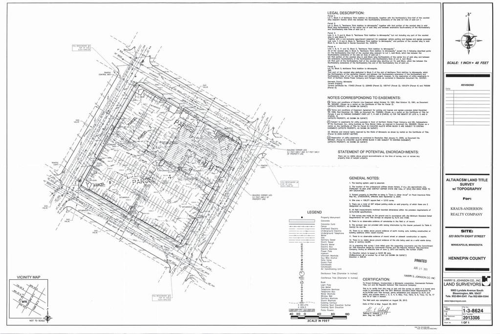
107
108 Know what's below. Call before you dig. KA BLOCK REDEVELOPMENT I hereby certify that this document was prepared by me or under my direct supervision and that I am a duly licensed Engineer under the laws of the State of Minnesota Signature Mike R. Kettler Typed or Printed Name License # Date Sunde Engineering, PLLC. CONSULTING CIVIL ENGINEERS 1030 NESTT ENE STH LMNTN, MNNEST TELEPHNE ORIGINAL ISSUE: REVISIONS PROJECT NUMBER MK DRAWN BY CHECKED BY KEY PLAN DEMOLITION PLAN C1.1 NOT FOR CONSTRUCTION LAND USE APPLICATION 1/29/ KA BLOCK REDEVELOPMENT
109 Know what's below. Call before you dig. KA BLOCK REDEVELOPMENT I hereby certify that this document was prepared by me or under my direct supervision and that I am a duly licensed Engineer under the laws of the State of Minnesota Signature Mike R. Kettler Typed or Printed Name License # Date Sunde Engineering, PLLC. CONSULTING CIVIL ENGINEERS 1030 NESTT ENE STH LMNTN, MNNEST TELEPHNE ORIGINAL ISSUE: REVISIONS PROJECT NUMBER MK DRAWN BY CHECKED BY KEY PLAN GRADING AND DRAINAGE PLAN C1.2 NOT FOR CONSTRUCTION LAND USE APPLICATION 1/29/ KA BLOCK REDEVELOPMENT
110 Know what's below. Call before you dig. KA BLOCK REDEVELOPMENT I hereby certify that this document was prepared by me or under my direct supervision and that I am a duly licensed Engineer under the laws of the State of Minnesota Signature Mike R. Kettler Typed or Printed Name License # Date Sunde Engineering, PLLC. CONSULTING CIVIL ENGINEERS 1030 NESTT ENE STH LMNTN, MNNEST TELEPHNE ORIGINAL ISSUE: REVISIONS PROJECT NUMBER MK DRAWN BY CHECKED BY KEY PLAN UTILITY PLAN C1.3 NOT FOR CONSTRUCTION LAND USE APPLICATION 1/29/ KA BLOCK REDEVELOPMENT
111 EL 1 CENTE LTE SSEML DELECT PLTE EL 2 TP C 10" LTE SSEML C C 30 H HL C M 101 KA BLOCK REDEVELOPMENT I hereby certify that this document was prepared by me or under my direct supervision and that I am a duly licensed Engineer under the laws of the State of Minnesota Signature Mike R. Kettler Typed or Printed Name /1/15 License # Date Sunde Engineering, PLLC. CONSULTING CIVIL ENGINEERS 1030 NESTT ENE STH LMNTN, MNNEST TELEPHNE ORIGINAL ISSUE: REVISIONS PROJECT NUMBER MK DRAWN BY CHECKED BY KEY PLAN NOTES AND DETAILS C1.4 : NOT FOR CONSTRUCTION LAND USE APPLICATION 1/29/ KA BLOCK REDEVELOPMENT
112 KA BLOCK REDEVELOPMENT I hereby certify that this document was prepared by me or under my direct supervision and that I am a duly licensed Engineer under the laws of the State of Minnesota Signature Mike R. Kettler Typed or Printed Name License # Date Sunde Engineering, PLLC. CONSULTING CIVIL ENGINEERS 1030 NESTT ENE STH LMNTN, MNNEST TELEPHNE NOT FOR CONSTRUCTION LAND USE APPLICATION 1/29/16 ORIGINAL ISSUE: REVISIONS No. Description Date PROJECT NUMBER MK DRAWN BY CHECKED BY KEY PLAN KA BLOCK REDEVELOPMENT EROSION CONTROL AND STORMWATER POLLUTION PREVENTION PLAN C1.5


113 KA BLOCK REDEVELOPMENT I hereby certify that this document was prepared by me or under my direct supervision and that I am a duly licensed Engineer under the laws of the State of Minnesota Signature Mike R. Kettler Typed or Printed Name License # Date Sunde Engineering, PLLC. CONSULTING CIVIL ENGINEERS 1030 NESTT ENE STH LMNTN, MNNEST TELEPHNE NOT FOR CONSTRUCTION LAND USE APPLICATION 1/29/16 ORIGINAL ISSUE: REVISIONS No. Description Date PROJECT NUMBER MK DRAWN BY CHECKED BY KEY PLAN KA BLOCK REDEVELOPMENT STORMWATER SYSTEM DETAILS C1.6
114 KA BLOCK 810 Portland Avenue South Minneapolis, MN I hereby certify that this document was prepared by me or under my direct supervision and that I am a duly licensed Engineer under the laws of the State of Minnesota Signature Mike R. Kettler Typed or Printed Name License # Date Sunde Engineering, PLLC. CONSULTING CIVIL ENGINEERS 1030 NESTT ENE STH LMNTN, MNNEST TELEPHNE NOT FOR CONSTRUCTION LAND USE APPLICATION 1/29/16 ORIGINAL ISSUE: REVISIONS PROJECT NUMBER MK DRAWN BY CHECKED BY KEY PLAN KA BLOCK REDEVELOPMENT SITE PLAN C1.7
115 TH STEET AREA OF STRUCTURAL AREA OF STRUCTURAL AREA OF STRUCTURAL SOIL (1,000 CU FT) SOIL (1,000 CU FT) SOIL (1,000 CU FT) (7) KARL FOERSTER GRASS (7) KARL FOERSTER GRASS (7) KARL FOERSTER GRASS (2) LINDEN (2) HACKBERRY (2) LINDEN (45) HOSTA (22) HOSTA (22) HOSTA (22) HOSTA (2) OAK (2) SERVICEBERRY AREA OF STRUCTURAL (4) DOGWOOD SOIL (2,500 CU FT) (4) ARBORVITAE (5) KARL FOERSTER GRASS (4) DOGWOOD (18) ASTER AREA OF STRUCTURAL SOIL (1,500 CU FT) (3) OAK (18) KARL FOERSTER GRASS S NDESN (3) REDBUD (19) DIANTHUS ANNUALS, TYP. (4) DOGWOOD (6) ARBORVITAE (4) DOGWOOD (2) OAK (6) ARBORVITAE (4) DOGWOOD ANNUALS, TYP. (9) CATMINT (1) SERVICEBERRY (7) KARL FOERSTER GRASS (4) ARBORVITAE TH ENE PTLND ENE (4) DOGWOOD (22) DIANTHUS (9) CATMINT (4) DOGWOOD (2) SERVICEBERRY (6) YEW PAVERS (4) DOGWOOD RELOCATED (9) SEDUM LIGHT ESDENT L (2) MAPLE SEE 2 / L1.3 FOR TREE GRATE DETAIL AREA OF STRUCTURAL SOIL (500 CU FT) AREA OF STRUCTURAL SOIL (1,500 CU FT) (3) MAPLE E E COLORED CONCRETE (9) SEDUM (4) HONEYLOCUST (64) ASTER (6) YEW (2) MAPLE (18) CATMINT SEE 1 / L1.3 ANNUALS, TYP. FOR TREE PLANTING DETAIL AT STRUCTURAL SOILS PAVER TREE GRATES, TYP. (4) ARBORVITAE (10) DOGWOOD AREA OF STRUCTURAL SOIL (2,000 CU FT) (4) ARBORVITAE (2) OAK (18) CATMINT ANNUALS, TYP. (22) DIANTHUS AREA OF STRUCTURAL SOIL (1,000 CU FT) (2) OAK HTEL ANNUALS, TYP. (1) REDBUD SEE 4 / L1.2 (4) ARBORVITAE FOR PERENNIAL ANNUALS, TYP. PLANTING DETAIL (7) KARL FOERSTER (18) ASTER GRASS ANNUALS, TYP. (6) ARBORVITAE AREA OF STRUCTURAL SOIL (1,000 CU FT) SEE 3 / L1.3 (2) REDBUD (3) PINE (3) PINE (3) PINE (3) PINE (3) PINE (3) PINE FOR SHRUB PLANTING (17) KARL FOERSTER GRASS DETAIL (7) SPIREA (7) SPIREA (7) SPIREA (7) SPIREA (7) SPIREA (7) SPIREA (20) SEDUM AREA OF STRUCTURAL SOIL (1,000 CU FT) (22) CATMINT (3) PINE (22) CATMINT (22) CATMINT (2) LINDEN (3) PINE AREA OF STRUCTURAL SOIL (1,000 CU FT) (2) LINDEN (2) HACKBERRY (7) KARL FOERSTER GRASS (7) SPIREA (22) CATMINT (7) KARL FOERSTER GRASS (7) KARL FOERSTER GRASS AREA OF STRUCTURAL SOIL (1,000 CU FT) (2) HACKBERRY TH STEET (7) KARL FOERSTER GRASS 1 L1.0 LANDSCAPE PLAN - SITE SCALE 1" = 20'-0" PLNTN NTES 1. LCTE LL TLTES. 12. NSTLL 3" DEEP SHEDDED HD D MLCH NS T CN ES DECDS TEES TH N MLCH N D ECT CNTCT TH TEE TN. 2. STE PPSED PLNTN LCT NS PE PLN EE ND PPL LNDSCPE CHTECT P T NSTLL. 13. NSTLL 2" DEEP SHEDDED HD D MLCH NS T SH PLNTN ES TH N MLCH N D ECT CNTCT TH SH STEMS. 3. PLNT MTE L SHLL CMPL TH THE CENT EDT N THE MECN STNDD NSE STC, NS0.1. NLESS NTED THE SE, DECDS 1. NSTLL 2" DEEP NEL SHEDDED MLCH 1" DEEP SHEDDED HD D MLCH N PEENN L PLNTN EDS. EME LL MLCH M STEMS PEENN LS SHS SHLL HE T LEST CNES T THE SPEC ED HE HT. NMENTL TEES SHLL HE N '' CTCHES ND SHLL EN NCHN N L E THN 3' PLNT STEMS SHLD NT E N D ECT CNTCT TH MLCH. EET E THE T LL. STEET ND LED TEES SHLL EN NCHN N L E THN ' E PED SCE. 1. NT NE PLNT MTE L THH NE CLEND E M THE DTE SSTNT L CMPLET N. N PT L CCEPTNCE LL E CNSDEED.. NSTLL PLNT MTE L NCE NL DN ND CNSTCT N HS EEN CMPLETED N THE MMED TE E. 1. SPN PLNT MTE L NSTLLT N S M THE PL 1 T JNE 1.. NSTLL PLNT MTE LS PE PLNTN DETLS.. SSTTT N EESTS PLNT MTE L TPE S E SHLL E SMTTED T THE LNDSCPE CHTECT CNSDET N P T DDN. LL SSTTT NS TE DDN MST E PPED LNDSCPE CHTECT ND E SJECT T CNTCT DJSTMENTS.. DJSTMENTS N LCT N PPSED PLNT MTE LS M E NEEDED N ELD. LNDSCPE CHTECT MST E NT ED P T DJSTMENT PLNTS.. ETL E PLNT MTE L PN NSTLLT N TH DED NE MEL, THE PPED ETL E M ED N TH THE PLNTN SL PE THE MNCTE'S NSTCT NS M E TETED SMME ND LL NSTLLT N TH N PPLCT N NL PE 2." CLPE TEE ND. PE SH TH N DDT NL PPLCT N THE LL N SPN N THE TEE SCE.. NSTLL 1" DEPTH PLNTN SL N ES ECE N ND CE, PEENN LS, NNLS. PLNTN SL SHLL CNSST MnD T 3C MD ED T CNTN MMM 30 SND, PH.1 M, S THESE SPEC ED N THE PJECT MNL. 10. TEE PPN MTE L SHLL E T LLED PLSTC SHEETN PPLED M TN LE T ST NCH. P SMTHED DECDS TEES PLNTED N THE LL P T DECEME 1 ND EME PPN TE M " THC STEEL EDE T E SED T CNTN SHS, PEENN LS ND NNLS HEE PLNTN ED MEETS SD NLESS THE SE NTED. PPL PEEMEENT HECDE PEEN PPED ELN NNL, PEENN L, ND SH EDS LLED SHEDDED HDD MLCH. EE T SPEC CT NS DDT NL NMT N EDN SE HECDES. 1. LL CN ES PLNTN S CCEPTLE M ST 21 T SEPTEME LL DECDS PLNTN S CCEPTLE M ST 1 NTL NEME DJSTMENTS T PLNTN DTES MST E PPED N TN THE LNDSCPE CHTECT. T N NTES 1. CNTCT SHLL E ESPNS LE PDN N T N LT PLN ND SPEC CT N S PT THE SCPE. SMT LT PLN ND SPEC CT NS PPL THE LNDSCPE CHTECT P T DE ND CNSTCT N. T SHLL E THE CNTCT'S ESPNS LT T ENSE THT SDDEDSEEDED ND PLNTED ES E TED PPEL, NCLDN THSE ES D ECTL ND ND TTN LDN NDT N. 2. CNTCT SHLL E ESTN T N SSTEM LT ND CN M CMPLETE LMTS T N P T SPPLN SHP D NS. 3. CNTCT SHLL CNTCT LNDSCPE CHTECT NSPECT N ND PPL LL ES ECE N DP T N P T NSTLLT N N MLCH.. CNTCT SHLL PDE THE NE TH N T N SCHEDLE PPP TE T THE PJECT STE CNDT NS ND T PLNTED MTE L TH E EMENTS.. CNTCT SHLL ENSE THT SL CNDT NS ND CMPCT N E DETE T LL PPE DNE ND THE CNSTCT N STE. NDES LE CNDT NS SHLL E HT T THE TTENT N THE LNDSCPE CHTECT P T ENNN. T SHLL E THE LNDSCPE CNTCT'S ESPNS LT T ENSE PPE SCE ND SSCE DNE N PLNTN ES. 0 NTH LEEND AREA OF STRUCTURAL SOILS CU FT (8'X25'X2.5'); REFER TO 1 / L1.2 CONCRETE PAVERS REFER TO L1.1 DECIDUOUS OVERSTORY TREE EVERGREEN TREE DECIDUOUS ORNAMENTAL TREE DECIDUOUS SHRUB EVERGREEN SHRUB PERENNIAL / IVY ROOT KEY QTY BOTANICAL NAME COMMON NAME SIZE CONT. 25 DECDS SHDE TEES 7 ACER RUBRUM 'AUTUMN RADIANCE' MAPLE, AUTUMN RADIANCE B&B 2.5" CAL. 6 CELTIS OCCIENTALIS HACKBERRY B&B 2.5" CAL. 11 QUERCUS BICOLOR OAK, SWAMP WHITE B&B 2.5" CAL. 8 TILIA AMERICANA 'SENTRY' LINDEN, SENTRY B&B 2.5" CAL. 285 PEENN LS 68 CALAMAGROSTIS X ACUTIFLORA 'KARL FOERSTER' FEATHER REED GRASS, KARL FOERSTER CONT. #1 63 DIANTHUS 'FROSTY FIRE' DIANTHUS, FROST FIRE CONT. #1 66 HOSTA 'LANCIFOLIA' HOSTA, LANCIFOLIA CONT. #1 88 NEPETA FAASSENII 'KIT KAT' CATMINT, KIT KAT CONT. #1 PLNTN SCHEDLE HT L1.0 KA BLOCK REDEVELOPMENT elness swenson graham architects 500 washington avenue south minneapolis minnesota p f w w w. e s g a r c h. c o m I hereby certify that this document was prepared by me or under my direct supervision and that I am a duly licensed landscape architect under the laws of the State of Minnesota Signature Typed or Printed Name License # Date 401 2nd Avenue North, Suite 410 Minneapolis, MN p ORIGINAL ISSUE: REVISIONS PROJECT NUMBER MJR JS DRAWN BY CHECKED BY KEY PLAN L1.0 LANDSCAPE PLAN 0 NOT FOR CONSTRUCTION ROOT KEY QTY BOTANICAL NAME COMMON NAME SIZE CONT. 4 DECDS SHDE TEES 4 GLEDITSIA TRIACANTHOS VAR INERMIS 'SKYLINE' HONEYLOCUST, SKYLINE B&B 2.5" CAL. 11 NMENTL TEES 5 AMELANCHIER X GRANDIFLORA 'AUTUMN BRILLIANCE' SERVICEBERRY, AUTUMN BRILLIANCE B&B 8' HGT. MULTI-STEM 6 CERCIS CANADENSIS REDBUD, NORTHERN CLUMP B&B 8' HGT. MULTI-STEM 91 DECDS SHS 42 CORNUS SERICEA 'ISANTI' DOGWOOD, ISANTI CONT. #5 49 SPIREA X BUMALDA 'ANTHONY WATERER' SPIREA, ANTHONY WATERER CONT. #5 74 EEEEN SHS 24 PINUS STROBUS 'BLUE SHAG' PINE, BLUE SHAG CONT. #5 12 TAXUS X MEDIA 'TAUNTON' YEW, TAUNTON CONT. #5 38 THUJA OCCIDENTALIS 'BOBAZAM' ARBORVITAE, MR. BOWLING BALL CONT. #5 152 PEENN LS 100 ASTER NOVAE-ANGLIAE 'PURPLE DOME' ASTER, PURPLE DOME CONT. #1 15 CALAMAGROSTIS X ACUTIFLORA 'KARL FOERSTER' FEATHER REED GRASS, KARL FOERSTER CONT. #1 45 HOSTA 'LANCIFOLIA' HOSTA, LANCIFOLIA CONT. #1 54 NEPETA FAASSENII 'KIT KAT' CATMINT, KIT KAT CONT. #1 38 SEDUM X 'AUTUMN FIRE' SEDUM, AUTUMN FIRE CONT. #1 PLNTN SCHEDLE THN PPETL1.0 LAND USE APPLICATION 1/29/2016 No. Description Date KA BLOCK REDEVELOPMENT
 BIKE RACKS; REFER TO 5 / L1.")
 BIKE RACKS; REFER TO 5 / L1.3 (2) PLANTER 'C' (1) PLANTER 'D' (1) PLANTER 'C' (1) PLANTER 'C' (4) PLANTER 'A' (1) PLANTER 'D' (2) PLANTER 'D' LIGHT BOLLARD, TYP.")

116 PTLND ENE TH STEET SECE E E L NT DES TH STEET D N T PN SECE LNE C EE CTD ESDENCE DP HTEL DP TSH TSH ECCLN ME N TH ENE TNSMES S NDESN AREA WELL NE E E ESDENT L L alet PAVERS PAVERS RELOCATED LIGHT AREA SPECIAL PAVING REFER TO 1/L1.2 SEE 2 / L1.2 FOR TREE GRATE DETAIL COLORED CONCRETE, TYP. PAVER TREE GRATES, TYP. PAVERS COLORED CONCRETE REFER TO 1/L1.2 (3) BIKE RACKS; REFER TO 5 / L1.3 LIGHT BOLLARD, TYP. (4) PLANTER 'B' LIGHT COLUMN, TYP. HTEL AREA WELL AREA WELL (8) BIKE RACKS; REFER TO 5 / L1.3 ILLUMINATED BOLLARD, TYP. (8) BIKE RACKS; REFER TO 5 / L1.3 (2) PLANTER 'C' (1) PLANTER 'D' (1) PLANTER 'C' (1) PLANTER 'C' (4) PLANTER 'A' (1) PLANTER 'D' (2) PLANTER 'D' LIGHT BOLLARD, TYP. (4) PLANTER 'C' COLORED CONCRETE REFER TO 1/L1.2 AREA WELL PAVERS, TYP. PLANTING BED, TYP.; REFER TO 1 / L1.0 COLORED CONCRETE REFER TO 1/L1.2 PAVERS LEEND PERVIOUS LANDSCAPE AREAS COLORED CONCRETE PAVING AREA; REFER TO L1.2 PAVING PLAN FOR COLORS AND FINISHES. UNIT PAVERS PROPERTY LINE NCHS T CNC. " S TE CMPCTED CLSS " DEEP 2' SCNCETE SE CMPCTED SDE ELECTCL 1' " " " 2' 3'" " " ' 1' " PLN 3 " ENT STEEL P LN ED STEEL L HT LLD L.E.D. HTE L HT STP CCESS PNEL KA BLOCK REDEVELOPMENT elness swenson graham architects 500 washington avenue south minneapolis minnesota p f w w w. e s g a r c h. c o m I hereby certify that this document was prepared by me or under my direct supervision and that I am a duly licensed landscape architect under the laws of the State of Minnesota Signature Typed or Printed Name License # Date 401 2nd Avenue North, Suite 410 Minneapolis, MN p NOT FOR CONSTRUCTION 1 L1.1 LIGHTING & PUBLIC REALM PLAN SCALE 1" = 16'-0" 1 32 NTH 2 L1.1 LIGHT BOLLARD LIGHT COLUMN PLANTER 'A' - STEEL, PAINTED SILVER, 6'Wx6'Lx3'H PLANTER 'B' - STEEL, PAINTED SILVER, 3'Wx3'Lx2'H PLANTER 'C' - STEEL, PAINTED SILVER, 2.5'Wx6'Lx2'H PLANTER 'D' - STEEL, PAINTED SILVER, 2.5'Wx4'Lx2'H LIGHT BOLLARD LIGHT BOLLARD LIGHT COLUMN (EXELIA COLUMN BY SELUX,14' HEIGHT, TYPE 5 ALUMINUM REFLECTOR, SILVER FINISH) SECTION AT LIGHT BOLLARD SCALE 3/4" = 1'-0" LAND USE APPLICATION 1/29/2016 ORIGINAL ISSUE: REVISIONS No. Description Date PROJECT NUMBER MJR JS DRAWN BY CHECKED BY KEY PLAN KA BLOCK REDEVELOPMENT LIGHTING AND PUBLIC REALM PLAN L1.1 0


117 PTLND ENE 1 L1.2 PAVING PLAN SCALE 1" = 16'-0" S NDESN E E HTEL TH STEET TH STEET ESDENT L 1 32 NTH LEEND KA BLOCK REDEVELOPMENT elness swenson graham architects 500 washington avenue south minneapolis minnesota p f w w w. e s g a r c h. c o m I hereby certify that this document was prepared by me or under my direct supervision and that I am a duly licensed landscape architect under the laws of the State of Minnesota Signature Typed or Printed Name License # Date 401 2nd Avenue North, Suite 410 Minneapolis, MN p ORIGINAL ISSUE: REVISIONS PROJECT NUMBER MJR JS DRAWN BY CHECKED BY KEY PLAN L1.2 PAVING PLAN 0 NOT FOR CONSTRUCTION COLORED CONCRETE PAVING AREA: 26,774 SF (77% OF TOTAL SITE PAVING) REGULAR PAVING AREA: 7,956 SF (23% OF TOTAL SITE PAVING) ME COLOR A - 'BEIGE' - LIGHT SANDBLAST COLOR B - 'CHARCOAL' - LIGHT SANDBLAST COLOR B - 'CHARCOAL' - HEAVY SANDBLAST COLOR C - 'BROWN' - LIGHT SANDBLAST COLOR C - 'BROWN' - HEAVY SANDBLAST CONCRETE PAVERS PROPERTY LINE COLOR 'A' - BEIGE COLOR 'B' - CHARCOAL (LIGHT SANDBLAST) COLOR 'B' - CHARCOAL (HEAVY SANDBLAST) COLOR 'C' - BROWN TARGET STATION EXAMPLES OF COLORED CONCRETE WITH SANDBLAST FINISH LAND USE APPLICATION 1/29/2016 No. Description Date KA BLOCK REDEVELOPMENT
118 STRUCTURAL SOILS 8' MIN. STRUCTURAL SOILS NOTE: CONTRACTOR SHALL MAINTAIN TREES IN A PLUMB POSITION THROUGHOUT THE WARRANTY PERIOD. WRAP TREE TRUNKS ONLY UPON APPROVAL BY LANDSCAPE ARCHITECT. SEE SPECIFICATION # PROVIDE & INSTALL RODENT PROTECTION. 2" 1 HARDWIRE CLOTH MESH CYLINDER, 8" DIA. OR GREATER X 36" HGT.. STAKE IN PLACE. PER SPEC INSTALL TREE WITH ROOT FLARE VISIBLE AT TOP OF THE ROOT BALL. REMOVE SOIL IN LEVEL MANNER FROM TOP OF ROOT BALL TO EXPOSE 1ST 2" 1 OR LARGER MAIN ORDER ROOT IF NEEDED. SET ROOT BALL WITH MAIN ORDER ROOT 1" ABOVE ADJACENT GRADE. DO NOT COVER TOP OF ROOT BALL WITH SOIL. PLACE NO MULCH IN CONTACT WITH TREE TRUNK REMOVE BURLAP, TWINE, ROPE AND WIRE FROM TOP HALF OF ROOT BALL PLANTING SOIL, REFER TO SPECIFICATIONS, COMPACT TO 85% OF MAX. DRY UNIT WEIGHT ACCORDING TO ASTM D 698 SCARIFY SIDES OF TREE PIT WITH SPADE BY HAND TO BIND WITH PREPARED SOIL PLACE ROOT BALL ON UNDISTURBED OR COMPACTED SOIL TAMP SOIL AROUND ROOT BALL BASE FIRMLY WITH FOOT PRESSURE SO THAT ROOT BALL DOES NOT SHIFT UNDERGROUND DRAINTILE IF NEEDED PER PERCOLATION TEST RESULTS. TIE TO STORM DRAIN. 1 1 A 4" DIG PLANTING PIT 4" TO 6" DEEPER THAN ROOT BALL 1 L1.3 TREE PLANTING DETAIL SCALE 3/4" = 1'-0" BUILD 4" HIGH EARTH SAUCER BEYOND EDGE OF ROOT BALL EDGE CONDITION VARIES PAVING AND SUB-BASE C.U. CERTIFIED STRUCTURAL SOIL 2.5' DEPTH, SEE DRAWING FOR AREA AND SPEC. FOR INSTALLATION PROCEDURES 2-1/2' DEPTH STRUCTURAL SOILS PREPARE SOIL FOR THE ENTIRE BED 12" MIN. SEE PLAN NOTE: REFER TO EXTERIOR PLANTING SPECIFICATION INSTALL 2" LAYER OF MULCH, DO NOT PLACE IN CONTACT W/ SHRUB STEM APPLY PRE-EMERGENT HERBICIDE EDGE CONDITION VARIES EDGER, REFER TO PLAN AND SPECIFICATION LOOSEN ROOTS OF CONTAINER GROWN PLANTS EXCAVATE PLANT BED MIN. 4" DEEPER THAN ROOT BALL HGT. SCARIFY SIDES AND BOTTOM OF PLANTING BED WITH SPADE UNDISTURBED SUBGRADE 4" 3 L1.3 SHRUB PLANTING DETAIL SCALE 3/4" = 1'-0" 4 L1.3 NOTE: REFER TO EXTERIOR PLANTING SPECIFICATION PREPARE SOIL FOR THE ENTIRE BED INSTALL 1" LAYER OF SHREDDED HARDWOOD MULCH OR 2" LAYER OF FINELY SHREDDED HARDWOOD MULCH. DO NOT PLACE IN CONTACT WITH PLANT 6" REFER EDGE CONDITION VARIES MIN. TO PLAN EDGER, REFER TO PLAN AND SPECIFICAITON LOOSEN ROOTS OF CONTAINER GROWN PLANTS PLANTING SOIL SCARIFY SIDES AND BOTTOM OF PLANTING BED WITH SPADE UNDISTURBED SUBGRADE PERENNIAL PLANTING DETAIL SCALE 3/4" = 1'-0" KEYSTONE RIDGE DESIGNS INC., BOLLARD GV2E4, 2 LOOP PERMANENT BOLLARD, SET PLUMB, REFER TO PLAN 3'-0" FOR LOCATIONS REFER TO CONCRETE WALK DETAIL FOR PAVEMENT 1'-6" INFORMATION CONCRETE FOOTING, REINFORCE AS NECESSARY COMPACTED CLASS 5 AGGREGATE BASE COMPACTED OR UNDISTURBED SUBGRADE 18" MIN. 6" 4" 6" 3'-1" 42" 8'-0" NSMTH Paverrate tm 22 Trim ing PETE TEE TE S DES NED T SPPT PES E THE TEE ELL " x ". SME S LL ELDED M STEEL NLE TN T E NME 3 EPNDED STEEL STCTL TN TEE PENN T E 1" DE TES E T E DES NED HE PEDEST N TC NSHLN ED TEE N LMNM 12" M SLT PENNS CNCETE PLN PES LNDSCPE C SND JNTS 1" TEE PENN 0" 0" PE TE " " " S CNCETE TN TEE PT PLNTN SL CMPCTED SDE 5 L1.3 BIKE MOUNT BOLLARD (2 LOOP) SCALE 3/4"=1'-0" ' " " 2'" PLN 2 L1.3 SECTION TREE PAVER GRATE SCALE 3/4"=1'-0" KA BLOCK REDEVELOPMENT elness swenson graham architects 500 washington avenue south minneapolis minnesota p f w w w. e s g a r c h. c o m I hereby certify that this document was prepared by me or under my direct supervision and that I am a duly licensed landscape architect under the laws of the State of Minnesota Signature Typed or Printed Name License # Date 401 2nd Avenue North, Suite 410 Minneapolis, MN p NOT FOR CONSTRUCTION LAND USE APPLICATION 1/29/2016 ORIGINAL ISSUE: REVISIONS No. Description Date PROJECT NUMBER MJR JS DRAWN BY CHECKED BY KEY PLAN KA BLOCK REDEVELOPMENT LANDSCAPE DETAILS L1.3
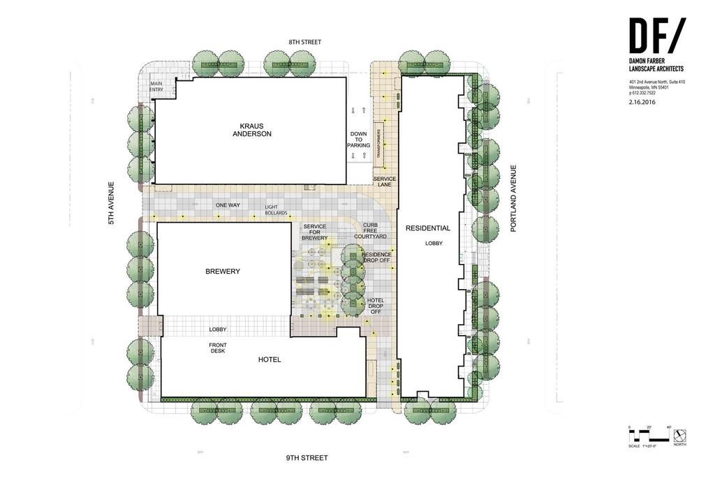
119


120 NOT FOR CONSTRUCTION VIEW FROM SOUTHEAST VIEW FROM SOUTHWEST


121 NOT FOR CONSTRUCTION VIEW NORTH FROM 5TH AVE S AND S 9TH ST SITE ON RIGHT SIDE OF IMAGE VIEW SOUTH FROM PORTLAND AVE AND S 8TH ST - SITE ON RIGHT SIDE OF IMAGE VIEW SOUTH FROM 5TH AVE S AND S 8TH ST - SITE ON LEFT SIDE OF IMAGE VIEW WEST FROM PORTLAND AVE AND S 9TH ST - SITE ON RIGHT SIDE OF IMAGE
122 EXHAUST AIR AREA WELL FOR PARKING BELOW HOTEL / BREWERY BIKE RACKS - 12 BIKES OUTLINE OF LEVELS ABOVE OFFICE BIKE RACKS - 6 BIKES OFFICE ONE WAY DRIVE BREWERY / EVENT CENTER / FINNOVATION OFFICE HOTEL / RESTAURANT EXHAUST AIR AREA WELL FOR PARKING BELOW RESIDENT BIKE RACKS - 16 BIKES TRANSFORMERS FOR RESIDENTIAL AND OFFICE BUILDINGS GENERATOR FOR BELOW GRADE PARKING LEVLES HOTEL / BREWERY BIKE RACKS - 16 BIKES 4'-0" TALL LOADING DOCK FRESH AIR FOR FOR BREWERY PARKING LEVELS BELOW 8'-0" TALL BREWERY GRAIN SILO GENERATOR FOR HOTEL AND BREWERY BUILDING METAL SCREEN WALL FENCE TRANSFORMERS FOR HOTEL AND BREWERY BUILDINGS CONC RETAINING WALL - 48" AFF RESIDENCE 1:20 ACCESSIBLE RAMP EXHAUST AIR AREA WELL FOR PARKING BELOW - AT PATIO LEVEL ONE WAY DRIVE GENERATOR FOR RESIDENCE NOT FOR CONSTRUCTION TRUE NORTH 1 ARCH SITE PLAN A.0.1 1/16" = 1'-0"

123 NOT FOR CONSTRUCTION AERIAL VIEW LOOKING NORTHWEST

124 NOT FOR CONSTRUCTION VIEW LOOKING NORTHWEST FROM PORTLAND AVENUE VIEW LOOKING NORTHEAST AT THE INTERSECTION OF 9TH STREET & 5TH AVENUE


125 NOT FOR CONSTRUCTION AERIAL VIEW LOOKING NORTHWEST AERIAL VIEW LOOKING EAST


126 NOT FOR CONSTRUCTION VIEW OF RESIDENTIAL BUILDING FROM MULTI-PURPOSE COURT VIEW OF PORTLAND AVENUE STREETSCAPE VIEW OF DOWNTOWN FROM RESIDENTIAL BUILDING AMENITY ROOF TERRACE DETAIL VIEW OF PORTLAND AVENUE STREETSCAPE


127 NOT FOR CONSTRUCTION VIEW OF HOTEL BUILDING FROM 9TH STREET LOOKING NORTHEAST VIEW OF HOTEL & BREWERY FROM 5TH AVENUE LOOKING SOUTHEAST 9TH ST. STREETSCAPE DETAIL VIEW OF HOTEL & BREWERY AND 5TH AVENUE STREETSCAPE DETAIL VIEW OF 9TH ST. STREETSCAPE VIEW OF HOTEL & BREWERY ENTRY AT 5TH AVENUE


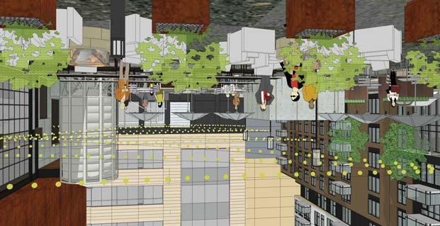
128 NOT FOR CONSTRUCTION NIGHTTIME VIEW OF MULTI-PURPOSE COURTYARD AND BREWERY BUILDING AERIAL VIEW OF MULTI-PURPOSE COURTYARD LOOKING NORTHWEST AERIAL VIEW OF MULTI-PURPOSE COURTYARD LOOKING SOUTHWEST GROUND LEVEL VIEW OF BREWERY & MULTI-PURPOSE COURTYARD LOOKING NORTHWEST GROUND LEVEL VIEW OF MULTI-PURPOSE COURTYARD FROM HOTEL


129 NOT FOR CONSTRUCTION VIEW OF OFFICE BUILDING LOOKING SOUTHWEST ALONG 5TH AVENUE VIEW OF OFFICE BUILDING LOOKING NORTHEAST AT 5TH AVENUE VIEW OF OFFICE BUILDING FROM 5TH AVENUE LOOKING SOUTHEAST VIEW OF OFFICE BUILDING LOOKING NORTHWEST ALONG 8TH STREET


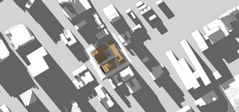
130 NOT FOR CONSTRUCTION JUNE 9AM JUNE NOON JUNE 3PM MARCH/ SEPTEMBER 9AM MARCH/ SEPTEMBER NOON MARCH/ SEPTEMBER 3PM DECEMBER 9AM DECEMBER NOON DECEMBER 3PM TRUE NORTH PORTLAND AVE PORTLAND AVE PORTLAND AVE S 8th ST S 8th ST S 8th ST FIFTH AVE S S 9th ST FIFTH AVE S S 9th ST FIFTH AVE S S 9th ST FIFTH AVE S S 8th ST S 8th ST FIFTH AVE S PORTLAND AVE S 9th ST PORTLAND AVE S 9th ST FIFTH AVE S S 8th ST S 8th ST FIFTH AVE S PORTLAND AVE S 9th ST PORTLAND AVE S 9th ST S 8th ST S 8th ST FIFTH AVE S FIFTH AVE S PORTLAND AVE PORTLAND AVE S 9th ST S 9th ST
131 321' - 5" 323' - 7" 11' - 5" 8' - 0" 8' - 0" 8' - 0" 8' - 0" 8' - 0" 8' - 0" 8' - 0" 322' - 9" 83' - 4 1/2" 121' - 6 1/2" 118' - 8" 8' - 0" 8' - 0" 23' - 0" 22' - 0" 22' - 0" 23' - 0" 8' - 0" 8' - 0" 8' - 0" 8' - 0" 8' - 0" 8' - 0" 8' - 0" 8' - 0" 8' - 0" 8' - 0" 8' - 0" 8' - 0" 8' - 0" 8' - 0" 8' - 0" 8' - 0" 8' - 0" 8' - 0" 8' - 0" 8' - 0" 8' - 0" 8' - 0" 8' - 0" 8' - 0" 8' - 0" 8' - 0" 8' - 0" 8' - 0" 22' - 0" 22' - 0" 22' - 0" 24' - 7" 22' - 0" 8' - 0" 22' - 0" 22' - 6" 23' - 0" 22' - 6" 23' - 0" 22' - 0" 22' - 0" 22' - 0" 23' - 0" 22' - 0" 18' - 0" EXHAUST AIR AREA WELL 23' - 5" 18' - 0" 18' - 0" 18' - 0" 18' - 0" 22' - 10" 22' - 3" 18' - 0" 18' - 0" 18' - 0" 8' - 0" 8' - 0" 8' - 0" 8' - 0" 8' - 0" 8' - 0" 17' - 2" 8' - 0" 8' - 0" 8' - 0" 8' - 0" 8' - 0" 8' - 0" 8' - 0" 8' - 0" 18' - 0" 15' - 0" 18' - 0" 18' - 0" 15' - 0" 25' - 6" 15' - 0" 18' - 0" 23' - 0" 24' - 10" 25' - 2" 24' - 0" 18' - 0" 25' - 6" 18' - 0" 18' - 0" 22' - 11" EXHAUST AIR AREA WELL 18' - 0" 15' - 0" EXHAUST AIR AREA WELL EXHAUST AIR AREA WELL BREWERY ELEVATORS HOTEL STAIR OFFICE ELEVATORS AND STAIR FRESH AIR INTAKE AREA WELL OFFICE STAIR 18' - 0" HOTEL STAIR RESIDENCE ELEVATORS AND STAIR 18' - 0" ELEVATOR SHAFT NOT FOR CONSTRUCTION 1 LEVEL P2 PLAN A.1.0a 1/16" = 1'-0"
132 EXHAUST AIR AREA WELL 321' - 5" 8' - 0" 8' - 0" 8' - 0" 8' - 0" 83' - 4 1/2" 8' - 0" 8' - 0" 8' - 0" 8' - 0" 121' - 6 1/2" 118' - 8" 323' - 7" 8' - 0" 8' - 0" 8' - 0" 8' - 0" 8' - 0" 8' - 0" 8' - 0" 8' - 0" 8' - 0" 8' - 0" 8' - 0" 8' - 0" 8' - 0" 322' - 9" 8' - 0" 8' - 0" 8' - 0" EXHAUST AIR AREA WELL 8' - 0" 8' - 0" 8' - 0" OFFICE WATER ROOM 22' - 0" 22' - 0" 8' - 0" 8' - 0" 8' - 0" OFFICE STAIR 8' - 0" OFFICE ELEVATORS AND STAIR ELECTRICAL ROOM 8' - 0" 8' - 0" 1' - 0 1/2" 4' - 0" 23' - 0" 8' - 0" 22' - 0" 8' - 0" 22' - 0" 8' - 0" Storage 8' - 0" 8' - 0" 22' - 6" 13' - 0" ONE WAY 13' - 0" ONE WAY 8' - 0" 23' - 0" 22' - 6" ONE WAY 19' - 6" 22' - 0" 22' - 6" BREWERY MECH 8' - 0" 8' - 0" 8' - 0" 8' - 0" 25' - 6" 8' - 0" 22' - 0" 22' - 0" 22' - 11" 22' - 6" 24' - 7" 21' - 11" 22' - 0" 22' - 0" 22' - 0" EXHAUST AIR AREA WELL EXHAUST AIR AREA WELL BREWERY ELEVATORS HOTEL STAIR RESIDENCE WATER ROOM 18' - 0" 8' - 0" 18' - 0" NOT FOR CONSTRUCTION 1 LEVEL P1 PLAN A.1.0b 1/16" = 1'-0" OFFICE BIKE RACKS - 4 BIKES RESIDENCEE LECTRICAL ROOM HOTEL STAIR ELEVATOR SHAFT HOTEL BIKE RACKS - 12 BIKES RESIDENCE MECHANICA ROOM RESIDENCE ELEVATORS AND STAIR 18' - 0" 18' - 0" 18' - 0" 18' - 0" 18' - 0" 18' - 0" PARKING WATER ROOM HOTEL / BREWERY WATER ROOM HOTEL ELECTRICAL ROOM 15' - 0" 18' - 0"


133 RESIDENT BIKE RACKS - 16 BIKES 108' - 11" EXHAUST AIR AREA WELL FOR PARKING BELOW HOTEL / BREWERY BIKE RACKS - 12 BIKES OUTLINE OF LEVELS ABOVE OFFICE BIKE RACKS - 6 BIKES 9' - 10" EXHAUST AIR AREA WELL FOR PARKING BELOW CONC RETAINING WALL - 48" AFF TRANSFORMERS FOR RESIDENTIAL AND OFFICE BUILDINGS GENERATOR FOR BELOW GRADE PARKING LEVLES HOTEL / BREWERY BIKE RACKS - 16 BIKES 4'-0" TALL LOADING DOCK FRESH AIR FOR FOR BREWERY PARKING LEVELS BELOW 8'-0" TALL BREWERY GRAIN SILO GENERATOR FOR HOTEL AND BREWERY BUILDING METAL SCREEN WALL FENCE TRANSFORMERS FOR HOTEL AND BREWERY BUILDINGS 1:20 ACCESSIBLE RAMP EXHAUST AIR AREA WELL FOR PARKING BELOW - AT PATIO LEVEL 2 20' - 6" 94' - 6" OFFICE ONE WAY DRIVE A.2.1b BREWERY / EVENT CENTER / FINNOVATION OFFICE HOTEL / RESTAURANT RESIDENCE 2 ONE WAY DRIVE A.2.2b A.2.1a A.2.2a A.2.2a A.2.1a A.2.2b GERATOR FOR RESIDENCE A.2.0c A.2.1c A.1.1 TRANSFORMER SCREEN WALL SEE 2/A1.1 A.1.1 A.2.0b A.2.0b A.2.0a PRE OXIDIZED STEEL SCREENING MATERIAL AT BOTH TRANFORMER ENCLOSURES NOT FOR CONSTRUCTION 1 STREET LEVEL PLAN A.1.1 1/16" = 1'-0" TRANSFORMER ENCLOSURE A /2" = 1'-0" 2 TRUE NORTH
134 7' - 3" 140' - 0" 207' - 2" 34' - 4" 64' - 4" 61' /2" 114' - 11" 37' - 3" 62' - 0" 3' - 8" 197' - 0" A.2.0a ' - 8" 17' - 6" 3' - 8" 324' - 7" A.2.2b A.2.1a OPEN TO BELOW A.2.2a OFFICE A.2.1b EVENT CENTER OPEN TO BELOW A.2.1a A.2.0b A.2.2b A.2.2a RESIDENCE OPEN TO BELOW OPEN TO BELOW A.2.0c A.2.1c 30' - 4" HOTEL 34' - 4" A.2.0b ' - 3" OUTDOOR TERRACE NOT FOR CONSTRUCTION 1 LEVEL 2 PLAN A.1.2 1/16" = 1'-0" TRUE NORTH
135 A.2.2a 19' - 11" 3' - 9" A.2.1b UP FINNOVATION OFFICE 62' - 0" 115' - 0" 37' - 3" 105' - 2" 37' - 3" 3' - 8" A.2.2b A.2.1a OUTDOOR TERRACE A.2.2b OFFICE A.2.2a 197' - 0" RESIDENCE 140' - 0" A.2.1c HOTEL A.2.1b 30' - 4" A.2.0c A.2.1c 34' - 4" 1' - 4 1/2" 216' - 0" 34' - 4" 64' - 4" A.2.1a A.2.0b A.2.0a NOT FOR CONSTRUCTION 1 LEVEL 3 PLAN A.1.3 1/16" = 1'-0" TRUE NORTH
136 248' - 1 1/4" 63' - 8" 3' - 9" A.2.0b OFFICE: LEVEL 4 197' - 0" 140' - 0" A.2.1b A.2.0c ROOF BELOW ROOF BELOW A.2.1c A.2.1b 30' - 4" HOTEL: LEVELS ' - 4" RESIDENCE: LEVELS ' - 0" 34' - 4" 64' - 4" A.2.1a A.2.0a ' - 0" 115' - 0" 37' - 3" 105' - 2" 3' - 8" A.2.2b A.2.1a A.2.2a A.2.2b A.2.2a A.2.1c NOT FOR CONSTRUCTION 20' - 6" 37' - 3" 1 LEVELS 4-8 PLAN A.1.4 1/16" = 1'-0" TRUE NORTH
137 A.2.2b A.2.1a A.2.2a A.2.0b A.2.2b A.2.2a A.2.1b A.2.0c A.2.1c A.2.1c A.2.1b HOTEL: LEVEL 8 RESIDENCE: LEVEL 9 30' - 6 1/2" A.2.1a A.2.0b A.2.0a ' - 7 3/4" 23' - 11" 222' - 5" 67' /4" 222' - 0" 32' - 6" 35' - 5 1/2" ROOF TERRACE OFFICE: LEVEL 5 23' - 10" 173' - 2" ROOF BELOW ROOF BELOW ROOF TERRACE RESTAURANT LEASE SPACE HOTEL ROOF TERRACE 216' - 9 1/2" 30' - 6 1/2" 4' - 0" 64' - 4" NOT FOR CONSTRUCTION TRUE NORTH 20' - 6" 94' - 6" 37' - 2" 108' - 11" 20' - 6" 37' - 2" 1 LEVEL 9 A.1.5 1/16" = 1'-0"
138 A.2.0a ' - 3 3/4" A.2.0c A.2.0b A.2.0b A.2.0c 67' /4" 67' - 4 1/2" A.2.0b A.2.0b A.2.0a NOT FOR CONSTRUCTION TRUE NORTH 237' - 3 3/4" 2 LEVELS A.1.6 1/16" = 1'-0" 1 LEVELS A.1.6 1/16" = 1'-0" TRUE NORTH

139 B14 B13 B12B11.8 B11 B10.5 B10 B9.1 B9 B8.1 B8 B7 B6 B5.9 B5 B4.4 B4 B3.3 B3.2 B3 B2.1 B1.4 B1.3 B1 METAL PANEL 5A PREFINISHED ALUMINUM RAILING WITH GLASS INLAY PANELS PREFINISHED ALUMINUM METAL PANEL 5B WINDOW SYSTEM AT METAL PANEL WALL METAL PANEL 5A METAL PANEL 5A METAL PANEL 5B ACM COLUMN COVER ALUMINUM CURTAINWALL SYSTEM ALUMINUM RAILING SYSTEM WITH GLASS INLAY PANELS MECHANICAL GRILLE CUSTOM COLOR TO MATCH METAL PANEL BRICK METAL PANEL 5C METAL PANEL 5D PREFINISHED SHEET FIBERGLASS WINDOW METAL ACCENT PANEL SYSTEM AT BRICK WINDOW HEADS OR AND MTL PANEL BAYS SILLS AS SHOWN METAL PANEL 5C PREFINISHED ALUMINUM RAILING WITH GLASS INLAY PANELS BRICK METAL PANEL 5C METAL PANEL 5D MECHANICAL GRILLE CUSTOM COLOR TO MATCH BRICK PAINTED GALVANIZED STEEL TRELLIS ENTRY CANOPY WITH WOOD SLAT INFILL. TYP ALL WALK-UP UNITS ARCHITECTURAL CONCRETE ENTRY TERRACES PREFIN ALUM RAILINGS AT ENTRY STAIRS AND TERRACE 1 RESIDENTIAL - EAST ELEVATION A.2.0a 3/32" = 1'-0" 9' - 8" 11' - 0" 11' - 0" WALL MOUNTED ACM ENTRY CANOPY LIGHT SCONCE, TYP AT ALL GROUND LEVEL UNIT ENTRIES, 6" DIAM, DARK BRONZE 9' - 8" 9' - 8" 9' - 8" 9' - 8" 9' - 8" 11' - 4" 11' - 4" 9' - 8" 9' - 8" 9' - 8" 9' - 8" 9' - 8" 9' - 8" 12' - 0" 182' - 8" 10' - 0" ALUMINUM RAILING SYSTEM WITH GLASS INLAY PANELS NOT FOR CONSTRUCTION

140 B14 B13 B12B11.8 B11 B10.5 B10 B9.1 B9 B8.1 B8 B7 B6 B5.9 B5 B4.4 B4 B3.3 B3.2 B3 B2.1 B1.4 B1.3 B1 METAL PANEL 5A PREFINISHED ALUMINUM RAILING WITH GLASS INLAY PANELS PREFINISHED ALUMINUM METAL PANEL 5B WINDOW SYSTEM AT METAL PANEL WALL METAL PANEL 5A METAL PANEL 5A METAL PANEL 5B ACM COLUMN COVER ALUMINUM CURTAINWALL SYSTEM ALUMINUM RAILING SYSTEM WITH GLASS INLAY PANELS MECHANICAL GRILLE CUSTOM COLOR TO MATCH METAL PANEL BRICK METAL PANEL 5C METAL PANEL 5D PREFINISHED SHEET FIBERGLASS WINDOW METAL ACCENT PANEL SYSTEM AT BRICK WINDOW HEADS OR AND MTL PANEL BAYS SILLS AS SHOWN METAL PANEL 5C PREFINISHED ALUMINUM RAILING WITH GLASS INLAY PANELS BRICK METAL PANEL 5C METAL PANEL 5D MECHANICAL GRILLE CUSTOM COLOR TO MATCH BRICK PAINTED GALVANIZED STEEL TRELLIS ENTRY CANOPY WITH WOOD SLAT INFILL. TYP ALL WALK-UP UNITS ARCHITECTURAL CONCRETE ENTRY TERRACES PREFIN ALUM RAILINGS AT ENTRY STAIRS AND TERRACE 9' - 8" 9' - 8" 9' - 8" 11' - 0" 11' - 0" WALL MOUNTED ACM ENTRY CANOPY LIGHT SCONCE, TYP AT ALL GROUND LEVEL UNIT ENTRIES, 6" DIAM, DARK BRONZE 9' - 8" 9' - 8" 9' - 8" 11' - 4" 11' - 4" 9' - 8" 9' - 8" 9' - 8" 9' - 8" 9' - 8" 9' - 8" 12' - 0" 182' - 8" 10' - 0" ALUMINUM RAILING SYSTEM WITH GLASS INLAY PANELS NOT FOR CONSTRUCTION 1 RESIDENTIAL - EAST ELEVATION A.2.0a.1 3/32" = 1'-0"


141 12' - 0" 9' - 8" 9' - 8" 9' - 8" 9' - 8" 9' - 8" 9' - 8" 11' - 4" 11' - 4" 9' - 8" 9' - 8" 9' - 8" 9' - 8" 9' - 8" 9' - 8" 11' - 0" 11' - 0" 10' - 0" 182' - 8" BB BB.1 BC.1 BC.2 BC.8 BC.9 BD MECHANICAL GRILLE CUSTOM COLOR TO MATCH BRICK COLOR PAINTED GALVANIZED STEEL TRELLIS ENTRY CANOPY WITH WOOD SLAT INFILL. TYP ALL WALK-UP UNITS ARCHITECTURAL CONCRETE ENTRY TERRACE METAL PANEL 5A METAL PANEL 5B AT LEVEL 17 ALUMINUM RAILING SYSTEM WITH GLASS INLAY PANELS METAL PANEL 5A PREFINISHED SHEET METAL ACCENT WINDOW HEADS OR SILLS AS SHOWN MECHANICAL GRILLE CUSTOM COLOR TO MATCH METAL PANEL PREFINISHED ALUMINUM WINDOW SYSTEM AT METAL PANEL WALL METAL PANEL 5C BRICK FIBERGLASS WINDOW SYSTEM AT BRICK WALL MECHANICAL GRILLE CUSTOM COLOR TO MATCH BRICK COLOR BD BC.9 BC.8 BC.2 BC.1 BC BB.1 BB 12' - 0" 9' - 8" 9' - 8" 9' - 8" 9' - 8" 9' - 8" 9' - 8" 11' - 4" 11' - 4" 9' - 8" 9' - 8" 9' - 8" 9' - 8" 9' - 8" 9' - 8" 11' - 0" 11' - 0" 10' - 0" 182' - 8" WALL MOUNTED LIGHT SCONCE, 6" DIAM, DARK BRONZE NOT FOR CONSTRUCTION 2 RESIDENTIAL - SOUTH ELEVATION A.2.0b 3/32" = 1'-0" 1 RESIDENTIAL - NORTH ELEVATION A.2.0b 3/32" = 1'-0"
142 METAL PANEL 5A METAL PANEL 5B METAL PANEL 5A MECHANICAL GRILLE CUSTOM COLOR TO MATCH METAL PANEL COLOR PREFINISHED ALUMINUM WINDOW SYSTEM AT METAL PANEL WALL ACM COLUMN COVER METAL PANEL 5C FIBERGLASS WINDOW SYSTEM AT BRICK WALL AND MTL PANEL BAYS METAL PANEL 5C BRICK ACM ENTRY CANOPY BEYOND BB BB.1 BC.1 BC.2 BC.8 BC.9 BD MECHANICAL GRILLE CUSTOM COLOR TO MATCH BRICK COLOR PAINTED GALVANIZED STEEL TRELLIS ENTRY CANOPY WITH WOOD SLAT INFILL. TYP ALL WALK-UP UNITS ARCHITECTURAL CONCRETE ENTRY TERRACE 12' - 0" 9' - 8" 9' - 8" 9' - 8" 9' - 8" 9' - 8" 9' - 8" 11' - 4" 11' - 4" 9' - 8" 9' - 8" 9' - 8" 9' - 8" 9' - 8" 9' - 8" 11' - 0" 11' - 0" 10' - 0" 182' - 8" 12' - 0" 9' - 8" 9' - 8" 9' - 8" 9' - 8" 9' - 8" 9' - 8" 11' - 4" 11' - 4" 9' - 8" 9' - 8" 9' - 8" 9' - 8" 9' - 8" 9' - 8" 11' - 0" 11' - 0" 10' - 0" 182' - 8" ALUMINUM RAILING SYSTEM WITH GLASS INLAY PANELS WALL MOUNTED LIGHT SCONCE 6" DIAM, DARK BRONZE METAL PANEL 5A METAL PANEL 5B AT LEVEL 17 ALUMINUM RAILING SYSTEM WITH GLASS INLAY PANELS METAL PANEL 5A PREFINISHED SHEET METAL ACCENT WINDOW HEADS OR SILLS AS SHOWN MECHANICAL GRILLE CUSTOM COLOR TO MATCH METAL PANEL COLOR PREFINISHED ALUMINUM WINDOW SYSTEM AT METAL PANEL WALL METAL PANEL 5C BRICK FIBERGLASS WINDOW SYSTEM AT BRICK WALL MECHANICAL GRILLE CUSTOM COLOR TO MATCH BRICK COLOR BD BC.9 BC.8 BC.2 BC.1 BC BB.1 BB NOT FOR CONSTRUCTION 1 RESIDENTIAL - SOUTH ELEVATION A.2.0b.1 3/32" = 1'-0" 2 RESIDENTIAL - NORTH ELEVATION A.2.0b.1 3/32" = 1'-0"

143 12' - 0" 9' - 8" 9' - 8" 9' - 8" 9' - 8" 9' - 8" 9' - 8" 11' - 4" 11' - 4" 9' - 8" 9' - 8" 9' - 8" 9' - 8" 9' - 8" 9' - 8" 11' - 0" 11' - 0" 10' - 0" 182' - 8" B1 B1.3 B1.4 B2.1 B3 B3.2 B3.3 B4 B4.4 B5 B5.9 B6 B7 B8 B8.1 B9 B9.1 B10 B10.5 B11 B11.8 B12 B13 B14 METAL PANEL 5A METAL PANEL 5C SPANDREL METAL PANEL 5B AT LEVEL 17 METAL PANEL 5B AT LEVEL 17 MECHANICAL GRILLE: CUSTOM COLOR TO MATCH METAL PANEL COLOR ALUMINUM RAILING SYSTEM WITH GLASS INLAY PANELS PREFIN ALUM WINDOW SYSTEM AT MTL PANEL WALL METAL PANEL 5A PREFINISHED SHEET METAL PANEL 5A METAL ACCENT WINDOW HEADS OR SILLS AS SHOWN ALUMINUM RAILING SYSTEM WITH GLASS INLAY PANELS BRICK FIBERGLASS WINDOW SYSTEM AT BRICK WALL METAL PANEL 5C MECHANICAL GRILLE: CUSTOM COLOR TO MATCH BRICK COLOR ALUMINUM CURTAINWALL SYSTEM MECHANICAL GRILLE CUSTOM COLOR TO MATCH BRICK COLOR BRICK WALL MOUNTED METAL PANEL 5C WALL MOUNTED LIGHT SCONCE, LIGHT SCONCE, TYP. 6" DIAM LED, 6" DIAM LED DARK DARK BRONZE BRONZE ACM ENTRY CANOPY NOT FOR CONSTRUCTION 1 RESIDENTIAL - WEST ELEVATION A.2.0c 3/32" = 1'-0"

144 12' - 0" 9' - 8" 9' - 8" 9' - 8" 9' - 8" 9' - 8" 9' - 8" 11' - 4" 11' - 4" 9' - 8" 9' - 8" 9' - 8" 9' - 8" 9' - 8" 9' - 8" 11' - 0" 11' - 0" 10' - 0" 182' - 8" B1 B1.3 B1.4 B2.1 B3 B3.2 B3.3 B4 B4.4 B5 B5.9 B6 B7 B8 B8.1 B9 B9.1 B10 B10.5 B11 B11.8 B12 B13 B14 METAL PANEL 5A METAL PANEL 5C SPANDREL METAL PANEL 5B AT LEVEL 17 METAL PANEL 5B AT LEVEL 17 MECHANICAL GRILLE: CUSTOM COLOR TO MATCH METAL PANEL COLOR ALUMINUM RAILING SYSTEM WITH GLASS INLAY PANELS PREFIN ALUM WINDOW SYSTEM AT MTL PANEL WALL METAL PANEL 5A PREFINISHED SHEET METAL PANEL 5A METAL ACCENT WINDOW HEADS OR SILLS AS SHOWN ALUMINUM RAILING SYSTEM WITH GLASS INLAY PANELS BRICK FIBERGLASS WINDOW SYSTEM AT BRICK WALL METAL PANEL 5C MECHANICAL GRILLE: CUSTOM COLOR TO MATCH BRICK COLOR ALUMINUM CURTAINWALL SYSTEM MECHANICAL GRILLE: CUSTOM COLOR TO MATCH METAL PANEL COLOR BRICK METAL PANEL 5C WALL MOUNTED WALL MOUNTED LIGHT SCONCE LIGHT SCONCE 6" DIAM LED ACM ENTRY CANOPY 6" DIAM LED DARK BRONZE DARK BRONZE NOT FOR CONSTRUCTION 1 RESIDENTIAL - WEST ELEVATION A.2.0c.1 3/32" = 1'-0"
145 ALUMINUM COMPOSITE METAL PANEL ALUMINUM COMPOSITE METAL PANEL CA CA.4 CB.1 CC CC.9 CD.5 CE.2 CE.8 CF.7 CG METAL PANEL 5E ALUMINUM WINDOW, TYP 10' - 0" 9' - 0" HIGH-PRESSURE BRICK LAMINATE PANEL ALUMINUM RAILING WITH GLASS INLAY PANELS 10' - 0" ALUMINUM WINDOW UNITS, TYP 10' - 0" 103' - 0" 10' - 0" 10' - 0" DECORATIVE MECHANICAL GRILLE BRICK 14' - 0" 10' - 0" HIGH-PRESSURE LAMINATE PANEL METAL CANOPY 10' - 0" ALUMINUM STOREFRONT SYSTEM 10' - 0" METAL PANEL EQUIPMENT ENCLOSURE C1 C2 C3 C4 C5 C6 C7 C8 METAL STAIR ELEVATOR OVERRUN BEYOND HIGH PRESSURE LAMINATE PANEL ALUMINUM STEEL FRAME COMPOSITE METAL STRUCTURE AND PANEL BUILDING SIGNAGE; FINAL BRANDING AND METAL PANEL 5E GRAPHICS TBD STAIR TOWER WITH ALUMINUM RAILING BRICK VENEER METAL PANEL 5F SYSTEM W/ GLASS BEYOND INLAY PANELS ALUMINUM WINDOW UNIT, TYP ALUMINUM STOREFRONT SYSTEM METAL PANEL 5G BUTT-GLAZED ALUMINUM WINDOW SYSTEM ALUMINUM RAILING SYSTEM WITH GLASS INLAY PANELS ARCHITECTURAL PRECAST INSULATED CONCRETE WALL PANEL BRICK METAL PANEL 5E DECORATIVE MECHANICAL GRILLE HIGH PRESSURE LAMINATE PANEL METAL CANOPY 70' - 0" 20' - 0" 20' - 0" 29' - 0" 1' - 0" 103' - 0" BACKLIT METAL PANEL 5J WITH CUT OUT PATTERN ALUMINUM STOREFRONT SYSTEM NOT FOR CONSTRUCTION 1 HOTEL - SOUTH ELEVATION A.2.1a 3/32" = 1'-0" 2 BREWTEL - WEST ELEVATION A.2.1a 3/32" = 1'-0"


146 ALUMINUM COMPOSITE METAL PANEL ALUMINUM COMPOSITE METAL PANEL CA CA.4 CB.1 CC CC.9 CD.5 CE.2 CE.8 CF.7 CG METAL PANEL 5E ALUMINUM WINDOW, TYP 10' - 0" 9' - 0" HIGH-PRESSURE BRICK LAMINATE PANEL ALUMINUM RAILING WITH GLASS INLAY PANELS 10' - 0" ALUMINUM WINDOW UNITS, TYP 10' - 0" 103' - 0" 10' - 0" 10' - 0" DECORATIVE MECHANICAL GRILLE BRICK 14' - 0" 10' - 0" HIGH-PRESSURE LAMINATE PANEL METAL CANOPY 10' - 0" ALUMINUM STOREFRONT SYSTEM 10' - 0" METAL PANEL EQUIPMENT ENCLOSURE C1 C2 C3 C4 C5 C6 C7 C8 METAL STAIR ELEVATOR OVERRUN BEYOND HIGH PRESSURE LAMINATE PANEL ALUMINUM STEEL FRAME COMPOSITE METAL STRUCTURE AND PANEL BUILDING SIGNAGE; FINAL BRANDING AND METAL PANEL 5E GRAPHICS TBD STAIR TOWER WITH ALUMINUM RAILING BRICK VENEER METAL PANEL 5F SYSTEM W/ GLASS BEYOND INLAY PANELS ALUMINUM WINDOW UNIT, TYP ALUMINUM STOREFRONT SYSTEM METAL PANEL 5G BUTT-GLAZED ALUMINUM WINDOW SYSTEM ALUMINUM RAILING SYSTEM WITH GLASS INLAY PANELS ARCHITECTURAL PRECAST INSULATED CONCRETE WALL PANEL BRICK METAL PANEL 5E DECORATIVE MECHANICAL GRILLE HIGH PRESSURE LAMINATE PANEL METAL CANOPY 70' - 0" 20' - 0" 20' - 0" 29' - 0" 1' - 0" 103' - 0" BACKLIT METAL PANEL 5J WITH CUT OUT PATTERN ALUMINUM STOREFRONT SYSTEM NOT FOR CONSTRUCTION 1 HOTEL - SOUTH ELEVATION A.2.1a.1 3/32" = 1'-0" 2 BREWTEL - WEST ELEVATION A.2.1a.1 3/32" = 1'-0"

147 20' - 0" 20' - 0" 29' - 0" 1' - 0" 70' - 0" CA.2 CA.3 CB CC.1 CD CE CA CA.4 CB.1 CC CC.9 CD.5 STANDING SEAM METAL ROOF STEEL STRUCTURE AND BUILDING SIGNAGE; FINAL BRANDING AND GRAPHICS TBD METAL PANEL 5F METAL PANEL 5G SECTION PROFILE OF BUILDING IN FRONT BACKLIT METAL PANEL 5J WITH CUT- OUT PATTERN CE CD.5 CD CC.9 CC.1 CB.1 CB CA.4 CA.3 CA.2 CA METAL PANEL 5G ALUMINUM WINDOW SYSTEM ARCHITECTURAL PRECAST INSULATED CONCRETE WALL PANEL LOADING DOCK STEEL FRAME STRUCTURE AND BUILDING SIGNAGE BEYOND METAL PANEL 5G ARCHITECTURAL PRECAST INSULATED CONCRETE WALL PANEL 20' - 0" 20' - 0" 29' - 0" 1' - 0" 70' - 0" STANDING SEAM METAL ROOF ALUMINUM WINDOW UNITS SHEET METAL ACCENT WINDOW HEADS METAL CANOPY NOT FOR CONSTRUCTION 1 BREWERY - SOUTH ELEVATION A.2.1b 3/32" = 1'-0" 2 BREWERY - NORTH ELEVATION A.2.1b 3/32" = 1'-0"

148 20' - 0" 20' - 0" 29' - 0" 1' - 0" 70' - 0" CA.2 CA.3 CB CC.1 CD CE CA CA.4 CB.1 CC CC.9 CD.5 STANDING SEAM METAL ROOF STEEL STRUCTURE AND BUILDING SIGNAGE; FINAL BRANDING AND GRAPHICS TBD METAL PANEL 5F METAL PANEL 5G SECTION PROFILE OF BUILDING IN FRONT BACKLIT METAL PANEL 5J WITH CUT- OUT PATTERN CE CD.5 CD CC.9 CC.1 CB.1 CB CA.4 CA.3 CA.2 CA METAL PANEL 5G ALUMINUM WINDOW SYSTEM ARCHITECTURAL PRECAST INSULATED CONCRETE WALL PANEL LOADING DOCK STEEL FRAME STRUCTURE AND BUILDING SIGNAGE BEYOND METAL PANEL 5G ARCHITECTURAL PRECAST INSULATED CONCRETE WALL PANEL 20' - 0" 20' - 0" 29' - 0" 1' - 0" 70' - 0" STANDING SEAM METAL ROOF ALUMINUM WINDOW UNITS SHEET METAL ACCENT WINDOW HEADS METAL CANOPY NOT FOR CONSTRUCTION 1 BREWERY - SOUTH ELEVATION A.2.1b.1 3/32" = 1'-0" 2 BREWERY - NORTH ELEVATION A.2.1b.1 3/32" = 1'-0"


149 10' - 0" 10' - 0" 14' - 0" 10' - 0" 10' - 0" 10' - 0" 10' - 0" 10' - 0" 10' - 0" 9' - 0" 103' - 0" CG ALUMINUM COMPOSITE METAL PANEL ALUMINUM WINDOW UNITS, TYP BRICK DECORATIVE MECHANICAL GRILLE METAL PANEL 5E ALUMINUM STOREFRONT SYSTEM ALUMINUM COMPOSITE METAL PANEL ALUMINUM WINDOW UNITS, TYP METAL PANEL BAY BEYOND DECORATIVE MECHANICAL GRILLES METAL CANOPY BEYOND BRICK BRICK INSET PANELS METAL PANEL EQUIPMENT ENCLOSURE CF.7 C8 C7 CE.8 METAL PANEL 5F C6 CE.2 C5 CD.5 C4 C3 METAL CANOPY CC.9 SIGNAGE TOWER BEYOND; FINAL BRANDING AND GRAPHICS TBD METAL PANEL 5F CC C2 METAL ELEVATOR OVERRUN ALUMINUM COMPOSITE METAL PANEL HIGH PRESSURE LAMINATE PANEL METAL PANEL 5E BRICK CB.1 CA.4 ALUMINUM RAILING SYSTEM WITH GLASS INLAY PANELS C1 ALUMINUM STOREFRONT SYSTEM BUTT-GLAZED ALUMINUM WINDOW SYSTEM METAL PANEL 5G METAL CANOPY ARCHITECTURAL PRECAST INSULATED CONCRETE WALL PANEL LOADING DOCK OVERHEAD SERVICE DOOR CA NOT FOR CONSTRUCTION SECTION PROFILE OF BUILDING IN FRONT 69' - 0" 10' - 0" 10' - 0" 14' - 0" 10' - 0" 10' - 0" 10' - 0" 10' - 0" 10' - 0" 10' - 0" 9' - 0" 103' - 0" 1 HOTEL - NORTH ELEVATION A.2.1c 3/32" = 1'-0" 2 BREWTEL EAST ELEVATION A.2.1c 3/32" = 1'-0"
150 CG CF.7 CE.8 CE.2 CD.5 CC.9 CC ALUMINUM COMPOSITE METAL PANEL CB.1 ALUMINUM RAILING SYSTEM WITH GLASS INLAY PANELS CA.4 CA 10' - 0" 14' - 0" 10' - 0" 10' - 0" 10' - 0" 10' - 0" 10' - 0" 10' - 0" 9' - 0" 103' - 0" ALUMINUM COMPOSITE METAL PANEL ALUMINUM WINDOW UNITS, TYP BRICK DECORATIVE MECHANICAL GRILLE METAL PANEL 5E ALUMINUM STOREFRONT SYSTEM METAL ELEVATOR OVERRUN HIGH PRESSURE LAMINATE PANEL METAL PANEL 5E BRICK 10' - 0" ALUMINUM COMPOSITE METAL PANEL ALUMINUM WINDOW UNITS, TYP METAL PANEL BAY BEYOND DECORATIVE MECHANICAL GRILLES METAL CANOPY BEYOND BRICK BRICK INSET PANELS METAL PANEL EQUIPMENT ENCLOSURE C8 C7 METAL PANEL 5F C6 C5 C4 METAL CANOPY C3 SIGNAGE TOWER BEYOND; FINAL BRANDING AND GRAPHICS TBD METAL PANEL 5F C2 SECTION PROFILE OF BUILDING IN FRONT C1 ALUMINUM STOREFRONT SYSTEM BUTT-GLAZED ALUMINUM WINDOW SYSTEM METAL PANEL 5G METAL CANOPY 69' - 0" 10' - 0" 10' - 0" 14' - 0" 10' - 0" 10' - 0" 10' - 0" 10' - 0" 10' - 0" 10' - 0" 9' - 0" 103' - 0" ARCHITECTURAL PRECAST INSULATED CONCRETE WALL PANEL LOADING DOCK OVERHEAD SERVICE DOOR NOT FOR CONSTRUCTION 1 HOTEL - NORTH ELEVATION A.2.1c.1 3/32" = 1'-0" 2 BREWTEL EAST ELEVATION A.2.1c.1 3/32" = 1'-0"

151 16' - 0" 14' - 0" 14' - 0" 14' - 0" 14' - 0" 12' - 6" 16' - 0" 14' - 0" 14' - 0" 14' - 0" 14' - 0" 12' - 6" 84' - 6" 84' - 6" METAL WALL PANEL SYSTEM ARCHITECTURAL PRECAST WALL PANELS CURTAINWALL SYSTEM WITH INSULATED GLASS SPANDREL GLASS PRECAST CONCRETE PANELS METAL FACED CANOPY/ TRELLIS METAL WALL PANEL SYSTEM PREFINISHED ALUM WINDOW SYSTEM GLASS GUARDRAIL ARCHITECTURAL PRECAST WALL PANELS ALUMINUM WINDOW SYSTEM PROJECTING CANOPY WITH PREFINISHED METAL FASCIA PREFINISHED ALUM STOREFRONT SYSTEM STONE CLADDING OVER PRECAST WALL PANEL PREFINISHED MECHANICAL LOUVER SCREEN OVER TUBE STEEL FRAME STRUCTURE SPANDREL GLASS AA.5 AB AC AD AE AF PREFINISHED MECHANICAL LOUVER SCREEN OVER TUBE STEEL FRAME STRUCTURE SPANDREL GLASS PRECAST CONCRETE PANELS METAL FACED CANOPY/ TRELLIS METAL WALL PANEL SYSTEM PREFINISHED ALUM WINDOW SYSTEM GLASS GUARDRAIL ARCHITECTURAL PRECAST WALL PANELS CURTAINWALL SYSTEM W/ INSULATED GLASS PROJECTING CANOPY WITH PREFINISHED METAL FASCIA PREFINISHED ALUM STOREFRONT SYSTEM STONE CLADDING OVER PRECAST WALL PANEL METAL WALL PANEL SYSTEM ARCHITECTURAL PRECAST WALL PANELS CURTAINWALL SYSTEM WITH INSULATED GLASS SPANDREL GLASS PRECAST CONCRETE PANELS NOT FOR CONSTRUCTION 1 KA Office North Elevation A.2.2a 3/32" = 1'-0" 2 KA Office South Elevation A.2.2a 3/32" = 1'-0"


152 16' - 0" 14' - 0" 14' - 0" 14' - 0" 14' - 0" 12' - 6" 16' - 0" 14' - 0" 14' - 0" 14' - 0" 14' - 0" 12' - 6" 84' - 6" 84' - 6" METAL WALL PANEL SYSTEM ARCHITECTURAL PRECAST WALL PANELS CURTAINWALL SYSTEM WITH INSULATED GLASS SPANDREL GLASS PRECAST CONCRETE PANELS METAL FACED CANOPY/ TRELLIS METAL WALL PANEL SYSTEM PREFINISHED ALUM WINDOW SYSTEM GLASS GUARDRAIL ARCHITECTURAL PRECAST WALL PANELS ALUMINUM WINDOW SYSTEM PROJECTING CANOPY WITH PREFINISHED METAL FASCIA PREFINISHED ALUM STOREFRONT SYSTEM STONE CLADDING OVER PRECAST WALL PANEL PREFINISHED MECHANICAL LOUVER SCREEN OVER TUBE STEEL FRAME STRUCTURE SPANDREL GLASS AA.5 AB AC AD AE AF PREFINISHED MECHANICAL LOUVER SCREEN OVER TUBE STEEL FRAME STRUCTURE SPANDREL GLASS PRECAST CONCRETE PANELS METAL FACED CANOPY/ TRELLIS METAL WALL PANEL SYSTEM PREFINISHED ALUM WINDOW SYSTEM GLASS GUARDRAIL ARCHITECTURAL PRECAST WALL PANELS CURTAINWALL SYSTEM W/ INSULATED GLASS PROJECTING CANOPY WITH PREFINISHED METAL FASCIA PREFINISHED ALUM STOREFRONT SYSTEM STONE CLADDING OVER PRECAST WALL PANEL METAL WALL PANEL SYSTEM ARCHITECTURAL PRECAST WALL PANELS CURTAINWALL SYSTEM WITH INSULATED GLASS SPANDREL GLASS PRECAST CONCRETE PANELS NOT FOR CONSTRUCTION 1 KA Office North Elevation A.2.2a.1 3/32" = 1'-0" 2 KA Office South Elevation A.2.2a.1 3/32" = 1'-0"

153 16' - 0" 14' - 0" 14' - 0" 14' - 3" 13' - 9" 12' - 6" 16' - 0" 14' - 0" 14' - 0" 14' - 0" 14' - 0" 12' - 6" 84' - 6" 84' - 6" A1.2 A1.8 A2 A2.3 A2.9A3 A3.4 A3.9 A4 METAL PANEL SYSTEM ON STAIR TOWER PENTHOUSE METAL FACED CANOPY/ TRELLIS METAL WALL PANEL SYSTEM PREFINISHED ALUM WINDOW SYSTEM GLASS GUARDRAIL ARCHITECTURAL PRECAST WALL PANELS SPANDREL GLASS PROJECTING CANOPY WITH PREFINISHED METAL FASCIA STONE CLADDING OVER PRECAST WALL PANEL A4 A3.9 A3.4 A2.9 A3 A2.3 A2 A1.8 PREFINISHED MECHANICAL LOUVER SCREEN OVER TUBE STEEL FRAME STRUCTURE METAL WALL PANEL SYSTEM ARCHITECTURAL PRECAST WALL PANELS SPANDREL GLASS PREFINISHED ALUMINUM WINDOW SYSTEM PRECAST CONCRETE PANELS WITH INSETS A1.2 PREFINISHED MECHANICAL LOUVER SCREEN OVER TUBE STEEL FRAME STRUCTURE ARCHITECTURAL PRECAST WALL PANELS CURTAINWALL SYSTEM WITH INSULATED GLASS PREFINISHED ALUMINUM STOREFRONT SYSTEM STONE BASE & COLUMN CLADDING NOT FOR CONSTRUCTION 1 KA Office West Elevation A.2.2b 3/32" = 1'-0" 2 KA Office East Elevation A.2.2b 3/32" = 1'-0"
154 16' - 0" 14' - 0" 14' - 0" 14' - 0" 14' - 0" 12' - 6" 84' - 6" METAL PANEL SYSTEM ON STAIR TOWER PENTHOUSE METAL FACED CANOPY/ TRELLIS METAL WALL PANEL SYSTEM PREFINISHED ALUM WINDOW SYSTEM GLASS GUARDRAIL ARCHITECTURAL PRECAST WALL PANELS SPANDREL GLASS PROJECTING CANOPY WITH PREFINISHED METAL FASCIA STONE CLADDING OVER PRECAST WALL PANEL PREFINISHED MECHANICAL LOUVER SCREEN OVER TUBE STEEL FRAME STRUCTURE METAL WALL PANEL SYSTEM ARCHITECTURAL PRECAST WALL PANELS SPANDREL GLASS PREFINISHED ALUMINUM WINDOW SYSTEM PRECAST CONCRETE PANELS WITH INSETS A1.2 A1.8 A2 A2.3 A2.9A3 A3.4 A3.9 A4 A4 A3.9 A3.4 A2.9 A3 A2.3 A2 A1.8 A1.2 PREFINISHED MECHANICAL LOUVER SCREEN OVER TUBE STEEL FRAME STRUCTURE ARCHITECTURAL PRECAST WALL PANELS CURTAINWALL SYSTEM WITH INSULATED GLASS PREFINISHED ALUMINUM STOREFRONT SYSTEM STONE BASE & COLUMN CLADDING 12' - 6" 13' - 9" 14' - 3" 14' - 0" 14' - 0" 16' - 0" 84' - 6" NOT FOR CONSTRUCTION 1 KA Office West Elevation A.2.2b.1 3/32" = 1'-0" 2 KA Office East Elevation A.2.2b.1 3/32" = 1'-0"
155 January 29, 2016 Council Member Lisa Goodman 350 S. 5 th Street, Room 307 Minneapolis, MN Re: Kraus-Anderson Headquarters Block Land Use Application Dear Council Member Goodman: On behalf of Kraus-Anderson, Incorporated and Engelsma Limited Partnership (together, KA ) we are writing to let you know we are submitting the Land Use Application and Preliminary Development Review for the redevelopment of the KA block, located at 523 South Eighth Street, Minneapolis, MN We thank you for your input and suggestions to improve the project. A. In General I. DESCRIPTION OF THE PROJECT The vision of the proposed KA redevelopment is to transform an entire city block, consisting of a surface parking lot and antiquated office building, into a vibrant, high-density mixed use destination in East Downtown. This area of East Downtown is currently characterized by several large surface parking lots and is in need of creative infill redevelopment. The proposed project can also serve as a catalyst for future improvements and investment along the Portland Avenue Corridor. The proposed redevelopment includes a mix of compatible uses within a composition of high quality individual buildings set within a full block master plan offering several public urban design amenities and benefits: 1. A new Kraus-Anderson corporate home office of approximately 100,000 square feet. KA has been located on this site for over 75 years and wishes to retain and expand its presence in Minneapolis for decades to come and help fulfill the Minneapolis 2025 Vision. 2. A new Type 1 residential midrise building of approximately 306 dwelling units featuring innovative design to attract a full range of millennials to baby boomers who want to be part of this new exciting part of Minneapolis and help fulfill the Minneapolis 2025 Vision.
156 3. A new 161-key boutique hotel that is part of the Finnegan s vision for a boutique hotel to support the overall Finnegan s integrated urban brewery / innovation concept. 4. A Finnegan s Brewery, Event Center and FINNovation office space. a. The FINNovation Lab has three exciting elements: i. A Collaborative Community for Social Entrepreneurs: The FINNovation Lab will be a community of companies with revenue generating, sustainable business models that create living wage jobs in the community and provide positive social impact. ii. iii. For Businesses That Do Well and Do Good: The FINNovation Lab will cater specifically to social entrepreneurs and innovators businesses that do well and do good. It will provide a tailored ecosystem of support services from the start up to scaling phase of their business. Designed To Enhance Collaboration And Cross Pollination Of Ideas: The Lab space will be purposely designed to enhance collaboration and cross pollination of ideas among the diverse individuals, businesses and organizations that become a part of the lab community. It will be a hub for those passionate about social innovation, creativity and collaboration. b. Finnegan House is a destination development, combining the rapidly growing trends of the craft beer movement, collaborative workspaces, social entrepreneurship and experiential overnight accommodations to create a positive impact on the community and greater society. Finnegans will be the first beer company in the world to donate 100 percent of its profits back to the community, and will launch its first ever brewery and experiential brewery lodging experience with 161 guest rooms at Finnegan House. This community building space will also include an outdoor courtyard and event space with planned programming and events designed to engage the neighborhood and the greater community. A restaurant and bar will be located inside Finnegan House, to provide food and beverage services to the entire facility, including catering and room service. B. Key Overall Design Features and Public Benefits 1. Public Realm and Streetscape: a. Complete rebuilding and enhancements to the surrounding urban sidewalks at Portland Avenue, 9th Street, 5th Avenue and 8th Street.
157 b. All four sidewalk areas will feature green boulevards with street trees, new regular and decorative sidewalk pavement, street lighting, landscaping, and outdoor seating areas. c. Additional setbacks to provide a wider, more pedestrian friendly environment. d. Multipurpose service/drop off courtyard: Within the site will be a multi-purpose hardscape courtyard that can be used by the surrounding new development for staging a variety of activities, gatherings and outdoor dining. 2. Parking Strategy: All parking will be provided below street level in a two-level parking facility with limited access located off of 8th Street South. There will be no surface parking lots. Parking for the hotel and Innovation Center will be provided through an offset, shared parking strategy. 3. Architectural Design: a. Architectural design approach: The overall architectural strategy features three distinctly different building aesthetics within a harmonious overall block massing approach. The visual intent is the creation of a full block redevelopment that has grown organically over time. Type 1, 100-year concrete and steel construction will be used throughout. b. Streetscape public realm shaped by high density/active architecture: The architecture on all sides of the block, shaping the streetscape public realm, will feature a variety of high quality, engaging facades, multiple entry points, and significant expanses of transparent window area to create an active and comfortable public pedestrian environment. 4. Stormwater Management: The stormwater management design will follow City of Minneapolis best practices. 5. Green And Sustainable Features: The design will offer a pedestrian and transitoriented community that allows residents to live, work and play without the dependence on daily automobile usage. The development team is committed to the sustainable design principles reflected in the City s Comprehensive Plan. Our sustainable design mission is to promote livable communities through the use of energy efficient systems, green building practice, reduced dependency on automobiles, creative density, high quality pedestrian and bicycle public realm and preservation of natural resources. This mixed use project will feature a series of green elements including green construction and demolition practices, green material specifications, thermal high-efficiency windows, and exterior envelope systems, and participation in the Xcel Energy Design Assistance Program.
158 January 29, 2016 Elliot Park Neighborhood, Inc. Attn: Kim Forbes, President th Street South, Suite170 Minneapolis, MN Re: Kraus-Anderson Headquarters Block Land Use Application Dear EPNI Board: On behalf of Kraus-Anderson, Incorporated and Engelsma Limited Partnership (together, KA ) we are writing to let you know we are submitting the Land Use Application and Preliminary Development Review for the redevelopment of the KA block, located at 523 South Eighth Street, Minneapolis, MN Thank you for the helpful feedback you have given to the project over the several meetings we have had with EPNI. A. In General I. DESCRIPTION OF THE PROJECT The vision of the proposed KA redevelopment is to transform an entire city block, consisting of a surface parking lot and antiquated office building, into a vibrant, high-density mixed use destination in East Downtown. This area of East Downtown is currently characterized by several large surface parking lots and is in need of creative infill redevelopment. The proposed project can also serve as a catalyst for future improvements and investment along the Portland Avenue Corridor. The proposed redevelopment includes a mix of compatible uses within a composition of high quality individual buildings set within a full block master plan offering several public urban design amenities and benefits: 1. A new Kraus-Anderson corporate home office of approximately 100,000 square feet. KA has been located on this site for over 75 years and wishes to retain and expand its presence in Minneapolis for decades to come and help fulfill the Minneapolis 2025 Vision. 2. A new Type 1 residential midrise building of approximately 306 dwelling units featuring innovative design to attract a full range of millennials to baby boomers who want to be part of this new exciting part of Minneapolis and help fulfill the Minneapolis 2025 Vision.
159 3. A new 161-key boutique hotel that is part of the Finnegan s vision for a boutique hotel to support the overall Finnegan s integrated urban brewery / innovation concept. 4. A Finnegan s Brewery, Event Center and FINNovation office space. a. The FINNovation Lab has three exciting elements: i. A Collaborative Community for Social Entrepreneurs: The FINNovation Lab will be a community of companies with revenue generating, sustainable business models that create living wage jobs in the community and provide positive social impact. ii. iii. For Businesses That Do Well and Do Good: The FINNovation Lab will cater specifically to social entrepreneurs and innovators businesses that do well and do good. It will provide a tailored ecosystem of support services from the start up to scaling phase of their business. Designed To Enhance Collaboration And Cross Pollination Of Ideas: The Lab space will be purposely designed to enhance collaboration and cross pollination of ideas among the diverse individuals, businesses and organizations that become a part of the lab community. It will be a hub for those passionate about social innovation, creativity and collaboration. b. Finnegan House is a destination development, combining the rapidly growing trends of the craft beer movement, collaborative workspaces, social entrepreneurship and experiential overnight accommodations to create a positive impact on the community and greater society. Finnegans will be the first beer company in the world to donate 100 percent of its profits back to the community, and will launch its first ever brewery and experiential brewery lodging experience with 161 guest rooms at Finnegan House. This community building space will also include an outdoor courtyard and event space with planned programming and events designed to engage the neighborhood and the greater community. A restaurant and bar will be located inside Finnegan House, to provide food and beverage services to the entire facility, including catering and room service. B. Key Overall Design Features and Public Benefits 1. Public Realm and Streetscape: a. Complete rebuilding and enhancements to the surrounding urban sidewalks at Portland Avenue, 9th Street, 5th Avenue and 8th Street.
160 b. All four sidewalk areas will feature green boulevards with street trees, new regular and decorative sidewalk pavement, street lighting, landscaping, and outdoor seating areas. c. Additional setbacks to provide a wider, more pedestrian friendly environment. d. Multipurpose service/drop off courtyard: Within the site will be a multi-purpose hardscape courtyard that can be used by the surrounding new development for staging a variety of activities, gatherings and outdoor dining. 2. Parking Strategy: All parking will be provided below street level in a two-level parking facility with limited access located off of 8th Street South. There will be no surface parking lots. Parking for the hotel and Innovation Center will be provided through an offset, shared parking strategy. 3. Architectural Design: a. Architectural design approach: The overall architectural strategy features three distinctly different building aesthetics within a harmonious overall block massing approach. The visual intent is the creation of a full block redevelopment that has grown organically over time. Type 1, 100-year concrete and steel construction will be used throughout. b. Streetscape public realm shaped by high density/active architecture: The architecture on all sides of the block, shaping the streetscape public realm, will feature a variety of high quality, engaging facades, multiple entry points, and significant expanses of transparent window area to create an active and comfortable public pedestrian environment. 4. Stormwater Management: The stormwater management design will follow City of Minneapolis best practices. 5. Green And Sustainable Features: The design will offer a pedestrian and transitoriented community that allows residents to live, work and play without the dependence on daily automobile usage. The development team is committed to the sustainable design principles reflected in the City s Comprehensive Plan. Our sustainable design mission is to promote livable communities through the use of energy efficient systems, green building practice, reduced dependency on automobiles, creative density, high quality pedestrian and bicycle public realm and preservation of natural resources. This mixed use project will feature a series of green elements including green construction and demolition practices, green material specifications, thermal high-efficiency windows, and exterior envelope systems, and participation in the Xcel Energy Design Assistance Program.
161 II. LAND USE APPLICATIONS To the best of our knowledge, the applications required for the project are: A. Planned Unit Development ( PUD ); B. Conditional use permit for height; C. Site plan review; D. Registered Land Survey; and E. Signage (as part of PUD application). III. ADDRESS OF PROPERTY 523 South Eighth Street, Minneapolis, MN IV. APPLICANT S CONTACT INFORMATION Burton L. Coffin Elness Swenson Graham Architects Inc. 500 Washington Ave S. #1080 Minneapolis, MN Thank you. We look forward to continuing to work with you on this exciting project. Sincerely, Elness Swenson Graham Architects, Inc. Burton L. Coffin, Associate AIA Vice President Cc: M. Korsh, D. Graham, K. Lamb

162 January 29, 2016 Downtown Minneapolis Neighborhood Association Attn: Nicholas Cichowicz, Chair 40 S. 7 th Street, Suite 212 PMB 172 Minneapolis, MN Re: Kraus-Anderson Headquarters Block Land Use Application Dear DMNA Board: On behalf of Kraus-Anderson, Incorporated and Engelsma Limited Partnership (together, KA ) we are writing to let you know we are submitting the Land Use Application and Preliminary Development Review for the redevelopment of the KA block, located at 523 South Eighth Street in the Elliot Park Neighborhood, adjacent to the Downtown Minneapolis Neighborhood Association. We are excited to be a part of the significant revitalization that is ongoing in this area. A. In General I. DESCRIPTION OF THE PROJECT The vision of the proposed KA redevelopment is to transform an entire city block, consisting of a surface parking lot and antiquated office building, into a vibrant, high-density mixed use destination in East Downtown. This area of East Downtown is currently characterized by several large surface parking lots and is in need of creative infill redevelopment. The proposed project can also serve as a catalyst for future improvements and investment along the Portland Avenue Corridor. The proposed redevelopment includes a mix of compatible uses within a composition of high quality individual buildings set within a full block master plan offering several public urban design amenities and benefits: 1. A new Kraus-Anderson corporate home office of approximately 100,000 square feet. KA has been located on this site for over 75 years and wishes to retain and expand its presence in Minneapolis for decades to come and help fulfill the Minneapolis 2025 Vision. 2. A new Type 1 residential midrise building of approximately 306 dwelling units featuring innovative design to attract a full range of millennials to baby boomers who want to be part of this new exciting part of Minneapolis and help fulfill the Minneapolis 2025 Vision.
163 3. A new 161-key boutique hotel that is part of the Finnegan s vision for a boutique hotel to support the overall Finnegan s integrated urban brewery / innovation concept. 4. A Finnegan s Brewery, Event Center and FINNovation office space. a. The FINNovation Lab has three exciting elements: i. A Collaborative Community for Social Entrepreneurs: The FINNovation Lab will be a community of companies with revenue generating, sustainable business models that create living wage jobs in the community and provide positive social impact. ii. iii. For Businesses That Do Well and Do Good: The FINNovation Lab will cater specifically to social entrepreneurs and innovators businesses that do well and do good. It will provide a tailored ecosystem of support services from the start up to scaling phase of their business. Designed To Enhance Collaboration And Cross Pollination Of Ideas: The Lab space will be purposely designed to enhance collaboration and cross pollination of ideas among the diverse individuals, businesses and organizations that become a part of the lab community. It will be a hub for those passionate about social innovation, creativity and collaboration. b. Finnegan House is a destination development, combining the rapidly growing trends of the craft beer movement, collaborative workspaces, social entrepreneurship and experiential overnight accommodations to create a positive impact on the community and greater society. Finnegans will be the first beer company in the world to donate 100 percent of its profits back to the community, and will launch its first ever brewery and experiential brewery lodging experience with 161 guest rooms at Finnegan House. This community building space will also include an outdoor courtyard and event space with planned programming and events designed to engage the neighborhood and the greater community. A restaurant and bar will be located inside Finnegan House, to provide food and beverage services to the entire facility, including catering and room service. B. Key Overall Design Features and Public Benefits 1. Public Realm and Streetscape: a. Complete rebuilding and enhancements to the surrounding urban sidewalks at Portland Avenue, 9th Street, 5th Avenue and 8th Street.
164 b. All four sidewalk areas will feature green boulevards with street trees, new regular and decorative sidewalk pavement, street lighting, landscaping, and outdoor seating areas. c. Additional setbacks to provide a wider, more pedestrian friendly environment. d. Multipurpose service/drop off courtyard: Within the site will be a multi-purpose hardscape courtyard that can be used by the surrounding new development for staging a variety of activities, gatherings and outdoor dining. 2. Parking Strategy: All parking will be provided below street level in a two-level parking facility with limited access located off of 8th Street South. There will be no surface parking lots. Parking for the hotel and Innovation Center will be provided through an offset, shared parking strategy. 3. Architectural Design: a. Architectural design approach: The overall architectural strategy features three distinctly different building aesthetics within a harmonious overall block massing approach. The visual intent is the creation of a full block redevelopment that has grown organically over time. Type 1, 100-year concrete and steel construction will be used throughout. b. Streetscape public realm shaped by high density/active architecture: The architecture on all sides of the block, shaping the streetscape public realm, will feature a variety of high quality, engaging facades, multiple entry points, and significant expanses of transparent window area to create an active and comfortable public pedestrian environment. 4. Stormwater Management: The stormwater management design will follow City of Minneapolis best practices. 5. Green And Sustainable Features: The design will offer a pedestrian and transitoriented community that allows residents to live, work and play without the dependence on daily automobile usage. The development team is committed to the sustainable design principles reflected in the City s Comprehensive Plan. Our sustainable design mission is to promote livable communities through the use of energy efficient systems, green building practice, reduced dependency on automobiles, creative density, high quality pedestrian and bicycle public realm and preservation of natural resources. This mixed use project will feature a series of green elements including green construction and demolition practices, green material specifications, thermal high-efficiency windows, and exterior envelope systems, and participation in the Xcel Energy Design Assistance Program.
. III. ADDRESS OF PROPERTY 523 South Eighth Street, Minneapolis, MN 55404 IV.")
165 II. LAND USE APPLICATIONS To the best of our knowledge, the applications required for the project are: A. Planned Unit Development ( PUD ); B. Conditional use permit for height; C. Site plan review; D. Registered Land Survey; and E. Signage (as part of PUD application). III. ADDRESS OF PROPERTY 523 South Eighth Street, Minneapolis, MN IV. APPLICANT S CONTACT INFORMATION Burton L. Coffin Elness Swenson Graham Architects Inc. 500 Washington Ave S. #1080 Minneapolis, MN Sincerely, Elness Swenson Graham Architects, Inc. Burton L. Coffin, Associate AIA Vice President Cc: M. Korsh, D. Graham, K. Lamb
CHAPTER 530 SITE PLAN REVIEW
 ARTICLE I. GENERAL PROVISIONS CHAPTER 530 SITE PLAN REVIEW Community Planning and Economic Development Development Services Division 250 South 4 th Street, Room 300 Minneapolis MN 55415-1316 612-673-3000
B L A C K D I A M O N D D E S I G N G U I D E L I N E S for Multi-family Development
 B L A C K D I A M O N D D E S I G N G U I D E L I N E S for Multi-family Development Adopted June 18, 2009 This section of the Design and focuses on site planning and design guidance for new multi-family
(DC1) Direct Development Control Provision DC1 Area 4
 Direct Development Control Provision DC1 Area 4") . General Purpose (DC) Direct Development Control Provision DC Area 4 The purpose of this Provision is to provide for an area of commercial office employment and residential development in support of the
. General Purpose (DC) Direct Development Control Provision DC Area 4 The purpose of this Provision is to provide for an area of commercial office employment and residential development in support of the
Commercial Development Permit Area
 City of Kamloops KAMPLAN Commercial Development Permit Area PURPOSE The purpose of this Development Permit Area (DPA) is to establish objectives and provide guidelines for the form and character of commercial
Snow Kreilich Architects and Commutator, LLC Katie Myhre, Snow Kreilich Architects
 Property Location: Project Name: 117-125 1 st Street North Commutator Foundry Development Prepared By: Aaron Hanauer, Senior City Planner, (612) 673-2494 Applicant: Project Contact: Request: Required Applications:
DRAFT. 10% Common Open Space
 % OF CHARLOTTE IS CATEGORIZED AS A. LAND USES : Placeholder map displaying location of Place Type GOALS: Accommodate XX% of future growth. Provide a concentration of primarily commercial and civic activity
WATERFRONT DISTRICT DESIGN STANDARDS
 WATERFRONT DISTRICT DESIGN STANDARDS 20.25.080 WATERFRONT DISTRICT A. Purpose. This section is intended to implement The Waterfront District Subarea Plan by: 1. Creating a safe, vibrant mixed-use urban
PROPOSED WATERFRONT DISTRICT DESIGN STANDARDS
 PROPOSED WATERFRONT DISTRICT DESIGN STANDARDS 20.25 DESIGN REVIEW. 20.25.080 WATERFRONT DISTRICT A. Purpose. This section is intended to implement The Waterfront District Subarea Plan by: 1. Creating a
DEVELOPMENT CONTROLS MEDICAL DISTRICT
 6.01. GENERAL DESIGN GUIDELINES A. Site Planning B. Architectural Design C. Medical Facility Signage & Lighting D. Exhibit 48. ARCHITECTURAL DESIGN CONCEPTS 6.02. MEDICAL FACILITY STANDARDS & GUIDELINES
D. Landscape Design. 1. Coverage Intent: To provide adequate landscaping materials that enhance the appearance of development projects.
 D. Landscape Design The standards and guidelines in this section give design guidance for the landscaping components of industrial and office projects. City regulations require that all landscaping be
FRUITVALE TRANSIT VILLAGE (Phase 2) Residential Project
 Residential Project") FRUITVALE TRANSIT VILLAGE (Phase 2) Residential Project DEVELOPER: SIGNATURE PROPERTIES ARCHITECT: HKIT ARCHITECTS April 23, 2010 TABLE OF CONTENTS 3 Vision 4 Description of Site 5 Guiding Concepts 6
FRUITVALE TRANSIT VILLAGE (Phase 2) Residential Project DEVELOPER: SIGNATURE PROPERTIES ARCHITECT: HKIT ARCHITECTS April 23, 2010 TABLE OF CONTENTS 3 Vision 4 Description of Site 5 Guiding Concepts 6
VILLAGE OF SKOKIE Design Guidelines for Mixed-Use Districts NX Neighborhood Mixed-Use TX Transit Mixed-Use CX Core Mixed-Use
 VILLAGE OF SKOKIE Design Guidelines for Mixed-Use Districts NX Neighborhood Mixed-Use TX Transit Mixed-Use CX Core Mixed-Use TABLE OF CONTENTS CHAPTER 1 SITE DESIGN Purpose 1 CHAPTER 2 SITE DESIGN Streetscape
VILLAGE OF CHANNAHON COMMERCIAL DESIGN GUIDELINES. Village of Channahon S. Navajo Drive Channahon, IL (815)
") VILLAGE OF CHANNAHON COMMERCIAL DESIGN GUIDELINES Village of Channahon 24555 S. Navajo Drive Channahon, IL 60410 (815) 467-6644 www.channahon.org Adopted March 6, 2006 VILLAGE OF CHANNAHON COMMERCIAL DESIGN
VILLAGE OF CHANNAHON COMMERCIAL DESIGN GUIDELINES Village of Channahon 24555 S. Navajo Drive Channahon, IL 60410 (815) 467-6644 www.channahon.org Adopted March 6, 2006 VILLAGE OF CHANNAHON COMMERCIAL DESIGN
COMMUNITY DESIGN. GOAL: Create livable and attractive communities. Intent
 COMMUNITY DESIGN Intent An attractive, well-designed County will attract quality development, instill civic pride, improve the visual character of the community, and create a strong, positive image for
Chapter 11. Industrial Design Guidelines 11.1 INTRODUCTION AND PURPOSE 11.3 SITE PLANNING GUIDELINES 11.2 GENERAL DESIGN OBJECTIVES
 Chapter 11 Industrial Design Guidelines 11.1 INTRODUCTION AND PURPOSE The following industrial/design guidelines seek to assure high quality development in Santa Ana s industrial districts by: The design
Industrial Development Permit Area
 Industrial Development Permit Area PURPOSE The purpose of this Development Permit Area (DPA) is to establish objectives and provide guidelines for the form and character of industrial development in the
Wide asphalt driveway abutting school property. garage built with incompatible materials, too close to park. incompatible fencing materials
 Wide asphalt driveway abutting school property incompatible fencing materials garage built with incompatible materials, too close to park Lack of plantings as a buffer between private property and open
5.1 Site Plan Guidelines
 5. Community Core Guidelines Development of the Community Core will take place by plan of subdivision and site plan approval. It will occur in a phased manner that will reflect the timing of residential
1. General Purpose. 3. Uses
 1. General Purpose The purpose of this DC1 Provision is to facilitate the development of a pedestrian friendly Community Commercial Centre that may accommodate a range of commercial, residential, office,
SMALL LOT DESIGN STANDARDS. An Illustrated Working Draft for Test Implementation
 SMALL LOT DESIGN STANDARDS An Illustrated Working Draft for Test Implementation SMALL LOT DESIGN STANDARDS ILLUSTRATED WORKING FOR TEST IMPLEMENTATION OVERVIEW SMALL LOT CODE AMENDMENT & POLICY UPDATE
Clairtrell Area Context Plan
 Clairtrell Area Context Plan March 2005 Urban Development Services City Planning Contents 1. Introduction... 4 2. Development Structure... 6 2.1 Streets... 7 2.1.1 Sheppard Avenue and Bayview Avenue...
FLORIN ROAD CORRIDOR Site Plan and Design Review Guidelines Checklist
 FLORIN ROAD CORRIDOR Site Plan and Design Review Guidelines Checklist Applicant s Name: Project Address: Phone: Email: Applicant shall fill out the design guidelines checklist for all guidelines applicable
FREEWAY/TOURIST DISTRICT
 FREEWAY/TOURIST DISTRICT DESIGN STANDARDS FOR THE CITY OF MOUNTLAKE TERRACE March, 2014 MOUNTLAKE TERRACE FREEWAY/TOURIST DESIGN STANDARDS March, 2014 1 TABLE OF CONTENTS Introduction...1 Design Site Design
McDonald s Restaurant - Purcellville Town of Purcellville Special Use Permit Statement of Justification July 24, 2014
 Introduction / Written Statement McDonald s Restaurant - Purcellville McDonald s Corporation is proposing to redevelop the existing McDonald s eating establishment with a drive-through located at 121 N
Multi family Residential Development Permit Area
 City of Kamloops KAMPLAN Multi family Residential Development Permit Area PURPOSE The purpose of this Development Permit Area (DPA) is to establish objectives and provide guidelines for the form and character
Gas Stations ottawa.ca
 Urban Design Guidelines for Gas Stations ottawa.ca Ce document est disponible en français sur ottawa.ca. This document is available in French on ottawa.ca. Approved by City Council May 24, 2006 City of
AMEND DMENT H HOSPITAL
 AMEND DMENT TO LAND USE PLAN ELEMENT VILLAGE OF RIDGEWOOD MASTER PLAN H HOSPITAL ZONE DISTRICT Village of Ridgewood Planning Board February 28, 2014with technical revisions from June 9, 2014 Planning Board
The broad range of permitted and special uses allowed in the district remain, but some descriptions have been clarified.
 Memorandum To: Emily Fultz, AICP City Planner, City of Edwardsville From: Michael Blue, FAICP Principal, Teska Associates Date: January 24, 2019 RE: B-1 Zoning District Update A draft, updated B-1 Central
MEMORANDUM. I2 District Downtown Parking Overlay District 24,000 square feet /.55 acres. Industrial Employment District North Loop Small Area Plan
 Department of Community Planning & Economic Development 50 South 4th Street, Room 300 Minneapolis, MN 5545-385 MEMORANDUM To: City Planning Commission, Committee of the Whole Prepared By: Peter Crandall,
VEHICULAR AND PEDESTRIAN CIRCULATION
 This perspective sketch communicates the intended character and quality of a proposed streetscape design. Locate benches near a major intersection where people tend to gather. Seating and lighting provide
3.0 URBAN DESIGN. December 6, OVERVIEW
 Urban Design 3.0 URBAN DESIGN December 6, 2007 3.1 OVERVIEW The highly urban character of Easton Place is defined by the overall design of the community. The following sections provide an overview of the
WEST LOOP DESIGN GUIDELINES CHECKLIST
 WEST LOOP DESIGN GUIDELINES CHECKLIST Section 1.0 General Strategies 1.1 DESIGN EXCELLENCE: ENCOURAGE HIGH QUALITY AND INNOVATIVE DESIGN OF NEW BUILDINGS WITHIN THE WEST LOOP WITHOUT BEING PRESCRIPTIVE
SUBCHAPTER 4-B GUIDELINES FOR THE B-3 COMMERCIAL CHARACTER AREA
 1 SUBCHAPTER 4-B GUIDELINES FOR THE B-3 COMMERCIAL CHARACTER AREA Downtown Bozeman should be the location of buildings of greatest height and intensity in the community. The following guidelines apply
MULTIFAMILY RESIDENTIAL DESIGN PRINCIPLES Site Plan and Design Review Principles Checklist
 MULTIFAMILY RESIDENTIAL DESIGN PRINCIPLES Site Plan and Design Review Principles Checklist Applicant s Name: Project Address: Phone: Email: Applicant shall fill out the design guidelines checklist for
Community Design Plan
 Gardena General Plan 2006 Authority While the is not a required element of a General Plan, it is included because improving the community appearance and image is paramount to the overall quality of life
5.1.1 The streetscape along US Highway 64 (Brevard Road); and, The built environment within new residential developments; and,
; and, The built environment within new residential developments; and,") Article 5. Landscaping 5.1 Purpose The Town of Laurel Park s landscape standards are designed to create a beautiful, aesthetically pleasing built environment that will complement and enhance community
Article 5. Landscaping 5.1 Purpose The Town of Laurel Park s landscape standards are designed to create a beautiful, aesthetically pleasing built environment that will complement and enhance community
CHAPTER FIVE COMMUNITY DESIGN
 CHAPTER FIVE COMMUNITY DESIGN CHAPTER FIVE - COMMUNITY DESIGN Assumptions Frazier Park and Lebec have historically developed according to different patterns of spatial form. While both communities are
5.7 Design Criteria for the Private Realm Organization of Private Realm Design Standards and Guidelines Guidelines vs.
 5.7 Design Criteria for the Private Realm The Private Realm (shown in Exhibit 5.7a) includes the privately owned property not included in the Setback Realm described in the previous section. It encompasses
Urban Design Brief December 23, 2015 Southside Construction Group Official Plan & Zoning By-Law Amendment
 Urban Design Brief Proposed Official Plan & Zoning By-Law Amendment 3244, 3263 and 3274 Wonderland Road South Southside Group December 23, 2015 TABLE OF CONTENTS Page No. INTRODUCTION... 1 SECTION 1 LAND
ELK GROVE TOWN CENTER DESIGN GUIDELINES
 ......... ELK GROVE TOWN CENTER DESIGN GUIDELINES LAGUNA RIDGE SPECIFIC PLAN... June 2008 ............ DESIGN GUIDELINES Table of Contents Contents Section A: Town Center Overview...1 A.1. Purpose and
Chapter PEDESTRIAN COMMERCIAL (PC) ZONING DISTRICT
 ZONING DISTRICT") Chapter 11-17 PEDESTRIAN COMMERCIAL (PC) ZONING DISTRICT Sections: 11-17-01 GENERAL PURPOSE 11-17-02 PERMITTED BUILDING TYPES 11-17-03 USES PERMITTED WITH DESIGN REVIEW 11-17-04 USES PERMITTED BY CONDITIONAL
Chapter 11-17 PEDESTRIAN COMMERCIAL (PC) ZONING DISTRICT Sections: 11-17-01 GENERAL PURPOSE 11-17-02 PERMITTED BUILDING TYPES 11-17-03 USES PERMITTED WITH DESIGN REVIEW 11-17-04 USES PERMITTED BY CONDITIONAL
Design Guidelines and Development Standards for Southwood Ranch. Prepared February, 2016 by
 Design Guidelines and Development Standards for Southwood Ranch D e s i g n D i s t r i c t Prepared February, 2016 by Table of Contents Introduction 2 District Overlay Map. 3 Development Standards. 4
CHAPTER 3. Design Standards for Business, Commercial, Industrial, Recreational and Institutional Uses
 CHAPTER 3 Design Standards for Business, Commercial, Section Number Title Ordinance Number Date of Ordinance 16-3-1 Applicability 2006-11 2008-04 07-01-08 16-3-2 Uniform Standards for Architectural Design
SDOT DPD. SDOT Director s Rule DPD Director s Rule DCLU DR SED DR of 7 CITY OF SEATTLE
 SDOT SDOT Director s Rule 2-07 DPD Applicant: CITY OF SEATTLE Page 1 of 7 Supersedes: DCLU DR 11-93 SED DR 93-4 Seattle Department of Transportation (SDOT) Department of Planning and Development (DPD)
4. INDUSTRIAL 53 CASTLE ROCK DESIGN
 4. INDUSTRIAL 53 CASTLE ROCK DESIGN CASTLE ROCK DESIGN 54 4. INDUSTRIAL Overview Well-designed and attractive industrial centers are the product of blending economic realities with both functional and
Design Guidelines for Residential Subdivisions
 Design Guidelines for Residential Subdivisions Development Services 972-466-3225 cityofcarrollton.com This page intentionally left blank. Table of Contents Purpose... 1 Design Objectives... 1 Design Guidelines
lot flankage Y street 16m 6m landscape strip for large site 3m landscape strip for small medium site
 Commercial General Commercial Objectives Create developments compatible with adjacent land uses in scale, function and character Define a consistent and attractive street edge with quality landscaping,
East Bayshore Road Neighbourhood
 East Bayshore Road Neighbourhood Northridge Property Management Urban Design Brief 3195 East Bayshore Road City of Owen Sound January 2016 East Bayshore Road Neighbourhood Northridge Property Management
built form design guidelines
 built form design guidelines Derry Green Corporate Business Park 17 built form design guidelines.1 Built Form Design Guidelines Section : Built Form Design Guidelines is intended to be used by both developers
Attachment 1 TOWN OF NEW TECUMSETH. Manual for the Preparation of an Urban Design Report
 Attachment 1 TOWN OF NEW TECUMSETH Manual for the Preparation of an Urban Design Report July 2010 TABLE OF CONTENTS Background, Policy Framework and the Preparation of Urban Design Reports 1. Introduction
MONTGOMERY COUNTY PLANNING DEPARTMENT THE MARYLAND-NATIONAL CAPITAL PARK AND PLANNING COMMISSION
 MONTGOMERY COUNTY PLANNING DEPARTMENT THE MARYLAND-NATIONAL CAPITAL PARK AND PLANNING COMMISSION MCPB Item No. Date: 12-10-15 Leisure World Clubhouse II Addition Fitness Center, Limited Site Plan Amendment
MIDTOWN MIXED-USE VILLAGE. TECHNICAL DATA SHEET COMPONENT C-1 FOR PUBLIC HEARING - PETITION NUMBER Project No RZ1.1. Issued.
 N MIDTOWN MIXED-USE VILLAGE TECHNICAL DATA SHEET COMPONENT C- FOR PUBLIC HEARING - PETITION NUMBER 04-00 Project No. 496 Issued Revised SCALE: " = 0' N 0 0 0 40 RZ. c GENERAL PROVISIONS: a. SITE LOCATION.
COMMERCIAL DESIGN REVIEW APPLICATION
 CITY OF LACEY Community Development Department 420 College Street Lacey, WA 98503 (360) 491-5642 COMMERCIAL DESIGN REVIEW APPLICATION OFFICIAL USE ONLY Case Number: Date Received: By: Related Case Numbers:
CENTERS AND CORRIDORS
 INITIAL DESIGN STANDARDS AND GUIDELINES for CENTERS AND CORRIDORS City of Spokane Planning Services Third Floor, City Hall 808 W. Spokane Falls Blvd. Spokane, WA 99201-3329 (509) 625-6300 www.spokaneplanning.org
 PLANNING COMMISSION STAFF REPORT MEETING DATE: PROJECT NUMBER: ZONE: REQUEST: ADDRESS: APPLICANT: PREPARED BY: 6 July 2017 D-17-006 Commercial Corridorr Design Review Approval a parking lot expansion 26
URBAN DESIGN BRIEF URBAN DESIGN BRIEF 721 FRANKLIN BLVD, CAMBRIDGE August 2018
 URBAN DESIGN BRIEF URBAN DESIGN BRIEF 721 FRANKLIN BLVD, CAMBRIDGE August 2018 DESIGN BRIEF CONTENTS PART A 1.0 INTRODUCTION 2.0 DESCRIPTION & ANALYSIS OF SITE CONTEXT 3.0 DESIGN CONSTRAINTS AND OPPORTUNITIES
DRAFT Northeast Quadrant of Kipling Avenue and Highway 7 DRAFT AUGUST 29, Goals Land Use. The goals of this Plan are to:
 AUGUST 29, 2017 12.15 Northeast Quadrant of Kipling Avenue and Highway 7 12.15.1 Goals 12.15.2 Land Use The goals of this Plan are to: 12.15.2.1 General Provisions: a) Ensure the development of a compact
CHAPTER 530. SITE PLAN REVIEW
 City of Minneapolis Community Planning & Economic Development Development Services Division 250 South 4 th Street, Room 300 Minneapolis MN 55415-1316 612-673-3000 CHAPTER 530. SITE PLAN REVIEW ARTICLE
E. Natural areas include habitats such as wetlands, tidal marshes, waterways, natural drainage-ways, woodlands and grassland meadows.
 Adopted November 1999 I. Purpose A. The purpose of these guidelines is to assist in the design and layout of open space, as provided on developed lots within the District. The intent of these guidelines
REZONING APPLICATION MPD SUPPLEMENT
 REZONING APPLICATION MPD SUPPLEMENT For Staff Use Only: DATE/TIMESTAMP: ZA# RECEIVED BY: The intent of the Master Planned District (MPD) designation is to allow flexibility in the design and construction
This chapter contains the design standards and guidelines for development and improvement of office and industrial buildings and
 CHAPTER 4: INDUSTRIAL AND OFFICE This chapter contains the design standards and guidelines for development and improvement of office and industrial buildings and projects. Applicants should discuss specific
AIRPORT BUSINESS PARK
 PIER MAC PETROLEUM INSTALLATION LTD. AIRPORT BUSINESS PARK DEVELOPMENT APPLICATIONS March 2003 4.1 Airport Business Park Development Permit Area 4.1.1 Justification/Design Concept The design concept envisioned
URBAN DESIGN BRIEF Gordon Street City of Guelph. Prepared on behalf of Ontario Inc. March 25, Project No. 1507
 URBAN DESIGN BRIEF 1131 Gordon Street City of Guelph Prepared on behalf of 1876698 Ontario Inc. March 25, 2016 Project No. 1507 423 Woolwich Street, Suite 201, Guelph, Ontario, N1H 3X3 Phone (519) 836-7526
599 Kennedy Road - Official Plan Amendment and Zoning Amendment Application - Preliminary Report
 STAFF REPORT ACTION REQUIRED 599 Kennedy Road - Official Plan Amendment and Zoning Amendment Application - Preliminary Report Date: March 7, 2017 To: From: Wards: Reference Number: Scarborough Community
Urban Design Manual 2.0 DRIVE-THROUGH FACILITIES. Background. Urban Design Challenges
 222221 2.0 DRIVE-THROUGH FACILITIES Background In recent years, drive-through facilities have grown significantly in popularity with drive-through restaurants, in particular, being established on numerous
Urban Design Guidelines for Large-Format Retail
 Urban Design Guidelines for Large-Format Retail May 2006 Compte tenu de la nature de ce document, il n'est disponible qu'en anglais. La Ville pourra, sur demande, traduire ce document au complet ou en
City of Vaughan Urban Design Guidelines for Infill Development in Established Low-Rise Residential Neighbourhoods
 City of Vaughan Urban Design Guidelines for Infill Development in Established Low-Rise Residential Neighbourhoods DRAFT - September 2016 Contents 1. Introduction 1 2. Policy Context 3 3. Characteristics
ARTICLE 9: LANDSCAPING AND FENCING REQUIREMENTS
 ARTICLE 9: LANDSCAPING AND FENCING REQUIREMENTS Section 9.01 Intent The intent of the landscaping requirements are to improve the appearance of lot areas and soften paved areas and buildings; to provide
4.9 Mendocino Avenue Corridor Plan Design Guidelines
 4.9 Mendocino Avenue Corridor Plan Design Guidelines The Mendocino Avenue Corridor Plan addresses the area between College Avenue and Steele Lane. Mendocino Avenue is a busy arterial that runs parallel
PUBLIC RIGHT-OF-WAY IN THIS CHAPTER PUBLIC REALM
 PUBLIC RIGHT-OF-WAY This section provides design guidelines for improvements in the public right-of-way. The public right-of-way refers to streets, sidewalks, non-vehicular thoroughfares, parks and greenways
Highland Village Green Design Guidelines
 Highland Village Green Design Guidelines Publishing Information Title Highland Village Green Design Guidelins Author The City of Calgary Status DRAFT - Proposed document subject to changes Additional Copies
KEY MAP DEVELOPMENT PERMIT AREA MAP. Sunnymede North Sub-Area Plan
 Richmond Official Community Plan BROADMOOR AREA SUNNYMEDE NORTH SUB-AREA PLAN Bylaw 7100 Schedule 2.6C SUNNYMEDE NORTH SUB-AREA PLAN SUNNYMEDE NORTH SUB-AREA PLAN SUNNYMEDE NORTH SUB-AREA PLAN KEY MAP
Harmony Technology Park Third Filing, Second Replat Custom Blending, Project Development Plan/Final Development Plan - FDP #130021
 ITEM NO FDP #130021 MEETING DATE July 23, 2013 STAFF Pete Wray ADMINISTRATIVE TYPE I HEARING STAFF REPORT PROJECT: APPLICANT: OWNER: Harmony Technology Park Third Filing, Second Replat Custom Blending,
GUIDELINES REPLACEMENT HOUSING GUIDELINES LOCATION INTRODUCTION URBAN DESIGN GUIDELINES
 Replacement housing in the former City of North York will be consistent with the following urban design guidelines. They provide a framework for residential re-development in the former City of North York
New Street Proposed Redevelopment Architecture & Urban Design Brief
 2130 2136 New Street Proposed Redevelopment Architecture & Urban Design Brief Prepared By: Cynthia Zahoruk Architect Inc. 3077 New Street, Burlington, ON, L7N 1M6 TABLE OF CONTENTS Background and Objective
Site Planning. 1.0 Site Context. 2.0 Pedestrian Circulation Systems. Pag e 2-23
 The following photographs from throughout the country illustrate key urban design principles. Photographs are provided to illustrate the overall urban design concepts described in Chapter 1 of the Downtown
Chapter 4: Jordan Road Character District
 4: Jordan Road Character District 4.1 Introduction The Jordan Road character district encompasses much of the former Jordan orchard and farmstead, which was a significant part of Sedona s history. The
CITY OF KEIZER MASTER PLAN APPLICATION & INFORMATION SHEET
 CITY OF KEIZER MASTER PLAN APPLICATION & INFORMATION SHEET PRE-APPLICATION CONFERENCE Prior to the actual filing of a Master Plan application, it is strongly recommended that the applicant contact Planning
Buildings may be set back to create small plazas provided that these setbacks do not substantially disrupt the street wall s continuity.
 6-22 Community Design Street Walls and Street-front Setbacks The siting of buildings will play a critical role in establishing the character and sense of place for the District. Siting buildings at the
Policies and Code Intent Sections Related to Town Center
 Policies and Code Intent Sections Related to Town Center The Town Center Vision is scattered throughout the Comprehensive Plan, development code and the 1994 Town Center Plan. What follows are sections
Golden Gate Downtown Center Commercial Overlay District (GGDCCO).
.") Golden Gate Downtown Center Commercial Overlay District (GGDCCO). Golden Gate Downtown Center Commercial Overlay District (GGDCCO): Special conditions for properties in the vicinity of Golden Gate Parkway
Golden Gate Downtown Center Commercial Overlay District (GGDCCO). Golden Gate Downtown Center Commercial Overlay District (GGDCCO): Special conditions for properties in the vicinity of Golden Gate Parkway
July 6 th, Re: The Sugarmont Apartments Planned Development. Dear John,
 July 6 th, 2016 Planning Division Community And Economic Development Salt Lake City Corporation c/o John Anderson 451 South State Street, Room 215 Salt Lake City, Utah 84114 Re: The Sugarmont Apartments
Division 9 Southwood Ranch (CR 484/475/475A Corridor-Gateway Development Overlay) Purpose and Intent Applicability.
 Purpose and Intent Applicability.") Division 9 Southwood Ranch (CR 484/475/475A Corridor-Gateway Development Overlay) 5.9.1 Purpose and Intent. The Southwood Ranch Overlay is intended to be a mixed use community with commercial and residential
Division 9 Southwood Ranch (CR 484/475/475A Corridor-Gateway Development Overlay) 5.9.1 Purpose and Intent. The Southwood Ranch Overlay is intended to be a mixed use community with commercial and residential
Regency Developments. Urban Design Brief. Holyrood DC2 Rezoning
 Regency Developments Urban Design Brief Holyrood DC2 Rezoning Stantec Consulting Ltd. 7-31-2017 1. Overview Regency Developments intends to rezone the lands located at 8510 and 8511 93 Avenue, within the
SECTION 24 DESIGN GUIDELINES FOR LARGE COMMERCIAL AND RETAIL DEVELOPMENTS INTRODUCTION & PROCEDURE 24-2
 1 SECTION 24 DESIGN GUIDELINES FOR LARGE COMMERCIAL AND RETAIL DEVELOPMENTS INTRODUCTION & PROCEDURE 24-2 Page # ARTICLE I. SITE DESIGN AND RELATIONSHIP TO COMMUNITY 1. Site Design 24-3 2. Multiple Stores/Structures
Architectural and Appearance Design Manual. Town of Lexington, SC 1
 Town of Lexington, SC 1 Introduction Purpose In order to preserve and enhance the rural, cultural, economic and historic character of the Town of Lexington, by providing detailed review of the design,
Future Five. Design/ Development Guidelines. January 2008 Amended June 08 per City Council motion
 Future Five Design/ Development Guidelines January 2008 Amended June 08 per City Council motion 5-Points Design Guidelines Table of Contents I. Introduction 3 II. Area boundaries 4 III. Review Process
PLANNING BOARD REPORT PORTLAND, MAINE
 PLANNING BOARD REPORT PORTLAND, MAINE Zero Canal Plaza Development 0 Canal Plaza 2016-162 Cow Plaza 1, LLC Submitted to: Portland Planning Board Date: August 4, 2016 Public Hearing Date: August 9, 2016
City of Aurora Planning Department DESIGN STANDARDS FOR MOTOR VEHICLE FUEL DISPENSING STATION. August 3, 1998
 City of Aurora Planning Department DESIGN STANDARDS FOR MOTOR VEHICLE FUEL DISPENSING STATION August 3, 1998 1. GENERAL PURPOSE AND APPLICABILITY The following design standards for motor vehicle fuel dispensing
MONTGOMERY COUNTY PLANNING DEPARTMENT THE MARYLAND-NATIONAL CAPITAL PARK AND PLANNING COMMISSION
 MONTGOMERY COUNTY PLANNING DEPARTMENT THE MARYLAND-NATIONAL CAPITAL PARK AND PLANNING COMMISSION MCPB Item No. Date: 3.10.2016 Site Plan 820160040 Nora School Parker Smith, Planning Technician, Area 1,
12 January 12, 2011 Public Hearing APPLICANT: TAILWIND DEVELOPMENT GROUP,LLC PROPERTY OWNER: CITY OF VIRGINIA BEACH
 12 January 12, 2011 Public Hearing APPLICANT: TAILWIND DEVELOPMENT GROUP,LLC PROPERTY OWNER: CITY OF VIRGINIA BEACH STAFF PLANNER: Faith Christie REQUEST: Conditional Change of Zoning (from PD-H1 Planned
Proposed for Vic West Neighbourhood Plan. Design Guidelines for Intensive Residential Development - Townhouse and Attached Dwelling
 Proposed for Vic West Neighbourhood Plan Design Guidelines for Intensive Residential Development - Townhouse and Attached Dwelling Design Guidelines for Intensive Residential Development - Townhouse and
523, 525 and 525A Adelaide Street West - Zoning Amendment Application - Preliminary Report
 STAFF REPORT ACTION REQUIRED 523, 525 and 525A Adelaide Street West - Zoning Amendment Application - Preliminary Report Date: May 12, 2012 To: From: Wards: Reference Number: Toronto and East York Community
Arterial Mainstreets ottawa.ca
 Urban Design Guidelines for Development along Arterial Mainstreets ottawa.ca Ce document est disponible en français sur ottawa.ca. This document is available in French on ottawa.ca. Approved by City Council
13. New Construction. Context & Character
 13. New Construction Context & Character While historic districts convey a sense of time and place which is retained through the preservation of historic buildings and relationships, these areas continue
CHAPTER 13 DESIGN GUIDELINES
 CHAPTER 13 DESIGN GUIDELINES Section 1300.00 Section 1300.01 Design Guidelines Purpose The purposes of this section are to: A. The purpose of this Section is to establish procedures and standards to serve
Zoning Request. Project Information. Applicant. Design Team. The Waterfront Letter of Intent October 17, 2012
 Zoning Request Planned Unit Development: General Development Plan/Specific Implementation Plan Project Information Applicant JCH Properties, LLC. 6417 Normandy Lane Madison, WI 53719 Phone: (608) 271-8864
Community Mixed Use Zone Districts (CMU)
") 18.28.500 Community Mixed Use Zone Districts (CMU) The Community Mixed Use Zone Districts (CMU) are intended to help implement the land use goals and strategies found in the Golden Vision 2030 values,
18.28.500 Community Mixed Use Zone Districts (CMU) The Community Mixed Use Zone Districts (CMU) are intended to help implement the land use goals and strategies found in the Golden Vision 2030 values,
PLANNING REPORT CITY OF EAGAN. APPLICANT: Cedar Grove Hospitality, LLC HEARING DATE: December 18, 2014
 PLANNING REPORT CITY OF EAGAN REPORT DATE: December 8, 2014 CASE: 19-PA-11-11-14 APPLICANT: Cedar Grove Hospitality, LLC HEARING DATE: PROPERTY OWNER: The Flats at Cedar APPLICATION DATE: Nov. 21, 2014
COMMERCIAL & INDUSTRIAL DESIGN GUIDELINES CITY OF RANCHO CUCAMONGA PLANNING DIVISION
 COMMERCIAL & INDUSTRIAL DESIGN GUIDELINES CITY OF RANCHO CUCAMONGA PLANNING DIVISION INTRODUCTION These guidelines were prepared in response to the needs of many users: developers, property owners, architects,