EN RaychemRIM2StandardInstallationManual IM H /16 1
|
|
|
- Abigayle Thornton
- 6 years ago
- Views:
Transcription
1 EN RaychemRIM2StandardInstallationManual IM H /16 1
2 EN RaychemRIM2StandardInstallationManual IM H /16 2
3 Bylin Engineered Systems 4800 Golden Foothills Parkway, El Dorado Hills, CA Phone: Fax: RIM2 System Installation Instructions IMPORTANT: READING AND FOLLOWING THESE INSTRUCTIONS IS CRITICAL FOR A PROPERLY FUNCTIONING ROOF ICE MELT SYSTEM! TOOLS REQUIRED: Metal Cutting Equipment (Skill Saw, Chop Saw, Band Saw, etc.) for aluminum bases & cover panels. Deburring File Power Drill / Screwdriver Tape Measure (100 ft preferred) Razor Blade Knife Wire Stripper, Wire Cutter, & Crimper Heat Shrink Gun, or Propane Torch with Flame Spreader Caulking Gun Putty Knife with 3/4 or 1 inch blade Megger Tester with 1000v settings ADDITIONAL MATERIALS REQUIRED: 1-1/2 inch Attachment Screws (or as required) Cleaning Solvent, denatured alcohol or equal, for cleaning any metal areas prior to applying adhesive or sealant Roofing Adhesive, DuraLink by Chemlink, or equal Roofing Sealant, DuraSil by Chemlink, or equal Caution: The RIM2 heating system must be protected with a ground fault protection device per local codes and the NEC National Electric Code. RIM2 Install v13 Introduction Page 1 of 2 EN RaychemRIM2StandardInstallationManual IM H /16 3


")


 RIM-C Channel")
 ECC Eave Cable Cover (up")
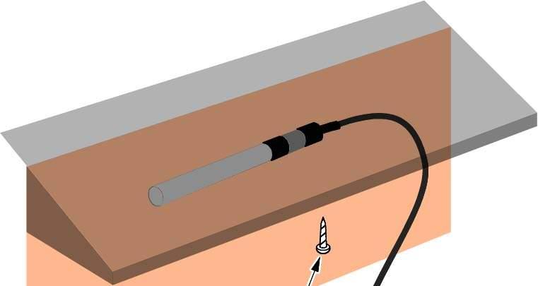
 JB-75 Junction Box (7")


4 Bylin Engineered Systems 4800 Golden Foothills Parkway, El Dorado Hills, CA Phone: Fax: STANDARD ROOF ICE MELT PANELS AND COMPONENTS RIM2-E Eave Cover & Base (up to 10 ft lengths) RIM2-V Valley Cover & Base (up to 10 ft lengths) RIM2-LPE Low Pitch Eave Cover & Base (up to 10 ft lengths) CCB Cable Cover Bracket (up to 10 ft lengths) RIM-S Snowmelt Cover & Base (up to 10 ft lengths) RIM-SC Snowmelt Concealed Panel (up to 10 ft lengths) RIM-C Channel Cover & Bottom (up to 10 ft lengths) ECC Eave Cable Cover (up to 10 ft lengths) JB-55 Junction Box (5 x5 ) JB-75 Junction Box (7 x5 ) GFS-PI Plug In Ground Fault Switch DSH Downspout Hanger EPEB2 Eave Panel End Bracket WSTK Splice Tee Kit WPCK-R Power Connection Kit RIM2 Install v13 Introduction Page 2 of 2 EN RaychemRIM2StandardInstallationManual IM H /16 4
5 Bylin Engineered Systems 4800 Golden Foothills Parkway, El Dorado Hills, CA Phone: Fax: RIM2 SYSTEM GENERAL PROCEDURES 1. Upon receipt of shipment: Immediately inspect packaging upon delivery. If there are any damaged packages, note on shipper s bill of lading and contact Bylin Engineered Systems (toll-free ) Identify and visually inspect all materials and compare with the packing list included with the shipment. Contact Bylin if there are any discrepencies. Review RIM2 System Layout Drawings with RIM2 panels identified, junction box locations for each section, and RTD temperature sensor locations. See sample layout if not supplied. 2. Setup access equipment (ladders, scaffolding, safety ropes, etc.) 3. Determine based on the RIM2 System Layout Drawings where the RIM2 panels are to be installed and the roof eave end conditions for those locations. RIM2 Install v13 General Procedures Page 1 of 1 EN RaychemRIM2StandardInstallationManual IM H /16 5
6 EN RaychemRIM2StandardInstallationManual IM H /16 6
7 EN RaychemRIM2StandardInstallationManual IM H /16 7


8 EN RaychemRIM2StandardInstallationManual IM H /16 8


9 EN RaychemRIM2StandardInstallationManual IM H /16 9

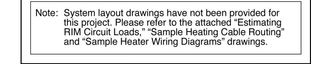
10 Bylin Engineered Systems 4800 Golden Foothills Parkway, El Dorado Hills, CA Phone: Fax: RIM2-V VALLEY BASE INSTALLATION 1. Install RIM2-V bases according to valley conditions and locations. A) Roof valley ends at heated inside eave corner B) Roof valley ends at unheated eave C) Roof valley ends at heated eave D) Roof valley transition E) Roof valley below eave In areas of the valley flashing where RIM2-V bases will be installed with adhesive, clear away all debris and carefully clean with a solvent such as denatured alcohol. Caution: Failure to position RIM2-V bases per instructions could cause melted snow to re-freeze at unheated areas, forming icicles and ice dams. 1A. Starting at the lower edge of the valley flashing at the roof eave, position the RIM2-V base 3 inches up the valley from the drip edge, continuing with additional RIM2-V bases. Watertight roof underlayment 3 (A. Roof valley ends at inside corner) RIM2 Install v13 RIM2-V Base Installation Page 1 of 3 EN RaychemRIM2StandardInstallationManual IM H /16 10

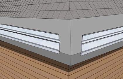
11 Bylin Engineered Systems 4800 Golden Foothills Parkway, El Dorado Hills, CA Phone: Fax: B. If the roof valley ends at an unheated roof eave, starting at the lower edge of the valley flashing at the roof eave, position the RIM2-V base 1 inch up the valley from the drip edge, continuing with additional RIM2-V bases. RIM2-V base on valley flashing Extend valley flashing at least 1 inch past the facia, forming a drip edge. Eave (B. Roof valley ends at unheated eave) 1 Eave 1C. Position RIM2-V base starting 3 inches from the RIM2-E base. If valley flashing is present with only one adjacent RIM2-E base, position the RIM2-V base on the opposite side of the flashing,. RIM2-V base on valley flashing. 3 Eave Install RIM2-V base 3 inches from the RIM-E base for cable routing. RIM2-E Base (C. Roof valley ends at heated eave end) 1D. Allow 1-2 inches between RIM2-V bases and at transition points for cable routing. RIM2-V base on valley flashing 1-2 At locations where a valley transitions at an angle, locate the RIM2-V base on the far side of the valley flashing (as shown) to allow cable routing. Allow 1-2 inch spacing between RIM2-V bases 1-2 (D. Roof valley transitions) RIM2 Install v13 RIM2-V Base Installation Page 2 of 3 EN RaychemRIM2StandardInstallationManual IM H /16 11
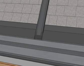
12 Bylin Engineered Systems 4800 Golden Foothills Parkway, El Dorado Hills, CA Phone: Fax: E. If RIM2-E bases are to be located above the RIM2-V base path, align the RIM2-V bases vertically below the RIM2-E base drip edge. To be installed later RIM2-E drip edge (E. Roof valley below eave) RIM-V 2. Apply a bead of adhesive along the entire length of each side of the bottom of the RIM2-V base and place it on the cleaned valley flashing. Starting at the lower end of the valley, position the RIM2-V base 1/8 inch from the flashing s center V-crimp to allow for later installation of RIM2-V cover panel. Allow 1-2 inch space between base sections. Use tape or other method to fasten RIM2-V base pieces in place until the adhesive sets (cure time will vary with temperature). Position and adhere the additional RIM2-V bases, cut to fit as needed. RIM2 Install v13 RIM2-V Base Installation Page 3 of 3 EN RaychemRIM2StandardInstallationManual IM H /16 12

13 Bylin Engineered Systems 4800 Golden Foothills Parkway, El Dorado Hills, CA Phone: Fax: RIM2-LPE LOW PITCH EAVE BASE INSTALLATION 1. Determine from the RIM2 System Layout Drawings where the RIM2-LPE Low Pitch Eave bottom with base attached is to be installed. On the roof eave, place the RIM2-LPE bottom directly at the end of the eave. Make sure there is a 1 inch gap from the end of the RIM2-LPE bottom and the start of the RIM2-LPE base for cable routing. Position the bottom piece with a 1/4 inch space between the eave fascia and the drip edge of the RIM2-LPE bottom. Position the next RIM2-LPE bottom directly against the previous RIM2-LPE bottom leaving no space in-between. Continue with the final RIM2-LPE bottom flush with the other end of the roof eave with a 1 inch gap from the end of the RIM2-LPE base to the end of the RIM2-LPE bottom. RIM2-LPE bottom RIM2-LPE base Leave 1/4 gap between RIM2-LPE bottom and fascia 2 1/2 to screw typ. 3 to screw typ. 2 ft typ. RIM2-LPE base has 1 gap to end of RIM-LPE bottom (both sides of roof eave) Eave Place next RIM2- LPE bottom piece directly against previous bottom piece Extend RIM2-LPE bottom all the way to eave end (base has 2 gap) 2. Using self-tapping, non-rusting, outdoor screws of appropriate length, screw down the RIM2-LPE bottom. Locate screws 2-1/2 inches in from the edge of the RIM2-LPE bottom, within 3 inches from the eave end, and on 2 foot centers. Apply caulking over screwheads to create a water-tight seal. At eave end: 2 1/2 1/4 3 2 typical 1 RIM2 Install v13 RIM2-LPE Base Installation Page 1 of 1 EN RaychemRIM2StandardInstallationManual IM H /16 13
14 EN RaychemRIM2StandardInstallationManual IM H /16 14
15 EN RaychemRIM2StandardInstallationManual IM H /16 15

16 EN RaychemRIM2StandardInstallationManual IM H /16 16


17 EN RaychemRIM2StandardInstallationManual IM H /16 17
18 EN RaychemRIM2StandardInstallationManual IM H /16 18
19 EN RaychemRIM2StandardInstallationManual IM H /16 19
20 EN RaychemRIM2StandardInstallationManual IM H /16 20
21 EN RaychemRIM2StandardInstallationManual IM H /16 21
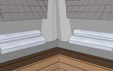
 RIM2-E Eave cover panel Heating cable 1.")

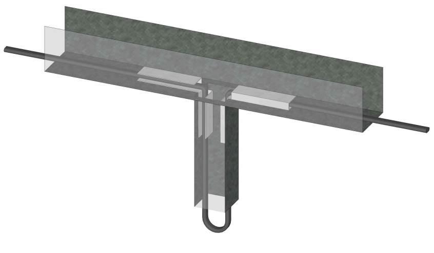
22 Bylin Engineered Systems 4800 Golden Foothills Parkway, El Dorado Hills, CA Phone: Fax: RIM2-E EAVE COVER PANEL & SPLICE COVER INSTALLATION 3 MAX typical 2 ft MAX typical (2 ft MAX) RIM2-E Eave cover panel Heating cable 1. Slip the RIM2-E cover panel at least 1 inch up under the roof material and hold it against the base drip edge. Using self-tapping, non-rusting, outdoor screws of appropriate length, screw the RIM2-E cover panel in place. Locate screws within 3 inches of the eave ends and on 2 foot centers. After securing the RIM2 panels, recheck the cover panel to verify that it is locked securely into place at the drip edge. RIM2 Install v13 RIM2-E Cover Installation Page 1 of 2 EN RaychemRIM2StandardInstallationManual IM H /16 22

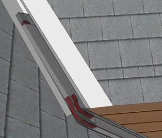
23 Bylin Engineered Systems 4800 Golden Foothills Parkway, El Dorado Hills, CA Phone: Fax: A. Where the roof eaves meet at a valley intersection, allow extra RIM2-E cover panel at corners for miter cuts. Trim the RIM2-E cover panel as needed around the RIM2-V cover panel. RIM2-V cover panel on valley flashing 1B. Notch RIM2-E cover as needed to route heating cable. RIM2-E cover panel over RIM2-E base Eave Eave 2. Continue installing RIM2-E cover panels allowing 1 inch spacing between covers. At the end locations, trim and fold RIM2-E cover panels as needed. 3. Apply a bead of adhesive along each side of the RIM2-E cover panel. Position the RIM2-E splice cover centered over the joint and slide it under the counter-flashing, locking it securely at the drip edge. Screw the RIM2-E splice cover in place with two self-tapping, non-rusting outdoor screws of appropriate length. Seal all joints with sealant. Refer to Temperature Sensor Installation to install RTD temperature splice covers. RIM2-E cover panel over base RIM2-E splice cover 1 spacing between covers RIM2 Install v13 RIM2-E Cover Installation Page 2 of 2 EN RaychemRIM2StandardInstallationManual IM H /16 23
24 Bylin Engineered Systems 4800 Golden Foothills Parkway, El Dorado Hills, CA Phone: Fax: RIM2-LPE LOW PITCH COVER PANEL INSTALLATION 1. Slip the RIM2-LPE cover panel at least 1 inch up under the roof material and hold it against the base drip edge. Using self-tapping, non-rusting, outdoor screws of appropriate length, screw the RIM2-LPE cover panel in place. Locate screws within 3 inches of the eave ends and on 2 foot centers. After securing the RIM2 panels, recheck the cover panel to verify that it is locked securely into place at the drip edge. Seal all joints with sealant. Slip RIM2-LPE cover up under the roof material and screw within 3 inches from the eave end and on 2 foot centers 3 to screw typ. 2 ft typ. Place next RIM2-LPE cover panel directly against previous cover panel Eave Extend RIM2-LPE cover panel all the way to eave end RIM2 Install v13 RIM2-LPE Cover Installation Page 1 of 1 EN RaychemRIM2StandardInstallationManual IM H /16 24
25 Bylin Engineered Systems 4800 Golden Foothills Parkway, El Dorado Hills, CA Phone: Fax: CCB CABLE COVER BRACKET INSTALLATION 1. Determine from the RIM System Layout Drawings where the CCB panels are to be installed. Install CCB in any areas where cable is exposed, if possible. Determine based on the direction of the cable s flat side whether to position CCB vertically or horizontally. Leave 1-2 inch gap on each end for cable routing, as needed. 1A. If fastened vertically on wall, position open side of CCB facing downward. 1B. To fasten with adhesive, clear away debris and carefully clean with a solvent such as denatured alcohol in areas where CCB IS to be installed. Place heating cable inside the CCB. Apply adhesive to the bottom of CCB, zig-zag edge to edge, and position CCB in place. Use tape or other method to fasten CCB in place until the adhesive sets (cure time depends on temperature.) Remove tape and verify CCB is well attached. 1C. To fasten with screws, place heating cable inside CCB, screw self-tapping, non-rusting, outdoor screws within 3 inches of ends and on 2 foot centers, at the CCB bend to avoid damaging cable inside. Seal with watertight seal. 1D. If cable twists, leave extra cable tucked into a loop at cable s turn point at the gap on either end. 2. Seal all joints with sealant. RIM Install v37 CCB Installation Page 1 of 1 EN RaychemRIM2StandardInstallationManual IM H /16 25
26 EN RaychemRIM2StandardInstallationManual IM H /16 26
27 EN RaychemRIM2StandardInstallationManual IM H /16 27
28 EN RaychemRIM2StandardInstallationManual IM H /16 28
29 EN RaychemRIM2StandardInstallationManual IM H /16 29
30 EN RaychemRIM2StandardInstallationManual IM H /16 30
31 EN RaychemRIM2StandardInstallationManual IM H /16 31
32 EN RaychemRIM2StandardInstallationManual IM H /16 32
33 Pentair Thermal Management LLC 4800 Golden Foothill Parkway, El Dorado Hills, CA Phone: / Fax: / info@bylinusa.com Installation Log Sheet - Raychem RIM/RIM2 Systems Application RIM System Project # RIM2 System Test Check List Test #1 - Prior to RIM Cover at J. Box Test #2 - After RIM Cover at J. Box Test #3 - Control Panel Terminal Blocks Reference End User Information Name Address Customer Information Name Address Contact Contact Phone 1 Phone 1 Phone 2 Phone 2 Mobile Mobile Other Other Visual Inspection Check for any signs of misinstallation or cuts in the cable jacket. Check that only approved components have been used. Verify that all install instructions were reviewed and followed. Heater Cable Model: For heater cable insulation resistance test, refer to drawing S-MGR-001 Meter Mfr Model # Volts Set Ckt # Reading Reading Reading Reading Ckt # Ckt # Ckt # (megohms) (megohms) (megohms) (megohms) MΩ MΩ MΩ MΩ MΩ MΩ MΩ MΩ MΩ MΩ MΩ MΩ MΩ MΩ MΩ MΩ MΩ MΩ MΩ MΩ MΩ MΩ MΩ MΩ Note: All circuits must be ground fault protected per the NEC. Visual inspection and insulation test performed by: Important Notice: Name Company Date To validate the heater cable 2-year warranty, the above tests must be completed on the installed heater cable, and the test results recorded & mailed, ed, or faxed to Pentair Thermal Management LLC. EN RaychemRIM2StandardInstallationManual IM H /16 33
ROOF ICE MELT (RIM) SYSTEM
 SYSTEM") Pipe Freeze Protection and Flow Maintenance ROOF ICE MELT (RIM) SYSTEM FOR CONCEALED ROOF & GUTTER DE-ICING Fire Sprinkler System Freeze Protection PRODUCT OVERVIEW The Raychem RIM System is our premier
Pipe Freeze Protection and Flow Maintenance ROOF ICE MELT (RIM) SYSTEM FOR CONCEALED ROOF & GUTTER DE-ICING Fire Sprinkler System Freeze Protection PRODUCT OVERVIEW The Raychem RIM System is our premier
ROOF ICE MELT (RIM2) SYSTEM
 SYSTEM") FOR CONCEALED ROOF & GUTTER DE-ICING PRODUCT OVERVIEW The Raychem RIM System is our premier engineered, aesthetically elegant, concealed roof & gutter de-icing solution to prevent ice dams, icicles, and
FOR CONCEALED ROOF & GUTTER DE-ICING PRODUCT OVERVIEW The Raychem RIM System is our premier engineered, aesthetically elegant, concealed roof & gutter de-icing solution to prevent ice dams, icicles, and
Radiant Edge LT TM Ice Melt System Installation and Operation Guide Version 1.4
 Radiant Edge LT TM Ice Melt System Installation and Operation Guide Version 1.4 From This... To This... Thermodynamics analyzed. Applied. Summit Ice Melt Systems, Inc. 2911 Lake Forest Road PO Box 6928
The IceFree Eave System
 Material Recycled Aluminum Alloy 6063 Temper - T5 Sizes. Sold in 5 panel extrusions. IceFree 8 Eave Panel (for eaves up to 12 deep) IceFree 12 Eave Panel (for eaves up to 18 deep) IceFree 18 Eave Panel
FTC-HST WARNING: CAUTION:
 FTC-HST XL-Trace, RaySol, and IceStop Splice/Tee Connection Kit Installation Instructions Description The Raychem FTC-HST is used with RaySol system heating cables to make splice connections (on slab bottoms
JB-RTD-STAND RTD PIPE STAND FOR COMBINATION POWER CONNECTION BOX AND ELECTRONIC CONTROLLER INSTALLATION INSTRUCTIONS
 JB-RTD-STAND RTD PIPE STAND FOR COMBINATION POWER CONNECTION BOX AND ELECTRONIC CONTROLLER INSTALLATION INSTRUCTIONS JB-RTD-STAND with Raychem heating cable DESCRIPTION The Raychem JB-RTD-STAND is a combination
KE-Series Constant-Wattage Heating Cable
 KE-Series Constant-Wattage Heating Cable Installation Instructions Read and understand this material before installing this heater. Failure to understand how to safely install the heater could result in
Gardian W51. Approvals
 Gardian W51 120 V pre-assembled electric heating cables for pipe freeze protection and roof & gutter de-icing Installation Instructions Description Gardian W51 120 V pre-assembled self-regulating heating
CLEANCUT CONVERTIBLE INSTALLATION GUIDE
 Page 1 of 16 CLEANCUT CONVERTIBLE INSTALLATION GUIDE COPYRIGHT 2016 SAFEWAY SAFETY STEP, LLC All Rights Reserved Reproduction or Distribution of this Installation Manual is Strictly Prohibited Page 2 of
CLEANCUT ULTRA-LOW INSTALLATION GUIDE
 Page 1 of 16 CLEANCUT ULTRA-LOW INSTALLATION GUIDE COPYRIGHT 2017 SAFEWAY SAFETY STEP, LLC (DBA CleanCut ) All Rights Reserved Reproduction or Distribution of this Installation Manual is Strictly Prohibited
JBM-100-LBTV2 Power Connection, Powered Splice, Dual Power Connection, or Splice with Junction Box
 JBM-100-LBTV2 Power Connection, Powered Splice, Dual Power Connection, or Splice with Junction Box Installation Instructions Description The JBM-100-LBTV2 is a Type 4X-rated connection kit. It is designed
C A Heating Cable Gland Kit
 C75-100-A Heating Cable Gland Kit Installation Instructions Description The C75-100-A is a NEMA 4X rated gland kit used to transition heating cables into a junction box when making connections off of a
ROOF AND GUTTER DE-ICING ICESTOP SYSTEM
 ROOF AND GUTTER DE-ICING ICESTOP SYSTEM This step-by-step design guide provides the tools necessary to design a Raychem IceStop roof and gutter de-icing system. For other applications or for design assistance,
INSTALLATIONGUIDE. HotSeam TM Overview ICE ROOF
 INSTALLATION GUIDE forfor HotSeam HotSeam Overview Exposed heat cables with glued down retention clips on metal roofs have been the conventional way to drain ice dams for many years. HotEdge s patented
IceStop System INSTALLATION AND OPERATION MANUAL FOR ROOF AND GUTTER DE-ICING SYSTEMS
 IceStop System INSTALLATION AND OPERATION MANUAL FOR ROOF AND GUTTER DE-ICING SYSTEMS THERMAL MANAGEMENT SOLUTIONS WWW.THERMAL.PENTAIR.COM Important Safeguards and Warnings WARNING: FIRE AND SHOCK HAZARD.
Roof and Gutter De-Icing
 Roof and Gutter 1. Pipe Freeze Protection and Flow Maintenance Introduction IceStop System This step-by-step design guide provides the tools necessary to design a Raychem IceStop roof and gutter de-icing
C Electrical Connection Kit
 1548-4010C Electrical Connection Kit For Use With Dekoron 2700 and 2300 Family of Heating Cables Installation Instructions Kit Description The Dekoron 1548-4010C electrical connection and end seal kit
Vertical Termination Part No: 3CGRVT 16 7/8" 18 Vent Pipe Extension Part No: 3CG18 9 7/8" Wall Hanger Part No: 3CGWH 7 7/8" 7 3/8"
 Corr/Guard Direct Vent Water Heater Vent/Air Intake System Installation and service must be performed by a qualified installer, service agency or the gas supplier. Installation must meet all state and
Data Sheet. Self regulating process heating tapes RS stock numbers ,
 Data Pack K Issued March 1997 232-3333 Data Sheet Self regulating process heating tapes RS stock numbers 379-889, 379-974 The information contained within this sheet regarding applications and installation
HotEdge Rail TM
 HotEdge Rail www.snoshield.com 888-976-6744 19 for HotEdge Rail HotEdge Rail is the first and only UL Listed roof edge ice melt system in the U.S. The revolutionary NEW patent-pending HotEdge Rail is engineered
Data Sheet. Self regulating heating tapes. RS stock numbers
 Data Pack K Issued September 2001 232-3125 Data Sheet Self regulating heating tapes RS stock numbers 379-312 The information contained within this sheet regarding applications and installation of RS WinterGard
HotEdge Rail TM
 HotEdge Rail TM www.hotedge.com 800.411.3296 19 DATA SHEET HotEdge Rail is the first and only UL Listed roof edge ice melt system in the U.S. The revolutionary NEW patent-pending HotEdge Rail is engineered
H908 WinterGard Plug-in Power Connection Kit with End Seal
 R R H908 WinterGard Plug-in Power Connection Kit with End Seal Installation Instructions Description The H908 is a plug-in, ground-fault-protected power connection kit for use with WinterGard H311, H611,
Table of Contents What to Expect with Your Installation. Ceiling Plate. Tools Needed.
 Table of Contents Congratulations on purchasing your new Casablanca ceiling fan! It will provide comfort and performance in your home or office for many years. This installation and operation manual contains
HWT-P HWAT POWER CONNECTION KIT WITH END SEAL INSTALLATION INSTRUCTIONS
 HWT-P HWAT POWER CONNECTION KIT WITH END SEAL INSTALLATION INSTRUCTIONS DESCRIPTION The Raychem HWT-P Power Connection and End Seal Kit is for use with HWAT heating cables. Materials for one power connection
IceStop System Installation and Operation Manual
 IceStop System Installation and Operation Manual For Roof and Gutter De-Icing WARNING: Fire and Shock Hazard. The IceStop roof and gutter de-icing system must be installed correctly to ensure proper operation
LED Flex Tube Assembly Guide
 LED Flex Tube Assembly Guide WARNING: NEVER APPLY POWER TO FLEX TUBE WHILE COILED!!! Please read entire guide before beginning assembly or installation. Licensed electricians should provide all electrical
HS-TSPLICE - HEATSHRINK TEE / SPLICE. Installation Instructions
 - HEATSHRINK TEE / SPLICE This kit is only for use with the following Drexan HeatTracer Self-Regulating heater products: PipeGuard Warm (PGW), MultiTrace (MT) and HotTape (HT). CAUTION: A ground fault
Table of Contents What to Expect with Your Installation. Tools Needed. Wall Control
 Table of Contents Congratulations on purchasing your new Casablanca ceiling fan! It will provide comfort and performance in your home or office for many years. This installation and operation manual contains
Table of Contents What to Expect with Your Installation. Tools Needed. Motor Housing.
 Table of Contents Congratulations on purchasing your new Casablanca ceiling fan! It will provide comfort and performance in your home or office for many years. This installation and operation manual contains
CEILINGS BACKSPLASHES WALLS PROJECTS INSTALLATION GUIDE.
 CEILINGS BACKSPLASHES WALLS PROJECTS INSTALLATION GUIDE Installation videos available online at: /videos Ceiling Components: A tin ceiling is comprised of two primary components and two optional components.
Table of Contents. What to Expect with. Mounting Options. Tools Needed. Wall Control
 Table of Contents www.casablancafanco.com What to Expect with Your Installation Congratulations on purchasing your new Casablanca ceiling fan! It will provide comfort and performance in your home or office
TT3000 and TT5000 Series
 TT3000 and TT5000 Series Bulk Sensing Cable Installation Instructions General Notes Do s and Don ts General Information These instructions detail techniques used to install TT3000 or TT5000 bulk sensing
FlexiPanel INSTALLATION PROCEDURES WITH MAINTENANCE AND TROUBLE SHOOTING GUIDE INSPECTION REPORT FORMS
 FlexiPanel INSTALLATION PROCEDURES WITH MAINTENANCE AND TROUBLE SHOOTING GUIDE INSPECTION REPORT FORMS FlexiPanel Vessel Heating System The following installation procedures are suggested guidelines for
Table of Contents. What to Expect with. Mounting Options. Tools Needed. Preparation. Wiring. Downrod.
 Table of Contents www.casablancafanco.com What to Expect with Your Installation Congratulations on purchasing your new Casablanca ceiling fan! It will provide comfort and performance in your home or office
Table of Contents What to Expect with Your Installation. Tools Needed. Wall Control
 Table of Contents Congratulations on purchasing your new Casablanca ceiling fan! It will provide comfort and performance in your home or office for many years. This installation and operation manual contains
SEPARATED COMBUSTION. General WARNING
 Form I-UD-V-SC (09-17) Obsoletes Form I-UD-V-SC (Version 05-17) APPLIES TO: Venting Requirements for Model UDAS and Model UDBS and Instructions for Combustion Air Inlet / Vent Terminal Options CC6 and
Standard Downrod for ceilings 8-10 feet high. Longer Downrod for ceilings 10 feet or higher
 Table of Contents www.casablancafanco.com To register your fan, please visit: www.casablancafanco.com/register What to Expect with Your Installation Save your receipt for proof of purchase. Ceiling Bracket??
Installation and Maintenance Instructions
 Commercial & Industrial Positive Pressure or Condensing AL 29-4C Stainless Steel High Challenge Special Gas Vent Also for Natural Draft Appliances 3",4",5",6",7",8",9",10" and 12" Diameter Special Gas
KR Series Air Defrost Unit Coolers Operating and Installation Manual
 KR Series Air Defrost Unit Coolers Operating and Installation Manual KR Air Defrost Unit Coolers (PN E108317_L) TABLE OF CONTENTS 1 RECEIPT OF EQUIPMENT... 2 1.1 INSPECTION... 2 1.2 LOSS OF GAS HOLDING
Curb Inlet Filter INSTALLATION MANUAL. Bio Clean Environmental Services, Inc. 398 Via El Centro Oceanside, CA 92058
 Curb Inlet Filter INSTALLATION MANUAL Bio Clean Environmental Services, Inc. 398 Via El Centro Oceanside, CA 92058 www.biocleanenvironmental.com p: 760.433.7640 f: 760.433.3176 INSTALLATION PROCEDURES
Tankless Water Heater Direct Vent Sweet Termination Installation Instructions
 Tankless Water Heater Direct Vent Sweet Termination Installation Instructions The Sweet Termination Direct Vent System is designed for use with the following models: RTG-74DV-1 RUTG-74DV -1 RMTG-74DV -1
SELF-REGULATING PIPE TRACING HEATER CABLE
 SELF-REGULATING PIPE TRACING HEATER CABLE Installation & Operation Manual TABLE OF CONTENTS GENERAL INFORMATION... 1 How Heating Systems Work...1 PRODUCT SELECTION... 1 RECEIPT & STORAGE... 1 Receipt...1
Electric Floor Warming Systems Installation and Operation Instructions. Mat Heating Systems and Cable Heating Systems. UL Listed for USA and Canada
 Electric Floor Warming Systems Installation and Operation Instructions Mat Heating Systems and Cable Heating Systems UL Listed for USA and Canada Thank you for your purchase of a Warming Systems electric
HotValley TM
 HotValley TM www.hotedge.com 800.411.3296 13 DATA SHEET HotValley creates wide melt path for snow melt water to prevent ice dam formations. It is recommended that HotValley be used in combination with
Installation Instructions PRO SERIES
 Installation Instructions PRO SERIES If you are a plumber installing this unit, please leave this owners manual & warranty card with the owner when you finish the installation. Thank You! DO NOT USE THIS
1SC-SSC Splice Connection Kit Installation Instructions
 1SC-SSC Splice Connection Kit Installation Instructions Description The 1SC-SSC is a NEMA 4 rated splice connection kit for use with Raychem 1SC30, 40, 50, 60, 70, 80 (-CT) and 1SC/H30, 40, 50, 60, 70,
Installation Instructions Built-In Dishwasher
 GE Consumer & Industrial Appliances Installation Instructions Built-In Dishwasher If you have questions, call 800.GE.CARES (800.432.2737) or visit our website at: www.ge.com BEFORE YOU BEGIN Read these
Garage Ventilation Installation Instructions
 Garage Ventilation Installation Instructions Parts List * Quantity Exterior Louver & Frame Kit 4 in. x 4 in. w/ Fasteners (Fastener shown as a) () Louver 4 in. x 8 in. w/ Fasteners (Fastener shown as a)
Installation Instructions. For the 18 Built-In Dishwasher and Front Color Panels
 Installation Instructions For the 18 Built-In Dishwasher and Front Color Panels Printed in USA 154232102 Before You Begin DO NOT INSTALL DISHWASHER UNTIL YOU HAVE READ ALL INSTRUCTIONS. FOR YOUR SAFETY,
Installation Guide. Beveled Stainless Steel Sinks K-3388 K-3387 K-3389 K A
 Installation Guide Beveled Stainless Steel Sinks K-3387 K-3388 K-3389 K-3391 1021992-2-A Tools and Materials Pencil and Marker Measuring Tape Drill Scissors Sealant Safety Glasses Keyhole/Compass or Saber
MNEFDD54 & MNBCDD54 GALVANIZED WALL FANS Installation, Operation, and Maintenance Instructions
 FARM PRODUCTS DIVISION MEMBER OF AMCA AMERICAN COOLAIR CORPORATION P.O. BOX 2300 JACKSONVILLE, FLORIDA 32203 PHONE (904) 389-3646 FAX (904) 387-3449 E-MAIL - fans@coolair.com MNEFDD54 & MNBCDD54 GALVANIZED
FLANGED CORR/GUARD CORR/GUARD INSTALLATION INSTRUCTIONS
 CORR/GUARD INSTALLATION INSTRUCTIONS This symbol on the nameplate means this product is listed by Underwriters Laboratories Inc. Tested to UL1738 / CAN / ULCS636-08 Listing No. MH26687 Testing No. 11EN
Prior to Installation: Inspect the sink prior to installation to make sure the sink has not been damaged during shipping Use the cut-out template prov
 INSTALLATION MANUAL Stainless Steel Farmhouse Kitchen Sink KHF200-30 / KHF200-33 / KHF200-36 KHF203-33 / KHF203-36 KHF204-33 www.kraususa.com I toll free: 1.800.775.0703 I 2016 Kraus USA Inc. Prior to
What to Expect with Your Installation. Tools Needed. 30 inches PA G E. To register your fan, please visit: 11 PA G E
 Table of Contents Tools Needed Mounting Options 1.888.227.2178 Ceiling Bracket 30 inches To register your fan, please visit: www.casablancafanco.com/register Wiring 11 Troubleshooting??? 15 14 1 13 Operation,
Electrical cable Water supply tube Fittings for tube Coupler Teflon tape. Hole saw min. 2½" bit
 Installation Parts and Tools Parts not Provided Electrical cable Water supply tube Fittings for tube Coupler Teflon tape Air gap Wire nuts for 6-gauge wiring Hose clamp ⅞" UL approved strain relief Electrical
SMALL DIAMETER CORR/GUARD & SLEEVED CORR/GUARD
 CORR/GUARD INSTALLATION INSTRUCTIONS This symbol on the nameplate means this product is listed by Underwriters Laboratories Inc. Tested to UL1738 / CAN / ULCS636-08 Listing No. MH26687 Testing No. 11EN
Installation Instructions
 Installation Instructions Self-Cleaning Radiant Electric Drop-In Range JDP47, JD968, JD900 If you have questions, call 1.800.GE.CARES or visit our website at: ge.com Before You Begin Read these instructions
SAFETY & COMFORT FOR THE HOME RESIDENTIAL MARKET U.S. PLUMBING CANADA PLUMBING AND ELECTRICAL
 SAFETY & COMFORT FOR THE HOME RESIDENTIAL MARKET U.S. PLUMBING CANADA PLUMBING AND ELECTRICAL THERMAL BUILDING SOLUTIONS WWW.PENTAIRTHERMAL.COM solutions to make a home winter safe PIPE FREEZE PROTECTION
How To: PREPARATION REPLACE A KITCHEN SINK
 Skill Level: INTERMEDIATE Give these projects a try if you're a confident DIYer with a good working knowledge of a variety of tools. They can take a day or more to complete. If you can build a birdhouse
INSTALL & USERS GUIDE
 Thanks so much for choosing my gutter guard! I designed it to fit your gutter, no matter what type of gutter and roof configuration you have. GUARANTEED! So don t return it if you think it won t fit. It
Kallista Bath Flip Drain
 P21586 Page 1 of 7 THANK YOU FOR CHOOSING KALLISTA We appreciate your commitment to Kallista quality products. Please take a moment to review this manual before you install your Kallista product. If you
60" Lyndon Patio. Instruction Manual Customer Service :30 AM to 5:00 PM EST, Monday - Friday A Kichler Decor ceiling fan
 60" Lyndon Patio TM 310140 A Kichler Decor ceiling fan Includes wall mount control system Kichler Lighting 7711 East Pleasant Valley Road P.O. Box 318010 Cleveland, Ohio 44131-8010 Instruction Manual Customer
Installation Instructions Built-In Dishwasher
 Installation Instructions Built-In Dishwasher If you have questions, call 800.GE.CARES (800.432.2737) or visit our Website at: GEAppliances.com. In Canada, please call 1.800.561.3344 or visit www.geappliances.ca
Hanson LED C e i l i n g F a n
 Hanson LED C e i l i n g F a n model no. 052-8398-2 Toll-free 1-866-827-4985 IMPORTANT: For your safety please read and understand this manual before installing or operating this product. OWNER S MANUAL
Technical Manual. VFD / Cabinet Heater Upgrade 110 VAC Heater to 12 VDC Heater. Provided by: Chart Inc.
 Technical Manual VFD / Cabinet Heater Upgrade 110 VAC Heater to 12 VDC Heater Provided by: Chart Inc. 407 7th Street NW New Prague, MN 56071 USA (800) 400-4683 Part Number 20977233 Rev. A 2016 Chart Inc.
Introduction The following illustrated instructions are a generic guide to the internal installation of Safety and Security Films.
 TECHNICAL BULLETIN Avery Dennison Interior Safety Films Installation Guide issued: 01/2018 Introduction The following illustrated instructions are a generic guide to the internal installation of Safety
INSTALLATION INSTRUCTIONS UNDERCOUNTER DISHWASHERS
 INSTALLATION INSTRUCTIONS UNDERCOUNTER DISHWASHERS VIKING 111 Front Street Greenwood, Mississippi 38930 USA (662) 455-1200 IMPORTANT - PLEASE READ AND FOLLOW Before beginning - please read these instructions
Installation Instructions
 GE Consumer & Industrial Appliances Installation Instructions Junction Box Cover Within this user bag, you will find a junction box cover and a #10 hex head screw used to attach the junction box cover
XAGA 550/550-L. Aerial Splice Closure. 1. General Description. 2. Warnings. 3. Cautions
 XAGA 550/550-L Aerial Splice Closure I N S T A L L A T I O N I N S T R U C T I O N S 1. General Description 1. This practice provides information regarding the description and use of the XAGA 550/550-L
HEATING CABLE RATINGS APPROVALS* Drexan Energy Systems, Inc. Kelowna, BC, Canada, V4V 1S5
 DREX0019 Division 1 Adapter Kit Single Cable These installation instructions are only for use with the following Drexan HeatTracer heater products: Self-Regulating (PipeGuard Warm (PGW), MultiTrace (MT)
Table of Contents What to Expect with. Tools Needed. Mounting Options. Wiring. Downrod. Canopy.
 Table of Contents Congratulations on purchasing your new Hunter ceiling fan! It will provide comfort and performance in your home or office for many years. This installation and operation manual contains
Frost Heave Protection System Installation and Operation Manual
 Frost Heave Protection System Installation and Operation Manual FHPC Constant Power Density Heating Cable Systems Thermal management solutions EN-RaychemFHPS-IM-INSTALL103 R1 WARNING: Fire and Shock Hazard.
Dishwasher. Installation manual DW60M9990AP
 Dishwasher manual DW60M9990AP DW9000M_DD68-00197B-00_EN.indd 1 6/1/2017 4:34:14 PM Contents Contents 3 What s included 3 requirements 7 Dimensions and specifications 9 Step-by-step installation 11 2 English
GWS. Venting Manual. Gas-Fired Water Boilers. Hazard definitions. Contents. Venting method definitions
 GWS Gas-Fired Water Boilers Venting Manual Hazard definitions Contents Page Hazards that will cause severe personal injury, death or substantial property damage. Hazards that can cause severe personal
IdealFILM. Do-It-Yourself Installation Manual
 IdealFILM Do-It-Yourself Installation Manual Comfortable Warm Floors Benefits of using RSG Idealfilm Heats from the floor up for better heat distribution throughout the room No dust or allergens blown
VENTILATION FAN. MFG Model : VFB80HLED2/VFB080C4L2 /VFB080C4LED2/ VFB100HLED2/VFB100C4LED1 READ AND SAVE THESE INSTRUCTIONS
 VENTILATION FAN MODEL 80HLED/80L/80LED/00HLED/00LED TABLE OF CONTENTS Package Contents General Safety Information 3 Preparation Assembly Instructions 5 New Construction 5 Existing Construction 6 Connect
Vent and air piped through a side wall (concentric termination)
") Vent and air piped through a side wall (concentric termination) Read before proceeding The vent piping operates with positive pressure. The vent piping must be completely sealed and securely supported.
Vent and air piped through a side wall (concentric termination) Read before proceeding The vent piping operates with positive pressure. The vent piping must be completely sealed and securely supported.
TS40 Product Assembly & Service Information Manual
 TS40 Product Assembly & Service Information Manual MODEL: SERIAL NUMBER(S): MANUFACTURE DATE: Please review all the information in this manual before attempting assembly and/or maintenance. ASSEMBLY FOR:
SEPARATED COMBUSTION WARNING
 CUSTOMER AGENCY PROCESS CQS CONVERGENT QUALITY SYSTEM PRODUCT WARRANTY START-UP Form I-SDH-V (Version.5) Obsoletes I-SDH-V (Version.4) Vent Installation Applies to: Venting Requirements for PREEVA Separated-Combustion
Lifetime Limited Warranty
 World Imports Lifetime Limited Warranty The retailer warrants the fan motor to be free from defects in workmanship and material present at time of shipment from the factory for a lifetime after the date
HEATRACE. Young Chang Silicone Ltd, Co. SELF-REGULATING PIPE TRACING HEATER CABLE. Installation, Operation & Maintenance Manual
 HEATRACE SELF-REGULATING PIPE TRACING HEATER CABLE Installation, Operation & Maintenance Manual Young Chang Silicone Ltd, Co. Contents I. General Information......3 1. How Heating Systems Work......3 II.
Installation Instructions
 Installation Instructions Electric Drop-In Range JDS28, JDP39 Questions? Call 800.GE.CARES (800.432.2737) or Visit our Website at: ge.com BEFORE YOU BEGIN Read these instructions carefully and completely.
TECK-40 Series 1000V Class Splice for 4/C Armored Teck Power Cables
 Product Installation Instructions TECK-0 Series 000V Class Splice for /C Armored Teck Power Cables Raychem Tyco Electronics - Energy 8000 Purfoy Road Fuquay-Varina, NC 756 PII-598 Rev AC The following
ALUMINUM. ELEVATED. CEDAR RENDITIONS DESIGN SERIES INSTALLATION INSTRUCTIONS
 ALUMINUM. ELEVATED. CEDAR RENDITIONS DESIGN SERIES INSTALLATION INSTRUCTIONS CEDAR RENDITIONS BY ROYAL 2 INSTALLATION INSTRUCTIONS TABLE OF CONTENTS Important Notes...5 Wall Preparation...7 Installation
Table of Contents. 1 M /11/13 Casablanca Fan Company What to Expect with Your Installation
 Table of Contents Congratulations on purchasing your new Casablanca ceiling fan! It will provide comfort and performance in your home or ofice for many years. This installation and operation manual contains
5LCM52XX Series Fan. Owner s Guide and Installation Manual. UL Model NO. : AC-552AL
 Owner s Guide and Installation Manual 5LCM52XX Series Fan UL Model NO. : AC-552AL Attach sales receipt to this card and retain as your proof of purchase DATE OF PURCHASE: MODEL NUMBER: RETAILER NAME: RETAILER
2 PREPARE THE OPENING
 Installation Instructions 27 & 30 Electric Built-In Wall Ovens Questions? Call 1.800.GE.CARES (1.800.432.2737) or visit www.geappliances.com In Canada, call 1.800.561.3344 or visit www.geappliances.ca
Raychem Heating System
 Raychem Heating System Tank Heater (H55207) Approvals F M APPROVED Ordinary and Hazardous Locations lass I, Div. 2, Groups B,, D lass II, Div. 1 & 2, Groups E, F, G lass III All hazardous location applications
Please Read and Save These Instructions.
 Page 1 of 8 RadonAway Ward Hill, MA. GP500 Fan Installation Instructions Please Read and Save These Instructions. DO NOT CONNECT POWER SUPPLY UNTIL FAN IS COMPLETELY INSTALLED. MAKE SURE ELECTRICAL SERVICE
SEPARATED COMBUSTION. General
 Form I-UD-V-SC (Version D) Obsoletes Form I-UD-V-SC (Version C) APPLIES TO: Venting Requirements for Model UDAS and Model UDBS and Instructions for Inlet / Vent Terminal Options CC6 and CC2 General This
NELSON HEAT TRACING SYSTEMS INSTALLATION
 DESCRIPTION The ALT-BY Tee Splice Connection Kit is constructed of cast aluminum for use with all versions of Nelson Heat Tracing Systems LT, CLT, HLT and NC heater cables. Compatible for use with any
Table of Contents What to Expect with. Mounting Options. Tools Needed. Downrod. Blades
 Table of Contents Congratulations on purchasing your new Hunter ceiling fan! It will provide comfort and performance in your home or office for many years. This installation and operation manual contains
Installation Instructions Built-In Dishwasher
 RINSE CHINA CRYSTAL SPEED CYCLE NORMAL WASH COOK WARE SELECTIONS ANTI BACTERIA START RESET ENHANCEMENTS DELAY HOURS ADDED HEAT PRE WASH HEATED DRY TO LOCK CONTROLS PRESS HEATED DRY FOR 3 SECONDS GE Consumer
V Refrigeration Module
 5800 230V Refrigeration Module Removal and Replacement Instruction Sheet 60-4702-062 Revision F, January 25, 2016 These instructions cover the 4700 and 5800 230V refrigerator module replacement. Before
Easy installation in both new construction and retrofit RN80L RN110L READ AND SAVE THESE INSTRUCTIONS INSTALLATION GUIDE
 READ AND SAVE THESE INSTRUCTIONS RN80L RN0L ULTRA Pro TM Ventilation Fan / Light / Night Light with ULTRAQuick TM Installation Technology INSTALLATION GUIDE Easy installation in both new construction and
SWIVEL HEAD WASTE AND OVERFLOW INSTALL
 SKU(s): 921385 SWIVEL HEAD WASTE AND OVERFLOW INSTALL BEFORE YOU BEGIN We recommend consulting a professional if you are unfamiliar with installing bathroom fixtures and plumbing. Signature Hardware accepts
ATCO How a Cooling Unit Works
 G A L V A N I Z E D Contents of this PDF How a Cooling Unit Works pages 1 2 pages 3 6 How a Cooling Unit Works RV refrigeration manufacturers have known the value of zinc protection for decades. In fact,
Destination Collection Whirlpool Bath Installation Instructions
 Tools you might need for proper installation Galvanized Nails or Screws Large Level Hammer or Screw Gun Shims Adhesive Thank you for purchasing Praxis Bathware. For best results, please read and follow
Innes. Instruction Manual A Kichler Decor ceiling fan. Includes our new TM
 Innes 300130 A Kichler Decor ceiling fan Includes our new CoolTouch Control System Looks permanent, but goes wherever you go! U.S. Patent Pending Kichler Lighting 7711 East Pleasant Valley Road P.O. Box