Model: Available in: Sapphire Black and Glacier White. 1 Series
|
|
|
- Elwin Evans
- 6 years ago
- Views:
Transcription
1
2 Model: Available in: Sapphire Black and Glacier White 1 Series
3 Table of Contents Product Image Table of Contents What is a Programmable Room Thermostat? Installation Procedure Mode Select Pairing the neohub Pairing the neostat V2 What is a Mesh Network? Approach Sensor Frost Protection Power ON/OFF Holiday Programming Optional Features Re-calibrating the Thermostat Error Codes Diagrams Factory Reset Mode 1 - Thermostat 10 Mode 2 - Time Clock 33 LCD Display Temperature Display Setting the Clock Setting the Comfort Levels Setting the Temperature Temperature Hold Locking/Unlocking the neostat LCD Display Setting the Switching Times Timer Override Optional Features Optional Features Table Time Clock Mode Wiring Diagram
4 What is a Programmable Room Thermostat? A programmable room thermostat is both a programmer and a room thermostat. A programmer allows you to set On and Off periods to suit your own lifestyle. A room thermostat works by sensing the air temperature, switching on the heating when the air temperature falls below the thermostat setting, and switching it off once this set temperature has been reached. So a programmable room thermostat lets you choose what times you want the heating to be on, and what temperature it should reach while it is on. It will allow you to select different temperatures in your home at different times of the day (and days of the week) to meet your particular needs and preferences. Setting a programmable room thermostat to a higher temperature will not make the room heat up any faster. How quickly the room heats up depends on the design and size of the heating system. Similarly reducing the temperature setting does not affect how quickly the room cools down. Setting a programmable room thermostat to a lower temperature will result in the room being controlled at a lower temperature, and saves energy. 3 Series
5 The way to set and use your programmable room thermostat is to find the lowest temperature settings that you are comfortable with at the different times you have chosen, and then leave it alone to do its job. The best way to do this is to set the room thermostat to a low temperature say 18 C, and then turn it up by 1 C each day until you are comfortable with the temperature. You won t have to adjust the thermostat further. Any adjustment above this setting will waste energy and cost you more money. You are able to temporarily adjust the heating program by overriding or using the temperature hold feature. These features are explained further on pages 17 and 18 of this manual. Programmable room thermostats need a free flow of air to sense the temperature, so they must not be covered by curtains or blocked by furniture. Nearby electric fires, televisions, wall or table lamps may also prevent the thermostat from working properly. 4
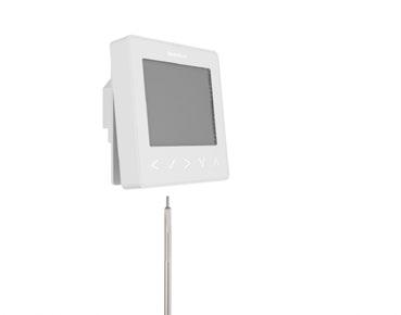
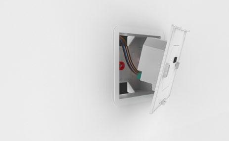
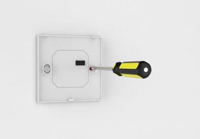
6 Installation Procedure Do Mount the thermostat at eye level. Read the instructions fully so you get the best from our product. Don t Do not install near to a direct heat source as this will affect functionality. Do not push hard on the LCD screen as this may cause irreparable damage. The neostat V2 is designed to be flush mounted and requires a back box of 35mm (minimum depth) to be sunk into the wall prior to installation. Step 1 Using a small screwdriver, slightly loosen the screw from the bottom face of the thermostat. Then carefully separate the front half from the back plate. Step 2 Place the thermostat front somewhere safe. Terminate the thermostat as shown in the diagrams on pages of this booklet. Note: For time clock wiring connections, terminate as shown on page 38. Step 3 Screw the thermostat back plate securely into the back box. Step 4 Clip the front of the thermostat onto the back plate, securing it in place with the retaining screw. 5 Series
7
8 Mode Select This neostat V2 can either be used as a thermostat or a time clock. Thermostat mode is the default setting. To change between thermostat or time clock modes, follow these steps. Use the Left / Right keys to scroll to... Press and hold the Tick button for 3 seconds... SETUP will be highlighted, now press and hold the tick key for 10 seconds... Use the Left / Right keys to scroll between modes... Mode 1 = Thermostat Mode 2 = Time Clock Press the Tick key to confirm selection... The neostat V2 will revert to the main display screen for the selected mode. For time clock mode instructions, first pair the time clock with the neohub as explained on page 8, then turn to page Series
9 Pairing the neohub To pair the neohub with the neoapp, follow these steps. Connect the neohub to your router with the Ethernet cable provided. Connect the power supply to the neohub. The router will automatically assign an IP address to the neohub, the Link LED will light up RED once the neohub has connected to your network. Once connected to the Heatmiser cloud server, the Link LED will turn GREEN. Connect your smartphone or tablet device to the same WiFi network as your router. Download the FREE Heatmiser neoapp from the Apple App Store, Google Play Store or Windows Phone App Store and register an account. Once you have registered your account, press Sign In, then press Add Location. Press the connect button on the neohub to add the location to your account. When successfully connected, enter a title for the location (e.g. Home). Pairing the neostat The next step is to join the neostat V2 to the neohub, we recommend joining the neostat V2 located nearest to the neohub first. To add a neostat V2, follow these steps; In the app, select ADD NEOSTAT, enter a preset or custom title, then press NEXT. You now have two minutes to join the neostat V2 to the neohub. On the neostat V2, use the Left / Right keys to select, press and hold Tick... SETUP will be highlighted, now press the tick key once... Feature 01 is displayed on screen. 8
10 Press the Tick key once again to pair the neostat to the neohub... The MESH symbol appears flashing on the display. When the neostat V2 successfully connects to the neohub the MESH symbol will be permanently displayed. Press ADD ANOTHER for addtional zones or press FINISH to complete setup. Please note, you only have to pair the hub to your account once. To pair any additional neostats, select ZONES, edit, then ADD ZONE. What is a Mesh Network NeoStats work using a mesh network, meaning neostats have the ability to send & receive signals via other thermostats on the network. This signal is relayed from one thermostat to another until it reaches its destination. This communication method extends the communication range whilst offering increased network stability when compared with standard RF thermostats. The Mesh symbol is shown when the device is communicating with the neohub, if the mesh symbol disappears this indicates connection to the neohub has been lost. Approach Sensor The neostat V2 uses proximity to detect when you are about to use the touch keys. As you approach the neostat V2, the touch keys and backlight will light up. This can be useful if you need to adjust the set temp or timer in a dark room. 9 Series

11 Mode 1 - Thermostat 10

12 Series
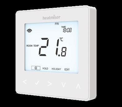
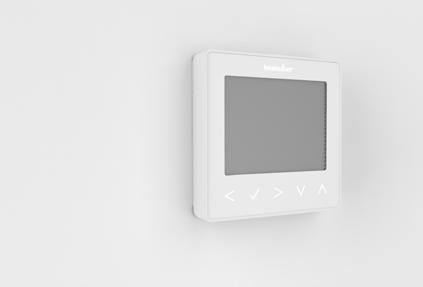
13 LCD Display 1. Mesh Symbol - Displayed when connected to the neohub. 2. Day Indicator - Displays the day of the week. 3. Frost Protection Displayed when frost protection is enabled. 4. Flame Symbol Displayed when the thermostat is calling for heat and flashes when optimum start is active. 5. Holiday Displayed when the thermostat is in holiday mode. 6. Floor Limit Symbol Displayed when the floor probe has reached the floor temperature limit configured in the setup menu. 7. Floor/Room Temp - Indicates the displayed sensor mode. 8. Set - Displayed when changes are being made to the current set point. 9. Program Indicator - Displayed during programming (6 level mode) to show which level is being altered. 10. Program Indicator - Displayed during programming (4 level mode) to show which level is being altered. 11. Main Menu - Displays which option is currently selected. 12. Keypad Lock Indicator Displayed when the keypad is locked. 13. Temperature Displays the current sensor temperature. 14. Temperature Format - Degrees Celsius or Fahrenheit. 15. Hold Left - Displayed when a temperature hold is active, the remaining time will be shown. 16. Time/Day/Month/Year - Displays when setting the Clock/Calendar or a Holiday Period. 12
14 Temperature Display The neostat V2 can be configured for different sensor options such as built in air sensor, floor sensor or both. The display will clearly indicate which sensor is being used by showing either Room Temp or Floor Temp before the actual temperature value. Room Temperature Floor Temperature When the neostat V2 is set to use both the air & the floor sensor, the room temperature will be displayed by default. To view the current floor temperature, press and hold the Left and Right arrow keys for 5 seconds, the floor temperature will then be displayed Series

15 Setting the Clock To set the clock, follow these steps. Use the Left / Right keys to scroll to... Press and hold Tick to turn off the display... Use the right arrow key to select CLOCK... Press Tick to confirm selection... Use Up / Down keys to set the year... Press Tick to confirm selection... Repeat the steps to set the Month, Date & Time... Press Tick to confirm the new clock settings... Use the down arrow to scroll to... Press Tick to turn the display on... Day Time 14
16 Comfort Levels Explained The neostat V2 offers three program mode options; Weekday/Weekend programming, 7 Day programming and 24 Hour programming. There is also the option to use the thermostat as a Non-Programmable thermostat. When thermostats are connected to the mesh network, the program mode for the system is configured by using the neoapp. The thermostat is supplied with comfort levels already programmed, but these can be changed easily. The default times and temperature settings are; 07:00-21 C (Wake) 09:00-16 C (Leave) 16:00-21 C (Return) 22:00-16 C (Sleep) If you only want to use 2 levels, you should program the unused levels to --:-- For Weekday/Weekend programming, the four comfort levels are the same for Mon-Fri, but can be different for Sat-Sun. For 7 Day programming each day of the week can have four different comfort levels. In 24 Hour mode all days are programmed with the same comfort levels. To program the comfort levels, use the Left / Right keys to scroll to EDIT... Press Tick to confirm selection... Use the Left / Right keys to select day / period of week (the selection will flash). Press Tick to confirm selection... WAKE will now flash and the current time and temperature setting will be shown. Press Tick to alter WAKE settings Series
17 Use the Up / Down keys to set the hours... Press Tick to confirm... Use the Up / Down keys to set the minutes... Press Tick to confirm... Use the Up / Down keys to set the temperature... Press Tick to confirm the settings... Press the right arrow key... LEAVE will now flash and the current settings will be displayed. Press Tick to alter LEAVE settings... Repeat these steps to set all comfort levels. For any unused periods set time to --:-- Use the Left / Right keys to scroll to DONE and press Tick... 16

18 Temperature Control The Up / Down keys allow you to adjust the set temperature... When you press either key, you will see the word SET and the desired temperature value. Use the Up / Down keys to adjust the SET value... Press Tick to confirm settings and return to the main display... Set Temperature Set Icon Note: This new temperature is maintained only until the next programmed comfort level. At this time, the thermostat will revert back to the programmed levels. 17 Series

19 Temperature Hold The temperature hold function allows you to manually override the current operating program and set a different temperature for a desired period. Use the Left / Right keys to scroll to HOLD... Press Tick to confirm selection... Use the Up / Down keys to set the desired Hold period... Press Tick to confirm selection... Use the Up / Down keys to set the desired Hold temperature... Press Tick to confirm selection... You will see the HOLD LEFT indication is displayed on screen. The time will countdown the set duration and then revert to the normal program. Hold Left Indicator Hold Time Remaining To cancel a temperature Hold, with hold selected on the main menu, press the tick key and then press tick again while Cancel is highlighted. 18
20 Locking the neostat V2 The neostat V2 has a keypad lock facility. To activate the lock follow these steps. Use the Left/Right keys to scroll to HOLD & press for 10 seconds... The display will show At this point enter a four digit pin number. Use the Up / Down keys to enter the first two digits... Press to confirm... Use the Up / Down keys to enter the second two digits... Press to confirm... The display will return to the main screen and display the keypad lock indicator... Note: The keypad lock indicator is only displayed when the lock is active. Unlocking the neostat V2 To unlock the neostat V2 press Tick once. The display will show 00:00 and you will need to enter the four digit pin number you set previously. Use the Up / Down and keys to enter the first two digits... Use the Up / Down and keys to enter the second two digits... The display will unlock and return to the main screen. 19 Series
.")
21 Frost Mode Use the Left / Right keys to scroll to the Power Icon... The frost icon will toggle ON/OFF each time Tick is pressed... In this mode, the neostat will display the frost icon and will only turn the heating ON should the room temperature drop below the set frost temperature (see page 23). If the heating is turned ON whilst in frost mode, the flame symbol will be displayed. To cancel the frost protect mode, navigate to the Power button again and press Tick. Frost Protection Mode Enabled 20


22 Power On/Off The heating is indicated ON when the flame icon is displayed. When the flame icon is absent, there is no requirement for heating to achieve the set temperature but the neostat remains active. To turn the neostat V2 off completely, scroll to the Power Icon and hold the Tick key for approximately 3 seconds until the display goes blank... The display and heating output will be turned OFF. To turn the thermostat back ON, press the Tick key once... Thermostat completely OFF Thermostat powered ON 21 Series
23 Holiday In thermostat mode, the holiday function reduces the set temperature in your home to the frost protection temperature setting (see page 23). The thermostat will maintain this temperature for the duration of the holiday and will then automatically return to the program mode on your return. In time clock mode, the holiday function maintains the timed output as OFF. Set a date & time for the holiday period to end, using the steps below; Use the Left / Right keys to scroll to HOLIDAY and press Tick... Use the Up / Down keys to set the year... Press Tick... Use the Up / Down keys to set the month... Press Tick... Repeat the steps to set the Date & Time... Pressing Tick to confirm selection... Note: The holiday period will start immediately, and will return to the normal program at the time & date you have configured. Use the Left / Right keys to scroll to HOLIDAY and press Tick... CANCEL will be highlighted, Press Tick to cancel... 22
24 Optional Settings Explained THE FOLLOWING SETTINGS ARE OPTIONAL AND IN MOST CASES NEED NOT BE ADJUSTED. Feature 01 Pairing To neohub: This function is used to connect the thermostat to the neohub. Feature 02 - Switching Differential: This function allows you to increase the switching differential of the thermostat. The default is 1 C which means that with a set temperature of 20 C, the thermostat will switch the heating on at 19 C and off at 20 C. With a 2 C differential, the heating will switch on at 18 C and off at 20 C. Feature 03 - Frost Protect Temperature: This is the temperature maintained when the thermostat is in Frost Mode. The range is C. The default is 12 C and is suitable for most applications. Feature 04 Output Delay: To prevent rapid switching, an output delay can be entered. This can be set from minutes. The default is 00 which means there is no delay. Feature 05 Temperature Up/Down Limit: This function allows you to limit the use of the up and down temperature arrow keys. This limit is also applicable when the thermostat is locked and so allows you to give others limited control over the heating system. Feature 06 Sensor Selection: On this neostat, you can select which sensor should be used. You can select between air temperature only, floor temperature, or both. When you enable both sensors, the floor sensor is used as a floor limiting sensor and is designed to prevent the floor from overheating. 23 Series
25 Feature 07 Floor Temp Limit: This function is available when mode 06 is set to 03 or 04. You can set a floor limiting temperature between C (28 C is the default setting). Note: Air Sensor only MUST NOT be used to control electric under-floor heating. Floor Sensor or Both should be used. Feature 08 Optimum Start: Optimum start will delay the start up of the heating system to the latest possible moment to avoid unnecessary heating and ensure the building is warm at the programmed time. The thermostat uses the rate of change information to calculate how long the heating needs to raise the building temperature 1 C (with a rate of change of 20, the thermostat has calculated the heating needs 20 minutes to raise the building temperature 1 C) and starts the heating accordingly. Feature 09 Rate of Change: Number of minutes for 1 C temperature rise. Feature 10 Not used on this model. Feature 11 Not used on this model. Feature 12 Program Mode: Non-Programmable, Weekday/Weekend (5/2), 7 Day Programming or 24 Hour. The thermostat offers three programming modes and the option of configuring it to work as a non-programmable thermostat. Weekday/ Weekend - allows you to program 4 comfort levels for the weekday and 4 different comfort levels for the weekend. 7 Day Program Mode - Each day has 4 comfort levels that can be programmed independently. 24 Hour Mode - All days are programmed the same and repeat continuously. Feature 13 - Temperature Format: This function allows you to select between C and F. 24

26 Adjusting the Optional Settings Use the Left / Right keys to scroll to... Press and hold the Tick button for 3 seconds... SETUP will be highlighted, now press the tick key once... Feature Number Setting Value Use the Up / Down keys to scroll through features... Use the Left / Right keys to adjust the setting within each feature... Press Tick to confirm and exit setup menu Series
27 Optional Settings - Feature Table FEATURE DESCRIPTION Pairing Switching Differential Frost Protection Temperature Output Delay Up/Down Temperature Limit Sensor Selection Floor Temperature Limit Optimum Start Rate of Change Not used on this model Not used on this model Program Mode Temperature Format SETTING Used to add zone to the neohub 00.5 = 0.5 C 01 = 1.0 C (Default) 02 = 2.0 C 03 = 3.0 C C (12 C = Default) Minutes (00 = Default) C (00 = Default) 00 = Built in Sensor (Default) 01 = Remote Air Sensor 02 = Floor Sensor Only 03 = Built in & Floor Sensor 04 = Remote Air & Floor Sensor 20 C - 45 C (28 C = Default) Hours (00 = Default) Minutes to raise by 1 C 00 = Non - Programmable 01 = Weekday/Weekend (Default) 02 = 7 Day Programming 03 = 24 Hour Mode 00 = C, 01 = F (00 = Default) 26
28 Re-calibrating the Thermostat If you need to re-calibrate the thermostat, follow these steps. Use the Left / Right keys to scroll to the... Press and hold Tick to turn the display OFF... Press and hold the Tick and Down keys together for 10 seconds... The current temperature will appear on the display. Use the Up / Down keys to configure the new temperature value... Press the Tick key to confirm the change and the display will go blank... Press the down arrow to highlight the... Press the Tick key once to turn the thermostat ON... Error Codes When terminated for thermostat operation the screen will display an error code if a fault is detected. E0 = The internal sensor has developed a fault. E1 = The remote FLOOR probe has not been connected. The remote FLOOR probe has not been wired correctly. The remote FLOOR probe is faulty. E2 = The remote AIR probe has not been connected. The remote AIR probe has not been wired correctly. The remote AIR probe is faulty. 27 Series
29 Wiring Diagram - neostat to Boiler S/L 230VAC RT2 RT1 - A2 A1 N L TO CONNECT BOILER CONSULT BOILER MAKERS DIAGRAM SWITCHED LIVE TO BOILER LIVE 230V SUPPLY IN NEUTRAL This product must only be installed by a qualified electrician and comply with local installation regulations. 28
30 Wiring Diagram - neostat to Boiler Voltfree 230VAC LR VOLT FREE TO BOILER LS RT2 RT1 - A2 A1 N L LS & LR ARE NORMALLY THE ROOM THERMOSTAT CONNECTIONS TO CONNECT BOILER CONSULT BOILER MAKERS DIAGRAM LIVE 230V SUPPLY IN NEUTRAL This product must only be installed by a qualified electrician and comply with local installation regulations. 29 Series
31 Wiring Diagram - neostat to Valve 230VAC RT2 RT1 - A2 A1 N L TO CONNECT BOILER CONSULT BOILER MAKERS DIAGRAM LS TO BOILER LR L N NEUTRAL LIVE 230V SUPPLY IN NEUTRAL HEATING VALVE LS & LR ARE NORMALLY THE ROOM THERMOSTAT CONNECTIONS This product must only be installed by a qualified electrician and comply with local installation regulations. 30
32 Wiring Diagram neostat to UH8 and Optional Remote Probe Connections 230VAC RT2 RT1 - A2 A1 N L FLOOR PROBE (Optional) L 1 2 E N SL REMOTE AIR PROBE (Optional) This product must only be installed by a qualified electrician and comply with local installation regulations. 31 Series
33 Factory Reset To reset the device to factory default settings, follow these steps: Use the Left / Right keys to scroll to... Press and hold Tick to turn the display OFF... SETUP will be highlighted... Press and hold the Tick key for 10 seconds... All of the icons on the display will appear for 2 seconds, then you will see the number 1 or 2 flashing. Use the Left / Right keys to scroll between modes (selection will flash)... Mode 1 = Thermostat Mode 2 = Time Clock Press the Tick key to confirm selection... The neostat will revert to the main display screen for the selected mode. Note: Factory reset will cancel all parameters that were entered during the set-up and pairing operations. These processes must be repeated after factory reset is completed. 32

34 Mode 2 - Time Clock Series
35 LCD Display 1. Mesh Symbol - Displayed when connected to the neohub. 2. Day Indicator - Displays the day of the week. 3. Holiday Displayed when the time clock is in holiday mode. 4. Set - Displayed when changes are being made to the current set point. 5. Program Indicator - Displayed during programming to show which level is being altered. 6. Main Menu - Displays which option is currently selected. 7. Keypad Lock Indicator Displayed when the keypad is locked. 8. Timer Status Displays the current state of the timed output. 9. Hold Left - Displayed when a timer hold is active, the remaining time will be shown. 10. Time/Day/Month/Year - Displays when setting the Clock/Calendar or a Holiday Period. 34
36 Setting the Switching Times To program the switching times, follow these steps. Use the Left / Right keys to scroll to EDIT and press Tick... Use the Left / Right keys to select day/period of the week... Press Tick to confirm selection... 1 will now flash and the current ON time will be displayed. The OFF time can be viewed by pressing the Down key... Select a switching time and press the Tick key... Use the Up / Down keys to select the ON time HOURS and press Tick... Use the Up / Down keys to select the ON time MINUTES... Press Tick to confirm selection... Use the Up / Down keys to select the OFF time HOURS and press Tick... Use the Up / Down keys to select the OFF time MINUTES... Press Tick to confirm selection... Press the Right arrow key... 2 will now flash and the current ON time will be displayed. Repeat the steps above to set all periods. For any unused periods enter -- : - When complete, use the Left / Right keys to scroll to DONE and press Tick to confirm all changes Series

37 Timer Override To override the timed output on, follow these steps. Use the Up / Down keys to set the override duration e.g. 02:00 hours... Press Tick to confirm settings and return to main display... Hold Left and the remaining time will now be displayed. HOLD LEFT Indicator Hold Time Remaining 36
38 Optional Features Explained Feature 01 Pairing To neohub: This function is used to connect the time clock to the neohub. Feature 02 - Weekday/Weekend (5/2), 7 Day Programming or 24 Hour Mode: The time clock offers three programming methods; Weekday/ Weekend (5/2) - Allows you to program 4 on/off switching times for the weekdays and 4 on/off switching times for the weekend. 7 Day Program Mode - Each day has 4 on/off switching times that can be programmed independently. 24 Hour Mode - All days are programmed with the same on/off switching times. Optional Settings - Feature Table FEATURE DESCRIPTION Pairing Program Mode SETTING Used to pair to the neohub 01 = Weekday/Weekend Programming (Default) 02 = 7 Day Programming 03 = 24 Hour Mode 37 Series
39 Wiring Diagram - Time Clock Mode 230VAC RT2 RT1 - A2 A1 N L VOLT FREE OUTPUT FOR 230V OUTPUT ON A2 LINK LIVE TO A1 LIVE 230V SUPPLY IN NEUTRAL This product must only be installed by a qualified electrician and comply with local installation regulations. 38
40 Notes 39 Model: Manual SeriesREF 39
41 Notes 40
42 Notes 41 Model: Manual SeriesREF 41
43 Notes 42
1254 669090 Or view")

44 Want More Information? Call our support team on: +44 (0) Or view technical specifications directly on our website: PDF FAQ Facebook: facebook.com/thermostats Rev.1.1
Model: 1 Series 12V. Available in: Sapphire Black and Glacier White
 Model: Available in: Sapphire Black and Glacier White 1 Series Table of Contents Product Image Table of Contents What is a Programmable Room Thermostat? Installation Procedure Mode Select Pairing the neohub
Model: Available in : Sapphire Black and Glacier White. 1 Series
 Model: Available in : Sapphire Black and Glacier White 1 Series Table of Contents Product Image 1 Frost Protection 20 Table of Contents 2 Power ON/OFF 21 What is a Programmable Room Thermostat? Installation
Table of Contents. Model: Series. Available in : Sapphire Black and Glacier White. Product Image. 20 Table of Contents.
 1 Model: Available in : Sapphire Black and Glacier White Table of Contents Product Image 1 Frost Protection 20 Table of Contents 2 Power ON/OFF 21 What is a Programmable Room Thermostat? Installation Procedure
12V. Model: Available in : Sapphire Black and Glacier White. 2 Series
 Model: Available in : Sapphire Black and Glacier White 2 Series Table of Contents Product Image 1 Locking/Unlocking the neostat 19 Table of Contents 2 Frost Protection 20 What is a Programmable Room Thermostat?
50110_HM-neoStat-2014_Layout 1 31/10/ :33 Page 1 neo
 neo Model: Available in : Sapphire Black and Glacier White 1 Wavin neo Table of Contents Product Image 1 Optional Features 19-22 Table of Contents 2 Re-calibrating the Thermostat 23 What is a Programmable
Table of Contents. Product Image Table of Contents What is a Programmable Room Thermostat? Installation Procedure
 1 Model: 1 Table of Contents Product Image Table of Contents What is a Programmable Room Thermostat? Installation Procedure 1 2 3-4 5-6 Mode Select Pairing the ProTouch iq Hub Pairing the ProTouch iq What
Table of Contents. Product Image 1 Locking/Unlocking the neoair 24 Table of Contents 2 Frost Protection 25 What is a Programmable Room Thermostat?
 Table of Contents Product Image 1 Locking/Unlocking the neoair 24 Table of Contents 2 Frost Protection 25 What is a Programmable Room Thermostat? 3-4 Power ON/OFF 26 Holiday Programming 27 Installation
Model: Slimline-N. 1 Slimline Series
 Model: Slimline-N Model: Slimline-N 1 Slimline Series Table of Contents Product Image Table of Contents What is a Programmable Room Thermostat? Installation Procedure LCD Display Operating Mode Setting
Table of Contents. SLIMLINE Series MODEL: SLIMLINE
 Table of Contents Product Image 1 Table of Contents 2 What is a Programmable Room Thermostat? 3-4 Installation Procedure 5-6 LCD Display 7-8 Setting the Clock 9 Temperature Display 10 Setting the Comfort
: PRT / PRT PRT / PRT-N1
 Model: PRT / PRT-N Model: PRT / PRT-N 1 Model: PRT / PRT-N Table of Contents Product Image Table of Contents What is a Programmable Room Thermostat? Installation Procedure LCD Display Setting the Clock
Underfloor Heating Programmable Thermostat
 Underfloor Heating Programmable Thermostat t: 093 4906 m: 0794 69635 w: www.gs-ufh.co.uk e: gs@warmfloors.co.uk POWER CLOCK H A DOWN UP TO CHANGE THE TIMINGS AT ANY STAGE DURING THE PROCESS YOU CAN PRESS
Model : PRT-EN Model: PRT-EN1
 Model: PRT-EN Model: PRT-EN 1 Model: PRT-EN Table of Contents Product Image Table of Contents What is a Programmable Room Thermostat? Installation Procedure LCD Display Setting the Clock Temperature Display
Model: PRT-TS / PRT-NTS
 Model: PRT-TS / PRT-NTS Model: PRT-TS / PRT-NTS 1 Model: PRT-TS / PRT-NTS Table Of Contents Product Image 1 Temperature Control 14 Table of Contents 2 Temperature Hold 15 What is a Programmable Room Thermostat?
Operating Instructions Model: PRT-RP Version 3. 05/11 Revision 2 Ref: PRTRP
 Operating Instructions Model: PRT-RP Version 3 05/11 Revision 2 Ref: PRTRP Contents Page What is a programmable thermostat? 2-4 Installation 5-6 Icons explained 6 Temperature Display 7 Setting the Clock
Model: Slimline-RF. 1 Slimline Series
 Model: Slimline-RF Model: Slimline-RF 1 Slimline Series Table of Contents Product Image 1 Holiday Programming 22 Table of Contents What is a Programmable Room Thermostat? 2 3-4 Setting the Hot Water Switching
Model: Slimline-B. Battery Series
 Model: Slimline-B Model: Slimline-B 2 Battery Series Table of Contents Product Image 1 Holiday Programming 20 Table of Contents 2 Frost Protection 21 What is a Programmable Room Thermostat? Installation
Model: PRT2-TS / PRT2-NTS EU. Model: Touch Duo
 Model: PRT2-TS / PRT2-NTS EU Model: Touch Duo 1 Model: Touch Duo 1 TouchScreen Series Series Table Of Contents Product Image 1 Temperature Control 14 Table of Contents 2 Temperature Hold 15 What is a Programmable
Model: Edge-HC. 1 edge-hc
 Model: Model: Edge-HC 1 edge-hc Table Of Contents Product Image Table of Contents Installation Procedure System Type LCD Display Power On/OFF Setting the Time & Date Mode Select Fan Speed Temperature Display
Model: Touch-RF. 1 Wireless Series
 Model: Touch-RF Model: Touch-RF 1 Wireless Series Table Of Contents Product Image 1 Locking the Keypad 18 Table of Contents 2 Temperature Control 19 What is a Programmable Room Thermostat? 3-4 Hot Water
PRT-TS WiFi PRT-TS WiFi
 Model: PRT-TS WiFi Model: PRT-TS WiFi 1 Model: PRT-TS WiFi Table Of Contents Product Image 1 Frost Protection 16 Table of Contents 2 Heating ON/OFF 16 What is a Programmable Room Thermostat? Installation
Model: Touch-RS. 1 Touch-RS
 Model: Touch-RS Model: Touch-RS 1 Touch-RS Table of Contents Product Image 1 Temperature Hold 15 Table of Contents 2 Holiday Programming 16 What is a Programmable Room Thermostat? Installation Procedure
Operating Instructions Model: PRT/HW - PRT/HW-N Version 3. 09/09 Revision 2 Ref: PRT/HW/NV3
 Operating Instructions Model: PRT/HW - PRT/HW-N Version 3 09/09 Revision 2 Ref: PRT/HW/NV3 Contents Page What is a programmable thermostat? 2-4 Installation 5-6 Icons explained 6 Temperature Display 7
Operating Instructions Model: PRT-TS WiFi RF. 01/13 Version 1 Ref: PRT-TSWIFI RF
 Operating Instructions Model: PRT-TS WiFi RF 01/13 Version 1 Ref: PRT-TSWIFI RF Contents Page Setting up your WiFi Thermostat 2-6 Remote Connection Setup 6-8 Pairing with the Receiver 8-12 Display Symbols
Operating Instructions Model : HC HC-N
 Operating Instructions Model : HC HC-N This product should be installed by a qualified electrician. Improper installation may result in injury, death or property damage. Contents Table Contents 1 What
Operating Instructions
 Operating Instructions Model : PRT-E / PRT-EN Installer Note: This thermostat is a combination model allowing you to choose between Floor Only or Air & Floor temperature control. Please see page 11 for
Uponor Comfort-E Thermostat Dig. Prog Set T-86 INSTALLATION AND OPERATION MANUAL
 Uponor Comfort-E Thermostat Dig. Prog Set T-86 INSTLLTION ND OPERTION MNUL 08 2017 Contents 1 Copyright and disclaimer...3 2 Preface...4 2.1 Safety instructions...4 2.2 Correct disposal of this product...4
Model: RT510RF. Installation Manual
 Model: RT50RF Installation Manual Contents Product compliance... 3 Safety Information... 3 Box content... 3 Introduction... 3 Features... Installation... 5. RXRT50 Receiver... 5 Button Description for
MAKING MODERN LIVING POSSIBLE. TP7001 Range Electronic 7 Day Programmable Room Thermostat. User Guide. Danfoss Heating
 MAKING MODERN LIVING POSSIBLE TP7001 Range Electronic 7 Day Programmable Room Thermostat Danfoss Heating User Guide TP7001 Electronic 7 Day Programmable Room Thermostat For a large print version of these
Drayton Digistat +3RF
 Drayton Digistat +3RF Programmable Room Thermostat Wireless 5-2 Day / 7 Day Model: RF701/22092 Power Supply: Battery - Thermostat Mains - Digistat SCR Invensys Controls Europe Customer Service Tel: 0845
Lyric T6 & T6R Smart Thermostat
 Lyric T6 & T6R Smart Thermostat EN User Guide Lyric T6 Programmable Thermostat Lyric T6R Wireless Programmable Thermostat Lyric T6 & T6R Smart Thermostat Features Connects to the Internet so you can control
CS027 User Instructions
 CS027 User Instructions Battery Powered 7 Day Programmable Room Thermostat Programmable room thermostats are widely recognised as one of the best ways in which to control central heating. The CS027 programmable
Digital Room Thermostat
 Digital Room Thermostat Instruction Manual Model No RT500 PRODUCT COMPLIANCE This product complies with the essential requirements of the following EC Directives: Electro-Magnetic Compatibility directive
C-Stat 17-ZW User Instructions
 C-Stat 17-ZW User Instructions 7 Day Wireless Programmable Room Thermostat and ASR-ZW Receiver Programmable room thermostats are widely recognised as one of the best ways in which to control central heating.
ECO AND DATE /06 ARTWORK DESCRIPTION. 22 page A6 : Saddle stitch (2-wire) 6 page : 4 colour : 170gsm Silk 18 page : 1 colour : 100gsm Silk
 6 page : 4 colour : 170gsm Silk 18 page : 1 colour : 100gsm Silk") DRAWING DETAILS PART NUMBER 42011077-103 ISS R1 ECO AND DATE 0024168 08/06 ARTWORK DESCRIPTION CM921 USER GUIDE BOOKLET (UK - English) DRAWN MKTING MF BM DATE 08/06 BOOKLET DETAILS SPECIFICATION COVER
DRAWING DETAILS PART NUMBER 42011077-103 ISS R1 ECO AND DATE 0024168 08/06 ARTWORK DESCRIPTION CM921 USER GUIDE BOOKLET (UK - English) DRAWN MKTING MF BM DATE 08/06 BOOKLET DETAILS SPECIFICATION COVER
ThermoPlus AS2-RF & ASR-RF Installation Instructions
 ThermoPlus AS2-RF & ASR-RF Installation Instructions The Horstmann ThermoPlus AS2-RF is a wireless room thermostat that has been designed to make its operation very simple for the householder. The built
CM707. Programmable Room Thermostat with Optimum Start, Optimum Stop and Delayed Start. User Guide
 CM707 Programmable Room Thermostat with Optimum Start, Optimum Stop and Delayed Start User Guide WHAT IS A PROGRAMMABLE ROOM THERMOSTAT? An explanation for householders... A programmable room thermostat
AUTO CM CM USER GUIDE
 1 2 3 4 5 6 7 AUTO CM701...2-6 CM707...7-11 USER GUIDE CM701 - USER GUIDE Description The Honeywell CM701 is a programmable room thermostat designed to control your heating system efficiently, providing
CM921 - User Guide 1 day Wireless Programmable Room Thermostat with LoT technology
 Description The Honeywell CM921 is a wireless programmable room thermostat designed to control you heating system efficiently, providing comfortable temperatures when you are at home and energy savings
CentaurStat 7 User Operating Instructions Central Heating Programmable Room ThermoStat
 CentaurStat 7 User Operating Instructions Central Heating Programmable Room ThermoStat The Centaurstat 7 is a programmable room thermostat that provides precise temperature control from a single point
Model: RT310. Installation Manual
 Model: RT310 Installation Manual Contents Product Compliance... 3 Safety Information... 3 Box Content... 3 Introduction... 4 Features... 5 Installation... 5 Button functions and keys... 7 Installer Mode...
Model: RT310i. Smartphone Controlled Thermostat. Installation Manual
 Model: RT310i Smartphone Controlled Thermostat Installation Manual Contents Product Compliance... 3 Safety Information... 3 Introduction... 4 Overview... 5 Box contents... 5 Features... 5 Connecting the
Digital Electronic Thermostat With RF
 Digital Electronic Thermostat With RF Instruction Manual Model No RT300RF PRODUCT COMPLIANCE This product complies with the essential requirements of the following EC Directives: Electro-Magnetic Compatibility
DIGISTAT OPTIMISER PROGRAMMABLE 7 DAY ROOM THERMOSTAT SYSTEM. Radio frequency controlled programmable room thermostat
 DIGISTAT OPTIMISER PROGRAMMABLE 7 DAY ROOM THERMOSTAT SYSTEM Radio frequency controlled programmable room thermostat FOR GREENSTAR 25 HE and GREENSTAR 30 HE MODELS Hol Man Auto Day SIGNAL HEATING ON OVERRIDE
ESRTPRF. Wireless Programmable Room Thermostat, with Delayed & Optimum Start. User and Installation Instructions M/A MANUAL
 M/A MANUAL ESRTPRF Wireless Programmable Room Thermostat, with Delayed & Optimum Start User and Installation Instructions INDEX User Instructions What is a Programmable Room Thermostat? 1 Introduction
Model: RT310RF. Installation Manual
 Model: RT310RF Installation Manual Contents Product Compliance... 3 Safety Information... 3 Box Content... 3 Introduction... 4 Features... 5 Installation... 5 Button functions and keys... 7 Installer mode...
Battery Powered Electronic Programmable Room Thermostat Cat. No. TRT035. Operating & Installation Instructions
 Battery Powered Electronic Programmable Room Thermostat Cat. No. TRT035 Operating & Installation Instructions What is a programmable room thermostat?... an explanation for householders A programmable room
Battery Powered Electronic Programmable Room Thermostat
 Battery Powered Electronic Programmable Room Thermostat Cat. No. TRT035 Operating & Installation Instructions What is a programmable room thermostat?...an explanation for householders A programmable room
Heating is great when you control it. USER MANUAL. Wireless Programmable Room Thermostat. Model No.: LS Scan for App
 Heating is great when you control it. USER MANUAL Wireless Programmable Room Thermostat Model No.: LS99111010 Scan for App Contents 1. Overview... 01 2. System Installation... 02 2.1 Install and Wiring
Why Vaillant? Because there s smart and then there s vsmart. Vaillant vsmart. The USER Guide
 Why Vaillant? Because there s smart and then there s vsmart Vaillant vsmart The USER Guide Allow me to introduce myself... What s in the box? Saving energy has never been so easy. Designed to work harmoniously
User Manual THR870CUK Programmable Thermostat
 User Manual UK Programmable Thermostat 50051984-001 Rev. A WARNING: This product must be correctly installed and configured to work properly (see pages 20-31). If you are not experienced in wiring electrical
DIGISTAT PROGRAMMABLE 24 HOUR ROOM THERMOSTAT SYSTEM. Radio frequency controlled programmable room thermostat.
 ROOM THERMOSTAT SYSTEM Radio frequency controlled programmable room thermostat. LARGE RECEIVER: 24CDi, 26CDi Xtra, 28CDi, 35CDi Mk I and 35CDi Mk II SMALL RECEIVER: 24i Junior, 28i Junior and Si Mk II
Elegance. SMT-700 User manual. Ver
 Elegance SMT-700 User manual Ver 3.0. 0807 Congratulations on the purchase of your new Thermostat! Your new air conditioning system thermostat has been built using the best components and design philosophy
User Manual THR842DUK Wireless Digital Thermostat
 User Manual THR842DUK Wireless Digital Thermostat 50051983-001 Rev. A WARNING: This product must be correctly installed and configured to work properly (see pages 12-23). If you are not experienced in
Type UCG/UDG. English...1 Français...7 Español Up button. OK button. Down button
 USER MANUAL Type UCG/UDG 57116D 06/12 (MBC) 1.10 2012 OJ Electronics A/S...1 Français...7 Español... 14 Type UCG/UDG Contents Introduction...1 First Time Settings...1 Ground Fault Circuit Interrupter (GFCI)...1
CoziStat. 1. Introduction and Brief Description COZISTAT INSTALLATION I NSTRUCTIONS &OPERATING MANUAL
 COZISTAT INSTALLATION I NSTRUCTIONS &OPERATING MANUAL CoziStat 1. Introduction and Brief Description The CoziStat is an easy-to-use, programmable thermostat with digital display. CoziStat can be used with
User Guide Y9420H Sundial RF 2 Pack 2
 PLEASE RESPECT YOUR ENVIRONMENT! Take care to dispose of this product and any packaging or literature in an appropriate way WHAT IS A PROGRAMMER?...an Explanation for Householders (as recommended by the
SAT-3 Room Temperature Controller
 SAT-3 Room Temperature Controller USER S OPERATING INSTRUCTIONS Contents Introduction 5 Features Summary 5 Operation 7 On/Off 7 Room Temperature Adjustment 7 Operating Mode Selection 8 Fan Speed Selection
MCD User Manual
 6759 08/5 ALA MCD5-999 User WWW.COMFORTHEAT.COM.AU < Contents > Contents Menu Overview................ 3 Introduction.................. Startup Wizard /2.............. 5 Startup Wizard 2/2..............
Smart thermostat with Humidification/De-humidification control
 x Smart thermostat with Humidification/De-humidification control Enter/Confirm Scroll Right = Increase Left = Decrease Back/Cancel TABLE OF CONTENTS Everyday Use 1. Adjusting Temperature...3 2. Adjusting
RF Programmable Room Thermostat User Instructions
 ESRTP4RF RF Programmable Room Thermostat User Instructions Thank you for choosing ESi Controls. All our products are tested in the UK so we are confident this product will reach you in perfect condition
User start guide Connected wireless room thermostat Logic Combi C / Vogue Gen 2 Combi Logic Max Combi C / Vogue Max Combi Vogue Combi C / Logic Combi
 User start guide Connected wireless room thermostat Logic Combi C / Vogue Gen Combi Logic Max Combi C / Vogue Max Combi Vogue Combi C / Logic Combi Contents Introduction... Ideal Touch kit contents...
MAKING MODERN LIVING POSSIBLE RET2000 B/M/MS. Electronic digital thermostat with LCD User Guide. Danfoss Heating
 MAKING MODERN LIVING POSSIBLE Danfoss Heating RET2000 B/M/MS Electronic digital thermostat with LCD User Guide For a large print version of these instructions please call Marketing on 0845 121 7400. Danfoss
Vokèra OpenTherm 711 with external sensor connected
 Vokèra OpenTherm 711 with external sensor connected Setup guide to using the OpenTherm Control with an external weather compensation sensor fitted. If you are unsure if an external sensor is fitted check
GreenCon On/Off Room Thermostat
 Description Features: Scandinavian design with white backlight; User-friendly interactive interface; Room temperature display and settings; 12 or 24 hour clock display and settings; Three-speed manual/automatic
GreenCon On/Off Room Thermostat
 Description Features: Scandinavian design with white backlight; User-friendly interactive interface; Room temperature display and settings; 12 or 24 hour clock display and settings; Three-speed manual/automatic
Programmable Thermostat
 Set & $ave Programmable Thermostat Installation and Operation Manual English Model 44360 Form# 42710-01 20091204 2009 Hunter Fan Co. 2 Table of Contents Important Information... 5 Tools... 6 Uninstalling
CRX Single Zone Wireless Controller. Installation and User Guide. 1. Getting to know your CRX2 wireless controller
 Please read this guide carefully and retain for future use and maintenance. CRX2-01 Single Zone Wireless Controller Installation and User Guide 1. Getting to know your CRX2 wireless controller An illustration
Programmable Thermostat with Plug in RF Boiler Control Model: ST620VBC INSTRUCTION MANUAL
 Programmable Thermostat with Plug in RF Boiler Control Model: ST620VBC INSTRUCTION MANUAL PRODUCT COMPLIANCE SALUS Controls Plc hereby declares that the radio equipment type 868Mhz is in compliance with
TB8220U Commercial Programmable Thermostat OWNER S GUIDE
 TB8220U Commercial Programmable Thermostat OWNER S GUIDE 63-2643 Contents Features... 3 Main Screen Selections... 4 Programming Heating and Cooling Schedule... 6 Operating the Thermostat... 10 Replacing
4iE Smart WiFi Thermostat Operating Guide
 4IE-01-XX-01/4IE-01-XX-02 4iE Smart WiFi Thermostat Operating Guide See reverse for Installation Guide Smartphone control Use your smartphone, tablet or computer to control your heating online Self-adjusting
SmartVent. Digital Controller User Guide Manual. NZ s Home Ventilation Specialists
 SmartVent NZ s Home Ventilation Specialists Digital Controller User Guide Manual www.smartvent.co.nz Introducing... SmartVent Digital Control Panel 12x2 LCD Display with Backlight On/Off Button Button
ST9400S User Guide. 1 Day Programmer, 2 channel With Boiler Service Reminder / Shut-down Feature
 PLEASE RESPECT YOUR ENVIRONMENT! Take care to dispose of this product and any packaging or literature in an appropriate way WHAT IS A PROGRAMMER?...an Explanation for Householders (as recommended by the
- Brochure D 542. Introduction. Features. tekmarnet 4 Thermostat /05. 5 Data Brochure Control settings wiring instructions
 - Brochure tekmarnet 4 Thermostat 542 D 542 06/05 1 Information Brochure Choose controls to match application Application Brochure Design your mechanical applications 2 3 Rough In Wiring Rough-in 4 Wiring
Stylish Thermostats For Modern Living
 Stylish Thermostats For Modern Living Domestic Heating Control Systems Dial Type Thermostats Stylish Dial Type Thermostats These thermostats are used in conjunction with a separate programmer. Headline
AQUATROL Zone Synchronizing Universal Injection/Mixing Boiler Reset Controls AQ252
 AQUATROL Zone Synchronizing Universal Injection/Mixing Boiler Reset Controls AQ252 USER OPERATION AND MAINTENANCE WARNING Risk of electrical shock. Can cause severe injury, property damage or death. Only
TPOne-B. Electronic Programmable Room Thermostat. Installation Guide. Danfoss Heating
 TPOne-B Electronic Programmable Room Thermostat Danfoss Heating Installation Guide TPOne is an intelligent programmable heating control made easy. TPOne includes features which are designed to save energy.
Cat No. 099A. Digital Programmable Thermostat for Weekday/Weekend Setting. User Maunal
 Cat No. 099A Digital Programmable Thermostat for Weekday/Weekend Setting User Maunal TABLE OF CONTENT 1 INTRODUCTION. 2 2 INSTALLATION. 4 3 SETTING CLOCK. 11 4 SETTING PROGRAM...12 5 SLEEP OPERATION MODE
Thermostats & smart controls. neohub+ UNDERFLOOR HEATING HEAT PUMPS SOLAR THERMAL
 Thermostats & smart controls neohub+ UNDERFLOOR HEATING HEAT PUMPS SOLAR THERMAL GS UFH s thermostat range controls with area zoning can save up to 40% on energy bills.* *When compared to an unzoned radiator
User Manual THR872CUK Wireless Programmable Thermostat
 User Manual THR872CUK Wireless Programmable Thermostat 50051985-001 Rev. A WARNING: This product must be correctly installed and configured to work properly (see pages 20-31). If you are not experienced
IDEAL E-NERGY Thermostat Touch type User Manual
 67800 03/18 (JRK) IDEAL E-NERGY Thermostat Touch type 203250 User Manual WWW.MFH-SYSTEMS.COM Contents Menu Overview............... 3 Introduction................. 4 Startup Wizard 1/2.............. 5 Startup
The easier, smarter heating system. Multi-zone heating made easy. User guide Setup and control
 The easier, smarter heating system Multi-zone heating made easy User guide Setup and control Getting to know the Wiser system Wiser system Smart heating for your home Wiser is designed to be simple to
Digital Electronic Thermostat With RF
 RT300RF Manual:89 6/7/10 12:52 Page 1 Digital Electronic Thermostat With RF Instruction Manual Model No RT300RF 2 RT300RF Manual:89 6/7/10 12:52 Page 2 2 RT300RF INSTRUCTION MANUAL RT300RF Manual:89 6/7/10
Installation and user manual
 Installation and user manual Please read carefully and retain for future reference Models EcoHeat: C3, C5, C6, C8, C9, C11, C12 Rev.1_09-07-15 Page 1 Table of Contents 1 IMPORTANT: WARNINGS 1.1 GENERAL
SAT- 3 Installation Setup Guide
 SAT- 3 Installation Setup Guide Date: 4 February 2016 Issue: 2 Applies to: SAT- 3 room temperature controller, part number 201-000- 146 Contents 1. Quick Start Guide...2 1.1. General... 2 1.1.1. Installation
Product Manual SZ1009
 Product Manual SZ1009 Conventional Heating & Cooling Thermostats with Heat Pump Mode Communicating Thermostats Description The SZ1009 is a microprocessor-based mable thermostats designed for conventional
irad Wireless Controller
 irad Wireless Controller The irad Wireless Controller is a wireless (433MHz) programmable thermostat giving high precision room temperature control. It also had a seven day programmer with up to six temperature
Vokèra OpenTherm 711 without external sensor connected
 Vokèra OpenTherm 711 without external sensor connected Setup guide to using the OpenTherm Control without an external weather compensation sensor fitted. If you are unsure if there is an external sensor
ATC32U03 igate Communicating, Programmable Thermostat
 ATC32U03 igate Communicating, Programmable Thermostat User Manual 97B0055N02 Rev.: 11/3/17 Table of Contents Section Title Page Menu Navigation Shortcuts 3 1.0 Operating Mode Selection 3 2.0 Temperature
User Manual. Dryer Controller M720
 User Manual Dryer Controller M720 Hardware version 1.00 Software version 1.00 Preliminary version Manual M720 Dryer controller Page 1 of 42 Document history Preliminary version: - Created in April, 2009
The Vitro-i. Radiant / Convector Combination Heater. Instructions for Operation and Installation
 E1400250 The Vitro-i Radiant / Convector Combination Heater Instructions for Operation and Installation (Read these instructions carefully and retain for further reference.) Models: Vitro-i 750 Black Vitro-i
MC200. Users Instructions. HEATING DIVISION Hort Bridge Ilminster, Somerset TA19 9PS Tel: Fax:
 MC200 Users Instructions BSI Registered Firm HEATING DIVISION Hort Bridge Ilminster, Somerset TA19 9PS Tel: 01460 53535 Fax: 01460 52341 FM 414 Ind. & Comm. Air Heaters; Air Moving Equipment; Flues & Chimneys;
SAS6000UTK-7 UNIVERSAL THERMOSTAT
 SAS6000UTK-7 UNIVERSAL THERMOSTAT Used with Single Stage, Multi-Stage, Heat pump Installation and operation instructions SPECIFICATION: Power Supply Dual Power 24VAC (18-30VAC,50/60Hz) or Battery Powered
User Guide for EHE & EHE Programmable Room Thermostat
 User Guide for EHE0200153 & EHE0200154 Programmable Room Thermostat Description The EHE0200153 & EHE0200154 are programmable room thermostats designed to control your heating system efficiently, providing
- Data Brochure tekmarnet 4 Thermostat 542e
 - Data Brochure tekmarnet 4 Thermostat 542e D 542e 03/08 1 Information Brochure Choose controls to match application 2 Application Brochure Design your mechanical applications 3 Rough In Wiring Rough-in
MAKING MODERN LIVING POSSIBLE. CP715Si. Electronic 2-Channel Common Timebase Programmer for Heating and Hot Water. User Guide.
 MAKING MODERN LIVING POSSIBLE CP715Si Electronic 2-Channel Common Timebase Programmer for Heating and Hot Water Danfoss Heating User Guide CP715Si Electronic 2-Channel Common Timebase Programmer for Heating
Peak Partners Web-Programmable Thermostat Homeowner s Manual. Look inside for a complete guide to the setup and operation of your new thermostat.
 Peak Partners Web-Programmable Thermostat Homeowner s Manual Look inside for a complete guide to the setup and operation of your new thermostat. Table of Contents Step 1: Getting Started...4-6 A. Thermostat
Programmable Interactive User Manual
 67504B 02/16 (ALA) DH E RT 102/BW Programmable Interactive User Manual www.schluter.com 1. Contents 2. Menu Overview..............3 3. Introduction................ 4 4. General Operation............5 4.1.Navigation
IT801 Thermostat. User s Manual. The complete guide to the set up and operation of your new smart Wi-Fi thermostat.
 IT801 Thermostat User s Manual The complete guide to the set up and operation of your new smart Wi-Fi thermostat. The smart Wi-Fi thermostat system learns your comfort preferences, then finds opportunities
For Quick Set-Up go to Page 14
 Talking Thermostat Model VT3000 Guide SmartWay Solutions, Inc. US Patent 6,608,560 & 7,62,253 For Quick Set-Up go to Page 4 Model VT3000, a universal thermostat for use on most Gas or Electric, Conventional
Thermotouch Dual Dual Control Thermostat
 5245 / 5245W / 5246 / 5246W Thermotouch Dual Dual Control Thermostat Installation & User Guide January 2018 Search for MyThermotouch to download the free app U N D E R F L O O R H E A T I N G C O N T R