Slim Multisensor PST02-A/B/C
|
|
|
- Delphia Preston
- 5 years ago
- Views:
Transcription

1 Slim Multisensor PST02-A/B/C Concurrent multi-channel support reduces external interference. Better RF range, improve about 10 meters in indoor. Support 100 Kbps transmit speed, speed up communication. Function Compare A/B/C PIR Door/Window Temperature Illumination PST02-A V V V V PST02-B V V V PST02-C V V V The slim multisensor PST02 has PIR, door/window, temperature and illumination, 4 sensors function in one, based on Z-Wave TM technology. It is the Z-Wave TM plus product, it support the security, OTA... Those newest features of the Z-Wave TM technology. Z-Wave TM is a wireless communication protocol designed for home automation, specifically to remotely control applications in residential and light commercial environments. The technology uses a low-power RF radio embedded or retrofitted into home electronics devices and systems, such as lighting, home access control, entertainment systems and household appliances. This product can be included and operated in any Z-Wave TM network with other Z-Wave TM certified devices from other manufacturers and/or other applications. All non-battery operated nodes within the network will act as repeaters regardless of vendor to increase reliability of the network. Add to/remove from Z-Wave TM Network There are two tamper keys in the device, one is in the back side, another is in the front side. Both of them can add, remove, reset or association from Z-Wave TM network. In the first time, add the device into the Z-Wave TM network. First, make sure the primary controller is in the add mode. And then power on the device, just take out the insulation Mylar in the back side of the device. The device will auto start the NWI (Network Wide Inclusion) mode. And it should be included in 5 seconds. You will see the LED light ON one second. The device adopt the Z-Wave TM 500 series chip, when your Z-Wave TM network system is all made by Z-Wave TM 500 series devices. The network system will have the advantages as below. 1
2 Notice: Including a node ID allocated by Z-Wave TM Controller means Add or Inclusion. Excluding a node ID allocated by Z-Wave TM Controller means Remove or Exclusion. to this group. And each group support 8 nodes maximum. Function Add Remove Reset Association Description 1. Have Z-Wave TM Controller entered inclusion mode. 2. Pressing tamper key three times within 1.5 seconds to enter the inclusion mode. 3. After add successful, the device will wake to receive the setting command from Z-Wave TM Controller about 20 seconds. 1. Have Z-Wave TM Controller entered exclusion mode. 2. Pressing tamper key three times within 1.5 seconds to enter the exclusion mode. Node ID has been excluded. Notice: Use this procedure only in the event that the primary controller is lost or otherwise inoperable. 1. Pressing tamper key four times within 1.5 seconds and do not release the tamper key in the 4 th pressed, and the LED will light ON. 2. After 3 seconds the LED will turn OFF, after that within 2 seconds, release the tamper key. If successful, the LED will light ON one second. Otherwise, the LED will flash once. 3. IDs are excluded and all settings will reset to factory default. 1. Have Z-Wave TM Controller entered association mode. 2. Pressing tamper key three times within 1.5 seconds to enter the association mode. Note: The device support 2 groups. The group 1 is for receiving the report message, like triggered event, temperature, illumination etc. The group 2 is for light control, the device will send the Basic Set command Failed or success in add/remove the node ID can be viewed from Z-Wave TM Controller. Notice 1: Always RESET a Z-Wave TM device before trying to add it to a Z-Wave TM network Notice 2: When the device into NWI mode, the sensor functionality will useless. The NWI mode will timeout after 30 seconds. You can press the tamper key 3 times to abort the NWI mode. Z-Wave TM Notification After the device adding to the network, it will wake-up once per day in default. When it wake-up it will broadcast the Wake Up Notification message to the network, and wake-up 10 seconds for receive the setting commands. The wake-up interval minimum setting is 30 minutes, and maximum setting is 120 hours. And the interval step is 30 minutes. If the user want to wake-up the device immediately, please remove the front cover, and press the tamper key once. The device will wake-up 10 seconds. Z-Wave TM Message Report When the PIR motion triggered or the door/windows triggered, the device will report the trigger event and also report the battery status, temperature and illumination level. In default the device will using Notification Report to represent the trigger event, it can be changed to Sensor Binary Report by setting the configuration NO. 7 Bit4 to 1. 2
3 * Motion Report: When the PIR motion detected, the device will unsolicited to send the report to the nodes in the group 1. Notification Report (V4) Notification Type: Home Security (0x07) Event: Motion Detection, Unknown Location (0x08) Sensor Binary Report (V2) Sensor Type: Motion (0x0C) Sensor Value: 0xFF * Door/Window Report: When the door/window state changed, the device will unsolicited to send the report to the nodes in the group 1. Notification Report (V4) Notification Type: Access Control (0x06) Event: Door/Window is open (0x16) Door/Window is closed (0x17) Sensor Binary Report (V2) Sensor Type: Door/Window (0x0A) Sensor Value: 0x00 is closed, 0xFF is opened. * Tamper Report: Both the 2 tamper keys are pressed over 5 seconds. The device will into the alarm state. In that state, if any one of the tamper keys be released, the device will unsolicited to send the report to the nodes in the group 1. Notification Report (V4) Notification Type: Home Security (0x07) Event: Tampering. Product covering removed (0x03) Sensor Binary Report (V2) Sensor Type: Tamper (0x08) Sensor Value: 0xFF * Temperature Report: When the PIR motion detected or the door/window state changed, the device will unsolicited to send the Sensor Multilevel Report to the nodes in the group 1. Sensor Type: Temperature (0x01) Note: To disable this functionality by setting the configuration N0.5 bit5 to 1. *** Temperature differential report *** This function default is enabled, to disable this function by setting the configuration NO.21 to 0. In the default, when the temperature is changed to plus or minus one degree Fahrenheit (0.56 degree Celsius), the device will report temperature information to the nodes in the group 1. The device will measure the temperature in every one minute. And if the temperature is over 140 degree Fahrenheit (60 degree Celsius), the device will always report in each measurement. Caution 1: Enable this functionality, it will cause the PIR Motion to disable detection when the temperature measurement. In other words, The PIR motion will blind one second in every one minute. * Illumination Report: When the PIR motion detected or the door/window state changed, the device will unsolicited to send the Sensor Multilevel Report to the nodes in the group 1. Sensor Type: Luminance (0x03) Note: To disable this functionality by setting the configuration N0.5 bit4 to 1. *** Illumination differential report *** This function default is disabled, to enable this function by setting the configuration NO.22 not to zero. 3
4 Enable this functionality, the device will measure the illumination in every one minute. And if the illumination is changed to plus or minus the value (setting by the configuration NO.22), the device will report illumination information to the nodes in the group 1. Caution 1: Enable this function will reduce the battery life about 15% ~ 20%. And another issue is setting the differential value too small, it will cause report too frequency, shorter the battery life more. Propose the setting differential value should not small than 10. Caution 2: If the configuration No.4 is setting to 0 or 100, this functionality is useless. Caution 3: Enable this functionality, it will cause the PIR Motion to disable detection when the illumination measurement. In other words, The PIR motion will blind one second in every one minute. * Timing Report: Beside the event triggered could report message, the device also support the timing unsolicited report of the status. Battery level report: Every 6 hours report once in default. It could be changed by setting the configuration NO. 10. Low battery report: When the battery level is too low, every 30 minutes will report once. Door/window state report: Every 6 hours report once in default. It could be changed by setting the configuration NO. 11. Illumination level report: Every 6 hours report once in default. It could be changed by setting the configuration NO. 12. Temperature report: Every 6 hours report once in default. It could be changed by setting the configuration NO. 13. Notice: The configuration NO. 10, 11, 12 and 13 could be setting to zero to disable the auto report. And the configuration NO. 20 could change the tick interval, the default value is 30, if setting to 1, that means the minimum auto report interval will be one minute. And please notice if setting this value to zero, that means disable all of the timing report except the low battery detection. Power Up Procedure * Battery Power Check When the device power up, the device will detect the power level of the battery immediately. If the power level is too low, the LED will continue flash about 5 seconds. Please change another new battery. * PIR Warm Up When the device power on, the PIR need to warm up before the operation. The warm up time about 1 minute, the LED will flash in every 2 seconds. After finish the procedure the LED will light ON three times. * NWI When the device power on, the device will check is it already adding to the network? If doesn't, it will auto start the NWI mode. The LED will flash in every second and continue 30 seconds. Until timeout or the device successful to inclusion by controller. The use can presses the tamper key 3 times to abort the NWI mode. * Wake When the device power on, the device will wake about 20 seconds. In this duration, the controller can communicate with the device. Normally the device is always sleeping to save the battery energy. Over The Air (OTA) Firmware Update The device support the Z-Wave firmware update via OTA. Before starting the procedure, please remove the front cover of the device. Otherwise the hardware check will be failed. Let the controller into the firmware update mode, and then press the front tamper key once to start the update. After finish the firmware download, the LED will start flash in every 0.5 second. At that time, please don't remove the battery, otherwise it 4
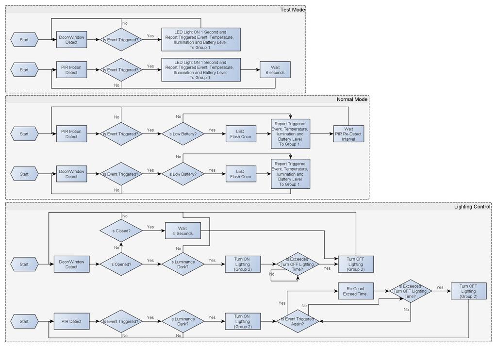
5 will cause the firmware broken, and the device will no function. After the LED stop flash, it is recommended that the user power up the device. Caution: After remove the battery, please wait about 30 seconds, and then re-install the battery. Security Network The device support the security function. When the device included with a security controller, the device will auto switch to the security mode. In the security mode, the follow commands need using Security CC wrapped to communicate, otherwise it will not response. COMMAND_CLASS_BATTERY COMMAND_CLASS_NOTIFICATION_V4 COMMAND_CLASS_ASSOCIATION_V2 COMMAND_CLASS_CONFIGURATION COMMAND_CLASS_SENSOR_BINARY_V2 COMMAND_CLASS_SENSOR_MULTILEVEL_V5 COMMAND_CLASS_WAKE_UP_V2 Function DIP Switch There is one function DIP switch in front of the device. Remove the front cover in the right top of the PCB, and also has mark M1 and M2 for two switch. Notice: PST02-C don't have DIP switch in hardware. M1 M2 Description ON ON Test Mode and OTA mode. ON OFF Normal Mode. OFF ON Normal Mode. OFF OFF Customer Mode. According to the configuration setting NO. 5 to set the operation mode. Operation Mode There are two modes Test and Normal. Test Mode is for the user test the sensor function when installation. Normal Mode for the normal operation. When the event triggered, normally the LED won't indicated, unless the battery is in the low level, the LED will flash once. But in the Test Mode the LED also will light ON one second. When the event triggered, the device will report the messages to the nodes in the group 1. The messages also include the battery level, the temperature and the illumination level. The user can switch the report by setting the configuration NO. 5 bit4 (illumination) and bit5 (temperature), and the configuration NO. 7 bit6 (battery). When the event triggered, if the environment luminance is less than the setting of the value of the configuration NO. 4, the device will emit the signal to turn ON the lighting equipment, those nodes are in the group 2. And delay a while to turn OFF the lighting equipment. The delay time is setting by the configuration NO. 9. The PIR motion re-detected interval, in the Test Mode fixed to 6 seconds. In the Normal Mode, it according to the setting of the configuration NO. 8. Notice: When the tamper key of the back side is released, the device always in the Test Mode, no matter the DIP switch setting. 5
6 6
7 Battery Installation When the device report the low battery message. The user should replace the battery to new one. The battery type is CR123A, 3.0V. The way to open the front cover please follow below steps. 1. Using a tool to press the 1-1 position, to release the cover. 2. Hold the front cover and pull back 3. Hold the front cover and pull up Choosing a Suitable Location Replace the new battery and install the cover back. 1. Put the front cover bottom to 1-1, and press down. 2. Push the front cover top to The recommended mounting height is 160cm 2. Don't let the device facing the window or the sunlight. 3. Don't let the device facing the source of heat. For instance the heater or the air-condition. 7
8 Installation 1. In the first time, add the device into the Z-Wave TM network. First, make sure the primary controller is in the inclusion mode. And then power on the device, just take out the insulation Mylar in the back side of the device. The device will auto start the NWI (Network Wide Inclusion) mode. And it should be included in 5 seconds. You will see the LED light ON one second. After finish the test and decide to fix, then you can remove tape A, and mounting the sensor by using tape B. The tamper key will pressed and let the sensor enter normal mode. 2. Let the controller associate with the device into the first group, any light switch that intend to be turned on when the device trig please associate with the device into the second group. 3. In the accessory pack. There are two type of double coated tape, one is thicker (hereinafter referred to as A tape) and another is thinner (hereinafter referred to as B tape), you can use A tape for the test at the beginning. The right way for A tape installation is stick it to the position below tamper key. The thicker tape won't let the tamper key pressed, so the sensor will enter the test mode, You may test if installed position is good or not by this way. Z-Wave Configuration Settings Notice: * All of the configuration, the data size is 1. * The configuration mark with star(*), means after the remove the setting still keep, don't reset to factory default. Unless the user execute the RESET procedure. * The reserve bit or not supported bit is allowed any value, but no effect. 8
9 2 3 (*) Basic Set Level PIR Sensitivity 0xFF All Light Threshold Setting the BASIC command value to turn on the light. The 0xFF(-1) means turn on the light. For dimmer equipment 1 to 100 means the light strength. 0 means turn off the light. PIR sensitivity settings. 0 means disable the PIR motion. 1 means the lowest sensitivity, 99 means the highest sensitivity. High sensitivity means can detected long distance, but if there is more noise signal in the environment, it will re-trigger too frequency. Setting the illumination threshold to turn on the light. When the event triggered and the environment illumination lower then the threshold, the device will turn on the light. 0 means turn off illumination detected function. And never turn on the light. 1 means darkest. 99 means brightest. 100 means turn off illumination detected function. And always turn on the light. Notice: In none test mode, only the value in 1 to 99 will enable the illumination detected function and update the illumination value. 5 (*) Operation Mode 0 All Operation mode. Using bit to control. Bit0: Reserve. Bit6: Reserve. Bit1: 1 means test mode, 0 means normal mode. Notice: This bit only effect by the DIP Switch setting to customer mode, otherwise it decides by DIP Switch setting to Test or Normal Mode. Bit2: Disable the door/window function. (1:Disable, 0:Enable) Bit3: Setting the temperature scale. 0: Fahrenheit, 1:Celsius Bit4: Disable the illumination report after event triggered. (1:Disable, 0:Enable) Bit5: Disable the temperature report after event triggered. (1:Disable, 0:Enable) Bit7: Disable the back key release into test mode. (1:Disable, 0:Enable) 9
10 6 (*) Mult- Sensor Function Switch 4 All 1 Multisensor function switch. Using bit to control. Bit0: Disable magnetic integrate illumination to turn ON the lighting nodes in the association group 2. (1:Disable, 0:Enable) Bit1: Disable PIR integrate Illumination to turn ON the lighting nodes in the association group 2. (1:Disable, 0:Enable) Bit2: Disable magnetic integrate PIR to turn ON the lighting nodes in the association group 2. (1:Disable, 0:Enable) (Default is Disable) Bit3: When Bit2 is 0 (Enable), Are the device and the lighting in the same room? 0: In the same room(default), 1: In the different room. Notice: If this bit is 1, it is recommended also set the Bit1 to 1, cause the PIR triggered, doesn't mean the people in that room. Bit4: Disable delay 5 seconds to turn off the light, when door/window closed. (1:Disable, 0:Enable) Bit5: Disable auto turn off the light, after door/window opened to turn on the light. (1:Disable, 0:Enable) Notice: If bit2 is zero, this setting is useless. Bit6: Reserve. Bit7: Reserve. Notice: If the configuration No.9 is zero, this setting is useless. 7 (*) Customer Function 4 All Bit0: Reserve. 1 Bit7: Reserve. Customer function switch, using bit control. Bit1: Enable sending motion OFF report. (0:Disable, 1:Enable) Note: Depends on the Bit4, 0: Report Notification CC, Type: 0x07, Event: 0xFE 1: Sensor Binary Report, Type: 0x0C, Value: 0x00 Bit2: Enable PIR super sensitivity mode. (0:Disable, 1:Enable) Bit3: Disable send out BASIC OFF after door closed. (1:Disable, 0:Enable) Bit4: Notification Type, 0: Using Notification Report. 1: Using Sensor Binary Report. Bit5: Disable Multi CC in auto report. (1:Disable, 0:Enable) Bit6: Disable to report battery state when the device triggered. (1:Disable, 0:Enable) 10
11 PIR Re- Detect Interval Time Turn Off Light Time Auto Report Battery Time Auto Report Door/Windo w State Time ~ In the normal mode, after the PIR motion detected, setting the re-detect time. 8 seconds per tick, default tick is 3 (24 seconds). Setting the suitable value to prevent received the trigger signal too frequently. Also can save the battery energy. Notice: If this value bigger than the configuration setting NO. 9. There is a period after the light turned off and the PIR not start detecting. After turn on the lighting, setting the delay time to turn off the lighting when the PIR motion is not detected. 8 seconds per tick, default tick is 4 (32 seconds). 0 means never send turn off light command. The interval time for auto report the battery level. 0 means turn off auto report battery. The default value is 12. The tick time can setting by the configuration No.20. The interval time for auto report the door/window state. 0 means turn off auto report door/window state. The default value is 12. The tick time can setting by the configuration No Auto Report Illumination Time Auto Report Temperatur e Time Auto Report Tick Interval Temperature Differential Report xFF 0x7F The interval time for auto report the illumination. 0 means turn off auto report illumination. The default value is 12. The tick time can setting by the configuration No.20. The interval time for auto report the temperature. 0 means turn off auto report temperature. The default value is 12. The tick time can setting by the configuration No.20. The interval time for auto report each tick. Setting this configuration will effect configuration No.10, No.11, No.12 and No.13. Caution: Setting to 0 means turn off all auto report function. The temperature differential to report. 0 means turn off this function. The unit is Fahrenheit. Enable this function the device will detect every minutes. And when the temperature is over 140 degree Fahrenheit, it will continue report. Enable this functionality will cause some issue please see the detail in the Temperature Report section. 11
: 868.40 MHz, 869.")
, Z-Wave Supported Command Class COMMAND_CLASS_ZWAVEPLUS_INFO_V2 COMMAND_CLASS_BATTERY COMMAND_CLASS_NOTIFICATION_V4 COMMAND_CLASS_ASSOCIATION_V2 COMMAND_CLASS_CONFIGURATION")
12 22 Illumination Differential Report 0 0x63 The illumination differential to report. 0 means turn off this function. The unit is percentage. Enable this function the device will detect every minutes. Enable this functionality will cause some issue please see the detail in the Illumination Report section. Specifications Power by CR123A lithium battery. Signal (Frequency): MHz, MHz(EU), MHz, MHz(US), 922~927 MHz(JP/TW), MHz, MHz(ANZ), MHz(RU), MHz(IN), MHz(IL), Z-Wave Supported Command Class COMMAND_CLASS_ZWAVEPLUS_INFO_V2 COMMAND_CLASS_BATTERY COMMAND_CLASS_NOTIFICATION_V4 COMMAND_CLASS_ASSOCIATION_V2 COMMAND_CLASS_CONFIGURATION COMMAND_CLASS_MANUFACTURER_SPECIFIC_V2 COMMAND_CLASS_VERSION_V2 COMMAND_CLASS_SENSOR_BINARY_V2 COMMAND_CLASS_SENSOR_MULTILEVEL_V5 COMMAND_CLASS_WAKE_UP_V2 COMMAND_CLASS_ASSOCIATION_GRP_INFO COMMAND_CLASS_POWERLEVEL COMMAND_CLASS_DEVICE_RESET_LOCALLY COMMAND_CLASS_MULTI_CMD COMMAND_CLASS_SECURITY COMMAND_CLASS_FIRMWARE_UPDATE_MD_V2 COMMAND_CLASS_MARK COMMAND_CLASS_BASIC Range: Minimum 30 meters indoor, 70 meters outdoor line of sight. Operating Temperature: -10 o C ~ 40 o C For indoor use only. Specifications subject to change without notice due to continuing product improvement. FCC ID: RHHPST02 12
13 FCC Interference Statement This equipment has been tested and found to comply with the limits for a Class B digital device, pursuant to Part 15 of the FCC Rules. These limits are designed to provide reasonable protection against harmful interference in a residential installation. This equipment generates, uses and can radiate radio frequency energy and, if not installed and used in accordance with the instructions, may cause harmful interference to radio communications. However, there is no guarantee that interference will not occur in a particular installation. If this equipment does cause harmful interference to radio or television reception, which can be determined by turning the equipment off and on, the user is encouraged to try to correct the interference by one of the following measures: Reorient or relocate the receiving antenna. Increase the separation between the equipment and receiver. Connect the equipment into an outlet on a circuit different from that to which the receiver is connected. Consult the dealer or an experienced radio/tv technician for help. Warning Do not dispose of electrical appliances as unsorted municipal waste, use separate collection facilities. Contact your local government for information regarding the collection systems available. If electrical appliances are disposed of in landfills or dumps, hazardous substances can leak into the groundwater and get into the food chain, damaging your health and well-being. When replacing old appliances with new once, the retailer is legally obligated to take back your old appliance for disposal at least for free of charge. This device complies with Part 15 of the FCC Rules. Operation is subject to the following two conditions: (1) This device may not cause harmful interference, and (2) This device must accept any interference received, including interference that may cause undesired operation. FCC Caution: Any changes or modifications not expressly approved by the party responsible for compliance could void the user's authority to operate this equipment. This transmitter must not be co-located or operating in conjunction with any other antenna or transmitter. 13
DCH-Z110/Z120. Function Compare DCH-Z110/DCH-Z120. Add to/remove from Z-Wave TM Network
 DCH-Z110/Z120 The device adopt the Z-Wave TM 500 series chip, when your Z-Wave TM network system is all made by Z-Wave TM 500 series devices. The network system will have the advantages as below. Concurrent
Slim Multisensor PST02-A/B/C
 Slim Multisensor PST02-A/B/C Concurrent multi-channel support reduces external interference. Better RF range, improve about 10 meters in indoor. Support 100 Kbps transmit speed, speed up communication.
Devolo home Control Door/Window Contact MT 02648
 Devolo home Control Door/Window Contact MT 02648 will act as repeaters regardless of vendor to increase reliability of the network. The device adopt the Z-Wave TM 500 series chip, when your Z-Wave TM network
Zigbee Smoke Sensor PSG03
 Zigbee Smoke Sensor PSG03 Add to/remove from Zigbee Network There is one button on the device. It can be used to add, remove or reset from Zigbee network. In the first time, add the device into the Zigbee
SHARP. Multi Sensor User s Guide. Model: DN3G6JA069
 Rev. 1.0 SHARP Multi Sensor User s Guide Model: DN3G6JA069 Introduction This document describes the Multi Sensor (Model DN3G6JA069) overview and how to use the Z-Wave functionality. Feature Overview The
PET IMMUNE PIR MOTION DETECTOR
 SP815 PET IMMUNE PIR MOTION DETECTOR The SP815 is a multifunction device with motion detector and temperature/humidity sensor. It uses Passive Infra-Red (PIR) technology to detect movement in a protected
HSD-200Z Z-Wave Motion Sensor
 HSD-200Z Z-Wave Motion Sensor The HSD-200Z is a Z-Wave TM enabled device and is fully compatible with any Z-Wave TM enabled network. Z-Wave TM enabled devices displaying the Z-Wave TM logo can also be
PRODUCT DIAGRAM PACKAGE CONTENTS
 PRODUCT DIAGRAM PACKAGE CONTENTS After receiving the product, please inventory the contents to ensure you have all the proper parts, as listed below. If anything is missing or damaged, please contact Monoprice
PRODUCT DIAGRAM PACKAGE CONTENTS
 PRODUCT DIAGRAM PACKAGE CONTENTS After receiving the product, please inventory the contents to ensure you have all the proper parts, as listed below. If anything is missing or damaged, please contact Monoprice
Door/Window Sensor Installation Instructions
 Door/Window Sensor Installation Instructions Product Overview Z-Wave+ enabled device which provides open/closed position status Transmits open/closed status Reports tamper condition when cover is open
Z-Wave Network Inclusion/Exclusion/Reset
 This product can be included and operated in any Z-Wave network with other Z-Wave certified devices from other manufacturers and/or other applications. All non-battery operated nodes within the network
SF812 SMOKE DETECTOR. Include to or Exclude from a Z-Wave TM Network. Product Overview
 SF812 SMOKE DETECTOR The photoelectric Smoke Detector is a Z-Wave TM enabled device which is fully compatible with any Z-Wave TM enabled network. Z-Wave TM enabled devices displaying the Z-Wave TM logo
ix30 Zwave PIR Sensor
 ix30 Zwave PIR Sensor I. Introduction X30_ZWAVE wireless PIR sensor adopts latest detection & induction technologies including Energy Accumulation Management, Dynamic Random Time Division Technology etc.
Register the Gateway via PC. Package Content. Gateway Installation. 1 x Gateway 1 x Voice Siren 1 x IP Camera*
 Package Content 1 x Gateway 1 x Voice Siren 1 x IP Camera* Register the Gateway via PC Create a new account at www.elro-smartalarm.com 1. Click on Create a new account 1 x PIR Motion 1 x Magnetic 1 x Remote
IX30 - Z-Wave PIR Detector User Guide
 IX30 - Z-Wave PIR Detector User Guide Ⅰ. Introduction IX30-Z-Wave is a digital micro-control intrusion detector adopting Energy Accumulation Logical Processing & Random Dynamic Time Segmentation Technology.
1126 Series Ceiling Mount PIR Motion Detector
 Installation Sheet 1126 Series Ceiling Mount PIR Motion Detector Description The 1126 Series PIR (Passive Infrared) Motion Detectors are a compact wireless PIR. The 1126 Series offer 360, Wide Angle, or
POP_ Smoke Detector
 POP_004308 Smoke Detector Firmware Version : 1.0 Quick Start S This device is a wireless Z-Wave sensor. Exclusion, Inclusion are confirmed by hitting the programm button for 1 sec when the sensor is removed
POP_ Smoke Detector
 POP_004308 Smoke Detector Firmware Version : 1.0 Quick Start S This device is a wireless Z-Wave sensor. Exclusion, Inclusion are confirmed by hitting the programm button for 1 sec when the sensor is removed
FTS05 / FTS05P - Wireless Flood and Temperature Sensor, User Manual
 INTRODUCTION The FTS05x sensor is a Z-WavePlus TM Security-enabled device that detects water leaks and measures temperature. In case of leak or high/low temperature conditions it will send alerts on your
1125 PIR Motion Detector
 Tamper Survey LED INSTALLATION SHEET 1125 PIR Motion Detector Description The 1125 PIR (Passive Infrared) Motion Detector is a wireless, low current sensor for use with the 1100D Wireless Receiver. Using
IM20-ZWAVE Magnetic Contact User Guide
 IM20-ZWAVE Magnetic Contact User Guide I. Introduction The product is a kind of wireless door/window detector, using Z-wave 500 series chip, it adopts unique structure design, suitable for all kinds of
Instruction Manual Water Sensor
 Instruction Manual Water Sensor Thank you for your support Please read the instruction manual carefully before operating Please keep the instruction manual for future reference Shenzhen NEO Electronics
Instruction Manual Contact Sensor
 Instruction Manual Contact Sensor Model Name:NAS-DS01Z Brand:NEO Coolcam Thank you for your support Please read the instruction manual carefully before operating Please keep the instruction manual after
The Digital Door Viewer! User Manual. Motion Activated Sensor MAS 100
 The Digital Door Viewer! User Manual Motion Activated Sensor MAS 100 01- MAS100 Thank you for purchasing Motion Activated Sensor for Brinno PeepHole Viewer! Brinno MAS100 is an extension accessory for
10 Year Smoke Detector and Siren
 10 Year Smoke Detector and Siren SKU: POPE009402 Quickstart This is a secure Alarm Sensor for Europe. To run this device please insert fresh 1 * LS14250 batteries. Please make sure the internal battery
SRT321 User and Installation Instructions
 SRT321 User and Installation Instructions Electronic Room Thermostat & Temperature Sensor (Tx) - Z-Wave 1 2 The SRT321 is a wireless electronic battery powered room thermostat that uses interoperable two-way
View the expanded manual: GEN5
 View the expanded manual: http://aeotec.com/support GEN5 1 Aeotec by Aeon Labs Door/Window Sensor. The Aeotec by Aeon Labs Door/Window Sensor Gen5 provides your Z-Wave network with the intelligence required
USER MANUAL EN. COCKPIT DIMMER
 USER MANUAL EN. COCKPIT DIMMER The Cockpit Dimmer is a MOSFET-switching light device that also supports control of lowvoltage halogen lamps with electronic transformers, dimmable compact fluorescent lights,
RGR150 USER S MANUAL. Wireless Rain Gauge with Thermometer and Clock
 RGR150 manual-final-091908:layout 1 9/19/08 8:59 AM Page 1 RGR150 USER S MANUAL Wireless Rain Gauge with Thermometer and Clock INTRODUCTION Thank you for selecting this Wireless Rain Gauge. This device
Installer Guide smart connect
 Installer Guide smart connect TM 7390 Wireless Remote Indoor Sensor Please read all instructions before proceeding. The wireless remote indoor sensor monitors temperature at a remote indoor location and
Powerley Thermostat. Installation & Operation Guide
 Powerley Thermostat Installation & Operation Guide i Welcome! After a quick installation, your new Powerley Thermostat will allow you to monitor and control your HVAC system from anywhere in the world.
Honeywell Temperature & Humidity Sensor with LCD
 Honeywell Temperature & Humidity Sensor with LCD TABLE OF CONTENTS INTRODUCTION 3 PRODUCT OVERVIEW 4 BEFORE YOU BEGIN 5 BATTERY INSTALLATION 7 LOW BATTERY WARNING 7 PLACEMENT OF THE REMOTE SENSOR 7 GETTING
ZTS-500US Z-Wave Smart Thermostat
 ZTS-500US Z-Wave Smart Thermostat Table of Contents Introduction... 2 Product Overview... 3 Features List... 4 Get Started... 6 Step-1: Physical Installation and Wiring... 6 Step-2: Initial HVAC System
INSTRUCTION MANUAL Z-WAVE DIMMER 12387
 INSTRUCTION MANUAL Z-WAVE DIMMER 12387 Z-Wave DIMMER BASICS The Kichler Z-Wave full range dimmer is designed to allow your Kichler Design Pro LED fixtures to communicate with one another as well as to
Wireless Rain Gauge with Rainfall Memory and Digital Clock MODEL: RGR382
 Wireless Rain Gauge with Rainfall Memory and Digital Clock MODEL: RGR382 EU-Declaration of conformity... 8 Fcc statement... 8 Declaration of Conformity... 9 USER MANUAL CONTTS Introduction... 2 Main unit
Digital Thermometer with Ice Alert and Clock
 Digital Thermometer with Ice Alert and Clock Model: RAR381 USER MANUAL Specifications... 8 About Oregon Scientific... 8 EU-Declaration of Conformity... 9 FCC Statement... 9 Declaration of Conformity...
Installer Guide smart connect
 Installer Guide smart connect TM 7490 Wireless Remote Outdoor Sensor Please read all instructions before proceeding. The wireless remote outdoor sensor monitors temperature at a remote outdoor location
Ei600ZW Z-Wave Module for 10 Year Smoke Sensor with Siren
 Ei600ZW Z-Wave Module for 10 Year Smoke Sensor with Siren Quick Start This device is a combination of a Z-Wave sensor (smoke sensor) and a Z-Wave actuator. Pressing the button 'Inclusion Button' for one
Smoke Detector and Siren. Manual
 Smoke Detector and Siren Manual 004001 Smoke Detector and Siren Manual Quick Start... 2 Product Description... 2 Installation Guidelines... 3 Behavior within the Z-Wave Network... 3 Operating the Device...
CR193-RG70E2(2)BGEU
BGEU") AIR CONDITIONER REMOTE CONTROLLER ILLUSTRATION The design and specifications are subject to change without prior notice for product improvement. Consult with the sales agency or manufacturer for details.
AIR CONDITIONER REMOTE CONTROLLER ILLUSTRATION The design and specifications are subject to change without prior notice for product improvement. Consult with the sales agency or manufacturer for details.
RC-122BZ Two Stage Heat/Cool 2 Stage Heat / 2 Stage Cool Thermostat Installation Instructions
 RC-122BZ Two Stage Heat/Cool 2 Stage Heat / 2 Stage Cool Thermostat Installation Instructions DESCRIPTION The RC-122BZ is a precision digital thermostat designed for 24 VAC two-stage heating and cooling
2017 EcoFactor, Inc.
 User Guide 2017 EcoFactor, Inc. Introduction The thermostat supports up to 2 stages of heating and 2 stages of cooling for conventional systems, and 2 stages of heating/ cooling for heat pumps, with and
Welcome. Sensor. 1 (844) LIGHTCLOUD Custom manufactured in China RAB Lighting, Inc 170 Ludlow Avenue Northvale, NJ 07647
 LIGHTCLOUD Custom manufactured in China RAB Lighting, Inc 170 Ludlow Avenue Northvale, NJ 07647") Lightcloud is a commercial wireless lighting control system & service. It s powerful and flexible, yet easy to use and install. Learn more at lightcloud.com 1 (844) LIGHTCLOUD 1 (844) 544-4825 support@lightcloud.com
Lightcloud is a commercial wireless lighting control system & service. It s powerful and flexible, yet easy to use and install. Learn more at lightcloud.com 1 (844) LIGHTCLOUD 1 (844) 544-4825 support@lightcloud.com
Instruction Manual Siren Alarm
 Instruction Manual Siren Alarm Thank you for your support Please read the instruction manual carefully before operating Please keep the instruction manual for future reference Shenzhen NEO Electronics
EW 40 Wireless Fan Control
 Installation & Operating Manual EW 40 Wireless Fan Control USA CAN Product Information... Chapters 1 + 2 Mechanical Installation... Chapter 3 Electrical Installation... Chapter 4 Start Up and Configuration...
Ambient Weather WS-091-C Three Channel Display Wireless Thermometer (Console Only) User Manual
 User Manual") Ambient Weather WS-091-C Three Channel Display Wireless Thermometer (Console Only) User Manual Table of Contents 1 Introduction... 2 2 Getting Started... 2 Parts List... 3 2.2 Display Console Set Up...
Ambient Weather WS-091-C Three Channel Display Wireless Thermometer (Console Only) User Manual Table of Contents 1 Introduction... 2 2 Getting Started... 2 Parts List... 3 2.2 Display Console Set Up...
Ambient Weather WS Channel Wireless Thermometer with Min/Max Display User Manual
 Ambient Weather WS-0802 8-Channel Wireless Thermometer with Min/Max Display User Manual Table of Contents 1 Introduction... 1 2 Getting Started... 3 2.1 Parts List... 3 2.2 Thermometer Sensor Set Up...
INSTRUCTIONS FOR. Wireless Refrigerator Freezer Thermometer (#10378)
") CONTENTS Unpacking Instructions... 2 Package Contents... 2 Product Registration... 2 Features & Benefits: Sensors... 2 Features & Benefits: Display... 3 Setup... 4 Install or Replace Batteries... 4 Temperature
CONTENTS Unpacking Instructions... 2 Package Contents... 2 Product Registration... 2 Features & Benefits: Sensors... 2 Features & Benefits: Display... 3 Setup... 4 Install or Replace Batteries... 4 Temperature
External Wireless Sounder
 External Wireless Sounder WL S50 Installation and Programming Instructions 2 Wireless Sounder Instructions Table of Contents Introduction... 4 Operational Functions... 4 Alarm / Tamper Indication...4 Low
WatchDog Wireless Crop Monitor Operation Manual
 WatchDog Wireless Crop Monitor Operation Manual Spectrum Technologies, Inc. CONTENTS General Overview 3 Accessories 4 System Configuration 5 Configuring the Monitoring Unit 7 Powering Up the Unit 7 LED
SCS311 / SCS317 Installation Instructions
 SCS311 / SCS317 Installation Instructions SCS311 or SCS317 Wireless Programmable Room Thermostat Programmable room thermostats are widely recognised as one of the best ways in which to control central
READ ME FIRST DIY WIRELESS ALERT. Gate Alert Kit. Instruction Manual
 READ ME FIRST DIY WIRELESS ALERT Gate Alert Kit EN Instruction Manual AT A GLANCE Thank you for choosing the Gate Alert Kit from Swann. It's the ideal system to detect unwanted access into a restricted
WS-9117U-IT Wireless 915 MHz Temperature Station. Instruction Manual
 WS-9117U-IT Wireless 915 MHz Temperature Station Instruction Manual 1 TABLE OF CONTENTS Topic Inventory of Contents Quick Setup Detailed Setup Guide Battery Installation Setting the Time Features Minimum
Wireless External Alarm
 Wireless External Alarm Model: SA-001S User s Instructions TABLE OF content INTRODUCTION... 2 INSTALLATION... 2-4 PROGRAMMING LEARN REMOTE OR SENSORS OR CONTROL PANEL... 4-6 ERASE REMOTE OR SENSOR OR CONTROL
Wireless Home Appliance Timer Remote Control Kit
 Warning: Changes or modifications to this unit not expressly approved by the party responsible for compliance could void the user authority to operate the equipment. NOTE : This equipment has been tested
Ion Gateway Cellular Gateway and Wireless Sensors
 Page 1 of 9 Account & Network Setup If this is your first time using the Ion Gateway online system site you will need to create a new account. If you have already created an account you can skip to the
Wireless Occupancy Sensor, Ceiling Mount (WOS2-CM)
") 21233 Wireless Occupancy Sensor, Ceiling Mount Installation Instructions The Daintree Networks ceiling mounted Wireless Occupancy Sensor operates seamlessly within the ControlScope Manager (CSM), the Daintree
21233 Wireless Occupancy Sensor, Ceiling Mount Installation Instructions The Daintree Networks ceiling mounted Wireless Occupancy Sensor operates seamlessly within the ControlScope Manager (CSM), the Daintree
E529 Smart Digital Thermostat Product Guide
 E529 Smart Digital Thermostat Product Guide Table of Contents Table of Contents... Page 1 Overview and General Concept... Page 2 Application... Page 3 Features... Page 4 LCD Item Descriptions... Page 5
WaterCop Z-Wave. Owner s Manual and Installation Guide. Emergency Water Shut-Off
 Owner s Manual and Installation Guide WaterCop Z-Wave Emergency Water Shut-Off Products that speak Z-Wave work together better. TM The proven leader in household leak protection: WaterCop is there when
9000P Wireless Alarm Owner s Manual
 9000P Wireless Alarm Owner s Manual Table of Contents Introduction... 3 Intended Use... 3 System Functionality... 3 Arming your Alarm... 3 Arm Home...3 Arm Away...4 Alarm Triggering... 4 Disarming your
WIRELESS TEMPERATURE & HUMIDITY STATION INSTRUCTION MANUAL
 WIRELESS TEMPERATURE & HUMIDITY STATION INSTRUCTION MANUAL MODEL: S82967 DC: 071118 FIND MANUALS, FAQS, AND MORE UNDER THE SUPPORT TAB HERE: www.lacrossetechnology.com/s82967 TABLE OF CONTENTS 3. Power
Owner s Manual. PIR-1 IR Learner
 Owner s Manual PIR-1 IR Learner PIR-1 Owner s Manual 2010-2013 Universal Remote Control, Inc. The information in this owner s manual is copyright protected. No part of this manual may be copied or reproduced
Ambient Weather WS-16 8-Channel Wireless Thermometer with Min/Max Display User Manual
 Ambient Weather WS-16 8-Channel Wireless Thermometer with Min/Max Display User Manual Table of Contents 1 Introduction... 2 2 Getting Started... 3 2.1 Parts List... 3 2.2 Thermometer Sensor Set Up... 3
powered by Note: This manual applies to several packages. As such, some parts and some steps may not pertain to the package that you purchased.
 MivaLife powered by Note: This manual applies to several packages. As such, some parts and some steps may not pertain to the package that you purchased. 1 Contents TripleShield At A Glance...3 Assemble
WIRELESS MULTI-ZONE DIGITAL THERMOMETER WITH RADIO CONTROLLED CLOCK. Model No (SF Version) Instruction Manual
 Instruction Manual") WIRELESS MULTI-ZONE DIGITAL THERMOMETER WITH RADIO CONTROLLED CLOCK Model No. 91049-1 (SF Version) Instruction Manual BASE STATION REMOTE SENSOR FEATURES AND SPECIFICATIONS BASE STATION Indoor / RF outdoor
WIRELESS MULTI-ZONE DIGITAL THERMOMETER WITH RADIO CONTROLLED CLOCK Model No. 91049-1 (SF Version) Instruction Manual BASE STATION REMOTE SENSOR FEATURES AND SPECIFICATIONS BASE STATION Indoor / RF outdoor
Home Doorway Alert Kit
 READ ME FIRST DIY WIRELESS ALERT Home Doorway Alert Kit EN Instruction Manual 2 About this Manual The content in this manual is for information purposes only and is subject to change without notice. While
,,,,,, ,,,, Remote controller Specifications Operation buttons Indicators on LCD How to use the buttons Auto operation...
 Remote Controller Specifications CTENTS Remote controller Specifications... peration buttons...... Indicators on LCD... 6 How to use the buttons... 7 Auto operation... 7 Cooling/Heating/Fan operation...
Pet Immune SAW PIR Motion Sensor
 PET Immune SAW PIR Motion Sensors Installation Sheet Description This is the Installation Sheet for SAW PIR and PET Immune Motion Sensors. See Table 1. Table 1: Motion Sensors 60-807-95R 60-807-01-95R
RF Projection Clock Model: RM939P POLERMO Projection Clock Model: RM939PA
 RF Projection Clock Model: RM939P POLERMO Projection Clock Model: RM939PA USER MANUAL CONTENTS Introduction... 1 Overview... 1 Clock Front View... 1 Clock Back View... 2 LCD Display... 2 Getting Started...
IN-OUT Thermometer with Cable Free Sensor and Clock
 IN-OUT Thermometer with Cable Free Sensor and Clock CONTTS (MODEL: RAR232) USER MANUAL Introduction... 1 Product overview... 2 Main unit... 2 Remote unit... 3 Table stand and wall mounting... 3 Main unit...
Home & Yard Alert Long Range System Home & Yard Alert Extended Long Range System
 Home & Yard Alert Long Range System Home & Yard Alert Extended Long Range System USER MANUAL READ THIS ENTIRE MANUAL PRIOR TO INSTALLATION AND OPERATION We thank you for purchasing this Driveway Alert
Honeywell. Wireless Rain Gauge with Indoor. Temperature (TC152) USER MANUAL TABLE OF CONTENTS INTRODUCTION 3 PRODUCT OVERVIEW 4 REMOTE RAIN GAUGE 7
 USER MANUAL TABLE OF CONTENTS INTRODUCTION 3 PRODUCT OVERVIEW 4 REMOTE RAIN GAUGE 7") TABLE OF CONTENTS INTRODUCTION 3 PRODUCT OVERVIEW 4 REMOTE RAIN GAUGE 7 BEFORE YOU BEGIN 9 BATTERY INSTALLATION 10 LOW BATTERY WARNING 11 HOW TO USE THE TABLE STAND 11 GETTING STARTED 11 Honeywell Wireless
TABLE OF CONTENTS INTRODUCTION 3 PRODUCT OVERVIEW 4 REMOTE RAIN GAUGE 7 BEFORE YOU BEGIN 9 BATTERY INSTALLATION 10 LOW BATTERY WARNING 11 HOW TO USE THE TABLE STAND 11 GETTING STARTED 11 Honeywell Wireless
READ ME FIRST DIY WIRELESS ALERT. Add-on Alert Sensor. For Swann Wireless Alert systems. Instruction Manual
 READ ME FIRST DIY WIRELESS ALERT Add-on Alert Sensor For Swann Wireless Alert systems EN Instruction Manual 2 About this Manual The content in this manual is for information purposes only and is subject
Instruction Manual. AcuRite Atlas. Indoor Display model 06061
 Instruction Manual AcuRite Atlas Indoor Display model 06061 How It Works AcuRite Atlas is an environmental monitoring station that delivers key information on current outdoor conditions in your exact location.
Campers Alert TM Portable System Hunters Alert TM Portable System
 Campers Alert TM Portable System Hunters Alert TM Portable System USER MANUAL READ THIS ENTIRE MANUAL PRIOR TO INSTALLATION AND OPERATION We thank you for purchasing this Driveway Alert System. All our
1100D Wireless Receiver
 00D Wireless Receiver INSTALLATION GUIDE Description The 00D Wireless Receiver provides up to 32 wireless zones for XT30/XT50 Series panels with Version 02 or higher. The 00D provides two-way, supervised
FEATURES AND SPECIFICATIONS
 PRECISE TEMP WIRELESS MULTI-ZONE THERMOMETER and HYGROMETER With CLOCK Model No. 91756 User's Manual BASE STATION REMOTE SENSOR FEATURES AND SPECIFICATIONS BASE STATION Indoor / wireless outdoor temperature,
DeLaval activity meter system Instruction Book
 Instruction Book 87224201 2014-02-17, Version 4 Original instruction Table of contents EC Declaration of Conformity -... 5 Safety precautions... 7 DeLaval activity meter AM2 DeLaval activity receiver
Always Connected. Always Covered. Door/Window Sensor DMWD1. User Manual
 Always Connected. Always Covered. Door/Window Sensor DMWD1 User Manual Preface As this is the full User Manual, a working knowledge of Z-Wave automation terminology and concepts will be assumed. If you
Ambient Weather WS-09 8-Channel Wireless Refrigerator/Freezer Thermometer User Manual
 Ambient Weather WS-09 8-Channel Wireless Refrigerator/Freezer Thermometer User Manual Table of Contents 1. Introduction... 2 2.Getting Started... 2 2.1 Parts List... 2 2.2 Probe Thermometer Sensor Set
Universal Fan and Light Remote Control
 Universal Fan and Light Remote Control Hand-Held Remote and Wall Cradle Owner s Guide and Installation Manual English Form# 41316-01 20100930 2010 Hunter Fan Co. 1 Welcome Table of Contents Read and Save
READ ME FIRST DIY WIRELESS ALERT. Driveway Alert Kit. Instruction Manual
 READ ME FIRST DIY WIRELESS ALERT Driveway Alert Kit EN Instruction Manual 2 About this Manual The content in this manual is for information purposes only and is subject to change without notice. While
Wireless Thermostat (WTS10) Keypad Operation Guide
 Keypad Operation Guide") Keypad Operation Guide This Guide is intended to provide basic instructions for operating the thermostat from its on-board user interface prior to it being commissioned into the wireless ControlScope network.
Keypad Operation Guide This Guide is intended to provide basic instructions for operating the thermostat from its on-board user interface prior to it being commissioned into the wireless ControlScope network.
Panel XTO210/610/710 GPRS
 P r o d u c t S p e c i f i c a t i o n s S h e e t Doc. - Ref. 220-XTO Version : Juin 2013 Description Supervised Wireless Technology The XTO control panel is a Videofied weatherproof, wireless, battery
SYSTEM ENHANCEMENT MODULE
 SYSTEM ENHANCEMENT MODULE DSC PowerSeries INSTALLATION GUIDE INSTALL WIZARD AVAILABLE AT ALARM.COM/SEMPOWERSERIES OVERVIEW The System Enhancement Module (SEM) can be used with DSC PowerSeries PC1616, PC1832,
Wireless Weather Station. Table of Contents
 Wireless Weather Station Model: T83646v2 Instructional Manual DC:071916 For online video support: http://bit.ly/laxtechtalk Table of Contents LCD Features... Buttons... Setup... Set Time, Date etc....
PHILIO TECHNOLOGY CORPORATION
 PST02-XA 4in Multi Sensor The Z-Wave 500 Series Module adopted Farther Range, Faster, Smarter, Thin, Small And Multi Functions Fits Your Home Decoration Style Extremely low power consumption Long Battery
Wireless Driveway and Intruder Alert
 Wireless Driveway and Intruder Alert USER MANUAL SFA600 PLEASE READ THIS USER MANUAL COMPLETELY BEFORE OPERATING THIS UNIT AND RETAIN THIS BOOKLET FOR FUTURE REFERENCE. COMPLIANCE WITH FCC REGULATIONS
2018 thesimple, Inc.
 TM User Guide 2018 thesimple, Inc. Introduction The Simple thermostat supports supports 2 heating stages and 2 cooling stages for conventional systems, and 2 heating/cooling stages for heat pumps, with
Model: WS-9133U-IT Quick Setup Guide DC: WIRELESS FORECAST STATION
 Model: WS-9133U-IT Quick Setup Guide DC: 041916 WIRELESS FORECAST STATION Time 12/24hr + Alarm Indoor Temp. ºF/ºC Forecast Icon + Tendency Arrow Outdoor Temp. ºF/ºC Wall Hanging Hole TX37U-IT Temperature
Badge Reader BR Installation Guidelines. Product Summary
 Badge Reader BR651 PRODUCT INSTALLATION SHEET Made by RSI VIDEO TECHNOLOGIES 2208-BRIS March 2012 Product Summary The Outdoor Badge Reader BR651 is designed for use in operating a Videofied security system.
Wireless Rain Gauge with Indoor Temperature
 TABLE OF CONTENTS INTRODUCTION 3 PRODUCT OVERVIEW 4 7 BEFORE YOU BEGIN 9 BATTERY INSTALLATION 10 Wireless Rain Gauge with Indoor Temperature LOW BATTERY WARNING 11 HOW TO USE THE TABLE STAND 11 GETTING
Model: Quick Setup Guide DC: Atomic Projection Alarm Clock. Projection Lens. Buttons. Snooze/Backlight
 Model: 616-143 Quick Setup Guide DC: 083017 Atomic Projection Alarm Clock Snooze/Backlight Projection Lens Projection Arm Rotation (Front and Back) Buttons Projection Focus 5.0 VAC Power Jack 616-143 www.lacrossetechnology.com/support
Ambient Weather WS-0211 Wireless Wendy the Weather Wizard User Manual
 Ambient Weather WS-0211 Wireless Wendy the Weather Wizard User Manual Table of Contents 1. Introduction... 2 2. Getting Started... 2 2.1 Parts List... 2 2.2 Recommend Tools... 2 2.3 Thermometer Sensor
Disclaimer. Trademarks. Copyright. Warranty
 1 Disclaimer Trademarks Copyright Control4 makes no representations or warranties with respect to any Control4 hardware, software, or the contents or use of this publication, and specifically disclaims
ZTS-500US Z-Wave Smart Thermostat
 ZTS-500US Z-Wave Smart Thermostat Table of Contents Introduction...2 Product Overview...3 Key description... 3 Supported HVAC Systems & Features... 4 Get Started...7 Step-1: Physical Installation and Wiring...
Ambient Weather RC-8487 ClearView Radio Controlled Travel Alarm Clock with Indoor Temperature User Manual
 Ambient Weather RC-8487 ClearView Radio Controlled Travel Alarm Clock with Indoor Temperature User Manual Table of Contents 1. Introduction... 1 2. Getting Started... 2 2.1 Display Features... 2 2.2 Parts
Installation and ZONES: Operation Manual. Model: ON STI-34108
 N.O. COM N.C. + 12 V - IN + 12 V - OUT 500 ma 300 ma PLUG IN ADAPTER 12 V 500mA Trigger Output 12 V 75mA N.O. COM N.C. + 12 V - IN + 12 V - OUT 500 ma 300 ma PLUG IN ADAPTER 12 V 500mA Trigger Output 12
ADC-T2000. Smart Thermostat v1.5
 ADC-T2000 ADC-T2000 Smart Thermostat User Product Guide Manual 170308 v1.5 Smart Thermostat Product Manual 1 Before installing or servicing the thermostat, turn off power to the system at the circuit breaker.
SMART SMOKE DETECTOR
 SMART SMOKE DETECTOR 1. INTRODUCTION 2 2. PACKAGE CONTENTS 2 3. SPECIFICATIONS 3 4. CHOOSING A SUITABLE LOCATION FOR THE SMOKE DETECTORS 4 5. INSTALLATION AND ACTIVATION 5 6. ALARM SIGNALS AND VISUAL INDICATION