TY3, TY4 (ENTYCE) HOT/COLD ISLAND SELF-CONTAINED CASE SELF-CONTAINED CASE HOT/COLD ISLAND (ENTYCE) TY3, TY4 /CHINO INSTALLATION & OPERATION GUIDE
|
|
|
- Frank Greene
- 5 years ago
- Views:
Transcription
1 /CHINO TY3, TY4 (ENTYCE) HOT/COLD ISLAND SELF-CONTAINED CASE Installation & Operation Manual REV TY3, TY4 (ENTYCE) HOT/COLD ISLAND SELF-CONTAINED CASE INSTALLATION & OPERATION GUIDE
2 Table of Contents Warning 3 General Information 4 Entyce Hot Cold Lifting Instructions 5 Close-Off Removal 7 TY3 4X4E-S Cold Section 8 Installation 10 Electrical 11 Wiring Diagram Index 11 Wiring Diagram 12 Controller Programmed Parameters 14 TY Cold Maintenance 16 Service Tips 18 Controller Manual 19 TY 4X5E-H Hot Section 43 Start up 44 Standard Hot Case Settings 46 Operation 47 Electrical 48 Wiring Diagram Index 48 Wiring Diagram 49 Cleaning and Maintenance 53 TY Hot Maintenance 56 2


3 Warning 1. Do Not Push, Pull, Adjust, or Manipulate the TY case by any glass component. Doing so will result in severe damage to such components Glass breakage may result in serious injury 2. Never stand on the TYTop, Deck, or any Shelves for any reason. Misusing these surfaces as steps will result in damage to the case Misusing these surfaces as steps may result in serious injury to the user These surfaces are intended for the storage and merchandising of food products only Use a ladder or designed structure to work above the case (Do not lean on case) 3. DO NOT remove shelves. WARNING! will adversely impact case performance when merchandising. 3
4 General Information Case Descripon: This Booklet specifically covers the Following models: Entyce TY3 TY4 Descripon: The ENTYCE-HOT/COLD model series are Mul!-deck island merchandisers designed for medium temperature applica!ons such as: Deli/Dairy/Beverage. The case is a combina!on of a remote type models, which require separate condensing unit connec!ons as well as a self-contained model. Each self-contained model will have it s own condensing unit, factory installed beneath the display area of the case ready for opera!on when electrical service is connected. Shipping Damage: All equipment should be thoroughly examined for shipping damage before and during unloading. This equipment has been carefully inspected at our factory and the carrier has assumed responsibility for safe arrival. If damaged, either apparent or concealed, claim must be made to the carrier. Apparent Loss or Damage: If there is an obvious loss or damage, it must be noted on the freight bill or express receipt and signed by the carrier s agent; otherwise, carrier may refuse claim. The carrier will supply necessary claim forms. Concealed Loss or Damage: When loss or damage is not apparent un!l a"er all equipment is uncrated, a claim for concealed damage is made. Make request in wri!ng to carrier for inspec!on within 15 days, and retain all packaging. The carrier will supply inspec!on report and required claim forms. Locaon/Store Condions: The refrigerated merchandisers have been designed for use only in air condi!oned stores where temperature and humidity are maintained either 75 F ambient and 55% RH. DO NOT allow air condi!oning, electric fans, ovens, open doors or windows (etc.) to create air currents around the merchandiser, as this will impair its correct opera!on. Shortages: Check your shipment for any possible shortages of material. If a shortage should exist and is found to be the responsibility of Hussmann Chino, no!fy Hussmann Chino. If such a shortage involves the carrier, no!fy the carrier immediately, and request an inspec!on. Hussmann Chino will acknowledge shortages within ten days from receipt of equipment. Hussmann Chino Product Control: The serial number and shipping date of all equipment has been recorded in Hussmann s files for warranty and replacement part purposes. All correspondence pertaining to warranty or parts ordering must include the serial number of each piece of equipment involved, in order to provide the customer with the correct parts. Keep this booklet with the case at all times for future reference. /CHINO A publication of HUSSMANN Chino Ramona Avenue Chino, California (909) FAX (909) (800) ATTENTION INSTALLER This equipment is to be installed to comply with the applicable NEC, Federal, State, and Local Plumbing and Construction Code ha ving jurisdiction.
5 Entyce Hot Cold Lifting Instructions Lift Zone Jack Points Electrical Conduit DO NOT lift at this point Dollies under each Base Leg Partition 1. The Entyce can be lifted by a forklift only at the specified location in the diagram WARNING Improper placement of forks may damage drainage piping. Use a spotter when placing forks. Make sure that piping will not be damaged. Use J-Bars or Jacks if Forks cannot be used safely 2. Remove close-offs and lower body panels before lifting with a fork. Serious damage will occur if the body panels are not removed. Remove the end case lower and bottom panels first Then remove the side case lower and bottom panels A Phillips head screwdriver/drill is needed for lower and bottom panel removal 3. Make sure that fork spacing and width will not damage drain, piping, or electrical lines 4. Be sure that the forks are long enough to support beyond the center of the case. Check for proper balance before moving. A minimum fork length of 36 is recommended for 68 wide cases 5. The Entyce can be raised at one end with a forklift to allow the placement of rollers or dollies. See figure on page 13 for J-bar and jacking instructions 6. Never drag or push the Entyce by ANY COMPONENT including ANY GLASS COMPONENT. This will result in damage to the base, and possibly damage to other components 7. Evenly support the entire base structure on rollers or dollies before attempting to move. Each Base Leg must have its own dollie to properly support the case. 5
6 Installation J-Bar lift points typical for Cold and Hot section of case. Do not Jack or lift at any point J-Bar lift points 8. If using J-Bars, use the specified jacking points to raise the case Raise one side of the case first. Use as many J-Bars as possible to lift from the base channels A minimum of 2 J-Bars is required Place Dollies and chock wheels before lifting the other side. Be sure that the dollies are evenly spaced to carry to weight of the case 9. If using Floor-jacks or Bottle-jacks, use the recommended lifting points located at the underside of the case These points will be visible channels Lift simultaneously to place dollies or rollers 6


7 Close-Off Removal Close-off removal for Entyce case Typical Step 1 Slide bottom of close-off in upward motion to remove from tabs. Cold Case Condensate Access Vent. Self Contained case has 2 vented panels on each side of the case for proper circulation through condensing unit area. See illustrations below for access to panels. Step 2 Pull Close-off in outward then downward motion to completely remove side panel close-off Hot Case Heating Control Panels Hot case section has an access panels on the side of the case for access to heating controls for shelves and overhead heating. See illustrations below for access to panel. Step 3 Once side panel close-off has been removed from case four screws will be visible which fasten the round close-off to the case. Remove the four screws 2 on each end to remove the end close-off. 7
8 TY3 4X4E-S Cold Section 8
9 Cold Secon Start up 1. Apply power to the merchandiser. 2. Wait for the self check to complete. During the self check, each LED flashes for one second, then all LEDs turn on for two seconds. If the LEDs do not flash, make sure the adjustment knob is not in the Off posi on. 3. The compressor will start for 30 seconds a er the self check is complete. The merchandiser temperature displays at startup An ini al defrost occurs two hours a er startup The compressor runs un l it reaches its setpoint temperature un l defrost. 4. Refrigera on: The compressor will con nue to cycle on-andoff normal un l defrost occurs. 5. Defrost: Defrost is scheduled to occur every 8 hours, or earlier if triggered by a demand defrost. Defrost con nues for a set me period, or un l the defrost termina on temperature is reached. During defrost the display shows the ini al defrost temperature (temperature at start of defrost) This ini al defrost temperature is displayed for the set me period (even if refrigera on mode resumes before the end of this period). 6. If power is interrupted, the process will start over at step 1. Operaon 1. DO NOT LOAD PRODUCT un l case reaches desired opera ng temperature (approx. 4 hrs). 2. Food Product temperature must be below 38 F when loading a case. Case is not designed to chill food. 3. Check shelf loading. Overstock will reduce case performance and opera on. 4. DO NOT block discharge or return air. DO NOT display packages over the air inlet located at the front of the lowest deck. This restricts airflow, and will result in warmer temperature in the case. 5. DO NOT display more than 150 pounds of product per shelf. Addi onal weight will damage the shelves. Alarms and codes See Controller Manual for details Installaon Store Condions Case is designed to operate at temperatures 80 F and or below 55% rela ve humidity. Case must be kept in that environment to ensure case performance and product safety. Temperature Adjustment See Controller Manual for details For prompt service when contac ng the factory regarding problems, be sure to have the Case Model and Serial Number handy. This informa on is on a plate located on itself. (909) (800)
10 Installation Store Conditions Case is designed to operate at temperatures at either 75 F at 55% relative humidity or 80 F and or below 55% relative humidity. Case must be kept in that environment to ensure case performance and product safety. Do not position the case near an HVAC vent. Do not position the case near an entrance door. Outside ambient conditions may have an adverse affect on the refrigeration performance, a minimum of 15 clearance is required from doors. Do not position the case tight against a ceiling or soffit. A minimum clearance 10 above the unit is required for proper compressor discharge air flow. Do not block case front panel vent (supplies critical intake air flow to the compressor) Do Not Install the Vented Panels of the self-contained model against a wall or other storage fixture. Located in the lower front and rear of the self-contained models are vented panels. These panels allow air circulation to the condensing unit. Blocking or restricting air circulation through these panels can cause poor performance and damage the refrigeration system. Exterior Loading These models have not been structurally designed to support excessive external loading. Do not walk on their tops; This could cause serious personal injury and damage to the fi xture. BEFORE SERVICING ALWAYS DISCONNECT ELECTRICAL POWER AT THE MAIN DISCONNECT WHEN SERVICING OR REPLACING ANY Uncrating the Stand Place the fixture as close to its permanent position as possible. Remove the top of the crate. Detach the walls from each other and remove from the skid. Unbolt the case from the skid. The fi xture can now be lifted off the crate skid. Lift only at base of stand! Leveling ATTENTION INSTALLER It is the contractor s responsibility to install case(s) according to local construction and health codes. A LEVEL CASE IS NECESSARY TO INSURE PROPER OPERATION AND WATER DRAINAGE. Note: To avoid removing concrete flooring, begin lineup leveling from the highest point of the store floor. Condensate Pan Setup There is one condensate evaporator pan on this unit. The drain pipe from the case feed into the condensate pan, once water levels are high enough in the condensate pan the fl oat switch level is triggered which will then trigger the heater to raise temperature therefore evaporating the water into the case airstream. Drain Lines 10 Condensate Pan
11 Electrical Field Wiring and Serial Plate Amperage Field Wiring must be sized for component amperes printed on the serial plate. Actual ampere draw may be less than specifi ed. Field wiring from the refrigeration control panel to the merchandisers is required for refrigeration thermostats. Case amperes are listed on the wiring diagram, but always check the serial plate. CASE MUST BE GROUNDED NOTE: Refer to label affixed to case to determine the actual configuration as checked in the TYPE INSTALLED boxes. Standard lighting for all refrigerated models will be full length LED Lights located within the case at the top. DANGER BEFORE SERVICING ALWAYS DISCONNECT ELECTRICAL POWER AT THE MAIN DISCONNECT WHEN SERVICING OR REPLACING ANY ELECTRICAL COMPONENT. This includes (but not limited to) Fans, Heaters Thermostats, and Lights. 631/2 (1613) 114 3/8 (2905) 2(51) 48 7/8 (1241) TY3-4-H Self-Service Hot End 221/2 (572) 345/8 (879) 49 3/4 (1264) TY3-4x5E-H (hot case) TY3-4x4E-S (S.C. case) 463/8 (1178) 571/2 (1461) 35 (889) 21(533) 21(533) 30 (762) 267/8 (683) 20 (508) 5 (127) 497/8 (1267) 391/2 (1003) Wiring Diagram Index Model Tier Description Size Diagram # Entyce TY4 TY4-4X4E-S
12 CIRCUIT #1 L1 L2 LOADING 208 V 240V ' L.E.D. LIGHT 2' L.E.D. LIGHT 2' L.E.D. LIGHT 2' L.E.D. LIGHT 2' L.E.D. LIGHT 2' L.E.D. LIGHT 2' L.E.D. LIGHT LIGHT CIRCUIT.42A 45W@ 120V 2' L.E.D. LIGHT 1' L.E.D. LIGHT 1' L.E.D. LIGHT 1' L.E.D. LIGHT 1' L.E.D. LIGHT 1' L.E.D. LIGHT 1' L.E.D. LIGHT CIRCUIT #2 L1 L2 L3 LOADING 120V 15.0 NOTE: CASE MUST BE GROUNDED GFCI DUPLEX W G BK CIRCUI T#2 ~120 VAC-1Ø -60 Hz DISCHARGE AIR SENSOR AKS-12 Danfoss AK-CC VAC COMP. COIL OUT SENSOR AKS-11 DEF. REVISION HISTORY REV ECN DATE REVISIONDESCRIPTION REV BY CHKD BY APPR BY A ECN-CAP /08/22 RELEASEDTO PRODUCTION CB CB CB NOTE: WIRES AT CONTROL INPUTS/OUTPUTS 14GA MAX DANFOSS CONTROLLER AK-CC V # 084B8534 1H Wiring Diagram ANTI-SWEAT HEATER 40W.33A@ 120 VAC L1 N L1 L2 CONDENSING UNIT RLA= 10.0A LRA= 51.0A MCC= 13.7A 12 M M M M RED + BLUE - L2 RELAY TYCO T92P7A L/H CONDENSER FAN M CONDENSING UNIT COPELAND FJAF-B100-CFV-021 R404A 1H28147 OPTIONAL POWER CORD PLUG L14-30P L1 L2 N G L1 L2 N L1 Black 10 G. Red10 G. EVAPORATOR FAN 12W0.30A@120VAC(4) LIGHT SWITCH AMP FUSE FUSE HOLDER White 12 G. Green 10 G. TERMINAL BLOCK G NOTES: CASE MUST BE GROUNDED WHEN PASSING WIRES THROUGH METAL HOLES A GROMMET MUST BE USED N BUNDLE BROWN 15A BLK#14 WHT#14 BUNDLE ORANGE LED DRIVER BUNDLE PURPLE L1 N BUNDLE BLUE WHT # 12 BLK#12 RED# 12 SWITCH MOTOR START SQ"D" EVAPORATOR PAN 1500W7.2A@~208VAC 1H L1 FLOAT SWITCH SAFETY SWITCH MATERIAL- N/A DATE DRAWN DRAWN BY -CRAIG BOOREY ECN-CAP REVIEWED BY -CRAIG BOOREY REF - APPROVED BY - CRAIG BOOREY SHEET 1OF 1 UNLESS OTHERWISE SPECIFIED DIMENSIONS ARE IN INCHES. TOLERANCES ARE: THIRD DECIMALS.XX u.03,.xxx u.010 ANGLE ANGLES u2v PROJECTION L2 G DIAGRAM-TY4-4X4E- S A HUSSMANN_GDF_1.1 SHEET SIZE D
13
14 Controller Programmed Parameters ' &!"#$#%$!"#$#%$! "# " "! "# $% % $% % &'() )'* " ))+,-+ *.!/" # 0 *.!/ 0 ) 1*2!)2!)22 **')!!. '3!.!2 *42. /"55+/"25+/ !)* ')4'! 43.. *)) ) &*1*' *" # )*' **11# " ) & " ' &" " )' & " # 9!. & % " " :3 &" #" #" &' &$ " &' &% " /!. /"55+/"25+/ & * 6-- * '*)* * * ### * * * * ) *)')1 * 7)* ',;:,<&/,=>7; ' 4 ;: ;: ;: ) ' 143' '.) ".) %.) " " ' ') '" % " **)' ) ' " ' ' '$ - ) '% -*)')!' '#?/ '?>)!?>)!')! ) '3'' / +2+/+/" '3' ' ' '$!!!!433' '%.) "%.).) ''/ )A ' 1')! 4)') 6* *. + ())%))% ())%))* '# B.! ' ' - *))* )/ -" 14
15 !"#$% &%' %' (' (' (' )! # # # # * *+ * * * * *, & # -.., & %/ -.. & 0 # & ( %/ & % # & 1 &! 0 // 2!& 1 % % % # $ $ % 9! 7)75)$ 1 2!% $ %! :, 1 1!86* *+*#$ 0 * * * * * #0!$ #( # 8!!#($ #/ ;-! * * ;- * * ; - <- $ # 1 1.! 1 = !$ 1 8 1% %! 11 % ;! &## ) 6% / 237 ) 6# $ # ) 6 1 ) 0 ; ( 237 #0 ) 6! %1 : %0! %(! %/! 1! 1! 1! 1#!88 1! 10 15
16 TY Cold Maintenance Case Cleaning To insure long life, proper sanitation and minimum maintenance costs, the refrigerator should be thoroughly cleaned frequently. SHUT OFF FAN BEFORE CLEANING: It can be unplugged within the case, or shut off entire case at the source. The interior bottom may be wiped with any domestic soap or detergent based cleaners. Sanitizing solutions will not harm the interior bottom, WARNING! DO NOT USE WATER HOSES! A self contained case empties into an evaporator pan that WILL OVERFLOW IF TOO MUCH WATER IS INTRODUCED during cleaning USE WATER AND A MILD DETERGENT FOR THE EXTERIOR ONLY Wipe interior with damp non abrasive cloth. Soap and hot water are not enough to kill bacteria; a sanitizing solution must be included with each cleaning process to eliminate bacteria. Clean any visible debris surrounding or on top of the drain location. The drain is located under the deck pans. DO NOT USE A CHLORINATED CLEANER ON ANY SURFACE. DO NOT USE ABRASIVES OR STEEL WOOL SCOURING PADS (these will mar the finish) DO NOT USE A CLEANING OR SANITIZING SOLUTION THAT HAS AN OIL BASE (these will dissolve the butyl sealants) or an AMMONIA BASE (this will corrode the copper components of the case) Service Replace Filter every 6 months or as needed to maintain efficient operation. (If applicable) To maintain good refrigeration performance, a refrigeration service person should be called periodically (at least twice a year) to clean the discharge honeycomb and remove any accumulated dirt from the condenser coil and condensate evaporator pan on self-contained models. POOR CIRCULA- TION OF AIR THROUGH THE CONDENSER COIL WILL RESULT IN POOR REFRIGERATION PERFORMANCE. Dirt accumulation inside the condensate evaporator pan will reduce the pan s capacity and affect the efficiency of the heater causing a burned out heater and an overflow of defrost water onto the store floor. Tips and Troubleshooting Before calling for service: Check power. Ensure reliable electrical power supply to the equipment Check shelf loading. Overstocking will adversely affect case performance. If frost is collecting on fixture or product, verify that store Humidity Control is working properly, and that no outside doors/windows allow moisture into store. 16
17 TY Cold Maintenance Stainless Steel Cleaning and Care There are three basic things, which can break down your stainless steel s passivity layer and allow corrosion. 1. Mechanical Abrasion Mechanical Abrasion means those things that will scratch the steels surface. Steel Pads, wire Brushes, and Scrapers are prime examples. 2. Water Water comes out of our tap in varying degrees of hardness. Depending on what part of the country you live in, you may have hard or soft water. Hard water may leave spots. Also, when heated, hard water leaves deposits behind that if left to sit, will break down the passive layer and rust your stainless steel. Other deposits from food preparation and service must be properly removed. 3. Chlorides Chlorides are found nearly everywhere. They are in water, food and table salt. One of the worst perpetrators of chlorides can come from household and industrial cleaners. Don t Despair! Here are a few steps that can help prevent stainless steel rust. 1. Use the Proper Tools When cleaning your stainless steel products, take care to use non-abrasive tools. Soft Clothes and plastic scouring pads will NOT harm the steel s passive layer. Stainless steel pads can also be used but the scrubbing motion must be in the same direction of the manufacturer s polishing marks. 2. Clean With the Polish Lines Some stainless steels come with visible polishing lines or grain. When visible lines are present, you should ALWAYS scrub in a motion that is parallel to them. When the grain cannot be seen, play it safe and use a soft cloth or plastic scouring pad. 3. Use Alkaline or Non-chloride Containing Cleaners While many traditional cleaners are loaded with chlorides, the industry is providing an ever increasing choice of non-chloride cleaners. If you are not sure of your cleaner s chloride content contact your cleaner supplier. If they tell you that your present cleaner contains chlorides, ask for an alternative. Also, avoid cleaners containing quaternary salts as they also can attack stainless steel & cause pitting and rusting. 4. Treat your Water Though this is not always practical, softening hard water can do much to reduce deposits. There are certain filters that can be installed to remove distasteful and corrosive elements. If you are not sure of the proper water treatment, call a treatment specialist. 5. Keep your Food Equipment Clean Use alkaline or non-chlorinated cleaners at recommended strength. Clean frequently to avoid build-up of hard, stubborn stains. If you boil water in your stainless steel equipment, remember the single most likely cause of damage is chlorides in the water. Heating cleaners that contain chlorides has a similar effect. 6. RINSE, RINSE, RINSE If chlorinated cleaners are used you must rinse, rinse, rinse and wipe dry immediately. The sooner you wipe off standing water, especially when sit contains cleaning agents, the better. After wiping the equipment down, allow it to air dry for the oxygen helps maintain the stainless steel s passivity film. 7. Never Use Hydrochloric Acid (Muriatic Acid) on Stainless Steel 8. Regularly Restore/Passivate Stainless Steel 17
18 Service Tips WARNING ALWAYS DISCONNECT THE ELECTRICAL POWER AT THE MAIN DISCONNECT WHEN SERVICING OR REPLACING ANY ELECTRICAL COMPONENT OF THIS REFRIGERATOR. THIS INCLUDES, BUT IS NOT LIMITED TO SUCH ITEMS AS FANS AND THERMOSTATS. Fan Blade Replacement The evaporator fan is located directly under the deck pan. Should the fan blade ever need servicing. ALWAYS REPLACE THE FAN BLADE WITH THE RAISED EMBOSSING SIDE OF THE BLADE INSTALLED TOWARD THE MOTOR. Honeycomb Removal & Cleaning CAUTION: DO NOT TEAR THE HONEYCOMB 1) Remove the honeycomb assembly as follows: Insert a small Phillips screwdriver behind the rear edge of the honeycomb on the right hand end and gently pull down. The bottom of the honeycomb will drop down. Continue down the length of the case, lifting the honeycomb out. 2) To clean honeycomb: Mix powdered detergent, in warm water. (5 to 7 Tablespoons per gallon) Immerse or spot clean the honeycomb. Use care not to damage the cell structure of the honeycomb. Rinse thoroughly in clean water. Shake excess water from the honeycomb and dry. (If heat is used, do not exceed 140 F dry heat) 3) Install honeycomb by inserting the notched side up against the defl ector and press upwards inserting the bottom of the honeycomb into the back ledge. Slide along the honeycomb, pressing the front edge upward into the ledge. Be careful no to damage the cells or cut yourself on the edges of the honeycomb. Ballast/LED Driver Replacement The power supply for the LED fi xtures is located under the case in a dedicated electrical box. For access to the ballast: - Remove Close-off panels ( See Close-off Removal for reference) - Remove screws to grille to expose electrical conduit? - Replace or service the ballast as required and replace the canopy in reverse order of removal. Stocking Improper temperature and lighting will cause serious product loss. Discoloration, dehydration and spoilage can be controlled with proper use of the equipment and handling of product. Product temperature should always be maintained at a constant and proper temperature. This means that from the time the product is received, through storage, preparation and display, the temperature of the product must be controlled to maximize life of the product. Hussmann cases were not designed to heat up or cool down product - but rather to maintain an item s proper temperature for maximum shelf life. To achieve the protection required always: 1. Minimize processing time to avoid damaging temperature rise to the product. Product should be at proper temperature. 2. Keep the air in and around the case area free of foreign gasses and fumes or food will rapidly deteriorate. 3. Maintain the display merchandisers temperature controls as outlined in the refrigerator section of this manual. 4. Do not place any product into these refrigerators until all controls have been adjusted and they are operating at the proper temperature. Allow merchandiser to operate a minimum of three (3) hours before stocking with any product. 5. When stocking, never allow the product to extend beyond the recommended load limit. Air discharge and return air fl ue must be unobstructed at all times to provide proper refrigeration. 6. Avoid the use of supplemental fl ood or spot lighting. Display light intensity has been designed for maximum visibility and product life at the factory. 18


19 TY 4X5E-H Hot Section User Guide Controller for temperature control AK-CC 210 ADAP-KOOL Refrigeration control systems 19
20 Contents Introduction... 2 Operation... 3 Applications... 6 Survey of functions... 8 Operation...18 Menu survey...20 Ordering...22 Connections...23 Data...24 Introduction Application The controller is used for temperature control refrigeration appliances in supermarkets With many predefined applications one unit will offer you many options. Flexibility has been planned both for new installations and for service in the refrigeration trade Principle The controller contains a temperature control where the signal can be received from one or two temperature sensors. The thermostat sensors are either placed in the cold air flow after the evaporator, in the warm air flow just before the evaporator, or both. A setting will determine how great an influence the two signals are to have on the control. A measurement of the defrost temperature can be obtained directly through the use of an S5 sensor or indirectly through the use of the S4 measurement. Four relays will cut the required functions in and out the application determines which. The options are the following: Refrigeration (compressor or relay) Fan Defrost Rail heat Alarm Light Fans for hotgas defrost Refrigeration 2 (compressor 2 or relay 2) The different applications are described on page 6. Advantages Many applications in the same unit The controller has integrated refrigeration-technical functions, so that it can replace a whole collection of thermostats and timers Buttons and seal imbedded in the front Can control two compressors Easy to remount data communication Quick setup Two temperature references Digital inputs for various functions Clock function with super cap backup HACCP (Hazard Analysis and Critical Control Points) - Temperature monitoring and registration of period with too high temperature (see also page 19) - Factory calibration that will guarantee a better measuring accuracy than stated in the standard EN without subsequent calibration (Pt 1000 ohm sensor) 2 Manual RS8EP502 Danfoss AK-CC
21 Operation Sensors Up to two thermostat sensors can be connected to the controller. The relevant application determines how. A sensor in the air before the evaporator: This connection is primarily used when control is based on area. A sensor in the air after the evaporator: This connection is primarily used when refrigeration is controlled and there is a risk of a too low temperature near the products. A sensor before and after the evaporator: This connection offers you the possibility of adapting the thermostat, the alarm thermostat and the display to the relevant application. The signal to the thermostat, the alarm thermostat and the display is set as a weighted value between the two temperatures, and 50% will for example give the same value from both sensors. The signal to the thermostat, the alarm thermostat and the display can be set independently of one another. Defrost sensor The best signal concerning the evaporator s temperature is obtained from a defrost sensor mounted directly on the evaporator. Here the signal may be used by the defrost function, so that the shortest and most energy-saving defrost can take place. If a defrost sensor is not required, defrost can be stopped based on time, or S4 can be selected. Control of two compressors This control is used for controlling two compressors of the same size. The principle for control is that one of the compressors connects at ½ the differential of the thermostat, and the other at the full differential. When the thermostat cuts in the compressor with the fewest operating hours is started. The other compressor will only start after a set time delay, so that the load will be divided between them. The time delay has a higher priority than the temperature. When the air temperature has dropped by half the differential the one compressor will stop, the other will continue working and not stop until the required temperature is achieved. The compressors used must be of a type that is capable of starting up against a high pressure. Change of temperature reference In an impulse appliance, for example, used for various product groups. Here the temperature reference is changed easily with a contact signal on a digital input. The signal raises the normal thermostat value by a predefined amount. At the same time the alarm limits with the same value are displaced accordingly. AK-CC 210 Manual RS8EP502 Danfoss
22 Digital inputs There are two digital inputs both of which can be used for the following functions: - Case cleaning - Door contact function with alarm - Starting a defrost - Coordinated defrost - Change-over between two temperature reference - Retransmission of a contact s position via data communication Case cleaning function This function makes it easy to steer the refrigeration appliance through a cleaning phase. Via three pushes on a switch you change from one phase to the next phase. The first push stops the refrigeration the fans keep working Later : The next push stops the fans Still later : The next push restarts refrigeration The different situations can be followed on the display. On the network a cleaning alarm is transmitted to the system unit. This alarm can be logged so that proof of the sequence of events is provided C 1 + Fan 2 Off C Door contact function In cold rooms and frost rooms the door switch can switch the light on and off, start and stop the refrigeration and give alarm if the door has remained open for too long. Defrost Depending on the application you may choose between the following defrost methods: Natural: Here the fans are kept operating during the defrost Electric: The heating element is activated Brine: The valve is kept open so that the brine can flow through the evaporator Hotgas: Here the solenoid valves are controlled so that the hotgas can flow through the evaporator Hot gas application Start of defrost A defrost can be started in different ways Interval: Defrost is started at fixed time intervals, say, every eighth hour Refrigeration time: Defrost is started at fixed refrigeration time intervals, in other words, a low need for refrigeration will postpone the coming defrost Schedule: Contact: Network: S5 temp Manual: Here defrost can be started at fixed times of the day and night. However, max. 6 times Defrost is started with a contact signal on a digital input The signal for defrost is received from a system unit via the data communication In 1:1 systems the efficiency of the evaporator can be followed. Icing-up will start a defrost. An extra defrost can be activated from the controller s lower-most button. (Though not for application 4). All the mentioned methods can be used at random if just one them is activated a defrost will be started. 4 Manual RS8EP502 Danfoss AK-CC
23 Coordinated defrost There are two ways in which coordinated defrost can be arranged. Either with wire connections between the controllers or via data communication Wire connections One of the controllers is defined to be the controlling unit and a battery module may be fitted in it so that the clock is ensured backup. When a defrost is started all the other controllers will follow suit and likewise start a defrost. After the defrost the individual controllers will move into waiting position. When all are in waiting position there will be a change-over to refrigeration. (If just one in the group demands defrost, the others will follow suit). Max. 15 Defrost via data communication All controllers are fitted with a data communication module, and via the override function from a gateway the defrost can be coordinated. Defrost on demand 1 Based on refrigeration time When the aggregate refrigeration time has passed a fixed time, a defrost will be started. 2 Based on temperature The controller will constantly follow the temperature at S5. Between two defrosts the S5 temperature will become lower the more the evaporator ices up (the compressor operates for a longer time and pulls the S5 temperature further down). When the temperature passes a set allowed variation the defrost will be started. This function can only work in 1:1 systems Extra module The controller can afterwards be fitted with an insertion module if the application requires it. The controller has been prepared with plug, so the module simply has to be pushed in - Battery module The module guarantees voltage to the controller if the supply voltage should drop out for more than four hours. The clock function can thus be protected during a power failure. - Data communication If you require operation from a PC, a data communication module has to be placed in the controller. External display If it is necessary to indicate the temperature on the front of refrigeration appliance, a display type EKA 163A can be mounted. The extra display will show the same information as the controller's display, but does not incorporate buttons for operation. If operation from the external display is needed a display type EKA 164A must be mounted. AK-CC 210 Manual RS8EP502 Danfoss
24 Applications Here is a survey of the controller s field of application. A setting will define the relay outputs so that the controller s interface will be targeted to the chosen application. On page 20 you can see the relevant settings for the respective wiring diagrams. S3 and S4 are temperature sensors. The application will determine whether either one or the other or both sensors are to be used. S3 is placed in the air flow before the evaporator. S4 after the evaporator. A percentage setting will determine according to what the control is to be based. S5 is a defrost sensor and is placed on the evaporator. DI1 and DI2 are contact functions that can be used for one of the following functions: door function, alarm function, defrost start, external main switch, night operation, change of thermostat reference, appliance cleaning, forced refrigeration or coordinated defrost. See the functions in settings o02 and o37. Refrigeration control with one compressor The functions are adapted to small refrigeration systems which either may be refrigeration appliances or cold rooms. The three relays can control the refrigeration, the defrost and the fans, and the fourth relay can be used for either alarm function, light control or rail heat control The alarm function can be linked up with a contact function from a door switch. If the door remains open longer than allowed there will be an alarm. The light control can also be linked up with a contact function from a door switch. An open door will switch on the light and it will remain lit for two minutes after the door has been closed again. The rail heat function can be used in refrigeration or freezing appliances or on the door s heating element for frost rooms. The fans can be stopped during defrost and they may also follow a door switch s open/close situation. 1 2 Danfoss 84B Danfoss 84B There are several other functions for the alarm function as well as the light control, rail heat control and fans. Please refer to the respective settings. 3 Danfoss 84B Hot gas defrost This type of connection can be used on systems with hotgas defrost, but only in small systems in, say, supermarkets the functional content has not been adapted to systems with large charges. Relay 1 s change-over function can be used by the bypass valve and/or the hotgas valve. Relay 2 is used for refrigeration. 4 6 Manual RS8EP502 Danfoss AK-CC
25 Refrigeration control with two compressors 5 This group of applications can be used if the controller is to cut two compressors in and out. The functions can be compared with wiring diagrams 1 to 3, but instead of controlling fans the relay is here used for compressor 2. The two compressors must be of the same size. When the controller demands refrigeration it will first cut in the compressor with the shortest operating time. After the time delay the second compressor will be cut in. When the temperature has dropped to the middle of the differential, the compressor with the longest operation time will be cut out. If the running compressor does not manage to reduce the temperature to the cutout point, the other compressor will be cut in again. This happens when the temperature reaches the top part of the differential. If the temperature is instead stuck in the differential for two hours, there will be a change-over between the two compressors so that the operating time can be equalised. The two compressors must be of a type that can start up against a high pressure. 6 7 The compressors s settings for Min On time and Min Off time will always have top priority during normal regulation. But if one of the override functions is activated, the Min On time will be disregarded. If the controller is to cut 2 compressor and 1 fan in and out, relay 4 must cut the fan in and out. This function is activated in application Simple refrigeration with defrost This application can be used where there is only regulation of refrigeration and defrost. 8 Heating function This application is the same as under 1, but a heating function has been added which protects the unit against too low temperature. The defrost function s heating element is here used for heating. 9 This application is used where the temperature can go below the set cutout temperature for the refrigeration. To ensure that the temperature will not become too low the heating element is activated x degrees below the reference value. The S3 sensor must be mounted. It supplies the signal when there is heating. AK-CC 210 Manual RS8EP502 Danfoss
26 Survey of functions Function Normal display Normally the temperature value from one of the two thermostat sensors S3 or S4 or a mixture of the two measurements is displayed. In o17 the ratio is determined. Thermostat Set point Regulation is based on the set value plus a displacement, if applicable. The value is set via a push on the centre button. The set value can be locked or limited to a range with the settings in r02 and r 03. The reference at any time can be seen in u28 Temp. ref Differential When the temperature is higher than the reference + the set differential, the compressor relay will be cut in. It will cut out again when the temperature comes down to the set reference. Parameter r01 Parameter by operation via data communication Display air (u56) Thermostat control Cutout C Differential Ref. Dif. Setpoint limitation The controller s setting range for the setpoint may be narrowed down, so that much too high or much too low values are not set accidentally - with resulting damages. To avoid a too high setting of the setpoint, the max. allowable reference value must be lowered. To avoid a too low setting of the setpoint, the min. allowable reference value must be increased. Correction of the display s temperature showing If the temperature at the products and the temperature received by the controller are not identical, an offset adjustment of the shown display temperature can be carried out. Temperature unit Set here if the controller is to show temperature values in C or in F. Correction of signal from S4 Compensation possibility through long sensor cable Correction of signal from S3 Compensation possibility through long sensor cable Start / stop of refrigeration With this setting refrigeration can be started, stopped or a manual override of the outputs can be allowed. Start / stop of refrigeration can also be accomplished with the external switch function connected to a DI input. Stopped refrigeration will give a Standby alarm. Night setback value The thermostat s reference will be the setpoint plus this value when the controller changes over to night operation. (Select a negative value if there is to be cold accumulation.) Selection of thermostat sensor Here you define the sensor the thermostat is to use for its control function. S3, S4, or a combination of them. With the setting 0%, only S3 is used (Sin). With 100%, only S4. (For application 9 an S3 sensor must be used) Heating function The function uses the defrost function s heating element for raising the temperature. The function enters into force a number of degrees (r36) below the actual reference and cuts out again with a differential of 2 degrees. Regulation is carried out with 100% signal from the S3 sensor. The fans will be operating when there is heating. The fans and the heating function will stop if door function has been selected and the door is opened. Where this function is used an external safety cutout should also be installed, so that superheating of the heating element cannot take place. Remember to set D01 to electrical defrosting. r02 Max cutout C r03 Min cutout C r04 r05 r09 r10 r12 r13 Disp. Adj. K Temp. unit C=0. / F=1 (Only C on AKM, whatever the setting) Adjust S4 Adjust S3 Main Switch 1: Start 0: Stop -1: Manual control of outputs allowed Night offset r15 Ther. S4 % r36 HeatStartRel 8 Manual RS8EP502 Danfoss AK-CC
27 Activation of reference displacement When the function is changed to ON the thermostat reference will be displaced by the value in r40. Activation can also take place via input DI1 or DI2 (defined in o02 or o37). r39 Th. offset Value of reference displacement The thermostat reference and the alarm values are shifted the following number of degrees when the displacement is activated. Activation can take place via r39 or input DI Alarm The controller can give alarm in different situations. When there is an alarm all the light-emitting diodes (LED) will flash on the controller front panel, and the alarm relay will cut in. Alarm delay (short alarm delay) If one of the two limit values is exceeded, a timer function will commence. The alarm will not become active until the set time delay has been passed. The time delay is set in minutes. Time delay for door alarm The time delay is set in minutes. The function is defined in o02 or in o37. Time delay for cooling (long alarm delay) This time delay is used during start-up, during defrost, immediately after a defrost. There will be change-over to the normal time delay (A03) when the temperature has dropped below the set upper alarm limit. The time delay is set in minutes. Upper alarm limit Here you set when the alarm for high temperature is to start. The limit value is set in C (absolute value). The limit value will be raised during night operation. The value is the same as the one set for night setback, but will only be raised if the value is positive. The limit value will also be raised in connection with reference displacement r39. Lower alarm limit Here you set when the alarm for low temperature is to start. The limit value is set in C (absolute value). The limit value will also be raised in connection with reference displacement r39. Delay of a DI1 alarm A cut-out/cut-in input will result in alarm when the time delay has been passed. The function is defined in o02. Delay of a DI2 alarm A cut-out/cut-in input will result in alarm when the time delay has been passed. The function is defined in o37 Signal to the alarm thermostat Here you have to define the ratio between the sensors which the alarm thermostat has to use. S3, S4 or a combination of the two. With setting 0% only S3 is used. With 100% only S4 is used Compressor The compressor relay works in conjunction with the thermostat. When the thermostat calls for refrigeration will the compressor relay be operated. Running times To prevent irregular operation, values can be set for the time the compressor is to run once it has been started. And for how long it at least has to be stopped. The running times are not observed when defrosts start. r40 A03 A04 A12 A13 A14 A27 A28 Th. offset K Night setbck (start of night signal) Forced cool. (start of forced cooling) Alarm settings With data communication the importance of the individual alarms can be defined. Setting is carried out in the Alarm destinations menu. Alarm delay DoorOpen del Pulldown del HighLim Air LowLim Air AI.Delay DI1 AI.Delay DI2 A36 Alarm S4% Reset alarm EKC error Compressor control Min. ON-time (in minutes) c01 Min. On time Min. OFF-time (in minutes) c02 Min. Off time AK-CC 210 Manual RS8EP502 Danfoss
28 Time delay for couplings of two compressors Settings indicate the time that has to elapse from the first relay cuts in and until the next relay has to cut in. Reversed relay function for D01 0: Normal function where the relay cuts in when refrigeration is demanded 1: Reversed function where the relay cuts out when refrigeration is demanded (this wiring produces the result that there will be refrigeration if the supply voltage to the controller fails). The LED on the controller s front will show whether refrigeration is in progress. Defrost The controller contains a timer function that is zeroset after each defrost start. The timer function will start a defrost if/when the interval time is passed. The timer function starts when voltage is connected to the controller, but it is displaced the first time by the setting in d05. If there is power failure the timer value will be saved and continue from here when the power returns. This timer function can be used as a simple way of starting defrosts, but it will always act as safety defrost if one of the subsequent defrost starts is not received. The controller also contains a real-time clock. By means of settings of this clock and times for the required defrost times, defrost can be started at fixed times of the day. If there is a risk of power failure for periods longer than four hours, a battery module should be mounted in the controller. Defrost start can also be accomplished via data communication, via contact signals or manual start-up. All starting methods will function in the controller. The different functions have to be set, so that defrosts do not come tumbling one after the other. Defrost can be accomplished with electricity, hotgas or brine. The actual defrost will be stopped based on time or temperature with a signal from a temperature sensor. Defrost method Here you set whether defrost is to be accomplished with electricity, gas, brine or "non". During defrost the defrost relay will be cut in. (With brine the refrigeration control valve will be kept open during defrost) Defrost stop temperature The defrost is stopped at a given temperature which is measured with a sensor (the sensor is defined in d10). The temperature value is set. Interval between defrost starts The function is zero set and will start the timer function at each defrost start. When the time has expired the function will start a defrost. The function is used as a simple defrost start, or it may be used as a safeguard if the normal signal fails to appear. If master/slave defrost without clock function or without data communication is used, the interval time will be used as max. time between defrosts. If a defrost start via data communication does not take place, the interval time will be used as max. time between defrosts. When there is defrost with clock function or data communication, the interval time must be set for a somewhat longer period of time than the planned one, as the interval time will otherwise start a defrost which a little later will be followed by the planned one. In connection with power failure the interval time will be maintained, and when the power returns the interval time will continue from the maintained value. The interval time is not active when set to 0. Max. defrost duration This setting is a safety time so that the defrost will be stopped if there has not already been a stop based on temperature or via coordinated defrost. Time staggering for defrost cut ins during start-up The function is only relevant if you have several refrigeration appliances or groups where you want the defrost to be staggered in relation to one another. The function is furthermore only relevant if you have chosen defrost with interval start (d03). The function delays the interval time d03 by the set number of minutes, but it only does it once, and this at the very first defrost taking place when voltage is connected to the controller. The function will be active after each and every power failure. c05 c30 d01 d02 d03 d04 d05 Step delay Cmp relay NC Comp Relay Here you can read the status of the compressor relay, or you can forcecontrol the relay in the Manual control mode Defrost control Def. method 0 = non 1 = El 2 = Gas 3= Brine Def. Stop Temp Def Interval (0=off) Max Def. time Time Stagg. 10 Manual RS8EP502 Danfoss AK-CC
29 Drip-off time Here you set the time that is to elapse from a defrost and until the compressor is to start again. (The time when water drips off the evaporator). Delay of fan start after defrost Here you set the time that is to elapse from compressor start after a defrost and until the fan may start again. (The time when water is tied to the evaporator). Fan start temperature The fan may also be started a little earlier than mentioned under Delay of fan start after defrost, if the defrost sensor S5 registers a lower value than the one set here. d06 d07 d08 DripOff time FanStartDel FanStartTemp Fan cut in during defrost Here you can set whether fan is to operate during defrost. 0: Stopped (Runs during pump down) 1: Running (stopped during "fan delay") 2: Running during pump down and defrost. After that stopped Defrost sensor Here you define the defrost sensor. 0: None, defrost is based on time 1: S5 2: S4 Pumpdown delay Set the time where the evaporator is emptied of refrigerant prior to the defrost. Drain delay (only in connection with hotgas) Set the time where the evaporator is emptied of condensed refrigerant after the defrost. Defrost on demand aggregate refrigeration time Set here is the refrigeration time allowed without defrosts. If the time is passed, a defrost will be started. With setting = 0 the function is cut out. Defrost on demand S5 temperature The controller will follow the effectivity of the evaporator, and via internal calculations and measurements of the S5 temperature it will be able to start a defrost when the variation of the S5 temperature becomes larger than required. Here you set how large a slide of the S5 temperature can be allowed. When the value is passed, a defrost will start. The function can only be used in 1:1 systems when the evaporating temperature will become lower to ensure that the air temperature will be maintained. In central systems the function must be cut out. With setting = 20 the function is cut out Delay of the hot gas injection Can be used when vales of the type PMLX and GPLX are used. Time is set so that the valve is closed completely before the hot gas is turned on. If you wish to see the temperature at the defrost sensor, push the controller s lowermost button. If you wish to start an extra defrost, push the controller s lowermost button for four seconds. You can stop an ongoing defrost in the same way The LED on the controller s front will indicate whether a defrost is going on. Fan Fan stopped at cut-out compressor Here you can select whether the fan is to be stopped when the compressor is cut out d09 d10 d16 d17 d18 d19 d23 -- F01 FanDuringDef DefStopSens. Pump dwn del. Drain del MaxTherRunT CutoutS5Dif. Defrost temp. Def Start Here you can start a manual defrost Defrost Relay Here you can read the defrost relay status or you can force-control the relay in Manual control mode. Hold After Def Shows ON when the controller is operating with coordinated defrost. Defrost State Status on defrost 1= pump down / defrost Fan control Fan stop CO (Yes = Fan stopped) Delay of fan stop when compressor is cut out If you have chosen to stop the fan when the compressor is cut out, you can delay the fan stop when the compressor has stopped. Here you can set the time delay. F02 Fan del. CO AK-CC 210 Manual RS8EP502 Danfoss
30 Fan stop temperature The function stops the fans in an error situation, so that they will not provide power to the appliance. If the defrost sensor registers a higher temperature than the one set here, the fans will be stopped. There will be re-start at 2 K below the setting. The function is not active during a defrost or start-up after a defrost. With setting +50 C the function is interrupted. The LED on the controller s front will indicate whether a defrost is going on. F04 FanStopTemp. Fan Relay Here you can read the fan relay status, or force-control the relay in Manual control mode. HACCP HACCP HACCP temperature h01 HACCP temp. Here you can see the temperature measurement that transmits signal to the function Last too high HACCP temperature was registered in connection with: (Value can be h02 - read out). H01: Temperature exceeding during normal regulation. H02: Temperature exceeding during power failure. Battery backup controls the times. H03: Temperature exceeding during power failure. No control of times. Last time the HACCP temperature was exceeded: Year h03 - Last time the HACCP temperature was exceeded: Month h04 - Last time the HACCP temperature was exceeded: Day h05 - Last time the HACCP temperature was exceeded: Hour h06 - Last time the HACCP temperature was exceeded: Minute h07 - Last exceeding: Duration in hours h08 - Last exceeding: Duration in minutes h09 - Peak temperature h10 Max.temp. The highest measured temperature will continuously be saved when the temperature exceeds the limit value in h12. The value can be read out until the next time the temperature exceeds the limit value. After that it is overwritten with the new measurements. Selection of function h11 HACCP sensor 0: No HACCP function 1: S3 and/or S4 used as sensor. Definition takes place in h14. 2: S5 used as sensor. Alarm limit h12 HACCP limit Here you set the temperature value at which the HACCP function is to enter into force. When the value becomes higher than the set one, the time delay starts. Time delay for the alarm (only during normal regulation). h13 HACCP delay When the time delay has been passed the alarm is activated. Selection of sensors for the measuring h14 HACCP S4% If the S4 sensor and/or the S3 sensor is used, the ratio between them must be set. At setting 100% only S4 is used. At setting 0% only S3 is used. Internal defrosting schedule/clock function (Not used if an external defrosting schedule is used via data communication.) Up to six individual times can be set for the defrost start throughout the day. Defrost start, hour setting t01-t06 Defrost start, minute setting (1 and 11 belong together, etc.) t11-t16 When all t01 to t16 equal 0 the clock will not start defrosts. Real-time clock Setting the clock is only necessary when there is no data communication. In the event of a power failure of less than four hours, the clock function will be saved. When mounting a battery module the clock function can preserved longer. There is also a date indication used for registration of temperature measurements. Clock: Hour setting t07 Clock: Minute setting Clock: Date setting Clock: Month setting Clock: Year setting Miscellaneous Delay of output signal after start-up After start-up or a power failure the controller s functions can be delayed so that overloading of the electricity supply network is avoided. Here you can set the time delay. t08 t45 t46 t47 o01 Miscellaneous DelayOfOutp. 12 Manual RS8EP502 Danfoss AK-CC
31 Digital input signal - DI1 The controller has a digital input 1 which can be used for one of the following functions: Off: The input is not used 1) Status display of a contact function 2) Door function. When the input is open it signals that the door is open. The refrigeration and the fans are stopped. When the time setting in A4 is passed, an alarm will be given and refrigeration will be resumed. 3) Door alarm. When the input is open it signals that the door is open. When the time setting in A4 is passed, there will be alarm. 4) Defrost. The function is started with a pulse signal. The controller will register when the DI input is activated. The controller will then start a defrost cycle. If the signal is to be received by several controllers it is important that ALL connections are mounted the same way (DI to DI and GND to GND). 5) Main switch. Regulation is carried out when the input is short-circuited, and regulation is stopped when the input is put in pos. OFF. 6) Night operation. When the input is short-circuited, there will be regulation for night operation. 7) Reference displacement when DI1 is short-circuited. Displacement with r40. 8) Separate alarm function. Alarm will be given when the input is short-circuited. 9) Separate alarm function. Alarm will be given when the input is opened. (For 8 and 9 the time delay is set in A27) 10) Case cleaning. The function is started with a pulse signal. Cf. also description on page 4. 11) Forced refrigeration at hotgas defrost when the input is short-circuited. If the controller is built into a network with data communication, it must have an address, and the master gateway of the data communication must then know this address. These settings can only be made when a data communication module has been mounted in the controller and the installation of the data communication cable has been finished. This installation is mentioned in a separate document RC8AC. The address is set between 1 and 60 (119), gateway determined The address is sent to the gateway when the menu is set in pos. ON IMPORTANT: Before you set o04, you MUST set o61. Otherwise you will be transmitting incorrect data. Access code 1 (Access to all settings) If the settings in the controller are to be protected with an access code you can set a numerical value between 0 and 100. If not, you can cancel the function with setting 0. (99 will always give you access). Sensor type Normally a Pt 1000 sensor with great signal accuracy is used. But you can also use a sensor with another signal accuracy. That may either be a PTC 1000 sensor (1000 ohm) or an NTC sensor (5000 Ohm at 25 C). All the mounted sensors must be of the same type. Display step Yes: Gives steps of 0.5 No: Gives steps of 0.1 Max. standby time after coordinated defrost When a controller has completed a defrost it will wait for a signal which tells that the refrigeration may be resumed. If this signal fails to appear for one reason or another, the controller will itself start the refrigeration when this standby time has elapsed. Select signal for the display S4% Here you define the signal to be shown by the display. S3, S4, or a combination of the two. With setting 0% only S3 is used. With 100% only S4. o02 o03 o04 o05 - o06 DI 1 Config. Definition takes place with the numerical value shown to the left. (0 = off) DI state (Measurement) The DI input s present status is shown here. ON or OFF. After installation of a data communication module the controller can be operated on an equal footing with the other controllers in ADAP-KOOL refrigeration controls. SensorConfig Pt = 0 PTC = 1 NTC = 2 o15 Disp. Step = 0.5 o16 Max HoldTime o17 Disp. S4% AK-CC 210 Manual RS8EP502 Danfoss
32 Digital input signal - D2 The controller has a digital input 2 which can be used for one of the following functions: Off: The input is not used. 1) Status display of a contact function 2) Door function. When the input is open it signals that the door is open. The refrigeration and the fans are stopped. When the time setting in A4 is passed, an alarm will be given and refrigeration resumed. 3) Door alarm. When the input is open it signals that the door is open. When the time setting in A4 is passed an alarm will be given. 4) Defrost. The function is started with a pulse signal. The controller will register when the DI input is activated. The controller will then start a defrost cycle. If the signal is to be received by several controllers it is important that ALL connections are mounted the same way (DI to DI and GND to GND). 5) Main switch. Regulation is carried out when the input is short-circuited, and regulation is stopped when the input is put in pos. OFF. 6) Night operation. When the input is short-circuited, there will be regulation for night operation. 7) Reference displacement when DI2 is short-circuited. Displacement with r40. 8) Separate alarm function. Alarm will be given when the input is short-circuited. 9) Separate alarm function. Alarm will be given when the input is opened. 10) Case cleaning. The function is started with a pulse signal. Cf. also description on page 4. 11) Forced refrigeration at hotgas defrost when the input is short-circuited. 12) The input is used for coordinated defrost in conjunction with other controllers of the same type Configuration of light function (relay 4 in applications 2 and 6) 1) The relay cuts in during day operation 2) The relay to be controlled via data communication 3) The relay to be controlled by the door switch defined in either o02 or o37 where the setting is selected to either 2 or 3. When the door is opened the relay will cut in. When the door is closed again there will be a time delay of two minutes before the light is switched off. Activation of light relay The light relay can be activated here, but only if defined in o38 with setting 2. Rail heat during day operation The ON period is set as a percentage of the time Rail heat during night operation The ON period is set as a percentage of the time Rail heat cycle The period of time for the aggregate ON time + OFF time is set in minutes Case cleaning The status of the function can be followed here or the function can be started manually. 0 = Normal operation (no cleaning) 1 = Cleaning with fans operating. All other outputs are Off. 2 = Cleaning with stopped fans. All outputs are Off. If the function is controlled by a signal at the DI1 or DI2 input, the relevant status can be seen here in the menu. Selection of application The controller can be defined in various ways. Here you set which of the 10 applications is required. On page 6 you can see a survey of applications. This menu can only be set when regulation is stopped, i.e. r12 is set to 0. Transfer a set of presetting to the controller It is possible to select a quick setting of a number of parameters. It depends on whether an application or a room is to be controlled and whether defrost is to be stopped based on time or based on temperature. The survey can be seen on page 22. This menu can only be set when regulation is stopped, i.e. r12 is set to 0. After the setting the value will return to 0. Any subsequent adjustment/setting of parameters can be made, as required. Access code 2 (Access to adjustments) There is access to adjustments of values, but not to configuration settings. If the settings in the controller are to be protected with an access code you can set a numerical value between 0 and 100. If not, you can cancel the function with setting 0. If the function is used, access code 1 (o05) must also be used. Copy the controller s present settings With this function the controller s settings can be transferred to a programming key. The key can contain up to 25 different sets. Select a number. All settings except for Application (o61) and Address (o03) will be copied. When copying has started the display returns to o65. After two seconds you can move into the menu again and check whether the copying was satisfactory. Showing of a negative figure spells problems. See the significance in the Fault Message section. o37 o38 o39 o41 o42 o43 o46 o61 o62 - o64 - o65 - DI2 config. Light config Light remote Railh.ON day% Railh.ON ngt% Railh. cycle Case clean --- Appl. Mode (only output in Danfoss only) 14 Manual RS8EP502 Danfoss AK-CC
33 Copy from the programming key This function downloads a set of settings earlier saved in the controller. Select the relevant number. All settings except for Application (o61) and Address (o03) will be copied. When copying has started the display returns to o66. After two seconds you can move back into the menu again and check whether the copying was satisfactory. Showing of a negative figure spells problems. See the significance in the Fault Message section. Save as factory setting With this setting you save the controller s actual settings as a new basic setting (the earlier factory settings are overwritten). o66 - o Night Setback 0=Day 1=Night Service Service Temperature measured with S5 sensor u09 S5 temp. Status on DI1 input. on/1=closed u10 DI1 status Temperature measured with S3 sensor u12 S3 air temp Status on night operation (on or off) 1=closed u13 Night Cond. Temperature measured with S4 sensor u16 S4 air temp Thermostat temperature u17 Ther. air Read the present regulation reference u28 Temp. ref. Status on DI2 output. on/1=closed u37 DI2 status Temperature shown on display u56 Display air Measured temperature for alarm thermostat u57 Alarm air ** Status on relay for cooling u58 Comp1/LLSV ** Status on relay for fan u59 Fan relay ** Status on relay for defrost u60 Def. relay ** Status on relay for railheat u61 Railh. relay ** Status on relay for alarm u62 Alarm relay ** Status on relay for light u63 Light relay ** Status on relay for valve in suction line u64 SuctionValve ** Status on relay for compressor 2 u67 Comp2 relay *) Not all items will be shown. Only the function belonging to the selected application can be seen. AK-CC 210 Manual RS8EP502 Danfoss
34 Fault message Alarms In an error situation the LED s on the front will flash and the alarm relay will be activated. If you push the top button in this situation you can see the alarm report in the display. If there are more keep on pushing to see them. There are two kinds of error reports - it can either be an alarm occurring during the daily operation, or there may be a defect in the installation. A-alarms will not become visible until the set time delay has expired. E-alarms, on the other hand, will become visible the moment the error occurs. (An A alarm will not be visible as long as there is an active E alarm). Here are the messages that may appear: 1 = alarm A1: High temperature alarm High t. alarm A2: Low temperature alarm Low t. alarm A4: Door alarm Door Alarm A5: Information. Parameter o16 is expired Max Hold Time A15: Alarm. Signal from DI1 input DI1 alarm A16: Alarm. Signal from DI2 input DI2 alarm A45: Standby position (stopped refrigeration via r12 or DI input) Standby mode A59: Case cleaning. Signal from DI1 or DI2 input Case cleaning A60: High-temperature alarm for the HACCP function HACCP alarm Max. def time E1: Faults in the controller EKC error E6: Fault in real-time clock. Check the battery / reset the clock. - E25: Sensor error on S3 S3 error E26: Sensor error on S4 S4 error E27: Sensor error on S5 S5 error When copying settings to or from a copying key with functions o65 or o66, the following information may appear: 0: Copying concluded and OK 4: Copying key not correctly mounted 5: Copying was not correct. Repeat copying 6: Copying to EKC incorrect. Repeat copying 7: Copying to copying key incorrect. Repeat copying 8: Copying not possible. Order number or SW version do not match 9: Communication error and timeout 10: Copying still going on (The information can be found in o65 or o66 a couple of seconds after copying has been started). Alarm destinations The importance of the individual alarms can be defined with a setting (0, 1, 2 or 3) 16 Manual RS8EP502 Danfoss AK-CC
35 Operating status (Measurement) The controller goes through some regulating situations where it is just waiting for the next point of the regulation. To make these why is nothing happening situations visible, you can see an operating status on the display. Push briefly (1s) the upper button. If there is a status code, it will be shown on the display. The individual status codes have the following meanings: S0: Regulating 0 S1: Waiting for end of the coordinated defrost 1 S2: When the compressor is operating it must run for at least x minutes. 2 S3: When the compressor is stopped, it must remain stopped for at least x minutes. 3 S4: The evaporator drips off and waits for the time to run out 4 S10: Refrigeration stopped by main switch. Either with r12 or a DI-input 10 S11: Refrigeration stopped by thermostat 11 S14: Defrost sequence. Defrost in progress 14 S15: Defrost sequence. Fan delay water attaches to the evaporator 15 S17: Door is open. DI input is open 17 S20: Emergency cooling *) 20 S25: Manual control of outputs 25 S29: Case cleaning 29 S30: Forced cooling 30 S32: Delay on outputs during start-up 32 S33: Heat function r36 is active 33 Other displays: non: The defrost temperature cannot be displayed. There is stop based on time -d-: Defrost in progress / First cooling after defrost PS: Password required. Set password EKC State: (Shown in all menu displays) *) Emergency cooling will take effect when there is lack of signal from a defined S3 or S4 sensor. The regulation will continue with a registered average cutin frequency. There are two registered values one for day operation and one for night operation. Warning! Direct start of compressors * To prevent compressor breakdown parameter c01 and c02 should be set according to suppliers requirements or in general : Hermetic Compressors c02 min. 5 minutes Semihermetic Compressors c02 min. 8 minutes and c01 min. 2 to 5 minutes ( Motor from 5 to 15 KW ) * ) Direct activating of solenoid valves does not require settings different from factory (0) AK-CC 210 Manual RS8EP502 Danfoss
36 Operation Display The values will be shown with three digits, and with a setting you can determine whether the temperature are to be shown in C or in F. Light-emitting diodes (LED) on front panel HACCP = HACCP function is active The other LED s on the front panel will light up when the belonging relay is activated. = Refrigeration = Defrost = Fan running Set temperature 1. Push the middle button until the temperature value is shown 2. Push the upper or the lower button and select the new value 3. Push the middle button again to conclude the setting. Reading the temperature at defrost sensor Push short the lower button Manuel start or stop of a defrost Push the lower button for four seconds. (Though not for application 4). See HACCP registration 1. Give the middle button a long push until h01 appears 2. Select required h01-h10 3. See value by giving the middle button a short push The light-emitting diodes will flash when there is an alarm. In this situation you can download the error code to the display and cancel/sign for the alarm by giving the top knob a brief push. Defrost During defrost a d- is shown in the display. This view will continue up till 15 min. after the cooling has resumed. However the view of d- will be discontinued if: - The temperature is suitable within the 15 minutes - The regulation is stopped with Main Switch - A high temperature alarm appears The buttons When you want to change a setting, the upper and the lower buttons will give you a higher or lower value depending on the button you are pushing. But before you change the value, you must have access to the menu. You obtain this by pushing the upper button for a couple of seconds - you will then enter the column with parameter codes. Find the parameter code you want to change and push the middle buttons until value for the parameter is shown. When you have changed the value, save the new value by once more pushing the middle button. Examples Set menu 1. Push the upper button until a parameter r01 is shown 2. Push the upper or the lower button and find that parameter you want to change 3. Push the middle button until the parameter value is shown 4. Push the upper or the lower button and select the new value 5. Push the middle button again to freeze the value. Get a good start With the following procedure you can start regulation very quickly: 1 Open parameter r12 and stop the regulation (in a new and not previously set unit, r12 will already be set to 0 which means stopped regulation.) 2 Select electric connection based on the drawings on page 6 3 Open parameter o61 and set the electric connection number in it 4 Now select one of the preset settings from the table on page Open parameter o62 and set the number for the array of presettings. The few selected settings will now be transferred to the menu. 6 Open parameter r12 and start the regulation 7 Go through the survey of factory settings. The values in the grey cells are changed according to your choice of settings. Make any necessary changes in the respective parameters. 8 For network. Set the address in o03 and then transmit it to the gateway/system unit with setting o04. Cutout alarm relay / receipt alarm/see alarm code Push short the upper button If there are several alarm codes they are found in a rolling stack. Push the uppermost or lowermost button to scan the rolling stack. 18 Manual RS8EP502 Danfoss AK-CC
37 HACCP This function will follow the appliance temperature and sound an alarm if the set temperature limit is exceeded. The alarm will come when the time delay has elapsed. When the temperature exceeds the limit value it will continuously be registered and the peak value will be saved until the later readout. Saved together with the value will be the time and duration of the temperature exceeding. Examples of temperature exceeding: The readout of the various values in the HACCP function can take place with a long push on the middle button. The readouts are, as follows: h01: The temperature h02: Readout of the controller s status when temperature was exceeded: H1 = normal regulation. H2 = power failure. Times are saved. H3 = power failure. Times not saved. h03: Time. Year h04: Time. Month h05: Time: Day h06: Time. Hour h07: Time. Minute h08: Duration in hours h09: Duration in minutes h10: The registered peak temperature (Setup of the function takes place just like the other setups. See menu survey on the next page). Exceeding during normal regulation Exceeding in connection with power failure where the controller can keep on registering the time performance. Exceeding in connection with power failure when the controller has lost its clock function and hence also its time performance. AK-CC 210 Manual RS8EP502 Danfoss
38 Menu survey SW = 2.3x Parameters EL-diagram number (page 6) Min.- Max.- Factory Function Codes value value setting Normal operation Temperature (set point) C 50.0 C 2.0 C Thermostat Differential *** r K 20.0K 2.0 K Max. limitation of setpoint setting *** r C 50 C 50.0 C Min. limitation of setpoint setting *** r C 49.0 C C Adjustment of temperature indication r K 20.0 K 0.0 K Temperature unit ( C/ F) r05 C F C Correction of the signal from S4 r K K 0.0 K Correction of the signal from S3 r K K 0.0 K Manual service, stop regulation, start regulation (-1, 0, 1) r Displacement of reference during night operation r K 10.0 K 0.0 K Definition and weighting, if applicable, of thermostat sensors r15 0% 100% 100% - S4% (100%=S4, 0%=S3) The heating function is started a number of degrees below the r K -3.0 K K thermostats cutout temperature Activation of reference displacement r40 r39 OFF ON OFF Value of reference displacement (activate via r39 or DI) r K 50.0 K 0.0 K Alarm Delay for temperature alarm A03 0 min 240 min 30 min Delay for door alarm *** A04 0 min 240 min 60 min Delay for temperature alarm after defrost A12 0 min 240 min 90 min High alarm limit *** A C 50.0 C 8.0 C Low alarm limit *** A C 50.0 C C Alarm delay DI1 A27 0 min 240 min 30 min Alarm delay DI2 A28 0 min 240 min 30 min Signal for alarm thermostat. S4% (100%=S4, 0%=S3) A36 0% 100% 100% Compressor Min. ON-time c01 0 min 30 min 0 min Min. OFF-time c02 0 min 30 min 0 min Time delay for cutin of comp.2 c05 0 sec 999 sec 0 sec Compressor relay 1 must cutin and out inversely c (NC-function) OFF ON OFF Defrost Defrost method (none/el/gas/brine) d01 no bri EL Defrost stop temperature d C 25.0 C 6.0 C Interval between defrost starts d03 0 hours hours hours Max. defrost duration d04 0 min 180 min 45 min Displacement of time on cutin of defrost at start-up d05 0 min 240 min 0 min Drip off time d06 0 min 60 min 0 min Delay for fan start after defrost d07 0 min 60 min 0 min Fan start temperature d C 0.0 C -5.0 C Fan cutin during defrost d : Stopped 1: Running 2: Running during pump down and defrost Defrost sensor (0=time, 1=S5, 2=S4) d Pump down delay d16 0 min 60 min 0 min Drain delay d17 0 min 60 min 0 min Max. aggregate refrigeration time between two defrosts d18 0 hours 48 hours 0 hours Defrost on demand - S5 temperature s permitted variation during d K 20.0 k 20.0 K frost build-up. On central plant choose 20 K (=off) Delay of hot gas defrost d23 0 min 60 min 0 min Fan Fan stop at cutout compressor F01 no yes no Delay of fan stop F02 0 min 30 min 0 min Fan stop temperature (S5) F C 50.0 C 50.0 C HACCP Actual temperature measurement for the HACCP function h01 Last registered peak temperature h10 Selection of function and sensor for the HACCP function. 0 = no h HACCP function. 1 = S4 used (maybe also S3). 2 = S5 used Alarm limit for the HACCP function h C 50.0 C 8.0 C Time delay for the HACCP alarm h13 0 min. 240 min. 30 min. Select signal for the HACCP function. S4% (100% = S4, 0% = S3) h14 0% 100% 100% Real time clock Six start times for defrost. t01-t06 0 hours 23 hours 0 hours Setting of hours. 0=OFF Six start times for defrost. t11-t16 0 min 59 min 0 min Setting of minutes. 0=OFF Clock - Setting of hours *** t07 0 hours 23 hours 0 hours Clock - Setting of minute *** t08 0 min 59 min 0 min Clock - Setting of date *** t Clock - Setting of month *** t Clock - Setting of year *** t Miscellaneous Delay of output signals after start-up o01 0 s 600 s 5 s Actual setting
39 Input signal on DI1. Function: 0=not used. 1=status on DI1. 2=door function with alarm when open. 3=door alarm when open. 4=defrost start (pulse-signal). 5=ext.main switch. 6=night operation 7=change reference (activate r40). 8=alarm function when closed. 9=alarm function when open. 10=case cleaning (pulse signal). 11=forced cooling at hot gas defrost o Network address o On/Off switch (Service Pin message) o04 OFF ON OFF IMPORTANT! o61 must be set prior to o04 Access code 1 (all settings) o Used sensor type (Pt /PTC/NTC) o06 Pt ntc Pt Display step = 0.5 (normal 0.1 at Pt sensor) o15 no yes no Max hold time after coordinated defrost o16 0 min 60 min 20 Select signal for display view. S4% (100%=S4, 0%=S3) o17 0% 100% 100% Input signal on DI2. Function: o (0=not used. 1=status on DI2. 2=door function with alarm when open. 3=door alarm when open. 4=defrost start (pulse-signal). 5=ext. main switch 6=night operation 7=change reference (activate r40). 8=alarm function when closed. 9=alarm function when open. 10=case cleaning (pulse signal). 11=forced cooling at hot gas defrost.). 12=coordinated defrost) Configuration of light function (relay 4) o =ON during day operation. 2=ON / OFF via data communication. 3=ON follows the DI-function, when DI is selected to door function or to door alarm Activation of light relay (only if o38=2) o39 OFF ON OFF Rail heat On time during day operations o41 0% 100% 100 Rail heat On time during night operations o42 0% 100% 100 Rail heat period time (On time + Off time) o43 6 min 60 min 10 min Case cleaning. 0=no case cleaning. 1=Fans only. 2=All output *** o Off. Selection of EL diagram. See overview page 6 * o Download a set of predetermined settings. See overview next * o page. Access code 2 (partly access) *** o Save the controllers present settings to the programming key. o Select your own number. Load a set of settings from the programming key (previously o saved via o65 function) Replace the controllers factory settings with the present settings o67 OFF On OFF Service Status codes are shown on page 17 S0-S33 Temperature measured with S5 sensor *** u09 Status on DI1 input. on/1=closed u10 Temperature measured with S3 sensor *** u12 Status on night operation (on or off) 1=closed *** u13 Temperature measured with S4 sensor *** u16 Thermostat temperature u17 Read the present regulation reference u28 Status on DI2 output. on/1=closed u37 Temperature shown on display u56 Measured temperature for alarm thermostat u57 Status on relay for cooling ** u58 Status on relay for fan ** u59 Status on relay for defrost ** u60 Status on relay for railheat ** u61 Status on relay for alarm ** u62 Status on relay for light ** u63 Status on relay for valve in suction line ** u64 Status on relay for compressor 2 ** u67 *) Can only be set when regulation is stopped (r12=0) **) Can be controlled manually, but only when r12=-1 ***) With access code 2 the access to these menus will be limited Factory setting If you need to return to the factory-set values, it can be done in this way: - Cut out the supply voltage to the controller - Keep both buttons depressed at the same time as you recon nect the supply voltage AK-CC 210 Manual RS8EP502 Danfoss
40 Auxiliary table for settings (quick-setup) Defrost stop on time Case Defrost stop on S5 Defrost stop on time Room Defrost stop on S5 Preset settings (o62) Temperature (SP) 4 C 2 C -24 C 6 C 3 C -22 C Max. temp. setting (r02) 6 C 4 C -22 C 8 C 5 C -20 C Min. temp. setting (r03) 2 C 0 C -26 C 4 C 1 C -24 C Sensor signal for thermostat. S4% (r15) 100% 0% Alarm limit high (A13) 10 C 8 C -15 C 10 C 8 C -15 C Alarm limit low (A14) -5 C -5 C -30 C 0 C 0 C -30 C Sensor signal for alarm funct.s4% (A36) 100% 0% Interval between defrost (d03) 6 h 6h 12h 8h 8h 12h Defrost sensor: 0=time, 1=S5, 2=S4 (d10) DI1 config. (o02) Case cleaning (=10) Door function (=3) Sensor signal for display view S4% (017) 100% 0% Override The controller contains a number of functions that can be used together with the override function in the master gateway / System Manager. Function via data communication Functions to be used in the gateway s override function Used parameter in AK-CC 210 Start of defrosting Defrost control Time schedule Def.start Coordinated defrost Defrost control HoldAfterDef u60 Def.relay Night setback Day/night control Time schedule Night setbck Light control Day/night control Time schedule o39 Light Remote Ordering Type Function Code no. AK-CC 210 EKA 178A EKA 179A EKA 181C Refrigeration controller without data communication but prepared for mounting of one module Data communication module MOD-BUS Data communication module LON RS 485 Battery module that will protect the clock in case of lengthy power failure 230 V a.c 084B V a.c. 084B B B B8577 EKA 182A Copy key EKC - EKC 084B8567 EKA 163A External display for AK-CC B Manual RS8EP502 Danfoss AK-CC
41 Connections (115 V) Power supply 230 V a.c. Sensors S3 and S4 are thermostat sensors. A setting determines whether S3 or S4 or both of them are to be used. S5 is a defrost sensor and is used if defrost has to be stopped based on temperature. Digital On/Off signals A cut-in input will activate a function. The possible functions are described in menus o02 and o37. External display Connection of display type EKA 163A (EKA 164A). Relays The general uses are mentioned here. See also page 6 where the different applications are shown. DO1: Refrigeration. The relay will cut in when the controller demands refrigeration DO2: Defrost. The relay will cut in when defrost is in progress DO3: For either fans or refrigeration 2 Fans: The relay will cut in when the fans have to operate Refrigeration 2: The relay will cut in when refrigeration step 2 has to be cut in DO4: For either alarm, rail heat, light or hotgas defrost Alarm: Cf. diagram. The relay is cut in during normal operation and cuts out in alarm situations and when the controller is dead (de-energised) Rail heat: The relay cuts in when rail heat is to operate Light: The relay cuts in when the light has to be switched on Hotgas defrost: See diagram. The relay will cut out when defrost has to be done Data communication The controller is available in several versions where data communication can be carried out with one of the following systems: MOD-bus or LON-RS485. If data communication is used, it is important that the installation of the data communication cable is performed correctly. See separate literature No. RC8AC Electric noise Cables for sensors, DI inputs and data communication must be kept separate from other electric cables: - Use separate cable trays - Keep a distance between cables of at least 10 cm - Long cables at the DI input should be avoided Coordinated defrost via cable connections The following controllers can be connected up in this way: AK-CC 210, AK-CC 250, AK-CC 450, AK-CC 550 Max. 10. Refrigeration is resumed when all controllers have released the signal for defrost. Coordinated defrost via data communication AK-CC 210 Manual RS8EP502 Danfoss
42 Data Supply voltage Sensors 3 pcs off either Accuracy Display External display Digital inputs Electrical connection cable Relays* Environments Density Escapement reserve for the clock Approvals 230 V a.c. +10/-15 %. 2.5 VA, 50/60 Hz Pt 1000 or PTC 1000 or NTC-M2020 (5000 ohm / 25 C) Measuring range Controller Pt 1000 sensor LED, 3-digits EKA 163A -60 to +99 C ±1 K below -35 C ±0.5 K between -35 to +25 C ±1 K above +25 C ±0.3 K at 0 C ±0.005 K per grad Signal from contact functions Requirements to contacts: Gold plating Cable length must be max. 15 m Use auxiliary relays when the cable is longer Max.1,5 mm 2 multi-core cable DO1. Refrigeration DO2. Defrost DO3. Fan DO4. Alarm CE (250 V a.c.) 8 (6) A 8 (6) A 6 (3) A 4 (1) A Min. 100 ma** 0 to +55 C, During operations -40 to +70 C, During transport UL *** (240 V a.c.) 10 A Resistive 5FLA, 30LRA 10 A Resistive 5FLA, 30LRA 6 A Resistive 3FLA, 18LRA 131 VA Pilot duty 4 A Resistive 131 VA Pilot duty 20-80% Rh, not condensed No shock influence / vibrations IP 65 from front. Buttons and packing are imbedded in the front. 4 hours EU Low Voltage Directive and EMC demands re CEmarking complied with LVD tested acc. EN and EN , A1, A2 EMC tested acc. EN and EN * DO1 and DO2 are 16 A relays. The mentioned 8 A can be increased up to 10 A, when the ambient temperature is kept below 50 C. DO3 and DO4 are 8 A relays. Max. load must be kept. ** Gold plating ensures make function with small contact loads *** UL-approval based on couplings. Capacitive load The relays cannot be used for the direct connection of capacitive loads such as LEDs and on/off control of EC motors. All loads with a switch mode power supply must be connected with a suitable contactor or similar. Danfoss can accept no responsibility for possible errors in catalogues, brochures and other printed material. Danfoss reserves the right to alter its products without notice. This also applies to products already on order provided that such alternations can be made without subsequential changes being necessary in specifications already agreed. All trademarks in this material are property of the respecitve companies. Danfoss and Danfoss logotype are trademarks of Danfoss A/S. All rights reserved. ADAP-KOOL 24 Manual RS8EP502 Danfoss AK-CC
43 Start up Startup Instructions 1. Turn Power to ON 2. Preheat merchandiser for 10 minutes before loading. 3. Load fully cooked / heated foods only (internal product temperatures > 160 F). Case is not designed to heat food. 4. Use only approved hot food containers in direct contact with shelves; Do NOT stack containers. 5. Check Internal Product Temperature periodically, using a pocket food thermometer. 6. Adjust *SHELF-Setpoint as needed to maintain ideal Internal Product Temperatures: (1) Press SET key, (2) Press UP ARROW / DOWN AR- ROW keys to change *SHELFSetpoint, (3) Press SET key again. When increasing *SHELF-temperatures, heat food in a separate cooking/warming oven, then reload. NOTES: - *Controller temperature indicates SHELFtemperature only (not Internal Product Temperature). - Shelves are pre-set to 185 F, suitable for many foods in approved containers. Do not overheat as containers may melt. - Refer to Instruction Manual for detailed operating instructions. - Refer to NSF- and local- regulations for internal product temperature requirements. - SERVICE: For heated component failures, contact HATCO Parts and Service at Operation Food must be preheated BEFORE loading; this case MUST NOT be used to cook or heat product. Check Internal Product Temperatures (IPTs) periodically with a portable food thermometer Do not stack containers. Be careful not to overheat as containers may melt. When restocking, rotate food products: oldest foods should be placed in front and served first. Wipe spills immediately to maintain product freshness, minimize odors, reduce end-of-day cleanup (See Maintenance Section). Adjustment Use a pocket food thermometer regularly to check internal product temperatures. Before adjusting shelf temperatures, ensure only preheated foods are being loaded into the case. Shelves are pre-set to 185 F, suitable for many food and container types. Adjust SHELF-Setpoint as needed to maintain ideal Internal Product Temperatures: (1) Press SET key, (2) Press UP ARROW / DOWN ARROW keys to change *SHELF-Setpoint, (3) Press SET key again. (4) When increasing SHELF-temperatures, heat food in a separate cooking/warming oven, then reload. Temperature controls should be adjusted to the lowest possible setting that will maintain proper internal product temperature. See troubleshooting guide if, after adjustment, pre-heated product does not maintain regulatory temperature. Holding Temperature Guide Food must be preheated BEFORE loading the case; the case must not be used to heat product. Always consult local health and sanitation regulations for internal product temperature and holding requirements. Holding Temperatures listed below are internal product temperatures, and are guidelines only. HOLDING TEMPERATURE GUIDELINES* Internal Product Temperatures (IPT) MEAT CHICKEN / POULTRY F *IPT 43
44 Start up Cal Rod Controls Each hot unit has an individual heater with a separate control. These are thermostatically controlled with an indicator light showing when the heater has cycled on and is heating. The light below each control knob indicates when the well heater is heating. Overhead Heating System Overhead heaters and Incandenscent lights are located above each shelf to provide both top heat and illumination. To obtain the proper food temperatures, the shelf heater and overhead heater must be adjusted. Maximum limits should be avoided to prevent overcooking or drying out of food. Food temperatures can be accurately determined only through the use of food thermometers! Important Food Handling Tips: 1. Preheat case 30 minutes before loading product. 2. Never place food directly into the warmer. Always use an inset. 3. Food must be displayed in a single layer, in contact with the heat source at all times. 4. Using thermometer, check product before loading in case (160 F-180 F). 5. At start, set control to 6. After loading, recheck temperature every ½ hour to see that unit is operating properly. Adjust the temperature to maintain a product temperature of 140 F (60 C) and above. The setting will depend on the type and quantity of product being displayed. Be sure to test product temperature with a thermometer frequently for good product maintenance. 6. Food should be rotated periodically. 7. At the end of the day, remove product and let case cool. Then clean with soap and water. 44
45 Standard Hot Case Settings When Heater (Cal Rods) are installed Heater Rod Straight Section Components Rated 240 Vac, 3.4 Watts/cm² Minimum. Provided above each warming Surface. Minimum Controller Setting Buffet Warmer on Deck 208 Vac, 780 Watts Minimum. 200 F Buffet Warmer on Shelf 208 Vac, 590 Watts Minimum. 200 F Incandescent Bulbs 120/130 Vac. 60watts minimum. Mimimum 2 per warming surface. 6 N/A Heater Rod on ½ Round Top Heater Rod on ½ Round Shelf ½ Round Section Components Rated 240 Vac, 3.4 Watts/cm² Minimum. Provided above each ½ Round Buffet Warmer on Shelf. Rated 240 Vac, 3.4 Watts/cm² Minimum. Provided above each ½ Round Buffet Warmer on Deck. Minimum Controller Settings ½ Round Buffet Warmer on Deck 208 Vac, 894 Watts Minimum. 210 F ½ Round Buffet Warmer on Shelf 208 Vac, 520 Watts Minimum. 210 F Incandescent Bulbs 120/130 Vac, 60 watts minimum. Minimum 2 per warming surface. When Heater (Cal Rods) are not installed (Fluorescent/Incandescent bulbs may not be provided): High 6 N/A Straight Section Components Minimum Controller Setting Buffet Warmer on Deck 208 Vac, 780 Watts Minimum. 210 F Buffet Warmer on Shelf 208 Vac, 590 Watts Minimum. 210 F ½ Round Section Components Minimum Controller Settings ½ Round Buffet Warmer on Deck 208 Vac, 894 Watts Minimum. 215 F ½ Round Buffet Warmer on Shelf 208 Vac, 520 Watts Minimum. 215 F 45
46 Operation Instruction sheet Use the instructions below to operate the controls for a unit with multiple heated shelves. The controls are located in a remote mounted control panel and consist of a Power ON/OFF switch and three, four, or five digital temperature controllers, depending on the number of heated shelves in the unit. Operation Use the following instructions to operate the controls on a multiheated shelf control panel. 1. Move the Power ON/OFF switch to the ON position. The digital temperature controllers will energize and the current temperature of each shelf will appear on the corresponding display. The phrase out 1 will appear in the upper left corner of each display to show that the shelves are in heat mode. BURN HAZARD: Some exterior surfaces on unit will get hot. Use caution when touching these areas. out 1 SET Key Down Arrow Key CAUTION Up Arrow Key Figure 1. Digital Temperature Controller Fahrenheit Symbol 2. On each digital temperature controller, press and release the key to verify the setpoint temperatures. The setpoint temperature will be shown for 15 seconds. After 15 seconds, the display will revert to the current temperature of the corresponding shelf. To change a setpoint temperature, refer to the Changing the Setpoint Temperature procedure. NOTE: Once a setpoint temperature is changed, the new setpoint temperature will remain in memory until it is changed again. 3. Allow the heated shelves 10 minutes to reach operating temperature before loading preheated food product. Changing the Setpoint Temperature Use the following procedure to change the setpoint temperature on a digital temperature controller. 1. Press and release the key. The current setpoint temperature will be shown on the display and out 1 will flash in the upper left corner. 2. Press the key or key within 15 seconds to change the setpoint temperature. If no key is pressed within 15 seconds, the display will revert to the current temperature of the unit. 3. Press the key or wait 15 seconds to lock in the new setpoint temperature. Locking/Unlocking a Digital Temperature Controller The keys on a digital temperature controller can be locked to prevent unauthorized changes to the settings. To lock the keys of a digital temperature controller: Press and hold both the key and key at the same time for over two seconds. The message Loc will appear on the display. To unlock the keys of the digital temperature controller: Press and hold both the key and key at the same time until the message UnL appears on the display. TOP SHELF DECK DECK TOP SHELF Heated Shelf Control Reference Guide Cal Rod Control Reference Guide LO HI SHELF CAL RODS DECK CAL RODS LO HI LO HI LO HI LO HI LO HI Case Light switch Cal Rod Controls Indicator Light Power ON/OFF Switch Top Shelf Control Panel Digital Temperature Controller Deck Control Panel Controller temperature indicates *SHELF-temperature only (not product temperature) 46
47 Electrical IMPORTANT! IT IS IMPERATIVE THAT CASES BE LEVELED FROM FRONT TO BACK AND SIDE TO SIDE PRIOR TO JOINING. A LEVEL CASE IS NECESSARY TO INSURE PROPER OPERATION. ALL CASES WERE LEVELED AND JOINED PRIOR TO SHIPMENT, TO INSURE THE CLOSEST POSSIBLE FIT WHEN CASES ARE JOINED IN THE FIELD. WARNING TO AVOID REMOVING CONCRETE FLOORING, BEGIN LINEUP LEVELING FROM THE HIGHEST POINT OF THE STORE FLOOR. CASE MUST BE GROUNDED DANGER BEFORE SERVICING ALWAYS DISCONNECT ELECTRICAL POWER AT THE MAIN DISCONNECT WHEN SERVICING OR REPLACING ANY ELECTRICAL COMPONENT. This includes (but not limited to) Heaters and Lights. Electrical Circuit Identification Standard lighting for all models will be full length fl uorescent lamps located within the case. The switch controlling the lights is located at the top right of the case. 631/2 (1613) 2(51) TY3-4-H Self-Service Hot End 221/2 (572) 345/8 (879) 571/2 (1461) 49 3/4 (1264) TY3-4x5E-H 35 (889) 463/8 (1178) 21(533) 21(533) 30 (762) 267/8 (683) 20 (508) 5 (127) 497/8 (1267) 391/2 (1003) Wiring Diagram Index Case Descrip on Length Wiring # Entyce TY3-4X5E-H 5 W
48 SHELF HEATER #1 208VAC 1H84739 SENSOR SHELF HEATER #4 208VAC 1H84740 TO SENSOR RECEPTACLE #1 1H PLUG RECEPTACLE NEMA 6-15P 1H RED # 14 GRN # 14 BLK # 14 SHELF HEATER #2 208VAC 1H84739 SENSOR SHELF HEATER #5 208VAC 1H84740 TO SENSOR RECEPTACLE #2 1H PLUG RECEPTACLE 1H NEMA 6-15P RED # 14 GRN # 14 BLK # 14 SHELF HEATER #3 208VAC 1H84741 SENSOR SHELF HEATER #6 208VAC 1H84742 TO SENSOR RECEPTACLE #3 1H PLUG RECEPTACLE 1H NEMA 6-15P RED # 14 GRN # 14 BLK # 14 Wiring Diagram SENSOR TO SENSOR RECEPTACLE #4 1H SENSOR TO SENSOR RECEPTACLE #5 1H SENSOR TO SENSOR RECEPTACLE #6 1H PLUG RECEPTACLE NEMA 6-15P 1H PLUG RECEPTACLE 1H NEMA 6-15P PLUG RECEPTACLE 1H NEMA 6-15P 48 RED # 14 GRN # 14 BLK # 14 RED # 14 3 LEVEL CONTROL 1H GRN # 14 BLK # 14 3 LEVEL CONTROL 1H RED # 14 GRN # 14 BLK # 14 CIRCUIT #1 L1 BLACK # 8 L2 RED # 8 L3 BLUE # 8 N G GREEN # 10 WHITE # 14 BLACK # 14 ~208VAC - 60 Hz. CONTINUED ON SHEET-3 L1 L2 L3 N G Hussmann Corporation, Int'l Ramona Avenue Chino, CA (909) Lic.#: REVISIONS: DRAWN BY: CRAIG BOOREY #: DESCRIPTION: DATE: BY: CHECKED BY: DATE: A CN# /26/13 CB PRODUCTION ORDER #: B CN# ADDED HEATER, FANS & LIGHTS 6/26/13 CB FILE LOCATION: PROJECT TITLE: DRAWING #: DRAWING TITLE: TY3-4X5E-H TY- HOT W PAGE 1 OF 3
49 CIRCUIT #1 L1 L2 L3 LOADING 208 V 240V VAC 240VAC NOTE: CASE MUST BE GROUNDED CIRCUIT # 1 CONTINUED RJ-45 NETWORK JACK BUNDLE YELLOW WHT # 14 GRN # 14 CIRCUIT #2 BLK # 14 INCOMING POWER ~120 VAC -60 Hz HEATER RECEPTACLE WIRING CONTROL PANEL SENSOR RECEPTACLE WIRING CONTROL PANEL SHELF # 1 SHELF # 2 SHELF # 3 SHELF # 4 SHELF # 5 SHELF # 6 SENSOR RECEPTACLES TO BE WIRED TO PIN # 10 AND 11 AS SHOWN TO RESPECTIVE CONTROL 49 BLACK # 14 RED # 14 BLACK # 14 RED # 14 BLACK # 14 RED # 14 BLACK # 14 RED # 14 BLACK # 14 RED # 14 BLACK # 14 RED # 14 GFCI DUPLEX ALL SINGLE RECEPTACLES TO BE TIED TO DUPLEX GFCI RECEPTACLE Hussmann Corporation, Int'l Ramona Avenue Chino, CA (909) Lic.#: REVISIONS: DRAWN BY: CRAIG BOOREY #: DESCRIPTION: DATE: BY: CHECKED BY: DATE: A CN# /26/13 CB PRODUCTION ORDER #: B CN# ADDED HEATERS, FANS & LIGHTS 7/26/13 CB FILE LOCATION: C CN# MATCH PLM REVISION 10/2/13 CY PROJECT TITLE: DRAWING #: 3/26/13 TY-HOT W DRAWING TITLE: DIAGRAM - TY3-4X5E-H PAGE 2 OF 3
50 NOTE: CASE MUST BE GROUNDED TOP CANOPY BOTTOM CANOPY INCANDESCENT LAMP BULB 60W 115V (12) HEATER 550W 240VAC X2A HEATER 550W 240VAC X2A HEATER 348W 240VAC X1A HEATER 550W 240VAC X2A HEATER 550W 240VAC X2A HEATER 675W 240VAC X3A M M M M M LIMIT SWITCH (6) 1H L H1 H2 L L L L L H1 H2 H1 H2 H1 H2 H1 H2 H1 H2 COOLING FAN (5) A.14AMPS P L1 L2 P L1 L2 P L1 L2 P L1 L2 P L1 L2 P L1 L2 50 CTRL INF KIT (6) LIGHT SWITCH L 15 AMP FUSE FUSE HOLDER CONTINUED FROM SHEET-1 L1 L2 L3 N G RED # 8 BLUE # 8 GREEN # 10 BLACK # 8 WHITE # 14 BLACK # 14 BUNDLE BROWN BLK#14 WHT#14 15A TAG ORANGE Hussmann Corporation, Int'l Ramona Avenue Chino, CA (909) Lic.#: REVISIONS: DRAWN BY: CRAIG BOOREY #: DESCRIPTION: DATE: BY: CHECKED BY: DATE: A CN# /26/13 CB PRODUCTION ORDER #: B CN# ADDED HEATERS, FANS & LIGHTS 7/26/13 CB FILE LOCATION: C CN# MATCH PLM REVISION 10/2/13 CY PROJECT TITLE: DRAWING #: 3/26/13 TY-HOT W DRAWING TITLE: DIAGRAM - TY3-4X5E-H PAGE 3 OF 3
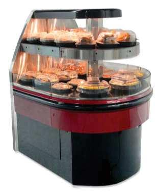


51
Controller for temperature control AK-CC 210
 User Guide Controller for temperature control AK-CC 210 ADAP-KOOL Refrigeration control systems Contents Introduction... 2 Operation... 3 Applications... 6 Survey of functions... 8 Operation...18 Menu
Controller for temperature control EKC 202D1
 User Guide Controller for temperature control EKC 202D1 ADAP-KOOL Refrigeration control systems Introduction Application The controller is used for temperature control refrigeration appliances in supermarkets
TY3, TY4 (ENTYCE) HOT/COLD ISLAND SELF-CONTAINED CASE INSTALLATION & OPERATION GUIDE
 HOT/COLD ISLAND SELF-CONTAINED CASE INSTALLATION & OPERATION GUIDE") /CHINO Installation & Operation Manual TY3, TY4 (ENTYCE) HOT/COLD ISLAND SELF-CONTAINED CASE INSTALLATION & OPERATION GUIDE Table of Contents Warning 3 General Information 4 Entyce Hot Cold Lifting Instructions
/CHINO Installation & Operation Manual TY3, TY4 (ENTYCE) HOT/COLD ISLAND SELF-CONTAINED CASE INSTALLATION & OPERATION GUIDE Table of Contents Warning 3 General Information 4 Entyce Hot Cold Lifting Instructions
Controller for appliance control AK-CC 450. Manual
 Controller for appliance control AK-CC 450 Manual Contents Introduction... 2 Operation... 4 Applications...12 Survey of functions...15 Operation...26 Menu survey...28 Connections...32 Data...34 Ordering...35
Controller for appliance control AK-CC 550A
 User Guide Controller for appliance control AK-CC 550A ADAP-KOOL Refrigeration control systems Introduction Application Complete refrigeration appliance control with great flexibility to adapt to all types
Controller for appliance control AK-CC 550B. Manual
 Controller for appliance control AK-CC 550B Manual Introduction Application Complete refrigeration appliance control with great flexibility to adapt to all types of refrigeration appliances and cold storage
Controller for appliance control AK-CC 550. Manual
 Controller for appliance control AK-CC 550 Manual Contents Introduction... 2 Operation... 4 Applications...12 Survey of functions...15 Operation...26 Menu survey...28 Connections...32 Data...34 Ordering...35
User Guide. Controller for appliance control AK-CC 450
 User Guide Controller for appliance control AK-CC 450 Contents Introduction... 2 Operation... 4 Applications...12 Survey of functions...15 Operation...26 Menu survey...28 Connections...32 Data...34 Ordering...35
Controller for temperature control - EKC 202A,B,C and EKC 302A,B
 Controller for temperature control - EKC 202A,B,C and EKC 302A,B Manual Introduction Application The controller is used for temperature control refrigeration appliances and cold room in supermarkets Control
SERIES NAV S Display Merchandisers
 SERIES NAV S Display Merchandisers Medium Temperature Merchandisers PLEASE READ THIS MANUAL BEFORE USING THE PRODUCT Installation & Operation Manual P/N 2400204D NAV S Series May 2006 HUSSMANN CORPORATION
/CHINO. Installation & Operation Manual ENTYCE ISLAND CASE SELF-CONTAINED REV INSTALLATION & OPERATION GUIDE SELF-CONTAINED ISLAND CASE ENTYCE
 ENTYCE ISLAND CASE SELF-CONTAINED /CHINO Installation & Operation Manual REV. 0317 ENTYCE ISLAND CASE SELF-CONTAINED INSTALLATION & OPERATION GUIDE Table of Contents General Informaon 5 Cut and Plan Views
UPRIGHT DELI CASE RGD
 /CHINO Installation & Operation RGD Manual REV. 0318 UPRIGHT DELI CASE RGD UPRIGHT DELI CASE INSTALLATION & OPERATION GUIDE 1. General Instructions /CHINO A publication of HUSSMANN Chino 13770 Ramona Avenue
SERIES NIM. Low Temperature Merchandisers PLEASE READ THIS MANUAL BEFORE USING THE PRODUCT
 SERIES NIM Low Temperature Merchandisers PLEASE READ THIS MANUAL BEFORE USING THE PRODUCT Hussmann Monterrey, Mexico Carretera Mexico-Laredo KM. 1009 Cienga de Flores, Nuevo Leon 65550 Mexico Phone: (52)
Glass Door Merchandiser Refrigerator and Freezer
 Glass Door Merchandiser Refrigerator and Freezer (Swing and Sliding Door ) Service, Installation and Care Manual Please read this manual completely before attempting to install or operate this equipment.
Solid Door Top Mount Reach-In Freezer
 Solid Door Top Mount Reach-In Freezer Service, Installation and Care Manual Please read this manual completely before attempting to install or operate this equipment. Notify carrier of damage! Inspect
Chef Base Refrigerators
 Chef Base Refrigerators Service, Installation and Care Manual Please read this manual completely before attempting to install or operate this equipment. Notify carrier of damage! Inspect all components
Sandwich/Salad Table Under-counter Refrigerator Worktop Refrigerator
 Sandwich/Salad Table Under-counter Refrigerator Worktop Refrigerator Service, Installation and Care Manual Please read this manual completely before attempting to install or operate this equipment. Notify
Installation. Manual. & Operation /CHINO. Roll in deli/dairy display Rev RID RID. Roll in deli/dairy display INSTALLATION & OPERATION GUIDE
 RID /CHINO Installation & Operation Manual Roll in deli/dairy display Rev. 0909 RID Roll in deli/dairy display P/N IGUP-RID-0909 INSTALLATION & OPERATION GUIDE Table of Contents General Instructions...2
Controller for controlling one evaporator EKC 414A1 REFRIGERATION AND AIR CONDITIONING. Manual
 Controller for controlling one evaporator EKC 414A1 REFRIGERATION AND AIR CONDITIONING Manual Introduction Application The controller is a complete control unit for refrigeration appliances with integrated
COUNTER TOP REFRIGERATION MODEL SERIES HUBM-2RB/HUBM-2FB/HUBM-3.5RB/HUBM-3.5FB HUBM-2R/HUBM-2F/HUBM-3.5R/HUBM-3.5F
 HUBM-2R HUBM-2F HUBM-3.5R HUBM-3.5F HUBM-2RB HUBM-2FB HUBM-3.5RB HUBM-3.5FB Please read this manual completely before attempting to install or operate this equipment. Notify carrier of damage! Inspect
UNDERCOUNTER REFRIGERATORS AND FREEZERS Installation, Operation and Maintenance Instructions
 UNDERCOUNTER REFRIGERATORS AND FREEZERS Installation, Operation and Maintenance Instructions Please read this manual completely prior to installing and operating this equipment. This manual describes how
SERVICE BAKERY CASE SUMMIT HIGH-VOLUME SGB
 /CHINO SGB SUIT HIGH-VOLUE SERVICE BAKERY CASE Installation & Operation anual REV. 0217 SGB SUIT HIGH-VOLUE SERVICE BAKERY CASE INSTALLATION & OPERATION GUIDE A publication of HUSSANN Chino 13770 Ramona
REFRIGERATED PREP TABLES Installation, Operation and Maintenance Instructions
 REFRIGERATED PREP TABLES Installation, Operation and Maintenance Instructions Please read this manual completely prior to installing and operating this equipment. This manual describes how to install,
Operation Manual and Parts Directory
 Operation Manual and Parts Directory Lettuce Crisper LC Glastender, Inc. 5400 North Michigan Road Saginaw, MI 48604-9780 800.748.0423 989.752.4275 Fax 800.838.0888 / 989.752.4444 www.glastender.com Rev.
Capacity controller EKC 331T REFRIGERATION AND AIR CONDITIONING. Manual
 Capacity controller EKC 331T REFRIGERATION AND AIR CONDITIONING Manual Introduction Application The controller is used for capacity regulation of compressors or condensers in small refrigerating systems.
/SPECIALTY DELI/BAKERY SERVICE MERCHANDISER Q4-DV U S E R M A N U A L - Q4-DV-8-R - Q4-DV-12-R
 /SPECIALTY 122017 Q4-DV DELI/BAKERY SERVICE MERCHANDISER U S E R M A N U A L Q4 - Q4-DV-4-R - Q4-DV-8-R - Q4-DV-12-R Table of Contents General Information 3 Case Sections 4 Installation 5 Receiving Case
Capacity controller for water chiller AK-CH 650
 Capacity controller for water chiller AK-CH 650 Menu operation via AKM Menu list This menu function can be used together with system software type AKM. The description is divided up into function groups
/CHINO. Installation & Operation Manual ISLAND PRODUCE REV DBP, DBRP 01, 03 INSTALLATION & OPERATION GUIDE DBP, DBRP 01, 03 ISLAND PRODUCE
 DBP, DBRP 01, 03 /CHINO Installation & Operation Manual ISLAND PRODUCE REV. 0917 DBP, DBRP 01, 03 ISLAND PRODUCE INSTALLATION & OPERATION GUIDE Table of Contents General Instructions...2 Cut and Plan Views...3
UNDERCOUNTER LABORATORY REFRIGERATORS and FREEZERS Installation, Operation and Maintenance Instructions
 UNDERCOUNTER LABORATORY REFRIGERATORS and FREEZERS Installation, Operation and Maintenance Instructions INSPECTION When the equipment is received, all items should be carefully checked against the bill
ConserveWell DROP-IN UNIT
 ConserveWell DROP-IN UNIT MODEL: CW-DI 87772 120V USA with Countdown Timer Thank You...for purchasing our ConserveWell Drop-In Heated Utensil Holder. This unit holds serving utensils above 140 F, keeping
MD Medium Temperature Self Contained Open Vertical Merchandisers
 MD Medium Temperature Self Contained Open Vertical Merchandisers MD-14 MD-10 IMPORTANT Keep in store for future reference! Installation & Service Manual P/N 2402646_D February 2012 P/N2402646D P/N 2402646_D
Duke Manufacturing Co.
 Installation and Operation Manual Front Line Merchandiser Model: FLM100 : Please read this manual completely before attempting to install, operate or service this equipment This manual is Copyright 2018
INSTALLATION and OPERATION INSTRUCTIONS
 INSTALLATION and OPERATION INSTRUCTIONS SINGLE DOOR freezer MODEL NOS. FN FS Finished Stainless Steel Top Non-Finished Top FS FN IMPORTANT INFORMATION This manual has been prepared to assist you in the
G-7s. Instruction Manual. G-Series Cooler COUNTERTOP COOLER. Part No.11IPA
 G-Series Cooler COUNTERTOP COOLER Part No.11IPA-061000 Instruction Manual FOR YOUR FUTURE REFERENCE This easy-to-use manual will guide you in getting the best use of your cooler. Remember to record the
INSTALLATION AND SERVICE MANUAL REMOTE TYPE DISPLAY CASE
 Multi-Deck Self Service Fresh Meat Merchandiser Multi-Deck Self Service Fresh Meat Merchandiser FPW-EXA085 FPW-EXA085 FPW-EXA025 FPW-EXA025 INSTALLATION AND SERVICE MANUAL REMOTE TYPE DISPLAY CASE TABLE
G-10s. Instruction Manual. G-Series Cooler UPRIGHT COOLER. Part No.11IPA
 G-Series Cooler UPRIGHT COOLER Part No.11IPA-062800 Instruction Manual FOR YOUR FUTURE REFERENCE Thank you for using our product. This manual will guide you in getting the best use of your cooler. Remember
E-Chef Hot Food Table Installation and Operation Manual
 E-Chef Hot Food Table Installation and Operation Manual Please read this manual completely before attempting to install or operate this equipment! Notify carrier of damage! Inspect all components immediately.
INSTALLATION AND OPERATING MANUAL
 INSTALLATION AND OPERATING MANUAL Salad Bars Olive Bars Food Prep Cases Refrigerated Cases with Air-Over Displays Refrigerated Cases with Coppered Cold Well Displays Cases with Under-Counter Refrigerators
INSTALLATION and OPERATING. INSTRUCTIONS for. SMZP26 Series. elf-contained Freezers
 S elf-contained Freezers INSTALLATION and OPERATING INSTRUCTIONS for Series ZERO ZONE Zero Zone, Inc. 110 N. Oakridge Dr. North Prairie, WI 53153-9792 1-800-247-4496 FAX: 1-414-392-6450 www.zero-zone.com
BOTTOM MOUNT REFRIGERATORS AND FREEZERS Installation, Operation and Maintenance Instructions
 BOTTOM MOUNT REFRIGERATORS AND FREEZERS Installation, Operation and Maintenance Instructions INSPECTION When the equipment is received, all items should be carefully checked against the Bill of Lading
Installation & Operation Manual
 Installation & Operation Manual Flat Top Bottle Cooler BC Series BC72 shown C US Form No. Z2295 Rev. 04.05.2018 JOB AREA ITEM NO. MODEL NO. BC24 SERIES BC36 SERIES BC48 SERIES BC24 shown BC72 shown BC48LT
RGDC RGDC /CHINO INSTALLATION & OPERATION GUIDE REFRIGERATED CURVED SELF-SERVICE MERCHANDISER REV REFRIGERATED CURVED SELF-SERVICE MERCHANDISER
 /CHINO RGDC REFRIGERATED CURVED SELF-SERVICE MERCHANDISER Installation & Operation Manual REV. 0318 RGDC REFRIGERATED CURVED SELF-SERVICE MERCHANDISER INSTALLATION & OPERATION GUIDE General Instructions
PLEASE READ THIS MANUAL BEFORE USING YOUR APPLIANCE. KEEP THIS MANUAL IN A SAFE PLACE FOR FUTURE REFERENCE.
 File name: ARDI Care & Use Manual.pub Last revised: Oct 10th 2008 PLEASE READ THIS MANUAL BEFORE USING YOUR APPLIANCE. KEEP THIS MANUAL IN A SAFE PLACE FOR FUTURE REFERENCE. ASSEMBLER / INSTALLER Leave
Operation Manual and Parts Directory
 Operation Manual and Parts Directory ST24, ST36, ST48, ST60, ST72 and ST96 Slide Top Coolers ST36-B ST48-SF Glastender, Inc. 5400 North Michigan Road Saginaw, MI 48604-9780 800.748.0423 989.752.4275 Fax
OWNER S MANUAL. Vintage Classic HEAT COOL models. Proudly Made in the USA
 OWNER S MANUAL Vintage Classic HEAT COOL models Proudly Made in the USA support@aquacomfort.com www.aquacomfort.com/service-and-support 888-475-7443 Manufacturing High Quality, High Efficiency Heat Pump
GCG-10. Instruction Manual. G-Series Cooler. Manual is for the following models: GCG-10-N33EB G-10-N33EB UPRIGHT COOLER
 G-Series Cooler GCG-10 UPRIGHT COOLER Manual is for the following models: GCG-10-N33EB G-10-N33EB Instruction Manual Manual is for the following models: GCG-10-N33EB G-10-N33EB Instruction Manual GCG-10
PLEASE READ THIS MANUAL BEFORE USING YOUR APPLIANCE. KEEP THIS MANUAL IN A SAFE PLACE FOR FUTURE REFERENCE.
 File name: ARFG-42FB Care & Use Manual.pub Last revised: June 3rd 2008 PLEASE READ THIS MANUAL BEFORE USING YOUR APPLIANCE. KEEP THIS MANUAL IN A SAFE PLACE FOR FUTURE REFERENCE. ASSEMBLER / INSTALLER
INSTALLATION AND OPERATION MANUAL
 INSTALLATION AND OPERATION MANUAL CTRH SERIES 460 Southport Commerce Blvd. Spartanburg SC 29306 Phone: 864-574-6004 Fax: 864-574-6005 CTRH-4 Congratulations! You have just purchased the finest commercial
User s Manual Warm N Cozy
 User s Manual Warm N Cozy Point A Technologies, Inc. 20957 Currier Road, Unit C, Walnut, CA 91789 U.S.A. TABLE OF CONTENTS Page 1. Safety Procedures and Precautions...3 2. Electrical Information......4
Technical Manual and Replacement Parts List. f Real Freezers
 Technical Manual and Replacement Parts List f Real Freezers MODELS: SKF27G/CFRL (SHOWN) SKF27GB/CFRL 1600 Xenium Lane North, Minneapolis, MN 55441-3787 Phone (763) 923-2441 1 Specifications Subject to
Installation & Operation Manual
 Installation & Operation Manual Glass Frosters FR Series FR48 SS shown C US Form No. Z2296 Rev. 01.16.2015 Glass Frosters Installation & Operation Manual JOB AREA ITEM NO. MODEL NO. FR24 SERIES FR36 SERIES
IM-04, IM-05 (ISLA) IM-H HOT MULTI- DECK DISPLAY
 IM-H HOT MULTI- DECK DISPLAY") /CHINO IM-04, IM-05 (ISLA) IM-H HOT MULTI-DECK DISPLAY Installation & Operation Manual REV. 0314 IM-04, IM-05 (ISLA) IM-H HOT MULTI- DECK DISPLAY INSTALLATION & OPERATION GUIDE A publication of HUSSMANN
/CHINO IM-04, IM-05 (ISLA) IM-H HOT MULTI-DECK DISPLAY Installation & Operation Manual REV. 0314 IM-04, IM-05 (ISLA) IM-H HOT MULTI- DECK DISPLAY INSTALLATION & OPERATION GUIDE A publication of HUSSMANN
Installation & Operations Manual Master-Bilt Products 908 Highway 15 North New Albany, MS Phone: (800)
") Installation & Operations Manual Master-Bilt Products 908 Highway 15 North New Albany, MS 38652 Phone: (800) 684-8988 PN 018-90000 Rev 01-09-12 TABLE OF CONTENTS INTRODUCTION..3 STORE CONDITIONS.3 WARNING
Installation & Operations Manual Master-Bilt Products 908 Highway 15 North New Albany, MS 38652 Phone: (800) 684-8988 PN 018-90000 Rev 01-09-12 TABLE OF CONTENTS INTRODUCTION..3 STORE CONDITIONS.3 WARNING
INSTRUCTIONS AK-CC 250A
 INSTRUCTIONS AK-CC 250A t amb = 0 - +55 C 230 V a.c. 50/60 Hz 2.5 VA 10 V < U < 256 V DO1. Refrigeration * DO2. Defrost * DO3. Fan or refrigeration 2 * Coordinated defrost CE (250 V a.c.) 8 (6) A 8 (6)
SHVSS SUMMIT HIGH-VOLUME SELF SERVICE BAKERY CASE SHVSS /CHINO INSTALLATION & OPERATION GUIDE REV SUMMIT HIGH-VOLUME SELF SERVICE BAKERY CASE
 SHVSS /CHINO Installation & Operation anual SUIT HIGH-VOLUE SELF SERVICE BAKERY CASE REV. 0317 SHVSS SUIT HIGH-VOLUE SELF SERVICE BAKERY CASE INSTALLATION & OPERATION GUIDE Table of Contents General Instructions...2
User Manual. Commercial School Milk Cooler User s Manual. Commercial School Milk Coolers: MC34, MC49, MC58
 Commercial School Milk Cooler User s Manual Commercial School Milk Coolers: MC34, MC49, MC58 12/2015 Please read the manual thoroughly prior to equipment set-up, operation and maintenance. - 1 - Exploded
Q2-SP Q2-SPN. DELI self SERVICE CASE DELI SELF SERVICE /CHINO INSTALLATION & OPERATION GUIDE P/N Q2-SPN DOE 2012 Energy Efficiency Compliant
 Installation & Operation Manual Rev. 1113 DOE 2012 Energy Efficiency Compliant Hussmann refrigerated merchandisers configured for sale for use in the United States meet or surpass the requirements of the
Instruction Manual. Window AC 12000BTU. Energy- Saving Mode. Wards.com MODEL: 12000BTU Item No.: V~, 60Hz, 1060W
 Energy- Saving Mode Window AC 12000BTU MODEL: 12000BTU 11.2 Montgomery Ward Customer Service 1112 7th Avenue, Monroe, WI 53566 8:00 am to Midnight, Monday through Friday Wards.com 1 888 557 3848 Instruction
Instruction Manual. Bottle Cooler. Models HBC-50 (-S) HBC-65 (-S) HBC-80 (-S) HBC-95 (-S) hoshizakiamerica.com. Issued: Revised:
 HBC-65 (-S) HBC-80 (-S) HBC-95 (-S) hoshizakiamerica.com. Issued: Revised:") Instruction Manual Bottle Cooler Models HBC-50 (-S) HBC-65 (-S) HBC-80 (-S) HBC-95 (-S) hoshizakiamerica.com Issued: 06-11-2018 Revised: WARNING Only qualified service technicians should install and service
Instruction Manual Bottle Cooler Models HBC-50 (-S) HBC-65 (-S) HBC-80 (-S) HBC-95 (-S) hoshizakiamerica.com Issued: 06-11-2018 Revised: WARNING Only qualified service technicians should install and service
BOTTOM MOUNT REFRIGERATORS & FREEZERS Installation, Operation and Maintenance Instructions
 BOTTOM MOUNT REFRIGERATORS & FREEZERS Installation, Operation and Maintenance Instructions INSPECTION When the equipment is received, all items should be carefully checked against the Bill of Lading to
AHPO-6/18 GOLD PROOFER OVEN
 AHPO-6/18 GOLD PROOFER OVEN For information or technical assistance, call: TOLL FREE 1(800) 735-DUKE (3853) or 1(314) 231-1130 PN 156081R 1 of 25 TABLE OF CONTENTS MANUFACTURER S INTRODUCTION...3 INSTALLATION...4
DELI SELF SERVICE Q3-SP
 /CHINO Q3-SP DELI SELF SERVICE CASE Installation & Operation anual REV. 0317 Q3-SP DELI SELF SERVICE CASE INSTALLATION & OPERATION GUIDE 1. General Instructions /CHINO A publication of HUSSANN Chino 13770
URS-1 SERVICE AND PARTS MANUAL SERIAL NUMBERS: UP TO
 URS-1 SERVICE AND PARTS MANUAL SERIAL NUMBERS: UP TO 06-10616. File name: URS-1 Service Manual up to 06-10616 Last revised: Jan. 30th 2009 TROUBLESHOOTING AND SERVICE GUIDE: The following is intended as
MR3CCUHV Temperature/Defrost Control
 Master Catalog 125 Temperature Controls Section A Product/Technical Bulletin Issue Date 0401 MR3CCUHV Temperature/Defrost Control The MR3CCUHV Temperature/Defrost Control is designed to control the temperature
Installation & Operations Manual for. BMG-HGP Model Bottom Mounted Full-Length Swing Glass Door Refrigerator Merchandisers. 4/17 Rev.
 Installation & Operations Manual for BMG-HGP Model Bottom Mounted Full-Length Swing Glass Door Refrigerator Merchandisers 4/17 Rev. D 57-02398 4/17 Rev. D 57-02398 2 TABLE OF CONTENTS INTRODUCTION.. 4
SCIENTIFIC WARMING CABINET Installation, Operation and Maintenance Instructions
 SCIENTIFIC WARMING CABINET Installation, Operation and Maintenance Instructions GENERAL 2 Inspection 2 Location 2 INSTALLATION 2 Door Alignment 2 Shelf Installation 2 Remote Contacts 3 2-10 Volt DC Output
MD Medium Temperature Self Contained Open Vertical Merchandisers
 MD Medium Temperature Self Contained Open Vertical Merchandisers MD-14 MD-10 Installation & Service Manual IMPORTANT Keep in store for future reference! MANUAL - I/O SELF CONTAINED MD P/N 2402646_E December
RCM-2. Instruction Manual. G-Series Cooler. Manual is for the following models: RCM-2-N13EB. **Patent Pending** RECHARGE COLD MERCHANDISER
 G-Series Cooler RECHARGE COLD MERCHANDISER 2 **Patent Pending** Manual is for the following models: -N13EB Instruction Manual FOR YOUR FUTURE REFERENCE This easy-to-use manual will guide you in getting
Manual is for the following models: G-26 GCG-26 GCG-26-C31N* G-26-C31N* GCG-26-C231N* GCG-26-CA31N* *G,I,M,7,J plug. Instruction Manual.
 G-Series Cooler G-26c/GCG-26c UPRIGHT COOLER Manual is for the following models: G-26 GCG-26 GCG-26-C31N* G-26-C31N* GCG-26-C231N* GCG-26-CA31N* *G,I,M,7,J plug Instruction Manual Manual is for the following
12,000 BTU Evaporative Portable Air Conditioner
 12,000 BTU Evaporative Portable Air Conditioner Owner s Manual Model # KY-32E Please read owner s manual carefully before operating the unit. TABLE OF CONTENTS PAGE Table of Contents. 2 Introduction....3
Insta-Therm Series Service, Installation and Operation Manual
 Insta-Therm 16000 Series Service, Installation and Operation Manual Please read this manual completely before attempting to install or operate this equipment! Notify carrier of damage! Inspect all components
Refrigerators. Technical Manual and Replacement Parts List FORM NO REV H MODEL SKTTR7FW MODEL SKC1220W
 Technical Manual and Replacement Parts List Refrigerators MODEL SKTTR7FW MODEL SKC1220W 1600 Xenium Lane North, Minneapolis, MN 55441-3787 Phone (763) 923-2441 FORM NO. 28963 REV H 1 Specifications Subject
/CHINO. Installation & Operation Manual TY3, TY4 (ENTYCE) REV ISLAND CASE INSTALLATION & OPERATION GUIDE ISLAND CASE TY3, TY4 (ENTYCE)
 REV ISLAND CASE INSTALLATION & OPERATION GUIDE ISLAND CASE TY3, TY4 (ENTYCE)") /CHINO TY3, TY4 (ENTYCE) Installation & Operation anual ISLAND CASE REV. 0218 TY3, TY4 (ENTYCE) ISLAND CASE INSTALLATION & OPERATION GUIDE Table of Contents Warning 4 General Informaon 5 Cut and Plan Views
/CHINO TY3, TY4 (ENTYCE) Installation & Operation anual ISLAND CASE REV. 0218 TY3, TY4 (ENTYCE) ISLAND CASE INSTALLATION & OPERATION GUIDE Table of Contents Warning 4 General Informaon 5 Cut and Plan Views
BLG-HGP Model Bottom Mounted Full-Length Swing Glass Door Freezer Merchandisers
 Installation & Operations Manual for BLG-HGP Model Bottom Mounted Full-Length Swing Glass Door Freezer Merchandisers 2 TABLE OF CONTENTS INTRODUCTION..... 4 STORE CONDITIONS........ 4 WARNING LABELS AND
Installation & Operations Manual for R-290 SERIES. BMG-HGP Model Bottom Mounted Full-Length Swing Glass Door Refrigerator Merchandisers 2/
 Installation & Operations Manual for R-290 SERIES BMG-HGP Model Bottom Mounted Full-Length Swing Glass Door Refrigerator Merchandisers 2/19 57-02650 2/19 57-02650 2 TABLE OF CONTENTS INTRODUCTION.. 4 STORE
OWNER S MANUAL. Models: AC110, AC125, AC150 made from 2003 through Proudly Made in the USA
 OWNER S MANUAL Models: AC110, AC125, AC150 made from 2003 through 2010 Proudly Made in the USA support@aquacomfort.com www.aquacomfort.com/service-and-support/ (888) 475-7443 Manufacturing High Quality,
HGM-1, 2 & 3 BS, TS. Bottom / Top Mount Medium Temperature Remote and Self Contained. Installation & Service Manual. Glass Door Merchandisers
 HGM-1, 2 & 3 BS, TS Bottom / Top Mount Medium Temperature Remote and Self Contained Glass Door Merchandisers HGM-3BS IMPORTANT Keep in store for future reference! HGM-2TS Installation & Service Manual
/SPECIALTY MEAT/FISH SERVICE MERCHANDISER U S E R M A N U A L. - Q3-M/F C-EP Case. Remote
 /SPECIALTY 092015 Q3 MEAT/FISH SERVICE MERCHANDISER U S E R M A N U A L Q3 - Q3-M/F S-EP Case - Q3-M/F C-EP Case Remote Table of Contents General Information 3 Case Sections 4 Installation 5 Unloading
INSTALLATION AND OPERATING MANUAL
 INSTALLATION AND OPERATING MANUAL Refrigerated Merchandisers with Air-Over Displays Refrigerated Low-Profile Mobile Merchandiser Refrigerated High-Profile Mobile Merchandiser Refrigerated Grab-N-Go Merchandiser
INSTALLATION and OPERATION INSTRUCTIONS
 INSTALLATION and OPERATION INSTRUCTIONS Single Door cooler series MODEL NOS. CS32SB CS32SG CS32SS CS32ST IMPORTANT INFORMATION To register your product, visit our web site at (www.perlick.com). Click on
Installation & Operations Manual. Master-Bilt Products 908 Highway 15 North New Albany, MS Phone: (800) /17 Rev.
 /17 Rev.") Installation & Operations Manual Master-Bilt Products 908 Highway 15 North New Albany, MS 38652 Phone: (800) 684-8988 4/17 Rev. D 57-02089 TABLE OF CONTENTS INTRODUCTION. 3 STORE CONDITIONS....... 3 WARNING
Installation & Operations Manual Master-Bilt Products 908 Highway 15 North New Albany, MS 38652 Phone: (800) 684-8988 4/17 Rev. D 57-02089 TABLE OF CONTENTS INTRODUCTION. 3 STORE CONDITIONS....... 3 WARNING
RCM-2. Instruction Manual. G-Series Cooler. Manual is for the following models: RCM-2-N13EB. **Patent Pending** RECHARGE COLD MERCHANDISER
 G-Series Cooler RCM-2 RECHARGE COLD MERCHANDISER 2 **Patent Pending** Manual is for the following models: RCM-2-N13EB Instruction Manual Manual is for the following models: RCM-2-N13EB Instruction Manual
Condensing Unit Installation and Operating Instructions
 Bulletin WCU_O&I 01 June 2003 Condensing Unit Installation and Operating Instructions WCU Air Cooled Condensing Unit Table of Contents Section 1. Section 2. Section 3. Section 4. Section 5. Section 6.
Operation Manual and Parts Directory
 Operation Manual and Parts Directory MF, MF6, MF8 Mug Frosters and Plate Chillers MF-S MF8-B Glastender, Inc. 00 North Michigan Road Saginaw, MI 860-9780 800.78.0 989.7.7 Fax 800.88.0888 / 989.7. www.glastender.com
REFRIGERATED DROP-INS (2-6)FT-DI Installation and Operating Manual
FT-DI Installation and Operating Manual") REFRIGERATED DROP-INS (2-6)FT-DI Installation and Operating Manual For service information call 800-544-3057 Please have the following information available before calling. Information can be found on
REFRIGERATED DROP-INS (2-6)FT-DI Installation and Operating Manual For service information call 800-544-3057 Please have the following information available before calling. Information can be found on
INSTALLATION and OPERATION INSTRUCTIONS
 INSTALLATION and OPERATION INSTRUCTIONS Glass Frosters MODEL NOS. FR24 Series FR36 Series FR48 Series FR60 Series c IMPORTANT INFORMATION This manual has been prepared to assist you in the installation
INSTALLATION AND OPERATING MANUAL
 INSTALLATION AND OPERATING MANUAL Refrigerated Cases with Air-Over Displays Refrigerated High Profile Grab-N-Go FOR PARTS & SERVICE Contact: Piper Products, Inc. Phone: (800) 544-3057 Ask for Service Department
BMG-HGP & BMG-SLP Model Bottom Mounted Full-Length Glass Door Refrigerator Merchandisers
 Installation & Operations Manual for BMG-HGP & BMG-SLP Model Bottom Mounted Full-Length Glass Door Refrigerator Merchandisers Sollatek controller Rev. 08-09-13 2 TABLE OF CONTENTS INTRODUCTION.. 4 STORE
DEHUMIDIFIER USER MANUAL 11 PINT FOR MODEL: 3PAD11 COMFORT...BUILT TO LAST
 COMFORT...BUILT TO LAST 11 PINT DEHUMIDIFIER USER MANUAL FOR MODEL: 3PAD11 Before using your dehumidifier, please read this manual carefully and keep it for future reference, along with your receipt. CONTENTS
GCG-26c. Instruction Manual. G-Series Cooler
 G-Series Cooler UPRIGHT COOLER Manual is for the following models: GCG-26-C14N7 GCG-26-C14NG GCG-26-C14NI GCG-26-C14NM GCG-26-C14NJ GCG-26 G-26-C14N7 G-26-C14NG G-26-C14NI G-26-C14NM G-26-C14NJ G-26 Instruction
OWNER S MANUAL. Vintage Signature Series models: AC750, AC1050, AC1100, AC1250, AC1500, AC1750. Proudly Made in the USA.
 OWNER S MANUAL Vintage Signature Series models: AC750, AC1050, AC1100, AC1250, AC1500, AC1750 Proudly Made in the USA support@aquacomfort.com 888-475-7443 Manufacturing High Quality, High Efficiency Heat
GSVM Medium Temperature Self Contained Open Vertical Merchandisers. Installation & Service Manual
 GSVM Medium Temperature Self Contained Open Vertical Merchandisers IMPORTANT Keep in store for future reference! Installation & Service Manual P/N 0515275_F July 2013 P/N 0515275_F iii IMPORTANT KEEP
ISF and ISM. Low and Medium Temperature Remote and Self Contained Island Merchandisers. Installation & Service Manual IMPORTANT
 ISF and ISM Low and Medium Temperature Remote and Self Contained Island Merchandisers IMPORTANT Keep in store for future reference! Installation & Service Manual P/N 0515154_B October 2010 P/N0515154B
INSTALLATION AND OPERATING MANUAL
 INSTALLATION AND OPERATING MANUAL Refrigerated Island Merchandiser FOR PARTS & SERVICE Contact: Piper Products, Inc. Phone: (800) 544-3057 Ask for Service Department IMPORTANT! This manual contains important
RCM-77. Instruction Manual. G-Series Cooler. U.S. Patent No. 8,215,125 RECHARGE COLD MERCHANDISER
 G-Series Cooler RECHARGE COLD MERCHANDISER U.S. Patent No. 8,215,125 Instruction Manual FOR YOUR FUTURE REFERENCE This easy-to-use manual will guide you in getting the best use of your cooler. Remember
Hoshizaki America, Inc.
 Hoshizaki America, Inc. Modular Crescent Cuber Models KM-1340MAH KM-1340MWH KM-1340MRH A Superior Degree of Reliability INSTRUCTION MANUAL www.hoshizaki.com Issued: 8-11-2005 IMPORTANT Only qualified service
Installation, Operation, and Maintenance Manual RTE14S & RTE14S-2. For the Taco Bell "Rethermalizer" Model Numbers
 Installation, Operation, and Maintenance Manual For the Taco Bell "Rethermalizer" Model Numbers RTE14S & RTE14S-2 NOTICES There are three different types of notices that you should be familiar with, a
UNDERCOUNTER LABORATORY FRONT BREATHING REFRIGERATORS AND FREEZERS Installation, Operation and Maintenance Instructions
 UNDERCOUNTER LABORATORY FRONT BREATHING REFRIGERATORS AND FREEZERS Installation, Operation and Maintenance Instructions Please read this manual completely prior to installing and operating this equipment.
Installation and Operations Manual for HORIZONTAL DISPLAY MERCHANDISERS
 Installation and Operations Manual for HORIZONTAL DISPLAY MERCHANDISERS 143539 Rev. A 07/11 TABLE OF CONTENTS INTRODUCTION 3 STORE CONDITIONS 3 WARNING LABELS AND SAFETY INSTRUCTIONS 4 PRE-INSTALLATION
Installation & Operations Manual. Master-Bilt Products 908 Highway 15 North New Albany, MS Phone: (800) REV: LN PN
 REV: LN PN") Installation & Operations Manual Master-Bilt Products 908 Highway 15 North New Albany, MS 38652 Phone: (800) 684-8988 REV: LN PN 297-90000 2 TABLE OF CONTENTS INTRODUCTION.. 4 STORE CONDITIONS..... 4 WARNING
Installation & Operations Manual Master-Bilt Products 908 Highway 15 North New Albany, MS 38652 Phone: (800) 684-8988 REV: LN PN 297-90000 2 TABLE OF CONTENTS INTRODUCTION.. 4 STORE CONDITIONS..... 4 WARNING