Featherweight Electric and V-Grid Water Heater Thermoplastic Tank Domestic Usage with Electronic Temperature Control
|
|
|
- Molly Thomas
- 5 years ago
- Views:
Transcription


1 Operation and Installation Manual Featherweight Electric and V-Grid Water Heater Thermoplastic Tank Domestic Usage with Electronic Temperature Control Limited Warranty and Tank Replacement
2 GENERAL INFORMATION PLEASE READ INSTRUCTIONS COMPLETELY BEFORE INSTALLING WATER HEATER IMPORTANT OWNER S RESPONSIBILITY Vaughn Thermal Corporation (herein called the Company) specifically does not expressly or impliedly warrant the merchantability or the fitness for any particular purpose or the performance of the heater within that system, nor does it assume liability for any consequential damage to general property or other components of the system. This appliance is designed to store water heated only by the electrical elements provided, at pressures of not more than 150 psi. Heat input from any external or additional source will void the warranty. The design anticipates the proper installation and care in use of the product. There is risk of property damage and personal injury inherent in the use of any hot water system. The Company cannot supervise the installation and therefore makes it a specific condition of the warranty that the customer will supervise the installation and use of this product to be sure they are performed in accordance with these instructions, as well as safe industry guidelines and proper local or national codes. Generalized instructions and procedures cannot anticipate all situations. For this reason, only qualified installers should perform the installation. A qualified installer is a licensed person who has appropriate training and a working knowledge of the applicable codes, regulations, tools, equipment and methods necessary for safe installation of an electrical resistance water heater. An installation checklist has been provided to help the customer ensure that all procedures for a safe installation have been followed. If questions regarding installation arise, check with your local plumbing and electrical inspectors for proper procedures and codes. Local codes take precedence over instructions in this manual. 1
3 INDEX GENERAL INFORMATION... 1 INDEX... 2 INSTALLATION GUIDELINES... 3 INSTALLATION CHECKLIST... 7 SERVICE INFORMATION... 9 MAINTENANCE WIRING DIAGRAM FIGURE FIGURE VAUGHN ELECTRONIC TEMPERATURE CONTROLLER OPERATION TROUBLESHOOTING PARTS LIST REPLACEMENT PARTS HOW TO OBTAIN SERVICE ASSISTANCE RESIDENTIAL USAGE ELECTRIC WATER HEATER TEN YEAR LIMITED TANK REPLACEMENT POLICY AND ONE YEAR LIMITED PARTS WARRANTY OPTIONAL LIFETIME WARRANTY REGISTRATION CARD To fully understand the purchaser s responsibilities for installing the water heater, please read the warranty. 26 Old Elm Street P.O. Box 5431 Salisbury, MA

4 INSTALLATION GUIDELINES A. INSPECTING AND PREPARING THE HEATER Remove the cardboard box, which comes packaged with the heater. It should contain the following: T&P valve, brass T, cold and hot piping with unions, insulation, and snap rivets. Do not cover or damage the temperature and pressure relief valve opening located in the topside of the tank (See FIGURE 1) B. LOCATION CAUTION: All tanks will eventually leak at some unpredictable time. Do not place the heater where there is a risk of property damage in the event of a leak. Place the heater on a solid foundation in a clean, dry location. The heater should be protected from freezing and water lines should be insulated to reduce energy and water waste. Leave sufficient room to service the electrical elements and controls. Do not install in an area where flammable liquids or combustible vapors are present. CAUTION: The heater s outer jacket is plastic and can melt. Do not install in close proximity to wood burning stove or other high temperature apparatus. NOTE: If heater is placed on blocks to raise it from the floor, be sure to support the entire bottom with at least ¾" plywood on the top of the blocks. 3
5 C. PROTECTION FROM WATER DAMAGE CAUTION: All water heaters have a risk of leakage at some unpredictable time. IT IS THE CUSTOMER S RESPONSIBILITY TO PROVIDE A CATCH PAN OR OTHER ADEQUATE MEANS, SO THAT THE RESULTANT FLOW OF WATER WILL NOT DAMAGE FURNISHINGS OR PROPERTY. The Warranty provided assures replacement within its terms, but specifically does not warrant against consequential damage caused by a leaking water heater. D. TEMPERATURE AND PRESSURE RELIEF VALVE WARNING: A POTENTIAL HAZARD TO LIFE AND PROPERTY MAY EXIST IN ANY WATER HEATER IF AN APPROVED TEMPERATURE-AND-PRESSURE RELIEF VALVE IS NOT PROPERLY INSTALLED. For protection against excessive pressures and temperatures in this water heater, install temperature-and-pressure protective equipment required by local codes, but not less than a combination temperature-and-pressure relief valve certified by a nationally recognized testing laboratory that maintains periodic inspection of production of listed equipment of materials, as meeting the requirements for Relief Valves and Automatic Gas Shutoff for Hot Water Supply Systems. ANSI Z This valve must be marked with a maximum set pressure not to exceed the marked maximum allowable working pressure of the water heater (150psi). Install the valve into an opening provided and marked for this purpose in the water heater, and orient it or provide tubing so that any discharge from the valve will exit only within 6 inches above, or at any distance below the structural floor and cannot contact any live electrical part. The discharge opening must not be blocked or reduced in size under any circumstances. CAUTION: A relief valve is designed to discharge excessively hot water. THE CUSTOMER IS RESPONSIBLE TO PROTECT PROPERTY AND PERSONNEL FROM HARM WHEN THE VALVE FUNCTIONS. Install the T&P provided on hot water outlet of tank as shown in FIGURE 1. Care must be taken to be sure that the stem of the pressureand-temperature relief valve is immersed in the water within the top 6 inches of the tank. The brass Tee fitting provided must be used on the hot outlet in combination with the T&P provided. NOTE: The top pan will not fit unless the Tee fitting AND elbow with straight pipe is used. 4
6 The drain line from the relief valve must not be concealed or blocked and must be protected from freezing. WARNING: IF THE WATER SUPPLY IS FROM A WELL, OR KNOWN TO HAVE HARD WATER, IT IS RECOMMENDED TO USE A PRESSURE RELIEF VALVE IN THE COLD WATER LINE AS WELL AS A T&P VALVE IN THE HOT WATER LINE. No valve of any kind should be installed between the relief valve and tank or in the drain line. E. WATER SUPPLY CONNECTIONS WARNING: Some local codes mandate the use of a backflow preventer or check valve or pressure-reducing valve. An adequate expansion tank (or other adequate means) must be installed to prevent pressure build up or damage from thermal expansion when a check valve or backflow preventer or pressure-reducing valve is used. Failure to do so could result in tank leakage and therefore void the warranty. All water supply fittings on this heater are brass do not over tighten or strip threads. Provide a shut off valve in the cold water line. Mark for future emergency use. It is recommended to use unions as per FIGURE 1. Do not apply heat directly to the cold-water inlet as it includes a plastic dip tube which will melt. Water connections are 3/4" male threaded fittings (Exception: They are 1.5" male on the P80FD and P120FD.) F. FILLING THE HEATER CAUTION: Do not put electrical power to the elements until after the heater is completely filled with water. Check that the temperature-and-pressure relief valve has been properly installed (mandatory requirement). Completely close the drain valve. Open the highest hot water faucet to allow air to escape from piping. Open the valve to the cold-water inlet and allow the heater and piping system to completely fill, as indicated by a steady flow of water from the open faucet. G. WIRING CONTROLS WARNING: The heater elements will be damaged instantly if energy is supplied before the tank is completely filled with water, thus voiding any warranty. A qualified electrician must provide a separate fused branch circuit, conforming to local or National Electric Codes. 5
7 Supply to the heater only the voltage stamped on the rating plate. Mark the electrical shut off clearly for future emergency use. Read wiring diagrams before making electrical connections (See WIRING DIAGRAM 1) Field connections with aluminum conductors must use connectors approved for copper to aluminum connection. CAUTION: There is a risk of electric shock in an ungrounded service. It is critical that this unit be wired with a power supply that has a service ground wire available. Be sure to connect the ground wire to the green ground screw in the junction box. H. SUPPLEMENTAL HEAT WARNINGS NOTE: Heat input from any external or additional source will void the warranty. When a supplemental heat source is connected to the Certified Household Electric Storage Tank Water Heater, provision must be made to limit the heat source temperature not to exceed that of the water heater thermostat setting. Caution: If the water heater has been retrofitted with supplemental heating equipment, you must adjust both the thermostat controlling the supplemental heat source (located in the water piping) and the temperature controller on the water heater to the same temperature. Failure to adjust both temperature controllers to the same setting can cause loss of proper temperature control. I. INSULATION INSTALLATION Place included fiberglass insulation between and around the water supply and element wires. Attach lid using snap rivets provided. Insulate hot water pipes with pipe insulation. 6
8 7 INSTALLATION CHECKLIST A. INSPECTING AND PREPARING THE HEATER Remove the cardboard box, which comes packaged with the heater. It should contain the following: T&P valve, brass T, cold and hot piping with unions, insulation, and snap rivets. Do not cover T&P relief valve opening. B. LOCATION Solid foundation and dry location. Protect heater water lines from freezing. Area free of flammable vapors. Sufficient room to service heater. Not in close proximity to wood burning stove. Where leak will not damage property. C. PROTECTION FROM WATER DAMAGE Be sure to make provisions to protect area from water damage if a leak should occur in the tank or connected fittings. D. TEMPERATURE AND PRESSURE RELIEF VALVE Warning: Improper installation will present potential hazard to life and property. A T&P Relief Valve with an 8-inch stem should be used. Check to be sure that proper relief valve requirements are met. Brass Tee fitting and T&P installed 3/4" discharge pipe properly protected from freezing and restrictions. No valve between tank and relief valve or in drain line. Provision for hot water discharge from relief valve. E. WATER SUPPLY CONNECTIONS (See FIGURE 1) Do not over tighten brass threads. Mark the water shutoff for future reference. Do not apply heat to cold inlet. If there is a check valve (sometimes in water meter), backflow preventer or pressure-reducing valve, install an adequate size expansion tank. F. FILLING THE HEATER Completely fill heater before turning on elements. Water connections completed and free of leaks. Check for proper installation of relief valve. Close drain valve.
9 Open highest hot water faucet. Open cold water inlet valve and fill system. G. WIRING TANK MUST BE FULL OF WATER BEFORE POWER IS ON. Separate fused branch circuit (refer to local codes). Mark the electrical shut off for future reference. Wiring diagram (See WIRING DIAGRAM 1) Aluminum conductors. Check to see that voltage on rating plate and supply agree. CAUTION: Unit must be properly grounded. H. INSTALLATION COMPLETED AND CHECKLIST FILLED OUT BY: DATE: SPECIAL NOTE: Test of hot water after installation is necessary to be sure temperature controls are working properly. (See WATER TEMPERATURE REGULATION) 8

10 SERVICE INFORMATION WATER TEMPERATURE REGULATION WARNING: Exposure to 125 F or hotter water can cause scalding injuries. Appropriate caution must be taken when using hot water. Special supervision must be given to those who cannot act quickly such as children, invalids or elderly persons. The temperature of the water in the heater is regulated by a Vaughn Electronic Temperature Controller with temperature sensors located behind the jacket and insulation. These automatic controls are set at the factory to maintain a water temperature of 120 F. Although these controls are designed to industry standards, they can fail to control temperature properly without any notice, and therefore should be tested periodically for your protection. The test is very simple: Turn on the hot water faucet and measure the maximum temperature with an accurate thermometer. If the temperature is above the safe limits for your circumstances call a service technician to adjust or replace the control. DANGER: IF YOU DISCOVER EXTREME HOT WATER COMING FROM THE FAUCET, IMMEDIATELY SHUT OFF THE ELECTRICITY AT THE MAIN SWITCH AND CALL COMPETENT SERVICE PERSONNEL. ANY OVERHEATED WATER HEATER IS A POTENTIAL HAZARD TO LIFE AND PROPERTY. DO NOT OPERATE UNTIL THE SOURCE OF THE PROBLEM HAS BEEN DETERMINED AND ELIMINATED. Water temperature over 125 F can cause severe burns instantly or death from scalds. Children, disabled and elderly are at the highest risk of being scalded. See instruction manual before setting temperature at the water heater. Feel water before bathing or showering. Properly maintained, your water heater can provide years of dependable, trouble free service. It is 9
11 suggested that the purchaser use the following preventive maintenance program. A. SAFETY CONTROL The heater has a high-limit control that is located on the top of the tank. This surface mounted high-limit is designed to interrupt the flow of electricity to all elements when it senses dangerously high temperatures. If this switch operates, do not attempt to reset. A dangerous situation is indicated and a qualified service man should be called to find the source before the unit is operated again. Temperature of the water should be tested periodically at the faucet to be sure temperature controllers are working properly. B. TEMPERATURE CONTROL To change the temperature set point for hot water output, from the home screen, press the AND buttons on the controller. The display will flash the new temperature set point as the or buttons are pressed. Once the desired temperature setting has been reached, allow the screen to time out after about 5 seconds. The new setpoint can also be saved by pressing the AND buttons. Pressing will cancel the changes without saving. The display will now show the newly set temperature (e.g., 116 ). See VAUGHN ELECTRONIC TEMPERATURE CONTROLLER OPERATION for more information. C. OPTIONAL V-GRID CONTROL SPECIFIC UTILITY PROGRAMS ONLY Unlocking the Bottom Element Using V-Grid Activation Unit o The V-Grid Activation Unit connects to the Electronic Temperature Control (ETC) and detects the activation status. In other words, it detects whether the device is locked or unlocked. Simply pushing the button on the AU will change the activation status, so the status will go from locked to unlocked or from unlocked to locked. Connecting the V-Grid Activation Unit o The V-Grid Activation Unit connection is made by inserting the USB style connector into the USB style 10


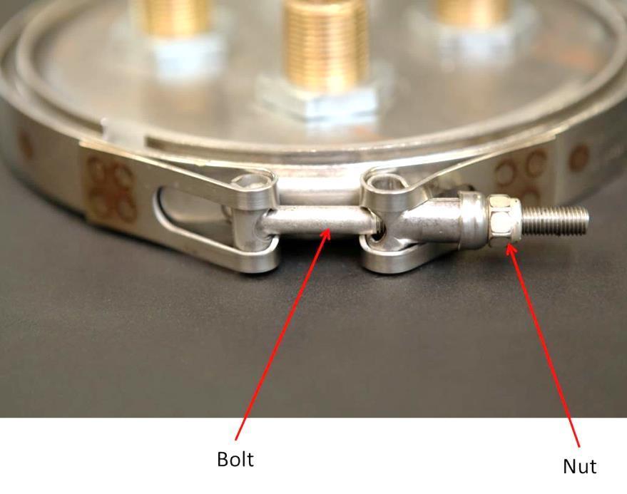
12 port on the left side of the electronic controller. These are not USB compatible connections. The V- Grid AU can be powered from the included DC power supply with output rated 12V, 0.5 Amps. The power supply is not required when connected to a control that has power. V-Grid Activation Status Indicator o Red Device locked o Green Device Unlocked o Blinking Red Not connected, trying to connect. o Blinking Green Status change is in progress. WIFI Status Indicator o Red LED on, not blinking: Power is on. o Green LED on, not blinking: The device is linked to the factory servers. o Green LED blinking once per second: The device is communicating with the factory servers. D. INSTALLING THE REMOVABLE ELEMENT ASSEMBLY 11 Element Assembly is installed at the factory. The following is provided for servicing or removing the Element Assembly. Insert Element Assembly with plastic O-ring housing and align top fittings so the Top Element (Red Wires) faces forward. WARNING: Plastic O-ring housing must be properly installed. (See FIGURE 2) Failure to do this will void the warranty. Install and secure the clamp and nut in the following manner: o Place the clamp around the flange and coil plate.
13 o o o Ensure the bolt is facing forward and slide through hole. Hold the clamp together with one hand and tighten nut with the other hand. (See FIGURE 2) Tighten to 15 ft.-lbs. NOTE: Be sure that clamp is installed level. WARNING: Plastic O-ring housing must be installed properly (See FIGURE 2) to prevent leaking. Failure to do this will void the warranty. Must use new O-rings if replaced or removed. 12
14 MAINTENANCE Properly maintained, your water heater can provide years of dependable, trouble free service. It is suggested that the purchaser follow the preventive maintenance program outlined below. A. CONTROLS A periodic inspection of the operating controls, heating elements and wiring should be made by qualified service personnel. Temperature of the water should be tested periodically at the faucet to be sure thermostats are working properly. B. LONG TERM SHUT DOWN If the water heater is to remain idle for an extended period of time, the power and water to the heater should be turned off to conserve energy. The water heater and piping should be drained, if they might be subjected to freezing temperatures. After a long shutdown period, qualified service personnel should check the heater s operations and controls. Make certain the water heater is filled before placing it in operation. C. DRAINING THE HEATER CAUTION: Shut off all power to the heater before draining water. To drain the tank, a hot water faucet must be opened to admit air to the tank. 1. Attach a hose to the drain valve on the heater. 2. Close valve on the cold water line to the heater. 3. Open the drain valve and direct the water to a drain. D. EMERGENCY Should the heater be subject to flood, fire, or other damaging conditions, turn off the power and water to the heater. DO NOT place water heater in operation again until it has been thoroughly checked by qualified service personnel. 13
15 WIRING DIAGRAM 1 14

16 15 FIGURE 1

17 FIGURE 2 16


18 VAUGHN ELECTRONIC TEMPERATURE CONTROLLER OPERATION A. ABOUT THE CONTROLLER The Vaughn Electronic Temperature Controller provides the user with the ability to control and customize the operation of their water heater. The 4-digit display shows the current status of the water heater, and can display useful information such as current temperature conditions inside the tank, error notifications, and more. It allows basic customization, such as mode and temperature set point, as well as more advanced options, such as temperature differential, and display options. Once the setup is complete the water heater is automatic in operation and will maintain a full tank of water at the temperature setting of the controller. B. POWERING UP YOUR WATER HEATER FOR THE FIRST TIME When the unit is first powered up, the default home screen is shown. This screen shows the temperature set point (e.g., 120). C. THE HOME SCREEN The home screen provides a quick reference to the current status of the water heater, showing either the setpoint temperature or the actual temperatures at the top and bottom of the tank, denoted by t and b preceding the temperatures. The temperature readouts can be displayed in Fahrenheit or Celsius. There are power indicators to show which if any element should be on. These indicators blink when the element is heating properly. 17

19 D. BUTTON OVERLAY The button overlay provides the user with a means to alter the configuration settings and control the operation of the water heater. A brief description of the basic functionality of each button is provided below. Detailed descriptions of how to use these buttons to perform certain functions is provided throughout this manual. Power: Used for putting the water heater into standby E. VACATION OVERRIDE mode, will be displayed. Used in the options menu to navigate backwards. Used to cancel setpoint selection without saving. Mode: Used for navigating the options menu. Serves as a cancel button in certain menus. Up: Used for increasing numeric settings. Also scrolls up when changing options. Can be held for auto scroll. Down: Used for decreasing numeric settings. Also scrolls down when changing options. Can be held for auto scroll. Away: Used for entering / exiting vacation override. Also used to set / unset child lock. Vacation mode deactivates the water heater for extended periods of time by overriding the current mode the water heater is set to. This is useful for saving energy when the water heater will not be used for a period of several days. The unit will maintain a water temperature of 50 F to prevent freezing. To activate vacation override, press the button on the controller. The display will show A-07, indicating the default vacation length of 7 days. The minimum vacation length is 2 days and the maximum is 99 days. Use the or buttons to adjust the desired length of time to use vacation mode. The water heater will exit vacation mode automatically one day before the specified time period has elapsed. It is 18
20 designed this way such that when the user returns from being away, hot water will be available. Once the desired time period is displayed, press the button to save the selection. The water heater will now be in Vacation mode. The display will show A-##, where ## is the number of days remaining in the vacation mode period. To manually cancel or end Vacation mode, press the button once. F. CHILD LOCK Child Lock is essentially a button locking mechanism. If the user wishes, he or she may set the child lock, which will disrupt any future attempt to change modes, change the set point, etc. The user will be locked out of performing any function on the device until the child lock is released. To activate the Child Lock feature, press and hold the button until chld is displayed on the screen. The controller is now locked. To deactivate the child lock, press and hold the button until un is displayed. You will be returned to the home screen. G. TEMPERATURE SETPOINT 19 The temperature setpoint represents the desired approximate temperature of the water inside the heater. The setpoint may be adjusted to your liking. There are pre-defined temperature limits to prevent extremely hot or freezing water in the unit and surrounding piping. To change the temperature set point for hot water output, from the home screen, press the AND buttons on the controller. The display will flash the new temperature set point as the or buttons are pressed. Once the desired
.")
21 temperature setting has been reached, allow the screen to time out after about 5 seconds. The new setpoint can also be saved by pressing the AND buttons. Pressing will cancel the changes without saving. The display will now show the newly set temperature (e.g., 116 ). To access the options menu, from the home screen, press and hold the button until the display reads dift (top differential), this is the first selection in the options menu. To navigate the options menu, continue to press the button to cycle through the available options until the desired option is displayed. When the option to be changed is displayed, press the or buttons to enter the edit mode. When the display is flashing, the option may be altered by pressing the or buttons until the desired choice is displayed. To set the change, press the button, or press the button. The change will be made and the controller will return the user to the options menu. To exit the menu at any time, let the display timeout after 5 seconds or press the button. 20


22 H. DIAGNOSTICS Enabling this option causes the control to perform various checks, including making sure each element works correctly. Any errors will be displayed after all of the tests are complete. The software version is displayed before normal operation resumes: 21
23 I. TOP DIFFERENTIAL AND BOTTOM DIFFERENTIAL J. BUZZER A temperature differential represents how far the water temperature can fall before the water heater must call for heat again. For example, if the setpoint is 120 F and the differential is 10 F, then after satisfying at 120 F, the water temperature must fall to 110 F before the water heater will call for heat. The buzzer is programmed to sound every 30 seconds whenever an error has been detected. It is highly recommended that the user leave this buzzer on. However, this option allows the user to turn the buzzer off if desired. To turn the buzzer on or off, in the edit mode press the or buttons to alternate between On and OFF. K. DISPLAY The display setting provides the ability to select whether the home shows the setpoint temperature (diss) or the measured water temperature (dist) inside the tank for the upper and lower sections. If dist is selected, the home screen will cycle the display to show the top temperature (designated by a t preceding the measurement) for 5 seconds, followed by the bottom temperature (designated by a b preceding the measurement) for 5 seconds. L. DEFAULTS Enabling this option will reconfigure the controller to factory defaults. The factory defaults are shown below. o Temperature Setpoint: 120 F o Top Differential: 30 o Bottom Differential: 10 o Buzzer: On o Display: Show Set Point o Degrees: Fahrenheit o Disable Errors: All enabled 22
24 M. DEGREES To set the unit back to factory defaults, in the edit mode press the or buttons to alternate between cancelling the operation, no, or resetting to default, YES. The degrees option provides the user with the ability to switch between standard and metric temperature readings. The degf choice will set the temperatures to be displayed in Fahrenheit, and the degc choice will set the temperatures to be displayed in Celsius. To change the display units, in the edit mode press the or buttons to alternate between degrees Fahrenheit, degf, or degrees Celsius, degc. To set the change, let the display timeout after 5 seconds, press the the button. N. DISABLE ERRORS button, or press The disable errors option allows for the use of external timer controllers to inhibit operation of the elements during certain times without removing power to the controller or otherwise affecting operation. The top and bottom element errors can be chosen individually to be turned on or off. If no external control is used, these errors should remain enabled. 23
25 TROUBLESHOOTING FOR QUALIFIED SERVICE PERSONNEL ONLY ERROR CODES When the Vaughn Electronic Temperature Controller detects an abnormal condition, the display will alternate between the home screen, ERR, and then the error code below. ETC-H2O ERROR CODE POSSIBLE CAUSE POSSIBLE SERVICE REQ D 1. Temperature Sensor Issue (Top or Bottom sensor) 2. Controller Sensing Issue F-01 (Top sensor) 1. Temperature Sensor Issue F-02 (Bottom sensor) 2. Controller Sensing Issue *Check wire connections *Replace or repair probes 1. Top Element Malfunction *Check wire connections F-03 (Top Element) *replace or repair probes F-04 (Bottom Element) 2. Controller Output Issue *Replace top element *Replace or repair control 1. Bottom element malfunction *Check wire connections 2. Controller output issue *Replace top element *Replace or repair control F-05 (Both Elements) 1. High limit tripped *Check high limit 2. Controller output issue *Replace or repair control NATURE OF TROUBLE POSSIBLE CAUSE POSSIBLE SERVICE REQ D 1. Water Heater Switch turned off. Turn ON 2. Improper Wiring *Check wiring diagram 3. No Power blown fuse No Hot Water a. Circuit over load *Check wiring diagram b. Improper wiring *Provide adequate circuit 4. Manual reset limit open a. Controller malfunction Adjust setting or replace* b. Heat-up due to loose wires *Tighten connections 1. Heater undersized *Install proper size heater Not enough Hot Water Water too hot or too cool 2. Element malfunction *Replace element 3. Controller malfunction *Restore default settings 1. Control setting too high or low Change setting as required 2. Control out of calibration Adjust setting or replace* 3. Insulation around elements *Replace insulation properly not properly replaced CAUTION: For your safety, DO NOT attempt repair of electrical wiring, thermostat(s), heating elements or other operating controls. Refer repairs to qualified service personnel. 24
26 PARTS LIST T&P Relief Valve Located above and to the left of hot water outlet. High Limit Safety Switch Manual reset switch designed to shut off all electrical circuits if water reaches the high limit setpoint. Electronic Control For constant temperature control, temperature controls are specifically designed for Featherweight water heaters. Temperature sensors are located under the plastic jacket and may be located using the template provided in the replacement kit. Water Diffuser Dip Tube Introduces cold water at the bottom of the tank in a flat, gentle swirl, preventing turbulent mixing with heated water above. Hot Water Outlet Nipple Located on the top of the heater for easy installation and access. Wiring & Connections Located on the top of the heater for easy installation and access. Long-Life Heating Elements Waste is reduced with immersed heating elements because all available heat passes directly into the water. Low watt density elements assure longer life and reduce mineral buildup. Clamp Stainless steel removable v-clamp for servicing heater. Drain Easy access to drain the tank located at the bottom of the heater. Plastic Jacket Durable & easy-to-clean jacket high-density plastic. High-Density Insulation Three inches of high-density foam blanket the storage tank which significantly reduces heat loss. NOTE: When ordering parts, please specify model and serial number of tank, shown on the rating plate, as well as parts name, information and number. See following page(s). 25
27 REPLACEMENT PARTS 26
28 HOW TO OBTAIN SERVICE ASSISTANCE Vaughn Thermal Corporation does not have a service department or personnel to service your heater in the field. A qualified installer or service technician must do all service work. Therefore, if you have any questions about your new water heater concerning service adjustment, repair, routine maintenance, or replacement - first contact your installer, plumbing contractor or service agency. In the event that the contractor, for whatever reason, is unable to help, refer to the telephone directory commercial listings for qualified service assistance. If neither action has solved your problem, please have your plumbing contractor contact us for assistance. CUSTOMER RELATIONS DEPARTMENT General@vaughncorp.com VAUGHN THERMAL CORPORATION 26 OLD ELM STREET P.O BOX 5431 SALISBURY, MA When contacting Vaughn the following information should be made available: A. Model and serial number of the water heater as listed on inside back cover of this manual or on the rating plate on the heater. B. Address where water heater is installed. C. Name and address of dealer from whom the heater was purchased and installer s name and address. D. Date of original installation and any service work performed since then. E. Details of the problem as you can best describe. F. List of people who have been contacted regarding the problem. 27
29 RESIDENTIAL USAGE ELECTRIC WATER HEATER TEN YEAR LIMITED TANK REPLACEMENT POLICY AND ONE YEAR LIMITED PARTS WARRANTY Vaughn Thermal Corporation, (hereinafter called the company) offers the following Limited Warranty and Tank Replacement Policy to the purchaser/owner of this thermoplastic residential water heater. This Limited Warranty and Tank Replacement Policy is not transferable beyond the original purchaser/owner and is not valid if tank is removed from initial installation site. The Company reserves the right to require proof of purchase as a condition of this warranty. Excludes any implied warranty of merchantability or fitness for any particular purpose. LIMITED WARRANTY DURATION: The warranty is effective for (1) year beginning with the date of original purchase. At the time the claim is filed, if the original purchaser cannot provide an original sales receipt, deed or equivalent document in the case of a new home purchase, this warranty shall begin from the date of manufacture as indicated by the serial number. COVERAGE: The warranty covers any component part of the thermoplastic residential water heater proven to be defective in workmanship or material. Recovery under the terms of this agreement is subject to prior approval by the company. COMPANY OBLIGATION: Repair or replacement is at the option of the company and constitutes the fulfillment of ALL obligations of the Company hereunder. LIMITATION: All repairs or replacements will be made F.O.B. the company. The purchaser must pay for transportation, service, labor, installation, administrative fees or other costs involving the repair or replacement of such component parts. YOUR ACTION: When you discover a defect, immediately notify the dealer from whom the heater was purchased. If you cannot locate the dealer, contact the Company. TANK REPLACEMENT POLICY DURATION: (10) years from the date of original purchase. Exception: (5) years for commercial use, see Limitations below. If the original purchaser cannot provide an original sales receipt, deed or equivalent document in the case of a new home purchase, this warranty shall begin from the date of manufacture as indicated by the serial number. COVERAGE: Replacement policy covers only the storage tank for leaks caused by the corrosive effects of the water under normal and proper use. Recovery under the terms of this agreement is subject to prior approval by the company. The tank replacement policy excludes any performance warranty implied or specific of merchantability and fitness for its intended use. COMPANY OBLIGATION: Repair of the original tank or replacement of the entire heater with a new comparable model is at the option of the Company and constitutes the fulfillment of all the obligations of the Company hereunder. In replacing or repairing the thermoplastic residential water heater, the Company reserves the right to make such changes in details of design, construction or material as shall in their judgment constitute an improvement of former practices. REPLACEMENT: When a replacement is made under the terms of this policy, the replacement unit will have a policy of replacement only for the remaining time under the original policy. The Company reserves the right to require return of the defective unit at the expense of the purchaser. LIMITATION: The duration of the tank replacement policy on the tank assembly shall be reduced to a period of five years if (1) the purchaser is a business, partnership or corporation, or if (2) the water heater is used for a commercial, institutional, industrial, non-residential or multi-unit. All repairs or replacements will be made F.O.B. the Company. The purchaser must pay for transportation, service, labor installation, administrative fees or other costs involving the repair or replacement of such part. YOUR ACTION: When you discover a defect, immediately notify the dealer from whom the heater was purchased. If you cannot locate the dealer, contact the Company EXCLUSIONS AND LIMITATIONS Limited Warranty and Tank Replacement Policy are valid only if you comply with the following conditions and limitations: 1. The water heater must be correctly installed according to the installation manual provided with the unit and all applicable local and national codes. 2. The unit must be operated within the factory calibrated temperature limits and water pressure not exceeding 150 psi. 3. Any failure or malfunction that results from improper or negligent operation, accident, abuse (including freezing), misuse, unauthorized alteration or improper maintenance is specifically excluded. 4. Any failure or malfunction that results from failure to keep the tank full of potable water, free to circulate at all times, and free of damaging water sediment or scale deposits, is specifically excluded. In areas where adverse water conditions are suspected (i.e. calcium and other minerals), it is essential that the water be tested and appropriate action be taken to prevent damage to the water heater. 5. This Limited Warranty and Tank Replacement Policy specifically exclude any implied warranty of merchantability or of fitness for any particular purpose, as well as any performance warranty. IN NO EVENT SHALL THE COMPANY BE LIABLE FOR ANY INCIDENTAL OR CONSEQUENTIAL DAMAGES WHATSOEVER. Some states do not allow the exclusion or limitation of implied warranties or of liability for incidental or consequential damages, so the above limitation(s) or exclusion(s) may not apply to you. 28
30 The following information should be noted At time of installation and retained for future reference. Model No. Serial No. Date Installed Dealer s Name Address City State Zip 26 Old Elm Street P.O. Box 5431 Salisbury, MA Revision
31 OPTIONAL LIFETIME WARRANTY REGISTRATION CARD DATE Available to Residential, Single Family Homes Only Yes, I wish to purchase the Optional Lifetime Warranty! PURCHASER S NAME HOME ADDRESS CITY STATE ZIP HOME PHONE TANK (9 DIGIT) SERIAL NUMBER COMPANY PURCHASED FROM INSTALLING COMPANY NAME ADDRESS CITY STATE ZIP COMPANY PHONE DATE OF INSTALLATION Optional Lifetime Warranty on newly purchased tanks (Not available on replacement tanks), may be purchased by completing and returning this form to Vaughn Thermal Corporation along with a payment of $199 within 30 days of installation / occupancy. Optional Ten Year Extended Warranty (Replacement tanks only): If the original tank is replaced under warranty with a new tank, you can get an additional ten year warranty added to your current warranty period for a cost of $199. For example if you currently only have 4 years left on your warranty for $199 this would become 14 years. Send this completed form in with INITIAL HERE: METHOD OF PAYMENT: CHECK PAYABLE TO: VAUGHN THERMAL CORP. ENCLOSED. CHARGE MY: VISA MASTERCARD ACCOUNT NUMBER V number (V number is last three digits of number printed on back of credit card.) EXP. DATE SIGNATURE Complete form, cut along dotted line, and return with payment to: VAUGHN THERMAL CORPORATION P.O. BOX 5431 SALISBURY, MA
Hydrastone Lined Electric Water Heater
 Hydrastone Lined Electric Water Heater (Commercial Usage with Electronic Temperature Control) Operation and Installation Manual (LIMITED WARRANTY AND TANK REPLACEMENT POLICY) The following information
Peerless Partner PV Series Indirect Fired Water Heater
 Operation and Installation Manual Peerless Partner PV Series Indirect Fired Water Heater Limited Warranty and Tank Replacement GENERAL INFORMATION PLEASE READ INSTRUCTIONS CAREFULLY BEFORE INSTALLING WATER
Alliance SL Indirect - Fired Water Heater
 INSTALLATION, OPERATING AND SERVICE INSTRUCTIONS FOR Alliance SL Indirect - Fired Water Heater Including Warranty Information For service or repairs to the water heater, call your heating contractor. When
INSTALLATION, OPERATION AND MAINTENANCE MANUAL FOR COMPACT POINT-OF-USE ELECTRIC WATER HEATER
 INSTALLATION, OPERATION AND MAINTENANCE MANUAL FOR COMPACT POINT-OF-USE ELECTRIC WATER HEATER BASE MODEL CE110 2015 Edition HUBBELL ELECTRIC HEATER COMPANY P.O.BOX 288 STRATFORD, CT 06615 PHONE: (203)
Use & Care Manual. Electric Tankless Water Heaters. With Installation Instructions for the Installer AP15447 (10/10)
") Use & Care Manual With Installation Instructions for the Installer Electric Tankless Water Heaters The purpose of this manual is twofold: one, to provide the installer with the basic directions and recommendations
Use & Care Manual With Installation Instructions for the Installer Electric Tankless Water Heaters The purpose of this manual is twofold: one, to provide the installer with the basic directions and recommendations
INSTALLATION AND OPERATING INSTRUCTIONS
 17 West Street West Hatfield, MA 01088 Phone: (413) 247-3380 * (800) 582-8423 Fax: (413) 247-3369 E-mail: info@stiebel-eltron-usa.com SB 150, SB 200 Glass Lined Indirectly Fired Water Heaters With Single
Electric Mini Tank Water Heaters ME10 ME25 ME40 ME60
 Electric Mini Tank Water Heaters ME10 ME25 ME40 ME60 Installation and Operating Instruction Manual V01.2018 Table of Contents Important Safety Instructions 3 General Information 3/6 Technical Data 4-5
ERGOMAX 7 INSTALLATION
 ERGOMAX 7 INSTALLATION INSTALLATION MUST CONFORM TO LOCAL CODES 1. WITH HYDRONIC BOILERS All ERGOMAX 7 units must be installed vertically. Adjustable feet for levelling are provided. PRESSURE RELIEF VALVE:
SEISCO SUPERCHARGER EXTENDER/BOOSTER INSTALLATION GUIDE & OWNERS MANUAL
 SEISCO SUPERCHARGER EXTENDER/BOOSTER INSTALLATION GUIDE & OWNERS MANUAL This manual is provided as a guide to installation. All installations must comply with any and all local and national electrical
Installation Instructions
 P700U -21NHP Base Non -Programmable Thermostats Installation Instructions Designed and Assembled in the USA. US patents: US20060165149 A1, USD578026 SI, US6205041 B1 A14005 Base Non---Programmable Thermostat
Spa Control System OWNER S MANUAL
 LIMITED WARRANTY ONE YEAR LIMITED WARRANTY: UNITED SPAS, INC. warrants, to the original purchaser, the Spa Equipment against defects in materials or workmanship for a period of one year from date of purchase.
OPERATING AND INSTALLATION MANUAL
 OPERATING AND INSTALLATION MANUAL TANKLESS ELECTRIC WATER HEATER WITH ELECTRO-MECHANICAL FLOW SWITCH» MINI 2» MINI 2.5» MINI 3» MINI 3.5» MINI 4» MINI 6 The Mini series is tested and certified by WQA against
Mini Tank water heater Electric undersink Water heaters GL GL 4 - GL 6+
 Mini Tank water heater Electric undersink Water heaters GL 2.5 - GL 4 - GL 6+ IMPORTANT SAFETY INSTRUCTIONS WARNING When using electrical appliances, safety precautions to reduce the risk of fire, electric
Water Heaters. Use & Care Manual. Electric Residential. With Installation Instructions for the Installer. Double Element Residential Electric Models
 Use & Care Manual With Installation Instructions for the Installer Electric Residential Water Heaters Double Element Residential Electric Models The purpose of this manual is twofold: one, to provide the
Installation Manual WARNING. Add-on Controller Installation Kit NPE-180A/210A/240A
 Installation Manual Add-on Controller Installation Kit NPE-180A/210A/240A This device is designed to work with NPE-180A/210A/240A water heaters ONLY. WARNING All Installations should be done only by a
Thermostat Series. Installation Manual TSTBM-RRS--TW-A Revised 02-13
 Installation Manual Thermostat Series TSTBM-RRS--TW-A Remote Temperature Sensor (Requires TSTBM3H2CPH6W-A) TSTBM-RRS--TW-A 2 TSTBM-RRS--TW-A Table Of Contents Table of Contents Thermostat Quick Reference...
OPERATING AND INSTALLATION MANUAL
 OPERATING AND INSTALLATION MANUAL TANKLESS ELECTRIC WATER HEATER WITH ELECTRO-MECHANICAL FLOW SWITCH» MINI 2» MINI 2.5» MINI 3» MINI 3.5» MINI 4» MINI 6 The Mini series is tested and certified by WQA against
Installation Manual NPE-180A/240A WARNING. Add-on Controller Installation Kit
 Installation Manual Add-on Controller Installation Kit NPE-180A/240A This device is designed to work with NPE-180A/240A models ONLY. WARNING All Installations should be done only by a qualified expert
GEOTHERMAL STORAGE TANKS
 GEOTHERMAL STORAGE TANKS INSTALLATION OPERATION MAINTENANCE Instruction Manual The storage tank is sold as a component part. It has been factory equipped with a booster element, and thermostat with high
ELECTRIC WATER HEATER INSTALLATION & OPERATING INSTRUCTION MANUAL
 ELECTRIC WATER HEATER INSTALLATION & OPERATING INSTRUCTION MANUAL THE MANUFACTURER OF THIS HEATER WILL NOT BE LIABLE FOR ANY DAMAGE RESULTING FROM FAILURE TO COMPLY WITH THESE INSTRUCTIONS. READ THESE
TORRID MARINE YACHT QUALITY Since Owner s Manual
 Marine Water Heaters Owner s Manual Plumbing Configuration Note: While Torrid Marine is always happy to offer advice, we highly recommend you choose a professional marine technician to install your new
 http://waterheatertimer.org/how-to-install-under-counter-water-heater.html 1 IMPORTANT SAFETY INSTRUCTIONS Warning When using electrical appliances, basic safety precautions to reduce the risk of fire,
WKS 4000 SERIES (USA only) --INSTALLATION INSTRUCTIONS--
 --INSTALLATION INSTRUCTIONS--") 8610 Production Avenue San Diego, California 92121 (858) 566-7465 Fax (858) 566-1943 WKS 4000 SERIES (USA only) --INSTALLATION INSTRUCTIONS-- Thank you for choosing a BREEZAIRE cooling unit. We believe
8610 Production Avenue San Diego, California 92121 (858) 566-7465 Fax (858) 566-1943 WKS 4000 SERIES (USA only) --INSTALLATION INSTRUCTIONS-- Thank you for choosing a BREEZAIRE cooling unit. We believe
Solar Indirect Water Heater
 To the Installer: Please attach these instructions next to the water heater. To the Consumer: Please read these and all component instructions and keep for future reference. Solar Indirect Water Heater
Storage Tanks. Instruction Manual. To the Installer: Please attach these instructions next to the water heater.
 To the Installer: Please attach these instructions next to the water heater. To the Consumer: Please read these and all component instructions and keep for future reference. Storage Tanks Instruction Manual
Flow Factor ~
 Flow Factor ~ 216-765-4231 The DHC-E series is tested and certified by WQA against NSF/ANSI 372 for lead free compliance. STIEBEL ELTRON Inc. 17 West Street West Hatfield MA 01088 Tel. 413-247-3380 Fax
ECCOTEMP. Point of Use Tankless Water Heaters EP-2.4 / EP-7.0. Installation and Operating Instruction Manual. Shop Online.
 ECCOTEMP Point of Use Tankless Water Heaters EP-2.4 / EP-7.0 Installation and Operating Instruction Manual Product Support Eccotemp.com/help-desk Shop Online Eccotemp.com/products Store Locator Eccotemp.com/locator
SOLARHOT. SuperVox. Description / Applications System Overview. Installation/ Owner s Manual
 SOLARHOT SuperVox Installation/ Owner s Manual Description / Applications System Overview The SOLARHOT SuperVox solar thermal glycol system. The SuperVox allows for easy installation of large solar water
OWNER S MANUAL PLEASE READ AND SAVE THESE INSTRUCTIONS WHOLE ROOM RADIATOR HEATER. Model: HO-0221 THERMOSTAT
 145x210mm 单黑 君 2017.5.4 OWNER S MANUAL THERMOSTAT WHOLE ROOM RADIATOR HEATER Model: HO-0221 PLEASE READ AND SAVE THESE INSTRUCTIONS 1 IMPORTANT INSTRUCTIONS WARNING! When using electrical appliances, basic
OPERATING AND MAINTENANCE MANUAL FOR ELECTRIC STAINLESS STEEL HEATER FOR DEIONIZED (DI) WATER ELECTRIC HEATER COMPANY BASE MODEL D
 WATER ELECTRIC HEATER COMPANY BASE MODEL D") OPERATING AND MAINTENANCE MANUAL FOR ELECTRIC STAINLESS STEEL HEATER FOR DEIONIZED (DI) WATER ELECTRIC HEATER COMPANY BASE MODEL D HUBBELL ELECTRIC HEATER COMPANY P.O. BOX 288 STRATFORD, CT 06615 PHONE:
OPERATING AND MAINTENANCE MANUAL FOR ELECTRIC STAINLESS STEEL HEATER FOR DEIONIZED (DI) WATER ELECTRIC HEATER COMPANY BASE MODEL D HUBBELL ELECTRIC HEATER COMPANY P.O. BOX 288 STRATFORD, CT 06615 PHONE:
5) Do not start or stop the unit by inserting or pulling out the power plug.
 Do not start or stop the unit by inserting or pulling out the power plug.") 3058080 V170306 PURCHASE INFORMATION Thank you for choosing a Soleus Air Portable Air Conditioner. This Owner s Manual will provide you with valuable information necessary for the proper care and maintenance
3058080 V170306 PURCHASE INFORMATION Thank you for choosing a Soleus Air Portable Air Conditioner. This Owner s Manual will provide you with valuable information necessary for the proper care and maintenance
OPERATING INSTRUCTIONS
 OPERATING INSTRUCTIONS SPECIALTY REFRIGERATED TRANSPORT CABINETS FOR SATELLITE LOCATIONS RBQ-96 Caution: Read the instructions before using the machine. CONGRATULATIONS......and thank you for purchasing
Owner s Guide. 24-inch Gas Wall Oven with Time-Of-Day Clock and Timer Canada w A/01/08
 Owner s Guide 24-inch Gas Wall Oven with Time-Of-Day Clock and Timer TABLE OF CONTENTS IMPORTANT SAFETY INSTRUCTIONS... 2-4 MAINTENANCE... 11... Oven or broiler door... 11 CLOCK AND TIMER... 5 Oven bottom...
INSTALLATION, OPERATION AND MAINTENANCE MANUAL FOR COMMERCIAL INDIRECT POWERED WATER HEATER
 INSTALLATION, OPERATION AND MAINTENANCE MANUAL FOR COMMERCIAL INDIRECT POWERED WATER HEATER ELECTRIC HEATER COMPANY BASE MODEL T Edition 0 HUBBELL ELECTRIC HEATER COMPANY P.O. BOX 88 STRATFORD, CT 0665
Installation and Operation Guide
 Hot Water on Demand Installation and Operation Guide Thermostatic Series 18kW, 21kW, 24kW 118 º F www.atmorusa.com Table of Contents Description Page Safety Guidelines...2 Technical Information...3 Plumbing...
INSTALLATION AND OPERATION INSTRUCTIONS
 MODEL: RCT-MLT III INSTALLATION AND OPERATION INSTRUCTIONS INTRODUCTION IF YOU CANNOT READ OR UNDERSTAND THESE INSTALLATION INSTRUCTIONS DO NOT ATTEMPT TO INSTALL OR OPERATE This remote control system
Installation and Operation Guide
 Hot Water on Demand Installation and Operation Guide Thermo-Pro Thermostatic Series 18kW, 21kW, 24kW, 27kW 118 º F www.atmorusa.com Table of Contents Description Page Safety Guidelines...2 Technical Information...3
Seaward Products OWNER S MANUAL WATER HEATERS. Serial Number:
 Seaward Products WATER HEATERS OWNER S MANUAL Serial Number: IMPORTANT SAFETY INSTRUCTIONS WARNING When using electrical appliances, basic safety precautions to reduce the risk of fire, electrical shock,
INSTALLATION INSTRUCTIONS
 INSTALLATION INSTRUCTIONS FOR AQUECOIL HYDRONIC HEATING UNITS GENERAL INFORMATION The AQUECOIL Hydronic Heating Unit is offered in many different capacities and physical configurations in order to match
ALL WEATHER SL-SERIES QUARTZ TUBE ELECTRIC INFRARED RADIANT HEATER INSTALLATION USE & CARE MANUAL
 ALL WEATHER SL-SERIES QUARTZ TUBE ELECTRIC INFRARED RADIANT HEATER TABLE OF CONTENTS: INSTALLATION USE & CARE MANUAL IMPORTANT INFORMATION Assembly Instructions 2 Wiring Instructions 2 Outdoor Installation
26 LB CAPACITY ICE MAKER
 26 LB CAPACITY ICE MAKER INSTRUCTION MANUAL CATALOG NUMBER BIMY126S Thank you for choosing BLACK+DECKER! PLEASE READ BEFORE RETURNING THIS PRODUCT FOR ANY REASON. If you have a question or experience a
Power Pack Service Manual
 Power Pack Service Manual MMPP4301-EP MMPP4301 MMPP4301-WC MMPP4301-PKG MMPP4301-PKG-WC MMPP4302 MMPP4302-WC MMPP4302-PKG MMPP4302-PKG-WC MMPP4303-PKG MMPP4303-PKG-WC MMPP4303-PKG-3 MMPP4305-PKG MMPP4305-PKG-WC
Portable Air Conditioner 6,000 BTU 8,000 BTU 10,000 BTU
 Portable Air Conditioner 6,000 BTU 8,000 BTU 10,000 BTU OPERATING INSTRUCTIONS PCR-06-01 PCR-08-01 PCR-10-01 3058080 V170223 PURCHASE INFORMATION Thank you for choosing a Chigo Portable Air Conditioner.
Sun Bandit Hybrid Water Heater Installation and Operation Solar Hybrid Energy Systems Patent(s) Pending
 Pending") Solar Hybrid Energy Systems Patent(s) Pending Sun Bandit Hybrid Water Heater Installation and Operation Solar Hybrid Energy Systems Patent(s) Pending Instruction Manual Solar Hybrid Energy Systems Patent(s)
Solar Hybrid Energy Systems Patent(s) Pending Sun Bandit Hybrid Water Heater Installation and Operation Solar Hybrid Energy Systems Patent(s) Pending Instruction Manual Solar Hybrid Energy Systems Patent(s)
Point-of-Use Water Heater Owner s Manual. Installation, Care & Use
 Point-of-Use Water Heater Owner s Manual Installation, Care & Use W152 T & P VALVE (PRE-INSTALLED ON SOME MODELS) HOT WATER OUTLET (½" NPT FEMALE) COLD WATER INLET VALVE (NOT SUPPLIED) ON-OFF SWITCH COLD
INSTALLATION & SERVICE MANUAL
 INSTALLATION & SERVICE MANUAL ELECTRIC WATER HEATER THE WARRANTY ON THIS WATER HEATER IS IN EFFECT ONLY WHEN THE WATER HEATER IS INSTALLED AND OPERATED IN ACCORDANCE WITH LOCAL CODES AND THESE INSTRUCTIONS.
ELECTRIC FIREPLACE OWNER S MANUAL
 ELECTRIC FIREPLACE OWNER S MANUAL MODELS EL1346C 4001358 WARNING: If the information in this manual is not followed exactly, a fire or electrical shock may result causing property damage, personal injury
SAVE THESE INSTRUCTIONS
 Important Safety Instructions When using this electrical equipment, basic safety precautions should always be followed, including the following: 1. READ AND FOLLOW ALL INSTRUCTIONS. 2. This appliance must
READ MANUAL BEFORE OPERATING SYSTEM Read the owner s manual thoroughly before operating to ensure the most efficient use of the system.
 READ MANUAL BEFORE OPERATING SYSTEM Read the owner s manual thoroughly before operating to ensure the most efficient use of the system. Attention Installer: Please be sure this manual and warranty information
VENSTAR T1070 FAN COIL THERMOSTAT PROGRAMMABLE 2 OR 4 PIPE SYSTEMS OWNER S MANUAL AND INSTALLATION INSTRUCTIONS
 VENSTAR FAN COIL THERMOSTAT FAN COIL THERMOSTAT T1070 NON- PROGRAMMABLE 2 OR 4 PIPE SYSTEMS Remote sensor ready 3 speed fan control Self-prompting adjustment Auto 2-pipe changeover when used with ACC-SENFC
HEAT STORM PORTABLE QUARTZ INFRARED HEATER USER MANUAL TABLE OF CONTENTS
 HEAT STORM PORTABLE QUARTZ INFRARED HEATER USER MANUAL TABLE OF CONTENTS Safety Awareness.....3 Installations & Instructions........6 Operations & Controls..........7 Troubleshooting Guide...11 Questions
User s Manual and Warranty Information for Counterweighted Chain Drive ThyssenKrupp Access
 II User s Manual and Warranty Information for Counterweighted Chain Drive ThyssenKrupp Access Part #2139703 Rev. G II Table of Contents Introduction...3 Elevator Overview...4 Description of Features...5-7
Solar Storage Tank with Electric Backup Instruction Manual
 To the Installer: Please attach these instructions next to the water heater. To the Consumer: Please read these and all component instructions and keep for future reference. Solar Storage Tank with Electric
RESIDENTIAL STORAGE TANK OWNER S MANUAL INSTALLATION AND OPERATING INSTRUCTIONS
 RESIDENTIAL STORAGE TANK OWNER S MANUAL INSTALLATION AND OPERATING INSTRUCTIONS If the information in these instructions is not followed exactly, a fire or explosion may result causing property damage,
Operating Instructions READ AND SAVE THESE INSTRUCTIONS
 Operating Instructions READ AND SAVE THESE INSTRUCTIONS Aprilaire Communicating Thermostat Model 8870 CAUTION: Do not set to OFF mode during periods when freezing temperatures could occur. Thank you for
INSTALLATION AND SERVICE MANUAL
 INSTALLATION AND SERVICE MANUAL Electric Power Water Heater 12kW 162kW NOTE: retain this manual for future reference Installation and service must be performed by Qualified Service Personnel Only. WARRANTY:
Solar Indirect Water Heater
 To the Installer: Please attach these instructions next to the water heater. To the Consumer: Please read these and all component instructions and keep for future reference. Solar Indirect Water Heater
VT SERIES VERTICAL TOASTER OPERATOR S MANUAL TABLE OF CONTENTS
 VT SERIES VERTICAL TOASTER OPERATOR S MANUAL This equipment chapter is to be inserted in the Equipment Manual MANUFACTURED EXCLUSIVELY FOR McDONALD S BY FRYMASTER, L.L.C. P.O. BOX 51000 SHREVEPORT, LOUISIANA
INSTALLATION & TESTING MANUAL
 INSTALLATION & TESTING MANUAL ***CAUTION: Do not lift by yellow enclosure. Reference installation instructions for proper lifting and moving techniques. IMPROPER INSTALLATION MAY RESULT IN RISK OF SCALDING
Installation Instructions / Warranty
 Installation Instructions / Warranty Massaud 18112001 Massaud 18115001 Axor Massaud 3-Hole Lavatory Mixer Trim with Short Spout 18112001 Axor Massaud 3-Hole Lavatory Mixer Trim with Long Spout 18115001
PORTABLE AIR CONDITIONER OWNER S MANUAL
 PORTABLE AIR CONDITIONER OWNER S MANUAL ASSEMBLY AND OPERATING INSTRUCTIONS MODELS: JHS-A018-10KR SKU#: 130004 JHS-A018-12KRH SKU#: 130005 WARNING: Read and follow all warnings and instructions in this
5+2 DAY. OWNER S MANUAL Venstar Inc. 05/08
 Digital Thermostat residential THERMOSTAT 5+2 DAY PROGRAMMABLE up to 1-heat & 1-cool PUMP Stages: 1-Heat, 1-Cool Battery or System Powered Back-Lit Digital Display Fahrenheit or Celsius Service Filter
Owner s Manual. Digital. Heat Pump. 5+2 Day Programmable. Model S1-THEH21P5S HVAC SERVICE PARTS TM
 Owner s Manual Model S1-THEH21P5S HVAC SERVICE PARTS TM Heat Pump 5+2 Programmable Digital T h e rm ostats t a t BACKLIT DISPLAY Use with most Heat Pump systems: 1-Heat, 1-Cool 2-Heat, 1-Cool Control up
Power Pack Service Manual
 Power Pack Service Manual MMPP4301-EP MMPP4301 MMPP4301-PKG MMPP4302 MMPP4302-PKG MMPP4305-PKG MMPP4301-WC MMPP4302-WC MMPP4305-PKG-WC www.micromatic.com 1 TABLE OF CONTENTS Equipment Specifications...
Owner s Manual. Model 8800 Universal Communicating Thermostat. Includes Operating Instructions and Warranty Information
 Model 8800 Universal Communicating Thermostat Owner s Manual Includes Operating Instructions and Warranty Information READ AND SAVE THESE INSTRUCTIONS 61000762A 8800 Tstat Owners.indd 1 3/28/11 4:19:57
Owner s Manual. Digital Thermostat. Heat/Cool & Heat Pump 7-Day Programmable S1-THEM22P7S COMMERCIAL. Model HVAC SERVICE PARTS
 Owner s Manual Model COMMERCIAL TM BACKLIT DISPLAY HVAC SERVICE PARTS Heat/Cool & Heat Pump 7-Day Programmable Digital Thermostat Use with most Heat Pump Systems: 2-Heat, 2-Cool Stages: 2-Heat, 2-Cool
Controlled Energy Corp. 340 Mad River Park Waitsfield, VT TOLL FREE
 Controlled Energy Corp. 340 Mad River Park Waitsfield, VT 05673 TOLL FREE 866-330-2729 www.controlledenergy.com/tech Important Safety Instructions When using this electrical equipment, basic safety precautions
User s Manual and Warranty Information ThyssenKrupp Access
 User s Manual and Warranty Information ThyssenKrupp Access Welcome to your Destiny ThyssenKrupp Access would like to thank you for choosing the Destiny. You have purchased one of the finest residential
Water Heaters. Manufactured under trademark license by: Rheem Manufacturing Company P.O. Box , Montgomery, AL
 Use & Care Manual With Installation Instructions for the Installer Electric Residential Water Heaters Single and Double Element Models, Residential 20 120 Gallon Model: HE Series, GE Series, PE Series,
User Manual. Juice Extractor MODEL: WJE2BSLA
 User Manual Juice Extractor MODEL: WJE2BSLA 1. READ these instructions carefully before installing and operating the appliance. Keep them for further reference. 2. Record in the space below the SERIAL/MODEL
FLCH4R Garage and Utility Electric Heater
 FLCH4R Garage and Utility Electric Heater Installation, Operation & Maintenance Instructions Model No. Volts Amps Watts BTU/HR Phase High Low High Low High Low Min Fuse Size* FLCH4R 208 17.3 8.66 3600
Industrial Vacuums, Inc
 Instructions/Spare Parts Manual Nilfisk Model GWD255 Drum Top Vacuum CAUTION: This Nilfisk vacuum cleaner is not to be used in explosion-hazardous areas, as serious injury could result. Under no circumstances
COMMERCIAL ELECTRIC WATER HEATER OWNER S MANUAL OPERATION AND MAINTENANCE INSTRUCTIONS
 COMMERCIAL ELECTRIC WATER HEATER OWNER S MANUAL OPERATION AND MAINTENANCE INSTRUCTIONS Make sure to follow the instructions mentioned in this manual in order AVERTISSEMENT to reduce the risk of fire, explosion,
 Changing the Light Bulb The light bulb is located behind the Temperature control. IMPORTANT: Depending on your model, the light bulb in your new refrigerator may use LED technology. If your model uses
Laing Thermotech. Autocirc The Instant Hot Water Pump Models E1-BCANCT1W-06 and E1-BCANRT1W. Installation & Operating Manual
 Installation & Operating Manual Please read this manual carefully before attempting to install, operate or maintain the product described. Failure to comply with the information provided in this manual
TMC. Installation and Operation Manual TMC. Temperature and Pressure Monitoring for Heating and Cooling Applications. Temperature Monitoring Control
 Installation and Operation Manual Temperature and Pressure Monitoring for Heating and Cooling Applications Temperature Monitoring Control VALVE OPEN ALARM System= 128 o F Alarm At= 130 o F RESET /BACK
Model No. CZ2011O Oak Finish CZ2011C Cherry Finish CZ2011W Walnut Finish CZ2011B Black Finish DIGITAL QUARTZ INFRARED HEATER OWNER S MANUAL
 Model No. CZ2011O Oak Finish CZ2011C Cherry Finish CZ2011W Walnut Finish CZ2011B Black Finish DIGITAL QUARTZ INFRARED HEATER OWNER S MANUAL PLEASE SAVE THESE INSTRUCTIONS WARNING: READ THIS OWNER S MANUAL
VENSTAR T1075 FAN COIL THERMOSTAT 7 DAY PROGRAMMABLE 2 OR 4 PIPE SYSTEMS OWNER S MANUAL AND INSTALLATION INSTRUCTIONS
 VENSTAR FAN COIL THERMOSTAT FAN COIL THERMOSTAT T1075 7 DAY PROGRAMMABLE 2 OR 4 PIPE SYSTEMS 3 Occupied, 1 Unoccupied Override capable 3 speed fan control Auto 2-pipe changeover when used with accessory
VX SERIES Wireless Thermostat with Occupancy Sensor
 VX SERIES Wireless Thermostat with Occupancy Sensor INSTRUCTION MANUAL Table of Contents Thermostat Installation... 7 Installing the Wireless Control Card...8 Mounting the thermostat to the wall...9 Thermostat
INSTALLATION & OPERATING INSTRUCTIONS MODEL #17900 KEGERATOR MANUAL
 INSTALLATION & OPERATING INSTRUCTIONS MODEL #17900 KEGERATOR MANUAL TABLE OF CONTENTS PAGE # SAFETY INSTRUCTIONS......... 2 INSTALLATION INSTRUCTIONS................... 3 CABINET LOCATION GUIDELINES...
Installation & Operating Instructions
 Installation & Operating Instructions indirect water heaters TO THE INSTALLER: This manual is the property of the owner and must be affixed near the water heater for future reference. TO THE OWNER: This
H 2. Hot Water Storage/ Booster Tanks INSTALLATION, OPERATION & MAINTENANCE MANUAL MODELS OST30 OST40 OST60 OST60L OST80 OST80C OST115 OST115C
 MODELS OST30 OST40 OST60 OST60L OST80 OST80C OST115 OST115C O Hot Water Storage/ Booster Tanks For Single Tank Installations INSTALLATION, OPERATION & MAINTENANCE MANUAL 30, 40, 60, 80, 115 Gallon L =
PORTABLE AIR CONDITIONER OWNER S MANUAL
 PORTABLE AIR CONDITIONER OWNER S MANUAL ASSEMBLY AND OPERATING INSTRUCTIONS MODELS: JHS-A018-10KR SKU#: 130004 JHS-A018-12KRH SKU#: 130005 JHS-A018-14KRH SKU#: 130009 WARNING: Read and follow all warnings
OPERATING INSTRUCTIONS
 OPERATING INSTRUCTIONS ORIGINAL INSTRUCTIONS MOBILE HUMI-TEMP CABINETS "ETC-1826-HD" SERIES: Non-Insulated 18"x26" Tray Server "ETC-UA-HD" SERIES: Non-Insulated Universal Server P SERIES: Banquet Servers
INSTALLATION AND MAINTENANCE GUIDE TRENDY 1000 T ELECTRONIC LAVATORY FAUCET
 INSTALLATION AND MAINTENANCE GUIDE TRENDY 1000 T ELECTRONIC LAVATORY FAUCET 1 INDEX 1 TECHNICAL DATA 2 TEMPERATURE ALTERNATIVES 3 PACK CONTENTS 4 PRE-INSTALLATION INFO 5-6 FAUCET INSTALLATION 7 ADJUSTING
SPA BLOWER OWNER'S MANUAL XXXX, XXXX, XXXX, XXXX, XXXX, XXXX fax
 SPA BLOWER OWNER'S MANUAL 80015-XXXX, 80016-XXXX, 80017-XXXX, 80018-XXXX, 80019-XXXX, 80020-XXXX fax 888.610.3839 2015 323300-015 6/15 THIS PAGE INTENTIONALLY LEFT BLANK. 2 Operating Instructions and Parts
Installation Instructions / Warranty. Massaud
 Installation Instructions / Warranty Massaud 18450001 Axor Massaud Free-Standing Tub Filler 18450001 Technical Information Max. incoming water pressure 145 psi Recommended water pressure 14.5-72 psi Max.
Portable Induction Ranges
 9130, 9130-C 9131-1 9132-1 Portable Induction Ranges INSTALLATION AND OPERATING INSTRUCTIONS IMPORTANT INFORMATION READ BEFORE USE It is recommended that maintenance and repairs be conducted by authorized
TWO GALLON ELECTRIC WATER HEATER INSTALLATION & OPERATING INSTRUCTION MANUAL
 TWO GALLON ELECTRIC WATER HEATER A Spanish language version of these instructions is available by contacting the manufacturer listed on the rating plate. La version Espanola de estas instrucctions se puede
OPERATION, SERVICE & PARTS MANUAL
 OPERATION, SERVICE & PARTS MANUAL BROASTER 620NXP & 621 EASY BREADER Be sure ALL installers read, understand, and have access to this manual at all times. MODEL 620NXP MODEL 621 Genuine Broaster Chicken,
Installation Instructions PP-AS20 Anti-Scale System
 Installation Instructions PP-AS20 Anti-Scale System THIS UNIT MUST BE INSTALLED BY A LICENSED PLUMBER TO VALIDATE THE WARRANTY. COMPONENTS PP-AS20 Filter Housing PP-AS20R Filter Cartridge Installation
POWER PACK SERVICE MANUAL
 POWER PACK SERVICE MANUAL MMPP4301-EP MMPP4301 MMPP4301-WC MMPP4301-PKG MMPP4301-PKG-WC MMPP4302 MMPP4302-WC MMPP4302-PKG MMPP4302-PKG-WC MMPP4303-PKG MMPP4303-PKG-WC MMPP4303-PKG-3 MMPP4305-PKG MMPP4305-PKG-WC
SuperStor Ultra Stainless Steel Storage Tank
 SuperStor Ultra Stainless Steel Storage Tank INSTALLATION START-UP MAINTENANCE PARTS Storage Tank Models SSU-30CB / SSU-45CB SSU-60CB / SSU-80CB / SSU-119CB For Residential and Commercial Use This manual
INSTRUCTION MANUAL P Heating and 1 Cooling
 REPLACEMENT COMPONENTS DIVISION CARRIER CORPORATION www.totaltouch.info Technical Support: 1-866-90TOUCH (1-866-908-6824) INSTRUCTION MANUAL P286-1200 2 Heating and 1 Cooling Physical Dimensions Case:
BLOWER ACCESSORY MODEL #FIB100 Español p. 17
 ITEM #0293810 BLOWER ACCESSORY MODEL #FIB100 Español p. 17 Questions, problems, missing parts? Before returning to your retailer, call our customer service department at 1-877-886-5989, 8:00 a.m - 4:30
INSTALLATION OPERATION MAINTENANCE
 SOLAR WATER HEATER Instruction Manual INSTALLATION OPERATION MAINTENANCE The Solar Water Heater has been sold as a component part. It has been factory equipped with a booster element, and thermostat with
Warnings 2. Installation Instructions 3. Wiring Instructions 3. Mounting Instructions 4. Replacement Element Installation 5. Replacement Parts 5
 TABLE OF CONTENTS Warnings 2 Installation Instructions 3 Wiring Instructions 3 Mounting Instructions 4 Replacement Element Installation 5 Replacement Parts 5 Heater Coverage Areas 6 General Notes 6 Maintenance
MODEL GPT-130 SINGLE POINT HEAT TRACE CONTROL THERMOSTAT
 TRACON MODEL GPT-130 SINGLE POINT HEAT TRACE CONTROL THERMOSTAT TABLE OF CONTENTS GPT 130 Overview... 2 Installation... 3 Power Source and Load Connection... 4 Temperature Sensor Installation... 5 Panel
INSTALLATION INSTRUCTIONS & HOME OWNERS MANUAL ECO 18 ECO 24 ECO 27 IMPORTANT SAFETY INFORMATION
 INSTALLATION INSTRUCTIONS & HOME OWNERS MANUAL ECO 18 ECO 24 ECO 27 IMPORTANT SAFETY INFORMATION As when installing or using any high voltage electrical appliance, basic safety precautions should always
TC --- NHP, TC --- NAC Comfort Series Non---Programmable Thermostat. Owner s Manual
 TC --- NHP, TC --- NAC Comfort Series Non---Programmable Thermostat Owner s Manual YOU WILL LOVE THIS THERMOSTAT. This Comfortt non -programmable thermostat is an easy to use model that provides the most