INSTALLER'S INSTRUCTION & USER'S MANUAL DC INVERTER MULTIPLE ZONE (55)5 Variable Refrigerant Flow (VRF) DUCTLESS INDOOR UNIT-WALL MOUNTED (EW)
|
|
|
- Christopher Fox
- 5 years ago
- Views:
Transcription
5 Variable Refrigerant Flow (VRF) DUCTLESS INDOOR UNIT-WALL MOUNTED (EW) VRFI-07EW-D2B(55)5 VRFI-12EW-D2B(55)5 VRFI-24EW-D2B(55)5")


1 YMGI, Engineered Comfort Products for A Sustainable and Efficient Green World! INSTALLER'S INSTRUCTION & USER'S MANUAL DC INVERTER MULTIPLE ZONE (55)5 Variable Refrigerant Flow (VRF) DUCTLESS INDOOR UNIT-WALL MOUNTED (EW) VRFI-07EW-D2B(55)5 VRFI-12EW-D2B(55)5 VRFI-24EW-D2B(55)5 VRFI-09EW-D2B(55)5 VRFI-18EW-D2B(55)5 Thank you for choosing this YMGI product. Please read the owner s manual carefully before installation and operation and retain for your records and future reference. If you need a replacement copy, please contact your local agent or visit to download a current electronic version. NOTICE This product is designed and manufactured to be free from any defects in material and workmanship during normal use and maintenance. Installation, operation, maintenance and repair must follow all standards and professional practices for regular cooling and heating equipment, such as NEC, State, or Local Codes and all related documents/manuals provided by YMGI. Failure to follow and adhere to all codes and documentation can cause damage to equipment, property even personal injury. Installer: Must be currently licensed/certified HVAC technicians only. Must Read the manual and all provided documents prior to installation. Complete and fill out all required information on the warranty registration card. User: Retain this manual and all supplied documents for your records and future reference. Servicer: Use this manual for information concerning servicing and maintenance of this product. SAFETY WARNING Only qualified technicians should install and service this equipment. The installation, startup, operation and servicing of this equipment can be hazardous and requires a HVAC professional who has been trained, licensed and certified. Installations, adjustments or any equipment alterations done by an unqualified person could result in serious injury and even death. When working on the equipment, observe all precautions in the provided documents, on the tags, stickers, and labels that are attached to or placed on the equipment.
2 TABLE OF CONTENTS Introduction... Error! Bookmark not defined. Note From YMGI Must Read... 5 Installing Technician/Contractor's Responsibilities... 7 Limited Product Warranty... 8 Limited Product Warranty Registration Card... 9 Why Does YMGI Group Require Installation and Service to Be Performed 100% By Currently Licensed or Certified HVAC Technicians/Contractors Suggestions to Aid You in Hiring an HVAC Contractor Safety Precautions Indoor Unit Diagram Specification Sheet Unit Dimensions, Mounting Bracket Clearance Wiring Diagrams Recommended Tools for Installation System Layout & Installation Clearance Installation-Location Selections Installation-Indoor Units Connect Refrigerant Pipes Between Indoor and Outdoor Units Piping Guide Remote Control-Button Name & Functions Operation of Remote Control Operation in an Emergency Cleaning and Care Protection Signs and Error Codes Checking Units Prior To Contacting Your Technician Exploded View and Spare Parts List User Notes and Installation/Service/Maintenance Notes
3 Introduction Read this manual carefully, making sure you understand all the instructions, practices and procedures contained in this manual. Be sure you are familiar with all the safety advisories that appear throughout this manual. Your personal safety depends upon your observance of all precautions contained in this manual. Safety advisories appear throughout this manual and your personal safety and the proper operation of this appliance depend upon the strict observance of these precautions. The 3 types of advisories are defined in the following table: Indicates a potentially hazardous situation which if not avoided could result in serious injury or even death. Indicates a potentially hazardous situation which, if not avoided, could result in minor or moderate injury. It could also be used to alert against unsafe practices. Indicates a situation that could result in equipment or property-damage only. It can also be used to call attention to important details within this manual. Important Environmental Concerns Studies have shown that certain man-made chemicals can affect the earth s stratospheric ozone layer when released into the atmosphere. Refrigerants that contain Chlorine, Fluorine and Carbon (CFCs) and those containing Hydrogen, Chlorine, Fluorine and Carbon (HCFCs), may affect the ozone layer. Not all refrigerants have the same potential impact on the environment. YMGI Group advocates for the responsible handling of all refrigerants including industry replacements for CFCs such as HCFCs and HFCs. Responsible Refrigerant Practices YMGI Group believes that responsible refrigerant practices are important to our customers, the HVAC/R industry and the environment. All HVAC/R technicians who handle refrigerants must be certified. The Federal Clean Air Act (Section 608) sets forth the requirements for handling, reclaiming, recovering and recycling of certain refrigerants, the equipment and tools necessary to perform these service procedures. In addition, some states or municipalities may have additional requirements that must also be adhered to for responsible management of refrigerants. HVAC/R technicians must know the applicable laws and follow them. Disposal Notice Do not dispose this product or its components as unsorted municipal waste, as they contain items that may require special treatment. Contact your local waste management company for details. Proper Field Wiring and Grounding Required! Failure to follow established electrical codes can result in death, serious personal injury and property damage. All field wiring MUST be performed by qualified personnel, such as a currently licensed electrician. Improperly installed and grounded field wiring poses FIRE and ELECTROCUTION hazards. To avoid these hazards, you MUST follow the requirements for field wiring installation and grounding as described in this manual and by NEC and your state and local electrical codes. Personal Protective Equipment (PPE) Required! Failure to wear proper PPE for the job being undertaken could result in serious injury or even death. Technicians must take the necessary precautions to protect themselves from potential electrical, mechanical, and chemical hazards and MUST follow all precautions in this manual and on the tags, stickers, and labels, as well as the instructions below: Before installing or servicing this unit, technicians MUST put on all PPE recommended for the work being undertaken. ALWAYS refer to appropriate Material Safety Data Sheets (MSDS) and Occupational Safety and Health Administration (OSHA) guidelines for proper PPE. When working with or around hazardous chemicals, ALWAYS refer to the appropriate MSDS sheets and OSHA guidelines for information on allowable personal exposure levels, proper respiratory protection, and handling recommendations. If there is a risk of arc or flash, technicians MUST put on all PPE in accordance with NFPA 70E or other country-specific requirements for arc flash protection, PRIOR to servicing the unit. Copyright This document and the information contained therein are the sole property of YMGI Group and shall not be used or reproduced in whole or in part, without the written permission of YMGI Group. YMGI Group reserves the right to revise this manual at any time and to make changes to its content without obligation to notify anyone about any modifications, revisions or changes.
4 Instructions for installation and use of this product are provided by the manufacturer. Installation must be performed by authorized and licensed personnel only and in accordance with all the requirements of this manual, the NEC, CEC and any state and local codes. For safe operation of this unit, please read and follow all instructions carefully. The total operation capacity of the indoor units should not exceed 120% of the total capacity of the outdoor units if all indoor units must operate at their peak capacities all the time. Otherwise, the heating and cooling operation will be diminished and less efficient which could damage the units. Any person responsible for system operation or system maintenance should retain this manual for reference. If the unit fails to operate normally, please contact your authorized system installer or HVAC professional as soon as possible and provide the following information: Data on the unit (model number, serial number and owner s name). A detailed description of the unit s problem before and after the problem occurred. To avoid personal injury or property damage, do not disassemble the unit yourself. If disassembly is required to check the unit, contact your authorized system installer or HVAC professional as they have the experience and training necessary to perform this task. Note: Each unit has been thoroughly tested to ensure it operates correctly before leaving the factory. Basic Cautions and Warnings All units shall be installed by an experienced HVAC licensed contractor or technician. Read all manuals before installation, startup and operation. All NEC, state, local codes and installation instructions must be followed for all units, otherwise, the unit warranty will be void and could result in serious damage to people or property. YMGI Group is not responsible for any damage or loss due to Do-It-Yourself(DIY), self-installation or any improper installation, improper operation, improper service or natural disasters of any kind. Do not connect power to the unit until all wiring, tubing and all unit inspections and testing have been completed. Ground the unit according to the instructions and adhering to NEC, state and local codes. All wiring connections must be correct and secure. Loose wire(s) or improper contacts may cause arcs or overheating which can result in a fire hazard.
5 Note From YMGI Must Read Dear Customers, Purchasers, Installers, and Contractors Thank you for choosing a YMGI product. All YMGI's products are fully tested and have passed rigorous safety, performance and manufacturing standards before being packed and shipped. YMGI only uses suppliers that meet our strict standards for high quality and performance for all parts. YMGI also recognizes a quality installation is equally important therefore your system must be installed by a licensed HVAC professional. A quality installation ensures your unit will operate at its highest efficiency and peak performance for many years of worry free comfort; while a poor installation can result in unit failure and cause the unit to operate inefficiently, either immediately or over time, resulting in costly repairs. Because a quality installation is so critical, YMGI provides detailed information in our manuals which will aid the installing technician and the owner of the unit(s). At YMGI our goal is to ensure that your YMGI units are installed properly and correctly from the beginning. The YMGI equipment you purchased is either a split-type or a self-contained cooling/heating system. These types of systems require a certified and licensed HVAC professional technician for proper installation. Only a certified and licensed HVAC professional technician will have the knowledge, experience, and attention for all required details to perform a complete and successful installation. This equipment is different from a window or portable type air conditioners you can purchase from local retail stores such as Home Depot, Lowe's, Sears, etc. which the manufacturer may not require certified and licensed personnel to install. Reading and following YMGI Group recommendations and requirements contained in the following pages and other documents, is the first step to help ensure a smooth installation and proper operation of your unit for many years. YMGI doesn't recommend nor allow any do-it-yourself (DIY) installation (partially or fully). Due to the complexity of the installation of this product most DIY installations usually have problems, either immediate or near future. These problems can cost more to fix than any upfront savings. YMGI warranty doesn't cover any DIY units. If you have any questions about your unit or if the unit has a problem, you should first check the manual. If you can t find a solution, then contact your local installer or service technician to schedule a service appointment. The technician can physically inspect the unit. If at the time of inspection, the installer or service technician has any questions about the unit, they can contact YMGI technical support division directly at: Toll Free Number: (866) or techsp@ymgigroup.com IMPORTANT: YMGI Group is the MEDIA AUTHORITY: YMGI Group, located in O'Fallon, MO is the author of all media produced for its products and is the only party able to give any additional explanation for any data, definitions and or descriptions found within any of its media, including but not limited to YMGI product brochures, manuals, pamphlets, catalogs, and videos. YMGI's distributors, installers, dealers, agents, customers or any other third parties will not supersede YMGI in anyway concerning YMGIpublished materials and their meaning. Any concerns or questions arising from YMGI distributors, installers, dealers, agents, customers or any other third parties, should be presented directly to YMGI. YMGI will respond to any concerns or questions, if necessary, about any of its media in writing.
6 Be sure to only hire a certified and currently licensed HVAC Company to complete 100% of the installation so that all details of the installation are performed correctly and completely. Be sure to have ONLY the licensed HVAC professional perform all aspects of the installation. Factory Warranty will be void if any portion of the installation is not performed by a licensed HVAC contractor/technician. DIY or partial DIY will also void ALL factory warranties. When hiring an HVAC technician that is offering their services as a "side job" and not hiring a licensed HVAC company may pose possible risk. This may result in an incomplete or unsatisfactory installation, no guarantee for workmanship and lack of maintenance and further service to your unit. Have the installation technician read in full the installation manual and all supplied documents for the product model you purchased. Details within the provided documentation contributes greatly to the success and quality of the installation. Experience with other manufacturers may not be applied fully to another manufacturer, although there will be similarities there will also be differences. Ignoring the provided installation procedures is an act of negligence and may cause unit failure or damage which could be irrevocable and permanent. It is possible for a licensed contractor/technician to make a mistake during the installation. YMGI doesn't supervise nor is able to control the contractor/technician s installation. It is critical that the installer take each variable into account during the initial installation. This will ensure a complete and professional installation and that all units work properly. The following will damage the unit and its key components resulting in loss of factory warranty: 1. Any foreign substances introduced into the system because of failure to seal the ends of the refrigeration piping before pulling the piping through any structures at time of installation. 2. Not installing an oil P-trap in the copper suction line where the indoor unit is located 18 feet or more below the outdoor unit. 3. Cross piping and/or cross wiring of any units including more than one single zone or a multi zone system. 4. Not conducting a positive leak check by charging the system with dry-nitrogen and performing soap bubble testing. 5. Not conducting a negative leak check by evacuating the copper lines for 30 minutes. The vacuum must be held at 500 microns or better for at least 5 minutes, starting a 5-minute timer after the vacuum pump is turned off. 6. Not conducting a positive leak check prior to the negative leak check. 7. Not selecting the correct size wire or circuit breaker. 8. Not answering ALL questions in the technician's checklist located inside the warranty registration form. The following may be overlooked, ignored, or considered unimportant during your installer's installation, but will cause your unit to underperform and may cause unit failure. 1. Any kinks in or improper bending of the copper piping. 2. Any poorly formed flares or not centering the flare with the flare nut, or not tightening all connections. 3. Not trial testing each indoor unit individually. 4. Not reading technical data (temp/time/pressure/current) after the system is stabilized (normally the compressor needs to run at least 10 minutes before reading the data). If the data is read too early, it may lead to inaccurate assessments about the unit. In an effort to help protect our customers from possible faulty installations that can lead to premature unit failure, YMGI provides the above information for you (the owner) and the technician. You can observe while your system is being installed, even though your observation is not a guarantee your system is being or has been installed properly and professionally. With the information provided above, you will know some things to look for and questions you can ask. If at any time you feel there may be an issue with the installation, please have your technician contact YMGI at (866) x 703 with any questions, issues or concerns you may have.
7 INSTALLING TECHNICIAN/CONTRACTOR'S RESPONSIBILITIES 1. Discuss with the customer detailed information about the structure to be conditioned, local weather (typical design, extreme temperature/humidity conditions, cooling and heating hours), previous and existing HVAC equipment (if any), usage and dependence on new HVAC equipment or YMGI products. 2. Performing a cooling/heating load calculation by using commercially available professional programs/methods such as Right-J (Manual J) for residential HVAC applications and Right-CommLoad (ASHRAE RTS/CLTD) for light commercial and commercial HVAC applications. 3. Contact your YMGI distributor/sales department or contact the manufacturer directly to obtain additional information to fully understand your YMGI products, including but not limited to product features, cooling/heating performance at standard ratings/conditions and extreme conditions, allowed indoor and outdoor temperature and humidity ranges, installation, operation, maintenance, service, warranty, parts and any other issues pertaining to YMGI products. 4. Select the correct (most suitable) YMGI product unit models and accessories necessary for your HVAC applications and list them in the proposal/quote, in writing, on company's quotation form or letter head, based upon the information you collected from 1, 2 and 3 listed above. 5. List your currently valid HVAC license number and EPA number in your proposal/quote. 6. Make sure you are the only party to perform the entire installation and you will not sub-contract any part of the installation to any nonlicensed parties or persons. You will be solely responsible for the entire installation that you have been contracted. 7. Make sure you have all the materials you need to properly, completely and correctly finish the installation. The YMGI units and accessories may be just a portion of what you will need for the project. When support issues arise, remember YMGI employees and YMGI distributors/sales, dealers and agents are not installers and may only provide suggestions. You are the only one qualified to determine what other materials you need to complete the installation. 8. When connecting electrical wires, follow all NEC, state and local codes and ensure the installation of all YMGI units and accessories meet these requirements. 9. Connect the unit to a correctly sized electrical power source. If the unit is installed in an area where lightning or storms occur frequently, a correctly sized and type of power surge protector must be installed between the outdoor unit and the power source. 10. Select the correct types and sizes of HVAC circuit breakers, disconnect switch boxes, wires and conduit from circuit breaker to disconnect box and then from disconnect box to outdoor unit. 11. Select the proper location for installing indoor units and outdoor units with all factory requirements being followed (cooling/heating air inlets and outlets are not blocked, or restricted, mounting structure is secure, installation for convenience is considered, allow adequate clearance for maintenance/service and all applicable codes are met). 12. Cap/tape the two ends of every copper line before running them through any structure to keep any foreign substances from entering the copper line causing contamination. Label the copper lines A-A, B-B, C-C, D-D, or any other identifying marks on each pair of copper lines and wiring cable sets to keep from cross-piping or cross-wiring in multiple zone installations or where pipes for different single zone systems are close to one another. 13. Secure the wiring cables that connect between the indoor unit and outdoor unit, following all applicable NEC, state and local codes for your installation. If there are no special NEC, state or local codes to govern how these wires are to be installed, you can tape/cable tie them along with insulated copper line. 14. Tighten all pipe and wire connections ensuring there is no leakage or false/loose connections. 15. Conduct a positive pressure leakage test, checking each of the inter-connecting copper lines between each indoor unit and outdoor unit by charging with dry-nitrogen at the outdoor unit s service port (NOTE: do not back-seat stopping valve). A liquid soap solution shall be applied at all pipe connections to check for leakage. A 1/4-5/16 hose/valve adaptor may be needed if you have a 1/4 traditional manifold hose connection. 16. If there is no positive leaking, then conduct a negative pressure leakage test, checking all inter-connecting copper lines between each indoor unit and outdoor unit by pulling vacuum at the outdoor unit s service port (NOTE: do not back-seat stopping valve) and checking that a vacuum level of 500 Microns can be held for at least 20 minutes. 17. If there is no leakage found at any of the refrigeration pipe connections, flip up the indoor unit s face panel and remove its filter, carefully pour some clear water onto the up-right aluminum coil surface to test if the water can drain freely out of each of the indoor unit s without finding any leakage. 18. If there is water leakage found, locate the source of the leak and correct it. Only after everything is clear and all the necessary inspections made, engage the correct electrical power to the system. 19. Then back-seat stopping valves of the outdoor unit to release refrigerant from the outdoor unit into the inter-connecting pipes and the indoor unit. 20. Make sure both the indoor unit and outdoor unit are powered on correctly, operating the indoor unit in fan mode first. Then move on to test cooling, dehumidifying/drying, heating and other modes. 21. Read refrigerant pressures and pipe/valve temperatures only after the system is stabilized (normally 10 minutes after cooling/heating mode is started successfully). Record this data into the technician checklist in the lower half section of the Limited Product Warranty Registration Card/Form. 22. Adjust refrigerant charging level (remove refrigerant if pipe is shorter, the temperature is colder; add refrigerant if pipe is longer the temperature is warmer), following the manufacturer's instructions. If the average pipe length is shorter or longer than 25' and pressure/temperature readings at the outdoor unit service valves are not falling into normal ranges. 23. Explain to the user/owner about proper unit operation and maintenance. Leave your contact information to allow them to reach you. If the customer finds the unit doesn't work properly and cannot resolve the issue themselves, check the customer's units/parts/accessories and correct the issue if there is one. Communicate with YMGI-technical support line at (866) x 703, if further help necessary. Following these requirements will aid in ensuring that the units to be installed meet general HVAC practicing standards and necessary factory requirements. Finding any possible problems early, preventing any further damage to the unit will help to ensure a properly working unit for many years.
8 LIMITED PRODUCT WARRANTY Once the installation and successful testing of the system has been completely performed by a qualified licensed/certified HVAC technician/contractor, the registration card/form is filled out completely and correctly, and filed along with a valid installation invoice from the contractor within 7 days of the original installation, the following standard Limited Product Warranty is qualified: 10-years on the compressor and 5-year on PARTS ONLY. There is no labor coverage. YMGI products are designed and manufactured free from defects in workmanship, and materials for normal use. However, if for any reason, including occasionally transporting between YMGI factories/warehouses and your delivery location, you discover the unit has issues, YMGI Group will help field a solution by following YMGI s established warranty procedures: Compressor: YMGI will warrant the compressor of a YMGI-validated and approved warranty filing, for a period of 5 years from the date of successful installation at its original installation location. Parts: YMGI will warrant parts of a YMGI-validated and approved warranty filing, for one year from the date of successful installation at original installation location. All warranty compressors and parts replaced will become the sole property of YMGI Group and must be returned to YMGI Group upon request. Warranty parts may be new or refurbished. All parts are tested and approved before shipping. At no time does YMGI Group warrant labor cost of any type. Warranty will start from the date of a successful installation at the original installation location, or 90 days as of original shipping date from YMGI Group, whichever comes first. This is a standard limited liability warranty and DOES NOT cover the following: Any damage or repairs to properties, or persons as an incident of or consequence of improper faulty transportation, installation, operation, maintenance or service. Any damage caused by frozen or broken water hoses or refrigeration pipes in the event of equipment failure. Any damage due to floods, fire, wind, lightening, accidents, corrosive atmosphere or any other conditions beyond the control of YMGI Group. Any damage due to interruption or inadequate electrical service to equipment. Any products that are installed outside the US or Canada. Any unit that has been moved from its original installation address. Any labor costs associated with the installation or service of the unit. Poor unit performance due to improper unit selection (SEER, Unit size). To validate the above warranties, ALL of the following conditions must all be fulfilled: 1. The unit was fully (100%) and successfully installed by a licensed or certified HVAC technician. 2. The unit was installed following all NEC, state and local codes. 3. The unit was installed following all the information within the Instructions and User Manuals provided by YMGI Group. 4. ALL fields, especially the technician-checklist, of the Limited Warranty Registration Card/Form were filled out completely by the installing technician and signed by both the installing company s technician and the unit owner. 5. The Limited Warranty Registration Card/Form and a copy of the original installing company's invoice have been received by YMGI Group-Warranty Dept., POB 1559, O'Fallon, MO 63366, within 7 days of successful installation. No warranty filing will be validated or approved, if any one of the above conditions are not met. Product registration doesn't guarantee the validity of this limited warranty statement.
 needed to fix the problem(s). 2. YMGI will check the customer's warranty filing.")
9 Steps to follow for warranty part replacement: 1. The installing or service technician must contact YMGI tech support at ext. 703 from the installation location to check and confirm with YMGI Technical support the exact part(s) needed to fix the problem(s). 2. YMGI will check the customer's warranty filing. There will be no charge for Parts with a validated and approved warranty. Any Parts that have not been validated and approved or have an invalid warranty filing resulting in an unapproved warranty request, will be charged accordingly. 3. YMGI will ground ship the parts ASAP. Expedited shipping is available at the customer's expense. 4. Replacement parts that have an approved warranty registration are to be warranted for the remainder of the 1- year on parts and a 5-year compressor warranty. Purchasing of replacement parts without a valid warranty filing or unapproved warranty request, will be sold as is and are not covered by any warranty. YMGI is continually improving products with various engineering changes and these changes are made without prior notice. Such improvements or changes include but are not limited to product specification, appearance, functionality, size, packaging, etc. These improvements or changes will not void the limited warranty stated herein. YMGI is the final authority concerning this warranty policy.
10 WHY DOES YMGI GROUP REQUIRE INSTALLATION AND SERVICE TO BE PERFORMED 100% BY CURRENTLY LICENSED OR CERTIFIED HVAC TECHNICIANS/CONTRACTORS? 1. Expertise and Safety: They have the training and experience to accurately and safely install and service your equipment. The equipment runs with high-pressure refrigerant, oil and electrical current. The copper lines must be installed properly to prevent leakage and foreign substances from contaminating the refrigerant system. 2. You will save money in the long run: If any problem occurs with the unit that has been fully installed by a currently licensed or certified technician/contractor, contact the original licensed or certified HVAC technician to evaluate the unit as they have the training and experience to correct the problem quickly and efficiently. A technician may be unwilling to repair an issue on a unit that they did not install. If you do find a technician willing to perform this service, there is an increased possibility of higher service fees, increased service visits, or delayed service from that technician. 3. It's the law! The federal, state and/or local government and authorities have various governing laws or regulations, guidelines, ordinances, etc. These laws may require only licensed or certified professionals can install and service this type of high pressure HVAC equipment. SUGGESTIONS TO AID YOU IN HIRING AN HVAC CONTRACTOR: 1. Hire a currently practicing, licensed/certified HVAC professional technician/contractor. Technicians, who are no longer practicing (retired, etc.) in this field, may not have current technical knowledge or may lack experience on the equipment you have purchased. 2. Hiring a licensed technician to install your unit as a "side job" and not hiring a licensed HVAC company may pose possible risk. This may result in an incomplete or unsatisfactory installation, no guarantee for workmanship and lack of maintenance and further service to your unit. 3. Hire a technician/contractor who services customers in your local area and one you are familiar with. Local contractors have a faster response time and it will be easier for you to determine if they are reputable. 4. Use only a reputable licensed/certified HVAC installation professional to prevent any unexpected charges because of unethical business practices. 5. Check their references, verify they provide professional service for their customers. N.A.T.E or A.C.C.A certified technicians are strongly recommended. 6. Some contractors/technicians may not feel comfortable about installing equipment that has been purchased by someone other than themselves. They prefer to purchase and install the equipment themselves. You can contact YMGI directly to check and see if there are contractors in your area who have installed our products or any similar products. 7. Ask for a detailed quote for the complete installation project. A flat rate quote is the safest contract for both you and the contractor. 8. Local HVAC technicians may charge you on a project basis or on an hourly basis. It has been our general experience; a full single head installation normally can cost $800 to $1500. These costs are estimates, and your actual costs may differ due to your specific job requirements and installation location. 9. Number of hours can vary depending upon each individual situation, some factors are, but not limited to: Difficulty or complexity of securely installing the indoor unit. Difficulty or length of the inter-connecting pipes and wires to be installed. 10. A successful installation is dependent on all these suggestions and all the necessary steps are followed. 11. If the contractor(s)/technician(s) are experienced with the systems/brands you purchased. You might save on the installation cost, but remember to always ask for and verify references. 12. The contracts should list and detail all work to be performed and the standards they will follow. Some contractors are willing to include a 1-year installation/service warranty at no extra charge. Check to see if this is an available option. If available, make sure it is included in the contract. 13. Verify and confirm the installation is completed and all the unit functions have been tested and working properly. All items on the checklist should be checked and clearly marked in the warranty registration card/form, prior to paying the contractor in full. The cost of not having your unit professionally installed can be more expensive than the additional cost of hiring a certified contractor. Protect your investment and warranty eligibility by doing it right the first time.
11 Safety Precautions 1. Follow these instructions to complete the necessary installation process. Carefully read this manual before installation and unit startup or servicing. 2. Wire size of power cord should be properly sized to meet the required electrical loads. Should the power cord get damaged, the power cord should be replaced with a manufacturer approved cable. 3. After connecting the power cord, attach the electric box cover and secure properly. 4. Always meet the nitrogen charge requirements when welding pipes. 5. Never short-circuit or cancel the pressure switch as this will result in damage to the unit. 6. Connect the wired controller before energizing, otherwise the wired controller cannot be used. 7. Before using the unit, verify the piping and wiring are correct. This will avoid water leakage, refrigerant leakage, electric shock, or fire etc. 8. Do not insert fingers or objects into the air outlet or inlet grille. 9. Open a door or window for ventilation for allowing fresh air to enter the room to avoid depleting the oxygen while gas/oil supplied heating equipment is used during the installation. 10. Never start up or shut off the unit by means of directly plugging into or unplugging the power cord from the power outlet. 11. Turn off the unit after it runs at least five minutes, otherwise it will influence the oil return of the compressor. 12. Do not allow children to operate this unit. 13. Do not operate this unit with wet hands. 14. Turn off the unit or disconnect the power supply before cleaning the unit. This will avoid possible electric shock or personnel injury. 15. Never spray or splash water towards the unit. This can cause a malfunction in the unit or can result in electric shock. 16. Do not expose the unit to moist or corrosive environments. 17. While operating in cooling mode, do not set the indoor units room temperature too low. keeping the temperature difference between indoor and outdoor unit within 41 (5 ). 18. YMGI Group recommends that only properly trained and authorized personnel be allowed to repair or service the unit. Improper repairs or servicing can result in electric shock or fire hazards. Please contact YMGI Group if you need help locating a qualified repair or service technician. 19. Before installation, check the power supply to ensure it is sufficient to meet and is in accordance with the requirements specified on the nameplate of the unit. Ensure the power overload is functioning correctly and make sure it is properly maintained. 20. Installation must be performed only by an authorized installer or HVAC professional in accordance with the requirements set by the NEC and CEC. Do not attempt to install the unit yourself. Improper handling may result in water leakage, electric shock, fire, and voiding of the warranty. 21. Be sure to use only approved accessories and parts to prevent water leakage, electric shock and fire. 22. Make sure the unit is grounded properly prior to connecting to power source, to avoid electric shock. Do not connect the ground wire to a gas pipe, water pipe, lightning rod or telephone line. 23. Energize the unit for 8 hours before operation. Turn off or disconnect the power within 24 hours to prevent shortcycling (to protect the compressor). 24. If refrigerant leakage happens in a confined space during installation, ventilate immediately. Poisonous gases can occur if the refrigerant gas is exposed to fire. 25. Volatile liquids, such as paint thinners or solvents if exposed to the unit s surface will cause damage to the surface finish. Only use a soft cloth along with a mild non-abrasive detergent to clean the outer casing of the unit. 26. If the unit does not operate normally or if you notice any type of burning odor, power off the unit and turn off the main power supply, then immediately contact your YMGI authorized repair service center or HVAC professional.
12 YMGI Group will not be responsible for any personal injury or any property damage caused by improper or incorrect installation, improper service or maintenance or by not following the instructions listed in this manual. DO NOT pull on the power supply cords or refrigeration lines that are connected to the indoor and outdoor units. Install the power supply cords and secure them into position. PVC line set cover is recommended for the outdoor unit to protect against rain, sunlight and accidental damage. DO NOT allow cold air to blow directly onto people for a prolonged period, as this could make people cold and uncomfortable. DO NOT undersize any of the power supply wires. DO NOT connect several units to a single breaker. Don't undersize or oversize the circuit breaker. A poorly sized circuit breaker can cause unit failure and even fire. DO NOT wire or open a unit while the unit is running. Make sure to disconnect the power supply and switch off all circuits prior to inspecting or servicing the unit. Inspecting and servicing the unit while the power supply is connected, and the circuits are switched on could cause an electrical shock or fire. DO NOT install the indoor unit near any cooking surfaces, in direct sunlight or any ventilation systems. Poor placement could decrease efficiency and waste energy. DO NOT install the unit in places where there is exposure to flammable materials or gas. DO NOT apply chemical solvents, flammable insecticides, or abrasive materials directly on the unit. Clean the unit only with a soft dry cloth. DO NOT install the unit in a damp laundry room or near flammable gas. All units must be protected by a certified electrical circuit breaker in accordance with all safety and electrical codes. DO NOT use the system for anything other than what it was designed. DO NOT store or install the units near food, paint, or other chemicals. DO NOT use the unit in cool or dry mode for prolonged periods where humidity is higher than 90%. DO NOT operate the unit for prolonged periods without refreshing ambient air. Open a door or window periodically to allow in fresh air.
13 Indoor Unit Diagram Rated Operating Condition Indoor Side Condition Outdoor Side Condition Dry Bulb Temp C (F ) Wet Bulb Temp C (F ) Dry Bulb Temp C (F ) Wet Bulb Temp C (F ) Rated Cooling 27(80.6) 19(66.2) 35(95) 24(75.2) Rated Heating 20(68.0) 15(59.0) 7(44.6) 6(42.8)

14 Specification Sheet Items Unit / Conditions WMMS-07EW-V2B(59)2 WMMS-09EW-V2B(59)2 WMMS-12EW-V2B(59)2 WMMS-18EW-V2B(59)2 WMMS-24EW-V2B(59)2 Cooling Capacity Btu/h 7,500 9,500 12,000 18,000 24,000 Heating Capacity Btu/h 8,500 10,500 13,500 20,000 25,500 Power Supply Voltage/Ph/Hz 208/230/1/60 208/230/1/ /1/ /1/ /1/60 Power Consumption W Airflow Volume Related Current Heating/Cooling Sound Pressure Level Liquid Connecting Pipe Dia. Gas Connecting Pipe Dia. Drain Pipe External Dia. Drain Pipe Thickness Dimensions (W x D x H) Shipping Dimensions (W x D x H) Net Weight/Gross Weight M 3 /h 500/420/ /420/ /550/ /550/ /600/500 CFM 294/247/ /247/ /324/ /324/ /353/294 A db(a) 38/34/30 38/34/30 44/41/38 44/41/38 44/41/38 In. Ø1/4 Ø1/4 Ø1/4 Ø1/4 Ø3/8 In. Ø3/8 Ø3/8 Ø3/8 Ø3/8 Ø5/8 In. Ø11/16 Ø11/16 Ø11/16 Ø11/16 Ø1 1/16 In. 1/16 1/16 1/16 1/16 1/16 In. 33 7/32 x 7 x 10 7/8 33 7/32 x 7 x 10 7/8 37 x 7 7/8 x 11 3/4 37 x 7 7/8 x 11 3/ /16 x 8 3/4 x 12 9/16 In. 38 3/8 x 10 3/16 x 14 9/ /8 x 10 3/16 x 14 9/16 42 x 11 3/8 x 15 9/16 42 x 11 11/32 x 15 9/ /2 x 15 11/16 x 13 Lbs. 22/ / / / /40.8 Refrigerant R410A Yes Yes Yes Yes Yes UNIT DIMENSIONS Model VRFI-07EW-D2B(55)5 VRFI-09EW-D2B(55)5 VRFI-12EW-D2B(55)5 VRFI-18EW-D2B(55)5 VRFI-24EW-D2B(55)5 W mm (inches) 843 (33-1/4) 940 (37) 1008 (39-11/16) H mm (inches) 275 (10-7/8) 298 (11-3/4) 319 (12-9/16) D mm (inches) 180 (7) 200 (7-7/8) 221 (8-11/16)

5 1 15 VRFI-12EW-D2B(55)5 208/230V-1ph-60Hz 1 15")
15 MOUNTING BRACKET CLEARENCE Note: Actual unit/part may appear differently than what is the above illustration. Electrical Installation Model Power Supply MCA(A) MOP(A) VRFI-07EW-D2B(55) VRFI-09EW-D2B(55) VRFI-12EW-D2B(55)5 208/230V-1ph-60Hz 1 15 VRFI-18EW-D2B(55) VRFI-24EW-D2B(55)5 1 15
16 RECOMMENDED TOOLS FOR INSTALLATION 1. Mounting Indoor & Outdoor Units and Running Piping/Wiring Ruler Stud-Finder Dry-Wall Saw Electric Drill 3 Hole Saw Drill Extension Hammer Drill and Bit Measuring Tape Level Flash Light Screw Driver (Phillips and Flat) Hammer Knife Scissors Goggled Glasses Mask Gloves Ladder 2. Refrigeration Related Work Flat Surface Wrench (Two) Flare-Nut Tool Set Hex Head Key Set Torch for AC Application Heat Absorption Flux Nitrogen Soap Bubble Vacuum Pump Helium Leakage Check Manifold 3. Electrical Related Installation Wire Cutter Wire Stripper Sharp Plier Cable Ties Black Tape for Electrical Use Electrical Meter 4. Trial Running Units and Inspection Clamp Meter Manifold Infrared Thermometer

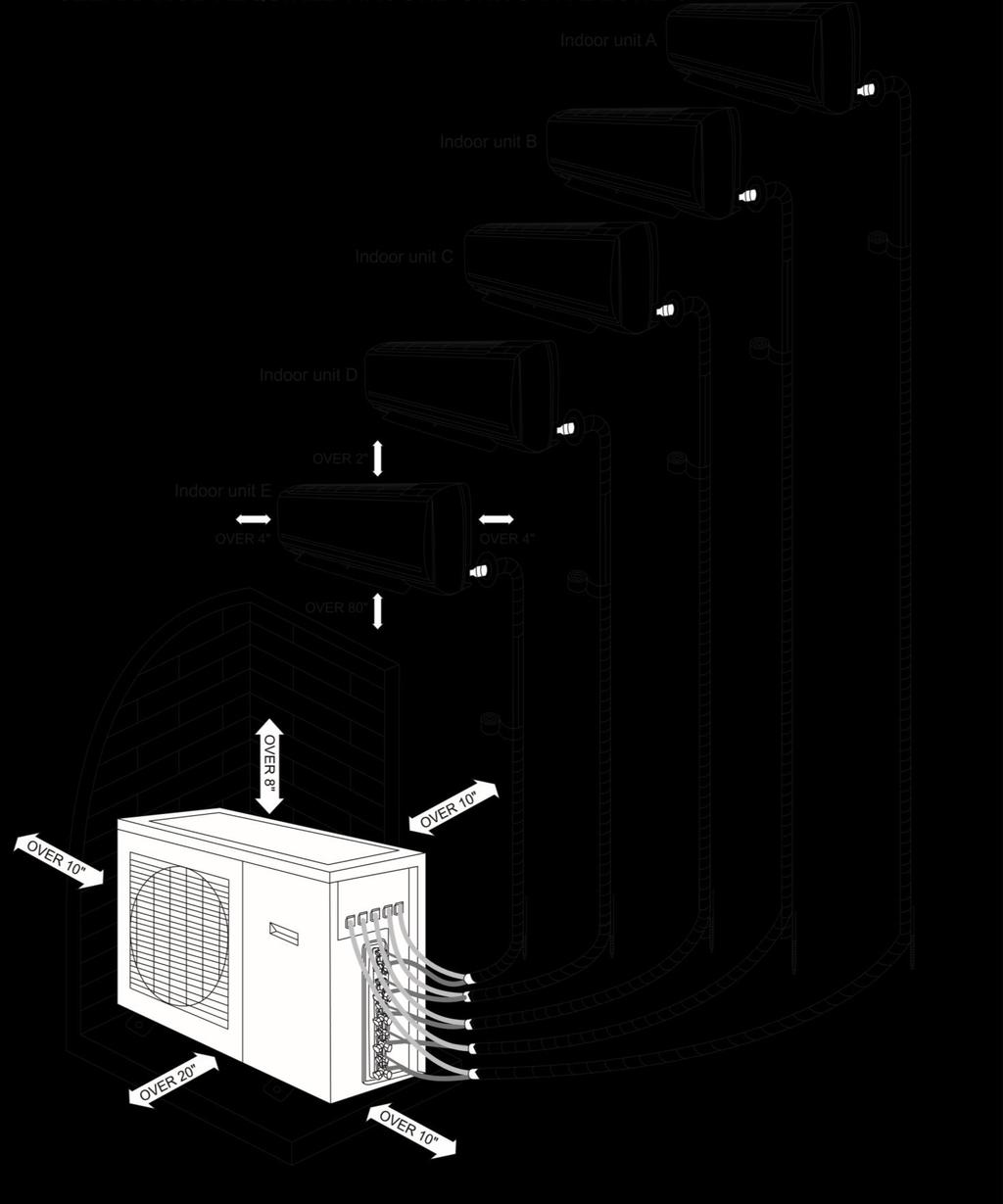
17 SYSTEM LAYOUT & INSTALLATION CLEARANCE

18 SYSTEM LAYOUT & INSTALLATION CLEARANCE

19
20
21 INSTALLATION LOCATION SELECTION All Units Shall Be Installed by Licensed Contractors or Technicians. Read Manuals before Installation. The location and structure should also be convenient for both installation and service. The location should NOT be where discharge air and noise could annoy a neighbor. The location should NOT be where drain may cause any damage to property or annoy a neighbor. The location should NOT be where brazing work may cause fire or smoke to the surrounding materials. The location should NOT be near flammable gases. The location should NOT be in or close to corrosive gases. The location should NOT be where children can access. CAUTION & SUGGESTIONS TO FOLLOW PRIOR TO INSTALLATION Check the unit for damage and missing parts or accessories. If there is damage is found or parts are found missing, call the distributor right away. Spin fan wheels or blades to check if they can rotate freely. If the fan wheel scratches the housing, call the distributor right away and do not proceed with the installation until it is fixed. Check the unit to make sure no foreign materials have been left inside the unit. Check to be sure you have all the additional parts and accessories that are required for the installation and those provided with the unit. It is strongly recommended to only use YMGI supplied or approved parts and accessories. Be sure a properly sized circuit breaker is installed for the electric power suppling the units. Pre-build the support platform on the ground or bracket for the wall before or during construction and before installation. Read installation instructions for all units thoroughly. Ask rep./distributor/ymgi Group anything you are not sure about. Get your tools and parts ready and start the installation. BASIC REQUIREMENTS FOR THE INSTALLATION LOCATION Choose a location where there are no strong heat sources, vapors, flammable gas or volatile objects. Choose a location where there are no high-frequency waves being generated by radio equipment, welders and medical equipment. Choose a location where there are not a lot of salinities, such as coastal areas. Choose a location where there is no oil (machine oil) contained in the air. Choose a location where there is no Sulfur gas present, such as areas close to hot springs. Choose a location where there is no other special circumstance. SELECTION OF INDOOR UNIT INSTALLING LOCATION The air inlet and outlet vent should be far from any obstructions, making sure that the air can be blown through the entire room. Select a location where the condensate water can be easily drained, and can be easily connected to the outdoor unit. Select a location where children cannot reach the unit. Select a location that is strong enough to support the full weight of the unit and the vibration which will allow the unit to operate more quietly. Be sure to leave enough space to allow access for routine maintenance. The height of the installed location should be 78 inches or more from the floor. Select a place about 3 feet or more away from television or any other electric appliances. Select a place where the filter can be easily maintained. Make sure that the indoor unit is installed in accordance with the dimensioned diagram.
/2/3/G 18AWG 09K 1/4 Liq. / 3/8 Gas 15/50/30/15 N(1)/2/3/G 18AWG 12K 1/4 Liq. / 1/2 Gas 15/50/30/15 N(1)/2/3/G 18AWG 18K 1/4 Liq.")
22 PIPING AND WIRING SIZES-UNITS Unit Connection Copper Pipe Sizes Min./Max. Length +/- Elevation Wires from Outdoor to Indoor Unit Min. Wire Size Outdoor Indoor Units 07K 1/4 Liq. / 3/8 Gas 15/50/30/15 N(1)/2/3/G 18AWG 09K 1/4 Liq. / 3/8 Gas 15/50/30/15 N(1)/2/3/G 18AWG 12K 1/4 Liq. / 1/2 Gas 15/50/30/15 N(1)/2/3/G 18AWG 18K 1/4 Liq. / 1/2 Gas 15/75/30/15 N(1)/2/3/G 16AWG 24K 3/8 Liq. / 5/8 Gas 15/75/30/15 N(1)/2/3/G 16AWG Fuse is Factory Installed At Indoor Control Board At Indoor Control Board At Indoor Control Board At Indoor Control Board At Indoor Control Board The indoor unit and the outdoor unit can be at different heights either above or below each other. The height for the difference must follow the stated requirements shown in the table below. Keep bending of the piping line to a minimum to avoid any possible negative impacts on the performance of the units. Make a P-trap if the elevation drop difference is more than 25 inches, as illustrated below. Refrigerant Pipe Min/Max. Length, Rise and Drop Height Btu/h Min. Length (ft.) Max. Length (ft.) Max Rise Height (ft.) Max. Drop Height (ft.) 07K - 12K K - 24K K - 36K INSTALL THE WALL MOUNTING PLATE Prior to installing the mounting plate, check the unit and make sure the unit is in good condition and ready to install. Check to make sure the installation location is strong enough to hold the weight of the whole unit and is in a location that is convenient to install, maintain, service and close to the outdoor unit. Install the indoor unit. Use enough anchor bolts to secure the mounting plates to the wall for indoor units. The mounting plate should be level and secure and ready to receive the indoor unit. Install Mounting Plate and Drill Hole for Combination of Copper Line/Wire Cable/Drain Hose NOTES: Anchors must be put into the holes, where the solid arrows are pointing, as shown, to secure the mounting plate firmly and to hold the weight of the indoor unit. If more screws/anchors are required, make sure, to keep the two holes close to each other, at least 2 inches apart. The mounting plate should be attached to the structural part of the wall. Minimum clearance, as shown, is required to ensure proper airflow and allows enough room for easier service.

.")
23 Steps to Mount Plate Mark all drill positions. At least 4 anchor holes are required, one at each perimeter corner of the plate. these are needed to secure the plate, where the bold arrows are pointing, as shown in the picture above. Refer to the specification sheet for unit weight so that enough anchors are installed at the proper locations. Pre-drill guiding holes which are marked for anchors or screws on the wall. Confirm the position of the holes and finish drilling to the depth required for anchors (NOT for screws). Align the mounting plate holes with the holes drilled on the wall and put anchors or screws into the holes to secure the mounting plate. INSTALLATION OF INDOOR UNIT DRILL 3 INCH HOLE FOR PIPING/WIRING/DRAIN Locate the center where the hole will need to be drilled. Drill the holes of Inches in diameter. A down pitch of about 1/4 inch per foot, as illustrated, is needed for the hole, to drain the condensate properly. PREPARE INDOOR UNIT- COPPER LINE SET/DRAIN HOSE If pipes need to come out of the right side (facing the front of indoor unit) of the indoor unit, snap off portion (1) on plastic casing. If pipes need to come out of the bottom side (facing the front of indoor unit) of the indoor unit, snap off portion (2) on plastic casing. If pipes need to come out of the left side (facing the front of indoor unit) of the indoor unit, snap off portion (3) on plastic casing. If pipes need to be rerouted to a different direction from the one preset at factory (towards left side, if facing the front cover of indoor unit), lay down the indoor unit on soft cushion or foam. Don't rub the plastic casing. To keep from damaging the pipes, bend the copper tubing set gently and slowly (A 90 bend should take a minimum of 10 seconds), by firmly holding the pipe at the root of the original 90 bend. Don't rub the two copper lines while bending. It is better to cut off the insulation and bend the two pipes individually and not together. If the pipes need to come out of the rear side (facing the front of the indoor unit) of the indoor unit, there is no need to snap off anything. INSTALL THE INDOOR DRAIN PIPE The drain hose must be placed beneath the copper pipes and MUST NOT be kinked or bent sharply. Do not pull the drain hose too hard, as it may break. Before passing the drain hose through the hole, wrap it with insulation to keep it from possible damage. The copper pipe and the drain hose must be wrapped with piping wrap. The insulation pad (underlay) should be used where the pipe contacts the wall.
24 REFIT DRAIN HOSE FROM THE RIGHT TO THE LEFT SIDE If the drain hose needs to be refitted from its original position (right side) to left side of the indoor unit, careful handing is necessary as not to damage the unit. Refitting method: remove the drain hose from its original position, without breaking the hose. Remove the plug at the left side. Apply water-resistant glue to fit the drain hose and the fitting before securing it. Apply water-resistant glue onto the plug and fit it back into the condensate connection at right side. NOTES: One can use a clamp to further secure the connections. HANG INDOOR UNIT Run copper set/wire cables/drain hose through the wall hole and hang the indoor unit onto the mounting plate (place the hook on the mounting plate into the hanging rib at rear side of plastic casing). Snap the plastic casing bottom into the mounting plate, gently. SHAPE THE DRAIN HOSE To drain the condensate easily, the drain hose should be angled downward (pitched towards the drain direction at 1/4" per foot). Figures below from the 2nd to 5th show some incorrect practices. The drain hose may be extended using the hose supplied with the installation list. STUFF AND SEAL THE HOLE FOR COPPER LINE SET/WIRE and CABLE/DRAIN HOSE Use putty to seal the wall hole. Use a clamp (pipe fastener) to secure the pipe at the specified location.
25 CONNECT REFRIGERANT PIPES BETWEEN THE INDOOR AND OUTDOOR UNITS First, connect the copper tubes at indoor unit. Bend the pipes accordingly using pipe bending tools. Do Not hand bend the pipes as this could kink the pipe. Extra length is required for future service. REFRIGERANT PIPES For a distance other than 25' between indoor and horizontal venting condensing units, refer to the following table for copper sizes. Refrigerant Valve and Pipe Size/Length Btu/h Valve Size Line Sizes at Different Lengths Liquid Gas ft ft. 07K 1/4, 3/8 1/4, 3/8 1/4, 3/8 09K 1/4, 3/8 1/4, 3/8 1/4, 3/8 12K 1/4, 3/8 1/4, 3/8 1/4, 3/8 18K 1/4, 1/2 1/4, 1/2 1/4, 1/2 24K 1/4, 5/8 1/4, 5/8 3/8, 5/8 Running Interconnecting Refrigerant Lines: Use clean refrigeration grade copper pipe only. Keep the copper lines from kinking and transmitting any noise to walls, cabinets, etc. Pipe length not to exceed 150 feet, elevation not to exceed 35 feet. Insulate both the liquid and gas copper lines with at least 3/8-inch-thick insulation tubes. Band, tape and secure the refrigerant lines. Support copper lines at a proper distance apart to keep the tubes from sagging. CUT REFRIGERANT PIPE Make sure where the pipe is to be cut is straight and smooth. Engage the cutting blade. The cutting blade must be straight and perpendicular to the pipe surface. Don't cut too fast or apply too much pressure. Turn and tighten the tube cutter slowly. Remove residual and de-bur the cut edge. The cut edge should be smooth and clean.

26 CONNECT REFRIGERANT PIPES: Refrigerant Pipe Length and Height Btu/h Length (ft.) Height (ft.) 07K K K K K Connect Copper Pipes-Flare/Nut Connection at Both Indoor and Outdoor Units Proper torque shall be applied to create a good connection at the female nut, flare and male nut, as recommended in the following table. Too much torque may damage and break the flare/nut seal. Too little torque may not ensure a good seal. ALWAYS use a pair of wrenches when tightening. Refrigerant Pipe Flare/Nut Connection Tightening Torque Flare Nut Tightening Torque 1/4" 3/8 25 ft. lbs. (350 kg-cm) 1/4" 1/2" 40 ft. lbs. (560 kg-cm) 1/2" 3/4" 60 ft. lbs. (840 kg-cm) 7/8 1 1/8 110 ft. lbs. (1540 kg-cm) Connect Copper Pipes-Sweat Connection In this case, wrap a wet rag around the pipe to protect the valves or other components from being overheated. When using flux, rub the tube surface using steel wool to any oxidation then clean and dry to protect the system from any possible contamination. CONNECT REFRIGERANT PIPES BETWEEN THE INDOOR AND OUTDOOR UNITS Seal Copper Line Set/Wire and Cable/Drain Hose Line Combination Run cables along with the refrigerating copper line sets and secure them with tape, 6 feet apart. Wrap tape tight (cover a third of the width of the wrapping tape applied early) to ensure a good seal. Tape and seal the end of the wrapping tape. Shape the pipe combination gently, without causing kinking, sharp bends, or other damage to it. Fix the pipe combination securely on the external wall with proper clamps, 6 feet apart. Fill the gap between the wall hole and wall sleeve with putty to keep rain or dust entering inside.
27 PIPING GUIDE Set the packed pipes in a vertical position and then unwind them slowly. Use pulley or a bending tool to ensure a safe bending radius. Do not unwind only one end of the coiled pipes. Do not make any sharp or small radius bends. May also use rolling wheel to reduce internal pipe tension and avoid possible deformation. Use an elbow tool for consistent bending radius. Do not bend long sections of pipe without using bending tools. Do not make bends that are less than 90 degrees. Maintain the minimum bending radius. Do not bend shot pipes. REMOTE CONTROL-BUTTON NAME AND FUNCTIONS NOTE 1: This is a general use remote control that can be used for numerous air conditioning model numbers. There may be some buttons on the remote that are not for use with the unit purchased. When these buttons are pressed you may hear a beep sound emitted from the remote. This will not affect the unit status. NOTE 2: Be sure there are no obstructions between the indoor unit and the remote control. Do not drop or allow any liquids near the remote. Do not place the remote in direct sunlight or any place that can become very hot. LCD Display ON/OFF MODE INCREASE (TEMP. and TIME) TURBO FAN DECREASE (TEMP. and TIME) SWING I FEEL FRESH AIR LIGHT TEMP SWEEP TIMER ON/OFF CLOCK SLEEP X-FAN
28 "SLEEP" BUTTON: This function will increase or decrease the set temperature depending on what mode the unit is running in. When SLEEP mode is turned on, while in cooling mode, the temperature will automatically increase 0.5 to 1.0 degree once every 30 minutes to one hour several times over a period of 2 hours and remain at that temperature until SLEEP mode is turned off. When SLEEP mode is turned on while in heating mode the set temp will automatically decrease 0.5 to 1.0 degree once every half to one hour for several times over a period of 2 hours and remain at that temperature until SLEEP mode is turned off. This way when the unit is in SLEEP mode during cooling the fan will blow at a lower speed to accommodate for the decreased cooling load due to less activity and a lower outdoor temperature. The same principle of savings is applied to heat mode. To activate the sleep mode, press the SLEEP button once. You will see a picture of a moon and stars in the lower left-hand corner. To turn off the SLEEP mode simply press the button once more and the moon and stars will disappear from the remote screen. "ON/OFF" BUTTON: Press this button to turn the unit on. Press once more to turn the unit off. When turning the unit ON/OFF, the TIMER, and SLEEP functions will be canceled. The preset time will remain. "MODE" BUTTON: By pressing this button you can choose what mode you would like the unit to run in. When the remote is first turned on the mode displayed will be the AUTO mode. The temperature cannot be adjusted in this mode and will not display on the indoor unit. This is a factory preset temperature of 78 F. While the unit is in AUTO mode and the room temperature drops below the factory set temp of 78 F, the unit will run in HEAT mode until that temperature is satisfied. If the room temperature rises above the set temp of 78 F, then the unit will run in COOL mode until the room temperature is satisfied. The unit itself will determine what mode to run in in-order to maintain the temperature of 78 F. Under HEAT mode the initial set temperature will be 82 F (28 C). Under other modes the initial set temp will be 77 F. "FAN" BUTTON: By pressing this button you can select from 4 different fan speeds AUTO Low Medium High. When the unit is first powered on the default fan speed setting is AUTO. When running the unit in DRY mode the fan speed will only run in low speed.
29 Note: Under the Dry Mode, the fan speed isn't adjustable, low fan speed is imperative. "CLOCK" BUTTON: The time function runs on a 24-hour clock. To set the time press the CLOCK button once. You will see a flashing clock appear on the remote. Press the "UP" button to increase the time; press the "DOWN" button to decrease the time until the desired time is set. Press the CLOCK button once more to set the time. You will notice the clock symbol is not flashing. "LIGHT" BUTTON: This allows you to turn the indoor unit display light on and off. If the light emitted by the display is not desired, simply press the LIGHT button on the remote and the display will turn off. To turn the display back on simply press the light button once more. "TURBO" BUTTON: When you press this button, you will see a symbol of a fan appear on the remote. In either heat or cooling mode, when this button is pushed the compressor and or fan will blow at a higher speed to achieve the set temp quicker. When the indoor unit senses that the set temp is being approached, the fan speed will slow down. To turn this function off simply press the TURBO button until the fan symbol is no longer displayed on the remote. "UP" Button: By pressing this button the set temperature will increase 1 each time the UP is pressed. If this button is held for more than 2 seconds, the temperature will increase more rapidly. When operating in AUTO mode the temperature cannot be changed. The temperature range for this remote is 61 F to 86 F. "DOWN" Button: By pressing this button the set temperature will increase 1 each time the - is pressed. If this button is pushed without releasing for over 2 seconds, the temperature will decrease more rapidly. In AUTO mode the temperature cannot be changed. The temperature range for this remote is 61 F to 86 F. "TEMP" Button: When the unit is first turned on the remote will display the last set temperature. When the TEMP button is pushed twice the indoor unit will display the room temperature for approximately 5 seconds before going back to the set temp. SWITCH BETWEEN F AND C : The remote default is Fahrenheit. If you would like to switch between the remote displaying Fahrenheit and Celsius the press the MODE and "DOWN" button simultaneously while the unit is turned off. "TIMER ON/OFF" BUTTON: This button allows you to set a time you would like the unit to turn on. The clock is a 24 hour clock. Press the TIMER ON/OFF button once and you will see the word "on" flashing next to a time displayed. By pressing either the UP or DOWN button, choose the time you would like the unit to turn on. Once you have the desired time displayed on the remote press the TIMER ON/OFF button once more and the word ON will stop blinking and stay on the remote. The time you would like the unit to turn on is now set. "TIMER ON/OFF" BUTTON: This allows you to set the time that you would like the unit to turn off. Simply follow the above steps but this time press the TIMER ON/OFF button instead of the TIMER ON/OFF button. When the word OFF is set on the remote screen, the time you would like the unit to turn off is now set. "SWING" BUTTON: Hold the Swing Button (symbol shown above) for more than 2 seconds and the indoor air louver will start to swing between the highest and lowest limits. Once the swing button is released the louver will stay in the last position where the button was released. If the swing button is pushed just once the swing icon will appear on the remote and the louver will swing up and down continuously between the highest and lowest points. Push the Swing Button once more and the icon will disappear on the remote and the louver will remain at the last point the button was pushed. When the unit is powered off by the remote the louver will close on the indoor unit. Press this button to set up the desired swing angle which circularly changes as below. SWING UP AND DOWN BUTTON Press this button, to set up swing angle, which circularly changes as shown below:
30 This is a universal remote control. If the remote control shows the following three kinds of status, then the swing status of main unit will be: When the guide louver starts to swing up and down and the unit is turned off the swing of the air guide louver will stop at current its position. When shown, indicates the guide louver swings up and down between all five positions. "I FEEL" BUTTON: Since the indoor unit is normally mounted high up on a wall or attached to a ceiling, the temperature where the return air sensor is installed (inside the indoor unit) is a higher temperature than occupied areas, check the air temperature (4 to 7 feet above the floor). If the unit uses the return air temperature as its target control, then the occupied areas may be colder than the target temperatures in both cooling mode and heating mode. The facts of air stratification and warm air rising, and cold air dropping will require the users to set up, by experimenting or by experience, the target temperature may be several degrees higher than what you really want, in order to reach a satisfied or more precise indoor comfort temperature. This is a common drawback of AC/HP units made by other manufacturers. With YMGI's I FEEL feature, this can be avoided, and your comfort level can be improved. When you press the I FEEL button on the remote control, the unit will use the temperature where the remote is located as its target temperature control. Once you do so, you will notice a figure of a person surrounded by stars appear on the remote. Once the I FEEL stars appear, the remote will send a signal from the remote-local temperature to the indoor unit, and the remote-local temperature will supersede the return air temperature as the unit's target temperature. Every 10 minutes a signal will be sent from the remote to the indoor unit updating the remote-local temperature. If at any time during this process no signal is received by the indoor unit from the remote, the unit will switch back to the previously set temperature before the I FEEL feature was activated. To turn the I FEEL feature off, simply press the I FEEL button until you see the symbol disappear from the remote screen. By doing so, the return air temperature will take place of remote-local temperature as the unit's target temperature. I FEEL is what YOU WANT. I FEEL feature brings to you a true comfort level wherever and whenever you want. SYMBOL DISPLAY When power is first applied to the unit, but the power has not been turned on by the remote control, the red power light only is displayed. When the unit has been powered on by the remote control the running LED is displayed and the current running mode symbol is displayed at the same time. COOLING: Running symbol and cooling symbol are displayed. HEATING: Running lamp and heating symbol are displayed. DRY: Running lamp and dry lamp are displayed. FAN: Running lamp and fan lamp are displayed. AUTO: Auto lamp, running lamp and actual running mode are displayed.
31 ALPHA NUMERIC DISPLAY The setting temperature range for the unit is 61 F to 86 F. Under AUTO mode the unit will display 77 F for cooling and 68 F for heating modes. INTRODUCTION FOR SPECIAL FUNCTION About Blow function This function indicates that there is moisture on the evaporator of the indoor unit and will continue to blow after the unit has stopped to avoid mold. 1. Having set BLOW function to on: After turning the unit off by pressing ON/OFF button, the indoor fan will continue running for about 10 minutes at low speed. While in this period, press the Blow button to stop indoor fan. 2. Having set the blow function to off: After turning the unit off by pressing ON/OFF button, the complete unit will be off. About AUTO RUN When AUTO RUN mode is selected, the setting temperature will not be displayed on the LCD, the unit will be in accordance with the room temperature automatically to select the suitable running method and to make the ambient air comfortable. About TURBO function At the start of this function, the unit will blow at a super high speed to cool or heat quickly, so the room temperature approaches the preset temperature as soon as possible. UNIT DEFROSTING CYCLE While the unit is running in HEAT mode during colder weather, frost can build up on the outdoor coil. This is common on all heat pump units made by all manufactures. If the unit is running and the automatic defrost mode is enacted the indoor unit will stop running and display an H1 code. Once the defrost cycle is finished and the outdoor coil is defrosted the indoor unit will start to run again in the mode that it was last set up for. ON DEMAND DEFROSTING If at any time you would like the send the unit into the defrost cycle, you can choose to by turning the remote controller off and pressing the BLOW and the MODE buttons simultaneously. You will see the symbol of H1 appear on the remote. To stop the defrost cycle simply press the BLOW and MODE buttons again and the H1 will disappear from the remote screen. CHANGING BATTERIES AND NOTICES 1) Press slightly along the arrowhead direction to push the back cover open on the remote control. 2) Take out the old batteries. (As show in figure) 3) Insert two new AAA1.5V dry batteries, and pay attention to the polarity. (As show in figure) 4) Attach the back cover of wireless remote control. (As show in figure) NOTE: When changing the batteries, do not use the old or different batteries, otherwise, it can cause the remote control to malfunction. The operation should be in its receiving range. It should be placed where it is 36 inches away from a TV set or stereo. If the wireless remote control cannot operate normally, please take the batteries out, wait 30 seconds and reinsert them, if the remote doesn t operate normally, please change the batteries. If the wireless remote control will not be used for an extended period, it is recommended to remove the batteries. Leaving the batteries in could cause them to leak. This will cause damage to the remote control.
32 ABOUT MODE CLASH/CONFLICT BETWEEN INDOOR UNITS If any two indoor units are controlled to run the in the following modes, the indoor unit will run into mode clash or conflict. All indoor units will stop to run and show Protection/Error code E7, unless the unit is turned-off and then turned back on: Some on HEAT Mode, while others on COOL Mode and/or DRY(Dehumidify) Mode and/or FAN Mode. NOTE: COOL mode is compatible with DRY and FAN mode. In other words, there will be no problem for some indoor units to run COOL, while others may run either one or few of modes COOL, DRY (Dehumidifying) and FAN. No Protection/Error code will show up. OPERATION AT EMERGENCY If at any time the remote control becomes damaged or lost, you can switch to Manual mode on the indoor unit. This will allow the unit to run in AUTO mode only. While in AUTO mode the unit temperature cannot be switched. Contact your local service provider for instructions on replacing the remote control. The manual switch can be operated as follow: Operation: When the unit has stopped running, press ON/OFF button, unit will enter AUTO RUN mode. The microcomputer will acquire the room temperature to select the (COOL, HEAT, FAN) mode automatically, to obtain the correct setting. Stopping: When the unit is running, press the ON/OFF button of the manual switch, the unit will stop working. The code switch can be operated as follow: Operation: When the unit has stopped running, adjust the code switch to AUTO, the unit will enter AUTO RUN mode. The microcomputer will acquire the room temperature to select the (COOL, HEAT, FAN) mode automatically, to obtain the correct setting. Stopping: When the unit is running, adjusts the code switch to the STOP position, the unit will stop working. CLEAN AND CARE Turn the unit power off and unplug the power cord before cleaning the air conditioner. Failure to do so can result in electric shock. Never sprinkle water on the indoor unit for cleaning because it can cause an electric shock. Volatile liquids (e.g. thinner or gasoline) will damage the air conditioner. (So, wipe the units with a dry soft cloth, or a cloth slightly moistened with water or a mild nonabrasive cleanser.) CLEAN THE FRONT PANEL (MAKE SURE TO TAKE IT OFF BEFORE CLEANING) Take off the front panel Along the direction of arrows, lift the front panel up, meanwhile hold both slots of the front panel and remove.
 Never use water that has a temperature above 113 F to wash the panel or it could cause deformation or discoloration.")
33 Washing Clean with a soft brush, water and neutral detergent and then dry it. (Note: Before cleaning the unit, please remove the display box first, then wash the panel. (If the unit has displayed on the front panel.) Never use water that has a temperature above 113 F to wash the panel or it could cause deformation or discoloration.) Install front panel Place two supports of the front panel into the slots, along the direction of arrows to cover and clasp the front panel. As show in figure. CLEANING THE AIR FILTERS (RECOMMENDED ONCE EVERY THREE MONTHS) Note: If the unit is in a dusty area, the air filters should be cleaned more often. After taking off the filter, be sure not to touch the fin on the indoor unit as this can cause injury.

34 To Remove the Air Filter By holding onto the bottom slot of the air filter slightly push the filter in an upward at a slight angle and pull downward carefully. Cleaning To clean the dust adhering to the filters, you can either use a vacuum cleaner, or wash them with warm water and a neutral detergent, the water should be below 113 F. When the filters have been cleaned, dry them air dry completely out of direct sunlight. NOTE: Never use water hotter than 113 F to wash the unit or the filters as this can discolor and/or deform the unit. Never dry the filters by a fire or open flame as this can be dangerous. Always air dry the filters. Reinsert the filters Reinsert the filters aligning with the arrow head, then cover the surface panel and clasp it. CHECKING BEFORE COOLING/HEATING SEASON COMES: 1. If the unit is still connected to the correct electric power V/Ph/Hz. 2. If the unit is still securely fastened. 3. If the batteries of remote control are good. 4. If the filter is loaded and clean 5. If the intake and discharge vents are clear from any obstructions. MAINTENANCE AFTER USING 1. Turn main power off, by disconnecting electrical power disconnect switch. 2. Clean filter and unit. 3. Cover the unit to keep dust or moisture out of the unit. PROTECTION AND ERROR CODES Error Code Content Error Code L0 Indoor Unit Error L9 L1 Indoor Fan Protection LA Content Quantity of Group Control Indoor Units Setting Error Indoor Units Incompatibility Error Error Code L2 E-heater Protection LH Low Air Quality Warning da L3 Water Full Protection LC L4 Wired Controller Power Supply Error D1 L5 Anti-freezing Protection D3 L7 No Master Indoor Unit Error D4 L8 db Power Insufficiency Protection Special Code: Project Debugging Code D6 dl Outdoor-Indoor Incompatibility Error Indoor Unit Circuit Board Error Ambient Temperature Sensor Error Inlet Pipe Temperature Sensor Error Outlet Pipe Temperature Sensor Error Outlet Air Temperature Sensor Error d8 d9 dh dc de C0 AJ Content Water Temperature Sensor Error Jumper Cap Error Indoor Unit Network Address Error Wired Controller Circuit Board Error Capacity DIP Switch Setting Error Indoor Unit CO2 Sensor Error Communication Error Filter Cleaning Reminding CHECKING UNITS PRIOR TO CONTACTING YOUR TECHNICIAN Do not repair the air conditioner yourself. An Incorrect repair may cause electric shock or fire, so please contact an authorized service center for professional repair.
INSTALLER'S INSTRUCTION & USER'S MANUAL
 YMGI, Engineered Comfort Products for A Sustainable and Efficient Green World! INSTALLER'S INSTRUCTION & USER'S MANUAL Wall Mount Mini Split Systems SYMPHONY SOLO DC INVERTER SINGLE ZONE (58)4 09-36k,
Installation Guide. Wind Baffle for Outdoor Units VRF-SVN079A-EN. VRF Single-Phase and C-Series Systems. October 2015 SAFETY WARNING
 Installation Guide Wind Baffle for Outdoor Units VRF Single-Phase and C-Series Systems Model Numbers: CSERWINDBFL1AA CSERWINDBFL24AA CSERWINDBFL36AA SAFETY WARNING Only qualified personnel should install
Variable Refrigerant Flow (VRF) System Simple Touch Remote Control SAFETY WARNING
 System Simple Touch Remote Control SAFETY WARNING") User Guide Variable Refrigerant Flow (VRF) System Simple Touch Remote Control Model Numbers: TVCTRLTWR0002T TVCTRLTWR0002A SAFETY WARNING Only qualified personnel should install and service the equipment.
User Guide Variable Refrigerant Flow (VRF) System Simple Touch Remote Control Model Numbers: TVCTRLTWR0002T TVCTRLTWR0002A SAFETY WARNING Only qualified personnel should install and service the equipment.
Combination Cooling/Gas Heat Package Units
 User s Manual Combination Cooling/Gas Heat Package Units YSC036E* YHC036E* YSC048E* YHC048E* YSC060E* YHC060E* YSC072E* YHC072E* YSC090E* YHC092E* YSC092E* YHC102E* YSC102E* YHC120E* YSC120E* July 2009
TABLE OF CONTENTS. NOTE: Read the entire instruction manual before starting the installation. TROUBLESHOOTING... 13
 R 410A Duct Free Split System Air Conditioner and Heat Pump Product Family: DFS4(A/H) System, DFC4(A/H)3 Outdoor, DFF4(A/H)H Indoor NOTE: Read the entire instruction manual before starting the installation.
Installation Instructions
 40MAQ High Wall Ductless Split System Sizes 09 to 36 Installation Instructions NOTE: Read the entire instruction manual before starting the installation TABLE OF CONTENTS PAGE SAFETY CONSIDERATIONS 2 PARTS
Installation Instructions
 38MHR Outdoor Unit Single Zone Ductless System Sizes 09 to 24 Installation Instructions NOTE: Read the entire instruction manual before starting the installation. NOTE: Images are for illustration purposes
Installation Instructions
 40MBFQ Floor Console Ductless System Sizes 09 to 12 Installation Instructions TABLE OF CONTENTS PAGE SAFETY CONSIDERATIONS... 2 PARTS LIST... 3 SYSTEM REQUIREMENTS... 4 DIMENSIONS... 5 CLEARANCES... 5
DLCLRA. INSTALLATION INSTRUCTIONS Outdoor Unit Single Zone Ductless System Sizes 36 to 58 TABLE OF CONTENTS
 DLCLRA INSTALLATION INSTRUCTIONS Outdoor Unit Single Zone Ductless System Sizes 36 to 58 Fig. 1 - Size 36 TABLE OF CONTENTS PAGE SAFETY CONSIDERATIONS... 2 PARTS LIST... 3 SYSTEM REQUIREMENTS... 4 WIRING...
Installation Instructions
 40MBFQ Floor Console Ductless System Sizes 09 to 58 Installation Instructions TABLE OF CONTENTS PAGE SAFETY CONSIDERATIONS... 2 PARTS LIST... 3 SYSTEM REQUIREMENTS... 4 WIRING... 4 DIMENSIONS... 5 CLEARANCES...
HEAT PUMP INSTALLATION MANUAL
 DUCTLESS INVERTER HEAT PUMP INSTALLATION MANUAL Models: TERRA09HP230V1A TERRA12HP230V1A TERRA18HP230V1B TERRA24HP230V1B Thank you for choosing a Gree Terra Ductless Heat Pump for your customer. Please
Installation Instructions
 8GXM / 0GXM Multi---Split High---Wall Duct Free Split System 8GXM --- Size 18k, k, and 0k 0GXM --- Size 9k, 1k, and 18k Installation Instructions NOTE: Read the entire instruction manual before starting
User s Manual WS-63TB36SS WS-63TB42SS NOTE: PLEASE INSPECT HOOD IMMEDIATELY UPON RECEIVING. CLAIM OF DAMAGE AFTER 7 DAYS OF DELIVERY WILL BE DENIED.
 www.windsterhood.com User s Manual WS-63TB36SS WS-63TB42SS ISLAND SERIES NOTE: PLEASE INSPECT HOOD IMMEDIATELY UPON RECEIVING. CLAIM OF DAMAGE AFTER 7 DAYS OF DELIVERY WILL BE DENIED. This unit is designed
AIR CONDITIONER OWNER S MANUAL. Please read this manual carefully before operating your set and retain it for future reference.
 ENGLISH OWNER S MANUAL AIR CONDITIONER Please read this manual carefully before operating your set and retain it for future reference. Ceiling Suspended Original instruction ARNU18GV1A4 ARNU24GV1A4 ARNU36GV2A4
Horizontal/Side Discharge Condensing Units
 INSTALLATION, OPERATION & MAINTENANCE MANUAL Horizontal/Side Discharge Condensing Units Models CMA12SD-0 CMA18SD-1 CMA24SD-1 CMA30SD-1 CMA36SD-1 CMA48SD-1 517.787.2100 www.marsdelivers.com Horizontal/Side
User s Manual WALL MOUNT SERIES TABLE OF CONTENTS RA7730SS/RA77B30SS RA7736SS/RA77B36SS RA7742SS/RA77B42SS RA7748SS/RA77B48SS.
 TABLE OF CONTENTS 1 Table of Contents www.windsterhood.com Safety Information... 2 3 WALL MOUNT SERIES User s Manual RA7730SS/RA77B30SS RA7736SS/RA77B36SS RA7742SS/RA77B42SS RA7748SS/RA77B48SS NOTE: PLEASE
General safety precautions English
 English 1 1 1.1 About the documentation The original documentation is written in English. All other languages are translations. The precautions described in this document cover very important topics, follow
User s Manual WS-62N30SS WS-62N36SS NOTE: PLEASE INSPECT HOOD IMMEDIATELY UPON RECEIVING. CLAIM OF DAMAGE AFTER 7 DAYS OF DELIVERY WILL BE DENIED.
 WALL MOUNT SERIES www.windsterhood.com User s Manual WS-62N30SS WS-62N36SS NOTE: PLEASE INSPECT HOOD IMMEDIATELY UPON RECEIVING. CLAIM OF DAMAGE AFTER 7 DAYS OF DELIVERY WILL BE DENIED. This unit is designed
Portable Dehumidifier with Internal Pump
 Portable Dehumidifier with Internal Pump OPERATING INSTRUCTIONS 115 Pint Portable Dehumidifier With Internal Pump Model Number: DMC-115IP-210 3092402 V161220 PURCHASE INFORMATION Thank you for choosing
Ductless Split Air Conditioner
 Ductless Split Air Conditioner Installation Manual Indoor HSU09VHG(DB)-W HSU12VHG(DB)-W HSU18VHH(DB)-W HSU24VHG(DB)-W Outdoor HSU09VHG(DB)-G HSU12VHG(DB)-G HSU18VHH(DB)-G HSU24VHG(DB)-G Table of Contents
IOM & Owner s Manual. VFH-B Series. Inverter Multi Zone Ductless Mini-Split A-VFH18DB-1 A-VFH24TB-1.
 IOM & Owner s Manual VFH-B Series Inverter Multi Zone Ductless Mini-Split A-VFH18DB-1 A-VFH24TB-1 www.marsdelivers.com In line with the MARS policy of continual product improvement, the aesthetic and dimensional
Table of Contents. Safety Information Content Checklist Measurements Preparation Installation
 TABLE OF CONTENTS 1 Table of Contents Safety Information... 2 3 Content Checklist... 4 Measurements... 5 Preparation... 6 Installation... 7 8 Installation Diagram... 9 Operation & Features... 10 Cleaning
INSTALLATION INSTRUCTIONS
 INSTALLATION INSTRUCTIONS - Wall-mount indoor unit - OPERATING LIMITS Cooling Maximum conditions Heating Maximum conditions Outdoor temperature : 122 F (50 C) D.B. Outdoor temperature : 75 F (24 C) D.B.
General safety precautions English
 English A min (m 2 ) 550 530 540 510 520 490 500 470 480 450 460 430 440 410 420 390 400 370 380 350 360 330 340 310 320 290 300 270 280 250 260 230 240 210 220 190 200 170 180 150 160 130 140 110 120
General safety precautions English
 English A min (m 2 ) 550 530 540 510 520 490 500 470 480 450 460 430 440 410 420 390 400 370 380 350 360 330 340 310 320 290 300 270 280 250 260 230 240 210 220 190 200 170 180 150 160 130 140 110 120
General safety precautions English
 English 1 1 Units are marked with the following symbol: 1.1 About the documentation The original documentation is written in English. All other languages are translations. The precautions described in
User s Manual ISLAND SERIES TABLE OF CONTENTS RA-7630SS RA-7636SS RA-7642SS RA-7648SS. Table of Contents. Safety Information...
 - TABLE OF CONTENTS Table of Contents 1 www.windsterhood.com Safety Information... 2 3 ISLAND SERIES User s Manual RA-7630SS RA-7636SS RA-7642SS RA-7648SS NOTE: PLEASE INSPECT HOOD IMMEDIATELY UPON RECEIVING.
Owner s Manual Window Air Conditioner
 Owner s Manual Window Air Conditioner G17-5MCVWAC1 G16-5MCVWAC Write the model and serial numbers below for your records: Model # Serial # Date Purchased Please read the entire manual carefully to ensure
INSTALLATION MANUAL. Split-type Air Conditioner (Cooling and Heating) Outdoor Unit UQB09JJWC UQB12JJWC. Indoor Unit AQB09JJWC AQB12JJWC
 Outdoor Unit UQB09JJWC UQB12JJWC. Indoor Unit AQB09JJWC AQB12JJWC") AQB09JJ6WC_IM_E_2585 2006.4.17 4:26 PM Page 17 INSTALLATION MANUAL Indoor Unit AQB09JJWC AQB12JJWC Outdoor Unit UQB09JJWC UQB12JJWC ENGLISH FRANÇAIS ESPAÑOL Split-type Air Conditioner (Cooling and Heating)
AQB09JJ6WC_IM_E_2585 2006.4.17 4:26 PM Page 17 INSTALLATION MANUAL Indoor Unit AQB09JJWC AQB12JJWC Outdoor Unit UQB09JJWC UQB12JJWC ENGLISH FRANÇAIS ESPAÑOL Split-type Air Conditioner (Cooling and Heating)
Owner s Information Manual
 48ES---A and 48VL---A Comfort and Performance 13 and 14 SEER Single Packaged Air Conditioner and Gas Furnace System With Puron (R---410A) Refrigerant Single and Three Phase 2---5 Nominal Tons (Sizes 24---60)
General safety precautions English
 English 1 1 1.1 About the documentation The original documentation is written in English. All other languages are translations. The precautions described in this document cover very important topics, follow
12 VELOCITY OWNER S MANUAL OPERATING INSTRUCTIONS - MAINTENANCE - SAFETY - TROUBLESHOOTING
 12 VELOCITY OWNER S MANUAL OPERATING INSTRUCTIONS - MAINTENANCE - SAFETY - TROUBLESHOOTING This manual contains very important safety warnings and information. Read and save these instructions for future
Fig. 1 - Unit PGD4, PGS4, WPG4
 OWNER S MANUAL 14 SEER Single -Package Air Conditioner and Gas Furnace System with R -410A Refrigerant Single Phase 2 to 5 Nominal Tons Three Phase 3 to 5 Nominal Tons PGD4andPGS4SeriesE,WPG4SeriesB Fig.
MN908 No. 282C Replaces 282B LB7013
 No. 282C Replaces 282B LB7013 Instruction Manual For Baldor Dust Control Units Models DC7, DC7 3, DC8, DC8 3, DC10, DC10 3, DC12, DC12 3 and DC14 3. For use on Grinders mounted to GA16 and GA20 pedestals
Sunleaves Air Conditioner
 Sunleaves Air Conditioner Thank you for purchasing this quality Sunleaves Air Conditioner! Please read through this manual completely, and keep it in case you need to reference the information in the future.
INSTALLATION MANUAL. Split-type Air Conditioner (Cooling and Heating) Indoor Unit AQB18J6WC AQB24J2WC. Outdoor Unit UQB18J6WC UQB24J2WC
 Indoor Unit AQB18J6WC AQB24J2WC. Outdoor Unit UQB18J6WC UQB24J2WC") AQB8J6WC_IM_E_25864 2006.4.4 3:29 PM Page 7 INSTALLATION MANUAL Indoor Unit AQB8J6WC AQB24J2WC Outdoor Unit UQB8J6WC UQB24J2WC ENGLISH FRANÇAIS ESPAÑOL Split-type Air Conditioner (Cooling and Heating)
AQB8J6WC_IM_E_25864 2006.4.4 3:29 PM Page 7 INSTALLATION MANUAL Indoor Unit AQB8J6WC AQB24J2WC Outdoor Unit UQB8J6WC UQB24J2WC ENGLISH FRANÇAIS ESPAÑOL Split-type Air Conditioner (Cooling and Heating)
Portable Dehumidifier
 Portable Dehumidifier OPERATING INSTRUCTIONS HMT-D30-A Model Numbers: HMT-D30-A HMT-D45E-A HMT-D70E-A HMT-D45E-A HMT-D70E-A 3058080 V.161115 PURCHASE INFORMATION Thank you for choosing a Soleus Air Portable
Installation Instructions
 40MHH High Wall Ductless System Sizes 09 to 24 Installation Instructions NOTE: Read the entire instruction manual before starting the installation. NOTE: Images are for illustration purposes only. Actual
General safety precautions English
 General safety precautions General safety precautions English 1 General safety precautions 1 General safety precautions Units are marked with the following symbol: 1.1 About the documentation The original
High-Velocity Floor Fan
 High-Velocity Floor Fan Owner s Manual WARNING: Read carefully and understand all ASSEMBLY AND OPERATION INSTRUCTIONS before operating. Failure to follow the safety rules and other basic safety precautions
WMHP Series R410a Heat Pump INSTALLATION INSTRUCTIONS
 WMHP Series R410a Heat Pump INSTALLATION INSTRUCTIONS **WARNING TO INSTALLER, SERVICE PERSONNEL AND OWNER** Altering the product or replacing parts with non authorized factory parts voids all warranty
Owner s Manual. VFH-B Series. Inverter Multi Zone Ductless Mini-Split A-VFH18DB-1 A-VFH24TB-1.
 Owner s Manual VFH-B Series Inverter Multi Zone Ductless Mini-Split A-VFH18DB-1 A-VFH24TB-1 www.marsdelivers.com In line with the policy of continual product improvement, the aesthetic and dimensional
OWNER S MANUAL. Portable Air Conditioner. Product defect? Not working properly? DO NOT return this product to the store where you purchased it.
 Product defect? Not working properly? DO NOT return this product to the store where you purchased it. Contact Ideal Air Support directly at support@ideal-air.com or call -877-9- IDEAL- For answers to the
INSTALLATION INSTRUCTIONS
 INSTALLATION INSTRUCTIONS C8DA Series Split System Uncased Indoor Coils - Downturn IMPORTANT ATTENTION INSTALLERS: It is your responsibility to know this product better than your customer. This includes
Portable Air Conditioner, Dehumidifier,Heater and Fan utilizing Heat Pump Technology
 Portable Air Conditioner, Dehumidifier,Heater and Fan utilizing Heat Pump Technology OWNER'S MANUAL Model # KY-34 3046364 Please read owner s manual carefully before operating unit. TABLE OF CONTENTS INTRODUCTION...3
INSTALLATION MANUAL COMFORT...BUILT TO LAST. 9,000, 12,000 and 18,000 BTU SINGLE-ZONE DUCTLESS MINI-SPLIT SYSTEM Heat Pump
 COMFORT...BUILT TO LAST 9,000, 12,000 and 18,000 BTU SINGLE-ZONE DUCTLESS MINI-SPLIT SYSTEM Heat Pump INSTALLATION MANUAL INDOOR UNIT: 1PAMSH09-SZW-14.5 1PAMSH09-SZW-15 1PAMSH12-SZW-15 1PAMSH18-SZW-15
Installation GUIDE VDWU524SS VDWU524WSSS FDWU524WS FDWU524 VDWU324SS FDWU324
 Installation GUIDE VDWU524SS VDWU524WSSS FDWU524WS FDWU524 VDWU324SS FDWU324 To prevent accidents, which could cause serious injury or death, as well as machine damage read these instructions before installation
UNDERCOUNTER REFRIGERATORS AND FREEZERS Installation, Operation and Maintenance Instructions
 UNDERCOUNTER REFRIGERATORS AND FREEZERS Installation, Operation and Maintenance Instructions Please read this manual completely prior to installing and operating this equipment. This manual describes how
HMT-D30-A HMT-D45E-A HMT-D70E-A. Model Numbers: HMT-D30-A HMT-D45E-A HMT-D70E-A. Portable Dehumidifier Operating Instructions V.
 HMT-D30-A HMT-D45E-A HMT-D70E-A Model Numbers: HMT-D30-A HMT-D45E-A HMT-D70E-A Portable Dehumidifier Operating Instructions 3119233 V.141217 General Dehumidifier Information RECOMMENDED HUMIDITY LEVELS
Installation Instructions
 38MPRA Outdoor Unit Single Zone Ductless System Sizes 09 to 12 Installation Instructions NOTES: Read the entire instruction manual before starting the installation. Images are for illustration purposes
VENTILATION FAN WITH LED LIGHT AND HEATER MODEL RAD110LED
 VENTILATION FAN WITH LED LIGHT AND HEATER MODEL RAD110LED TABLE OF CONTENTS Package Contents Important Instructions Preparation Assembly Instructions Wiring Instructions Operating Instructions Care and
INSTALLATION INSTRUCTIONS Cased N Coil, Horizontal ENH4X
 INSTALLATION INSTRUCTIONS Cased N Coil, Horizontal ENH4X NOTE: Read the entire instruction manual before starting the installation. TABLE OF CONTENTS PAGE SAFETY CONSIDERATIONS... 1 INTRODUCTION... 1 INSTALLATION...
DUCTED AIR CONDITIONER. Owner s Manual. KD Series KD24. Kaden Owner s Manual 1
 DUCTED AIR CONDITIONER Owner s Manual KD Series KD24 Kaden Owner s Manual 1 Table of Contents 1. Safety Precautions 4 2. Indoor Unit Parts and Major Functions 6 3. Care and Maintenance 8 4. Troubleshooting
User s Manual RA-3030SS RA-3036SS. NOTE: This unit was designed for indoor residential use and DUCTED operation only.
 www.windsterhood.com User s Manual UNDER CABINET SERIES RA-3030SS RA-3036SS NOTE: This unit was designed for indoor residential use and DUCTED operation only. DO NOT USE OVER A WOOD GRILL OR MOUNT OUTDOOR
Installation Instructions
 40MAQ High Wall Ductless System Sizes 09 to 36 Installation Instructions NOTES: Read the entire instruction manual before starting the installation. Images are for illustration purposes only. Actual models
SINGLE - ZONE Ductless Split System Heat Pumps Installation, Operation & Maintenance Manual
 Presents SINGLE - ZONE Ductless Split System Heat Pumps Installation, Operation & Maintenance Manual 9k,12k 18k 24k, 30k, 36k ECR International, Inc. 2201 Dwyer Avenue, Utica NY 13501 Phone: 800.325.5479
DISHWASHER. Models DW2432 and DW2432SS. Installation Manual. Write Serial Number (on inner door of unit) here:
 here:") DISHWASHER Models DW2432 and DW2432SS Installation Manual Write Serial Number (on inner door of unit) here: Felix Storch, Inc. Summit Appliance Division 770 Garrison Avenue Bronx, New York 10474 www.summitappliance.com
DISHWASHER Models DW2432 and DW2432SS Installation Manual Write Serial Number (on inner door of unit) here: Felix Storch, Inc. Summit Appliance Division 770 Garrison Avenue Bronx, New York 10474 www.summitappliance.com
AC Portable Air Conditioner AC-14100E, AC-14100H OWNERS MANUAL. Read and save these instructions.
 AC-14100 Portable Air Conditioner AC-14100E, AC-14100H OWNERS MANUAL Read and save these instructions. 2 A Name You Can Trust Trust has to be earned and we will earn yours. Customer happiness is the focus
Model No. GB-PAC-08E4. 8,000 BTU Portable Air Conditioner Operating Instructions
 Model No. GB-PAC-08E4 8,000 BTU Portable Air Conditioner Operating Instructions Thank you for choosing a Soleus Air Powered by Gree Portable Air Conditioner. This owner s manual will provide you with valuable
Inverter Air Source Heat Pump Monobloc system
 Inverter Air Source Heat Pump Monobloc system Product Data & Installation Manual AXAI-06M & AXAI-09M AXAI-12M & AXAI-15M TABLE OF CONTENT INSTRUCTIONS 1 This manual 1 Items inside product box. 2 Tools
HMT-D30-A HMT-D45E-A HMT-D70E-A. Model Numbers: HMT-D30-A HMT-D45E-A HMT-D70E-A. Portable Dehumidifier Operating Instructions V.
 HMT-D30-A HMT-D45E-A HMT-D70E-A Model Numbers: HMT-D30-A HMT-D45E-A HMT-D70E-A Portable Dehumidifier Operating Instructions 3058080 V.151201 General Dehumidifier Information RECOMMENDED HUMIDITY LEVELS
C7 Series Split System Uncased Indoor Coils
 Installation Instructions C7 Series Split System Uncased Indoor Coils IMPORTANT ATTENTION INSTALLERS: It is your responsibility to know this product better than your customer. This includes being able
Refrigerant Recovery Machine. Model No Operating Manual
 Refrigerant Recovery Machine Model No. 25700 Operating Manual Safety Precautions WARNING : TO PREVENT PERSONAL INJURY AND / OR EQUIPMENT DAMAGE, CAUTION - Risk of injury. This equipment should only be
PARALLEL RACK SYSTEM INSTALLATION & OPERATIONS MANUAL With Master Rack Compressor Sequencer
 PARALLEL RACK SYSTEM INSTALLATION & OPERATIONS MANUAL With Master Rack Compressor Sequencer 5/16 Rev. A 57-02509 2 Contents INTRODUCTION... 4 WARNING LABELS AND SAFETY INSTRUCTIONS... 5 PS SERIES PARALLEL
REFRIGERATED PREP TABLES Installation, Operation and Maintenance Instructions
 REFRIGERATED PREP TABLES Installation, Operation and Maintenance Instructions Please read this manual completely prior to installing and operating this equipment. This manual describes how to install,
INSTRUCTION MANUAL. UNDERCOUNTER WINE & BEVERAGE COOLER (32 bottles capacity) MODEL:WC-30U
 MODEL:WC-30U") INSTRUCTION MANUAL UNDERCOUNTER WINE & BEVERAGE COOLER (32 bottles capacity) MODEL:WC-30U To ensure proper use of this appliance and your safety, please read the following instructions completely before
INSTRUCTION MANUAL UNDERCOUNTER WINE & BEVERAGE COOLER (32 bottles capacity) MODEL:WC-30U To ensure proper use of this appliance and your safety, please read the following instructions completely before
ELECTRIC HEDGE TRIMMER
 ELECTRIC HEDGE TRIMMER 60-3014-6 Owner's Manual TOLL-FREE HELPLINE: 1 866 523-5218 IMPORTANT: Read all safety rules and instructions carefully before using this product. TABLE OF CONTENTS SPECIFICATIONS...
Owner s Manual Super-Slim Four-Way Cassette
 CASSETTE- TYPE AIR CONDITIONER Owner s Manual Super-Slim Four-Way Cassette IMPORTANT NOTE: Read this manual carefully before installing or operating your new air conditioning unit. Make sure to save this
Packaged Rooftop Air Conditioners Precedent - Cooling, Gas/Electric, Heat Pump 3-5Ton Standard and High Efficiency 3 Phase Rooftop Units
 Service Facts Packaged Rooftop Air Conditioners Precedent - Cooling, Gas/Electric, Heat Pump 3-5Ton Standard and High Efficiency 3 Phase Rooftop Units Model Numbers TSC036E3,4,W YSC036E3,4,W WSC036E3,4,W
R32. Installation Manual Split Type Wall Mounted Air Conditioner. This appliance shall be installed in accordance with: REFRIGERANT
 SWING LRSWING Installation Manual Split Type Wall Mounted Air Conditioner COOL RUN C SPEED TURBO ON/OFF FAN COOL HEAT SWING SWING Rinnai Systems Models System Indoor Outdoor HSNRQ25B HINRQ25B HONRQ25B
11,000 BTU Portable Air Conditioner with dehumidifier & Fan PE4-11R-03 Operating Instructions. Model No. PE4-11R Soleus Air International
 11,000 BTU Portable Air Conditioner with dehumidifier & Fan PE4-11R-03 Operating Instructions Model No. PE4-11R-03 2006 Soleus Air International Thank you for choosing a Soleus Air Portable Air Conditioner.
Installation Instructions Remote Blowers
 Installation Instructions Remote Blowers Models: REMP3, REMP16 Suitable for use in a household cooking area. Suitable for use with solid state controls. To complete this blower, a Dacor hood assembly or
DLCSRA. INSTALLATION INSTRUCTIONS Outdoor Unit Ductless Split System Sizes 09 to 36 TABLE OF CONTENTS
 DLCSRA INSTALLATION INSTRUCTIONS Outdoor Unit Ductless Split System Sizes 09 to 36 NOTES: Read the entire instruction manual before starting the installation. Images are for illustration purposes only.
MODEL 7000 SUCTION UNIT
 MODEL 7000 SUCTION UNIT OPERATOR S MANUAL Caution Federal law restricts this device to sale by or on order of a physician, or any other practitioner licensed by the law of the State in which he practices
INSTALLATION INSTRUCTIONS Cased N Coil, Horizontal ENH4X
 INSTALLATION INSTRUCTIONS Cased N Coil, Horizontal ENH4X NOTE: Read the entire instruction manual before starting the installation. TABLE OF CONTENTS PAGE SAFETY CONSIDERATIONS... 1 INTRODUCTION... 1 INSTALLATION...
POLAR TEMP FARM MORTALITY UNIT OPERATION MANUAL
 POLAR TEMP FARM MORTALITY UNIT OPERATION MANUAL www.polartemp.com TABLE OF CONTENT Disclaimer.......................................... Page 3 Inspection, unpacking and FMU setup.................. Page
AIR CONDITIONER OWNER S MANUAL. Please read this manual carefully before operating your set and retain it for future reference.
 ENGLISH FRANÇAIS ESPAÑOL OWNER S MANUAL AIR CONDITIONER Please read this manual carefully before operating your set and retain it for future reference. TYPE : Ceiling Cassette - 2Way http://www.lghvac.com
Inverter Split-type Room Air Conditioner
 OWNER S MANUAL Inverter Split-type Room Air Conditioner Please read the operating instructions and safety precautions carefully and thoroughly before installing and operating your room air conditioner.
AUTO COOL DRY FAN SPEED AIR SWING OFF ON TIMER TIMER OFF/ON FAN SPEED MODE TEMP AIR SWING TIMER ON SET OFF CANCEL AC RC SET CHECK CLOCK RESET
 AUTO COOL DRY MODE TIMER ON OFF TIMER OFF/ON TEMP ON TIMER FAN SPEED AIR SWING SET 1 2 3 FAN SPEED AIR SWING OFF CANCEL AC RC SET CHECK CLOCK RESET Order No: PAPAMY1611008CE Indoor Unit CS-MPS9SKH CS-MPS12SKH
User s Manual. NOTE: This unit does not support ducted operation. For ducted operation, please refer to model WS208L30SS or WS208L36SS
 www.windsterhood.com User s Manual UNDER CABINET SERIES WS-208LF30SS WS-208LF36SS NOTE: This unit does not support ducted operation. For ducted operation, please refer to model WS208L30SS or WS208L36SS
Owner s Manual. Middle Static Pressure Duct Type MEU-18MPH2 MEU-24MPH2 MEU-36MPL2 MEU-48MPL2 MIDDLE STATIC PRESSURE DUCT TYPE AIR CONDITIONER
 MIDDLE STATIC PRESSURE DUCT TYPE AIR CONDITIONER Owner s Manual Middle Static Pressure Duct Type MEU-18MPH2 MEU-24MPH2 MEU-36MPL2 MEU-48MPL2 IMPORTANT NOTE: Read this manual carefully before installing
GL-DEH Series Portable Dehumidifier Operating Instructions
 GL-DEH Series Portable Dehumidifier Operating Instructions General Dehumidifier Information RECOMMENDED HUMIDITY LEVELS ACCORDING TO ENERGY STAR Spring/Summer: 30% - 50% Fall/Winter: 30% - 40% EMPTYING
MAYFIELD CEILING FAN LISTED E ITEM # MODEL #BTH44ABZC5C BTH44BNK5C Español p. 20 ATTACH YOUR RECEIPT HERE.
 Harbor Breeze is a registered trademark of LF, LLC. All Rights Reserved. ITEM #0331094 0331096 MAYFIELD CEILING FAN MODEL #BTH44ABZC5C BTH44BNK5C Español p. 20 ATTACH YOUR RECEIPT HERE Serial Number Purchase
Owner s Information Manual
 50EZ---A and 50VT ---A Comfort and Performance 13 and 14 SEER Single Packaged Heat Pump System With PuronR (R ---410A) Refrigerant Single and Three Phase 2---5 Nominal Tons (Sizes 24---60) Owner s Information
Comparative Enthalpy Kit
 Installer s Guide Comparative Enthalpy Kit Models: BAYENTH008B Used With: 12 1/2-25 Ton Packaged Rooftop units with Reliatel Communications Module June 2010 ACC-SVN30B-EN Warnings, Cautions and Notices
INSTALLATION INSTRUCTIONS
 C7BA & C7BH Series Split System Indoor Cased Coils INSTALLATION INSTRUCTIONS IMPORTANT It is your responsibility to know this product better than your customer. This includes being able to install the
User s Manual WS-4830SS WS-4836SS NOTE: PLEASE INSPECT HOOD IMMEDIATELY UPON RECEIVING. CLAIM OF DAMAGE AFTER 7 DAYS OF DELIVERY WILL BE DENIED.
 www.windsterhood.com User s Manual UNDER CABINET SERIES WS-4830SS WS-4836SS NOTE: PLEASE INSPECT HOOD IMMEDIATELY UPON RECEIVING. CLAIM OF DAMAGE AFTER 7 DAYS OF DELIVERY WILL BE DENIED. This unit is designed
Portable Air Conditioner with Heat Pump Technology Operating Instructions. Model No.: HCB-P13HP-D. Reference No.: BPD13HP V140217
 Portable Air Conditioner with Heat Pump Technology Operating Instructions 3092402 Model No.: HCB-P13HP-D Reference No.: BPD13HP V140217 Thank you for choosing a Soleus Air Portable Air Conditioner with
FLCH4R Garage and Utility Electric Heater
 FLCH4R Garage and Utility Electric Heater Installation, Operation & Maintenance Instructions Model No. Volts Amps Watts BTU/HR Phase High Low High Low High Low Min Fuse Size* FLCH4R 208 17.3 8.66 3600
5) Do not start or stop the unit by inserting or pulling out the power plug.
 Do not start or stop the unit by inserting or pulling out the power plug.") 3058080 V170306 PURCHASE INFORMATION Thank you for choosing a Soleus Air Portable Air Conditioner. This Owner s Manual will provide you with valuable information necessary for the proper care and maintenance
3058080 V170306 PURCHASE INFORMATION Thank you for choosing a Soleus Air Portable Air Conditioner. This Owner s Manual will provide you with valuable information necessary for the proper care and maintenance
Split Air Conditioner
 Change for Life Split Air Conditioner Installation Manual Residential Air Conditioners MODEL: GWC09AB-D3DNA2D GWC12AB-D3DNA2D GWC18AC-D3DNA2D GWC24AC-D3DNA2D GWH09AB-D3DNA2D GWH12AB-D3DNA2D GWH18AC-D3DNA2D
HI Industrial Utility Heater HI Soleus Air International
 HI1-50-03 Industrial Utility Heater HI1-50-03 2010 Soleus Air International Thank you for choosing a Soleus Air Utility Heater. This owner s manual will provide you with valuable information necessary
NOTE: All the illustrations in this manual are for explanation purposes only. Your air conditioner may be slightly different.
 RADS-51J RADS-61J Owner s Manual Room Air Conditioner with R-410A Heat Controller, Inc. 15 16 Contact an authorized service technician for repair or maintenance of this unit. Contact an authorized installer
INSTALLATION INSTRUCTIONS
 INSTALLATION INSTRUCTIONS C7BA Series Split System Indoor Cased Coils IMPORTANT ATTENTION INSTALLERS: It is your responsibility to know this product better than your customer. This includes being able
WS-5530SS WS-5536SS WS-5542SS NOTE: PLEASE INSPECT HOOD IMMEDIATELY UPON RECEIVING. CLAIM OF DAMAGE AFTER 7 DAYS OF DELIVERY WILL BE DENIED.
 www.windsterhoocom UNDER CABINET SERIES User s Manual WS-5530SS WS-5536SS WS-5542SS NOTE: PLEASE INSPECT HOOD IMMEDIATELY UPON RECEIVING. CLAIM OF DAMAGE AFTER 7 DAYS OF DELIVERY WILL BE DENIED. This unit
Installation Instructions
 CNPHP Cased N Coils Horizontal Heating --- Cooling NOTE: Read the entire instruction manual before starting the installation. TABLE OF CONTENTS PAGE SAFETY CONSIDERATIONS... 1 INTRODUCTION... 1 INSTALLATION...
WHYNTER Compressor Cooling Beverage Refrigerator - Stainless Steel
 WHYNTER Compressor Cooling Beverage Refrigerator - Stainless Steel Model Number: JC-88 MODEL# : BR-125SD Instruction Manual Thank you for your purchase of this WHYNTER product. Please read this Instruction
Model Numbers: HCT-D30-A (TDA30) HCT-D45E-A (TDA45E) HCT-D70E-A (TDA70E) Portable Dehumidifier Operating Instructions V
 HCT-D45E-A (TDA45E) HCT-D70E-A (TDA70E) Portable Dehumidifier Operating Instructions V") Model Numbers: HCT-D30-A (TDA30) HCT-D45E-A (TDA45E) HCT-D70E-A (TDA70E) Portable Dehumidifier Operating Instructions 3119233 V.140529 General Dehumidifier Information RECOMMENDED HUMIDITY LEVELS Spring/Summer:
Model Numbers: HCT-D30-A (TDA30) HCT-D45E-A (TDA45E) HCT-D70E-A (TDA70E) Portable Dehumidifier Operating Instructions 3119233 V.140529 General Dehumidifier Information RECOMMENDED HUMIDITY LEVELS Spring/Summer:
Packaged Heat Pumps. Owner s Guide to Operating and Maintaining Your Heat Pump
 Packaged Heat Pumps Owner s Guide to Operating and Maintaining Your Heat Pump NOTE TO EQUIPMENT OWNER: For your convenience, please record the model and serial numbers of your new equipment in the spaces
CONTENTS DESCRIPTION UNPACKING DIMENSIONS
 INSTALLATION INSTRUCTIONS Ventilating Fan ModelNo.FV-08VRE CONTENTS GENERAL SAFETY INFORMATION DESCRIPTION UNPACKING SUPPLIED ACCESSORIES DIMENSIONS WIRING DIAGRAM INSTALLATION (BETWEEN JOISTS MOUNTING)