Flush-Mount Dishwasher for European Cabinets
|
|
|
- Reynold Turner
- 5 years ago
- Views:
Transcription


1 KD-16 TECHNICAL EDUCATION Flush-Mount Dishwasher for European Cabinets Model JDB9600AW Service Manual W
2 FORWARD This Jenn-Air Service Manual, "Flush Mount Dishwasher" (Part No. W ), provides the In-Home Service Professional with information on the installation, operation, and service of the Flush Mount Dishwasher." GOALS AND OBJECTIVES The goal of this Service Manual is to provide information that will enable the In-Home Service Professional to properly diagnose malfunctions and repair the "Jenn-Air Flush Mount Dishwasher. The objectives of this Service Manual are to: Understand and follow proper safety precautions. Successfully troubleshoot and diagnose malfunctions. Successfully perform necessary repairs. Successfully return the dishwasher to its proper operational status. WHIRLPOOL CORPORATION assumes no responsibility for any repairs made on our products by anyone other than authorized In-Home Service Professionals. Copyright 2014, Whirlpool Corporation, Benton Harbor, MI 49022
3 1 INTRODUCTION Purpose of the document General symbols Safety-relevant symbols SAFETY Qualifications of service technicians Identification of danger levels Identification of damage to property General safety instructions CONSTRUCTION AND FUNCTION Chapter describing design and function Door sensor Door lock/childproof lock Safety system Aquastop valve Water inlet Water inlet Flow sensor Expansion opening Free flow line Water softening system Regeneration valve Low salt detection Filter system REPAIR INSTTRUCTTI I ION Dishwasher 3.15 Pump sump Water switch Heating pump Drain pump Aqua sensor (optional) Spray system Basket system Dosing assistant Water outlet Non-return valve Ventilation sequence Dispenser Low rinse-aid sensor Door springs Variable hinge Foot adjustment Customer settings Emotion light (optionally) Info light (optional) TimeLight (optional) Power module Power cords country versions D-bus2 / appliance software Weight DIAGNOSTICS...65
4 4.1 Malfunctions Replacing the dispenser Result faults Installing the detergent cover Electrical faults Replacing infolight Mechanical faults Replacing TimeLight Leaks Replacing the fascia Dishwasher functions / Software Replacing the door springs TEST AND REPAIR Testing water hardness in the appliance Testing/replacing the door sensor Testing dispenser electrically Checking EmotionLight (optionally) Testing the regeneration valve electrically Testing Aquastop valve electrically Testing the heating pump Testing the drain pump Testing the water points electrically Power cord Replacing feed pipe Removing the worktop Installing optional elements in the baskets Installing childproof lock Replacing / resetting door lock Replacing side panels Removing outer door Variable hinge installation, optional Replacing heat exchanger Replacing flow sensor Replacing the regeneration valve Replacing the drainage hose Replacing the supply hose Replacing the power module Replacing base panel and plate Replacing non-return valve Replacing the Aquasensor Folding down rinsing tank Replacing pump sump Replacing heating pump Replacing water points Replacing water softening system Replacing the drain pump Counterweight Attaching the rinsing tank Transparent door Loading appliance software Technical specifications...179
5 1 INTRODUCTION 1.1 Purpose of the document 1.2 General symbols The repair instructions: guide the service technician in troubleshooting and repairing domestic appliances assist the technical storeman in deciding which spare parts are probably required for the repair inform trainers and technical personnel about design, function, troubleshooting and repairs as supporting documentation support the training of the technical personnel Apart from the repair instructions the service technician uses the following documents: Parts list Exploded drawing Circuit diagrams Symbol Meaning Special information The described troubleshooting and repair may be carried out a service technician only. These repair instructions are assigned to specific appliances and are valid for those appliances only.
6 1.3 Safety-relevant symbols Symbol Meaning General warning information Danger of electric shock Risk of being cut Risk of crushing Hot surfaces Risk of explosion Strong magnetic field Non-ionising radiation
7 2 SAFETY 2.1 Qualifications of service technicians The described activities may be carried out only by electrical engineers and electrical engineers for specific activities if they have been trained by BSH or an authorised establishment. 2.2 Identification of danger levels Identification DANGER WARNING CAUTION Meaning Imminent danger which may result in death or serious injury if it is not avoided. Potentially imminent danger which may result in death or serious injury if it is not avoided. Potentially imminent danger which may result in minor injury or damage to property if it is not avoided. 2.3 Identification of damage to property Identification NOTE Meaning Warning of potential damage to property
8 2.4 General safety instructions Read repair manual and follow the instructions included in it. Proceed systematically and follow the instructions for troubleshooting and repairs. When repairs are complete, check the effectiveness of the protecttive measures in accordance with VDE 0701 or the corresponding country-specific regulations and perform a function test. If the test is not passed, clearly identify the appliance as not safe and inform the operator in writing. The test for the effectiveness of the protective measures must be documented in a suitable manner. It is recommended to write down the measured values. Use only conductors which comply with the currently valid health and safety regulations at work. DANGER Exposed live parts Danger to life caused by electric shock! Disconnect the appliance from the power supply. Do not touch housing, frame or components. Use residual-current-operated circuit-breaker if tests have to be conducted while the appliance is live. Ensure that the resistance of the protective conductor does not exceed the standardised values. WARNING Exposed conductive parts may be live if a fault has occurred. Danger to life caused by electric shock! Disconnect the appliance from the power supply. Do not touch housing, frame or components. Use residual-current-operated circuit-breaker if tests have to be conducted while the appliance is live. Ensure that the resistance of the protetive conductor does not exceed the standardised values. CAUTION Risk of being cut on sharp edges. Wear protective gloves. Wear personal protective equipment. CAUTION Charged capacitors Risk of injury from electric shock and startle response. Discharge capacitors before working on the appliance.
9 NOTE Components which come into contact with electrostatic voltage will be damaged beyond repair Before carrying out any work, apply protective system to components susceptible to electrical discharge. Observe measures to protect the components susceptible to electrical discharge. NOTE Components which are replaced haphazardly will be damaged beyond repair Before replacing components, perform troubleshooting. Check systematically. Observe Technical Documentation. Do not replace components without reason.

10 3 CONSTRUCTION AND FUNCTION 3.1 Chapter describing design and function Overall view of the appliance with all components. 1 Power module 7 Inlet Valve 2 Heat pump 8 Water softener 3 Drain pump 9 Counter weight 4 Overflow conduit / gutter 10 Water inlet 5 Sealsystem 11 Outlet hose 6 Sump
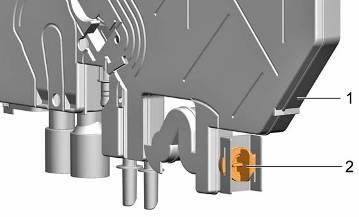
11 3.2 Door sensor Position of the door sensor Function of the door sensor Hall sensors (also known as Hall probes, after Edwin Hall) use the Hall effect to measure magnetic fields. A permanent magnet is inserted in the door lock. When the door is closed, the permanent magnet is positioned exactly over the Hall sensor. When the door is opened or closed, the strength of the magnetic field changes on the Hall sensor. The Hall sensor modifies its power input. The electronics detect whether the door is open or closed. If the power input is outside a defined range, this is detected by the electronics as a fault. The Hall sensor responds to the direction of the magnetic field. An incorrectly fitted permanent magnet or incorrectly polarised signal lines may result in wrong information being sent to the electronics. 1 Door sensor (Hall element) 2 Screw connection for door sensor The door sensor is situated in the centre at the top of the inner door.

12 3.3 Door lock/childproof lock Overall view of the mechanical door lock Function of the mechanical childproof lock (optional) The mechanical childproof lock prevents the door from opening. Activation: Pull lever outwards and push to the right. Deactivation: Push lever all the way in. 1 Door lock 3 Mechanical snap lock 2 Mechanical childproof lock (optional) 4 Permanent magnet The door lock is mechanical. A snap lock in the container frame engages in a recess in the door frame.
13 3.3.3 Electronic door lock (optional) The appliance can be secured to prevent programmes from being ended unintentionally (e.g. faulty operation by children). Deactivating button lock: Hold down button B for approx. 4 sec. until CL goes out. When the programme ends (on the digital display), the button lock is cancelled. If there is a power failure, the button lock is retained. Whenever a programme is started, the button lock must be re-activated Activating button lock: Start the required programme. Hold down button B for approx. 4 sec. until CL is indicated on the digital display. If any button is pressed while the programme is running, CL is displayed. The programme cannot be ended (reset).


14 3.4 Safety system Safety switch base pan Components in the safety system AquaStop / water inlet valve Overflow channel and drainage duct Safety switch base pan Intelligent electronics Overflow channel and drainage duct 1 Safety switch 2 Polystyrene float The safety switch is mechanically connected to the polystyrene float. 1 Overflow channel 2 Drainage duct Leakage water is conveyed out of the container via the overflow channel, through the drainage duct and into the base pan.
15 3.4.4 Function The safety system is based on an active system. The electronics continuously monitor the safety switch in the base pan. Even if the appliance is switched off. If water runs into the base pan, the safety switch is actuated. The appliance switches on. The electronics detect that the appliance was switched on via the safety system and immediately activates pump off. The AquaStop- / water inlet- valve is deactivated. Error code E:15 or a flashing tap LED indicates the error to the customer. The appliance can no longer be operated until The cause has been rectified and there is no longer any water in the base pan. The appliance has been isolated from the power supply. Auxiliary function with devices with AquaStop: If leakage water runs into the base pan via the rinsing tank and the overflow channel, a further overflow can be prevented by switching on the drainage pump. If the supply hose is defective, water runs directly into the base pan via the external hose (leakage water hose). The AquaStop valve is deactivated.

16 3.5 Aquastop valve Design The Aquastop valve is an electromechanical safety valve. The coarse and fine filters are located on the screw connection for the tap. Under the filters is the flow limiter. It limits the water flow to 2.5 litres. The Aquastop valve is enclosed by a housing. A leakage water hose (external hose > jacket around the supply hose) runs from the housing into the base pan. The leakage water hose contains the water supply hose and the electric control cable for the solenoid valve Function In the idle state the coil is de-energised and the seal interrupts the water flow by the effect of the spring which presses on the armature. If the Aquastop valve is connected to the water mains, the water pressure also acts from behind on the seal and supports the sealing. If leaks occur in the area of the valve or supply hose, these are conveyed into the base pan via the leakage water hose. A polystyrene float activates the electronic safety system via a microswitch. The coil of the AquaStop valve is deactivated by the electronics and interrupts the flow of water into the appliance. 1 Coarse filter 5 Seal 2 Fine filter 6 Control cable 3 Flow limiter 7 Leakage water hose 4 Coil 8 Pressure hose water supply

17 3.6 Water inlet When a rinse programme starts, the water inlet valve is actuated for 5 seconds. Water is expected to run in. Simultaneously pulses are expected from the impeller wheel counter on the electronics. If these remain off, an error code is displayed and the programme is not started. If pulses are received, the programme is started. When the programme starts, the electronic control opens the Aquastop/water inlet valve (filling valve). Water flows into the water inlet via the supply hose. The flow sensor and the free flow line are located in the supply channel of the water inlet. The water flows either into the granulate container (soften) or into the salt container (regenerate) via the regeneration valve in the water softening system. The outlet opening of the water softening system conveys the water back to the water inlet. The water flows directly into the rinsing tank via the outlet opening Bithermal connection (optional) Appliances with bithermal water connection have 2 supply hoses with AquaStop valve. The colour of the AquaStop valve identifies the difference between cold and hot water connections. The electronics control both valves separately. The appliance is supplied with either cold water or hot water. 1 Free flow line 7 Impeller wheel with flow sensor 2 Heat exchanger drainage valve 8 Supply hoses 3 Water softening system 9 AquaStop valve for hot water 4 Regeneration valve 10 AquaStop valve for cold water, optionally water inlet valve 5 Outlet opening 11 Heat exchanger water channel 6 Mixing piece

18 Devices with "heat exchanger Light" have no drainage valve. A sealing plug allows the water to flow directly into the water softener Heat exchangerr 2 Closing plug

19 3.7 Water inlet When a rinse programme starts, the water inlet valve is actuated for 5 seconds. Water is expected to run in. Simultaneously pulses are expected from the impeller wheel counter on the electronics. If these remain off, an error code is displayed and the programme is not started. If pulses are received, the programme is started. When the programme starts, the electronic control opens the Aquastop/water inlet valve (filling valve). Water flows into the water inlet via the supply hose. The flow sensor and the free flow line are located in the supply channel of the water inlet. The water flows either into the granulate container (soften) or into the salt container (regenerate) via the regeneration valve in the water softening system. The outlet opening of the water softening system conveys the water back to the water inlet. The water flows directly into the rinsing tank via the outlet opening. 1 Free flow line 6 Impeller wheel with flow sensor 2 Outlet opening 7 Expansion opening 3 Water softening system 8 Supply hose 4 Regeneration valve 9 Drainage hose ventilation valve 5 Water inlet valve
.")

20 3.8 Flow sensor Design of mechanical reed contact Function The flow sensor is attached in the water channel of the heat exchanger (impeller wheel counter). The impeller wheel rotates as water flows through the channel. A small permanent magnet attached to the impeller wheel switches both contacts of a magnetic switch (Reed switch). As a result, electrical pulses are generated. These pulses are counted by the electronics. The electronics use these pulses to calculate the amount of water which flows into the appliance. 1 PCB with reed contact switch 3 Contact tongues 2 Glass flask Reed contact switches switch or interrupt circuits. They are contact tongues fused in a glass flask in a vacuum or an inert gas and which simultaneously form the contact spring and the armature. The name derives from the reed of woodwind instruments as it resembles the oscillating contact tongues. The contact tongues are manufactured from a ferromagnetic material (e.g. soft iron) coated with a noble metal. The contacts are actuated by an externally acting magnetic field which is generated electrically by an approaching permanent magnet or in an appropriate magnetic coil. The magnetic field activates the two contact tongues which then close the circuit. As soon as the magnetic field declines or a certain force drops below a minimum value, the spring effect opens the contact again. Reed contact switches are very sensitive to mechanical effects such as distortion. 1 PCB with Reed contact switch 3 Impeller wheel 2 Permanent magnet


21 3.9 Expansion opening The heat exchanger is connected to the rinsing tank by the expansion opening. During the heating process the air in the rinsing tank expands. To prevent an overpressure and to ensure that the door is pressed on, air escapes via the expansion opening. If the door is opened while the washed utensils are warm, cold air flows into the appliance. If the door is closed, the air is heated by the warm washed utensils and expands. Overpressure occurs. This overpressure is released via the expansion opening onto the heat exchanger where it is dissipated via a small air hole. 1 Expansionsöffnung in water inlet system 1 Expansion opening in heat exchanger system


22 3.10 Free flow line If there is low pressure in the water line, water may flow out of the machine into the water supply system in the worst case scenario. Only air is drawn in through the opening in the flow line and the return flow of water is prevented Flow characteristics in the free flow line 1 Free flow line 3 Lug 2 Air equalisation opening The free flow line is a water bend with an opening. The curved shape accelerates the water which flows past the opening. As a result, almost no water can escape through the opening even at a low water pressure. If water nevertheless escapes, it flows into the appliance. In the case of appliances up to FD8903 the water runs into the tank via the expansion opening. With FD8904 a lug was inserted into the heat exchanger. Escaping water flows into the heat exchanger. This measure is stipulated by the deutsche Vereinigung des Gas- und Wasserfaches (DVGW). 1 Air equalisation opening

23 3.11 Water softening system Water softening The water softening system (ion exchanger) is a container which is filled with fine-grained synthetic resin granules. This synthetic resin replaces calcium and magnesium ions in the water with sodium ions which are on its surface. 1 Synthetic resin 1 Ion exchanger 5 Salt dispenser cover 2 Water inlet 6 Float element (optionally) 3 Water outlet 7 Salt dispenser 4 Regeneration valve 8 Low salt sensor The untreated water with its hardness constituents is conveyed via the synthetic resin. Calcium and magnesium are bonded to the surface of the exchange compound while sodium ions are released into the water. When all sodium ions have been replaced with ions of the hardness constituents, the capacity of the water softening system is exhausted and must be regenerated. Technical specifications: Capacity: Fine-grained salt Coarse-grained salt ca. 1.3 ca. 0.9 kg

24 Regeneration 1 Synthetic resin To make the ion exchanger functional again, a concentrated salt solution (sodium chloride) is conveyed from the salt dispenser by the water softener. Due to the large surplus the sodium ions from the salt solution displace the calcium and magnesium ions and attach themselves to the exchange compound. The ion exchanger is now loaded (regenerated) again and ready for use Regeneration cycle In dependence of the adjusted water hardness and the recognized quantity of water the regeneration cycle is steered by electronics.

25 3.12 Regeneration valve A 2-way valve (regeneration valve) is installed in the water softening system. This valve controls the water flow: Direct path into the ion exchanger Regenerate via the salt dispenser Water passages in the water softening system When the regeneration valve is in the idle state, the water is conveyed directly into the ion exchanger and softened Design 1 Valve with armature 3 Coil 2 Spring 1 Untreated water inlet regeneration valve 2 Untreated water outlet regeneration valve

26 1 Untreated water inlet regeneration valve with water inlet 2 Untreated water outlet regeneration valve with water inlet If the regeneration valve is actuated, the water flows into the salt dispenser and is enriched with salt. The water is conveyed back to the regeneration valve via the water channels of the water softening system. The brine solution flows into the ion exchanger. The granules are regenerated. The brine solution is conveyed into the rinsing tank via the heat exchanger and pumped out. 1 Untreated water inlet regeneration valve 3 Salt water inlet regeneration valve 2 Untreated water outlet regeneration valve 4 Salt water outlet regeneration valve
27 1 Untreated water inlet regeneration valve with water inlet 3 Salt water inlet regeneration valve with water inlet 2 Untreated water outlet regeneration valve with water inlet 4 Salt water outlet regeneration valve with water inlet
. 1 Photodiode 3 Transmitter LED 2 Regeneration salt The salt level is detected via a light barrier.")

28 3.13 Low salt detection 1 Water softening system 2 PCB with light barrier The PCB for the low salt indicator is attached with clips to the right side of the water softening system (front side of appliance). 1 Photodiode 3 Transmitter LED 2 Regeneration salt The salt level is detected via a light barrier. If the regeneration salt runs low, the line in the light barrier is freed and the electronics detect Add salt. If the low salt indicator appears, there is still so much salt in the appliance that some more regeneration processes may occur. According to this principle it is not necessary to fill the salt dispenser with water when switching on the appliance for the first time. Filling with salt tablets is system-dependently not recognized.


29 3.14 Filter system Fine filter cylinder Conventional fine filter systems are based on a round cylinder shape. If the cylinder is rolled out, the filter surface can be seen. 1 Fine filter cylinder rolled up 2 Fine filter cylinder rolled out The new fine filter system is based on a corrugated fine filter cylinder. If it is rolled out and smoothed, a 1.5x filter surface can be seen. 1 Fine filter cylinder 3 Coarse filter 2 Surface filter, alternatively stainless steel or plasic The 3-stage filter system is intended to prevent particles from getting into the rinsing circuit and impairing the pumping or spraying system. 1 Corrugated fine filter cylinder, rolled up 3 Fine filter cylinder, rolled out 2 Fine filter cylinder, rolled out
 2 Connection for lower spray arm 6 Water switch motor with pulse generator (optionally) 3 Supply pipe connection for roof sprinkler (optionally) 7 Heating pump 4 Supply pipe connection")

30 3.15 Pump sump The pump sump is illustrated here with all mounted parts. 1 Aqua sensor (optionally) 3 Suction cap 2 Drain pump cover Covers in the pump sump 1 Drain pump 5 Water switch (optionally) 2 Connection for lower spray arm 6 Water switch motor with pulse generator (optionally) 3 Supply pipe connection for roof sprinkler (optionally) 7 Heating pump 4 Supply pipe connection for upper spray arm The suction cap ensures that the pump has an optimized suction performance and flow performance. No air or dirt is drawn in. This cap should not be removed by the customer. The cover of the drain pump is used to channel the water. Without the cover the drain pump cannot build up any pressure. Customers may remove the drain pump cover for cleaning purposes. If the cover is not correctly attached, the water cannot be pumped out.

31 3.16 Water switch The water switch controls the water passage of the 3 spray levels and the filling of the optional water storage tank. It consists of a drive motor with cam plate, pulse generator and the locking disc. When the appliance is switched on, the motor is actuated via a triac. The cam plate is attached to the motor axle. The cam plate actuates a switch (pulse generator) which transmits pulses of different length and intervals to the electronics. If the electronics detect the standard setting, the water switch is initialised. The locking disc is rotated depending on the actuation. In doing so, holes of varying size release the water passage on the particular spray level or the connection of the hose to the optional water storage tank. The arrangement of the openings in the locking plate allows several levels to be actuated simultaneously or alternately. 1 Locking disc 5 Cog with cam plate 2 Seal 6 Cog 3 Pulse generator (switch) 7 Connection water storage tank (optionally) 4 Drive motor
32 3.17 Heating pump Design of the heating pump: Overall view of the heating pump The heating pump contains the heater, temperature sensors and circulation pump in one housing. Pump housing with internal temperature 1 shield made of metal 2 Heating tube with NTCs 3 BLDC motor 1 Pressure connection 4 Heater connection 2 Circulation pump motor 5 Housing cover 3 Circulation pump motor connection 6 Intake connection

33 Function of the circulation pump The water is drawn in via the intake connection. The guide wheel guides the water evenly along the heating tube. The water is pumped to the water points via the pressure connection. While water is being circulated, the BLDC motor (Brushless DC Motor) signals different states to the power electronics via the current consumption of the individual windings: No water, too little water, snorkels adequate water level, (true running) pump blockage. 1 Pressure connection 5 Guide wheel 2 Heating tube with NTCs 6 Intake connection 3 BLDC motor 7 Pump housing with intake and pressure connections 4 Pump wheel Safety-relevant states, such as Heating without water or Water temperature too high, are detected and evaluated for the heating operation. If the pump is blocked, this is detected by the electronics. By several approach attempts, the pump try to loosen the blockage. If this is not successful, the running programme ends. A corresponding error code is saved in the error memory.

34 Design of the heater If the appliance is connected to a hot water connection or solar equipment, the heater is switched off at a supply water temperature of > 70 C. 1 NTCs 2 Heating paths The heating paths are applied to a specially coated metal tube. The connections and two NTCs are integrated in the heating paths. The heating tube cannot be replaced separately Function of the heater / NTCs The water temperature is determined via the NTCs. In heating mode the electronics detect the temperature increase which occurs.

35 3.18 Drain pump If there is too little water in the pump area, pumping is stopped. If there is no cap in the pump sump, water pressure cannot build up. An error code is saved in the electronics. If the pump is blocked, this is detected by the electronics. By brief intermittent pumping, the pump attempts to loosen the blockage. If drainage is disrupted by a blockage or a kink in the drainage hose, pumping is stopped. An error code is saved in the electronics. Detection occurs via the current input of the pump during idling and the different load states. 1 Catch mechanism 3 Impeller wheel 2 Seal 4 Cable holder The water is drawn in via the water outlet opening of the pump sump. The impeller wheel pumps the water through the non-return valve into the drainage hose. While water is being pumped out, the BLDC motor (Brushless DC Motor) signals different states to the power electronics via the current consumption of the individual windings: No water, (idling) No pressure build-up (missing service flap) Pump blockage Blocked or kinked drainage

36 3.19 Aqua sensor (optional) In each programme sequence in which the Aqua sensor is active the Aqua sensor is calbrated. If calibration is defective, an error is written into the error memory of the power electronics. The measured value is set to turbid and a maximum programme sequence occurs No Aqua sensor installed There are appliances which are supplied without Aqua sensors. Nevertheless, the electronics check the Aqua sensor and save an error message. 1 Seal 3 PCB with light barrier 2 Housing A infrared diode and a phototransistor are located opposite each other in a U-shaped translucent housing on a board. The infrared diode transmits infrared light through the detergent solution flowing between the U-shaped housing. Depending on the turbidity, the light-sensitive base of the phototransistor becomes conductive. The measurement is analysed in turbidity ranges. The values are saved in the electronics. The Aqua sensor is active in the prerinse, the wash and at the end of the wash. The result of the Aqua sensor analysis influences the sequence of the rinse programmes. A wide range of programme structures is possible in the automatic programme.
37 3.20 Spray system The spray system consists of 3 spraying levels: the lower and upper spray arms and an optional roof shower head. Water is supplied to the upper spray arm and the roof shower head via the supply pipe attached to the inside of the tank rear panel. This pipe is connected to the pump sump by a direct plug-and-socket connection. The supply pipe has 2 separate water channels. As a result, the upper spray arm and the optional roof shower head can be actuated separately. The upper spray arm is attached by its inlet pipe directly to the top basket. The supply pipe is connected by a coupling. Optionally, the height can be adjusted by max. 3 levels (Rackmatik). The lower spray arm is connected by its bearings directly to the pump sump. It has a nozzle on the underside to clean the surface filter and to rinse dirt into the filter system. Appliances without a water switch do not have the roof shower head. Both spray arms can only be operated simultaneously. 1 Roof shower/roof spinner (optional) 5 Heating pump 2 Coupling for upper spray arm 6 Pump sump 3 Supply pipe 7 Lower spray arm 4 Water switch (optional) 8 Upper spray arm
.")
38 3.21 Basket system Cutlery drawer - option The basket system consists of 2 3 levels. The baskets differ in features and colour depending on appliance class. The table indicates the differences in features (date ). Top basket Vario VarioFlex VarioFlexPlus Ball ends Split additional cup racks, hinged Folding spikes optional Optimised glass holder Height-adjustable basket (3x Rackmatic) optional Basket handle Dosing assistant Bottom basket Ball ends Split additional cup racks, hinged optional Holder for long-stemmed glasses High basket back Basket handle 1 Pull-out plate 2 Basket handle The cutlery drawer is attached at the very top of the rinsing tank. It is used as a holder for cutlery, other cooking accessories and also espresso cups. The utensils are washed primarily by the roof sprinkler. See Spray system.


39 Loading example: VarioDrawer Plus optionally from 10/ Lowerable elements 3 Folding spikes 2 Lowering mechanism 4 Opening Starting from 10/2011 a VarioDrawer comes to the employment. This contains 2 rows flip tiens and lowerable files in the external areas, separately for right and left.


40 Representation of mobile elements and loading example: Top basket 1 Knife shelf 4 Rackmatik plate 2 Folding spikes 5 Basket handle 3 Split, hinged additional cup racks The extendable top basket is loaded with smaller plates, glasses and cups. The utensils are cleaned by a spray arm under the top basket. When the top basket is pushed in, it docks with the supply pipe at the rear to make the water connection (see Spray system).

41 Representation of mobile elements: Loading example:
 3 Split, hinged additional cup racks 6")

42 Bottom basket 1 Ball ends 4 Folding spikes 2 Holder for long-stemmed glasses 5 Cutlery basket (optionally) 3 Split, hinged additional cup racks 6 Basket handle The bottom basket is moved out of the appliance on rollers. The fixed lower spray arm cleans the utensils in the bottom basket (see Spray system).
43 Representation of mobile elements: Loading example:

44 Loading example:
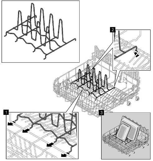
45 Ball ends Ball ends are small balls on the tips of the folding spikes. If glasses or plates are placed on standard spikes, streaks may form in the area where the utensil touches the spike. The ball ends generate a minimum gap. As a result, utensils can be washed and dried without streaks Holder for long-stemmed glasses A folding bracket on the back of the bottom basket can be folded forwards so that long-stemmed glasses can also be arranged on a 2nd row Etagere An etagere is an additional hinged shelf in the baskets. As it is attached in the top of the basket, this produces another level (etage). There is space on this level for mocha cups or small objects Folding spikes These spikes can be folded down so that utensils can be arranged more flexibly. The spikes can be folded down on several levels or only on one level Rackmatik The height adjustment for the top basket is called Rackmatik. The adjustment can be on several levels (3 levels). The supply pipe has connections for one 3-level Rackmatik. The top basket can also be tilted to the right or left. The metal holders of the Rackmatik are pressed mechanically into the top basket. If the holders are bent open, the surface of the top basket may be damaged.

46 3.22 Dosing assistant The tab drops into the tray. The spray arm in the top basket sprays the tray from below to dissolve the tab. The bottom basket can no longer be pulled out over the dispenser. Food remnants can no longer drop into the dosage chamber and block it. 1 Top basket 3 Dispenser 2 Handle cover 4 Spray arm top basket The dosing assistant is an interaction between the arrangement of the dispenser and the handle cover in the top basket. The dispenser is situated in the middle of the door on the upper side of the door. In the top basket is the handle cover or tab drawer.

47 3.23 Water outlet If the drain pump is actuated for draining, the water is pumped to the heat exchanger. The water flows to the drainage hose via the heat exchanger and out of the appliance. A non-return valve is installed in the hose connection of the pump sump. This prevents the return of waste water into the pump sump. 1 Drain pump 5 Air duct 2 Inner drainage hose 6 Float chamber with float 3 Input water outlet 7 Drainage hose 4 Output water outlet

48 3.24 Non-return valve The non-return valve prevents water from running back out of the drainage area of the appliance. This prevents dirt residue, dirty water or detergent residue from flowing back into the rinsing circuit. 1 Pump sump 3 Sealing lip 2 Non-return valve

49 3.25 Ventilation sequence During pumping, water is pumped to the drainage hose via the drainage channel of the heat exchanger / water inlet. A continuous water flow occurs. If the drainage is lower than the appliance, the water flows out of the appliance by suction effect even if the drain pump is no longer actuated. In the float chamber there is so much water that the float floats and the ventilation opening closes. The ventilation opening is released by the float as soon as the water flow in the water outlet decreases. The appliance cannot be drained while the liquor pump is deactivated as air can flow in via the ventilation opening. If the drainage hose is defective (blockage, kink), pressure builds up. Electronics detects the blockage over by drain pump An error code is saved in the failure memory. 1 Input water outlet 4 Float chamber 2 Output water outlet 5 Float 3 Air duct 6 Ventilation opening


50 3.26 Dispenser When the dispenser is filled with rinse aid, the cover is closed. It stays closed until it is manually opened again. The dosing chamber for detergent is opened mechanically in the appropriate washing section. Powdered detergent flows into the rinsing tank. Tabs drop into the handle cover (dosing assistant). 1 Coil 3 Dosing pump 2 Anchor with switching mechanism 4 Low rinse aid sensor 1 Rinse aid dispenser cover with seal 5 Detergent dispenser cover 2 Rinse aid outlet opening 6 Detergent dosing chamber 3 Rinse aid filler opening 7 Plastic bars 4 Detergent flap locking button

51 Function The actuator mechanism for the detergent cover is actuated via a coil. The coil is actuated via pulses from the power electronics. When the coil is switched on, the anchor is moved to the left. The anchor is connected by a plastic lever to the release lever of the detergent cover. When the actuation lever is turned, the detergent cover is released and opens. There is a switching mechanism between the coil anchor and the rinse-aid valve. The switching mechanism prevents rinse aid from being metered when the coil is initially actuated. When the detergent cover is opened, the mechanism switches similar to a ballpoint mechanism. The detergent cover is no longer actuated, but the dosing pump for rinse aid. With each pulse 1 ml of rinse aid is dispensed. The setting stage for the rinse aid corresponds to the pulses and the dispensed amount. To ensure that the rinse aid container drains, there is a scoop chamber. This is always filled when the appliance door is fully opened. The rinse aid flows out of this scoop chamber into the appliance. If the door is not fully opened, rinse aid may not flow into the appliance because the scoop chamber was not filled. 1 Coil 3 Anchor with switching mechanism 2 Release lever 4 Dosing pump A ventilation system is used to equalise the pressure in the dispenser. If the appliance door is opened, the actuating mechanism is reset. This causes the detergent cover to open first the next time the coil is actuated. If there is humidity left in the detergent dispenser and a detergent tablet is inserted, the tablet begins to dissolve slowly. 2 plastic bars in the dispenser prevent the detergent from sticking to the housing.

52 3.27 Low rinse-aid sensor The optical low rinse-aid sensor consists of a transmitter diode and a photo transistor. A light beam is transmitted from the transmitter diode to the receiver diode via a prism. If the dispenser is full, the light beam in the prism is scattered. The received signal is weaker than the transmitted one. 1 Receiver diode 3 Transmitter diode 2 Prism 1 Receiver diode 3 Transmitter diode 2 Prism If the dispenser is empty, the light beam in the prism is reflected. The received signal is the same as the transmitted signal. The received signal is analysed and displayed via the power electronics.

53 3.28 Door springs Construction-partly the following spring system can be also used: The door springs are situated on the right and left under the base pan. The tensile force is transferred to the door hinge with a tension cord via a deflection lever. The tensile force of the door springs cannot be adjusted. The installed spring and the cable system automatically adjust themselves to the door weight. Springs with different tensile forces are available. They are marked by coloured points. The allocation to the released furniture fronts is shown in a table in the chapter replacing the springs. 1 Holder for tensioning cable 3 Tension cord 2 Deflection lever 4 Door spring 1 Door spring 3 Deflection lever 2 Tension cord 4 Holder for tensioning cable
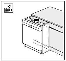
54 3.29 Variable hinge Description The variable hinge enables fully integrated dishwashers to be installed in kitchens with a low base. The device moves the decor front upwards when the door is opened. As a result, the overhang at the bottom is smaller and passes over the base. The gap between the base and furniture door can be reduced. If appliances are installed higher, the visual appearance is significantly improved.


55 3.30 Foot adjustment Depending on the design, the appliances feature 3 or 4 appliance feet. The adjustable heights vary. Illustration 2: Built-in & built-under appliance Illustration 1: Free-standing appliance

56 3.31 Customer settings Requirement: Appliance is switched on Button layout Selection of the customer settings Simultaneously press button A and the Start button Selection ranges To select the range, press button A. To change the value, press button C Possible settings Range Display Selection Warm water connection A:00 A:01 Switch on and off, factory setting: A:00 - Off Hardness range H:00 H:07 8 ranges, On - Off factory setting: H:04 Intensive drying d:00 d:01 Switch on and off, factory setting: d:00 - Off Rinse aid r:00 r:06 6 ranges, On - Off factory setting: r:05 Buzzer B:00 b:03 3 ranges, off factory setting: b:02 Language selection L:01 L:19 19 languages factory setting: L:01, German Auto Power OFF P:00 P-02 P:00 Off, Emotion light on P:01 Off after 1 minute, Emotion light off P:02 Off after 120 minutes, Emotion light off Factory setting: P:01 EmotionLight E:00 E:01 On Off factory setting: E:01 On On-board computer C:00 C:01 On Off factory setting: C:01 On Info Light I:00 I:01 On Off factory setting: I:01 On Saving the setting Press Start button Partly optional functions

57 3.32 Emotion light (optionally) Emotion light is an internal light. 1 LEDs 3 Cap 2 Ribbon cable If the Emotion Light function is activated in the appliance menu, 2 LEDs light up when the door is opened. The interior light (Emotion Light) comes on when the door is opened irrespective of whether the ON/OFF switch is switched on or off. When the door is closed the light is off. If the door is open for longer than 60 min., the light switches off automatically. The interior light is lit only when the set value P:00 is selected.

58 3.33 Info light (optional) The user is provided with additional information by fully integratable models with a programme status display visible from the outside (info light). The info light consists of an LED and a fibre-optic cable. The light is bundled via the fibre-optic cable and is projected as a red light spot on the subsurface in front of the dishwasher while the programme is running. The info light is attached between the inner and the outer door on the right hinge plate and is actuated by the module. A LED C Light spot B Fibre-optic cable D Subsurface


59 3.34 TimeLight (optional) TimeLight projects user information about the operating state of the appliance for fully integrated models onto the floor in front of the appliance. Function: An LED radiates light which hits a condenser lens. The function of this lens is to collimate the incoming light to ensure that the LCD panel is evenly illuminated. The LCD panel has a resolution of 34 x 34 pixels. The graphic information is deflected via mirrors. The TimeLight projection module is available only as a complete module. 1 LED 4 Mirror 2 Condenser lens 5 Projection lens 3 LCD panel 6 Housing

60 Projection process: 34 x 34 pixel 1 Projection module in the base plate 4 Projection surface 2 Deflection mirror in the base plate 5 Base panel 3 Outer door

61 3.35 Power module Position of the components NOTE Electrostatic sensitive devices Components will be destroyed if touched Before carrying out any work, apply protective system to components susceptible to electrical discharge. Observe measures to protect the components susceptible to electrical discharge. 1 TH401 = water points 9 K304 = inrush current limiter 2 TH403 = reserve Optionally: Valve water storage tank / Aqua stop valve warm water 10 K100 = bistable relay, security system connection 3 TH404 = heat exchangerdrainage valve (optionally) 11 K303 = heater 4 TH405 = regeneration valve 12 K305 = heater zeolith 5 TH402 = filling valve 13 K301 = relay security 6 K201 = reversal relay circulation pump / drain pump 14 Varistor, overvoltage protection 7 K202 = reversal relay circulation pump / drain pump 15 8 T412 = coil - dispenser 16
62 3.36 Power cords country versions Power cord The power cord has a cold appliance system connection and is enclosed with the appliance. When the appliance is switched on for the first time, the cable must be connected to the back of the appliance Country versions Different power cords are offered as optional accessories via Sales. WARNING Incorrect connected loads! Destruction of the appliance If a power cord is replaced with a power cord with a different plug, check the connected loads of the appliance with the supply voltages and frequencies of the particular country Extension leads 3 metre extension cables are available from customer service. These are currently released by PG. Material number EU version: Material number GB version:
63 3.37 D-bus2 / appliance software DANGER Exposed live parts Danger to life caused by electric shock! Disconnect the appliance from the power supply. Do not touch housing, frame or components. Use residual-current-operated circuit-breaker if tests have to be conducted while the appliance is live. Ensure that the resistance of the protective conductor does not exceed the standardised values. The software can be manually imported (flashed). A connection with the D-bus2 is established via the UDA. CAUTION Voltage peaks with the release/connecting the plug contacts Destruction of the control module or the piezo power supply unit (optional) by net potential on the ground wire of the bus system. Disconnect the appliance from the power line before release/connecting plug connectors. Communication between the electronically components is via a D-bus2. The D-bus2 consists of a 3-pole line system. The 3 lines are connected as follows: 13,5 V d.c. via GND GND (possibly power potential) Data line

64 3.38 Weight Free-standing appliances have a weight in the rear area of the base pan. This prevents the appliance from tipping over if the door is opened and the baskets pulled out. There are 2 different concrete weights: Appliances with cutlery drawer: 6.5 kg Appliances without cutlery drawer: 5.5 kg Appliances with Zeolith additional heating system: 2.4 Kg 1 Counterweight
65 4 DIAGNOSTICS 4.1 Malfunctions Fault Cause Fault correction Tablet does not dissolve. Spray arm stiff, sticking, touches container rear side. Check function of the upper spray arm (Use of glass door, material number: 81cm: ; 86 cm: ). Tablet does not fall into the basket handle on 86 cm appliances. Program Stops; Program cannot be started Program suspends Tolerances Door lock not correctly closed, there door lock engaged. Closing force too highly. Insert tablet chute (material number ) into top basket. Close door firmly thereby the door lock works normally again. Closing force reduction by exchange of upper piping
66 4.2 Result faults Fault Cause Fault correction Poor rinsing result. Tablet does not fall into the basket handle on 86 cm appliances. Spray arm stiff, sticking. Unsatisfactory washing result in the bottom basket of zeolite appliances. non-return valve defectively/blocked/clogs Dispenser does not open, because Tab blocks the dispenser cover, Tab upright inserted remainders in the dispenser Missing cover of water softener in AU models Lower spray arm blocked on the blow-out cap of the zeolite container. Insert tablet chute (material number ) into top basket. Check that the spray arms function (Use of glass door, material number: 81 cm: ; 86 cm: ) -> replace spray arm. Examine, release it Advise customer, insert Tab correctly Spraying arm blocked, dishes, smell donors in grip cap - > advise customer AU models are partially coated with a "dummy" - equipped softener. Screw on lid. Check that the cap is secure. It must be locked all the way. On account of an increased number of enquiries concerning the washing result of the series GV640, the possible reasons for the poor washing result complaint and information on possible remedies are listed below. Faults which can be clearly attributed to operating faults, as well as inadequate maintenance, must not be claimed under the warranty. Appropriate use and maintenance instructions can be found in the indicated chapters in the Instructions for use and Quick reference guide. Does the problem persist, sporadically or at specific intervals? Were different programmes or detergents used or tested? Has the problem been occurring since a specific time (new utensils, change in detergent,...)? Are only utensils in certain areas (only top/bottom basket, only corner areas,...) affected? The performance test must be conducted in the customer service test programme using the glass door. From experience it is important to scrutinise not only the fault description but also the circumstances of the occurrence on acceptance of the order and to mention these in the order.
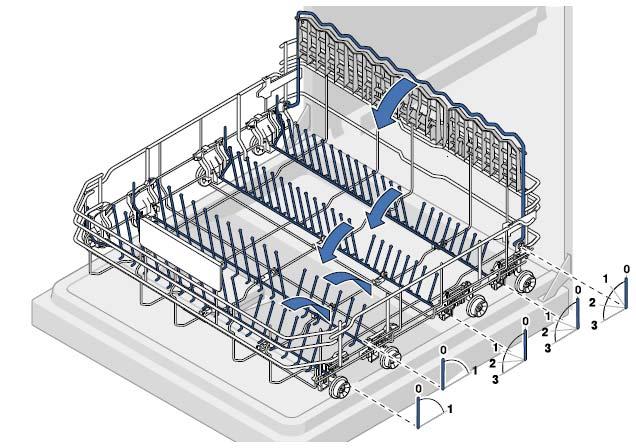
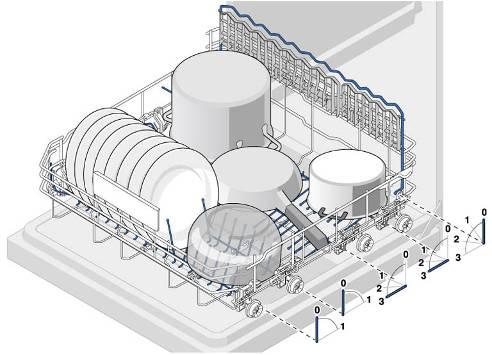
67 1. Residue on the utensils Fault description Cause Remedial action Food remnants or sandy residue Utensils placed too closely together, overfilled. Observe correct arrangement of utensils (arrange according to Fig. 1, Fig. 2 and Fig. 3). Spray arm blocked by utensils or cutlery. Utensils precleaned too intensely; sensors therefore decide on weak programme sequence. Stubborn soiling cannot be completely removed. Filter not locked in the pump sump or incorrectly inserted. Spray arm nozzles, roof shower head blocked (e.g. lemon pips, etc.). Coarse, micro and fine filter dirty. Spray arm bearings do not move smoothly (dirt around the bearings). Spray arm or supply pipe deformed -> spray arm strikes the basket or the docking site. Waste-water pump blocked. Dirty water runs back into the appliance -> re-soiling. Arrange utensils so that spray arm can rotate without obstruction. (arrange according to Fig. 2 and Fig. 3); see Utensils Do not prerinse utensils; remove only large food remnants. Programme recommendation Eco 50. Insert and lock filter correctly; see Maintenance and care Clean nozzles and roof shower head and insert/lock filter correctly; see Maintenance and care Clean filters; see Maintenance and care Clean parts, show customer how to insert filter correctly. Replace spray arm. Check waste-water pump; see Eliminating faults yourself Check draining, check non-return valve for leaks. Top basket on right and left not set to same height. Utensils unfavourably arranged (very large utensils e.g. pans in the bottom basket), avoid contact points, prong rows bent. Tall narrow receptacles are not rinsed adequately in the corner area. Set top basket to same height using side levers. Arrange utensils so that spray jets can reach surface of utensils (arrange according to Fig. 2 and Fig. 3). Do not place tall narrow receptacles too obliquely or in the corner area (arrange according to Fig. 2 and Fig. 3).
68 Fault description Cause Remedial action Detergent residue Water stains on plastic parts Detergent dispenser cover blocked by utensils (cover does not open fully). Detergent dispenser cover is blocked by the tablet. Tablets used in the Quick or Short programme. -> Dissolving time of the detergent is not reached in the selected short programme. Detergent residue in final rinse; detergent-solution carry-over. Detergent very lumpy, washing effect and dissolving performance are reduced after a prolonged storage time. Droplet formation on plastic surface is physically unavoidable. Plastics do not store heat. After drying, substances in water are visible. Check detergent dispenser function, detergent cover must not be obstructed by utensils. Do not place any utensils or aroma dispensers in the dosing assistant. Advise customer, insert tablet correctly (flat, not upright). Advise customer, dissolving time of the tablets too long. Use detergent powder or select a more intensive programme. Check draining, check non-return valve for leaks. Advise the customer. Always insert tablet just before the programme starts. Use more intensive programme (more water changes); see Programme overview Note inclination when arranging utensils. Use rinse aid, if required increase see Rinse aid. If required, increase softening setting; see Water softening system Water residues Wrong loading Correct sequence for eliminating consider Fig 4 Coloured (yellow, orange, brown), easily removable, soapy residue in the interior Soap-like layering of ingredients of food residue and lime. Because of tolerances for combined detergents (3 in 1 or higher) can make it necessary to use the water softener already at a water hardness of 16 dh. Advise customer and contrary to the indication of the detergent manufacturer activate the water softener additionally Residue in the pull-out rails Detergent and food remnants are deposited due to design. Clean by hand, - for the upper basket use the modified pull-out rails with mat.no for the cutlery drawer use mat.no
69 2. Coatings: Fault description Cause Remedial action Wipe-clean or water-soluble coatings in the container or on the door Detergent substances are deposited. These coatings cannot usually be removed with chemicals (appliance cleaner,...). Water softening system set marginally; fault description occurs cyclically White coating on container floor. Change detergent brand. Clean appliance mechanically. Increase softening setting and change detergent if required. Regeneration salt on the utensils: Leaking salt dispenser cover. Leaking regeneration valve. Detergent residue in the final rinse; detergent-solution carry-over. Wrong programme selected. (Quick programme selected) Initial clouding of glass -> can only apparently be wiped off. Advise customer, eliminate leak. Check regeneration valve or valve seat (customer service programme). Check detergent dispenser function, detergent cover must not be obstructed by utensils; Select suitable programme. see Programme overview Damage to utensils
70 Fault description Cause Remedial action White, stubborn coatings; limescale on the utensils, container or door Detergent substances are deposited. These coatings cannot usually be removed with chemicals (appliance cleaner,..). Hardness range incorrectly set or untreated water hardness greater than 50 dh. Water softening system is not being regenerated. Change detergent brand. Clean appliance mechanically. Check residual hardness in the cleaning and final rinse cycles and set water softening system according to instructions for use. Top up salt; see Water softening system Check function of the regeneration valve in the customer service programme. Starch deposits on the utensils Tea or lipstick residue on the utensils Coloured (blue, yellow, brown), difficult to remove to nonremovable coatings in the container or on the door 3in1 detergent or bio/eco detergent not effective enough. Set water softening system according to instructions for use; use separate agents (proprietary detergent, salt, rinse aid); see Water softening system Underdosage of detergent (verification with Minilabor mat. no ). Advise customer; increase detergent dosage, change detergent. Wrong programme selection (programme too weak) selected. Too low rinsing temperature. Too little detergent. Utensils precleaned too intensely; sensors therefore decide on weak programme sequence. Stubborn soiling cannot be completely removed. Unsuitable detergent. Film formation consisting of ingredients from vegetables (e.g. cabbage, celery, potatoes, noodles,..) or the tap water (e.g. manganese). Film formation caused by metallic components. Known for silver or aluminium utensils. Advise customer; correct programme selection; see Programme overview Select programme with higher washing temperature; see Eliminating faults yourself Use suitable detergent at correct dosage. Do not prerinse utensils; remove only large food remnants. Programme recommendation Eco 50. Change detergent. Can be partly removed with machine cleaner (mat. no ) or mechanical cleaning. Coatings are harmless. Can be partly removed with machine cleaner (mat. no ) or mechanical cleaning.
71 3. Discolouration: Fault description Cause Remedial action Coloured (blue, yellow, brown), shimmering, difficult to remove to non-removable discolouration in the container or on the door Film formation consisting of ingredients from vegetables (e.g. cabbage, celery, potatoes, noodles,..) or the tap water (e.g. manganese). Film formation caused by metallic components. Known for silver or aluminium utensils. Can be partly removed with machine cleaner (mat. no ) or mechanical cleaning. Mechanical removal with Vienna chalk (mat. no ) usually possible. Coatings are harmless. Can be partly removed with machine cleaner (mat. no ) or mechanical cleaning. Discoloration on plastic parts Wash programme too weak. Select different wash programme; see Eliminating faults yourself Too low rinsing temperature. Select programme with higher wash temperature. Utensils precleaned too intensely; sensors therefore decide on weak programme sequence. Stubborn soiling cannot be completely removed. Do not prerinse utensils; remove only large food remnants. Programme recommendation Eco Streaking on glasses and cutlery Removable streaking on glasses and cutlery Glasses with metallic appearance Too much rinse-aid. Set rinse-aid amount to lower level; see Rinse aid No rinse aid added or setting too low. Add rinse aid and check dosage (recommendation level 4-5); see Rinse aid Non-return valve leaking. Detergent residue in the final rinse. Detergent dispenser cover blocked by utensils (cover does not open fully). Utensils precleaned too intensely; sensors therefore decide on weak programme sequence. Stubborn soiling cannot be completely removed. Check non-return valve for leaks. Check detergent dispenser function, detergent cover must not be obstructed by utensils. Do not place any utensils or aroma dispensers in the dosing assistant. Do not prerinse utensils; remove only large food remnants. Programme recommendation Eco 50.
72 5. Damage to utensils/water-insoluble residue Fault description Cause Remedial action Initial or existing irreversible clouding of glass Glasses not adequately dishwasher-proof (glasses are usually only suitable for dishwasher). Advise the customer. Reduce main causes of glass corrosion: Use dishwasher-proof glasses. Avoid long steam phase (standing time after wash cycle ends). Use programme at lower temperature. Set water softening system according to the water hardness (if required one level lower); see Water softening system Use detergent with glass protection component.
73 6. Rust Fault description Cause Remedial action Rust marks on cutlery Stains on the cutlery Cutlery not adequate corrosion-resistant. Knife blades are frequently more severely affected. Cutlery infected by extraneous rust from rusting parts (metal lid, damaged utensils basket, etc.). Salt content in the rinsing water too high, as salt dispenser lock not fastened firmly or salt was spilled while being refilled. Large contact surfaces between cutlery and too little inclination of e.g. spoons prevent the water from draining and cause staining. Coarse, micro and fine filter dirty. No rinse aid added or setting too low. (Combination detergents have a lower final rinsing effect than separate rinse aids). Hardness range incorrectly set or untreated water hardness greater than 50 dh. Minor discolouration or residue at the contact points are physically induced and unavoidable. Use corrosion-resistant cutlery. Do not wash rusting parts. Fasten salt dispenser lock firmly or remove spilled salt (by prerinsing cycle). Arrange cutlery so that there are as few contact surfaces as possible. (Arrange according to Fig. 1 and Fig. 2). Clean filters; see Maintenance and care Add rinse aid and check dosage (recommendation level 4 5); see Rinse aid Check residual hardness in the cleaning and final rinse cycles and set water softening system according to instructions for use. Top up salt; see Water softening system Minimisation possible by means of the points stated in this section.


74 Figures: Fig 1 A Arrange knives and other sharp-edged or pointed cutlery with the blades face down to prevent accidental injury. B Do not place items of cutlery on top of each other. Correct arrangement certainly aids stain-free cutlery. C Arrange spoons and ladles at an incline. This will prevent accumulation of water and stains. Fig 2 A Do not place utensils on top of each other. Otherwise, parts on top will not be sprayed from below with adequate water. B Avoid large contact points between utensils. This prevents food remnants and stains on the utensils. C Do not overload cutlery basket. Minimise contact points between items of cutlery. This ensures stain-free cutlery. D Arrange hollow receptacles in such a way that water cannot collect inside. Do not let utensils project through the utensils basket. This ensures that the spray arm is not blocked.

 project through the utensils basket.")
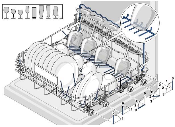
75 Fig 3 A Arrange hollow receptacles in such a way that water cannot collect inside. B Do not place utensils on top of each other. Otherwise, parts on top will not be sprayed from below with adequate water. C Arrange cups and bowls at an incline. This prevents water from accumulating in their base area. D Do not place hollow receptacles too obliquely and do not place directly in the corner area. This ensures that they can be flushed out properly. E If appliances feature a tablet collecting tray, do not load it with utensils or aroma dispensers, otherwise the detergent dispenser will be obstructed. Do not let utensils (e.g. small ladles) project through the utensils basket. This ensures that the spray arm is not blocked.
76 Fig 4 Eliminate the baskets in the following order: 1 Lower basket. 2 Upper basket 3 - cutlery drawer (optionally).
77 4.3 Electrical faults Fault Cause Fault correction Low salt indicator is Salt tablets used. Advise customer: do not use salt tablets. constantly lit. 4.4 Mechanical faults Fehler Ursache Fehlerbehebung Door cannot be closed. Catch locked by the door lock. Close door firmly until the lock is functioning normally again. Cutlery drawer clamps FD 9006 to FD 9010 incl. Change the pull out rails of the cutlery drawer (Mat.Nr ).

78 4.5 Leaks Fault Cause Fault correction Leakage under heat exchanger Expansion opening does not bolt correctly. Consider the sequence when assembling the heat exchanger: See also to chapter replacing heat exchanger Error E:15 generated from leakage under water softener in FD 9110 ~ Minimal leakage in the water softener can generate error E:15 after many wash cycles. Change water softener complete: - See also to chapter replacing water softener system 4.6 Dishwasher functions / Software Fault Cause Fault correction After switching on the dish With KI 59 a new software is implemented. The default Advise customer: EU-directive (EU1275 / in 2008, washer, it begins with ECO start program is always ECO, no matter which programme conformance index 011) specify this programming. 50 programme. was chosen in the last washing cycle.
79 5 TEST AND REPAIR 5.1 Testing water hardness in the appliance Some faults require that the water hardness is determined in the appliance. Check the following beforehand: Is regeneration salt used? Has regeneration salt been added? Is the water softening system switched on? Has the correct degree of hardness been switched on? Does the customer use tablets (which ones)? Testing while the water softening system is active Start test programme and let the appliance fill up to the first pause, checking visually. Determine water hardness in the appliance using the water hardness test. Approx. 5 to 7 dh should be measured provided the water softening system is intact and regeneration cycles have been set correctly. If the value is significantly higher, test the water softening system Operating the appliance with the water softening system switched off If the water softening system is deactivated, detergent tablets with salt replacement substances should be used. Note what is written on the packaging. The chemical components of multifunction tablets bind the limescale in the water to themselves. These are effective up to approx. 21 dh. Note the product description of the manufacturer. Test the water hardness of the supply water Advising the customer If the water hardness is above the range within which the utilised tablets have a softening effect, advise the customer to use the regeneration system with regeneration salt. If the customer uses tablets without salt replacement substances, suggest that special salt is used. The appliance must be set correctly.

80 5.1.4 Checking water supply The electronics check the water level in the appliance during the prerinse and wash cycles via the heating pump (uniformity check). If required, the water is topped up. The filling capacity for the clear rinse is filled during the inter-mediate rinse cycle and stored in the heat exchanger. The capacity is measured via the pulses of the impeller flow meter only. A uniformity check during the final rinse cycle no longer occurs. If there is too little water left in the heat exchanger for the final rinse cycle, a poor cleaning and/or drying result can be expected. Reasons for too little water may be: Water pressure / - flow too low (supply hose kinked, angle valve calcified, flow rate Aquastop) Heat exchanger drainage valve leaking Water pressure too low There is a ventilation opening in the free flow section. Usually the water in the flow section flows past the opening. If the water pressure is so low that the impeller flow meter is just responding, the water no longer flows past the opening. Leakage water flows via the overflow channel to the expansion opening into the rinsing tank. The heat exchanger is not completely filled. 1 Leakage water 3 Overflow channe 2 Expansion opening l Since FD 8905 an additional barrier (bar) has been inserted into the over-flow channel of the heat exchanger. This barrier ensures that leakage water flows out of the free flow section into the heat exchanger. Note: Water in the heat exchanger is therefore not softened. Limescale deposits on the utensils may be an indication of this.
81 New heat exchanger: The heat exchanger is filled during the wash cycle. The filling should be prewarmed and be available for the intermediate rinse or final rinse cycle Consequence A filled heat exchanger is expected for the final rinse cycle (2.5 l of 3.1 l filling capacity). If water ran into the appliance for the reasons stated above, it was pumped out after the wash cycle. The power consumption of the heating pump indicates whether there is too little water in the appliance. The programme continues running without heating and error E08 is stored. In the worst case scenario the heating may function, but there is insufficient water in the appliance for adequate circulation. The appliance heats up, but the final rinse liquor does not completely reach the utensils. There is no pressure to wet and therefore to heat the utensils Diagnosis 1 Leakage water 3 Bar 2 Overflow channel Heat exchanger drainage valve defective If the drainage valve of the heat exchanger is leaking, the contents run prematurely into the rinsing tank. When drainage next occurs, the complete amount of water is not available in the tank. 1. Start customer service test programme and observe water inlet and filling of the heat exchanger. 2. Check heat exchanger drainage valve for leaks. Remedial action: Provide adequate water supply pressure. Check shut-off valve. Check strainers in the Aquastop valve. Prevent kinked supply hose. Clean the drainage valve.
82 Removing/installing the appliance Required tools Tools: Special tool for threaded ring on the salt dispenser; cover on the expansion opening; exhaust air channel, water storage tank, water inlet bolt. Material number: Removing water To drain the heat exchanger and water storage tank, start any programme. After checking the water impeller turn off the tap. Heat exchanger and water storage tank are drained. Then reset to pump out the residual water. Using the suction syringe, remove remaining water from the pump sump. Dish washer with zeolite additional heating system With devices with zeolite additional heating system must be taken residual waters out of the equipment inside. Equipment residual water into the zeolite container, can be destroyed the material contained in it.
83 5.2 Testing/replacing the door sensor Removal Requirement: Outer door removed. Fascia removed. Right side panel removed Measuring the voltage Very carefully remove the plug from the door sensor. Do not pull on the wires. Measure voltage on both contact of the power cord. If 13.5 V DC is supplied to door sensor, the power module and the connection cable works properly -> replace door sensor. If this voltage is not applied, measure the voltage on the power module. No voltage -> replace power module. Voltage available -> measure resistance of the connection cables between power module and the connections of the component. Rectify interruption. Measure voltage on the module When the plug is connected, the supply voltage can be measured from the front on the two yellow wires on the power module. When the plug is removed, the main switch is inoperative. 3. Door sensor. 4. Loosen the two Torx 10 screw on the side of the door closure recess Installation Panel of door closure recess The panel of the door closure recess may become detached when the door sensor is removed. Hold firmly. Installation is in reverse sequence. The plugs are coded.
84 5.3 Testing dispenser electrically Requirement: Outer door removed Measuring the coil Technical specifications EU: Pulse voltage of coil: Frequency: Resistance: Rinse aid capacity: Rinse aid amount at setting V DC 11 kω ± 1 kω 80 ml 1 ml per setting Technical specificationsusa: Pulse voltage of coil: Resistance: Rinse aid capacity: Rinse aid amount at setting V DC 2,67 kω ± 210 Ω 80 ml 1 ml per setting Technical specifications EA (East Asia): Pulse voltage of coil: Resistance: Rinse aid capacity: Rinse aid amount at setting V DC 8,4 kω ± 800 Ω 80 ml 1 ml per setting 5. Disconnect plug-and-socket connection. Measure resistance on the coil. Technical specifications TC: Pulse voltage of coil: Resistance: Rinse aid capacity: Rinse aid amount at setting V DC 2,67 kω ± 210 Ω 80 ml 1 ml per setting
85 5.4 Checking EmotionLight (optionally) Requirement: Side panel on right removed Top cover of power module removed 1. Loosen plug-and-socket connection and measure voltage at power module contacts K Technical specifications: Supply voltage: 13,5 V DC

86 5.5 Testing the regeneration valve electrically Requirement: Side panel on left removed. Technical specifications EU: Nominal voltage: V Frequency: 50/60 Hz Resistance: 2 kω ± 500 Ω Measuring the coil Technical specifications USA: Nominal voltage: V Frequency: 60 Hz Resistance: 660 Ω ± 10% Technical specifications TC: Nominal voltage: 110V Frequency: 60 Hz Resistance: 550 Ω ± 10% 1. Disconnect plug-and-socket connection and measure the resistance.

87 5.6 Testing Aquastop valve electrically 1. Loosing locking lever 2. Fold the Cover with the inlet hose outward. Technical specifications EU: 1. Disconnect plug-and-socket connection and measure the resistance. Nominal voltage: Frequency: Resistance: 220 ~ 240 V 50/60 Hz 4.2 kω ± 1 KΩ Technical specifications TC / USA: Nominal voltage: Frequency: Resistance: 110 ~ 127 V 60 Hz 990 Ω ± 50 Ω
88 5.7 Testing the heating pump Measuring NTC resistance The NTC resistance value is measured on the heating contacts of the heating pump. Measured values when NTCs intact and at 25 C: Contact 4 5: approx. 10 KΩ ± 1 KΩ Contact 5 6: approx. 10 KΩ ± 1 KΩ Contact 4 6: approx. 20 KΩ Measured at 25 C Resistance measurement of the NTCs The measurement of the NTC must result in a symmetrical value Measuring the heater resistance The heater resistance is measured on the heating contacts of the heating pump. Measured values when heater intact EU: Contact 2 3: approx. 19 Ω ± 2 Ω Measured values when heater intact TC / USA: Contact 2 3: ca. 8,9 Ω ± 2 Ω

89 5.7.3 Measuring winding resistance of the BLDC motor Measure winding resistance at 25 on the winding contacts of the heating pump. Technical specifications: Resistance: approx Ω ± 4 Ω or approx Ω ± 4.5 Ω according to manufacturer Technical specifications: Resistance: 12 Ω bis 14 Ω Resistance measurement The resistance values are approx. values. There must be symmetry for all measurements (same resistance values).


90 5.8 Testing the drain pump Measuring winding resistance of the BLDC motor Measure winding resistance on the winding contacts. Technical specifications: Resistance: approx. 80,5 Ω ± 5 Ω Resistance measurement The resistance values are approx. values. There must be symmetry for all measurements (same resistance values).

91 5.9 Testing the water points electrically Requirement: Side panel on right removed Measure water points motor (simple measurement) Technical specifications EU: Nominal voltage: V Power input: 7 W / 4W Frequency: 50/60 Hz Resistance: 6,0 kω ± 800 Ω or 4,6 kω ± 800 Ω Depending on manufacturer Speed: 4-5 min Disconnect plug X2 from power module and measure resistance on the wires for the water points motor, contact 3 and 4. Technical specifications TC / USA: Nominal voltage: 120 V Power input: 5 W Frequency: 50 / 60 Hz Resistance: 5,9 kω ± 800 Ω Or 4,7 kω ± 800 Ω Depending on manufacturer Speed: 5/6 min -1 If the resistance value is, check wires for interruptions and measure directly on the water points motor.

92 5.9.2 Measuring water points motor (on the component) Requirement: Rinsing tank folded down. Measured values, see table Water points pulse transmitter The water points pulse transmitter cannot be tested. Measure the resisitance of the feed cable. If there is a fault on the pulse transmitter, the water points run continuously. There are no initialisation pulses.


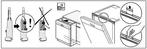
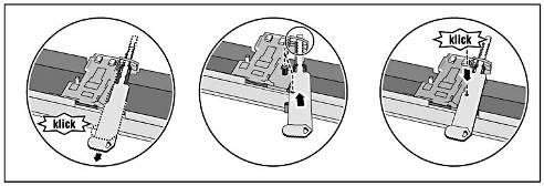
93 5.10 Power cord 2 strong catch mechanisms on the sides prevent the plug from becoming loose or coming out of the appliance Removal Disconnect the power cord from the appliance by carefully moving it up and down (not sideways!!) and simultaneously pulling the appliance plug Installation

94 5.11 Replacing feed pipe Installation Installation is in reverse sequence Removal 2. Tug the lower spray arm slightly and pull off the feed pipe. 3. Unscrew both Torx screws on the pump sump. 4. Loosen catch mechanisms in the area of the coupling point. 5. Carefully loosen top catch mechanisms on the roof sprinkler (optionally) using a small flat-blade screwdriver.

95 5.12 Removing the worktop Removal 1. Remove two screws at rear. 2. Press up both locking levers under the worktop. 3. Lift the front of the worktop slightly. 4. Push back the worktop and lift off.
96 Installation 1. Lock back of worktop into the guides with the retaining lugs. 2. Push forwards. 3. Press down front of worktop until both locking levers click into position. 4. Screw the two screws back in again.


97 5.13 Installing optional elements in the baskets Optional elements can be fitted in the baskets Tablet chute 86 cm model


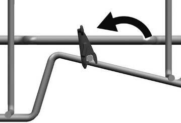
98 Cup support clip Opening the clips: When washing cups, the cup support clip can be folded up. The additional inclined position reduces the accumulation of water on the underside of the cup. In the case of tall glasses it is recommended to fold down the cup support clip. If top baskets feature optional plastic inserts, these must be removed first. Engage cup support clips.

99 Gastronorm insert holder Positioning the utensils:


100 Setting up vario cutlery drawer plus optional from 10/2011 on Press the lateral plastic inserts outward. Pull it upward from the framework. Only the disassembly of flexible elements of the vario cutlery drawer plus is shown. The assembly takes place in reverse order. Plastic parts are to be engaged evenly and examined for tightness. Remove handle: Bend latches inward. Remove handle upward.


101 Bend guide straps carefully outward. Pull flip tines from the laughter. Press the metal frames from the mounting plates in front. Push to the rear from the guidance.
102 5.14 Installing childproof lock Requirement: Worktop removed

103 5.15 Replacing / resetting door lock Installation Requirement: Worktop removed or appliance pulled out as far as rinsing tank frame Removal 1. Insert the new door lock. 2. Bend in the two metal brackets again to secure the door lock Reset 1. Straighten metal brackets on right and left of the door lock. 2. Lift off door lock. If the snap lock is locked manually (if required when using the transparent diagnosis door), the system must be released again. To do this, close the door firmly. A strong mechanical resistance must be overcome!
. 5.16.1 Removal 1.")

104 5.16 Replacing side panels Requirement: Remove worktop (if fitted) Removal 1. Loosen screws of the side panel on the front side. 2. Fold out the upper side of the side plate. 3. Push down the side panels and detach from the retaining lugs of the base pan.


105 Installation Installation 1. Attach the side panel to the catches of the appliance underside. 2. Press evenly onto the appliance. 3. Screw together side wall.


106 5.17 Removing outer door Panel screws It is not necessary to remove the topmost 6 screws in order to remove the outer door. Take hold of the sides of the outer door to prevent it falling down Removal Remove outer door by removing the 3 screws on each side of the inner door.
107 Installation Position insulating mats and force sensors. Close inner door but do not engage. 1. Push outer door with the upperside at an angle under the fascia. 2. Press outer door onto the inner door. With the door open slightly, screw together from inside. Panel screws Use 4x11 mm screws.
108 5.18 Variable hinge installation, optional Note Installation height Before pulling the dish washer out of installation mark the installation hight. (e.g.: distance (a) between floor to lower edge of the dish washer). The equipment must be aligned in the same height before assembly the furniture front Removal Requirement: base panel removed Example: 1. Pull appliance out of the installation cavity.


109 1. Remove 4 screws. 1. Remove both chrome strips.
. 1.")

110 1. Loosen lock screws (3 ~ 5 rounds). 1. Raise furniture door and 2. push it upwards till the upper slide is out of the guide.

111 1. Remove 6 housing screws from the front door. 1. Remove screws.

112 1. Pull outer door slightly away from the appliance. 2. Carefully remove downwards. 1. Move hinge upside 2. Remove both slideelements from the conduct 1
 Make sure that the upper and lower sliding elements")
113 Installing outer door 1. Insert both slideelements to the conduct 2. Move hinge upside 1. Insert outer door from below into the inner door. 2. Press outer door towards the appliance. Position of the screws When reusing the sliding elements observe the correct screw position the structure (see chapter: Mounting furniture journal) Make sure that the upper and lower sliding elements slide in the metal outer door correctly

114 1. Mount the joint on the hinge side plate and screw in from below. Installation Make sure that the joint is properly inserted into the nose with the hinge. Screws Use 4x11mm screws. 1. Assemble outer door with 6 housing screws. 2. Screw from below


115 Installing furniture door Dimensions for 86 cm models: When installing the door for the first time, attach the 4 retaining elements to the furniture door as described in the installation instructions. Dimensions for 81 cm models: 1. Mark installation points exactly with 2 mm drill bit attach 4 retaining elements exactly.

 from the upper edge of the neighbouring front to the clamping screw of the glider must correspond to the distance (c) from the upper edge of")
116 CAUTION Incorrect marking and attachment! Destruction of the furniture door The attachment points of the retaining element must be observed exactly. If the 4 retaining elements are attached unevenly or slanted, the furniture door may jam when it is being opened or closed. The screw fittings of the hand grip must always be countersunk. To ensure the the correct assembly height, the measures (b) and (c) must agree. Condition: Equipment correctly aligned The distance (b) from the upper edge of the neighbouring front to the clamping screw of the glider must correspond to the distance (c) from the upper edge of the furniture sheet up to the middle of the connection clip. Countersink screw fittings of the hand grips. Tolerance Disagree the dimensions, the height of the connection clip must be adapted!


117 Up to and including FD 9205 (Primary system) Check the locking screws. The guide part cannot be positioned securely unless the gap between the sliding elements is free. The screws must be unscrewed far enough. CAUTION Incorrect position of the locking screws! Destruction of the retaining elements or the sliding elements on the articulated joints. The locking screws must be unscrewed a long way before the furniture door can be attached. The receiving gap in the sliding elements must be free to prevent the retention lugs from catching or being blocked. 1 Guide part 2 Slider The guide part has to be positioned in such a way in the sliding elements, that the locking screw is in the centric recess.


118 From FD 9205 on (Modified system) For all FD: 1. Insert sliding elements correctly into the guides. 2. Press furniture door onto the outer door. Carefully lower furniture door as far as the stop. The screw must be screwed in, but not fixed.

119 VORSICHT Mounting by using screws The long screws, which are used in solid furnitures, are not required anymore! The mobile system can be damaged by fixing the furniture sheet. 1. Align furniture door. 2. Tighten 2 locking screws by hand. 1. Position decorative strips. 2. Screw on decorative strips.

120 1. Install appliance and 2. install base panel.
121 5.19 Replacing the dispenser Requirement: Outer door or décor panel removed Removing the dispenser CAUTION Sharp-edged sheet-metal parts! Risk of injury Wear protective gloves. 1. Take cable duct out of the catches. 2. Loosen plug-and-socket connection Removal 1. Carefully bend sheet-metal brackets away from the dispenser and press dispenser carefully inwards and ensure that it does not fall into the appliance.
122 Installation Before installing the dispenser, bend back sheet-metal brackets to the initial position. 1. Install cable guide. 2. Re-attach plug-and-socket connection. 1. Engage dispenser evenly in the door and ensure that all 8 catch mechanisms have engaged.

123 5.20 Installing the detergent cover 1. Attach long end of spring to the dispenser. 2. Attach short end of spring to the detergent cover. 3. Press cover into the dispenser.
124 Replacing EmotionLight (optionally) Requirement: Worktop (optional) removed Side panel on right removed Removal 1. Loosen plug-and-socket connection. (Carefully expose ribbon cable.) Installation 1. Remove both LEDs 2. with holder from the rinsing tank. 1. Re-attach plug-and-socket connection. (Carefully lay ribbon cable behind the hinge plate.)
125 1. Insert LEDs into the frame of the rinsing tank.


126 5.21 Replacing infolight Infolight If the Infolight must be exchanged, be examined damming mat and cable run and adapted if necessary In case of a defect the Infolight is to be renewed completely. With the installation the cutout of the damming mat and the cable run are to be examined. If the damming mat still is in the form such as illustration 1, this 15mm is to be cut out further, sees illustration 2. This is valid only for fully integrated devices without Piezooperation. Illustration 1: Cut out damming mat to FD 8810 and devices with Piezooperation Squeeze noses carefully together. Remove Infolight to the door center. Illustration 2: Cut out damming mat from FD 8811on
127 5.22 Replacing TimeLight In case of a defect the Infolight is to be renewed completely. To disassembly bend the latches (1) easily outward. Pull the TimeLight module upward from the guidance (2). Bend the latches (1) back before installation. Push the TimeLight module back into the guidance (2).


128 5.23 Replacing the fascia Outer door (if fitted) removed. Note When loosening the last screw, hold the fascia with one hand. It is no longer secure and may fall down. Use 4x16 mm screws Preparation: 1. Remove wires on left and right from the bushings. 2. Remove wire from rinse-aid sensor. 3. Remove earth wire if fitted.
129 Removal Open door. Loosen upper 6 screws. Remove fascia Installation 1. Fix fascia to the inner door and then screw in the 6 screws. 2. Re-attach plug-and-socket connections.


130 5.24 Replacing the door springs Corresponding side panel removed. Different spring systems Two different spring systems are used. Both of them are described in this chapter Removal (Spring system I) 1. Open door slightly. 2. Grip tension cord with flat-nosed pliers. 3. Close door. 1. Remove cord guide cover outwards.
131 Table of springs (spring system I): Version: Height: Colour: Mat.-Nr: Weihgts of furniture door: Max. Fully integrated 86,5 cm (39dB) Light Blue ,0 Kg to 10 Kg Remove cord system with spring (1), cord (2), deflection lever (3) and holder (4) forwards.. Min. Fully integrated 86,5 cm Pink ,0 Kg to 10 Kg Integrated 86,5 cm Green ,5 Kg to 8,5 Kg Fully integrated 81,5 cm Black ,5 Kg to 8,5 Kg Integrated 81,5 cm Blue ,5 Kg to 8,5 Kg Free standing; Build under Free standing; Build under 86,5cm+ 81,5 cm stainless steel Red ,5 cm Yellow The door springs can be identified by a coloured dot on the rear of the appliance. The door springs must be replaced in pairs only! Do not install different springs! The same colour coding must be used on the right and left!


132 Assembling Tension cord holder The tension cord holder must be attached as illustrated in order to prevent friction on the base pan. Insert tension cord to the spring (1) and fix it in the notch of the base pan (2). 1. Fix tension cord holder in the notch of the base pan. The cord system is automatically attached to the door lever.

133 Removal (Spring sytem II) See Removal Spring System I Table of springs (Spring system II) Table of springs Do not use springs of 45 cm models. The door springs can be identified by a coloured dot on the rear of the appliance. The door springs must be replaced in pairs only! Do not install different springs! The same colour coding must be used on the right and left! Max. Min. Version: Height: Colour: Mat.-Nr: Weihgts of furniture door: Fully Integrated Fully Integrated 86,5 cm (39dB) Light blue ,0 Kg to 10 Kg 86,5 cm Pink ,0 Kg to 10 Kg Integrated 86,5 cm Green ,5 Kg to 8,5 Kg Fully Integrated 81,5cm Black ,5 Kg to 8,5 Kg Integrated 81,5 cm Blue ,5 Kg to 8,5 Kg Free standing; Build under Free standing; Build under 86,5 cm + 81,5 cm Stainless steel Red ,5 cm Yellow Installing door spring 1 Spring 2 Notch Install cord system in reverse order. Fix the spring in the providet holder of the base pan. If spring is broken (1) or tension cord is torn and if it is suspected in general that the plastic holder (2) sprayed on the container is damaged: Attach new spring with the metal retaining plate enclosed with the spare part!

134 1 Metal retaining plate 2 Spring Attach metal retaining plate to spring. Noises When converting or replacing the spring, ensure in particular that the front plastic holder is correctly repositioned; otherwise it may cause noises on the side panel. 1 Metal retaining plate Hammer metal retaining plate into designated groove in base group. Place plastic holder correctly in the base group.
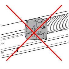
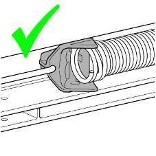
135
136 5.25 Replacing heat exchanger Requirement: Left side panel removed Heat exchanger emptied 1. Tag expansion opening nut in mounting position. 2. Remove expansion opening nut. 3. Remove cover cap (optional). 4. Remove waterinlet connection Removal of heat exchanger 1 Expansions opening-nut 3 Waterinlet connection 2 Cover, water inlet

137 1. Remove both Torx screws on the outside of the tank. 2. Bend out the guard cover of the impeller wheel counter and remove plug connection. 3. Loosen hose clamp on the water supply and remove supply hose. 4. Loosen catch mechanisms on the front of the housing. 5. Carefully pull heat exchanger forwards. In doing so, detach from the holder on the rear of the appliance and remove. After prolonged operation the heat exchanger may become stuck to the bitumen insulation and be difficult to remove. 1 Container fitting 4 Catch mechanism 2 Impeller wheel counter with cover 5 Holder 3 Water supply hose with clamp

138 Mounting heat exchanger Assembly sequence The assembly sequence described here is to be kept. Leakage Pay attention to the correct position of the sealing in the expansion opening. Prevent leakage Avoid squeezings of the connections to the Water softener and water drain hoses 1. Insert the heat exchanger to the connections of water softener and drain hoses. 2. Slip water inlet hose to heat exchanger and fix it with the clamp. 3. Press the heat exchanger to the container. 4. Lock the heat exchanger on the container. 1. Tighten the expansion opening nut to the marking. 2. To prevent leakage, around the value + 3 hours (1/4 revolution) continue to tighten. 3. Mount and tighten waterinlet connection. 4. Push cover cap (optionally) to water inlet connection. 5. Fix the heat exchanger with screws from outside to the container. 6. Connect the wheel counter with the electrical plug.
139 5.26 Replacing flow sensor Requirement: Side panel on left removed Risk of breakage Do not bend or kink boards with a flow sensor in the flask! Component is very sensitive! Carefully bend out the plastic flap on the heat exchanger / water inlet. Loosen plug-and-socket connection 1. Take complete board with flow sensor out of the catch mechanisms. 2. Unpack new flow sensor, take board out of transportation safety device and dispose of holder. 3. Carefully attach new board to the heat exchanger / water inlet. Reconnect power supply and bend back plastic flap.


140 5.27 Replacing the regeneration valve Remove anchor Requirement: Side panel on left removed. Optionally: Heat exchanger emptied. Water drained from the salt dispenser Removal 1. Insert a small screwdriver in the valve position 2. Lever the valve insert carefully loosely 3. Remove the valve insert from the regeneration unit Install in reverse sequence. 1. Rotate valve anti-clockwise. 2. Pull out valve forwards.

141 Positioning the armature 1. Align the marked points. 2. Press valve with spring back into the coil until the valve engages.

142 5.28 Replacing the drainage hose Requirement: Left side panel removed Removal 1. Loosen the panel catch mechanism. 2. Fold out the panel. 1. Press drainage hose backwards out of the holder. 2. Remove downwards from the heat exchanger / water inlet Installation Is in reverse sequence.
143 5.29 Replacing the supply hose Requirement: Left side panel removed Removal 1. Loosen the panel catch mechanism. 2. Flap to the right hand side. 3. Fold out the panel. 1. Remove electrical connection.

144 1. Open clamp. 2. Remove supply hose from the heat exchanger / water inlet Installation Is in reverse sequence.


145 5.30 Replacing the power module Requirement: Right side panel removed. Optional liquor reservoir removed. Power cord removed from the appliance Removal 1. Loosen catches and 2. lift off module. 1. Using a screwdriver, carefully lever the cap to the left and loosen the catch. 2. Lift off cap upper section.


146 Remove cap Open the power module 1. Loosen the catching by an easy hitch. 2. Remove the cap. 1. Loosen housing catches all around. 2. Pull housing parts apart.


147 Loosen cable harness Coding frames The coding frames are to be opened only if necessary. They are a component of the wiring harness and remain not on the module. 1. Loosen catch and 2. Lift off complete coding frame with plugs. Components which come into contact with electrostatic voltage will be damaged beyond repair Before carrying out any work, apply protective system to components susceptible to electrical discharge. Observe measures to protect the components suscep-tible to electrical discharge.


148 Installation Installation is in reverse sequence. The power module must engage audibly into the base pan. Re-attach the splash guard cover. 1. Insert coding frame into the guide. 2. Press down until the catch clicks into position. Plugs Respect for tighten the plug within the coding frame. Laying of cables Cables must always be installed under the cap section with water outlet channel..

149 5.31 Replacing base panel and plate Removal Incorrect removal If the base panel is slackened at the side and removed, the two holders may break off. If only one holder is damaged, the side can be changed, as both holders are the same. It is recommended to place your feet under the front of the appliance to relieve the load on the base panel.

 and remove the catch")
150 1. Loosen base plate by unscrewing the Torx screws. 2. Lever the plate out of the catches and remove. The underside of the base panel is secured with 2 catches. 1. Insert a screwdriver into the guides (1) and remove the catch mechanism downwards. 2. Remove panel upwards.


151 Installation 1. Place base plate in the catches. 2. Press up and screw together. 1. Put base panel on top. 2. Press down until it clicks into position.

152 5.32 Replacing non-return valve Removal Requirement: Outer door removed Base panel and plate removed Water removed from pump sump Drainage hose removed from pump sump Scratches During removal, do not scratch the inside of the outlet connection with a sharp-edged screwdriver. Leaks may occur.
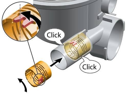
153 Installation


154 5.33 Replacing the Aquasensor Requirement: Base panel and base plate removed Installation Insert and lock board. 1. Press Aquasensor with board edgewise into the pump sump. 2. Rotate 90 to the right and lock in position Removal 1. Loosen catch mechanism. 2. Rotate Aquasensor housing by 90 to the left. 3. Pull out forwards. Seal To facilitate rotating the Aquasensor, the seal can be lubricated with Promol or rinse aid.

155 5.34 Folding down rinsing tank Removing overflow channel The rinsing tank must be folded down all the way from the base pan for the following work: Replacement of the water softening system. Replacement of the pump sump. Replacement of the heating pump. Replacement of the water points Requirements Remove overflow channel Remove drainage hose Remove float switch safety system Open supply hose grommet Remove power module Remove filling hose of water storage tank (optionally) Disconnect actuator of water storage tank (optionally) Disconnect emotion light (optionally) 1. Detach from the upper catch mechanism. 2. Take out of the lower guide.

156 Removing drainage hose Removing float switch safety system Residual water When the drainage hose is removed, residual water may run out. Catch water or remove from the base pan with suction syringe. 1. Loosen catches. 2. Remove switch upwards. 1. Press flexible drainage hose upwards out of the fixing. 2. Remove from pump sump.


157 Opening supply hose grommet (aquasop models) Opening supply hose grommet (water inlet valve models) 1. Loosen the panel catch mechanism. 2. Fold out the panel. 3. Press the hose bushing at a slight angle into the base pan to have more clearance to fold down and remove the rinsing tank. 1. Loosen locking lever. 2. Fold the cover with the inlet hose outward. 3. Remove supply hose.

158 Loosening the tank catch mechanism The rinsing tank is held and locked at the front and rear in guides on the base. The rinsing tank is fixed at the rear on the left and right with sheetmetal brackets. These are bent by a plastic lug on the base pan. 1. Using a screwdriver, detach hinge plates at the front side from the top of the catch mechanism. To do this, bend in the hinge plate catch mechanism. 1. Using a screwdriver, straighten sheet-metal brackets.
159 Folding down the rinsing tank Close salt dispenser Always check that the salt dispenser cover is screwed shut to prevent salt solution from running out subsequently when the tank is folded down! Protect support surface for the rinsing tank from being scratched. Tank is seated firmly in the guides and requires only a little force to lift it out. To facilitate handling, the appliance can be placed on its back and the base pan carefully removed. In the case of free-standing appliances, ensure that the weight does not fall out of the base pan. 1. Carefully lift rinsing tank upwards. 2. Place rinsing tank towards the rear.
 4.")
160 If the appliance is on its back and the base pan is removed, ensure that the weight does not fall out of free-standing appliances Components on the tank In this state the following components/modules which are attached to the tank can be replaced: 1. Cable harness 2. Heating pump 3. Power module (not fixed to the tank) 4. Water points with motor and pulse transmitter - optionally 5. Water softening system 6. Pump sump
161 5.35 Replacing pump sump Requirement: Rinsing tank folded down Heating pump removed Water points removed Drain pump removed Supply pipe removed Removal Risk of injury! Sharp-edged sheet-metal parts The edge of the sheet metal at the opening for the pump sump may be sharp-edged! Wear gloves. Loosen 4 screws (1. to 4.) in the interior container and remove pump sump downwards.
162 Installation Sequence of screw connections Always observe the sequence of the screw connections. Leaks may occur. Ensure that the seal is correctly positioned! Brush with a little Promol or rinse aid. Place pump sump from below directly and without tilting it on the container. Insert and tighten screws in reverse sequence: 1. at rear right 2. at rear left 3. at front left 4. at front right


163 5.36 Replacing heating pump Removing heating pump Requirement: Rinsing tank folded down Do not open heating pump. The heating pump can be replaced as a whole component only. Individual parts are not available. 1. Using side cutters, loosen the hose clamp on the water points connection. 1. Detach rubber holder from between pump unit and pump sump.

164 Installing the heating pump 1. Carefully remove/rotate heating pump off the water points hose. 2. By gently rotating the heating pump, pull it backwards. Moisten inside of rubber seal with rinse aid. 1. Push heating pump onto the pump sump and 2. press outlet channel into the water points.

165 Drain pump seal The replaced seal for the intake channel must be inserted all the way into the housing of the heating pump Cleaning the heating pump The heating pump must be cleaned from the outside only. If the heating pump is opened, the leak tightness can no longer be guaranteed when the heating pump is closed again. Tighten the hose clamp as illustrated. Hose clamp mat. no.: is required for the re-installation. The hose clamp is supplied with the spare parts water points, pump sump and heating pump (set).
 2. Loosen catch mechanism. 3. Rotate water points counter clockwise.")
166 5.37 Replacing water points Requirement: Rinsing tank folded down Circulation pump removed Removal Loosen the water points The water points housing requires effort to turn! Wear gloves. 1. Remove the hose for water storage tank (optionally) 2. Loosen catch mechanism. 3. Rotate water points counter clockwise.

167 Installation Brush rubber seal with a little Promol or rinse aid. 1. Position Z shaped piece of the water points between the two bars of the pump sump. 2. Press water points flat on the pump sump. 3. Lock in position by rotating in a clockwise direction. 4. Fix the hose from water storage tank again (optionally)

168 5.38 Replacing water softening system Requirement: Removal Rinsing tank folded down. CAUTION Risk of injury! Sharp-edged sheet parts The edge of the sheet at the opening for the water softening system may be sharp! AU-models Conditional from manufacturing, Australia models have partially a "dummy" water softener without softening pellets. The valve is replaced by a blind plug. It is important to ensure that the lid is always screwed to the water softener. 1. Loosen plug-and-socket connection on the regeneration valve.

169 Installation 1. Salt dispenser cover removed. 2. Loosen salt dispenser nut with special tool mat. no.: Remove water softening system downwards. Push water softening system from below into the rinsing tank. 1. Tighten salt dispenser nut with special tool mat. no.: Screw on cover.
 for the drain pump forwards. 3. Rotate drain pump clockwise. 4. Remove pump forwards out of the pump sump. 5.39.")
170 5.39 Replacing the drain pump Requirement: Base panel and plate removed. Water drained Removal 1. Remove plug. 2. Pull catch mechanism lever (1) for the drain pump forwards. 3. Rotate drain pump clockwise. 4. Remove pump forwards out of the pump sump Installation Proceed in reverse sequence.

171 5.40 Counterweight Rinsing tank folded down Installation Removal 1. Remove the weight upwards. 1. Check rubber damper is in correct position. 2. Insert weight into the recesses.

172 5.41 Attaching the rinsing tank Attaching the rinsing tank Ensure it is seated correctly Ensure that the weight is installed correctly in freestanding appliances. If the heat exchanger is mounted on the rinsing tank, ensure that the hose connections are clean. Do not trap supply and drainage hoses. Push water softening system into the guides. Protect power module from jamming. Protect cable harness from crushing. 1. Carefully fold the rinsing tank forwards. 2. Insert into the guides.

173 Protecting tank catch mechanisms 1. Ensure that the connection is faultless without crushing the terminals on the heat exchanger. 1. Using a screwdriver, bend hinge plate catch mechanism outwards.
174 Installing the supply hose 1. Using a screwdriver, bend over sheet-metal brackets. Take the hose bushing out of the base pan. 1. Insert panel. 2. Lock panel.


175 Installing float switch safety system Installing the drainage hose 1. Press float switch into the catch mechanism of the base plate. 1. Push drainage hose into the pump sump. 2. Press flexible drainage hose into the fixing. Insert power module and fix it.. Visual inspection Finally a visual check is on possibly gotten jammed or wrongly engaged construction units to accomplish cables or hoses Connect emotionlight and check.


176 5.42 Transparent door Permanent magnet If using the transparent door, a permanent magnet must be positioned in the inside door. It is used to signal door closed to the door contact switch. The door contact switch responds to the direction of the magnetic field. If required, turn the permanent magnet until the appliance detects the magnetic field correctly. If the snap lock is locked manually, the system must be released again. To do this, close the door firmly 1. Open appliance door. 2. Place transparent door in the appliance and engage at the top in the door lock. Order numbers: Transparent door 81 cm: Transparent door 86 cm: Magnet: Attach suction button with magnet to the upper edge of the inner door.

177 5.43 Loading appliance software UDA connection to the operating module in the door Requirement: UDA with cable and adapters Computer I-Service software DANGER Exposed live parts Danger to life caused by electric shock! Disconnect the appliance from the power supply. Do not touch housing, frame or components. Use residual-current-operated circuit-breaker if tests have to be conducted with the power on. Ensure that the resistance of the protective conductor does not exceed the standardised values. CAUTION Voltage peaks when disconnecting/connecting the plugin contacts The operating module or the Piezo power supply unit (optional) will be destroyed by the mains potential on the earth cable of the bus system. Disconnect the appliance from the power supply before disconnecting/connecting plug-in connections. Do not connect Y cable to the power module. Disconnect the appliance from the power supply. 1. Connect Y-cable to the operating module. 2. Connect to UDA. Reconnect appliance to the power supply.


178 UDA connection to the power module Software The UDA connection cable can also be connected directly to the power module. The Y-cable must not be used for this connection. Open iservice Software on the computer and load appliance software. When flashing is complete, switch off the appliance and disconnect from the power supply (reset mains) After the main reset, a software / programm reset must be done in any case. Insert UDA connection cable into the free i-service/d-bus² connection. If both slots are occupied, unplug the lower plug and use this slot. The function of the operating module is then retained.
179 5.44 Technical specifications Power consumption in stand by: Operating panel with push buttons: Operating panel with Piezoelectronic: Time delay mode, cycle end mode & left open mode < 0,1 W < 0,8 W Max. 2,5 W Main power voltage range: EU, CH, V 50/60 Hz GB, BS, TH, AU UC 120V 60 Hz BR, MX 127V 60 Hz JP 200V 50/60Hz TC 110V 60 Hz
180 ADDENDUM Service Program (3 pages) This section provides instructions on how to enter and exit the Service Program, run Service Diagnostics, and access Error Codes for the Jenn-Air Flush Mount Dishwasher. Service Diagnostics (3 pages) This section provides information on the Service Diagnostic program for the Jenn-Air Flush Mount Dishwasher. Diagnostic tests includes component activation, checks and measurements, anticipated values, and approximate time per tests. NOTE: Some tests cannot be skipped. Error Codes (5 pages) This section provides a list of the Error Codes for the Jenn-Air Flush Mount Dishwasher. Additional information includes a description of the codes, appliance behavior, and possible causes. ADDENDUM


181 Service Program ADDENDUM - SERVICE PROGRAM Page 1 of 3
1 INTRODUCTION Low salt detection SAFETY CONSTRUCTION AND FUNCTION DIAGNOSTICS...54
 REPAIR INSTTRUCTTI I ION 1 INTRODUCTION... 3 3.15 Low salt detection... 26 1.1 Purpose of the document... 3 1.2 General symbols... 3 1.3 Safety-relevant symbols... 3 2 SAFETY... 4 2.1 Qualifications of
1 INTRODUCTION SAFETY CONSTRUCTION AND FUNCTION... 9
 1 INTRODUCTION... 4 1.1 Purpose of the document... 4 1.2 General symbols... 4 1.3 Safety-relevant symbols... 5 2 SAFETY... 6 2.1 Qualifications of service technicians... 6 2.2 Identification of danger
1 SAFETY Aqua Stop valve INSTALLATION OPERATION FUNCTIONS REPAIR COMPONENTS
 REPAIR INSTTRUCTTI I ION Dishwasher 1 SAFETY... 3 4.3 Aqua Stop valve... 21 2 INSTALLATION... 4 2.1 Aligning the appliance... 4 2.2 Electrical connection... 4 2.3 Water connection... 4 3 OPERATION... 5
1 SAFETY NTC R3 end shield REPAIR INSTALLATION Installing the motor / belt OPERATION FUNCTIONS...
 REPAIR INSTTRUCTTI I ION 1 SAFETY... 3 5.6 NTC R3 end shield... 16 1.1 Safety instructions... 3 1.2 Qualifications of service technicians... 4 1.3 Identification of danger levels... 4 5.7 Safety thermoregulator
Service Manual - Series 450/451 IG IGV IG IGV IG IG IG IGV IG
 Service Manual - Series 450/451 IG 448... IGV 449... IG 458... IGV 459... IG 459... IG 4408.0 IG 4406.0 IGV 4408.0 IG 4408.1 Service Manual: H7-71-04 Responsible: Dieter Rutz KÜPPERSBUSCH HAUSGERÄTE AG
1 SAFETY Rinsing and pumping system INSTALLATION OPERATION FUNCTIONS REPAIR FAULT DIAGNOSTICS...
 REPAIR INSTTRUCTTI I ION Dishwasher 1 SAFETY...2 4.13 Rinsing and pumping system... 20 2 INSTALLATION...3 2.1 Aligning the appliance...3 2.2 Electrical connection...3 2.3 Water connection...3 3 OPERATION...4
Technical Description: / Rev, Seq: H, 1 / Date: Remarks. At Customer error case. Blinking LED's at end of Flash process
 Technical Description: 56000000157007 / Rev, Seq: H, 1 / Date: 29.06.2010 Material No. 9000 361 479 Function Actuation Display Remarks Error class (failure group) In Customer Service program At Customer
Technical Description: / Rev, Seq: F, 2 / Date: Remarks. At Customer error case. Blinking LED's at end of Flash process
 Technical Description: 56000000157007 / Rev, Seq: F, 2 / Date: 17.09.2009 Function Actuation Display Remarks Material No. 9000 361 479 Error class (failure group) In Customer Service program At Customer
B/S/H/ Fault Codes and Service Programmes PG
 LED LED LED off E:00 No error - - - - - - h:00 h:24 No error Appliance does not start Delay timer is activated! No appliance fault! All LED s are on LED s flashing Interface error Appliance without function
User manual. Dishwasher ZDTS102. Downloaded from manuals search engine
 User manual Dishwasher ZDTS102 Contents Safety information _ 2 Control panel 3 Washing programmes _ 4 Use of the appliance 5 Set the water softener _ 6 Use of dishwasher salt _ 7 Use of rinse aid 7 Load
MW402 Integrated Dishwasher
 MW402 Integrated Dishwasher Manual for Installation, Use and Maintenance 1 Customer Care Department The Group Ltd. Harby Road Langar Nottinghamshire NG13 9HY T : 01949 862 012 F : 01949 862 003 E : customer.care@cda.eu
Glass and Dishwashers 402/452/502. (original instructions) (incl. Australian /502) Starting from Serial No.:
 (incl. Australian /502) Starting from Serial No.:") Glass and Dishwashers ECOMAX 402/452/502 (incl. Australian 452-90/502) INSTALLATION AND OPERATION INSTRUCTIONS (original instructions) Starting from Serial No.: 8663 4000 REV. 05.10.2015 EN IMPORTANT NOTES
Glass and Dishwashers ECOMAX 402/452/502 (incl. Australian 452-90/502) INSTALLATION AND OPERATION INSTRUCTIONS (original instructions) Starting from Serial No.: 8663 4000 REV. 05.10.2015 EN IMPORTANT NOTES
Operating instructions
 Operating instructions for Winterhalter Gastronom dishwasher GS 502 and GS 515 Contents Page 1 Intended use... 1 2 Installation and commissioning... 1 3 Safety instructions... 2 4 Operating panel... 3
Glass and Dishwashers AMX / AUX Series
 Glass and Dishwashers AMX / AUX Series INSTALLATION OPERATION VERSION 24.02.04 Important Notes Use in Accordance with Regulations This machine is exclusively to be used to wash ware such as plates, cups,
MW401 Integrated Dishwasher
 MW401 Integrated Dishwasher Manual for Installation, Use and Maintenance Customer Care Department The Group Ltd. Harby Road Langar Nottinghamshire NG13 9HY T : 01949 862 012 F : 01949 862 003 E : service@cda.eu
Engineers manual. Under counter machines
 Table of Contents 1. INTRODUCTION... 3 1.1 1.2 1.3 INSTALLATION AND COMMISSIONING... 3 SERVICE AND REPAIRS... 3 MODIFICATION... 3 2. EXPLANATION OF SYMBOLS USED... 3 3. WARNING AND SAFETY INFORMATION...
User Manual. Dishwasher ZDM17301SA ZDM17301WA
 EN User Manual Dishwasher ZDM17301SA ZDM17301WA Contents Safety information 2 Safety instructions 3 Product description 4 Control panel 5 Programmes 6 Daily Use 7 Hints and tips 10 Care and cleaning 11
TECHNICAL INFORMATION G1000 / G2000 Dishwashers
 TECHNICAL INFORMATION G1000 / G2000 Dishwashers 1 G1000 / G2000 Dishwasher - Table of Contents WARNINGS AND SAFETY INFORMATION...10 1.0 CONSTRUCTION AND DESIGN...11 1.1 Appliance Overview...11 1.1.1 Appliance
BarAid 400. Installation and. Starting from Serial No.:
 Glasswasher BarAid 400 Installation and operation Instructions Starting from Serial No.: 8649 1065 REV. 19.01.2009 DE 1618-A-01-09 Content Page 1 Important Notes... 4 2 Installation... 5 2.1 Location...
TECHNICAL INFORMATION Touchtronic Clothes Dryers
 TECHNICAL INFORMATION Touchtronic Clothes Dryers Includes: T1302, T1303, T1322, T1329ci T1403 & T1405 2004 Miele This page intentionally left blank. Table of Contents GENERAL INFORMATION A. Warning and
WC600 Integrated Dishwasher Installation, Use and Maintenance
 WC600 Integrated Dishwasher Installation, Use and Maintenance Customer Care Department The Group Ltd. Harby Road Langar Nottinghamshire NG13 9HY T : 01949 862 012 F : 01949 862 003 E : customer.care@cda.eu
HX-30/40 and HX-30/40 S Glass and Dishwashers
 HX-30/40 and HX-30/40 S Glass and Dishwashers INSTALLATION OPERATION VERSION 18/01/00 2 Installation and Operation Instructions for Model HX-30/40 and HX-30/40 S (with built-in softener) Content Page 1
Glass and Dishwashers AMX / AUX Series
 Glass and Dishwashers AMX / AUX Series INSTALLATION OPERATION REV. 8.xx 04.07.2005 Installation and Operation Instructions for Models of AMX / AUX Series Content Page 1 Installation... 3 2 Connections...
B/S/H/ Fault Codes and Service Programmes PG
 off on E:00 No error - - - - - - h:00 h:24 No error Appliance does not start Delay timer is activated! No appliance! All s are on s flashing Interface error Appliance without function Appliance without
ATAG VA3.. VA9011ZT / XT VA(9)6211Q /R/S/T
6211Q /R/S/T") ATAG VA3.. VA9011ZT / XT VA(9)6211Q /R/S/T General information The machine may be connected to a hot water tap upto 60 C. For cleaner and dryer results however, it is advised to connect the machine to
ATAG VA3.. VA9011ZT / XT VA(9)6211Q /R/S/T General information The machine may be connected to a hot water tap upto 60 C. For cleaner and dryer results however, it is advised to connect the machine to
en Instructions for use
 en Instructions for use Index Safety instructions....... 4 Delivery.................... 4 Installation................. 4 In daily use................. 4 Children in the household.... 4 Childproof lock
Glass and Dishwashers. BarAid 500/800. Installation and. Starting from Serial No.:
 Glass and Dishwashers BarAid 500/800 Installation and operation Instructions Starting from Serial No.: 8652 0001 REV. 19.01.2009 1617-A-01-09 Content Page 1 Important Notes... 4 2 Installation... 5 2.1
1 SAFETY INSTALLATION OPERATION FAULT DIAGNOSTICS COMPONENTS FUNCTIONS TECHNICAL SPECIFICATIONS...
 1 SAFETY... 2 1.1 Safety instructions... 2 1.3 ESD... 3 2 INSTALLATION... 5 2.1 Installation / Connection... 5 2.2 Technical data... 5 3 OPERATION... 6 3.1 Control panel operation... 6 4 COMPONENTS...
MW001 Integrated Dishwasher. Manual for Installation, Use and Maintenance
 MW001 Integrated Dishwasher Manual for Installation, Use and Maintenance Important The CDA Group Ltd cannot be held responsible for injuries or losses caused by incorrect use or installation of this product.
Manual for installation, use and maintenance MW200. Integrated Slimline Dishwasher. year. parts + 1 year labour guarantee.
 Manual for installation, use and maintenance MW200 Integrated Slimline Dishwasher year parts + 1 year labour guarantee www.matrixappliances.co.uk Contents: 3 Important information 5 Important notes 6 Recommendations
user manual Dishwasher ESL 46510
 user manual Dishwasher ESL 46510 2 electrolux CONTENTS Electrolux. Thinking of you. Share more of our thinking at www.electrolux.com Safety information 2 Product description 5 Control panel 5 Use of the
Dishwasher DF 460 DF 461
 Gaggenau Operating instructions Dishwasher DF 460 DF 461 9000 407 068 (8811) en en Index Safety instructions.................... 4 Delivery............................. 4 Installation...........................
en Instructions for use
 en Instructions for use Index Safety instructions....... 4 Delivery.................... 4 Installation................. 4 In daily use................. 4 Children in the household.... 4 Childproof lock
wc431 Slimline Integrated Dishwasher Manual for Installation, Use and Maintenance
 wc431 Slimline Integrated Dishwasher Manual for Installation, Use and Maintenance Contents Contents... 2 Important... 3 Important Notes... 4 Recommendations... 5 Before First Use... 5 Control Panel...
11/2012. Mod: D281/EKA-NP. Production code:
 11/2012 Mod: D281/EKA-NP Production code: 916658 INSTRUCTION MANUAL FOR DISHWASHERS UK CONTENTS CHAP 1 PREFACE... 2 CHAP 2 INSTALLATION... 2 2.1 UNPACKING... 2 2.2 POSITIONING... 3 2.3 ELECTRICAL CONNECTION...
Repair Instructions Dishwashers
 Repair Instructions Dishwashers 1 Concerning this document 3 1.1 Important information...3 1.2 Explanation of symbols...3 2 Safety 5 2.1 Qualification... 5 2.2 General safety information... 5 2.3 Product-specific
en Instructions for use
 en Instructions for use Index Safety instructions....... 4 Delivery.................... 4 Installation................. 4 In daily use................. 4 Children in the household.... 4 Childproof lock
FAVORIT 55200VI EN DISHWASHER USER MANUAL
 FAVORIT 55200VI EN DISHWASHER USER MANUAL 2 FOR PERFECT RESULTS Thank you for choosing this AEG product. We have created it to give you impeccable performance for many years, with innovative technologies
Refrigerator KE T
 Refrigerator KE 680-1-3T Service Manual: H8-74-07 Responsible: U. Laarmann KÜPPERSBUSCH HAUSGERÄTE AG E-mail: uwe.laarmann@kueppersbusch.de Tel.: (0209) 401-732 Customer Service Fax: (0209) 401-743 Postfach
WC370 Integrated Intelligent dishwasher Manual for Installation, Use and Maintenance
 WC370 Integrated Intelligent dishwasher Manual for Installation, Use and Maintenance Customer Care Department The Group Ltd. Harby Road Langar Nottinghamshire NG13 9HY T : 01949 862 012 F : 01949 862 003
WC141 Integrated Dishwasher Installation, Use and Maintenance
 WC141 Integrated Dishwasher Installation, Use and Maintenance Customer Care Department The Group Ltd. Harby Road Langar Nottinghamshire NG13 9HY T : 01949 862 012 F : 01949 862 003 E : customer.care@cda.eu
aus Instructions for use
 aus Instructions for use Index Safety instructions....... 4 Delivery.................... 4 Installation................. 4 In daily use................. 4 Children in the household.... 4 Childproof lock
Contents. 1. Description of the controls 2 2. Operating instructions Cleaning and maintenance Troubleshooting 28
 Contents 1. Description of the controls 2 2. Operating instructions 11 3. Cleaning and maintenance 23 4. Troubleshooting 28 Thank you for choosing one of our products. You are advised to read this manual
en Instructions for use
 en Instructions for use Index Safety instructions....... 4 Delivery.................... 4 Installation................. 4 In daily use................. 4 Children in the household.... 4 Childproof lock
en Instructions for use
 en Instructions for use Index Safety instructions....... 4 Delivery.................... 4 Installation................. 4 In daily use................. 4 Children in the household.... 4 Childproof lock
All spares available from. System-Matic Ltd
 All spares available from System-Matic Ltd 0844 272 0556 Copyright Notice: All rights reserved. No parts of this manual may be reproduced in any form without express written permission of Maidaid-Halcyon
Manual for installation, use and maintenance MW402. Integrated Dishwasher. year. parts + 1 year labour guarantee.
 Manual for installation, use and maintenance MW402 Integrated Dishwasher year parts + 1 year labour guarantee www.matrixappliances.co.uk Contents: 3 Important information 5 Important notes 5 Recommendations
GETTING STARTED? EASY.
 User Manual GETTING STARTED? EASY. ZDF26001WA ZDF26001XA EN User Manual Dishwasher SAFETY INFORMATION Before the installation and use of the appliance, carefully read the supplied instructions. The manufacturer
FAVORIT34502VIO. EN User Manual
 FAVORIT34502VIO EN User Manual 2 www.aeg.com CONTENTS 1. SAFETY INFORMATION...3 2. SAFETY INSTRUCTIONS... 4 3. PRODUCT DESCRIPTION... 6 4. CONTROL PANEL...6 5. PROGRAMMES... 7 6. SETTINGS... 8 7. BEFORE
SERVICE MANUAL DISHWASHERS DIVA ACCESSIBILITY DISHWASHERS
 SERVICE MANUAL DISHWASHERS DIVA ELECTROLUX HOME PRODUCTS S.p.A. Publication no. Spares Operations Italy Corso Lino Zanussi,30 I - 33080 PORCIA /PN (ITALY) 599 38 70-09 Fax +39 0434 394096 EN DISHWASHERS
GETTING STARTED? EASY.
 User Manual GETTING STARTED? EASY. ZDF22017WA EN User Manual Dishwasher SAFETY INFORMATION Before the installation and use of the appliance, carefully read the supplied instructions. The manufacturer is
WF140 Freestanding Dishwasher
 WF140 Freestanding Dishwasher Installation, Use and Maintenance Customer Care Department The Group Ltd. Harby Road Langar Nottinghamshire NG13 9HY T : 01949 862 012 F : 01949 862 003 E : customer.care@cda.eu
GETTING STARTED? EASY.
 User Manual GETTING STARTED? EASY. ZDT21006FA EN User Manual Dishwasher SAFETY INFORMATION Before the installation and use of the appliance, carefully read the supplied instructions. The manufacturer is
TECHNICAL INFORMATION T 15xx Dryers
 TECHNICAL INFORMATION T 15xx Dryers 2010 Miele USA Table of Contents 1.0 2.0 3.0 T 15xx Dryers Construction and Design... 5 1.1 Appliance Overview Vented Models... 5 1.2 Appliance Overview Condenser Models...
GETTING STARTED? EASY.
 User Manual GETTING STARTED? EASY. ZDT24003FA EN User Manual Dishwasher SAFETY INFORMATION Before the installation and use of the appliance, carefully read the supplied instructions. The manufacturer is
User manual. Dishwasher ZDT15010FA
 EN User manual Dishwasher ZDT15010FA Contents Safety instructions 2 Control panel 3 Programmes _ 4 Options _ 5 Before first use _ 6 Daily use _ 7 Hints and tips 9 Care and cleaning _ 10 Troubleshooting
BEFORE USING THE DISHWASHER/CONNECTIONS
 INSTRUCTIONS FOR USE BEFORE USING THE DISHWASHER/CONNECTIONS ELECTRICAL CONNECTION PRECAUTIONS AND GENERAL RECOMMENDATIONS HOW TO FILL THE SALT CONTAINER HOW TO FILL THE RINSE AID DISPENSER HOW TO FILL
FAVORIT VI DISHWASHER USER MANUAL
 FAVORIT 55002 VI DISHWASHER USER MANUAL 2 CONTENTS 4 SAFETY INFORMATION 6 PRODUCT DESCRIPTION 7 CONTROL PANEL 8 PROGRAMMES 9 OPTIONS 10 BEFORE FIRST USE 13 DAILY USE 16 CARE AND CLEANING 17 TROUBLESHOOTING
FAVORIT DISHWASHER USER MANUAL
 FAVORIT 77000 DISHWASHER USER MANUAL 2 CONTENTS 4 SAFETY INFORMATION 6 PRODUCT DESCRIPTION 7 CONTROL PANEL 8 PROGRAMMES 10 OPTIONS 11 BEFORE FIRST USE 14 DAILY USE 17 CARE AND CLEANING 18 TROUBLESHOOTING
Before loading dishes into the baskets, remove coarse food remains: e.g. bones, fish bones etc. that may block the filter, or damage the wash pump.
 FOR THE FIRST TIME: 1. Set the water hardness. This will ensure optimum wash performance. Contact your local water board to find out the water hardness of the area in which you live. Adjust the dishwasher
GETTING STARTED? EASY.
 User Manual GETTING STARTED? EASY. ZDF21001WA ZDF21001XA ZDF21001NA EN User Manual Dishwasher SAFETY INFORMATION Before the installation and use of the appliance, carefully read the supplied instructions.
User manual. Dishwasher ZDI12001
 EN User manual Dishwasher ZDI12001 Contents Safety information 2 Product description _ 3 Control panel 3 Programmes 4 Before first use _ 4 Daily use 7 Care and cleaning 9 Troubleshooting 9 Technical information
User manual. Dishwasher ZDT12041FA
 EN User manual Dishwasher ZDT12041FA Contents Safety instructions 2 Control panel 3 Programmes _ 4 Options _ 4 Before first use _ 5 Daily use _ 7 Hints and tips 9 Care and cleaning 9 Troubleshooting 10
Dishwasher (8911) aus. Operating instructions
 aus. Operating instructions") Dishwasher 9000 520 318 (8911) aus Operating instructions Reset 3 sec. 10 9 8 7 6 End 9h 6h 3h Start 1 2 3 4 End 9h 6h 3h 5 20 21 22 23 24 25 26 27 28 29 30 31 aus Table of contents Safety instructions.................
Dishwasher 9000 520 318 (8911) aus Operating instructions Reset 3 sec. 10 9 8 7 6 End 9h 6h 3h Start 1 2 3 4 End 9h 6h 3h 5 20 21 22 23 24 25 26 27 28 29 30 31 aus Table of contents Safety instructions.................
SERVICE MANUAL. Ecoboiler Model range: T20 ( ) T30 ( )
 T30 ( )") SERVICE MANUAL Ecoboiler Model range: T20 (1000662) T30 (1000663) Marco Beverage Systems Ltd. 63d Heather Road, Sandyford Industrial Estate, Dublin 18, Republic of Ireland Ireland Tel: (01) 295 2674 Ireland
SERVICE MANUAL Ecoboiler Model range: T20 (1000662) T30 (1000663) Marco Beverage Systems Ltd. 63d Heather Road, Sandyford Industrial Estate, Dublin 18, Republic of Ireland Ireland Tel: (01) 295 2674 Ireland
FAVORIT 66609M0P FAVORIT 66609W0P. EN User Manual
 FAVORIT 66609M0P FAVORIT 66609W0P EN User Manual 2 www.aeg.com CONTENTS 1. SAFETY INFORMATION...3 2. SAFETY INSTRUCTIONS... 4 3. PRODUCT DESCRIPTION... 5 4. CONTROL PANEL...6 5. PROGRAMMES... 7 6. SETTINGS...
WC432 Integrated Slimline Dishwasher Installation, Use and Maintenance
 WC432 Integrated Slimline Dishwasher Installation, Use and Maintenance Customer Care Department The Group Ltd. Harby Road Langar Nottinghamshire NG13 9HY T : 01949 862 012 F : 01949 862 003 E : customer.care@cda.eu
Engineers manual. Pass Through machines P500 P500 A P500 AS P500 A WS P500 AS WS. A- AirBreak WS Water Softener. AS Dual Rinse Element
 P500 P500 A P500 AS P500 A WS P500 AS WS A- AirBreak WS Water Softener AS Dual Rinse Element Table of Contents 1. INTRODUCTION... 3 1.1 1.2 1.3 INSTALLATION AND COMMISSIONING... 3 SERVICE AND REPAIRS...
SERVICE MANUAL DISHWASHERS
 SERVICE MANUAL DISHWASHERS ELECTROLUX HOME PRODUCTS Customer Care - EMEA Training and Operations Support Technical Support Publication number Dishwashers with electronic control system DOROTEA 599 77 29
EDW500 / EDW503. Electronic Controls for Dishwashers
 EDW500 / EDW503 Electronic Controls for Dishwashers ESSE-N / A.S. October 2004 EDW500 - EDW503 EDW500 and EDW503: new entry level electronic controls for dishwashers in the DIVA family Intended to replace
1 SAFETY INSTALLATION REPAIR OPERATION COMPONENTS FAULT DIAGNOSTICS... 34
 ASCENTTA DW REPAIR INSTTRUCTTI I ION 1 SAFETY... 3 1.1 General hazards...3 1.2 Electrical shock / fire hazards...3 1.3 Plumbing / scalding hazards...3 2 INSTALLATION... 4 2.1 Pre-Install checklist...4
User manual. Dishwasher ZDT15002
 EN User manual Dishwasher ZDT15002 Contents Safety information 2 Product description _ 3 Control panel 4 Programmes 4 Options _ 5 Before first use _ 5 Daily use 7 Care and cleaning 9 Troubleshooting 10
The dishwashers washing machine tumble dryer
 The dishwashers washing machine tumble dryer Dishwashers 400 series 252 Planning notes 256 Accessories special accessories 264 Technical specifications 266 Washing machine 268 Tumble dryer 269 Technical
FAVORIT 34502VI0. EN User manual
 FAVORIT 34502VI0 EN User manual 2 www.aeg.com CONTENTS 1. SAFETY INSTRUCTIONS...................................................... 3 2. PRODUCT DESCRIPTION.....................................................
TECHNICAL INFORMATION T1500 Series Clothes Dryers
 TECHNICAL INFORMATION T1500 Series Clothes Dryers 2003 Miele - Table of Contents 1.0 CONSTRUCTION & DESIGN 1.1 Appliance Overview - Vented 1 1.2 Appliance Overview Condenser Models 2 1.3 Controls Overview
User Manual. Dishwasher IDSH604W
 EN User Manual Dishwasher IDSH604W Contents Safety information 2 Safety instructions 3 Product description 4 Control panel 5 Programmes 5 Settings 6 Before first use 8 Safety information Daily use 9 Hints
User Manual Dishwasher FAVORIT 66602VI0P
 EN User Manual Dishwasher FAVORIT 66602VI0P 2 www.aeg.com CONTENTS 1. SAFETY INFORMATION...3 2. SAFETY INSTRUCTIONS... 4 3. PRODUCT DESCRIPTION... 5 4. CONTROL PANEL...6 5. PROGRAMMES... 7 6. SETTINGS...
Drying Cabinet Installation and Operating Manual
 Drying Cabinet Installation and Operating Manual Model:- ECO Dryer 2.0 HP Heat Pump Technology CONTENTS THIS USER MANUAL 3 DATA PLATE DETAILS 3 ADVICE ON SAFE OPERATION 3 DESCRIPTION OF THE CABINET 4 AIR
2 INSTALLATION OPERATION TECHNICAL SPECIFICATIONS COMPONENTS FUNCTIONS REPAIR Series TS14/TDS14/PL138
 REPAIR INSTTRUCTTI I IONS Series TS14/TDS14/PL138 1 SAFETY... 2 7 FAULT DIAGNOSTICS...19 1.1 Safety precautions... 2 1.2 Trouble-shooting... 2 2 INSTALLATION... 3 3 OPERATION... 4 3.1 Components... 4 3.2
COMPONENTS AND FUNCTIONALITY
 COMPONENTS AND FUNCTIONALITY ESSE-N / A.S. 1 Common Circulation Pumps DIVA ZM+DGN 2 suppliers (FHP - Sole) fully interchangeable same performances versions: with / without tachymetric generator with /
GETTING STARTED? EASY.
 User Manual GETTING STARTED? EASY. ZDT24001FA EN User Manual Dishwasher SAFETY INFORMATION Before the installation and use of the appliance, carefully read the supplied instructions. The manufacturer is
Ecoboiler T20 & T30 SERVICE MANUAL. Marco Beverage Systems Ltd. 63d Heather Road, Sandyford Industrial Estate, Dublin 18, Republic of Ireland
 Ecoboiler T20 & T30 SERVICE MANUAL Marco Beverage Systems Ltd. 63d Heather Road, Sandyford Industrial Estate, Dublin 18, Republic of Ireland Ireland Tel: (01) 295 2674 Ireland Fax: (01) 295 3715 UK Tel:
ã=warning Safety instructions
 HQ 2SHUDWLQJ LQVWUXFWLRQV 'LVKZDVKHU 6 Table of contents Safety instructions................. 4 Delivery........................ 4 Installation...................... 4 In daily use.....................
1998 DISHWASHERS Servicing and Troubleshooting
 CONSUMER SERVICES TECHNICAL EDUCATION GROUP PRESENTS KD-10 1998 DISHWASHERS Servicing and Troubleshooting MODELS DU800DWG DU801DWG DU805DWG DU810DWG DP840DWG DU840DWG DU850DWG DU890DWG DU910PFG DP920PFG
ESL 5201LO EN DISHWASHER USER MANUAL
 ESL 5201LO EN DISHWASHER USER MANUAL 2 www.electrolux.com CONTENTS 1. SAFETY INFORMATION... 2 2. SAFETY INSTRUCTIONS...4 3. PRODUCT DESCRIPTION... 5 4. CONTROL PANEL...6 5. PROGRAMMES...6 6. SETTINGS...
User manual. Dishwasher ZDI12010XA
 EN User manual Dishwasher ZDI12010XA Contents Safety instructions 2 Control panel 4 Programmes _ 4 Before first use _ 5 Daily use _ 7 Hints and tips 9 Care and cleaning 9 Troubleshooting 10 Technical information
User Manual Dishwasher FAVORIT 56302MO FAVORIT 56302WO
 EN User Manual Dishwasher FAVORIT 56302MO FAVORIT 56302WO 2 www.aeg.com CONTENTS 1. SAFETY INFORMATION...3 2. SAFETY INSTRUCTIONS... 4 3. PRODUCT DESCRIPTION... 5 4. CONTROL PANEL...6 5. PROGRAMMES...
(8904) aus. Operating instructions
 aus. Operating instructions") 9000 441 492 (8904) aus Operating instructions S 1 2 3 4 5 6 7 8 9 Reinigen fertig in 1:08 Std. A B C 11 10 Reset 3 sec. 20 21 22 23 24 25 26 27 28 29 30 31 aus Table of contents Safety instructions.................
9000 441 492 (8904) aus Operating instructions S 1 2 3 4 5 6 7 8 9 Reinigen fertig in 1:08 Std. A B C 11 10 Reset 3 sec. 20 21 22 23 24 25 26 27 28 29 30 31 aus Table of contents Safety instructions.................
INSTALLATION & OPERATION Rev 1.00A DISTRIBUTED EXCLUSIVELY BY CMA DISHMACHINES KNOTT AVENUE GARDEN GROVE, CALIFORNIA 92841
 MODEL UC 60e INSTALLATION & OPERATION Rev 1.00A DISTRIBUTED EXCLUSIVELY BY CMA DISHMACHINES 12700 KNOTT AVENUE GARDEN GROVE, CALIFORNIA 92841 800-854- 6417 FAX 714-895-2141 www.cmadishmachines.com TABLE
541D19 SERIES. Technical Manual. A Division of Aquion Partners L.P.
 541D19 SERIES Technical Manual A Division of Aquion Partners L.P. Table of Contents Introduction... Page 1 Technical Specifications... Page 2 Flow Diagrams... Page 3 Injector & Flow Control Selection Injector...
aáëüï~ëüéê=ëéêáéë=bat=nrmp cìååíáçå~äáíáéë
 aáëüï~ëüéê=ëéêáéë=bat=nrmp cìååíáçå~äáíáéë Service Manual: H7-74-03D Product identification Code for the production numbers used for the various models (PNC) F.S. - Free-standing B. I. - Partially integrated
Get usage advice, brochures, trouble shooter, service information: Register your product for better service:
 FAVORIT 66603VI0P EN User Manual 2 www.aeg.com CONTENTS 1. SAFETY INFORMATION...3 2. SAFETY INSTRUCTIONS... 4 3. PRODUCT DESCRIPTION... 5 4. CONTROL PANEL...6 5. PROGRAMMES... 7 6. SETTINGS... 8 7. OPTIONS...
en Index Safety instructions... 4 Getting to know your appliance.. 6 Water softener... 7 Filling the salt dispenser... 8 Adding rinse aid...
 Index Safety instructions............. 4 Getting to know your appliance.. 6 Water softener................ 7 Filling the salt dispenser........ 8 Adding rinse aid............... 9 Utensils......................
AQUARIUS 45 MARINE SERVICE MANUAL
 AQUARIUS 45 MARINE SERVICE MANUAL CONTENTS: PAGE 1. INTRODUCTION 3 2. SAFETY INSTRUCTIONS 4 3. BASIC INSTRUCTIONS 5 3.1. Installation Details 5 3.2. Operating the Boiler for the First Time 6 3.3. Troubleshooting
DAILY REFERENCE GUIDE PRODUCT DESCRIPTION APPLIANCE CONTROL PANEL. Before using the appliance carefully read Health and Safety guide.
 DAILY REFERENCE GUIDE EN THANK YOU FOR BUYING A ARISTON PRODUCT. In order to receive a more complete assistance, please register your appliance on: www.aristonbrand.com You can download the Safety Instructions
User manual. Dishwasher DX 203
 User manual Dishwasher DX 203 Contents Safety information _ 2 Control panel 3 Washing programmes _ 4 Use of the appliance 5 Use of rinse aid 5 Loading cutlery and dishes 6 Use of detergent 7 Select and
INDEX D1976 DISHWASHER (DW955)
") 1 INDEX D1976 DISHWASHER (DW955) PROGRAMS 2 ELECTRICAL FUNCTIONS 6 PART NUMBER SUFFIX DEFINITIONS 8 SPARE PARTS LIST Casing and related parts 10 Container and related parts 12 Door 14 Control Panel 16
1 INDEX D1976 DISHWASHER (DW955) PROGRAMS 2 ELECTRICAL FUNCTIONS 6 PART NUMBER SUFFIX DEFINITIONS 8 SPARE PARTS LIST Casing and related parts 10 Container and related parts 12 Door 14 Control Panel 16
Slimline Dishwasher Instruction Manual
 Slimline Dishwasher Instruction Manual Model Number: RHSLDW1 Please read these instructions carefully and keep them for future reference For Customer Services, Spare Parts & Manufacturer s Warranty Information,
FAVORIT VI EN DISHWASHER USER MANUAL.
 FAVORIT 88060 VI EN DISHWASHER USER MANUAL 2 FOR PERFECT RESULTS Thank you for choosing this AEG product. We have created it to give you impeccable performance for many years, with innovative technologies
Installation & Operators Manual
 Installation & Operators Manual Eco, Hydro and Duo under counter range Part number 902.0001 Revison B Installation and Operation instructions For Classeq under counter range of glass and dishwashers. Section